DSA-151L/181L,DSB-181L-1 (Page 1)
60
Contents CONTENTS 1. Specifications ................................................................................................2 2. Outline and Dimensions .................................................................................3 3. Operation .....................................................................................................5 4. Wiring Diagram ..........................................................................................17 5. Refrigerant Cycle .........................................................................................22 6. Control Block Diagram.................................................................................23 7. Electric Circuit Diagram................................................................................24 8. Trouble Shooting..........................................................................................27 9. Disassembly Instructions ...............................................................................43 1) Indoor Unit ..............................................................................................43 2) Outdoor Unit ...........................................................................................45 3) Exploded Diagram (Indoor Unit) ...............................................................47 4) Exploded Diagram (Outdoor Unit) ............................................................50 5) Control Box Assembly ..............................................................................56
-
Upload
khangminh22 -
Category
Documents
-
view
0 -
download
0
Transcript of DSA-151L/181L,DSB-181L-1 (Page 1)

Contents
CONTENTS
1. Specifications ................................................................................................2
2. Outline and Dimensions .................................................................................3
3. Operation .....................................................................................................5
4. Wiring Diagram..........................................................................................17
5. Refrigerant Cycle .........................................................................................22
6. Control Block Diagram.................................................................................23
7. Electric Circuit Diagram................................................................................24
8. Trouble Shooting..........................................................................................27
9. Disassembly Instructions ...............................................................................43
1) Indoor Unit..............................................................................................43
2) Outdoor Unit...........................................................................................45
3) Exploded Diagram (Indoor Unit) ...............................................................47
4) Exploded Diagram (Outdoor Unit) ............................................................50
5) Control Box Assembly..............................................................................56

2
1. SPECIFICATIONS
MODEL DSA-151L DSA-181L DSB-181LITEM
Function Cooling
Class T
Power Supply AC 208~230V, 60Hz AC 208~230V, 60Hz AC 220~240V, 50Hz
Capacity W 4,300 5,100 5,100
Btu/h 15,500 17,500 17,500
Dehumidification 1.98l/h 2.3l/h 2.3l/h
Running Current 6.6A 8.3A 9.8A
Power Input 1,450W 1,785W 1,950W
Starting Current 42A 44A 46A
Type Rotary Rotary RECIPRO
Model RCA150A001 ECB185211A CRDQ-0200-PFJ
Capacitor 30µF/400 VAC
Type Indoor Cross Flow Fan
Outdoor Propeller Fan
Capacitor Indoor 1.2µF/400 VAC
Outdoor 3µF/400 VAC
Motor Model Indoor IC-9425DWKH6A IC-9425DWKH6A IC-9425DWKC5A
Outdoor AM12DPD05 AM12DPD05 AM12DPD04
Control Capillary
Charge Q'ty 1,250g 1,450g 1,150g
Type Flare
OD Indoor 1/4”(6.35mm)
(Liquid/Suction) Outdoor 1/2”(12.7mm)
Dimensions Indoor 1,035 x 322 x 205
Outdoor 800 x 615 x 277
Net Weight Indoor 11.7Kg 11.7Kg 11.7Kg
Outdoor 43Kg 44Kg 55.8Kg
Electrical Data
Compressor
Fan
Refrigerant(R-22)
Connection
DSA-151L/DSA-181L/DSB-181L

3
2. O
UTLIN
E A
ND
DIM
ENSI
ON
S
1IN
DO
OR
UN
IT
DSA
-151L
/DSA
-181
L/D
SB-1
81L
1035
205
322
453
¿‹ Æ˘˜ ˙`
”fi `⁄˘˙
`⁄„«…–‚fi‚ ˜
‰˙‡»– ‚Ø– ‚–
‰˙‡»– ‚ ˆ…
Connecting Pipe
Filter-L Filter-R
Grille Insert
Body
Plate Mounting
REMOCON
4531035

4
2 O
UTD
OO
R U
NIT
D
SA-1
51L
/DSA
-181
L/D
SB-1
81L
277
367
615
800
InletInlet
Outlet
Foot
Handle
Panel Top
Cabinet
Service Valve
DischargeGrille

5
1 PARTS OF NAME AND FUNCTION
Indoor Unit
3. OPERATION
DSA-151L/DSA-181L/DSB-181L
Indoor Cover
Electrostatic FilterRemoves dust particles from the air.
Deodorizing FilterRemoves badsmells from the air.
Test/Emergency/ Remote SwitchSlide to selectthe desired position.
IndicatorsIndicate theAC setting.
Remote Sensor
Power PlugLCD Remote Controller
Air CleaningFiltersRemoves dustand prohibitsgerms.
Cold Air
Air In
Fan Direction(Up/Down)
Fan Direction (Left/Right)
ONOFF
ENTER CANCEL
TIMER
RESETFAN DIR.
FAN SPEED
MODE
SLEEP
ON/OFF
TEMP.

6
DSA-151L/DSA-181L/DSB-181L
Remote Control Signal Receiver
This place is the part to receive the signal if it receivethe signal, you can hear the signal “beep. beep”.
There is a switch panel at inside of Front Panel.At the time of operating, open the Front Panel.
Emergency switch can be used when the remotecontroller is lost or Testing.
Remote switch is usually used by remote controller.
Indoor Unit Display Switch Panel
ON (Red)Lights when theoperation is going on.
Air clean (Green)
Timer (Yellow)Lights during the time
reservation mode.
Quick (Red)Lights during the
time QuickMode.
Timer
QuickAirclean
ON
EMERGENCY REMOTE

7
Outdoor Unit
DSA-151L/DSA-181L/DSB-181L
AIR IN
AIR OUT
AC CoverRemove cover toaccess the ACconnection fromthis unit to theindoor unit.
Connection Wire
Drain Hose
COPPER TUBING
Service ValvesThe indoor and outdoorunits are connected bycopper tubes which areconnected here.
Grounding ScrewGround the unit here.
Ground Wire(Not supplied)
8
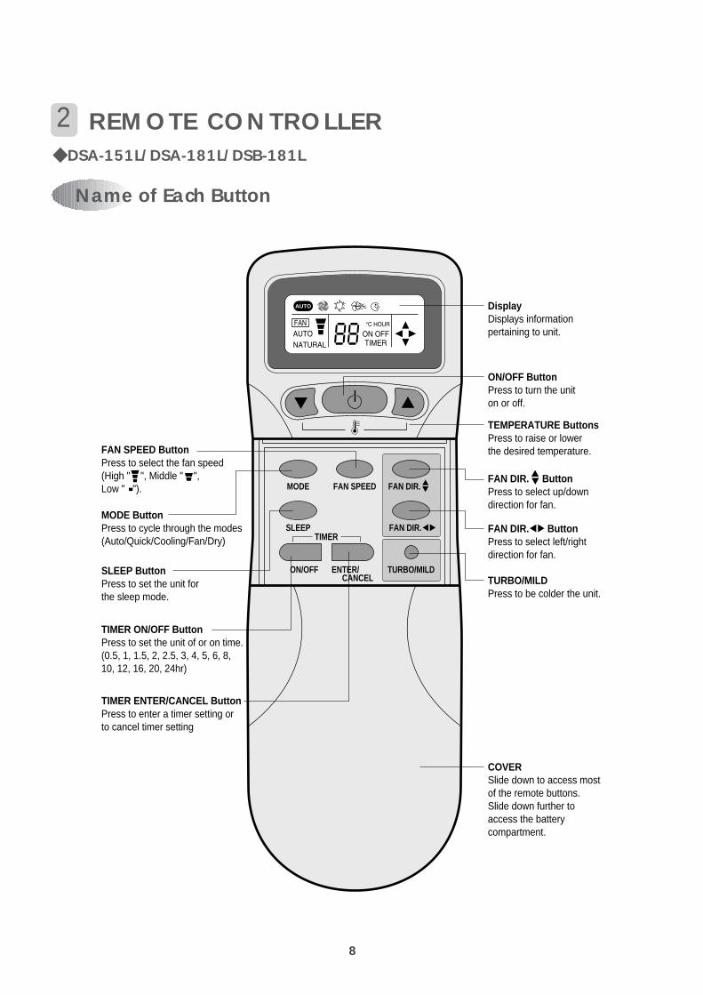
Name of Each Button
2 REMOTE CONTROLLER DSA-151L/DSA-181L/DSB-181L
MODE
SLEEP
ON/OFF
TIMER
ENTER/ CANCEL
FAN SPEED
TURBO/MILD
DisplayDisplays informationpertaining to unit.
TURBO/MILDPress to be colder the unit.
TIMER ENTER/CANCEL ButtonPress to enter a timer setting or to cancel timer setting
TIMER ON/OFF ButtonPress to set the unit of or on time.(0.5, 1, 1.5, 2, 2.5, 3, 4, 5, 6, 8, 10, 12, 16, 20, 24hr)
MODE ButtonPress to cycle through the modes(Auto/Quick/Cooling/Fan/Dry)
SLEEP ButtonPress to set the unit forthe sleep mode.
FAN DIR. ButtonPress to select up/downdirection for fan.
FAN DIR. ButtonPress to select left/rightdirection for fan.
ON/OFF ButtonPress to turn the uniton or off.
TEMPERATURE ButtonsPress to raise or lower the desired temperature.FAN SPEED Button
Press to select the fan speed (High " ", Middle " ", Low " ").
COVERSlide down to access mostof the remote buttons.Slide down further toaccess the batterycompartment.
AUTO
FAN DIR.
FAN DIR.
9
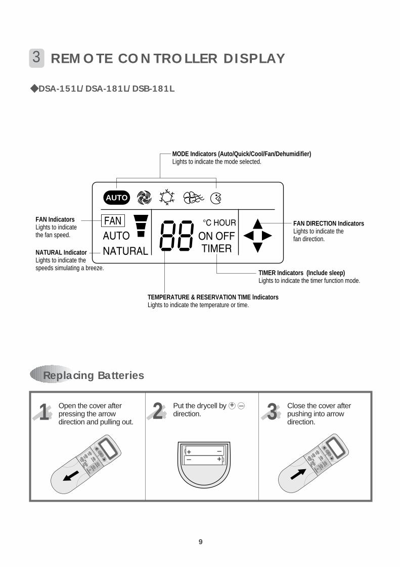
Replacing Batteries
3 REMOTE CONTROLLER DISPLAY
Open the cover afterpressing the arrowdirection and pulling out.
Put the drycell bydirection.
Close the cover afterpushing into arrowdirection.
1 2 3
DSA-151L/DSA-181L/DSB-181L
MODE Indicators (Auto/Quick/Cool/Fan/Dehumidifier)Lights to indicate the mode selected.
TIMER Indicators (Include sleep)Lights to indicate the timer function mode.
TEMPERATURE & RESERVATION TIME lndicatorsLights to indicate the temperature or time.
FAN DIRECTION IndicatorsLights to indicate thefan direction.
NATURAL IndicatorLights to indicate thespeeds simulating a breeze.
FAN IndicatorsLights to indicate the fan speed.
AUTO
+–
+ –
+ –

10
If you set time in OFF-Timer Mode, the unit will stop at the set time.
If you set time in ON-Timer Mode, the unit will run at the set time.
(1) Range of setting temperature: 18~32°C(2) Setting temperature: Operating temperature of compressor
(3) During the time of test operating, Fan (Indoor, Outdoor) and Compressor is running regardless of roomtemperature.
If the Indoor Unit Display receive the signal of Remote Controller, you can hear the signal "beep –" or "beep,beep".
OFF-Timer
4 DESCRIPTION OF FUNCTIONS
Unit ON
Unit OFF
SET Time HOUR
ON
OFF
ON-Timer
Unit ON
Unit OFF
SET Time HOUR
ON
OFF
Control of Room Temperature
Buzzer
COMP (ON)
(COOLING)
COMP (OFF)
-1˚C 0˚C Temperature(RT-DT)
Room temperatrue< setting temperatureCompressor OFF
Room temperature> setting temperafure Compressor ON
(
(

11
Fan Speed (Indoor Unit)
(1) Motor speed (high speed, normal speed, low speed).(2) Remote controller setting fan speed. (Auto, L, M, H, Natural)(3) Relation of operating mode between fan speed.
(4) Automatic OperationIf the unit is set in 'AUTO' mode, the unit operates automatically according to the room temperature to keep theroom temperature comfortable.
(COOLING)• DSA-151L/DSA-181L/DSB-181L
FAN ONLY COOLDEHUMI-
AUTO QuickDIFICATION
H H H X H H
M M M X M X
L L L X L X
Auto X Auto Auto Auto X
Natural Natural Natural X Natural X
0
LM
H
+1°C +2°C (RT-DT)

12
(1) When you are going to sleep, select sleep switch and the unit controls the room to the desired temperature. (The unit will not operate after 4 hour)
(2) For changing the temperature.
(3) To cancel sleep mode, press the SLEEP button again or press the MODE button once.: the SLEEPindicator will disappear in the display.
Sleep Mode
(1) When the remote controller is lost, damaged or the battery is discharged, the Emergency operation can beused to run the unit.
(2) The setting conditions of Emergency operation are as follows.• Operation mode: AUTO• Preset temperature: 26°C• Fan speed: AUTO
Emergency Operation
0 0.5 1.0 HOURSET TIME
Desired
Differencedesired temperaturebetween roomtemperature (°C) 0.5°C
0.5°C
0.5°C
Temperature

13
3 min. Time Delay of Compressor
In normal operation, there is a time delay of three minutes between turn off and turning back on including initialpower up.
When indoor fan motor is on, it always starts at normal speed and then it operates desired speed.
Indoor Fan Motor Starting
Frost Prevention of Indoor Unit
When the unit operates at low ambient temperature, frost may appear on the Evaporator. When the indoor coiltemperature is lower than 0°C at the end of 10 minutes of continuous compressor operation from the start, themicrocomputer of the unit stops the compressor to protect the unit from the frost. The control procedure forindoor coil freeze protection.
1) The compressor and outdoor fan turn off.2) Indoor fan operates according to user set speed.3) The normal operation returns when the indoor coil temperature is higher than 7°C or equal to 7°C.
0°C 7°C
Compressor and Outdoor Fan
OFF
ON
Set SpeedIndoor Fan
(Indoor coil temperature)
14
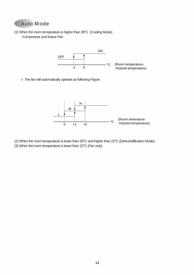
Auto Mode (1) When the room temperature is higher than 28°C (Cooling Mode)
! Compressor and lndoor Fan
@The fan will automatically operate as following Figure
(2) When the room temperature is lower than 28°C and higher than 22°C (Dehumidification Mode).(3) When the room temperature is lower than 22°C (Fan only).
-1 0°C
OFF
ON
(Room temperature- Desired temperature)
H
M
L
0 +1 +2°C
(Room temerature- Desired temperature)
15
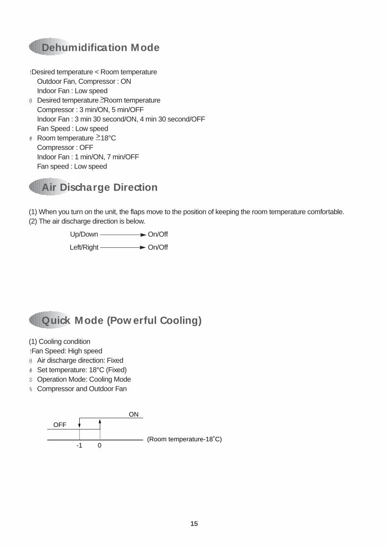
(1) Cooling condition! Fan Speed: High speed@ Air discharge direction: Fixed# Set temperature: 18°C (Fixed)$ Operation Mode: Cooling Mode% Compressor and Outdoor Fan
Quick Mode (Powerful Cooling)
-1
OFF
ON
(Room temperature-18˚C)0
Dehumidification Mode
Air Discharge Direction
(1) When you turn on the unit, the flaps move to the position of keeping the room temperature comfortable.(2) The air discharge direction is below.
Up/Down On/Off
Left/Right On/Off
! Desired temperature < Room temperatureOutdoor Fan, Compressor : ONIndoor Fan : Low speed
@ Desired temperature Room temperatureCompressor : 3 min/ON, 5 min/OFFIndoor Fan : 3 min 30 second/ON, 4 min 30 second/OFFFan Speed : Low speed
# Room temperature 18°CCompressor : OFFIndoor Fan : 1 min/ON, 7 min/OFFFan speed : Low speed
>
>

16
Self-Diagnostic Function
The control will contain diagnostic test to verify the integrity of the system.
(1)Error Code Display Pattern! ON LAMP: ON (Red) LED ON/OFF@Error Code (Display in Emergency Mode only)
ERROR CODE DISPLAY PATTEN ERROR CONTENTS
1Room air thermistor, connector
Indoor coil thermistor, connector
2Compressor, Electrical parts of
comp. Gas leak
8 seconds
0.5 second
8 seconds
0.5 second

17
4. WIRING DIAGRAM DSA-151L
OU
TD
OO
R U
NIT
IND
OO
R U
NIT

18
DSA-181L/DSB-181L

19
DSA-151L
Indoor
Unit
Outdoor
Unit
1 MAIN ELECTRIC PARTS
PART NAME PART CODE SPEC. QUANTITY REMARK
Fan Motor 3964330200 IC-9425 KH 6C 1
Fan Motor Capacitor 3106995010 1.2µF 450VAC 0.2A 1
Fuse 5FVGB0302R 250V 3A S/B 1
Fuse 5FVGD0402S 250V 4A 6ITS 1
Transformer 5EPK533110 220V/15V 1
Stepping Motor 1 3108004310 MP28GA (L=1300mm) 1
Stepping Motor 2 3108004300 MP-28GA (L=400mm) 2
Terminal Block 3108912320 SN-DBW-4P 1
Compressor 3100030AE0 RCA-150A001 1
Capacitor Dual 3109500100 370V 30/3µF 1
Fan Motor 3964320430 AM12DPD05 1
Power Relay 5SC0202700 G7L-2A-TUB 1
Terminal Block 3108912320 SN-DBW-4P 1

20
DSA-181L
Indoor
Unit
Outdoor
Unit
PART NAME PART CODE SPEC. QUANTITY REMARK
Fan Motor 3964330200 IC-9425 KH 6C 1
Fan Motor Capacitor 3106995010 1.2µF 450VAC 0.2A 1
Fuse 5FVGB0302R 250V 3A S/B 1
Fuse 5FVGD0402S 250V 4A 6ITS 1
Transformer 5EPK533110 220V/15V 1
Stepping Motor 1 3108004310 MP28GA (L=1300mm) 1
Stepping Motor 2 3108004300 MP-28GA (L=400mm) 2
Terminal Block 3108912320 SN-DBW-4P 1
Compressor 3107100000 ECB185211A 1
Capacitor Dual 3109500100 370V 30/3µF 1
Fan Motor 3964320430 AM12DPD05 1
Power Relay 5SC0202700 G7L-2A-TUB 1
Terminal Block 3108912320 SN-DBW-4P 1
21
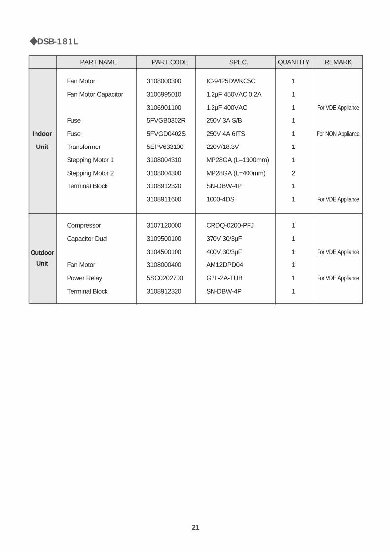
DSB-181L
Indoor
Unit
Outdoor
Unit
PART NAME PART CODE SPEC. QUANTITY REMARK
Fan Motor 3108000300 IC-9425DWKC5C 1
Fan Motor Capacitor 3106995010 1.2µF 450VAC 0.2A 1
3106901100 1.2µF 400VAC 1 For VDE Appliance
Fuse 5FVGB0302R 250V 3A S/B 1
Fuse 5FVGD0402S 250V 4A 6ITS 1 For NON Appliance
Transformer 5EPV633100 220V/18.3V 1
Stepping Motor 1 3108004310 MP28GA (L=1300mm) 1
Stepping Motor 2 3108004300 MP28GA (L=400mm) 2
Terminal Block 3108912320 SN-DBW-4P 1
3108911600 1000-4DS 1 For VDE Appliance
Compressor 3107120000 CRDQ-0200-PFJ 1
Capacitor Dual 3109500100 370V 30/3µF 1
3104500100 400V 30/3µF 1 For VDE Appliance
Fan Motor 3108000400 AM12DPD04 1
Power Relay 5SC0202700 G7L-2A-TUB 1 For VDE Appliance
Terminal Block 3108912320 SN-DBW-4P 1

22
5. REFRIGERANT CYCLE
INDOOR UNITEvaporator
Cross flow fan
Connecting pipe
Capillary tube
DryerCondenser
Propeller fanOUTDOOR UNIT
Refrigerant flow
Service valveService valve
Accumulator
Compressor
Note) If the pipe length exceeds the standard length, add 30g of refrigerant per extra meter.
ContentsModel Name
Capillary Tube
Charge Quantity
DSA-151L
ID2.0Ø x OD3.2Ø x L1200
1300 g
DSA-181L
ID1.78Ø x OD3.2Ø x L600
1500 g
DSB-181L
ID2.0Ø x OD3.2Ø x L650
1200 g

23
6. CONTROL BLOCK DIAGRAM
Relay RL1
Indoor fanmotor
PowerRelay
CompressorOutdoor
fan motor
TRIAC
DC12V
Operating Mode
Fan Speed
Timer Selection
Flap Position
Unit on lamp
Room air temp.
Indoor coil temp.
Quick lamp
Air-clean lamp
Remote
Emergency
Operation
Signalreceiver
Timer lamp
A/D converter lnitialization
Clock generation
DC power supply
Circuit forrelay driving
Circuit forTRIAC control
Transformer
Circuit for signal receiver
MICROCONTROLLER
Beeper
Circuit formotor driving
Steppingmotor 1,2
Temp. Setting
ON/OFF
SLEEP
Turbo/MILD
AC220VDC5V
DSA-151L/DSA-181L/DSB-181L

24
1
2
3
I.D.C
S
COMP
POWER RELAY
TERMINALBLOCK
TRANS-FORMER
CMC
Indoor UnitFan Motor
SWINGMOTOR
SWINGMOTOR2
ROOM AIRSENSOR
INDOOR COILSENSOR
SWINGMOTOR1
Display Part
Control Part
Signal Receiver
Pemote Controller
L N Y
COMP
FMC
7. ELECTRIC CIRCUIT DIAGRAM
DSA-151L/DSA-181L/DSB-181L
1 ELECTRIC CIRCUIT DIAGRAM

25
Description1. After the power ON/OFF button is pressed once, the relay and triac are turned ON or OFF per the remote
control setpoint.– TRIAC is controlled per the fan speed selection.– RELAY is controlled per the operation mode selection.
2. If the power ON/OFF button is pressed once more, the relay and triac are turn off and the unit stopsoperation.
3. The unit turns on or off according to the temperature setpoint by sensing the room air temperature throughthermistor.
4. If the fan speed selection is set to the auto position, the fan speed is automatically controlled according to thetemperature differance between room temperature and temperature setpoint.

2
2 PCB CIRCUIT DIAGRAM

26
27
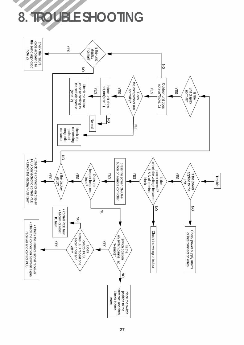
8. TROUBLE SHOOTING
Outdoor unit does
not run?(note. 1)
Does
the compressor run
normally?
Indoor unit doesnot run(note 1)
Check the failure
code according tothe self diagnostic
(note 2)
Is the unit display
morm
al?
check the failure code according to
the self-diagonostic(note 2)
Norm
alcheck the connecting
point ofm
agneticcontactor
YE
S
YE
S
YE
S
YE
S
NO
NO
YE
S
Trouble
Is the power
applied to theunit
Is the pow
er normal?
check the voltage between
L & N
of terminal
block
press the power O
N/O
FF button on rem
ote controller
Does the
beeper beep two
times?
Is the displayall off?
• Check the connector on display
PC
B connected to control P
CB
• Check the display P
CB
itself
Check pow
er supply mains
or interconnection wires
Check the w
iring of indoor
Is the sw
itch position on sw
itch pannel at "R
emote"
Does
control PC
B
status LED
repeat one second "on and
off"?
• control PC
B fault
• Micom
or reset IC
fault• Check the rem
ote signal receiver• C
heck the connection between signal
receiver and control PC
B
Place the sw
itchposition to the
"Rem
ote" and thenC
heck it once m
ore
YE
S
NO
YE
S
NO
NO
NO
NO
YE
S
YE
S
YE
S
YE
S
YE
S
NO
NO
NO
Is theunit display
normal?

28
Note 1)! Neither indoor unit nor outdoor unit runs.
Check the following points first. (There are following case in normal operation)a. Is the timer mode set the "timer ON".b. Is the timer mode set the "timer-OFF" and the time had passed?
@ Neither outdoor fan nor compressor runs while indoor fan runs.Check following points first. (There are following cases in normal operation)a. Is the temperature set point suitable?b. Has the 3 minutes time guard for compressor operated?
Note 2) Please refer to page 16, Self Diagnostic-function.
DSA-151L/DSA-181L/DSB-181L
1) Error Code 1! Check the connector of room air thermistor. (or connecting wire) @Check soldering of connecting on control P.C.B. (Error of soldering or short)# Check the resistance of room air thermistor.
2) Error Code 3 (Display Emergency mode)! When the compressor do not run.
i) Check the voltage between and of terminal block.(Indoor Unit, Outdoor Unit)
ii) Check connecting wire of indoor unit and outdoor unit. iii)Check relay KI on power P.C.B
@Check fixing of indoor coil thermistor.# Check the GAS LEAKAGE of the pipe.
YN
Self-Diagnostic Function

29
The power is applied to the unit
Check the voltage between and of terminal blockN
LCheck the
Breaker or Fuse
Self Diagnosticfunction is ON
Check according toself Diagnostic function
Control P.C.B defect
Check the indoor unit displayis the display all off?
Press the ON/OFF switch ofRemote Control
Is the indoor unit display all off?
Pull out the power plugand then insert the power plug
after 5 seconds
Control P.C.B is normalRecheck from the beginning
Rating voltage more than 90%
Rating voltage
under 90%
NO NO
NO
YESYES
Neither Indoor Unit nor Outdoor Unit Runs

30
Check rotation of indoor fan
Rotate indoor fan by hand
Check input Voltage of FanMotor connector at power P.C.B
Check the winding resistance of Indoor unit fan motor
Check the fan motor capacitor
Check the connecting wire of indoor fan motor
Run again
Check the Fan Motorbearing and fan
Check the power P.C.B.
The circuit for triac control
Change of fan motor
NO
Rating voltage
under 90%
Open or short
YES
Rating Voltage more than 90%
Normal
Outdoor Unit Runs but Indoor Unit Do Not Run

31
Outdoor Fan Do Not Run
Check the voltage between and of indoor unit terminalN
L
Check the voltage between and of outdoor unit terminalN
L
Check the voltage between and of outdoor unit terminalY
N
Check outdoor fan motor individually
Check theconnecting wire
Check theconnecting wire
Check the wiringand voltagewithin doors
Rating voltage
under 90%
Rating voltage
under 90%
Rating voltage
under 90%

32
- Check the following at cooling mode
Check the voltage between and of indoor unit terminalY
N
Check the voltage between and of outdoor unit terminalY
N
Check the magnetic contactor
Check the wiring of outdoor unit
Check the compressor(Check the winding resistance)
Check the compressor capacitor
Check the connectingwire between indoor
and outdoor.
Change the magneticcontactor.
Change thecompressor.
Check the control P.C.Bthe circuit for relay
driving.
Rating voltage
less than 90%
NG
Open or Short
Rating voltage
less than 90%
Rating voltage more than 90%
Rating voltage more than 90%
OK
Only Compressor Do not Run
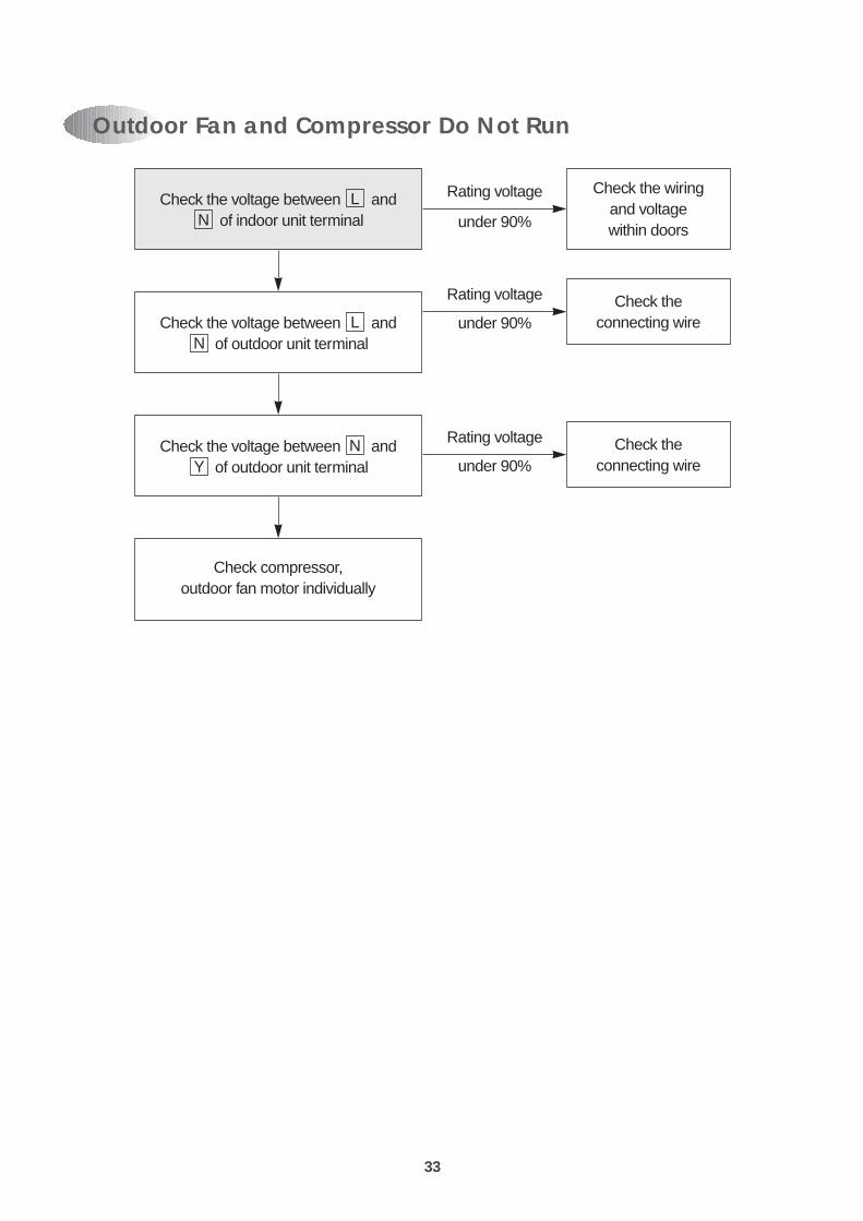
33
Check the voltage between and of indoor unit terminalN
L
Check the voltage between and of outdoor unit terminalN
L
Check the voltage between and of outdoor unit terminalY
N
Check compressor,outdoor fan motor individually
Check theconnecting wire
Check theconnecting wire
Check the wiringand voltagewithin doors
Rating voltage
under 90%
Rating voltage
under 90%
Rating voltage
under 90%
Outdoor Fan and Compressor Do Not Run

PCB DRIVING DESCRIPTION

35
Power Supply (1)
DESCRIPTION
DC Power Supply in circuit needs +12V and +5V. +12V is used for Compressor Driving Relay, Triac DrivingPhoto Triac, Buzzer Driving Swing, Sweep Motor, and LED Display. AC voltage of secondary PowerTransformer is rectified by Bridge Diode, and it is filtering by Main Condensor CE1.Filtered DC voltage is about +17V, is regulated +12V DC by Regulator IC7812.And it is regulated +5V DC by Regulator IC7805.VAR is surge filter and CE2, CE3, CC2, CC3 is Noise filter.
7805 7812
AC 220V
VAR
CC30.1 CC2
0.1CE2
470/16V CC1CE3
100/25V
3 1DC 12V
2
3 1
2
0.1µF/250VBD1
1000/35V
CE1+
+
POWERTRANS

36
Oscillation (2)
19
20 X-TAL8MHz
VDD-10%
VSS+10%
Fig 2-1
DESCRIPTION
Oscillatory Frequency drive Micom, it is made up 8MHz X-TAL oscillatory Freqency.Ocillatory wave is as following Fig 2-1.
37
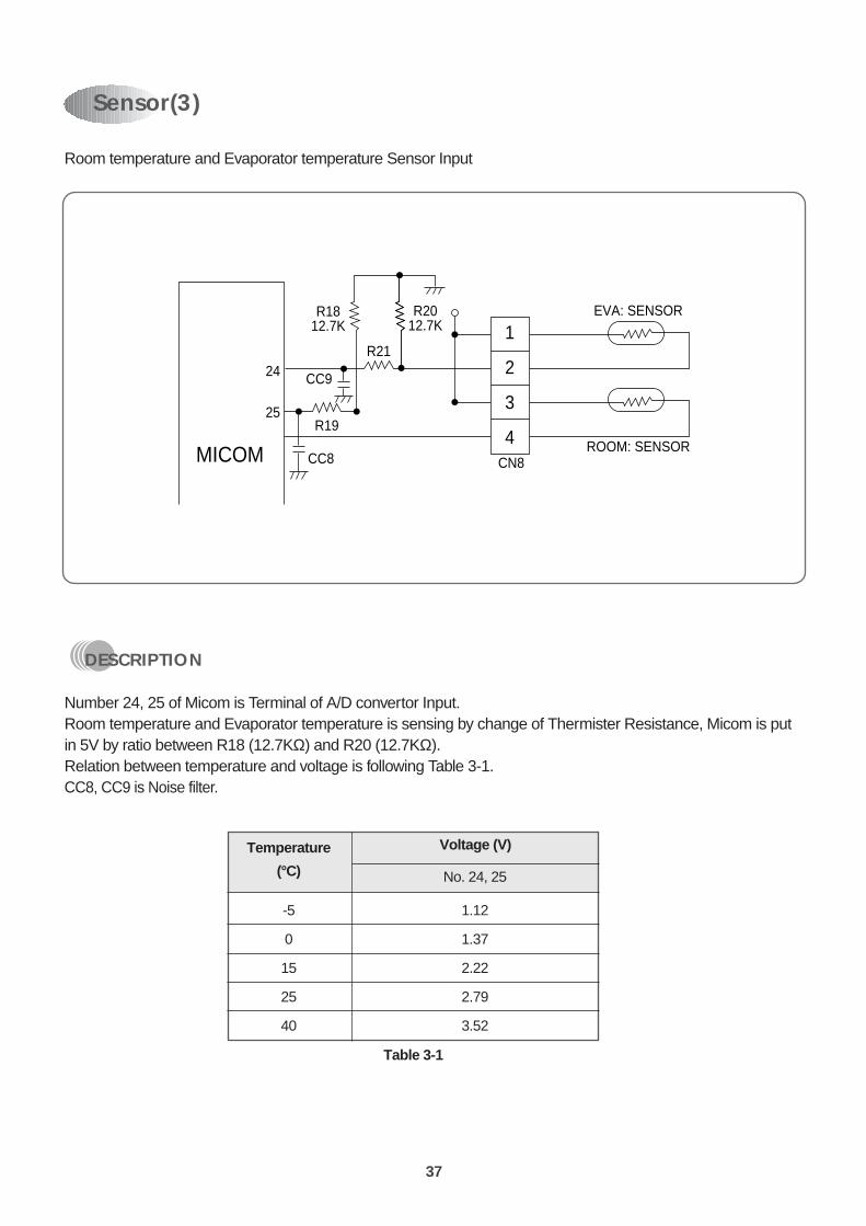
Room temperature and Evaporator temperature Sensor Input
DESCRIPTION
Number 24, 25 of Micom is Terminal of A/D convertor Input.Room temperature and Evaporator temperature is sensing by change of Thermister Resistance, Micom is putin 5V by ratio between R18 (12.7KΩ) and R20 (12.7KΩ).Relation between temperature and voltage is following Table 3-1.CC8, CC9 is Noise filter.
Temperature
(°C) No. 24, 25
-5 1.12
0 1.37
15 2.22
25 2.79
40 3.52
Voltage (V)
Table 3-1
Sensor(3)
24
25
R1812.7K
R2012.7K
CN8
R19
CC8
CC9
R21
EVA: SENSOR
ROOM: SENSOR
1
2
3
4MICOM
38
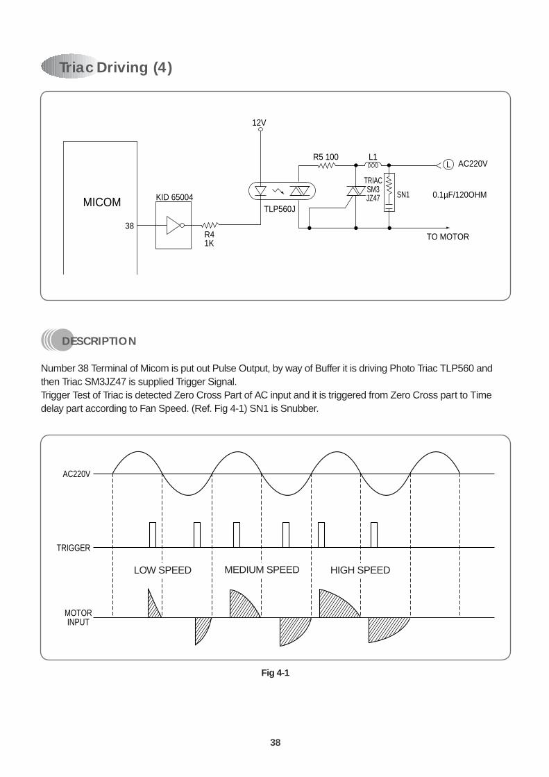
DESCRIPTION
Number 38 Terminal of Micom is put out Pulse Output, by way of Buffer it is driving Photo Triac TLP560 andthen Triac SM3JZ47 is supplied Trigger Signal.Trigger Test of Triac is detected Zero Cross Part of AC input and it is triggered from Zero Cross part to Timedelay part according to Fan Speed. (Ref. Fig 4-1) SN1 is Snubber.
KID 65004
38R41K
12V
R5 100 L1
TLP560J
TRIACSM3JZ47
AC220V
0.1µF/120OHM
TO MOTOR
SN1
L
MICOM
Triac Driving (4)
AC220V
TRIGGER
MOTORINPUT
LOW SPEED MEDIUM SPEED HIGH SPEED
Fig 4-1
LOW SPEED MEDIUM SPEED HIGH SPEED
39
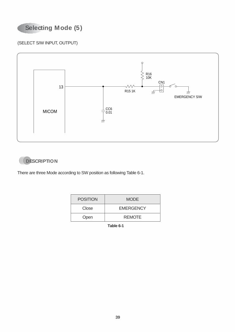
(SELECT S/W INPUT, OUTPUT)
DESCRIPTION
There are three Mode according to SW position as following Table 6-1.
Selecting Mode (5)
13
CC60.01
R15 1K
R1610K
CN1
EMERGENCY S/W
MICOM
POSITION MODE
Close EMERGENCY
Open REMOTE
Table 6-1

40
Micom Power Supply (6)
DESCRIPTION
MICOM Power is supplied 5V at Number 42 using Digital, Number 22 using Reference of A/D Converter.CE2 is Ripple filter and CC1 is Noise filter.
42
Vcc5V
10µF/16V
CE2
CC110422
21
MICOM

41
DESCRIPTION
Voltage less than about 0.8V put in Micom Terminal of Number 18 and then Micom reset. Reset IC detectPower ON and Voltage less than 4.2V, and then send Reset Signal. There is a Manual Reset S/W to resetmanually if necessary.
Reset (7)
R91K
CC3104
R105.6K
5V
18
5V
CE14.7µF/50
37042P
MICOM
1
2 RESET IC+
4.2V
H
L t
t
POWERON
Vcc (+5V)
DELAY TIMEFOR POWER ON
RESET

42
DESCRIPTION
Selecting Function is as following Table 9-1.
30
28
29
27
MICOM
CA1
JS3
JS5
R141K
Test
RA
R13 1K
R12 1K
R11 1K
JS4
Function Selecting (8)
JS6
JS5
JS4
JS3
SHORT
Skip
Mild
Heat
50Hz
OPEN
Comp err detect
High
Cool
60Hz
Table 9-1

43
1 INDOOR UNIT
9. DISASSEMBLY INSTRUCTIONS
PROCEDURES PHOTOS
1. Stop the Air conditioner and disconnect the power cord from the wall outlet.
2. Removing the Insert Grille and Frame.! Loosen three screws for fixing the the Insert Grille and Frame.
(Pull out the frame cap before loosening three screws) (Fig 1)@Loosen three screws at the Drain Pan.# Remove the Insert Grille and Frame.
3. Removing the Control Box.After doing above procedures:! Disconnect indoor room and coil thermistors. (Fig 3)@Disconnect the fan motor lead wire from connection at the main
PCB. (Fig 3)# Disconnect the swing motor connection wire.$ Loosen a screw for fixing ground wire.% Loosen two screws for fixing the body.
4. Removing the Drain Pan.After doing above procedures:! Loosen a screw for fixing body. (Fig 4)@Unhook the right part of Drain Pan.
5. Removing the Indoor Coil.After doing above procedures:! Loosen four screws for fixing indoor coil at left and right side. (Fig 5)@Loosen a screw for fixing the bracket tube at the back side. (Fig 6)# Remove the indoor coil. (Fig. 6-1)
6. Removing the fan motor.After doing above procedures:! Loosen two screws for fixing holder moter at left and right side.
(Fig 7, 8)@Loosen a screw for fixing fan motor and blower.# Renove the fan motor.
Fig 2
Fig 1
Fig 3
Fig 4
Fig 5
Fig 6
Fig 6-1

44
PROCEDURES PHOTOS
7. Removing the blower.After doing above procedures:! Loosen a screw for fixing holder bearing.@Remove the blower.
Fig 8
Fig 7

45
2 OUTDOOR UNIT¡ DSA-151L
PROCEDURES PHOTOS
1. Basic Procedures! Stop the air conditioner and pull out power plug from wall outlet.@Remove CABINET TOP COVER. (Loosen ten screws)# Remove CABINET SIDE COVER. (Loosen six screws)$ Remove CABINET FRONT. (Loosen six screws)
2. Removing Fan Motor (Fig 4)! Do basic procedure. (!~$)@ Loosen nut for fixing fan by spanner.# Remove spring washer and plain washer.$ Remove fan.% Remove fan stopper. Disconnect Motor lead wire from control box.
& Loosen four screws for fixing Motor bracket and then removethe Motor.
3. Removing Motor Capacitor and Compressor Capacitor! Do basic procedure.(!~$)@ Diconnect lead wire from the Motor capacitor and compressor
capacitor.# Loosen two screws for fixing the capacitor bracket.$ Remove Motor capacitor and compressor capacitor.
4. Removing Magnetic Contactor. (Fig 5)! Do basic procedure !~@.@Disconnect lead wire from Magnetic Contactor.# Remove Magnetic contactor. (Loosen four screws)
5. Removing Overload Protector. (Fig 6,7)! Do basic procedure !~#.@Remove terminal cover.# Disconnect lead wire from overload protector.$ Remove overload protector.
Fig 1
Fig 2
Fig 3
Fig 5
Fig 6
Fig 7
Fig 4

46
¡ DSA-181L/DSB-181L
PROCEDURES PHOTOS
1. Basic Procedures! Stop the air conditioner and pull out power plug from wall outlet.@Remove CABINET TOP COVER. (Loosen ten screws)# Remove CABINET SIDE COVER. (Loosen six screws)$ Remove CABINET FRONT. (Loosen six screws)
2. Removing Fan Motor (Fig 4)! Do basic procedure. (!~$)@ Loosen nut for fixing fan by spanner.# Remove spring washer and plain washer.$ Remove fan.% Remove fan stopper. Disconnect Motor lead wire from control box.
& Loosen four screws for fixing Motor bracket and then removethe Motor.
3. Removing Motor Capacitor and Compressor Capacitor.! Do basic procedure.(!~$)@ Diconnect lead wire from the Motor capacitor and compressor
capacitor.# Loosen two screws for fixing the capacitor bracket.$ Remove Motor capacitor and compressor capacitor.
4. Removing Magnetic Contactor. (Fig 5)! Do basic procedure !~@.@Disconnect lead wire from Magnetic Contactor.! Remove Magnetic contactor. (Loosen four screws)
Fig 1
Fig 2
Fig 3
Fig 5
Fig 4

47
3 EXPLODED DIAGRAM (Indoor Unit)¡ DSA-151L/DSA-181L/DSB-181L
48
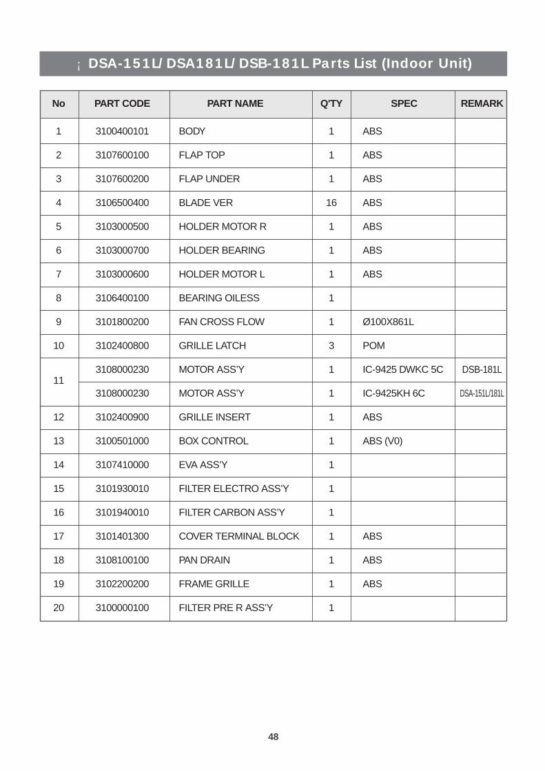
¡ DSA-151L/DSA181L/DSB-181L Parts List (Indoor Unit)
No PART CODE PART NAME Q'TY SPEC REMARK
1 3100400101 BODY 1 ABS
2 3107600100 FLAP TOP 1 ABS
3 3107600200 FLAP UNDER 1 ABS
4 3106500400 BLADE VER 16 ABS
5 3103000500 HOLDER MOTOR R 1 ABS
6 3103000700 HOLDER BEARING 1 ABS
7 3103000600 HOLDER MOTOR L 1 ABS
8 3106400100 BEARING OILESS 1
9 3101800200 FAN CROSS FLOW 1 Ø100X861L
10 3102400800 GRILLE LATCH 3 POM
113108000230 MOTOR ASS’Y 1 IC-9425 DWKC 5C DSB-181L
3108000230 MOTOR ASS’Y 1 IC-9425KH 6C DSA-151L/181L
12 3102400900 GRILLE INSERT 1 ABS
13 3100501000 BOX CONTROL 1 ABS (V0)
14 3107410000 EVA ASS’Y 1
15 3101930010 FILTER ELECTRO ASS’Y 1
16 3101940010 FILTER CARBON ASS’Y 1
17 3101401300 COVER TERMINAL BLOCK 1 ABS
18 3108100100 PAN DRAIN 1 ABS
19 3102200200 FRAME GRILLE 1 ABS
20 3100000100 FILTER PRE R ASS’Y 1

49
No PART CODE PART NAME Q'TY SPEC REMARK
21 3100000200 FILTER PRE L ASS’Y 1
22 3102900100 HINGE R-A 1 POM
23 3102900300 HINGE L-A 1 POM
24 3100001000 M-PCB ASS’Y 1
25 3107800100 LINK VER CAM 1 P.O.M
26 3104395400 F-PCB ASS’Y 1
27 3108004300 MOTOR STEPPING 2 MP28GA/GSP-24SW-06/ST-28 L=400mm
28 3108912320 TERMINAL BLOCK 1 DBW-4P
29 3107400300 EVA BRKT L 1 SGCC T1.0
30 3107800200 LINK VER A 1 ABS
31 3107800400 LINK VER C 1 ABS
32 3107500200 EMBLEM 1 URETANE
33 3105500400 PLT WINDOW SWITCH 1
34 3104500300 PLATE MOUNTING 1 SGCC T0.8
35 3108004310 MOTOR STEPPING 1 MP28GA/GSP-24SW-06/ST-28 L=1300mm
50
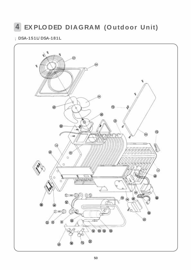
4 EXPLODED DIAGRAM (Outdoor Unit)¡ DSA-151L/DSA-181L
51
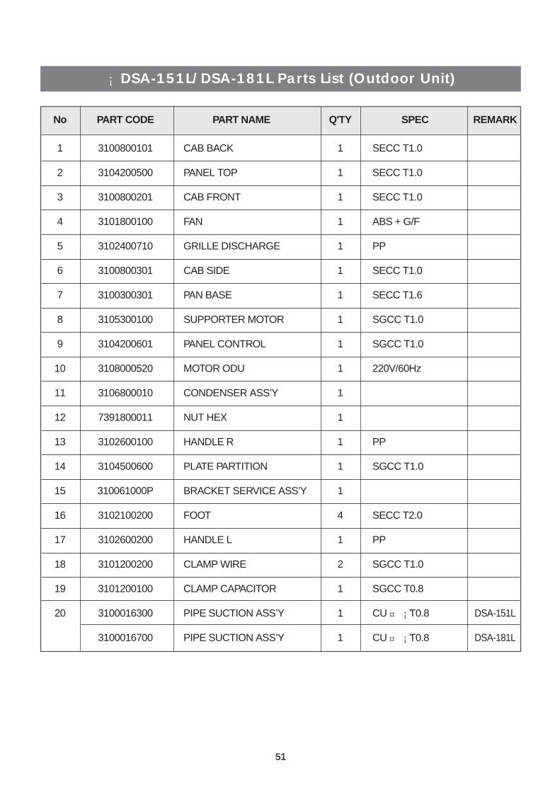
¡ DSA-151L/DSA-181L Parts List (Outdoor Unit)
No PART CODE PART NAME Q'TY SPEC REMARK
1 3100800101 CAB BACK 1 SECC T1.0
2 3104200500 PANEL TOP 1 SECC T1.0
3 3100800201 CAB FRONT 1 SECC T1.0
4 3101800100 FAN 1 ABS + G/F
5 3102400710 GRILLE DISCHARGE 1 PP
6 3100800301 CAB SIDE 1 SECC T1.0
7 3100300301 PAN BASE 1 SECC T1.6
8 3105300100 SUPPORTER MOTOR 1 SGCC T1.0
9 3104200601 PANEL CONTROL 1 SGCC T1.0
10 3108000520 MOTOR ODU 1 220V/60Hz
11 3106800010 CONDENSER ASS’Y 1
12 7391800011 NUT HEX 1
13 3102600100 HANDLE R 1 PP
14 3104500600 PLATE PARTITION 1 SGCC T1.0
15 310061000P BRACKET SERVICE ASS’Y 1
16 3102100200 FOOT 4 SECC T2.0
17 3102600200 HANDLE L 1 PP
18 3101200200 CLAMP WIRE 2 SGCC T1.0
19 3101200100 CLAMP CAPACITOR 1 SGCC T0.8
20 3100016300 PIPE SUCTION ASS’Y 1 CU ¡ T0.8 DSA-151L
3100016700 PIPE SUCTION ASS’Y 1 CU ¡ T0.8 DSA-181L¤
¤

52
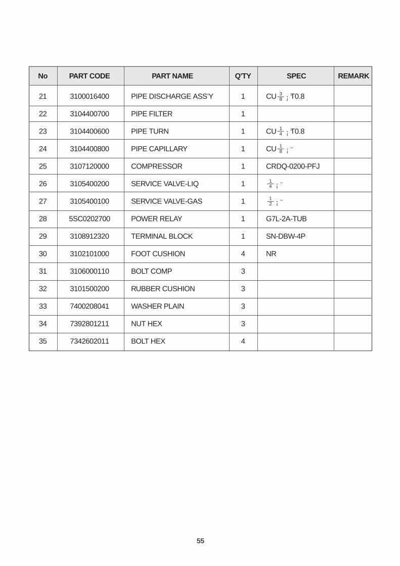
No PART CODE PART NAME Q'TY SPEC REMARK
213100016200 PIPE DISCHARGE ASS’Y 1 CU ¡ T0.8 DSA-151L
3100016600 PIPE DISCHARGE ASS’Y 1 CU ¡ T0.8 DSA-181L
22 3104400700 PIPE FILTER 1
23 3104400600 PIPE TURN 1 CU ¡ T0.8
24 3104400800 PIPE CAPILLARY 1 CU ¡¨
253100030AE0 COMPRESSOR ASS’Y 1 RCA150A001 DSA-151L
3107120010 COMPRESSOR ASS’Y 1 ECB 185211A DSA-181L
26 3105400200 SERVICE VALVE-LIQ 1 ¡¨
27 3105400100 SERVICE VALVE-GAS 1 ¡¨
28 5SC0202700 POWER RELAY 1 G7L-2A-TUB
29 3108912320 TERMINAL BLOCK 1 SN-DBW-4P
30 3102101000 FOOT CUSHION 4 NR
31 3107140010 COMP BOLT 3
32 3101500200 RUBBER CUSHION 3
33 7400208411 WASHER PLAIN 3
34 7392801211 NUT LOCK 3
35 7342602011 BOLT HEX 4
36 7112501211 SCREW TAPPING 4
37 8112401211 SCREW TAPPING 10
12
14
18
14
516
516

53
¡ DSB-181L
u

54
¡ DSB-181L Parts List (Outdoor Unit)
No PART CODE PART NAME Q'TY SPEC REMARK
1 3100800101 CAB BACK 1 SECC T1.0
2 3104200500 PANEL TOP 1 SECC T1.0
3 3100800201 CAB FRONT 1 SECC T1.0
4 3101800100 FAN 1 ABS + G/F
5 3102400710 GRILLE DISCHARGE 1 PP
6 3100800301 CAB SIDE 1 SECC T1.0
7 3100300301 PAN BASE 1 SECC T1.6
8 3105300100 SUPPORTER MOTOR 1 SGCC T1.0
9 3104210010 PANEL CONTROL 1 SGCC T1.0
3100039210 PANEL CONTROL 1 SGCC T1.0
10 3108000400 MOTOR ODU 1 220V/50Hz
11 3106800020 CONDENSER ASS’Y 1
12 7391800011 NUT HEX 1
13 3102600100 HANDLE R 1 PP
14 3104500600 PLATE PARTITION 1 SGCC T1.0
15 3100600000 BRACKET SERVICE ASS’Y 1
16 3102100200 FOOT 4 SECC T2.0
17 3102600200 HANDLE L 1 PP
18 3101200200 CLAMP WIRE 2 SGCC T1.0
3101202000 CLAMP CORD 1 NYLON 66
19 3101200100 CLAMP CAPACITOR 1 SGCC T0.8
20 3100016700 PIPE SUCTION ASS’Y 1 CU ¡ T0.8¤
DSB-181L forVDE Appliance
DSB-181L forVDE Appliance
55
No PART CODE PART NAME Q'TY SPEC REMARK
21 3100016400 PIPE DISCHARGE ASS’Y 1 CU ¡ T0.8
22 3104400700 PIPE FILTER 1
23 3104400600 PIPE TURN 1 CU ¡ T0.8
24 3104400800 PIPE CAPILLARY 1 CU ¡¨
25 3107120000 COMPRESSOR 1 CRDQ-0200-PFJ
26 3105400200 SERVICE VALVE-LIQ 1 ¡¨
27 3105400100 SERVICE VALVE-GAS 1 ¡¨
28 5SC0202700 POWER RELAY 1 G7L-2A-TUB
29 3108912320 TERMINAL BLOCK 1 SN-DBW-4P
30 3102101000 FOOT CUSHION 4 NR
31 3106000110 BOLT COMP 3
32 3101500200 RUBBER CUSHION 3
33 7400208041 WASHER PLAIN 3
34 7392801211 NUT HEX 3
35 7342602011 BOLT HEX 4
12
14
18
14
38

56
5 CONTROL BOX ASSEMBLY
¡ DSA-151L/DSA-181L/DSB-181L
1CONTROL BOX ASSY

57
¡ DSA-151L/DSA-181L/DSB-181L
No PART NAME SPEC Q’TY PART CODE REMARK
1 CONTROL BOX ASS’YDSA-151L/DSA-181L 1 3100058320
DSB-181L 1 3100058210
2 BOX CONTROL-2 ABS (VERSION2) 1 3100506900
3 PCB TRANS ASS’YDWA-5423 1 5EPK633110
DWA-220V 1 5EPV633110
4 SCREW TAPPING T2S TRS 4X12 MFZN 3 7122401211
5 CAPACITOR IDM EAF-45125 (1.2µF/450V) 1 3106900210
6 SCREW TAPPING T2S TRS 4X24 MFZN 1 7141402411
7 TERMINAL BLOCK SN-DBW-4P 1 3108912320
8 SCREW TAPPING T2S TRS 3X16 MFZN 2 7111301611
9 HARNESS POWER UL1015 #16/18 1 3102704010
10 HARNESS EARTH UL1015 #18 1 3102797910
11 HARNESS COMP SIGNAL UL1015 #18 1 3102704410
12 POWER CORDWS-93 (250V 10/16A) 1 31013A24B1
13 CABLE CORD DA-5N 1 3101200300
14 CONTROL PCB ASS’YDSA-151L/DSA-181L 1 3104300120
DSB-181L (COOL/50Hz) 1 3104300110
15 HARNESS CONNECTING UL 1007 #26 1 3102704900
16 POWER PCB ASS’Y DSA-151L/DSA-181L/DSB-181L 1 3104300210
17 LED PCB ASS’Y 15/18K 1 3104300300
18 SWITCH PCB ASS’Y 15/18K 1 3104300400
19 SENSOR ID ASS’Y PEM-KD43C-D1 1 3104896000
20 HARNESS LED PCB UL 1007 #26 1 3102704510
21 HARNESS SWITCH PCB UL 1007 #26 1 3102707000
22 KNOB SWITCH ABS 1 3103400200

DAEWOO ELECTRONICS CO., LTD.686, AHYEON-DONG MAPO-GU SEOUL, KOREAC.P.O. BOX 8003 SEOUL, KOREATELEX: DWELEC K28177-8CABLE: “DAEWOOELEC”FAX: 02) 360-8184TEL: 02) 360-8182/8178~9http://www.dwe. daewoo.co.kr
PRINTED DATE: APR.1999
60
Service ManualModel: DSA-151L
DSA-181L
DSB-181L
DAEWOO ELECTRONICS CO., LTD.OVERSEAS SERVICE DEFT.