
DS6000 Host Systems Attachment Guide
276
IBM System Storage DS6000 Host Systems Attachment Guide Version 1 Release 2 GC26-7923-00
-
Upload
khangminh22 -
Category
Documents
-
view
1 -
download
0
Transcript of DS6000 Host Systems Attachment Guide

IBM System Storage DS6000
Host Systems Attachment Guide
Version 1 Release 2
GC26-7923-00
���


IBM System Storage DS6000
Host Systems Attachment Guide
Version 1 Release 2
GC26-7923-00
���

Note:
Before using this information and the product it supports, read the information in the Safety and environmental notices
and Notices sections.
First Edition (September 2006)
This edition replaces GC26-7680-05 and all previous versions of GC26-7680.
© Copyright International Business Machines Corporation 2004, 2006. All rights reserved.
US Government Users Restricted Rights – Use, duplication or disclosure restricted by GSA ADP Schedule Contract
with IBM Corp.

Contents
Figures . . . . . . . . . . . . . . vii
Tables . . . . . . . . . . . . . . . ix
About this guide . . . . . . . . . . . xi
Notices and publication information xiii
Safety notices . . . . . . . . . . . . . xiii
Environmental notices . . . . . . . . . . xiii
Product recycling and disposal . . . . . . xiii
Battery return program . . . . . . . . . xiv
Conventions used in this guide . . . . . . . . xv
Related information . . . . . . . . . . . xvi
DS6000 series library . . . . . . . . . . xvi
Other IBM publications . . . . . . . . . xvii
Ordering IBM publications . . . . . . . . xxi
Web sites . . . . . . . . . . . . . . . xxii
How to send your comments . . . . . . . . xxiii
Summary of Changes for
GC26-7923-00 IBM System Storage
DS6000 Host Systems Attachment
Guide . . . . . . . . . . . . . . . xxv
Chapter 1. Introduction . . . . . . . . 1
Introduction to host attachment . . . . . . . . 1
General requirements for attaching a host system 1
Downloading and installing a host adapter driver 2
IBM System Storage Multipath Subsystem Device
Driver . . . . . . . . . . . . . . . 5
FlashCopy and Remote Mirror and Copy
attachment restrictions . . . . . . . . . . 6
DS6000 fabric zoning . . . . . . . . . . 6
Fibre-channel host attachment . . . . . . . 7
Interfaces of the DS6000 . . . . . . . . . . 14
IBM System Storage DS Storage Manager . . . 14
The DS command-line interface . . . . . . . 19
DS open application programming interface . . 21
Introduction to the IBM System Storage DS6000
series . . . . . . . . . . . . . . . . 21
Overview of the DS6000 series models . . . . 22
Management console requirements . . . . . 25
Performance features . . . . . . . . . . 26
RAID implementation . . . . . . . . . . 28
Licensed functions . . . . . . . . . . . 28
DS6000 Interfaces . . . . . . . . . . . 29
Host systems attachment overview . . . . . 33
IBM System Storage Resiliency Family . . . . 33
Logical configuration overview . . . . . . . 39
Host systems that DS6000 series supports . . . 42
Chapter 2. Apple Macintosh host
attachment . . . . . . . . . . . . . 45
Chapter 3. Fujitsu PRIMEPOWER host
attachment . . . . . . . . . . . . . 47
Locating the WWPN for a Fujitsu PRIMEPOWER
host . . . . . . . . . . . . . . . . . 47
Installing the Emulex adapter for a PRIMEPOWER
host . . . . . . . . . . . . . . . . . 47
Parameter settings for the Emulex LP9002L
adapter . . . . . . . . . . . . . . . 48
Setting parameters for Emulex adapters . . . . 49
Configuring host device drivers for a
PRIMEPOWER host . . . . . . . . . . 49
Chapter 4. Hewlett-Packard Server
(HP-UX) host attachment . . . . . . . 53
Locating the WWPN for a Hewlett-Packard host . . 53
Setting the queue depth for an HP-UX host . . . . 54
Configuring clustering on a HP-UX host . . . . . 54
Chapter 5. HP AlphaServer OpenVMS
host attachment . . . . . . . . . . . 57
Confirming the installation of the OpenVMS
operating system . . . . . . . . . . . . 58
Installing the KGPSA-xx adapter card in an
OpenVMS host system . . . . . . . . . . 58
Setting the mode for the KGPSA-xx host adapter
in an OpenVMS host system . . . . . . . . 59
Locating the WWPN for a Hewlett-Packard
AlphaServer host . . . . . . . . . . . . 60
OpenVMS UDID Support . . . . . . . . . . 60
OpenVMS LUN 0 - command console LUN . . . 62
Confirming fibre-channel switch connectivity for
OpenVMS . . . . . . . . . . . . . . . 63
How to access the storage unit volumes from an
OpenVMS host . . . . . . . . . . . . . 63
OpenVMS fibre-channel restrictions . . . . . . 64
Chapter 6. HP AlphaServer Tru64 UNIX
host attachment . . . . . . . . . . . 67
Confirming the installation of the Tru64 UNIX
operating system . . . . . . . . . . . . 68
Installing the KGPSA-xx adapter card in an Tru64
UNIX host system . . . . . . . . . . . . 68
Setting the mode for the KGPSA-xx host adapter . . 69
Locating the WWPN for a Hewlett-Packard
AlphaServer host . . . . . . . . . . . . 69
Configuring a HP AlphaServer Tru64 UNIX host . . 70
Confirming fibre-channel switch connectivity for
Tru64 UNIX . . . . . . . . . . . . . 70
Confirming fibre-channel storage connectivity for
Tru64 UNIX . . . . . . . . . . . . . 71
Tru64 UNIX UDID hexadecimal representations 72
Preparing to boot from the storage unit for the
Tru64 UNIX host system . . . . . . . . . 72
© Copyright IBM Corp. 2004, 2006 iii

Configuring kernel SCSI parameters on an HP
AlphaServer Tru64 UNIX host system . . . . 73
Verifying fibre-channel attachment to Tru64
UNIX . . . . . . . . . . . . . . . 74
Configuring the storage for fibre-channel Tru64
UNIX hosts . . . . . . . . . . . . . . 75
Removing persistent reserves for Tru64 UNIX 5.x . . 76
Limitations for Tru64 UNIX . . . . . . . . . 78
Configuring AdvFS parameters on an HP
AlphaServer Tru64 UNIX host system . . . . 78
Chapter 7. IBM eServer iSeries host
attachment . . . . . . . . . . . . . 81
Locating the WWPN for an IBM eServer iSeries host 81
LUN considerations for IBM iSeries hosts . . . . 82
Switch support for IBM iSeries hosts . . . . . . 83
Recommended configurations for IBM iSeries hosts 83
Running the Linux operating system on an IBM i5
server . . . . . . . . . . . . . . . . 86
Running Linux in a guest partition on an IBM i5
server . . . . . . . . . . . . . . . 86
Planning to run Linux in a hosted or nonhosted
guest partition . . . . . . . . . . . . 87
Creating a guest partition to run Linux . . . . 87
Managing Linux in a guest partition . . . . . 88
Ordering or upgrading a server to run a guest
partition . . . . . . . . . . . . . . 89
Chapter 8. IBM eServer pSeries or IBM
RS/6000 host attachment . . . . . . . 91
Installing the host attachment package on IBM
pSeries AIX hosts from the CDROM . . . . . . 91
Installing the host attachment package on IBM
pSeries AIX hosts from the server . . . . . . . 92
Locating the WWPN for an IBM eServer pSeries or
an RS/6000 host . . . . . . . . . . . . . 93
Attaching a pSeries or RS/6000 host . . . . . . 93
Verifying the AIX host system configuration on a
pSeries . . . . . . . . . . . . . . . 94
Making SAN changes for IBM pSeries hosts . . 95
Support for fibre-channel boot on a pSeries host . . 95
Fibre-channel boot considerations for IBM pSeries
hosts . . . . . . . . . . . . . . . 96
pSeries host boot device installation and disk
configuration . . . . . . . . . . . . . 96
Attaching to multiple RS/6000 or pSeries hosts
without a HACMP host . . . . . . . . . . 97
Considerations for multiple RS/6000 or pSeries
hosts without HACMP . . . . . . . . . 97
Saving data on the storage unit when attaching
multiple RS/6000 or pSeries hosts . . . . . . 97
Restoring data when attaching multiple RS/6000
or pSeries . . . . . . . . . . . . . . 98
Installing the subsystem device driver on an IBM
pSeries host running Linux . . . . . . . . . 98
Hardware requirements for the subsystem device
driver on a pSeries host running Linux . . . . 99
Preparing to install the subsystem device driver
on a pSeries host running Linux . . . . . . 100
Installing the Subsystem Device Driver on a
pSeries host running Linux . . . . . . . . 100
Upgrading the Subsystem Device Driver for the
Linux operating system on the pSeries host . . 101
Verifying the subsystem device driver on a
pSeries host running Linux . . . . . . . . 101
Configuring the Subsystem Device Driver . . . 102
Chapter 9. IBM eServer zSeries or IBM
S/390 host attachment . . . . . . . 103
FICON-attached S/390 and zSeries hosts overview 103
Attaching a zSeries host with FICON adapters 104
Linux for S/390 and zSeries . . . . . . . . 105
Running Linux on an S/390 or zSeries host . . 105
Attaching fibre-channel adapters to zSeries hosts
running Linux . . . . . . . . . . . . 106
Registered state-change notifications (RSCNs) on
zSeries hosts . . . . . . . . . . . . . . 111
Analyzing service information messages for S/390
and zSeries systems . . . . . . . . . . . 112
Chapter 10. IBM NAS Gateway 500
host attachment . . . . . . . . . . 113
Locating the WWPN on a NAS Gateway 500 host
system . . . . . . . . . . . . . . . . 113
Obtaining NAS Gateway 500 WWPNs using a
Web browser . . . . . . . . . . . . 113
Obtaining WWPNs through the command-line
interface . . . . . . . . . . . . . . 113
Chapter 11. IBM SAN File System host
attachment . . . . . . . . . . . . 115
Chapter 12. IBM SAN Volume
Controller host attachment . . . . . 117
Chapter 13. Intel or AMD running
Linux host attachment . . . . . . . 119
Installing an Emulex adapter on an Intel or AMD
host running Linux . . . . . . . . . . . 120
Installing and updating an Emulex driver on an
Intel or AMD host running Linux . . . . . . 121
Configuring and troubleshooting an Emulex
adapter on Linux . . . . . . . . . . . . 122
Installing a QLogic adapter on an Intel or AMD
host system running Linux . . . . . . . . . 123
Installing and updating a QLogic driver on an
Intel or AMD host running Linux . . . . . 125
Configuring and Troubleshooting a QLogic
adapter on Linux . . . . . . . . . . . 125
Locating the WWPN for a Linux host . . . . . 126
Managing SCSI disk connectivity . . . . . . . 127
Linux SCSI subsystem overview . . . . . . 127
LUN identification for the Linux host system 128
Dynamic SAN fabric reconfiguration . . . . 129
LUN detection procedures . . . . . . . . 131
Linux device naming . . . . . . . . . . 133
SCSI disk limitations: Defining the number of
disk devices on Linux . . . . . . . . . 135
iv DS6000 Host Systems Attachment Guide
|||
| | |

SCSI disk problem identification and resolution 136
Creating a DS6000 file system and partitions for an
Intel host running Linux . . . . . . . . . . 136
Assigning the system ID to the partition of an Intel
or AMD host running Linux . . . . . . . . 137
Creating a file system for an Intel or AMD host
running Linux . . . . . . . . . . . . . 138
Fibre-channel boot on an Intel or AMD host
running Linux . . . . . . . . . . . . . 139
Creating a modules disk for SUSE Linux
Enterprise Server 9.0 . . . . . . . . . . 139
Installing Linux over the SAN without an IBM
subsystem device driver . . . . . . . . . 139
Updating a module without an IBM subsystem
device driver . . . . . . . . . . . . 141
Installing Linux over the SAN with an IBM
subsystem device driver . . . . . . . . . 141
Chapter 14. Intel running VMware ESX
server host attachment . . . . . . . 147
Installing the Emulex adapter for an Intel host
running VMware ESX Server . . . . . . . . 147
Installing the QLogic adapter and driver for an
Intel host running VMware ESX Server . . . . . 148
Defining the number of disks devices on VMware
ESX Server . . . . . . . . . . . . . . 149
SCSI disk considerations for an Intel host running
VMware ESX server . . . . . . . . . . . 149
LUN identification for the VMware ESX console 150
Disk device discovery on VMware ESX . . . . 152
Persistent binding . . . . . . . . . . . 153
Configuring an Intel host running VMware ESX
Server . . . . . . . . . . . . . . . . 153
Partitioning storage unit disks for an Intel host
running VMware ESX Server . . . . . . . 153
Creating a file system for an Intel host running
VMware ESX Server . . . . . . . . . . 154
Copy Services considerations for VMware ESX
Servers . . . . . . . . . . . . . . . 155
Chapter 15. Intel or AMD running
Microsoft Windows 2000 or 2003 host
attachment . . . . . . . . . . . . 157
Installing an Emulex adapter and driver for
Windows 2000 or 2003 . . . . . . . . . . 157
Installing a Netfinity adapter and driver for
Windows 2000 or 2003 . . . . . . . . . . 161
Documentation that comes with your Netfinity
adapter . . . . . . . . . . . . . . 162
Installing a QLogic adapter and driver for
Windows 2000 or 2003 . . . . . . . . . . 163
Updating the Windows 2000 or 2003 device driver 164
Locating the WWPN for a Windows 2000 or 2003
host . . . . . . . . . . . . . . . . 164
Verifying that Windows 2000 or 2003 is configured
for storage . . . . . . . . . . . . . . 165
Setting the TimeOutValue registry for Windows
2000 or 2003 . . . . . . . . . . . . . . 165
Installing remote fibre-channel boot support for a
Windows 2000 or 2003 host system . . . . . . 166
Configure zoning and obtain storage . . . . 166
Flash QLogic host adapter . . . . . . . . 167
Configure QLogic and Emulex host adapters 167
Windows 2000 and 2003 installation . . . . . 167
Windows 2000 and 2003 Post Installation . . . 168
Chapter 16. Intel running Novell
NetWare host attachment . . . . . . 169
Installing an Emulex adapter and driver for a
Novell NetWare host . . . . . . . . . . . 169
Installing a QLogic adapter and driver for a Novell
NetWare host . . . . . . . . . . . . . 170
Installing a QLogic adapter driver for a Novell
NetWare host . . . . . . . . . . . . 171
Locating the WWPN for a QLogic adapter on a
Novell NetWare host . . . . . . . . . . 172
Chapter 17. Silicon Graphics host
attachment . . . . . . . . . . . . 173
Checking the version of the IRIX operating system 174
Installing a fibre-channel adapter card for the SGI
host system . . . . . . . . . . . . . . 174
Verifying the installation of a fibre-channel
adapter card for SGI . . . . . . . . . . 174
Configuring the fibre-channel adapter drivers
for SGI . . . . . . . . . . . . . . 174
Installing an optical cable for SGI in a
switched-fabric topology . . . . . . . . . 175
Installing an optical cable for SGI in an arbitrated
loop topology . . . . . . . . . . . . . 175
Confirming switch connectivity for SGI . . . . . 175
Displaying zoning information for the switch . . . 176
Locating the WWPN for an SGI host . . . . . 177
Confirming storage connectivity on a SGI host . . 177
Confirming storage connectivity for SGI in a
switched-fabric topology . . . . . . . . 178
Confirming storage connectivity for SGI in a
fibre-channel arbitrated loop topology . . . . 178
Configuring the storage unit for host failover using
IRIX multipathing . . . . . . . . . . . . 179
Confirming the availability of failover . . . . 179
Making a connection through a switched-fabric
topology . . . . . . . . . . . . . . 179
Making a connection through an arbitrated-loop
topology . . . . . . . . . . . . . . 180
Switching I/O operations between the primary
and secondary paths . . . . . . . . . . 180
Configuring storage in a switched fabric or
arbitrated loop topology . . . . . . . . . . 180
Configuring storage in a switched fabric
topology . . . . . . . . . . . . . . 180
Configuring storage in an arbitrated loop
topology . . . . . . . . . . . . . . 182
Chapter 18. Sun host attachment . . . 185
Installing an AMCC PCI adapter and driver on a
Sun host . . . . . . . . . . . . . . . 186
Installing an Emulex adapter on a Sun host . . . 186
Installing a Sun adapter and driver on a Sun host
system . . . . . . . . . . . . . . . 186
Contents v
| | |

Installing a QLogic adapter and driver on the Sun
host . . . . . . . . . . . . . . . . 187
Installing the QLogic adapter driver package for
Sun . . . . . . . . . . . . . . . . 188
Configuring host device drivers for Sun . . . . 188
Parameter settings for the AMCC adapters for
the Sun host system . . . . . . . . . . 190
Setting the parameters for AMCC adapters on a
SUN host system . . . . . . . . . . . 192
Parameter settings for the Emulex adapters for
the Sun host system . . . . . . . . . . 193
Setting the parameters for Emulex or QLogic
adapters on a SUN host system . . . . . . 194
Parameter settings for the QLogic QLA23xxF
adapters for a Sun host . . . . . . . . . 195
Parameter settings for the QLogic QLA23xx and
QLA246x adapters for San Surf configuration
(4.06+ driver) . . . . . . . . . . . . 196
Locating the WWPN for a Sun host . . . . . . 197
Attaching a Sun host using Storage Traffic
Manager System to a DS6000 . . . . . . . . 198
Configuring the Sun STMS host settings . . . 198
Attaching a Sun host using Sun Cluster . . . . 199
Chapter 19. iSCSI Gateway host
attachment . . . . . . . . . . . . 201
Attachment overview of the iSCSI Gateway host 201
Ethernet adapter attachment considerations for the
iSCSI Gateway host . . . . . . . . . . . 202
Configuring for storage for the iSCSI Gateway host 202
iSCSI Gateway operation through the IP Service
Module . . . . . . . . . . . . . . . 202
Accessibility . . . . . . . . . . . . 203
Notices . . . . . . . . . . . . . . 205
Terms and conditions . . . . . . . . . . . 206
Trademarks . . . . . . . . . . . . . . 207
Electronic emission notices . . . . . . . . . 208
Federal Communications Commission (FCC)
statement . . . . . . . . . . . . . . 208
Industry Canada compliance statement . . . . 208
European community compliance statement . . 208
Japanese Voluntary Control Council for
Interference (VCCI) class A statement . . . . 209
Korean Ministry of Information and
Communication (MIC) statement . . . . . . 209
Taiwan class A compliance statement . . . . 210
Glossary . . . . . . . . . . . . . 211
. . . . . . . . . . . . . . . . . 211
Index . . . . . . . . . . . . . . . 239
vi DS6000 Host Systems Attachment Guide

Figures
1. DS6000 zoning example . . . . . . . . . 7
2. Point-to-point topology . . . . . . . . . 8
3. Switched-fabric topology . . . . . . . . 9
4. Arbitrated loop topology . . . . . . . . 10
5. Logical configuration sequence . . . . . . 41
6. Example of sd.conf file entries for
fibre-channel . . . . . . . . . . . . 50
7. Example of a start lpfc auto-generated
configuration . . . . . . . . . . . . 50
8. Example of the command to show the current
version of the OpenVMS operating system . . 58
9. Example of the command to check the versions
of installed OpenVMS patches . . . . . . 58
10. Example of the set mode diag command and
the wwidmgr -show adapter command . . . 59
11. Example results of the wwidmgr -show
adapter command. . . . . . . . . . . 59
12. Example of the switchshow command . . . 63
13. Example display from the OpenVMS storage
configuration utilities . . . . . . . . . 64
14. Example of the sizer -v command . . . . . 68
15. Example of the set mode diag command and
the wwidmgr -show adapter command . . . 69
16. Example results of the wwidmgr command. 69
17. Example of the switchshow command . . . 71
18. Example of storage unit volumes on the
AlphaServer console . . . . . . . . . 71
19. Example of a hex string for a storage unit
volume on an AlphaServer Tru64 UNIX
console . . . . . . . . . . . . . . 72
20. Example of a hex string that identifies the
decimal volume number for a storage unit
volume on an AlphaServer console or Tru64
UNIX . . . . . . . . . . . . . . 72
21. Example of hex representation of last 5
characters of a storage unit volume serial
number on an AlphaServer console . . . . 72
22. Example of the doconfig command . . . . 74
23. Example of the hwmgr command to verify
attachment . . . . . . . . . . . . . 74
24. Example of a Korn shell script to display a
summary of storage unit volumes . . . . . 74
25. Example of the Korn shell script output 75
26. Example of the essvol script . . . . . . . 76
27. Example of the scu command . . . . . . 77
28. Example of the scu command . . . . . . 77
29. Example of the scu clear command . . . . 77
30. Example of the scu command to show
persistent reserves . . . . . . . . . . 78
31. Example output when you use the lsdev -Cc
disk | grep 1750 command . . . . . . . 94
32. Example of a list of other devices displayed
when you use the lsdev -Cc | grep Other
command for fibre-channel. . . . . . . . 94
33. Example of prerequisite information for FCP
Linux on zSeries . . . . . . . . . . 107
34. Example of prerequisite information for FCP
Linux on zSeries . . . . . . . . . . 108
35. Example of prerequisite information for FCP
Linux on zSeries . . . . . . . . . . 109
36. Example of prerequisite information for FCP
Linux on zSeries . . . . . . . . . . 110
37. Example of a script to add more than one
device . . . . . . . . . . . . . . 110
38. Example of how to add SCSI devices through
the add_map command . . . . . . . . 111
39. Saving the module parameters in the
/etc/zfcp.conf file . . . . . . . . . . 111
40. Example of Logical Volume Manager
Multipathing . . . . . . . . . . . . 111
41. Example output from the lscfg -vpl “fcs*”
|grep Network command. . . . . . . . 114
42. Example output saved to a text file . . . . 114
43. Example of what is displayed in the
/var/log/messages file . . . . . . . . 127
44. Output of the lsmod command showing that
the upper layer SCSI disk driver and the SCSI
mid-layer driver are loaded as modules . . . 128
45. Output of the cat /proc/scsi/scsi command
that shows that ten SCSI devices are detected
in total . . . . . . . . . . . . . . 129
46. Example of a /proc/scsi/scsi file from a
Linux host that only configures LUN 0 . . . 131
47. Example of a /proc/scsi/scsi file for a Linux
host with configured LUNs . . . . . . . 132
48. Example mkinitrd command for SUSE 132
49. Example mkinitrd command for Red Hat 133
50. Example of a device file for a whole disk and
its partitions . . . . . . . . . . . . 133
51. Example output of /proc/partitions file with
48 recognized SCSI disks (only /dev/sda is a
partitioned disk) . . . . . . . . . . 134
52. Example of different options for the fdisk
utility . . . . . . . . . . . . . . 137
53. Example of a primary partition on the disk
/dev/sdb . . . . . . . . . . . . . 137
54. Example of assigning a Linux system ID to
the partition . . . . . . . . . . . . 138
55. Example of creating a file with the mke2fs
command . . . . . . . . . . . . . 138
56. Example of creating a file with the mkfs
command . . . . . . . . . . . . . 139
57. Example of a complete linuxrc file for Red
Hat . . . . . . . . . . . . . . . 146
58. Example of a complete linuxrc file for SUSE 146
59. Example of QLogic Output: . . . . . . . 151
60. Example of Emulex Output: . . . . . . . 151
61. Example listing of a Vmhba directory 152
62. Example of Vmhba entries . . . . . . . 152
63. Example of the different options for the fdisk
utility: . . . . . . . . . . . . . . 154
© Copyright IBM Corp. 2004, 2006 vii
||||

64. Example of primary partition on the disk
/dev/vsd71 . . . . . . . . . . . . 154
65. Example of PCI bus slots . . . . . . . 174
66. Example results for the switchshow command 176
67. Example results for the cfgShow command 177
68. Example of the scsiha — bus_number device
| command . . . . . . . . . . . . 177
69. Example of commands to turn failover on 179
70. Example of an edited /etc/failover.conf file 180
71. Example of an edited /etc/failover.conf file
for an arbitrated loop connection . . . . . 180
72. Example commands for the IRIX switched
fabric storage configuration utility . . . . 181
73. Example commands for the IRIX switched
fabric storage configuration utility, part 2 . . 182
74. Example commands for the IRIX arbitrated
loop storage configuration utility . . . . . 183
75. Example commands for the IRIX arbitrated
loop storage configuration utility, part 2 . . 184
76. Example of sd.conf file entries for
fibre-channel . . . . . . . . . . . . 189
77. Example of a start lpfc auto-generated
configuration . . . . . . . . . . . 189
78. Example binding inserts for qlaxxxx.conf 197
viii DS6000 Host Systems Attachment Guide

Tables
1. Host adapter driver download steps by vendor 2
2. Host attachment related DS CLI commands 19
3. Supported operating systems . . . . . . 25
4. Comparison of licensed functions . . . . . 39
5. Recommended configuration file parameters
for the Emulex LP9002L adapter . . . . . 48
6. Recommended settings for the SCSI DEVICE. 73
7. Capacity and models of disk volumes for IBM
iSeries . . . . . . . . . . . . . . 84
8. Recommended settings for the QLogic
adapter card for an Intel or AMD host
running Linux . . . . . . . . . . . 124
9. Recommended settings for the QLogic
adapter for an Intel host running VMware
ESX Server . . . . . . . . . . . . 148
10. Recommended configuration file parameters
for the Emulex LP9002L, LP9002DC,
LP9402DC, LP9802, LP10000, LP10000DC,
LP11000, LP11002, LPE11000, and LPE11002
adapters . . . . . . . . . . . . . 158
11. StorPort Miniport driver settings . . . . . 161
12. Recommended settings for the QLogic
QLA23xx, QLA246x, and QLE246x adapters
for Windows 2000 or 2003 . . . . . . . 163
13. Recommended settings for the QLogic
QLA23xx, and QLA246x adapters for a
Novell NetWare host . . . . . . . . . 170
14. qlfc_use_connection_mode parameters 175
15. Recommended configuration file parameters
for a AMCC FCX-6562, AMCC FCX2-6562,
AMCC FCE-6460, or a AMCC FCE-1473
adapter . . . . . . . . . . . . . 190
16. Recommended configuration file parameters
for the Emulex LP9002DC, LP9002L, LP9002S,
LP9402DC, LP9802, LP10000, LP10000, 11000,
and 11002 DC adapters . . . . . . . . 193
17. Recommended configuration file parameters
for the QLogic QLA2310F, QLA2340, and
QLA2342 adapters with driver level 4.03 . . 195
18. Parameter settings for the QLogic QLA23xx
and QLogic QLA246x host adapters for San
Surf Configuration (4.06+) . . . . . . . 196
© Copyright IBM Corp. 2004, 2006 ix
||||||
| | | |
| |

x DS6000 Host Systems Attachment Guide

About this guide
This guide provides information about attaching the host systems to your storage
unit. The first chapter provides a conceptual background for attaching hosts,
specific considerations that affect more than one host, and an introduction to the
DS6000™. Each subsequent chapter is dedicated to a specific host.
For the most current list of all hosts, operating systems, adapters and switches that
IBM supports for the DS6000, see the Interoperability Matrix at http://www.ibm.com/servers/storage/disk/ds6000/interop.html.
A list of supported host bus adapters (HBAs), firmware, and device driver
information for your host system and host adapter at http://www-03.ibm.com/servers/storage/support/config/hba/index.wss
The following table provides a list of the hosts you can attach to your storage unit:
Host Chapter
Apple Macintosh Servers Apple Macintosh host attachment
Fujitsu PRIMEPOWER Fujitsu PRIMEPOWER host attachment
Hewlett-Packard Servers
(HP-UX)
Hewlett-Packard Server (HP-UX) host attachment
Hewlett-Packard AlphaServer
OpenVMS
HP AlphaServer OpenVMS host attachment
Hewlett-Packard AlphaServer
Tru64 UNIX®
HP AlphaServer Tru64 UNIX host attachment
IBM® eServer™ iSeries™ IBM eServer iSeries host attachment
IBM eServer pSeries™or IBM
RS/6000®
IBM eServer pSeries or IBM RS/6000 host attachment
IBM eServer zSeries® or S/390® IBM eServer zSeries or IBM S/390 host attachment
IBM NAS Gateway 500 IBM NAS Gateway 500 host attachment
IBM SAN File System host IBM SAN File System host attachment
IBM SAN Volume Controller IBM SAN Volume Controller host attachment
Intel host running Linux Intel™ or AMD running Linux host attachment
Intel host running VMware Intel running VMware ESX server host attachment
Microsoft® Windows® 2000 or
2003 Server
Intel or AMD running Microsoft Windows 2000 or 2003
host attachment
Novell NetWare Intel running Novell NetWare host attachment
Sun Sun host attachment
iSCSI Gateway iSCSI Gateway host attachment
© Copyright IBM Corp. 2004, 2006 xi

xii DS6000 Host Systems Attachment Guide

Notices and publication information
This section contains information about safety notices that are used in this guide,
environmental notices for this product, publication information, and information
about sending your comments to IBM.
Safety notices
Complete this task to find information about safety notices.
To find the translated text for a danger or caution notice:
1. Look for the identification number at the end of each danger notice or each
caution notice. In the following examples, the numbers 1000 and 1001 are the
identification numbers.
DANGER
A danger notice indicates the presence of a hazard that has the potential
of causing death or serious personal injury.
1000
CAUTION:
A caution notice indicates the presence of a hazard that has the potential of
causing moderate or minor personal injury.
1001
2. Find the number that matches in the IBM System Storage™ Solutions Safety
Notices for IBM Versatile Storage Server and IBM System Storage Enterprise Storage
Server, GC26-7229.
Environmental notices
This section identifies the environmental guidelines that pertain to this product.
Product recycling and disposal
This unit contains recyclable materials.
This unit must be recycled or discarded according to applicable local and national
regulations. IBM encourages owners of information technology (IT) equipment to
responsibly recycle their equipment when it is no longer needed. IBM offers a
variety of product return programs and services in several countries to assist
equipment owners in recycling their IT products. Information on IBM product
recycling offerings can be found on IBM’s Internet site at http://www.ibm.com/ibm/environment/products/prp.shtml.
© Copyright IBM Corp. 2004, 2006 xiii

Notice: This mark applies only to countries within the European Union (EU) and
Norway.
Appliances are labeled in accordance with European Directive 2002/96/EC
concerning waste electrical and electronic equipment (WEEE). The Directive
determines the framework for the return and recycling of used appliances as
applicable throughout the European Union. This label is applied to various
products to indicate that the product is not to be thrown away, but rather
reclaimed upon end of life per this Directive.
In accordance with the European WEEE Directive, electrical and electronic
equipment (EEE) is to be collected separately and to be reused, recycled, or
recovered at end of life. Users of EEE with the WEEE marking per Annex IV of the
WEEE Directive, as shown above, must not dispose of end of life EEE as unsorted
municipal waste, but use the collection framework available to customers for the
return, recycling and recovery of WEEE. Customer participation is important to
minimize any potential effects of EEE on the environment and human health due
to the potential presence of hazardous substances in EEE. For proper collection and
treatment, contact your local IBM representative.
Battery return program
This product may contain sealed lead acid, nickel cadmium, nickel metal hydride,
lithium, or lithium ion battery. Consult your user manual or service manual for
specific battery information. The battery must be recycled or disposed of properly.
Recycling facilities may not be available in your area. For information on disposal
of batteries outside the United States, go to http://www.ibm.com/ibm/environment/products/batteryrecycle.shtml or contact your local waste disposal
facility.
In the United States, IBM has established a return process for reuse, recycling, or
proper disposal of used IBM sealed lead acid, nickel cadmium, nickel metal
hydride, and other battery packs from IBM Equipment. For information on proper
disposal of these batteries, contact IBM at 1-800-426-4333. Please have the IBM part
number listed on the battery available prior to your call.
In the Netherlands the following applies:
f2c00425
xiv DS6000 Host Systems Attachment Guide

For Taiwan:
Please recycle batteries.
Conventions used in this guide
The following typefaces are used to show emphasis:
boldface
Text in boldface represents menu items and lowercase or mixed-case
command names.
italics Text in italics is used to emphasize a word. In command syntax, it is used
for variables for which you supply actual values.
monospace
Text in monospace identifies the data or commands that you type, samples
of command output, or examples of program code or messages from the
system.
svc00064
svc00065
svc00066
Notices and publication information xv

Related information
The tables in this section list and describe the following publications:
v The publications that make up the IBM® System Storage™ DS6000 series library
v Other IBM publications that relate to the DS6000 series
v Non-IBM publications that relate to the DS6000 series
See “Ordering IBM publications” on page xxi for information about how to order
publications in the IBM System Storage DS6000 series publication library. See
“How to send your comments” on page xxiii for information about how to send
comments about the publications.
DS6000 series library
These customer publications make up the DS6000 series library.
Unless otherwise noted, these publications are available in Adobe portable
document format (PDF) on a compact disc (CD) that comes with the storage unit.
If you need additional copies of this CD, the order number is SK2T-8825. These
publications are also available as PDF files by clicking on the Documentation link
on the following Web site:
http://www-1.ibm.com/servers/storage/support/disk
See “Ordering IBM publications” on page xxi for information about ordering these
and other IBM publications.
Title Description
Order
Number
IBM System Storage DS:
Command-Line Interface
User’s Guide
This guide describes the commands that you can use from the
command-line interface (CLI) for managing your DS6000 configuration
and Copy Services relationships. The CLI application provides a set of
commands that you can use to write customized scripts for a host system.
The scripts initiate predefined tasks in a Copy Services server application.
You can use the CLI commands to indirectly control Remote Mirror and
Copy and FlashCopy® configuration tasks within a Copy Services server
group.
GC26-7681
(See Note.)
IBM System Storage
DS6000: Host Systems
Attachment Guide
This guide provides guidelines for attaching the DS6000 to your host
system and for migrating to fibre-channel attachment from a small
computer system interface.
GC26-7680
(See Note.)
IBM System Storage
DS6000: Introduction and
Planning Guide
This guide introduces the DS6000 product and lists the features you can
order. It also provides guidelines for planning the installation and
configuration of the storage unit.
GC26-7679
IBM System Storage
Multipath Subsystem
Device Driver User’s
Guide
This publication describes how to use the IBM Subsystem Device Driver
(SDD) on open-systems hosts to enhance performance and availability on
the DS6000. SDD creates single paths (vpaths) that consolidate redundant
paths for logical unit numbers. SDD permits applications to run without
interruption when path errors occur. It balances the workload across
paths, and it transparently integrates with applications.
SC30-4096
IBM System Storage DS
Application Programming
Interface Reference
This publication provides reference information for the IBM System
Storage DS application programming interface (API) and provides
instructions for installing the Common Information Model Agent, which
implements the API.
GC35-0493
xvi DS6000 Host Systems Attachment Guide

Title Description
Order
Number
IBM System Storage
DS6000 Messages
Reference
This publication provides explanations of error, information, and warning
messages that are issued from the DS6000 user interfaces.
GC26-7682
IBM System Storage
DS6000 Installation,
Troubleshooting, and
Recovery Guide
This publication provides reference information for installing and
troubleshooting the DS6000. It also discusses disaster recovery using
Copy Services.
GC26-7678
IBM System Storage
DS6000 Quick Start Card
This is a quick start guide for use in installing and configuring the
DS6000 series.
GC26-7685
Note: No hardcopy book is produced for this publication. However, a PDF file is available from the following Web
site: http://www-1.ibm.com/servers/storage/support/disk
Other IBM publications
Other IBM publications contain additional information that is related to the DS
product library.
The following list is divided into categories to help you find publications that are
related to specific topics. Some of the publications are listed under more than one
category. See “Ordering IBM publications” on page xxi for information about
ordering these and other IBM publications.
Title Description
Order
Number
Data-copy services
z/OS DFSMS Advanced
Copy Services
This publication helps you understand and use IBM Advanced Copy
Services functions. It describes three dynamic copy functions and several
point-in-time copy functions. These functions provide backup and recovery
of data if a disaster occurs to your data center. The dynamic copy
functions are peer-to-peer remote copy, extended remote copy, and coupled
extended remote copy. Collectively, these functions are known as remote
copy. FlashCopy, SnapShot, and concurrent copy are the point-in-time copy
functions.
SC35-0428
IBM Enterprise Storage
Server
This publication, from the IBM International Technical Support
Organization, introduces the Enterprise Storage Server and provides an
understanding of its benefits. It also describes in detail the architecture,
hardware, and functions, including the advanced copy functions, of the
Enterprise Storage Server.
SG24-5465
Implementing Copy
Services 0n S/390
This publication, from the IBM International Technical Support
Organization, tells you how to install, customize, and configure Copy
Services on an Enterprise Storage Server that is attached to an S/390 or
zSeries host system. Copy Services functions include peer-to-peer remote
copy (PPRC), extended remote copy (XRC), FlashCopy®, and concurrent
copy. This publication describes the functions, prerequisites, and
corequisites and describes how to implement each function into your
environment.
SG24-5680
Notices and publication information xvii

Title Description
Order
Number
IBM TotalStorage ESS
Implementing Copy
Services in an Open
Environment
This publication, from the IBM International Technical Support
Organization, tells you how to install, customize, and configure Copy
Services on UNIX, Windows NT®, Windows 2000, Sun Solaris, HP-UX,
Tru64, OpenVMS, and iSeries host systems. The Copy Services functions
that are described include peer-to-peer remote copy (PPRC) and
FlashCopy. This publication describes the functions and shows you how to
implement them into your environment. It also shows you how to
implement these functions in a high-availability cluster multiprocessing
environment.
SG24-5757
Fibre channel
Fibre Channel Connection
(FICON) I/O Interface:
Physical Layer
This publication provides information about the fibre-channel I/O
interface. This book is also available as a PDF file from the following Web
site:
http://www.ibm.com/servers/resourcelink/
SA24-7172
Fibre Transport Services
(FTS): Physical and
Configuration Planning
Guide
This publication provides information about fibre-optic and
ESCON-trunking systems.
GA22-7234
IBM SAN Fibre Channel
Switch: 2109 Model S08
Installation and Service
Guide
This guide describes how to install and maintain the IBM SAN Fibre
Channel Switch 2109 Model S08.
SC26-7350
IBM SAN Fibre Channel
Switch: 2109 Model S08
User’s Guide
This guide describes the IBM SAN Fibre Channel Switch and the IBM
TotalStorage ESS Specialist. It provides information about the commands
and how to manage the switch with Telnet and the Simple Network
Management Protocol.
SC26-7349
IBM SAN Fibre Channel
Switch: 2109 Model S16
Installation and Service
Guide
This publication describes how to install and maintain the IBM SAN Fibre
Channel Switch 2109 Model S16. It is intended for trained service
representatives and service providers.
SC26-7352
IBM SAN Fibre Channel
Switch: 2109 Model S16
User’s Guide
This guide introduces the IBM SAN Fibre Channel Switch 2109 Model S16
and tells you how to manage and monitor the switch using zoning and
how to manage the switch remotely.
SC26-7351
Implementing Fibre
Channel Attachment on
the ESS
This publication, from the IBM International Technical Support
Organization, helps you install, tailor, and configure fibre-channel
attachment of open-systems hosts to the Enterprise Storage Server. It
provides you with a broad understanding of the procedures that are
involved and describes the prerequisites and requirements. It also shows
you how to implement fibre-channel attachment.
SG24-6113
Open-systems hosts
ESS Solutions for Open
Systems Storage: Compaq
AlphaServer, HP, and Sun
This publication, from the IBM International Technical Support
Organization, helps you install, tailor, and configure the Enterprise Storage
Server when you attach Compaq AlphaServer (running Tru64 UNIX), HP,
and Sun hosts. This book does not cover Compaq AlphaServer that is
running the OpenVMS operating system. This book also focuses on the
settings that are required to give optimal performance and on the settings
for device driver levels. This book is for the experienced UNIX
professional who has a broad understanding of storage concepts.
SG24-6119
xviii DS6000 Host Systems Attachment Guide

Title Description
Order
Number
IBM TotalStorage ESS
Implementing Copy
Services in an Open
Environment
This publication, from the IBM International Technical Support
Organization, tells you how to install, customize, and configure Copy
Services on UNIX or Windows 2000 host systems. The Copy Services
functions that are described include peer-to-peer remote copy and
FlashCopy. This publication describes the functions and shows you how to
implement them into your environment. It also shows you how to
implement these functions in a high-availability cluster multiprocessing
environment.
SG24-5757
Implementing Fibre
Channel Attachment on
the ESS
This publication, from the IBM International Technical Support
Organization, helps you install, tailor, and configure fibre-channel
attachment of open-systems hosts to the Enterprise Storage Server. It gives
you a broad understanding of the procedures that are involved and
describes the prerequisites and requirements. It also shows you how to
implement fibre-channel attachment.
SG24-6113
S/390 and zSeries hosts
Device Support Facilities:
User’s Guide and
Reference
This publication describes the IBM Device Support Facilities (ICKDSF)
product that are used with IBM direct access storage device (DASD)
subsystems. ICKDSF is a program that you can use to perform functions
that are needed for the installation, the use, and the maintenance of IBM
DASD. You can also use it to perform service functions, error detection,
and media maintenance.
GC35-0033
z/OS Advanced Copy
Services
This publication helps you understand and use IBM Advanced Copy
Services functions. It describes three dynamic copy functions and several
point-in-time copy functions. These functions provide backup and recovery
of data if a disaster occurs to your data center. The dynamic copy
functions are peer-to-peer remote copy, extended remote copy, and coupled
extended remote copy. Collectively, these functions are known as remote
copy. FlashCopy, SnapShot, and concurrent copy are the point-in-time copy
functions.
SC35-0428
DFSMS/MVS V1: Remote
Copy Guide and Reference
This publication provides guidelines for using remote copy functions with
S/390 and zSeries hosts.
SC35-0169
Fibre Transport Services
(FTS): Physical and
Configuration Planning
Guide
This publication provides information about fibre-optic and
ESCON-trunking systems.
GA22-7234
Implementing ESS Copy
Services on S/390
This publication, from the IBM International Technical Support
Organization, tells you how to install, customize, and configure Copy
Services on an Enterprise Storage Server that is attached to an S/390 or
zSeries host system. Copy Services functions include peer-to-peer remote
copy, extended remote copy, FlashCopy, and concurrent copy. This
publication describes the functions, prerequisites, and corequisites and
describes how to implement each function into your environment.
SG24-5680
ES/9000, ES/3090: IOCP
User Guide Volume A04
This publication describes the Input/Output Configuration Program that
supports the Enterprise Systems Connection (ESCON) architecture. It
describes how to define, install, and configure the channels or channel
paths, control units, and I/O devices on the ES/9000 processors and the
IBM ES/3090 Processor Complex.
GC38-0097
IOCP User’s Guide, IBM
e(logo)server zSeries 800
and 900
This publication describes the Input/Output Configuration Program that
supports the zSeries 800 and 900 servers. This publication is available in
PDF format by accessing ResourceLink at the following Web site:
www.ibm.com/servers/resourcelink/
SB10-7029
Notices and publication information xix

Title Description
Order
Number
IOCP User’s Guide, IBM
e(logo)server zSeries
This publication describes the Input/Output Configuration Program that
supports the zSeries server. This publication is available in PDF format by
accessing ResourceLink at the following Web site:
www.ibm.com/servers/resourcelink/
SB10-7037
S/390: Input/Output
Configuration Program
User’s Guide and ESCON
Channel-to-Channel
Reference
This publication describes the Input/Output Configuration Program that
supports ESCON architecture and the ESCON multiple image facility.
GC38-0401
IBM z/OS Hardware
Configuration Definition
User’s Guide
This guide provides conceptual and procedural information to help you
use the z/OS Hardware Configuration Definition (HCD) application. It
also explains:
v How to migrate existing IOCP/MVSCP definitions
v How to use HCD to dynamically activate a new configuration
v How to resolve problems in conjunction with MVS/ESA HCD
SC33-7988
OS/390: Hardware
Configuration Definition
User’s Guide
This guide provides detailed information about the input/output definition
file and about how to configure parallel access volumes. This guide
discusses how to use Hardware Configuration Definition for both OS/390®
and z/OS V1R1.
SC28-1848
OS/390 V2R10.0: MVS
System Messages Volume
1 (ABA - ASA)
This publication lists OS/390 MVS™ system messages ABA to ASA. GC28-1784
Using IBM 3390 Direct
Access Storage in a VM
Environment
This publication provides device-specific information for the various
models of the 3390 and describes methods you can use to manage storage
efficiently using the VM operating system. It provides guidance on
managing system performance, availability, and space through effective use
of the direct access storage subsystem.
GG26-4575
Using IBM 3390 Direct
Access Storage in a VSE
Environment
This publication helps you use the 3390 in a VSE environment. It includes
planning information for adding new 3390 units and instructions for
installing devices, migrating data, and performing ongoing storage
management activities.
GC26-4576
Using IBM 3390 Direct
Access Storage in an
MVS Environment
This publication helps you use the 3390 in an MVS environment. It
includes device-specific information for the various models of the 3390 and
illustrates techniques for more efficient storage management. It also offers
guidance on managing system performance, availability, and space
utilization through effective use of the direct access storage subsystem.
GC26-4574
z/Architecture Principles
of Operation
This publication provides a detailed definition of the z/Architecture™. It is
written as a reference for use primarily by assembler language
programmers and describes each function at the level of detail needed to
prepare an assembler language program that relies on a particular
function. However, anyone concerned with the functional details of
z/Architecture will find this publication useful.
SA22-7832
SAN
xx DS6000 Host Systems Attachment Guide

Title Description
Order
Number
IBM OS/390 Hardware
Configuration Definition
User’s Guide
This guide explains how to use the Hardware Configuration Data
application to perform the following tasks:
v Define new hardware configurations
v View and modify existing hardware configurations
v Activate configurations
v Query supported hardware
v Maintain input/output definition files (IODFs)
v Compare two IODFs or compare an IODF with an actual configuration
v Print reports of configurations
v Create graphical reports of a configuration
v Migrate existing configuration data
SC28-1848
IBM SAN Fibre Channel
Switch: 2109 Model S08
Installation and Service
Guide
This guide describes how to install and maintain the IBM SAN Fibre
Channel Switch 2109 Model S08.
SC26-7350
IBM SAN Fibre Channel
Switch: 2109 Model S08
User’s Guide
This guide describes the IBM SAN Fibre Channel Switch and the IBM
TotalStorage ESS Specialist. It provides information about the commands
and how to manage the switch with Telnet and the Simple Network
Management Protocol (SNMP).
SC26-7349
IBM SAN Fibre Channel
Switch: 2109 Model S16
Installation and Service
Guide
This publication describes how to install and maintain the IBM SAN Fibre
Channel Switch 2109 Model S16. It is intended for trained service
representatives and service providers.
SC26-7352
IBM SAN Fibre Channel
Switch: 2109 Model S16
User’s Guide
This guide introduces the IBM SAN Fibre Channel Switch 2109 Model S16
and tells you how to manage and monitor the switch using zoning and
how to manage the switch remotely.
SC26-7351
Implementing Fibre
Channel Attachment on
the ESS
This publication, from the IBM International Technical Support
Organization, helps you install, tailor, and configure fibre-channel
attachment of open-systems hosts to the Enterprise Storage Server. It
provides you with a broad understanding of the procedures that are
involved and describes the prerequisites and requirements. It also shows
you how to implement fibre-channel attachment.
SG24-6113
Storage management
Device Support Facilities:
User’s Guide and
Reference
This publication describes the IBM Device Support Facilities (ICKDSF)
product used with IBM direct access storage device (DASD) subsystems.
ICKDSF is a program that you can use to perform functions that are
needed for the installation, the use, and the maintenance of IBM DASD.
You can also use it to perform service functions, error detection, and media
maintenance.
GC35-0033
IBM TotalStorage
Solutions Handbook
This handbook, from the IBM International Technical Support
Organization, helps you understand what makes up enterprise storage
management. The concepts include the key technologies that you must
know and the IBM subsystems, software, and solutions that are available
today. It also provides guidelines for implementing various enterprise
storage administration tasks so that you can establish your own enterprise
storage management environment.
SG24-5250
Ordering IBM publications
You can order copies of IBM publications using the IBM publications center.
Notices and publication information xxi

IBM publications center
The publications center is a worldwide central repository for IBM product
publications and marketing material.
The IBM publications center offers customized search functions to help you find
the publications that you need. Some publications are available for you to view or
download free of charge. You can also order publications. The publications center
displays prices in your local currency. You can access the IBM publications center
through the following Web site:
http://www.elink.ibmlink.ibm.com/public/applications/publications/cgibin/pbi.cgi
Note: Open the Web site in a new browser window by right clicking on the link
and selecting ″Open in New Window.″
Web sites
The following Web sites provide information about the IBM System Storage
DS6000 series and other IBM storage products.
Type of Storage Information Web Site
Concurrent Copy for S/390 and zSeries host
systems
http://www.storage.ibm.com/software/sms/sdm/
Copy Services command-line interface (CLI) http://www-1.ibm.com/servers/storage/support/software/cscli/
DS6000 Information Center http://publib.boulder.ibm.com/infocenter/ds6000ic/index.jsp
DS6000 series publications http://www-1.ibm.com/servers/storage/support/disk
Click Documentation.
FlashCopy for S/390 and zSeries host
systems
http://www.storage.ibm.com/software/sms/sdm/
Host system models, operating systems, and
adapters that the storage unit supports
http://www.ibm.com/servers/storage/disk/ds6000/interop.html
Click Interoperability matrix.
IBM Disk Storage Feature Activation (DSFA) http://www.ibm.com/storage/dsfa
IBM storage products http://www.storage.ibm.com/
IBM System Storage DS6000 series http://www-1.ibm.com/servers/storage/disk/ds6000
IBM version of the Java (JRE) that is often
required for IBM products
http://www-106.ibm.com/developerworks/java/jdk/
Multiple Device Manager (MDM) http://www.ibm.com/servers/storage/support/
Click Storage Virtualization.
Remote Mirror and Copy (formerly PPRC)
for S/390 and zSeries host systems
http://www.storage.ibm.com/software/sms/sdm/
SAN fibre channel switches http://www.ibm.com/storage/fcswitch/
Storage Area Network Gateway and Router http://www-1.ibm.com/servers/storage/support/san/
Subsystem Device Driver (SDD) http://www-03.ibm.com/servers/storage/support/software/sdd
Technical notes and product tips http://www.ibm.com/servers/storage/support/disk/ds6800/
Click Technical notes on the Troubleshooting tab.
z/OS Global Mirror (formerly XRC) for
S/390 and zSeries host systems
http://www.storage.ibm.com/software/sms/sdm/
xxii DS6000 Host Systems Attachment Guide

How to send your comments
Your feedback is important to help us provide the highest quality information. If
you have any comments about this information or any other DS6000 series
documentation, you can submit them in the following ways:
v e-mail
Submit your comments electronically to the following e-mail address:
Be sure to include the name and order number of the book and, if applicable,
the specific location of the text you are commenting on, such as a page number
or table number.
v Mail
Fill out the Readers’ Comments form (RCF) at the back of this book. Return it by
mail or give it to an IBM representative. If the RCF has been removed, you can
address your comments to:
International Business Machines Corporation
RCF Processing Department
Department 61C
9032 South Rita Road
TUCSON AZ 85775-4401
Notices and publication information xxiii

xxiv DS6000 Host Systems Attachment Guide

Summary of Changes for GC26-7923-00 IBM System Storage
DS6000 Host Systems Attachment Guide
This document contains structural, terminology, maintenance, and editorial
changes. Technical changes or additions to the text and illustrations are indicated
by a vertical line to the left of the change. This summary of changes describes new
information that has been added to this release. Note: In this edition, the brand
″IBM TotalStorage″ has been replaced with ″IBM System Storage″.
New Information
This edition contains the following new information:
v Added a link to the IBM Host Bus Adapter (HBA) search tool at the beginning
of each chapter.
v Added information for a new 4 Gb FCP/FICON (4 port) adapters.
v Added FC 5760 4 Gb PCI-X Fibre Channel disk controllerr for iSeries
v Added support information for iSeries V5R4 OS.
v Added support information for QLogic QLA2460 and QLA2462 4 Gb adapters.
v Added support information for Emulex LP11000 and LP11002 4 Gb adapters.
v Added support information for the 1905, 1910, 5758, and 5759 ,pSeries 4 Gb
adapters.
v Added new section ″Installing a Sun adapter on a Sun host system″.
v Added and updated timeout values.
v Added ″Configuring kernel SCSI parameters″ to HP AlphaServer Tru64 UNIX
chapter.
v Added ″Configuring AdvFS parameters″ to HP AlphaServer Tru64 UNIX
chapter.
v Added Linux host attachment choice for Apple Macintosh chapter.
v Added ″Installing and updating an Emulex driver on an Intel or AMD host
running Linux″ to the Intel or AMD running Linux host attachment chapter.
v Added ″Configuring and troubleshooting an Emulex adapter on Linux″ to the
Intel or AMD running Linux host attachment chapter.
v Added cross-reference information for the Emulex HBAnywhere and Exlcfg
interfaces to the Intel or AMD running Microsoft Windows 2000 or 2003 chapter.
v Added support information for SLES 10.
v Added Device Mapper Multipath (DMM) information.
v Added new FICON/ESCON licensing feature information.
Changed Information
This edition includes the following changed information:
v Updated Emulex Web site link for supported adapters.
v Updated the QLogic Web site link for supported adapters.
v Updated Subsystem Device Driver Web site link.
v Updated Downloading and installing a host adapter driver section in chapter 1.
© Copyright IBM Corp. 2004, 2006 xxv

Moved Information
This edition includes the following moved information:
v Moved iSCSI Gateway Host Attachment chapter to the end of the book.
v Moved AdvFS limitations section to HP AlphaServer Tru64 UNIX chapter.
v Relocated all Locating WWPN topics to their applicable sections.
Deleted Information
This edition includes the following changed information:
v Removed all references to ESCON. ESCON is not supported for the DS6000.
v Removed the telnet process for determining license machine code level. Telnet is
not supported for the DS6000.
xxvi DS6000 Host Systems Attachment Guide

Chapter 1. Introduction
This chapter is an overview of host attachment for the DS6000. The first few
sections contain host attachment requirements and conceptual overviews of key
aspects of host attachment, with a focus on fibre-channel attachment. The chapter
describes the three interfaces of the DS6000, and provides a step-by-step example
of how to configure hosts and I/O ports through the DS Storage Manager. The
chapter concludes with overview information on DS6000 models and features.
Introduction to host attachment
This section of Chapter 1 provides overviews of key aspects of host attachment,
including requirements for attaching a host, the IBM System Storage Multipath
Subsystem Device Driver, path considerations, and some copy services restrictions.
This section also provides conceptual details about fibre-channel attachment.
The DS6000 provides extensive connectivity through Fibre Channel and FICON
across a broad range of server environments, including iSeries, pSeries, zSeries,
eServer p5, eServer i5, xSeries and other Intel based servers, Sun and
Hewlett-Packard.
You can configure the storage unit for any of the following system adapter types
and protocols:
v Fibre-channel adapters, for support of fibre-channel protocol (FCP) and fibre
connection (FICON®) protocol
General requirements for attaching a host system
Before you can attach a DS6000 to a host system, you must review a list of the
general requirements that pertains to all hosts. You must also review the specific
host requirements described in the introduction to each specific host.
Perform the following steps before you attach any host system to a DS6000:
1. Check the DS6000 Interoperability Matrix at http://www.ibm.com/servers/storage/disk/ds6000/interop.html for the most up-to-date details about the
release level for your operating system and adapter cards.
2. Retrieve a list of supported host bus adapters (HBAs), firmware, and device
driver information for your host system and host adapter at
http://www-03.ibm.com/servers/storage/support/config/hba/index.wss.
3. Ensure that you can reference the following documentation:
v The IBM System Storage DS6000 Installation, Troubleshooting, and Recovery Guide
from the System Storage CD that you receive with the storage unit
v The IBM System Storage DS6000 Information Center at http://publib.boulder.ibm.com/infocenter/ds6000ic/index.jsp
4. Install the storage unit by using the procedures in the IBM System Storage
DS6000 Installation, Troubleshooting, and Recovery Guide.
5. Check the LUN limitations for your host system and verify that there are
enough adapters that are installed in the server to manage the total LUNs that
you want to attach.
6. Review ″I/O adapter features″ section of the IBM System Storage DS6000
Introduction and Planning Guide for detailed host adapter configuration rules and
© Copyright IBM Corp. 2004, 2006 1
|||

for information on host adapter and cable feature codes, host adapter balancing
for optimal performance, and supported cabling distances.
7. Use the DS Storage Manager or the DS CLI to define the host and I/O port
configurations. Make sure that you define the worldwide port names for
fibre-channel ports. See “Host I/O port configuration through the DS Storage
Manager” on page 15 for steps on host and port configuration host using the
DS Storage Manager.
8. Install the adapter driver that came with your host adapter or use the steps
defined in “Downloading and installing a host adapter driver” to download
and install an updated adapter driver.
Downloading and installing a host adapter driver
This section describes the steps you can follow to download and install an
AMCC/JNI, Emulex, HP, Netfinity, QLogic or Sun host adapter driver.
Perform the following steps to download and install a host adapter driver:
Note: You must download relevant vendor documentation for the driver that you
select to correctly install and configure the host adapter.
1. Verify in the DS6000 Interoperability Matrix at http://www.ibm.com/servers/storage/disk/ds6000/interop.html that the host adapter you want to use is
compatible with the DS6000, your host, and your host operating system.
2. Retrieve a list of supported host bus adapters (HBAs), firmware, and device
driver information for your host system and host adapter at
http://www-03.ibm.com/servers/storage/support/config/hba/index.wss..
3. Download the adapter driver from the adapter vendor Web site. Table 1
provides vendor URLs and specific download steps. If the steps to locate the
download page are not current, use the search function on the vendor Web site
to locate the appropriate download for your host adapter.
Table 1. Host adapter driver download steps by vendor
Host
Adapter
Vendor URL
Steps to locate download
page
AMCC/JNI http://www.amcc.com 1. Select
Drivers/Downloads from
the top menu bar.
2. Select FC HBA/OEM
Files.
3. Select the IBM button.
4. Scroll down or use the
search function of your
browser to locate your
adapter.
5. Download the
appropriate files for your
adapter.
2 DS6000 Host Systems Attachment Guide
|||

Table 1. Host adapter driver download steps by vendor (continued)
Host
Adapter
Vendor URL
Steps to locate download
page
Emulex http://www.emulex.com/ts/docoem/ibm/index.htm
1. Scroll down or use the
search function of your
browser to locate your
operating system in the
list of drivers.
2. Select the driver from the
list.
3. Download the driver and
the Configuration Utility
tool that is provided
with the driver.
Hewlett-Packard
http://www.hp.com 1. Enter the name of the
host adapter in the
Search field at the
bottom of the
Hewlett-Packard home
page.
2. In the search results,
click the link for the
driver for your operating
system.
3. Click the Download
button to download the
adapter driver.
4. Return to the search
results from step 1 and
review the links to
documentation, such as
installation requirements
and release notes.
Chapter 1. Introduction 3
||||||||
||
||||

Table 1. Host adapter driver download steps by vendor (continued)
Host
Adapter
Vendor URL
Steps to locate download
page
IBM
(Netfinity)
http://www-1.ibm.com/servers/storage/support/disk
1. Select your storage unit
from the Enterprise
storage servers list.
2. Click the HBA
interoperability search
tool under Technical
Resources in the
Troubleshooting tab.
3. Select the appropriate
options for your product
and operating system
and click the Submit
button at the bottom of
the page.
4. Locate the section for the
current version of the
driver and firmware that
you want, and click
View Details.
5. Click the Driver Level
that you want.
6. Click Continue to leave
the IBM System Storage
support Web site.
7. Click one of the
Download options for
the feature code that you
want.
QLogic http://support.qlogic.com/support/oem_ibm.asp
1. Click the DS6000 link
under the IBM System
Storage Supported
Software list.
2. Scroll down or use the
search function of your
browser to locate the
table for your adapter
and click the Download
link to download the
version you want for the
driver for your operating
system.
4 DS6000 Host Systems Attachment Guide
|||||||
|||||
||||||
|||||
||
|||
||||

Table 1. Host adapter driver download steps by vendor (continued)
Host
Adapter
Vendor URL
Steps to locate download
page
Sun http://www.sun.com/storage/san 1. Scroll down to the
section titled Get the
Software.
2. Locate the current driver
in the list and click the
appropriate link.
3. Type the Username and
Password in the fields
and click begin. If you
do not have a username
and password, you may
begin the registration
process and return to
this page when you have
acquired a username and
password.
Note: Sun only grants
usernames and
passwords to customers
who have purchased
maintenance contracts.
4. Select Accept to agree to
the license agreement
(required).
5. Select the appropriate
links and click on them
to begin the download
process.
4. Follow the installation instructions from the vendor to install the host adapter
driver. Some installation instructions might be included in the readme files that
are included in the compressed download, but some installation documentation
might have to be downloaded separately. Return to the vendor URL that is
listed in Table 1 on page 2 to locate installation and configuration instructions.
5. Locate the chapter for your host in the IBM System Storage DS6000 Host Systems
Attachment Guide, and follow any additional driver configuration instructions.
IBM System Storage Multipath Subsystem Device Driver
The IBM System Storage Multipath Subsystem Device Driver (SDD) provides
redundant connections between a disk storage server and a host server in a storage
unit.
You get redundancy with the IBM System Storage Multipath SDD. The SDD
resides in the host server with the native disk-device driver for the IBM storage
unit. It uses redundant connections between disk storage server and host server in
a storage unit to provide data availability and performance.
The SDD provides the following functions:
v Enhanced data availability
v Automatic path failover
v Dynamic I/O load-balancing across multiple paths
Chapter 1. Introduction 5
|||||
|||
|||||||||||||||
|||
||||
v Path selection policies for the host system
v Concurrent download of licensed machine code
For more information about the SDD, see http://www-03.ibm.com/servers/storage/support/software/sdd.
FlashCopy and Remote Mirror and Copy attachment
restrictions
Some attachment restrictions apply to FlashCopy and Remote Mirror and Copy
processing.
The source and target volumes should be on different host systems when you copy
a source volume to a target volume with FlashCopy or Remote Mirror and Copy.
The source and target volumes should be on different host systems when you
require concurrent read/write access of both volumes. A copy operation with the
source and target volume on the same host system creates a target volume with
the same identification as the source volume. The host system sees two identical
volumes.
When the copy operation creates the same identification for the target volume as
for the source volumes, you are not able to distinguish one from the other.
Therefore, you might not be able to access the original data.
Note: You cannot create a host target on a single Novell NetWare host system. For
Novell NetWare, the target volume must be attached to a second Novell
NetWare host system.
The target volume and the source volume can be on the same host system for a
Remote Mirror and Copy or FlashCopy operation only under the following
conditions:
v For AIX®, when the host system is using a logical volume manager (LVM) with
recreatevg command support.
v For AIX and Sun, when the host system is not using a logical volume manager.
v For HP using fibre-channel, when the host is using LVM with the vfchigid -f
command.
v For any host system, when the host system can distinguish between a source
and a target volume that have the same identification.
DS6000 fabric zoning
Creating zones for your host attachment port connections enables you to manage
traffic and establish redundancy that eliminates single points of hardware failure.
Depending on your environment, you can benefit from isolating traffic as much as
possible in your storage area network. Networks with a large amount of volumes
and heavy host traffic can benefit the most. Implementing single-initiator,
single-target zoning allows you to isolate traffic for each port. Single-initiator,
single-target zoning creates small zones within the fabric with only two zone
members (ports). The zone consists of one target (a storage unit port), and one
initiator (a host system port). The key benefit of single-initiator, single-target
zoning is traffic isolation or masking.
Figure 1 on page 7 displays two host systems that are attached to a DS6800
through two fabric switches. Through the switches, each of the host systems is
6 DS6000 Host Systems Attachment Guide

connected to both of the DS6800 processor cards (PC-0 and PC-1) using two host
adapters in each host system (HA-1 and HA-2). Traffic isolation and masking occur
by creating a zone for each host system port.
Fibre-channel host attachment
This section provides an overview of fibre-channel attachment to a DS6000,
including architecture, topology, and LUN access modes.
Fibre-channel architecture
Fibre-channel architecture provides a variety of communication protocols on the
storage unit. The units that are interconnected are referred to as nodes. Each node
has one or more ports.
A storage unit is a node in a fibre-channel network. Each port on a storage unit
fibre-channel host adapter is a fibre-channel port. A host is also a node in a
fibre-channel network. Each port attaches to a serial-transmission medium that
provides duplex communication with the node at the other end of the medium.
Storage unit architecture supports these basic interconnection topologies (network
structure):
v Point-to-point
v Switched fabric
Point-to-point topology
The point-to-point topology, also known as direct connect, enables you to
interconnect ports directly. Figure 2 on page 8 shows an illustration of a
point-to-point topology.
DS6800 Zones
Zone 1 Ports: 8,3
Zone 2 Ports: 15,3
Zone 3 Ports: 9,4
Zone 4 Ports: 16,4
153
8 9 164
Fabric Switch 1 Fabric Switch 2
Zone 4
Zone 3
Zone 2
Zone 1
Host System 1 Host System 2
SAN
PC-0
PC-1
HA-1 HA-2 HA-1 HA-2
Host Port Connections
f2d00139
0 1 2 3
0 1 2 3DS6800
Figure 1. DS6000 zoning example
Chapter 1. Introduction 7

The storage unit supports direct point-to-point topology at the following maximum
distances:
v 1 Gb shortwave adapters have a maximum distance of 500 meters (1640 ft)
v 2 Gb shortwave adapters have a maximum distance of 300 meters (900 ft)
v 2 Gb longwave adapters have a maximum distance of 10 kilometers (6.2 mi)
Switched-fabric topology
The switched-fabric topology provides the underlying structure that enables you to
interconnect multiple nodes. You can use a fabric that provides the necessary
switching functions to support communication between multiple nodes.
You can extend the distance that the storage unit supports up to 300 km (186.3
miles) with a storage area network (SAN) or other fabric components.
The storage unit supports increased connectivity with the use of fibre-channel
(SCSI-FCP and FICON) directors. Specific details on status, availability, and
configuration options that are supported by the storage unit are available on
http://www-1.ibm.com/servers/storage/disk/ds6000.
The storage unit supports the switched-fabric topology with point-to-point
protocol. You should configure the storage unit fibre-channel adapter to operate in
point-to-point mode when you connect it to a fabric topology. Figure 3 on page 9
shows an illustration of switched-fabric topology.
1udncf
1 2
Legend
v 1– is the host system.
v 2– is the storage unit.
Figure 2. Point-to-point topology
8 DS6000 Host Systems Attachment Guide
||
|
|
|

Arbitrated loop topology
Fibre Channel Arbitrated Loop (FC-AL) is a ring topology that enables you to
interconnect a set of nodes. The maximum number of ports that you can have on
an FC-AL is 127. Figure 4 on page 10 shows an illustration of an arbitrated loop
topology.
The storage unit supports FC-AL as a private loop. It does not support the
fabric-switching functions in FC-AL.
The storage unit supports up to 127 hosts or devices on a loop. However, the loop
goes through a loop initialization process (LIP) whenever you add or remove a
host or device from the loop. LIP disrupts any I/O operations currently in
progress. For this reason, you should only have a single host and a single storage
unit on any loop.
Note: The storage unit does not support FC-AL topology on adapters that are
configured for FICON protocol.
1udnd5
1
2
21
3
33
Legend
v 1– is the host system.
v 2– is the storage unit.
v 3– is a switch.
Figure 3. Switched-fabric topology
Chapter 1. Introduction 9

Note: IBM supports only the topologies for point-to-point and arbitrated loop.
Unconfigure the port to change the topology.
Fibre channel cables and adapter types
This section provides information about fibre-channel cables and adapter types.
A storage unit fibre-channel adapter and FICON host adapter provides four ports
with a standard connector. The cables include a standard connector for attachment
to the host system with the following items:
v DS6000 adapter
v The four port FC card for DS6000 provides four ports, each using a duplex LC
(Lucent) Connector.
v Lucent connector
See IBM System Storage DS6000 Introduction and Planning Guide for detailed
information about fibre-channel cables and adapter types. This document also
includes information about cable features and optional cables.
Fibre-channel node-to-node distances
The storage unit supports fibre-channel adapter for extended node-to-node
distances.
See IBM System Storage DS6000 Introduction and Planning Guide for a list of
longwave and shortwave adapter cables and their distances.
For fibre channel, the maximum distance between the following items is 11 km (6
mi):
v Fabric switches
v Link extenders
v Host fibre-channel port
v Storage unit fibre-channel port
1u
dn
bs
12
1
2
Legend
v 1– is the host system.
v 2– is the storage unit.
Figure 4. Arbitrated loop topology
10 DS6000 Host Systems Attachment Guide

The maximum distance might be greater than 11 km (6 mi) when a link extender
provides target initiator functions or controller emulation functions.
You should not use link extenders with emulation functions on links over which
Remote Mirror and Copy operations are performed. This is because of the
additional path delay introduced by these units.
LUN considerations for fibre-channel attachment
You can use a WWPN to associate a LUN for fibre-channel attachment.
For fibre-channel attachment, LUNs have an affinity to the host’s fibre-channel
adapter through the worldwide port name (WWPN) for the host adapter. In a
switched fabric configuration, a single fibre-channel host adapter could have
physical access to multiple fibre-channel ports on the storage unit. In this case, you
can configure the storage unit to allow the host to use either some or all of the
physically accessible fibre-channel ports on the storage unit.
For fibre-channel attachment, each fibre-channel host adapter can architecturally
attach up to 2 LUNs. The storage unit supports 64K LUNs and a maximum LUN
size of 2TB divided into a maximum of 16 logical subsystems each with up to 256
LUNs. You can configure no more than 256 of the LUNs in the storage unit to be
accessible by that host.
LUN access modes for fibre-channel attachment
This section describes two LUN fibre-channel access modes: access-any and
access-restricted. As well, an overview of access profiles and anonymous hosts is
provided.
Fibre-channel access modes
The fibre channel architecture allows any fibre-channel initiator to access any
fibre-channel device, without access restrictions. However, in some environments
this kind of flexibility can represent a security exposure. Therefore, the IBM System
Storage DS6000 allows you to restrict this type of access when IBM sets the access
mode for your storage unit during initial configuration. There are two types of
LUN access modes:
1. Access-any mode
The access-any mode allows all fibre-channel attached host systems that do not
have an access profile to access all non-iSeries open system logical volumes that
you have defined in the storage unit.
Note: If you connect the storage unit to more than one host system with
multiple platforms and use the access-any mode without setting up an
access profile for the hosts, the data in the LUN used by one
open-systems host might be inadvertently corrupted by a second
open-systems host. Certain host operating systems insist on overwriting
specific LUN tracks during the LUN discovery phase of the operating
system start process.
2. Access-restricted mode
The access-restricted mode prevents all fibre-channel-attached host systems that
do not have an access profile to access volumes that you defined in the storage
unit. This is the default mode.
Your IBM service support representative (SSR) can change the logical unit number
(LUN) access mode. Changing the access mode is a disruptive process. Shut down
Chapter 1. Introduction 11

and restart both clusters of the storage unit.
Access profiles
Any fibre-channel-attached host system that has an access profile can access only
those volumes that are defined in the profile. Depending on the capability of the
particular host system, an access profile can contain up to 256 or up to 4096
volumes.
The setup of an access profile is transparent to you when you use the IBM System
Storage DS Storage Manager to configure the hosts and volumes in the storage
unit. Configuration actions that affect the access profile are as follows:
v When you define a new fibre-channel-attached host system in the IBM System
Storage DS Storage Manager by specifying its worldwide port name (WWPN),
the access profile for that host system is automatically created. Initially the
profile is empty. That is, it contains no volumes. In this state, the host cannot
access any logical volumes that are already defined in the storage unit.
v When you add new logical volumes to the storage unit, the new volumes are
assigned to the host. The new volumes are created and automatically added to
the access profile.
v When you assign volumes to fibre-channel-attached hosts, the volumes are
added to the access profile.
v When you remove a fibre-channel-attached host system from the IBM System
Storage DS Storage Manager, you delete the host and its access profile.
The anonymous host
When you run the storage unit in access-any mode, the IBM System Storage DS
Storage Manager displays a dynamically created pseudo-host called anonymous.
This is not a real host system connected to the storage server. It is intended to
represent all fibre-channel-attached host systems that are connected to the storage
unit that do not have an access profile defined. This is a reminder that logical
volumes defined in the storage unit can be accessed by hosts which have not been
identified to the storage unit.
Fibre-channel storage area networks
Fibre-channel storage area networks connect servers and storage devices.
A fibre-channel storage area network (SAN) is a specialized, high-speed network
that attaches servers and storage devices. With a SAN, you can perform an
any-to-any connection across the network using interconnect elements such as
routers, gateways and switches. With a SAN, you can eliminate the connection
between a server, storage, and the concept that the server effectively owns and
manages the storage devices.
The SAN also eliminates any restriction to the amount of data that a server can
access. This restriction is limited by the number of storage devices that can be
attached to the individual server. Instead, a SAN introduces the flexibility of
networking to enable one server or many heterogeneous servers to share a
common storage utility. This might comprise many storage devices, including disk,
tape, and optical storage. You can locate the storage utility far from the servers that
use it.
Fibre-channel SANs, however, provide the capability to interconnect open systems
and storage in the same network as S/390 and zSeries host systems and storage.
12 DS6000 Host Systems Attachment Guide

You can map the protocols for attaching open systems and S/390 and zSeries host
systems to the FC-4 layer of the fibre-channel architecture.
Fibre-channel worldwide port name identification
The DS6000 uses a worldwide port name (WWPN) to uniquely identify a host port
that is connected to a storage unit. The WWPN consists of exactly 16 hexadecimal
characters (0 - 9 and A - F).
The DS6000 automatically finds the WWPN for its ports on its host adapters when
you attach your host system. You must identify the unique WWPN of each port on
your host system that is attached to a DS6000. You use those WWPNs when you
configure a host attachment either through the DS Storage Manager or the DS CLI.
You can manually locate a unique worldwide port name for your host ports by
performing the steps outlined in the chapter for your host in the IBM System
Storage DS6000 Host Systems Attachment Guide.
Open-systems hosts with fibre-channel adapters
You can attach a DS6000 series to an open-systems host with fibre-channel
adapters.
Fibre channel is a 1 Gbps or 2 Gbps, full-duplex, serial communications technology
to interconnect I/O devices and host systems that are separated by tens of
kilometers.
The IBM System Storage DS6000 series supports SAN connections at 1 Gbps to 4
Gbps with 2 Gbps host bus adapters. The DS6000 series negotiates automatically
and determines whether it is best to run at 1 Gbps or 2 Gbps link speed. The IBM
System Storage DS6000 series detects and operates at the greatest available link
speed shared by both sides of the system.
Fibre-channel technology transfers information between the sources and the users
of the information. This information can include commands, controls, files,
graphics, video, and sound. Fibre-channel connections are established between
fibre-channel ports that reside in I/O devices, host systems, and the network that
interconnects them. The network consists of elements like switches, bridges, and
repeaters that are used to interconnect the fibre-channel ports.
Host systems attachment overview
The DS6000 storage unit provides a variety of host attachments so that you can
consolidate storage capacity and workloads for open-systems hosts, S/390 hosts,
and eServer zSeries hosts.
You can configure the storage unit for fibre-channel adapters, for support of Fibre
Channel Protocol (FCP) and fibre connection (FICON) protocol .
For fibre-channel attachments, you can establish zones. The zones must contain a
single port that is attached to a system adapter with the desired number of ports
that are attached to the storage unit. By establishing zones, you reduce the
possibility of interactions between system adapters in switched configurations. You
can establish the zones by using either of two zoning methods:
v Port number
v Worldwide port name
You can configure switch ports that are attached to the storage unit in more than
one zone. This enables multiple host system adapters to share access to the storage
Chapter 1. Introduction 13
|
|||

unit fibre-channel ports. Shared access to a storage unit fibre-channel port might
come from host platforms that support a combination of bus adapter types and the
operating systems.
Interfaces of the DS6000
This section describes the three interfaces to the DS6000. The DS CLI commands
and DS Storage Manager panels related to host attachment are provided.
IBM System Storage DS Storage Manager
The IBM System Storage DS Storage Manager is an interface that is used to
perform logical configurations, firmware upgrades, and Copy Services
management functions.
The DS Storage Manager software must be installed on a computer (management
console) that you provide.
You can install the DS Storage Manager as a GUI (graphical mode) or as an
unattended (silent) mode installation for the supported operating systems. The
unattended (silent) mode installation option allows you to run the installation
program unattended. Use this method of installation to customize a response file
and issue a command from a command prompt window. The response file is a
template on the IBM System Storage Storage Manager CD. The DS Storage
Manager can be accessed from any location that has network access using a Web
browser. It offers you the following choices:
Simulated configuration
This component provides the ability to create or modify logical
configurations when your storage unit is disconnected from the network.
After creating the configuration, you can save it and then apply it to a
network attached storage unit at a later time.
This simulated configuration tool is installed on your server and can be
used for the configuration of a DS6000 series at initial installation.
Real-time configuration
This component provides you with real-time (online) configuration
support, including the ability to create logical configurations and use Copy
Services features when your storage unit is attached to the network.
Express configuration
This component provides the simplest and fastest configuration method.
Copy services
This component allows you to process copy services functions.
Host configuration through the DS Storage Manager
You can use the DS Storage Manager for host I/O attachment and I/O port
configuration.
DS6000 I/O port topology definition:
This section describes the steps that you need to take in the DS Storage Manager to
define the topology of a DS6000 I/O port.
Notes:
14 DS6000 Host Systems Attachment Guide

1. The following steps assume that you have installed the DS Storage
Manager and have defined, either using the Real-time manager or the
Simulated manager, at least one storage complex and storage unit.
2. Once you use the following steps to define DS6000 I/O ports, you must
configure one or more host I/O ports before you can attach your host.
See the instructions in “Host I/O port configuration through the DS
Storage Manager” for steps configuring host I/O ports.
Follow these steps to define an I/O port:
1. From DS Storage Manager navigation, select the Real-time manager or
Simulated manager.
2. From the navigation, select Manage hardware → Storage units.
3. Select the storage unit with the port that you want to define.
4. Select Configure I/O Ports from the Select Action drop-down menu and select
Go.
5. From the Configure I/O ports panel, select one or more ports to configure with
the same topology.
6. Choose a port topology from the Select Action drop-down menu. The
following list defines the available topologies:
v FcSf – Fibre Channel Switched Fabric
v FcAl – Fibre Channel Arbitrated Loop
v FICON – Fibre Channel Connection7. Select Go to change the topology of every selected port.
8. You receive a warning message reminding you that changing the configuration
of a port could cause any hosts that are attached to that port to lose connection
with the storage unit. Select OK to change the configuration of the port or
select Cancel to cancel the request to change the configuration.
Host I/O port configuration through the DS Storage Manager:
You must configure host I/O ports through the DS Storage Manager or the DS CLI.
This section describes the DS Storage Manager panels that you can use to define
host systems and host I/O ports.
After you have defined at least one storage complex, storage unit, and I/O port,
you can define a host and create host connections. If you have not defined all of
these required storage elements, use the DS Storage Manager or the DS CLI and
return to this topic when they are configured. See “DS6000 I/O port topology
definition” on page 14 for steps on configuring storage unit I/O ports.
Host system definition using the DS Storage Manager involves some or all of the
following tasks for each host I/O port:
v Creating the host system
v Defining the host I/O port
– Defining the host I/O port WWPN
– Removing the host I/O portv Associating the host I/O port with a DS6000 port
– Defining a volume group for a portv Verifying and applying the host and host I/O port definitions
Notes:
Chapter 1. Introduction 15

1. Read through these steps before you configure a host system. You can
use these steps to configure a host system and its I/O ports without
knowing the exact WWPN of the I/O ports that you are defining and
without selecting a volume group. However, you must define those
values for the host before you can attach a host, so knowing those two
values in advance can save you from having to reuse these steps to
modify your host I/O ports definition.
2. The following examples are simplified to highlight the core elements of
host and I/O port definition. They do not represent a recommended
configuration.
Complete these steps to define a host system:
1. From the DS Storage Manager navigation, select the Real-time manager or
Simulated manager, depending upon where you have the storage image
configured.
2. From the navigation, select Manage hardware → Host systems.
3. Select Create from the Select Action drop-down menu and then select Go.
Note: You can choose to create a separate host definition for each I/O port on
a host or you can define multiple I/O ports for a single host definition.
4. In the General host information panel, you select the host type and provide a
nickname of up to 16 characters. You can optionally provide a description of up
to 256 characters.
a. Select the host you are defining from the Type drop-down menu. The
following list contains the currently supported hosts:
Standard Open Systems
IBM pSeries, RS/6000 and RS/6000 SP servers - AIX (pSeries)
IBM pSeries, RS/6000 and RS/6000 SP servers – Linux (Linux on
POWER)
IBM zSeries servers - Linux (zLinux)
IBM SAN File System – AIX MDS (SanFsAIX)
IBM SAN File System – Linux MDS (SanFsLinux)
IBM SAN Volume Controller (SVC)
AMD servers – Linux RHEL (AMDLinuxRHEL)
AMD servers – Linux Suse (AMDLinuxSuse)
Apple servers (AppleOSX)
Fujitsu servers – Solaris (Fujitsu)
HP servers - HP-UX (Hp)
HP AlphaServer - OpenVMS (HpVms)
HP AlphaServer - Tru64 UNIX (HpTru64)
Intel-based servers – Linux RHEL (LinuxRHEL)
Intel-based servers – Linux Suse (LinuxSuse)
Intel-based servers – Linux Red Flag (LinuxRF)
Intel-based servers – Linux Desktop (LinuxDT)
Intel-based servers – Microsoft Windows 2000 (Win2000)
16 DS6000 Host Systems Attachment Guide

Intel-based servers – Microsoft Windows 2003 (Win2003)
Intel-based servers – Novell Netware (Novell)
SGI Origin servers – IRIX (SGI)
Sun servers - Solaris (Sun)
VMWare ESX (VMWare)
iSeries
IBM iSeries Servers - OS/400 (iSeries)
IBM iSeries/pSeries servers - Linux (iLinux)
Anonymous
Anonymous FICON hostb. Use the Nickname field to create a short description of the host. The value
that you enter in this field is the value that is going to appear in other
panels when selecting defined hosts. This is a required field.
c. You can optionally enter a detailed Description of the host that you are
defining.
d. When you have defined the fields on this panel, select Next.5. Define the required and optional fields in the Define host ports panel as
described in these substeps:
a. Enter the Quantity of ports that you are defining for the selected host. This
field is required.
Note: You can choose to a create a separate host definition for each I/O
port on a host or you can enter a quantity greater than 1 in this field
and define multiple I/O ports on a single host.
b. Select an Attachment Port Type, either FC Switch fabric (P-P) or FC
Arbitrated loop for the ports you are defining for your host.
c. Select the Add button to create an entry in the Defined host ports section
for the selected port type and the number of ports that you entered into the
Quantity field.
Note: If you need to remove a host I/O port from a DS6000, select the port
you want to remove from the Defined host ports section of the panel
and then select the Remove button.
d. Optionally, you can select Group ports to share a common set of volumes.
e. Once you have defined the host ports, select the Next button to define a
WWPN for each port you are configuring.6. In the Define host WWPN panel, you must specify a WWPN for each host port
you are configuring. When you have defined all host port WWPNs, select OK.
Note: If you do not know the host port WWPN, look for instructions under
your host in the IBM System Storage DS6000 Host Systems Attachment
Guide. Locate the chapter for your host and then find the section on
locating the WWPN. If you are not able to determine your host port
WWPN or plan to define it at a later time, you must enter a substitute
value (16 digits) in the Port field to continue with this host definition.
You must modify the host at a later time and enter a valid WWPN for
the host to connect to the DS6000 through this port.
7. In the Specify storage units panel, select all the available storage units that use
the ports that you defined in the previous step. Select the Add button to move
Chapter 1. Introduction 17

the selected storage units to the Selected storage units box. Select the Next
button when you are finished adding storage units.
8. Use these steps to define the parameters in the Specify storage units parameters
panel:
a. To begin configuration, select a host attachment identifier from the table.
b. From the Select volume group for host attachment drop-down menu,
choose either Select volume group later or select a group from the
drop-down menu. The group that you select is very important to your
overall host configuration. Your host can only connect to the DS6000
volumes that are associated with the volume group that is selected here. If
you choose to select a volume group later, you must return to this panel
and define the volume group to which this port belongs, otherwise your
host cannot connect to any DS6000 volumes.
Note: The options in the Select volume group for host attachment
drop-down menu are volume groups that have been previously
created. You can optionally select the Create new group button. If
you select this button, the Define volume group properties panel is
displayed.
c. From the This host attachment can login to options, you can select either of
the following host login options: any valid storage unit I/O port or the
following specific storage unit I/O ports. Selecting any valid storage unit
I/O port allows the host to detect and use any available port. If you limit
the port logging into specific DS6000 ports, you risk the host not being able
to log in if the ports that you selected are not available or not valid.
d. If you selected the following specific storage unit I/O ports in the previous
step, the available DS6000 ports are displayed in the Available storage unit
I/O ports section of the panel. You can limit the list of available ports to a
list of recommended ports by selecting View recommended. Select the
DS6000 ports that you want to apply to the host attachment identifier that
you selected in step 8.
e. Once you have selected I/O ports, or if you selected to log in to any valid
storage image I/O port in step 8c, select the Apply assignment button.
f. You can optionally select the Configure I/O ports button to configure the
I/O ports on the selected storage unit. You might do this if you want to
choose specific storage image I/O ports but none is showing as available.
Once you configure I/O ports, you can return to this step and apply any
compatible ports.
g. Once you have applied all the assignments that you want, select OK, to
move to the Verification panel.
Note: Ensure that the host I/O port logs in to any valid DS6000 port unless
you have a specific reason to limit the DS6000 ports that the host I/O
port can log in to.9. The Verification panel provides a summary of the host ports that you are about
to configure. You can choose the Finish button to save the ports configuration,
the Cancel button to cancel the entire host systems definition, or the Back
button to return to the previous screen to reconfigure the host I/O ports.
Note: You can follow this same process to modify a host if you select the host
and then select Modify in step 3 on page 16.
18 DS6000 Host Systems Attachment Guide

The DS command-line interface
The IBM System Storage DS command-line interface (CLI) enables open systems
hosts to invoke and manage FlashCopy and Metro and Global Mirror functions
through batch processes and scripts.
The DS CLI provides a full-function set of commands that allows you to check
your storage unit configuration and to perform specific application functions, when
necessary. Many of the values that are used or reported with the DS CLI
commands are hexadecimal.
Note: Before you can use the DS CLI commands, ensure that you have met the
following conditions:
v Your management console must be equipped with the DS Storage
Manager graphical user interface (GUI).
v The GUI must be installed as a full management console installation
management type.
v Your storage unit must be configured (part of DS Storage Manager
postinstallation instructions).
v You must activate your licensed functions (part of DS Storage Manager
postinstallation instructions) before you can use the CLI commands that
are associated with Copy Services functions.
v You must not start more than 100 DS CLI sessions simultaneously.
Starting more than 100 DS CLI sessions simultaneously can result in
connection problems.
v You did not install the DS CLI on a Windows 64-bit operating system.
The following list highlights a few of the specific types of functions that you can
perform with the DS command-line interface:
v Check and verify your storage unit configuration
v Check the current Copy Services configuration that is used by the storage unit
v Create new logical storage and Copy Services configuration settings
v Modify or delete logical storage and Copy Services configuration settings
DS CLI host attachment commands
This section summarizes the DS CLI commands that are related to host attachment,
such as port configuration.
Table 2 lists the core DS CLI commands that are useful for host attachment. Some
Copy Services commands are also host attachment related but are not listed here.
See the IBM System Storage DS6000 Command-Line Interface User’s Guide for details
on DS CLI commands, their syntax, and example output.
Table 2. Host attachment related DS CLI commands
Command Description
chhostconnect Modifies a SCSI host port configuration.
lsavailpprcport Displays a list of ESCON or fibre-channel I/O ports that can
be defined as remote mirror and copy (formerly PPRC) paths.
The DS6000 supports only fibre-channel ports. The Enterprise
Storage Server (2105 machine type) supports fibre-channel and
ESCON ports.
Chapter 1. Introduction 19
|||
|||||

Table 2. Host attachment related DS CLI commands (continued)
Command Description
lshba Displays a list of storage image host bus adapter (HBA) field
replaceable units (FRUs) and status information for each FRU
in the list.
lshostconnect Displays a list of host connections for a storage image and the
status information for each host connection in the list.
lshosttype Displays a list of known hosts, their associated port profiles,
address discovery, and logical block size values. Use this
command to get the available host types for the
mkhostconnect command.
lshostvol Displays the mapping of host device names or volume names
to machine type 2105, 2107, and 1750 volume IDs.
lsioport Displays a list of I/O ports (both ESCON and fibre-channel)
on a specified storage image and optionally provides
performance metrics for each listed I/O port. The DS6000
supports only fibre-channel ports. The Enterprise Storage
Server (2105 machine type) supports fibre-channel and ESCON
ports.
lsportprof Displays a list of port profiles that are supported on a storage
image and their recommended address discovery and logical
block size values.
lssi Displays a list of storage images in a storage complex. You can
use this command to look at the status of each storage image
in the list. The storage image worldwide node name (WWNN)
is displayed when this command is used. You must use the
storage image WWNN when you use the lsavailpprcport and
mkpprcpath commands.
managehostconnect Modifies the volume group assignment for a SCSI host port.
mkhostconnect Configures open systems hosts port attachments to fibre
channel ports that are configured for FC-AL or SCSI-FCP
topology. Open systems hosts port attachments to
fibre-channel ports are configured for identified access mode
and SCSI protocol.
rmhostconnect Removes a SCSI host port connection from a storage image.
setioport Configures one or more I/O ports for open systems or zSeries
host system connections. This command cannot be used for
ESCON ports. The DS6000 supports only fibre-channel ports.
The Enterprise Storage Server (2105 machine type) supports
fibre-channel and ESCON ports.
showhostconnect Displays detailed properties of a storage image host
connection.
showioport Displays properties of an ESCON or fibre-channel I/O port. It
optionally displays the performance metrics for an I/O port.
The DS6000 supports only fibre-channel ports. The Enterprise
Storage Server (2105 machine type) supports fibre-channel and
ESCON ports.
showsi Displays detailed properties of a storage image. The storage
image worldwide node name (WWNN) is displayed when this
command is used. You must use the storage image WWNN
when you use the lsavailpprcport and mkpprcpath commands.
20 DS6000 Host Systems Attachment Guide
||||||
|||||
|||||

DS open application programming interface
The IBM System Storage DS Open Application Programming Interface (API) is a
nonproprietary storage management client application that supports routine LUN
management activities, such as LUN creation, mapping and masking, and the
creation or deletion of RAID 5 and RAID 10 volume spaces. The DS Open API
supports these activities through the use of the Storage Management Initiative
Specification (SMI-S), as defined by the Storage Networking Industry Association
(SNIA).
The DS Open API helps integrate configuration management support into storage
resource management (SRM) applications, which allow customers to benefit from
existing SRM applications and infrastructures. The DS Open API also enables the
automation of configuration management through customer-written applications.
Either way, the DS Open API presents another option for managing storage units
by complementing the use of the IBM System Storage DS Storage Manager
web-based interface and the DS command-line interface.
You must implement the DS Open API through the IBM System Storage Common
Information Model (CIM) agent, a middleware application that provides a
CIM-compliant interface. The DS Open API uses the CIM technology to manage
proprietary devices as open system devices through storage management
applications. The DS Open API allows these storage management applications to
communicate with a storage unit.
The DS Open API supports the IBM System Storage DS8000 and the IBM System
Storage DS6000, and the IBM TotalStorage Enterprise Storage Server. It is available
for the AIX, Linux, and Windows operating system environments and must be
used on storage units that have fibre-channel ports.
Introduction to the IBM System Storage DS6000 series
The IBM System Storage DS6000 series is a member of the family of DS products
and is built upon 2 Gbps fibre-channel technology that provides RAID-protected
storage with advanced function, scalability, and increased addressing capabilities.
The DS6000 series is an enterprise-class storage solution that offers high reliability
and performance in a modular midrange package. The DS6000 series provides
storage sharing and consolidation for a wide variety of operating systems and
mixed server environments.
The DS6000 series offers high scalability and excellent performance. With the
DS6800 (Models 1750-511 and 1750-522), you can install up to 16 disk drive
modules (DDMs). The minimum storage capability with 4 DDMs is 292 GB. The
DS6000 series also offers 500 GB, 7 200 rpm Fibre-channel ATA (FATA) disk drives,
so the maximum storage capability with 16 DDMs for the DS6800 model is 8 TB.
FATA drives combine a fibre-channel interface with an ATA drive, which provides
additional capacity to address specific application and business requirements. You
can add FATA disk drives to the DS6000 series to satisfy the needs of various
fixed-content, data-archival, reference data, and near-line applications that require
large amounts of storage capacity at a lower cost.
If you want to connect more than 16 disks, you can use the optional DS6000
expansion enclosures (Models 1750-EX1 and 1750-EX2). A storage system supports
up to 128 disk drives for a total of up to 64 TB of storage.
Chapter 1. Introduction 21
|
|
|
|||||||
||

The DS6800 measures 5.25-in. high and is available in a 19-in. rack mountable
package with an optional modular expansion enclosure of the same size to add
capacity to help meet your growing business needs.
The DS6000 series addresses business efficiency needs through its heterogeneous
connectivity, high performance, and manageability functions, thereby helping to
reduce total cost of ownership.
The DS6000 series offers the following major features:
v PowerPC 750GX processors
v Dual active controllers that provide continuous operations through the use of
two processors that form a pair that back up each other
v A selection of 2 GB fibre-channel (FC) disk drives, including 73 GB, 146 GB, and
300 GB sizes with speeds of 10 000 or 15 000 revolutions per minute (rpm)
v 500 GB, 7 200 rpm FATA disk drives
v 2 GB fibre-channel and FICON host attachments of up to 8 ports, which can be
configured with an intermix of Fibre-channel Protocol (FCP) and FICON
v Fibre-channel Arbitrated Loop (FC-AL) switched device attachment of up to 2
dual loops
v Storage virtualization
v Battery backed mirrored cache
v Fully redundant power and cooling system
v Disaster recovery and Copy Services features
You can also view the DS6000 e-learning overview from the DS6000 Storage
Manager Welcome page at http://www-1.ibm.com/support/docview.wss?rs=1112&uid=ssg1S7001165. The e-learning overview provides an animated presentation
about installation and configuration, service and support, and management tasks.
Note: Some DS6000 series features and functions might not be available or be
supported in all environments. You can find current information on
supported environments, prerequisites, and minimum operating systems
levels at the following Web site: http://www.ibm.com/servers/storage/disk/ds6000/interop.html
Overview of the DS6000 series models
The DS6000 series offers a base enclosure model with storage and optional
expansion enclosures.
DS6800 (Models 1750-511 and 1750-522)
The DS6000 offers the following features:
v Two fibre channel processor cards
v PowerPC 750GX 1 GHz processor
v 4 GB of cache
v Two battery backup units (one per each processor card)
v Two ac/dc power supplies with imbedded enclosure cooling units
v Eight 2 Gb/sec device ports
v Connectivity with the availability of two to eight fibre-channel/FICON host
ports. The host ports autonegotiate to either 2 Gbps or 1 Gbps link speeds.
v Attachment to 7 DS6000 expansion enclosures.
22 DS6000 Host Systems Attachment Guide
|
|||||

f2d00067
f2d00068
The DS6800 is a self-contained 3U enclosure that can be mounted in a standard
19-inch rack. The DS6800 comes with authorization for up to 16 internal
fibre-channel DDMs or FATA drives, offering up to 8 TB of storage capability. The
DS6800 allows up to 7 DS6000 expansion enclosures to be attached. A storage
system supports up to 128 disk drives for a total of up to 64 TB of storage.
Note: The intermix of drive types is not allowed within an enclosure.
The DS6800 system offers connectivity with the availability of two to eight
fibre-channel/FICON host ports. The 2 GB fibre-channel/FICON host ports, which
are offered in longwave and shortwave, autonegotiate to either 2 Gbps or 1 Gbps
link speeds. This flexibility supports the ability to exploit the potential benefits
offered by higher performance, 2 Gbps SAN-based solutions, while also
maintaining compatibility with existing 1 Gbps infrastructures. In addition, with
the maximum of eight host ports enabled, the DS6800 system can be configured
with an intermix of Fibre Channel Protocol (FCP) and FICON. This can help
protect your investment in fibre-channel adapters and increase your ability to
migrate to new servers.
The DS6800 system offers connectivity support across a broad range of server
environments, including IBM eServer™, zSeries®, iSeries™, and pSeries® servers as
well as servers from Sun Microsystems, Hewlett-Packard, and other Intel-based
providers. The ability to easily partition the capacity of the DS6800 system storage
among the attached environments supports storage consolidation requirements in
dynamic and changing environments.
Chapter 1. Introduction 23
|
|
|

DS6000 expansion enclosure (Models 1750-EX1 and 1750-EX2)
The DS6000 series expansion enclosure contains the following features:
v Two expansion processor cards. Each processor card provides the following:
– 2 inbound ports (2 Gb/sec.)
– 2 outbound ports (2 Gb/sec.)
– 1 fibre-channel switch per processor cardv Expansion disk enclosure that holds up to 16 fibre-channel DDMs
v Two ac/dc power supplies with imbedded enclosure cooling units
v Supports attachment to DS6800
f2d00067
f2d00069
The 3U DS6000 expansion enclosure can be mounted in a standard 19-inch rack.
The front of the enclosure contains the docking sites where you can install up to 16
DDMs.
The DDMs are installed in a horizontal position with a locking handle. The rear of
the enclosure provides the docking sites for the power supplies and the processor
cards.
You can attach the DS6800 and expansion enclosure by using the processor card
interfaces at the rear of the enclosure. A system display panel is also located at the
rear of the enclosure.
24 DS6000 Host Systems Attachment Guide
||
|
|
|
|
|
|
|
|
||
|
|||
|||
|||

Management console requirements
The DS6000 Storage Manager requires that the system that is used as the
management console be continuously available for customer operation,
configuration, and problem management.
It is best to load the DS6000 Storage Manager on a dedicated system. If you must
install the DS6000 Storage Manager on a nondedicated system, contact your
account sales representative to contract locally delivered services to install and set
up the DS6000 Storage Manager. Do not use a laptop for the management console,
because communication with the DS6000 is lost if the laptop is shut down or
moved.
Before you can install the DS Storage Manager software on the computer that you
will use to manage your storage system, you must ensure that your computer
meets a minimum set of hardware and operating system compatibility
requirements:
v IBM Personal Computer compatible with the following components:
– 1.4 GHz Pentium® 4 processor
– 256 KB cache
– 1 GB memory
– 1 GB disk space for the DS Storage Manager software
– 1 GB work space per managed server enclosure
– Ethernet IP connectivity to each processor card
– Ethernet IP connectivity to external network (for call home and remote
support)
– USB port or serial port for modem connection
– CD connectivity
If you want to order a management console, consider the IBM 8143 ThinkCentre™
M51 Model 34U (8143-34U) Desktop system with a 3.2 GHz/800 MHz Intel
Pentium 4 Processor. If a monitor also is required, IBM suggests the IBM 6737
ThinkVision C170 (6737-P6N) 17-inch full flat shadow mask CRT color monitor
with a flat screen (16-inch viewable-image).
Ensure that your Windows PC is using one of the supported operating systems
that are listed in Table 3.
Note: The DS Storage Manager is not supported on any Windows 64-bit operating
system.
Table 3. Supported operating systems
Operating System
Full
management
console install
Windows Server 2003
Enterprise Edition
X
Windows Server 2003
Standard Edition
X
Windows 2000 Advanced Server SP4 X (English only)
See Note.
Windows 2000 Server SP4 X (English only)
See Note.
Chapter 1. Introduction 25
|
|||||

Table 3. Supported operating systems (continued)
Operating System
Full
management
console install
Windows 2000 Professional SP4 X (English only)
See Note.
Windows XP Professional SP1
Windows XP Professional SP1a
Windows XP Professional SP2 X
Note: Windows 2000 Advanced Server SP4, Windows 2000 Server SP4, and Windows 2000
Professional SP4, require update 818043.
Ensure that your Windows PC has the regional settings option that is specified to
your language and country or region.
Ensure that animation is turned on in your browser if you want to observe the
installation progress bars that are associated with the DS Storage Manager
installation. Use the following instructions for your specific browser:
v Internet Explorer
1. From the Tools menu, select Internet Options.
2. Select the Advanced tab and scroll down to the Multimedia section.
3. Check Play animations in web pages.v Netscape
1. From the Edit menu, select Preferences.
2. Double-click on Privacy and Security.
3. Select Images and select as many times as the image specifies in the
Animated image should loop section.
To allow your browser to display the DS Storage Manager and the Information
Center in separate windows, ensure that the Internet options are not set to reuse
windows for launching shortcuts.
1. Select Start, Settings, Control panel, then Internet Options.
2. On the Advanced tab, ensure the Reuse windows for launching shortcuts
checkbox is not selected.
3. Click Apply.
Performance features
The DS6000 series is built upon 2 Gbps fibre-channel technology that can help
bring high availability RAID-protected storage with scalable capacity, increased
addressing capabilities, and connectivity to a wide range of storage area network
(SAN) applications.
The DS6000 series provides the following technology and hardware to meet
today’s on demand business environments:
Integrated RAID controller technology
The DS6000 series features IBM’s 32-bit PowerPC microprocessor, a fourth
generation processing technology.
26 DS6000 Host Systems Attachment Guide
|

High availability
The DS6000 series is designed with component redundancy to eliminate
single points of hardware failure, and no single point of repair other than
the enclosure.
Industry standard fibre-channel disk drives
The DS6000 series offers a selection of 2 GB fibre-channel disk drives,
including 300 GB drives, and 500 GB, 7200 rpm fibre-channel ATA (FATA)
disk drives, which allow the DS6000 series to scale up to a capacity of 64
TB.
Parallel Access Volumes
Parallel Access Volumes (PAV) can provide significant performance
enhancements in zSeries environments by enabling simultaneous
processing for multiple I/O operations to the same logical volume, which
can help to significantly reduce device queue delays. This is achieved by
defining multiple addresses per volume. With Dynamic PAV, the
assignment of addresses to volumes can be automatically managed to help
the workload meet its performance objectives and reduce overall queuing.
PAV is an optional feature for the DS6000 series and also requires the
purchase of the FICON Attachment feature.
LUN and volume management
LUN and volume creation and deletion is nondisruptive. When you delete
a LUN or volume, the capacity can immediately be reused. You can
configure LUN and volumes to span arrays, which allows larger LUNs and
volumes.
Addressing capabilities
The DS6000 series allows the following:
v Up to 32 logical subsystems
v Up to 8192 logical volumes
v Up to 1040 volume groups
Simplified storage management for zSeries with z/OS
The DS6000 series supports a new 65 520 cylinder 3390 volume. This
volume option has a capacity of approximately 55.7 GB. It helps relieve
addressing constraints, improve disk resource use, and improve storage
administrator productivity by providing the ability to consolidate multiple
disk volumes into a single address.
System management
The DS6000 series provides online and offline configuration capability
features and a graphical user interface (GUI) that is designed to offer
increased ease of use.
A single command line interface (CLI) supports both logical configuration
and copy services.
Online Information Center
The online Information Center is an information database that provides the
opportunity to quickly familiarize yourself with the major aspects of the
DS6000 series and to easily recognize the topics for which you might
require more information. It provides information regarding user assistance
for tasks, concepts, reference, user scenarios, tutorials, and other types of
user information. Because the information is all in one place rather than
across multiple publications, you can access the information that you need
more efficiently and effectively.
Chapter 1. Introduction 27
||
||||||||||

RAID implementation
RAID implementation improves data storage reliability and performance.
Redundant array of independent disks (RAID) is a method of configuring multiple
disk drives in a storage subsystem for high availability and high performance. The
collection of two or more disk drives presents the image of a single disk drive to
the system. In the event of a single device failure, data can be read or regenerated
from the other disk drives in the array.
With RAID implementation, the DS6000 series offers fault-tolerant data storage by
storing the data in different places on multiple disk drive modules (DDMs). By
placing data on multiple disks, input/output operations can overlap in a balanced
way to improve the basic reliability and performance of the attached storage
devices.
Physical capacity for the DS6000 series can be configured as RAID 5, RAID 10, or a
combination of both. RAID 5 can offer excellent performance for most applications,
while RAID 10 can offer better performance for selected applications, in particular,
high random write content applications in the open systems environment.
You can reconfigure RAID 5 disk groups as RAID 10 disk groups or vice versa.
RAID 5 overview
RAID 5 is a method of spreading volume data across multiple disk drives. The
DS6000 series supports RAID 5 arrays.
RAID 5 increases performance by supporting concurrent accesses to the multiple
DDMs within each logical volume. Data protection is provided by parity, which is
stored throughout the drives in the array. If a drive fails, the data on that drive can
be restored using all the other drives in the array along with the parity bits that
were created when the data was stored.
RAID 10 overview
RAID 10 provides high availability by combining features of RAID 0 and RAID 1.
The DS6000 series supports RAID 10 arrays.
RAID 0 increases performance by striping volume data across multiple disk drives.
RAID 1 provides disk mirroring which duplicates data between two disk drives.
By combining the features of RAID 0 and RAID 1, RAID 10 provides a second
optimization for fault tolerance.
RAID 10 implementation provides data mirroring from one DDM to another DDM.
RAID 10 stripes data across half of the disk drives in the RAID 10 configuration.
The other half of the array mirrors the first set of disk drives. Access to data is
preserved if one disk in each mirrored pair remains available. In some cases, RAID
10 offers faster data reads and writes than RAID 5 because it does not need to
manage parity. However, with half of the DDMs in the group used for data and
the other half used to mirror that data, RAID 10 disk groups have less capacity
than RAID 5 disk groups.
Licensed functions
Activate licensed features before you configure your DS6000 series.
28 DS6000 Host Systems Attachment Guide

Before you can configure your DS6000 series, you must activate your licensed
features to enable the functions purchased on your machine. The DS6000 series is
licensed at the following levels:
v Machine licensing uses licensed machine code to activate base functions on
your machine. When you receive a DS6800 and/or DS6000 expansion enclosure,
you receive an licensed machine code agreement. The use of the machine
constitutes acceptance of the license terms outlined in the licensed machine code
agreement. The DS6800 system requires licensed machine code level 5.0.0, or
later.
Some DS6000 series features and functions may not be available or supported in
all environments. Current information on supported environments, prerequisites,
and minimum operating systems levels is available at: http://www.ibm.com/servers/storage/disk/ds6000/interop.html
v Operating environment licensing manages the machine operating environment
and is required on every DS6800 system. The extent of IBM authorization
acquired through the DS6800 feature numbers (50xx) must cover the physical
capacity of the DS6800 system, where system is defined as the base enclosure
and all attached expansion enclosures.
If the operating environment license has not been acquired and activated on the
machine, disk drives installed within the DS6800 system cannot be logically
configured for use. Upon activation, disk drives can be logically configured up
to the extent of authorization.
As additional disk drives are installed, the extent of IBM authorization must be
increased by acquiring additional DS6800 feature numbers (5xxx). Otherwise, the
additional disk drives cannot be logically configured for use.
v Feature licensing controls the licenses of features of each DS6800. Each DS6800
licensed function feature number enables the use of, and establishes the extent
of, IBM authorization for licensed functions that are acquired for a DS6800
system.
Each licensed function feature number is applicable only for the specific DS6800
(by serial number) for which it was acquired and is not transferable to another
serial numbered DS6800.
To activate the feature licenses for your DS6000 series, you must access the Disk
Storage Feature Activation (DSFA) application from the IBM Web site.
DS6000 Interfaces
This section describes the following interfaces:
v IBM System Storage DS Storage Manager
v IBM System Storage DS Command-Line Interface
v IBM System Storage DS Open Application Programming Interface
v IBM TotalStorage® Productivity Center for Disk
v IBM TotalStorage Productivity Center for Replication
IBM System Storage DS Storage Manager
The IBM System Storage DS Storage Manager is an interface that is used to
perform logical configurations, firmware upgrades, and Copy Services
management functions.
The DS Storage Manager software must be installed on a computer (management
console) that you provide.
Chapter 1. Introduction 29
|

You can install the DS Storage Manager as a GUI (graphical mode) or as an
unattended (silent) mode installation for the supported operating systems. The
unattended (silent) mode installation option allows you to run the installation
program unattended. Use this method of installation to customize a response file
and issue a command from a command prompt window. The response file is a
template on the IBM System Storage Storage Manager CD. The DS Storage
Manager can be accessed from any location that has network access using a Web
browser. It offers you the following choices:
Simulated configuration
This component provides the ability to create or modify logical
configurations when your storage unit is disconnected from the network.
After creating the configuration, you can save it and then apply it to a
network attached storage unit at a later time.
This simulated configuration tool is installed on your server and can be
used for the configuration of a DS6000 series at initial installation.
Real-time configuration
This component provides you with real-time (online) configuration
support, including the ability to create logical configurations and use Copy
Services features when your storage unit is attached to the network.
Express configuration
This component provides the simplest and fastest configuration method.
Copy services
This component allows you to process copy services functions.
The DS command-line interface
The IBM System Storage DS command-line interface (CLI) enables open systems
hosts to invoke and manage FlashCopy and Metro and Global Mirror functions
through batch processes and scripts.
The DS CLI provides a full-function set of commands that allows you to check
your storage unit configuration and to perform specific application functions, when
necessary. Many of the values that are used or reported with the DS CLI
commands are hexadecimal.
Note: Before you can use the DS CLI commands, ensure that you have met the
following conditions:
v Your management console must be equipped with the DS Storage
Manager graphical user interface (GUI).
v The GUI must be installed as a full management console installation
management type.
v Your storage unit must be configured (part of DS Storage Manager
postinstallation instructions).
v You must activate your licensed functions (part of DS Storage Manager
postinstallation instructions) before you can use the CLI commands that
are associated with Copy Services functions.
v You must not start more than 100 DS CLI sessions simultaneously.
Starting more than 100 DS CLI sessions simultaneously can result in
connection problems.
v You did not install the DS CLI on a Windows 64-bit operating system.
The following list highlights a few of the specific types of functions that you can
perform with the DS command-line interface:
30 DS6000 Host Systems Attachment Guide
|||

v Check and verify your storage unit configuration
v Check the current Copy Services configuration that is used by the storage unit
v Create new logical storage and Copy Services configuration settings
v Modify or delete logical storage and Copy Services configuration settings
DS open application programming interface
The IBM System Storage DS Open Application Programming Interface (API) is a
nonproprietary storage management client application that supports routine LUN
management activities, such as LUN creation, mapping and masking, and the
creation or deletion of RAID 5 and RAID 10 volume spaces. The DS Open API
supports these activities through the use of the Storage Management Initiative
Specification (SMI-S), as defined by the Storage Networking Industry Association
(SNIA).
The DS Open API helps integrate configuration management support into storage
resource management (SRM) applications, which allow customers to benefit from
existing SRM applications and infrastructures. The DS Open API also enables the
automation of configuration management through customer-written applications.
Either way, the DS Open API presents another option for managing storage units
by complementing the use of the IBM System Storage DS Storage Manager
web-based interface and the DS command-line interface.
You must implement the DS Open API through the IBM System Storage Common
Information Model (CIM) agent, a middleware application that provides a
CIM-compliant interface. The DS Open API uses the CIM technology to manage
proprietary devices as open system devices through storage management
applications. The DS Open API allows these storage management applications to
communicate with a storage unit.
The DS Open API supports the IBM System Storage DS8000 and the IBM System
Storage DS6000, and the IBM TotalStorage Enterprise Storage Server. It is available
for the AIX, Linux, and Windows operating system environments and must be
used on storage units that have fibre-channel ports.
IBM TotalStorage Productivity Center for Disk
IBM TotalStorage Productivity Center for Disk (Disk Manager) is a storage
management product that is designed for customers who want to reduce the
complexities and costs of storage management, including the management of
SAN-based storage.
The IBM TotalStorage Productivity Center allows you to manage storage area
networks and heterogeneous storage from a single console. It lets you manage
network storage components that are based on the Storage Management Initiative
Specification, including
v IBM SAN Volume Controller
v IBM TotalStorage Enterprise Storage Server® (ESS)
v IBM TotalStorage disk storage units (DS4000, DS6000, and DS8000 series)
Disk Manager can do the following performance functions:
v Collect and store performance data and provides alerts
v Generate both standard and custom performance reports with the ability to
graph data from those reports
v Help optimize storage allocation
Chapter 1. Introduction 31
|
|||||
||||
|
|
|
|
|
||
|

v Provide volume contention analysis and recommend intelligent placement of
new volumes
Through the use of data collection, threshold settings, and performance reports,
performance can be monitored for the ESS, DS4000, DS6000, and DS8000, SAN
Volume Controller, and other storage subsystems that support the SMI-S block
service performance subprofile. The performance functions start with the data
collection task, which captures performance statistics for the devices and stores the
data in the database.
You can set thresholds for certain performance metrics depending on the type of
device. Threshold checking is performed during data collection, and when
performance is outside the specified bounds, alerts can be generated.
After performance data has been collected, you can configure Disk Manager to
present graphical or text reports on the historical performance behavior of
specified devices, or of specific internal components of these devices. The
performance reports provide information on the performance metrics and can
display performance data in graphical form.
For more information, visit the Multiple Device Manager Information Center from
the IBM Publications Web site using the following URL:
http://publib.boulder.ibm.com/infocenter/tsmdmv11/index.jsp
IBM TotalStorage Productivity Center for Replication
IBM TotalStorage Productivity Center for Replication provides Copy Services
functions such as the remote mirror and copy functions (Metro Mirror and Global
Mirror) and the point-in-time function (FlashCopy).
TotalStorage Productivity Center for Replication provides a graphical interface that
you can use for configuring and managing Copy Services functions across the
DS6000 and Enterprise Storage Server (ESS) storage units. These data-copy services
maintain consistent copies of data on source volumes that are managed by
Replication Manager.
IBM TotalStorage Productivity Center for Replication V3.1 for FlashCopy, Metro
Mirror, and Global Mirror support provided automation of administration and
configuration of these services, operational control (starting, suspending,
resuming), Copy Services tasks, and monitoring and managing of copy sessions.
TotalStorage Productivity Center for Replication is an option of the TotalStorage
Productivity Center for Replication software program. If you are licensed for Copy
Services functions and have the required Ethernet adapter pair (feature code 180x)
that supports the communication between the storage units and Replication
Manager, you can useTotalStorage Productivity Center for Replication to manage
your data copy environment.
For more information, visit the Multiple Device Manager Information Center from
the IBM Publications Web site using the following URL:
http://publib.boulder.ibm.com/infocenter/tsmdmv11/index.jsp
32 DS6000 Host Systems Attachment Guide
||
||||||
|||
|||||
||
|

Host systems attachment overview
The DS6000 storage unit provides a variety of host attachments so that you can
consolidate storage capacity and workloads for open-systems hosts, S/390 hosts,
and eServer zSeries hosts.
You can configure the storage unit for fibre-channel adapters, for support of Fibre
Channel Protocol (FCP) and fibre connection (FICON) protocol .
For fibre-channel attachments, you can establish zones. The zones must contain a
single port that is attached to a system adapter with the desired number of ports
that are attached to the storage unit. By establishing zones, you reduce the
possibility of interactions between system adapters in switched configurations. You
can establish the zones by using either of two zoning methods:
v Port number
v Worldwide port name
You can configure switch ports that are attached to the storage unit in more than
one zone. This enables multiple host system adapters to share access to the storage
unit fibre-channel ports. Shared access to a storage unit fibre-channel port might
come from host platforms that support a combination of bus adapter types and the
operating systems.
IBM System Storage Resiliency Family
IBM System Storage Resiliency Family is a set of products and features that can
help you implement storage solutions to keep your business running 24 hours a
day, 7 days a week. This set of products provide disaster recovery, data migration,
and data duplication functions.
As a part of the IBM System Storage Resiliency family, the DS6000 supports Copy
Service functions that contribute to the protection of your data. These functions are
also supported on the IBM TotalStorage Enterprise Storage Server.
The following IBM System Storage Resiliency family functions are available as
optional features:
v Point-in-time copy, which includes IBM System Storage FlashCopy
The FlashCopy function enables you to make point-in-time, full volume copies
of data, so that the copies are immediately available for read or write access. For
zSeries environments, you can also use FlashCopy function to perform data set
level copies of your data.
v Remote mirror and copy, which includes the following functions:
– IBM System Storage Metro Mirror (previously known as Synchronous PPRC)
Metro Mirror provides real-time mirroring of logical volumes between two
DS6000 storage units that can be located up to 300 km from each other. It is a
synchronous copy solution where write operations are completed on both
copies (local and remote site) before they are considered to be done.
– IBM System Storage Global Copy (previously known as PPRC Extended
Distance)
Global Copy is a nonsynchronous long-distance copy function where
incremental updates are sent from the local to the remote site on a periodic
basis.
– IBM System Storage Global Mirror (previously known as Asynchronous
PPRC)
Chapter 1. Introduction 33

Global Mirror is a long-distance remote copy function across two sites using
asynchronous technology. Global Mirror processing is designed to provide
support for virtually unlimited distance between the local and remote sites,
with the distance typically limited only by the capabilities of the network and
the channel extension technology.
The point-in-time and remote mirror and copy features are supported across
various server environments such as zSeries, pSeries, iSeries and servers from Sun
and Hewlett-Packard.
You can manage these functions through a command-line interface called the DS
CLI and a Web-based interface called the DS Storage Manager. The DS Storage
Manager allows you to set up and manage the following types of data-copy
functions from any point where network access is available:
Point-in-time copy (FlashCopy)
The FlashCopy function enables you to make point-in-time, full volume copies of
data, with the copies immediately available for read or write access. For zSeries
environments, you can also use the FlashCopy function to perform data set level
copies of your data. You can use the copy with standard backup tools that are
available in your environment to create backup copies on tape.
FlashCopy is an optional function. To use it, you must purchase the point-in-time
feature code 52xx (which can include codes 5200, 5201, 5202, 5203, or 5204).
The FlashCopy function creates a copy of a source volume on the target volume.
This copy is called a point-in-time copy. When you initiate a FlashCopy operation,
a FlashCopy relationship is created between a source volume and target volume. A
FlashCopy relationship is a mapping of the FlashCopy source volume and a
FlashCopy target volume. This mapping allows a point-in-time copy of that source
volume to be copied to the associated target volume. The FlashCopy relationship
exists between this volume pair from the time that you initiate a FlashCopy
operation until the storage unit copies all data from the source volume to the
target volume or you delete the FlashCopy relationship, if it is a persistent
FlashCopy.
One of the main benefits of the FlashCopy function is that the point-in-time copy is
immediately available for creating a backup of production data. The target volume
is available for read and write processing so it can be used for testing or backup
purposes. Data is physically copied from the source volume to the target volume
using a background process. (A FlashCopy operation without a background copy is
also possible, which allows only data that is modified on the source to be copied to
the target volume.) The amount of time that it takes to complete the background
copy depends on the following criteria:
v The amount of data being copied
v The number of background copy processes that are occurring
v The other activities that are occurring on the storage units
The FlashCopy function supports the following copy options:
Consistency groups
Creates a consistent point-in-time copy of multiple volumes, with
negligible host impact. You can enable FlashCopy consistency groups from
the DS CLI.
34 DS6000 Host Systems Attachment Guide

Change recording
Activates the change recording function on the volume pair that is
participating in a FlashCopy relationship. This enables a subsequent refresh
to the target volume.
Establish FlashCopy on existing Metro Mirror source
Allows you to establish a FlashCopy relationship where the target volume
is also the source of an existing remote mirror and copy source volume.
This enables you to create full or incremental point-in-time copies at a local
site and then use remote mirroring commands to copy the data to the
remote site.
Fast reverse
Reverses the FlashCopy relationship without waiting for the finish of the
background copy of the previous FlashCopy. This option applies to the
Global Mirror mode.
Inhibit writes to target
Ensures that write operations are inhibited on the target volume until a
refresh FlashCopy operation is complete.
Multiple Relationship FlashCopy
Allows a source volume to have multiple (up to 12) target volumes at the
same time.
Persistent FlashCopy
Allows the FlashCopy relationship to remain even after the FlashCopy
operation completes. You must explicitly delete the relationship.
Refresh target volume
Provides the ability to refresh a FlashCopy relationship, without recopying
all tracks from the source volume to the target volume.
Resynchronizing FlashCopy volume pairs
Provides the ability to update an initial point-in-time copy of a source
volume without having to recopy your entire volume.
Reverse restore
Reverses the FlashCopy relationship and copies data from the target
volume to the source volume.
Remote mirror and copy
The remote mirror and copy feature is a flexible data mirroring technology that
allows replication between a source volume and a target volume on one or two
disk storage units. You can also issue remote mirror and copy operations to a
group of source volumes on one logical subsystem (LSS) and a group of target
volumes on another LSS. (An LSS is a logical grouping of up to 256 logical
volumes for which the volumes must have the same disk format, either count key
data or fixed block.)
Remote mirror and copy is an optional feature that allows for data backup and
disaster recovery. To use it, you must purchase the remote mirror and copy code
53xx (which can include codes 5300, 5301, 5302, 5303, or 5304). DS6000 storage
units can participate in remote mirror and copy solutions with the DS8000 series,
ESS Model 750, and ESS Model 800.
The remote mirror and copy feature provides synchronous (Metro Mirror) and
asynchronous (Global Copy) data mirroring. The main difference is that the Global
Copy feature can operate at very long distances, even continental distances, with
Chapter 1. Introduction 35

minimal impact on applications. Distance is limited only by the network and
channel extenders technology capabilities. The maximum supported distance for
Metro Mirror is 300 km.
With Metro Mirror, application write performance is dependent on the available
bandwidth. Global Copy allows you to better use your available bandwidth
capacity, therefore allowing you to include more of your data to be protected.
The enhancement to Global Copy is Global Mirror, which uses Global Copy and
the benefits of FlashCopy to form consistency groups. (A consistency group is a set
of volumes that contain consistent and current data to provide a true data backup
at a remote site.) Global Mirror uses a master storage unit (along with optional
subordinate storage units) to internally, without external automation software,
manage data consistency across volumes using consistency groups.
Consistency groups can also be created using the freeze and run functions of Metro
Mirror. The freeze and run functions, when used with external automation
software, provide data consistency for multiple Metro Mirror volume pairs.
The following sections describe the remote mirror and copy functions.
Synchronous mirroring (Metro Mirror)
Provides real-time mirroring of logical volumes (a source and a target)
between two storage units that can be located up to 300 km from each
other. With Metro Mirror copying, the source and target volumes can be on
the same storage unit or on separate storage units. You can locate the
storage unit at another site, some distance away.
Metro Mirror is a synchronous copy feature where write operations are
completed on both copies (local and remote site) before they are considered
to be complete. Synchronous mirroring means that a storage server
constantly updates a secondary copy of a volume to match changes made
to a source volume.
The advantage of synchronous mirroring is that there is minimal host
impact for performing the copy. The disadvantage is that since the copy
operation is synchronous, there can be an impact to application
performance because the application I/O operation is not acknowledged as
complete until the write to the target volume is also complete. The longer
the distance between primary and secondary storage units, the greater this
impact to application I/O, and therefore, application performance.
Asynchronous mirroring (Global Copy)
Copies data nonsynchronously and over longer distances than is possible
with the Metro Mirror feature. When operating in Global Copy mode, the
source volume sends a periodic, incremental copy of updated tracks to the
target volume instead of a constant stream of updates. This causes less
impact to application writes for source volumes and less demand for
bandwidth resources, while allowing a more flexible use of the available
bandwidth.
The updates are tracked and periodically copied to the target volumes. As
a consequence, there is no guarantee that data is transferred in the same
sequence that was applied to the source volume. To get a consistent copy
of your data at your remote site, you must periodically switch from Global
Copy to Metro Mirror mode, then either stop the application I/O or freeze
data to the source volumes using a manual process with freeze and run
commands. The freeze and run functions can be used with external
36 DS6000 Host Systems Attachment Guide

automation software such as Geographically Dispersed Parallel Sysplex
(GDPS), which is available for z/Series environments, to ensure data
consistency to multiple Metro Mirror volume pairs in a specified logical
subsystem.
Common options for Metro Mirror and Global Copy include the following
modes:
Suspend and resume
If you schedule a planned outage to perform maintenance at your
remote site, you can suspend Metro Mirror or Global Copy
processing on specific volume pairs during the duration of the
outage. During this time, data is no longer copied to the target
volumes. Because the primary storage unit keeps track of all
changed data on the source volume, you can resume operations at
a later time to synchronize the data between the volumes.
Copy out-of-synchronous data
You can specify that only data that was updated on the source
volume while the volume pair was suspended be copied to its
associated target volume.
Copy an entire volume or not copy the volume
You can copy an entire source volume to its associated target
volume to guarantee that the source and target volume contain the
same data. When you establish volume pairs and elect not to copy
a volume, a relationship is established between the volumes but no
data is sent from the source volume to the target volume. In this
case, it is assumed that the volumes contain exactly the same data
and are consistent, so copying the entire volume is not necessary
or required. Only new updates are copied from the source to target
volumes.
Global Mirror
Provides a long-distance remote copy across two sites using asynchronous
technology. Global Mirror processing is most often associated with disaster
recovery or disaster recovery testing. However, it can also be used for
everyday processing and data migration.
The Global Mirror function mirrors data between volume pairs of two
storage units over greater distances without affecting overall performance.
It also provides application-consistent data at a recovery (or remote) site in
case of a disaster at the local site. By creating a set of remote volumes
every few seconds, the data at the remote site is maintained to be a
point-in-time consistent copy of the data at the local site.
Global Mirror operations periodically invoke point-in-time FlashCopy
operations at the recovery site, at regular intervals, without disrupting the
I/O to the source volume, thus giving a continuous, near up-to-date data
backup. By grouping many volumes into a session, which is managed by
the master storage unit, you can copy multiple volumes to the recovery
site simultaneously while maintaining point-in-time consistency across
those volumes. (A session contains a group of source volumes that are
mirrored asynchronously to provide a consistent copy of data at the remote
site. Sessions are associated with Global Mirror relationships and are
defined with an identifier [session ID] that is unique across the enterprise.
The ID identifies the group of volumes in a session that are related and
that can participate in the Global Mirror consistency group.)
Chapter 1. Introduction 37

Disaster recovery using Copy Services
One of the main reasons for using Copy Services functions is to prepare for a
possible disaster by backing up, copying, and mirroring your data both at the local
(production) and remote sites.
Having a disaster recovery plan can ensure that critical data is recoverable at the
time of a disaster. Because most disasters are unplanned, your disaster recovery
plan must provide a way that allows you to recover your applications quickly, and
more importantly, to access your data. Consistent data to the same point-in-time
across all storage units is vital before you can recover your data at a backup
(normally your remote) site.
Most users use a combination of remote mirror and copy and point-in-time copy
(FlashCopy) features to form a comprehensive enterprise solution for disaster
recovery. In an event of a planned event or unplanned disaster, you can use
failover and failback modes as part of your recovery solution. Failover and failback
modes help to reduce the time that is required to synchronize remote mirror and
copy volumes after you switch between the local (or production) and the remote
sites during planned and unplanned outages. Although failover transmits no data,
it changes the status of a device, and the status of the secondary volume changes
to a suspended primary volume. The Failback command transmits data and can go
in either direction depending on which device the Failback command is issued to.
Recovery procedures that include failover and failback modes use remote mirror
and copy functions, such as Metro Mirror, Global Copy, Global Mirror,
Metro/Global Mirror, and FlashCopy.
Note: See the IBM System Storage DS6000 Command-Line Interface User’s Guide for
specific disaster recovery tasks.
Data consistency can be achieved using the following methods:
Manually using external software (without Global Mirror)
If you use Metro Mirror, Global Copy, and FlashCopy functions to create a
consistent and restartable copy at your recovery site, you must do a
manual and periodic suspend operation at your local site. This means
using freeze and run commands together with external automated software
and then using the FlashCopy function to make a consistent copy of your
target volume for backup or recovery purposes. (Automation software is
not provided with the storage unit; it must be supplied by the user.)
Note: Freezing of the data is done at the same point-in-time across all
links and all storage units.
Automatically (with Global Mirror and FlashCopy)
If you use a two-site Global Mirror configuration, the process to create a
consistent and restartable copy at your remote site is done using an
automated process, with minimal or no interruption to your applications.
Global Mirror operations automate the process of continually forming
consistency groups. It combines Global Copy and FlashCopy operations to
provide consistent data at the remote site. A master storage unit (along
with subordinate storage units) internally manages data consistency using
consistency groups within a Global Mirror configuration. Consistency
groups can be created many times per hour to increase the currency of
data that is captured in the consistency groups at the remote site.
38 DS6000 Host Systems Attachment Guide

Note: A consistency group is a collection of volumes (grouped in a
session) across multiple storage units that are managed together in a
session during the creation of consistent copies of data. The
formation of these consistency groups is coordinated by the master
storage unit, which sends commands over remote mirror and copy
links to its subordinate storage units.
In a two-site Global Mirror configuration, if you have a disaster at your
local site and have to start production at your remote site, you can use the
consistent point-in-time data from the consistency group at your remote
site to recover when the local site is operational.
Comparison of licensed functions
A key decision that you must make in planning for a disaster is deciding which
licensed functions to use to best suit your environment.
Table 4 provides a brief summary of the characteristics of the Copy Services
features that are available for the storage unit.
Table 4. Comparison of licensed functions
Licensed function Description Advantages Considerations
Metro/Global Mirror Three-site, long
distance disaster
recovery replication
A backup site is
maintained
regardless of which
one of the sites is
lost.
Recovery point
objective (RPO)
might grow if
bandwidth capability
is exceeded.
Metro Mirror Synchronous data
copy at a distance
No data loss, rapid
recovery time for
distances up to 300
km.
Slight performance
impact.
Global Copy Continuous copy
without data
consistency
Nearly unlimited
distance, suitable for
data migration, only
limited by network
and channel
extenders
capabilities.
Copy is normally
fuzzy but can be
made consistent
through
synchronization.
Global Mirror Asynchronous copy Nearly unlimited
distance, scalable,
and low RPO. The
RPO is the time
needed to recover
from a disaster; that
is, the total system
downtime.
RPO might grow
when link bandwidth
capability is
exceeded.
Logical configuration overview
Before you configure your DS6000 series, it is important to understand IBM
terminology for storage concepts and the storage hierarchy.
In the storage hierarchy, you begin with a disk. Logical groupings of four disks
form an array site. Logical groupings of one or two array sites form an array. After
you define your array storage type as CKD or fixed block, you can create a rank. A
rank is divided into a number of fixed-size extents. If you work with an
open-systems host, an extent is 1 GB. If you work with IBM eServer zSeries or
S/390 systems, an extent is the size of an IBM 3390 Mod 1 disk drive.
Chapter 1. Introduction 39
||||
|||||
|||||

After you create ranks, your physical storage can be considered virtualized.
Virtualization dissociates your physical storage configuration from your logical
configuration, so that volume sizes are no longer constrained by the physical size
of your arrays.
The available space on each rank is divided into extents. The extents are the
building blocks of the logical volumes. An extent is striped across all disks of an
array.
Extents of the same storage type are grouped together to form an extent pool.
Multiple extent pools can create storage classes that provide greater flexibility in
storage allocation through a combination of RAID types, DDM size, DDM speed,
and DDM technology. This allows a differentiation of logical volumes by assigning
them to the appropriate extent pool for the desired characteristics. Different extent
sizes for the same device type (for example, count-key-data or fixed block) can be
supported on the same storage unit, but these different extent types must be in
different extent pools.
A logical volume is composed of one or more extents. A volume group specifies a
set of logical volumes. By identifying different volume groups for different uses or
functions (for example, SCSI target, FICON control unit, Remote Mirror and Copy
secondary volumes, FlashCopy targets, and Copy Services), access to the set of
logical volumes that are identified by the volume group can be controlled. Volume
groups map hosts to volumes. Figure 5 on page 41 shows a graphic representation
of the logical configuration sequence.
When volumes are created, you must initialize logical tracks from the host before
the host is allowed read and write access to the logical tracks on the volumes. An
internal volume initialization process allows quicker access to logical volumes that
will be used as host volumes and source volumes in Copy Services relationships,
such as FlashCopy or Remote Mirror and Copy relationships. Volumes are not
available as target volumes for Copy Services relationships until the volumes have
been fully initialized. After volume initialization is complete and successful, you
can use the target volumes to establish Copy Services relationships. Initialization
requests can fail if the initialization is performed on volumes that are participating
in existing Copy Services relationships.
40 DS6000 Host Systems Attachment Guide
|||||||
||||||||||

The storage management software can be used in real-time or simulated modes.
When you are connected to storage devices over your network, you can use the
Real-time Manager to manage your hardware or configure your storage. When you
want to work offline, you can use the Simulated Manager to create or import a
configuration. This lets you export a configuration that you have already created to
a system when it reaches your site.
The custom configuration option is ideal if you want to customize your
configuration. The Express Configuration option shortens and simplifies the
configuration process, but only allows you to create one host. This is ideal if you
Disk
Array Site Array
Rank
Extents
= CKD Mod 1 Extent with IBMzSeries or S/390 systems
= FB 1GB in an Opensystems Host
Virtualization
Extent Pool
Exten
ts
Logical Volume Volume Group
Volume GroupsMap Hosts toVolumes
f2d00137
Figure 5. Logical configuration sequence
Chapter 1. Introduction 41

want only one host and you want to quickly and easily set up and configure your
storage because most storage-appropriation decisions have already been made.
Host systems that DS6000 series supports
The DS6000 series provides a variety of host attachments so that you can
consolidate storage capacity and workloads for open-systems hosts and zSeries
hosts. The storage unit can be configured for fibre-channel adapters, for support of
Fibre Channel Protocol (FCP) and Fibre Connection (FICON) Protocol.
For fibre-channel attachments, you can establish zones. The zones must contain a
single port that is attached to a system adapter with the desired number of ports
that are attached to the storage unit. By establishing zones, you reduce the
possibility of interactions between system adapters in switched configurations. You
can establish the zones by using either of two zoning methods:
v Port number
v Worldwide port name (WWPN)
You can configure switch ports and hub ports that are attached to the storage unit
in more than one zone. This enables multiple system adapters to share access to
the storage unit fibre-channel ports. Shared access to an storage unit fibre-channel
port might come from host platforms that support a combination of bus adapter
types and the operating systems. For information about host systems, operating
system levels, host bus adapters, cables, and fabric support that IBM supports, see
the DS6000 series Interoperability Matrix at:
http://www.ibm.com/servers/storage/disk/ds6000/interop.html.
Retrieve a list of supported host bus adapters (HBAs), firmware, and device driver
information for your host system and host adapter at http://www-03.ibm.com/servers/storage/support/config/hba/index.wss.
Fibre-channel host attachments
Fibre-channel technology supports increased performance, scalability, availability,
and distance for attaching storage subsystems to network servers. Fibre-channel
technology supports applications that require large amounts of disk storage that is
shared by two or more servers. You can use fibre-channel to connect large amounts
of disk storage to a server or cluster of servers.
The DS6000 series provides a fibre-channel connection when you install a
fibre-channel SFP (shortwave or longwave) in the DS6800 model.
Fibre-channel architecture provides a variety of communication protocols on the
storage server. The servers that are interconnected are referred to as nodes. Each
node has one or more ports.
A storage unit is a node in a fibre-channel network. Each port on a DS6800
fibre-channel SFP is a fibre-channel port. A host is also a node in a fibre-channel
network. Each port attaches to a serial-transmission medium that provides duplex
communication with the node at the other end of the medium.
There are three basic topologies supported by fibre-channel interconnection
architecture:
Point-to-point
You can use the point-to-point topology to interconnect ports directly.
42 DS6000 Host Systems Attachment Guide
|||

Switched fabric
The switched-fabric topology provides the necessary switching functions to
support communication between multiple nodes. You can use a fabric to
support communication between multiple nodes.
Arbitrated loop
A Fibre Channel Arbitrated Loop (FC-AL) is a ring topology where two or
more ports can be interconnected. You can use the FC-AL to interconnect
up to 127 hosts on a loop. An arbitrated loop may be connected to a fabric,
known as a public loop. When the loop is not connected to a fabric, it is
referred to as a private loop.
Chapter 1. Introduction 43

44 DS6000 Host Systems Attachment Guide

Chapter 2. Apple Macintosh host attachment
This chapter lists the general requirements, supported hosts, operating system and
adapters for you to attach an Apple Macintosh host to a DS6000 using
fibre-channel adapters.
Before you attach a host, review the following information:
v The “General requirements for attaching a host system” on page 1
v The DS6000 Interoperability Matrix at http://www.ibm.com/servers/storage/disk/ds6000/interop.html for the most current information and details for hosts,
operating systems, adapters, and switches
v A list of supported host bus adapters (HBAs), firmware, and device driver
information for your host system and host adapter at http://www-03.ibm.com/servers/storage/support/config/hba/index.wss
The host type selection is Intel Linux for the Apple server attachment.
© Copyright IBM Corp. 2004, 2006 45
|||

46 DS6000 Host Systems Attachment Guide

Chapter 3. Fujitsu PRIMEPOWER host attachment
This chapter describes how you attach a Fujitsu PRIMEPOWER host to a DS6000
using a fibre-channel Emulex adapter.
This chapter contains the following host attachment topics:
v Locating the WWPN for a Fujitsu PRIMEPOWER host
v Installing the Emulex adapter driver for a PRIMEPOWER host system
v Parameter settings for the Emulex LP9002L adapter
v Setting parameters for Emulex adapters
v Configuring host device drivers for PRIMEPOWER
Before you attach a host, review the following information:
v The “General requirements for attaching a host system” on page 1
v The DS6000 Interoperability Matrix at http://www.ibm.com/servers/storage/disk/ds6000/interop.html for the most current information and details for hosts,
operating systems, adapters, switches and microcode
v A list of supported host bus adapters (HBAs), firmware, and device driver
information for your host system and host adapter at http://www-03.ibm.com/servers/storage/support/config/hba/index.wss
Note: If you are installing the fibre-channel adapter for the first time, you must
specify the correct topology. You must also select the appropriate device
mapping driver.
Locating the WWPN for a Fujitsu PRIMEPOWER host
Complete this task to locate the WWPN for a PRIMEPOWER host system adapter.
1. After you install the adapter and you restart the host system, view the
/var/adm/messages file.
2. Search for the line that contains the lpfcx: Fibre Channel WWNN phrase, where
x is the adapter number 0, 1, and so on.
Installing the Emulex adapter for a PRIMEPOWER host
This section tells you how to configure an Emulex adapter card and driver for a
PRIMEPOWER host.
Single- and dual-port, fibre-channel interfaces with an Emulex adapter card
support the following public and private loop modes:
v Target
v Public initiator
v Private initiator
v Target and public initiator
v Target and private initiator1. Record the IEEE number that is printed on the Emulex adapter card. You can
use the IEEE number to determine the WWPN.
2. Install the Emulex adapter card in your PRIMEPOWER host.
© Copyright IBM Corp. 2004, 2006 47
|||

3. Follow the steps to download and install an adapter driver in “Downloading
and installing a host adapter driver” on page 2.
Parameter settings for the Emulex LP9002L adapter
You can use these recommended configuration settings for your Emulex adapter on
a PRIMEPOWER host system.
Table 5 provides a list of recommended parameters and setting for the Emulex
LP9002L adapter.
Table 5. Recommended configuration file parameters for the Emulex LP9002L adapter
Parameters Recommended settings
automap 1: Default. SCSI IDs for all FCP nodes without persistent bindings are
automatically generated. If new FCP devices are added to the network
when the system is down, there is no guarantee that these SCSI IDs
will remain the same when the system is restarted. If one of the FCP
binding methods is specified, then automap devices use the same
mapping method to preserve SCSI IDs between link down and link up.
If no bindings are specified, a value of 1 forces WWNN binding, a
value of 2 forces WWPN binding, and a value of 3 forces DID binding.
If automap is 0, only devices with persistent bindings are recognized
by the system.
fcp-on 1: Default. Turn on FCP.
lun-queue-depth 30: The default value that the driver uses to limit the number of
outstanding commands per FCP LUN. This value is global, affecting
each LUN recognized by the driver, but can be overridden on a
per-LUN basis. You might have to configure RAID using the per-LUN
tunable throttles.
no-device-delay 0: Default. Implies no delay whatsoever.
1: Recommended.
2: Setting a long delay value might permit I/O operations to build up,
each with a pending timeout, which could result in the exhaustion of
critical PRIMEPOWER kernel resources. In this case, you might see a
fatal message such as, PANIC: Timeout table overflow.
network-on 0: Default. Recommended for fabric. Do not turn on IP networking.
1: Turn on IP networking.
scan-down 0: Recommended. Causes the driver to use an inverted ALPA map,
effectively scanning ALPAs from high to low as specified in the FC-AL
annex.
2: Arbitrated loop topology.
tgt-queue-depth 0: Recommended. The default value that the driver uses to limit the
number of outstanding commands per FCP target. This value is global,
affecting each target recognized by the driver, but can be overridden on
a per-target basis. You might have to configure RAID using the
per-target tunable throttles.
topology 2: Recommended for fabric. Point-to-point topology only.
4: Recommended for nonfabric. Arbitrated-loop topology only.
xmt-que-size 256: Default. Size of the transmit queue for mbufs (128 - 10240).
48 DS6000 Host Systems Attachment Guide

Table 5. Recommended configuration file parameters for the Emulex LP9002L
adapter (continued)
Parameters Recommended settings
zone-rscn 0: Default.
1: Recommended for fabric. Check the name server for RSCNs.
Setting zone-rscn to 1 causes the driver to check with the name server
to see if an N_Port ID received from an RSCN applies. If soft zoning is
used with Brocade fabrics, this parameter should be set to 1.
Setting parameters for Emulex adapters
This section provides instructions for setting parameters for Emulex adapters for
your PRIMEPOWER host system.
1. Type cd /etc to change to the /etc subdirectory.
2. Backup the system file in the subdirectory.
3. Edit the system file and set the following parameters for servers with
configurations that only use Emulex or QLogic adapters.
sd_io_time
This parameter specifies the timeout value for disk operations. Add the
following line to the /etc/system file to set the sd_io_time parameter
for the storage unit LUNs: set sd:sd_io_time=0x78
sd_retry_count
This parameter specifies the retry count for disk operations. Add the
following line to the /etc/system file to set the sd_retry_count
parameter for the storage unit LUNs: set sd:sd_retry_count=5
maxphys
This parameter specifies the maximum number of bytes you can
transfer for each transaction. The default value is 12 6976 (124 KB). If
the I/O block size that you requested exceeds the default value, the
request is broken into more than one request. You should tune the
value to the application requirements. For maximum bandwidth, set the
maxphys parameter by adding the following line to the /etc/system
file: set maxphys=1048576 (1 MB)
Note: Do not set the value for maxphys greater than 1048576 (1 MB).
Doing so can cause the system to hang.
Configuring host device drivers for a PRIMEPOWER host
Complete this task be to update the PRIMEPOWER driver configuration file. This
procedure gives you access to target and LUN pairs that are configured on the
storage unit.
Attention: Do not change or remove entries in kernel /drv/sd.conf for
preexisting devices. Doing so can cause your system to become inoperable.
1. Change to the directory by typing: cd /kernel/drv
2. Backup the sd.conf file in this subdirectory.
3. Edit the sd.conf file to add support for the target and LUN pairs that are
configured on the host system.
Note: Do not add duplicate target and LUN pairs.
Chapter 3. Fujitsu PRIMEPOWER host attachment 49

Figure 6 shows the lines that you must add to the file to access LUNs 0 - 49 on
target 0 for fibre-channel.
Figure 7 shows the start lpfc auto-generated configuration.
Note: You will delete anything that you put within this auto-generated section
if you issue the pkgrm command to remove the lpfc driver package. You
might want to add additional lines to probe for additional LUNs or
targets. Delete any lines that represent lpfc targets or LUNs that are not
used.
4. Type either:
name="sd" class="scsi"
target=0 lun=0;
name="sd" class="scsi"
target=0 lun=1;
name="sd" class="scsi"
target=0 lun=2;
name="sd" class="scsi"
target=0 lun=3;
name="sd" class="scsi"
target=0 lun=4;
name="sd" class="scsi"
target=0 lun=5;
name="sd" class="scsi"
target=0 lun=6;
name="sd" class="scsi"
target=0 lun=7;
name="sd" class="scsi"
target=0 lun=8;
name="sd" class="scsi"
target=0 lun=9;
name="sd" class="scsi"
target=0 lun=10;
.
.
.
name="sd" class="scsi"
target=0 lun=48;
name="sd" class="scsi"
target=0 lun=49;
Figure 6. Example of sd.conf file entries for fibre-channel
name="sd" parent="lpfc" target=0 lun=0;
name="sd" parent="lpfc" target=1 lun=0;
name="sd" parent="lpfc" target=2 lun=0;
name="sd" parent="lpfc" target=3 lun=0;
name="sd" parent="lpfc" target=4 lun=0;
name="sd" parent="lpfc" target=5 lun=0;
name="sd" parent="lpfc" target=6 lun=0;
name="sd" parent="lpfc" target=7 lun=0;
name="sd" parent="lpfc" target=8 lun=0;
name="sd" parent="lpfc" target=9 lun=0;
name="sd" parent="lpfc" target=10 lun=0;
name="sd" parent="lpfc" target=11 lun=0;
name="sd" parent="lpfc" target=12 lun=0;
name="sd" parent="lpfc" target=13 lun=0;
name="sd" parent="lpfc" target=14 lun=0;
name="sd" parent="lpfc" target=15 lun=0;
name="sd" parent="lpfc" target=16 lun=0;
name="sd" parent="lpfc" target=17 lun=0;
name="sd" parent="lpfc" target=17 lun=1;
name="sd" parent="lpfc" target=17 lun=2;
name="sd" parent="lpfc" target=17 lun=3;
Figure 7. Example of a start lpfc auto-generated configuration
50 DS6000 Host Systems Attachment Guide

a. reboot -- -r from the Open Windows window to shutdown and restart
the PRIMEPOWER host system with the kernel reconfiguration option
b. boot -r from the OK prompt after you shutdownThe fibre-channel adapters that are supported for attaching the storage unit to a
PRIMEPOWER host are capable of full-fabric support. Ensure that all
fibre-channel driver configurations include worldwide port name, worldwide
node name, port ID, or host adapter binding of target LUN pairs.
Binding of target LUN pairs implements the PRIMEPOWER fibre-channel host
adapter configuration file that is installed by the adapter software package.
Refer to the manufacturer’s adapter documentation and utilities for detailed
configuration instructions.
You can tune fibre-channel host adapter configuration files for host system
reliability and performance.
Chapter 3. Fujitsu PRIMEPOWER host attachment 51

52 DS6000 Host Systems Attachment Guide

Chapter 4. Hewlett-Packard Server (HP-UX) host attachment
This chapter describes how you attach a Hewlett-Packard (HP-UX) host system to
a DS6000 with fibre-channel adapters.
This chapter contains the following host attachment topics:
v Locating the WWPN for a Hewlett-Packard host
v Setting the queue depth for an HP-UX host
v Configuring clustering on an HP-UX host
Before you attach a host, review the following information:
v “General requirements for attaching a host system” on page 1
v The DS6000 Interoperability Matrix at http://www.ibm.com/servers/storage/disk/ds6000/interop.html which provides current information and details for
hosts, operating systems, adapters, and switches
v A list of supported host bus adapters (HBAs), firmware, and device driver
information for your host system and host adapter at http://www-03.ibm.com/servers/storage/support/config/hba/index.wss
v The IBM System Storage Multipath Subsystem Device Driver User’s Guide at
http://www-03.ibm.com/servers/storage/support/software/sdd
Notes:
1. To have failover protection on an open system, SDD allows a maximum
of 32 paths, but requires a minimum of two paths.
2. Do not configure the same logical unit number (LUN) to be managed
by both SDD and PVLINKS.
3. Due to limitations in the host operating system, LUNs greater than
X’3FFF’ are not supported. When you create or assign LUNs and
volumes, only LUN and volume IDs less than X’3FFF’ are supported.
This limits the maximum number of volumes that are allowed for HP
host types to 16 384.
Locating the WWPN for a Hewlett-Packard host
Complete this task to locate the WWPN for a Hewlett-Packard host.
1. Go to the root directory or your HP host.
2. Type: ioscan -fn | more
3. Look under the description for the Fibre Channel Mass Storage adapter.
For example, look for the device path name /dev/td1 or /dev/fcms1.
4. Type: fcmsutil /dev/td1 | grep world where /dev/td1 is the path.
The following is example of the output when you type ioscan -fn | grep td.
# ioscan -fn | grep td | more
fc 0 0/2/0/0 td CLAIMED INTERFACE HP Tachyon XL2 Fibre Channel Mass Storage Adapter /dev/td0
fc 1 0/4/0/0 td CLAIMED INTERFACE HP Tachyon XL2 Fibre Channel Mass Storage Adapter /dev/td1
fc 2 0/6/2/0 td CLAIMED INTERFACE HP Tachyon XL2 Fibre Channel Mass Storage Adapter /dev/td2
© Copyright IBM Corp. 2004, 2006 53
|||
|||||

The following is an example of the output when you type fcmsutil /dev/td1 |
grep World.
Setting the queue depth for an HP-UX host
This section describes the formula and the procedure for setting the queue depth.
Before you set the queue depth, you must attach the host system to a DS6000. See
Chapter 4, “Hewlett-Packard Server (HP-UX) host attachment,” on page 53 for
instructions on connecting a host to a DS6000
Follow these steps to set the queue depth.
1. Use the following formula to set the queue depth for all classes of HP-UX:
256 ÷ maximum number of LUNs = queue depth
Note: Although this algorithm implies that the upper limit for the number of
LUNs on an adapter is 256, HP-UX supports up to 1024 LUNs.
2. You must monitor configurations with greater than 256 LUNs. You must adjust
the queue depth for optimum performance.
3. To update the queue depth by device level, use the following command:
scsictl -m queue_depth=21 /dev/rdsk/$dsksf
where /dev/rdsk/$dsksf is the device node.
4. To make a global change to the queue depth, use the HP System
Administration Manager (SAM) to edit the kernel parameter so that it equals
scsi_max_qdepth.
Configuring clustering on a HP-UX host
This section describes how to configure a storage unit for clustering on a HP-UX
host that uses the MC/ServiceGuard clustering software.
The steps to configure MC/ServiceGuard with the storage unit are the same as the
steps in the Hewlett-Packard high availability documentation. You can find that
documentation at http://www.docs.hp.com/en/ha.html.
After you configure your host for normal operating system access, the storage unit
acts as a normal disk device in the MC/ServiceGuard configuration. You can create
volume groups that contain the volumes by using the Hewlett-Packard logical
volume manager. This method of disk management is more reliable, easier, and
more flexible than whole-disk management techniques.
# fcmsutil /dev/td1 | grep World
N_Port Node World Wide Name = 0x50060b000024b139
N_Port Port World Wide Name = 0x50060b000024b138
(root@hpdirt)/home/root# fcmsutil /dev/td0 | grep World
N_Port Node World Wide Name = 0x50060b000023a521
N_Port Port World Wide Name = 0x50060b000023a520
(root@hpdirt)/home/root# fcmsutil /dev/td2 | grep World
N_Port Node World Wide Name = 0x50060b0000253a8f
N_Port Port World Wide Name = 0x50060b0000253a8e
(root@hpdirt)/home/root#
54 DS6000 Host Systems Attachment Guide

When you create volume groups, you can implement PV-Links, Hewlett-Packard’s
built-in multipathing software for high availability disks. You can also implement
IBM Multipath Subsystem Device Driver (SDD), the IBM recommended
multipathing software.
If you use the PV-Links multipathing software, complete the following steps:
1. Create the volume group, using the path to the volumes that you want as the
primary path to the data.
2. Extend the volume group with the path to the volumes that are intended as
alternate paths.
The logical volume manager reads the label on the disk and knows that it is an
alternate path to one of the volumes in the group. The logical volume manager
labels the volume.
As an example, assume that you have a host that has access to a volume on a
storage unit with the device nodes c2t0d0 and c3t0d0. You can use the c2 path
as the primary path and create the volume group that uses only the c2t0d0
path.
3. Extend the volume group to include the c3t0d0 path. When you issue a
vgdisplay -v command on the volume group, the command lists c3t0d0 as an
alternate link to the data.
If you use SDD, complete the following steps:
1. Create the volume group using the vpath devices, the alternate paths of the
volume are controlled by the vpath.
2. Extend the volume group of another vpath device only for multivolume
groups.
3. As the same example above, vpath1 controls two device nodes c2t0d0 and
c3t0d0, you only need to create a volume group with vpath1 device.
With the SDD implementation, the utility vpcluster provides a convenient way for
exporting and importing volume groups among the MC/Service Guards nodes.
Note: For more information about the SDD, see the IBM System Storage Multipath
Subsystem Device Driver User’s Guide at http://www-03.ibm.com/servers/storage/support/software/sdd.
Chapter 4. Hewlett-Packard Server (HP-UX) host attachment 55
||||
|
||
||
|||
||||
|||
|
||
||
||

56 DS6000 Host Systems Attachment Guide

Chapter 5. HP AlphaServer OpenVMS host attachment
This chapter describes how you attach a Hewlett-Packard (HP) AlphaServer
OpenVMS host system to a DS6000 with fibre-channel adapters.
This chapter contains the following host attachment sections:
v Confirming the installation of the OpenVMS operating system
v Installing the KGPSA-xx adapter in an OpenVMS host system
v Setting the mode for the KGPSA-xx host adapter in an OpenVMS host system
v Locating the WWPN for a Hewlett-Packard AlphaServer host
v OpenVMS UDID Support
v OpenVMS LUN 0 - Command Console LUN
v Confirming fibre-channel switch connectivity for OpenVMS
v How to access the storage unit volumes from an OpenVMS
v OpenVMS fibre-channel restrictions
Before you attach a host, review the following information:
v The “General requirements for attaching a host system” on page 1
v The DS6000 Interoperability Matrix at http://www.ibm.com/servers/storage/disk/ds6000/interop.html for the most current information and details for hosts,
operating systems, adapters, and switches
v A list of supported host bus adapters (HBAs), firmware, and device driver
information for your host system and host adapter at http://www-03.ibm.com/servers/storage/support/config/hba/index.wss
v The HP document, Guidelines for OpenVMS Cluster Configurations, for a
discussion about working with fibre-channel devices and recommendations for
system parameters
v The HP document, WWIDMGR User’s Manual, for a detailed description of the
AlphaServer console commands that are used in this chapter. You can find this
document on the Alpha Systems Firmware Update CD-ROM.
Notes:
1. IBM supports cascaded switches in configurations up to a maximum of
8 switches with a maximum of 3 interswitch hops for any path. Use two
hops for normal operations with the third hop reserved for backup
paths.
2. You do not need the Subsystem Device Driver because OpenVMS
manages multipathing.
3. DS6000 host I/O ports no longer must be dedicated to an OpenVMS
host. However, non-OpenVMS hosts logged into an OpenVMS-enabled
port must abide by the OpenVMS mode behavior of no ABTS
notifications.
4. Due to limitations in the host operating system, logical unit numbers
(LUNs) greater than X’3FFF’ are not supported. When creating or
assigning LUNs and volumes, only LUN and volume IDs less than
X’3FFF’ will be supported. This limits the maximum number of
volumes allowed for HP host types to 16 384.
© Copyright IBM Corp. 2004, 2006 57
|||
|||||

Confirming the installation of the OpenVMS operating system
This section provides steps to confirm the installation of the OpenVMS operating
system.
1. Use the show system command to show the current version of the OpenVMS
operating system that you have installed. Figure 8 shows an example of what is
displayed when you use the show system command.
2. Ensure that you have installed the most current version of patches and
HP-recommended remedial kits. Some kits are dependent on other kits, so you
must install some kits before you install another kit. See the documentation
from Hewlett-Packard for more information.
3. Use the product show history command to check the patches that are installed
on your system. Figure 9 shows an example of what you see when you use the
product show history command.
Installing the KGPSA-xx adapter card in an OpenVMS host system
This section provides the steps you must follow to install the KGPSA-xx adapter
card.
1. Shut down the Hewlett-Packard AlphaServer host system.
2. Use the procedures that are provided by the manufacturer of the adapter card
to install the KGPSA-xx host adapter.
3. Bring the host system to a halt condition at the console level.
4. Type set mode diag at the Hewlett-Packard AlphaServer console to place the
console in diagnostic mode.
Note: This step is only for AlphaServer models AS8x00, GS60/140, AS4x00, or
AS1200. On all other machines, the wwidmgr command can be issued at
any time prior to booting.
5. Type wwidmgr-show adapter to confirm that you installed each adapter properly.
$ show system
OpenVMS V7.3-2 on node DS20 5-FEB-2004 15:15:16.88 Uptime 1 01:45:09
Figure 8. Example of the command to show the current version of the OpenVMS operating
system
$ product show history
----------------------------------- ----------- ----------- --------------------
PRODUCT KIT TYPE OPERATION DATE AND TIME
----------------------------------- ----------- ----------- --------------------
DEC AXPVMS VMS731_LAN V6.0 Patch Install 04-AUG-2004 15:34:30
DEC AXPVMS VMS731_UPDATE V1.0 Patch Install 04-AUG-2004 15:28:37
DEC AXPVMS VMS731_PCSI V1.0 Patch Install 04-AUG-2004 15:22:10
CPQ AXPVMS CDSA V1.0-2 Full LP Install 04-AUG-2004 13:59:00
DEC AXPVMS DWMOTIF V1.2-6 Full LP Install 04-AUG-2004 13:59:00
DEC AXPVMS OPENVMS V7.3-1 Platform Install 04-AUG-2004 13:59:00
DEC AXPVMS TCPIP V5.3-18 Full LP Install 04-AUG-2004 13:59:00
DEC AXPVMS VMS V7.3-1 Oper System Install 04-AUG-2004 13:59:00
----------------------------------- ----------- ----------- --------------------
8 items found
$
Figure 9. Example of the command to check the versions of installed OpenVMS patches
58 DS6000 Host Systems Attachment Guide

Note: On AlphaServer models AS8x00, GS60/140, AS4x00, or AS1200, you need
to set the console to diagnostic mode to use the wwidmgr command
after initializing the system. On these systems, type set mode diag first
as shown in step 4 on page 58.
6. If necessary, update the adapter firmware.
Figure 10 shows an example of what you see when you type set mode diag
and wwidmgr -show adapter. Figure 10 shows the worldwide node name
(WWNN). You also need the worldwide port name (WWPN) to configure the
storage unit host attachment. To determine the WWPN for the KGPSA
adapters, replace the }2} in the WWNN with a }1}.
Setting the mode for the KGPSA-xx host adapter in an
OpenVMS host system
This task describes setting the mode for the KGPSA-xx host adapter for an HP
OpenVMS host system.
You must install the KGPSA-xx host adapter before you can set the mode.
The KGPSA-xx fibre-channel adapter card must be set to FABRIC. Use the
wwidmgr -show adapter console command to see the setting for the Cur. Topo
and Next Topo variables. Figure 11 shows example output from the wwidmgr
command. Follow these steps to set and verify the mode of the card:
1. Place the AlphaServer into console mode.
2. To check the mode, type wwidmgr -show adapter
Figure 11 shows example output from the wwidmgr command.
3. To set the KGPSA host adapter mode to FABRIC, type wwidmgr -set adapter
-item <item> -topo fabric
(where <item> is the bracketed value from the wwidmgr –show adapter
command)
4. To initialize the system, type init
5. To verify the mode, type wwidmgr -show adapter
P00>>>set mode diag
Console is in diagnostic mode
P00>>>wwidmgr -show adapter
polling for units on kgpsa0, slot 9, bus 0, hose0...
kgpsaa0.0.0.9.0 PGA0 WWN 2000-0000-c922-69bf
polling for units on kgpsa1, slot 10, bus 0, hose0...
kgpsab0.0.0.10.0 PGB0 WWN 2000-0000-c921-df4b
item adapter WWN Cur. Topo Next
Topo
[ 0] kgpsab0.0.0.10.0 2000-0000-c921-df4b FABRIC
FABRIC
[ 1] kgpsaa0.0.0.9.0 2000-0000-c922-69bf FABRIC
FABRIC
[9999] All of the above.
P00>>>
Figure 10. Example of the set mode diag command and the wwidmgr -show adapter
command
item adapter WWN Cur. Topo Next Topo
[ 0] pga0.0.4.1 2000-0000-C923-1765 FABRIC FABRIC
Figure 11. Example results of the wwidmgr -show adapter command.
Chapter 5. HP AlphaServer OpenVMS host attachment 59

Locating the WWPN for a Hewlett-Packard AlphaServer host
Complete this task to locate the WWPN for a Hewlett-Packard AlphaServer host.
1. From the console prompt, type: P0>>>wwidmgr -show ada
The following is example output from the Hewlett-Packard AlphaServer
wwidmgr -show command.
You might receive the following errors:
Message:
wwidmgr available only prior to booting. Reinit system and try again.
Action:
Type P00>>>init at the prompt.
If the system is already running, you can find the WWPN in the log file
/var/adm/messages.
2. Type: #fgrep wwn /var/adm/messages
The following is example output from the Hewlett-Packard #fgrep wwn
/var/adm/messages command. You can find the WWPN in the last column.
OpenVMS UDID Support
Each OpenVMS fibre-attached volume requires a user-defined identifier or unit
device identifier (UDID). This section describes how you define a UDID for each
storage unit volume.
This is a nonnegative integer that is used in the creation of the OpenVMS device
name. All fibre-attached volumes have an allocation class of $1$, followed by the
letters, DGA, followed by the UDID. All storage unit LUNs that you assign to an
OpenVMS system need an UDID so that the operating system can detect and name
the device. LUN 0 also must have an UDID; however, the system displays LUN 0
as $1$GGA<UDID>, not as $1$DGA<UDID>. See the HP document, Guidelines for
OpenVMS Cluster Configurations for more information about fibre attached storage
devices.
You can use the IBM System Storage DS Storage Manager or the DS CLI to set a
value in a storage unit volume name field that is used by AlphaServer systems as
the UDID for the volume. (In this document, we provide DS CLI examples.) You
can find the DS CLI on the CD that you receive with the storage unit. See the IBM
System Storage DS6000 Command-Line Interface User’s Guide for more information.
Probing timeout
item adapter WWN Cur. Topo Next Topo
[ 0] pga0.0.0.7.1 1000-0000-c922-d469 FABRIC FABRIC
[ 1] pgb0.0.0.8.1 2000-0000-c922-6a63 FABRIC FABRIC
[9999] All of the above.
...
Nov 9 09:01:16 osplcpq-ds20 vmunix: KGPSA-BC : Driver Rev 1.21 : F/W Rev 2.22X1(1.13) : wwn 1000-0000-c922-d469
Nov 10 10:07:12 osplcpq-ds20 vmunix: KGPSA-BC : Driver Rev 1.21 : F/W Rev 2.22X1(1.13) : wwn 1000-0000-c922-d469
Nov 13 17:25:28 osplcpq-ds20 vmunix: KGPSA-BC : Driver Rev 1.21 : F/W Rev 2.22X1(1.13) : wwn 1000-0000-c922-d469
Nov 14 11:08:16 osplcpq-ds20 vmunix: KGPSA-BC : Driver Rev 1.21 : F/W Rev 2.22X1(1.13) : wwn 1000-0000-c922-d469
Nov 15 10:49:31 osplcpq-ds20 vmunix: KGPSA-BC : Driver Rev 1.21 : F/W Rev 2.22X1(1.13) : wwn 1000-0000-c922-d469
...
60 DS6000 Host Systems Attachment Guide
|

The DS CLI is a general purpose utility that supports various storage unit
functions. The DS CLI allows 16 alphanumeric characters as input when you
complete the storage unit volume name field. OpenVMS UDID values must be an
integer within the range of 0 to 32767. Therefore, you must ensure that the input is
valid for UDID support. The utility does not enforce UDID rules. It accepts values,
such as AaBbCcDd, that are not valid for OpenVMS. It is possible to assign the same
UDID value to multiple storage unit volumes. However, each volume that you
assign to an OpenVMS system must have a value that is unique for that system or
throughout the OpenVMS cluster to which that system belongs. Review the HP
OpenVMS documentation for UDID rules, and verify that your input is valid.
Note: Volumes with UDIDs greater than 9999 cannot be MSCP-served in an
OpenVMS cluster to other systems.
The following example uses the DS CLI to add or change a name to an existing DS
volume. In the example the DS CLI is in interactive mode and a configuration
profile file has been defined. The final command uses the AlphaServer console to
list fibre attached volumes.
1. Use the chfbvol command to change the name of a fixed block volume: For
example to set the UIDD value to 21, type: chfbvol -name 21 0001
The value for the name parameter in the DS CLI command is the UDID field
for the HP AlphaServer. This command returns the volume ID. The following is
example output:
CMUC00026I chfbvol: FB volume 0001 successfully modified.
Note: The first volume, LUN 0, will be reported as a CCL device, and not as a
disk volume.
2. To make a volume group called “VMS_A0” and add a volume to it, type:
mkvolgrp -type scsimap256 -volume 0001 VMS_A0
This command returns the volume group ID. The following is example output:
CMUC00030I mkvolgrp: Volume group V0 successfully created.
3. To create an OpenVMS host with the DS CLI and associate a volume group
with it, type: mkhostconnect -wwname 10000000ABCDEF98 -hosttype HpVms
-volgrp v0 ES40_A
This command returns the host connection ID. The following is example
output:
CMUC00012I mkhostconnect: Host connection 0005 successfully created.
4. To display the defined attributes for a host connection, type: showhostconnect
0005
The following is example output:
Name ES40_A
ID 0005
WWPN 10000000ABCDEF98
HostType HpVms
LBS 512
addrDiscovery LUNPolling
Profile HP - Open VMS
portgrp 0 volgrpID
V0 atchtopo -
ESSIOport all
Chapter 5. HP AlphaServer OpenVMS host attachment 61

5. To display the volumes in a volume group, and, its attributes, type:showvolgrp
v0
The following is example output:
Name VMS_A0
ID V0
Type SCSI Map 256
Vols 002A 0000F 0001
6. Use the wwidmgr -show wwid command at the AlphaServer console to list fibre
attached volumes that have been detected by its fibre-channel host adapters. If
a volume has no UDID or has an invalid UDID, the volume UDID is minus
one (-1). When it is booted, OpenVMS does not detect a volume with -1 as a
UDID number. “Confirming fibre-channel switch connectivity for OpenVMS”
on page 63 in section ″Confirming fibre-channel switch connectivity for
OpenVMS″ shows this in detail.
OpenVMS LUN 0 - command console LUN
This section describes some guidelines for OpenVMS LUN 0.
The storage unit assigns LUN numbers using the lowest available number. The
first storage unit volume that is assigned to a host is LUN 0, the next volume is
LUN 1, and so on. When a storage unit volume is unassigned, the system reuses
the LUN number that it had when assigning another volume to that host. You can
verify the LUN number assignment with the DS CLI command showvolgrp
-lunmap and modify the LUN number assignment with chvolgrp -lun.
OpenVMS considers the storage unit volume that becomes LUN 0 as the
Command Console LUN (CCL), or pass-through LUN. The storage unit does not
support CCL command functions. This storage unit volume (LUN 0 for OpenVMS)
does not display when you issue the wwidmgr -show wwid AlphaServer console
command. When OpenVMS is running and a UDID has been set for that storage
unit volume, the storage unit volume LUN 0 displays as a GGA device type, not as
a DGA device. Although OpenVMS does not strictly require a UDID for the CCL,
the SHOW DEVICE GGA command displays CCL devices if you set a UDID. You can
display the multiple paths and diagnose failed paths to the storage controller using
the SHOW DEVICE/FULL GGA command.
Guidelines: The first storage unit volume that you assign to an OpenVMS system
becomes LUN 0. However, the volume that you assign can be used by the system
for only support capability and should be at the minimum size. An OpenVMS host
cannot use the volume for any other purpose. Multiple OpenVMS hosts, even in
different clusters, that access the same storage unit, can share the same storage unit
volume as LUN 0, because there will be no other activity to this volume.
At the AlphaServer console, when you issue the wwidmgr -show wwid command,
LUN 0 does not display. Only fibre-channel storage devices are listed in the
output. The storage unit LUN 0 is presented as a CCL device, and therefore, is not
shown. You can only see the LUN 0 from the operating system when a UDID had
been assigned.
62 DS6000 Host Systems Attachment Guide

Confirming fibre-channel switch connectivity for OpenVMS
This section lists the steps you must perform to confirm fibre-channel switch
connectivity for the OpenVMS host system.
1. Open a telnet session and log in to the switch as an administrator.
2. Confirm that each host adapter has performed a fabric login to the switch.
Figure 12 shows an example of what displays when you type the switchshow
command.
3. Confirm that each storage unit host adapter has performed a fabric login to the
switch. Figure 12 shows an example of what displays when you type the
switchshow command.
How to access the storage unit volumes from an OpenVMS host
This section describes how you access the storage unit volumes from an OpenVMS
host.
Perform the following steps to access the storage unit volumes from an OpenVMS
host.
1. Start the host operating system.
During the startup procedure, the operating system scans for fibre-channel
storage devices and configures them automatically. If you have assigned new
storage unit volumes to the host when the operating system was already
running, use the following command to configure the new devices manually:
MCR SYSMAN IO AUTOCONFIGURE/LOG
2. Initialize the storage unit volumes.
On the OpenVMS platform, you can initialize storage unit volumes as ODS-2 or
ODS-5 volumes. You can use the volumes to create volume sets. Volume sets
are concatenated volumes that form a larger volume. See the HP document,
OpenVMS System Manager’s Manual, Volume 1: Essentials For OpenVMS shadow
snj2109f16h4:osl> switchshow
switchName: snj2109f16h4
switchType: 9.1
switchState: Online
switchRole: Principal
switchDomain: 1
switchId: fffc01
switchWwn: 10:00:00:60:69:50:0c:3e
switchBeacon: OFF
port 0: id N1 Online F-Port 50:05:07:63:00:c9:91:62
port 1: id N1 Online F-Port 10:00:00:00:c9:22:d2:08
port 2: id N1 Online F-Port 10:00:00:00:c9:22:6a:63
port 3: id N1 Online F-Port 50:00:1f:e1:00:00:2b:11
port 4: id N2 No_Light
port 5: id N1 Online F-Port 10:00:00:00:c9:22:d4:69
port 6: id N1 Online F-Port 10:00:00:00:c9:22:67:38
port 7: id N1 Online L-Port 1 private, 3 phantom
port 8: id N2 No_Light
port 9: id N1 Online F-Port 10:00:00:00:c9:22:69:bf
port 10: id N1 Online F-Port 10:00:00:00:c9:21:df:4b
port 11: id N1 Online F-Port 50:05:07:63:00:cf:8d:7e
port 12: id N2 No_Light
port 13: id N1 Online F-Port 50:05:07:63:00:c7:91:1c
port 14: id N1 Online F-Port 50:05:07:63:00:cd:91:62
port 15: -- N2 No_Module
snj2109f16h4:osl>
Figure 12. Example of the switchshow command
Chapter 5. HP AlphaServer OpenVMS host attachment 63

sets, HP recommends that you add the qualifiers /SHADOW/ERASE to the
INITIALIZE command. See the HP document, Volume Shadowing for OpenVMS,
for more information.
3. Mount the storage unit volumes.
For OpenVMS shadow sets, the storage unit does not support READL or
WRITEL commands. Therefore, the volume does not support the shadowing
data repair (disk bad block errors) capability as some other disks do. Add the
/OVERRIDE=NO_FORCED_ERROR qualifier to the MOUNT command when you use
storage unit volumes as a shadow set. This qualifier suppresses bad block
handling by OpenVMS shadowing data repair. See the HP document, Volume
Shadowing for OpenVMS, for more information.
4. Access the storage unit volumes.
Figure 13 shows an example of what is displayed when you use the standard
OpenVMS storage configuration utilities (SHOW DEVICES DG command).
OpenVMS fibre-channel restrictions
The restrictions listed in this section apply only if your DS6000 licensed machine
code has a version before 5.0.3.157. After these versions, the restrictions are
removed.
Note: You can display the versions of the DS CLI, the Storage Manager, and the
licensed machine code by using the DS CLI command ver –l.The following restrictions are required for the DS6000 host adapter to maintain
compatibility with the OpenVMS host system. Compatibility is enabled on a
DS6000 adapter port after a defined host establishes fibre-channel connectivity to
one or more storage unit volumes.
v You must dedicate DS6000 adapter ports for only the OpenVMS type. It is
recommended that each OpenVMS host adapter be in a fabric zone with one or
more DS6000 adapter ports.
v All DS6000 adapter ports that are in a fabric zone with an OpenVMS host
adapter must have at least one DS6000 volume assigned to it. This can be the
LUN 0 volume.
v Multiple OpenVMS systems can access the same DS6000 adapter port. However,
you must define each system for that specific DS6000 port and assign at least
one DS6000 volume.
$ SHOW DEVICES DG
Device Device Error Volume Free Trans Mnt
Name Status Count Label Blocks Count Cnt
1$DGA20: (HANK) Online 0
1$DGA21: (HANK) Online 0
$ INITIALIZE/SYSTEM $1$DGA20 ESS001
$ MOUNT/SYSTEM $1$DGA20 ESS001
%MOUNT-I-MOUNTED, VOLUME_ESS001 mounted on $1$DGA20: (HANK)
$ DIRECTORY $1$DGA20:[000000]
000000.DIR;1 BACKUP.SYS;1 BADBLK.SYS;1 BADLOG.SYS;1
BITMAP.SYS;1 CONTIN.SYS;1 CORIMG.SYS;1 INDEXF.SYS;1
SECURITY.SYS;1 VOLSET.SYS;1
Total of 10 files.
$ DISMOUNT $1$DGA20
$
Figure 13. Example display from the OpenVMS storage configuration utilities
64 DS6000 Host Systems Attachment Guide

v To re-enable compatibility, you can force the defined OpenVMS host to
reestablish connectivity to the DS6000 adapter by disabling the switch port it is
connected to, and then enabling the switch port again.
The following problems are a few examples of issues that might occur when you
attach a storage unit to an HP AlphaServer OpenVMS host system without
fulfilling the OpenVMS fibre-channel restrictions.
If the system hangs during boot
Your system might be attempting to access a host adapter port that is not
configured for it. To correct your system, check to ensure that the following
items are true:
1. The fibre-channel switch is enabled to ensure zoning.
2. The zones for the OpenVMS host are connected to only those ports that
are correctly configured to support them.
3. Other fabric zones do not include the OpenVMS host adapters by
mistake.
If the system reaches the mount verification timeout
All pending and future I/O requests to the volume fail. You have to
dismount and remount the disk before you can access it again.
The mount verification process for fibre attached volumes might not
complete until the system reaches the mount verification timeout. This can
be caused by the same scenario that causes the system to hang during
boot. Verify that the path to the affected volumes is available, and then
follow the above list.
If another host system gains access to a storage unit host adapter port that is
dedicated for OpenVMS
The port will have its compatibility mode disabled. This can occur when
the fabric switch has disabled all zoning. After you reenable zoning, the
storage unit port compatibility remains disabled. Some internal storage
unit processes cause a momentary loss of connectivity to volumes with
activity I/O. OpenVMS has no problems when the storage unit adapter
port is in compatibility mode. If the mode is disabled, disk I/O could fail a
read or write and display the following message:
-SYSTEM-F-TOOMANYRED, too many redirects
Force the host adapter to reestablish connectivity
Forcing the OpenVMS host adapter to reestablish fibre-channel connectivity
with the storage unit adapter port will enable compatibility mode. You can
force the connection only by disconnecting and then reconnecting one end
of the physical fibre-channel cable between the host and the affected
storage unit adapter port. You can also reestablish connectivity by
accessing the fibre-channel switch and disabling one of the switch ports,
and then enabling it again.
Chapter 5. HP AlphaServer OpenVMS host attachment 65

66 DS6000 Host Systems Attachment Guide

Chapter 6. HP AlphaServer Tru64 UNIX host attachment
This chapter describes how you attach a Hewlett-Packard AlphaServer Tru64 UNIX
host system to a DS6000 with fibre-channel adapters.
This chapter contains the following host attachment topics:
v Confirming the installation of the Tru64 UNIX operating system
v Installing the KGPSA-xx adapter card in an Tru64 UNIX host system
v Setting the mode for the KGPSA-xx host adapter
v Locating the WWPN for a Hewlett-Packard AlphaServer host
v Configuring an HP Alpha Server Tru64 UNIX host
– Confirming fibre-channel switch connectivity for Tru64 UNIX
– Confirming fibre-channel storage connectivity for Tru64 UNIX
– Tru64 UNIX UDID hexadecimal representations
– Preparing to boot from the storage unit for the Tru64 UNIX host system
– Configuring kernel SCSI parameters for the Tru64 UNIX host system
– Verifying the fibre-channel attachment to a Tru64 UNIX host systemv Configuring the storage for fibre-channel Tru64 UNIX hosts
v Removing persistent reserves for Tru64 UNIX 5.x
v Limitations for Tru64 UNIX
Before you attach a host, review the following information:
v The “General requirements for attaching a host system” on page 1
v The DS6000 Interoperability Matrix at http://www.ibm.com/servers/storage/disk/ds6000/interop.html for the most current information and details for hosts,
operating systems, and adapters
v A list of supported host bus adapters (HBAs), firmware, and device driver
information for your host system and host adapter at http://www-03.ibm.com/servers/storage/support/config/hba/index.wss
Notes:
1. You do not need the Subsystem Device Driver because Tru64 UNIX
manages multipathing.
2. IBM supports cascaded switches in configurations up to a maximum of
8 switches with a maximum of 3 interswitch hops for any path. Use two
hops for normal operations with the third hop reserved for backup
paths.
3. The DS CLI is supported on Tru64 UNIX.
4. Due to limitations in the host operating system, LUNs greater than
X’3FFF’ are not supported. When creating or assigning Logical Unit
Numbers (LUNs) and volumes, only LUN and volume IDs less than
X’3FFF’ will be supported. This limits the maximum number of
volumes allowed for HP host types to 16384.
© Copyright IBM Corp. 2004, 2006 67
|||
|||||

Confirming the installation of the Tru64 UNIX operating system
This section lists the steps you must perform to confirm the installation of Tru64
UNIX.
If you use the storage unit volumes member boot disks for a clustered or
nonclustered configuration, install the operating system from the console level. You
can use the storage unit LUN as a boot disk only for the Tru64 5.x operating
system.
1. Confirm the installation of the appropriate version of Tru64 UNIX. For the
Tru64 UNIX 5.x operating system, use the sizer -v command to confirm
installation. Figure 14 shows an example of what is displayed when you use the
sizer -v command.
2. Ensure that you are at patch level 7 and that all kernel options are active. For
Tru64 UNIX cluster configurations, you must install patch 399.00 with patch
security (SSRT0700U). For information about other patches for this version,
refer to the documentation from HP.
Installing the KGPSA-xx adapter card in an Tru64 UNIX host system
This section lists the steps you must perform to install the KGPSA-xx adapter card.
1. Shut down the HP AlphaServer host system.
2. Use the procedures provided by the manufacturer of the adapter card to install
the KGPSA-xx host adapter.
3. Restart the host (nonclustered configurations) or each cluster member (clustered
configurations).
4. Bring each host system to a halt condition at the console level.
5. Type set mode diag at the HP AlphaServer console to place the console in
diagnostic mode.
6. Type wwidmgr-show adapter to confirm that you installed each adapter properly.
7. If necessary, update the adapter firmware.
Figure 15 on page 69 shows an example of what you see when you type set
mode diag and wwidmgr -show adapter.
# sizer -v
v5.x
#
Compaq Tru64 UNIX V5.1A (Rev. 1885); Tue Sept 24 14:12:40 PDT 2002
Figure 14. Example of the sizer -v command
68 DS6000 Host Systems Attachment Guide

Figure 15 shows the worldwide node name (WWNN). You need the worldwide
port name (WWPN) to configure the storage unit host attachment. To determine
the WWPN for the KGPSA adapters, replace the “2” in the WWNN with a “1”.
Setting the mode for the KGPSA-xx host adapter
This task describes setting the mode for the KGPSA-xx host adapter.
You must install the KGPSA-xx host adapter before you can set the mode.
The default KGPSA mode setting is FABRIC, so directly attaching the AlphaServer
to the storage unit using fibre-channel KGPSA-xx adapters does not work without
modification. You must change the mode setting to LOOP mode.
1. Type # shutdown -h now to shutdown the operating system.
2. Type init to initialize the system.
3. Type wwidmgr -show adapter to check the mode. Figure 16 shows example
output from the wwidmgr command.
4. Type one of the following commands to set the mode of the KGPSA host
adapter:
a. For FABRIC mode, type wwidmgr -set adapter -item 9999 -topo fabric
b. For LOOP mode, type wwidmgr -set adapter -item 9999 -topo loop
5. Type init to initialize the system.
6. Type wwidmgr -show adapter to check the mode.
7. Use the IBM System Storage DS Storage Manager to set your port attributes to
match your host settings:
a. For arbitrated loop: Set your port attribute to Direct Connect.
b. For point-to-point: Set your port attribute to Switched Fabric.
Locating the WWPN for a Hewlett-Packard AlphaServer host
Complete this task to locate the WWPN for a Hewlett-Packard AlphaServer host.
1. From the console prompt, type: P0>>>wwidmgr -show ada
P00>>>set mode diag
Console is in diagnostic mode
P00>>>wwidmgr -show adapter
polling for units on kgpsa0, slot 9, bus 0, hose0...
kgpsaa0.0.0.9.0 PGA0 WWN 2000-0000-c922-69bf
polling for units on kgpsa1, slot 10, bus 0, hose0...
kgpsab0.0.0.10.0 PGB0 WWN 2000-0000-c921-df4b
item adapter WWN Cur. Topo Next
Topo
[ 0] kgpsab0.0.0.10.0 2000-0000-c921-df4b FABRIC
FABRIC
[ 1] kgpsaa0.0.0.9.0 2000-0000-c922-69bf FABRIC
FABRIC
[9999] All of the above.
P00>>>
Figure 15. Example of the set mode diag command and the wwidmgr -show adapter
command
item adapter WWN Cur. Topo Next Topo
[ 0] pga0.0.4.1 2000-0000-C923-1765 FABRIC FABRIC
Figure 16. Example results of the wwidmgr command.
Chapter 6. HP AlphaServer Tru64 UNIX host attachment 69

The following is example output from the Hewlett-Packard AlphaServer
wwidmgr -show command.
You might receive the following errors:
Message:
wwidmgr available only prior to booting. Reinit system and try again.
Action:
Type P00>>>init at the prompt.
If the system is already running, you can find the WWPN in the log file
/var/adm/messages.
2. Type: #fgrep wwn /var/adm/messages
The following is example output from the Hewlett-Packard #fgrep wwn
/var/adm/messages command. You can find the WWPN in the last column.
Configuring a HP AlphaServer Tru64 UNIX host
The following sections tell you how to configure a HP AlphaServer Tru64 UNIX
host with fibre-channel adapters.
Confirming fibre-channel switch connectivity for Tru64 UNIX
This section lists the steps you need to perform to confirm fibre-channel switch
connectivity for Tru64 UNIX.
1. Open a telnet session and log in to the switch as an administrator.
2. Confirm that each host adapter has performed a fabric login to the switch.
3. Type switchshow to confirm that each storage unit host adapter has performed
a fabric login to the switch. Figure 17 on page 71 shows an example of what
displays when you type the switchshow command.
Probing timeout
item adapter WWN Cur. Topo Next Topo
[ 0] pga0.0.0.7.1 1000-0000-c922-d469 FABRIC FABRIC
[ 1] pgb0.0.0.8.1 2000-0000-c922-6a63 FABRIC FABRIC
[9999] All of the above.
...
Nov 9 09:01:16 osplcpq-ds20 vmunix: KGPSA-BC : Driver Rev 1.21 : F/W Rev 2.22X1(1.13) : wwn 1000-0000-c922-d469
Nov 10 10:07:12 osplcpq-ds20 vmunix: KGPSA-BC : Driver Rev 1.21 : F/W Rev 2.22X1(1.13) : wwn 1000-0000-c922-d469
Nov 13 17:25:28 osplcpq-ds20 vmunix: KGPSA-BC : Driver Rev 1.21 : F/W Rev 2.22X1(1.13) : wwn 1000-0000-c922-d469
Nov 14 11:08:16 osplcpq-ds20 vmunix: KGPSA-BC : Driver Rev 1.21 : F/W Rev 2.22X1(1.13) : wwn 1000-0000-c922-d469
Nov 15 10:49:31 osplcpq-ds20 vmunix: KGPSA-BC : Driver Rev 1.21 : F/W Rev 2.22X1(1.13) : wwn 1000-0000-c922-d469
...
70 DS6000 Host Systems Attachment Guide
|

Confirming fibre-channel storage connectivity for Tru64 UNIX
This section lists the steps you must perform to confirm fibre-channel storage
connectivity for an HP Tru64 UNIX host system.
1. Reset the host (nonclustered configurations) or each cluster member (clustered
configurations).
2. Bring each host system to a halt condition at the console level.
3. Type set mode diag at the HP AlphaServer console (if required by the host) to
place the console in diagnostic mode.
Type wwidmgr -show wwid to display the information about the storage unit
volume at the console level. You can use this information to identify the
volumes that are attached to an AlphaServer. Figure 18 shows an example of
information about the storage unit volumes that you can see at the AlphaServer
console.
4. Type wwidmgr -show adapter to confirm storage attachment.
See “Tru64 UNIX UDID hexadecimal representations” on page 72 for an
explanation of the UDID.
snj2109f16h4:osl> switchshow
switchName: snj2109f16h4
switchType: 9.1
switchState: Online
switchRole: Principal
switchDomain: 1
switchId: fffc01
switchWwn: 10:00:00:60:69:50:0c:3e
switchBeacon: OFF
port 0: id N1 Online F-Port 50:05:07:63:00:c9:91:62
port 1: id N1 Online F-Port 10:00:00:00:c9:22:d2:08
port 2: id N1 Online F-Port 10:00:00:00:c9:22:6a:63
port 3: id N1 Online F-Port 50:00:1f:e1:00:00:2b:11
port 4: id N2 No_Light
port 5: id N1 Online F-Port 10:00:00:00:c9:22:d4:69
port 6: id N1 Online F-Port 10:00:00:00:c9:22:67:38
port 7: id N1 Online L-Port 1 private, 3 phantom
port 8: id N2 No_Light
port 9: id N1 Online F-Port 10:00:00:00:c9:22:69:bf
port 10: id N1 Online F-Port 10:00:00:00:c9:21:df:4b
port 11: id N1 Online F-Port 50:05:07:63:00:cf:8d:7e
port 12: id N2 No_Light
port 13: id N1 Online F-Port 50:05:07:63:00:c7:91:1c
port 14: id N1 Online F-Port 50:05:07:63:00:cd:91:62
port 15: -- N2 No_Module
snj2109f16h4:osl>
Figure 17. Example of the switchshow command
P00>>>set mode diag
Console is in diagnostic mode
P00>>>wwidmgr -show wwid
[0] UDID: -1 WWID:01000010:6000-1fe1-4942-4d20-0000-0000-28b1-5660 (ev:none)
[1] UDID: -1 WWID:01000010:6000-1fe1-4942-4d20-0000-0000-2881-5660 (ev:none)
[2] UDID: -1 WWID:01000010:6000-1fe1-4942-4d20-0000-0000-2821-5660 (ev:none)
P00>>>
Figure 18. Example of storage unit volumes on the AlphaServer console
Chapter 6. HP AlphaServer Tru64 UNIX host attachment 71

Tru64 UNIX UDID hexadecimal representations
This section describes UDID representations for storage unit volumes.
The UDID for each volume appears as -1, signifying that the UDID is undefined.
With the supported storage unit LMC, all UDIDs for storage unit volumes are
undefined.
The underscore in Figure 19 highlights the hex string that identifies a storage unit
volume that is attached to an AlphaServer.
The third and fourth quartet of the UDID number is always the value “4942-4d20”.
This is the string IBM� in hex and represents a storage unit volume.
The underscore in Figure 20 highlights an example of a hex string that identifies
the decimal volume number of the storage unit volume. The first three characters
of the next to last quartet of numbers is the hex string representation. Figure 20
shows that the storage unit volume number is decimal 282.
Figure 21 shows a hex representation of the last 5 characters of the storage unit
volume serial number.
Preparing to boot from the storage unit for the Tru64 UNIX
host system
Use the wwidmgr command to set up each device that you use for booting or
dumping. After you set up a device, the console retains the information that is
needed to access the device in nonvolatile memory.
Rerun the wwidmgr command if the system configuration changes and the
nonvolatile information is no longer valid.
1. Display the WWIDs of all assigned storage unit volumes with the wwidmgr
-show wwid command.
2. Determine which storage unit volume that you want to use as a boot or dump
device by decoding the serial number as described in “Tru64 UNIX UDID
hexadecimal representations.”
3. Assign a unit number with the wwidmgr -quickset -item i -unit u command,
where i is the wwidmgr item number and u is the unit number you choose.
You can find the item number inside the square brackets of the output from the
wwidmgr -show wwid command.
4. Reinitialize the server with the init command.
01000010:6000-1fe1-4942-4d20-0000-0000-2821-5660
Figure 19. Example of a hex string for a storage unit volume on an AlphaServer Tru64 UNIX
console
01000010:6000-1fe1-4942-4d20-0000-0000-2821-5660
Figure 20. Example of a hex string that identifies the decimal volume number for a storage
unit volume on an AlphaServer console or Tru64 UNIX
01000010:6000-1fe1-4942-4d20-0000-0000-2821-5660
Figure 21. Example of hex representation of last 5 characters of a storage unit volume serial
number on an AlphaServer console
72 DS6000 Host Systems Attachment Guide

When you make changes with the wwidmgr command, they do not take effect
until the next system initialization.
5. Use the show device command to verify that the system displays the disk as
console device DGAu, with the unit number that you defined.
After the initialization, the console show device command displays each
fibre-channel adapter followed by the paths through that adapter to each of the
defined fibre-channel disks. The path-independent OpenVMS device name for
each fibre-channel disk is displayed in the second column.
6. Set the default boot device console variable, bootdef_dev, to match the console
device name of the boot disk. In a multipath environment, use the asterisk (*)
as a wildcard to make all boot paths available. An example of the multipath
command is set bootdef_dev DGAu.*, where u is the unit number and *
denotes all possible paths.
Configuring kernel SCSI parameters on an HP AlphaServer
Tru64 UNIX host system
This section describes how to set up and configure the Tru64 Unix device
parameter database.
This procedure applies to all versions of Tru64 Unix 4.0f and later. See the Tru64
Unix man files for ddr.dbase and ddr_config for more information.
1. With the storage quiesced, the host system in single-user mode, and logged in
to the host system with root privileges, edit the /etc/ddr.dbase file, and include
the following parameter values in the DISKS subsection.
Table 6 provides the recommended settings for the DS6000 SCSI device.
Table 6. Recommended settings for the SCSI DEVICE.
Parameters Recommended settings
TypeSubClass hard_disk, raid
BadBlockRecovery disabled
DynamicGeometry true
LongTimeoutRetry enabled
TagQueueDepth 20
ReadyTimeSeconds 180
CMD_Write_Verify supported
InquiryLength 255
RequestSenseLength 255
2. Compile by executing the following command: ddr_config -c .
3. Confirm that the values were included by issuing the following command:
ddr_config -s disk IBM 1750 .
4. Edit the /sys/data/cam_data.c. file to change the nonread/write command
timeout values in the changeable disk driver timeout section from 10 seconds to
60. Locate the existing timeout value u_long cdisk_to_def = 10; /10* seconds */,
and change the value to u_long cdisk_to_def = 60; /60* seconds */.
5. Compile cam_data.c by issuing the following command: doconfig -c
HOSTNAME, where HOSTNAME is the name of the system kernel. It can be
found in the /sys/conf/ directory.
Chapter 6. HP AlphaServer Tru64 UNIX host attachment 73

Figure 22 provides example output from the doconfig command.
Verifying fibre-channel attachment to Tru64 UNIX
This section contains steps you must perform to verify the fibre-channel
attachment of the storage unit volumes to the Tru64 UNIX host system.
For Tru64 UNIX 5.x:
1. Use the hwmgr command to verify the attachment of the storage unit volumes
for Tru64 5.x. Figure 23 shows an example of the commands you can use to
verify the attachment of the storage unit volumes.
2. Use the example Korn shell script, called dsvol, shown in Figure 24, to display
a summary that includes information for all the storage unit volumes that are
attached.
#doconfig -c ES47
*** KERNEL CONFIGURATION AND BUILD PROCEDURE ***
Saving /sys/conf/ES47 as /sys/conf/ES47.bck
Do you want to edit the configuration file? (y/n) [n]: y
Using ed to edit the configuration file. Press return when ready,
or type ’quit’ to skip the editing session: quit
*** PERFORMING KERNEL BUILD ***
Working....Wed Mar 22 17:36:19 PST 2006
The new kernel is /sys/ES47/vmunix
#
Figure 22. Example of the doconfig command
# hwmgr -view dev -cat disk
HWID: Device Name Mfg Model Location
------------------------------------------------------------------------------
54: /dev/disk/floppy0c 3.55in floppy fdi0-unit-0
60: /dev/disk/dsk1c DEC RZ2DD-LS (C) DEC bus-2-targ-0-lun-0
63: /dev/disk/cdrom0c COMPAQ CDR-8435 bus-5-targ-0-lun-0
66: /dev/disk/dsk5c IBM 2105F20 bus-0-targ-253-lun-0
67: /dev/disk/dsk6c IBM 2105F20 bus-0-targ-253-lun-1
68: /dev/disk/dsk7c IBM 2105F20 bus-0-targ-253-lun-2
:
:
# hwmgr –get attributes –id 66
66:
name = SCSI-WWID:01000010:6000-1fe1-0000-2b10-0009-9010-0323-0046
category = disk
sub_category = generic
architecture = SCSI
:
:
Figure 23. Example of the hwmgr command to verify attachment
echo Extracting DS volume information...
for ID in `hwmgr -view dev -cat disk | grep ibm1750 | awk ’{ print $1}’ ̀
do echo; echo DS vol, H/W ID $ID
hwmgr -get attrib -id $ID | awk ’/phys_loc//dev_base//capacity//serial/’
done
Figure 24. Example of a Korn shell script to display a summary of storage unit volumes
74 DS6000 Host Systems Attachment Guide

Figure 25 shows an example of what displays when you execute the dsvol korn
shell script.
Note: You can see storage unit volumes 282, 283, and 284 as LUNS 0, 1, and 2
respectively. You can access the LUNs in the Tru64 UNIX by using the
following special device files:
v /dev/rdisk/dsk3
v /dev/rdisk/dsk4
v /dev/rdisk/dsk5
Configuring the storage for fibre-channel Tru64 UNIX hosts
This section lists the steps you must perform to configure the storage for
fibre-channel Tru64 UNIX host systems.
You can use the standard Tru64 storage configuration utilities to partition and
prepare storage unit LUNs and create and mount file systems.
Perform one of the following sets of steps to configure the storage for a Tru64 5.x
file system:
1. Perform the following steps to configure an AdvFS file system:
a. Type: # disklabel -wr /dev/rdisk/dsk6c
b. Type: # mkfdmn /dev/disk/dsk6c adomain
c. Type: # mkfset adomain afs
d. Type: # mkdir /fs
e. Type: # mount -t advfs adomain#afs /fs
2. Perform the following steps to configure an Ufs file system:
a. Type: # disklevel -wr /dev/disk/dsk6c
b. Type: # newfs /dev/disk/dsk6c
c. Type: # mkdir /fs
d. Type: # mount -t ufs /dev/disk/dsk6c /fs
# ./dsvol | more
Extracting DS volume information...ESS vol, H/W ID 38:
phys_location = bus-2-targ-0-lun-0
dev_base_name = dsk3
capacity = 5859392
serial_number = SCSI-WWID:01000010:6000-1fe1-4942-4d20-0000-0000-2821-5660
DS vol, H/W ID 39:
phys_location = bus-2-targ-0-lun-1
dev_base_name = dsk4
capacity = 5859392
serial_number = SCSI-WWID:01000010:6000-1fe1-4942-4d20-0000-0000-2831-5660
DS vol, H/W ID 40:
phys_location = bus-2-targ-0-lun-2
dev_base_name = dsk5
capacity = 5859392
serial_number = SCSI-WWID:01000010:6000-1fe1-4942-4d20-0000-0000-2841-5660
#
Figure 25. Example of the Korn shell script output
Chapter 6. HP AlphaServer Tru64 UNIX host attachment 75

Removing persistent reserves for Tru64 UNIX 5.x
This section explains how to remove persistent reserves for the Tru64 UNIX 5.x
host system.
In the clustered environment, Tru64 5.x hosts place a persistent reserve whenever
you assign a LUN. If you perform a FlashCopy or Remote Mirror and Copy
operation on a LUN that has persistent reserve, it will fail. If you want to perform
a FlashCopy or Remote Mirror and Copy operation, remove the persistent reserve
on the target LUN before you assign the LUN.
For example, assume that there are two Tru64 5.x hosts, Alpha1 and Alpha2. The
connections available for accessing storage unit LUNs with fibre:
v Fibre connection: One fibre connection goes from the KGPSA-xx card in Alpha1
to a switch. One fibre connection goes from the Alpha2 to the switch and
another fibre connection goes from the switch to the storage unit.
Use a storage unit volume, for example 10a-21380, as a target LUN to perform a
FlashCopy. There are two hosts and four connections: two from Alpha1 and two
from Alpha2. The storage unit volume 10a-21380 has four registrants. One
registrant is reserved. Use the essvol script to find the devices that are associated
with storage unit volume 10a-21380 on each Trucluster node. Figure 26 shows an
example of how to remove a persistent reserve when you use the essvol script.
Use the scu command to see the reservations on these devices. Figure 27 on page
77 and Figure 28 on page 77 show examples of what you see when you use the scu
command. You can associate dsk47 on Alpha1 and Alpha2 with storage unit
volume 10a-21380.
alpha1> essvol
DS vol, H/W ID 176:
phys_location = bus-9-targ-0-lun-0
dev_base_name = dsk43
capacity = 3906304
serial_number = SCSI-WWID:01000010:6000-1fe1-4942-4d20-0000-0000-1042-1380
DS vol, H/W ID 225:
phys_location = bus-9-targ-0-lun-7
dev_base_name = dsk47
capacity = 3906304
serial_number = SCSI-WWID:01000010:6000-1fe1-4942-4d20-0000-0000-10a2-1380
alpha2> essvol
DS vol, H/W ID 176:
phys_location = bus-4-targ-0-lun-0
dev_base_name = dsk43
capacity = 3906304
serial_number = SCSI-WWID:01000010:6000-1fe1-4942-4d20-0000-0000-1042-1380
DS vol, H/W ID 225:
phys_location = bus-3-targ-0-lun-1
dev_base_name = dsk47
capacity = 3906304
serial_number = SCSI-WWID:01000010:6000-1fe1-4942-4d20-0000-0000-10a2-1380
Figure 26. Example of the essvol script
76 DS6000 Host Systems Attachment Guide

Each device shows 0x30001 as a reservation key. You must issue the scu command
again to remove the persistent reserve using reservation key 0x30001 on each node.
Tru64 places a unique reservation key on each LUN whenever the storage unit
assigns the LUN. The reservation key can only be removed from that specific host
to which it is assigned. Because it is not possible to tell exactly which registrant on
the host holds the reservation, you must issue an scu clear command on each node
in the cluster. Figure 29 shows an example of what you see when you use the scu
clear command.
One of the two commands that you see in Figure 29 clears the persistent reserve on
storage unit volume 10a-21380.
Use the scu command to check reservations. Figure 30 on page 78 shows an
example of what you see when you use the scu command again.
One of the two commands you see in Figure 30 on page 78 clears the persistent
reserves on storage unit volume 10a-21380.
alpha1> scu –f /dev/rdisk/dsk47c show reservations
Persistent Reservation Header:
Generation Value: 49
Additional Length: 16
Reservation Descriptors:
Reservation Key: 0x30001
Scope-Specific Address: 0
Reservation Type: 0x5 (Write Exclusive Registrants Only)
Reservation Scope: 0 (LU - full logical unit)
Extent Length: 0
Figure 27. Example of the scu command
alpha2> scu –f /dev/rdisk/dsk47c show reservations
Persistent Reservation Header:
Generation Value: 49
Additional Length: 16
Reservation Descriptors:
Reservation Key: 0x30001
Scope-Specific Address: 0
Reservation Type: 0x5 (Write Exclusive Registrants Only)
Reservation Scope: 0 (LU - full logical unit)
Extent Length: 0
Figure 28. Example of the scu command
alpha1> scu –f /dev/rdisk/dsk47c press clear key 0x30001
alpha2> scu –f /dev/rdisk/dsk47c press clear key 0x30001
Figure 29. Example of the scu clear command
Chapter 6. HP AlphaServer Tru64 UNIX host attachment 77

After removing the persistent reserve from a storage unit volume, you can use it as
a target LUN for FlashCopy or Remote Mirror and Copy.
Limitations for Tru64 UNIX
This section lists the limitations for Tru64 UNIX for fibre-channel connections.
Boot Volumes
IBM does not support FlashCopy or Remote Mirror and Copy on Tru64
boot volumes (cluster boot volumes). Do not attempt to clear persistent
reserves on these LUNs.
UFS file system
The data will be inconsistent if you perform a FlashCopy on a target LUN
which is online. Take the LUN offline before you perform a FlashCopy.
AdvFS file system
It is not possible to access a FlashCopy target volume on the same host as
the source because of domain/fileset advfs concepts. You must unmount
the source volume before you can access the target volume.
From the command line, type the following commands:
1. # umount /source
2. # mkdir /etc/fdmns/t_domain (target domain)
3. # ln -s /dev/disk/dsk47c dsk47c (target volume)
4. # mkdir /target
5. # mount -t advfs dsk47c
6. # source /target (source is fileset of source volume)
Configuring AdvFS parameters on an HP AlphaServer Tru64
UNIX host system
This section describes how to modify and configure the Advance File System
(AdvFS) parameters on a Tru64 UNIX host system.
Perform the following steps to prevent Tru64 AdvFS from losing access to DS6000
disk drive modules, as a result of temporary path loss. For HP AlphaServer Tru64
5.1B, UNIX, you must change the AdvfsIORetryControl parameter. The default
value is 0, and the range could be from 0 to 9.
1. Edit the sysconfig file and increase the number of AdvFS I/O retries, for
example from 0 to 2.
alpha1> scu -f /dev/rdisk/dsk47c show reservations
Persistent Reservation Header:
Generation Value: 50
Additional Length: 0
Reservation Descriptors:
Alpha2> scu -f /dev/rdisk/dsk47c show reservations
Persistent Reservation Header:
Generation Value: 50
Additional Length: 0
Reservation Descriptors:
Figure 30. Example of the scu command to show persistent reserves
78 DS6000 Host Systems Attachment Guide
||||
||

# /sbin/sysconfig -r advfs AdvfsIORetryControl=2
AdvfsIORetryControl: reconfigured
2. Perform the following to prevent the parameter value from reverting to the
default value of 0 after a system restart:
# sysconfig -q advfs AdvfsIORetryControl > /tmp/advfs.out
# vi /tmp/advfs.out
advfs:
AdvfsIORetryControl=2
# sysconfigdb -af /tmp/advfs.out advfs
-> New entry in the /etc/sysconfigtab
# sysconfig -d advfs
advfs:
AdvfsIORetryControl=2
Chapter 6. HP AlphaServer Tru64 UNIX host attachment 79
||
||
|||||||||

80 DS6000 Host Systems Attachment Guide

Chapter 7. IBM eServer iSeries host attachment
This chapter describes how you attach an IBM eServer iSeries host system to a
DS6000 with fibre-channel adapters.
This chapter contains the following host attachment topics for an IBM eServer
iSeries:
v Locating the WWPN for an IBM eServer iSeries host
v LUN considerations for IBM iSeries hosts
v Switch support for IBM iSeries hosts
v Recommended configurations for IBM iSeries hosts
v Running the Linux operating system on an IBM i5 host
– Running Linux in a guest partition on an IBM i5 server
– Planning to run Linux in a hosted or nonhosted guest partition
– Creating a guest partition to run Linux
– Managing Linux in a guest partition
– Ordering or upgrading a server to run a guest partition
Before you attach a host, review the following information:
v The “General requirements for attaching a host system” on page 1
v The Interoperability Matrix at http://www.ibm.com/servers/storage/disk/ds6000/interop.html for the most current information and details for hosts,
operating systems, adapters, and switches
v A list of supported host bus adapters (HBAs), firmware, and device driver
information for your host system and host adapter at http://www-03.ibm.com/servers/storage/support/config/hba/index.wss
Notes:
1. You cannot use IBM System Storage Multipath Subsystem Device Driver
on the IBM iSeries host system. Multipathing runs on the i5/OS. You
must be running with a minimum operating system level of i5/OS
Version 5 Release 3 (V5R3) or later, to be able to take advantage of
multipathing.
2. With i5/OS V5R3 or later , you can assign storage unit LUNs to
multiple iSeries fibre-channel adapters through switches, direct
connection, or through a fabric. These multiple adapters must all be
within the same i5/OS LPAR.
3. With a pre-i5/OS V5R3, iSeries system, you cannot share an IBM iSeries
volume with more than one fibre-channel system attachment.
4. You can obtain documentation for the IBM iSeries host system from
http://publib.boulder.ibm.com/iseries/.
Locating the WWPN for an IBM eServer iSeries host
Complete this task to locate the WWPN for an IBM iSeries host.
Note: This section applies only to i5/OS partitions.
© Copyright IBM Corp. 2004, 2006 81
|
|||
|||||
||||
||
||
|

You can find the 16-digit worldwide port name (WWPN) for an iSeries host system
in the field for port worldwide name by displaying the detail on the 2766, 2787,
and 5760 IOA Logical Hardware Resource information in the Hardware Service
Manager in SST/DST. You can also find the WWPN by appending the number
1000 to the beginning of the 12-digit IEEE address found on the tailstock label of
the fibre-channel input/output adapter (IOA).
You can locate the WWPN for an iSeries host by performing the following steps:
1. On the iSeries Main Menu panel, type strsst.
2. On the Start Service Tools (STRSST) Sign On panel, type your service tools user
ID and password.
3. On the System Service Tools (SST) panel, type 1 to select Start a service tool.
4. On the Start a Service Tool panel, type 7 to select Hardware service manager.
5. On the Hardware Service Manager panel, type 1 to select Packaging hardware
resources (systems, frames, cards,...).
6. On the Packaging Hardware Resources panel, type 9 to select the System
Expansion unit.
7. On the Packaging Hardware Resources panel, type 8 to select Storage IOA.
8. On the Logical Resources Associated with a Packaging Resource panel, type 5
to select Storage IOA.
9. On the Auxiliary Storage Hardware Resource Detail panel, locate the field
name for the worldwide port name. The number in the right column is the
WWPN.
Note: If you have exchanged a 2766 fibre channel IOA in the iSeries host, you
must update the WWPN of the new 2766, 2787, or 5760 IOA.
LUN considerations for IBM iSeries hosts
This section describes LUN considerations for IBM iSeries hosts.
The storage unit creates Logical Unit Numbers (LUN) that are nine characters. For
example: 75-1409194, where 75 is the manufacturer, 14 is the Logical Subsystem
(LSS), 09 is the Volume, and 194 is the storage serial number (or WWNN)
Notes:
1. Fibre-channel attached LUNs are identified as the storage unit device
type of 1750, on the IBM iSeries host system.
2. You can specify 1 - 32 LUNs for each attachment to an IBM iSeries
fibre-channel adapter feature 2766, 2787, and 5760.
The following is an example of the output of the hardware service manager
auxiliary storage hardware resource detail for the 2766 adapter. Similar information
is displayed for the 2787 and 5760 adapters.
82 DS6000 Host Systems Attachment Guide
||||||
|
||
||
|||
||
|||

Switch support for IBM iSeries hosts
This section contains references to supported switches for IBM iSeries hosts. This
section applies only to i5/OS partitions.
The IBM iSeries supports only a homogeneous environment (only IBM iSeries
initiators). You can establish a homogeneous environment by using the logical
zoning of the switch. All host systems within an IBM iSeries zone must be IBM
iSeries systems.
For a list of supported switches for an IBM iSeries host see: http://www-1.ibm.com/servers/storage/support/san/.
Before you attach a host, review the following information:
v The “General requirements for attaching a host system” on page 1
v The Interoperability Matrix at http://www.ibm.com/servers/storage/disk/ds6000/interop.html for the most current information and details for hosts,
operating systems, adapters, and switches
v A list of supported host bus adapters (HBAs), firmware, and device driver
information for your host system and host adapter at http://www-03.ibm.com/servers/storage/support/config/hba/index.wss
Recommended configurations for IBM iSeries hosts
This section provides recommended configurations for IBM iSeries hosts. This
section only applies to i5/OS partitions.
You can use the following configurations for each feature code:
v For feature codes 2766 and 2787 (2 Gb adapters):
– Install feature code 2766, which is an I/O adapter, in the IBM iSeries system
unit or in the high-speed link (HSL) PCI I/O towers.
– Install only one 2766 adapter per I/O processor (IOP) because it requires a
dedicated IOP. No other I/O adapters are supported under the same IOP.
– Install only two 2766 adapters per multiadapter bridge.v For feature code 5760 (4 Gb adapter):
– Install feature code 5760, which is an I/O adapter, in the IBM iSeries system
unit or in the high-speed link (HSL) PCI I/O towers.
Description . . . . . . . . . . . . : Storage IOA
Type-model . . . . . . . . . . . . : 2787-001
Status . . . . . . . . . . . . . . : Operational
Serial number . . . . . . . . . . . : 1F-A449F3B
Part number . . . . . . . . . . . . : 0000080P6454
Resource name . . . . . . . . . . . : DC03
Worldwide port name . . . . . . . . : 10000000C942B88C
PCI bus . . . . . . . . . . . . . . :
System bus . . . . . . . . . . . : 35
System board . . . . . . . . . . : 0
System card . . . . . . . . . . . : 32
Storage . . . . . . . . . . . . . . :
I/O adapter . . . . . . . . . . . : 2
I/O bus . . . . . . . . . . . . . :
Controller . . . . . . . . . . . :
Device . . . . . . . . . . . . . :
Chapter 7. IBM eServer iSeries host attachment 83
|||||||||||||||||||
|||
|
||
||
|
|
||

– Install only one 5760 adapter per I/O processor (IOP) because it requires a
dedicated IOP. No other I/O adapters are supported under the same IOP.
– Install only two 5760 adapters per a multiadapter bridge.
Note: 4 GB adapters can connect to a DS6000, but will auto negotiate and only
run at 2 GB per second.
The following is an example of the output of the logical hardware resources of the
hardware service manager that are associated with the IOP.
The following is an example of the output for the hardware service manager
auxiliary storage hardware resource detail for the storage unit.
You can define the storage unit LUNs as either protected or unprotected. From a
storage unit physical configuration view point, all IBM iSeries volumes are RAID-5
or RAID-10 volumes and are protected within the storage unit. When you create
the IBM iSeries LUNs by using the IBM System Storage DS Storage Manager or DS
CLI, you can create them as logically protected or unprotected.
Table 7 shows the disk capacity for the protected and unprotected models.
Logically unprotecting a storage LUN, allows the iSeries host to perform remote
load source mirroring to that device. Because the load source is mirrored on an
external LUN, the storage unit can copy or transfer this load source as a disaster
recovery backup. When you use the iSeries tool kit, an iSeries host in a remote
location, using a copy of the original load source, can recover this load source and
start running as if this recovery box were the original source host.
Table 7. Capacity and models of disk volumes for IBM iSeries
Size Type
Protected
model
Unprotected
model Release support
8.5 GB 1750 A01 A81 Version 5 Release 2 or later
Opt Description Type-Model Status Resource Name
Combined Function IOP 2843-001 Operational CMB04
Storage IOA 2766-001 Operational DC18
Disk Unit 1750-A82 Operational DD143
Disk Unit 1750-A81 Operational DD140
Disk Unit 1750-A81 Operational DD101
Description........................: Disk unit
Type-Model.........................: 1750-A82
Status.............................: Operational
Serial number......................: 75-1409194
Part number........................:
Resource name......................: DD143
licensed machine code.............: FFFFFFFF
Level..............................:
PCI bus............................:
System bus.......................: 35
System board.....................: 0
System card......................: 32
Storage............................:
I/O adapter......................: 6
I/O bus..........................: 0
Controller.......................: 1
Device...........................: 1
84 DS6000 Host Systems Attachment Guide
||
|
||
|||||

Table 7. Capacity and models of disk volumes for IBM iSeries (continued)
Size Type
Protected
model
Unprotected
model Release support
17.5 GB 1750 A02 A82 Version 5 Release 2 or later
35.1 GB 1750 A05 A85 Version 5 Release 2 or later
70.5 GB 1750 A04 A84 Version 5 Release 2 or later
141.1 GB 1750 A06 A86 Version 5 Release 3 or later
282.2 GB 1750 A07 A87 Version 5 Release 3 or later
Starting with i5/OS Version 5 Release 3, IBM iSeries supports multipath
attachment through fibre channels as part of the base i5/OS support. Version 5
Release 3 uses the existing host adapters (feature code 2766 and 2787, and 5760).
New paths are automatically detected, configured by the system, and immediately
used. If a disk is initially set up as a single path and a second path is added, the
resource name of the disk unit is modified from DDxxx to DMPxxx to reflect that it
now has more than one path to the disk unit. No changes are required by the user
on the iSeries to make use of the new path. Multipath connections can be made
direct connect or through a fabric.
Note: Multipath is not supported on an external disk unit acting as a System i
load source.
For additional information on fabric zoning recommendations see “DS6000 fabric
zoning” on page 6.
To activate multipath on an iSeries host, use the IBM System Storage DS Storage
Manager.
With i5/OS Version 5 Release 3 and later, path information is available for the disk
unit hardware configuration from iSeries Navigator.
To improve the availability of fibre-channel disks (when there is more than one
2766, 2787, or 5760 I/O adapter), use the following configuration guidelines to help
you achieve good DS6000 iSeries I/O performance:
v Spread iSeries LUNs across as many logical ranks as possible on different
DS6000 processors:
– Use no more than 500 I/O operations per second per rank.
– Assign I/O critical iSeries applications to DDMs with speeds of 15000 rpm or
more.
– Create ranks of eight DDMs, if you are formatting RAID 5 ranks.v Use the Disk Magic Analysis tool to calculate the smallest LUNs size as possible
to allow more iSeries-active I/O, without effecting device response times.
v Assign no more than 500 GB of storage to each iSeries I/O adapter.
v For SAN attachments, do not connect more than four iSeries I/O adapters to a
single I/O attachment port.
v Use only one fibre-channel IOP/IOA pair per multiadapter bridge. Do not use
more than six IOP/IOA pairs per high-speed loop (HSL). Use 64-bit, 133 MHz
PCI-X slots.
Chapter 7. IBM eServer iSeries host attachment 85
|||||||||
||
|||
||
||

Running the Linux operating system on an IBM i5 server
This section describes running Linux on an IBM i5 server.
Disabling automatic system updates
Many Linux distributions give administrators the ability to configure their systems
for automatic system updates. Red Hat provides this ability in the form of a
program called up2date, and SUSE provides a program called YaST Online Update.
You can configure these features to query for updates that are available for each
host and to automatically install any new updates, which can include updates to
the kernel.
If your host is attached to the DS6000 series and is running the IBM Multipath
Subsystem Device Driver (SDD), consider turning off this automatic update feature
because some drivers that are supplied by IBM, like SDD, are dependent on a
specific kernel and cannot function in the presence of a new kernel. Similarly, host
bus adapters drivers must be compiled against specific kernels to function
optimally. By allowing automatic update of the kernel, you risk an unexpected
impact to your host system.
Running Linux in a guest partition on an IBM i5 server
This section provides instructions for running the Linux operating system on IBM
i5 server.
IBM and a variety of Linux distributors partnered to integrate the Linux operating
system with the reliability of the i5 server. Linux brings a new generation of
Web-based applications to the i5 server. IBM has modified the Linux PowerPC®
kernel to run in a secondary logical partition and contributed the kernel to the
Linux community. This section contains an overview of the types of tasks that you
must perform to operate Linux on an i5 server:
v Plan to run Linux as a hosted or nonhosted guest partition
Determine what you need to do before you install Linux on the i5 server.
Understand which software and hardware requirements that you need to
support Linux. Find out the configuration options that are available and which
options fit the needs of your company. Find out if the system that you own
requires you to disable the multitasking function of your server’s processor.
v Create a guest partition to run Linux
Understand how to configure a guest partition using system service tools (SST)
and how to install Linux on the i5 server. You can also find information about
supported I/O adapters (IOAs) and how to configure a network server
description (NWSD.)
v Manage Linux in a guest partition
Find the information that you need to manage a guest partition running Linux.
Use the information to understand which IPL types that you can use and how
Linux partitions can communicate with other partitions on the server.
v Order a new server or upgrade an existing server
Use the LPAR Validation tool to validate that your planned partitions are valid.
You can also find the contact information that you need to order a new server.
Go to the following Web sites for more information about running Linux on a i5
server:
v http://www.ibm.com/servers/storage/disk/ds6000/interop.html
86 DS6000 Host Systems Attachment Guide

v http://publib.boulder.ibm.com/iseries/
Planning to run Linux in a hosted or nonhosted guest
partition
This section provides the planning information that you need to be able to run
Linux in a hosted or nonhosted guest partition.
Evaluate each i5 server to determine if your hardware supports Linux. To
successfully partition an i5 server to run Linux, the server requires specific
hardware and software. The primary partition must run i5/OS Version 5 Release 3
and be updated with the latest programming temporary fixes. You can find the
latest Linux-related i5/OS programming temporary fixes at http://publib.boulder.ibm.com/iseries/.
Linux is not supported on a primary partition.
Selected models can run Linux using the shared processor pool configuration.
Other models require the use of dedicated processors for a Linux partition. Those
same models also require that you disable processor multitasking for the whole
system, including the primary partition.
The Linux operating system supports single processors or multiple processors. You
make this choice when you create the guest partition. If you build a Linux kernel
for a single processor that is loaded into a partition with multiple processors, the
processor will function correctly. But, you can only use one processor. If you assign
multiple processors to a partition, you must use Linux built for Symmetric
Multiprocessors (SMP). You can assign a number of available processors to a guest
partition.
To determine whether your system supports Linux in a guest partition, go to
http://publib.boulder.ibm.com/iseries/.
Creating a guest partition to run Linux
These sections provide the information that you need to configure a guest partition
and how to install Linux on an i5 server.
You can also find information about supported input/output (I/O) adapters and
about network server configuration.
Hosted versus nonhosted guest partition running Linux
A hosted guest partition is dependent on a hosting i5/OS® partition for I/O
resources. The hosting i5/OS partition can either be a primary or a secondary
partition. The I/O resources a guest partition can use from a hosting partition
include disk, CD, and tape devices.
You must start the hosted guest partition from the hosting i5/OS partition by
using a network server description (NWSD). You can use the NWSD to control the
guest partition. The guest partition can only be active when the hosting partition is
active and out of restricted state. When i5/OS is in a restricted state, all NWSDs
are automatically varied off. An i5/OS partition can host multiple guest partitions.
Ensure that the hosting partition can support guest partitions.
You can IPL a hosted guest partition by varying on an NWSD object. You must not
power on a hosted guest partition when using the Work with Partitions Status
Chapter 7. IBM eServer iSeries host attachment 87

display. If you power on the guest partition running Linux using the Work with
Partitions Status display, all of the virtual I/O devices will be unavailable.
A nonhosted guest partition is not dependent on a hosting i5/OS partition for any
I/O resources. The guest partition has its own disk units, or the partition makes
use of networking support to do a network boot. You can start a nonhosted guest
partition even if the primary partition is not fully active. You can start a nonhosted
guest partition from the Work with Partitions Status display.
Obtaining the Linux operating system for i5 servers
Linux is an open source operating system. You can obtain Linux in source format
and build it for one person or a business. The open source code encourages
feedback and further development by programmers. Linux developers are
encouraged to design their own specialized distribution of the operating system to
meet their specific needs.
All Linux distributions share a similar Linux kernel and development library.
Linux distributors provide custom components that ease the installation and
maintenance of Linux systems. Before you install another distributor’s version of
Linux, verify that the kernel has been compiled for the Power PC and the
hardware for the i5 server. Your system might be misconfigured and will not run
Linux in a guest partition.
You can download different versions of Linux through the Internet. However, not
all the versions of Linux have been tested for use with the storage unit. See your
Linux distributor to learn how to obtain the latest maintenance updates.
Managing Linux in a guest partition
The following sections provide the information that you need to manage Linux in
a guest partition.
Virtual I/O in a guest partition running Linux
Virtual I/O resources are devices that are owned by the hosting i5/OS partition.
The i5 Linux kernel and i5/OS supports the following virtual I/O resources:
virtual console, virtual disk unit, virtual CD, virtual tape, and virtual Ethernet.
Virtual console provides console function for the guest partition through an i5/OS
partition. The virtual console can be established to the hosting partition or to the
primary partition. The use of the virtual console allows the installation program to
communicate with the user prior to networking resources that you configure. You
can use the virtual console to troubleshoot system errors.
When you use virtual disk for a Linux partition, the i5/OS partitions control
connectivity to the real disk storage. The i5/OS hosting partition and its operating
system versions control the storage unit connectivity solely in this configuration.
A hosting partition can only provide a virtual disk unit. Virtual DASD provides
access to NWSSTG virtual disks from Linux. By default, the CRTNWSSTG
command creates a disk environment with one disk partition that is formatted
with the FAT16 file system. The Linux installation program reformats the disk for
Linux, or you can use Linux commands such as fdisk and mke2fs to format the
disk for Linux.
88 DS6000 Host Systems Attachment Guide

Notes:
1. For more information about i5/OS connectivity to the storage unit, see
http://www-1.ibm.com/servers/storage/disk/ds6000
2. For more detailed information about how your company might use a
guest partition with I/O resources go to http://publib.boulder.ibm.com/iseries/.
Directly attached I/O in a guest partition running Linux
With directly attached I/O, Linux manages the hardware resources and all I/O
resources. You can allocate disk units, tape devices, optical devices, and LAN
adapters to a guest partition running Linux.
You must have an NWSD to install Linux in a guest partition. After you install
Linux, you can configure the partition to start independently.
For directly attached hardware, all failure and diagnostic messages are displayed
within the guest partition.
Connectivity to the storage unit from i5 Linux is managed solely through
fibre-channel adapters. For more information about the adapters and the Linux
device, see http://www-1.ibm.com/servers/eserver/iseries/linux/fibre_channel.html.
Ordering or upgrading a server to run a guest partition
This section tells you who to contact to order a new server or upgrade an existing
server to run a guest partition.
The LPAR Validation tool emulates an LPAR configuration and validates the
planned partitions. In addition, the LPAR Validation Tool allows you to test the
placement of i5/OS and Linux hardware within the system to ensure that the
placement is valid. Refer to Logical Partitions for information on the LPAR
Validation Tool (LVT).
Contact your IBM marketing representative or IBM Business Partner to enter the
order. You can enter the order by using the iSeries configurator. The configurator
has been enhanced to support ordering IOAs without IOPs when you define a
Linux partition.
Chapter 7. IBM eServer iSeries host attachment 89

90 DS6000 Host Systems Attachment Guide

Chapter 8. IBM eServer pSeries or IBM RS/6000 host
attachment
This chapter describes how you attach an IBM eServer pSeries or IBM RS/6000
host system to a DS6000 with fibre-channel adapters.
This chapter contains the following host attachment sections:
v Installing the host attachment package on IBM pSeries AIX hosts
v Locating the WWPN for an IBM eServer pSeries or an RS/6000 host
v Attaching a pSeries or RS/6000 host
v Support for fibre-channel boot on a pSeries host
v Attaching to multiple RS/6000 or pSeries hosts without the HACMP host system
v Installing the Subsystem Device Driver (SDD) on an IBM pSeries host running
Linux
v Migrating with AIX 5L Version 5.2
Before you attach a host, review the following information:
v The “General requirements for attaching a host system” on page 1
v The DS6000 Interoperability Matrix at http://www.ibm.com/servers/storage/disk/ds6000/interop.html for the most current information and details for hosts,
operating systems, adapters, and switches
v A list of supported host bus adapters (HBAs), firmware, and device driver
information for your host system and host adapter at http://www-03.ibm.com/servers/storage/support/config/hba/index.wss
v The IBM® System Storage™ Multipath Subsystem Device Driver User’s Guide at
http://www-03.ibm.com/servers/storage/support/software/sdd.
Notes:
1. Ensure that you can access the installation script files. These files are on
the CD that you receive with the storage unit.
2. Ensure that you have 1 MB minimum of available hard disk space to
install the AIX host attachment package.
3. The SDD supports RS/6000 and pSeries host systems in a clustering
environment. To have failover protection on an open system, SDD
requires a minimum of two paths, and SDD allows a maximum of 32
paths.
4. The storage unit supports eServer BladeCenter JS20 with blade 8842 in
an IBM pSeries, 32-bit environment.
5. For an RS/6000 or pSeries host system, you can use either the switched
fabric or arbitrated loop topology. The RS/6000 and pSeries host
systems do not support more than one host bus adapter on the loop.
Installing the host attachment package on IBM pSeries AIX hosts from
the CDROM
This section provides instructions for installing the host attachment package on
IBM pSeries AIX hosts from the CDROM.
© Copyright IBM Corp. 2004, 2006 91
|||
||

Before installing the host attachment package, you must comply with the following
prerequisites.
1. You must have superuser authority and administrator knowledge to complete
the instructions.
2. You must have knowledge of the System Management Interface Tool (SMIT).
3. Your host system must be attached to a DS6000.
Notes:
1. The following example uses /dev/cd0 for the address of the CDROM
drive. Your address might be different.
2. For information about upgrading the host attachment package on an
IBM pSeries AIX hosts, see the IBM System Storage Multipath Subsystem
Device Driver User’s Guide at http://www-03.ibm.com/servers/storage/support/software/sdd.
Complete the following steps to install the host attachment package on an IBM
pSeries AIX host:
1. Turn on the host system and all attachments.
2. From your AIX prompt, type smit install_update to go directly to the
installation panel.
3. Highlight Install Software and press Enter.
4. Press F4 to open the Input Device/Directory for Software window.
5. Select the CDROM drive that you are using for the installation; for example,
/dev/cd0.
6. Press Enter. The Install and Update from the Latest Available Software
window opens.
7. Highlight Software to Install and press F4.
8. Select Software Packages and press F7.
The software package name is devices.fcp.disk.ibm.rte.
9. Press Enter. The Install and Update from the Latest Available Software panel
opens again with the name of the selected software highlighted.
10. Check the default option settings to ensure that they are what you need.
11. Press Enter to install the software. SMIT responds with the following question:
Are you sure?
12. Press Enter to continue. The installation process might take several minutes. A
status bar will report ok when the process is complete.
13. Press F10 when the installation process is complete.
14. Exit from SMIT.
15. Remove the CD.
16. You must restart the host system for activation.
Installing the host attachment package on IBM pSeries AIX hosts from
the server
This section provides instructions for installing the host attachment package on
IBM pSeries AIX hosts from the server.
Before installing the host attachment package, you must comply with the following
prerequisites.
92 DS6000 Host Systems Attachment Guide
|
||
|
|
|
|
|
||
||

1. You must have superuser authority and administrator knowledge to complete
the instructions.
2. You must have knowledge of the System Management Interface Tool (SMIT).
3. Your host system must be attached to a DS6000.
Note: For information about upgrading the host attachment package on an IBM
pSeries AIX hosts, see the IBM System Storage Multipath Subsystem Device
Driver User’s Guide at http://www-03.ibm.com/servers/storage/support/software/sdd.
Complete the following steps to install the host attachment package on an IBM
pSeries AIX host:
1. Turn on the host system and all host attachments.
2. Download the host attachment software at http://www-03.ibm.com/servers/storage/support/software/sdd.
3. Ftp software to the applicable host.
4. If the download package is in .tar format, issue the tar -xvf .......tar
command to untar the package. See http://www-1.ibm.com/support/docview.wss?uid=ssg1S1001580 for more information.
5. From your AIX prompt, type smit install_update to go directly to the
installation panel.
6. Highlight Install Software and press Enter.
7. Type in the location of software. (For example, /tmp).
8. Press Enter. The Install and Update from the Latest Available Software
window opens.
9. Highlight Software to Install and press F4.
10. Select Software Packages by highlighting them and pressing F7.
11. Check the default option settings to ensure that they are correct.
12. Press Enter to install the software. SMIT responds with the following question:
Are you sure?
13. Press Enter to continue. The installation process might take several minutes.
The status bar will indicate when the process is complete.
14. Press F10 when the installation process is complete to exit SMIT.
15. You must restart the host system for the changes to take effect.
Locating the WWPN for an IBM eServer pSeries or an RS/6000 host
Complete this task to locate the WWPN for an IBM pSeries or RS/6000 host.
1. Log in as root.
2. Type lscfg -vl fcsx, where x is the adapter number.
The network address is the fibre-channel adapter port WWPN value.
Note: The lscfg -vl fcsx ROS level identifies the fibre-channel adapter firmware
level.To display all adapters in the systems with the associated WWPN when you
are using SDD, enter the following SDD command: datapath query wwpn.
Attaching a pSeries or RS/6000 host
This section provides instructions, requirements, and considerations for attaching
an RS/6000 or pSeries host system to a storage unit with fibre-channel adapters.
Chapter 8. IBM eServer pSeries or IBM RS/6000 host attachment 93
||
|
|
||||
||
|
||
|
|||
||
|
|
||
|
|
|
||
||
|
|

Verifying the AIX host system configuration on a pSeries
This section provides a command you can run on an AIX host system to verify the
configuration of the storage unit for fibre-channel adapters on a pSeries host.
To verify the configuration of the storage unit on a host system running AIX, type
the following command:
lsdev -Cc disk | grep 1750
Figure 31 displays example output from the command if the configuration is
successful.
Figure 32 displays example output from the lsdev -Cc disk | grep Other command
to list all the disks in the systems that do not contain 1750 disk devices.
Troubleshooting a host running AIX
This section provides a troubleshooting configuration aid for a DS6000 that is
connected to a host system that is running AIX.
On a heavily loaded system, you might see lower than expected performance and
errors that indicate that the host adapter was unable to activate an I/O request on
the first attempt. The most likely cause of these errors is that the host is low on
resources.
To reduce the incidence of these errors, perform the following steps to increase the
resources by modifying the maximum transfer size attribute for the adapter:
1. Type the following command to view the current setting:
lsattr -El <hba> -a max_xfer_size, where <hba> is the name of the adapter that
logs the error.
2. Type the following command to increase the size of the setting:
chdev -l <hba> -P -a max_xfer_size=0x1000000
Note: To view the range of allowable values for the attribute, type lsattr -Rl
<hba> -a max_xfer_size.
3. Restart the host to put these changes into effect.
hdisk3 Available 30-68-01 IBM FC 1750
hdisk4 Available 30-68-01 IBM FC 1750
hdisk5 Available 30-68-01 IBM FC 1750
...
...
Figure 31. Example output when you use the lsdev -Cc disk | grep 1750 command
hdisk3 Available 30-68-01, Other FCSCSI disk device
hdisk4 Available 30-68-01, Other FCSCSI disk device
hdisk5 Available 30-68-01, Other FCSCSI disk device
...
...
Figure 32. Example of a list of other devices displayed when you use the lsdev -Cc | grep
Other command for fibre-channel.
94 DS6000 Host Systems Attachment Guide
|||||||||
||

Making SAN changes for IBM pSeries hosts
Before you change the switch port that is connected to the storage unit or the
switch domain ID, perform the steps in this section to remove the fibre-channel
adapter.
Note: The 1905, 1910, 1957, 1977, 5716, 5758, 5759, 6228, and 6239 host adapters do
not support dynamic SAN configuration changes. Do not change the domain
ID of the switch port of the switch connected to the storage unit; otherwise,
you might lose the connection to the storage unit.
Complete the following steps on a pSeries host to remove the fibre-channel adapter
before changing a switch port:
1. Run the umount command to unmount all applicable file systems.
For example, type umount x, where x is the file system name. If you are on an
SP host, go to step 2; otherwise, go to step 4.
2. For SP™ environments, type suspendvsd to suspend the virtual shared disks
with the volume groups.
3. For SP environments, type stopvsd to stop the virtual shared disks that are
associated with the volume groups.
4. Run the varyoffvg command for the 1750 volume group.
For example, type varyoffvg VGname.
5. Type rmdev -dl fcs(x) -R on the command line to remove the fibre-channel
adapter. The value of x represents the fibre-channel number that you want to
remove.
6. Make all required San changes.
7. Type cfgmgr to reinstall the adapter and rediscover the 1750 hdisks.
8. Type varyonvg to vary on the volume groups.
9. Run the mount command to remount all applicable file systems.
Support for fibre-channel boot on a pSeries host
The following sections describe the prerequisites, considerations, installation
mechanisms, and disk configuration types for a fibre-channel boot operation on a
pSeries host.
You must have the correct level of firmware, microcode, and operating system for
your adapter and host. For the most current information about hosts, feature codes,
firmware, microcode, adapters and switches for fibre-channel boot that IBM
supports, see the Interoperability Matrix at http://www.ibm.com/servers/storage/disk/ds6000/interop.html.
Retrieve a list of supported host bus adapters (HBAs), firmware, and device driver
information for your host system and host adapter at http://www-03.ibm.com/servers/storage/support/config/hba/index.wss.
For additional SDD information see, IBM System Storage Multipath Subsystem Device
Driver User’s Guide. You can find this guide and the latest driver download at
http://www-03.ibm.com/servers/storage/support/software/sdd.
Notes:
1. You must get the microcode from an IBM Web site.
Chapter 8. IBM eServer pSeries or IBM RS/6000 host attachment 95
||||
|
|
|||
|||

2. RS/6000 supports fibre-channel boot with or without SDD. However, if
you are using SDD with RS/6000 SP, you must install APAR IY37451.
3. If you are using AIX 5.1 the SP, PSSP must be at 3.2 with APAR IY22732
(included in PSSP 3.2 PTF 14).
4. Before configuring a pSeries host for boot-support, ensure you have
copy of the devices.fcp.disk.ibm.rte file.
5. You must define the root volume group (rootvg) for each host. When a
volume group is varied online, a reserve is placed on all disks in the
group. For rootvg, this group is not released. You cannot share a rootvg
volume between hosts even when you shut down all the hosts except
one.
6. You can create only one path to the rootvg volume during the
installation.
7. Mirror the storage unit rootvg so that base functions and reliability of
the operating system for the storage unit are not affected.
8. If you use the multiboot, scanning for bootable disks takes much longer
with a large number of accessible storage elements in the Storage Area
Network.
Fibre-channel boot considerations for IBM pSeries hosts
This section lists fibre-channel boot considerations for IBM pSeries hosts.
Before you plan to use connect a fibre-channel host, consider the following:
v You must define the rootvg for each host.
When a volume group is varied online, a reserve is placed on all disks in the
group. For rootvg, this group is not released. You cannot share a rootvg volume
between hosts even when you shutdown all the hosts except one.
v You can create only one path to the rootvg volume during the installation.
v If you use the multiboot, scanning for bootable disks takes much longer with a
large number of accessible storage elements in the Storage Area Network.
v Mirror the root volume group (rootvg)
By mirroring the storage unit root volume group, the base function and
reliability of the operating system for the storage unit is not affected.
pSeries host boot device installation and disk configuration
This section provides installation mechanisms and configuration methods for boot
installation from fibre-channel SAN DASD on IBM pSeries hosts.
You can use the following mechanisms to direct a PSSP boot installation on an IBM
RS/6000 SP node:
v SAN_DISKID, which is derived from the worldwide port name and LUN ID
Note: This is the preferred mechanism.
v PVID
v HDISK
You can use the following methods to configure a disk for the IBM RS/6000 for a
boot install from fibre-channel SAN DASD:
v Mirrored volume
v Alternate volume
96 DS6000 Host Systems Attachment Guide

v Individual volume
Attaching to multiple RS/6000 or pSeries hosts without a HACMP host
This section provides the instructions for attaching one or two storage units to
multiple host systems without the high availability cluster multi-processing
(HACMP™) clustering solution.
Considerations for multiple RS/6000 or pSeries hosts without
HACMP
This section provides considerations for attaching a DS6000 to multiple RS/6000 or
pSeries hosts without the HACMP host system.
You can install HACMP to define and access a unique journaled file system (JFS)
file that is stored on a single storage unit from any attached host system. If you
choose not to install HACMP and are attaching multiple RS/6000 or pSeries hosts,
consider the following:
v Without HACMP, some system failure management features such as failover are
not available. Therefore, a failure on the storage unit or any one of the connected
host systems will most likely affect the availability of the other connected
devices.
v Multiple host systems cannot access the same volume group or the same
journaled file system simultaneously.
v You must vary on and mount the volume groups and journaled file systems
every time that you start the system.
v The storage unit does not allow ownership of volume groups to move from one
system to another.
v When you use this procedure, you can define between 2 - 4 multiple host
systems.
Saving data on the storage unit when attaching multiple
RS/6000 or pSeries hosts
You can save data on the storage unit when you attach multiple RS/6000 or
pSeries host systems to the storage unit.
Note: You can restore the data that you save using this procedure by following the
steps in “Restoring data when attaching multiple RS/6000 or pSeries” on
page 98.
Perform the following steps to preserve the data that is stored on a storage unit
that was previously connected to a RS/6000 or pSeries host. This procedure does
not erase the data on the storage unit, but it removes the volume groups from the
host system:
1. Type umount to unmount all file systems from all host that are connected to the
storage unit.
2. Type fsck on each of the file systems on the storage unit to verify the file
system integrity.
3. Type varyoffvg to vary off all the storage unit volume groups from all of the
host systems that are connected to the storage unit.
4. Type exportvg to remove all of the storage unit volume groups from all the
host systems that are connected to the storage unit.
Chapter 8. IBM eServer pSeries or IBM RS/6000 host attachment 97

5. Type rmdev -ld hdiskx to delete all physical volumes (hdisks) on each host
system that is associated with the storage unit.
Restoring data when attaching multiple RS/6000 or pSeries
You can restore data on the storage unit when you attach multiple RS/6000 or
pSeries host systems to the storage unit.
This procedure assumes that you have preserved the data by following the
instructions in “Saving data on the storage unit when attaching multiple RS/6000
or pSeries hosts” on page 97.
Complete these steps to restore the data:
Note: You need to complete the steps for each host system.
1. Check to be sure that the storage unit physical volumes (hdisks) are available.
Type lsdev -Cc disk to display the hdisks on the host system.
2. Type importvg -y xxxx zzzz where xxxx is the name of the volume group, and
zzzz is the physical volume that you want to restore.
3. Type smit chvg to verify that No is selected for the following two options:
v Activate Volume Group Automatically
v A Quorum and of disks required to keep the volume group online?
4. Type varyonvg VGname to vary-on the storage unit volume groups to the
applicable host systems connected to the storage unit.
5. Type mount /xxxx where xxxx is the applicable file systems you want to mount.
Installing the subsystem device driver on an IBM pSeries host running
Linux
This section describes considerations and requirements for installing the Subsystem
Device Driver (SDD) on an IBM pSeries host running Linux. This section also
provides a link for you to use to locate the most current driver and documentation.
You can install and configure the SDD using the instructions found in the IBM
System Storage Multipath Subsystem Device Driver User’s Guide. You can find this
guide and the latest driver download at http://www-03.ibm.com/servers/storage/support/software/sdd.
Before you install the SDD on an IBM pSeries host running Linux, review the
following considerations and also review “Hardware requirements for the
subsystem device driver on a pSeries host running Linux” on page 99.
v Many Linux distributions give administrators the ability to configure their
systems for automatic system updates. Red Hat provides this in a program
called up2date, while SUSE provides it as YaST Online Update. These features
periodically query for updates that are available for each host, and they can be
configured to automatically install any new updates. This often includes updates
to the kernel.
Consider turning off this automatic update feature if you hosts are attached to
the DS6000 series and run the IBM Multipath Subsystem Device Driver (SDD).
Some drivers that are supplied by IBM, like the SDD, are dependent an a
specific kernel and will cease to function in the presence of a new kernel.
Similarly, host bus adapter (HBA) drivers must be compiled against specific
98 DS6000 Host Systems Attachment Guide
||
|

kernels to function optimally. By allowing automatic updates of the kernel, you
risk unexpectedly impacting your host systems.
v If you are using SUSE SLES 8, 9 or 10 or Red Hat Enterprise Linux 3.0 or 4.0,
you must have Service Refresh 1 to ensure that the SDD installs and operates
successfully.
v SLES 10 is supported with Device Mapper Multipath (DMM). For additional
information see: http://www-03.ibm.com/servers/storage/support/software/sdd. Click on the download tab, then select the System Storage Multipath
Subsystem Device Driver downloads link. Locate the Subsystem Device Driver
for Linux link, and select it. This will take you to the SLES 10 Device Mapper
Multipath Configuration File for DS8000 / DS6000 / ESS.
v SDD does not support the following environments for the Linux operating
system on a pSeries host:
– A host system with fibre-channel connection to a shared storage unit LUN
– Logical volume manager
– System start from an SDD pseudo device
– EXT3 filesystem on an SDD pseudo device
– System paging file on an SDD pseudo device
– Single-path mode during concurrent download and installation of LMC
– Single-path mode during any maintenance that impacts the path attachment,
such as replacing a storage unit host adapter
Hardware requirements for the subsystem device driver on a
pSeries host running Linux
This section provides the list of hardware that you need to ensure that the
Subsystem Device Driver (SDD) installs and operates successfully on a pSeries host
running Linux.
You must have the following hardware to ensure that the SDD installs and
operates successfully:
v A pSeries host attached to a DS6000 with one or more pairs of fibre-channel host
adapters
Notes:
1. To use the I/O load balancing and failover features of the SDD, you
must have a minimum of two paths. Go to http://www.ibm.com/servers/storage/disk/ds6000/interop.html for more information
about the fibre-channel adapters that you can use on your Linux host
system.
2. Retrieve a list of supported host bus adapters (HBAs), firmware, and
device driver information for your host system and host adapter at
http://www-03.ibm.com/servers/storage/support/config/hba/index.wss.
v Subsystem LUNs that you created and configured for multiport access. Each
LUN can have up to 32 SCSI disk instances, one for each path on the server.
v A fibre optic cable to connect each fibre-channel adapter to a DS6000 port or to
two switch ports subsequently zoned to DS6000 ports.
Chapter 8. IBM eServer pSeries or IBM RS/6000 host attachment 99
|||
||||||
||||

Preparing to install the subsystem device driver on a pSeries
host running Linux
This section provides the information you need to prepare to install the subsystem
device driver (SDD) for the Linux operating system on your pSeries host.
You must configure the storage unit for your host system and attach the required
fibre-channel adapters before you can install the SDD.
Configuring the storage unit
Configure your storage unit for multiport access for each LUN before you install
the SDD. To use the load balancing and path failover protection features, the SDD
requires a minimum of two independent paths that share the same LUN. Failover
protection is not provided with a single path. A host system with a single
fibre-channel adapter connected through a switch to multiple storage unit ports is
considered a multipath fibre-channel connection.
See IBM System Storage DS6000 Introduction and Planning Guide for more
information about configuring the storage unit for the SDD.
Configuring the fibre-channel adapters for the storage unit
You must configure the fibre-channel adapters and the adapter drivers that are
attached to your host system before you can install the SDD. Follow the adapter
configuration instructions to configure the adapters. See your Linux on pSeries
documentation for details about installing the device driver on your fibre-channel
adapter.
Installing the Subsystem Device Driver on a pSeries host
running Linux
This section provides the steps that you need to complete to install the Subsystem
Device Driver (SDD) on a pSeries host running the Linux operating system.
Before you install the SDD, make sure that your DS6000 is configured for multiport
access for each LUN. To use the load balancing and path failover protection
features, SDD requires a minimum of two independent paths that share the same
LUN. Failover protection is not provided with a single path. A host system with a
single fibre-channel adapter connected through a switch to multiple storage unit
ports is considered a multipath fibre-channel connection. See IBM System Storage
DS6000 Introduction and Planning Guide for more information about configuring the
storage unit for the SDD.
Note: See “Upgrading the Subsystem Device Driver for the Linux operating
system on the pSeries host” on page 101 for information on upgrading the
SDD.
Complete these steps to complete the installation of the SDD:
1. Log onto your host system as the root user.
2. Insert the SDD installation CD into your CD-ROM drive.
3. Type mount /dev/cdrom /mnt/cdrom to mount the CD-ROM drive.
4. Type cd /mnt/cdrom to change to the /mnt/cdrom directory.
5. For SUSE LINUX, type cd suse to change to the suse directory. Then type ls to
display the name of the package.
100 DS6000 Host Systems Attachment Guide

6. Type rpm -qpi IBMsdd-1.4.0.0-6.ppc64.sles9.rpm to view all the files in the
package.
7. Type rpm -iv IBMsdd-1.4.0.0-6.ppc64.sles9.rpm to install the SDD. This
displays a message similar to the following message:
Preparing for installation ...
IBMsdd-1.4.0.0-6
Upgrading the Subsystem Device Driver for the Linux
operating system on the pSeries host
This section provides steps you must complete to upgrade the SDD for the Linux
operating system on the pSeries host.
This section provides steps you must complete to upgrade the Subsystem Device
Driver (SDD) for the Linux operating system on the pSeries host. You must have a
preexisting version of the SDD installed on your host before you can perform these
steps. See “Installing the Subsystem Device Driver on a pSeries host running
Linux” on page 100 if you are installing the SDD for the first time.
1. Log onto your host system as the root user.
2. Insert the SDD installation CD into your CD-ROM drive.
3. Type mount /dev/cdrom /mnt/cdrom to mount the CD-ROM drive.
4. Type cd /mnt/cdrom to change to the /mnt/cdrom directory.
5. For SUSE LINUX, type cd suse to change to the suse directory. Then type ls to
display the name of the package.
6. Type rpm -qpi IBMsdd-1.4.0.0-6.ppc64.sles9.rpm to view all the files in the
package.
7. Type rpm -U IBMsdd-1.4.0.0-6.ppc64.sles9.rpm to upgrade the SDD. This
displays a message similar to the following message:
Preparing for installation ...
IBMsdd-1.4.0.0-6
Verifying the subsystem device driver on a pSeries host
running Linux
This section provides the steps to verify the SDD installation on the Linux
operating system for your pSeries host.
Complete the following steps to verify the SDD installation:
1. Check the /opt/IBMsdd directory for the SDD driver and its major
components. The SDD installs the device driver and its utilities. The following
table lists the SDD driver and its major components.
Filename Location Description
sdd-mod.o-xxxy /opt/IBMsdd The SDD device driver file, where xxx
represents the kernel level of your host
system and y represents smp or up.
vpath.conf /etc The SDD configuration file.
executables
/opt/IBMsdd/bin The SDD configuration and status tools.
/usr/bin The symbolic links to the SDD utilities.
Chapter 8. IBM eServer pSeries or IBM RS/6000 host attachment 101

Filename Location Description
sdd.rcscript
/etc/init.d/sdd The symbolic link for the SDD system
startup option.
/usr/sbin/sdd The symbolic link for the SDD manual start
or restart option.
2. Issue the rpm -qi IBMsdd command to receive information on the particular
package. You can also issue the rpm -ql IBMsdd command to list the specific
SDD files that you successfully installed on your Linux host system.
3. If the installation was successful, issue the cd /opt/IBMsdd command and then
the ls -l command to list all of the installed SDD components. This creates
output similar to the following screen:
total 580
-rw-r----- 1 root root 8422 Sep 26 17:40 LICENSE
-rw-r----- 1 root root 9120 Sep 26 17:40 README
drw-r----- 2 root root 4096 Oct 2 16:21 bin
-rw-r----- 1 root root 88190 Sep 26 17:40 sdd-mod.o-2.4.19
-rw-r----- 1 root root 88817 Sep 26 17:40 sdd-mod.o-2.4.19-smp
-rw-r----- 1 root root 88094 Sep 26 17:40 sdd-mod.o-2.4.19
-rw-r----- 1 root root 88689 Sep 26 17:40 sdd-mod.o-2.4.19-smp
-rw-r----- 1 root root 88775 Sep 26 17:40 sdd-mod.o-2.4.19
-rw-r----- 1 root root 89370 Sep 26 17:40 sdd-mod.o-2.4.19-smp
4. The installation process packages the SDD utilities as executable files in the
/bin directory. Issue the cd /opt/IBMsdd/bin command and then the ls -l
command to view the files in the /opt/IBMsdd/bin directory. This creates
output similar to the following screen:
total 232
-rwxr-x--- 1 root root 32763 Sep 26 17:40 cfgvpath
-rwxr-x--- 1 root root 28809 Sep 26 17:40 datapath
-rwxr-x--- 1 root root 1344 Sep 26 17:40 sdd.rcscript
-rwxr-x--- 1 root root 16667 Sep 26 17:40 lsvpcfg
-rwxr-x--- 1 root root 78247 Sep 26 17:40 pathtest
-rwxr-x--- 1 root root 22274 Sep 26 17:40 rmvpath
-rwxr-x--- 1 root root 92683 Sep 26 17:40 addpaths
If the installation failed, the system displays a message similar to the following
message:
package IBMsdd is not installed
Configuring the Subsystem Device Driver
See IBM System Storage Multipath Subsystem Device Driver User’s Guide at
http://www-03.ibm.com/servers/storage/support/software/sdd for information
about configuring and using the SDD.
102 DS6000 Host Systems Attachment Guide

Chapter 9. IBM eServer zSeries or IBM S/390 host attachment
This chapter describes how you attach an S/390 or zSeries host system to a DS6000
with a fibre-channel or FICON adapter.
This chapter contains the following host attachment sections:
v FICON-attached S/390 and zSeries hosts overview
v Attaching a zSeries host with FICON adapters
v Linux for S/390 and zSeries
v zSeries host FICON migration overview
– Migrating from a FICON bridge to a native FICON attachmentv Registered state-change notifications (RSCNs) on zSeries hosts
Before you attach a host, review the following information:
v The “General requirements for attaching a host system” on page 1
v The DS6000 DS6000 Interoperability Matrix at http://www.ibm.com/servers/storage/disk/ds6000/interop.html for the most current information and details
for hosts, operating systems, adapters, and switches
v A list of supported host bus adapters (HBAs), firmware, and device driver
information for your host system and host adapter at http://www-03.ibm.com/servers/storage/support/config/hba/index.wss
FICON-attached S/390 and zSeries hosts overview
This section describes how you can attach the DS6000 storage unit to
FICON-attached S/390 and zSeries hosts.
Each storage unit fibre-channel adapter has four ports. Each port has a unique
worldwide port name (WWPN). You can configure the port to operate with the
FICON upper-layer protocol. For FICON, the fibre-channel port supports
connections to a maximum of 128FICON hosts. On FICON, the fibre-channel
adapter can operate with fabric or point-to-point topologies. With fibre-channel
adapters that are configured for FICON, the storage unit provides the following
configurations:
v Either fabric or point-to-point topologies
v A maximum of 506 logins per fibre-channel port
v A maximum of 2000 logical paths on each fibre-channel port
v Access to all 64 control-unit images (16 384 CKD devices) over each FICON port
v 1750 Model 511/522
v Logical Subsystems 32
v Logical Volumes 8192
v Volume Groups 1040
Note: FICON host channels support more devices than the 4096 possible devices
on a storage unit. This enables you to attach other control units or other
storage units to the same host channel up to the limit that the host supports.
© Copyright IBM Corp. 2004, 2006 103
|||
|

The storage unit supports the following operating systems for S/390 and zSeries
hosts:
v Transaction Processing Facility (TPF)
v Virtual Storage Extended/Enterprise Storage Architecture (VSE/ESA™)
v z/OS®
v z/VM®
v z/VSE
v Linux™
For details about models, versions of operating systems, and releases that the
storage unit supports for these host systems, see the Interoperability Matrix at
http://www.ibm.com/servers/storage/disk/ds6000/interop.html.
Attaching a zSeries host with FICON adapters
This section describes how to configure a zSeries host for FICON attachment to a
IBM System Storage DS6000.
You can perform FICON channel attachment on the IBM System Storage DS6000.
See the IBM System Storage DS6000 Introduction and Planning Guide for a list of the
FICON host adapter features codes. This publication also contains the number of
FICON host adapters, cable group numbers, number of cables, and connector IDs
to order for the cables.
FICON attachment overview for a zSeries or S/390 host
This section provides an overview of FICON channel attachment on a S/390 or
zSeries host.
You can use either longwave or shortwave adapters with the IBM S/390 or zSeries
host systems. The adapter for the IBM S/390 has one channel port. The adapter for
the zSeries has two or four channel ports.
You can attach the FICON channels directly to a storage unit or you can attach the
FICON channels to a fibre-channel switch. When you attach the FICON channels
directly to a storage unit, the maximum number of FICON attachments is limited
by the number of installed FICON I/O ports on the storage unit. When you use a
storage unit host adapter to attach to FICON channels either directly or through a
switch, the I/O port is dedicated to FICON attachment. It cannot be
simultaneously attached to SCSI hosts.
When you attach a storage unit to FICON channels through one or more switches,
the maximum number of FICON attachments is 128 per storage unit I/O port. The
directors provide very high availability with redundant components and no single
points of failure or repair.
You can use the IBM 2042 Model 001 (CNT 64-port director) or IBM 2042 Model
128 (CNT 128-port director). You can use either director to attach fibre-channel
hosts and devices in addition to the FICON hosts and devices. For these
configurations, the fibre-channel hosts should communicate only with the
fibre-channel devices. The FICON hosts should communicate only with the FICON
devices. Set up zones in the directors to guarantee that none of the fibre-channel
hosts or devices can affect the FICON traffic.
When you attach FICON products to switches or directors, you cannot use
cascaded switches on S/390 host systems and on zSeries 800 and 900 model
104 DS6000 Host Systems Attachment Guide
|

systems without licensed internal code (LIC) patches. You cannot configure a fabric
of multiple interconnected directors and have a FICON channel that is attached to
one director communicate to a FICON control unit that is attached to another
director. The FICON architecture prohibits this capability. The reason for the
restriction is because the base S/390 and zSeries I/O architecture uses a single byte
for addressing the I/O devices. This one-byte I/O address is not compatible with
the fibre-channel, 3-byte port address. The FICON solution to this problem on
these host systems is to disallow switch cascading.
However, you can use cascaded switches on zSeries 800 and 900 model host
systems with LIC patches installed and on all other zSeries models. To support
cascaded switches, the fabric must be what is generally called a high integrity
fabric. A high integrity fabric ensures data integrity by detecting any miscabling
within a FICON cascaded switch fabric that could lead to I/O data being delivered
to the wrong destination. A high integrity fabric is one that both supports and is
configured to use fabric-binding and insistent domain IDs. Fabric-binding is the
ability of the fabric to prevent another switch from being added operationally to
the fabric without the new switch being properly planned for in the fabric and for
the switch to be configured with the high integrity attributes. An insistent domain
ID is a function of the fabric that does not allow the switch address to be
automatically changed when a duplicate switch address is added to the fabric.
Instead, fabrics that use insistent domain IDs require an operator’s overt action to
change a switch address. The customization of fabric-binding and the setting of an
insistent domain ID are normally done only at switch installation time or
reinstallation time.
Note: Switches that do not support high integrity fabrics can only be used in a
single-switch FICON fabric.
With fibre-channel and FICON-intermix mode, both Fibre-Channel Protocol (FCP)
and FICON upper-level protocols can be supported within the same director when
deployed independently by port. (Director ports operate in either fibre-channel or
FICON mode). For a list of supported switches see: http://www-1.ibm.com/servers/storage/support/san/.
Linux for S/390 and zSeries
This section describes how to attach a storage unit to an S/390 or zSeries host
system running Linux.
Before you can attach a storage unit to any host, review the requirements in the
“General requirements for attaching a host system” on page 1 section.
Running Linux on an S/390 or zSeries host
This section provides the information you need to run Linux on an S/390 or
zSeries host.
There are three ways to run Linux on an S/390 or zSeries host:
v Native
Linux can run on the entire machine with no other operating system.
v Logical Partition (LPAR)
Chapter 9. IBM eServer zSeries or IBM S/390 host attachment 105

You can logically partition the hardware into a maximum of 15 separate LPARs
per logical channel subsystem. For example, you can have S/390 applications in
one partition, VM and VSE applications in another partition, and Linux
applications in another partition.
v z/VM guest support
You can run Linux as a virtual machine using z/VM. VM provides virtualization
of central processing units, I/O subsystems, and memory. You can have
hundreds of Linux systems running on a single S/390 or zSeries host. For
example, you can offer a complete Linux server environment to each of the
application developers and host production systems all on the same S/390 or
zSeries host.
For SUSE SLES 9 or Red Hat Enterprise Linux 3.0, IBM supports 31- and 64-bit
Linux for zSeries for a storage unit and FICON, and Fibre Channel Protocol (FCP)
attached host systems.
Note: You can attach a zSeries FCP host system running SUSE SLES 9 or Red Hat
Enterprise Linux 3.0 only through a switched-fabric configuration. You
cannot attach the host through a direct configuration.
Attaching fibre-channel adapters to zSeries hosts running
Linux
The topics in this section describe how you attach fibre-channel adapters to a
zSeries host running Linux.
Attaching fibre-channel adapters on zSeries hosts running Linux
This section provides the information that you need to attach fibre-channel
adapters on zSeries hosts running Linux.
Linux solutions are available for the 31- and 64-bit environments. The availability
of this option depends on the zSeries model and the Linux distribution.
Fibre-channel support is available for both direct and switched attachment.
Linux for S/390 (31-bit)
Linux for S/390 is a 31-bit version of Linux. It is currently available for S/390
Parallel Enterprise Server™ G5 and G6 and the Multiprise® 3000 processors. It also
runs on zSeries models in 31-bit mode. The 31-bit limitation limits the addressable
main storage to 2 GB.
Linux for zSeries (64-bit)
Linux on zSeries supports the 64-bit architecture on zSeries processors. This
includes all zSeries models. The 64-bit support eliminates the 31-bit storage
limitation of 2 GB.
FCP support
Linux for zSeries can access FCP and FICON controllers and devices with the
appropriate I/O driver support. Linux can run using the operating system that
came with the system, in a logical partition or as a guest operating system under
z/VM Version 4 Release 4 or later. For the most current list of supported operating
system releases see the Interoperability Matrix at http://www.ibm.com/servers/storage/disk/ds6000/interop.html.
106 DS6000 Host Systems Attachment Guide

To attach storage through a fibre channel, you must have a zSeries FCP channel.
An FCP channel requires the same FICON channel hardware that is used for
FICON channel. You can define FICON channel hardware as either a FICON or
FCP channel by specifying the correct channel path type (FC or FCP) in the IOCP
channel path ID (CHPID) statement. Thus, defining FCP type channels in the IOCP
reduces accordingly the total number of FICON type channels that you can
configure.
Accessing the storage unit using Fibre Channel Protocol for a
zSeries host
This section describes the high level steps you must take to access the storage unit
using Fibre Channel Protocol (FCP).
1. Gather the prerequisite information about the SAN setup. See “Setting up the
storage unit for zSeries hosts running Linux” on page 108 for a list of the
information that you must collect.
2. Set up the storage unit and configure the LUNs for use with Linux for zSeries.
See “Setting up the storage unit for zSeries hosts running Linux” on page 108
for the steps you must perform to set up the storage unit.
3. Manually load the required modules and parameters to access the disks. See
“Viewing the LUNs for zSeries hosts running Linux” and “Setting up the Linux
system to use the Fibre Channel Protocol device on zSeries hosts” on page 109
for the steps you must perform to view LUNs and set the Linux system to use
FCP devices.
4. Make the disks permanently accessible. See “Adding additional permanent
devices for zSeries hosts running Linux” on page 110 for the steps you must
perform to add permanent devices.
Viewing the LUNs for zSeries hosts running Linux
This section provides instructions for viewing a list of the LUNs for zSeries hosts
that are running Linux.
You must collect the following software configuration information to prepare a
Linux system for accessing the storage unit through a fibre channel:
v Host name of the server hosting the Linux system
v Device address and CHPID of the FCP port that is attached to the Linux
machine
v Worldwide port name (WWPN) of the FCP port on the zSeries
v Fibre-channel port on the storage unit
v WWPN of the fibre-channel port on the storage unit
You can obtain that information from the hardware management console (HMC),
the IBM System Storage DS Storage Manager, and the SAN switch. Figure 33
shows examples of the prerequisite information that you must obtain to run FCP
Linux on the zSeries.
To view the LUNS that aref the volumes assigned to your Linux system, use the
IBM System Storage DS Storage Manager.
Linux hostname linuxa
CHPID of the FCP port on the z800 15
WWPN of the FCP port on the z800 50:05:07:64:01:40:01:7d
FC port on the storage unit Enclosure 3 Slot 1
WWPN of the FC port on the storage unit 50:05:07:63:00:c8:95:89
Figure 33. Example of prerequisite information for FCP Linux on zSeries
Chapter 9. IBM eServer zSeries or IBM S/390 host attachment 107

Setting up the storage unit for zSeries hosts running Linux
This section provides instructions for setting up the storage unit for zSeries hosts
running Linux.
You must first collect the following software configuration information to prepare a
Linux system for accessing the storage unit through a fibre channel:
v Host name of the server hosting the Linux system
v Device address and CHPID of the FCP port that is attached to the Linux
machine
v Worldwide port name (WWPN) of the FCP port on the zSeries
v Fibre-channel port on the storage unit
v WWPN of the fibre-channel port on the storage unit
You can obtain that information from the hardware management console (HMC),
the IBM System Storage DS Storage Manager, and the SAN switch. Figure 34
shows examples of the prerequisite information that you must obtain to run FCP
Linux on the zSeries.
To set up the LUNs for use with your Linux system, you first must define the
system to the storage unit. You can do this through the IBM System Storage DS
Storage Manager.
Note: These instructions assume that you are familiar with the IBM System
Storage DS Storage Manager.
1. Log on to the IBM System Storage DS Storage Manager and then in the
navigation select, in order,Real-time manager → Manage hardware → Host
systems.
2. From the Select Action drop-down list, select Create, then click Go.
3. From the General host information panel, complete the following fields for
each fibre-channel host adapter. When you are finished, click OK.
v Host type
v Nickname
v Description4. From the Define host ports panel, specify the host ports for this host. Click
Add to add each host port to the defined host ports table.
5. From the Define host WWPN panel, specify the worldwide port names for the
selected hosts. When finished, click Next.
6. From the Select storage images panel, specify the storage image for
attachment. Click Add to add the storage image to the selected storage images
table. When finished, click Next.
7. From the Specify storage image parameters panel, specify the following
parameters for each storage image.
v Host attachment identifier
v Volume Group for host attachment
Linux hostname linuxa
CHPID of the FCP port on the z800 15
WWPN of the FCP port on the z800 50:05:07:64:01:40:01:7d
FC port on the storage unit Enclosure 3 Slot 1
WWPN of the FC port on the storage unit 50:05:07:63:00:c8:95:89
Figure 34. Example of prerequisite information for FCP Linux on zSeries
108 DS6000 Host Systems Attachment Guide

v Type of I/O port (any valid storage image I/O port or a specific I/O port)8. Click Apply assignment button to apply the current attachment assignment.
Use this button to go through this page for each host attachment identifier that
you want to assign to the storage image. When you are finished, click OK.
9. From the Verification panel, verify the data that represents the new host
attachments. When finished, click Finish.
Setting up the Linux system to use the Fibre Channel Protocol
device on zSeries hosts
This section provides instructions for setting up the Linux system to use the Fibre
Channel Protocol (FCP) device on zSeries hosts.
You must collect the following software configuration information to prepare a
Linux system to access the storage unit through a fibre channel:
v Host name of the server hosting the Linux system
v Device address (and CHPID) of the FCP port that is attached to the Linux
machine
v Worldwide port name (WWPN) of the FCP port on the zSeries
v Fibre-channel port on the storage unit
v WWPN of the fibre-channel port on the storage unit
You can obtain that information from the hardware management console (HMC),
the IBM System Storage DS Storage Manager, and the SAN switch. Figure 35
shows examples of the prerequisite information that you must obtain to run FCP
Linux on the zSeries.
You must have installed at least the following modules to use the FCP device with
the storage unit:
v qdio — The same module is used for other qdio devices
v scsi_mod — SCSI core
v zfcp — FCP support for zSeries Linux
v sd_mod — SCSI disk support1. Load the modules in the following order. You can load all modules with the
modprobe command. You can load all modules, except zfcp, without
parameters. The zfcp module requires parameters to map the FCP devices on
the storage unit. Each device requires the following parameters:
a. The device number of the device that is defined in the IOCP for the FCP
channel on the zSeries
b. The SCSI ID starting at 1
c. The WWPN of the storage unit fibre-channel port
d. The SCSI LUN within Linux starting at 0
e. The FCP LUN of the target volume on the storage unit2. Use the following format to supply the mapping parameters to the module:
map="devno SCSI_ID:WWPN SCSI_LUN:FCP_LUN"
Linux hostname linuxa
CHPID of the FCP port on the z800 15
WWPN of the FCP port on the z800 50:05:07:64:01:40:01:7d
FC port on the storage unit Enclosure 3 Slot 1
WWPN of the FC port on the storage unit 50:05:07:63:00:c8:95:89
Figure 35. Example of prerequisite information for FCP Linux on zSeries
Chapter 9. IBM eServer zSeries or IBM S/390 host attachment 109

map="0x0600 1:0x5005076300c89589 0:0x5301000000000000"
Adding additional permanent devices for zSeries hosts running
Linux
This section provides instructions for adding additional permanent devices for
zSeries hosts running Linux.
You must collect the following software configuration information to prepare a
Linux system to access the storage unit through a fibre channel:
v Host name of the server that is hosting the Linux system
v Device address and CHPID of the FCP port that is attached to the Linux
machine
v Worldwide port name (WWPN) of the FCP port on the zSeries
v Fibre-channel port on the storage unit
v WWPN of the fibre-channel port on the storage unit
You can obtain that information from the hardware management console (HMC),
the IBM System Storage DS Storage Manager, and the SAN switch. Figure 36
shows examples of the prerequisite information that you must obtain to run FCP
Linux on the zSeries.
1. Choose one of the following methods to add devices: write a script or add the
device manually.
a. To add more than one device to your SCSI configuration, write a small
script that includes all the parameters included. Figure 37 shows an example
of such a script. This is an optional step.
b. Alternatively, you can also add SCSI devices to an existing configuration
with the add_map command. After using this command, you must
manually make the devices known to the SCSI stack. Figure 38 on page 111
shows an example of how to add SCSI devices through the add_map
command.
Linux hostname linuxa
CHPID of the FCP port on the z800 15
WWPN of the FCP port on the z800 50:05:07:64:01:40:01:7d
FC port on the storage unit Enclosure 3 Slot 1
WWPN of the FC port on the storage unit 50:05:07:63:00:c8:95:89
Figure 36. Example of prerequisite information for FCP Linux on zSeries
rmmod zfcp
modprobe qdio
modprobe scsi_mod
insmod zfcp map="\
0x0600 1:0x5005076300c89589 0:0x5301000000000000;\
0x0600 1:0x5005076300c89589 1:0x5302000000000000;\
0x0600 1:0x5005076300c89589 2:0x5300000000000000"
modprobe sd_mod
Figure 37. Example of a script to add more than one device
110 DS6000 Host Systems Attachment Guide

2. To make the devices available permanently, after a reboot, you must create a
new initial ramdisk (RAM that is accessed like a disk) that contains the
necessary modules and parameter information. First, save the module
parameters in the configuration file /etc/zfcp.conf, as shown in Figure 39.
3. Create a new ramdisk with the mk_initrd utility and then run the zipl utility
to update the initial program load record to point to the new ramdisk.
4. Enable multipath support, which is provided by the logical volume manager
kernel for Linux z/FCP.
a. Create physical volumes with the following commands:
pvcreate /dev/sda1
pvcreate /dev/sdb1...
b. Put the physical volumes into a volume group with the following
command:
vgcreate fcpvg /dev/sda1 /dev/sdb1...
c. Create as many logical volumes as you want with the following command:
lvcreate --size 16G fcpvg
d. Enable the alternate paths to the physical volumes with the pvpath
command.
pvpath --path0 --enable y /dev/sda1
pvpath --path1 --enable y /dev/sda1
If both paths have a weight of 0, they will loadbalance.5. These configurations yield the SCSI device /dev/sda - /dev/sdc accessed on
the first path and the SCSI device /dev/sdd - /dev/sdf accessed on the second
path, as shown in Figure 40.
Registered state-change notifications (RSCNs) on zSeries hosts
This section provides information about registered state-change notifications
(RSCNs) on zSeries hosts.
linuxa:~#echo "0x0600 0x00000001:0x5005076300c89589 \
0x00000001:0x5302000000000000">/proc/scsi/zfcp/add_map
linuxa:~#echo "scsi add-single-device 0 0 1 1">/proc/scsi/scsi
Figure 38. Example of how to add SCSI devices through the add_map command
linuxa:~#cat /proc/scsi/zfcp/map >/etc/zfcp.conf
linuxa:~#cat /etc/zfcp.conf
0x0600 0x00000001:0x5005076300c89589 0x00000000:0x5301000000000000
0x0600 0x00000001:0x5005076300c89589 0x00000001:0x5302000000000000
0x0600 0x00000001:0x5005076300c89589 0x00000002:0x5300000000000000
Figure 39. Saving the module parameters in the /etc/zfcp.conf file
rmmod zfcp modprobe qdio modprobe scsi_mod insmod zfcp map="\ 0x0600 1:0x5005076300c89589
0:0x5301000000000000;\ 0x0600 1:0x5005076300c89589 1:0x5302000000000000;\
0x0600 1:0x5005076300c89589 2:0x5300000000000000;\ 0x0700 1:0x5005076300ca9589
0:0x5301000000000000;\ 0x0700 1:0x5005076300ca9589 1:0x5302000000000000;\
0x0700 1:0x5005076300ca9589 2:0x5300000000000000" modprobe sd_mod
Figure 40. Example of Logical Volume Manager Multipathing
Chapter 9. IBM eServer zSeries or IBM S/390 host attachment 111

McDATA and CNT switches ship without any configured zoning. This unzoned
configuration enables the default zone on some McDATA switches. This
configuration enables all ports in the switch with a fibre-channel connection to
communicate with each other and to receive registered state change notifications
about each other. You can set the zones. Here are some recommendations:
v If you have FICON-only environments, do not disable the default zone.
v If you have FICON environments and plan to add (or already have)
fibre-channel intermix on the switch, ensure that all FICON host adapters and all
FICON-capable device ports are in an explicitly defined common zone.
v If you have open-systems traffic with Fibre Channel Protocol, continue to create
zones that include the host ports and all desired storage ports. Multiple
overlapping zones should be used in this case to support communication from
multiple host ports to share device ports.
Analyzing service information messages for S/390 and zSeries
systems
Service information messages (SIMs) are generated by a storage unit for S/390 and
zSeries hosts. Before installation, you can use the customization work sheets to
record the following service information: the SIM severity level and the maximum
number of times the storage unit sends the SIMs (0-5 times) to the console. During
installation, either you or the IBM service sales representative must enter this
information into the system.
SIM message types
The following SIM message types are generated by the storage unit.
Direct access storage device (DASD) SIM
Tracks DDM failures and problems.
Media SIM
Tracks data check problems on the media.
Storage unit SIM
Tracks storage unit, power control, and other hardware problems.
SIM severity levels
1 acute
An irrecoverable error with possible loss of data. This severity level only
applies to DASD SIMs.
2 serious
An irrecoverable error or a data check with loss of access to data.
3 moderate
A system path is not operational and performance might be degraded. This
severity level does not apply to media SIMs.
4 service
A recoverable error, equipment checks, or data checks. You can defer
repair.
112 DS6000 Host Systems Attachment Guide

Chapter 10. IBM NAS Gateway 500 host attachment
This chapter describes how you attach an IBM NAS Gateway 500 host system to a
DS6000 with fibre-channel adapters.
This chapter contains the following host attachment topics:
v Locating the WWPN on a NAS Gateway 500 host system
Before you attach a host, review the following information:
v The “General requirements for attaching a host system” on page 1
v The Interoperability Matrix at http://www.ibm.com/servers/storage/disk/ds6000/interop.html for the most current information and details for hosts,
operating systems, adapters, and switches
v A list of supported host bus adapters (HBAs), firmware, and device driver
information for your host system and host adapter at http://www-03.ibm.com/servers/storage/support/config/hba/index.wss
Note: Feature code 6239 is a 1-port 2 gigabit fibre-channel host adapter card.
Feature code 6240 is a 2-port 2 gigabit fibre-channel host adapter card.
Locating the WWPN on a NAS Gateway 500 host system
You can obtain the worldwide port names (WWPN) of the fibre-channel adapters
installed on NAS Gateway 500 through a Web browser or through the DS CLI. The
following sections provide instructions for using these methods.
Obtaining NAS Gateway 500 WWPNs using a Web browser
This section provides instructions for obtaining NAS Gateway 500 WWPNs using a
web browser.
If your external storage requires you to enter a worldwide port name (WWPN) for
the fibre-channel host adapters that are installed in your NAS Gateway 500, you
can obtain these WWPNs by using the Internet.
1. Open a Web brower.
2. Enter the following Web address: http://hostname/NAS500GetWWN.html
where hostname is the host name or IP address of your NAS Gateway 500
system. If your NAS Gateway 500 is not within the same IP subnet, use the
fully qualified domain name that you use with the DNS name resolution. For
example: nasgateway500.servers.mycompany.com.
Obtaining WWPNs through the command-line interface
This section provides instruction for obtaining WWPNs through the command line
interface.
1. Login to the NAS Gateway 500 using the root user ID from a serial terminal.
2. Run the following command to install the WWPNs of all fibre-channel
adapters:
lscfg -vpl “fcs*” |grep Network
© Copyright IBM Corp. 2004, 2006 113
|||

Figure 41 shows an example of the output that you would receive.
3. You can optionally use the following command to put all vital product data of
the fibre-channel adapters installed on NAS Gateway 500 into a text file.
lscfg -vpl “fcs*” > foo.txt
You can keep this file for future use. Figure 42 shows an example of the text
output that you would receive. You can find information for your WWPN,
location information, microcode level, part number, other information about
your fibre-channel adapters in this file.
(/)-->lscfg -vpl “fcs*” |grep Network
Network Address.............10000000C93487CA
Network Address.............10000000C934863F
Network Address.............10000000C93487B8
Network Address.............10000000C934864F
Figure 41. Example output from the lscfg -vpl “fcs*” |grep Network command.
fcs2 U0.1-P2-I6/Q1 FC Adapter
Part Number.................00P4295
EC Level....................A
Serial Number...............1E323088E2
Manufacturer................001E
Feature Code/Marketing ID...5704
FRU Number.................. 00P4297
Device Specific.(ZM)........3
Network Address.............10000000C93487CA
ROS Level and ID............02E01035
Device Specific.(Z0)........2003806D
Device Specific.(Z1)........00000000
Device Specific.(Z2)........00000000
Device Specific.(Z3)........03000909
Device Specific.(Z4)........FF601032
Device Specific.(Z5)........02E01035
Device Specific.(Z6)........06631035
Device Specific.(Z7)........07631035
Device Specific.(Z8)........20000000C93487CA
Device Specific.(Z9)........HS1.00X5
Device Specific.(ZA)........H1D1.00X5
Device Specific.(ZB)........H2D1.00X5
Device Specific.(YL)........U0.1-P2-I6/Q1
fcs3 U0.1-P2-I5/Q1 FC Adapter
Part Number.................00P4295
EC Level....................A
Serial Number...............1E3230890F
Manufacturer................001E
Feature Code/Marketing ID...5704
FRU Number.................. 00P4297
Device Specific.(ZM)........3
Network Address.............10000000C934863F
ROS Level and ID............02E01035
Device Specific.(Z0)........2003806D
Device Specific.(Z1)........00000000
Device Specific.(Z2)........00000000
Figure 42. Example output saved to a text file
114 DS6000 Host Systems Attachment Guide

Chapter 11. IBM SAN File System host attachment
This chapter describes the requirements that you need to verify before you to
attach an IBM SAN File System metadata server to a DS6000 with fibre-channel
adapters.
Before you attach a host, review the following information:
v The “General requirements for attaching a host system” on page 1
v The Interoperability Matrix at http://www.ibm.com/servers/storage/disk/ds6000/interop.html for the most current information and details for hosts,
operating systems, adapters, and switches
v Support for the IBM SAN File System, at http://www-03.ibm.com/servers/storage/software/virtualization/sfs/index.html
v A list of supported host bus adapters (HBAs), firmware, and device driver
information for your host system and host adapter at http://www-03.ibm.com/servers/storage/support/config/hba/index.wss
Notes:
1. You can attach a storage unit to the IBM SAN File System metadata
engine using the SAN File System fibre-channel adapter. You cannot
attach a storage unit to an IBM SAN File System host system using
SCSI adapters.
2. You must create a host entry for each port on every SAN File System
metadata engine in the cluster. For example, a four-node SAN File
System cluster requires 8 host entries. See the steps in “Host I/O port
configuration through the DS Storage Manager” on page 15 for
information on defining hosts and hosts ports.
© Copyright IBM Corp. 2004, 2006 115
|||

116 DS6000 Host Systems Attachment Guide

Chapter 12. IBM SAN Volume Controller host attachment
This chapter provides the requirements that you need to verify before you attach
an IBM SAN Volume Controller host system to a DS6000 with fibre-channel
adapters.
Before you attach a host, review the following information:
v The “General requirements for attaching a host system” on page 1,
v The Interoperability Matrix at http://www.ibm.com/servers/storage/disk/ds6000/interop.html for the most current information and details for hosts,
operating systems, adapters, and switches
v Support for the SAN Volume Controller host system, at , http://www.ibm.com/servers/storage/support/software/sanvc/
v A list of supported host bus adapters (HBAs), firmware, and device driver
information for your host system and host adapter at http://www-03.ibm.com/servers/storage/support/config/hba/index.wss
Note: You must create a host entry for every port on every SAN Volume
Controller node in your cluster. For example, a four-node SAN Volume
Controller requires 16 host entries.
© Copyright IBM Corp. 2004, 2006 117
|||

118 DS6000 Host Systems Attachment Guide

Chapter 13. Intel or AMD running Linux host attachment
This chapter describes how you attach an Intel or AMD host running the Linux
operating system to a DS6000 with fibre-channel adapters.
This chapter contains the following host attachment sections:
v Disabling automatic updates
v Downloading and installing an Emulex or QLogic adapter
v Locating the WWPN for a Linux host
v Configuring the storage unit for an Intel host running Linux
v Manually adding and removing SCSI disks
v Support for fibre-channel boot
Before you attach a host, review the following information:
v The “General requirements for attaching a host system” on page 1
v The DS6000 Interoperability Matrix at http://www.ibm.com/servers/storage/disk/ds6000/interop.html for the most current information for hosts, operating
systems, adapters, and switches
v A list of supported host bus adapters (HBAs), firmware, and device driver
information for your host system and host adapter at http://www-03.ibm.com/servers/storage/support/config/hba/index.wss
v The IBM System Storage Multipath Subsystem Device Driver User’s Guide at
http://www-03.ibm.com/servers/storage/support/software/sdd.
Notes:
1. The DS6000 supports both direct and fabric attachment to the eServer
BladeCenter™ JS20 when operating with Red Hat Enterprise Linux 3.0
or 4.0, or Linux SLES 9 or SLES 10. See the http://www.ibm.com/servers/storage/disk/ds6000/interop.html for more information about
supporting BladeCenter JS20.
2. The DS6000 supports both single path and multipath connectivity.
Multipath connectivity is only supported with the use of the IBM
Multipath Subsystem Device Driver.
3. SLES 10 is supported with Device Mapper Multipath (DMM). For
additional information see: http://www-03.ibm.com/servers/storage/support/software/sdd. Click on the download tab, then select the
System Storage Multipath Subsystem Device Driver downloads link.
Locate the Subsystem Device Driver for Linux link, and select it. This
will take you to the SLES 10 Device Mapper Multipath Configuration
File for DS8000 / DS6000 / ESS.
4. The steps in this section that are used to install and configure adapter
cards are only examples. Your configuration might be different.
5. Many Linux distributions give administrators the ability to configure
their systems for automatic system updates. Administrators can
configure these features to query for updates that are available for each
host and to automatically install any new updates that they find, which
can include updates to the kernel.
If your host is attached to the DS6000 series and is running the IBM
Multipath Subsystem Device Driver (SDD), consider turning off this
© Copyright IBM Corp. 2004, 2006 119
|||
|||||
|||
|||||||
|||||
||

automatic update feature because some drivers that are supplied by
IBM, like SDD, are dependent an a specific kernel and cannot function
in the presence of a new kernel. Similarly, host bus adapter drivers
must be compiled against specific kernels to function optimally. By
allowing automatic update of the kernel, you risk an unexpected impact
to your host system.
Installing an Emulex adapter on an Intel or AMD host running Linux
This section describes how to install an Emulex fibre-channel adapter on an Intel
or AMD host that is running the Linux operating system.
Not all Emulex adapters and drivers are supported on an Intel or AMD host that is
running Linux. For details about models, versions of operating systems, and
releases that the storage unit supports for these host systems, see the Interoperability
Matrix at http://www.ibm.com/servers/storage/disk/ds6000/interop.html.
Note: The Emulex LP9402DC adapter card is a 3.3 volt card only and requires a
3.3 volt PCI slot.
Single- and dual-port fibre-channel interfaces with an Emulex adapter card support
the following public and private loop modes:
v Target
v Public initiator
v Private initiator
v Target and public initiator
v Target and private initiator
Single- and dual-port fibre-channel interfaces with an Emulex adapter card support
the following fabric attach modes:
v Public loop
v Private loop
v Fabric
Note: When you are connecting through a fibre-channel switch, configure the
Emulex adapter ports and fibre-channel switch ports to autonegotiate speed
and topology. This allows the correct speed and topology to be configured
automatically.
Perform the following steps to download and configure an Emulex adapter:
1. Record the Institute of Electrical and Electronics Engineers (IEEE) number that
is printed on the card. You can use the IEEE number to determine the WWPN.
Note: If the adapter is already installed in the host system and the host system
has installed a Linux distribution, it is possible to retrieve the WWPN
using host system commands.
2. Verify that the Emulex adapter driver module is loaded using the host system
command lsmod. Look for the module name beginning with lpfc.
3. Determine the kernel version that you are running. You can obtain the version
by running the host system command uname -r. The version can be either 2.4x
or 2.6x.
v For 2.4 kernels, you can find the WWPN of your adapter cards by issuing
the cat/proc/scsi/ adapter_type/n command, where adapter_type is the host
120 DS6000 Host Systems Attachment Guide
||||||
||
|
|
|
||||

adapter type and n is the host adapter number for your card. The host
adapter type for Emulex adapters is lpfc
v For 2.6 kernels, because of the migration to sysfs, the adapter WWPN
information may not be available in /proc/scsi/lpfc/n. If this is the case, then
in the /proc/scsi/lpfc/ directory, record the values represented. Then cat
/sys/class/scsi_host/hostn/port_name. Where n is each of the values recorded
from the /proc/scsi/lpfc/ directory.4. Install the adapter card. If the card is not connected directly to the storage unit,
or to a fabric switch port, install a loop-back connector, that is usually supplied
with the adapter card, then restart the server.
Note: If the server is designed for hot plug PCI, see the server documentation
for specific directions for hot plug of PCI devices.
5. Install the adapter driver. Most Linux distributions now provide Emulex
adapter driver support as part of the kernel package. See the Interoperability
Matrix at http://www.ibm.com/servers/storage/disk/ds6000/interop.html for
supported driver levels for your Emulex adapter card. If the supported level
differs from the preinstalled version of the driver, then go to “Downloading
and installing a host adapter driver” on page 2 or http://www.emulex.com/ts/docoem/ibm/index.htm . For specific adapter driver installation instructions,
see the installation instructions that are provided by your host adapter vendor.
Installing and updating an Emulex driver on an Intel or AMD host
running Linux
This section describes how to install and update an Emulex fibre-channel adapter
driver on an Intel host running the Linux operating system.
Perform the following steps to install an Emulex adapter driver:
1. Install the adapter driver. For specific adapter driver installation instructions,
see the installation instructions provided by your host adapter vendor
Notes:
a. The Interoperability Matrix (at http://www.ibm.com/servers/storage/disk/ds6000/interop.html) provides supported driver levels
for your Emulex adapter.
b. If the supported level differs from the preinstalled version of the
driver, go to “Downloading and installing a host adapter driver” on
page 2 or http://www.emulex.com.
c. Most Linux distributions now provide Emulex adapter driver
support as part of the kernel package.2. Verify that the Emulex adapter driver module is loaded using the host system
command lsmod. Look for the module name beginning with lpfc.
3. Determine the kernel version that you are running. You can obtain this version
by running the host system command uname -r. The version can be either 2.4x
or 2.6x.
Notes:
a. For 2.4 kernels, you can find the driver version in the top line of the
/proc/scsi/lpfc/n, where n is the host adapter port that is represented
as a SCSI host bus in Linux. For example, Emulex LightPulse FC SCSI
7.1.1.14.
Chapter 13. Intel or AMD running Linux host attachment 121
||||||||
|
||
|
|||
|||
||
||
|||
|
||||

b. For 2.6 kernels, because of the migration to sysfx, the driver version
might not be available in the /proc/scsi/lpfc/n directory. If this is the
case, go to the /proc/scsi/lpfc directory and record the values. Type
cat /sys/class/scsi_host/host n /lpfc_drvr_version, where n is each of
the values recorded from the /proc/scsi/lpfc directory.
To determine which firmware version is currently installed on your host system,
perform the following steps:
Note: The Interoperability Matrix at http://www.ibm.com/servers/storage/disk/ds6000/interop.html provides the supported driver levels for your Emulex
adapter. If the supported firmware level is not correct, contact IBM
hardware support to assist you in upgrading the Emulex adapter firmware.
1. Verify that the Emulex adapter driver module is loading using the host system
command lsmod. Look for the module name beginning with lpfc.
2. Determine the kernel version that you are running. Obtain the version by
running the host system command uname -r. The version can be either 2.4x or
2.6x.
Notes:
a. For 2.4 kernels, you can find the firmware version by typing cat
/proc/scsi/lpfc/n, where n is the host adapter port that is represented
as a SCSI host bus in Linux. For example, Firmware Version: 1.81
(H2D1.81X1)
b. For 2.6 kernels, because of the migration to sysfx, the driver version
might not be available in /proc/scsi/lpfc/n. If this is the case, record
the values that are represented in the /proc/scsi/lpfc directory. Then
type cat /sys/class/scsi_host/hostn/fwrev, where n is each of the
values recorded from the /proc/scsi/lpfc directory.3. Perform one of the following steps to bring the new driver online:
v Reboot the server. This is the most efficient option.
v Remove and add the module using the modprobe Linux command.
Configuring and troubleshooting an Emulex adapter on Linux
This section describes Emulex adapter settings that can be changed based on the
kernel, distribution, and IBM server hardware you are attaching to the DS6000. It
also describes modifications to configuration parameters.
Before you proceed, determine the kernel version of the Linux distribution that
you are running.
Type the uname -r command to display the kernel version that you are running.
The output displays 2.4.x or 2.6.x, where x represents the maintenance and fix level
for the installed distribution.
Note: If your Emulex driver loads at system start, run the mkinitrd command to
build a new ramdisk device to reflect this change. Also run the zipl utility
to update the initial program load record to point to the new ramdisk
device.
122 DS6000 Host Systems Attachment Guide
|||||
||
||||
||
|||
|
||||
|||||
|
|
|
|
|||
||
|
||
||||

For Emulex adapter cards running in RHEL3U5, LUN 0 might be missing from the
list of available DS6000 LUNS. Add the following options to the /etc/modules.conf
file as a workaround for this issue.
1. Edit the /etc/modules.conf file.
2. If the value lpfc, lpfc_inq_pqb_filter=0x1 is not present, add it and save the
configuration file.
3. Use your normal procedure to reload the driver settings. For example, use the
modprobe -r command to remove a driver and the modprobe to install a
driver.
Installing a QLogic adapter on an Intel or AMD host system running
Linux
This section describes how you install a QLogic fibre-channel adapter card on an
Intel or AMD host system running the Linux operating system.
Notes:
1. Not all QLogic adapters and drivers are supported on all Intel hosts
running Linux. For details about models, versions of operating systems,
and releases that the storage unit supports for these host systems, see
the Interoperability Matrix at http://www.ibm.com/servers/storage/disk/ds6000/interop.html.
2. The following steps are an example configuration for a QLogic
QLA23xx, and QLA246x adapter cards. The configuration for your
adapter might differ.
Single- and dual-port fibre-channel interfaces with the QLogic adapter cards
support the following public and private loop modes:
v Target
v Public initiator
v Private initiator
v Target and public initiator
v Target and private initiator
Single- and dual-port fibre-channel interfaces with the QLogic adapter cards
support the following fabric attach modes:
v Public loop
v Private loop
v Fabric
Note: When you are connecting through a fibre-channel switch, configure the
QLogic adapter ports and fibre-channel switch ports to autonegotiate speed
and topology. This allows the correct speed and topology to be configured
automatically.
Perform the following steps to download and configure a QLogic adapter:
1. Install the QLogic adapter card in the host system. If the card is not being
connected directly to the storage unit or to a fabric switch port, install a
loop-back connector, which is usually supplied with the adapter card.
2. Connect the cable to the storage unit port.
3. Restart the server.
Chapter 13. Intel or AMD running Linux host attachment 123
|||
|
||
|||
|||||
|||
||
||||
|||

Note: If the server is designed for hot plug PCI, see the server documentation
for specific directions for hot plug PCI devices.
4. During the restart operation of the server, press Ctrl+Q to get to the FAST!Util
menu panel. Use the QLogic FAST!Util utility to configure specific parameters.
For instructions about using the menu system, see the QLogic documentation
that is supplied with the adapter card.
5. Use the FAST!Util utility to set the parameters to the values that are listed in
Table 8.
Table 8. Recommended settings for the QLogic adapter card for an Intel or AMD host
running Linux
Parameters Recommended settings
Link down timeout 30
Basic Input/Output System (BIOS) Disabled (if not configuring for SAN/Remote
Boot) Enabled (if configuring for SAN/Remote
Boot)
Frame size 2048
Loop reset delay 5 (minimum)
Adapter hard loop ID Disabled
Hard loop ID 0
Execution throttle 100
Fast command posting Enabled
>4 GB addressing Disabled (for 32-bit systems)
LUNs per target 0 or 128
Enable LIP reset No
Enable LIP full login Yes
Enable target reset Yes
Login retry count v 60, if you are not running a multipath driver
v 8, if you are running a multipath driver
Port down retry count v 60, if you are not running a multipath driver
v 8, if you are using a multipath driver
Driver load RISC code Enabled
Enable database updates No
Disable database load No
IOCB allocation 256
Extended error logging Disabled (You might want to enable this
parameter if you use debugging.)
Type of connection v Loop only
v Point-to-point
v Loop preferred (If you cannot use arbitrated
loop, then default to point-to-point.)
v Point-to point, otherwise loop (If you cannot
use point-to-point, default to arbitrated loop.)
Note: If you connect the storage unit directly to
the host system, the option that you select must
match the port connections on the storage unit.
124 DS6000 Host Systems Attachment Guide
||

Installing and updating a QLogic driver on an Intel or AMD
host running Linux
This section describes how to install and update a QLogic fibre-channel adapter
driver on an Intel host running the Linux operating system.
Perform the following steps to install a QLogic adapter driver:
1. Install the adapter driver. See the specific adapter driver installation
instructions that are provided by your host adapter vendor.
Note: The Interoperability Matrix at http://www.ibm.com/servers/storage/disk/ds6000/interop.html provides the supported driver levels for your
QLogic adapter. If the supported level differs from the preinstalled
version of the driver, go to “Downloading and installing a host adapter
driver” on page 2 or http://support.qlogic.com/support/oem_ibm.asp.
Most Linux distributions now provide QLogic adapter driver support as
part of the kernel package.
2. Verify that the QLogic adapter driver module is loaded using the host system
command lsmod. Look for the module name beginning with qla.
3. Determine the kernel version that you are running. Obtain the kernel version
by running the host system command uname -r. The version can be either 2.4x
or 2.6x.
Type cat /proc/scsi/qlaxxx/n, where xxx is the extension for the driver, and n is
the host adapter port that is represented in Linux as a SCSI host bus. For
example, the driver extension might be 2300, or 2xxx, and the host adapter port
might be Firmware version 3.03.02 IPX, Driver version 8.00.00b21-k. The firmware
is included with the driver version
4. Perform one of the following steps to bring the new driver online:
v Restart the server. This is the most efficient option.
v Remove and add the module using the modprobe Linux command.
Configuring and Troubleshooting a QLogic adapter on Linux
This section describes QLogic adapter settings that can be changed based on the
kernel, distribution, and IBM server hardware that you are attaching to the
DS6000. It also describes modifications to configuration parameters that you can
change if you receive errors when you are running the Linux operating system on
an Intel host that is attached with a QLogic adapter.
Before you proceed, determine the kernel version of the Linux distribution that
you running.
Type the uname -r command to display the kernel version that you are running.
The output displays 2.4.x or 2.6.x, where x represents the maintenance and fix level
for the installed distribution.
For multipath solutions that use an IBM SDD, you must disable the QLogic
failover mechanism. Complete these steps to disable the failover mechanism.
1. If the driver version has a <version> -fo extension, the failover driver is
currently installed and you must disable the driver. If the driver is not
installed, you do not need to complete these steps.
2. For 2.4 kernels, edit the /etc/modules.conf file. For 2.6 kernels, edit the
/etc/modprob.conf or /etc/modprob.conf.local file.
Chapter 13. Intel or AMD running Linux host attachment 125
|
||
|||||||
||
|||
|||||
|
|
|
||
|
||
||
|||
||

3. Add the following line to the file: options qla2xxx qla2xfailover=0
For host systems that will be performing remote mirror and copy or Flash Copy
functions, modify the timeout values to prevent I/O errors from occurring. The
qfull_retry_count option (available for 2.4 kernels only) defines the number of
times that a QLogic adapter card retries a command if the queue is full. The
default for this option is 16.
Perform the following steps to increase the timeout value to 32.
1. For 2.4 kernels, edit /etc/modules.conf. For 2.6 kernels, edit /etc/modprobe.conf
or /etc/modprob.conf.local.
2. If the value of the qfull_retry_count option is not 32, change it to 32 and save
the configuration file. If the option does not exist, add the following line:
options qla2xxx qfull_retry_count=32.
3. Use your normal procedure to reload the driver settings. For example, use the
host system command modprobe -r to remove the driver and use the modprobe
command to install the driver.
Note: If your QLogic driver loads at system start, run the mkinitrd command to
build a new ramdisk device to reflect this change. Also run the zipl utility to
update the initial program load record to point to the new ramdisk device.
Locating the WWPN for a Linux host
Complete this task to locate the worldwide port name (WWPN) for an Intel server
running either the Red Hat or SUSE version of the Linux operating system with a
QLogic adapter.
1. To locate the WWPN without restarting the host system:
a. You can find the WWPN in your /proc/scsi/qlaadapter_type/n directory,
where adapter_type is the host adapter type and n is the host adapter
number for your card. Your host adapter type can be either qlaxxxx for
QLogic adapters or lpfc for Emulex adapters.2. To locate the WWPN with restarting the host system
a. Restart the server.
b. Press Alt+Q to get the FAST!Util menu.
Note: If you have more than one fibre-channel adapter installed, all the
fibre-channel adapters display. Scroll down to the adapter you want.
Press Enter.
c. From the FAST!Util menu, scroll down and select Select Host Adapter.
d. Scroll up and highlight Configuration Settings. Press Enter.
e. From the Configuration Settings menu, click Host Adapter Settings.
f. Write down the 16-digit alphanumeric string that is displayed on your
screen.
When you configure storage on the storage unit for fibre-channel attachment, you
must specify the worldwide name (WWN) of the fibre-channel adapter in the IBM
System Storage DS Storage Manager.
On Linux systems, the required WWN displays in the /var/log/messages system
log file when you load the driver. This location, however, depends on the system
126 DS6000 Host Systems Attachment Guide
|
|||||
|
||
|||
|||
|||
|

configuration. You can perform this task automatically during startup, or you can
manually perform the task to load the module using the insmod or modprobe
command.
Figure 43 shows an example of what is displayed when you type more
/var/log/messages.
Managing SCSI disk connectivity
In order to effectively manage SCSI disk on an Intel host running Linux, review
the review the information in this section.
This section contains the following SCSI disk connectivity detailed information:
v Overview of the Linux SCSI subsystem
v LUN identification for the Linux host system
v Dynamic SAN fabric reconfiguration
v LUN detection procedures
v Linux Device Naming
v SCSI Disk Limitations: Defining the number of disk devices on Linux
v SCSI disk problem identification and resolution
Linux SCSI subsystem overview
This section provides an overview of SCSI disk connectivity.
The Linux SCSI subsystem consists of three layers. The upper layer consists of
specific device type drivers that are closest to user-space, such as the disk driver,
tape driver, and CD-ROM driver. Whereas the lower layer consists of lower level
drivers, such as the QLogic and Emulex host bus adapter (HBA) drivers, which are
closest to the hardware. The middle layer is the SCSI core that glues the upper and
lower layer drivers together. Depending on the kernel distribution, the drivers may
be compiled into the kernel or built as modules which are loaded into the kernel.
The sd driver is the SCSI disk driver, or block driver, which is named sd_mod
when built as a module. The SCSI mid-layer driver is known as scsi_mod when
built as a module.
Typically, in most distributions these drivers are built as modules and will be
loaded at boot as part of the initrd images. If they are not loaded on boot, and are
required at boot time, then an initrd image should be built to include them. For 2.4
# more /var/log/messages
...
Nov 2 08:55:05 skywalker kernel: (scsi): Found a QLA2200 @ bus 1, device 0x1,
irq 20, iobase 0x2300
Nov 2 08:55:10 skywalker kernel: scsi(3): Configure NVRAM parameters...
Nov 2 08:55:10 skywalker kernel: scsi(3): Verifying loaded RISC code...
Nov 2 08:55:10 skywalker kernel: scsi(3): Verifying chip...
Nov 2 08:55:10 skywalker kernel: scsi(3): Waiting for LIP to complete...
Nov 2 08:55:10 skywalker kernel: scsi(3): LOOP UP detected
Nov 2 08:55:10 skywalker kernel: scsi3: Topology - (F_Port), Host Loop address 0xffff
Nov 2 08:55:10 skywalker kernel: scsi(3): Waiting for LIP to complete...
Nov 2 08:55:10 skywalker kernel: scsi3: Topology - (F_Port), Host Loop address 0xffff
Nov 2 08:55:10 skywalker kernel: scsi-qla1-adapter-node=200000e08b02e534;
Nov 2 08:55:10 skywalker kernel: scsi-qla1-adapter-port=210000e08b02e534;
Nov 2 08:55:10 skywalker kernel: scsi-qla1-target-0=5005076300c08b1f;
...
Figure 43. Example of what is displayed in the /var/log/messages file
Chapter 13. Intel or AMD running Linux host attachment 127
|||

kernels this is done by modifying the /etc/modules.conf file. For 2.6 kernels, this
is done by modifying the /etc/modprobe.conf file and the /etc/sysconfig/kernel
file. After modifying these files, the mkinitrd command needs to be run to pick up
the changes.
To check if the drivers are built as modules and are currently loaded, check for
sd_mod and scsi_mod in the lsmod output. Figure 44 shows an example lsmod
command with example output.
Note: If the SCSI mid-layer driver is compiled as a module, it is important that
scsi_mod is loaded before the upper and lower level drivers and unloaded
last.
LUN identification for the Linux host system
This section describes LUN identification for the Linux host system.
In Linux 2.4 kernels, SCSI devices are discovered by scanning the SCSI bus when
the host adapter driver is loaded. A list of devices which have been discovered and
are recognized by the SCSI subsystem are listed in /proc/scsi/scsi. It is good
practice to use the cat command to display the output of /proc/scsi/scsi to verify
that the correct number of LUNs has been recognized by the kernel. Figure 45 on
page 129 shows an example /proc/scsi/scsi file.
# lsmod | grep sd
sd_mod 13440 296
scsi_mod 104068 6 [qla2300 st sr_mod sg ncr53c8xx sd_mod]
Figure 44. Output of the lsmod command showing that the upper layer SCSI disk driver and
the SCSI mid-layer driver are loaded as modules
128 DS6000 Host Systems Attachment Guide
||||

Note: The /proc/scsi/scsi list of devices is not dynamic and does not reflect state
changes caused by fabric changes. Please see the section on “Dynamic SAN
fabric reconfiguration’ for more information on how to deal with fabric
changes.
Starting with the Linux 2.6 kernels, the /proc filesystem is migrating over to the
improved /sys filesystem. The /sys filesystem supports dynamic changes such as
adding and removing LUNs without requiring a host adapter driver reload or
rebooting the host system. Typically, more accurate information about what SCSI
devices are recognized by the host system is attained by checking the contents of
the directory /sys/class/scsi_host/hostN, where N is host adapter ID number.
lsscsi is a user-space tool that uses the information in /sys to display a
summarized list of all the recognized devices. This tool may not currently be
available on all Linux 2.6 distribution kernels.
Note: The lsscsi command is only supported on the SLES distributions.
Dynamic SAN fabric reconfiguration
This section provides four methods that you can use to force the Linux operating
system to recognize disk that are added or removed from the fabric.
When you add or remove disks to the fabric, you can use any of the following four
ways to force the Linux host to recognize these changes:
1. Reboot the host
2. Unload and reload the host adapter driver
3. Rescan the bus by echoing the /sys filesystem (only for Linux 2.6 kernels)
# cat proc/scsi/scsi
# cat /proc/scsi/scsi | less
Attached devices:
Host: scsi1 Channel: 00 Id: 00 Lun: 00
Vendor: IBM-PSG Model: DDYS-T36950M M Rev: S96E
Type: Direct-Access ANSI SCSI revision: 03
Host: scsi1 Channel: 00 Id: 08 Lun: 00
Vendor: IBM Model: YGLv3 S2 Rev: 0
Type: Processor ANSI SCSI revision: 02
Host: scsi4 Channel: 00 Id: 00 Lun: 00
Vendor: IBM Model: 1750500 Rev: 5.17
Type: Direct-Access ANSI SCSI revision: 05
Host: scsi4 Channel: 00 Id: 00 Lun: 01
Vendor: IBM Model: 1750500 Rev: 5.17
Type: Direct-Access ANSI SCSI revision: 05
Host: scsi4 Channel: 00 Id: 00 Lun: 02
Vendor: IBM Model: 1750500 Rev: 5.17
Type: Direct-Access ANSI SCSI revision: 05
Host: scsi4 Channel: 00 Id: 00 Lun: 03
Vendor: IBM Model: 1750500 Rev: 5.17
Type: Direct-Access ANSI SCSI revision: 05
Host: scsi4 Channel: 00 Id: 00 Lun: 04
Vendor: IBM Model: 1750500 Rev: 5.17
Type: Direct-Access ANSI SCSI revision: 05
Host: scsi4 Channel: 00 Id: 00 Lun: 05
Vendor: IBM Model: 1750500 Rev: 5.17
Type: Direct-Access ANSI SCSI revision: 05
Host: scsi4 Channel: 00 Id: 00 Lun: 06
Vendor: IBM Model: 1750500 Rev: 5.17
Type: Direct-Access ANSI SCSI revision: 05
Host: scsi4 Channel: 00 Id: 00 Lun: 07
Vendor: IBM Model: 1750500 Rev: 5.17
Type: Direct-Access ANSI SCSI revision: 05
Figure 45. Output of the cat /proc/scsi/scsi command that shows that ten SCSI devices are
detected in total
Chapter 13. Intel or AMD running Linux host attachment 129

4. Manually add and remove SCSI disks by echoing the /proc or /sys filesystem
Reboot the Host or Unload and Reload the host adapter driver
Since devices are discovered by scanning the SCSI bus, it is typically easiest to
rescan the SCSI bus to detect any SAN fabric changes. A bus rescan is
automatically triggered by reloading the host adapter driver or by rebooting the
system.
Before unloading the host adapter driver or rebooting the host, you must:
1. Stop all I/O
2. Unmount all file systems
3. If SDD is being used, unload the SDD driver with the sdd stop command
before reloading the host adapter driver. After the host adapter driver is
reloaded then reload SDD with the sdd start command.
Reloading the host adapter driver assumes that the host adapter driver is built as a
module. Rebooting the system works regardless of whether or not the host adapter
driver is compiled into the kernel or as a module.
Rescan the bus by echoing the /sys filesystem (only for Linux 2.6 kernels)
For Linux 2.6 kernels only, a rescan can be triggered through the /sys interface
without having to unload the host adapter driver or reboot the system. The
following command will scan all channels, targets, and LUNs on host H.
echo “- - -” > /sys/class/scsi_host/hostH/scan
Manually add and remove SCSI disks
You can use the following commands to manually add and remove SCSI disk.
Note: In the following command examples, H, B, T, L, are the host, bus, target,
and LUN IDs for the device.
You can unconfigure and remove an unused SCSI disk with the following
command:
echo ″scsi remove-single-device H B T L″ > /proc/scsi/scsi
If the driver cannot be unloaded and loaded again, and you know the host,
bus, target and LUN IDs for the new devices, you can add them through the
/proc/scsi/scsi file using the following command:
echo ″scsi add-single-device H B T L″ > /proc/scsi/scsi
For Linux 2.6 kernels, devices can also be added and removed through the /sys
filesystem. Use the following command to remove a disk from the kernel’s
recognition:
echo “1” > /sys/class/scsi_host/hostH/device/H:B:T:L/delete
or, as a possible variant on other 2.6 kernels, you can use the command:
echo “1” > /sys/class/scsi_host/hostH/device/targetH:B:T/H:B:T:L/delete
130 DS6000 Host Systems Attachment Guide

To reregister the disk with the kernel use the command:
echo “B T L” > /sys/class/scsi_host/hostH/scan
Note: The Linux kernel does not assign permanent names for the fabric devices in
the /dev directory. Device file names are assigned in the order in which
devices are discovered during the bus scanning. For example, a LUN might
be /dev/sda. After a driver reload, the same LUN might become
/dev/sdce. A fabric reconfiguration might also result in a shift in the host,
bus, target and LUN IDs, which makes it unreliable to add specific devices
through the /proc/scsi/scsi file.
LUN detection procedures
This section describes LUN detection procedures for the Linux host system.
If you have a Linux driver that does not automatically configure any LUNs other
than LUN 0, you can manually configure the other LUNs, depending on the
parameters and settings used for the SCSI mid-layer driver. Figure 46 shows an
example of the /proc/scsi/scsi file for a Linux host that only configures the first
LUN, LUN 0, on each host adapter port.
There are two ways to workaround the issue of only having LUN 0 configured:
1. Create a script to manually add devices into /proc/scsi/scsi
2. Detect LUNs automatically at system boot by modifying the initial ram-disk
(initrd)
Create a script to echo the /proc filesystem
Use the scsi add-single-device command to consecutively configure all of the
LUNs that are assigned to your host system. Write a script that repeats the scsi
add-single-device command for each LUN on each ID for each host adapter. The
script must scan all host adapter ports and identify all of the LUNs that are
assigned to each port.
After you run the script, you can view all of the assigned LUNs in the
/proc/scsi/scsi file.
Figure 47 on page 132 shows an excerpt of an example /proc/scsi/scsi file for a
Linux host after a script has configured every LUN.
# cat proc/scsi/scsi
...
Host: scsi0 Channel: 00 Id: 00 Lun: 00
Vendor: IBM-PSG Model: DPSS-318350M F Rev: S9HA
Type: Direct-Access ANSI SCSI revision: 03
Host: scsi0 Channel: 00 Id: 15 Lun: 00
Vendor: IBM Model: TP4.6 V41b3 Rev: 4.1b
Type: Processor ANSI SCSI revision: 02
Host: scsi2 Channel: 00 Id: 00 Lun: 00
Vendor: IBM Model: 2105800 Rev: .294
Type: Direct-Access ANSI SCSI revision: 03
Host: scsi3 Channel: 00 Id: 00 Lun: 00
Vendor: IBM Model: 2105800 Rev: .294
Type: Direct-Access ANSI SCSI revision: 03
Host: scsi3 Channel: 00 Id: 01 Lun: 00
Vendor: IBM Model: 2105800 Rev: .294
Type: Direct-Access ANSI SCSI revision: 03
Figure 46. Example of a /proc/scsi/scsi file from a Linux host that only configures LUN 0
Chapter 13. Intel or AMD running Linux host attachment 131

Detect LUNs automatically at system boot
The second method of configuring LUNs for a Linux system with only LUN 0
configured involves setting the parameter for the SCSI mid-layer driver that
controls how many LUNs are scanned during a SCSI bus scan. The following
procedure works for both 2.4 and 2.6 kernels, but it assumes the SCSI mid-layer
driver is compiled as a scsi_mod module that is loaded automatically at system
boot time. For Linux 2.4 kernels, to set the maximum number of disk devices
under Linux to properly detect all volumes, you need to set the max_scsi_luns
option for the SCSI mid-layer driver. For example, if max_scsi_luns is set to 1 this
limits SCSI bus scans to only LUN 0. This value should be set to the respective
maximum number of disks the kernel can support, for example, 128 or 256. In
Linux 2.6 kernels, the same procedure applies, except that the parameter has been
renamed from max_scsi_luns to max_luns.
1. Edit the /etc/modules.conf file.
2. Add the following line:
options scsi_mod max_scsi_luns=<n> (where <n> is the total number of
luns to probe.3. Save the file.
4. Run the mkinitrd command to rebuild the ram-disk associated with the current
kernel. You can use the following figures examples of what mkinitrd command
to run for your operating system. <kernel> refers to the ‘uname –r’ output
which displays the currently running kernel level, for example:. 2.4.21-292-smp.
For SUSE distributions, use the following command:
For Red Hat distributions, use the following command:
# cat proc/scsi/scsi
...
Host: scsi3 Channel: 00 Id: 00 Lun: 00
Vendor: IBM Model: 2105800 Rev: .294
Type: Direct-Access ANSI SCSI revision: 03
Host: scsi3 Channel: 00 Id: 01 Lun: 00
Vendor: IBM Model: 2105800 Rev: .294
Type: Direct-Access ANSI SCSI revision: 03
Host: scsi3 Channel: 00 Id: 00 Lun: 01
Vendor: IBM Model: 2105800 Rev: .294
Type: Direct-Access ANSI SCSI revision: 03
Host: scsi3 Channel: 00 Id: 00 Lun: 02
Vendor: IBM Model: 2105800 Rev: .294
Type: Direct-Access ANSI SCSI revision: 03
Host: scsi3 Channel: 00 Id: 00 Lun: 03
Vendor: IBM Model: 2105800 Rev: .294
Type: Direct-Access ANSI SCSI revision: 03
Host: scsi3 Channel: 00 Id: 00 Lun: 04
Vendor: IBM Model: 2105800 Rev: .294
Type: Direct-Access ANSI SCSI revision: 03
...
Figure 47. Example of a /proc/scsi/scsi file for a Linux host with configured LUNs
cd /boot
mkinitrd –k vmlinuz-<kernel> -i initrd-<kernel>
Figure 48. Example mkinitrd command for SUSE
132 DS6000 Host Systems Attachment Guide
||

5. Reboot the host.
6. Verify that the boot files are correctly configured for the newly created initrd
image in the /boot/grub/menu.lst file.
Linux device naming
This section provides information to help you understand naming patterns for
devices on Linux.
Special device files are used by kernel drivers to control a device. There can be
more than one special device file that maps to the same physical device. For
example, in a multipath environment with four paths to the same device, four
different device files will map to the same physical device.
The device files are located in the /dev directory and are addressed by a major
and minor number pair. Fibre-channel attached devices are managed as SCSI disk
devices by the sd driver. Thus, each of the attached storage unit LUNs has a
special device file in the Linux directory /dev.
SCSI disk devices have special device files that start with an ‘sd’ prefix, and have
the following naming format:
/dev/sd[a-z][a-z][1-15]
Names without a trailing digit refer to the whole disk, while names with a trailing
digit refer to a partition of that whole disk. By convention, SCSI disks have a
maximum of 16 minor numbers mapped to a single disk. Thus, for each whole
disk, there is a maximum of 15 partitions per disk because one minor number is
used to describe the entire disk (for example /dev/sda), and the other 15 minor
numbers are used to refer to partitions for that disk (for example /dev/sda1,
/dev/sda2, etc). Figure 50 displays the device files for the whole disk /dev/sda,
which has a major number of 8 and a minor number of 0, and its 15 partitions.
For Red Hat, the kernel automatically creates the device files for 128 devices. For
SUSE, there are only special device files for the first 16 disks. You must create the
cd /boot
mkinitrd –v initrd-<kernel>.img <kernel>
Figure 49. Example mkinitrd command for Red Hat
# ls -l /dev/sda*
brw-rw---- 1 root disk 8, 0 May 24 08:09 /dev/sda
brw-rw---- 1 root disk 8, 1 May 24 08:09 /dev/sda1
brw-rw---- 1 root disk 8, 10 May 24 08:09 /dev/sda10
brw-rw---- 1 root disk 8, 11 May 24 08:09 /dev/sda11
brw-rw---- 1 root disk 8, 12 May 24 08:09 /dev/sda12
brw-rw---- 1 root disk 8, 13 May 24 08:09 /dev/sda13
brw-rw---- 1 root disk 8, 14 May 24 08:09 /dev/sda14
brw-rw---- 1 root disk 8, 15 May 24 08:09 /dev/sda15
brw-rw---- 1 root disk 8, 2 May 24 08:09 /dev/sda2
brw-rw---- 1 root disk 8, 3 May 24 08:09 /dev/sda3
brw-rw---- 1 root disk 8, 4 May 24 08:09 /dev/sda4
brw-rw---- 1 root disk 8, 5 May 24 08:09 /dev/sda5
brw-rw---- 1 root disk 8, 6 May 24 08:09 /dev/sda6
brw-rw---- 1 root disk 8, 7 May 24 08:09 /dev/sda7
brw-rw---- 1 root disk 8, 8 May 24 08:09 /dev/sda8
brw-rw---- 1 root disk 8, 9 May 24 08:09 /dev/sda9
Figure 50. Example of a device file for a whole disk and its partitions
Chapter 13. Intel or AMD running Linux host attachment 133
||

device files for additional disks by using the mknod command. For 2.6 kernels, the
special device files are only created when they are detected and recognized by the
kernel. The /proc/partitions file lists all the ‘sd’ devices that are recognized by the
SCSI disk driver, including the sd name, major number, minor number, and size of
each disk device.
Figure 51 is an example /proc/partitions file.
# cat /proc/partitions
major minor #blocks name
8 0 17774160 sda
8 1 1052226 sda1
8 2 208845 sda2
8 3 10490445 sda3
8 16 976576 sdb
8 32 976576 sdc
8 48 976576 sdd
8 64 976576 sde
8 80 976576 sdf
8 96 976576 sdg
8 112 976576 sdh
8 128 976576 sdi
8 144 976576 sdj
8 160 976576 sdk
8 176 976576 sdl
8 192 976576 sdm
8 208 976576 sdn
8 224 976576 sdo
8 240 976576 sdp
65 0 976576 sdq
65 16 1048576 sdr
65 32 1048576 sds
65 48 1048576 sdt
65 64 1048576 sdu
65 80 1048576 sdv
65 96 1048576 sdw
65 112 1048576 sdx
65 128 1048576 sdy
65 144 1048576 sdz
65 160 1048576 sdaa
65 176 1048576 sdab
65 192 1048576 sdac
65 208 1048576 sdad
65 224 1048576 sdae
65 240 1048576 sdaf
66 0 1048576 sdag
66 16 1048576 sdah
66 32 1048576 sdai
66 48 1048576 sdaj
66 64 1048576 sdak
66 80 1048576 sdal
66 96 1048576 sdam
66 112 1048576 sdan
66 128 1048576 sdao
66 144 1048576 sdap
66 160 1048576 sdaq
66 176 1048576 sdar
66 192 1048576 sdas
66 208 1048576 sdat
66 224 1048576 sdau
66 240 1048576 sdav
Figure 51. Example output of /proc/partitions file with 48 recognized SCSI disks (only
/dev/sda is a partitioned disk)
134 DS6000 Host Systems Attachment Guide

SCSI disk limitations: Defining the number of disk devices on
Linux
This section provides information to help you understand SCSI disk limitations.
The Linux kernel uses a static major and minor number address mechanism. There
are a limited number of major numbers that the kernel reserves for SCSI disk
devices. Thus, there are limitations to the number of SCSI disk devices that can
exist depending on the major numbers available. The number of major numbers
made available for SCSI disk devices varies depending on the distribution kernel
level.
For Linux 2.4 kernels, the maximum number of configurable devices that are
available on supported Linux host systems is either 128, 256, or 2304. Eight bits are
reserved for minor numbers, thus there are 28, or 256, minor numbers available for
each major number. By convention, for SCSI disks 16 minor numbers are reserved
for each major number, thus there are up to 15 allowable partitions per disk. With
16 minor numbers used to describe each disk and its partitions, and 256 possible
minor numbers, then there are 256 ÷ 16 = 16 possible disks that can be described
by a single major number.
Traditionally, there have been eight major numbers reserved for SCSI devices.
Those major numbers are 8, 65, 66, 67, 68, 79, 70, and 71. RHEL 2.1 and RHEL3 use
the 8 reserved major numbers. Thus, with 8 reserved major numbers, and 16
possible disks per major number, these kernels can describe up to 8 x 16 = 128
possible disks. The earlier SuSE SLES8 kernels can support up to 256 devices
because they reserve 16 major numbers. The additional major numbers are 128,
129, 130, 131, 132, 133, 134, and 135.
Newer kernels are moving to a dynamic configuration method that will use any
available major numbers after the first 16 reserved major numbers have been used.
The latest SuSE SLES 8 kernel errata includes this change and imposes a limit of
no more than 144 major numbers allocated to SCSI disk devices. Thus these kernels
can support up to 2304 disk devices.
In general, the following formula provides the maximum number of devices for
Linux host systems: Number of devices = (number of major numbers) x (number
of minor numbers) ÷ (number of partitions). For example, Number of devices = 8 x
256 ÷ 16 = 128 or Number of devices = 144 x 256 ÷ 16 = 2304.
For the Linux 2.6 kernels the number of major and minor bits has been increased
to 12 and 20 bits respectively, thus Linux 2.6 kernels can support thousands of
disks. There is still the limitation of only up to 15 partitions per disk.
Other factors that limit the number of disk devices
If you load a host adapter driver as a module in Linux, there is a kernel limit to
the total number of disks that you can configure. This limit might be less than the
total supported by the kernel (usually 128 or 256). The first module that is loaded
on the system might configure discovered disks up to the maximum number of
disks supported by the kernel. Subsequent drivers are limited to configuring a
fixed, smaller number of drives. These drivers all share a pool of device structures
that are statically allocated after the first host adapter driver is loaded. The number
of allocated device structures is set with the CONFIG_SD_EXTRA_DEVS parameter
when the kernel compiles. Traditionally, this value has been 40, but newer Red Hat
kernels have it set to 128 or 256.
Chapter 13. Intel or AMD running Linux host attachment 135

For example, consider a system with an internal SCSI Adaptec host adapter and
one disk. The system contains fibre connected disks and a
CONFIG_SD_EXTRA_DEVS parameter set to 40. The Adaptec host adapter driver
loads first and configures the single attached disk. At this point, the system is
limited to a total of 41 SCSI disks instead of the full 128 or 256. If there are more
than 40 disks visible in the fibre channel fabric, the system configures and uses
only the first 40. All of the fabric devices might be listed in the /proc/scsi/scsi
directory, but only the first 40 are configured with the SCSI disk driver, scsi_mod.
You are more likely to encounter this constraint in multipath fabric situations.
For the later SuSE SLES8 kernels that support 2304 SCSI disks, the
CONFIG_SD_EXTRA_DEVS parameter was replaced with the
CONFIG_SD_MAX_MAJORS parameter with default value of 144. For Linux 2.6
kernels, both these parameters are obsolete and are no longer needed.
SCSI disk problem identification and resolution
This section describes a few problems that might occur on your storage unit when
you are using SCSI disks.
v In response to errors in the SAN, the kernel might permanently disable a LUN
and log a message stating ″device set offline″ and the specific device. If this
happens on the 2.4 kernel, there is no way to bring the LUN online except for
unloading the low-level device driver and reloading the driver or rebooting the
system.
v On 2.6 kernels, the device can be brought back online using one of the following
methods:
Redhat: echo "running" >/sys/class/scsi_host/hostH/device/targetH:C:T/H:C:T:L/state
SLES: echo "1" > /sys/class/scsi_host/hostH/device/H:C:T:L /online
v The system might periodically list processes in the D-state (see the ps command
help page), which corresponds to an uninterruptible process, due to the process
waiting in the kernel. In error situations, a process might become permanently
stuck in this state, and require a system reboot to recover.
v The Linux kernel buffer cache is designed to discard dirty buffers after an
input/output (I/O) error when the system memory resources are constrained.
An application that is attempting to use the fsync() command to verify that its
writes have completed successfully will receive an indication of success from the
command once the writes successfully complete. Some kernels have a bug in the
kswapd daemon, that makes it likely that the system will perceive itself to be in a
state of constrained memory. Multipathing can reduce the risk of this silent data
loss by providing a means to retry failed I/O operations and hide the failure
from the buffer cache.
Creating a DS6000 file system and partitions for an Intel host running
Linux
To attach an Intel host running the Linux operating system to a DS6000 you need
to create a Linux file system on the DS6000. You can also partition the DS6000 disk
for use by your Linux host by using the fdisk utility.
If you choose to partition the storage space on the DS6000, you must use the fdsik
utility to partition the disk before you create a file system.
136 DS6000 Host Systems Attachment Guide
|||||
||
||
|
||||

You have to specify the special device file of the disk you want to partition when
executing fdisk. Figure 52 shows an example of the different options for the fdisk
utility.
Figure 53 shows an example use of the n option of the fdisk utility to create a
primary partition on the disk /dev/sdb.
Assigning the system ID to the partition of an Intel or AMD host
running Linux
This section provides the steps you need to assign the system ID to a Linux
partition using the fdisk command.
1. Assign the system partition ID.
2. Write the information to the partition table on the disk.
3. Exit the fdisk program.
Figure 54 on page 138 shows the assignment of the Linux system ID to the
partition (hex code 83).
# fdisk /dev/sdb
Command (m for help): m
Command action
a toggle a bootable flag
b edit bsd disklabel
c toggle the dos compatibility flag
d delete a partition
l list known partition types
m print this menu
n add a new partition
o create a new empty DOS partition table
p print the partition table
q quit without saving changes
s create a new empty Sun disklabel
t change a partitions system id
u change display/entry units
v verify the partition table
w write table to disk and exit
x extra functionality (experts only)
Figure 52. Example of different options for the fdisk utility
Command (m for help): n
Command action
e extended
p primary partition (1-4)
p
Partition number (1-4): 1
First cylinder (1-953, default 1): Enter
Using default value 1
Last cylinder or +size or +sizeM or +sizeK (1-953, default 953): Enter
Using default value 953
Command (m for help): p
Disk /dev/sdb: 64 heads, 32 sectors, 953 cylinders
Units = cylinders of 2048 * 512 bytes
Device Boot Start End Blocks Id System
/dev/sdb1 1 953 975856 83 Linux
Figure 53. Example of a primary partition on the disk /dev/sdb
Chapter 13. Intel or AMD running Linux host attachment 137

Creating a file system for an Intel or AMD host running Linux
This section describes how you create and use file systems on the storage unit for
an Intel or ADM host running the Linux operating system.
After you partition the disk as described in “Creating a DS6000 file system and
partitions for an Intel host running Linux” on page 136, the next step is to create a
file system. Figure 55 shows an example of the EXT2 Linux file system (which is
nonjournaled) by using the mke2fs command.
Figure 56 on page 139 shows an example of the EXT2 Linux file system (which is
nonjournaled) by using the mkfs command.
Command (m for help): t
Partition number (1-4): 1
Hex code (type L to list codes): 83
Command (m for help): w
The partition table has been altered!
Calling ioctl() to re-read partition table.
SCSI device sdb: hdwr sector= 512 bytes. Sectors= 1953152 [953 MB] [1.0 GB]
sdb: sdb1
SCSI device sdb: hdwr sector= 512 bytes. Sectors= 1953152 [953 MB] [1.0 GB]
sdb: sdb1
WARNING: If you have created or modified any DOS 6.x partitions, please see the
fdisk manual page for additional information.
Syncing disks.
[root@yahoo /data]#
Figure 54. Example of assigning a Linux system ID to the partition
[root@yahoo /data]# mke2fs /dev/sdb1
mke2fs 1.18, 11-Nov-1999 for EXT2 FS 0.5b, 95/08/09
Filesystem label=
OS type: Linux
Block size=4096 (log=2)
Fragment size=4096 (log=2)
122112 inodes, 243964 blocks
12198 blocks (5.00%) reserved for the super user
First data block=0
8 block groups
32768 blocks per group, 32768 fragments per group
15264 inodes per group
Superblock backups stored on blocks:
32768, 98304, 163840, 229376
Writing inode tables: done
Writing superblocks and filesystem accounting information: done
[root@yahoo /data]#
Figure 55. Example of creating a file with the mke2fs command
138 DS6000 Host Systems Attachment Guide

Fibre-channel boot on an Intel or AMD host running Linux
The topics in this section contain support information for fibre-channel boot.
For additional fibre-channel boot support information, see the IBM System Storage
Multipath Subsystem Device Driver User’s Guide at http://www-03.ibm.com/servers/storage/support/software/sdd.
Creating a modules disk for SUSE Linux Enterprise Server 9.0
Complete this task to create a modules disk for SUSE Linux Enterprise Server 9.0.
1. Boot the server using the SLES 9 SP1 CD.
2. When you are prompted, select Rescue System.
Note: If you are using the x360/x440 servers, append “apic” to the kernel boot
options string at the bottom of the menu screen.
3. Insert the SLES 9 CD 1 CD when you are prompted.
4. After the system boots, the Rescue login prompt appears. Log in as “root” and
do not enter a password.
5. Remove the SLES 9 CD 1 CD, and insert the SLES 9 SP1 CD.
6. If you are using IDE CD-ROM drives, type mount /dev/hda /cdrom at the
command line. If you are using SCSI, type /dev/sda instead of hda, or
/dev/sdb, and so forth.
7. Change to the CD-ROM boot directory by typing cd /cdrom/boot.
8. Insert a diskette into the diskette drive. Create the modules disk by typing dd
if=modules2 of=/dev/fd0u1440. When this is completed, a message is displayed
that says “2880+0 records in 2880+0 records out”.
9. Reboot with the SLES 9 SP1 CD in the CD-ROM drive.
Installing Linux over the SAN without an IBM subsystem
device driver
Use this process to install Linux over the SAN without an IBM subsystem device
driver (SDD). These instructions only apply to QLogic adapter cards or to the
eServer BladeCenter HS20. These instructions do not apply to a server with
Emulex adapter cards.
[root@yahoo /data]# mkfs -t ext2 /dev/sdb1
mke2fs 1.18, 11-Nov-1999 for EXT2 FS 0.5b, 95/08/09
Filesystem label=
OS type: Linux
Block size=4096 (log=2)
Fragment size=4096 (log=2)
122112 inodes, 243964 blocks
12198 blocks (5.00%) reserved for the super user
First data block=0
8 block groups
32768 blocks per group, 32768 fragments per group
15264 inodes per group
Superblock backups stored on blocks:
32768, 98304, 163840, 229376
Writing inode tables: done
Writing superblocks and filesystem accounting information: done
[root@yahoo /data]#
Figure 56. Example of creating a file with the mkfs command
Chapter 13. Intel or AMD running Linux host attachment 139

1. Boot the server.
2. Press the <CTL-Q> message for the Fast!Util when it appears.
3. In the QLogic FAST!Util, select the controller that has your remote boot disks
attached.
4. Click Configuration Settings → Host Adapter Settings and change the BIOS
enabled setting to Enabled.
5. Click Configuration Settings → Selectable Boot Settings.
a. Change the Selectable boot setting to Enabled.
b. Set (Primary) Boot Port Name,Lun: to the first device in your list.
Note: If you have assigned multiple LUNs and are using any of them to
boot from (that is, if you have file systems such as /boot, /, /usr,
/var, or the swap partition), you must list the LUNs in the
subsequent entries, as well. 6. Save your changes.
7. Back out of the FAST!Util and reboot.
8. Insert modules disk modules2 into the diskette drive (see the previous
procedure for creating modules disks).
9. Put the SP1 CD in the CD-ROM drive and reboot.
10. Select Manual Installation.
Note: If you are using a Summit machine, you must add “apic” to the boot
options at the bottom of the menu screen.
11. Select the appropriate keyboard and press Enter.
12. After manual installation, select the Kernel modules (hardware drivers) and
Load IDE/RAID/SCSI modules options.
13. Select the QLA23xxxx module from the list, press Enter twice, leaving the
parameters line blank.
14. Wait for the module to return from loading, and then press Enter.
15. Press the right-arrow key once to select the Back button, and press Enter
again.
16. Select Start Installation/Update → Install → CD-Rom.
17. When you are prompted with “Please make sure that CD number 1 is in your
drive!”, place the SLES 9 Install CD 1 CD into the CD-ROM drive and press
Enter.
18. When you are prompted with “SUSE’s End User License for SLES”, select
Accept, and then select the appropriate keyboard. Click Accept.
19. During detection, if you are asked whether you want to make a New
Installation, select New Installation and continue.
20. Create the partitions. (Normally, there are three: one of approximately 200 MB
for /boot, a second of approximately 2 GB for swap, and the rest for /.)
21. Make the package selections, making sure to include the kernel source
package.
22. Check your boot device parameters. In most cases, add “apic=off” to the load
string. If you have loaded the apic boot option at the outset, it is listed
automatically. If you used an APIC-enabled installation and the apic boot
option is not listed automatically, add it. Failure to add the apic boot option
results in a panic condition for the server at reboot.
23. Check your time zone parameter and change it to the appropriate time zone.
24. Check the clock setting. If it defaults to “UTC”, change it to “Local”.
140 DS6000 Host Systems Attachment Guide

25. Click Next and then click Yes when you are prompted. The system formats
the remote disk, and then installs the packages.
26. Switch CDs when you are prompted.
Note: To boot Linux, follow the instructions above to allow the server to boot.
Updating a module without an IBM subsystem device driver
Complete this task to update to a more recent module without IBM subsystem
device driver (SDD).
1. You must boot into SUSE SLES 9 before you install the QLogic driver source
and compile the necessary kernel and driver.
2. Download the current QLogic adapter driver. For additional information, see
“Downloading and installing a host adapter driver” on page 2.
3. Type cat /etc/sysconfig/kernel at the command prompt and make sure that
the QLA23xx driver is listed.
4. Type mk_initrd to pick up the new driver in the ramdisk image for this kernel,
and then reboot.
Notes:
a. If you are using lilo, you must rerun lilo to install the changed boot
parameters into the MBR. To do this, type mk_initrd && lilo from
the command line. GRUB users do not need to make any changes
after running mk_initrd.
b. If you ever need to upgrade the kernel, repeat this procedure for
updating the module before you reboot. Make sure the mk_initrd
command runs successfully before you reboot.
Installing Linux over the SAN with an IBM subsystem device
driver
Use this process to install Linux over the SAN with an IBM subsystem device
driver (SDD).
This procedure assumes that you have correctly configured the bootloader to boot
from the single-pathed SAN device. It also assumes that the SDD rpm is installed
on your system. This procedure describes how to copy the SDD files into the initial
ramdisk (initrd) and edit the linuxrc script, which is processed when the kernel
mounts the initial ramdisk at boot time. For current information about the SDD
rpm, see the IBM System Storage Multipath Subsystem Device Driver User’s Guide, at
http://www-03.ibm.com/servers/storage/support/software/sdd.
Perform the following steps to install Red Hat and SUSE with an IBM SDD:
1. Make a backup of the existing _initrd_file_ by typing the following
commands:
cd /boot
cp _initrd_file_ _initrd_file.bak
2. Uncompress the image by typing the following command:
zcat _initrd_file_.bak > _initrd_file_
3. Set up a loopback device for the image by typing the following command:
Chapter 13. Intel or AMD running Linux host attachment 141

losetup /dev/loop0 /path/to/your/_initrd_file_
4. Fix any errors that might exist on the file system by typing the following
command:
e2fsck -f /dev/loop0
5. Determine the size of the initrd file system by typing the following command:
df /dev/loop0
Ensure that you have sufficient space in the /boot directory (or other home of
your initrd files) to store considerably larger initrd files (for example, files
with a size of 32 MB each). If there is not sufficient space in your /boot
directory, you can perform the following steps in a temporary directory and
then copy the compressed initrd file (a few megabytes instead of 32 MB) back
into the /boot directory.
If the file system is not 32 MB or larger or does not have much free space, you
must enlarge it to 32 MB by typing the following command:
losetup -d /dev/loop0
dd if=/dev/zero of=_initrd_file_ seek=33554432 count=1bs=1
Note: If the file is already 32 MB or larger, do not perform this step because it
is unneeded and can corrupt the initial ramdisk file system.On SUSE, you might need to create an even larger initial ramdisk (for
example, 48 MB or 48×1024×1024 would result in a seek=50331648). If the
initrd file is sufficiently large, skip ahead to mount the loopback device. See
step 9.
6. Set up a loopback device for the image by typing the following command:
losetup /dev/loop0 /path/to/your/_initrd_file_
7. Ensure that you have a clean file system by again typing the following
command:
e2fsck -f /dev/loop0
If you still have errors on the file system, the previous dd step was not
performed correctly and it corrupted the initrd. You now must delete the
loopback device by typing losetup -d /dev/loop0 and restart the procedure
from the beginning.
8. Resize the file system by typing the following command:
resize2fs /dev/loop0
Note: Resizing automatically expands the file system so that it uses all
available space.
9. Mount the loopback device by typing the following command:
mount /dev/loop0 /mnt/tmp
142 DS6000 Host Systems Attachment Guide

10. You now have an initrd file system that is 32 MB. You can add additional files
by typing the following command:
cd /mnt/tmp
11. If you have not already added your host adapter driver to the initrd file using
the standard mk_initrd or mkinitrd process (depending on your distribution),
you must manually copy the module files for the host adapter driver. You also
must manually copy the SCSI core and SCSI disk drivers into the initrd file
system and add the appropriate insmod command to the linuxrc script.
12. On SUSE, you must create the etc/, proc/, and sysroot/ directories in the
initrd file system.
You can also add echo commands into the linuxrc script after the host adapter
load and mounting /proc to force the addition of LUNs through
/proc/scsi/scsi if the device discovery is not occurring automatically.
13. Create the SDD directories in the initrd file system by typing the following
commands:
mkdir -p opt/IBMsdd/bin
chmod -R 640 opt/IBMsdd/
14. For the SDD, you must copy the following files to the initrd file system.
Note: Ensure that you are in the /mnt/tmp directory when you perform the
copies.
File Names Target Location
/etc/vpath.conf etc/
/etc/group etc/
/etc/passwd etc/
/etc/nsswitch.conf etc/
/opt/IBMsdd/sdd-mod.o-CORRECT_VERSION lib/sdd-mod.o
/opt/IBMsdd/bin/* opt/IBMsdd/bin/
/lib/libc.so.6 lib/
/lib/ld-linux.so.2 lib/
/lib/libacl.so.1 lib/
/lib/libattr.so.1 lib/
/lib/libdl.so.2 lib/
/lib/libm.so.6 lib/
/lib/libpthread.so.0 lib/
/lib/libnss_files.so.2 lib/
/lib/librt.so.1 lib/
/bin/awk, chmod, chown, cp, date, grep, ls, mknod,
mount, ps, rm, sed, sh, tar, unmount
bin/
/dev/sd[a-z], sd[a-z][a-z]
For example,
tar cps /dev/sd[a-z] /dev/sd[a-z][a-z]| tar xps
dev/
Chapter 13. Intel or AMD running Linux host attachment 143

15. For Red Hat, you must copy the following additional files to the file system:
File Names Target Location
/lib/libproc.so.2.0.7 lib/
/lib/libpcre.so.0 lib/
/lib/libtermcap.so.2 lib/
/bin/ash.static bin/ash
16. For SUSE, you must copy the following additional files to the file system:
File Names Target Location
/lib/libreadline.so.4 lib/
/lib/libhistory.so.4 lib/
/lib/libncurses.so.5 lib/
etc/nsswitch.conf
Note: The etc/nsswitch.conf file must have its
password and group entries changed to point to
files instead of compat.
N/A
17. The following changes must be make to the initrd linuxrc script:
a. For Red Hat, remove the following block of commands from the end of the
file:
echo Creating block devices
mkdevices /dev
echo Creating root device
mkroot dev /dev/root
echo 0x0100 > /proc/sys/kernel/real-root-dev
echo Mounting root filesystem
mount -o defaults -ro - -t ext2 /dev/root /sysroot
pivot_root /sysroot /sysroot/initrd
unmount /initrd/proc
You must change the first line of the linuxrc script to invoke the ash shell
instead of the nash shell.
b. If the /proc file system is not already explicitly mounted in the linuxrc
script, append the following mount command:
mount -n -tproc /proc /proc
c. To configure SDD, append the following commands to the end of the
linuxrc script:
insmod /lib/sdd-mod.o
/opt/IBMsdd/bin/cfgvpath
Mount the systems root file system so that you can copy configuration
information to it. For example, if you have an ext3 root file system on
/dev/vpatha3, enter /bin/mount -o rw -t ext3, or /dev/vpatha3
/sysroot, or for a reiserfs root file system on /dev/vpatha3, enter
/bin/mount -o rw -t reiserfs /dev/vpatha3 /sysroot
To copy the dynamically created device special files onto the systems root
file system, enter the following commands:
144 DS6000 Host Systems Attachment Guide

tar cps /dev/IBMsdd /dev/vpath* | (cd /sysroot && tar xps)
/bin/umount /sysroot
You must define the root file system to the kernel. Traditionally, this
information is passed to the bootloader as a string, for example
/dev/vpatha3 and translated to a hexadecimal representation of the major
and the minor numbers of the device. If the major and minor numbers
equals 254,3, these numbers are represented in hex as 0xFE03. The linuxrc
script passes the hexadecimal value into /proc with the following
commands:
echo 0xFE03 > /proc/sys/kernel/real-root-dev
/bin/umount /proc
18. Edit the system fstab and change all the system mount points from LABEL or
/dev/sd mount sources to their equivalent /dev/vpath. Refer to step 23 for
dangers of booting by label in a multipath configuration.
19. Copy the system fstab to the initrd etc/ directory.
20. Unmount the image and remove the loopback binding by typing the following
commands:
umount /mnt/tmp
losetup -d /dev/loop0
21. Compress the image by typing the following commands:
gzip -9 _initrd_file_
mv _initrd_file_.gz _initrd_file_
22. Append the following to your boot parameters (for example, in lilo.conf,
grub.conf, or menu.lst):
ramdisk_size=34000
If you created a larger initrd file system, make this value large enough to
cover the size.
23. For completeness, change the bootloader append for the root parameter of the
kernel to the appropriate vpath device. For example, root=/dev/vpatha5.
However, the previous steps override this value by passing the corresponding
hex major, minor into the /proc file system within the initrd linuxrc script.
Note: If you boot by LABEL, there is a risk that the first device that is found
in the fabric with the correct label could be the wrong device or that it
is an sd single-pathed device instead of a vpath multipathed device.
24. Reboot the server. It will boot with the root file system on a vpath device
instead of on an sd device.
Figure 57 on page 146 and Figure 58 on page 146 illustrate a complete linuxrc file
for Red Hat and for SUSE.
Chapter 13. Intel or AMD running Linux host attachment 145

#!/bin/ash
echo "Loading scsi_mod.o module"
insmod /lib/scsi_mod.o
echo "Loading sd_mod.o module"
insmod /lib/sd_mod.o
echo "Loading qla2310.o module"
insmod /lib/qla2310.o
echo "Loading jbd.o module"
insmod /lib/jbd.o
echo "Loading ext3.o module"
insmod /lib/ext3.o
echo Mounting /proc filesystem
mount -t proc /proc /proc
insmod /lib/sdd-mod.o
/opt/IBMsdd/bin/cfgvpath
/bin/mount -o rw -t ext3 /dev/vpatha3 /sysroot
tar cps /dev/IBMsdd /dev/vpath* | (cd /sysroot && tar xps)
/bin/umount /sysroot
echo 0xFE03 > /proc/sys/kernel/real-root-dev
/bin/umount /proc
Figure 57. Example of a complete linuxrc file for Red Hat
#! /bin/ash
export PATH=/sbin:/bin:/usr/bin
# check for SCSI parameters in /proc/cmdline
mount -n -tproc none /proc
for p in `cat /proc/cmdline ̀ ; do
case $p in
scsi*|*_scsi_*|llun_blklst=*|max_report_luns=*)
extra_scsi_params="$extra_scsi_params $p"
;;
esac
done
umount -n /proc
echo "Loading kernel/drivers/scsi/scsi_mod.o $extra_scsi_params"
insmod /lib/modules/2.4.21-190-smp/kernel/drivers/scsi/scsi_mod.o $extra_scsi_params
echo "Loading kernel/drivers/scsi/sd_mod.o"
insmod /lib/modules/2.4.21-190-smp/kernel/drivers/scsi/sd_mod.o
echo "Loading kernel/drivers/scsi/qla2310_conf.o"
insmod /lib/modules/2.4.21-190-smp/kernel/drivers/scsi/qla2310_conf.o
echo "Loading kernel/drivers/scsi/qla2310.o"
insmod /lib/modules/2.4.21-190-smp/kernel/drivers/scsi/qla2310.o
echo "Loading kernel/drivers/scsi/aic7xxx/aic7xxx.o"
insmod /lib/modules/2.4.21-190-smp/kernel/drivers/scsi/aic7xxx/aic7xxx.o
echo "Loading kernel/fs/reiserfs/reiserfs.o"
insmod /lib/modules/2.4.21-190-smp/kernel/fs/reiserfs/reiserfs.o
mount -t proc /proc /proc
insmod /lib/sdd-mod.o
/opt/IBMsdd/bin/cfgvpath
/bin/mount -o rw -t reiserfs /dev/vpatha3 /sysroot
tar cps /dev/IBMsdd /dev/vpath* | (cd /sysroot && tar xps)
/bin/umount /sysroot
echo 0xFE03 > /proc/sys/kernel/real-root-dev
/bin/umount /proc
Figure 58. Example of a complete linuxrc file for SUSE
146 DS6000 Host Systems Attachment Guide

Chapter 14. Intel running VMware ESX server host attachment
This chapter describes how you attach an Intel host system running VMware ESX
server to a DS6000 with fibre-channel adapters.
This chapter contains the following host attachment topics:
v Installing the Emulex adapter card
v Installing the QLogic adapter card
v Defining the number of disks devices
v SCSI disk considerations
– LUN identification for the VMware ESX console
– Disk device discovery
– Persistent bindingv Configuring the storage unit
– Partitioning storage unit disks
– Creating and using VMFS on the storage unitv Copy Services considerations
Before you attach a host, review the following information:
v The “General requirements for attaching a host system” on page 1
v The DS6000 Interoperability Matrix at http://www.ibm.com/servers/storage/disk/ds6000/interop.html for the most current information and details for hosts,
operating systems, adapters, and switches
v A list of supported host bus adapters (HBAs), firmware, and device driver
information for your host system and host adapter at http://www-03.ibm.com/servers/storage/support/config/hba/index.wss
v The LUN limitations according to the following information.
Note: The calculated limitation is a combination of the following VMware
limitations:
– Maximum of 64 LUNs running I/Os concurrently and
– Less than 1024 LUNs managed by multipathing
Number of paths
1 Maximum number of LUNs configured on storage / HBA
1 through 16 64
32 31
Note: 1. There should be either more host adapters on the host or more ports on storage.
Installing the Emulex adapter for an Intel host running VMware ESX
Server
This section provides instructions for installing the Emulex adapter for an Intel
host running VMware ESX Server.
Note: The LP9402DC adapter card is a 3.3 volt card only and requires a 3.3 volt
PCI slot.
© Copyright IBM Corp. 2004, 2006 147
|||

Single and dual-port fibre-channel interfaces with an Emulex adapter card support
the following public and private loop modes:
v Target
v Public initiator
v Private initiator
v Target and public initiator
v Target and private initiator1. Record the Institute of Electrical and Electronics Engineers (IEEE) number that
is printed on the card. You can use the IEEE number to determine the WWPN.
Note: You can find the WWPN in your /proc/scsi/<adapter_type>/<n>
directory, where <adapter_type> is the host adapter type and <n> the
host adapter number for your card. Your host adapter type can be either
qlaxxxx for QLogic adapters or lpfccd for Emulex adapters.
2. Refer to the installation instructions provided by your host adapter vendor for
their specific installation instructions. See http://www.emulex.com/ts/docoem/ibm/index.htm for the latest documentation.
Installing the QLogic adapter and driver for an Intel host running
VMware ESX Server
This section tells you how install and configure a QLogic adapter and driver for an
Intel host system running VMware ESX Server.
Single- and dual-port fibre-channel interfaces with the QLogic adapters support the
following public and private loop modes:
v Target
v Public initiator
v Private initiator
v Target and public initiator
v Target and private initiator
Note: The following steps are an example configuration for a QLogic QLA23xx
adapter. The configuration for your adapter might differ.
1. Install the QLogic adapter in the host system.
2. Connect the cable to the adapter and to the DS6000 or switch port that you
configured for the host adapter. If you have not configured host adapter ports
on your DS6000, see “Host configuration through the DS Storage Manager” on
page 14.
3. Restart the server.
4. Press Ctrl+Q to get to the FAST!Util menu panel.
5. Use FAST!Util to set the parameters to the values that are listed in Table 9:
Table 9. Recommended settings for the QLogic adapter for an Intel host running VMware
ESX Server
Parameters Recommended settings
Basic Input/Output System
(BIOS)
Disabled
Frame size 2048
Loop reset delay 5 (minimum)
148 DS6000 Host Systems Attachment Guide
|||

Table 9. Recommended settings for the QLogic adapter for an Intel host running VMware
ESX Server (continued)
Parameters Recommended settings
Adapter hard loop ID Disabled
Hard loop ID 0
Execution throttle 100
Fast command posting Enabled
>4 GB addressing Disabled (for 32-bit systems)
LUNs per target 0 or 128
Enable LIP reset No
Enable LIP full login Yes
Enable target reset Yes
Login retry count v 60 if you are not running the SDD
v 8 if you are running the SDD
Port down retry count v 60 if you are not running the SDD
v 8 if you are running the SDD
Driver load RISC code Enabled
Enable database updates No
Disable database load No
IOCB allocation 256
Extended error logging Disabled (You might want to enable this parameter if
you use debugging.)
Type of connection Point-to-point
6. Install and configure the adapter driver on the host. See the installation
instructions that are provided by your host adapter vendor for specific adapter
and adapter driver instructions. Go to “Downloading and installing a host
adapter driver” on page 2 or http://support.qlogic.com/support/oem_ibm.asp.
7. Restart the server.
Defining the number of disks devices on VMware ESX Server
This section provides information for defining the number of disks devices on
VMware ESX Server.
The maximum number of devices that are supported on a VMware ESX Server is
128. However the VMkernel supports up to 64 concurrent I/Os. The embedded
multipathing capability of the VMkernel can manage up to 1024 disks.
The maximum number of LUNs that can be used must accommodate the 3
previous limitations.
SCSI disk considerations for an Intel host running VMware ESX server
This section provides information for identifying LUNs, disk devices, and provides
information on persistent binding.
Chapter 14. Intel running VMware ESX server host attachment 149
||||

LUN identification for the VMware ESX console
This section provides LUN identification information for the VMware ESX console.
Each of the attached storage unit LUNs has a special device file in the Console OS
directory /dev. There is a maximum of 128 fibre-channel disks entries with the
following format /dev/vsd [0 -127].
From the VMware ESX console, the storage unit can be traced through several
layers:
v Host adapter level: the Host Adapter driver can provide the list of LUNs that
are detected for each fibre-channel port.
v Vmhba level: VMware virtualizes the Host Adapter as a vmhba from which you
can retrieve the information that is related to the multipathing.
Host adapter level
The Host Adapter driver (lpfccd for Emulex) (qla23xx for QLogic) can provide
information on the port base. The content of the information varies according to
the driver. The directory /proc/scsi/ <driver name> / <adapter number> will
provide the information for a specific adapter/port. See Figure 59 on page 151 for
an example of QLogic output and Figure 60 on page 151 for an example of Emulex
output.
150 DS6000 Host Systems Attachment Guide

Vmhba level
The /proc/vmware/scsi directory will present 1 directory vmhba<N> where <N>
is the host adapter. The directory will contain 1 entry per device (with a format
[root@denethor root]# cat /proc/scsi/qla2310/2
QLogic PCI to Fibre Channel Host Adapter for ISP23xx:
Firmware version: 3.01.18, Driver version 6.04.02
Entry address = 0x4d8000
HBA: QLA2312 , Serial# H88769
Request Queue = 0x210ec000, Response Queue = 0x21100000
Request Queue count= 128, Response Queue count= 512
Total number of active commands = 0
Total number of interrupts = 4008395
Total number of IOCBs (used/max) = (0/600)
Total number of queued commands = 0
Device queue depth = 0x10
Number of free request entries = 128
Number of mailbox timeouts = 0
Number of ISP aborts = 90
Number of loop resyncs = 300
Number of retries for empty slots = 0
Number of reqs in pending_q= 0, retry_q= 0, done_q= 0, scsi_retry_q= 0
Host adapter:loop state= <DOWN>, flags= 0x860813
Dpc flags = 0x0
MBX flags = 0x0
SRB Free Count = 4096
Port down retry = 30
Login retry count = 30
Commands retried with dropped frame(s) =0
SCSI Device Information:
scsi-qla1-adapter-node=200000e08b0c2109;
scsi-qla1-adapter-port=210000e08b0c2109;
scsi-qla1-target-0=5005076300c6a3bb;
scsi-qla1-target-1=200500a0b80f0a15;
scsi-qla1-target-2=5005076300c6a6b8;
scsi-qla1-target-3=5005076300c2a6b8;
scsi-qla1-target-4=5005076300cfa6b8;
SCSI LUN Information:
(Id:Lun)
( 4: 0): Total reqs 7, Pending reqs 0, flags 0x0, 1:0:81,
( 4: 1): Total reqs 7132, Pending reqs 0, flags 0x0, 1:0:81,
( 4: 2): Total reqs 7414, Pending reqs 0, flags 0x0, 1:0:81,
( 4: 3): Total reqs 2948, Pending reqs 0, flags 0x0, 1:0:81,
...
Figure 59. Example of QLogic Output:
HBA: Emulex LightPulse LP9002 on PCI bus 06 device 28 irq 49
Emulex LightPulse LPFC Driver Version: 4.20q
SerialNum: MI23710129
Firmware Version: 3.90A7
Hdw: 2002606d
VendorId: 0xf90010df
Portname: 10:00:00:00:c9:2e:78:cc Nodename: 20:00:00:00:c9:2e:78:cc
Link Up - Ready:
PortID 0x71000a
Fabric
Current speed 2G
lpfc1t00 DID 71000e WWPN 50:05:07:63:00:cf:a6:b8 WWNN 50:05:07:63:00:c0:a6:b8
Figure 60. Example of Emulex Output:
Chapter 14. Intel running VMware ESX server host attachment 151

<scsi id> : <LUN number>). See Figure 61 for an example of a Vmhba directory.
Note: In a multipathing configuration, only 1 vmhba directory displays entries for
the shared device.
Each of the entries provides information on the drives that it points to, as shown
in Figure 62:
Note: The last section displays information on multipathing; refer to VMware
documentation for more information on the multipathing configuration. The
storage unit can interact with both FIXED and MRU policies.
Disk device discovery on VMware ESX
This section provides information about disk device discovery on VMware ESX.
[root@denethor root]# ls /proc/vmware/scsi/vmhba0/
4:0 4:14 4:2 4:25 4:30 4:36 4:41 4:47 4:52 4:58 4:63 4:69 stats
4:1 4:15 4:20 4:26 4:31 4:37 4:42 4:48 4:53 4:59 4:64 4:7
4:10 4:16 4:21 4:27 4:32 4:38 4:43 4:49 4:54 4:6 4:65 4:70
4:11 4:17 4:22 4:28 4:33 4:39 4:44 4:5 4:55 4:60 4:66 4:71
4:12 4:18 4:23 4:29 4:34 4:4 4:45 4:50 4:56 4:61 4:67 4:8
4:13 4:19 4:24 4:3 4:35 4:40 4:46 4:51 4:57 4:62 4:68 4:9
Figure 61. Example listing of a Vmhba directory
[root@denethor root]# cat /proc/vmware/scsi/vmhba0//4\:71
Vendor: IBM Model: 2105800 Rev: 1.89
Type: Direct-Access ANSI SCSI revision: 03
Size: 24795 Mbytes
Queue Depth: 16
Partition Info:
Block size: 512
Num Blocks: 50781312
num: Start Size Type
1: 63 50765337 fb
Partition VM cmds reads KBread writes KBwritten cmdsAbrt
busRst paeCmds paeCopies splitCmds splitCopies issueAvg totalAvg
0 - 168 87 46 0 0 0 0
0 0 0 0 20788 936149
1 - 8837 8581 33869 128 64 0 0
0 0 0 0 14038 762180
VM Shares cmds reads KBread writes KBwritten cmdsAbrt busRst
paeCmds paeCopies splitCmds splitCopies issueAvg totalAvg active queued
virtTime
127 1000 9005 8668 33915 128 64 0 0
0 0 0 0 14164 765426 0 0
8728000000
Total 1000 9005 8668 33915 128 64 0 0
0 0 0 0 14164 765426 0 0
8728000000
Paths:fixed
vmhba0:4:71 on*#
vmhba1:4:71 on
Active: 0 Queued: 0
Figure 62. Example of Vmhba entries
152 DS6000 Host Systems Attachment Guide

To rediscover LUNs from the Console OS use the command vmkfstools –s vmhbaC
where C is the number of the virtual host adapter to rescan.
Persistent binding
Persistent binding is highly recommended in a SAN environment especially when
several storage subsystems are available to the VMware ESX Server.
The storage SCSI ID, in a SAN, is dictated by the order in which the VMware ESX
Server will discover the subsystems at boot time. In some instances, this order
might differ because of a device addition or removal. This could cause VMware
ESX Server to assign a different Target ID and change the device addressing
(vmhba <C> : <T> : <D>). This can cause the virtual machines to report their
storage as missing when booting. Using the persistent binding will force VMware
ESX Server to always use the same Target ID for a storage unit no matter of the
discovery order.
To enable persistent binding on all adapters use the command: pbind.pl -A
Configuring an Intel host running VMware ESX Server
This section contains the topics that describe how you use fdisk to partition a
server disk and how you create a file system on an Intel host running VMware
ESX Server.
Note: IBM does not support VMware ESX running on “system LUN/disk” or
“extended VMFS2” file system.
The following requirement is only necessary when the different host adapters are
located on the same VMware ESX Server, not when devices are shared between
VMware ESX Servers. VMware ESX multipathing requires that the storage unit
present the disk drive modules in the same LUN sequence for each of the host’s
fibre-channel adapters. When you assign volumes to target hosts using the DS
Storage Manager, select the option “use same ID/LUN in source and target”.
Partitioning storage unit disks for an Intel host running
VMware ESX Server
This section provides information about partitioning storage unit disks for an Intel
host running VMware ESX Server.
Before you create a VMFS file system, partition the disk by using the fdisk utility.
You have to specify the special device file of the disk that you want to partition
when you run fdisk. The type of the partition that will be used by VMFS has to be
fb (must be set with t command of fdisk).
To identify the special device file to use, you must run the command: vmkfstools
–N vmhba<C>:<T>:<D>:0 where <C> is the virtual host adapter number, <T> is the
SCSI ID of the storage unit, and <D> is the LUN number of the disk.
[root@denethor root]# vmkfstools -N vmhba0:4:60:0
/dev/vsd60
See Figure 63 on page 154 for an example of different fdisk utility options and
Figure 64 on page 154 for an example of primary partition on the disk /dev/vsd71.
Chapter 14. Intel running VMware ESX server host attachment 153

Creating a file system for an Intel host running VMware ESX
Server
This section provides information for creating and using VMFS file system for an
Intel host running VMware ESX Server.
[root@denethor root]# fdisk /dev/vsd71
The number of cylinders for this disk is set to 3160.
There is nothing wrong with that, but this is larger than 1024,
and could in certain setups cause problems with:
1) software that runs at boot time (e.g., old versions of LILO)
2) booting and partitioning software from other OSs
(e.g., DOS FDISK, OS/2 FDISK)
Command (m for help): m
Command action
a toggle a bootable flag
b edit bsd disklabel
c toggle the dos compatibility flag
d delete a partition
l list known partition types
m print this menu
n add a new partition
o create a new empty DOS partition table
p print the partition table
q quit without saving changes
s create a new empty Sun disklabel
t change a partition’s system id
u change display/entry units
v verify the partition table
w write table to disk and exit
x extra functionality (experts only)
Figure 63. Example of the different options for the fdisk utility:
Command (m for help): n
Command action
e extended
p primary partition (1-4)
p
Partition number (1-4): 1
First cylinder (1-3160, default 1):
Using default value 1
Last cylinder or +size or +sizeM or +sizeK (1-3160, default 3160):
Using default value 3160
Command (m for help): p
Disk /dev/vsd71: 255 heads, 63 sectors, 3160 cylinders
Units = cylinders of 16065 * 512 bytes
Device Boot Start End Blocks Id System
/dev/vsd71p1 1 3160 25382668+ 83 Linux
Command (m for help): t
Partition number (1-4): 1
Hex code (type L to list codes): fb
Changed system type of partition 1 to fb (Unknown)
Command (m for help): p
Disk /dev/vsd71: 255 heads, 63 sectors, 3160 cylinders
Units = cylinders of 16065 * 512 bytes
Device Boot Start End Blocks Id System
/dev/vsd71p1 1 3160 25382668+ fb Unknown
Figure 64. Example of primary partition on the disk /dev/vsd71
154 DS6000 Host Systems Attachment Guide

After you partition the disk as described in “Partitioning storage unit disks for an
Intel host running VMware ESX Server” on page 153, the next step requires that
you create a VMFS file system by using the following commands:
vmkfstools –C vmfs2 <device>
<device> is on the format vmhba <C>:<T>:<D>:<P>, where <C> is the virtual host
adapter, <T> is the SCSI ID of the storage unit, <D> is the Lun ID, and <P> refers
to the partition number to use on that device (previously created with fdisk). In
most cases it will be 1.
[root@denethor vmfs]# vmkfstools -C vmfs2 vmhba0:4:71:1
This is already a file system on vmhba0:4:71:1. Overwrite it (y/n)? y
Creating file system on vmhba0:4:71:1 with blockSize 1048576
After this operation is completed, the new file system is mounted under /vmfs.
vmkfstools –N <label name>
Note: This step is optional but we strongly recommended that you do it because it
can ease your task of storage management. It can become a mandatory step
if you do not configure persistent binding on VMware ESX Server.
Copy Services considerations for VMware ESX Servers
This section provides considerations for using copy services with VMware ESX
Servers.
Copy Services are only available for the VMware ESX Console
OS
IBM supports FlashCopy and Remote Mirror and Copy between different VMware
ESX Servers with the following limitations:
v Copy Services are only available for the VMware ESX Console OS.
v The source and target volumes must exist on separate physical machines.
v Remote Mirror and Copy read from secondary option is not supported.
v Rescan of LUNs might be required.
IBM does not support “system LUN/disk” for the virtual machine. Therefore, you
must use VMFS 1 or 2. The locking mechanism of VMFS might get confused when
performing copy services on the target volume. To prevent this, it is mandatory
that no virtual machine using a copy target volume is running during the copy
process.
The source and target volumes must be on separate physical
machines
VMFS file system uses a label mechanism and if it encounters 2 volumes with the
same label, only one remains accessible.
Remote Mirror and Copy read from secondary option is not
supported
“Read from secondary” allows a target volume to be opened in read-only mode
during a Remote Mirror and Copy operation. VMware ESX Server does not open
volumes in read-only mode and therefore is not able to access a Remote Mirror
Chapter 14. Intel running VMware ESX server host attachment 155

and Copy target while a copy is in progress.
Rescan of LUNS might be required
VMFS is able to manage (without any “umount”) changes on a hard drive at the
file system level. It can manage a copy as long as the system knows that there is a
VMFS file system to look for:
v If the copy target volume was discovered at boot time without a VMFS file
system on it, you must perform a rescan operation for the changes.
v If it knowns that there is a VMFS file system, the server can use the new
information immediately without any intervention.
156 DS6000 Host Systems Attachment Guide

Chapter 15. Intel or AMD running Microsoft Windows 2000 or
2003 host attachment
This chapter describes how you attach an Intel or Advanced Micro Devices (AMD)
host system running Windows 2000 or 2003 to a DS6000 with fibre-channel
adapters.
This chapter contains the following host attachment sections:
v Installing and configuring the Emulex adapter
v Installing and configuring the Netfinity adapter
v Installing and configuring the QLogic adapter
v Updating the Windows 2000 or 2003 device driver
v Locating the WWPN for a Windows 2000 or 2003 host
v Verifying that Windows 2000 or 2003 is configured for storage
v Setting the TimeOutValue registry
v Installing remote fibre-channel boot support
Before you attach a host, review the following information:
v The “General requirements for attaching a host system” on page 1
v The DS6000 Interoperability Matrix at http://www.ibm.com/servers/storage/disk/ds6000/interop.html for the most current information and details for hosts,
operating systems, adapters, and switches
v A list of supported host bus adapters (HBAs), firmware, and device driver
information for your host system and host adapter at http://www-03.ibm.com/servers/storage/support/config/hba/index.wss
Version 1.4.0.0 or later of the SDD supports Windows Server 2000 or 2003 host
system in a clustering environment. To have failover protection on an open system,
the SDD requires at least two paths, and SDD allows a maximum of 32 paths. See
http://www-03.ibm.com/servers/storage/support/software/sdd for the most
current information about SDD.
Installing an Emulex adapter and driver for Windows 2000 or 2003
This section describes how you install and configure an Emulex adapter card and
driver for a Windows 2000 or 2003 host.
Single- and dual-port, fibre-channel interfaces with an Emulex adapter card
support the following public and private loop modes:
v Target
v Public initiator
v Private initiator
v Target and public initiator
v Target and private initiator
Note: The Emulex LP9402DC adapter card is a 3.3 volt card only and requires a
3.3 volt PCI slot
© Copyright IBM Corp. 2004, 2006 157
|||
|||||

Complete the following steps to install and configure an Emulex adapter:
1. Record the IEEE number that is printed on the adapter card. You can use the
IEEE number to determine the WWPN.
2. Install and configure the adapter and driver on the host. See the installation
instructions that are provided by your host adapter vendor for specific adapter
and adapter driver instructions. Go to “Downloading and installing a host
adapter driver” on page 2 or http://www.emulex.com/ts/docoem/ibm/index.htm .
Table 10 provides the recommended settings for the following Emulex adapters:
LP9002L, LP9002DC, LP9402DC, LP9802, LP10000, LP10000DC, LP11000,
LP11002, LPE11000, and LPE11002 adapters. Parameters are provided for the
Exlcfg and HBAnywhere interfaces.
3. Connect the cable to the adapter and to the DS6000 or switch port that you
configured for the host adapter. If you have not configured host adapter ports
on your DS6000, see “Host configuration through the DS Storage Manager” on
page 14.
Table 10. Recommended configuration file parameters for the Emulex LP9002L, LP9002DC,
LP9402DC, LP9802, LP10000, LP10000DC, LP11000, LP11002, LPE11000, and LPE11002
adapters
Parameters - Exlcfg Parameters - HBAnywhere Recommended settings
Automatically map SCSI
devices
Automap Checked (enabled)
Query name server for all
N-ports
NsQueryAll Checked (enabled)
Allow multiple paths to
SCSI targets
MultipleScsiClaims Checked (enabled)
Register for state change RegisterForStateChange Checked (enabled)
Use report LUNs UseReportLuns Checked (enabled)
Use name server after
RSCN
BrokenRscn Checked (enabled) Obsolete for
HBAnywhere (see note 1 on
page 160)
BusResetForBreakRes - (see note 2 on page 160)
LUN mapping MapLuns Checked (enabled)
Automatic LUN mapping MapLuns Checked (enabled)
Scan in device ID order ScanDeviceIdOrder Not checked (disabled)
Disable target reset for
tape devices
TapeResetMask Not checked (disabled)
Use PLOGI instead of
PDISC after LIP
ForcePlogi Checked (enabled)
Enable class 2 for SCSI
devices
Class2Enable Not checked (disabled)
Report unknown SCSI
devices
ShowUnknowns Not checked (disabled)
Look for disappearing
devices
AttemptReEstablish Not checked (disabled)
158 DS6000 Host Systems Attachment Guide
|||||
||||
||||
|||
||||
||||
||||
|||
|||
||||||
|||
|||
|||
|||
||||
||||
||||
||||
||||

Table 10. Recommended configuration file parameters for the Emulex LP9002L, LP9002DC,
LP9402DC, LP9802, LP10000, LP10000DC, LP11000, LP11002, LPE11000, and LPE11002
adapters (continued)
Parameters - Exlcfg Parameters - HBAnywhere Recommended settings
Translate queue full to
busy
TranslateQueueFull Checked (enabled) if attached
LUNs are part of a PPRC or
FlashCopy pair.
Not checked (disabled) if
attached LUNs are not part of a
PPRC or FlashCopy pair.
Use bus reset status for
retries
RegisterForStateChange Not checked (disabled)
Retry unit attention RetryUnitAttention Not checked (disabled)
Retry PLOGI open
failures
RetryPlogiOpenFailure Not checked (disabled)
Enable FCP-2 Recovery FcTape Checked (enabled)
Enable FDMI EnableFDMI Not checked (disabled)
Maximum number of
LUNs
MaximumLun Equal to or greater than the
number of the storage unit LUNs
available to the host bus adapter
Maximum queue depth MaximumQueueDepth 8
Driver Trace Mask 0x ffTraceMask 0
Timer Settings (Tuning Drop Down Menu)
Link Timer LinkDownTimer 30 seconds (see note 3 on page
160)
Retries RetryAttempts 64 (see note 3 on page 160)
E_D_TOV EDTOV 2000 milliseconds (see note 3 on
page 160)
AL_TOV EDTOV 15 milliseconds (see note 3 on
page 160)
Wait ready timer WaitReadyTimerVal 45 seconds (see note 3 on page
160)
Retry timer RetryTimer 2000 milliseconds (see note 3 on
page 160)
R_A_TOV RATOV 2 seconds (see note 3 on page
160)
ARB_TOV ARB_TOV 1000 milliseconds (see note 3 on
page 160)
Tuning Link Control
Chapter 15. Intel or AMD running Microsoft Windows 2000 or 2003 host attachment 159
|||
|||
||||||
|||
||||
|||
||||
|||
|||
||||||
|||
|||
|
||||
|||
||||
||||
||||
||||
||||
||||
|

Table 10. Recommended configuration file parameters for the Emulex LP9002L, LP9002DC,
LP9402DC, LP9802, LP10000, LP10000DC, LP11000, LP11002, LPE11000, and LPE11002
adapters (continued)
Parameters - Exlcfg Parameters - HBAnywhere Recommended settings
Topology InitLinkFlags v Point-to-point No 2 Gb/s
0x02000002
v Point-to-Point Yes 2 Gb/s
0x02800002
v Point-to-Point No 4 Gb/s
0x04000002
v Point-to-Point Yes 4 Gb/s
0x04800002
v Arbitrated Loop No 2 Gb/s
0x02000000
v Arbitrated Loop Yes 2 Gb/s
0x02800000
v Arbitrated Loop No 4 Gb/s
0x04000000
v Arbitrated Loop Yes 4 Gb/s
0x04800000
v No/Yes refers to autodetection
of fabric
v (see note 4)
Link speed InitLinkFlags See above
Host pointers in SLIM Unable to find
corresponding value
Not checked (disabled)
Notes:
1. These fields are no longer used, but have been retained for possible future use.
2. This parameter cannot be managed directly through the elxcfg interface. The format of
this parameter is documented in the readme.txt file and in the following text: If 1, it
will issue a bus reset instead of a target reset when receiving an
IOCTL_STORAGE_BREAK_RESERVATION IOCTL. The default is 0, which will issue a
target reset to a given target ID.
3. All timer-related parameters in the HBAnyware interface are managed in the elxcfg
interface under the Tuning/Timers menu.
4. Topology and link speed are managed in the exlcfg interface under the Tuning/Link
control menu. In the HBAnyware interface, they are combined into a single parameter:
InitLinkFlags. The format of this parameter is documented in the readme.txt file and in
the following text:
v The InitLinkFlags is divided into several fields. Starting from bit 0, bits 0-2 are the
initialization type. If bits 0-2 are 000, the link will be initialized as Arbitrated Loop. If
bits 0-2 are 010, the link will be initialized as Point to Point. The presence of a fabric
is automatically detected in either case.
v Bit 23, if set, indicates the adapter should attempt the other topology type should the
first selection fail to initialize. This option is only available with firmware that
supports this option.
v Bits 24 to 31 are the encoded speed value. If bits 24-31 are 0x00, the link speed is
discovered automatically. If bits 24-31 are 0x01, the link speed is forced to 1 Gigabit
per second. If bits 24-31 are 0x02, the link speed is forced to 2 Gigabits per second. If
bits 24-31 are 0x04, the link speed is forced to 4 Gigabits per second. This option is
only available with adapters that support more than one link speed.
160 DS6000 Host Systems Attachment Guide
|||
|||
||||
||
||
||
||
||
||
||
||
|
|||
||||
|
|
|||||
||
||||
||||
|||
||||||

Use Table 11 as a guideline for the recommended settings for the StorPort Miniport
driver.
Table 11. StorPort Miniport driver settings
Parameter Recommended Settings
AutoMap 2 (WWPN)
Class 3 (Class 3 FC)
Coalesce MsCnt 0
CoalesceRspCnt 8
DiscoveryDelay 0
EnableAck0 Enabled
EnableAck0 0
FrameSizeMSB 0
HardAPIa 0x0
InitTimeOut 15
LinkSpeed 4Gb or 2Gb
LinkTimeOut 30
LogErrors 3
NetworkOption 0
NodeTimeOut 30
NumFcpContext 512
QueueDepth 32
QueueTarget 0
RmaDepth 16
ScanDown Enabled
TargetOption 0
Topology v 0 Loop
v 1 F_Port Fabric
v 2 Loop then F_Port
v 3 F_Port then Loop
TraceBufSiz 250000
UseAdisc Disabled
Installing a Netfinity adapter and driver for Windows 2000 or 2003
This section provides instructions for installing and configuring the Netfinity®
adapter card and driver for the Windows 2000 or 2003 host system.
1. Obtain an optical multimode cable with a standard-connector style of duplex
connector.
2. Write down the serial number of the adapter card.
In the unlikely event that the nonvolatile random access memory is damaged,
the system will prompt you for the Netfinityadapter serial number.
3. Check the system board and make any configuration changes necessary to
accommodate the Netfinity adapter.
4. Turn off the peripheral devices and then turn off the host.
Chapter 15. Intel or AMD running Microsoft Windows 2000 or 2003 host attachment 161
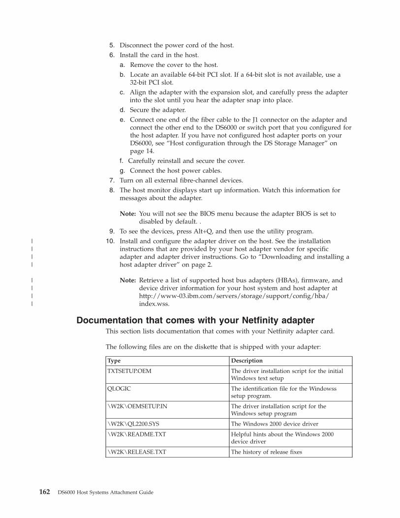
5. Disconnect the power cord of the host.
6. Install the card in the host.
a. Remove the cover to the host.
b. Locate an available 64-bit PCI slot. If a 64-bit slot is not available, use a
32-bit PCI slot.
c. Align the adapter with the expansion slot, and carefully press the adapter
into the slot until you hear the adapter snap into place.
d. Secure the adapter.
e. Connect one end of the fiber cable to the J1 connector on the adapter and
connect the other end to the DS6000 or switch port that you configured for
the host adapter. If you have not configured host adapter ports on your
DS6000, see “Host configuration through the DS Storage Manager” on
page 14.
f. Carefully reinstall and secure the cover.
g. Connect the host power cables. 7. Turn on all external fibre-channel devices.
8. The host monitor displays start up information. Watch this information for
messages about the adapter.
Note: You will not see the BIOS menu because the adapter BIOS is set to
disabled by default. .
9. To see the devices, press Alt+Q, and then use the utility program.
10. Install and configure the adapter driver on the host. See the installation
instructions that are provided by your host adapter vendor for specific
adapter and adapter driver instructions. Go to “Downloading and installing a
host adapter driver” on page 2.
Note: Retrieve a list of supported host bus adapters (HBAs), firmware, and
device driver information for your host system and host adapter at
http://www-03.ibm.com/servers/storage/support/config/hba/index.wss.
Documentation that comes with your Netfinity adapter
This section lists documentation that comes with your Netfinity adapter card.
The following files are on the diskette that is shipped with your adapter:
Type Description
TXTSETUP.OEM The driver installation script for the initial
Windows text setup
QLOGIC The identification file for the Windowss
setup program.
\W2K\OEMSETUP.IN The driver installation script for the
Windows setup program
\W2K\QL2200.SYS The Windows 2000 device driver
\W2K\README.TXT Helpful hints about the Windows 2000
device driver
\W2K\RELEASE.TXT The history of release fixes
162 DS6000 Host Systems Attachment Guide
||||
||||

Installing a QLogic adapter and driver for Windows 2000 or 2003
This section describes how install a QLogic adapter card on a Windows 2000 or
2003 host and provides the recommending settings for the adapter.
1. Install the QLogic adapter card in the host system.
2. Connect the cable to the storage unit port.
3. Install and configure the adapter driver. See the installation instructions that are
provided by your host adapter vendor for specific adapter and adapter driver
instructions. Go to “Downloading and installing a host adapter driver” on page
2 or to http://support.qlogic.com/support/oem_ibm.asp.
4. Restart the host.
5. Press Ctrl+Q to get to the FAST!Util menu.
6. Use FAST!Util to set the parameters to the values that are listed in Table 12.
Note: “Installing a QLogic adapter and driver for Windows 2000 or 2003”
contains settings for the QLogic QLA23xx, QLA246x, and QLE246x
adapters.
Table 12. Recommended settings for the QLogic QLA23xx, QLA246x, and QLE246x
adapters for Windows 2000 or 2003
Parameters Recommended settings
Basic Input/Output System (BIOS) Disabled
Frame size 2048
Loop reset delay 5 (minimum)
Adapter hard loop ID Disabled
Hard loop ID 0
Execution throttle 100
Fast command posting Enabled
>4 GB addressing Disabled (for 32-bit systems)
LUNs per target 0
Enable LIP reset No
Enable LIP full login Yes
Enable target reset Yes
Note: Enable LIP reset, Enable LIP full login, and
Enable target reset parameters control the behavior
of the adapter when Windows tries to do a SCSI bus
reset. You must perform a target reset operation to
make cluster failovers work. Use the SCSI bus
device reset option to clear SCSI reservations.
Login retry count 20 (minimum)
Port down retry count 20 (minimum)
Driver load RISC code Enabled
Enable database updates No
Disable database load No
IOCB allocation 256
Extended error logging Disabled (You might want to enable this parameter
if you use the debugging function.)
Chapter 15. Intel or AMD running Microsoft Windows 2000 or 2003 host attachment 163
||||
|||
|||
||
||
||
||
||
||
||
||
||
||
||
||
||||||||
||
||
||
||
||
||
|||

Table 12. Recommended settings for the QLogic QLA23xx, QLA246x, and QLE246x
adapters for Windows 2000 or 2003 (continued)
Parameters Recommended settings
Type of connection v Loop only
v Point-to-point
v Loop preferred (If you cannot use arbitrated loop,
then default to point-to-point.)
v Point-to point, otherwise loop only (If you cannot
use point-to-point, default to arbitrated loop.)
Notes:
1. If you connect the storage unit directly to the
host system, the option that you select must
match the port connections on the storage unit.
2. If you connect through a switch, the options do
not need to match the port connections because
the storage unit is point-to-point.
3. The appropriate host adapter on the server must
also support a point-to-point connection on a
direct connection.
4. If you use adapter cards from different
manufacturers, they will not function properly in
a direct point-to-point connection. This is not
true if you connect through a switch because the
storage unit is point-to-point.
7. Restart the server.
Updating the Windows 2000 or 2003 device driver
This section provides instructions to replace an existing Windows 2000 or 2003
device driver with an updated version.
1. Right click My Computer → Manage → Device Manager.
2. Click the plus (+) sign to expand the menu for SCSI and RAID Controllers.
3. Right click on the adapter that you want to update and select Properties.
4. Select the tab for Driver.
5. Click Update Driver and follow the instructions that appear on the screen.
Locating the WWPN for a Windows 2000 or 2003 host
Complete this task to locate the worldwide port name (WWPN) for a Windows
2000 or Windows 2003 with either the QLogic or the Emulex adapter.
1. Perform the following steps to locate the WWPN for a Windows 2000 or 2003
host system with a QLogic adapter:
a. Restart the server.
b. Press Alt+Q to get the FAST!Util menu.
Note: If you have more than one fibre-channel adapter installed, all the
fibre-channel adapters display. Scroll down to the adapter you want.
Press Enter.
c. From the FAST!Util menu, scroll down and select Select Host Adapter.
d. Scroll up and highlight Configuration Settings. Press Enter.
164 DS6000 Host Systems Attachment Guide
||
||
||
|
||
||
|
|||
|||
|||
||||||

e. From the Configuration Settings menu, click Host Adapter Settings.
f. Write down the 16-digit alphanumeric string that is displayed on your
screen.2. Perform the following steps to locate the WWPN for a Windows 2000 or 2003
host system with an Emulex adapter:
a. Click Start → Programs → Emulex Configuration Tool.
b. From the Emulex Configuration Tool menu in the Available Adapters
window, double-click the adapter entry for which you want to display the
WWPN information.
Verifying that Windows 2000 or 2003 is configured for storage
This section provides instructions to determine if your Windows 2000 or 2003 host
system is configured for storage.
1. Partition new drives with Disk Management.
2. From the Windows Server desktop, right click Start.
3. Click Explore and verify that you can see the fibre-channel drives.
4. Select a large file (for example, 9 MB file), and drag (copy) it to a fibre-channel
drive.
5. Verify the file copied to the selected drive.
Setting the TimeOutValue registry for Windows 2000 or 2003
This section describes how to ensure optimum availability and recoverability when
you attach a storage unit to a Windows 2000 or 2003 host system by setting the
Windows TimeOutValue registry.
You must set the TimeOutValue value associated with the supported host adapters
to 60 seconds. The setting is consistent with the configuration for FC-AL adapters
and disk subsystems when attached to Windows 2000 or 2003 host system.
The host adapter uses the TimeOutValue parameter to bind its recovery actions
and responses to the disk subsystem. The value exists in different places in the
system configuration. You can retrieve and use it in different ways depending on
the type of host adapter that is installed.
Follow these steps to modify the value in the Windows 2000 or 2003 registry.
1. From the Run menu or command prompt, type:
Regedt32.exe
2. Navigate to the following registry key:
HKEY_LOCAL_MACHINE\SYSTEM\CurrentControlSet\Services\Disk
3. Look for the value called TimeOutValue. If the value called TimeOutValue does
not exist, go to step 3a. If the TimeOutValue exists, go to step 4 on page 166.
a. Click Edit → Add Value...
b. For ValueName, type: TimeOutValue.
c. For data type, type: REG-DWORD.
d. Click OK.
e. For data, type: 3c.
f. For radix, click Hex.
g. Click OK.
Chapter 15. Intel or AMD running Microsoft Windows 2000 or 2003 host attachment 165

4. If the value exists and is less than 0x0000003c (60 decimal), perform the
following steps to increase it to 0x3c.
a. Click TimeOutValue.
b. Click Edit → DWORD....
c. For data, type: 3c.
d. For radix, click Hex.
e. Click OK.5. Exit the Regedt32 program.
6. Restart your Windows 2000 or 2003 server for the changes to take effect.
Installing remote fibre-channel boot support for a Windows 2000 or
2003 host system
This section provides instructions for installing remote fibre-channel boot support
for a Windows 2000 or 2003 host system.
You must obtain the following items before you can begin to install remote
fibre-channel boot support:
v The IBM System Storage Enterprise Storage Server Subsystem Device Driver User’s
Guide at http://www-03.ibm.com/servers/storage/support/software/sdd.
v The IBM System Storage DS6000 Introduction and Planning Guide.
v Either the Windows 2000/2003 CD-ROM or a set of Windows 2000/2003 setup
floppy disks with the Windows 2000/2003 CD-ROM.
v The Windows 2000 or 2003 installation instructions.
v The supported fibre-channel host adapter driver package.
v The supported fibre-channel host adapter driver documentation.
Ensure that the host adapters are installed and cable connections of the host,
switch, and storage unit are complete and functional.
Extract and copy the driver files to a floppy.
Remote fibre-channel boot support is available for Windows 2000 or 2003 with or
without SDD. For information on the SDD hardware and software installation
requirements, see IBM System Storage Multipath Subsystem Device Driver User’s
Guide.
Configure zoning and obtain storage
1. Reboot the host system to obtain the Host Bus Adapter WWPN:
a. For QLogic host adapters: A QLogic BIOS banner appears, press <Alt Q> or
press <Ctrl Q> as indicated, depending on the BIOS level. For each host
adapter, select Configuration Settings -> Host Bus Adapter Settings and
write down the host adapter WWPN.
b. For Emulex host adapters: When the BIOS banner appears, press either
<Alt E> or press <Alt F5> as indicated, depending on the BIOS level. A list
of adapters is displayed. For each host adapter, select the adapter and write
down the host adapter WWPN.2. Configure appropriate zoning on the switch to include only the storage unit
WWPN and one host adapter WWPN.
3. Use the IBM System Storage DS Storage Manager to add the host system to the
list of host systems that are available for attachment to the storage unit. For
166 DS6000 Host Systems Attachment Guide
||

detailed information of how to use the IBM System Storage DS Storage
Manager, refer to the IBM System Storage DS6000 Introduction and Planning
Guide.
4. Use the IBM System Storage DS Storage Manager to perform storage allocation
to the host system.
Flash QLogic host adapter
Because the host adapter BIOS is responsible for scanning the fibre-channel bus to
locate the remote boot device, check that the latest supported host adapter BIOS is
loaded. If not, follow the host adapter documentation to update the BIOS of the
host adapter.
Configure QLogic and Emulex host adapters
1. Return to the host system.
2. For QLogic host adapters: When the QLogic BIOS banner appears, press <Ctrl
Q>. The QLogic Fast!UTIL Menu appears. Depending on the host adapter BIOS
version, the BIOS menu may be different in the following step:
a. Select Configuration Settings->Host Bus Adapter Settings. Set only one of
the Host Adapters BIOS to Enabled and set Connection Options
appropriately. For example, set to 1 for fabric point-to-point. Press ESC to
return to the previous menu.
b. Select Configuration Settings->Selectable Boot Settings. Set Selectable Boot
to Enabled and select the appropriate Boot Port Name and the LUN that
corresponds to the WWPN of the storage unit.3. For Emulex host adapters: When Emulex BIOS banner appears, press Alt E or
press Alt F5 as indicated, depending on the BIOS level. A list of adapters is
displayed. For each host adapter, select the adapter by entering the appropriate
number.
a. Set only one host adapter to Enabled and set Topology appropriately. For
example, set to 1 for fabric point-to-point. Press ESC to return to the
previous menu.
b. Select Configure Boot Devices and configure one boot device, including the
boot device, the boot entry WWPN, and the starting LUN.4. Exit the BIOS utility and select to save changes.
Windows 2000 and 2003 installation
Apply the Windows Server installation instructions. These instructions include the
following steps:
1. Reboot the host system and insert the Windows setup CD-ROM in the
CD-ROM drive.
2. If prompted with the message, Press any key to boot from CD, press any key.
3. Respond to Press F6 if you want to install a third party SCSI or RAID driver
message by pressing F6
4. On Welcome to Setup panel, press Enter to select the Set up of Windows now
message.
5. Answer appropriately on the Windows Licensing Agreement panel.
6. Press ESC to reply to the Continue installing a fresh copy of Windows prompt.
7. When prompted, choose the disk on the storage unit where the Windows
Server operating system will reside.
Chapter 15. Intel or AMD running Microsoft Windows 2000 or 2003 host attachment 167

Windows 2000 and 2003 Post Installation
1. Once Windows Server installation is complete, install the IBM Subsystem
Device Driver (SDD). Refer to the IBM System Storage Multipath Subsystem
Device Driver User’s Guide and the SDD Readme.txt for the installation of SDD.
2. Update zoning on the switch to permit the availability of multiple paths.
168 DS6000 Host Systems Attachment Guide

Chapter 16. Intel running Novell NetWare host attachment
This chapter describes how you attach a Novell NetWare host system to a DS6000
with fibre-channel adapters.
This chapter contains the following host attachment topics:
v Downloading and installing an Emulex or QLogic adapter
– Installing the Emulex adapter for a Novell NetWare host
– Downloading the current Emulex adapter driver for a Novell NetWare host
– Installing the Emulex adapter driver for a Novell NetWare host
– Downloading the current QLogic adapter driver for a Novell NetWare host
– Installing the QLogic QLA23xx adapter for a Novell NetWare host
– Installing QLogic adapter drivers for a Novell NetWare hostv Locating the WWPN for a Novell NetWare host
Before you attach a host, review the following information:
v The “General requirements for attaching a host system” on page 1
v The DS6000 Interoperability Matrix at http://www.ibm.com/servers/storage/disk/ds6000/interop.html for the most current information and details for hosts,
operating systems, adapters, and switches
v A list of supported host bus adapters (HBAs), firmware, and device driver
information for your host system and host adapter at http://www-03.ibm.com/servers/storage/support/config/hba/index.wss
Installing an Emulex adapter and driver for a Novell NetWare host
This section provides installation steps for installing the Emulex adapter driver on
a Novell NetWare host.
If you are installing the fibre-channel adapter for the first time, you must specify
the correct topology. You must also select the appropriate device mapping driver.
Perform the following steps to install an Emulex adapter and driver:
1. Record the IEEE number that is printed on the adapter card. You can use the
IEEE number to determine the WWPN.
2. Install the Emulex adapter card in the host system.
3. Connect the cable to the adapter and to the DS6000 or switch port that you
configured for the host adapter. If you have not configured host adapter ports
on your DS6000, see “Host configuration through the DS Storage Manager” on
page 14.
4. Install and configure the adapter driver on the host. Refer to the installation
instructions provided by your host adapter vendor for specific adapter and
adapter driver instructions. Go to “Downloading and installing a host adapter
driver” on page 2 or http://www.emulex.com/ts/docoem/ibm/index.htm .
5. Once you have installed the driver from the NetWare server console, enter the
following command: nwconfig. This command applies to NetWare 5.0 or later.
6. Click NCF Files Options.
7. Select Edit STARTUP.NCF file.
© Copyright IBM Corp. 2004, 2006 169
|||

8. Insert the following statement at the beginning of the STARTUP.NCF file: SET
MULTI-PATH SUPPORT=OFF
9. Find the LOAD statement for the LPFC.HAM driver and ensure that it reads
as follows: LOAD LPFC.HAM SLOT=XXXX TOPOLOGY=1 /LUN MAX_LUN=32 RSCNZONE=1
10. Save the STARTUP.NCF file.
11. Restart the server, or unload and reload the LPFC driver manually.
Note: The MAX_LUN parameter must be set to a number greater than the LUNs
you have assigned to the adapter.
Installing a QLogic adapter and driver for a Novell NetWare host
This section tells you how you install a QLogic adapter and driver on a Novell
NetWare host system.
Single- and dual-port fibre-channel interfaces with the QLogic QLA23xx and
QLA246x adapters support the following public and private loop modes:
v Target
v Public initiator
v Private initiator
v Target and public initiator
v Target and private initiator
Perform the following steps to install a QLogic adapter and driver:
Note: The following steps are an example of a configuration using the QLogic
QLA23xx adapter. The configuration for your adapter might differ.
1. Install the QLogic adapter in the host system.
2. Connect the cable to the adapter and to the DS6000 or switch port that you
configured for the host adapter. If you have not configured host adapter ports
on your DS6000, see “Host configuration through the DS Storage Manager” on
page 14.
3. Restart the server.
4. Press Ctrl+Q to get to the FAST!Util menu.
5. Use FAST!Util to set the parameters to the values listed in Table 13:
Table 13. Recommended settings for the QLogic QLA23xx, and QLA246x adapters for a
Novell NetWare host
Parameters Recommended settings
Basic Input/Output System
(BIOS)
Disabled
Frame size 2048
Loop reset delay 5 (minimum)
Adapter hard loop ID Disabled
Hard loop ID 0
Execution throttle 16
Fast command posting Enabled
>4 GB addressing Disabled (for 32-bit systems)
170 DS6000 Host Systems Attachment Guide
|
|
||
||

Table 13. Recommended settings for the QLogic QLA23xx, and QLA246x adapters for a
Novell NetWare host (continued)
Parameters Recommended settings
LUNs per target 32
Note: Set LUNs per target to a number greater than
the LUNs you have assigned to the adapter.
Enable LIP reset No
Enable LIP full login Yes
Enable target reset Yes
Login retry count 20 (minimum)
Port down retry count 20 (minimum)
Driver load RISC code Enabled
Enable database updates No
Disable database load No
IOCB allocation 256
Extended error logging Disabled (You might want to enable this parameter if
you use debugging.)
Type of connection v Loop only
v Point-to-point
v Loop preferred (If you cannot use arbitrated loop,
then default to point-to-point.)
v Point-to point, otherwise loop (If you cannot use
point-to-point, default to arbitrated loop.)
Note: If you connect the storage unit directly to the
host system, the option you select must match the port
connections on the storage unit.
6. Install and configure the adapter driver on the host. See “Installing a QLogic
adapter driver for a Novell NetWare host” for instructions.
7. Restart the server.
Installing a QLogic adapter driver for a Novell NetWare host
This section provides instructions for installing a QLogic adapter driver for a
Novell NetWare host.
1. From the NetWare server console, type nwconfig for NetWare 5.0 or later.
2. Click Driver Options.
3. Click Configure Disk and Storage Device Drivers.
4. Click Select an additional driver.
5. Press the Insert key.
6. Insert a floppy diskette with the QLogic drivers into the A:\ drive of the
NetWare server. Press Enter.
The available driver is displayed.
Note: See “Downloading and installing a host adapter driver” on page 2 for
instructions on downloading a QLogic adapter driver.
7. Click the driver for the QLogic card, and press Enter.
8. Select Select/Modify driver parameters, and type the slot number of the
QLogic card into the slot number parameter.
Chapter 16. Intel running Novell NetWare host attachment 171

9. Set the Scan All LUNs parameter to Yes.
10. Press the Tab key and check the Save Parameters and Load Driver check box.
11. Press Esc twice to return to the Configuration Options menu.
a. Highlight the NCF Files Options menu and press Enter.
b. Select Edit the STARTUP.NCF and press Enter.
c. Verify the location of the STARTUP.NCF file, and modify it as necessary.
Press Enter.
d. Enter the following statement at the beginning of the STARTUP.NCF file:
SET MULTI-PATH SUPPORT=OFF
e. Find the LOAD statement for the QL2300.HAM driver and ensure that it
reads as follows:
LOAD QL2300.HAM slot=xxxx /luns /xretry=12 /xtimeout=120
Note: If you are using the IBM Multipath Subsystem Device Driver (SDD),
you must turn off QLogic failover at the adapter and portnames
level using the following command: LOAD QL2300.HAM slot=xxxx
/luns /xretry=12 /xtimeout=120 /allpaths /portnames.
f. Find the line that reads:
LOAD QLCSFTE
Modify the line to read: REM LOAD QLCSFTE
g. Press Esc and select Yes when prompted to save the file.12. Type UNLOAD QL2300.HAM.
13. Type LOAD QL2300.HAM slot=xxxx /luns /xretry=12 /xtimeout=120, where
xxxx is the PCI slot number where the QL23xx card is installed.
Note: If you are using the IBM Multipath Subsystem Device Driver (SDD),
you must turn off QLogic failover at the adapter and portnames level
using the following command: LOAD QL2300.HAM slot=xxxx /luns
/xretry=12 /xtimeout=120 /allpaths /portnames.
The storage unit volumes are displayed in the devices list. Create volumes using
the nssmu utility if necessary.
Locating the WWPN for a QLogic adapter on a Novell NetWare
host
Complete this task to locate the WWPN for a Novell NetWare host.
1. Restart the server.
2. Press Alt+Q to get the FAST!Util menu.
Note: If you have more than one fibre channel adapter installed, all the
adapters display on the screen. Scroll down to the adapter you want.
Press Enter.
3. From the FAST!Util menu, scroll down and select Select Host Adapter.
4. Scroll up and highlight Configuration Settings. Press Enter.
5. From the Configuration Settings menu, click Host Adapter Settings.
6. Write down the 16-digit alphanumeric string that is displayed on your screen.
172 DS6000 Host Systems Attachment Guide
||
|
||||
|

Chapter 17. Silicon Graphics host attachment
This chapter describes how you attach a Silicon Graphics (SGI) host system to a
DS6000 with fibre-channel adapters.
This chapter contains the following host attachment topics:
v Checking the version of the IRIX operating system for the SGI host system
v Installing a fibre-channel adapter card for the SGI host system
v Verifying the installation of a fibre-channel adapter card for SGI
v Configuring the fibre-channel adapter drivers for SGI
v Installing an optical cable for SGI in a switched-fabric topology
v Installing an optical cable for SGI in an arbitrated loop topology
v Confirming switch connectivity for SGI
v Displaying zoning information for the switch
v Confirming storage connectivity on a SGI host
– Confirming storage connectivity for SGI in a switched-fabric topology
– Confirming storage connectivity for SGI in a fibre-channel arbitrated loop
topologyv Configuring the storage unit for host failover using IRIX multipathing
– Confirming the availability of failover
– Making a connection through a switched-fabric topology
– Making a connection through an arbitrated-loop topology
– Switching I/O operations between the primary and secondary pathsv Configuring storage
– Configuring storage in a switched fabric topology
– Configuring storage in an arbitrated loop topologyv Locating the WWPN on a Silicon Graphics host system
Before you attach a host, review the following information:
v The “General requirements for attaching a host system” on page 1
v The DS6000 Interoperability Matrix at http://www.ibm.com/servers/storage/disk/ds6000/interop.html for the most current information and details for hosts,
operating systems, adapters, and switches
v A list of supported host bus adapters (HBAs), firmware, and device driver
information for your host system and host adapter at http://www-03.ibm.com/servers/storage/support/config/hba/index.wss
Notes:
1. Ensure that you have the IRIX64 6.5.14 version or later installed on your
host system.
2. The SGI host system does not support the SDD because IRIX manages
multipathing.
3. You can also connect a nonclustered SGI host system to the storage unit
using the switched fabric topology on optical fiber media, SGI
© Copyright IBM Corp. 2004, 2006 173
|||

fibre-channel host bus adapters, and the IBM 2109 switch. You can also
connect directly from an SGI host system to a storage unit with the
arbitrated loop topology.
Checking the version of the IRIX operating system
This section provides the command to check the IRIX operating system version.
To confirm that you have the correct version of the IRIX operating system installed
on your host system, type # uname -Rs.
Installing a fibre-channel adapter card for the SGI host system
This section lists the steps to install a fibre-channel adapter card for the SGI host
system.
1. Install the adapter card in the host system.
2. Connect the cable to the storage unit port.
3. Restart the server.
Note: The IRIX driver is part of the IRIX operating system. There are no
additional driver packages. SGI is responsible for support and
distribution of the adapter when you use it in an SGI host system.
Verifying the installation of a fibre-channel adapter card for
SGI
Complete this task to verify your installation of a fibre-channel adapter card for
SGI.
1. Type # ls -l /hw/scsi_ctlr to verify that the command created the links for
the controllers.
Figure 65 shows example results for the # ls -l /hw/scsi_ctlr command. In
this example, the PCI host bus adapters are installed in slots 6 and 8 and the
XIO host bus adapters are installed in slots 7 and 9.
2. Type scsiha -w /hw/scsi_ctlr/<N>/bus, where <N> is the number of the PCI
bus, to confirm the installation of the fibre-channel driver.
Configuring the fibre-channel adapter drivers for SGI
Use the commands listed in this section to configure fibre-channel adapter drivers
for SGI.
1. Type # cd /var/sysgen/master.d to navigate to the necessary directory.
2. Type # vi qlfc to open the file.
3. Edit and configure the adapter driver for switched-fabric or arbitrated loop
topology. Use Table 14 on page 175 as a guide to set the
qlfc_use_connection_mode parameters.
# ls -l /hw/scsi_ctlr
lrw------- 1 root sys 50 Mar 27 10:31 6 -> /hw/module/1/slot/io7/xtalk_pci/pci/1/scsi_ctlr/0
lrw------- 1 root sys 48 Mar 27 10:31 7 -> /hw/module/1/slot/io2/pci_xio/pci/0/scsi_ctlr/0
lrw------- 1 root sys 50 Mar 27 10:31 8 -> /hw/module/1/slot/io6/xtalk_pci/pci/1/scsi_ctlr/0
lrw------- 1 root sys 48 Mar 27 10:31 9 -> /hw/module/1/slot/io2/pci_xio/pci/1/scsi_ctlr/0
Figure 65. Example of PCI bus slots
174 DS6000 Host Systems Attachment Guide

Table 14. qlfc_use_connection_mode parameters
qlfc_use_connection_mode Topology
0 Arbitrated loop
1 Switched-fabric
2 Loop preferred (default)
3 Point-to-point preferred, then loop
Installing an optical cable for SGI in a switched-fabric topology
Use the commands in this section to install an optical cable for SGI in a
switched-fabric topology.
1. Connect the fibre-channel host adapters from the SGI host system to an IBM
2109 or a Brocade switch.
2. Connect the storage unit fibre-channel host adapters to the switch.
Installing an optical cable for SGI in an arbitrated loop topology
Use the commands in this section to install an optical cable for SGI in an arbitrated
loop topology.
1. Connect the fibre-channel host adapters from the SGI host system directly to
the fibre-channel host adapters for the storage unit.
2. Connect the storage unit fibre-channel host adapters to the switch.
Confirming switch connectivity for SGI
Use the following commands to confirm switch connectivity for SGI.
1. Log in to the IBM or Brocade switch as administrator.
2. At the console prompt, type switchshow.
3. Confirm that each QLogic host adapter and storage unit host adapter has
performed a fabric log in to the switch.
Figure 66 on page 176 shows example results for the switchshow command for an
SGI host. In this example, ports 9 and 11 are used for testing other devices.
Chapter 17. Silicon Graphics host attachment 175
||
||
||
||
||
|||

Displaying zoning information for the switch
This section describes the command needed to display zoning information for the
switch.
Use the cfgShow command to display the zoning information of the switch.
Figure 67 on page 177 shows a zoning example based on the unique worldwide
port names of the host adapters and the storage unit fibre-channel ports. This is
known as soft zoning. Each path to a storage unit LUN has a separate zone. For
information on locating the worldwide port name for an SGI host, see “Locating
the WWPN for an SGI host” on page 177.
snj2109s16h1:osl> switchshow
switchName: snj2109s16h1
switchType: 2.4
switchState: Online
switchRole: Principal
switchDomain: 1
switchId: fffc01
switchWwn: 10:00:00:60:69:12:30:25
switchBeacon: OFF
port 0: sw Online F-Port 21:00:00:e0:8b:04:d5:39
port 1: sw Online F-Port 21:00:00:e0:8b:04:ee:3a
port 2: sw Online F-Port 21:00:00:e0:8b:03:8f:e6
port 3: sw Online F-Port 21:00:00:e0:8b:04:13:3a
port 4: sw Online F-Port 21:00:00:e0:8b:05:c4:07
port 5: sw Online F-Port 21:00:00:e0:8b:05:0f:08
port 6: sw Online F-Port 21:00:00:e0:8b:05:d2:07
port 7: sw Online F-Port 21:00:00:e0:8b:05:08:08
port 8: sw Online F-Port 21:00:00:e0:8b:04:e9:39
port 9: sw Online L-Port 1 public
port 10: sw Online F-Port 21:00:00:e0:8b:03:97:e6
port 11: sw Online L-Port 1 public
port 12: sw Online F-Port 21:00:00:e0:8b:05:d5:07
port 13: sw Online F-Port 50:05:07:63:00:c3:91:74
port 14: sw Online F-Port 21:00:00:e0:8b:05:07:08
port 15: sw Online F-Port 50:05:07:63:00:c7:91:74
Figure 66. Example results for the switchshow command
176 DS6000 Host Systems Attachment Guide

Locating the WWPN for an SGI host
Complete this task to locate the WWPN for an SGI host adapter.
1. Restart the server.
2. Type the scsiha -w [bus_number | device] command.
For example, type scsiha -w 6 7 8 9. Figure 68 shows an example of what you
see.
Confirming storage connectivity on a SGI host
Use the procedures in this section to confirm SGI storage connectivity for both the
switched fabric and arbitrated loop topologies.
osvl2109c:admin> cfgShow
Defined configuration:
cfg: osvl_lab
dc_1; w2k_1; MS6000Cluster; MSHPCluster; Tivoli; compaqzone1;
compaqzone2; MS8500Cluster; AIX_ZONE; OSPL3Zone;
MSCompaqCluster; SGI_Path1; SGI_Path2; NW;
Netfyzone1; Netfyzone2; Netfyzone3; Netfyzone4
...
zone: SGI_Path1
SGI01; ospl3_b1a2
zone: SGI_Path2
SGI02; ospl3_b4a2
...
alias: SGI01 21:00:00:e0:8b:04:d5:39
alias: SGI02 21:00:00:e0:8b:04:ee:3a
alias: ospl3_b1a2
50:05:07:63:00:c3:91:74
alias: ospl3_b4a2
50:05:07:63:00:c7:91:74
...
Effective configuration:
cfg: osvl_lab
...
zone: SGI_Path1
21:00:00:e0:8b:04:d5:39
50:05:07:63:00:c3:91:74
zone: SGI_Path2
21:00:00:e0:8b:04:ee:3a
50:05:07:63:00:c7:91:74
...
Figure 67. Example results for the cfgShow command
# scsiha -w 6 7 8 9
6 Portname: 210000e08b05d207
7 Portname: 210000e08b04d539
8 Portname: 210000e08b050808
9 Portname: 210000e08b038fe6
#
Figure 68. Example of the scsiha — bus_number device | command
Chapter 17. Silicon Graphics host attachment 177

Confirming storage connectivity for SGI in a switched-fabric
topology
Confirming storage connectivity for SGI in a switched-fabric topology
This section contains an example of a switched fabric connection with the
fibre-channel adapter cards. The following conditions apply to this example:
v The PCI-FC-1P-OPT adapter cards are on PCI busses 6 and 8.
v There are four LUNs defined on the storage unit.
v There are two connections from the switch to two host adapters on the storage
unit.
v The switch is not zoned. Therefore, each LUN is available on each host adapter
from each host bus adapter. This means that there are four instances of each
LUN for each adapter card.1. Type scsiha -r {bus_number | device} at the root of the shell prompt.
bus_number is the numerical value for the bus and device is numerical value of
the device.
2. Type scsiha -p {bus_number | device}.
3. Use the ioconfig -d -f /hw command to assign logical controller numbers in
the hardware graph to each of the newly discovered physical devices.
4. Use the hinv -c disk command to confirm that all four instances of each of the
four LUNs exists.
5. Use the ls -l /hw/rdisk command to verify that you named the directory the
same name as the worldwide node name of the storage unit.
6. Use the ls -l /hw/rdisk command to verify that directories for each LUN exist
in the /hw/rdisk/<wwnn> directory, where <wwnn> is the worldwide node
name of the device.
7. Type cd /hw/rdisk/<wwnn>, where <wwnn> is the worldwide node name of the
device, to change to the /hw/rdisk/<wwnn> directory. You must execute the
next command from within this directory.
8. Use the ls -lR lun* command to verify that the command created the
character-special files in each LUN* directory. The asterisk (*) acts as a
universal wildcard for any characters that might appear after the initial “LUN”
characters.
Confirming storage connectivity for SGI in a fibre-channel
arbitrated loop topology
Confirming storage connectivity for SGI in a fibre-channel arbitrated loop topology
This section contains an example of an arbitrated loop connection with the
fibre-channel adapter cards. The following conditions apply to this example:
v The PCI-FC-1P-OPT adapter cards are on PCI busses 6 and 8.
v There are four LUNs defined on the storage unit.
v Each host adapter is connected to a host adapter in the storage unit.
v Each host adapter maintains two instances of each LUN.1. Type scsiha -r {bus_number | device} at the root of the shell prompt.
bus_number is the numerical value for the bus and device is the numerical
value for the device.
2. Type scsiha -p {bus_number | device}.
3. Use the ioconfig -d -f /hw command to assign logical controller numbers in
the hardware graph to each of the newly discovered physical devices.
178 DS6000 Host Systems Attachment Guide

4. Use the hinv -c disk command to confirm that two instances of each of the
four LUNs exist.
5. Use the ls -l /hw/disk command to verify that the command created the
appropriate block special files in hw/disk for each LUN.
Configuring the storage unit for host failover using IRIX multipathing
This section describes how to configure the storage unit for host failover using
IRIX multipathing.
IRIX multipathing does not perform dynamic load-balancing; it only provides path
failover. You can achieve static load-balancing if you distribute the primary paths
evenly across the controllers when you set up the failover groups in the
/etc/failover.conf file.
When a failover occurs to the alternate path, you must use the /sbin/scsifo -s xxxx
command to manually return to the primary path. Where xxxx is the pathname.
When you have a host system with multiple host bus adapters or multiple paths to
the storage, IRIX automatically chooses the first path it encounters in the hardware
tree as the path to the storage. To prevent this from occurring when you perform a
static load-balance, you must configure the failover.conf file to point the I/O
operations to the correct path. This ensures that you assign a failover path or a
backup path for all I/O operations.
Host failover using IRIX multipathing requires the use of the XLV volume manager
or in the case of IRIX clusters, the XVM volume manager.
Note: You can also XVM in non-cluster mode.
Confirming the availability of failover
Confirming the availability of failover.
1. Use the chkconfig command to determine if failover is enabled.
2. If failover is not enabled, turn it on and start the failover script or restart the
server. Figure 69 shows an example of what commands to type if failover is
disabled.
Making a connection through a switched-fabric topology
Making a connection through a switched-fabric topology
1. Edit the /etc/failover.conf file to add primary and secondary paths to the
storage unit LUNs. “Confirming storage connectivity for SGI in a
switched-fabric topology” on page 178 describes the paths of the
character-special files. These files begin with the worldwide node name of the
storage unit. Figure 70 on page 180 shows an example of an edited
/etc/failover.conf file.
#chkconfig | grep failover
failover off
#chkconfig failover on
#/etc/init.d/failover init
#Configuring Failover.
Figure 69. Example of commands to turn failover on
Chapter 17. Silicon Graphics host attachment 179
||

2. Use the IRIX /sbin/scsifo -d command to confirm the failover configuration.
Making a connection through an arbitrated-loop topology
Making a connection through an arbitrated-loop topology
1. Edit the /etc/failover.conf file to add primary and secondary paths to storage
unit LUNs. Figure 71 shows an example of an edited /etc/failover.conf file that
adds paths to the storage unit LUNs.
2. Use the IRIX /sbin/scsifo -d to confirm the proper failover configuration.
Switching I/O operations between the primary and secondary
paths
Switching I/O operations between the primary and secondary paths
Use the sbin/scsifo -s command to manually switch from the primary path to the
alternate path. With this command, you can also specify the path from where you
want to switch within a failover group. For example, you might want to perform
this action to switch back to the initial primary path after a path failure.
Configuring storage in a switched fabric or arbitrated loop topology
The following sections describe how to configure storage in either a switched
fabric or arbitrated loop topology.
Note: The /hw directory is used to build the hardware graph. The hardware graph
represents the collection of all significant hardware that is connected to a
system. Do not specify the /hw entries in commands that pertain to disk
devices. Use the traditional /dev/rdsk entries instead. The following
example shows a naming convention for the disk devices.
#/usr/bin/fx -x -d /dev/rdsk/5005076300c003b4/lun1vol/c6p30000
Configuring storage in a switched fabric topology
Configuring storage in a switched fabric topology
c6lun0 5005076300c09174/lun0/c6p30000 \
5005076300c09174/lun0/c8p70000
c6lun1 5005076300c09174/lun1/c8p70000 \
5005076300c09174/lun1/c6p30000
c6lun2 5005076300c09174/lun2/c6p30000 \
5005076300c09174/lun2/c8p70000
c6lun3 5005076300c09174/lun3/c8p70000 \
5005076300c09174/lun3/c6p30000
Figure 70. Example of an edited /etc/failover.conf file
GroupA sc3d0l11 sc4d0l11
GroupB sc3d0l17 sc4d0l17
Figure 71. Example of an edited /etc/failover.conf file for an arbitrated loop connection
180 DS6000 Host Systems Attachment Guide

Figure 72 and Figure 73 on page 182 shows the standard IRIX storage configuration
utilities that you can use to partition and format the storage unit LUNs and to
create and mount the file systems. The commands are in bold type.
Note: You must be a root user to use these commands.
#/usr/bin/fx -x -d /dev/rdsk/5005076300c003b4/lun1vol/c6p30000
fx version 6.5, Jul 7, 2000
...opening /dev/rdsk/5005076300c003b4/lun1vol/c3p1000
...drive selftest...OK
Scsi drive type == IBM 2105F20 1206
----- please choose one (? for help, .. to quit this menu)-----
[exi]t [d]ebug/ [l]abel/ [a]uto
[b]adblock/ [exe]rcise/ [r]epartition/
fx> repartition
----- partitions-----
part type blocks Megabytes (base+size)
7: xlv 4096 + 71798784 2 + 35058
8: volhdr 0 + 4096 0 + 2
10: volume 0 + 71802880 0 + 35060
capacity is 71802880 blocks
----- please choose one (? for help, .. to quit this menu)-----
[ro]otdrive [o]ptiondrive [e]xpert
[u]srrootdrive [re]size
fx/repartition> o
fx/repartition/optiondrive: type of data partition = (xfs) xfs
Warning: you will need to re-install all software and restore user data
from backups after changing the partition layout. Changing partitions
will cause all data on the drive to be lost. Be sure you have the drive
backed up if it contains any user data. Continue? yes
----- partitions-----
part type blocks Megabytes (base+size)
7: xfs 4096 + 71798784 2 + 35058
8: volhdr 0 + 4096 0 + 2
10: volume 0 + 71802880 0 + 35060
capacity is 71802880 blocks
----- please choose one (? for help, .. to quit this menu)-----
[ro]otdrive [o]ptiondrive [e]xpert
[u]srrootdrive [re]size
fx/repartition> ..
----- please choose one (? for help, .. to quit this menu)-----
[exi]t [d]ebug/ [l]abel/ [a]uto
[b]adblock/ [exe]rcise/ [r]epartition/
fx>exit
Figure 72. Example commands for the IRIX switched fabric storage configuration utility
Chapter 17. Silicon Graphics host attachment 181

Configuring storage in an arbitrated loop topology
This section provides information for configuring storage in an arbitrated loop
topology.
Figure 74 on page 183 and Figure 75 on page 184 shows the standard IRIX storage
configuration utilities that you can use to partition and format the storage unit
LUNs and to create and mount file systems. The commands are in bold type.
# xlv_make
xlv_make> vol Sharks0
Sharks0
xlv_make> data
Sharks0.data
xlv_make> plex
Sharks0.data.0
xlv_make> ve -force "/dev/dsk/5005076300c003b4/lun1s7/c6p3s0000"
xlv_make> quit
# ls -l /dev/xlv
total 0
brw------- 1 root sys 192, 10 Mar 12 16:06 Sharks0
# mkfs -t xfs /dev/xlv/Sharks0
meta-data=/dev/xlv/Sharks0 isize=256 agcount=8, agsize=27403 blks
data = bsize=4096 blocks=219218, imaxpct=25
= sunit=0 swidth=0 blks, unwritten=1
naming =version 1 bsize=4096
log =internal log bsize=4096 blocks=1168
realtime =none extsz=65536 blocks=0, rtextents=0
# mkdir /lv1_mount
# mount -t xfs /dev/xlv/Sharks0 /lv1_mount
# df -k
Filesystem Type kbytes use avail %use Mounted on
/dev/root xfs 1961580 1750112 211468 90 /
/dev/xlv/Sharks0 xfs 872200 144 872056 1 /lv1_mount
#
Figure 73. Example commands for the IRIX switched fabric storage configuration utility, part 2
182 DS6000 Host Systems Attachment Guide
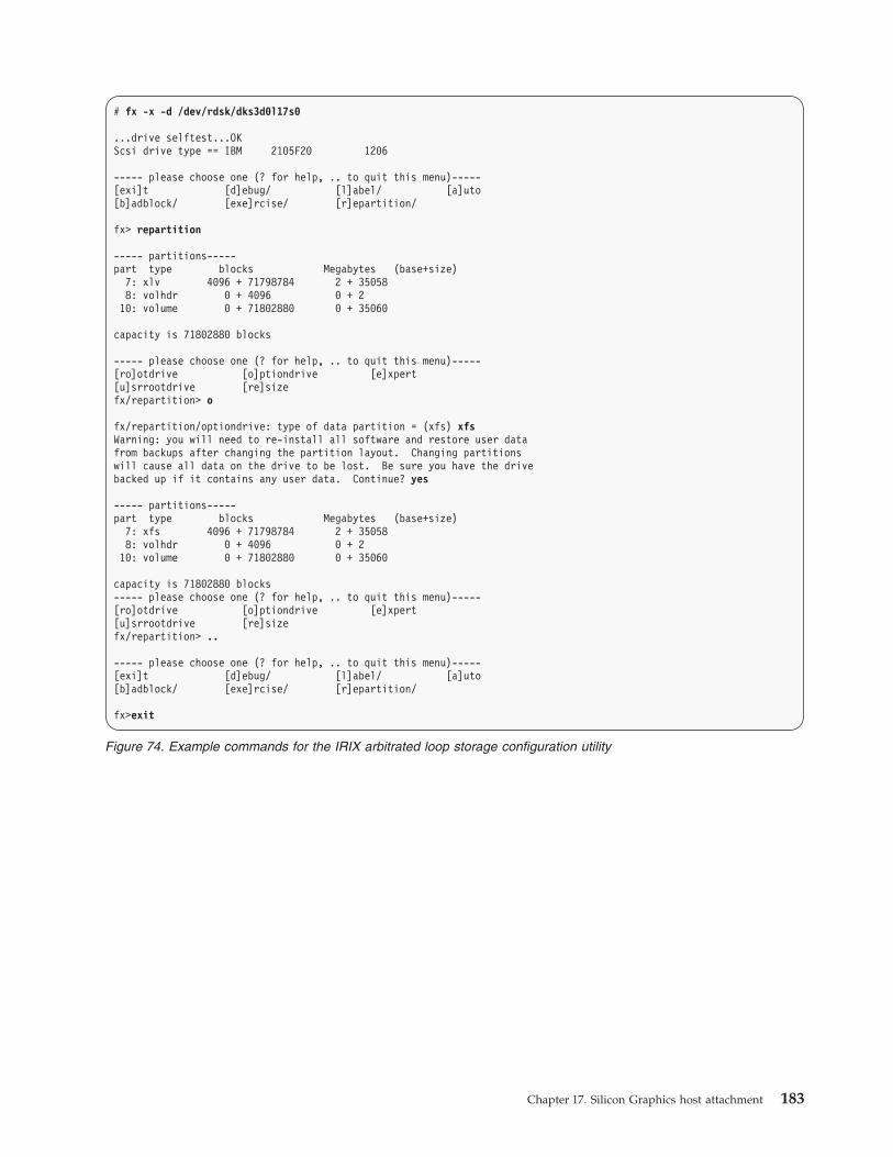
# fx -x -d /dev/rdsk/dks3d0l17s0
...drive selftest...OK
Scsi drive type == IBM 2105F20 1206
----- please choose one (? for help, .. to quit this menu)-----
[exi]t [d]ebug/ [l]abel/ [a]uto
[b]adblock/ [exe]rcise/ [r]epartition/
fx> repartition
----- partitions-----
part type blocks Megabytes (base+size)
7: xlv 4096 + 71798784 2 + 35058
8: volhdr 0 + 4096 0 + 2
10: volume 0 + 71802880 0 + 35060
capacity is 71802880 blocks
----- please choose one (? for help, .. to quit this menu)-----
[ro]otdrive [o]ptiondrive [e]xpert
[u]srrootdrive [re]size
fx/repartition> o
fx/repartition/optiondrive: type of data partition = (xfs) xfs
Warning: you will need to re-install all software and restore user data
from backups after changing the partition layout. Changing partitions
will cause all data on the drive to be lost. Be sure you have the drive
backed up if it contains any user data. Continue? yes
----- partitions-----
part type blocks Megabytes (base+size)
7: xfs 4096 + 71798784 2 + 35058
8: volhdr 0 + 4096 0 + 2
10: volume 0 + 71802880 0 + 35060
capacity is 71802880 blocks
----- please choose one (? for help, .. to quit this menu)-----
[ro]otdrive [o]ptiondrive [e]xpert
[u]srrootdrive [re]size
fx/repartition> ..
----- please choose one (? for help, .. to quit this menu)-----
[exi]t [d]ebug/ [l]abel/ [a]uto
[b]adblock/ [exe]rcise/ [r]epartition/
fx>exit
Figure 74. Example commands for the IRIX arbitrated loop storage configuration utility
Chapter 17. Silicon Graphics host attachment 183

# xlv_make
xlv_make> vol Sharks0
Sharks0
xlv_make> data
Sharks0.data
xlv_make> plex
Sharks0.data.0
xlv_make> ve -force "/dev/rdsk/dks3d0l17s0"
xlv_make> quit
# ls -l /dev/xlv
total 0
brw------- 1 root sys 192, 10 Mar 12 16:06 Sharks0
# mkfs -t xfs /dev/xlv/Sharks0
meta-data=/dev/xlv/Sharks0 isize=256 agcount=8, agsize=27403 blks
data = bsize=4096 blocks=219218, imaxpct=25
= sunit=0 swidth=0 blks, unwritten=1
naming =version 1 bsize=4096
log =internal log bsize=4096 blocks=1168
realtime =none extsz=65536 blocks=0, rtextents=0
# mkdir /lv1_mount
# mount -t xfs /dev/xlv/Sharks0 /lv1_mount
# df -k
Filesystem Type kbytes use avail %use Mounted on
/dev/root xfs 1961580 1750112 211468 90 /
/dev/xlv/Sharks0 xfs 872200 144 872056 1 /lv1_mount
#
Figure 75. Example commands for the IRIX arbitrated loop storage configuration utility, part 2
184 DS6000 Host Systems Attachment Guide

Chapter 18. Sun host attachment
This chapter describes how you attach a Sun host system to a DS6000 with
fibre-channel adapters.
This chapter contains the following host attachment sections:
v Installing fibre-channel adapters and adapter drivers for a Sun host
v Configuring host device drivers for Sun
v Setting the Sun host system parameters
v Locating the WWPN for a Sun host
v Attaching a storage unit to a Sun host using Storage Traffic Manager System
v Attaching a storage unit to a Sun host using Sun Cluster
Before you attach a host, review the following information:
v The “General requirements for attaching a host system” on page 1
v The DS6000 Interoperability Matrix at http://www.ibm.com/servers/storage/disk/ds6000/interop.html for the most current information and details for hosts,
operating systems, adapters, and switches
v A list of supported host bus adapters (HBAs), firmware, and device driver
information for your host system and host adapter at http://www-03.ibm.com/servers/storage/support/config/hba/index.wss
Note: Review device driver installation documents and configuration utility
documents for Solaris patches that you might need. For example, update
Solaris 8, 9 and 10 with required patches to ensure that the host and the
storage unit function correctly. Adapter drivers will not install properly if
you do not have the latest operating system patched installed.
The following table provides the minimum revision level that is required for each
system element.
Revision level System element
108528-03 kernel update
109524-02 ssd driver
109657-01 isp driver
108974-03 sd, uata drivers
Notes:
1. You can use the SDD for Sun host hardware platforms with 32- or 64-bit
mode capabilities that run Solaris 8, 9, or 10.
2. To have failover protection on an open system, SDD requires a
minimum of two fibre-channel adapters. The maximum number of
fibre-channel adapters supported is 16 for a total of 16 fibre-channel
ports.
3. SDD does not support the Sun host system in a clustering environment.
4. Use the procedures at http://www-03.ibm.com/servers/storage/support/software/sdd to install the Subsystem Device Driver (SDD).
© Copyright IBM Corp. 2004, 2006 185
|||
|||||

Installing an AMCC PCI adapter and driver on a Sun host
This section describes how to install an AMCC adapter and adapter driver on a
Sun host system running Solaris 8 or 9.
Note: AMCC adapters do not support Sun host systems running Solaris 10.
The following steps are general steps used to install AMCC adapters, before using
these steps to install the adapter and driver, read through all documentation that
comes with your adapter card and driver download and follow any specific
instructions included in that documentation.
1. Shutdown your host system.
2. Insert the AMCC PCI adapter into an available PCI slot.
3. Connect the cable to the adapter and to the DS6000 or switch port that you
configured for the host adapter. If you have not configured host adapter ports
on your DS6000, see “Host configuration through the DS Storage Manager” on
page 14.
4. Restart the system.
5. Use the instructions in “Downloading and installing a host adapter driver” on
page 2 to download and install the AMCC driver for your adapter.
Installing an Emulex adapter on a Sun host
This section describes how you install and Emulex adapter and configure the
adapter driver for a Sun host.
Note: The Emulex LP9402DC adapter card is a 3.3 volt card only and requires a
3.3 volt PCI slot.
Single- and dual-port, fibre-channel interfaces with an Emulex adapter card
support the following public and private loop modes:
v Target
v Public initiator
v Private initiator
v Target and public initiator
v Target and private initiator1. Record the IEEE number that is printed on the card. You can use the IEEE
number to determine the WWPN.
2. Shutdown your host system.
3. Insert the Emulex adapter into an available PCI slot.
4. Connect the cable to the adapter and to the DS6000 or switch port that you
configured for the host adapter. If you have not configured host adapter ports
on your DS6000, see “Host configuration through the DS Storage Manager” on
page 14.
5. Restart the system.
6. Use the instructions in “Downloading and installing a host adapter driver” on
page 2 to download and install the Emulex driver for your adapter.
Installing a Sun adapter and driver on a Sun host system
This section provides instructions for installing and configuring a Sun adapter and
adapter driver on a Sun host system running Solaris 8, 9, and 10.
186 DS6000 Host Systems Attachment Guide
|
||

The following steps are general steps to install Sun adapters. Before you perform
these steps to install the adapter and driver, read through all documentation that
comes with your adapter card and driver download, and follow any specific
instructions that are included in that documentation.
1. Shut down your host system.
2. Insert the Sun adapter into an available PCI slot.
3. Connect the cable to the adapter and to the DS6000 or to the switch port that
you have configured for the host adapter. If you have not configured host
adapter ports on your DS6000, see “Host configuration through the DS
Storage Manager” on page 14.
4. Restart the system.
5. Follow the instructions in “Downloading and installing a host adapter driver”
on page 2 to download the latest Sun driver for your adapter.
6. Log in to your Solaris system with root privileges.
7. Navigate to the directory where the compressed package file resides. Type
cd/<source directory>
where <source directory> is the directory where the compressed package file
resides after you have downloaded the driver from the Sun Web site.
8. Type the following command to uncompress the package file: tar xvf
SAN_4[1].4.7_install_it.tar
9. Navigate to the following directory: cd SAN_4.4.7_install_it
10. Type the following command to install the driver: ./install_it
11. Restart the system.
12. When the system has completed the restart, type the following command to
determine the connected fibre-channel adapters: cfgadm -al
13. To configure the adapters so that the Solaris operating system can recognize
the logical unit numbers (LUNs), type the following command: cfgadm -c
configure c3::500507630304c093
where <c3::500507630304c093> is the output from step 12, and is the WWPN
of the DS6000 adapter port that you connected in step 3.
14. Repeat step 13 as necessary to ensure that all LUNs are recognized.
15. Scan all attached devices using the following command: devfsadm
16. Type the format command to display all LUNs that were discovered by the
Solaris operating system.
Installing a QLogic adapter and driver on the Sun host
This section describes how you install a QLogic adapter and download and
configure the adapter driver for a Sun host.
1. Shutdown your host system.
2. Insert the QLogic adapter into a PCI or SBUS slot on your host.
3. Connect the cable to the adapter and to the DS6000 or switch port that you
configured for the host adapter. If you have not configured host adapter ports
on your DS6000, see “Host configuration through the DS Storage Manager” on
page 14.
4. Restart the system.
5. Use the instructions in “Downloading and installing a host adapter driver” on
page 2 to download the QLogic driver for your adapter.
6. Install the QLogic host adapter driver package:
a. Locate the package image file qlaxxxx.Z that you downloaded in step 5.
Chapter 18. Sun host attachment 187
||||
|
|
||||
|
||
|
||
||
||
|
|
|
||
|||
||
|
|
||
|

b. Log in to your Solaris system as root.
c. Type cd/tmp to change the directory to a temporary directory.
d. Type the following command to copy the compressed package file to the
/tmp directory:cp <source directory>/qlaxxxx.Z,
where <source directory> is the directory where the compressed package
file resides after downloading the driver.
e. Type the following command to uncompress the package file: uncompress
qlaxxxx.Z
Note: You must use an upper case Z when you specify the file name.
f. Transfer the QLogic driver package to a diskette before you use the package
to install the adapter drivers. Use the following procedure to create a
diskette that contains the QLogic driver package:
1) Type /etc/init.d/volmgt stop to stop the volume manager.
2) Type dd if=qlaxxxx of=/dev/rdiskette0 to transfer the image file.
Installing the QLogic adapter driver package for Sun
This section provides instructions to install the QLogic host adapter driver
package.
1. Obtain a copy of the package image file, qlaxxxx.Z by performing the steps in
“Downloading and installing a host adapter driver” on page 2.
2. Log in to your Solaris system as root.
3. Type cd/tmp to change the directory to a temporary directory.
4. Type the following command to copy the compressed package file to the /tmp
directory:cp <source directory>/qlaxxxx.Z
where <source directory> is the directory where the compressed package file
resides after downloading the driver from the QLogic Web site.
5. Type the following command to uncompress the package file:uncompress
qlaxxxx.Z
Note: You must use an upper case Z when you specify the file name.
6. Transfer the QLogic driver package to a diskette before you use the package to
install the adapter drivers. Use the following procedure to create a diskette that
contains the QLogic driver package:
a. Type /etc/init.d/volmgt stop to stop the volume manager.
b. Type dd if=qlaxxxx of=/dev/rdiskette0 to transfer the image file.
Configuring host device drivers for Sun
The following instructions explain how to update the device driver configuration
file on the Sun host to enable access to target and LUN pairs that are configured
on a DS6000.
Perform the following steps to update the Solaris driver configuration file:
Notes:
1. Do not change or remove entries in kernel /drv/sd.conf for preexisting
devices. Doing so can cause your system to become inoperable.
2. Do not add duplicate target and LUN pairs.1. Change directories by typing: cd /kernel/drv
188 DS6000 Host Systems Attachment Guide
||
||
||
|
|

2. Backup the sd.conf file in this subdirectory.
3. Edit the sd.conf file to add support for the target and LUN pairs that are
configured on the host system.
Figure 76 shows the lines that you must add to the file to access LUNs 0 - 49
on target 0 for fibre-channel.
Figure 77 shows the start lpfc auto-generated configuration.
Note: You will delete anything that you put within this auto-generated section
if you issue the pkgrm command to remove the lpfc driver package. You
might want to add additional lines to probe for additional LUNs or
targets. Delete any lines that represent lpfc targets or LUNs that are not
used.
4. From the Sun UNIX prompt, type:
name="sd" class="scsi"
target=0 lun=0;
name="sd" class="scsi"
target=0 lun=1;
name="sd" class="scsi"
target=0 lun=2;
name="sd" class="scsi"
target=0 lun=3;
name="sd" class="scsi"
target=0 lun=4;
name="sd" class="scsi"
target=0 lun=5;
name="sd" class="scsi"
target=0 lun=6;
name="sd" class="scsi"
target=0 lun=7;
name="sd" class="scsi"
.
.
.
name="sd" class="scsi"
target=0 lun=48;
name="sd" class="scsi"
target=0 lun=49;
Figure 76. Example of sd.conf file entries for fibre-channel
name="sd" parent="lpfc" target=0 lun=0;
name="sd" parent="lpfc" target=1 lun=0;
name="sd" parent="lpfc" target=2 lun=0;
name="sd" parent="lpfc" target=3 lun=0;
name="sd" parent="lpfc" target=4 lun=0;
name="sd" parent="lpfc" target=5 lun=0;
name="sd" parent="lpfc" target=6 lun=0;
name="sd" parent="lpfc" target=7 lun=0;
name="sd" parent="lpfc" target=8 lun=0;
name="sd" parent="lpfc" target=9 lun=0;
name="sd" parent="lpfc" target=10 lun=0;
name="sd" parent="lpfc" target=11 lun=0;
name="sd" parent="lpfc" target=12 lun=0;
name="sd" parent="lpfc" target=13 lun=0;
name="sd" parent="lpfc" target=14 lun=0;
name="sd" parent="lpfc" target=15 lun=0;
name="sd" parent="lpfc" target=16 lun=0;
name="sd" parent="lpfc" target=17 lun=0;
name="sd" parent="lpfc" target=17 lun=1;
name="sd" parent="lpfc" target=17 lun=2;
name="sd" parent="lpfc" target=17 lun=3;
Figure 77. Example of a start lpfc auto-generated configuration
Chapter 18. Sun host attachment 189
|

a. cd /
b. touch reconfigure
c. reboot
The fibre-channel adapters that are supported for attaching the storage unit to a
Sun host are capable of full-fabric support. Ensure that all fibre-channel driver
configurations include worldwide port name, worldwide node name, port ID,
or host adapter binding of target LUN pairs.
Binding of target LUN pairs implements the Solaris fibre-channel host adapter
configuration file that is installed by the adapter software package. Refer to the
manufacturer’s adapter documentation and utilities for detailed configuration
instructions.
You can tune fibre-channel host adapter configuration files for host system
reliability and performance.
Parameter settings for the AMCC adapters for the Sun host
system
You can use these recommended settings for your AMCC adapters on a Sun host
system.
Table 15 provides configuration settings that are recommended for the supported
adapters.
Table 15. Recommended configuration file parameters for a AMCC FCX-6562, AMCC
FCX2-6562, AMCC FCE-6460, or a AMCC FCE-1473 adapter
Parameters Recommended settings
FcEngHeartbeatInterval 5: Default.
When the AMCC adapter or driver detects that the
fibre-channel link is up (and there is no I/O activity), it
sends a test frame (or heartbeat) to itself to verify link
integrity. The test frame is sent at the interval specified by
this parameter. If the test frame does not complete, there
might be a link problem. In this situation, the driver
initiates error recovery to reestablish a good link. A value of
0 disables the heartbeat.
FcLinkUpRecoveryTime 1000: Default.
Delay (msec) after the link is up before port discovery
begins, allowing the link to stabilize and protecting against
a possible I/O surge. This timer is reset every time the link
comes up. The default value is adequate for most
configurations.
BusyRetryDelay 5000: Default.
Delay (msec) before retrying after receipt of an I/O
operation with a SCSI Busy status from a target. The
number of retries is based on the Solaris retry count
associated with the I/O operation.
FailoverDelay 30:
Delay (seconds) before failing all I/O operations for an
offline target. If the delay timer expires, all I/O operations
for the failed target is returned to the application. A zero
value disables failover.
190 DS6000 Host Systems Attachment Guide
|
|
|
||||
||||
||

Table 15. Recommended configuration file parameters for a AMCC FCX-6562, AMCC
FCX2-6562, AMCC FCE-6460, or a AMCC FCE-1473 adapter (continued)
Parameters Recommended settings
TimeoutResetEnable 0: False.
Boolean parameter for enabling SCSI target resets for
timed-out I/O operations. When the timer expires (usually
60 seconds, as specified by the upper layers), the driver
issues a target reset to attempt to clear the device (which
might be either too busy to respond or stuck).
QfullRetryCount 5: Default.
Number of times an I/O operation is retried due to receipt
of a SCSI queue full status from a target. The delay between
retries is based on the QfullRetryDelay parameter.
QfullRetryDelay 5000: Default.
Delay (msec) before retrying after receipt of an I/O
operation with a SCSI queue full status from a target. The
number of retries is based on the QfullRetryCount
parameter.
LunRecoveryInterval 50: Default.
Sets the LUN I/O recovery interval (in msec) after the
driver reconnects to a disk. It is a global parameter affecting
all targets, and determines how long the driver waits after a
port is discovered until sending I/O operations to that port.
Some devices might require more time to flush an I/O
operation that was in progress prior to a link going down; if
this is the case, increase the value of this parameter.
FcLinkSpeed 3: Default.
Specifies the desired fibre-channel link speed as follows:
v 0: default to SEEPROM setting
v 1: force 1 gigabit per second
v 2: force 2 gigabit per second
v 3: auto negotiate link speed
JniCreationDelay 5: Default.
Delay (seconds) after driver creation to allow the network to
stabilize, discover ports, and build the driver database.
Increase this value if targets are being discovered too late in
the restart process.
FlogiRetryCount 3: Default.
Total number of fabric login (FLOGI) attempts before giving
up logging in to a switch. Failure prevents participation on
a fabric topology.
FcFlogiTimeout 10: Default.
Specifies the amount of time (in seconds) that the driver
waits for a fabric login (FLOGI) to be accepted. The value
should be increased only if the switch to which the host
adapter is connected requires more time to respond to a
FLOGI. The number of retries is configured with the
FlogiRetryCount parameter.
Chapter 18. Sun host attachment 191

Table 15. Recommended configuration file parameters for a AMCC FCX-6562, AMCC
FCX2-6562, AMCC FCE-6460, or a AMCC FCE-1473 adapter (continued)
Parameters Recommended settings
PlogiRetryCount 5: Default.
Total number of port login (PLOGI) attempts before failing
to log in to a SCSI target.
PlogiControlSeconds 30: Default.
Defines the number of seconds that the driver waits for a
successful port login (PLOGI) attempt. The maximum
number of attempts is defined by the PlogiRetryCount
parameter. Some devices might take longer to respond to
PLOGIs; if this is the case, increase the value of this
parameter.
FcEmldEngTcbCount 1789: Default.
Total number of concurrent exchanges (also called transfer
control blocks) that the adapter allows. To optimize
performance, set this parameter to match the memory
capacity of the hardware.
TargetOfflineEnable Recommended setting: 0.
Function: Flag for enabling target offline when target port
fails.
1: Default. (Enable).
Setting the parameters for AMCC adapters on a SUN host
system
This section provides instructions for setting the system parameters for AMCC
adapters on a SUN host.
1. Type cd/etc to change to the /etc subdirectory.
2. Backup the system file in the subdirectory.
3. Edit the system file and set the following parameters for servers with
configurations that use AMCC adapters:
Note: To configure the AMCC adapters see the EZ Fibre Configuration Utility
at: http://www.amcc.com.
sd_max_throttle
This sd_max_throttle parameter specifies the maximum number of
commands that the sd driver can queue to the host adapter driver. The
default value is 256, but you must set the parameter to a value less
than or equal to a maximum queue depth for each LUN connected.
Determine the value by using the following formula: 256 ÷ (LUNs per
adapter) where LUNs per adapter is the largest number of LUNs
assigned to a single adapter.
To set the sd_max_throttle parameter for the storage unit LUNs in this
example, you would add the following line to the /etc/system file: set
sd:sd_max_throttle=5
sd_io_time
This parameter specifies the timeout value for disk operations. Add the
192 DS6000 Host Systems Attachment Guide
||

following line to the /etc/system file to set the sd_io_time parameter
for the storage unit LUNs:set sd:sd_io_time=0x78
sd_retry_count
This parameter specifies the retry count for disk operations. Add the
following line to the /etc/system file to set the sd_retry_count
parameter for the storage unit LUNs: set sd:sd_retry_count=5
maxphys
This parameter specifies the maximum number of bytes that you can
transfer for each SCSI transaction. The default value is 126976 (124 KB).
If the I/O block size that you requested exceeds the default value, the
request is broken into more than one request. You should tune the
value for the application requirements. For maximum bandwidth, set
the maxphys parameter by adding the following line to the
/etc/system file: set maxphys=1048576 (1 MB)
Note: Do not set the value for maxphys greater than 1048576 (1 MB). Doing so
can cause the system to hang.
Parameter settings for the Emulex adapters for the Sun host
system
You can use these recommended configuration settings for your Emulex adapters
on a Sun host system.
Table 16 provides configuration settings that are recommended for the Emulex
adapters.
Table 16. Recommended configuration file parameters for the Emulex LP9002DC, LP9002L,
LP9002S, LP9402DC, LP9802, LP10000, LP10000, 11000, and 11002 DC adapters
Parameters Recommended settings
automap 1: Default. SCSI IDs for all FCP nodes without persistent bindings are
automatically generated. If new FCP devices are added to the network
when the system is down, there is no guarantee that these SCSI IDs will
remain the same when the system is restarted. If one of the FCP binding
methods is specified, then automap devices use the same mapping
method to preserve SCSI IDs between link down and link up. If no
bindings are specified, a value of 1 forces WWNN binding, a value of 2
forces WWPN binding, and a value of 3 forces DID binding. If automap
is 0, only devices with persistent bindings are recognized by the system.
fcp-on 1: Default. Turn on FCP.
lun-queue-depth
30: The default value that the driver uses to limit the number of
outstanding commands per FCP LUN. This value is global, affecting each
LUN recognized by the driver, but can be overridden on a per-LUN
basis. You might have to configure RAID using the per-LUN tunable
throttles.
no-device-delay 0: Default. Implies no delay whatsoever.
1: Recommended.
2: Setting a long delay value might permit I/O operations to build up,
each with a pending timeout, which could result in the exhaustion of
critical Solaris kernel resources. In this case, you might see a fatal
message such as, PANIC: Timeout table overflow.
Chapter 18. Sun host attachment 193

Table 16. Recommended configuration file parameters for the Emulex LP9002DC, LP9002L,
LP9002S, LP9402DC, LP9802, LP10000, LP10000, 11000, and 11002 DC
adapters (continued)
Parameters Recommended settings
network-on 0: Default. Recommended for fabric. Do not turn on IP networking.
1: Turn on IP networking.
scan-down 0: Recommended. Causes the driver to use an inverted ALPA map,
effectively scanning ALPAs from high to low as specified in the FC-AL
annex.
2: Arbitrated loop topology.
tgt-queue-depth 0: Recommended. The default value that the driver uses to limit the
number of outstanding commands per FCP target. This value is global,
affecting each target recognized by the driver, but can be overridden on a
per-target basis. You might have to configure RAID using the per-target
tunable throttles.
topology 2: Recommended for fabric. Point-to-point topology only.
4: Recommended for nonfabric. Arbitrated-loop topology only.
xmt-que-size 256: Default. Size of the transmit queue for mbufs (128 - 10240).
zone-rscn 0: Default.
1: Recommended for fabric. Check the name server for RSCNs.
Setting zone-rscn to 1 causes the driver to check with the name server to
see if an N_Port ID received from an RSCN applies. If soft zoning is used
with Brocade fabrics, this parameter should be set to 1.
Setting the parameters for Emulex or QLogic adapters on a
SUN host system
This section provides instructions for setting the parameters for Emulex or QLogic
adapters on a SUN host system.
1. Type cd /etc to change to the /etc subdirectory.
2. Backup the system file in the subdirectory.
3. Edit the system file and set the following parameters for servers with
configurations that only use Emulex or QLogic adapters.
sd_max_throttle
This sd_max_throttle parameter specifies the maximum number of
commands that the sd driver can queue to the host adapter driver. The
default value is 256, but you must set the parameter to a value less
than or equal to a maximum queue depth for each connected LUN.
Determine the value by using the following formula: 256 ÷ (LUNs per
adapter) where LUNs per adapter is the largest number of LUNs that
are assigned to a single adapter.
To set the sd_max_throttle parameter for the storage unit LUNs in this
example, add the following line to the /etc/system file: set
sd:sd_max_throttle=5
sd_io_time
This parameter specifies the timeout value for disk operations. Add the
following line to the /etc/system file to set the sd_io_time parameter
for the storage unit LUNs: set sd:sd_io_time=0x78
194 DS6000 Host Systems Attachment Guide

sd_retry_count
This parameter specifies the retry count for disk operations. Add the
following line to the /etc/system file to set the sd_retry_count
parameter for the storage unit LUNs: set sd:sd_retry_count=5
maxphys
This parameter specifies the maximum number of bytes you can
transfer for each SCSI transaction. The default value is 12 6976 (124
KB). If the I/O block size that you requested exceeds the default value,
the request is broken into more than one request. You should tune the
value to the application requirements. For maximum bandwidth, set the
maxphys parameter by adding the following line to the /etc/system
file: set maxphys=1048576 (1 MB)
Note: Do not set the value for maxphys greater than 1048576 (1 MB).
Doing so can cause the system to hang.
Parameter settings for the QLogic QLA23xxF adapters for a
Sun host
You can use these recommended configuration settings for your QLogic adapters
on a Sun host system.
Table 17 provides configuration settings that are recommended for the QLogic
QLA2310F, QLA2340, and QLA2342 adapters. These settings are for a host that is
attached directly to DS6000 or through a fabric switch.
Table 17. Recommended configuration file parameters for the QLogic QLA2310F, QLA2340,
and QLA2342 adapters with driver level 4.03
Parameters Recommended settings
hba0-max-frame-length =2048;
hba0-max-iocb-allocation =256;
hba0-execution-throttle =31;
hba0-login-timeout =4;
hba0-login-retry-count =1;
hba0-fabric-retry-count =10;
hba0-adapter-hard-loop-ID =0;
hba0-enable or disable-64bit PCI DMA addressing v =0: disabled
v =1: enabled
hba0-enable or /disable-LIP-reset =0: disabled
hba0-enable or disable-LIP-full-login =1: enabled
hba0-enable or disable-target-reset =0: disabled
hba0-reset-delay =5;
hba0-port-down-retry-count =30;
hba0-link-down-error =1: enabled
hba0-loop-down-timeout =60;
hba0-connection-options v =0: loop only (for direct
attachment)
v =1: point-to-point only (for fabric
attachment)
Chapter 18. Sun host attachment 195

Table 17. Recommended configuration file parameters for the QLogic QLA2310F, QLA2340,
and QLA2342 adapters with driver level 4.03 (continued)
Parameters Recommended settings
hba0-device-configuration-mode =1: use port name
hba0-fc-tape v =0: disabled
v =1: enabled
hba0-fc-data-rate =2: Auto-negotiate
hba0-command-completion-option =0: response queue
persistent binding only option =0: reports the discovery of
persistent binded and non-binded
devices to the operating system
Parameter settings for the QLogic QLA23xx and QLA246x
adapters for San Surf configuration (4.06+ driver)
The following table provides the parameter settings for the QLogic QLA23xx and
QLogic QLA226x adapters for storage units with the San Surf configuration (4.06+
driver).
Table 18. Parameter settings for the QLogic QLA23xx and QLogic QLA246x host adapters
for San Surf Configuration (4.06+)
Adapter parameter Recommended settings
Host Parameters
Execution Throttle 16 (default)
Frame Length 2048
Port Down Retry Count 30
Connection Options v Loop Only
v Loop Retreived
v Point-to-Point
Enable Fibre Channel Tape Support Enable
Enable Fibre Channel Confirm Enable
Data Rate 2 Auto Negotiate
Advanced Host Parameters (See Note 1)
Persistent Plus New Enable
Persistent Target Only Disable
Persistent Bind HBA Disable
Fast Error Reporting Disable
Link Down Error Enable
Extended Logging Disable
Enable Target Reset Enable
Enable Fast Command Posting Disable
Enable 4Gb Addressing Disable
Maximum LUNs per Target 8 (default)
Loop Down Timeout 60 (default)
Advanced Firmware Parameters (See Note 1)
196 DS6000 Host Systems Attachment Guide

Table 18. Parameter settings for the QLogic QLA23xx and QLogic QLA246x host adapters
for San Surf Configuration (4.06+) (continued)
Adapter parameter Recommended settings
Enable Adapter Hard Loop ID Disable
Enable LIP Full Login Enable
Enable Class 2 Service Disable
Enable ACKO Disable
Enable Read Transfer Ready Disable
Hard Loop ID <default>
Login Retry Count 8
Interrupt Delay Timer 0
Wizard (for binding) (See Note 2)
Notes:
1. All of the parameters in the Advanced Host Parameters and Advanced Firmware
Parameters categories use the default parameter settings.
2. San Surf uses Wizard to update the binding configuration information in the
qlaxxxx.conf file. See Figure 78 for an example of the binding inserts.
Figure 78 shows an example qlaxxxx.conf file that contains binding inserts at the
end of the file.
Locating the WWPN for a Sun host
Complete this task to locate the WWPN for a Sun host adapter.
Note: If you have multiple host adapters installed, you will see more than one
WWPN.
Perform the following steps to locate the worldwide port name (WWPN) for the
following adapters:
hba3-SCSI-target-id-0-fibre-channel-node-name="5005076300c0863a";
hba3-SCSI-target-id-0-fibre-channel-port-name="5005076300cf863a";
hba3-SCSI-target-id-1-fibre-channel-node-name="5005076300c0863a";
hba3-SCSI-target-id-1-fibre-channel-port-name="5005076300cb863a";
hba2-SCSI-target-id-0-fibre-channel-node-name="5005076300c0863a";
hba2-SCSI-target-id-0-fibre-channel-port-name="5005076300cf863a";
hba2-SCSI-target-id-1-fibre-channel-node-name="5005076300c0863a";
hba2-SCSI-target-id-1-fibre-channel-port-name="5005076300cb863a";
hba1-SCSI-target-id-0-fibre-channel-node-name="5005076300c0863a";
hba1-SCSI-target-id-0-fibre-channel-port-name="5005076300c1863a";
hba1-SCSI-target-id-1-fibre-channel-node-name="5005076300c0863a";
hba1-SCSI-target-id-1-fibre-channel-port-name="5005076300c5863a";
hba0-SCSI-target-id-0-fibre-channel-node-name="5005076300c0863a";
hba0-SCSI-target-id-0-fibre-channel-port-name="5005076300c5863a";
hba0-SCSI-target-id-1-fibre-channel-node-name="5005076300c0863a";
hba0-SCSI-target-id-1-fibre-channel-port-name="5005076300c1863a";
Figure 78. Example binding inserts for qlaxxxx.conf
Chapter 18. Sun host attachment 197

v AMCC PCI adapter
v AMCC SBUS adapter
v QLogic adapter
v Emulex adapter1. After you install the adapter and you restart the host system, view the
/var/adm/messages file.
2. Search for the line that contains the following phrase:
a. For the AMCC SBUS adapter, search for fcawx: Fibre Channel WWNN, where
x is the adapter number (0, 1, and so on). You can find the WWPN on the
same line immediately after the WWNN.
b. For the AMCC PCI adapter, search for fca-pcix: Fibre Channel WWNN,
where x is the adapter number (0, 1, and so on). You can find the WWPN
on the same line following the WWNN.
c. For the 2Gb AMCC adapter, search for AMCCc146xN: Fibre Channel WWNN,
where N is the adapter number (0, 1, and so on). You can find the WWPN
on the same line following the WWNN.
d. For the QLogic QLA23xx adapter, search for qla23200-hbax-adapter-port-name where x is the adapter number (0, 1, and so on).
e. For the Emulex adapter, search for lpfcx: Fibre Channel WWNN, where x is
the adapter number 0, 1, and so on).
Attaching a Sun host using Storage Traffic Manager System to a
DS6000
This section provides instructions for attaching a a Sun host using Storage Traffic
Manager System to a DS6000.
The Storage Traffic Manager System (STMS) is a multipathing mechanism for
native Sun systems. Using the DS CLI, you can specify Sun - Solaris as port
profile. Using the Storage Manager GUI, you can specify Sun servers (Solaris)
(Sun) as host system when attaching the storage unit to a host operating with
STMS.
See the Sun Web site at http://www.sun.com for up-to-date documentation.
Notes:
Use the following Sun documentation for the required configuration
changes to enable Sun MPxIO multipathing software with a DS6000.
1. For Solaris 8 and 9 refer to Sun StorEdge Traffic Manager Installation and
Configuration Guide For the Solaris OS & Sun SAN Foundation Software 4.4
at http://docs.sun.com/app/docs/doc/817-3674-12?q=817-3674.
2. For Solaris 10 refer to Solaris Fibre Channel Storage Configuration and
Multipathing Support Guide at http://docs.sun.com/app/docs/doc/819-0139?q=819-0139.
Configuring the Sun STMS host settings
This section provides instructions for configuring the Sun STMS host settings.
1. Type cd /etc to change to the /etc subdirectory.
2. Backup the system file in the subdirectory.
198 DS6000 Host Systems Attachment Guide

3. Edit the system file and set the following parameters for servers with
configurations that only use Sun Branded adapters:
ssd_io_time
This parameter specifies the timeout value for disk operations. Add the
following line to the /etc/system file to set the ssd_io_time parameter
for the storage unit LUNs:
set ssd:ssd_io_time=0x78
ssd_max_throttle
This ssd_max_throttle parameter specifies the maximum number of
commands that the SSD driver can queue to the host adapter driver.
The default value is 256, but you must set the parameter to a value less
than or equal to a maximum queue depth for each connected LUN.
Determine the value by using the following formula:
256 ÷ (LUNs per adapter)
where LUNs per adapter is the largest number of LUNs assigned to a
single adapter.
To set the ssd_max_throttle parameter for the storage unit LUNs in this
example, add the following line to the /etc/system file:
set ssd:ssd_max_throttle=5
Attaching a Sun host using Sun Cluster
This section provides instructions for attaching a storage unit to a Sun host using
Sun Cluster.
See the Sun Web site at http://www.sun.com for up-to-date documentation.
Attention:
Due to a problem found in two-node SunCluster implementations on a storage
unit, the following restriction must be observed. When setting up a two-node
SunCluster 3.x environment with MPxIO for multipathing, it is mandatory that 1:1
zoning be used; that is, each HBA must be in a zone that contains only 1 HBA and
only 1 storage unit target adapter. To ensure that this relationship is maintained,
create host nickname definitions using the GUI to enforce ″port masking″ that
allows the host WWPN to login only to the desired storage unit target adapter.
This zoning and port masking must be implemented prior to assigning any storage
unit LUNs to the SunCluster host and prior to attempting any SunCluster
configuration. For example:
Host "Sun1" with 2 HBAs: "qlc0" and "qlc1"
Host "Sun2" with 2 HBAs: "qlc0" and "qlc1"
DS6000 with 4 Target adapters:
B1-C1 (cpsspc400)
B2-C1 (cpsspc600)
B3-C1 (cpsspc500)
B4-C1 (cpsspc700)
An acceptable zoning configuration would be:
Chapter 18. Sun host attachment 199
||

Sun1:qlc0 -- B1-C1
Sun1:qlc1 -- B4-C1
Sun2:qlc0 -- B2-C1
Sun2:qlc1 -- B3-C1
Note that this configuration uses only two target adapters, but each is paired with
the HBAs in separate zones, which satisfies the requirement that each initiator be
in a zone with itself and only 1 target.
Another acceptable zoning configuration would be:
zone 1: Sun1:qlc0 -- B1-C1
zone 2: Sun1:qlc1 -- B4-C1
zone 3: Sun2:qlc0 -- B2-C1
zone 4: Sun2:qlc1 -- B3-C1
This restriction is unique to two-node SunCluster 3.x. with MPxIO. The use of
MPxIO is limited to Sun-branded host adapters, thus the restriction does not apply
to other adapter brands (AMCC, Emulex, QLogic).
IBM will add more information as it becomes available. You can refer to the
following references for more information:
v IBM DS6000 Interoperability Matrix, see http://www.ibm.com/servers/storage/disk/ds6000/interop.html
v PMH 20238,500,624 (2105-800)
v PMH 20794,500,624 / 21374,500,624 (2042 CNT/Inrange Switch)
v CMT Complaint AQ4862
200 DS6000 Host Systems Attachment Guide

Chapter 19. iSCSI Gateway host attachment
This chapter describes how you attach a iSCSI Gateway host system to aDS6000
with fibre-channel adapters.
This chapter contains the following host attachment sections:
v Attachment overview of the iSCSI Gateway host
v Ethernet adapter attachment considerations for the iSCSI Gateway host
v Configuring for storage for the iSCSI Gateway host
v iSCSI Gateway operation through the IP Service Module
Before you attach a host, review the following information:
v the “General requirements for attaching a host system” on page 1
v the DS6000 Interoperability Matrix at http://www.ibm.com/servers/storage/disk/ds6000/interop.html for the most current information and details for hosts,
operating systems, adapters, and switches
v A list of supported host bus adapters (HBAs), firmware, and device driver
information for your host system and host adapter at http://www-03.ibm.com/servers/storage/support/config/hba/index.wss
Notes:
1. An iSCSI Gateway host system can be attached with the following
adapter cards:
v For Ethernet using the TCP/IP protocol:
– Netfinity 1000SX 1GbE adapter (fibre-channel connection)
– Alacritech 100/1000 1GbE adapter (CAT5 RJ45 connection)
– Integrated 10/100 Ethernet connections (CAT5 RJ45 connection)
– NetGear GA6002. The steps to install and configure adapter cards are examples. Your
configuration might be different.
Attachment overview of the iSCSI Gateway host
This section provides an attachment overview of the iSCSI Gateway host.
The iSCSI Gateway router provides access to storage unit fibre-channel storage
over an Ethernet (LAN based) network. Host servers attached through Ethernet
connections can attach to assigned LUNs in much the same way as fibre-channel
attached servers by using host bus adapters. LUNs can shared or dedicated.
A single SN5420 provides a 100 Mbps connection to a storage area network. You
can define up to four SCSI routers for the SN5420. You can have up to thirty-two
hosts on each SCSI router. Each host can have up to eight storage targets. Each
target can present multiple LUNS. For example, you can define eight LUNS for
Windows 2000 or Windows 2003. You can define thirty-two LUNs for the UNIX
operating system or the Linux operating system. A Windows iSCSI host can
discover sixty-four storage devices or eight targets times eight LUNs. A UNIX or
Linux host can discover 256 Storage devices or eight targets times thirty-two
LUNs.
© Copyright IBM Corp. 2004, 2006 201
|||

Note: When you configure the storage unit for host attachment, you can define the
worldwide port name by host type. For example, you can define the SN5420
as a iSCSI Gateway host type. You can identify each host by an entry in the
scsirouter list. You can present the storage unit LUNs to the SN5420, and
you can use the scsirouter list to manage a host assignment.
Ethernet adapter attachment considerations for the iSCSI Gateway
host
This section provides Ethernet adapter attachment considerations for the iSCSI
Gateway host.
The iSCSI software driver resides on each host (initiator) and completes the
connection to a storage device (target). You can only use the iSCSI software drivers
(initiators) for the following host systems:
v Windows 2000
v Windows 2003
v Linux (Red Hat Enterprise Linux Server 2.1 and above)
The iSCSI protocol is based on TCP/IP. The iSCSI protocol depends on TCP/IP
addressing to identify the SCSI router lists and storage targets. You must install an
Ethernet adapter Network Interface Card (NIC) in the host computer.
You can connect NICs of 10/100 or 10/100/1000 through CAT5 copper or fibre
connector cables.
Note: For a list of open-systems hosts, the operating systems, adapters and
switches that IBM supports, see the Interoperability Matrix at
http://www.ibm.com/servers/storage/disk/ds6000/interop.html.
Configuring for storage for the iSCSI Gateway host
This section provides information for configuring storage for the iSCSI Gateway
host.
You must configure the storage unit to present storage LUNs to the storage router.
You must configure the storage router to list the storage LUNs in the SCSI router
definition. You must assign a TCP/IP address to the SCSI router. You must identify
an entry in the access list table for the storage router for each host. You can group
hosts that are listed in the access list table by operating system. The iSCSI software
driver must have the TCP/IP address that points to the scsirouter target, and the
list of storage LUNs defined in the scsirouter entry.
iSCSI Gateway operation through the IP Service Module
This section discusses the support provided by the IP Service Module.
iSCSI Gateway support is available through the use of the IP Service Module. The
IP Service Module supports the following host systems:
v Intel hosts running the Red Hat Enterprise Linux Advanced Server 2.1 and
above operating system
v Intel hosts running the Microsoft Windows 2000 operating system
v Intel hosts running the Microsoft Windows Server 2003 operating system
202 DS6000 Host Systems Attachment Guide

Accessibility
Accessibility features provide users who have disabilities with the ability to
successfully access information and use technology.
Accessibility features help a user who has a physical disability, such as restricted
mobility or limited vision, to use software products successfully.
Features
These are the major accessibility features in the IBM System Storage DS6000
information:
v You can use screen-reader software and a digital speech synthesizer to hear what
is displayed on the screen. IBM Home Page Reader version 3.0 has been tested.
v You can operate features using the keyboard instead of the mouse.
Navigating by keyboard
You can use keys or key combinations to perform operations and initiate menu
actions that can also be done through mouse actions. You can navigate the IBM
System Storage DS6000 information from the keyboard by using the shortcut keys
for your browser or Home Page Reader. See your browser Help for a list of
shortcut keys that it supports. See the following Web site for a list of shortcut keys
supported by Home Page Reader: http://www-306.ibm.com/able/solution_offerings/keyshort.html
Accessing the publications
You can find HTML versions of the IBM System Storage DS6000 information at the
following Web site: http://www.ehone.ibm.com/public/applications/publications/cgibin/pbi.cgi
You can access the information using IBM Home Page Reader 3.0.
© Copyright IBM Corp. 2004, 2006 203

204 DS6000 Host Systems Attachment Guide

Notices
This information was developed for products and services offered in the U.S.A.
IBM may not offer the products, services, or features discussed in this document in
other countries. Consult your local IBM representative for information on the
products and services currently available in your area. Any reference to an IBM
product, program, or service is not intended to state or imply that only that IBM
product, program, or service may be used. Any functionally equivalent product,
program, or service that does not infringe any IBM intellectual property right may
be used instead. However, it is the user’s responsibility to evaluate and verify the
operation of any non-IBM product, program, or service.
IBM may have patents or pending patent applications covering subject matter
described in this document. The furnishing of this document does not give you
any license to these patents. You can send license inquiries, in writing, to:
IBM Director of Licensing
IBM Corporation
North Castle Drive
Armonk, NY 10504-1785
U.S.A.
The following paragraph does not apply to the United Kingdom or any other
country where such provisions are inconsistent with local law:
INTERNATIONAL BUSINESS MACHINES CORPORATION PROVIDES THIS
PUBLICATIONS ″AS IS″ WITHOUT WARRANTY OF ANY KIND, EITHER
EXPRESS OR IMPLIED, INCLUDING, BUT NOT LIMITED TO, THE IMPLIED
WARRANTIES OF NON-INFRINGEMENT, MERCHANTABILITY OR FITNESS
FOR A PARTICULAR PURPOSE. Some states do not allow disclaimer of express or
implied warranties in certain transactions, therefore, this statement may not apply
to you.
This information could include technical inaccuracies or typographical errors.
Changes are periodically made to the information herein; these changes will be
incorporated in new editions of the publication. IBM may make improvements
and/or changes in the product(s) and/or the program(s) described in this
publication at any time without notice.
Any references in this information to non-IBM Web sites are provided for
convenience only and do not in any manner serve as an endorsement of those Web
sites. The materials at those Web sites are not part of the materials for this IBM
product and use of those Web sites is at your own risk.
IBM may use or distribute any of the information you supply in any way it
believes appropriate without incurring any obligation to you.
Any performance data contained herein was determined in a controlled
environment. Therefore, the results obtained in other operating environments may
vary significantly. Some measurements may have been made on development-level
systems and there is no guarantee that these measurements will be the same on
generally available systems. Furthermore, some measurement may have been
© Copyright IBM Corp. 2004, 2006 205

estimated through extrapolation. Actual results may vary. Users of this document
should verify the applicable data for their specific environment.
Information concerning non-IBM products was obtained from the suppliers of
those products, their published announcements or other publicly available sources.
IBM has not tested those products and cannot confirm the accuracy of
performance, compatibility or any other claims related to non-IBM products.
Questions on the capabilities of non-IBM products should be addressed to the
suppliers of those products.
All statements regarding IBM’s future direction or intent are subject to change or
withdrawal without notice, and represent goals and objectives only.
This information is for planning purposes only. The information herein is subject to
change before the products described become available.
This information contains examples of data and reports used in daily business
operations. To illustrate them as completely as possible, the examples include the
names of individuals, companies, brands, and products. All of these names are
fictitious and any similarity to the names and addresses used by an actual business
enterprise is entirely coincidental.
Terms and conditions
Permissions for the use of these publications is granted subject to the following
terms and conditions.
Personal Use: You may reproduce these Publications for your personal, non
commercial use provided that all proprietary notices are preserved. You may not
distribute, display or make derivative work of these Publications, or any portion
thereof, without the express consent of IBM.
Commercial Use: You may reproduce, distribute and display these Publications
solely within your enterprise provided that all proprietary notices are preserved.
You may not make derivative works of these Publications, or reproduce, distribute
or display these Publications or any portion thereof outside your enterprise,
without the express consent of IBM.
Except as expressly granted in this permission, no other permissions, licenses or
rights are granted, either express or implied, to the Publications or any
information, data, software or other intellectual property contained therein.
IBM reserves the right to withdraw the permissions granted herein whenever, in its
discretion, the use of the Publications is detrimental to its interest or, as
determined by IBM, the above instructions are not being properly followed.
You may not download, export or re-export this information except in full
compliance with all applicable laws and regulations, including all United States
export laws and regulations.
IBM MAKES NO GUARANTEE ABOUT THE CONTENT OF THESE
PUBLICATIONS. THE PUBLICATIONS ARE PROVIDED “AS-IS” AND WITHOUT
WARRANTY OF ANY KIND, EITHER EXPRESSED OR IMPLIED, INCLUDING
BUT NOT LIMITED TO IMPLIED WARRANTIES OF MERCHANTABILITY AND
FITNESS FOR A PARTICULAR PURPOSE.
206 DS6000 Host Systems Attachment Guide

Trademarks
The following terms are trademarks of the International Business Machines
Corporation in the United States, other countries, or both:
v AIX
v DB2
v DFSMS/MVS
v DFSMS/VM
v e (logo)
v Enterprise Storage Server
v ES/9000
v ESCON
v FICON
v FlashCopy
v Graphically Dispersed Parallel Sysplex
v HACMP
v i5/OS
v IBM
v IntelliStation
v MVS/ESA
v Netfinity
v NetVista
v Operating System/400
v OS/400
v RS/6000
v S/390
v Seascape
v SNAP/SHOT
v SP
v System/390
v System p5
v System Storage
v Versatile Storage Server
v Virtualization Engine
v VSE/ESA
v z/Architecture
v z/OS
v z/VM
v zSeries
Java and all Java-based trademarks are trademarks of Sun Microsystems, Inc. in the
United States, other countries, or both.
Microsoft, Windows, and Windows NT are trademarks of Microsoft Corporation in
the United States, other countries, or both.
Notices 207

Intel, Intel logo, Intel Inside, Intel Inside logo, Intel Centrino, Intel Centrino logo,
Celeron, Intel Xeon, Intel SpeedStep, Itanium, and Pentium are trademarks or
registered trademarks of Intel Corporation or its subsidiaries in the United States
and other countries.
UNIX is a registered trademark of The Open Group in the United States and other
countries.
Linux is a trademark of Linus Torvalds in the United States, other countries, or
both.
Other company, product, and service names may be trademarks or service marks
of others.
Electronic emission notices
This section contains the electronic emission notices or statements for the United
States and other countries.
Federal Communications Commission (FCC) statement
This equipment has been tested and complies with the limits for a Class A digital
device, pursuant to Part 15 of the FCC Rules. These limits are designed to provide
reasonable protection against harmful interference when the equipment is operated
in a commercial environment. This equipment generates, uses, and can radiate
radio frequency energy and, if not installed and used in accordance with the
instruction manual, might cause harmful interference to radio communications.
Operation of this equipment in a residential area is likely to cause harmful
interference, in which case the user will be required to correct the interference at
his own expense.
Properly shielded and grounded cables and connectors must be used to meet FCC
emission limits. IBM is not responsible for any radio or television interference
caused by using other than recommended cables and connectors, or by
unauthorized changes or modifications to this equipment. Unauthorized changes
or modifications could void the users authority to operate the equipment.
This device complies with Part 15 of the FCC Rules. Operation is subject to the
following two conditions: (1) this device might not cause harmful interference, and
(2) this device must accept any interference received, including interference that
might cause undesired operation.
Industry Canada compliance statement
This Class A digital apparatus complies with Canadian ICES-003.
Cet appareil numérique de la classe A est conform à la norme NMB-003 du
Canada.
European community compliance statement
This product is in conformity with the protection requirements of EC Council
Directive 89/336/EEC on the approximation of the laws of the Member States
relating to electromagnetic compatibility. IBM cannot accept responsibility for any
failure to satisfy the protection requirements resulting from a nonrecommended
modification of the product, including the fitting of non-IBM option cards.
208 DS6000 Host Systems Attachment Guide

Germany only
Zulassungsbescheinigung laut Gesetz ueber die elektromagnetische
Vertraeglichkeit von Geraeten (EMVG) vom 30. August 1995.
Dieses Geraet ist berechtigt, in Uebereinstimmung mit dem deutschen EMVG das
EG-Konformitaetszeichen - CE - zu fuehren.
Der Aussteller der Konformitaetserklaeung ist die IBM Deutschland.
Informationen in Hinsicht EMVG Paragraph 3 Abs. (2) 2:
Das Geraet erfuellt die Schutzanforderungen nach EN 50082-1 und
EN 55022 Klasse A.
EN 55022 Klasse A Geraete beduerfen folgender Hinweise:
Nach dem EMVG:
"Geraete duerfen an Orten, fuer die sie nicht ausreichend entstoert
sind, nur mit besonderer Genehmigung des Bundesministeriums
fuer Post und Telekommunikation oder des Bundesamtes fuer Post und
Telekommunikation
betrieben werden. Die Genehmigung wird erteilt, wenn keine
elektromagnetischen Stoerungen zu erwarten sind." (Auszug aus dem
EMVG, Paragraph 3, Abs.4)
Dieses Genehmigungsverfahren ist nach Paragraph 9 EMVG in Verbindung
mit der entsprechenden Kostenverordnung (Amtsblatt 14/93)
kostenpflichtig.
Nach der EN 55022:
"Dies ist eine Einrichtung der Klasse A. Diese Einrichtung kann im
Wohnbereich Funkstoerungen verursachen; in diesem Fall kann vom
Betreiber verlangt werden, angemessene Massnahmen durchzufuehren
und dafuer aufzukommen."
Anmerkung:
Um die Einhaltung des EMVG sicherzustellen, sind die Geraete wie in den
Handbuechern angegeben zu installieren und zu betreiben.
Japanese Voluntary Control Council for Interference (VCCI)
class A statement
Korean Ministry of Information and Communication (MIC)
statement
Please note that this device has been certified for business use with regard to
electromagnetic interference. If you find this is not suitable for your use, you may
exchange it for one of residential use.
Notices 209

Taiwan class A compliance statement
VS07171L
210 DS6000 Host Systems Attachment Guide

Glossary
This glossary includes terms for the IBM System
Storage and other Resiliency Family products.
This glossary includes selected terms and
definitions from:
v The American National Standard Dictionary for
Information Systems, ANSI X3.172–1990,
copyright 1990 by the American National
Standards Institute (ANSI), 11 West 42nd Street,
New York, New York 10036. Definitions
derived from this book have the symbol (A)
after the definition.
v IBM Terminology, which is available online at
the following Web site: http://www-306.ibm.com/ibm/terminology/index.html.
Definitions derived from this source have the
symbol (GC) after the definition.
v The Information Technology Vocabulary developed
by Subcommittee 1, Joint Technical Committee
1, of the International Organization for
Standardization and the International
Electrotechnical Commission (ISO/IEC
JTC1/SC1). Definitions derived from this book
have the symbol (I) after the definition.
Definitions taken from draft international
standards, committee drafts, and working
papers that the ISO/IEC JTC1/SC1 is
developing have the symbol (T) after the
definition, indicating that final agreement has
not been reached among the participating
National Bodies of SC1.
This glossary uses the following cross-reference
forms:
See Refers the reader to one of two kinds of
related information:
v A term that is the expanded form of an
abbreviation or acronym. This
expanded form of the term contains the
full definition.
v A synonym or more preferred term
See also
Refers the reader to one or more related
terms.
Contrast with
Refers the reader to a term that has an
opposite or substantively different
meaning.
Numerics
750 A model of the Enterprise Storage Server
featuring a 2-way processor with limited
physical storage capacity. This model can
be updated to the model 800.
800 A model of the Enterprise Storage Server
featuring a standard processor or an
optional Turbo processor. The Model 800
supports RAID 5, RAID 10, and 15000
rpm drives. Model 800 supersedes Model
F20.
1750 The machine type for the IBM System
Storage DS6000 series. Models for the
DS6000 include the 511 and EX1.
2105 The machine number for the IBM
TotalStorage Enterprise Storage Server.
Models of the Enterprise Storage Server
are expressed as the number 2105
followed by “Model <xxx>”, such as 2105
Model 800. The 2105 Model 100 is an
Enterprise Storage Server expansion
enclosure that is typically referred to
simply as the Model 100.
2107 The machine type for the IBM System
Storage DS8000 series. Models for the
DS8000 series include base units and
expansion units .
3390 The machine number of an IBM disk
storage system. The Enterprise Storage
Server, when interfaced to IBM zSeries
hosts, is set up to appear as one or more
3390 devices, with a choice of 3390-2,
3390-3, or 3390-9 track formats.
3990 The machine number of an IBM control
unit.
7133 The machine number of an IBM disk
storage system. The Model D40 and 020
drawers of the 7133 can be installed in the
2105-100 expansion enclosure of the ESS.
A
access 1) To obtain computing services or data.
© Copyright IBM Corp. 2004, 2006 211

2) In computer security, a specific type of
interaction between a subject and an
object that results in flow of information
from one to the other.
access-any mode
One of the two access modes that can be
set for the storage unit during initial
configuration. It enables all
fibre-channel-attached host systems with
no defined access profile to access all
logical volumes on the storage unit. With
a profile defined in DS Storage Manager
for a particular host, that host has access
only to volumes that are assigned to the
WWPN for that host. See also pseudo host
and worldwide port name.
ACK See request for acknowledgment and
acknowledgment.
agent A program that automatically performs
some service without user intervention or
on a regular schedule. See also subagent.
alert A message or log that a storage unit
generates as the result of error event
collection and analysis. An alert indicates
that a service action is required.
allegiance
For zSeries, a relationship that is created
between a device and one or more
channel paths during the processing of
certain conditions. See also implicit
allegiance, contingent allegiance, and reserved
allegiance.
allocated storage
The space that is allocated to volumes but
not yet assigned. Contrast with assigned
storage.
American National Standards Institute (ANSI)
An organization of producers, consumers,
and general interest groups that
establishes the procedures by which
accredited organizations create and
maintain voluntary industry standards in
the United States. (A)
anonymous
In the DS Storage Manager, the label on
an icon that represents all connections
that are using fibre-channel adapters
between the storage unit and hosts but
are not completely defined to the storage
unit. See also anonymous host, pseudo host,
and access-any mode.
anonymous host
Synonym for pseudo host. Contrast with
anonymous and pseudo host.
ANSI See American National Standards Institute.
APAR See authorized program analysis report. (GC)
API See application programming interface.
application programming interface
An interface that allows an application
program that is written in a high-level
language to use specific data or functions
of the operating system or another
program.
arbitrated loop
A fibre-channel topology that enables the
interconnection of a set of nodes. See also
point-to-point connection and switched fabric.
array An ordered collection, or group, of
physical devices (disk drive modules) that
is used to define logical volumes or
devices. In the storage unit, an array is a
group of disks that the user designates to
be managed by the RAID technique. See
also redundant array of independent disks.
ASCII (American National Standard Code for
Information Interchange) The standard
code, using a coded character set
consisting of 7-bit coded characters (8 bits
including parity check), that is used for
information interchange among data
processing systems, data communication
systems, and associated equipment. The
ASCII set consists of control characters
and graphic characters. (A) Some
organizations, including IBM, have used
the parity bit to expand the basic code
set.
assigned storage
The space that is allocated to a volume
and that is assigned to a port.
authorized program analysis report (APAR)
A request for correction of a defect in a
current release of an IBM-supplied
program. (GC)
availability
The degree to which a system or resource
is capable of performing its normal
function. See data availability.
B
bay The physical space that is used for
212 DS6000 Host Systems Attachment Guide

installing SCSI and fibre-channel host
adapter cards. The DS6000 has four bays,
two in each cluster. See also service
boundary.
bit The smallest unit of computer
information, which has two possible
states that are represented by the binary
digits 0 or 1. See also byte.
block A string of data elements recorded or
transmitted as a unit. The elements may
be characters, words, or physical records.
(GC)
A group of consecutive bytes used as the
basic storage unit in fixed-block
architecture (FBA). All blocks on the
storage device are the same size (fixed
size). See also fixed-block architecture and
data record.
byte A string that represents a character and
usually consists of eight binary digits that
are treated as a unit. A byte is the
smallest unit of storage that can be
addressed directly. (GC) See also bit.
C
cache A special-purpose buffer storage, smaller
and faster than main storage, used to
hold a copy of instructions and data
obtained from main storage and likely to
be needed next by the processor. (GC)
cache fast write
A form of the fast-write operation in
which the storage server writes the data
directly to cache, where it is available for
later destaging.
cache hit
An event that occurs when a read
operation is sent to the cluster, and the
requested data is found in cache. Contrast
with cache miss.
cache memory
Memory, typically volatile memory, that a
storage server uses to improve access
times to instructions or data. The cache
memory is typically smaller and faster
than the primary memory or storage
medium. In addition to residing in cache
memory, the same data also resides on the
storage devices in the storage unit.
cache miss
An event that occurs when a read
operation is sent to the cluster, but the
data is not found in cache. Contrast with
cache hit.
call home
A communication link established
between the storage product and a service
provider. The storage product can use this
link to place a call to IBM or to another
service provider when it requires service.
With access to the machine, service
personnel can perform service tasks, such
as viewing error logs and problem logs or
initiating trace and dump retrievals. (GC)
See also heartbeat and remote technical
assistance information network.
cascading
1) Connecting network controllers to each
other in a succession of levels to
concentrate many more lines than a single
level permits.
2) In high-availability cluster
multiprocessing (HACMP), pertaining to
a cluster configuration in which the
cluster node with the highest priority for
a particular resource acquires the resource
if the primary node fails. The cluster node
relinquishes the resource to the primary
node upon reintegration of the primary
node into the cluster.
catcher
A server that service personnel use to
collect and retain status data that an
DS6000 sends to it.
CCR See channel command retry.
CCW See channel command word.
CD See compact disc.
central electronics complex
The set of hardware facilities that are
associated with a host computer.
channel
The part of a channel subsystem that
manages a single I/O interface between a
channel subsystem and a set of control
units.
channel command retry (CCR)
The protocol used between a channel and
a control unit that enables the control unit
to request that the channel reissue the
current command.
Glossary 213

channel command word (CCW)
A data structure that specifies an I/O
operation to the channel subsystem.
channel path
The interconnection between a channel
and its associated control units.
channel subsystem
The part of a host computer that manages
I/O communication between the program
and any attached control units.
channel-subsystem image
For zSeries, the logical functions that a
system requires to perform the function of
a channel subsystem.
CKD See count key data.
CLI See command-line interface. See also Copy
Services command-line interface.
cluster
1) A partition capable of performing all
DS6000 functions. With two clusters in the
DS6000, any operational cluster can take
over the processing of a failing cluster.
cluster processor complex
The unit within a cluster that provides the
management function for the DS6000. It
consists of cluster processors, cluster
memory, and related logic.
command-line interface (CLI)
An interface that defines a set of
commands and enables a user (or a
script-like language) to issue these
commands by typing text in response to
the command prompt (for example, DOS
commands or UNIX shell commands). See
also Copy Services command-line interface.
compact disc
An optically read disc, typically storing
approximately 660 MB. CD-ROM
(compact disc read-only memory) refers
to the read-only format used to distribute
DS6000 code and documentation.
compression
1) The process of eliminating gaps, empty
fields, redundancies, and unnecessary
data to shorten the length of records or
blocks.
2) Any encoding that reduces the number
of bits used to represent a given message
or record. (GC)
concurrent copy
A facility on a storage server that enables
a program to make a backup of a data set
while the logical volume remains
available for subsequent processing. The
data in the backup copy is frozen at the
point in time that the server responds to
the request.
concurrent installation of licensed internal code
Process of installing licensed internal code
on a DS6000 while applications continue
to run.
concurrent maintenance
Service that is performed on a unit while
it is operational.
concurrent media maintenance
Service performed on a disk drive module
(DDM) without losing access to the data.
configure
In storage, to define the logical and
physical devices, optional features, and
program products of the input/output
subsystem through the user interface that
the storage unit provides for this function.
consistency group
A group of volumes participating in
FlashCopy relationships in a logical
subsystem, across logical subsystems, or
across multiple storage units that must be
kept in a consistent state to ensure data
integrity.
consistency group interval time
The value in seconds that indicates the
length of time between the formation of
consistency groups.
consistent copy
A copy of a data entity (a logical volume,
for example) that contains the contents of
the entire data entity at a single instant in
time.
console
A user interface to a server, for example,
the interface provided on a personal
computer. See also IBM System Storage
Management Console.
contingent allegiance
In mainframe computing, a relationship
that is created in a control unit between a
device and a channel when the channel
accepts unit-check status. The allegiance
causes the control unit to guarantee
214 DS6000 Host Systems Attachment Guide

access; the control unit does not present
the busy status to the device. The
allegiance enables the channel to retrieve
sense data that is associated with the
unit-check status on the channel path
associated with the allegiance. (GC)
control path
The route that is established from the
master storage unit to the subordinate
storage unit when more than one storage
unit participates in a Global Mirror
session. If there is only one storage unit
(the master) in the Global Mirror session,
no control path is required.
control unit (CU)
1) A device that coordinates and controls
the operation of one or more
input/output devices, and synchronizes
the operation of such devices with the
operation of the system as a whole.
2) For zSeries, a storage server with
ESCON or OEMI interfaces. The control
unit adapts a native device interface to an
I/O interface that a zSeries host system
supports.
3) The portion of the storage unit that
supports the attachment of emulated
count key data devices over FICON or
OEMI interfaces. See also cluster.
control-unit-initiated reconfiguration (CUIR)
A software mechanism that the DS6000
uses to request that an operating system
of a zSeries host verify that one or more
subsystem resources can be taken offline
for service. The DS6000 can use this
process to automatically vary channel
paths offline and online to facilitate bay
service or concurrent code installation.
Depending on the operating system,
support for this process might be model
dependent, might depend on the IBM
TotalStorage Enterprise Storage Server
Subsystem Device Driver, or might not
exist.
Coordinated Universal Time (UTC)
The international standard of time that is
kept by atomic clocks around the world.
Copy Services
A collection of optional software features,
with a Web-browser interface, used for
configuring, managing, and monitoring
data-copy functions.
Copy Services CLI
See Copy Services command-line interface.
Copy Services domain
See Copy Services server group.
Copy Services client
Software that runs on each DS6000 cluster
in the Copy Services server group and
that performs the following functions:
v Communicates configuration, status
and connectivity information to the
Copy Services server
v Performs data-copy functions on behalf
of the Copy Services server
Copy Services command-line interface (Copy
Services CLI)
The command-line interface software that
is provided with DS6000 Copy Services
and used for invoking Copy Services
functions from host systems attached to
the DS6000. See also command-line
interface.
Copy Services server
A cluster that the Copy Services
administrator designates to perform the
DS6000 Copy Services functions.
Copy Services server group
A collection of user-designated DS6000
clusters participating in Copy Services
functions that a designated, active, Copy
Services server manages. A Copy Services
server group is also called a Copy
Services domain. See also domain.
count field
The first field of a count key data (CKD)
record. This eight-byte field contains a
four-byte track address (CCHH). It
defines the cylinder and head that are
associated with the track, and a one-byte
record number (R) that identifies the
record on the track. It defines a one-byte
key length that specifies the length of the
record’s key field (0 means no key field).
It defines a two-byte data length that
specifies the length of the record’s data
field (0 means no data field). Only the
end-of-file record has a data length of
zero.
count key data (CKD)
In mainframe computing, a data-record
format employing self-defining record
formats in which each record is
represented by up to three fields: a count
Glossary 215

field that identifies the record and
specifies its format, an optional key field
that identifies the data area contents, and
an optional data field that typically
contains the user data. For CKD records
on the storage unit, the logical volume
size is defined in terms of the device
emulation mode (3390 or 3380 track
format). The count field is always 8 bytes
long and contains the lengths of the key
and data fields, the key field has a length
of 0 to 255 bytes, and the data field has a
length of 0 to 65 535 or the maximum that
will fit on the track. See also data record.
CPC See cluster processor complex.
CRC See cyclic redundancy check.
CU See control unit.
CUIR See control-unit initiated reconfiguration.
custom volume
A volume in count-key-data (CKD) format
that is not a standard volume, which
means that it does not necessarily present
the same number of cylinders and
capacity to its assigned logical control
unit as provided by one of the following
standard zSeries volume types: 3390-2,
3390-3, 3390-9, 3390-2 (3380-track mode),
or 3390-3 (3380-track mode). See also
count-key-data, interleave, standard volume,
and volume.
CUT See Coordinated Universal Time.
cyclic redundancy check (CRC)
A redundancy check in which the check
key is generated by a cyclic algorithm. (T)
cylinder
A unit of storage on a CKD device with a
fixed number of tracks.
D
DA See device adapter.
daisy chain
See serial connection.
DASD
See direct access storage device.
DASD fast write (DFW)
A function of a storage server in which
active write data is stored in nonvolatile
cache, thus avoiding exposure to data
loss.
data availability
The degree to which data is available
when needed, typically measured as a
percentage of time that the system would
be capable of responding to any data
request (for example, 99.999% available).
data compression
A technique or algorithm used to encode
data such that the encoded result can be
stored in less space than the original data.
The original data can be recovered from
the encoded result through a reverse
technique or reverse algorithm. See also
compression.
Data Facility Storage Management Subsystem
(DFSMS)
An operating environment that helps
automate and centralize the management
of storage. To manage storage, DFSMS
provides the storage administrator with
control over data class, storage class,
management class, storage group, and
automatic class selection routine
definitions.
data field
The optional third field of a count key
data (CKD) record. The count field
specifies the length of the data field. The
data field contains data that the program
writes.
data record
The basic unit of zSeries storage on a
DS6000, also known as a count-key-data
(CKD) record. Data records are stored on
a track. The records are sequentially
numbered starting with 0. The first
record, R0, is typically called the track
descriptor record and contains data that
the operating system normally uses to
manage the track. See also count-key-data
and fixed-block architecture.
data set FlashCopy
For zSeries hosts, a feature of FlashCopy
that indicates how many partial volume
FlashCopy relationships are active on a
volume.
data sharing
The ability of multiple host systems to
concurrently utilize data that they store
on one or more storage devices. The
storage unit enables configured storage to
be accessible to any, or all, attached host
systems. To use this capability, the host
216 DS6000 Host Systems Attachment Guide

program must be designed to support
data that it is sharing.
DDM See disk drive module.
DDM group
See disk pack.
dedicated storage
Storage within a storage unit that is
configured such that a single host system
has exclusive access to the storage.
demote
To remove a logical data unit from cache
memory. A storage server demotes a data
unit to make room for other logical data
units in the cache or because the logical
data unit is not valid. The storage unit
must destage logical data units with
active write units before they can be
demoted. See also destage.
destage
To move data from an online or higher
priority to an offline or lower priority
device. The storage unit stages incoming
data into cache and then destages it to
disk.
device For zSeries, a disk drive.
device adapter (DA)
A physical component of the DS6000 that
provides communication between the
clusters and the storage devices. The
DS6000 has eight device adapters that it
deploys in pairs, one from each cluster.
Device adapter pairing enables the
DS6000 to access any disk drive from
either of two paths, providing fault
tolerance and enhanced availability.
device ID
The unique two-digit hexadecimal
number that identifies the logical device.
device interface card
A physical subunit of a storage cluster
that provides the communication with the
attached device drive modules.
device number
For zSeries, a four-hexadecimal-character
identifier, for example 13A0, that the
systems administrator associates with a
device to facilitate communication
between the program and the host
operator. The device number is associated
with a subchannel.
device sparing
A subsystem function that automatically
copies data from a failing device drive
module to a spare device drive module.
The subsystem maintains data access
during the process.
DFS See distributed file service.
DFSMS
See Data Facility Storage Management
Subsystem.
direct access storage device (DASD)
1) A mass storage medium on which a
computer stores data.
2) A disk device.
disk cage
A container for disk drives. Each disk
cage supports eight disk packs (64 disks).
disk drive
Standard term for a disk-based
nonvolatile storage medium. The DS6000
uses hard disk drives as the primary
nonvolatile storage media to store host
data.
disk drive module (DDM)
A field replaceable unit that consists of a
single disk drive and its associated
packaging.
disk drive module group
See disk pack.
disk drive set
A specific number of identical disk drives
that have the same physical capacity and
rpm.
disk pack
A group of disk drive modules (DDMs)
installed as a unit in a DDM bay.
disk group
A collection of 4 disk drives that are
connected to the same pair of IBM Serial
Storage adapters and can be used to
create a RAID array. A disk group can be
formatted as count key data or fixed
block, and as RAID or non-RAID, or it
can be left unformatted. A disk group is a
logical assemblage of disk drives.
Contrast with disk pack.
distributed file service (DFS)
A service that provides data access over
IP networks.
Glossary 217

DNS See domain name system.
domain
1) That part of a computer network in
which the data processing resources are
under common control.
2) In TCP/IP, the naming system used in
hierarchical networks.
3) A Copy Services server group, in other
words, the set of clusters the user
designates to be managed by a particular
Copy Services server.
domain name system (DNS)
In TCP/IP, the server program that
supplies name-to-address translation by
mapping domain names to internet
addresses. The address of a DNS server is
the internet address of the server that
hosts the DNS software for the network.
dotted decimal notation
A convention used to identify IP
addresses. The notation consists of four
8-bit numbers written in base 10. For
example, 9.113.76.250 is an IP address
that contains the octets 9, 113, 76, and 250.
drawer
A unit that contains multiple device drive
modules and provides power, cooling,
and related interconnection logic to make
the device drive modules accessible to
attached host systems.
drive 1) A peripheral device, especially one that
has addressed storage media. See also disk
drive module.
2) The mechanism used to seek, read, and
write information on a storage medium.
DS6000
See IBM System Storage DS6000.
DS6000 Batch Configuration tool
A program that automatically configures a
DS6000. The configuration is based on
data that IBM service personnel enter into
the program.
DS Storage Manager
See IBM System Storage DS Storage
Manager.
duplex
1) Regarding Copy Services, the state of a
volume pair after Remote Mirror and
Copy has completed the copy operation
and the volume pair is synchronized.
2) In general, pertaining to a
communication mode in which data can
be sent and received at the same time.
dynamic sparing
The ability of a storage server to move
data from a failing disk drive module
(DDM) to a spare DDM while
maintaining storage functions.
E
E10 The predecessor of the F10 model of the
Enterprise Storage Server. See also F10.
E20 The predecessor of the F20 model of the
Enterprise Storage Server. See also F20.
EC See engineering change.
ECKD See extended count key data.
eight pack
See disk pack.
electrostatic discharge (ESD)
An undesirable discharge of static
electricity that can damage equipment
and degrade electrical circuitry.
emergency power off (EPO)
A means of turning off power during an
emergency, usually a switch.
enclosure
A unit that houses the components of a
storage subsystem, such as a control unit,
disk drives, and power source.
end of file
A coded character recorded on a data
medium to indicate the end of the
medium. On a count-key-data direct
access storage device, the subsystem
indicates the end of a file by including a
record with a data length of zero.
engineering change (EC)
An update to a machine, part, or
program.
Enterprise Systems Architecture/390 (ESA/390)
An IBM architecture for mainframe
computers and peripherals. Processor
systems that follow the ESA/390
architecture include the ES/9000® family.
See also z/Architecture.
EPO See emergency power off.
ERDS See error-recording data set.
218 DS6000 Host Systems Attachment Guide

error-recording data set (ERDS)
On zSeries hosts, a data set that records
data-storage and data-retrieval errors. A
service information message (SIM)
provides the error information for the
ERDS.
error recovery procedure
Procedures designed to help isolate and,
where possible, to recover from errors in
equipment. The procedures are often used
in conjunction with programs that record
information on machine malfunctions.
ESA/390
See Enterprise Systems Architecture/390.
ESD See electrostatic discharge.
eserver
See IBM e(logo)server.
ESSNet
See IBM TotalStorage Enterprise Storage
Server Network.
express configuration
A method for configuring a storage
complex, where the storage server
simplifies the task by making several
configuration decisions for the user.
extended count key data (ECKD)
An extension of the count key data (CKD)
architecture.
extent A continuous space on a disk that is
occupied by or reserved for a particular
data set, data space, or file. The unit of
increment is a track. See also multiple
allegiance and parallel access volumes.
extent pool
A groups of extents. See also extent.
F
fabric In fibre channel technology, a routing
structure, such as a switch, receives
addressed information and routes to the
appropriate destination. A fabric can
consist of more than one switch. When
multiple fibre-channel switches are
interconnected, they are said to be
cascaded.
failback
Pertaining to a cluster recovery from
failover following repair. See also failover.
failover
Pertaining to the process of transferring
all control to a single cluster when the
other cluster in the storage unit fails. See
also cluster and failback.
fast write
A write operation at cache speed that
does not require immediate transfer of
data to a disk drive. The subsystem
writes the data directly to cache, to
nonvolatile storage, or to both. The data is
then available for destaging. A fast-write
operation reduces the time an application
must wait for the I/O operation to
complete.
FATA See fibre-channel ATA.
FBA See fixed-block architecture.
FC See feature code. Note: FC is a common
abbreviation for fibre channel in the
industry, but the DS6000 customer
documentation library reserves FC for
feature code.
FC-AL See Fibre Channel ATA.
FCP See Fibre Channel Protocol.
FCS See Fibre Channel standard.
feature code (FC)
A code that identifies a particular
orderable option and that is used by
service personnel to process hardware
and software orders. Individual optional
features are each identified by a unique
feature code.
fibre channel
A data-transmission architecture based on
the ANSI Fibre Channel standard, which
supports full-duplex communication. The
DS6000 supports data transmission over
fiber-optic cable through its fibre-channel
adapters. See also Fibre Channel Protocol
and Fibre Channel standard.
fibre-channel ATA (FATA)
A hard drive that combines a fibre
channel interface with an ATA drive.
FATAs, which provide the high
performance and capacity of an ATA
drive, can be used wherever fibre channel
drives can connect.
Fibre Channel Arbitrated Loop (FC-AL)
An implementation of the Fibre Channel
Standard that uses a ring topology for the
communication fabric. Refer to American
National Standards Institute (ANSI)
Glossary 219

X3T11/93-275. In this topology, two or
more fibre-channel end points are
interconnected through a looped interface.
This topology directly connects the
storage unit to an open systems host
without going through a fabric switch.
Fibre Channel Connection (FICON)
A fibre-channel communications protocol
that is designed for IBM mainframe
computers and peripherals. It connects
the storage unit to one or more S/390
hosts using a FICON S/390 channel either
directly or through a FICON switch.
Fibre Channel Protocol (FCP)
A protocol used in fibre-channel
communications with five layers that
define how fibre-channel ports interact
through their physical links to
communicate with other ports.
Fibre Channel standard (FCS)
An ANSI standard for a computer
peripheral interface. The I/O interface
defines a protocol for communication
over a serial interface that configures
attached units to a communication fabric.
The protocol has two layers. The IP layer
defines basic interconnection protocols.
The upper layer supports one or more
logical protocols (for example, FCP for
SCSI command protocols and SBCON for
zSeries command protocols). Refer to
American National Standards Institute
(ANSI) X3.230-199x. See also Fibre Channel
Protocol.
fibre-channel topology
An interconnection topology supported
on fibre-channel adapters. See also
point-to-point connection, switched fabric,
and arbitrated loop.
Fibre Channel Switched Fabric (FC-SF)
An implementation of the Fibre Channel
Standard that connects the storage unit to
one or more open systems hosts through
a fabric switch or connects one or more
S/390 hosts that run LINUX on an Fibre
Channel Protocol S/390 channel.
FICON
See fibre-channel connection.
FiconNet
In the DS Storage Manager, the label on a
pseudo host icon that represents a host
connection that uses the FICON protocol
and that is not completely defined on the
DS6000. See also pseudo host and access-any
mode.
field replaceable unit (FRU)
An assembly that is replaced in its
entirety when any one of its components
fails. In some cases, a field replaceable
unit might contain other field replaceable
units. (GC)
FIFO See first-in-first-out.
File Transfer Protocol (FTP)
In TCP/IP, an application protocol used
to transfer files to and from host
computers. See also Transmission Control
Protocol/Internet Protocol.
firewall
A protection against unauthorized
connection to a computer or a data
storage system. The protection is usually
in the form of software on a gateway
server that grants access to users who
meet authorization criteria.
first-in-first-out (FIFO)
A queuing technique in which the next
item to be retrieved is the item that has
been in the queue for the longest time.
(A)
fixed-block architecture (FBA)
An architecture for logical devices that
specifies the format of and access
mechanisms for the logical data units on
the device. The logical data unit is a
block. All blocks on the device are the
same size (fixed size). The subsystem can
access them independently.
fixed-block device
An architecture for logical devices that
specifies the format of the logical data
units on the device. The logical data unit
is a block. All blocks on the device are the
same size (fixed size); the subsystem can
access them independently. This is the
required format of the logical data units
for host systems that attach with a SCSI
or fibre-channel interface. See also fibre
channel and small computer systems
interface.
FlashCopy
An optional feature of the DS6000 that
can make an instant copy of data, that is,
a point-in-time copy of a volume.
220 DS6000 Host Systems Attachment Guide

FlashCopy relationship
A mapping of a FlashCopy source volume
and a FlashCopy target volume that
allows a point-in-time copy of the source
volume to be copied to the target volume.
FlashCopy relationships exist from the
time that you initiate a FlashCopy
operation until the storage unit copies all
data from the source volume to the target
volume or until you delete the FlashCopy
relationship, if it is persistent.
FRU See field replaceable unit.
FTP See File Transfer Protocol.
full duplex
See duplex.
fuzzy copy
A function of the Global Copy feature
wherein modifications to the primary
logical volume are performed on the
secondary logical volume at a later time.
The original order of update is not strictly
maintained. See also Global Copy.
G
GB See gigabyte.
GDPS See Geographically Dispersed Parallel
Sysplex.
Geographically Dispersed Parallel Sysplex
(GDPS)
A zSeries multisite application-availability
solution.
gigabyte (GB)
A gigabyte of storage is 109 bytes. A
gigabyte of memory is 230 bytes.
Global Copy
An optional capability of the DS6000
remote mirror and copy feature that
maintains a fuzzy copy of a logical
volume on the same DS6000 or on
another DS6000. In other words, all
modifications that any attached host
performs on the primary logical volume
are also performed on the secondary
logical volume at a later point in time.
The original order of update is not strictly
maintained. See also Remote Mirror and
Copy and Metro Mirror.
Global Mirror
An optional capability of the remote
mirror and copy feature that provides a
2-site extended distance remote copy.
Data that is written by the host to the
storage unit at the local site is
automatically maintained at the remote
site. See also Metro Mirror and Remote
Mirror and Copy.
group In DS6000 documentation, a nickname for
two different kinds of groups, depending
on the context. See disk pack or Copy
Services server group.
H
HA See host adapter.
HACMP
See high availability cluster multiprocessing.
hard disk drive (HDD)
1) A storage medium within a storage
server used to maintain information that
the storage server requires.
2) A mass storage medium for computers
that is typically available as a fixed disk
(such as the disks used in system units of
personal computers or in drives that are
external to a personal computer) or a
removable cartridge.
hardware service manager
An option on an AS/400 or iSeries host
that enables the user to display and work
with system hardware resources and to
debug input-output processors (IOP),
input-output adapters (IOA), and devices.
HCD See Hardware Configuration Data.
HDA See head disk assembly.
HDD See hard disk drive.
hdisk An AIX term for storage space.
head disk assembly (HDA)
The portion of an HDD associated with
the medium and the read/write head.
heartbeat
A status report sent at regular intervals
from the DS6000. The service provider
uses this report to monitor the health of
the call home process. See also call home,
heartbeat call home record, and remote
technical assistance information network.
heartbeat call home record
Machine operating and service
information sent to a service machine.
These records might include such
Glossary 221

information as feature code information
and product logical configuration
information.
hierarchical storage management
1) A function in storage management
software, such as Tivoli Storage
Management or Data Facility Storage
Management Subsystem/MVS
(DFSMS/MVS), that automatically
manages free space based on the policy
that the storage administrator sets.
2) In AS/400 storage management, an
automatic method to manage and
distribute data between the different
storage layers, such as disk units and tape
library devices.
high availability cluster multiprocessing
(HACMP)
Software that provides host clustering, so
that a failure of one host is recovered by
moving jobs to other hosts within the
cluster.
high-speed loop (HSL)
A hardware connectivity architecture that
links system processors to system
input/output buses and other system
units.
home address
A nine-byte field at the beginning of a
track that contains information that
identifies the physical track and its
association with a cylinder.
hop Interswitch connection. A hop count is the
number of connections that a particular
block of data traverses between source
and destination. For example, data
traveling from one hub over a wire to
another hub traverses one hop.
host See host system.
host adapter
A physical subunit of a storage server that
provides the ability to attach to one or
more host I/O interfaces.
host name
The Internet address of a machine in the
network. The host name can be entered in
the host definition as the fully qualified
domain name of the attached host system,
such as mycomputer.city.company.com, or
as the subname of the fully qualified
domain name, for example, mycomputer.
See also host system.
host processor
A processor that controls all or part of a
user application network. In a network,
the processing unit in which the data
communication access method resides.
See also host system.
host system
A computer, either of the mainframe (for
example, zSeries) or of the open-systems
type, that is connected to the DS6000.
Hosts are connected through FICON or
fibre-channel interfaces.
hot plug
Pertaining to the ability to add or remove
a hardware facility or resource to a unit
while power is on.
HSL See high-speed loop.
I
i5/OS The IBM operating system that runs the
IBM i5/OS and e(logo)Server i5 server
families of servers.
IBM e(logo)server
The IBM brand name for a series of server
products that are optimized for
e-commerce. The products include the
iSeries, pSeries, xSeries, and zSeries.
IBM product engineering (PE)
The third-level of IBM service support.
Product engineering is composed of IBM
engineers who have experience in
supporting a product or who are
knowledgeable about the product.
IBM Serial Storage adapter
A physical adapter based on the IBM
Serial Storage architecture. IBM Serial
Storage adapters connect disk drive
modules to DS6000 clusters.
IBM System Storage
The brand name used to identify storage
products from IBM, including the IBM
System Storage DS6000. See also IBM
System Storage DS6000 and IBM System
Storage DS Storage Manager.
IBM System Storage DS6000
A member of the IBM System Storage
Resiliency Family of storage servers and
attached storage devices (disk drive
222 DS6000 Host Systems Attachment Guide

modules). The DS6000 delivers
high-performance, fault-tolerant storage
and management of enterprise data,
affording access through multiple
concurrent operating systems and
communication protocols. High
performance is provided by multiple
symmetrical multiprocessors, integrated
caching, RAID support for the disk drive
modules, and disk access through a
high-speed serial storage architecture
interface.
IBM System Storage DS CLI
The command-line interface (CLI) that is
specific to the DS6000.
IBM System Storage DS Storage Manager (DS
Storage Manager)
Software with a Web-browser interface for
configuring the DS6000.
IBM TotalStorage Enterprise Storage Server
Network (ESSNet)
A private network providing Web
browser access to the Enterprise Storage
Server. IBM installs the ESSNet software
on an IBM workstation called the IBM
TotalStorage ESS Master Console,
supplied with the first ESS delivery.
IBM System Storage Management Console
(MC) An IBM workstation that acts as the focal
point for configuration, Copy Services
management, and maintenance for the
DS6000 . It includes a Web browser that
provides links to the user interface,
including the DS Storage Manager and
the DS6000 Copy Services.
IBM System Storage Multipath Subsystem
Device Driver (SDD)
IBM software that provides multipath
configuration support for a host system
that is attached to storage devices. SDD
provides enhanced data availability,
dynamic input/output load balancing
across multiple paths, and automatic path
failover protection.
IBM System Storage Resiliency Family
A set of hardware and software features
and products, as well as integrated
software and services that are available on
the IBM System Storage DS6000 and the
IBM TotalStorage Enterprise Storage
Server, Models 750 and 800.
IML See initial microcode load.
implicit allegiance
In Enterprise Systems Architecture/390, a
relationship that a control unit creates
between a device and a channel path
when the device accepts a read or write
operation. The control unit guarantees
access to the channel program over the
set of channel paths that it associates with
the allegiance.
initial microcode load (IML)
The action of loading microcode for a
computer into that computer’s storage.
initial program load (IPL)
The action of loading software into a
computer, typically an operating system
that controls the computer.
initiator
A SCSI device that communicates with
and controls one or more targets. Contrast
with target.
i-node The internal structure in an AIX operating
system that describes the individual files
in the operating system. It contains the
code, type, location, and owner of a file.
input/output (I/O)
Pertaining to (a) input, output, or both or
(b) a device, process, or channel involved
in data input, data output, or both.
input/output configuration data set
A configuration definition built by the
I/O configuration program (IOCP) and
stored on disk files associated with the
processor controller.
interleave
To automatically create two striped
partitions across the drives in a RAID-5
array, both of which use the
count-key-data (CKD) record format.
Internet Protocol (IP)
In the Internet suite of protocols, a
protocol without connections that routes
data through a network or
interconnecting networks and acts as an
intermediary between the higher protocol
layers and the physical network. The
upper layer supports one or more logical
protocols (for example, a SCSI-command
protocol and a zSeries command
protocol). Refer to ANSI X3.230-199x. The
IP acronym is the IP in TCP/IP. See also
Transmission Control Protocol/Internet
Protocol.
Glossary 223

invalidate
To remove a logical data unit from cache
memory because it cannot support
continued access to the logical data unit
on the device. This removal might be the
result of a failure within the storage
server or a storage device that is
associated with the device.
I/O See input/output.
I/O adapter (IOA)
An input-output adapter on the PCI bus.
IOCDS
See input/output configuration data set.
IOCP See I/O Configuration Program.
I/O Configuration Program (IOCP)
A program that defines to a system all the
available I/O devices and channel paths.
I/O device
An addressable read and write unit, such
as a disk drive device, magnetic tape
device, or printer.
I/O interface
An interface that enables a host to
perform read and write operations with
its associated peripheral devices.
I/O Priority Queueing
A facility in the Workload Manager of
zSeries that enables the system
administrator to set priorities for
queueing I/Os from different system
images. See also multiple allegiance and
parallel access volume.
I/O processor (IOP)
Controls input-output adapters and other
devices.
I/O sequential response time
The time an I/O request is queued in
processor memory waiting for previous
I/Os to the same volume to complete.
IP See Internet Protocol.
IPL See initial program load.
iSeries
An IBM e(logo)server product that
emphasizes integration. It is the successor
to the AS/400 family of servers.
J
Java Virtual Machine (JVM)
A software implementation of a central
processing unit (CPU) that runs compiled
Java code (applets and applications). (GC)
JVM See Java Virtual Machine.
K
KB See kilobyte.
key field
The second (optional) field of a count key
data record. The key length is specified in
the count field. The key length determines
the field length. The program writes the
data in the key field and uses the key
field to identify or locate a given record.
The subsystem does not use the key field.
kilobyte (KB)
1) For processor storage, real, and virtual
storage, and channel volume, 210 or 1024
bytes.
2) For disk storage capacity and
communications volume, 1000 bytes.
Korn shell
Interactive command interpreter and a
command programming language.
KPOH
See thousands of power-on hours.
L
LAN See local area network.
last-in first-out (LIFO)
A queuing technique in which the next
item to be retrieved is the item most
recently placed in the queue. (A)
LBA See logical block address.
LCU See logical control unit.
least recently used (LRU)
1) The algorithm used to identify and
make available the cache space that
contains the least-recently used data.
2) A policy for a caching algorithm that
chooses to remove from cache the item
that has the longest elapsed time since its
last access.
LED See light-emitting diode.
licensed machine code
Microcode that IBM does not sell as part
of a machine, but licenses to the customer.
LMC is implemented in a part of storage
that is not addressable by user programs.
224 DS6000 Host Systems Attachment Guide

Some IBM products use it to implement
functions as an alternate to hard-wired
circuitry.
LIFO See last-in first-out.
light-emitting diode (LED)
A semiconductor chip that gives off
visible or infrared light when activated.
local area network (LAN)
A computer network located on a user’s
premises within a limited geographic
area.
local e-mail
An e-mail configuration option for storage
servers that are connected to a
host-system network that does not have a
domain name system (DNS) server.
logical address
On an ESCON interface, the portion of a
source or destination address in a frame
used to select a specific
channel-subsystem or control-unit image.
logical block address (LBA)
The address assigned by the DS6000 to a
sector of a disk.
logical control unit (LCU)
See control-unit image.
logical data unit
A unit of storage that is accessible on a
given device.
logical device
The facilities of a storage server (such as
the DS6000) associated with the
processing of I/O operations directed to a
single host-accessible emulated I/O
device. The associated storage is referred
to as a logical volume. The logical device
is mapped to one or more
host-addressable units, such as a device
on a zSeries I/O interface or a logical unit
on a SCSI I/O interface, such that the
host initiating I/O operations to the
I/O-addressable unit interacts with the
storage on the associated logical device.
logical partition (LPAR)
For zSeries, a set of functions that create
the programming environment in which
more than one logical partition (LPAR) is
established on a processor. An LPAR is
conceptually similar to a virtual machine
environment except that the LPAR is a
function of the processor. Also, the LPAR
does not depend on an operating system
to create the virtual machine environment.
(DS8000 series only)
logical path
1) The relationship between a channel
image and a control-unit image that
designates the physical path to be used
for device-level communications between
these images. The logical path is
established as part of the channel and
control-unit initialization procedures by
the exchange of link-level frames.
2) With the Remote Mirror and Copy
feature, the relationship between a source
logical subsystem (LSS) and a target LSS
that is created over a physical path
through the interconnection fabric that is
used for Remote Mirror and Copy
functions. An LSS is a primary control
unit, which performs the functions of a
channel image.
logical subsystem (LSS)
A topological construct that consists of a
group of up to 256 logical devices. A
DS6000 can have (if CDK only) up to 32
CKD-formatted logical subsystems (8192
CKD logical devices) or (if FBA only) up
to 32 fixed-block logical subsystems (8192
fixed-block logical devices). If mixed CKD
and FBA, a DS6000 can have up to 16
CKD-formatted logical subsystems (4096
CKD logical devices) and up to 16
fixed-block logical subsystems (4096
fixed-block logical devices). The logical
subsystem facilitates configuration of the
DS6000 and might have other
implications relative to the operation of
certain functions. There is a one-to-one
mapping between a CKD logical
subsystem and a zSeries control-unit
image.
For zSeries hosts, a logical subsystem
represents a logical control unit (LCU).
Each control-unit image is associated with
only one logical subsystem. See also
control-unit image.
logical unit
In open systems, a logical disk drive.
logical unit number (LUN)
In the SCSI protocol, a unique number
that is used on a SCSI bus to enable it to
differentiate between separate devices,
each of which is a logical unit.
Glossary 225

logical volume
The storage medium that is associated
with a logical disk drive. A logical
volume typically resides on one or more
storage devices. The DS6000 administrator
defines this unit of storage. The logical
volume, when residing on a
RAID-formatted array, is spread over the
drives in the array.
logical volume manager (LVM)
A set of system commands, library
routines, and other tools that allow the
user to establish and control logical
volume storage. The LVM maps data
between the logical view of storage space
and the physical disk drive module.
longitudinal redundancy check (LRC)
1) A method of error checking during
data transfer that involves checking parity
on a row of binary digits that are
members of a set that forms a matrix.
Longitudinal redundancy check is also
called a longitudinal parity check.
2) A mechanism that the DS6000 uses for
locating errors. The LRC checks the data
as it progresses from the host, through
theDS6000 controller, into the device
adapter, and to the array.
longwave laser adapter
A connector that is used between a host
and the DS6000 to support longwave
fibre-channel communication.
loop The physical connection between a pair of
device adapters in the DS6000. See also
device adapter.
LPAR See logical partition.
LRC See longitudinal redundancy check.
LRU See least recently used.
LSS See logical subsystem.
LUN See logical unit number.
LVM See logical volume manager.
M
machine level control (MLC)
A database that contains the EC level and
configuration of products in the field.
machine reported product data (MRPD)
Product data gathered by a machine and
sent to a destination such as an IBM
support server or RETAIN. These records
might include such information as feature
code information and product logical
configuration information.
mainframe
A computer, usually in a computer center,
with extensive capabilities and resources
to which other computers may be
connected so that they can share facilities.
(T)
maintenance analysis procedure (MAP)
A hardware maintenance document that
gives an IBM service representative a
step-by-step procedure for tracing a
symptom to the cause of a failure.
management console
See IBM System Storage Management
Console.
management information base (MIB)
1) A collection of objects that can be
accessed by means of a network
management protocol. (GC)
2) The MIB record conforms to the Open
Systems Interconnection (OSI) standard
defined by the International Organization
for Standardization (ISO) for the exchange
of information. See also simple network
management protocol.
MAP See maintenance analysis procedure.
master storage unit
The physical unit that controls the
creation of consistency groups in a Global
Mirror session. The master storage unit
sends commands to subordinate storage
units. A storage unit can be a master for
only one Global Mirror session. Contrast
with subordinate storage unit.
maximum consistency group drain time
The value in seconds that indicates the
maximum time that writes from the local
site are delayed to the remote site while
the current consistency group is being
formed at the remote site. When this time
is exceeded, the current attempt to form a
consistency group is ended and another
attempt is started. If this time is exceeded
five times, this maximum time is ignored
on the next attempt to form a consistency
group. The default value is the larger of
four minutes or two times the consistency
group interval time if this value is set to
zero.
226 DS6000 Host Systems Attachment Guide

maximum coordination time
The value in milliseconds that indicates
the maximum time that is allowed for
host I/O to be delayed during the
coordination of the primary volumes of
an Global Mirror session. The default is
50 milliseconds if this value is set to zero.
MB See megabyte.
MC See IBM System Storage Management
Console.
MCA See Micro Channel architecture.
MDM See Multiple Device Manager.
mean time between failures (MTBF)
1) A projection of the time that an
individual unit remains functional. The
time is based on averaging the
performance, or projected performance, of
a population of statistically independent
units. The units operate under a set of
conditions or assumptions.
2) For a stated period in the life of a
functional unit, the mean value of the
lengths of time between consecutive
failures under stated conditions. (I) (A)
medium
For a storage unit, the disk surface on
which data is stored.
megabyte (MB)
1) For processor storage, real and virtual
storage, and channel volume, 220 or 1 048
576 bytes.
2) For disk storage capacity and
communications volume, 1 000 000 bytes.
Metro Mirror
A function of a storage server that
maintains a consistent copy of a logical
volume on the same storage server or on
another storage server. All modifications
that any attached host performs on the
primary logical volume are also
performed on the secondary logical
volume. See also Remote Mirror and Copy
and Global Copy.
MES See miscellaneous equipment specification.
MIB See management information base.
Micro Channel architecture (MCA)
The rules that define how subsystems and
adapters use the Micro Channel bus in a
computer. The architecture defines the
services that each subsystem can or must
provide.
Microsoft Internet Explorer
Web browser software manufactured by
Microsoft.
migration
The replacement of a system or subsystem
with a different type of system or
subsystem, such as replacing a SCSI host
adapter with a fibre-channel host adapter.
In the context of data migration regarding
the DS6000, the transfer of data from one
storage unit to another, such as from a
3390 to the DS6000.
MIH See missing-interrupt handler.
mirrored pair
Two units that contain the same data. The
system refers to them as one entity.
mirroring
In host systems, the process of writing the
same data to two disk units within the
same auxiliary storage pool at the same
time.
miscellaneous equipment specification (MES)
IBM field-installed change to a machine.
missing-interrupt handler (MIH)
An MVS and MVS/XA facility that tracks
I/O interrupts. MIH informs the operator
and creates a record whenever an
expected interrupt fails to occur before a
specified elapsed time is exceeded.
MLC See machine level control.
mobile solutions terminal (MoST)
The mobile terminal used by service
personnel.
mode conditioning patch cable
A cable that converts a single-mode signal
from a longwave adapter into a light
signal that is appropriate for multimode
fibre. Another mode conditioning patch
cable is required at the terminating end of
the multimode fibre to convert the signal
back to a single-mode signal for a
longwave adapter.
Model 100
A 2105 Model 100, often simply referred
to as a Mod 100, is an expansion
enclosure for the Enterprise Storage
Server. See also 2105.
Glossary 227

MoST See mobile solutions terminal.
MRPD
See machine reported product data.
MSA See multiport serial adapter.
MTBF See mean time between failures.
Multipath Subsystem Device Driver
See IBM System Storage DS6000 Multipath
Subsystem Device Driver.
multiple allegiance
A DS6000 hardware function that is
independent of software support. This
function enables multiple system images
to concurrently access the same logical
volume on the DS6000 as long as the
system images are accessing different
extents. See also extent and parallel access
volumes.
Multiple Device Manager (MDM)
A component of the IBM TotalStorage
Productivity Center that allows
administrators to configure, manage, and
monitor the performance of SAN storage
devices from a single console.
multiple relationship FlashCopy
An option of the DS6000 that creates
backup copies from one source to
multiple targets by simultaneously
establishing multiple FlashCopy
relationships.
multiple virtual storage (MVS)
Implies MVS/390, MVS/XA, MVS/ESA,
and the MVS element of the zSeries
operating system.
multiplex
The action of transmitting simultaneously.
multiport serial adapter (MSA)
An adapter on the IBM System Storage
Management Console that has multiple
ports to which aDS6000 can be attached.
multiprocessor
A computer that includes two or more
processors that have common access to a
main storage. For the DS6000, the
multiprocessors operate in parallel.
MVS See multiple virtual storage.
N
name server
A server that stores names of the
participating DS6000 clusters.
near-line
A type of intermediate storage between
online storage (which provides constant,
rapid access to data) and offline storage
(which provides infrequent data access for
backup purposes or long-term storage).
Netfinity
IBM Intel-processor-based server;
predecessor to the IBM xSeries server.
Netscape Navigator
Web browser software manufactured by
Netscape.
network manager
A program or group of programs that is
used to monitor, manage, and diagnose
the problems of a network. (GC)
node The unit that is connected in a
fibre-channel network. A DS6000 is a
node in a fibre-channel network.
non-RAID
A disk drive set up independently of
other disk drives and not set up as part of
a disk pack to store data using the
redundant array of disks (RAID)
data-striping methodology.
nonremovable medium
A recording medium that cannot be
added to or removed from a storage
device.
nonvolatile storage (NVS)
Memory that stores active write data to
avoid data loss in the event of a power
loss.
NVS See nonvolatile storage.
O
octet In Internet Protocol addressing, one of the
four parts of a 32-bit integer presented in
dotted decimal notation. See also dotted
decimal notation.
OEMI See original equipment manufacturer’s
information.
open system
A system whose characteristics comply
with standards made available
228 DS6000 Host Systems Attachment Guide

throughout the industry and that
therefore can be connected to other
systems complying with the same
standards. Applied to the DS6000, such
systems are those hosts that connect to
the DS6000 through SCSI or FCP
protocols. See also small computer system
interface and Fibre Channel Protocol.
organizationally unique identifier (OUI)
An IEEE-standards number that identifies
an organization with a 24-bit globally
unique assigned number referenced by
various standards. OUI is used in the
family of 802 LAN standards, such as
Ethernet and Token Ring.
original equipment manufacturer’s information
(OEMI)
A reference to an IBM guideline for a
computer peripheral interface. The
interface uses ESA/390 logical protocols
over an I/O interface that configures
attached units in a multidrop bus
topology.
OS/390
The IBM operating system that includes
and integrates functions that many IBM
software products (including the MVS
operating system) previously provided for
the IBM S/390 family of enterprise
servers.
OUI See organizationally unique identifier.
P
panel The formatted display of information that
appears on a display screen.
parallel access volume (PAV)
An advanced function of the DS6000 that
enables OS/390 and z/OS systems to
issue concurrent I/O requests against a
count key data logical volume by
associating multiple devices of a single
control-unit image with a single logical
device. Up to eight device addresses can
be assigned to a PAV. The PAV function
enables two or more concurrent write
operations to the same logical volume, as
long as the write operations are not to the
same extents. See also extent, I/O Priority
Queueing, and multiple allegiance.
parity A data checking scheme used in a
computer system to ensure the integrity
of the data. The RAID implementation
uses parity to re-create data if a disk
drive fails.
path group
In zSeries architecture, a set of channel
paths that are defined to a control unit as
being associated with a single logical
partition (LPAR). The channel paths are in
a group state and are online to the host.
See also logical partition.
path group identifier
In zSeries architecture, the identifier that
uniquely identifies a given logical
partition (LPAR). The path group
identifier is used in communication
between the LPAR program and a device.
The identifier associates the path group
with one or more channel paths, thereby
defining these paths to the control unit as
being associated with the same LPAR. See
also logical partition.
PAV See parallel access volume.
PCI See peripheral component interconnect.
PDU See protocol data unit.
PE See IBM product engineering.
peripheral component interconnect (PCI)
An architecture for a system bus and
associated protocols that supports
attachments of adapter cards to a system
backplane.
persistent FlashCopy
A state where a FlashCopy relationship
remains indefinitely until the user deletes
it. The relationship between the source
and target volumes is maintained after a
background copy completes.
physical path
A single path through the I/O
interconnection fabric that attaches two
units. For Copy Services, this is the path
from a host adapter on one DS6000
(through cabling and switches) to a host
adapter on anotherDS6000.
pinned data
Data that is held in cache until either an
error condition is corrected and it can be
moved to disk storage or until the data is
discarded by a host command. Pinned
data conditions can only occur on an ESS
Model 800 during fast-write or dual-copy
functions.
Glossary 229

point-in-time copy
A FlashCopy option that creates an
instantaneous view of original source data
at a specific moment in time.
point-to-point connection
A fibre-channel topology that enables the
direct interconnection of ports. See also
arbitrated loop and switched fabric.
port A physical connection on a host adapter
to the cable that connects the DS6000 to
hosts, switches, or another DS6000. The
DS6000 uses SCSI and ESCON host
adapters that have two ports per adapter,
and fibre-channel host adapters that have
one port. See also ESCON, fibre-channel,
host adapter, and small computer system
interface.
POST See power-on self test.
power-on self test (POST)
A diagnostic test that servers or
computers run when they are turned on.
predictable write
A write operation that can cache without
knowledge of the existing format on the
medium. All write operations on FBA
DASD devices are predictable. On CKD
DASD devices, a write operation is
predictable if it does a format write
operation for the first data record on the
track.
primary control unit
The DS6000 to which a Remote Mirror
and Copy primary device is physically
attached.
processor complex
A partition of a storage server that is
capable of performing all defined
functions of the storage server. Multiple
processor complexes provide redundancy.
product engineering
See IBM product engineering.
program
On a computer, a generic term for
software that controls the operation of the
computer. Typically, the program is a
logical assemblage of software modules
that perform multiple related tasks.
program-controlled interruption
An interruption that occurs when an I/O
channel fetches a channel command word
with the program-controlled interruption
flag on.
program temporary fix (PTF)
A temporary solution to, or bypass of, a
problem diagnosed by IBM as the result
of a defect in a current unaltered release
of a licensed program. (GC)
promote
To add a logical data unit to cache
memory.
protected volume
In AS/400, a disk storage device that is
protected from data loss by RAID
techniques. An AS/400 host does not
mirror a volume configured as a protected
volume, while it does mirror all volumes
configured as unprotected volumes. The
DS6000, however, can be configured to
indicate that an AS/400 volume is
protected or unprotected and give it
RAID protection in either case.
protocol data unit (PDU)
A unit of data specified in the protocol of
a given layer and consisting of protocol
control information for the layer and,
possibly, user data for the layer.
pSeries
The product name of an IBM
e(logo)server product that emphasizes
performance. It is the successor to the
RS/6000 family of servers.
pseudo host
A host connection that is not explicitly
defined to the DS6000 and that has access
to at least one volume that is configured
on the DS6000. The FiconNet pseudo host
icon represents the FICON protocol. The
pseudo host icon labelled Anonymous
represents hosts connected through the
FCP protocol. Anonymous host is a
commonly used synonym for pseudo host.
The DS6000 adds a pseudo host icon only
when it is set to access-any mode. See
also access-any mode.
PTF See program temporary fix.
PV Links
Short for Physical Volume Links, an
alternate pathing solution from
Hewlett-Packard that provides for
multiple paths to a volume, as well as
static load balancing.
230 DS6000 Host Systems Attachment Guide

R
R0 See track-descriptor record.
rack See enclosure.
RAID See redundant array of independent disks.
RAID is also commonly expanded to
redundant array of inexpensive disks. See
also array.
RAID 5
A type of RAID that optimizes
cost-effective performance while
emphasizing use of available capacity
through data striping. RAID 5 provides
fault tolerance for up to two failed disk
drives by distributing parity across all the
drives in the array plus one parity disk
drive. The DS6000 automatically reserves
spare disk drives when it assigns arrays
to a device adapter pair (DA pair). See
also device adapter, RAID 10, and redundant
array of independent disks.
RAID 10
A type of RAID that optimizes high
performance while maintaining fault
tolerance for up to two failed disk drives
by striping volume data across several
disk drives and mirroring the first set of
disk drives on an identical set. The
DS6000 automatically reserves spare disk
drives when it assigns arrays to a device
adapter pair (DA pair). See also device
adapter, RAID 5, and redundant array of
independent disks.
random access
A mode of accessing data on a medium in
a manner that requires the storage device
to access nonconsecutive storage locations
on the medium.
rank One or more arrays that are combined to
create a logically contiguous storage
space.
redundant array of independent disks (RAID)
A methodology of grouping disk drives
for managing disk storage to insulate data
from a failing disk drive.
refresh FlashCopy target volume
An option (previously called incremental
FlashCopy) of the DS6000 that creates a
point-in-time data copy without copying
an entire volume for each point-in-time
copy.
Remote Mirror and Copy
A feature of a storage server that
constantly updates a secondary copy of a
logical volume to match changes made to
a primary logical volume. The primary
and secondary volumes can be on the
same storage server or on separate
storage servers. See also Global Mirror,
Metro Mirror and Global Copy.
remote technical assistance information network
(RETAIN)
The initial service tracking system for
IBM service support, which captures
heartbeat and call-home records. See also
support catcher and support catcher telephone
number.
REQ/ACK
See request for acknowledgment and
acknowledgment.
request for acknowledgment and
acknowledgment (REQ/ACK)
A cycle of communication between two
data transport devices for the purpose of
verifying the connection, which starts
with a request for acknowledgment from
one of the devices and ends with an
acknowledgment from the second device.
The REQ and ACK signals help to
provide uniform timing to support
synchronous data transfer between an
initiator and a target. The objective of a
synchronous data transfer method is to
minimize the effect of device and cable
delays.
reserved allegiance
For zSeries, a relationship that is created
in a control unit between a device and a
channel path, or path group, when the
device completes a Sense Reserve
command. The allegiance causes the
control unit to guarantee access (that is,
busy status is not presented) to the
device. Access is over the set of channel
paths that are associated with the
allegiance; access is for one or more
channel programs until the allegiance
ends.
RETAIN
See remote technical assistance information
network.
S
S/390 IBM enterprise servers based on
Glossary 231

Enterprise Systems Architecture/390
(ESA/390). S/390 is the currently accepted
shortened form of the original name
System/390.
S/390 storage
Storage arrays and logical volumes that
are defined as connected to S/390 servers.
This term is synonymous with
count-key-data storage.
SAID See system adapter identification number.
SAM See sequential access method.
SAN See storage area network.
SBCON
See Single-Byte Command Code Sets
Connection.
screen The physical surface of a display device
upon which information is shown to
users.
SCSI See small computer system interface.
SCSI device
A disk drive connected to a host through
an I/O interface using the SCSI protocol.
A SCSI device is either an initiator or a
target. See also initiator and small computer
system interface.
SCSI-FCP
Synonym for Fibre Channel Protocol, a
protocol used to transport data between
an open-systems host and a fibre-channel
adapter on an DS6000. See also Fibre
Channel Protocol and small computer system
interface.
SCSI host systems
Host systems that are attached to the
DS6000 with a SCSI interface. Such host
systems run on UNIX, i5/OS, Windows
NT, Windows 2000, or Novell NetWare
operating systems.
SCSI ID
A unique identifier assigned to a SCSI
device that is used in protocols on the
SCSI interface to identify or select the
device. The number of data bits on the
SCSI bus determines the number of
available SCSI IDs. A wide interface has
16 bits, with 16 possible IDs.
SDD See IBM Subsystem Multipathing Device
Driver.
secondary control unit
The DS6000 to which a Remote Mirror
and Copy secondary device is physically
attached.
self-timed interface (STI)
An interface that has one or more
conductors that transmit information
serially between two interconnected units
without requiring any clock signals to
recover the data. The interface performs
clock recovery independently on each
serial data stream and uses information in
the data stream to determine character
boundaries and inter-conductor
synchronization.
sequential access
A mode of accessing data on a medium in
a manner that requires the storage device
to access consecutive storage locations on
the medium.
sequential access method (SAM)
An access method for storing, deleting, or
retrieving data in a continuous sequence
based on the logical order of the records
in the file.
serial connection
A method of device interconnection for
determining interrupt priority by
connecting the interrupt sources serially.
server A host that provides certain services to
other hosts that are referred to as clients.
A functional unit that provides services to
one or more clients over a network. (GC)
service boundary
A category that identifies a group of
components that are unavailable for use
when one of the components of the group
is being serviced. Service boundaries are
provided on the DS6000, for example, in
each host bay and in each cluster.
service clearance
The area that is required to open the
service covers and to pull out components
for servicing.
service information message (SIM)
A message sent by a storage server to
service personnel through an zSeries
operating system.
service personnel
A generalization referring to individuals
or companies authorized to service the
232 DS6000 Host Systems Attachment Guide

DS6000. The terms service provider, service
representative, and IBM service support
representative (SSR) refer to types of
service personnel. See also service support
representative.
service processor
A dedicated processing unit that is used
to service a storage unit.
service support representative (SSR)
Individuals or a company authorized to
service the DS6000. This term also refers
to a service provider, a service
representative, or an IBM service support
representative (SSR). An IBM SSR installs
the DS6000.
SES SCSI Enclosure Services.
session
A collection of volumes within a logical
subsystem that are managed together
during the creation of consistent copies of
data. All volumes in a session must
transfer their data successfully to the
remote site before the increment can be
called complete.
SFP Small form factor pluggables.
shared storage
Storage that is configured so that multiple
hosts can concurrently access the storage.
The storage has a uniform appearance to
all hosts. The host programs that access
the storage must have a common model
for the information on a storage device.
The programs must be designed to handle
the effects of concurrent access.
shortwave laser adapter
A connector that is used between host
and DS6000 to support shortwave
fibre-channel communication.
SIM See service information message.
Simple Network Management Protocol (SNMP)
In the Internet suite of protocols, a
network management protocol that is
used to monitor routers and attached
networks. SNMP is an application layer
protocol. Information on devices managed
is defined and stored in the application’s
Management Information Base (MIB).
(GC) See also management information base.
simplex volume
A volume that is not part of a FlashCopy,
XRC, or PPRC volume pair.
small computer system interface (SCSI)
A standard hardware interface that
enables a variety of peripheral devices to
communicate with one another. (GC)
smart relay host
A mail relay or mail gateway that has the
capability to correct e-mail addressing
problems.
SMIT See System Management Interface Tool.
SMP See symmetrical multiprocessor.
SNMP
See Simple Network Management Protocol.
SNMP agent
A server process that resides on a
network node and is responsible for
communicating with managers regarding
that node. The node is represented as a
managed object, which has various fields
or variables that are defined in the
appropriate MIB.
SNMP manager
A managing system that runs a managing
application or suite of applications. These
applications depend on Management
Information Base (MIB) objects for
information that resides on the managed
system. Managers generate requests for
this MIB information, and an SNMP agent
on the managed system responds to these
requests. A request can either be the
retrieval or modification of MIB
information.
software transparency
Criteria applied to a processing
environment that states that changes do
not require modifications to the host
software in order to continue to provide
an existing function.
source device
One of the devices in a dual-copy or
remote-copy volume pair. All channel
commands to the logical volume are
directed to the source device. The data on
the source device is duplicated on the
target device. See also target device.
spare A disk drive on the DS6000 that can
replace a failed disk drive. A spare can be
predesignated to allow automatic
dynamic sparing. Any data preexisting on
Glossary 233

a disk drive that is invoked as a spare is
destroyed by the dynamic sparing copy
process.
spatial reuse
A feature of serial storage architecture
that enables a device adapter loop to
support many simultaneous read/write
operations. See also serial storage
architecture.
SSID See subsystem identifier.
SSR See service support representative.
stacked status
For zSeries, the condition when the
control unit is in a holding status for the
channel, and the last time the control unit
attempted to present the status, the
channel responded with the stack-status
control.
stage operation
The operation of reading data from the
physical disk drive into the cache.
staging
To move data from an offline or
low-priority device back to an online or
higher priority device, usually on demand
of the system or on request of the user.
standard volume
A volume that emulates one of several
zSeries volume types, including 3390-2,
3390-3, 3390-9, 3390-2 (3380-track mode),
or 3390-3 (3380-track mode), by
presenting the same number of cylinders
and capacity to the host as provided by
the native zSeries volume type of the
same name.
STI See self-timed interface.
storage area network
A network that connects a company’s
heterogeneous storage resources.
storage capacity
The amount of data that a storage
medium can hold; usually expressed in
kilobytes, megabytes, or gigabytes.
storage complex
A configuration of one or more storage
units that is managed by a management
console.
storage device
A physical unit that provides a
mechanism to store data on a given
medium such that it can be subsequently
retrieved. See also disk drive module.
storage extent
The minimum contiguous range of
storage on a physical storage device,
array, or rank that can be allocated to a
local volume
storage image
A partitioning of a storage unit that
provides emulation of a storage server
with one or more storage devices that
provides storage capability to a host
computer. You can configure more than
one storage image on a storage unit.
(DS8000 series only)
storage server
A physical unit that manages attached
storage devices and provides an interface
between them and a host computer by
providing the function of one or more
logical subsystems. The storage server can
provide functions that the storage device
does not provide. The storage server has
one or more clusters.
storage unit
A physical unit that consists of a storage
server that is integrated with one or more
storage devices that provide storage
capability to a host computer.
storage unit identifier
A unique identifier for a storage unit that
consists of a manufacturer, a model
number, a type number, a plant of
manufacture, and a sequence number.
striping
A technique that distributes data in bit,
byte, multibyte, record, or block
increments across multiple disk drives.
subagent
An extension to an SNMP agent that
permits a user to dynamically add, or in
some cases replace, additional
management variables in the local MIB,
thereby providing a means of extending
the range of information that network
managers can access. See also agent.
subchannel
A logical function of a channel subsystem
associated with the management of a
single device.
234 DS6000 Host Systems Attachment Guide

subordinate storage unit
The physical unit that receives commands
from the master storage unit and is
specified when a Global Mirror session is
started. The subordinate storage unit
forms consistency groups and performs
other Global Mirror processing. A
subordinate storage unit can be controlled
by only one master storage unit. Contrast
with master storage unit.
subsystem identifier (SSID)
A number that uniquely identifies a
logical subsystem within a computer
installation.
support catcher
See catcher.
support catcher telephone number
The telephone number that connects the
support catcher server to the DS6000 to
receive a trace or dump package. See also
support catcher and remote technical
assistance information network.
switched fabric
A fibre-channel topology in which ports
are interconnected through a switch.
Fabric switches can also be interconnected
to support numerous ports on a single
network. See also arbitrated loop and
point-to-point connection.
symmetrical multiprocessor (SMP)
An implementation of a multiprocessor
computer consisting of several identical
processors configured in a way that any
subset of the set of processors is capable
of continuing the operation of the
computer. TheDS6000 contains four
processors set up in SMP mode.
synchronous write
A write operation whose completion is
indicated after the data has been stored
on a storage device.
System/390
See S/390.
system adapter identification number (SAID)
The unique identification number that is
automatically assigned to each DS6000
host adapter for use by Copy Services.
System Management Interface Tool (SMIT)
An interface tool of the AIX operating
system for installing, maintaining,
configuring, and diagnosing tasks.
System Modification Program
A program used to install software and
software changes on MVS systems.
T
target A SCSI device that acts as a subordinate
to an initiator and consists of a set of one
or more logical units, each with an
assigned logical unit number (LUN). The
logical units on the target are typically
I/O devices. A SCSI target is analogous to
a zSeries control unit. See also small
computer system interface.
target device
One of the devices in a dual-copy or
remote-copy volume pair that contains a
duplicate of the data that is on the source
device. Unlike the source device, the
target device might only accept a limited
subset of data. See also source device.
TB See terabyte.
TCP/IP
See Transmission Control Protocol/Internet
Protocol.
terabyte (TB)
1) Nominally, 1 000 000 000 000 bytes,
which is accurate when speaking of
bandwidth and disk storage capacity.
2) For DS6000 cache memory, processor
storage, real and virtual storage, a
terabyte refers to 240 or 1 099 511 627 776
bytes.
terminal emulator
A function of the management console
that allows it to emulate a terminal.
thousands of power-on hours (KPOH)
A unit of time used to measure the mean
time between failures (MTBF).
time sharing option (TSO)
An operating system option that provides
interactive time sharing from remote
terminals.
System Storage
See IBM System Storage.
TPF See transaction processing facility.
track A unit of storage on a CKD device that
can be formatted to contain a number of
data records. See also home address,
track-descriptor record, and data record.
Glossary 235

track-descriptor record (R0)
A special record on a track that follows
the home address. The control program
uses it to maintain certain information
about the track. The record has a count
field with a key length of zero, a data
length of 8, and a record number of 0.
This record is sometimes referred to as
R0.
transaction processing facility (TPF)
A high-availability, high-performance IBM
operating system, designed to support
real-time, transaction-driven applications.
The specialized architecture of TPF is
intended to optimize system efficiency,
reliability, and responsiveness for data
communication and database processing.
TPF provides real-time inquiry and
updates to a large, centralized database,
where message length is relatively short
in both directions, and response time is
generally less than three seconds.
Formerly known as the Airline Control
Program/Transaction Processing Facility
(ACP/TPF).
Transmission Control Protocol (TCP)
A communications protocol used in the
Internet and in any network that follows
the Internet Engineering Task Force (IETF)
standards for internetwork protocol. TCP
provides a reliable host-to-host protocol
between hosts in packet-switched
communications networks and in
interconnected systems of such networks.
It uses the Internet Protocol (IP) as the
underlying protocol.
Transmission Control Protocol/Internet Protocol
(TCP/IP)
1) A combination of data-transmission
protocols that provide end-to-end
connections between applications over
interconnected networks of different
types.
2) A suite of transport and application
protocols that run over the Internet
Protocol. (GC) See also Internet Protocol
and Transmission Control Protocol.
transparency
See software transparency.
TSO See time sharing option.
turbo processor
A faster multiprocessor that has six
processors with common access to the
main storage.
U
UFS UNIX filing system.
Ultra-SCSI
An enhanced small computer system
interface.
unconfigure
To delete the configuration.
unit address
For zSeries, the address associated with a
device on a given control unit. On OEMI
interfaces, the unit address specifies a
control unit and device pair on the
interface.
unprotected volume
An AS/400 term that indicates that the
AS/400 host recognizes the volume as an
unprotected device, even though the
storage resides on a RAID-formatted
array and is, therefore, fault tolerant by
definition. The data in an unprotected
volume can be mirrored. Also referred to
as an unprotected device.
upper-layer protocol
The layer of the Internet Protocol (IP) that
supports one or more logical protocols
(for example, a SCSI-command protocol
and an ESA/390 command protocol).
Refer to ANSI X3.230-199x.
UTC See Coordinated Universal Time.
V
virtual machine facility
A virtual data processing machine that
appears to the user to be for the exclusive
use of that user, but whose functions are
accomplished by sharing the resources of
a shared data processing system. An
alternate name for the VM/370 IBM
operating system.
vital product data (VPD)
Information that uniquely defines the
system, hardware, software, and
microcode elements of a processing
system.
VM The root name of several IBM operating
236 DS6000 Host Systems Attachment Guide

systems, such as VM/XA, VM/ESA,
VM/CMS, and z/VM. See also virtual
machine facility.
volume
For zSeries, the information recorded on a
single unit of recording medium.
Indirectly, it can refer to the unit of
recording medium itself. On a
nonremovable-medium storage device, the
term can also indirectly refer to the
storage device associated with the
volume. When multiple volumes are
stored on a single storage medium
transparently to the program, the volumes
can be referred to as logical volumes.
volume group
A collection of either physical or logical
volumes.
volume label
A unique identifier that a user assigns to
a logical volume.
VPD See vital product data.
VSE/ESA
An IBM operating system, the letters of
which represent virtual storage
extended/enterprise systems architecture.
W
weight distribution area
The area that is required to distribute the
weight of the storage unit.
worldwide node name (WWNN)
A unique 64-bit identifier for a host that
contains a fibre-channel port. See also
worldwide port name.
worldwide port name (WWPN)
A unique 64-bit identifier associated with
a fibre-channel adapter port. It is assigned
in an implementation- and
protocol-independent manner. See also
worldwide node name
write hit
A write operation in which the requested
data is in the cache.
write penalty
The performance impact of a classical
RAID-5 write operation.
WWNN
See worldwide node name.
WWPN
See worldwide port name.
X
xSeries
The product name of an IBM
e(logo)server product that emphasizes
industry-standard server scalability and
self-managing server technologies. It is
the successor to the Netfinity family of
servers.
Z
z/Architecture
An IBM architecture for mainframe
computers and peripherals. The IBM
e(logo)server zSeries family of servers
uses the z/Architecture architecture. It is
the successor to the S/390 and 9672
family of servers. See also iSeries.
zoning
In fibre-channel environments, the
grouping of multiple ports to form a
virtual, private, storage network. Ports
that are members of a zone can
communicate with each other, but are
isolated from ports in other zones.
z/OS An operating system for the IBM
e(logo)server product line that supports
64-bit real storage.
z/OS Global Mirror
A function of a storage server that assists
a control program to maintain a
consistent copy of a logical volume on
another storage unit. All modifications of
the primary logical volume by any
attached host are presented in order to a
single host. The host then makes these
modifications on the secondary logical
volume. This function was formerly called
extended remote copy or XRC.
zSeries
An IBM e(logo)server family of servers
that emphasizes near-zero downtime.
IBM enterprise servers based on
z/Architecture.
zSeries storage
Storage arrays and logical volumes that
are defined in the DS6000 as connected to
zSeries servers.
Glossary 237

238 DS6000 Host Systems Attachment Guide

Index
Numerics1750-511 and 1750-522 (DS6800) 22
1750-EX1 and 1750-EX2 expansion
enclosures 24
Aaccess profiles 12
accessibility 203
accessing volumes 63
Activation (DSFA), Disk Storage
Feature 29
adapter cardsfibre-channel 10
installing PCI-FC-1P-OPT 174
installing PCI-FC-1P-OPT-A 174
KGPSA-EAOpemVMS 58
adapter driverdownload 2
AdvFS parameters 78
affinity for LUNs 11
AIXhost attachment package (pSeries) 92
troubleshooting maximum transfer
size 94
verifying configuration (pSeries) 94
AlphaServer OpenVMS host,
attaching 57
AlphaServer Tru64 hostconfirming OS install 68
requirements for attaching 67
verifying attachment 74
AMCC adapterSun host installation 186
AMCC driver download 2
anonymous host 12
API, DS Open 21, 31
Apple Macintosh hostrequirements for attaching 45
arbitrated loop 7
attachment, multipath 83
automatic updatesdisabling on Linux (i5 server) 86
disabling on Linux (pSeries) 98
Bboot considerations for IBM pSeries hosts,
fibre-channel 96
boot supportWindows host 166
Ccable
fibre-channel 10
installing SGI 175
SGI installing 175
channeldirector 104
CLI, command-line interface 19, 30
clusteringHP-UX 11iv2 54
commandsAIX
lsdev -Cc disk | grep 94
lsdisk 94
DS CLIchfbvol 61
chvolgrp 62
mkhostconnect 61
showhostconnect 61
showvolgrp 62
ver -l 64
HP-UXscsictl -m queue_depth 54
vgdisplay -v 55
Linuxfdisk 136
mke2fs 138
mkfs 138
OpenVMSMCR SYSMAN IO
AUTOCONFIGURE/LOG 63
product show history 58
set mode diag 58
SHOW DEVICE 62
SHOW DEVICES DG 64
show system 58
wwidmgr -set adapter 59
wwidmgr -set init 59
wwidmgr -show adapter 59
wwidmgr -show wwid 62
wwidmgr-show adapter 58
pSeriescfgmgr 95
importvg 98
lscfg -vl fcs 93
lsdev -Cc disk 98
lsdev -Cc disk | grep 94
lsdisk 94
mount 98
smit install_update 92
varyonvg 95
varyonvg VGname 98
SDDdatapath query wwpn 93
set mode diag 68
SGI/sbin/scsifo -d 180
#/usr/bin/fx -x -d 180
cfgShow 176
SGI host/sbin/scsifo 179
sizer -v 68
VMware ESX hostpbind.pl -A 153
vmkfstools 155
wwidmgr -show adapter 68
configurationDS Storage Manager 14, 29
reconfiguration 14, 29
Configuration overview 39
configuringdrivers for SGI 174
host device drivers for
PRIMEPOWER 49
storage unit for host failover,
SGI 179
tru64 advfs parameters 78
tru64 kernel parameters 73
Configuring and Emulex adapter 122
configuring parameters 78
configuring storage 75
configuring tru64 AdvFS parameters 78
configuring tru64 kernel 73
confirmingstorage connectivity, SGI 178
switch connectivity, SGI 175
considerations for IBM pSeries hosts,
fibre-channel boot 96
copy servicesVMware ESX host 155
Copy Servicesdisaster recovery 38
licensed functions 39
overview 33
creating file systems on Linux 138
Ddata
restoring 98
saving 97
delete host I/O port 15, 17
device drivers, configuring 49
device drivers, configuring Sun 188
director, channel 104
disaster recoveryCopy Services 38
Disk Managermonitoring performance 31
Disk Storage Feature Activation
(DSFA) 29
disks, partitioningLinux 136
displayingstorage unit volume on Tru64 71
distances, fibre-channel node-to-node 10
downloadAMCC adapter driver 2
Emulex adapter driver 2
HP adapter driver 2
JNI adapter driver 2
Netfinity adapter driver 2
QLogic adapter driver 2
driversadapter for Novell NetWare 171
configuring SGI 174
drivers, configuring SGI 174
© Copyright IBM Corp. 2004, 2006 239

DS command-line interface 19, 30
DS Open API 21, 31
DS Storage Manager 14, 29
host configuration 14
port configuration 14
DS6000major features 21
DS6000 interfaces 29
DSFA, Disk Storage Feature
Activation 29
EEmulex adapter 121, 122
Sun host 186
VMware ESX Server 147
Emulex adapter cardinstalling
PRIMEPOWER host system 47
Emulex adapter driverinstalling 169
Emulex driver download 2
eServer BladeCenter HS20 140
Ffailover and fallback 38
failover, configuring the storage unit for
SGI 179
FAST!Util 140
FATA disk drives 21
FcAlport definition 14
FCP for a zSeries host, Accessing the
storage unit using 107
FcSfport definition 14
feature licensing 29
fibre channel 42
nodes 7
fibre channel arbitrated loop, SGI 180
Fibre Channel Protocol 13, 33
fibre-channeladapters 10
arbitrated loop 7
basic topologies 42
cables 10
connection 7
host attachments 42
i5/OS Version 5 Release 3 81
Intel host running VMware 147
intermix mode 104
iSeries host 81
Linux (Intel) 119
LUN access modes 11
LUN affinity 11
multipath requirement 81
node-to-node distances 10
Novell NetWare host 169
point-to-point 7
pSeries host 91
requirement, multipath 81
RS/6000 host 91
S/390 103
Silicon Graphics host 173
storage area networks (SANs) 12
fibre-channel (continued)switched fabric 7
topologies 7
Version 5 Release 3, i5/OS 81
Windows 2000 host 157
Windows 2003 host 157
zSeries 103
fibre-channel access modes 11
fibre-channel adaptersattaching to open-systems host 13
fibre-channel arbitrated loop, SGI 178,
182
fibre-channel ATA (FATA) disk drives 21
fibre-channel bootIntelfibre-channel boot
Linux 139
LinuxIntel 139
FICON 13, 33
port definition 14
S/390 103
S/390 host 104
S/390 host, overview 103
zSeries 103
zSeries host 104
zSeries host (overview) 103
file systems on Linux 138
FlashCopyrestrictions for open-systems hosts 6
for host failover, Configuring the storage
unit 179
Fujitsu PRIMEPOWER hostfibre-channel 47
WWPN 47
functionsCopy Services 33
GGateway 500 host
requirements for attaching 113
Global Mirror 38
guest partitionLinux 87
HHACMP
multiple (pSeries) 97
pSeries 97
Hewlett-Packard AlphaServer hostWWPN 60, 69
Hewlett-Packard AlphaServer OpenVMS
host, attaching 57
Hewlett-Packard AlphaServer Tru64 hostrequirements for attaching 67
Hewlett-Packard hostfibre-channel 53
locating WWPN 53
MC/ServiceGuard 54
hostanonymous 12
attachments, fibre-channel 42
supported systems 42
host attachmentgeneral requirements 1
host attachment packagepSeries or RS/6000 hosts (AIX) 92
host failover when configuring the
storage unit, SGI 179
host portdefinition through DS Storage
Manager 14
host port definition 15
host systemsadapter types 13, 33
hosts, fibre-channel boot considerations
for IBM pSeries 96
hosts, Registered state-change
notifications (RSCNs) on zSeries 112
HP driver download 2
HP-UX hostqueue depth 54
II/O port
definition through DS Storage
Manager 14
I/O port definition 15
i5/OS Version 5 Release 3 83
IBM NAS Gateway 500 hostrequirements for attaching 113
IBM Subsystem Device Driver, Installing
Linux over the SAN with an 141
implementation, RAID 28
installingadapter driver
Novell NetWare 171
Emulex adapter card 47
Emulex adapter driver 169
fibre-channel adapter drivers for
SGI 174
optical cable, SGI 175
optical SGI cable 175
QLogic adapter card 187
QLogic QLA23xx adapter card 163
SGI PCI-FC-1P-OPT 174
SGI PCI-FC-1P-OPT-A 174
installing Emulex adapter 121
installing on Linux Intel host 123, 125
installing on Linux Intel or AMD
host 121
installing QLogic adapter 123, 125
Intel host running Linuxrequirements for attaching 119
Intel host running VMwarerequirements for attaching 147
interfaces, DS6000 29
Internet Explorer 25
Interoperability Matrix 1
IRIX multipathingSGI 179
IRIX, SGI hostchecking OS version 174
iSCSI Gateway hostattachment considerations 202
overview 201
requirements for attaching 201
iSeriesWWPN 81
iSeries hostconfiguration 83
240 DS6000 Host Systems Attachment Guide

iSeries host (continued)feature code, configuration by 83
fibre-channel 81
LUN considerations 82
switches 83
JJNI driver download 2
Kkeyboards
accessibility features 203
KGPSAOpenVMS 58
KGPSA-xx adapterinstalling on Tru64 68
KGSPA adaptermode 59
KGSPA adapter modeOpenVMS 59
Llegal
terms and conditions 206
licensed functions 29
Copy Services 39
lilo 141
limitations for Tru64 UNIX 78
Linuxdisable automatic updates (i5
server) 86
disable automatic updates
(pSeries) 98
file systems 138
guest partition 87
installing over a SAN without
SDD 140
SDDinstalling on Linux (pSeries) 98
Linux (Intel) hostrequirements for attaching 119
Linux host 126
Linux Intel host 123, 125
Linux Intel or AMD host 121
LUNaffinity for fibre-channel 11
Mmanagement console 25
MC/ServiceGuardHP-UX, configuration 54
mke2fs 138
mkfs 138
modeKGSPA adapter 59
Models 1750-511 and 1750-522 22
Models 1750-EX1 and 1750-EX2 24
modes, fibre-channel access 11
multipath attachment 83
NNAS Gateway 500 host
WWPN 113
NAS Gateway 500, WWPNs using a Web
browser 113
near-line 21
NetfinityWindows 157
Netfinity adapterWindows 161
Netfinity driver download 2
Netscape Navigator 25
node-to-node distances 10
node-to-node distances, fibre-channel 10
Novell Netware hostQLogic adapter, installin 170
Novell NetWare hostinstalling drivers 171
requirements for attaching 169
WWPN 172
OObtaining WWPNs through the
command-line interface 113
OpenVMSconfirming OS installation 58
KGPSA adapter 58
manually configure volumes 63
switch connectivity 63
UDID 60
WWNN 59
OpenVMS host 63
requirements for attaching 57
optical cable, installing SGI 175
overviewCopy Services 33
Pparameters
QLogic adapters, Sun host 195
recommended configuration for
Emulex adapter on Sun host 193
settings for AMCC FCE-1473 190
settings for AMCC FCE-6460 190
settings for AMCC FCX-6562 190
settings for AMCC FCX2-6562 190
settings for Emulex LP9002L 48
partitioning storage unit disksLinux 136
PCI-FC-1P-OPT adapter card, installing
SGI 174
performance features 26
performance gatheringDisk Manager 31
persistent bindingVMware ESX host 153
persistent reserves, removing Tru64
UNIX 76
planninglicensed functions 29
point-to-point 7
porttopology definition 14
port configuration 15
port name 13
primary path, switching I/O 180
profiles, access 12
pSeriesSAN changes 95
pSeries host 95
attaching multiple (without
HACMP) 97
attaching multiple with HACMP 97
disabling automatic updates 98
fibre-channel boot 95
host attachment package (AIX) 92
requirements for attaching 91
running Linux 98
installing SDD 98
verifying configuration 94
WWPN 93
pSeries hosts, fibre-channel boot
considerations for IBM 96
public and private loop modesEmulex for a PrimePower host 47
Qqfull_retry_count 122
QLA23xx adapter card, installing 163
QLogicadapter driver 141
EmulexWindows 157
Windows 157
QLogic adapter 123, 125, 140
VMware ESX Server 148
QLogic adapter card, installing 170, 187
QLogic adapter driver package, installing
on Sun 188
QLogic driver download 2
QLogic QLA23xx adapter card,
installing 163
queue depthHP-UX host 54
RRAID
implementation 28
RAID 10 overview 28
RAID 5 overview 28
RAID overview 28
registry, setting TimeOutValue for
Windows 165
remote mirror and copyrestrictions for open-systems hosts 6
remove host I/O port 17
removing persistent reserves, Tru64
UNIX 76
Replicationcopy services functions 32
requirementsmanagement console 25
requirements for attaching 157
Fujitsu PRIMEPOWER host 47
Hewlett-Packard host 53
iSeries host 81
S/390 host 103
Sun host 185
Index 241

requirements for attaching (continued)zSeries host 103
restoring data on storage unit 98
RS/6000 hostattaching multiple (without
HACMP) 97
attaching multiple with HACMP 97
host attachment package (AIX) 92
requirements for attaching 91
verifying configuration 94
WWPN 93
SS/390 host
FICON 103
FICON channel attachment 104
service information messages 112
SAN changespSeries 95
SAN connectionsfibre-channel adapters 13
SAN File System hostrequirements for attaching 115
SAN Volume Controller hostrequirements for attaching 117
saving data on the storage unit 97
scsi parameters 73
secondary path, switching I/O 180
serverrestoring data on the storage unit 98
saving data on the storage unit 97
service information messageszSeries and S/390 host 112
settings 190
parameters for AMCC FCE-1473 190
parameters for AMCC FCE-6460 190
parameters for AMCC FCX-6562 190
parameters for AMCC
FCX2-6562 190
parameters for Emulex LP9002L 48
recommended configuration for
Emulex adapter on Sun host 193
SGIcommands
/sbin/scsifo -d 180
#/usr/bin/fx -x -d 180
confirming switch connectivity 175
fibre channel arbitrated loop 180
fibre-channel arbitrated loop 178, 182
IRIX multipathing 179
switched fabric 178, 179, 181
WWPN 177, 179
SGI hostchecking IRIX version 174
configuring for host failover 179
confirming connectivity 178
see Silicon Graphics host 173
verifying installation of
PCI-FC-1P-OPT adapter 174
short wave, fibre-channel 10
Silicon Graphics hostrequirements for attaching 173
state-change notifications (RSCNs) on
zSeries hosts, Registered 112
storage area networks (SANs),
fibre-channel 12
storage connectivityTru64 UNIX 71
storage serverrestoring data 98
saving data 97
storage unitrestoring data on the 98
saving data 97
storage unit volumestorage unit volume on Tru64 71
storage, configuring 75
Subsystem Device Driver, Installing Linux
over the SAN 141
Sun adapter 187
Sun branded adapter 187
Sun host 187
AMCC adapter 186
AMCC adapter parameters 192
Emulex adapter 186
Emulex adapter parameters 194
fibre-channel 185
kernel, changing 188
patch levels 185
QLogic adapter driver package 188
QLogic adapter parameters 194
QLogic adapters, parameters 195
WWPN 197
Sun host installation 187
switchzoning, SGI 176
switch connectivityOpenVMS 63
Tru64 UNIX 70
switched fabric 7
switched fabric, SGI 178, 179, 181
switchesiSeries host 83
switching I/O between the primary and
secondary alternate path, SGI 180
system compatibility 25
TTimeOutValue registry setting for
Windows 165
TotalStorage Productivity Centercopy services 32
for Disk 31
Replication 32
Trademarks 207
troubleshooting 122
qfull_retry_count 125
QLogic adapter 125
service information messages 112
Tru64installing KGPSA-xx adapter 68
Tru64 hostrequirements for attaching 67
verifying attachment 74
Tru64 UNIXlimitations 78
storage connectivity 71
switch connectivity 70
Tru64 UNIX hostconfirming OS install 68
UUDID
OpenVMS 60
updatingWindows device driver 164
Vverifying
host configured for storage 165, 202
Version 5 Release 3, i5/OS 83
VM file systemVMware ESX host 155
VMware (Intel) hostfibre-channel
VMware (Intel) host 147
requirements for attaching 147
VMware ESX hostcommands
pbind.pl -A 153
copy services considerations 155
VM file system 155
VMware ESX ServerEmulex adapter 147
QLogic adapter 148
WWPN 147
volume group definition 15
WWindows
Netfinity adapter 161
Windows 2000 host 157
Windows 2003 host 157
Windows device driver, updating
the 164
Windows hostboot support 166
WWPN 164
worldwide port name 13
WWNNOpenVMS 59
WWPN 13, 126
Hewlett-Packard AlphaServer
host 60, 69
Hewlett-Packard host 53
iSeries host 81
KGPSA adapter 59
Linux host 126
NAS Gateway 500 host 113
Novell NetWare host 172
OpenVMS 59
pSeries host 93
RS/6000 host 93
SGI host 177
Sun host 197
VMware ESX Server 147
Windows host 164
WWPN defining for host 15
WWPNs through the command-line
interface, Obtaining 113
WWPNs, NAS Gateway 500 113
242 DS6000 Host Systems Attachment Guide

Zzones
host attachment 42
WWPN 13, 33
zoningiSeries switch 83
switch, SGI 176
zSeries hostFICON 103
FICON channel attachment 104
service information messages 112
zSeries host, Accessing the storage unit
using FCP for a 107
zSeries hosts, Registered state-change
notifications (RSCNs) on 112
Index 243

244 DS6000 Host Systems Attachment Guide

Readers’ comments — we would like to hear from you
IBM System Storage DS6000
Host Systems Attachment Guide
Version 1 Release 2
Publication No. GC26-7923-00
We appreciate your comments about this publication. Please comment on specific errors or omissions, accuracy,
organization, subject matter, or completeness of this book. The comments you send should pertain to only the
information in this manual or product and the way in which the information is presented.
For technical questions and information about products and prices, please contact your IBM branch office, your
IBM business partner, or your authorized remarketer.
When you send comments to IBM, you grant IBM a nonexclusive right to use or distribute your comments in any
way it believes appropriate without incurring any obligation to you. IBM or any other organizations will only use
the personal information that you supply to contact you about the issues that you state on this form.
Comments:
Thank you for your support.
Submit your comments using one of these channels:
v Send your comments to the address on the reverse side of this form.
If you would like a response from IBM, please fill in the following information:
Name
Address
Company or Organization
Phone No. E-mail address

Readers’ Comments — We’d Like to Hear from You GC26-7923-00
GC26-7923-00
����
Cut or FoldAlong Line
Cut or FoldAlong Line
Fold and Tape Please do not staple Fold and Tape
Fold and Tape Please do not staple Fold and Tape
NO POSTAGENECESSARYIF MAILED IN THEUNITED STATES
BUSINESS REPLY MAIL FIRST-CLASS MAIL PERMIT NO. 40 ARMONK, NEW YORK
POSTAGE WILL BE PAID BY ADDRESSEE
International Business Machines Corporation
Information Development
Department 61D
9032 South Rita Road
Tucson, AZ 85744-4401
_ _ _ _ _ _ _ _ _ _ _ _ _ _ _ _ _ _ _ _ _ _ _ _ _ _ _ _ _ _ _ _ _ _ _ _ _ _ _ _ _ _ _ _ _ _ _ _ _ _ _ _ _ _ _ _ _ _ _ _ _ _ _ _ _ _ _ _ _ _ _ _ _ _ _ _ _ _ _ _ _ _ _ _ _ _ _ _ _
_ _ _ _ _ _ _ _ _ _ _ _ _ _ _ _ _ _ _ _ _ _ _ _ _ _ _ _ _ _ _ _ _ _ _ _ _ _ _ _ _ _ _ _ _ _ _ _ _ _ _ _ _ _ _ _ _ _ _ _ _ _ _ _ _ _ _ _ _ _ _ _ _ _ _ _ _ _ _ _ _ _ _ _ _ _ _ _ _
__
__
__
__
__
__
__
__
__
__
__
__
__
__
__
__
__
__
__
__
__
__
__
__
__
__
__
__
__
__
__
__
__
__
__
__
__
__
__
__
__
__
__
__
__
__
__
__
__
_


����
Printed in USA
GC26-7923-00