Drive and Control Components for Cranes - sf elektro ...
368
Cranes Drive and Control Components for Cranes Catalog CR 1 Edition 2015 © Siemens AG 2015
-
Upload
khangminh22 -
Category
Documents
-
view
0 -
download
0
Transcript of Drive and Control Components for Cranes - sf elektro ...

Cranes
Drive and Control Components for Cranes
CatalogCR 1
Edition2015
CR01_2015.indd 3CR01_2015.indd 3 25.09.2015 09:11:1225.09.2015 09:11:12
© Siemens AG 2015
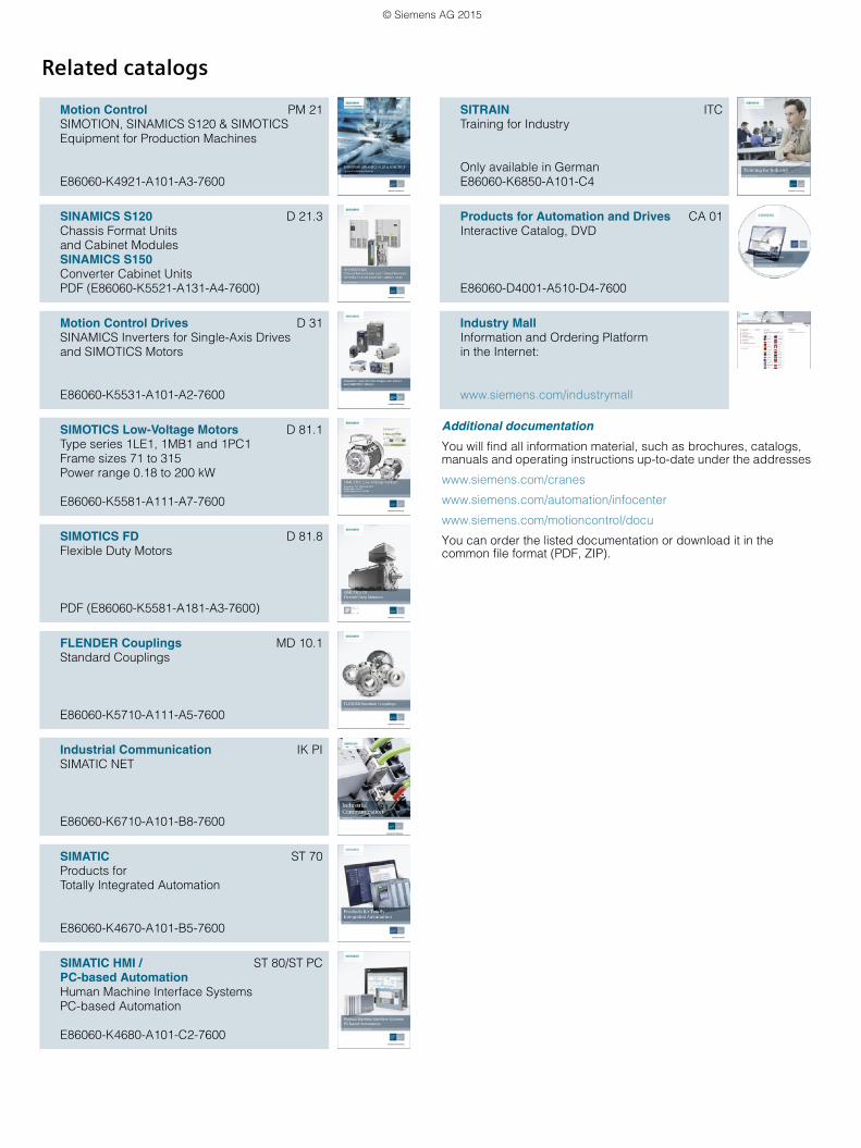
Related catalogs
Motion Control PM 21SIMOTION, SINAMICS S120 & SIMOTICSEquipment for Production Machines
E86060-K4921-A101-A3-7600
SINAMICS S120 D 21.3Chassis Format Unitsand Cabinet ModulesSINAMICS S150Converter Cabinet UnitsPDF (E86060-K5521-A131-A4-7600)
Motion Control Drives D 31SINAMICS Inverters for Single-Axis Drivesand SIMOTICS Motors
E86060-K5531-A101-A2-7600
SIMOTICS Low-Voltage Motors D 81.1Type series 1LE1, 1MB1 and 1PC1Frame sizes 71 to 315Power range 0.18 to 200 kW
E86060-K5581-A111-A7-7600
SIMOTICS FD D 81.8Flexible Duty Motors
PDF (E86060-K5581-A181-A3-7600)
FLENDER Couplings MD 10.1Standard Couplings
E86060-K5710-A111-A5-7600
Industrial Communication IK PISIMATIC NET
E86060-K6710-A101-B8-7600
SIMATIC ST 70Products forTotally Integrated Automation
E86060-K4670-A101-B5-7600
SIMATIC HMI / ST 80/ST PCPC-based Automation Human Machine Interface SystemsPC-based Automation
E86060-K4680-A101-C2-7600
Additional documentation
You will find all information material, such as brochures, catalogs, manuals and operating instructions up-to-date under the addresses
www.siemens.com/cranes
www.siemens.com/automation/infocenter
www.siemens.com/motioncontrol/docu
You can order the listed documentation or download it in the common file format (PDF, ZIP).
SITRAIN ITCTraining for Industry
Only available in GermanE86060-K6850-A101-C4
Products for Automation and Drives CA 01Interactive Catalog, DVD
E86060-D4001-A510-D4-7600
Industry Mall Information and Ordering Platformin the Internet:
www.siemens.com/industrymall
© Siemens AG 2015

SIMOCRANE crane technology platform 1
SIMOCRANE Standard Technology 2
SIMOCRANE Advanced Technology 3
SIMOCRANE CMS Crane Management System 4
SIMOCRANE application examples 5
Drive systems 6
SIMOTICS motors for cranes 7
Services and documentation 8
AppendixSIMOCRANE symbols
9
Drive and Control Components for Cranes
Cranes
Catalog CR 1 · 2015
Supersedes:Catalog CR 1 · 2012Catalog News CR 1 N · March 2013 chapters 1, 2, 3 and 5
Refer to the Industry Mall for current updates of this catalog:www.siemens.com/industrymall
The products contained in this catalog can also be found in the Interactive Catalog CA 01.Article No.: E86060-D4001-A510-D4-7600
Please contact your local Siemens branch.
© Siemens AG 2015
The products and systems described in this catalog are manufactured/distributed under application of a certified quality management system in accordance with DIN EN ISO 9001 and DIN EN ISO 14001(Certified Registration No. 002241). The cer-tificate is recognized by all IQNet countries.
© Siemens AG 2015

2 Siemens CR 1 · 2015
Efficient automation starts with efficient engineering.
Totally Integrated Automation: Efficiency driving productivity.
Efficient engineering is the first step toward better production that is faster,
more flexible, and more intelligent. With all components interacting efficiently,
Totally Integrated Automation (TIA) delivers enormous time savings right from
the engineering phase. The result is lower costs, faster time-to-market, and
greater flexibility.
© Siemens AG 2015
3Siemens CR 1 · 2015
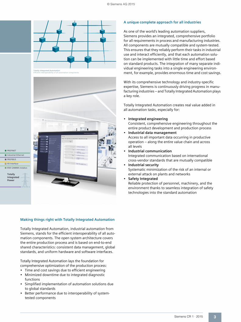
Totally Integrated AutomationEfficient interoperability of all automation components
Making things right with Totally Integrated Automation
Totally Integrated Automation, industrial automation from Siemens, stands for the efficient interoperability of all auto-mation components. The open system architecture covers the entire production process and is based on end-to-end shared characteristics: consistent data management, global standards, and uniform hardware and software interfaces.
Totally Integrated Automation lays the foundation for comprehensive optimization of the production process:• Time and cost savings due to efficient engineering• Minimized downtime due to integrated diagnostic
functions• Simplified implementation of automation solutions due
to global standards• Better performance due to interoperability of system-
tested components
A unique complete approach for all industries
As one of the world's leading automation suppliers, Siemens provides an integrated, comprehensive portfolio for all requirements in process and manufacturing industries. All components are mutually compatible and system-tested. This ensures that they reliably perform their tasks in industrial use and interact efficiently, and that each automation solu-tion can be implemented with little time and effort based on standard products. The integration of many separate indi-vidual engineering tasks into a single engineering environ-ment, for example, provides enormous time and cost savings.
With its comprehensive technology and industry-specific expertise, Siemens is continuously driving progress in manu-facturing industries – and Totally Integrated Automation plays a key role.
Totally Integrated Automation creates real value added in all automation tasks, especially for:
• Integrated engineeringConsistent, comprehensive engineering throughout the entire product development and production process
• Industrial data managementAccess to all important data occurring in productive operation – along the entire value chain and across all levels
• Industrial communicationIntegrated communication based on international cross-vendor standards that are mutually compatible
• Industrial securitySystematic minimization of the risk of an internal or external attack on plants and networks
• Safety IntegratedReliable protection of personnel, machinery, and the environment thanks to seamless integration of safety technologies into the standard automation
© Siemens AG 2015

4 Siemens CR 1 · 2015
Answers for industry.
Siemens Industry answers the challenges in the manufacturing
and the process industry as well as in the building automation
business. Our drive and automation solutions based on Totally
Integrated Automation (TIA) and Totally Integrated Power (TIP)
are employed in all kinds of industry. In the manufacturing
and the process industry. In industrial as well as in functional
buildings.
Siemens offers automation, drive, and low-voltage switching technology as well as industrial software from stan-dard products up to entire industry solu-tions. The industry software enables our industry customers to optimize the en-tire value chain – from product design and development through manufacture and sales up to after-sales service. Our electrical and mechanical components offer integrated technologies for the en-tire drive train – from couplings to gear units, from motors to control and drive solutions for all engineering industries. Our technology platform TIP offers ro-bust solutions for power distribution.
Check out the opportunities our automation and drive solutions provide. And discover how you can sustainably enhance your competitive edge with us.
© Siemens AG 2015

Siemens CR 1 · 2015
11/2 Pre-configured crane control modules
for controlling and automating all types of crane
1/2 Overview1/3 More information
1/4 Crane solutions – Components in the application
1/4 Harbor cranes1/6 Industrial cranes
1/8 SIMOCRANE Standard Technology1/9 SIMOCRANE Basic Technology1/9 SIMOCRANE Drive-Based Technology
1/10 SIMOCRANE Advanced Technology1/10 SIMOCRANE ECO Technology1/10 SIMOCRANE Sway Control Systems1/10 SIMOCRANE TPS Truck Positioning System
1/11 SIMOCRANE CMS Crane Management System
1/11 Overview
1/12 SIMOCRANE application examples1/12 Overview
1/12 Drive systems1/12 Overview
1/12 SIMOTICS motors1/12 Overview
SIMOCRANE crane technology platform
© Siemens AG 2015
1/2 Siemens CR 1 · 2015
1
SIMOCRANE crane technology platformPre-configured crane control modules for controlling and automating all types of crane
■ Overview
Competent and innovative
Crane technology and lifting gear at Siemens have a long tradi-tion. As far back as 1891, Siemens had equipped a 1.5 t slewing crane with regenerative feedback into the line supply.
With our drive technology today we can achieve a lifting capa-city of much more than 14000 t and a hoisting gear speed in excess of 180 m/min.
Trends and requirements
We create significant customer benefits through savings in fuel costs and reduction of CO2 emissions with our rubber tired gan-try cranes thanks to our ECO concept. With our automation and safety concepts we implement automatic guided crane opera-tion.
The rapid growth of worldwide container transport with ever shorter cargo handling times places new demands on crane manufacturers, system integrators and operators of harbor cranes. Mastering large dimensions, high speeds and heavy loads despite highly demanding precision and safety require-ments and all imaginable climatic environmental conditions is a characteristic challenge for this field of application.
The industrial environment is characterized by a wide variety of crane types and load suspension devices. Precision and safety are paramount here, but throughput of goods and availability are also important factors. Depending on the type of goods to be transported, careful transport and damage prevention can be a decisive factor. Industrial cranes are often part of a process chain (e.g. ladle crane) or are integrated into system landscapes of a logistical type (e.g. warehouse management).
Siemens is setting standards in energy efficiency and energy management
Rising energy costs and reduction of CO2 emissions are also concerns that demand innovative economical and environmen-tally sound solutions. Regenerative systems, energy-efficient motors, as well as hybrid drives with intelligent energy manage-ment system are today's solutions for the future.
Platform concept
In order to meet these requirements, Siemens has developed the SIMOCRANE crane technology platform. With the solutions developed by Siemens we master the challenge of shorter and shorter handling times for loads combined with reduced energy requirements.
Standardization and specialization
As one of the leading experts in the industry, Siemens offers innovative SINAMICS drive and control systems for this purpose. On this platform, the modular, maintenance-friendly drive and control components of SIMOCRANE form the basis for control-ling the motion of a crane.
The portfolio is supplemented with a series of technology op-tions of SIMOCRANE Advanced Technology which, in a suitable combination, optimize operation of a crane and increase the availability.
The concept of a modular technology platform also contributes to the shortening of the configuring and commissioning times.
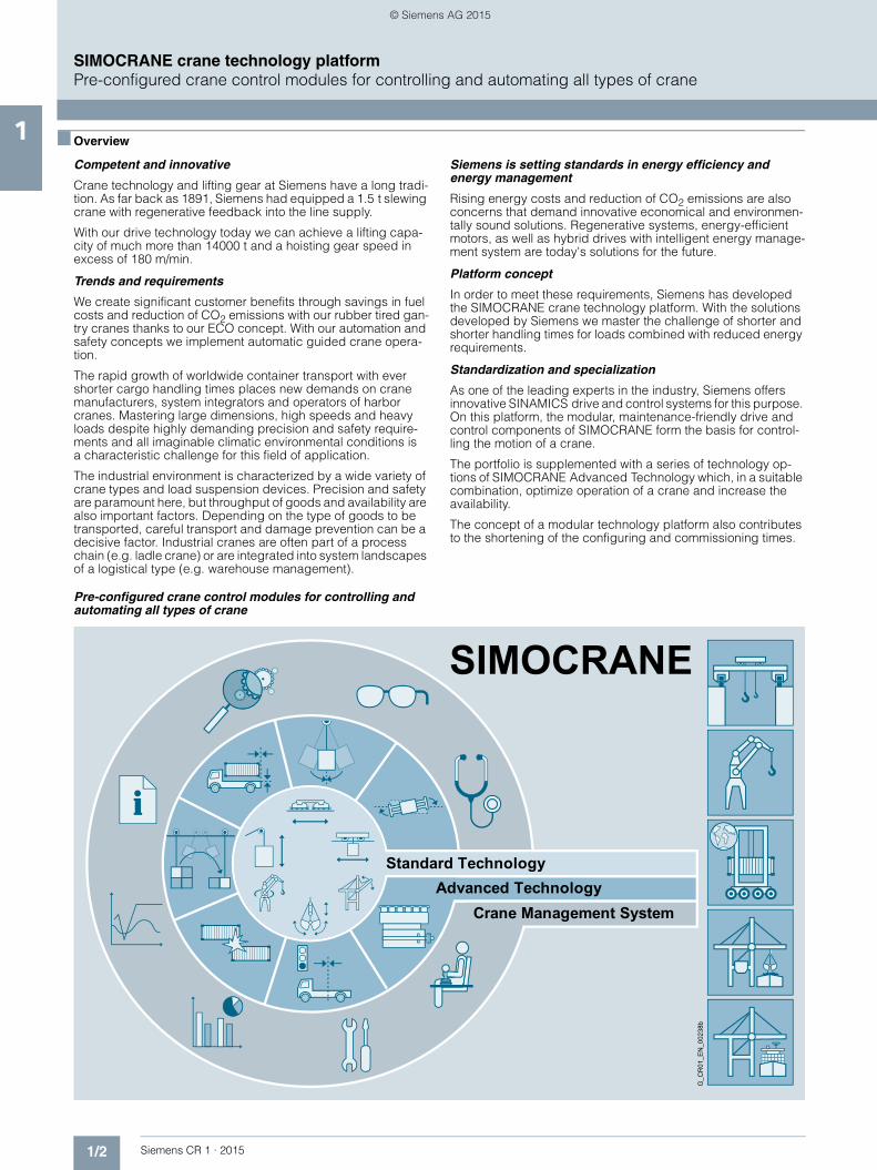
Pre-configured crane control modules for controlling and automating all types of crane
G_C
R01
_EN
_002
38b
Crane Management SystemAdvanced Technology
Standard Technology
SIMOCRANE
© Siemens AG 2015
1/3Siemens CR 1 · 2015
1■ Overview (continued)
SIMOCRANE crane technology platformPre-configured crane control modules for controlling and automating all types of crane
Scalable in hardware and software
Our products and solutions cover the requirements of cranes in dockside applications (container loading and unloading, stack-ing mode and grab mode), as well as in industrial applications in the steel and paper industries (ladle cranes, winding applica-tions), in shipbuilding (Goliath cranes) and in numerous other in-dustrial applications. Due to their scalability they support cus-tomers both in the implementation of complex large cranes with high drive outputs of up to several 1000 kW and demanding functional scope (sway control, automation), as well as simpler crane types with lower outputs of just a few kW and a low degree of automation (manual operation).
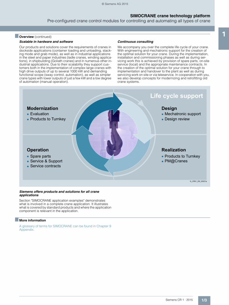
Continuous consulting
We accompany you over the complete life cycle of your crane. With engineering and mechatronic support for the creation of the optimal solution for your crane. During the implementation, installation and commissioning phases as well as during ser-vicing work this is achieved by provision of spare parts, on-site service (local) and the appropriate maintenance contracts. In the creation of the optimal solution for your crane through to implementation and handover to the plant as well as during servicing work on site or via teleservice. In cooperation with you, we also develop concepts for modernizing and retrofitting old crane systems.
Siemens offers products and solutions for all crane applications
Section "SIMOCRANE application examples" demonstrates what is involved in a complete crane application. It illustrates what is covered by standard products and where the application component is relevant in the application.
■ More information
A glossary of terms for SIMOCRANE can be found in Chapter 9 Appendix.
Products to TurnkeyPM@Cranes
Mechatronic supportDesign review
Service contractsService & SupportSpare parts
EvaluationProducts to Turnkey
Modernization
Operation Realization
Design
Life cycle support
G_CR01_EN_00321a
© Siemens AG 2015

1/4 Siemens CR 1 · 2015
1
SIMOCRANE crane technology platformCrane solutions – Components in the application
Harbor cranes
■ Overview
Application range
Container cranes
• STS (ship-to-shore) cranes
Grab cranes
• GSU (grab ship unloader) cranes
Stacking cranes
• ASC (automated stacking cranes)
• RTG (rubber tired gantry) cranes
• RMG (rail mounted gantry) cranes
Example: STS crane, lifting capacity up to 120 t, trolley speed up to 250 m/min
Crane topology
Drive system:SINAMICS S120
Controller:SIMOTION D
SIMATIC S7 I/O: PROFIBUS/PROFINET
HMI/diagnostics:SIMOCRANE CMS with SIMATIC WinCC
656557655412321
G_C
R01
_EN
_003
23c
DC link
CX32-2 Controller Extension
SMC30 Sensor Module Cabinet-MountedMotor Module in chassis formatSIMOTION D435-2
CU320-2 Control Unit Active Line Module in chassis formatActive Interface Module in chassis format
Line contactor
Crane switch
Trans-former
Trans-former
Auxiliarypower supply
Infeed Hoisting gear Gantry Trolley
Boom
SIMATIC S7-300
Industrial Ethernet PROFIBUS
DRIVE-CLiQ
SIMOCRANE CMS
SIMATIC ET 200
654 7
321
© Siemens AG 2015
1/5Siemens CR 1 · 2015
1■ Overview (continued)
SIMOCRANE crane technology platformCrane solutions – Components in the application
Harbor cranes
Drive systems
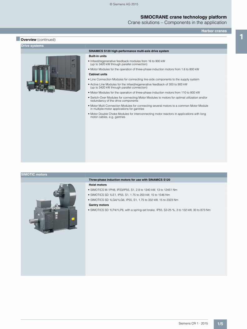
SINAMICS S120 high-performance multi-axis drive system
Built-in units
• Infeed/regenerative feedback modules from 16 to 900 kW(up to 3420 kW through parallel connection)
• Motor Modules for the operation of three-phase induction motors from 1.6 to 800 kW
Cabinet units
• Line Connection Modules for connecting line-side components to the supply system
• Active Line Modules for the infeed/regenerative feedback of 300 to 900 kW (up to 3420 kW through parallel connection)
• Motor Modules for the operation of three-phase induction motors from 110 to 800 kW
• Switch-Over Modules for connecting Motor Modules to motors for optimal utilization and/or redundancy of the drive components
• Motor Multi Connection Modules for connecting several motors to a common Motor Module in multiple-motor applications for gantries
• Motor Double Choke Modules for interconnecting motor reactors in applications with long motor cables, e.g. gantries
SIMOTIC motors
Three-phase induction motors for use with SINAMICS S120
Hoist motors
• SIMOTICS M-1PH8, IP23/IP55, S1, 2.8 to 1340 kW, 13 to 12451 Nm
• SIMOTICS SD 1LE1, IP55, S1, 1.75 to 200 kW, 15 to 1546 Nm
• SIMOTICS SD 1LG4/1LG6, IP55, S1, 1.75 to 332 kW, 15 to 2323 Nm
Gantry motors
• SIMOTICS SD 1LP4/1LP6, with a spring-set brake, IP55, S3-25 %, 3 to 132 kW, 30 to 873 Nm
© Siemens AG 2015

1/6 Siemens CR 1 · 2015
1
SIMOCRANE crane technology platformCrane solutions – Components in the application
Industrial cranes
■ Overview
Application range
Ladle cranes
Bridge cranes
• OHBC (overhead bridge cranes)
Goliath cranes
Example: Ladle crane, lifting capacity 200 - 500 t, gantry speed approx. 60 m/min
Crane topology
Drive system:SINAMICS S120
Controller:SIMOTION DSIMATIC S7
I/O: PROFIBUS/PROFINET
HMI/diagnostics:SIMOCRANE CMS with SIMATIC WinCC
6 656554123
G_C
R01
_EN
_003
22c
DC link
SMC30 Sensor Module Cabinet-Mounted
Motor Module in chassis format
SIMOTION D435-2
CU320-2 Control Unit
Active Line Module in chassis format
Active Interface Module in chassis format
Line contactor
Crane switch
Transformer
Infeed Hoisting gear GantryTrolley
6
5
4
3
2
1
SIMOCRANE CMSSIMATIC S7-300
PROFIBUS
DRIVE-CLiQ
SIMATIC ET 200
© Siemens AG 2015

1/7Siemens CR 1 · 2015
1■ Overview (continued)
SIMOCRANE crane technology platformCrane solutions – Components in the application
Industrial cranes
Drive systems
SINAMICS S120 high-performance multi-axis drive system
Built-in units
• Infeed/regenerative feedback modules from 16 to 900 kW (up to 3420 kW through parallel connection)
• Motor Modules for the operation of three-phase induction motors from 1.6 to 800 kW
Cabinet units
• Line Connection Modules for connecting line-side components to the supply system
• Active Line Modules for the infeed/regenerative feedback of 300 to 900 kW (up to 3420 kW through parallel connection)
• Motor Modules for the operation of three-phase induction motors from 110 to 800 kW
• Switch-Over Modules for connecting Motor Modules to motors for optimal utilization and/or redundancy of the drive components
• Motor Multi Connection Modules for connecting several motors to a common Motor Module in multiple-motor applications for gantries
• Motor Double Choke Modules for interconnecting motor reactors in applications with long motor cables, e.g. gantries
Power Modules
• AC/AC built-in units from 0.37 to 200 kW
SIMOTIC motors
Three-phase induction motors for use with SINAMICS S120
Hoist motors
• SIMOTICS M-1PH8, IP23/IP55, S1, 2.8 to 1340 kW, 13 to 12451 Nm
• SIMOTICS SD 1LE15/16, IP55, S1, 1.75 to 200 kW, 15 to 1546 Nm
• SIMOTICS SD 1LG4/1LG6, IP55, S1, 1.75 to 332 kW, 15 to 2323 Nm
© Siemens AG 2015

1/8 Siemens CR 1 · 2015
1
SIMOCRANE crane technology platformSIMOCRANE Standard Technology
■ Overview
SIMOCRANE Standard Technology
SIMOCRANE Standard Technology supports optimized motion control of different types of crane.
Siemens offers the drive-based mid-performance solution with a compact functional scope SIMOCRANE Drive-Based Technology and the high-performance solution SIMOCRANE Basic Technology, which you can expand using SIMOCRANE Advanced Technology.
Motors
ControlSIMOTION D
Drive systemSINAMICS S120
VisualizationSIMOCRANE CMS
G_CR01_EN_00239c
© Siemens AG 2015

1/9Siemens CR 1 · 2015
1■ Overview (continued)
SIMOCRANE crane technology platformSIMOCRANE Standard Technology
SIMOCRANE offers scalable technology modules for crane automation to increase productivity. The technology module basis is SIMOCRANE Basic Technology which can be ex-panded with the SIMOCRANE Advanced Technology modules such as Sway Control, Skew Control and Truck Positioning.
The different modules enable the applications required in the crane environment for automation of manual, semi or fully auto-matic cranes to be represented.
SIMOCRANE Basic Technology enables and optimizes the motion control of the different axes of a crane, also interactively. The software concept is modular, which makes it easier to im-plement different crane types. The hardware platform for SIMOCRANE Basic Technology is the drive-based SIMOTION D Motion Controller. Together with the SINAMICS S120 drives fam-ily, SIMOCRANE offers a high-performance drive system for total control of the motion and therefore provides the platform for automation of the crane.
The software modules for the drives are a component part of SIMOCRANE Basic Technology:• Hoist• Gantry• Trolley• Slewing gear• Grab• Jib (boom hoist) or luffing gear
SIMOCRANE Drive-Based Technology is drive-based and offers a compact functional scope within the SINAMICS environment, which can also be extended with the SIMOCRANE Drive-Based Sway Control.
Highlights of Drive-Based Technology are fast commissioning by using standard applications and a high degree of flexibility through the appropriate adaptation options.
SIMOCRANE Drive-Based Technology encompasses the follow-ing features:• All of the functions that have been proven in practice and
required for mid-performance applications are available on the SINAMICS platform for parameterization
• Pre-configured standard applications for hoist and trolley/gantry with control via PROFIBUS DP or via I/O signals ("ready-to-run", only have to be parameterized using script)
• Can be adapted for customer-specific requirements "ready-to-apply" (for adaptation by the user).
SIMOCRANE Basic Technology
• SIMOTION D435-2 and CX32-2 hardware
• Engineering software
• SIMOTION SCOUT
G_C
R01
_XX
_002
04b
SIMOCRANE Drive-Based Technology
• SINAMICS CU310-2 hardware and Power Modules
• Engineering software
• SINAMICS STARTER
G_C
R01
_XX
_003
36a
© Siemens AG 2015

1/10 Siemens CR 1 · 2015
1
SIMOCRANE crane technology platformSIMOCRANE Advanced Technology
■ Overview
SIMOCRANE Advanced Technology
Apart from the drive technology, technological supplementary functions and sensor-based automation components are gain-ing in importance in the fulfillment of current market require-ments. An important trend with cranes is the increasing degree of automation and simultaneous reduction in CO2 values.
SIMOCRANE Advanced Technology comprises optional addi-tional components for increasing productivity and enhancing safety for personnel and machines.
Perfectly tuned SIMOCRANE modules allow different depths of automation to be achieved as well as CO2 emissions to be reduced.
In mobile cranes, diesel generators are used conventionally in constant speed mode for generating electrical power. With SIMOCRANE ECO Technology, diesel generators are operated at speeds dependent on the load. This results in reduced fuel consumption and, therefore, savings in operating costs and reduced emissions.
Each movement of a crane with cable guides results in the load swaying and therefore represents a risk to humans and property. Transport processes also take longer to complete. A sway control system can be used to make the transport processes more effective and safer.
SIMOCRANE offers a high-performance sway control system with different operating modes that ensures a high degree of safety for persons, transport goods and equipment.
Automatic sway control relieves the crane driver and also ensures faster and more accurate positioning of the load.
In the case of automated motion control, a sway control system is essential for avoiding the risk of collisions and accidents. In the case of grab cranes, a completely controlled sway is neces-sary.
The high-performance solution can be applied for different type of cranes, like STS, GSU and OHBC cranes. Furthermore, SIMOCRANE meets also the challenge of mid-performance market with its drive-based solution SIMOCRANE Drive-Based Sway Control. Its main function is to damp sway in manual operation, so that it can recieve the crane driver and increase productivity.
Positioning of transport vehicles, comprising trucks with container trailers, must be performed smoothly and without delay.
At terminals which use trucks with container trailers for transpor-tation, drivers are instructed manually or must rely on their judg-ment. This has a detrimental effect on both personnel safety and the duration of positioning tasks.
SIMOCRANE ECO Technology
SIMOCRANE Sway Control Systems
• Integrated solution with SIMOTION D
• Standalone solution with SIMOTION C
• Drive-Based solution with SINAMICS S120
SIMOCRANE TPS Truck Positioning System
© Siemens AG 2015

1/11Siemens CR 1 · 2015
1
SIMOCRANE crane technology platformSIMOCRANE CMS Crane Management System
■ Overview
SIMOCRANE CMS Crane Management System The SIMOCRANE CMS Crane Management System is a PC-based visualization software (SCADA) providing operational data and diagnostic information for crane operators, mainte-nance personnel, and plant operators.
It also supports maintenance personnel evaluating operational hours and load cycle counters for the entire terminal using the Remote Crane Management System. Crane-specific market applications are delivered with SIMOCRANE CMS, e.g. Replay function for playing back the crane operator actions, container operating data statistics and reporting, own designed objects for crane applications, remote crane diagnosis, etc.
With SIMOCRANE CMS Siemens relies on well-established standard of SIMATIC products from the industrial sector. The crane management system is based on SIMATIC WinCC, the SCADA software from Siemens, offering all functions of an advanced visualization software.
Typical fields of application are harbor and industrial crane systems.
The crane management system SIMOCRANE CMS includes various components:• Crane controller
- CMS standard package for local installation on the crane (e.g. fault diagnositics, Replay)
- CMS options (e.g. multi-terminal operation, advanced reporting)
• Management level- RCMS server and client stations for remote operation
SIMOCRANE CMS
• Hardware SIMATIC IPC(Rack PC, Microbox, Touch PC)
• SoftwareSIMOCRANE CMS + SIMATIC WinCC + options/AddOns
G_C
R01
_XX
_002
40a
G_CR01_EN_00381
Online help system
Integration of customer-specific information
Site documentation reference
Information
Replay function/Playback
Advanced trend monitoring
Data analysis
Process value recording
Operation recording
Acquisition & ReportingOperational data
Advanced diagnostics
Instructions & Notes
Operational hours & Counters
Maintenance assistance
Statistical information
Historical data
Information reference
Alarm & Event lists
Fault diagnosticsControl monitoring &
Operation
© Siemens AG 2015

1/12 Siemens CR 1 · 2015
1
SIMOCRANE crane technology platformSIMOCRANE application examples – Drive systems – Motors
■ Overview
SIMOCRANE application examples
SIMOCRANE offers a range of perfectly interacting products that can be combined to fulfill a wide range of different requirements.The high degree of scalability is a decisive advantage for imple-menting crane applications ranging from simple, manual appli-cations to semi-automatic or fully-automatic crane applications. The diversity and combination possibilities of SIMOCRANE products for implementing the different requirements will be illustrated here.
Through the use of Basic Technology and different Advanced Technology functions, different applications can be implemen-ted and various degrees of automation can be achieved.
Besides the high-performance solution SIMOCRANE provides also a mid-performance solution as well.
Drive systems
SINAMICS is the drive platform from Siemens designed for mechanical and plant engineering.
Crane applications place demanding requirements on the dynamic response and integration capability of additional technology functions.
SINAMICS S120 provides the solution for these demanding tasks in combination with the technologies of SIMOCRANE. SINAMICS S120 is characterized by the following properties:• Modularity• Combination capability• High performance in terms of output and closed-loop control
Multi-axis drives with higher-level motion control solutions for cranes can be implemented with the SINAMICS S120 modular system as easily as single-drive solutions.
SIMOTICS motors
Siemens offers the ideal SIMOTICS motor for any application.
The challenge in the field of crane drives is to create increasingly compact and dynamic motors in a wide range of outputs and variants. Siemens offers a broad spectrum of hoist and gantry motors to satisfy these demands. A suitable SIMOTICS motor of induction design is available for every Motion Control task – with ratings ranging from 2.2 to 1340 kW.
All SIMOTICS motors for Motion Control applications are opti-mally designed to operate with the SINAMICS S120 drive sys-tem.
SINAMICS S120 built-in units for crane applications
SINAMICS S120 Cabinet Modules for crane applications
Three-phase induction motors
© Siemens AG 2015

Siemens CR 1 · 2015
22/2 SIMOCRANE Basic Technology2/2 Motion control2/2 Overview2/2 Benefits2/2 Application2/3 Design2/7 Selection and ordering data2/7 More information2/8 Hardware
SIMOTION D435-2 Control Unit2/8 Overview2/8 Benefits2/9 Design2/9 Integration2/10 Technical specifications2/12 Hardware
SIMOTION CX32-2 Controller Extension2/12 Overview2/12 Technical specifications2/14 SIMOTION SCOUT Engineering Software2/14 Overview2/16 Design
2/19 SIMOCRANE Drive-Based Technology2/19 Motion control2/19 Overview2/19 Benefits2/19 Application2/19 Design2/21 Selection and ordering data2/21 More information2/22 Engineering Software2/22 Overview2/22 Application2/24 Design
Security information
Siemens provides products and solutions with industrial security functions that sup-port the secure operation of plants, solutions, machines, equipment and/or networks. They are important components in a holistic industrial security concept. With this in mind, Siemens’ products and solu-tions undergo continuous development. Siemens recommends strongly that you regularly check for product updates.
For the secure operation of Siemens pro-ducts and solutions, it is necessary to take suitable preventive action (e.g. cell protec-tion concept) and integrate each compo-nent into a holistic, state-of-the-art industrial security concept. Third-party products that may be in use should also be considered. For more information about industrial secu-rity, visit http://www.siemens.com/industrialsecurity.
To stay informed about product updates as they occur, sign up for a product-specific newsletter. For more information, visit http://support.automation.siemens.com.
SIMOCRANE Standard Technology
© Siemens AG 2015
2/2 Siemens CR 1 · 2015
2
SIMOCRANE Standard TechnologySIMOCRANE Basic Technology
Motion control
■ Overview
Crane applications
SIMOCRANE Basic Technology is a system of hardware and software packages for automating cranes that supports you in achieving maximum performance with crane applications. The solution has the following features:• The SIMOCRANE Basic Technology comprises the following
standard functions and covers the motion control of all of the main drives of a crane:- Hoist- Gantry- Trolley- Slewing gear- Grab- Jib (boom hoist) or luffing gear
• All of the functions proven in practice are now implemented on the SIMOTION platform. Furthermore, the latest requirements have been taken into account.
• New closed-loop control concept for synchronous operation and positioning with position controller
• Can be adapted to customer-specific requirements, a package supports both:- "Ready-to-run" (parameters have only to be assigned) as
well as- "Ready-to-apply" (adapted by the user)
• The technological basis is the SIMOTION D Motion Control System.
The SIMOCRANE Basic Technology V3.0 package comprises the following components:
Hardware• Control Unit SIMOTION D435-2 with SINAMICS firmware
version as of V4.5
CompactFlash card• Current firmware version• Licenses
- SIMOTION MultiAxes (for Motion Control)- SIMOTION Crane Basic Technology (for functions in the
Crane DCC Library)
CD-ROM with• Setup with Crane DCC Library and online help• Crane FB Library• Standard applications, e.g. for container quay crane (STS -
ship to shore) or ship unloading crane (GSU - grab ship unloader), etc.
• SIMOTION D4x5-2 V4.3.1 and SINAMICS V4.5 firmware• Documentation
Properties of SIMOCRANE Basic Technology V3.0:• Can be operated with SINAMICS DC Master (DCM) via
PROFINET• Improved usability, e.g. auto-setting function for commis-
sioning• Virtual internal SIMATIC S7 interface to reduce the external
control hardware• Web-based tool for commissioning and diagnostics• Expanded and optimized functionality, e.g. adjustable jerk for
SIMATIC S7
■ Benefits
SIMOCRANE Basic Technology provides the following benefits:• Standard applications significantly reduce the time for
engineering ("ready-to-run")• Easy adaptation and expansion for customized requirements
("ready-to-apply")• One platform for all crane technologies (different crane
technologies such as sway control (SIMOCRANE Sway Control) are systematically based on the SIMOCRANE Basic Technology)
Consequently:• The number of interfaces is reduced by using SIMOTION D• Engineering and commissioning costs are reduced• Standardization is made easier
■ Application
The SIMOCRANE Basic Technology software has a modular structure. The application solution can be flexibly implemented for different types of cranes, e.g. for• Harbor cranes
- STS (ship to shore crane, also for double spreader in tandem operation)
- RMG (rail mounted gantry crane)- GSU (grab ship unloader) etc.
• High-performance and mid-performance industrial cranes with crane-specific technology- Coil cranes- Gantry cranes- Waste incineration cranes, etc.
• Modernization with DC drives or a combination of three-phase AC and DC drives- STS (ship to shore crane)- GSU (grab ship unloader)- LSC (lifting and slewing crane)
© Siemens AG 2015

2/3Siemens CR 1 · 2015
2
SIMOCRANE Standard TechnologySIMOCRANE Basic Technology
Motion control
■ Design
Structure of an axis grouping with the SIMOTION D435-2 Motion Control System in the crane application
The following components comprise a SIMOTION D crane appli-cation:• A SIMOTION D435-2 Control Unit, designed for open and
closed-loop control of a multi-axis drive line-up• One or several SIMOTION CX32-2 Controller Extensions for
more than 6 axes (see the application example "Topology of container quay crane" in the "Hardware configuration" section)
• Several SINAMICS S120 Motor Modules (power units) • Several SINAMICS DC Master Power Modules (power units)• Other drive components, such as
- Power supply- Filter- Reactor, etc.
• The connection between SIMOTION D and the SINAMICS S120 Motor Modules which is implemented with DRIVE-CLiQ in a star topology to ensure axis redundancy (see the application example "Topology of container quay crane" → "Hardware configuration").
• A CU320-2 Control Unit for open and closed-loop control of the parallel infeed (up to 4 infeed units)
• One or several SINAMICS S120 Line Modules (in SIMOCRANE Basic Technology, the infeed unit is separately controlled by the SIMATIC S7, see the application example "Topology of container quay crane" → "Hardware configu-ration").
Hardware configuration
The hardware configuration based on the example of a container quay crane on the SIMOTION/SINAMICS platform is shown in the figure below.
The performance of the SIMOTION D hardware allows all crane technologies, not only Basic Technology, but also Advanced Technology, e.g. sway control (SIMOCRANE Sway Control), to be operated from one controller. The individual crane technolo-gies build on each other systematically.
Additional crane technologies of SIMOCRANE are described in Chapter 3 SIMOCRANE Advanced Technology and Chapter 4 SIMOCRANE CMS Crane Management System.
Topology of container quay crane
656557655412321
G_C
R01
_EN
_003
23c
DC link
CX32-2 Controller Extension
SMC30 Sensor Module Cabinet-MountedMotor Module in chassis formatSIMOTION D435-2
CU320-2 Control Unit Active Line Module in chassis formatActive Interface Module in chassis format
Line contactor
Crane switch
TransformerTransformer
Auxiliarypower supply
Infeed Hoisting gear Gantry Trolley
Boom
SIMATIC S7-300
Industrial Ethernet PROFIBUS
DRIVE-CLiQ
SIMOCRANE CMS
SIMATIC ET 200
654 7
321
© Siemens AG 2015

2/4 Siemens CR 1 · 2015
2
■ Design (continued)
SIMOCRANE Standard TechnologySIMOCRANE Basic Technology
Motion control
Configurations with mixed three-phase AC drives (DC/AC) and DC drives (DC/DC) are possible in the SIMOCRANE Basic Technology V3.0. Applications such as these are
frequently found in modernization projects (see the application example "Container crane").
Topology of a container crane with mixed three-phase AC and DC drives (DC/AC)
SMC30 Sensor Module Cabinet-Mounted
Motor Module in chassis formatSIMOTION D435-2CU320-2 Control Unit
Active Line Module in chassis formatActive Interface Module in chassis formatSINAMICS DCM (DC Master)
654
76 76 76
5
7
1 1
3
4
2
3
1
2
Line contactor
Hoisting gear 1
Hoisting gear 2
Boom
Trolley Gantry 1 Gantry 2Crane switch
DC link
TransformerTransformer
Auxiliary power supply
Infeed
G_C
R01
_EN
_003
30a
HMI in cabin
SIMATIC S7-300
SIMATIC ET 200
SIMOCRANE CMS
Industrial Ethernet
PROFINET
PROFIBUS
DRIVE-CLIQ
© Siemens AG 2015

2/5Siemens CR 1 · 2015
2
■ Design (continued)
SIMOCRANE Standard TechnologySIMOCRANE Basic Technology
Motion control
SIMOCRANE Basic Technology software
The SIMOCRANE Basic Technology package not only provides the basic functionality, the SIMOTION Motion Control technology package (for positioning, synchronous operation, etc.) and stan-dard libraries, but also the Crane Basic Technology package complete with 2 libraries. The package also contains several complete standard applications for cranes.
The modular software concept makes it easier to automate dif-ferent crane types. With the help of the open software, all crane-
specific technologies or functions can be supplied to the user in the form of function blocks. The software structure is shown for a coil crane, a container quay crane and a ship unloading crane in the following examples. Each axis of motion is mapped using a function module in the software. Controlling and coordinating the axes are realized at the application level.
Function blocks for coil crane
Function blocks for container quay crane
Coil craneG_CR01_EN_00205b
STATUSCOMMAND
STATCMD STATCMD STATCMD STATCMD
Application level
STATUSCOMMAND
Container quay craneG_CR01_EN_00168b
STATCMD STATCMD STATCMD STATCMD
Application level
© Siemens AG 2015

2/6 Siemens CR 1 · 2015
2
■ Design (continued)
SIMOCRANE Standard TechnologySIMOCRANE Basic Technology
Motion control
Function blocks for ship unloading crane
Each function module (e.g. hoist) has two MCC units and one DCC chart. Two application programs created in the MCC call the necessary function blocks from the "Cranes FB Library" for execution of the function module (e.g. operating mode manage-ment). In a program created by DCC, the setpoint channel for velocity and acceleration/deceleration is set up that takes into account the crane-specific technology (e.g. load-dependent field weakening) cyclically.
The standard application is created according to crane type, e.g. "Container quay crane". For "ready-to-run" users, only parameterization is necessary. For "ready-to-apply" users, this provides the starting point for individual expansions and adaptation to address specific crane applications.
Ship unloading craneG_CR01_EN_00169b
STATUSCOMMAND
STATCMD STATCMD STATCMD STATCMD
Application level
© Siemens AG 2015

2/7Siemens CR 1 · 2015
2
SIMOCRANE Standard TechnologySIMOCRANE Basic Technology
Motion control
■ Selection and ordering data
Scope of delivery
The SIMOCRANE Basic Technology package offers a control system with hardware and software for various crane applica-tions.
Supplementary components
Depending on the application, the following components can be supplied for the open-loop and closed-loop control:
Drive systems SINAMICS S120, motors and connection systems are not included in the package (see Chapter 6 Drive systems). These components must be ordered separately.
Further information on selection and ordering of supplementary components can be found in the following Catalogs:• PM 21 – SIMOTION, SINAMICS S120 & SIMOTICS• D 81.1 – SIMOTICS Low-Voltage Motors• IK PI – Industrial Communication
■ More information
Siemens product support
The latest information about SIMOCRANE products, product support and FAQs can always be found on the Internet at
https://support.industry.siemens.com/cs/→ Product Support → (Enter search term) SIMOCRANE
You can find further information about Crane Application Notes on the Internet at
https://support.industry.siemens.com/cs/→ Application Examples → (Enter search term) Crane
The latest information about SIMOTION products, product sup-port and FAQs can always be found on the Internet at
https://support.industry.siemens.com/cs/→ Product Support → (Enter search term) SIMOTION
The latest information about SINAMICS products, product sup-port and FAQs can always be found on the Internet at
https://support.industry.siemens.com/cs/→ Product Support → (Enter search term) SINAMICS
Notes on licensing
The license depends on the serial number of the memory card (CompactFlash card). The crane application software cannot run without a valid license. Licensing is managed via Siemens Motion Control Web License Manager.
http://www.siemens.com/automation/license
Training
Siemens Cranes offers crane-specific training
http://www.siemens.nl/training/cranes
Description Article No.
SIMOCRANE Basic Technology V3.0for SIMOTION D435-2
6AU1660-4AA20-0AA0
consisting of 1 item each• Hardware
- SIMOTION D435-2 DP/PN• CompactFlash card
with current firmware version and licenses- SIMOTION MultiAxes
(for Motion Control)- SIMOTION Crane
Basic Technology (for functions in the Crane DCC Li-brary)
• CD-ROM with- Setup with Crane DCC Library and
online help- Crane FB Library- Standard applications,
e.g. for a ship to shore crane (STS) or a grab ship unloader (GSU), etc.
- SIMOTION D4x5-2 V4.3.1 and SINAMICS V4.5 firmware
- Documentation
Description Article No.
SIMOTION CX32-2(SINAMICS Controller Extension for SIMOTION D435-2)
6AU1432-2AA00-0AA0
SINAMICS DRIVE-CLiQHub Module DMC20
6SL3055-0AA00-6AA0
SINAMICS SMC 30 Sensor Module Cabinet-Mounted
6SL3055-0AA00-5CA2
SINAMICS Terminal Module TM31 6SL3055-0AA00-3AA1
SIMOTION SCOUT V4.4 HF4 6AU1810-1BA44-0XA0
Option packageDrive Control Chart (DCC) V2.3
6AU1810-1JA23-0XA0
© Siemens AG 2015

2/8 Siemens CR 1 · 2015
2
SIMOCRANE Standard TechnologySIMOCRANE Basic Technology
Hardware SIMOTION D435-2 Control Unit
■ Overview
SIMOTION D is the compact, drive-based version of SIMOTION based on the SINAMICS S120 drives family.
With SIMOTION D, the PLC, Motion Control functions and tech-nology functions as well as the SINAMICS S120 drive software run on a common control hardware.
SIMOTION D435-2 DP/PN (STANDARD performance) are Control Units for multi-axis applications in the power range for up to 32 axes.
■ Benefits
• Cost-effective thanks to the integration of PLC, Motion Control functions and technology functions directly in the drive
• Employs the innovative SINAMICS S120 design• Compact design reduces control cabinet size• Ideally suited to modular and distributed machine concepts• User-friendly operation• Variable networking via a wide range of communication inter-
faces:- Industrial Ethernet, PROFIBUS DP and PROFINET IO
onboard• Powerful thanks to a range of technology functions• Very simple engineering, from drive commissioning to open-
loop control applications and Motion Control applications• Easy to service thanks to CompactFlash card, which can be
easily replaced and contains all data (programs, data, drive parameters)
• Very fast response as the interfaces between PLC and Motion Control are no longer required
© Siemens AG 2015

2/9Siemens CR 1 · 2015
2
SIMOCRANE Standard TechnologySIMOCRANE Basic Technology
Hardware SIMOTION D435-2 Control Unit
■ Design
Interfaces
Display and diagnostics• LEDs to display operating states and errors• 3 measuring sockets • Service switch and mode selector • Diagnostics button
Onboard I/O• 12 digital inputs • 16 digital inputs/outputs (max. 16 as high-speed measuring
inputs, max. 8 as high-speed output cams)
Communication• 6 × DRIVE-CLiQ• 2 × Industrial Ethernet (3 × Industrial Ethernet for D4x5-2 DP),
of which one interface easily accessible at the module front• 2 × PROFIBUS DP• 1 × PROFINET IO (1 interface with 3 ports, with D4x5-2 DP/PN
only)• 2 × USB
Data backup• 1 × slot for SIMOTION CompactFlash card
Further interfaces• Terminals for 24 V electronics power supply
Option modules
With the TB30 Terminal Board, the SIMOTION D4x5-2 Control Units can be extended with 4 digital inputs, 4 digital outputs, 2 analog inputs and 2 analog outputs. The TB30 Terminal Board is plugged into the option slot on the Control Unit. Using the CBE30-2 Communication Board for PROFINET IO, it is possible to equip the SIMOTION D435-2 DP/PN Control Units with a 2nd PROFINET interface with 4 ports.
Applications for a 2nd PROFINET interface:• 2 separate networks (e.g. one local and one higher-level
network)• Address space can be doubled to 2 × 4 Kbyte • Maximum number of connectable devices can be doubled to
2 × 64• Separated to create a fast and a slow bus system/execution
system to efficiently utilize the control performance- PROFINET onboard: SERVOFast and IPOFast- PROFINET via CBE30-2: SERVO/IPO/IPO2
■ Integration
Connection overview SIMOTION D4x5-2
The maximum permissible cable lengths should be taken into account when planning the cable layout. Functional faults can occur when using longer cables. The permissible length of PROFIBUS DP cables depends on the configuration. The DRIVE-CLiQ cables used for the SINAMICS S120 CU320-2 Control Unit can also be used for SIMOTION D4x5-2 Control Units.
6ES7901-4BD00-0XA0
notD425-2
Ethernet
USB
DRIVE-CLiQ
Ethernet node
12 DI, 16 DI/DO
SINAMICS S120 drive components
24 V supply
Programming device (PG)
USB memorystick
PROFIBUS DP node
DRIVE-CLiQ cable
Ethernet cable
PROFIBUS cables
OnboardI/Os
Power supply
PROFINET IO2) CBE30-2(optional)
e.g. SINAMICS S120, ET 200SP
PROFINET IOIRT/RT I/Os
e.g. SINAMICS S120, ET 200SP
PROFINET IOIRT/RT I/Os
G_PM10_EN_00216b
1) X120 only for D4x5-2 DP.2) D4x5-2 DP/PN only (CBE30-2 as second PROFINET interface).3) D4x5-2 DP/PN only.
1)
X100to
X103X104X105
SIMOTIOND4x5-2
X122X132 X142
X124
X136
PROFIBUS DPX126
X135X125
X150 P1P2P3
X1400 P1P2P3P4
X120 P1 X127 P1 X130 P1
PROFINET IO3)
© Siemens AG 2015

2/10 Siemens CR 1 · 2015
2
SIMOCRANE Standard TechnologySIMOCRANE Basic Technology
Hardware SIMOTION D435-2 Control Unit
■ Technical specifications
6AU1435-2AD00-0AA0
Product brand name SIMOTION
Product-type designation D435-2 DP/PN
Performance class of the motion control system
STANDARD Performance
Version of the motion control system Multiple-axis system
PLC and motion control performanceMaximum number of axes 32
Minimum PROFIBUS cycle clock ms 1
Minimum PROFINET send cycle clock ms 0.25
Minimum servo cycle clock ms 0.25
Minimum interpolator cycle clock ms 0.25
Servo/IPO clock cycle, remark 0.5 ms in conjunction with integrated SINAMICS S120 drives (SINAMICS Integrated); 0.25 ms in conjunction with SERVOFAST and IPOFAST
Integrated drive controlMaximum number of axes for integrated drive control• servo 6• vector 6• V/f 12• remark Alternative control modes; drive control based on SINAMICS S120 CU320-2, firmware version V4.x
MemoryRAM (work memory) Mbyte 64
Additional RAM work memory for Java applications
Mbyte 20
RAM disk (load memory) Mbyte 41
Retentive memory kbyte 364
Persistent memory (user data on CF) Mbyte 300
CommunicationDRIVE-CLiQ interfaces 6
USB interfaces 2
Industrial Ethernet interfaces 2
PROFIBUS interfaces 2• remark Equidistant and isochronous; can be configured as master or slave
PROFINET interfaces 1• remark 1 interface with 3 ports onboard 1 interface with 4 ports optional via CBE30-2 functionality:
supports PROFINET IO with IRT and RT; configurable as PROFINET IO Control and/or device; supports media redundancy (MRP and MRPD)
General technical specificationsFan Double fan/battery module included in scope of delivery
DC supply voltage• rated value V 24• permissible range V 20.4 … 28.8
Current consumption, typ. mA 1 000• remark with no load on inputs/outputs, no 24 V supply via DRIVE-CLiQ and PROFIBUS interface
Making current, typ. A 5
Power loss, typ. W 24
Ambient temperature• during long-term storage °C -25 … +55• during transport °C -40 … +70• during operating °C ± 0 … + 55
- remark Maximum installation altitude 4000 m above sea level. Above an altitude of 2000 m, the maximum ambient temperature decreases by 7 °C per 1000 m.
Relative humidity without condensation• during operating phase % 5 … 95
Air pressure hPa 620 … 1 060
Protection class IP IP20
Height mm 380
Width mm 50
Depth mm 270• remark when the spacer is removed 230 mm deep
Net weight g 3 600
© Siemens AG 2015

2/11Siemens CR 1 · 2015
2
■ Technical specifications (continued)
SIMOCRANE Standard TechnologySIMOCRANE Basic Technology
Hardware SIMOTION D435-2 Control Unit
6AU1435-2AD00-0AA0
Product brand name SIMOTION
Product-type designation D435-2 DP/PN
Performance class of the motion control system
STANDARD Performance
Version of the motion control system Multiple-axis system
Digital inputsNumber of digital inputs 12
DC input voltage• rated value V 24• for signal "1" V 15 … 30• for signal "0" V -3 … +5
Electrical isolation Yes• remark Yes, in groups of 6
Current consumption for "1" signal level, typ. mA 9
Input delay time for• signal "0" → "1", typ. µs 50• signal "1" → "0", typ. µs 150
Digital inputs/outputsNumber of digital inputs/outputs 16
Parameterization possibility of the digital inputs/outputs
can be parameterized as DI, as DO, as probe input (max. 16), as cam output (max. 8)
If used as an input
DC input voltage• rated value V 24• for signal "1" V 15 … 30• for signal "0" V -3 … +5
Electrical isolation No
Current consumption for "1" signal level, typ. mA 9
Input delay time for• signal "0" → "1", typ. µs 5• signal "1" → "0", typ. µs 50
Measuring input reproducibility µs 5
Measuring input resolution µs 1
If used as an output
Load voltage• rated value V 24• permissible range V 20.4 … 28.8
Electrical isolation No
Current carrying capacity for each output, max. mA 500
Leakage current, max. mA 2
Output delay for• signal "0" → "1", typ. µs 150• signal "0" → "1", max. µs 400• signal "1" → "0", typ. µs 75• signal "1" → "0", max. µs 150
- remark Data for Vcc = 24 V; load 48 Ohm; "1" = 90 % VOut, "0" = 10 % VOut
Output cam, reproducibility µs 10
Output cam, resolution µs 1
Switching frequency of the outputs for• ohmic load, max. Hz 100• inductive load, max. Hz 2• lamp load, max. Hz 11
Short-circuit protection Yes
Additional technical specificationsBackup of non-volatile data• Backup of retentive data unlimited buffer duration• Buffer time real-time clock 4 days min. • remark longer buffer duration of the real-time clock using a battery
inserted in the double fan/battery module
Approvals• USA cULus• Canada cULus• Australia C-Tick• Korea KCC
© Siemens AG 2015

2/12 Siemens CR 1 · 2015
2
SIMOCRANE Standard TechnologySIMOCRANE Basic Technology
Hardware SIMOTION CX32-2 Controller Extension
■ Overview
The SIMOTION CX32-2 Controller Extension is a module in the SINAMICS S120 booksize format. It enables the extension of the drive-side computing performance of the SIMOTION D4x5-2 Control Units.
The SIMOTION CX32-2 Controller Extension extends the drive computing performance by up to 6 vector or 12 V/f axes. This allows the number of axes of a multi-axis system to be increased according to the requirements of the application.
If required, up to 5 SIMOTION CX32-2 Controller Extensions can be operated on one SIMOTION D435-2 Control Unit.
The SIMOTION CX32-2 Controller Extension is connected to the SIMOTION D435-2 via DRIVE-CLiQ.
Note:
The SIMOTION CX32-2 Controller Extension can only be used with SIMOTION D4x5-2 Control Units. Operation with SIMOTION D4x5 Control Units is not possible.
■ Technical specifications
6AU1432-2AA00-0AA0
Product brand name SIMOTION
Product-type designation CX32-2
Version of the motion control system Controller Extension
Integrated drive controlMaximum number of axes for integrated drive control• servo 6• vector 6• V/f 12• remark Alternative control modes; drive control based on SINAMICS S120 CU320-2, firmware version V4.x
CommunicationInterfaces DRIVE-CLiQ 4
General technical specifications
Fan No fan
DC supply voltage• rated value V 24• permissible range V 20.4 … 28.8
Current consumption, typ. mA 300• remark with no load on inputs/outputs, no 24 V supply via DRIVE-CLiQ interface
Making current, typ. A 1.6
Power loss, typ. W 7
Ambient temperature• during long-term storage °C -25 … +55• during transport °C -40 … +70• during operating °C ± 0 … + 55
- note Maximum installation altitude 4000 m above sea level. Above an altitude of 2000 m, the maximum ambient temperature decreases by 7 °C per 1000 m.
Relative humidity without condensation• during operating phase % 5 … 95
Air pressure hPa 620 … 1 060
Protection class IP IP20
Dimensions height mm 380
Dimensions width mm 25
Depth mm 270• remark when the spacer is removed 230 mm deep
Net weight g 2 600
© Siemens AG 2015

2/13Siemens CR 1 · 2015
2
■ Technical specifications (continued)
SIMOCRANE Standard TechnologySIMOCRANE Basic Technology
Hardware SIMOTION CX32-2 Controller Extension
6AU1432-2AA00-0AA0
Product brand name SIMOTION
Product-type designation CX32-2
Version of the motion control system Controller Extension
Digital inputsNumber of digital inputs 6
DC input voltage• rated value V 24• for signal "1" V 15 … 30• for signal "0" V -3 … +5
Electrical isolation Yes• remark in groups of 6
Current consumption for "1" signal level, typ. mA 9
Input delay for• signal "0" → "1", typ. µs 50• signal "1" → "0", typ. µs 150
Digital inputs/outputsNumber of digital inputs/outputs 4
Parameterization possibility of the digital inputs/outputs
parameterizable as DI, as DO, as probe input (max. 4)
If used as an input
DC input voltage• rated value V 24• for signal "1" V 15 … 30• for signal "0" V -3 … +5
Electrical isolation No
Current consumption for "1" signal level, typ. mA 9
Input delay for• signal "0" → "1", typ. µs 5• signal "1" → "0", typ. µs 50
Measuring input, reproducibility µs 5
Measuring input, resolution µs 1
If used as an output
Load voltage rated value V 24
Load voltage minimum V 20.4
Load voltage maximum V 28.8
Electrical isolation No
Current carrying capacity for each output, max. mA 500
Leakage current, max. mA 2
Output delay for• signal "0" → "1", typ. µs 150• signal "0" → "1", max. µs 400• signal "1" → "0", typ. µs 75• signal "1" → "0", max. µs 100
- remark Data for Vcc = 24 V; load 48 Ohm; "1" = 90 % VOut, "0" = 10 % VOut
Switching frequency of the outputs for• ohmic load, max. Hz 100• inductive load, max. Hz 2• lamp load, max. Hz 11
Short-circuit protection Yes
Additional technical specificationsBackup of non-volatile data• Backup of retentive data unlimited buffer duration
Approvals• USA cULus• Canada cULus• Australia C-Tick• Korea KCC
© Siemens AG 2015

2/14 Siemens CR 1 · 2015
2
SIMOCRANE Standard TechnologySIMOCRANE Basic Technology
SIMOTION SCOUT Engineering Software
■ Overview
SCOUT is the engineering software for SIMOTION that is inte-grated in STEP 7. SCOUT contains all the tools required for con-figuration, parameterization, programming, testing, diagnostics and commissioning of SIMOTION and SINAMICS.
Structured Text
The high-level language ST (Structured Text) provides all lan-guage elements as text commands. This allows well-structured applications to be created.
Crane-specific operations, such as operating mode assignment and management, message frame processing, etc. have been programmed in ST as function blocks and are stored in the "Crane FB Library".
SIMOTION SCOUT
SIMOTION SCOUT with crane applicationG
_CR
01_E
N_0
0171
b
Diagnostics for Testingand Commissioning (Trace)Axis control panel
StructuredText (ST)
Motion ControlChart (MCC)
Hardware and NetworkConfiguration
Creation of TechnologyObjects
SCOUT
SIMOCRANEBasic Technology(Option)
Configuration / Parameterization
ProgrammingProject Management
Testing and Commissioning
Workbench
Creation of Cams(Basic)
Drive ControlChart (DCC)
STARTER Drives andCommissioning Tool
Crane Package(SW)
Load dependentfield weakening
Pre limit switch
Start pulse
DCC Library
Control Axis
FB Library
STS Crane
Ship Unloader Crane
AP Software
Operation Mode
TelegramS7 To SIMOTION
© Siemens AG 2015
2/15Siemens CR 1 · 2015
2
■ Overview (continued)
SIMOCRANE Standard TechnologySIMOCRANE Basic Technology
SIMOTION SCOUT Engineering Software
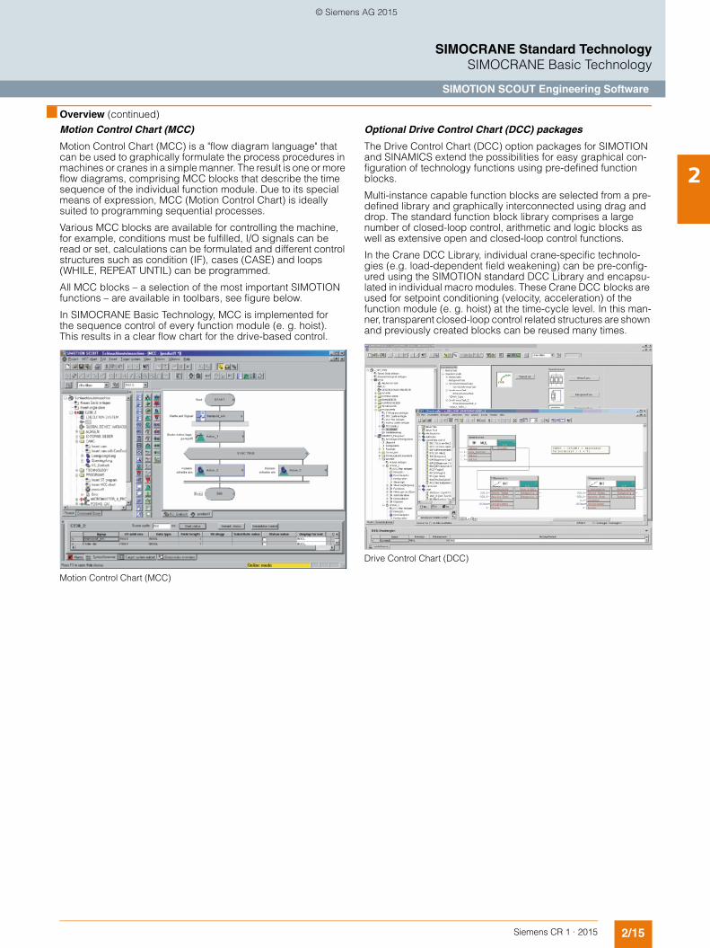
Motion Control Chart (MCC)
Motion Control Chart (MCC) is a "flow diagram language" that can be used to graphically formulate the process procedures in machines or cranes in a simple manner. The result is one or more flow diagrams, comprising MCC blocks that describe the time sequence of the individual function module. Due to its special means of expression, MCC (Motion Control Chart) is ideally suited to programming sequential processes.
Various MCC blocks are available for controlling the machine, for example, conditions must be fulfilled, I/O signals can be read or set, calculations can be formulated and different control structures such as condition (IF), cases (CASE) and loops (WHILE, REPEAT UNTIL) can be programmed.
All MCC blocks – a selection of the most important SIMOTION functions – are available in toolbars, see figure below.
In SIMOCRANE Basic Technology, MCC is implemented for the sequence control of every function module (e. g. hoist). This results in a clear flow chart for the drive-based control.
Motion Control Chart (MCC)
Optional Drive Control Chart (DCC) packages
The Drive Control Chart (DCC) option packages for SIMOTION and SINAMICS extend the possibilities for easy graphical con-figuration of technology functions using pre-defined function blocks.
Multi-instance capable function blocks are selected from a pre-defined library and graphically interconnected using drag and drop. The standard function block library comprises a large number of closed-loop control, arithmetic and logic blocks as well as extensive open and closed-loop control functions.
In the Crane DCC Library, individual crane-specific technolo-gies (e.g. load-dependent field weakening) can be pre-config-ured using the SIMOTION standard DCC Library and encapsu-lated in individual macro modules. These Crane DCC blocks are used for setpoint conditioning (velocity, acceleration) of the function module (e. g. hoist) at the time-cycle level. In this man-ner, transparent closed-loop control related structures are shown and previously created blocks can be reused many times.
Drive Control Chart (DCC)
© Siemens AG 2015

2/16 Siemens CR 1 · 2015
2
SIMOCRANE Standard TechnologySIMOCRANE Basic Technology
SIMOTION SCOUT Engineering Software
■ Design
The function library
The "Crane DCC Library" comprises a collection of blocks (e.g. load-dependent field-weakening) which are implemented as "Drive Control Charts (DCC)" blocks. DCC is a representation which supports graphic configuring and interconnecting. The functional scope of the crane library is described in detail in the section "Technology functions".
The "Crane FB Library" consists of a collection of blocks (e.g. Operation Mode) which have been programmed in "Structured Text" (ST). These function blocks are called up in the drive-based sequence control at the MCC level.
SIMOTION technology package
Standard applications
The standard applications comprise several ready-to-use con-figured function modules for different crane types, e.g. "Con-tainer quay crane" or "Ship unloading crane". These solutions are "ready-to-run" for the user who only needs to set the parameters appropriately. In the case of large-scale adaptation and expan-sion, these standard applications can be used as a starting point for "ready-to-apply". Expandability and flexibility have therefore been taken into account.
Crane Package(SW)
Load dependentfield weakening
Pre limit switch
Start pulse
DCC Library
Control Axis
FB Library
STS Crane
Ship Unloader Crane
AP Software
Operation Mode
G_C
R01
_EN
_001
70a
TelegramS7 To SIMOTION
© Siemens AG 2015

2/17Siemens CR 1 · 2015
2
■ Design (continued)
SIMOCRANE Standard TechnologySIMOCRANE Basic Technology
SIMOTION SCOUT Engineering Software
Function modules and operating modes
The application software has a modular structure according to crane types. An overview of the function modules, their
operating modes and technology functions used are shown in the following tables.
Overview of the function modules and operating modes
Function modules Number of axes Control modes Operating modes
Hoist 4 • Positioning single axis
• Master-slave operation
• Synchronous operation
• Automatic
• Manual
• Speed controlled (jogging)
• Sway control
• Basic positioning
Trolley 2 • Speed controlled
• Positioning single axis
• Master-slave operation
• Synchronous operation
• Automatic
• Manual
• Speed controlled (jogging)
• Encoderless emergency mode
• Sway control
• Basic positioning
Gantry 2 • Speed controlled
• Positioning single axis
• Master-slave operation
• Synchronous operation
• Automatic
• Manual
• Speed controlled (jogging)
• Encoderless emergency mode
• Basic positioning
Boom 1 • Speed controlled • Speed controlled (jogging)
Holding and closing gear 4 • Speed controlled
• Separate positioning with one axis (holding or closing gear)
• Synchronous operation between both axes
• Speed controlled (jogging)
• Sway control
• Basic positioning
Slewing gear 1 • Speed controlled
• Positioning
• Automatic
• Manual
• Speed controlled (jogging)
• Encoderless emergency mode
• Basic positioning
© Siemens AG 2015

2/18 Siemens CR 1 · 2015
2
■ Design (continued)
SIMOCRANE Standard TechnologySIMOCRANE Basic Technology
SIMOTION SCOUT Engineering Software
Technology functions
Crane-specific technology functions
No. Function Brief description
1 Load-dependent field weakening Using the DCC block, a supplementary speed setpoint is calculated dependent on the load. This speed increase for partial loads above the rated speed is required for cranes to increase the handling capacity.
2 Prelimit switch (selectable limiting) The velocity of the drive can be limited using the DCC block when a pre-defined prelimit switch is reached.
3 Start pulse Using the DCC block, "load sag" when starting hoists with a suspended load is prevented.
4 Switch-over of the ramp-function generator in the field-weaken-ing range and when selecting heavy-duty operation
Using the DCC block, the acceleration and deceleration times are modified for heavy-duty operation or in field weakening.
5 Current distribution monitoring Using the DCC block, the current setpoint/actual values from the master and slave are monitored. A signal is generated if a specified difference is exceeded.
6 Slack rope controller This function prevents a slack rope developing in the goods being handled whenthe grab is closed. The slack rope controller also ensures that the grab can bury itself into the material to be moved and therefore ensuring the maximum filling level.
7 Current equalization control for orange-peel bucket operation When raising and lowering the closed grab, the tension levels in the holding and closing ropes should be approximately the same. This means that the hoisting power is optimally distributed across the two motors.
8 Slewing velocity dependent on the length of overhang The speed of the slewing gear is adapted depending on the luffing gear length of overhang in order to keep the circumferential velocity constant.
9 Ramp-up/ramp-down time dependent on the length of over-hang + influence of the ramp-function generator dependent on the velocity
For cranes with luffing gear, with increasing length of overhang, the load torque for the slewing gear increases while accelerating. In order to avoid that the current limits are reached, the ramp-up and ramp-down times are linearly adapted as a function of the length of overhang.
10 Master switch Using the DCC block, the drive can be moved with a fine sensitivity using the master switch for manual positioning.
11 Anti-slip control The velocity between the motor encoder and the external encoder is monitored using the DCC block. If an excessively high velocity deviation occurs, the velocity or the acceleration is adapted in steps.
12 Heavy duty or constant field weakening With the DCC block, the drive becomes capable of heavy-duty operation (HeavyDuty) or operation with constant field weakening (FieldWeak) through variation in the velocity.
13 Monitoring for overspeed For hoist applications, using the DCC block, an overspeed condition is monitored or a setpoint-actual value deviation is detected (this is not a fail-safe function).
14 Monitoring the setpoints The DCC block is used to monitor whether the velocity, acceleration or deceleration have been reduced between the command being output from the S7 and implementa-tion in the drive. Further, it is monitored as to whether the drive is in field weakening.
15 Continuous load measurement This DCC block is required for grab cranes. A continuous load measurement is carried out to guide the crane driver if the grab is not visible. The message "Grab touchdown" is also displayed.
16 Grab monitoring In the case of closing gear, the block DCC GrabMonitor can be used to detect bulky load material.
17 Time-optimized positioning for a single axis Using the SIMOTION system function, the drive can be moved to the target position as quickly as possible and precisely with the specified maximum velocity and accelera-tion/deceleration.
18 Master-slave closed-loop torque control Master-slave operation is used if 2 motors are connected to a common shaft. The mas-ter operates either closed-loop position controlled or closed-loop speed controlled depending on the operating mode. The slave only operates closed-loop torque con-trolled. The master sends the torque as torque setpoint to the slave.
19 Synchronous operation Synchronous operation control is used if 2 motors are connected to a common load. Depending on the operating mode, the master and slave operate either closed-loop position controlled or closed-loop speed controlled. The slave receives a speed or position setpoint depending on the operating mode from the master via a gear (gear ratio 1 : 1). The functional scope has been expanded with the implementation of flying referencing/homing, offset compensatory control, establishing/canceling fixed offset, and cornering movement.
20 Tandem operation Tandem operation is an extension of the synchronous operation control mode. Synchronous operation motion control takes place between 2 groups. In each group, 2 drives can be coupled in master-slave closed-loop torque control or also in synchro-nous operation. The function is suitable to address applications for both harbor cranes, such as a double spreader container crane or large ship unloaders with 4 drum grabs, as well as industrial cranes with several hoists and trolleys.
21 Cornering movement Using this function, cornering movement for crane long travel (gantry) can be executed in closed-loop speed controlled operation.
22 Brake test The mechanical brake function (e. g. hoist) should be regularly checked using this function. To do this, the axis moves against the closed brake with a certain torque setpoint in order to check the braking capability of the brake.
23 Basic positioning This is a positioning that does not use the position controller of the axis but is calcu-lated in the Crane FB Library; it is suitable for systems that tend to be subject to mechanical vibration, such as trolleys on STS cranes.
© Siemens AG 2015

2/19Siemens CR 1 · 2015
2
SIMOCRANE Standard TechnologySIMOCRANE Drive-Based Technology
Motion control
■ Overview
SIMOCRANE Drive-Based Technology is drive-based and offers a compact functional scope within the SINAMICS environment. Highlights of SIMOCRANE Drive-Based Technology are fast commissioning by using standard applications and a high degree of flexibility through the appropriate adaptation possibi-lities.
SIMOCRANE Drive-Based Technology encompasses the following features:• All of the functions that have been proven in practice and
required for mid-performance applications are available on the new SINAMICS platform for parameterization
• Pre-configured standard applications for hoist and trolley/gantry with control via PROFIBUS DP or via I/O signals ("ready-to-run", only have to be parameterized using script)
• Can be adapted to customer-specific requirements - "ready-to-apply" (for adaptation by the user).
The SIMOCRANE Drive-Based Technology V1.0 SP1 HF2 package comprises the following components:
CompactFlash card• with the crane-specific firmware version for SINAMICS S120
(V4.7)
CD-ROM with• Cranes DCC blocks• Standard applications• Documentation
The features of SIMOCRANE Drive-Based Technology V1.0SP1 HF2 are as follows:• Can be operated with SINAMICS PM340 Power Modules/
PM Chassis and PM250 Power Modules• The extended onboard I/O on the CU310-2 Control Unit permit
the control of the standard application• Additional customer requirements have been taken into
account in the application, for instance, digital master switch, combination between start pulse and SINAMICS brake control
■ Benefits
• Crane technology embedded in the drive• Fast commissioning• Use of standard applications
■ Application
SIMOCRANE Drive-Based Technology complies with the challenges of mid-performance cranes in ports and industrial environments.
■ Design
A mid-performance crane application includes the following components:
Hardware
A distributed single-axis solution with SINAMICS S120 AC/AC drive and the corresponding Power Modules for hoist, trolley and gantry• AC/AC drive comprising:
- SINAMICS CU310-2 Control Unit and PM250/PM340/PM Power Module in the chassis format (can be selected) with SIMOCRANE Drive-Based Technology V1.0 SP1 HF2 and SINAMICS V4.7
• Selectable control via onboard I/O terminals or PROFIBUS; when required, also additionally via the SINAMICS Terminal Module TM31
• We strongly recommend that encoders are used for hoist applications
© Siemens AG 2015

2/20 Siemens CR 1 · 2015
2
■ Design (continued)
SIMOCRANE Standard TechnologySIMOCRANE Drive-Based Technology
Motion control
Hardware configuration
Typical hardware configurations used in mid-performance crane applications are shown in the following examples. It involves an overhead bridge crane (OHBC), controlled using I/O signals or using PROFIBUS DP communication.
It is especially important to note that the crane can be controlled just using the onboard I/O (see "Topology with onboard I/O") with SIMOCRANE Drive-Based Technology V1.0 SP1 HF2.
For hoist applications, an encoder is required for safety reasons.
Topology with onboard I/O
Topology with PROFIBUS DP
Software• Special SINAMICS Firmware V4.7 HF11 for crane applica-
tions. The following Power Modules and functions can be operated using this firmware:- PM340 Power Module (2-quadrant operation)- Power Module in chassis format (2-quadrant operation)- PM250 Power Module (4-quadrant operation)- Safety Integrated functions - Vector control, V/f control- NO servo control
• Crane technology in DCC blocks, e.g. load-dependent field weakening, start pulse etc.
• Standard applications via PROFIBUS or via onboard I/O terminals for the single axis of the hoist, trolley or gantry (selectable using the appropriate scripts)
• SINAMICS functions, e.g.:- Master-slave closed-loop torque control- Brake control logic- Time-optimized positioning- Safety Integrated function
1 1 1
1
Master switch
G_C
R01
_EN
_003
32b
Hoist
Cross travel(trolley)
Long travel(gantry)
SINAMICS withCU310-2 DP Control Unit
Auxiliary hoisting gear
Main hoist
SINAMICSwith CU310-2 DP Control Unit
Long travel 2(gantry)
G_C
R01
_EN
_003
34a
Long travel 1(gantry)
Cross travel(trolley)
SIMATIC S7-300
SIMOCRANE CMS Lean
SIMATIC ET 200
PROFIBUS
© Siemens AG 2015

2/21Siemens CR 1 · 2015
2
SIMOCRANE Standard TechnologySIMOCRANE Drive-Based Technology
Motion control
■ Selection and ordering data
Scope of delivery
The SIMOCRANE Drive-Based Technology V1.0 SP1 HF2 package (article number: 6GA7270-1AA11-0AA0) for SINAMICS Control Unit CU310-2 will be supplied.
The scope of delivery of SIMOCRANE Drive-Based Technology includes:
Supplementary components
Drive systems, motors and connection systems for SINAMICS S120 are not included in the package (see Chapter 6 Drive systems). These components must be ordered separately.
Additional information on selecting and ordering supplementary components is provided in the following Catalogs:• D 31 – SINAMICS Inverters for Single-Axis Drives and
SIMOTICS Motors• PM 21 – SIMOTION, SINAMICS S120 & SIMOTICS• D 81.1 – SIMOTICS Low-Voltage Motors• IK PI – Industrial Communication
■ More information
Siemens product support
The latest information about SIMOCRANE products, product support and FAQs can always be found on the Internet at
https://support.industry.siemens.com/cs/
→ Product Support → (Enter search term) SIMOCRANE
Additional information about Crane Application Notes can be found on the Internet at
https://support.industry.siemens.com/cs/
→ Application Examples → (Enter search term) Crane
The latest information about SINAMICS products, product sup-port and FAQs can always be found on the Internet at
https://support.industry.siemens.com/cs/
→ Product Support → (Enter search term) SINAMICS
Training
Siemens Cranes offers crane-specific training courses:
http://www.siemens.nl/training/cranes
Description Article No.
SIMOCRANE Drive-Based Technology V1.0 SP1 HF2for SINAMICS Control Unit CU310-2
6GA7270-1AA11-0AA0
each comprising 1 package• CompactFlash card
with crane-specific firmware version V4.7 HF11
• CD-ROM with- Cranes DCC blocks- Standard applications- Documentation
Description Article No.
SINAMICS S120 Control Unit CU310-2 DP
6SL3040-1LA00-0AA0
SINAMICS Terminal Module TM31 6SL3055-0AA00-3AA1
SINAMICS STARTER V4.3 SP1 (DVD)
6SL3072-0AA00-0AG0
DCC SINAMICS V2.2 SP1 6AU1810-1HA22-1XA0
© Siemens AG 2015

2/22 Siemens CR 1 · 2015
2
SIMOCRANE Standard TechnologySIMOCRANE Drive-Based Technology
Engineering Software
■ Overview
The user-friendly STARTER commissioning tool can be used for:• Commissioning• Optimization• Diagnostics
This software can be operated either as a standalone PC ap-plication, integrated in SIMATIC STEP 7 with TIA compatibility via Drive ES Basic, as well as integrated in the SIMOTION Engineering Software SCOUT. In both cases, basic functions and handling are identical.
First commissioning is guided by a wizard which makes all the basic settings in the drive. Therefore, getting a motor up and run-ning is merely a question of setting a few of the drive parameters as part of the drive configuration process. The travel commands can be simply entered from the PC via the control panel.
The individual settings are made using graphic parameterizing screen forms, which precisely visualize the principle of operation of the drive (see "STARTER project navigator"), or as before, us-ing the expert list (see the figure "Parameter assignment using the expert list").
In addition, the following functions are available for optimization purposes:• Self-optimization of the controller settings• Trace to precisely record the signals
STARTER project navigator
■ Application
Crane-specific applications
Using STARTER, various pre-configured standard applications for various crane applications are configured, for example:• Single-axis application for the hoist, trolley or gantry with
control via PROFIBUS DP, via external I/O terminals or even via just the onboard I/O
• Two-axis application for master-slave closed-loop torque control
• Can be selected using a script screen form (see "Script screen form to configure the axis , control and type of master switch")
For users, these solutions are "ready-to-run", i.e. they only have to appropriately set the parameters based on the parameter list (see the figure "Parameter assignment using the expert list").
Script screen form to configure the axis, control and type of master switch
© Siemens AG 2015

2/23Siemens CR 1 · 2015
2
■ Application (continued)
SIMOCRANE Standard TechnologySIMOCRANE Drive-Based Technology
Engineering Software
Speed channel of the hoist axis with control via PROFIBUS DP after running the script file
Parameter assignment using the expert list
In the case of individual adaptations and expansions, these standard applications can be used as a starting point for "ready-to-apply" applications. The Drive Control Chart (DCC) offers users the best option for making individual adaptations to address their precise requirements.
Optional Drive Control Chart (DCC) packages
With the optional Drive Control Chart (DCC) packages, available for SINAMICS, for simple graphic configurations it is possible to extend the technological functions using pre-defined function blocks. Multi-instance function blocks are selected from a pre-defined library and graphically interconnected using drag and drop. The standard function block library includes a large num-ber of open-loop, arithmetic and logic blocks as well as compre-hensive open-loop and closed-loop control functions. DCC pro-vides users with a new dimension to individually adapted specific functions of his machine. Further, DCC is installed in the STARTER commissioning tool.
Note:
DCC must be selected when installing the STARTER commis-sioning tool. A license is required to generate and edit plans.
DCC graphic editor
The crane DCC blocks are preconfigured using the standard SINAMICS DCC Library. Each individual crane-specific technology (e.g. load-dependent field weakening) is optimally pre-configured in the crane DCC blocks, and encapsulated as individual macro block. These crane DCC blocks are used to process the speed setpoint channel of an individual axis (e.g. hoist with control via PROFIBUS DP after running the script file) and fast monitoring at the cycle level. In this way, clear control loops are presented, and the same crane DCC blocks can always be reused for various axes in various projects.
CurrentDistribution
PLC/Terminal Interface
SINAMICS Basic UnitCrane Drive-Based Technology
HOIST
PWM
PLC via PROFIBUS / Controlled by
Terminal Interface
Pulse Width Modulation
Speed controller
Rampfunction generator
v
t
StartPulse
OverSpeed
PreLimitSwitchSimple LoadDependingFieldWeak
Masterswitch
v
MDeflection
v
T 0I
T
t
v
G_CR01_EN_00331
© Siemens AG 2015

2/24 Siemens CR 1 · 2015
2
SIMOCRANE Standard TechnologySIMOCRANE Drive-Based Technology
Engineering Software
■ Design
Standard applications
The standard applications encompass various pre-configured projects, which are ready for use to address various crane appli-cations:• Single-axis application for hoist, trolley or gantry with control
via the onboard terminal strip or via PROFIBUS DP• Two-axis application for master-slave closed-loop torque
control
• Setpoint via a digital and an analog master switch• Selectable using a script screen form
These solutions are suitable for "ready-to-run" applications (parameterized) or "ready-to-apply" applications (DCC). As a consequence, expandability and flexibility have been taken into account.
Crane-specific function modules
Overview of the crane technology at each axis
Technology functions
Function modules Axis Function
Hoist • Load-dependent field weakening
• Prelimit switch
• Start pulse
• Master switch (digital or analog)
• Monitoring for overspeed
• Current distribution monitoring
Trolley • Master switch (digital or analog)
• Prelimit switch
• Monitoring for overspeed
• Current distribution monitoring
Gantry • Master switch (digital or analog)
• Prelimit switch
• Monitoring for overspeed
• Current distribution monitoring
No. Technology Brief description
1 Load-dependent field weakening Calculates the supplementary speed setpoints dependent on the load. When compared to full loads, partial loads automatically operate at a higher speed.
2 Prelimit switch (selectable limiting) Allows the drive velocity to be limited when a pre-defined prelimit switch is reached.
3 Start pulse Prevents "load sag" when hoists start with a suspended load.
4 Current distribution monitoring Compares the current setpoints or actual values from the master and slave, and issues a signal for a deviation from a specified value.
5 Master switch (digital or analog)
Facilitates a high drive travel precision via a directly connected master switch for manual positioning.
6 Monitoring for overspeed Monitors for overspeed or detects deviations between speed setpoints and actual values.
7 Time-optimized positioning for a single axis Allows the drive to be precisely traversed to the target position with the specified, maximum velocity and acceleration/deceleration within the shortest time.
8 Master-slave closed-loop torque control When 2 motors operate on a common shaft, the master issues the torque setpoint for the slave. The master operates either closed-loop speed controlled or position controlled. The master-slave drive must be networked as part of the application (application engineering).
9 Brake control The simple or extended brake control allows the user to parameterize rather than program the control. The combination of start pulse and brake control simplifies the engineering and commissioning for the user.
10 Safety Integrated If required, the SINAMICS Safety Integrated Basic and Extended Functions are available for the user, e. g. STO, SLS.
© Siemens AG 2015

Siemens CR 1 · 2015
33/2 SIMOCRANE ECO Technology3/2 Overview3/2 Benefits3/2 Application3/2 Design3/5 Technical specifications3/5 Selection and ordering data3/5 More information
3/6 SIMOCRANE Sway Control3/6 Overview3/6 Benefits3/6 Application3/7 Design3/8 Function3/11 More information3/12 SIMOCRANE SC integrated STS, GSU
Sway Control System3/12 Design3/13 Technical specifications3/13 Selection and ordering data3/14 SIMOCRANE CeSAR standalone STS, GSU
Sway Control System3/14 Design3/14 Technical specifications3/15 Selection and ordering data3/16 SIMOCRANE SC integrated OHBC,
gantry crane Sway Control System3/16 Design3/17 Technical specifications3/17 Selection and ordering data3/18 SIMOCRANE CeSAR standalone OHBC,
gantry crane Sway Control System3/18 Design3/19 Technical specifications3/19 Selection and ordering data3/20 SIMOCRANE CenSOR
camera measuring system3/20 Design3/21 Technical specifications3/22 Selection and ordering data3/23 SIMOCRANE Drive-Based Sway Control3/23 Overview3/23 Benefits3/23 Application3/23 Design3/25 Technical specifications3/25 Selection and ordering data3/25 More information
3/26 SIMOCRANE TPS Truck Positioning System
3/26 Overview3/26 Benefits3/26 Application3/27 Design3/29 Function3/31 Technical specifications3/32 Selection and ordering data3/32 More information
Security information
Siemens provides products and solutions with industrial security functions that sup-port the secure operation of plants, solutions, machines, equipment and/or networks. They are important components in a holistic industrial security concept. With this in mind, Siemens’ products and solu-tions undergo continuous development. Siemens recommends strongly that you regularly check for product updates.
For the secure operation of Siemens pro-ducts and solutions, it is necessary to take suitable preventive action (e.g. cell protec-tion concept) and integrate each compo-nent into a holistic, state-of-the-art industrial security concept. Third-party products that may be in use should also be considered. For more information about industrial security, visit http://www.siemens.com/industrialsecurity.
To stay informed about product updates as they occur, sign up for a product-specific newsletter. For more information, visit http://support.automation.siemens.com.
SIMOCRANE Advanced Technology
© Siemens AG 2015

3/2 Siemens CR 1 · 2015
3
SIMOCRANE Advanced TechnologySIMOCRANE ECO Technology
■ Overview
Crane configurations with diesel generators in conventional con-stant-speed mode with their high fuel consumption and unnec-essary environmental pollution are a thing of the past.
With SIMOCRANE ECO Technology, the diesel generator runs in tune with the energy requirements of crane operation at optimum speed without any reduction in performance. Operation of the diesel generator with load-dependent speed control results in a reduction in fuel consumption and emissions.
With SIMOCRANE ECO Technology as the basis, Siemens has established the trend for fuel saving and emission reduction for cranes with diesel generators and therefore sets the standard to-day.
■ Benefits
Energy and cost saving
The most important, reliable and low-cost source of future en-ergy is energy saving. Depending on the configuration of the drive system, the crane type, plant layout and operating condi-tions in the terminal, the new SIMOCRANE ECO Technology supports significant savings in actual fuel consumption of the crane. The ECO configuration with its specially developed energy management software is designed such that all de-mands are satisfied with regard to operating cranes with diesel generators. Through ECO Technology, energy flow within the system can be optimized.
Experience gained from the operations of numerous terminals worldwide demonstrates that terminal operators can save con-siderable quantities of fuel by implementing SIMOCRANE ECO Technology with the same operating conditions, the same struc-ture and throughput. With integrated energy storage, even higher savings are possible. Investments in the ECO system are soon amortized by these savings. Furthermore, the considerable reduction in fuel consumption reduces CO2 emissions by the same amount.
Flexible configurations
Siemens has bundled its expertise in a software package that utilizes the standard industrial drives platform SINAMICS and which can therefore be individually adapted to the situation and requirements of the crane.
Benefits of SIMOCRANE ECO Technology• Savings in operating costs due to reduced fuel consumption• Reduction in the CO2 balance of the crane due to reduced fuel
consumption• Reduction in the noise emission due to variable load-
dependent motor speeds• Smaller spare parts inventories due to the use of standard
Siemens components • Lower maintenance costs• Easier modernization of existing cranes
■ Application
SIMOCRANE ECO Technology is not only a powerpack system for rubber tired gantry (RTG) cranes, but also for all electrically operated cranes with diesel generators, such as straddle carri-ers, diesel-electric container bridges, mobile and floating cranes as well as driverless transport systems (AGV and 1-over-1 straddles).
The core component of power management is an easily oper-ated software package that can be integrated into SIMOCRANE Basic Technology.
The crane configuration comprises SINAMICS and SIMATIC standard products. With this new concept, ECO configurations can be aligned with environmental protection goals with opti-mum results with regard to cost savings, performance and via-bility.
■ Design
SIMOCRANE ECO Technology is power management software. It is designed for use in cranes and vehicles that are operated with an engine and an AC generator (diesel generator). These components are used to generate the energy for performing movements and for infeed of auxiliary energy.
SIMOCRANE ECO Technology can be easily implemented with SIMOCRANE Basic Technology. In this case, special ECO blocks are simply linked to SIMOCRANE Basic Technology blocks. The SIMOCRANE ECO Technology can also be used without the SIMOCRANE Basic Technology.
ECO Technology varies the speed of the engine in accordance with the actual energy required for the purpose of optimizing the fuel consumption. As compared with cranes operating with con-stant speed engines, or cranes with 2 speeds, fuel consumption is reduced in every operating mode.
© Siemens AG 2015

3/3Siemens CR 1 · 2015
3
■ Design (continued)
SIMOCRANE Advanced TechnologySIMOCRANE ECO Technology
Hardware
SIMOCRANE ECO Technology is provided exclusively as a soft-ware package. Certain prerequisites are, however, necessary for the hardware configuration.
The overview diagram below shows the core of the ECO config-uration with the main components that are required for an ECO package:
SIMOCRANE ECO Technology configuration
1
2 3
4
5
Sine-wave filter
1
Generator
Transformer
Auxiliary power supply
Engine
Gateway
CAN bus
Infeed
A3~
E
SIMOTION D4x5-2 DP/PN with license
Connection and interface tocrane control and drive sytem
RTG- Hoist- Trolley- Gantry
Straddle carrier- Hoist- Gantry
Mobile/STS crane- Hoist- Trolley- Gantry- Boom/Luff- Slew
Vehicle- Travel
2 Motor Module in chassis format
3 Sensor Module (SMC or VSM)
4 Motor Module in booksize or chassis format
5
G_CR01_EN_00338a
DC link
SIMOTION D
Industrial Ethernet
PROFIBUS/PROFINET
DRIVE-CLiQ
SIMOCRANE Basic Technology
STATUSCOMMAND
STATCMD STATCMD
STATCMD
STATCMD
Application level
SIMOCRANE ECO Technology
© Siemens AG 2015

3/4 Siemens CR 1 · 2015
3
■ Design (continued)
SIMOCRANE Advanced TechnologySIMOCRANE ECO Technology
Additional explanation of the numbered points in the diagram:
1. A SIMOTION D4x5-2 DP or PN is required for executing the li-censed SIMOCRANE ECO Technology software.
2. For the infeed, a standard Chassis Motor Module must be se-lected from the SINAMICS S120 series. Selection is based on the same criteria as for selection of a Basic Line Module (BLM) or Active Line Module (ALM). The ECO software sets specific parameters for the Motor Modules. It is important to note that the Motor Module is self-commutated to ensure that a low input volt-age is added to the expected DC-link voltage. When an exter-nally-excited synchronous generator is used in place of a permanent-magnet synchronous generator, a reactor may be necessary. See the Engineering Manuals for advice.
3. Depending on the generator type selected, a Sensor Module (SMC) is required for acquisition of the encoder signals of the generator, or a Voltage Sensing Module (VSM) for acquisition of the infed voltage.
4. A stable auxiliary supply must be generated by a booksize or chassis converter with sinewave filter due to the variable input voltage and frequency. Selection must take into account the av-erage power/current consumption and the maximum power/cur-rent consumption of all components connected to the auxiliary supply. It is important to note that the converter for the auxiliary supply must be operated at a pulse frequency of 4 or 8 kHz to reduce the voltage peaks. These pulse frequencies require de-rating of the converter output which must be taken into account on selection.
5. A suitable sinewave filter must be selected to ensure that the selected converter produces the cleanest possible auxiliary volt-age. The SINAMICS Configuration Manual from Siemens con-tains extensive information and criteria to aid selection.
Software
SIMOCRANE ECO Technology is available as a software pack-age that contains:• DVD with
- Setup for installing the ECO DCC Library and online help- Standard application- Documentation
• ECO Technology V1.0 license
The software package contains the ECO DCC Library and a complete ECO standard application. This DCC Library com-prises a collection of blocks that are implemented as "Drive Con-trol Charts" (DCC) function blocks. DCC is a form of representa-tion which supports graphic configuring and interconnecting. The detailed functional scope of the ECO crane library is shown in the graphic below.
Technology package
The standard application contains the ready-to-use application software for an RTG crane (ECO RTG). This solution can be used immediately; it only needs to be parameterized. Through adap-tation and expansion, this solution can be used as a basis for fur-ther applications.
Crane Package(Software ECO)
DCC_ Setpoint
DCC_ Speeds
DCC Library
Application
G_C
R01
_EN
_003
39
Rubber-tired Gantry("ECO RTG")
© Siemens AG 2015

3/5Siemens CR 1 · 2015
3
SIMOCRANE Advanced TechnologySIMOCRANE ECO Technology
■ Technical specifications
■ Selection and ordering data
Supplementary components
Drive systems, motors and connection systems for SINAMICS S120 are not included in the package (see "Chapter 6 Drive systems"). These components must be ordered separately.
Additional information on selecting and ordering supplementary components is provided in the following Catalogs:• PM 21 – SIMOTION, SINAMICS S120 & SIMOTICS• D 81.1 – SIMOTICS Low-Voltage Motors• IK PI – Industrial Communication
■ More information
Siemens product support
The latest information about SIMOCRANE products, product support and FAQs can always be found on the Internet at
https://support.industry.siemens.com/cs/→ Product Support → (Enter search term) SIMOCRANE
Additional information about Crane Application Notes can be found on the Internet at
https://support.industry.siemens.com/cs/→ Application Examples → (Enter search term) Crane
The latest information about SIMOTION products, product sup-port and FAQs can always be found on the Internet at
https://support.industry.siemens.com/cs/→ Product Support → (Enter search term) SIMOTION
The latest information about SINAMICS products, product sup-port and FAQs can always be found on the Internet at
https://support.industry.siemens.com/cs/→ Product Support → (Enter search term) SINAMICS
Notes on licensing
The license depends on the serial number of the memory card (CompactFlash card). The SIMOCRANE ECO Technology appli-cation software cannot run without a valid license. Licensing is managed using the Siemens Motion Control Web License Man-ager that guides the user step-by-step through the installation process.
http://www.siemens.com/automation/license
Training
Siemens Cranes offers crane-specific training courses:
http://www.siemens.nl/training/cranes
Product designation SIMOCRANE ECO Technologyfor SIMOTION D4x5-2
Type 6GA7230-0AA00-0AA0Scope of delivery • ECO Technology V1.0 license
• DVD with- ECO Technology DCC blocks- Standard application- Documentation- ECO Technology V1.0 license
Description Article No.SIMOCRANE ECO Technology V1.0for SIMOTION D4x5-2
6GA7230-0AA00-0AA0
Comprising 1 package each of:• ECO Technology V1.0 license• DVD with
- ECO Technology DCC blocks- Standard application- Documentation
Description Article No.
SIMOTION SCOUT V4.3 SP1 6AU1810-1BA43-1XA0
Option package
Drive Control Chart (DCC) V2.2 SP1for SIMOTION/SINAMICS
6AU1810-1JA22-1XA0
© Siemens AG 2015

3/6 Siemens CR 1 · 2015
3
SIMOCRANE Advanced TechnologySIMOCRANE Sway Control
■ Overview
During every acceleration or braking process of a crane, sway-ing is excited in the load.
The electronic SIMOCRANE Sway Control Systems ensure that these load oscillations are eliminated so that crane transport can be performed quickly, without danger, and without any damage to the transported goods.
The SIMOCRANE Sway Control System is available in the SIMOCRANE CeSAR standalone or SIMOCRANE SC integrated system using the SIMOTION D Motion Controller and the SIMOCRANE Basic Technology.
Depending on the task to be performed and the environmental conditions, the sway control systems can be implemented with or without SIMOCRANE CenSOR camera measuring systems.
Harbor crane system
■ Benefits
For the handling and transport tasks of cranes, the trend is to-ward an ever higher productivity and quality. This is achieved with an increasing number of automatic functions of which elec-tronic sway control systems represent a large component.
There are many reasons for using electronic sway control, such as:• To increase the productivity of the crane system• To reduce damage• To prevent accidents• To simplify the crane structure• To implement total/partial automation of the crane system• To extend the service life of crane systems• Continuous load damping no longer depends on subjective
factors• Simplified operation for crane drivers regardless of their
experience
■ Application
The sway control system is for new crane controllers, but it can also be retrofitted to legacy crane controllers.
SIMOCRANE CeSAR Sway Control Systems can also be used in cranes in which drive technology from other suppliers is used.
The requirements for the use of SIMOCRANE Sway Control Sys-tems are a crane controller as well as continuously controllable drives. In some cases, position sensors are necessary. In all cranes, sensors are required for the hoisting gear and for the axes to be positioned if automatic positioning is used.
SIMOCRANE Sway Control Systems are suitable for the follow-ing crane types:• Overhead bridge cranes (OHBC)• Rubber tired gantry (RTG) cranes• Rail mounted gantry (RMG) cranes• Container (STS - ship to shore) cranes• Grab / ship unloader (GSU) cranes• Slewing cranes (on request)
© Siemens AG 2015

3/7Siemens CR 1 · 2015
3
SIMOCRANE Advanced TechnologySIMOCRANE Sway Control
■ Design
Four different SIMOCRANE Sway Control Systems with varying functionality are available to meet the requirements of different applications. These systems can be expanded by a camera measuring system. The camera measuring system comprises a
camera and a reflector. A camera system can compensate for disturbances caused by external factors, e.g. wind, or sway caused by load lift at an inclined angle.
SIMOCRANE SC integrated Sway Control System
The SIMOCRANE SC integrated sway control system is a soft-ware solution that is used on the central SIMOTION D motion controller. The system is currently available in the follow-ing variants:• Overhead bridge cranes/gantry cranes
(application in three axes in direction of trolley, overhead bridge and rotation/hoist)
• Container cranes STS/grab cranes GSU(application in two axes in trolley and hoist directions)
SIMOCRANE CeSAR standalone Sway Control System
The SIMOCRANE CeSAR standalone Sway Control System is an autonomous system that can be used in any controller land-scape. The system is currently available with the following func-tional scopes:• Overhead bridge cranes/gantry cranes
(application in three axes in direction of trolley, overhead bridge and rotation/hoist)
• Container cranes STS/grab cranes GSU(application in two axes in trolley and hoist directions)
SIMOCRANE CenSOR camera measuring system
The SIMOCRANE CenSOR camera measuring system can be used with the SIMOCRANE Sway Control Systems, depending on the task to be performed and the environmental conditions.
SIMOCRANE SC integrated STS, GSU
SIMOCRANE CeSAR standalone STS, GSU
SIMOCRANE SC integrated OHBC, Gantry crane
SIMOCRANE CeSAR standalone OHBC, Gantry Crane
Crane type STS, GSU STS, GSU OHBC, Gantry Crane OHBC, Gantry Crane
Operating modes• Manual mode (MAN) • Positioning (POS) • Sway neutralization (SNL/
SND)
• Trim, list and skew control (TLS)
– –
• Skew damping – –• Semi-automatic mode (SAM) – –
Axis control Hoist/trolley Hoist/trolley Trolley/gantry and either hoist or slewing gear
Trolley/gantry and either hoist or slewing gear
Hardware platform SIMOTION D 1) SIMOTION C SIMOTION D 1) SIMOTION C
Camera measuring system
• Camera SIMOCRANE CenSOR 2) SIMOCRANE CenSOR 2) SIMOCRANE CenSOR 2) SIMOCRANE CenSOR 2)
• Reflector type 2) Retroreflector Retroreflector Retroreflector Retroreflector
1) Hardware not included in scope of supply, see Chapter 2 "SIMOCRANE Basic Technology".
2) Separately available accessories.
© Siemens AG 2015

3/8 Siemens CR 1 · 2015
3
SIMOCRANE Advanced TechnologySIMOCRANE Sway Control
■ Function
SIMOCRANE Sway Control System
The SIMOCRANE Sway Control System is based on calculations of a mathematical oscillation model. When a camera is used, the parameters hoisting height, swing angle and rotation angle are determined by means of optical contact-free measurement, and are incorporated in the calculation model. If the measuring sig-nal of the camera fails, only the states of the model are used.
Damping of the load is performed by influencing the traversing speed for each axis individually. When using the position control the defined positions are automatically approached with sway control after enabling. The axis is controlled in such a way that the load sway is eliminated not only when the maximum speed is reached, but also at the target position. All swaying resulting from the travel motion is largely eliminated. If a camera is also used, swaying resulting from external forces – such as inclined lift or wind – can be almost completely compensated.
Operating modes
The following operating modes and functions are available for the general application areas:• Manual mode (MAN)• Positioning (POS)• Sway neutralization
- Load position (SNL1))- Trolley position (SND 2))
• Trim, list and skew control (TLS)• Skew damping• Semi-automatic mode (SAM)
The mode is selected (depending on the functional scope) by the PLC by setting the appropriate operation mode bit.
Manual mode (MAN)
In the manual mode, the speed is specified manually from a higher-level controller. The trolley is accelerated or decelerated to the set speed in such a way that the load sway has been elim-inated when the set speed is reached.
Sway control is active in manual mode either throughout the complete traverse, or only during a halt.
Positioning (POS)
In the positioning mode, the higher-level controller or the internal setpoint encoder can specify a target position for each individ-ual axis. This position is approached automatically after en-abling. The axes are controlled in such a way that the load sway is eliminated not only when the maximum speed is reached, but also at the target position. The direct path between the current position and the target position must be free of obstacles.
Sway neutralization (SNL/SND)
The sway neutralization mode (only for the version with camera) is used to eliminate swaying movements of the load from stand-still.
Sway neutralization is linked to a positioning function. The target position is either the current trolley position (SND) or the load position (SNL) at the time the sway neutralization is activated.
Sway neutralization results in slight travel movements to both sides of the target position.
The position of the load is acquired by the camera measuring system.
Trim, list and skew control (TLS control)
TLS control controls the trim, list and skew positions of a spreader.
The TLS control function assumes that• the length or• the pivot points
of the 4 support cables of a spreader can be adjusted by hy-draulic cylinders, or an additional electric drive with the aid of the camera.
1) SNL: Sway neutralization load position2) SND: Sway neutralization position
© Siemens AG 2015

3/9Siemens CR 1 · 2015
3
■ Function (continued)
SIMOCRANE Advanced TechnologySIMOCRANE Sway Control
Schematic diagram of TLS movements
Each cylinder can be traversed individually for calibration pur-poses. Through actuation of these hydraulic cylinders in pairs, the spreader can be tilted to the left or right (trim), inclined to-wards the waterside or landside (list) or rotated in a clockwise or counterclockwise direction (skew). All of these TLS movements can be carried out simultaneously. The current positions of all 4 cylinders can be saved as zero positions and approached again. For TLS positioning, either the last TLS setting or the TL setting with an externally definable rotational position can be approached.
The TLS control function is subdivided into two categories, each of which requires a separate license:• TLS Basic modes
- Cylinder inching- Approach zero position- TLS inching
• TLS Advanced modes- Cylinder inching- Approach zero position- TLS inching (also skew drive)- TLS positioning- Skew damping
Skew damping
Skew damping is an electronic anti-sway function which elimi-nates the skewing motion of the spreader by means of the hydraulic cylinder control or an additional electric drive. The skewing motions are recorded by the camera. In the conven-tional mechanical design, TLS positioning as well as skew damping is performed via the hydraulic system. In a combined mechanical system using a hydraulic system and electrical sys-tem, TLS positioning is performed via the hydraulic system and only skew damping is performed by the electrical system. This ensures more efficient and more dynamic damping.
Semi-automatic mode (SAM)
The semi-automatic mode allows the system to be set up so that the load is traversed along a "path curve". The path curve is specified to ensure that the spreader or grab does not collide with the crane structure or with containers or other obstacles, and also reaches its target position accurately. This operating mode can be used for ship to shore cranes (STS) and ship unloaders (GSU).
The obstacles are stored in the system as blocked regions and traversing is only permitted outside these areas. Depending on the starting point and the target position, the fastest possible travel path is generated from the data about the blocked re-gions. Both axes (trolley and hoist) must be operated in the in-ternal semi-automatic mode.
The container stack can be specified externally by the crane controller or acquired internally (taught).
The path curve is calculated on the basis of a layout of the work-ing area in which blocked regions are defined. Blocked regions are individual or several combined obstacles or also areas which the crane must not enter for safety reasons to avoid collisions. A distinction is made between fixed and variable blocked regions.
A blocked region is described by two trolley positions and one hoisting position.
CCW
left
Trailer
Spreader
CW
right
Waterside
Waterside
Landside
LandsideG_CR01_EN_00357
z (Skew)
x (List)
y (Trim
)
© Siemens AG 2015

3/10 Siemens CR 1 · 2015
3
■ Function (continued)
SIMOCRANE Advanced TechnologySIMOCRANE Sway Control
The types of blocked regions and their purposes are shown in the following graphic.
Layout of blocked regions
If a bay scanner is also used, the signal of the obstacle height is evaluated in addition to the traveled curve. The distance from the scanner to the surface of the container stack is measured (see graphic below, dashed lines).
This value must be converted to a laser value in the PLC which corresponds to the distance from floor = NULL to the top edge of the container stack at this point (see graphic below; converted laser value). The vertical distance between 2 valid measuring points is set to the height of the highest measuring point.
Measurement of the height of the container stack with the laser measurement sensor
Blocked regions(two-dimensionalblocked regions)
Fixedblocked regions
(max. 20)
■ Before every automatic start, obstacle curve can be transferred to the system via the PLC■ Can be used to block areas on land (e.g. truck)
■ Traversing curve is plotted in every mode
■ Obstacles on the water side (e.g. container stacks)■ Start is possible from obstacle in manual mode■ Automatic traverse to destination ends vertically above the obstacle
■ Obstacles on the land side (e.g. load edges, binding platform)■ Start and target position within the obstacles is not possible
Variableblocked regions
(max. 200)
Externalblocked regions
Internally acquiredblocked regions
G_CR01_EN_00228a
Landside WatersideClearance
Measuredlaser value to
surface
Convertedlaser value
Scanners
G_CR01_EN_00229
Measuring point
Traversing direction
Resultingtraversing curve
© Siemens AG 2015

3/11Siemens CR 1 · 2015
3
■ Function (continued)
SIMOCRANE Advanced TechnologySIMOCRANE Sway Control
Additional functions in the grab crane application area
Position control with on-the-fly unloading
In the grab crane application (GSU) on-the-fly unloading utilizes the swinging of a grab when unloading bulk goods in order to re-duce turnover time. The trolley is stopped before the target po-sition while the grab swings to the target (e.g. funnel). The speed characteristic is calculated so that the grab is above the target position exactly when the trolley stops. The swinging movement is then at its turning point. If the trolley stops now, the grab swings back in the opposite direction.
Grab crane (GSU)
Additional functions for application OHBC, Gantry crane
This application includes overhead bridge cranes (OHBC) and gantry cranes, as well as RTGs and RMGs with two axes in the plane (trolley, gantry) and an additional axis (either slewing gear or hoisting gear).
Either manual mode (MAN: a speed setpoint is set on the master switch), or positioning mode (POS: a target position is set), can be selected. The operating mode of each axis can be switched over, e.g. from manual mode to positioning mode and vice versa, while the axis is moving.
Each axis moves independently from the other axes.
Note:
Various licenses which cover combinations of the operating modes described above are available for the sway control systems (see Selection and ordering data).
■ More information
Siemens product support
The latest information about SIMOCRANE products, product support and FAQs can always be found on the Internet at
https://support.industry.siemens.com/cs/→ Product Support → (Enter search term) SIMOCRANE
Additional information about Crane Application Notes can be found on the Internet at
https://support.industry.siemens.com/cs/→ Application Examples → (Enter search term) Crane
Training
Siemens Cranes offers crane-specific training courses:
http://www.siemens.nl/training/cranes
© Siemens AG 2015

3/12 Siemens CR 1 · 2015
3
SIMOCRANE Advanced TechnologySIMOCRANE Sway Control
SIMOCRANE SC integrated STS, GSU Sway Control System
■ Design
The sway control system SIMOCRANE SC integrated STS, GSU comprises a software solution that is based on SIMOCRANE Basic Technology V3.0 and the Control Unit SIMOTION D435-2 DP/PN. Special sway-control blocks are combined with Basic Technology blocks with reference to applications, see the Figure "Configuration of SIMOCRANE SC integrated for an STS appli-cation".
Commissioning and parameterization of sway control is per-formed using the supplied SIMOCRANE CeCOMM diagnostics program. The engineering software comprises the same tools as for Basic Technology, SIMOTION SCOUT and Drive Control Chart (DCC). For acquisition of the external disturbance vari-ables, the SIMOCRANE CenSOR camera measuring system can be optionally connected to motion controllers. Commission-ing and parameterization of the camera is also performed using the supplied SIMOCRANE CeCOMM diagnostics program.
Configuration of SIMOCRANE SC integrated for an STS application
Reflector
Camera
SW solution integrated in SIMOCRANE Basic Technology
G_C
R01
_EN
_002
41a
PLC application
STATUS
STATCMD
SIMOCRANE CenSOR
CenSOR
SIMOCRANE Basic Technology
STATUSCOMMAND
STATCMD STATCMD STATCMD STATCMD
STATCMD STATCMD STATCMD STATCMD
Application levelSIMOCRANE Sway Control
SIMOTION D
COMMAND
SIMOTION D
SINAMICS
PROFINET/Industrial EthernetPROFIBUS/PROFINET
PLCSIMOCRANE CenSOR
© Siemens AG 2015

3/13Siemens CR 1 · 2015
3
SIMOCRANE Advanced TechnologySIMOCRANE Sway Control
SIMOCRANE SC integrated STS, GSU Sway Control System
■ Technical specifications ■ Selection and ordering data
For the description of the operating modes, see Page 3/8.
Product designation
SIMOCRANE SC integrated STS, GSU Sway Control System
Type 6GA7200-0AA01-0AA0 6GA7200-0AA01-1AA0Scope of delivery • Basic Control
with operating modes: MAN, POS, SNL/SND, TLS Basic
• Advanced Control with operating modes: Basic Control, SAM, TLS Advanced
• CD-ROM with • CD-ROM with - Software - Software- Documentation - Documentation- S7 project example - S7 project example- Configuration examples - Configuration examples
Description Article No.
Basic Control
for SIMOCRANE SC integrated STS, GSU
consisting of
• License with operating modes: MAN, POS, SNL/SND, TLS Basic
• CD-ROM with software, documen-tation, S7 project example and configuration examples
6GA7200-0AA01-0AA0
Advanced Control
for SIMOCRANE SC integrated STS, GSU
consisting of• License with operating modes:
Basic Control, SAM, TLS Advanced• CD-ROM with software, documen-
tation, S7 project example and configuration examples
6GA7200-0AA01-1AA0
© Siemens AG 2015
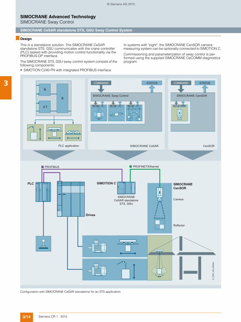
3/14 Siemens CR 1 · 2015
3
SIMOCRANE Advanced TechnologySIMOCRANE Sway Control
SIMOCRANE CeSAR standalone STS, GSU Sway Control System
■ Design
This is a standalone solution. The SIMOCRANE CeSARstandalone STS, GSU communicates with the crane controller (PLC) tasked with providing motion control functionality via the PROFIBUS-DP interface.
The SIMOCRANE STS, GSU sway control system consists of the following components:• SIMOTION C240 PN with integrated PROFIBUS interface
In systems with "sight", the SIMOCRANE CenSOR camera measuring system can be optionally connected to SIMOTION C.
Commissioning and parameterization of sway control is per-formed using the supplied SIMOCRANE CeCOMM diagnostics program.
Configuration with SIMOCRANE CeSAR standalone for an STS application
STATUSCOMMAND
PLC application
SIMOCRANE Sway Control
SIMOCRANE CeSAR
STATUSCOMMAND
SIMOCRANE CenSOR
CenSOR
G_C
R01
_EN
_003
35a
Reflector
Camera
Drives
SIMOCRANECenSOR
SIMOCRANECeSAR standalone
STS, GSU
PLC SIMOTION C
ATD ATD ATD STATCMD
PROFINET/EthernetPROFIBUS
© Siemens AG 2015

3/15Siemens CR 1 · 2015
3
SIMOCRANE Advanced TechnologySIMOCRANE Sway Control
SIMOCRANE CeSAR standalone STS, GSU Sway Control System
■ Technical specifications ■ Selection and ordering data
For the description of the operating modes, see Page 3/8.
Product designation
SIMOCRANE CeSAR standalone STS, GSUSway Control System
Type 6GA7200-1AA01-0AA0 6GA7200-1AA01-1AA0Scope of delivery • SIMOTION C240 PN • SIMOTION C240 PN
• MMC card (SW + license for opera-ting modes: MAN, POS, SNL/SND, TLS Basic)
• MMC card (SW + license for operating modes: Basic Control, SAM, TLS Advanced)
• Standard mounting rail • Standard mounting rail• License certificate • License certificate• CD-ROM with • CD-ROM with
- Documentation - Documentation- S7 project example - S7 project example
Description Article No.
Basic Control
for SIMOCRANE CeSAR standalone STS, GSU
consisting of
• SIMOTION C240 PN• MMC card
(SW + license for operating modes: MAN, POS, SNL/SND, TLS Basic)
• Standard mounting rail• License certificate• CD-ROM with documentation and S7
project example
6GA7200-1AA01-0AA0
Advanced Control
for SIMOCRANE CeSAR standalone STS, GSU
consisting of
• SIMOTION C240 PN• MMC card
(SW + license for operating modes: Basic Control, SAM, TLS Advanced)
• Standard mounting rail• License certificate• CD-ROM with documentation and S7
project example
6GA7200-1AA01-1AA0
© Siemens AG 2015

3/16 Siemens CR 1 · 2015
3
SIMOCRANE Advanced TechnologySIMOCRANE Sway Control
SIMOCRANE SC integrated OHBC, gantry crane Sway Control System
■ Design
The sway control system SIMOCRANE SC integrated OHBC, gantry crane comprises a software solution that is based on SIMOCRANE Basic Technology V3.0 and the Control Unit SIMOTION D435-2 DP/PN. Special sway-control blocks are combined with Basic Technology blocks with reference to appli-cations, see the Figure "Configuration of SIMOCRANE SC integrated for a bridge crane application".
Commissioning and parameterization of sway control is per-formed using the supplied SIMOCRANE CeCOMM
diagnostics program. The engineering software comprises the same tools as for Basic Technology, SIMOTION SCOUT and Drive Control Chart (DCC). For acquisition of the external distur-bance variables, the SIMOCRANE CenSOR camera measuring system can be optionally connected to motion controllers. Commissioning and parameterization of the camera is also per-formed using the supplied SIMOCRANE CeCOMM diagnostics program.
Configuration of SIMOCRANE SC integrated for a bridge crane application
G_C
R01
_EN
_003
46a
Reflector
Camera
SW solution intergrated in SIMOCRANE Basic Technology
SIMOCRANE CenSOR
SIMOTION D
SINAMICS
PROFINET/Industrial Ethernet
PLC
PROFIBUS/PROFINET
PLC application
STATUS
STATCMD
SIMOCRANE CenSOR
CenSOR
SIMOCRANE Basic Technology
STATUSCOMMAND
STATCMD STATCMD STATCMD STATCMD
STATCMD STATCMD STATCMD STATCMD
Application levelSIMOCRANE Sway Control
SIMOTION D
COMMAND
© Siemens AG 2015
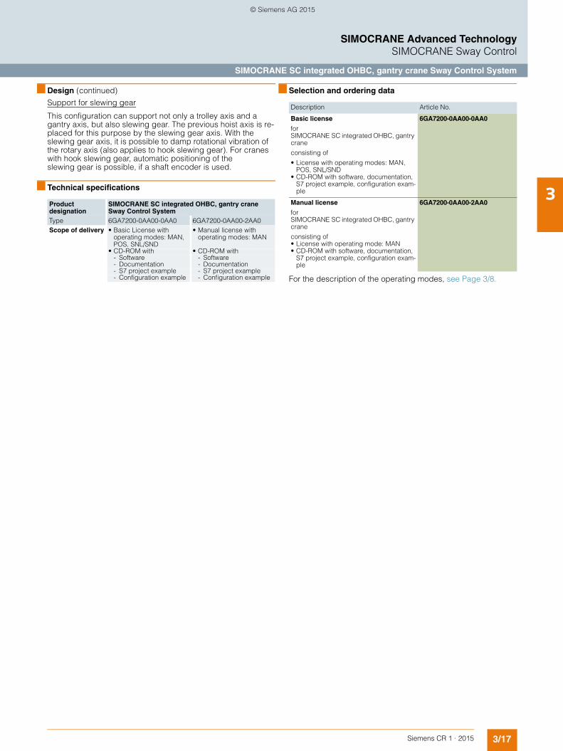
3/17Siemens CR 1 · 2015
3
■ Design (continued)
SIMOCRANE Advanced TechnologySIMOCRANE Sway Control
SIMOCRANE SC integrated OHBC, gantry crane Sway Control System
Support for slewing gear
This configuration can support not only a trolley axis and a gantry axis, but also slewing gear. The previous hoist axis is re-placed for this purpose by the slewing gear axis. With the slewing gear axis, it is possible to damp rotational vibration of the rotary axis (also applies to hook slewing gear). For cranes with hook slewing gear, automatic positioning of the slewing gear is possible, if a shaft encoder is used.
■ Technical specifications
Product designation
SIMOCRANE SC integrated OHBC, gantry craneSway Control System
Type 6GA7200-0AA00-0AA0 6GA7200-0AA00-2AA0Scope of delivery • Basic License with
operating modes: MAN, POS, SNL/SND
• Manual license with operating modes: MAN
• CD-ROM with • CD-ROM with- Software - Software- Documentation - Documentation- S7 project example - S7 project example- Configuration example - Configuration example
■ Selection and ordering data
For the description of the operating modes, see Page 3/8.
Description Article No.
Basic license
for SIMOCRANE SC integrated OHBC, gantry crane
consisting of
• License with operating modes: MAN, POS, SNL/SND
• CD-ROM with software, documentation, S7 project example, configuration exam-ple
6GA7200-0AA00-0AA0
Manual license
for SIMOCRANE SC integrated OHBC, gantry crane
consisting of• License with operating mode: MAN • CD-ROM with software, documentation,
S7 project example, configuration exam-ple
6GA7200-0AA00-2AA0
© Siemens AG 2015

3/18 Siemens CR 1 · 2015
3
SIMOCRANE Advanced TechnologySIMOCRANE Sway Control
SIMOCRANE CeSAR standalone OHBC, gantry crane Sway Control System
■ Design
The sway control system is a standalone solution. The SIMOCRANE CeSAR standalone OHBC, gantry crane commu-nicates with the crane controller (PLC) tasked with providing motion control functionality via the PROFIBUS-DP interface.
The sway control system SIMOCRANE CeSAR standalone OHBC, gantry crane consists of the following components:• SIMOTION C240 PN with integrated PROFIBUS interface
In systems with "sight", the SIMOCRANE CenSOR camera measuring system can be optionally connected to SIMOTION C.
Commissioning and parameterization of sway control is per-formed using the SIMOCRANE CeCOMM diagnostics program.
Configuration SIMOCRANE CeSAR standalone OHBC, gantry crane
PLC application
SIMOCRANE Sway Control
SIMOCRANE CeSAR
SIMOCRANE CenSOR
CenSOR
G_C
R01
_EN
_003
40a
Reflector
Camera
Drives
SIMOCRANECenSOR
SIMOCRANE CeSARStandalone OHBC,
Gantry crane
PLC SIMOTION C
PROFINET/ Industrial EthernetPROFIBUS
ATD ATD ATD STATCMD
STATUSCOMMAND STATUSCOMMAND
© Siemens AG 2015

3/19Siemens CR 1 · 2015
3
■ Design (continued)
SIMOCRANE Advanced TechnologySIMOCRANE Sway Control
SIMOCRANE CeSAR standalone OHBC, gantry crane Sway Control System
Support for slewing gear
This configuration can support not only a trolley axis and a gan-try axis, but also slewing gear. The previous hoist axis is re-placed for this purpose by the slewing gear axis. With the slew-ing gear axis, it is possible to damp rotational vibration of the rotary axis (also applies to hook slewing gear). For cranes with hook slewing gear, automatic positioning of the slewing gear is possible, if a shaft encoder is used.
■ Technical specifications
Product designation
SIMOCRANE CeSAR standalone OHBC, gantry craneSway Control System
Type 6GA7200-1AA00-0AA0 6GA7200-1AA00-2AA0Scope of delivery • SIMOTION C240 PN • SIMOTION C240 PN
• MMC card (SW + license foroperating modes: MAN, POS, SNL/SND)
• MMC card (SW + license for operating mode: MAN)
• Standard mounting rail • Standard mounting rail• License certificate • License certificate• CD-ROM with • CD-ROM with
- Documentation - Documentation- S7 project example - S7 project example
■ Selection and ordering data
For the description of the operating modes, see Page 3/8.
Description Article No.
Basic license
for SIMOCRANE CeSAR standalone OHBC, gantry crane
consisting of
• SIMOTION C240 PN• MMC card (SW + license for opera-
ting modes: MAN, POS, SNL/SND)• Standard mounting rail• License certificate• CD-ROM with software, documen-
tation and S7 project example
6GA7200-1AA00-0AA0
Manual license
for SIMOCRANE CeSAR standalone OHBC, gantry crane
consisting of
• SIMOTION C240 PN• MMC card (SW + license for opera-
ting mode: MAN)• Standard mounting rail• License certificate• CD-ROM with documentation and
S7 project example
6GA7200-1AA00-2AA0
© Siemens AG 2015

3/20 Siemens CR 1 · 2015
3
SIMOCRANE Advanced TechnologySIMOCRANE Sway Control
SIMOCRANE CenSOR camera measuring system
■ Design
SIMOCRANE CenSOR camera measuring system
Depending on the task to be performed and the environmental conditions, sway control systems can be implemented with or without camera measuring systems. If a camera is used, it has the task of observer for detecting deviations in the ideal sway re-sponse for the situation.
SIMOCRANE CenSOR is a camera measuring system which is typically deployed for cranes in order to determine the position of a marker at distances ranging from 1 to 55 m.
The standard model of the SIMOCRANE CenSOR camera measuring system consists of a camera with integrated processing unit, an integrated infrared flash (in different ver-sions) and a retroreflecting reflector whose size is determined by the maximum distance between reflector and camera.
The SIMOCRANE CenSOR camera measuring system is avail-able in two different variants:• Outdoor variant: The camera is installed in a stainless-steel
housing. This variant is suitable for outdoor applications.• Indoor variant: The camera is supplied without an enclosure
and is ideally suited to applications inside buildings. This variant is only available for the 16 mm lens with a 10 m cable.
SIMOCRANE CenSOR camera measuring system
When using a camera measuring system a reflector is also re-quired which is attached to the load suspension device.
The dimensions of the reflector are dependent on the maximum distance to be measured by the camera. The camera measuring system determines the offset of the reflector in a plane perpen-dicular to the camera axis and the rotation of the reflector.
The reflectors are specially designed to handle vibrations that typically occur on cranes and are attached to the load suspen-sion device.
The reflectors are equipped with a heating system to melt snow.
SIMOCRANE CenSOR camera measuring system for outdoor use
SIMOCRANE CenSOR Indoor camera measuring system for indoor use
Retroreflecting reflector with heater
SIMOCRANE CenSOR
CenSOR
G_C
R01
_EN
_002
43a
STATUSCOMMAND
STATCMD
© Siemens AG 2015

3/21Siemens CR 1 · 2015
3
SIMOCRANE Advanced TechnologySIMOCRANE Sway Control
SIMOCRANE CenSOR camera measuring system
■ Technical specifications
SIMOCRANE CenSOR camera measuring system
Reflector
Product designation SIMOCRANE CenSOR V2.0Type 6GA7202-1AA10-0..1 6GA7202-1AA10-1..1 6GA7202-1AA22-0BA1
Camera measuring system for SIMOCRANE Sway Control System
Camera measuring system for SIMOCRANE Sway Control System
Camera measuring system for SIMOCRANE Sway Control System
Version Outdoor Outdoor IndoorImage capture• Lens mm 16
CCD chip 1/3", 640 × 480, square pixels, full frame shutter
25 CCD chip 1/3", 1024 × 768, square pixels, full frame shutter
16CCD chip 1/3", 640 × 480, square pixels, full frame shutter
Image data transfer Triggered image capture Triggered image capture Triggered image captureInput voltage range V DC 24
+20 … -15 %DC 24 +20 … -15 %
DC 24 +20 … -15 %
Max. currentconsumption (at 24 V DC)
mA 270 (without I/O signals)
270 (without I/O signals)
270 (without I/O signals)
Switch-on current I1 Max. 2 A, < 1 ms Max. 2 A, < 1 ms Max. 2 A, < 1 msMains buffering time(at 24 V DC)
ms 10 10 10
Digital output signalsLoad current, max.(floating and short-circuit-proof)
mA 50 50 50
Short-circuit current, max. mA 240 240 240Delay times during switch ON and switch OFF
ms 0 … 2 0 … 2 0 … 2
Camera enclosure Yes, stainless-steel enclosure Yes, stainless-steel enclosure –• Supply voltage 24 V DC/10 A pulse-resistant 24 V DC/10 A pulse-resistant
Permissible ambient temperature• Ambient temperature °C -25 … +50 -25 … +50 ±0 … +50• Storage °C -30 … +70 -30 … +70 -30 … +70Dimensions• Width mm 300 300 120• Height mm 215 215 150• Depth mm 250 250 100Degree of protection IP54 IP54 IP67Weight, approx. kg 17.2
(without connection cable)17.2(without connection cable)
1(without connection cable)
Product designation SIMOCRANE CenSOR retroreflectorType 6GA7201-1AA01-0AA0 6GA7201-1AA02-0AA0Dimension W(width)
mm 300 500
Heater Yes YesReflector type Retroreflector RetroreflectorSupply voltage V 230 230Rated output W 80 500Permissible ambient temperature• Storage and transport °C -30 … +70 -30 … +70• Operation °C -25 … +70 -25 … +70Permissible relative humidity(without condensation)
% 5 ... 95 5 ... 95
Degree of protection acc. to DIN EN 60529 (IEC 60529)
IP53 IP53
Reflector dimensionsDimensions• Width mm 312 504• Height mm 312 504• Depth mm 72 78Weight, approx. kg 4.6 10.7Integration in the crane controller See Operating Manual See Operating ManualScope of delivery Reflector Reflector
© Siemens AG 2015

3/22 Siemens CR 1 · 2015
3
■ Technical specifications (continued)
SIMOCRANE Advanced TechnologySIMOCRANE Sway Control
SIMOCRANE CenSOR camera measuring system
Reflectors and lenses for SIMOCRANE CenSOR camera measuring systems
The lenses and reflector used depend on the hoisting height of the crane. For higher accuracy requirements, a lens with a larger focal length can be used. This, however, reduces the measuring range because of the smaller aperture angle.
Focal length of the lens 16 mm (standard)
25 mm
Resolution (relative to the distance)
0.12 mm/m 0.08 mm/m
Image length in the X direction(trolley)
17° 11°
Image length in the Y direction(hoist)
13° 8°
Measuring range in the X direction (relative to the distance)
292 mm/m 187 mm/m
Measuring range in the Y direction (relative to the distance)
216 mm/m 138 mm/m
Maximum hoisting height
Retroreflectors
Retroreflector 300 × 300 Up to 23 m Up to 37 m
Retroreflector 500 × 500 Up to 35 m Up to 55 m
■ Selection and ordering data
Description Article No.
SIMOCRANE CenSOR V2.0 camera measuring system
Outdoor camera for sway angle mea-surement in stainless-steel housing• with 16 mm lens (standard) and
5 m supply cable for the camera6GA7202-1AA10-0AF1
• with 16 mm lens and 15 m supply cable for the camera
6GA7202-1AA10-0BF1
• with 16 mm lens and 25 m supply cable for the camera
6GA7202-1AA10-0CF1
• with 25 mm lens and 5 m supply cable for the camera
6GA7202-1AA10-1AF1
• with 25 mm lens and 15 m supply cable for the camera
6GA7202-1AA10-1BF1
• with 25 mm lens and 25 m supply cable for the camera
6GA7202-1AA10-1CF1
SIMOCRANE CenSOR V2.0 camera measuring system
Indoor camera for sway angle mea-surement, without housing, and with 16 mm lens and 10 m cable
6GA7202-1AA22-0BA1
SIMOCRANE CenSOR retroreflector• 300 × 300 mm, with heating 6GA7201-1AA01-0AA0• 500 × 500 mm, with heating 6GA7201-1AA02-0AA0
© Siemens AG 2015
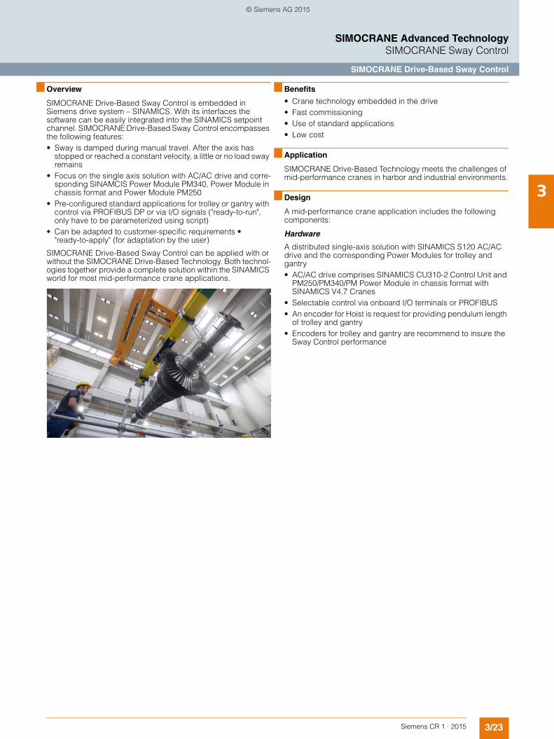
3/23Siemens CR 1 · 2015
3
SIMOCRANE Advanced TechnologySIMOCRANE Sway Control
SIMOCRANE Drive-Based Sway Control
■ Overview
SIMOCRANE Drive-Based Sway Control is embedded in Siemens drive system – SINAMICS. With its interfaces the software can be easily integrated into the SINAMICS setpoint channel. SIMOCRANE Drive-Based Sway Control encompasses the following features:• Sway is damped during manual travel. After the axis has
stopped or reached a constant velocity, a little or no load sway remains
• Focus on the single axis solution with AC/AC drive and corre-sponding SINAMCIS Power Module PM340, Power Module in chassis format and Power Module PM250
• Pre-configured standard applications for trolley or gantry with control via PROFIBUS DP or via I/O signals ("ready-to-run", only have to be parameterized using script)
• Can be adapted to customer-specific requirements • "ready-to-apply" (for adaptation by the user)
SIMOCRANE Drive-Based Sway Control can be applied with or without the SIMOCRANE Drive-Based Technology. Both technol-ogies together provide a complete solution within the SINAMICS world for most mid-performance crane applications.
■ Benefits
• Crane technology embedded in the drive• Fast commissioning• Use of standard applications• Low cost
■ Application
SIMOCRANE Drive-Based Technology meets the challenges of mid-performance cranes in harbor and industrial environments.
■ Design
A mid-performance crane application includes the following components:
Hardware
A distributed single-axis solution with SINAMICS S120 AC/AC drive and the corresponding Power Modules for trolley and gantry• AC/AC drive comprises SINAMICS CU310-2 Control Unit and
PM250/PM340/PM Power Module in chassis format with SINAMICS V4.7 Cranes
• Selectable control via onboard I/O terminals or PROFIBUS• An encoder for Hoist is request for providing pendulum length
of trolley and gantry• Encoders for trolley and gantry are recommend to insure the
Sway Control performance
© Siemens AG 2015
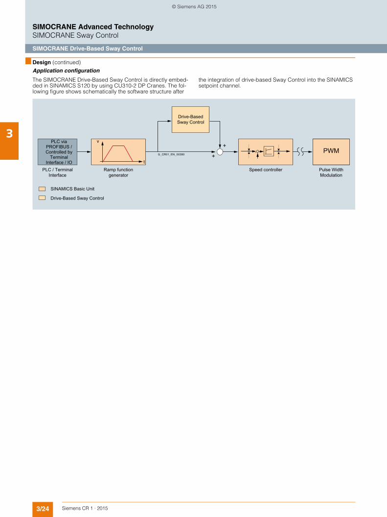
3/24 Siemens CR 1 · 2015
3
■ Design (continued)
SIMOCRANE Advanced TechnologySIMOCRANE Sway Control
SIMOCRANE Drive-Based Sway Control
Application configuration
The SIMOCRANE Drive-Based Sway Control is directly embed-ded in SINAMICS S120 by using CU310-2 DP Cranes. The fol-lowing figure shows schematically the software structure after
the integration of drive-based Sway Control into the SINAMICS setpoint channel.
Drive-BasedSway Control
Ramp function generator
SINAMICS Basic Unit
Drive-Based Sway Control
PLC via PROFIBUS / Controlled by
Terminal Interface / IO
PLC / Terminal Interface
Pulse Width Modulation
Speed controller
G_CR01_EN_00380PWM
+
+v
t
© Siemens AG 2015

3/25Siemens CR 1 · 2015
3
SIMOCRANE Advanced TechnologySIMOCRANE Sway Control
SIMOCRANE Drive-Based Sway Control
■ Technical specifications
■ Selection and ordering data
Supplementary components
Drive systems, motors and connection systems for SINAMICS S120 are not included in the package (see Chapter 6 Drive systems). These components must be ordered separately.
Additional information on selecting and ordering supplementary components is provided in the following Catalogs:• D 31 – SINAMICS and Motors for Single-axis Drives• PM 21 – SIMOTION, SINAMICS and Motors for Production
Machines• D 81.1 – Low-voltage motors, IEC squirrel-cage motors• IK PI – Industrial communication, distributed I/O, PROFIBUS
■ More information
Siemens product support
The latest information about SINAMICS products, product support and FAQs can always be found on the Internet at
https://support.industry.siemens.com/cs/→ Product Support → (Enter search term) SINAMICS
The latest information about SIMOCRANE products, product support (FAQs, Download) and application example can always be found on the Internet at
https://support.industry.siemens.com/cs/ww/de/ps/20087
Notes on licensing
The license depends on the serial number of the memory card (CompactFlash card). The crane application software cannot run without a valid license. Licensing is managed via Siemens Motion Control Web License Manager.
http://www.siemens.com/automation/license
Training
Siemens Cranes offers crane-specific training courses:
http://www.siemens.nl/training/cranes
Product designation SIMOCRANE Drive-Based Sway Control
Type 6GA7280-1AA10-0AB0Scope of delivery • CompactFlash card (CF card)
with crane-specific firmware version for SINAMICS S120 (V4.7 HF11 Cranes)
• DVD with:- STARTER installation file for
Drive-Based Sway Control- Product documentation- License certificate- Readme files- Application examples and
description
Description Article No.
SIMOCRANEDrive-Based Sway Control
includes
• CompactFlash card (CF card) with the crane-specific firmware version for SINAMICS S120 (V4.7 HF11 Cranes)
• DVD with- STARTER installation file for
Drive-Based Sway Control- Product documentation- License certificate- Readme files- Application examples and
description
6GA7280-1AA10-0AB0
Description Article No.
SINAMICS S120 Control Unit CU310-2 DP
6SL3040-1LA00-0AA0
SINAMICS Terminal Module TM31 6SL3055-0AA00-3AA1
SINAMICS STARTER V4.4 HF3 (DVD)
6SL3072-0AA00-0AG0
DCC SINAMICS V2.3
(Full lizenz)
6AU1810-1HA23-0XA0
© Siemens AG 2015
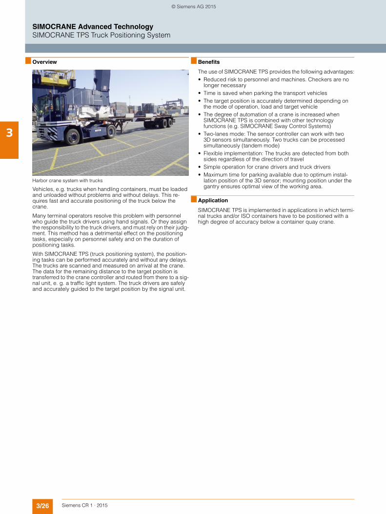
3/26 Siemens CR 1 · 2015
3
SIMOCRANE Advanced TechnologySIMOCRANE TPS Truck Positioning System
■ Overview
Harbor crane system with trucks
Vehicles, e.g. trucks when handling containers, must be loaded and unloaded without problems and without delays. This re-quires fast and accurate positioning of the truck below the crane.
Many terminal operators resolve this problem with personnel who guide the truck drivers using hand signals. Or they assign the responsibility to the truck drivers, and must rely on their judg-ment. This method has a detrimental effect on the positioning tasks, especially on personnel safety and on the duration of positioning tasks.
With SIMOCRANE TPS (truck positioning system), the position-ing tasks can be performed accurately and without any delays. The trucks are scanned and measured on arrival at the crane. The data for the remaining distance to the target position is transferred to the crane controller and routed from there to a sig-nal unit, e. g. a traffic light system. The truck drivers are safely and accurately guided to the target position by the signal unit.
■ Benefits
The use of SIMOCRANE TPS provides the following advantages:• Reduced risk to personnel and machines. Checkers are no
longer necessary• Time is saved when parking the transport vehicles• The target position is accurately determined depending on
the mode of operation, load and target vehicle• The degree of automation of a crane is increased when
SIMOCRANE TPS is combined with other technology functions (e.g. SIMOCRANE Sway Control Systems)
• Two-lanes mode: The sensor controller can work with two 3D sensors simultaneously. Two trucks can be processed simultaneously (tandem mode)
• Flexible implementation: The trucks are detected from both sides regardless of the direction of travel
• Simple operation for crane drivers and truck drivers• Maximum time for parking available due to optimum instal-
lation position of the 3D sensor; mounting position under the gantry ensures optimal view of the working area.
■ Application
SIMOCRANE TPS is implemented in applications in which termi-nal trucks and/or ISO containers have to be positioned with a high degree of accuracy below a container quay crane.
© Siemens AG 2015

3/27Siemens CR 1 · 2015
3
SIMOCRANE Advanced TechnologySIMOCRANE TPS Truck Positioning System
■ Design
Hardware
SIMOCRANE TPS consists of the following hardware compo-nents:• Sensor controller• 3D sensor
The sensor controller is based on a SIMATIC Industrial PC. The sensor controller is connected to the 3D sensor via two inter-faces:• RS422 interface for the 2D laser measurement sensor• CAN interface for the servo motor
You can connect up to two 3D sensors to a sensor controller.
The sensor controller is connected to the crane controller via Ethernet. The sensor controller is installed in a control cabinet for instance in the electrical room of the crane. It is advisable to in-stall the sensor controller as close as possible to the 3D sensors to minimize the length of supply cables.
SIMOCRANE TPS sensor controller
The 3D sensor comprises a 2D laser measurement sensor and a mechanical swiveling platform. The swiveling platform is moved by a high-precision servo motor. The data is exchanged over an RS422 connection for every 2D laser measurement sensor and over a CAN Bus connection for the servo motors.
An external RS422 interface 1) is required for the communication between the SIMOCRANE TPS 3D sensor and the SIMOCRANE TPS sensor controller. The driver of this interface adapter is al-ready installed on the SIMOCRANE TPS V1.2 sensor controller.
3D sensor
1) The interface adapter USB-2COMi SI-M is not contained in the scope of supply of SIMOCRANE TPS V1.2 sensor controller. Further Information about this adapter can be found in the SIMOCRANE TPS V1.2 operator's manual and the data sheet of the VSCOM interfaces.
© Siemens AG 2015

3/28 Siemens CR 1 · 2015
3
■ Design (continued)
SIMOCRANE Advanced TechnologySIMOCRANE TPS Truck Positioning System
The following overview graphic shows an example configuration of SIMOCRANE TPS with sensor controller and two 3D sensors:
SIMOCRANE TPS topology – crane system
SIMOCRANECMS/HMI
SIMOCRANEBasic TechnologySway Control
SIMOCRANE TPSSensor Controller
3D sensor ID1 Traffic lights Remote service
G_CR01_EN_00378
3D sensor ID0
SIMATICS7
RS422 connection
CAN bus
Firewall
Internet(VPN)
PROFIBUS DP
Industrial Ethernet
© Siemens AG 2015

3/29Siemens CR 1 · 2015
3
■ Design (continued)
SIMOCRANE Advanced TechnologySIMOCRANE TPS Truck Positioning System
Software
The SIMOCRANE TPS software consists of the following two software components:• TPS Runtime• TPS START
Both software components run on the sensor controller under the Windows operating system.
The TPS Runtime software controls the 3D sensors, evaluates the scan data and calculates the target positions for the para-meterized objects (trucks, trailers and containers). The resulting data is supplied via the OPC interface of the crane controller. In addition to this data, the interface also returns error messages and diagnostic information.
The TPS START software is the commissioning tool for SIMOCRANE TPS. As the performance capability of a system grows, so too do the requirements for its user friendliness. This is the only means of ensuring simple handling of the system. For this reason, particular attention was paid to the user friendliness of TPS START:• The system can be configured simply by means of the
parameter list.• All models are displayed almost completely in graphic form
using a 3D graphic display.• In most cases, the basic functions can be tested using an
operator panel without actual crane data.• The "Error and warnings" tab displays a clear overview of the
current system status.
SIMOCRANE TPS START
Notes:
SIMOCRANE TPS does not intervene actively in the crane's pro-cess; it simply provides information. The system must therefore be regarded as an intelligent sensor. SIMOCRANE TPS is an as-sistance system for the crane and truck driver. The crane con-troller continues to be responsible for controlling the crane, and in particular for the control of the signaling unit (e.g. traffic light, display). Signal units are not contained in the scope of supply of SIMOCRANE TPS.
A virus scan cannot be run while the TPS Runtime is running. A system virus scan would have a negative impact on system per-formance and on TPS Runtime. This means no virus scanner is available on the SIMOCRANE sensor controller. We strongly rec-ommend that you check the sensor controller for viruses at reg-ular intervals, e.g. during the maintenance of your IT, and protect your company network with a firewall.
■ Function
Container handling
3D sensors are mounted on the crane. They are controlled and evaluated by the TPS runtime software. These 3D sensors are precisely aimed at the target area.
The core of SIMOCRANE TPS is the sensor controller. This controller performs the following tasks:• Controls the 3D sensors• Collects the raw data from the scanner and detects the
scanned objects• Detects the known vehicle types• Processes logic for the operating sequences (parking
procedure)• Provides a command and data interface to the crane
controller and for operation
TPS sequence
The 3D sensors acquire vehicles to be parked in their lane when they are approximately 20 m from the target point. From this point onwards, the vehicles are identified in terms of the loaded container size(s) or the characteristics of the trailer on which the container should be placed.
Once the truck/the container trailer or the container size(s) have been identified, the distance to the target position is calculated. This depends on various factors:• Container size and spreader setting• Characteristics of the container trailer• Operating mode of SIMOCRANE TPS
The data are continuously transferred to the crane controller as a setpoint specification for positioning the vehicles.
© Siemens AG 2015

3/30 Siemens CR 1 · 2015
3
■ Function (continued)
SIMOCRANE Advanced TechnologySIMOCRANE TPS Truck Positioning System
Preparations for use
The SIMOCRANE TPS has a very simple operator interface. The crane driver switches the system on and makes the following settings:• Selects the vehicle lane• Selects the vehicle approach direction
The type of vehicle and the position of the container (front, center or rear) are determined by SIMOCRANE TPS itself.
Several factors must be considered for the use of SIMOCRANE TPS:• Dimensions of the crane• Mounting height of the 3D sensors
Assuming that the usual mounting height of the 3D sensors is 14 m above the loading point, the range of the approach route is about 20 m on both sides.
• Container trailers used
The characteristics and the dimensions of the vehicles to be detected by SIMOCRANE TPS must be entered in SIMOCRANE TPS START. The system uses the parameters to generate an object database.
Cross-section of the crane system
Typical design of a container trailer
• Number of different vehicle types
The maximum number of vehicle types that can be recognized varies in accordance with the geometric dimensions. The less the dimensions between the vehicle types vary, the fewer types (models) can be distinguished. SIMOCRANE TPS V1.2 can distinguish between a maximum of 5 models of truck and 9 models of container trailer.
• Sequence of operations under the crane
One or two 3D sensors will be required depending on the sequence of operations and the required reaction speed.
• Operational area with regard to contamination effects, weather effects and mechanical shocks
• Accessibility of 3D sensors for maintenance and service purposes (e.g. platform or stairways).
Note:
The system is based on optical sensors and is primarily affected by all effects that influence or impair the visibility of the target ob-jects.
The system can only function with known vehicles. The system will only identify vehicles which are stored as models in TPS START. The system is incapable of identifying unknown ve-hicles.
3D sensor
30000 mm
1436
0 m
m
1560
0 m
m
G_CR01_EN_00226
G_CR01_XX_00225
x
z
0
y
0x
© Siemens AG 2015

3/31Siemens CR 1 · 2015
3
SIMOCRANE Advanced TechnologySIMOCRANE TPS Truck Positioning System
■ Technical specifications
Product designation SIMOCRANE TPS V1.2Sensor controller
Type 6GA7220-1AA00-0AC0SIMATIC Embedded industrial PCGeneral technical specificationsInstallation On standard railSupply voltage DC 24 V 1 (-20 %/+20 %),
electrically isolatedShort-time voltage interruption acc. to Namur
Min. 15 ms (at 20.4 V) Max. 10 events per hour; recovery time min. 1 s
Power input, max. 64.8 W (for 24 V)Operating system Windows 7Processor Intel Core i7-3517UE 1.7 GHz, 4 MB
SLCMain store SO-DIMM Module, 4096 MB
DDR3-SDRAMHard disk 1 × 2,5" SATA-SSD, 80 GBInterfaceCAN-PCIe/402-2 • 2 × CAN (CAN 1, CAN 2)PROFINET • 3 × RJ45 connection, CP1616
compatible, onboard interface based on ERTEC 400, 10/100 MBit/s electrically isolated
USB • 4 × USB 3.0, simultaneouslyoperating of max. 2 high current
Ethernet • 2 × Ethernet interface (RJ45) Intel 82579LM and Intel 82574L
• 10/100/1000 MBit/s, electrically isolated, timing capable, 2 or 1 × Ethernet interface for equipment with PROFINET
• Connection of displays with DVI connection
Degree of protection in accordance with IEC 60529
IP20
Protection class in accordance with IEC 61140
1
Ambient temperature• Operation ±0 ... +45 ºC• Storage -40 ... +70 ºCDimensions• Width 262 mm• Height 133 mm• Depth 80.5 mmWeight, approx. 3 kg
Product designation SIMOCRANE TPS V1.23D sensor
Type 6GA7221-1AA21-0AB0General technical specificationsSupply voltage• Servo motor 48 ± 2 V DC / (Imax = 15 A)• Servo motor electronic circuits 24 ± 3 % V DC / (max. ripple 500 mV)Laser measurement sensor• Laser electronics 24 ± 3 % V DC / 2 A• Heating, laser measurement sensor
and control cabinet24 ± 6 V DC / 10 A
LMS251 laser measurement sensor• Typical range
(at 10 % remission)40 m
• Usable scanning angle 180°• Angle resolution (scanner) 0.25°, 0.5°, 1°• Measuring resolution (scanner) 13.6 mm• Wavelength of laser diode Infrared light (λ = 905 nm)• Laser/class Class 1 (safe for eyes), according to
EN/IEC 60825-1 and 21CFR1040.10• Beam divergence 11.9 mrad• Weight 3.7 kgCommunicationLMS251 laser measurement sensor RS422 (9.6/19.2/38.4/500 kbaud)
(default 500 k)Servo motor CAN (250 kbits/s)Swiveling platform• Swivel angle, max. 180° (± 90°)• Swivel angle resolution 0.008°• Swiveling velocity 100°/s (for positioning)• Weight 35 kgDegree of protection in accordance with DIN EN 60529• Laser measurement sensor IP67• Servo motor IP66 (built into a RITTAL cabinet)Shock and vibration resistance IEC 68Dimensions• Width 838 mm• Height 300 mm• Depth 340 mmAmbient temperature• Operation -30 ... +50 °C• Storage -25 ... +70 °C (max. 24 h)
SIMOCRANE TPS
Communication
OPC SIMATIC NET OPC
General technical specifations
Interface Ethernet
Application range Harbor area STS crane• Installation altitude 14 m above loading point• Transmission range 20 m (along the lane) 1)
12.5 m (along the crane travel path) 1)
• Vehicle models Trucks: max. 5
Container trailers: max. 9• Container types ISO 20 ft (6.096 m)
ISO 30 ft (9.144 m)
ISO 40 ft (12.192 m)
ISO 45 ft (13.716 m)
2 × 20 ft (2 × 6.096 m)
No. of monitoring devices• Sensor controller 1• 3D sensor Max. 2
Accuracy ± 5 cm (approximate values for a typical installation height of 14 m)
© Siemens AG 2015
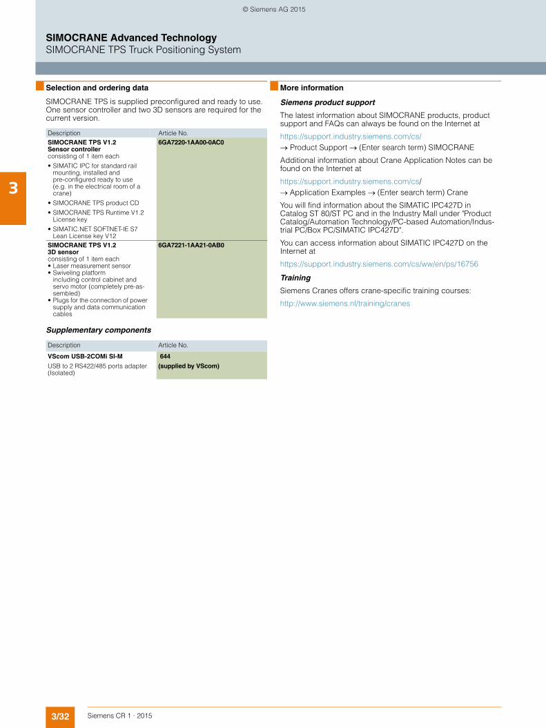
3/32 Siemens CR 1 · 2015
3
SIMOCRANE Advanced TechnologySIMOCRANE TPS Truck Positioning System
■ Selection and ordering data
SIMOCRANE TPS is supplied preconfigured and ready to use. One sensor controller and two 3D sensors are required for the current version.
Supplementary components
■ More information
Siemens product support
The latest information about SIMOCRANE products, product support and FAQs can always be found on the Internet at
https://support.industry.siemens.com/cs/→ Product Support → (Enter search term) SIMOCRANE
Additional information about Crane Application Notes can be found on the Internet at
https://support.industry.siemens.com/cs/→ Application Examples → (Enter search term) Crane
You will find information about the SIMATIC IPC427D in Catalog ST 80/ST PC and in the Industry Mall under "Product Catalog/Automation Technology/PC-based Automation/Indus-trial PC/Box PC/SIMATIC IPC427D".
You can access information about SIMATIC IPC427D on the Internet at
https://support.industry.siemens.com/cs/ww/en/ps/16756
Training
Siemens Cranes offers crane-specific training courses:
http://www.siemens.nl/training/cranes
Description Article No.SIMOCRANE TPS V1.2Sensor controllerconsisting of 1 item each
• SIMATIC IPC for standard rail mounting, installed andpre-configured ready to use (e.g. in the electrical room of a crane)
• SIMOCRANE TPS product CD
• SIMOCRANE TPS Runtime V1.2 License key
• SIMATIC.NET SOFTNET-IE S7 Lean License key V12
6GA7220-1AA00-0AC0
SIMOCRANE TPS V1.23D sensorconsisting of 1 item each• Laser measurement sensor• Swiveling platform
including control cabinet and servo motor (completely pre-as-sembled)
• Plugs for the connection of power supply and data communication cables
6GA7221-1AA21-0AB0
Description Article No.
VScom USB-2COMi SI-M
USB to 2 RS422/485 ports adapter (Isolated)
644
(supplied by VScom)
© Siemens AG 2015

Siemens CR 1 · 2015
44/2 System overview4/2 Overview4/3 Benefits4/4 Application4/4 Design
4/9 SIMOCRANE CMS Lean and CMS Basic4/9 Overview4/11 Single-user4/11 Overview4/11 Application4/12 Multi-user4/12 Overview4/13 Application4/14 Standard package4/14 Overview4/14 Function4/19 Option packages4/19 Overview4/19 Function4/26 Recommended hardware configuration4/26 Configuration4/28 SIMOCRANE CMS Lean 4/28 Technical specifications4/30 Selection and ordering data4/30 More information4/31 SIMOCRANE CMS Basic4/31 Technical specifications4/33 Selection and ordering data4/33 More information
4/34 SIMOCRANE RCMS4/34 Overview4/38 Application4/38 Design4/40 Function4/45 Recommended hardware configuration4/45 Configuration4/46 Technical specifications4/47 Selection and ordering data4/47 More information
4/48 SIMOCRANE CMS and RCMS upgrade packages
4/48 Overview4/48 Selection and ordering data
4/49 Additional components4/49 Overview4/49 Function
Security information
Siemens provides products and solutions with industrial security functions that sup-port the secure operation of plants, solutions, machines, equipment and/or networks. They are important components in a holistic industrial security concept. With this in mind, Siemens’ products and solu-tions undergo continuous development. Siemens recommends strongly that you regularly check for product updates.
For the secure operation of Siemens pro-ducts and solutions, it is necessary to take suitable preventive action (e.g. cell protec-tion concept) and integrate each compo-nent into a holistic, state-of-the-art industrial security concept. Third-party products that may be in use should also be considered. For more information about industrial security, visit http://www.siemens.com/industrialsecurity.
To stay informed about product updates as they occur, sign up for a product-specific newsletter. For more information, visit http://support.automation.siemens.com.
SIMOCRANE CMS Crane Management System
© Siemens AG 2015

4/2 Siemens CR 1 · 2015
4
SIMOCRANE Crane Management SystemSystem overview
■ Overview
SIMOCRANE CMS product overview, example of a harbor crane system
The product overview describes the implementation of SIMOCRANE CMS (Crane Management System) and its scala-bility based on the example of a harbor crane system. The appli-cation fields range from the control center/control room (Ether-net/WLAN) through loading and unloading in the harbor area right up to the maintenance station with remote access options.
1. CMS station in the electrical room of a stacking crane for maintenance technicians
2. Remote access or remote control of stacking cranes in the stacking area of a container terminal
3. CMS station in the electrical room of a ship-to-shore crane formaintenance technicians and in the cabin for the crane driver
4. Remote access to ship-to-shore cranes in the plant area(quay) of a container terminal
5. Remote access and remote control from the maintenance building for maintenance technicians and crane drivers
6. Central administration building with system administration,data archiving and evaluation
7. Remote access is possible by specialists over the Internet,remote crane access over Internet connection to CMS or RCMS
3
21
5
4
6
7
G_C
R01
_XX
_002
45
© Siemens AG 2015
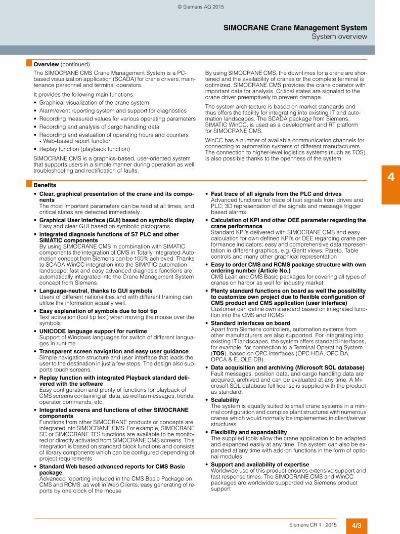
4/3Siemens CR 1 · 2015
4
■ Overview (continued)
SIMOCRANE Crane Management SystemSystem overview
The SIMOCRANE CMS Crane Management System is a PC-based visualization application (SCADA) for crane drivers, main-tenance personnel and terminal operators.
It provides the following main functions:• Graphical visualization of the crane system• Alarm/event reporting system and support for diagnostics• Recording measured values for various operating parameters• Recording and analysis of cargo handling data• Recording and evaluation of operating hours and counters
- Web-based report function• Replay function (playback function)
SIMOCRANE CMS is a graphics-based, user-oriented system that supports users in a simple manner during operation as well troubleshooting and rectification of faults.
By using SIMOCRANE CMS, the downtimes for a crane are shor-tened and the availability of cranes or the complete terminal is optimized. SIMOCRANE CMS provides the crane operator with important data for analysis. Critical states are signaled to the crane driver preemptively to prevent damage.
The system architecture is based on market standards and thus offers the facility for integrating into existing IT and auto-mation landscapes. The SCADA package from Siemens, SIMATIC WinCC, is used as a development and RT platformfor SIMOCRANE CMS.
WinCC has a number of available communication channels for connecting to automation systems of different manufacturers. The connection to higher-level logistics systems (such as TOS) is also possible thanks to the openness of the system.
■ Benefits
• Clear, graphical presentation of the crane and its compo-nentsThe most important parameters can be read at all times, and critical states are detected immediately.
• Graphical User Interface (GUI) based on symbolic display Easy and clear GUI based on symbolic pictograms
• Integrated diagnosis functions of S7 PLC and other SIMATIC componentsBy using SIMOCRANE CMS in combination with SIMATIC components the integration of CMS in Totally Integrated Auto-mation concept from Siemens can be 100% achieved. Thanks to SCADA WinCC integration into the SIMATIC automation landscape, fast and easy advanced diagnosis functions are automatically integrated into the Crane Management System concept from Siemens.
• Language-neutral, thanks to GUI symbolsUsers of different nationalities and with different training can utilize the information equally well.
• Easy explanation of symbols due to tool tip Text activation (tool tip text) when moving the mouse over the symbols
• UNICODE language support for runtimeSupport of Windows languages for switch of different langua-ges in runtime
• Transparent screen navigation and easy user guidanceSimple navigation structure and user interface that leads the user to the destination in just a few steps. The design also sup-ports touch screens.
• Replay function with integrated Playback standard deli-vered with the softwareEasy configuration and plenty of functions for playback of CMS screens containing all data, as well as messages, trends, operator commands, etc.
• Integrated screens and functions of other SIMOCRANE componentsFunctions from other SIMOCRANE products or concepts are integrated into SIMOCRANE CMS. For example, SIMOCRANE SC or SIMOCRANE TFS functions are available to be monito-red or directly activated from SIMOCRANE CMS screens. This integration is based on standard block functions and consists of library components which can be configured depending of project requirements
• Standard Web based advanced reports for CMS Basic packageAdvanced reporting included in the CMS Basic Package on CMS and RCMS, as well in Web Clients; easy generating of re-ports by one clock of the mouse
• Fast trace of all signals from the PLC and drivesAdvanced functions for trace of fast signals from drives and PLC; 3D representation of the signals and message trigger based alarms
• Calculation of KPI and other OEE parameter regarding the crane performanceStandard KPI’s delivered with SIMOCRANE CMS and easy calculation for own defined KPI’s or OEE regarding crane per-formance indicators; easy and comprehensive data represen-tation in different graphics, e.g. Gantt views, Pareto, Table controls and many other graphical representation
• Easy to order CMS and RCMS package structure with own ordering number (Article No.)CMS Lean and CMS Basic packages for covering all types of cranes on harbor as well for industry market
• Plenty standard functions on board as well the possibility to customize own project due to flexible configuration of CMS product and CMS application (user interface)Customer can define own standard based on integrated func-tion into the CMS and RCMS
• Standard interfaces on boardApart from Siemens controllers, automation systems from other manufacturers are also supported. For integrating into existing IT landscapes, the system offers standard interfaces, for example, for connection to a Terminal Operating System (TOS), based on OPC interfaces (OPC HDA, OPC DA, OPCA & E, OLE-DB).
• Data acquisition and archiving (Microsoft SQL database)Fault messages, position data, and cargo handling data are acquired, archived and can be evaluated at any time. A Mi-crosoft SQL database full license is supplied with the product as standard.
• ScalabilityThe system is equally suited to small crane systems in a mini-mal configuration and complex plant structures with numerous cranes which would normally be implemented in client/server structures.
• Flexibility and expandabilityThe supplied tools allow the crane application to be adapted and expanded easily at any time. The system can also be ex-panded at any time with add-on functions in the form of optio-nal modules.
• Support and availability of expertiseWorldwide use of this product ensures extensive support and fast response times. The SIMOCRANE CMS and WinCC packages are worldwide supporded via Siemens product support
© Siemens AG 2015
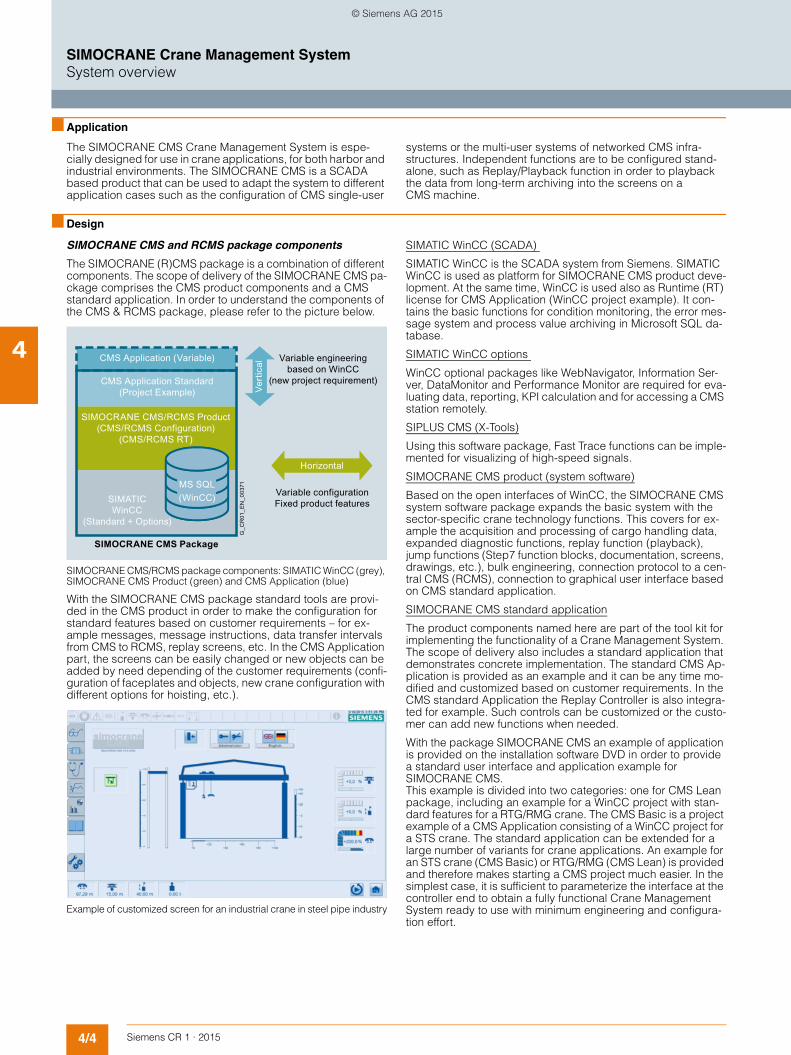
4/4 Siemens CR 1 · 2015
4
SIMOCRANE Crane Management SystemSystem overview
■ Application
The SIMOCRANE CMS Crane Management System is espe-cially designed for use in crane applications, for both harbor and industrial environments. The SIMOCRANE CMS is a SCADA based product that can be used to adapt the system to different application cases such as the configuration of CMS single-user
systems or the multi-user systems of networked CMS infra-structures. Independent functions are to be configured stand-alone, such as Replay/Playback function in order to playback the data from long-term archiving into the screens on a CMS machine.
■ Design
SIMOCRANE CMS and RCMS package components
The SIMOCRANE (R)CMS package is a combination of different components. The scope of delivery of the SIMOCRANE CMS pa-ckage comprises the CMS product components and a CMS standard application. In order to understand the components of the CMS & RCMS package, please refer to the picture below.
SIMOCRANE CMS/RCMS package components: SIMATIC WinCC (grey), SIMOCRANE CMS Product (green) and CMS Application (blue)
With the SIMOCRANE CMS package standard tools are provi-ded in the CMS product in order to make the configuration for standard features based on customer requirements – for ex-ample messages, message instructions, data transfer intervals from CMS to RCMS, replay screens, etc. In the CMS Application part, the screens can be easily changed or new objects can be added by need depending of the customer requirements (confi-guration of faceplates and objects, new crane configuration with different options for hoisting, etc.).
Example of customized screen for an industrial crane in steel pipe industry
SIMATIC WinCC (SCADA)
SIMATIC WinCC is the SCADA system from Siemens. SIMATIC WinCC is used as platform for SIMOCRANE CMS product deve-lopment. At the same time, WinCC is used also as Runtime (RT) license for CMS Application (WinCC project example). It con-tains the basic functions for condition monitoring, the error mes-sage system and process value archiving in Microsoft SQL da-tabase.
SIMATIC WinCC options
WinCC optional packages like WebNavigator, Information Ser-ver, DataMonitor and Performance Monitor are required for eva-luating data, reporting, KPI calculation and for accessing a CMS station remotely.
SIPLUS CMS (X-Tools)
Using this software package, Fast Trace functions can be imple-mented for visualizing of high-speed signals.
SIMOCRANE CMS product (system software)
Based on the open interfaces of WinCC, the SIMOCRANE CMS system software package expands the basic system with the sector-specific crane technology functions. This covers for ex-ample the acquisition and processing of cargo handling data, expanded diagnostic functions, replay function (playback), jump functions (Step7 function blocks, documentation, screens, drawings, etc.), bulk engineering, connection protocol to a cen-tral CMS (RCMS), connection to graphical user interface based on CMS standard application.
SIMOCRANE CMS standard application
The product components named here are part of the tool kit for implementing the functionality of a Crane Management System. The scope of delivery also includes a standard application that demonstrates concrete implementation. The standard CMS Ap-plication is provided as an example and it can be any time mo-dified and customized based on customer requirements. In the CMS standard Application the Replay Controller is also integra-ted for example. Such controls can be customized or the custo-mer can add new functions when needed.
With the package SIMOCRANE CMS an example of application is provided on the installation software DVD in order to provide a standard user interface and application example for SIMOCRANE CMS. This example is divided into two categories: one for CMS Lean package, including an example for a WinCC project with stan-dard features for a RTG/RMG crane. The CMS Basic is a project example of a CMS Application consisting of a WinCC project for a STS crane. The standard application can be extended for a large number of variants for crane applications. An example for an STS crane (CMS Basic) or RTG/RMG (CMS Lean) is provided and therefore makes starting a CMS project much easier. In the simplest case, it is sufficient to parameterize the interface at the controller end to obtain a fully functional Crane Management System ready to use with minimum engineering and configura-tion effort.
CMS Application (Variable)
Horizontal
G_C
R01
_EN
_003
71
Vert
ical
SIMATIC WinCC
(Standard + Options)
CMS Application Standard (Project Example)
SIMOCRANE CMS/RCMS Product (CMS/RCMS Configuration)
(CMS/RCMS RT)
Variable engineering based on WinCC
(new project requirement)
Variable configuration Fixed product features
SIMOCRANE CMS Package
MS SQL (WinCC)
© Siemens AG 2015

4/5Siemens CR 1 · 2015
4
■ Design (continued)
SIMOCRANE Crane Management SystemSystem overview
Overview of SIMOCRANE CMS/RCMS main components
Experience has shown that a number of functions always remain mostly the same in crane projects for Crane Management Sys-tems. This means that the modules can be reused in other pro-jects as well. In some cases, project dependent configurations are necessary in order to fulfill the customer requirements. Most of this requirements are related to CMS screens, which are part of the CMS standard application. The CMS system from Siemens is sufficiently open to allow the customer to fulfill these require-ments with own project engineering work.
The standard CMS application can cover the most commonly used harbor cranes (for example STS, RMG, RTG) and industrial cranes (for example ladle crane).
The CMS application is used by way of example and can be any time changed and adapted to the customer needs.
SIMOCRANE CMS package components: WinCC, CMS Application and CMS Product (green components are Cranes specific items based on own development)
Interface between PLC & Drives components and CMS
Normally the Crane Management System is connected directly to a PLC or Drive components. In case of the SIMOCRANE CMS, the channel used is an S7 channel available in WinCC for Sie-mens controllers of S7 type, S7 300 and S7 400. When S7-1500 TIA Portal is to be used, the interface should be tested and ad-apted to the customer requirements – please make enquiry for this kind of applications of our Customer Support department or Cranes Application Support (for contact data please refer to the separate section).
Standard interface between S7 and Drives and SIMOCRANE CMS
The interface is based on a defined standard based on a S7 300/400 controller. Such interface is standardized on using other SIMOCRANE based product family, such as Basic Techno-logy (BT), Drive Based Technology (DBT), Sway Control (SC), Truck Positioning System (TPS) and ECO Technology. The inter-face is provided in a separate document, where the detailed tags in WinCC and DB structure in S7 is described. This docu-ment is to be downloaded free on the customer support page from Siemens. When using the standard S7 channel from WinCC, advanced diagnostic functions can be generated and used directly in the CMS Application project with a very limited effort. This makes possible that diagnosis functions from S7 layer are to be integrated directly into the CMS level.
G_CR01_EN_00329a
Other AddOn’s
SIMOCRANE CMSPackage
CMS Standard Application
WinCC Options
&/≥
SIPLUS CMS (Fast Trace)
SIMOCRANE CMS
SIMATIC WinCC
G_CR01_EN_00373
CMS Aplication (GUI)
SIMOCRANE CMS Product
SIMOCRANE CMS Package
WinCC
S7 Drives
MS SQL (WinCC)
© Siemens AG 2015

4/6 Siemens CR 1 · 2015
4
■ Design (continued)
SIMOCRANE Crane Management SystemSystem overview
Communication CMS stations to RCMS (Remote CMS)
The communication between CMS Lean/CMS Basic stations and RCMS station(s) is based on own developed protocol included and delivered with the product SIMOCRANE CMS. For the communication between CMS and RCMS it is not neces-sary to buy a separate channel, the communication between CMS and RCMS is automatically included in each CMS station. When the customer buys a CMS Lean or CMS Basic station and later needs to connect to a RCMS (Remote CMS station), the channel is included in the packages already bought. Only the configuration needs to be done on CMS and RCMS stations in order to define the crane topology structure for CMS and RCMS (e.g. crane names, IP address of CMS, name of RCMS, IP address of RCMS, etc.)
Configuration of connection for SIMOCRANE CMS to RCMS (Remote CMS)
Overview of the configuration of SIMOCRANE CMS stations and one RCMS station
CMS App.
CMS Product
SIMOCRANE CMS Package
G_CR01_EN_00372
WinCC
RCMS App.
RCMS Product
TCP/IP
SIMOCRANE CMS Package
WinCC
CMS App.
CMS Product
SIMOCRANE CMS Package
WinCC
MS SQL (WinCC)
MS SQL (WinCC)
MS SQL (WinCC)
G_C
R01
_EN
_003
74LAN
CMS/RCMS WebClients
SIMOCRANE CMS SIMOCRANE CMS SIMOCRANE CMS
SIMOCRANE RCMS server
Remote Diagnose Mobile PC
Crane #nCrane #2Crane #1
Intranet/Internet
© Siemens AG 2015
4/7Siemens CR 1 · 2015
4
■ Design (continued)
SIMOCRANE Crane Management SystemSystem overview
Installation sites and environment
The drive and control technology and the CMS station are loca-ted in the electrical room. An industry-standard Rack PC or a Panel PC can be used as hardware platform. It is recommended that the embedded hard-ware of the new generation of Rack PC or Panel PC is used, i.e. with no moveable parts such as fan or hard drive, using a SSD card instead. In this way high availability of the hardware com-ponents can be achieved.
The user group mainly consists of service and maintenance technicians. It is possible to call up detailed diagnostic informa-tion here, by accessing documentation, circuit diagrams, S7 programmable data blocks, etc. Also the service and main-tenance personnel can perform Replay/Playback actions at CMS in the electrical room.
The CMS operator panel in the crane driver cabin is preferably a Touch PC and primarily supports the crane driver in his work.
The crane driver receives information on the fault messages, the operating states and operating data, as well as readily under-standable diagnostic information. It is only possible to set the operating mode for the crane from the crane driver cabin; and this also applies to activation and deactivation of the technologi-cal functions, such as sway control or truck positioning.
The maintenance and system technicians are based here on standby. They require remote access to the CMS systems of the cranes. This requires a standard PC which, as web client, can call up diagnostics and other information from every crane in the terminal. From maintenance building the Replay function can be activated and used on the CMS system. Remote control of cranes can also be performed from the main-tenance building as well.
In the case of a network of several cranes and a central data server for long-term archiving and consolidated evaluation, the RCMS server is located here and any further RCMS operator sta-tions with remote access to the cranes.
Administrators, the plant operator, as well as maintenance and service technicians or crane drivers with remote control desks work here. The Replay function can be used via remote station, in web environment, in order to visualize the information from the past.
From an RCMS operator station, the terminal operator has a complete overview of the crane terminal and can quickly access an individual crane without the need to be physically on the crane.
Electrical room
Crane driver cabin
Maintenance building/remote crane access
Control center/control room
© Siemens AG 2015
4/8 Siemens CR 1 · 2015
4
■ Design (continued)
SIMOCRANE Crane Management SystemSystem overview
User groups and functions
The straightforward arrangement provides this user group with the most important information about the operating state of the crane. It is important in a fault situation that the crane drivers can detect the cause as fast as possible. They must be able to de-cide quickly whether they are capable of correcting the fault themselves or whether they require support from a technician.
Apart from presenting information, they can also make operatio-nal adjustments, i.e. by activating and deactivating options such as SIMOCRANE Sway Control, SIMOCRANE Truck Positioning, etc.
This user group has specific knowledge of the system and can therefore call up more extensive diagnostic information for fast rectification of faults. Maintenance technicians must be able to access the main sources of information quickly that they require for fault rectification purposes. With regard to error messages, maintenance technicians can access specific circuit diagrams and manuals. The Replay function can also be activated and used by this user.
The terminal operator/manager is interested in statistical infor-mation and operating data. This user group is provided with this information content in the form of reports and statistics. The Re-play function can also be used in the context of remote operation of the crane from a central control desk.
The administrator has access to all authorizations and can set up and manage users. This usually comprises the personnel of the IT department of the plant operator.
Crane driver
Maintenance technician
Terminal operator/manager
Administrator
© Siemens AG 2015

4/9Siemens CR 1 · 2015
4
SIMOCRANE CMS Crane Management SystemSIMOCRANE CMS Lean and CMS Basic
■ Overview
The package SIMOCRANE CMS V4.3 includes new functions and new optional packages compared to the previous version. The new version SIMATIC WinCC V7.2, as well release for Win-dows 7 SP1 and Windows 2008 Server R2 (both 64 bit operation systems), fixing bugs from the previous versions and improve-ments regarding Standard CMS Application (provided as an example project) are to be named as important updates for CMS V4.3.
With SIMOCRANE CMS V4.3 two packages are available:• SIMOCRANE CMS V4.3 Lean package, as to be used for
crane types in harbor business, mainly for RTG, RMG, ASC and as well for industry cranes. Other types of cranes are also possible to be defined and configured via CMS Application.
Example of CMS Lean screen
• SIMOCRANE CMS V4.3 Basic package, as to be used mainly for crane types in harbor like STS and GSU. Other types of cranes are also possible to be defined and configured via CMS Application.
Example of CMS Basic screen
For both SIMOCRANE CMS V4.3 Lean and Basic packages, the CMS Application was modified and tuned for the specific crane type, the CMS Lean provided as an example for a RTG/RMG crane type and for CMS Basic provided as an example for an STS crane type.
Regarding new functions included in the SIMOCRANE CMS V4.3 Lean and Basic and RCMS V4.3 packages, please refer to the functional and delivery scope as described below.
Delivery scope SIMOCRANE CMS V4.3 Lean and Basic (Standard Package)
The SIMOCRANE CMS V4.3 Lean and Basic packages consist of different bundles and combination of WinCC Options and CMS/RCMS packages. The following bundles are delivered with standard package and options for CMS.
SIMOCRANE CMS Lean and CMS Basic V4.3• WinCC V7.2 RT licenses
- 2048 PowerTags/CMS Basic and - 512 PowerTags/CMS Lean
• WinCC 1500 Archive Tags (CMS Lean 512 Archive Tags)
• WinCC Information Server 3 WebClients (not for CMS Lean)
• SIMOCRANE CMS V4.3 Configuration• SIMOCRANE CMS V4.3 RT• Crane condition monitoring• Replay function (playback)• Message system and advanced fault diagnosis• Cargo handling acquisition• Acquisition of operating hours/counter values/timers• Advanced reporting and data aggregation
(option for CMS Lean)• Dashboards, Business Intelligence Tools
(option for CMS Lean)• Distributed information of advanced reporting via web clients
(option for CMS Lean)• Export of archived data and messages from MS SQL to Excel• Advanced S7 diagnosis• Integrated webserver for SIMOTION, SINAMICS and S7• Maintenance Instructions/Notes
(advanced message diagnosis)• Microsoft SQL (full version) with Long-Term Archiving• STEP 7 block reference
(advanced S7 diagnostics)• Jump functions to different project components
(S7 block functions, pictures, manual information, World, Excel, videos, etc.)
• Connection to RCMS
© Siemens AG 2015

4/10 Siemens CR 1 · 2015
4
■ Overview (continued)
SIMOCRANE CMS Crane Management SystemSIMOCRANE CMS Lean and CMS Basic
Options for SIMOCRANE CMS Lean package
SIMOCRANE CMS Lean + WebClients• Scope of CMS Lean Standard Package• WinCC WebNavigator: operation of one (1) or three (3) web
clients in parallel (with simultaneous connection) with monito-ring and control functions (full functionality)
SIMOCRANE CMS Lean + Central Crane DataMonitor (+ 1 WebClient)• Scope of CMS Lean Standard Package• WinCC DataMonitor: operation of one (1) web client with cen-
tral monitoring function for all cranes (read only)• Simultaneous connection to multiple cranes from one central
station – remote station • Extensive web statistical data analysis, remote connection to
Microsoft SQL database on the crane • Data aggregation from different cranes (CMS stations)• Operation of one (1) web client with full monitoring and control
functions and one (1) web client with central monitoring func-tion
SIMOCRANE CMS Lean + Crane Performance Monitor (KPI)• Scope of CMS Lean Standard Package• WinCC Performance Monitor: KPI and OEE calculations inclu-
ding advanced reporting (Gantt views, statistical data repre-sentation, data mining) on CMS and remote access of data via WebClient
Options for SIMOCRANE CMS Basic package
SIMOCRANE CMS Basic + WebClient• Scope of CMS Basic – Standard Package• WinCC WebNavigator: operation of three (3) web clients in pa-
rallel (with simultaneous connection) with monitoring and con-trol functions (full functionality)
SIMOCRANE CMS Basic + Crane Performance Monitor (KPI)• Scope of CMS Basic – Standard Package• WinCC Performance Monitor: KPI and OEE calculations inclu-
ding advanced reporting (Gantt views, statistical data repre-sentation, data mining) on CMS and remote access of data via WebClient
SIPLUS CMS Basic + Fast Trace (condition monitoring and vib-ration analysis)
This option for fast data acquisition and recording is available in combination with the previously mentioned packages.• Scope of CMS Basic – Standard Package• Fast Trace (up to 192 kHz per channel) based on SIPLUS CMS
X-Tools Software including ION's
The extended functions are not included in the standard pa-ckages. They are optional and must be ordered according to system configuration and customer applications.
© Siemens AG 2015
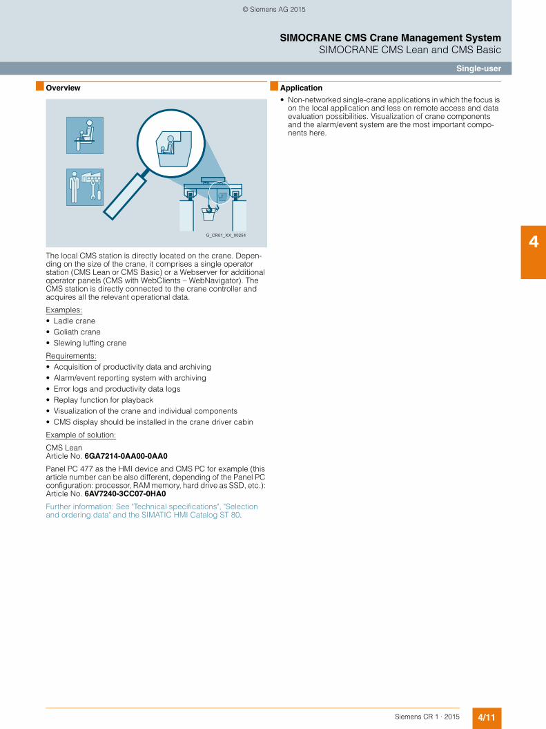
4/11Siemens CR 1 · 2015
4
SIMOCRANE CMS Crane Management SystemSIMOCRANE CMS Lean and CMS Basic
Single-user
■ Overview
The local CMS station is directly located on the crane. Depen-ding on the size of the crane, it comprises a single operator station (CMS Lean or CMS Basic) or a Webserver for additional operator panels (CMS with WebClients – WebNavigator). The CMS station is directly connected to the crane controller and acquires all the relevant operational data.
Examples:• Ladle crane• Goliath crane• Slewing luffing crane
Requirements:• Acquisition of productivity data and archiving• Alarm/event reporting system with archiving• Error logs and productivity data logs• Replay function for playback• Visualization of the crane and individual components• CMS display should be installed in the crane driver cabin
Example of solution:
CMS Lean Article No. 6GA7214-0AA00-0AA0
Panel PC 477 as the HMI device and CMS PC for example (this article number can be also different, depending of the Panel PC configuration: processor, RAM memory, hard drive as SSD, etc.): Article No. 6AV7240-3CC07-0HA0
Further information: See "Technical specifications", "Selection and ordering data" and the SIMATIC HMI Catalog ST 80.
■ Application
• Non-networked single-crane applications in which the focus is on the local application and less on remote access and data evaluation possibilities. Visualization of crane components and the alarm/event system are the most important compo-nents here.
G_CR01_XX_00254
© Siemens AG 2015
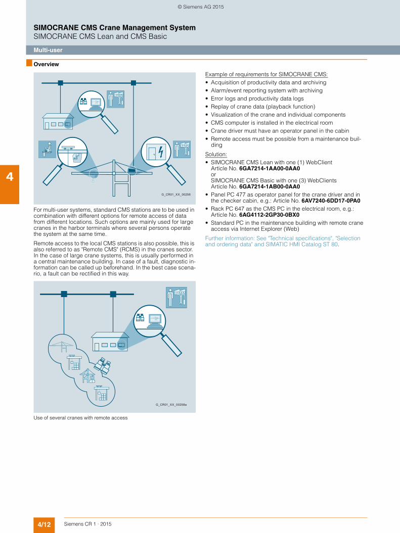
4/12 Siemens CR 1 · 2015
4
SIMOCRANE CMS Crane Management SystemSIMOCRANE CMS Lean and CMS Basic
Multi-user
■ Overview
For multi-user systems, standard CMS stations are to be used in combination with different options for remote access of data from different locations. Such options are mainly used for large cranes in the harbor terminals where several persons operate the system at the same time.
Remote access to the local CMS stations is also possible, this is also referred to as "Remote CMS" (RCMS) in the cranes sector. In the case of large crane systems, this is usually performed in a central maintenance building. In case of a fault, diagnostic in-formation can be called up beforehand. In the best case scena-rio, a fault can be rectified in this way.
Use of several cranes with remote access
Example of requirements for SIMOCRANE CMS:• Acquisition of productivity data and archiving• Alarm/event reporting system with archiving• Error logs and productivity data logs• Replay of crane data (playback function)• Visualization of the crane and individual components• CMS computer is installed in the electrical room• Crane driver must have an operator panel in the cabin• Remote access must be possible from a maintenance buil-
ding
Solution:• SIMOCRANE CMS Lean with one (1) WebClient
Article No. 6GA7214-1AA00-0AA0or SIMOCRANE CMS Basic with one (3) WebClients Article No. 6GA7214-1AB00-0AA0
• Panel PC 477 as operator panel for the crane driver and inthe checker cabin, e.g.: Article No. 6AV7240-6DD17-0PA0
• Rack PC 647 as the CMS PC in the electrical room, e.g.:Article No. 6AG4112-2GP30-0BX0
• Standard PC in the maintenance building with remote crane access via Internet Explorer (Web)
Further information: See "Technical specifications", "Selection and ordering data" and SIMATIC HMI Catalog ST 80.
G_CR01_XX_00256
G_CR01_XX_00258a
© Siemens AG 2015
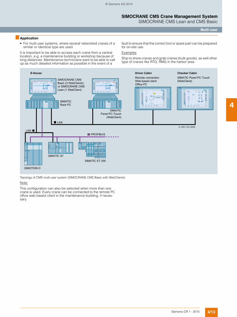
4/13Siemens CR 1 · 2015
4
SIMOCRANE CMS Crane Management SystemSIMOCRANE CMS Lean and CMS Basic
Multi-user
■ Application
• For multi-user systems, where several networked cranes of a similar or identical type are used.
It is important to be able to access each crane from a central location, e.g. a maintenance building or workshop because of long distances. Maintenance technicians want to be able to call up as much detailed information as possible in the event of a
fault to ensure that the correct tool or spare part can be prepared for on-site use.
Examples
Ship to shore cranes and grab cranes (bulk goods), as well other type of cranes like RTG, RMG in the harbor area
Topology of CMS multi-user system (SIMOCRANE CMS Basic with WebClients)
Note:
This configuration can also be selected when more than one crane is used. Every crane can be connected to the remote PC office web based client in the maintenance building, if neces-sary.
Checker CabinDriver CabinE-House
G_CR01_EN_00359
SIMATIC Panel PC-Touch
(WebClient)
SIMATIC Rack PC
SIMATIC Panel PC-Touch(WebClient)SIMOCRANE CMS
Basic (3 WebClients) or SIMOCRANE CMS Lean (1 WebClient)
Remote connection Web-based client Office PC
LAN
SIMATIC ET 200
SIMATIC S7
SIMOTION D
LAN
PROFIBUS
© Siemens AG 2015

4/14 Siemens CR 1 · 2015
4
SIMOCRANE CMS Crane Management SystemSIMOCRANE CMS Lean and CMS Basic
Standard package
■ Overview
The standard package of SIMOCRANE CMS Lean and CMS Basic consists of functions which are standard delivered with the package. By ordering the standard package, basic functions are to be realized for CMS Lean and CMS Basic in or-der to respond to the main requirements for Crane Management System on the crane market. In the next section the main func-tions are briefly described.
■ Function
Status display
The status display offers a symbol-oriented, graphical display of the crane and crane components complete with the current ope-rating values and statuses. It is a very useful tool for the crane driver. Important displays are always in view, and detailed views can be called up in just a few steps. Although the interface is based on icons, moving the mouse over the elements in the screen detailed information and text can be visualized in order to receive information about the used symbols.
The status display screen provides supplementary information which will help the crane driver in his work. He is then capable of recognizing the cause of simple faults, such as interlocking for certain movements.
A status bar at the top of the screen displays fault states symbo-lically, and this is supplemented by text messages at the bottom of the screen.
Graphical status display for the spreader
Replay function (playback)
The replay function is delivered in the standard basic package of SIMOCRANE CMS. This function enables the personal to visu-alize (playback) the data in the screens from the past recorded in the database (similar to a DVD player). Thanks to a replay con-troller the operator can set different parameters and navigate through the screens, for example: set time span for replayed data, use navigation buttons (play, stop, pause, back-forward, speed, etc.), navigate through different replayed screens. The screens for the replay/payback function can be freely configura-ble via Relay Configuration Editor.
Example of replay home screen for an STS crane
© Siemens AG 2015

4/15Siemens CR 1 · 2015
4
■ Function (continued)
SIMOCRANE CMS Crane Management SystemSIMOCRANE CMS Lean and CMS Basic
Standard package
Example of replay screen for hoist screen of STS crane
Example of replay screen for an RTG crane
The screens for the replay/playback function can be freely con-figurable via Replay Configuration Editor. The Replay Configura-tion Editor is integrated into SIMOCRANE CMS product Configu-ration Editor. This enables the configuration of replay screens for the replay function in runtime visualization. The replay function is working complete independent from CMS RT function, which is collecting the data continuously from field. The replay function is working in parallel with CMS RT data acquisition and can be switched on or off via graphical user interface any time the ope-rator needs performing replay.
Replay Configuration Editor for replay screen configuration
With the Replay Configuration Editor, you can make the following settings required for Replay:• Maximum number of archive tags; see the SIMOCRANE CMS
operating instructions.• Select the pictures to be prepared for Replay• Check one or more pictures prepared for Replay• Repair pictures prepared for Replay• Clean up tags that are no longer needed• Deselect pictures• You can expand and view the list of Picture Selector Tags
(read only)
The Replay Configuration Editor checks whether the require-ments for Replay have been met every time a picture is selected or repaired. The necessary tags and structures are checked for completeness.
The following are required for Replay:• ReplayControl structure• Tags of the group ReplayControl with ReplayControl structure
tags• Tags of the Screens group that are relevant for Replay• Tags of the Settings group that are relevant for Replay• Tags of the ReplayControl group that are relevant for Replay• Picture selector tags• ReplayArchive
Replay Configuration Editor – replay screen automatic generation of modules by screen changes in WinCC project
© Siemens AG 2015

4/16 Siemens CR 1 · 2015
4
■ Function (continued)
SIMOCRANE CMS Crane Management SystemSIMOCRANE CMS Lean and CMS Basic
Standard package
Error messages and advanced diagnostics
In the event of a fault, the error message system helps with trou-bleshooting and fault rectification. These complex functions sup-port maintenance technicians with their work and help to reduce downtime.Detailed error lists present the course of the fault chro-nologically. Many filtering and sorting functions increase clarity.
Comprehensive message system
Example of screen for maintenance instruction function Chronological message bar – message instructions
When an error message is selected, further sources of informa-tion can be accessed, such as:• Maintenance instructions and notes • Circuit diagrams Manuals, operating manuals, data sheets • Screens, drawings Failure diagnosis• Jump to different Microsoft programs, as Excel, PPT, World,
etc. • Jump to videos related to the message content• Direct navigation and jump to the PLC program and block
functions related to the fault message content
Jump functions to different CMS program content – in this example jump to manuals
Jump functions to different CMS program content – in this example jump to S7 program block functions
Apart from the chronological message list, there are also statis-tical views that provide information on the frequency and dura-tion of faults (hit list).
These make it easy to identify weak points and to obtain informa-tion about downtimes.
Example of statistical analysis (hit list) for messages
© Siemens AG 2015

4/17Siemens CR 1 · 2015
4
■ Function (continued)
SIMOCRANE CMS Crane Management SystemSIMOCRANE CMS Lean and CMS Basic
Standard package
Measured value acquisition
CMS continuously acquires and archives important parameters, such as• Position values of different components of the crane – hoist,
trolley, gentry, etc.• Setpoint inputs and actual values• Speed, velocity, etc.
These values can be displayed in the form of trend curves at any time, and easily configured in RT configuration editors, with no necessary know-how of engineering or complex programs.
Crane parameter value acquisition – extended configuration in RT envi-ronment
Cargo handling
The cargo handling data of a crane is acquired and archived in order of occurrence. The composition of the data fields (cargo handling data set) is freely configurable and can therefore be adapted for every crane type.
An overview can be called up in the form of a list at any time at the press of a button.
Cargo handling data
Container handling list
The archived data can be made available to higher-level sys-tems for further evaluation.
MMBF – Mean Moves Between Failures
MMBF (cargo handling moves between failures) is one of the most important key performance indicators in crane technology. It provides information on the availability of the crane.
Runtime meter
Maintenance planning systems require counts from runtime me-ters and counters for the components with relevance to mainte-nance. These values are originally acquired by the crane cont-roller. The CMS acquires these values from the controller and makes them available to higher-level systems.
Screen with Move Data of containers Operating hour counter
It is possible to acquire operating hours and counter values and process them.
These values can be initialized or backed up in the controller via the CMS user interface. This function is extremely helpful if the CPU in the PLC has to be replaced.
© Siemens AG 2015

4/18 Siemens CR 1 · 2015
4
■ Function (continued)
SIMOCRANE CMS Crane Management SystemSIMOCRANE CMS Lean and CMS Basic
Standard package
Reporting lists
A simple form of report output is integrated into the system. The following reports can be output on the standard Windows prin-ter:• Current or archived fault reports• Report of cargo handling data • MMBF report
The tools that are available with WinCC allow the reports inclu-ded as standard to be adapted or expanded at any time, and you can create and design your own reports.
This report in PDF format can easily be output on a PDF printer.
Advanced reporting
On each CMS station advanced reporting generation can be processed. This report is based on integration of different infor-mation regarding messages, operational data (e.g. move data, MMBF, counters, timers), statistics, data mining. The access is possible direct from Microsoft SQL database. The report is web based and can be pre-configured for standard data sets. Each report can be customized in order to fulfill the customer require-ments.• Advanced Reporting from CMS and RCMS stations possible
on every mobile device.• Being informed anytime – from everywhere: web-based re-
ports and analyses using mobile devices• Reporting and management using Microsoft SQL Server
Reporting Services• Transparent access to all historical CMS and RCMS data in
Microsoft SQL database• Cyclic activation based on demands or events• Web-based administration and provision• Transparent data access thanks to integration in MS Word,
MS Excel and MS PowerPoint• Automatic report distribution by email• Customized dashboards and Business Intelligence tools on
board
Advanced reporting of crane data using information server
© Siemens AG 2015

4/19Siemens CR 1 · 2015
4
SIMOCRANE CMS Crane Management SystemSIMOCRANE CMS Lean and CMS Basic
Option packages
■ Overview
Additional functions can be offered via optional packages of SIMOCRANE CMS. These functions can be taken in project de-pending of customer requirements. In this manner, SIMOCRANE CMS offers maximum flexibility for adding extra functions to the standard package. In the next section a brief overview of optio-nal packages of SIMOCRANE CMS is presented. In order to offer
additional functionality together with the SIMOCRANE CMS pa-ckage, the combination between CMS and other Add-ons from SIMATIC family can be offered by using Add-ons. For more information please refer to the Chapter Additional com-ponents.
■ Function
Crane down time monitoring (crane availability and Gantt views)
On each CMS the KPI‘s or crane availability can be visualized thanks to the WinCC option package Performance Monitor. The calculation of KPI’s or data representation for CMS is automati-cally integrated into the project. Pre-defined reports and data re-presentation can any time recalled in order to generate advan-ced reports fast and easy. Data representation is very easy and the option package Performance Monitor has several very useful functions standard on board.
Example of screen in CMS for Crane Performance Monitor – crane availability and Gantt view graph
Example of screen in CMS for Crane Performance Monitor – reporting of data (number of loads)
In order to access MS SQL data and retrieve data at one click of the mouse, a tool in Microsoft Excel was developed. The Excel tool can be installed on any office PC in the terminal. The only prerequisite to access the MS SQL data from archive on CMS & RCMS stations is to have connection to the CMS & RCMS PC. This can be checked via integrated Topology Configuration Menu, where the CMS & RCMS stations, with PC name and IP address are to be defined.
Using the Excel data access tool, all alarms and archive tags form achieves in CMS and RCMS stations can be retrieved and visualized in the Excel sheet integrated into the delivered tool. Statistics of alarms and information from operational data, such as moves, MMFB, counters, timers, etc. can be easy visualized and saved in the Excel data sheet. The Excel tool is an applica-tive solution, delivered standard with CMS Application and free of charge with the SIMOCRANE CMS and RCMS product.
© Siemens AG 2015

4/20 Siemens CR 1 · 2015
4
■ Function (continued)
SIMOCRANE CMS Crane Management SystemSIMOCRANE CMS Lean and CMS Basic
Option packages
Easy access of data from CMS and RCMS stations via Microsoft Excel
Example of screen in Excel for alarms analysis from SIMOCRANE CMS station
Example of screen in Excel for tag logging data analysis from SIMOCRANE CMS station; browsing of all archive data in Microsoft SQL database on CMS/WinCC station
G_CR01_EN_00366
LAN
No installation of CMS/RCMS software required, only MS Excel needed
Microsoft SQL
SIMOCRANE CMS Lean or SIMOCRANE CMS Basic
SIMOCRANE CMS Lean or SIMOCRANE CMS Basic
SIMOCRANE CMS Lean or SIMOCRANE CMS Basic
SIMOCRANE RCMS
Crane #nCrane #2Crane #1
MS Excel 2010
© Siemens AG 2015

4/21Siemens CR 1 · 2015
4
■ Function (continued)
SIMOCRANE CMS Crane Management SystemSIMOCRANE CMS Lean and CMS Basic
Option packages
Multi-user system for CMS Lean and CMS Basic – WebClients
Using the optional package WinCC WebNavigator, the CMS sta-tion can be expanded with additional operator stations. A typical application is an operator panel in the crane driver cabin or at another location in the crane.
Access is, however, also possible from the outside provided that the CMS station on the crane is accessible over the network or the Internet.
The access rights can be individually configured for each ope-rator station and each user.
WinCC WebNavigator is provided as option for the CMS Basic and CMS Lean packages.
Example of screen of a WebClient with WebNavigator
The number of WebClients offered standard are with the CMS Basic are three and for CMS Lean are two possibilities to order the WebClients: (1) with one WebClient or (2) with three WebCli-ents. In case in the terminal more WebClients are needed for the local CMS, additional clients can be ordered separately.
Further information: See "Technical specifications", "Selection and ordering data" and SIMATIC HMI Catalog ST 80.
© Siemens AG 2015

4/22 Siemens CR 1 · 2015
4
■ Function (continued)
SIMOCRANE CMS Crane Management SystemSIMOCRANE CMS Lean and CMS Basic
Option packages
CMS Lean – Crane Central DataMonitor
On the CMS Lean package, the Crane DataMonitor concept is using a DataMonitor license only for one DataMonitor Client. This client is connected to all other local CMS stations, which are in-stalled on the crane. The connection form each crane is done via encrypted connection from the DataMonitor webserver and the clients. The advantage of this configuration is that with a simple and cost effective solution different configurations can be provi-ded for industry crane applications as well as for harbor area. When needed, the number of DataMonitor clients can be exten-ded with additional licenses on the DataMonitor webserver.
With CMS DataMonitor a project already configured using DataMonitor is delivered with the standard CMS Application.
The optional package DataMonitor offers user-friendly functions for the graphical evaluation of cargo handling data, number of faults and other operating data of the crane. You can use a web-based user interface to create your own evaluations or adapt existing ones at any time.
These evaluations are possible directly on the CMS station or from a generally available office PC, which, however, must be connected to each CMS on the crane over the network.
Overview of CMS Central Crane DataMonitor
Remote Diagnose/Mobile PC Tablet PC
G_CR01_EN_00368
Crane #nCrane #2Crane #1
Remote Office PC Central Crane Data Monitoring
Intranet/Internet
Export of data (Excel)
Data mining and data representation (archive tags, tags, alarms)
Excel plug-insAdvanced reportingRemote access of screens (read only)
SIMOCRANE CMS Lean SIMOCRANE CMS Lean SIMOCRANE CMS Lean
LAN
© Siemens AG 2015

4/23Siemens CR 1 · 2015
4
■ Function (continued)
SIMOCRANE CMS Crane Management SystemSIMOCRANE CMS Lean and CMS Basic
Option packages
Data Aggregation using CMS Central Crane DataMonitor
Graphical data representation in DataMonitor
In addition to data evaluation, the DataMonitor can also be used for remote access to the local cranes and CMS user interface. In this case, however, it is purely a monitoring mode. For most ap-plications, this is adequate as a remote access function. The op-tion package CMS WebNavigator for remote access purposes is not necessary in this case.
CMS Lean and CMS Basic Crane Performance Monitor
For CMS Lean and CMS Basic packages the optional package from WinCC Performance Monitor can be used in order to cal-culate KPI’s or perform crane availability for each crane. The WinCC Performance Monitor is delivered as optional package for CMS Lean and CMS Basic as separate article number – ple-ase refer to section for CMS Lean and CMS Basic ordering data.
When Crane Performance Monitor option is activated via the license, the screens predefined in the CMS Application can be activated via the settings menu in the CMS Application (WinCC project). The screens are predefined for standard reports on the CMS, showing information about crane status, number of loads, weight of loads, consumed energy, etc.
The calculation of KPI’s for each crane can be modified depen-ding of the project requirements. Own reports generated in run-time on the CMS station can be realised. The information of the Crane Performance Monitor can be visualized remote as well via WebNavigator using WebClients. In order to choose the right ar-ticle number please refer to the ordering number structure of CMS Lean and CMS Basic packages.
Example of screen for CMS Crane Performance Monitor option
© Siemens AG 2015
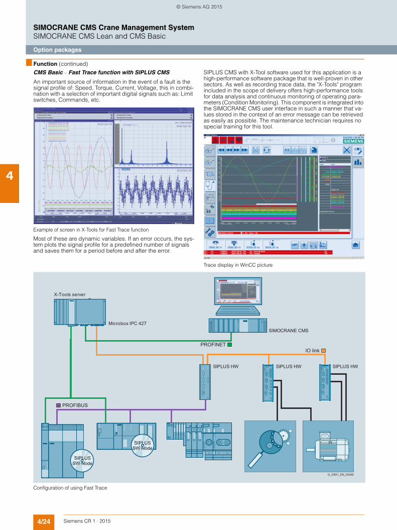
4/24 Siemens CR 1 · 2015
4
■ Function (continued)
SIMOCRANE CMS Crane Management SystemSIMOCRANE CMS Lean and CMS Basic
Option packages
CMS Basic – Fast Trace function with SIPLUS CMS
An important source of information in the event of a fault is the signal profile of: Speed, Torque, Current, Voltage, this in combi-nation with a selection of important digital signals such as: Limit switches, Commands, etc.
Example of screen in X-Tools for Fast Trace function
Most of these are dynamic variables. If an error occurs, the sys-tem plots the signal profile for a predefined number of signals and saves them for a period before and after the error.
SIPLUS CMS with X-Tool software used for this application is a high-performance software package that is well-proven in other sectors. As well as recording trace data, the "X-Tools" program included in the scope of delivery offers high-performance tools for data analysis and continuous monitoring of operating para-meters (Condition Monitoring). This component is integrated into the SIMOCRANE CMS user interface in such a manner that va-lues stored in the context of an error message can be retrieved as easily as possible. The maintenance technician requires no special training for this tool.
Trace display in WinCC picture
Configuration of using Fast Trace
IO link
SIPLUS HW
G_CR01_EN_00369
SIPLUS HWSIPLUS HW
Microbox IPC 427
X-Tools server
SIMOCRANE CMS
SIPLUS SW Node
SIPLUS SW Node
PROFINET
PROFIBUS
© Siemens AG 2015

4/25Siemens CR 1 · 2015
4
■ Function (continued)
SIMOCRANE CMS Crane Management SystemSIMOCRANE CMS Lean and CMS Basic
Option packages
IONs – Input-Output Nodes
SIPLUS CMS offers "IONs" for acquiring measured values. These are hardware or software modules that acquire the mea-sured values. The software nodes, ION’s are included in the standard software X-Tools when this option is ordered. The hard-ware for ION’s should be ordered separately, it is not part of the optional package in CMS Basic. Such hardware depends of the project configuration.
With the numerous hardware IONs in the SIPLUS product range, measured values can be acquired directly where they arise. This avoids incorrect interpretations which may result due to the time taken to transmit via a controller. Sampling rates of up to 40 kHz (analog) or 50 kHz (binary) are possible using hardware IONs.
Software IONs
SIPLUS CMS records the data directly from the SIMATIC S7 and SIMOTION controllers using appropriate software IONs (Input-Output Nodes). The sampling rate using software IONs depends on the controller platform used. A "cycle-synchronized" trace can thus be achieved.
PROFIBUS ION
The PROFIBUS ION, also known as "Spy", is particularly versa-tile. This module can be used to record any values which pass via the PROFIBUS. The spy is a totally passive node and affects neither the bus nor the cycle time of controllers. The sampling rate that can be achieved is the PROFIBUS cycle. The PROFIBUS ION should be ordered separately.
Selection criteria software ION characteristics:• For an integrated SIMATIC S7 or SIMOTION complete solution• Up to 172 channels (signals or values) per controller• Sampling rate up to the minimum cycle time of the controller
(depending on the quantity structure)• No additional hardware components required• Communication via existing Ethernet interfaces
PROFIBUS ION (PROFIBUS Spy) characteristics:• Independent of the controller used• Expansion capability regarding the number of signals• Sampling rate in the PROFIBUS cycle• No resources required on the controller side
(cycle time, memory)• Communication over IEEE (interface required in the PC)
© Siemens AG 2015

4/26 Siemens CR 1 · 2015
4
SIMOCRANE CMS Crane Management SystemSIMOCRANE CMS Lean and CMS Basic
Recommended hardware configuration
■ Configuration
Hardware configurations from the SIMATIC IPC and SIMATIC Panel PC range are recommended for SIMOCRANE CMS Lean and CMS Basic software packages. In accordance with the re-commendations, alternative computer hardware can also be used.
Please enquiry in order to check the chosen hardware configu-ration in combination with CMS software components.
Recommended hardware configurations for CMS
SIMOCRANE CMS Lean or CMS Basic station on the crane (standard package/single-user station)SIMATIC Touch PC version e.g. SIMATIC Panel PC 677
Used as operator panel in the crane driver cabin
Suitable for 5 g shock load
Alternative solutions: SIMATIC Panel PC 477, SIMATIC IPC 427 Microbox Embedded hardware (no fan, no other movable parts)
Front panel Touch 15" or greaterProcessor Core i3, or better performance
(recommended i5)Memory configuration Minimum 4 GB
(recommended 8 GB)Hard drive RAID1, 2 × 500 GB, or moreOptical drives DVD±RCommunications interfaces EthernetOther interfaces USBOperating system Windows 7 SP1 (64 bit)
SIMOCRANE CMS Lean or CMS Basic station on the crane (single-user or multi-user station)SIMATIC Rack PC versione.g. SIMATIC Rack PC 647
Suitable for 5 g shock load
Additionally, monitor min. 1280 × 1024 dpi or widescreen format
Alternative solutions: SIMATIC Panel PC 477, SIMATIC IPC427 Microbox Embedded hardware (no fan, no other movable parts)
Processor Core i5, or better performance Memory configuration Minimum 4 GB
(recommended 8 GB)Hard drive RAID1, 2 × 500 GB, or moreOptical drives DVD±RCommunications interfaces 2 × Ethernet (PROFIBUS)Other interfaces USBOperating system Windows 7 SP1 (64 bit)
SIMOCRANE CMS Lean or CMS Basic operator panel on the craneWebClient for the CMS computer
SIMATIC Touch PC version e.g. SIMATIC Panel PC 477
Used as operator panel in the crane driver cabin or checker cabin
Suitable for 5 g shock load
Preferably diskless
Front panel Touch 15" or greaterProcessor Core i3, or better performance Memory configuration Minimum 4 GB
(recommended 8GB)Mass storage SSD 50 Gb/80 Gb or more
(Solid State Card)Communications interfaces Ethernet (PROFIBUS)Other interfaces USBOperating system Windows 7 SP1 (32 bit/64 bit)
© Siemens AG 2015
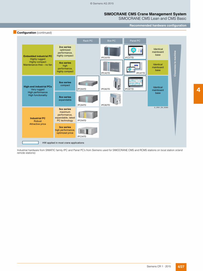
4/27Siemens CR 1 · 2015
4
■ Configuration (continued)
SIMOCRANE CMS Crane Management SystemSIMOCRANE CMS Lean and CMS Basic
Recommended hardware configuration
Industrial hardware from SIMATIC family IPC and Panel PC’s from Siemens used for SIMOCRANE CMS and RCMS stations on local station or/and remote stations)
Rack PC
HW applied in most crane applications
Box PC Panel PC
Clo
sene
ss to
mac
hine
G_CR01_EN_00365
Identical mainboard
base
2xx series optimized
performance, highly compactEmbedded industrial PC
Highly rugged Highly compact
Maintenance-free – no fan
High-end industrial PCs Very rugged
High performance High functionality
Industrial PC Robust
Attractive price
6xx series compact
8xx series expandable
4xx series high
performance, highly compact
5xx series maximum
performance, expandable, latest
PC technology
3xx series high performance,
optimized price
Identical mainboard
base
Identical mainboard
base
IPC277DIPC227D
IPC427D
IPC627D
IPC827D
IPC647D
IPC847D
IPC547D
IPC347D
IPC477D
IPC677D
© Siemens AG 2015

4/28 Siemens CR 1 · 2015
4
SIMOCRANE CMS Crane Management SystemSIMOCRANE CMS Lean and CMS Basic
SIMOCRANE CMS Lean
■ Technical specifications
Ordering packages SIMOCRANE CMS Lean
Standard(Single-User)
Standard + WebClients (Multi-User)1 WebClient3 WebClients
Standard +Crane Central Data Monitor +WebClients
Standard +Crane Performance Monitor +WebClients
Type 6GA7214-0AA00-0AA0 6GA7214-1.A00-0AA06GA7214-2.A00-0AA0
6GA7214-3.A00-0AA06GA7214-4.A00-0AA0
6GA7214-1.A00-1AA06GA7214-4.A00-0AA0
Configurable presentation• Crane types
- RMG/RTG 1) - Industrial cranes (e.g. ladle crane)
• Drives - Hoist - Gantry - Trolley - Slewing gear 2)
• Load suspension device - Grab 2) - Hook 2) - Single, twin, tandem spreader - Gripping tongs 2)
• Add-on modules - Sway Control settings - Truck Positioning settings 2)
Condition monitoring• Crane components
- Crane overview - Boom - ry drives - Spreader
• Positions • Limit switches • Weight • Drives
- Setpoint/actual values - Brakes
• Rope drums - Safety brakes
• Wind - Rail clamps - Interlock bolts
• Interlocks - Operation-specific - Emergency OFF - Access (doors)
• Main power supply
Operator functions• Counter handling • Sway Control modes 2) • Truck Positioning modes 2)
Error diagnostics• Approx. 100 typical, preconfigured crane error
messages 3)
• Display of pending and historical messages • Statistical message overview ("hit list") • Symbolic error status display • Graphical assignment in the status display • Call-up of supplementary information
- Documents (examples only) - Screens (examples only) - Circuit diagrams (examples only)
• STEP 7 network and function blocks entry point (symbolic or absolute)
• Process values to accompany messages (e.g. positions)
• SIMATIC S7 WebServer (CPU diagnostics; CPU-dependent)
• SIMOTION WebServer integration (version dependent)
For legends and footnotes, see Page 4/29.
© Siemens AG 2015
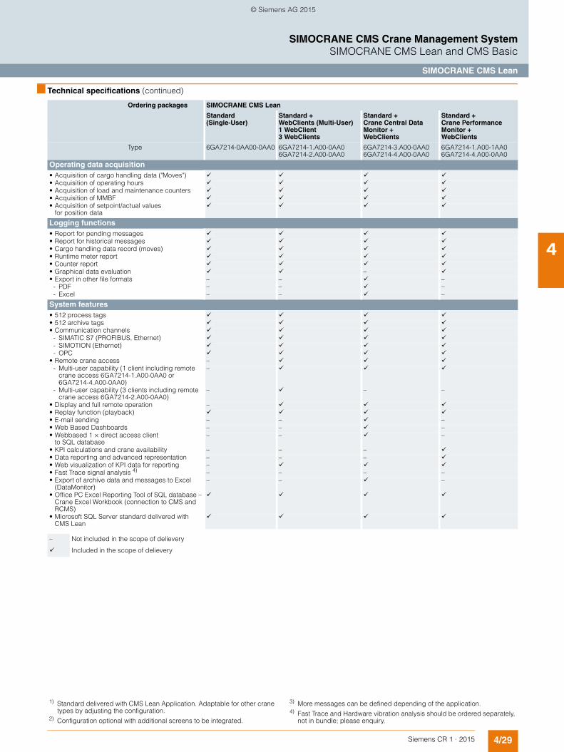
4/29Siemens CR 1 · 2015
4
■ Technical specifications (continued)
SIMOCRANE CMS Crane Management SystemSIMOCRANE CMS Lean and CMS Basic
SIMOCRANE CMS Lean
Operating data acquisition• Acquisition of cargo handling data ("Moves") • Acquisition of operating hours • Acquisition of load and maintenance counters • Acquisition of MMBF • Acquisition of setpoint/actual values
for position data
Logging functions• Report for pending messages • Report for historical messages • Cargo handling data record (moves) • Runtime meter report • Counter report • Graphical data evaluation – • Export in other file formats – – –
- PDF – – –- Excel – – –
System features• 512 process tags • 512 archive tags • Communication channels
- SIMATIC S7 (PROFIBUS, Ethernet) - SIMOTION (Ethernet) - OPC
• Remote crane access – - Multi-user capability (1 client including remote
crane access 6GA7214-1.A00-0AA0 or6GA7214-4.A00-0AA0)
–
- Multi-user capability (3 clients including remote crane access 6GA7214-2.A00-0AA0)
– – –
• Display and full remote operation – • Replay function (playback) • E-mail sending – – –• Web Based Dashboards – – –• Webbased 1 × direct access client
to SQL database– – –
• KPI calculations and crane availability – – – • Data reporting and advanced representation – – – • Web visualization of KPI data for reporting – • Fast Trace signal analysis 4) – – – –• Export of archive data and messages to Excel
(DataMonitor)– – –
• Office PC Excel Reporting Tool of SQL database – Crane Excel Workbook (connection to CMS and RCMS)
• Microsoft SQL Server standard delivered with CMS Lean
Ordering packages SIMOCRANE CMS Lean
Standard(Single-User)
Standard + WebClients (Multi-User)1 WebClient3 WebClients
Standard +Crane Central Data Monitor +WebClients
Standard +Crane Performance Monitor +WebClients
Type 6GA7214-0AA00-0AA0 6GA7214-1.A00-0AA06GA7214-2.A00-0AA0
6GA7214-3.A00-0AA06GA7214-4.A00-0AA0
6GA7214-1.A00-1AA06GA7214-4.A00-0AA0
– Not included in the scope of delievery
Included in the scope of delievery
1) Standard delivered with CMS Lean Application. Adaptable for other crane types by adjusting the configuration.
2) Configuration optional with additional screens to be integrated.
3) More messages can be defined depending of the application.4) Fast Trace and Hardware vibration analysis should be ordered separately,
not in bundle; please enquiry.
© Siemens AG 2015

4/30 Siemens CR 1 · 2015
4
SIMOCRANE CMS Crane Management SystemSIMOCRANE CMS Lean and CMS Basic
SIMOCRANE CMS Lean
■ Selection and ordering data ■ More information
Siemens product support
The latest information about SIMOCRANE products, product support and FAQs can always be found on the Internet at
http://support.industry.siemens.com/cs/→ Product Examples → (enter search term) SIMOCRANE
Additional information about Crane Application Notes can be found on the Internet at
http://support.industry.siemens.com/cs/→ Application Examples → (enter search term) Crane
Further information: See "Technical specifications", "Selection and ordering data" and SIMATIC HMI Catalog ST 80.
Training
Siemens Cranes offers crane-specific training courses:
http://www.siemens.nl/training/cranes
Description Article No.
SIMOCRANE CMS Lean
Runtime languages: multilanguage interface supported UNICODE
• European: De, En, It, Fr, Es, Ru, etc. –standard
• Asia: Ch, Ch. trad, Jp., Ko. etc. – to be delivered on request
Scope of functions:
• WinCC V7.2 RT licenses (512 PowerTags) 1)
• 512 Archive Tags 2)
• SIMOCRANE CMS V4.3 Configuration• SIMOCRANE CMS V4.3 RT• CMS V4.3 Standard Application, configur-
able (WinCC project example ''ready to run'', example for a RMG/RTG/industrial crane)
• Crane condition monitoring• Replay function (playback)• Message system and advanced fault
diagnosis• Cargo handling acquisition• Acquisition of operating hours/counter
values/timers• Advanced reporting and data aggregation
(option for CMS Lean)• Dashboards, Business Intelligence Tools
(option for CMS Lean)• Distributed information of advanced re-
porting via web clients (option for CMS Lean)• Export of archived data and messages from
MS SQL to Excel• Advanced S7 diagnosis• Integrated webserver for SIMOTION,
SINAMICS and S7• Maintenance Instructions /Notes
(advanced message diagnosis)• Microsoft SQL (full version) with Long-Term
Archiving• STEP 7 block reference
(advanced S7 diagnostics)• Jump functions to different project compo-
nents (S7 block functions, pictures, manual information, World, Excel, videos, etc.)
• Connection to RCMSSingle user (Standard) 6GA7214-0AA00-0AA0Single user + PerformanceMonitor (KPI)Crane Performance Monitor (KPI/OEE/advanced reporting, Gantt views, data mining, crane down time)
6GA7214-0BA00-0AA0
Multi-user (1 WebClient)Standard + 1 WebClient
6GA7214-1AA00-0AA0
Multi-user (1 WebClient) + PerformanceMonitor (KPI)Crane Performance Monitor (KPI/OEE/advanced reporting, Gantt views, data mining, crane down time)
6GA7214-1BA00-0AA0
Multi-user (3 WebClients)Standard + 3 WebClients
6GA7214-2AA00-0AA0
Multi-user (3 WebClients) + PerformanceMonitor (KPI)Crane Performance Monitor (KPI/OEE/advanced reporting, Gantt views, data mining, crane down time)
6GA7214-2BA00-0AA0
Multi-user Central DataMonitor (RCMS w/o MS SQL)Standard + Central DataMonitor
6GA7214-3AA00-0AA0
Multi-user (Central DataMonitor) + PerformanceMonitor (KPI)Crane Performance Monitor (KPI/OEE/advanced reporting, Gantt views, data mining, crane down time)
6GA7214-3BA00-0AA0
Multi-user (Central DataMonitor) + 1 WebClient
6GA7214-4AA00-0AA0
Multi-user (Central DataMonitor) + 1 WebClient + PerformanceMonitor (KPI)Crane Performance Monitor (KPI/OEE/advanced reporting, Gantt views, data mining, crane down time)
6GA7214-4BA00-0AA0
1) Additional Power Tags can be ordered separately; please refer to the HMI Catalog ST 80 WinCC section.
2) Additional Archive Tags can be ordered separately; please refer to the HMI Catalog ST 80 WinCC section.
© Siemens AG 2015

4/31Siemens CR 1 · 2015
4
SIMOCRANE CMS Crane Management SystemSIMOCRANE CMS Lean and CMS Basic
SIMOCRANE CMS Basic
■ Technical specifications
Ordering packages SIMOCRANE CMS Basic
Standard (Single-User) Standard + 3 WebClients (Multi-User)
Standard + Crane Performance Monitor
Standard + Condition Monitoring (Fast Trace)
Type 6GA7214-0AB00-0AA0 6GA7214-1A.00-.AA0 6GA7214-.BB00-.AA0 6GA7214-1..00-1AA0
Configurable presentation• Crane types
- STS 1) - RMG/RTG 2) - Industrial cranes (e.g. ladle crane) 2)
• Drives - Hoist - Gantry - Trolley - Slewing gear 2)
• Load suspension device - Grab 2) - Hook 2) - Single, twin, tandem spreader - Gripping tongs 2)
• Add-on modules - Sway Control settings - Truck Positioning settings
Condition monitoring• Crane components
- Crane overview - Boom - ry drives - Spreader
• Positions • Limit switches • Weight • Drives
- Setpoint/actual values - Brakes
• Rope drums - Safety brakes
• Wind - Rail clamps - Interlock bolts
• Interlocks 2) - Operation-specific - Emergency OFF - Access (doors)
• Main power supply
Operator functions• Counter handling • Sway Control modes • Truck Positioning modes
Error diagnostics• Approx. 100 typical, pre-configured crane error
messages 3)
• Display of pending and historical messages • Statistical message overview ("hit list") • Symbolic error status display • Graphical assignment in the status display • Call-up of supplementary information
- Documents (examples only) - Screens (examples only) - Circuit diagrams (examples only)
• STEP 7 network and function blocks entry point (symbolic or absolute)
• Process values to accompany messages (e.g. positions)
• SIMATIC S7 WebServer (CPU diagnostics; CPU-dependent)
• SIMOTION WebServer integration (version dependent)
For legends and footnotes, see Page 4/32.
© Siemens AG 2015

4/32 Siemens CR 1 · 2015
4
■ Technical specifications (continued)
SIMOCRANE CMS Crane Management SystemSIMOCRANE CMS Lean and CMS Basic
SIMOCRANE CMS Basic
Operating data acquisition• Acquisition of cargo handling data ("Moves") • Acquisition of operating hours counts • Acquisition of load and maintenance counters • Acquisition of MMBF • Acquisition of setpoint/actual values
for position data
Logging functions• Report for pending messages • Report for historical messages • Cargo handling data record (moves) • Runtime meter report • Counter report • Graphical data evaluation – • Export in other file formats
- PDF - MS Office
System features• 2048 process tags • 1500 archive tags • Communication channels
- SIMATIC S7 (PROFIBUS, Ethernet) - SIMOTION (Ethernet) - OPC
• Remote crane access – • Multi-user capability
(3 clients including remote crane access)– – –
- Display and full remote operation – – –- Replay function (playback)
• Advanced reporting including Information Server • E-mail sending • Web Based Dashboards • Webbased 3 × direct access clients
to SQL database
• Reporting on mobile devices (e.g. technical specifications, tablet)
• KPI calculations and crane availability – – –• Data reporting and advanced representation – – –• Web visualization of KPI data for reporting – –• Fast Trace analysis – – – • Vibration analysis 4) – – – • Export of archive data and messages to EXCEL
(Information Server)
• Office PC EXCEL Reporting Tool of SQL database – Crane Excel WorkBook (connection to CMS and RCMS)
• Microsoft SQL Server standard delivered with CMS Basic
Ordering packages SIMOCRANE CMS Basic
Standard (Single-User) Standard + 3 WebClients (Multi-User)
Standard + Crane Performance Monitor
Standard + Condition Monitoring (Fast Trace)
Type 6GA7214-0AB00-0AA0 6GA7214-1A.00-.AA0 6GA7214-.BB00-.AA0 6GA7214-1..00-1AA0
– Not included in the scope of delievery
Included in the scope of delievery
1) Standard delivered with CMS Basic Application. Adaptable for other crane types by adjusting the configuration.
2) Configuration optional with additional screens to be integrated.
3) More messages can be defined depending of the application.4) For Vibration analysis extra hardware is necessary depending of applica-
tion; please contact Application Support for more details.
© Siemens AG 2015
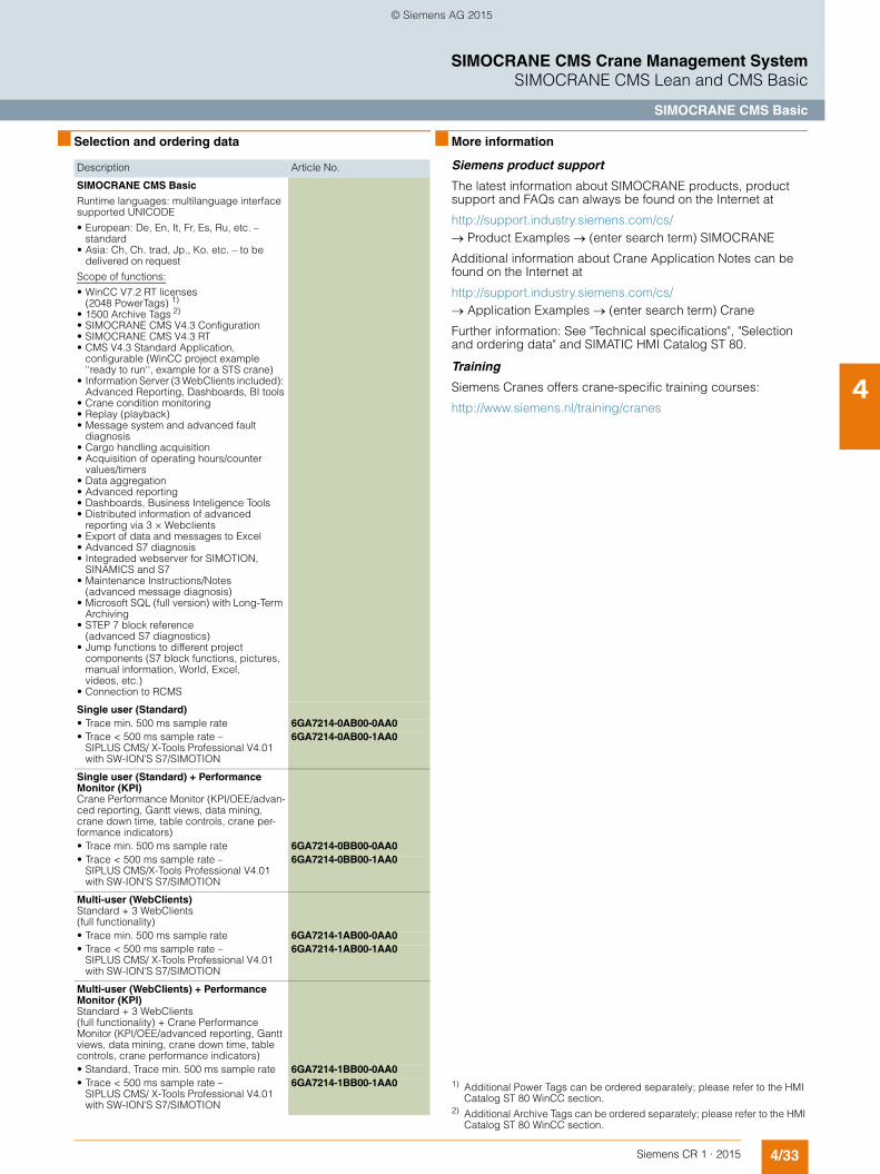
4/33Siemens CR 1 · 2015
4
SIMOCRANE CMS Crane Management SystemSIMOCRANE CMS Lean and CMS Basic
SIMOCRANE CMS Basic
■ Selection and ordering data ■ More information
Siemens product support
The latest information about SIMOCRANE products, product support and FAQs can always be found on the Internet at
http://support.industry.siemens.com/cs/→ Product Examples → (enter search term) SIMOCRANE
Additional information about Crane Application Notes can be found on the Internet at
http://support.industry.siemens.com/cs/→ Application Examples → (enter search term) Crane
Further information: See "Technical specifications", "Selection and ordering data" and SIMATIC HMI Catalog ST 80.
Training
Siemens Cranes offers crane-specific training courses:
http://www.siemens.nl/training/cranes
Description Article No.
SIMOCRANE CMS Basic
Runtime languages: multilanguage interface supported UNICODE
• European: De, En, It, Fr, Es, Ru, etc. – standard
• Asia: Ch, Ch. trad, Jp., Ko. etc. – to be delivered on request
Scope of functions:
• WinCC V7.2 RT licenses (2048 PowerTags) 1)
• 1500 Archive Tags 2)
• SIMOCRANE CMS V4.3 Configuration• SIMOCRANE CMS V4.3 RT• CMS V4.3 Standard Application,
configurable (WinCC project example ''ready to run'', example for a STS crane)
• Information Server (3 WebClients included): Advanced Reporting, Dashboards, BI tools
• Crane condition monitoring• Replay (playback)• Message system and advanced fault
diagnosis• Cargo handling acquisition• Acquisition of operating hours/counter
values/timers• Data aggregation• Advanced reporting• Dashboards, Business Inteligence Tools• Distributed information of advanced
reporting via 3 × Webclients• Export of data and messages to Excel• Advanced S7 diagnosis• Integraded webserver for SIMOTION,
SINAMICS and S7• Maintenance Instructions/Notes
(advanced message diagnosis)• Microsoft SQL (full version) with Long-Term
Archiving • STEP 7 block reference
(advanced S7 diagnostics)• Jump functions to different project
components (S7 block functions, pictures, manual information, World, Excel, videos, etc.)
• Connection to RCMS
Single user (Standard)• Trace min. 500 ms sample rate 6GA7214-0AB00-0AA0• Trace < 500 ms sample rate –
SIPLUS CMS/ X-Tools Professional V4.01 with SW-ION'S S7/SIMOTION
6GA7214-0AB00-1AA0
Single user (Standard) + Performance Monitor (KPI)Crane Performance Monitor (KPI/OEE/advan-ced reporting, Gantt views, data mining, crane down time, table controls, crane per-formance indicators)• Trace min. 500 ms sample rate 6GA7214-0BB00-0AA0• Trace < 500 ms sample rate –
SIPLUS CMS/X-Tools Professional V4.01 with SW-ION'S S7/SIMOTION
6GA7214-0BB00-1AA0
Multi-user (WebClients)Standard + 3 WebClients (full functionality)• Trace min. 500 ms sample rate 6GA7214-1AB00-0AA0• Trace < 500 ms sample rate –
SIPLUS CMS/ X-Tools Professional V4.01 with SW-ION'S S7/SIMOTION
6GA7214-1AB00-1AA0
Multi-user (WebClients) + Performance Monitor (KPI)Standard + 3 WebClients (full functionality) + Crane Performance Monitor (KPI/OEE/advanced reporting, Gantt views, data mining, crane down time, table controls, crane performance indicators)• Standard, Trace min. 500 ms sample rate 6GA7214-1BB00-0AA0• Trace < 500 ms sample rate –
SIPLUS CMS/ X-Tools Professional V4.01 with SW-ION'S S7/SIMOTION
6GA7214-1BB00-1AA0 1) Additional Power Tags can be ordered separately; please refer to the HMI Catalog ST 80 WinCC section.
2) Additional Archive Tags can be ordered separately; please refer to the HMI Catalog ST 80 WinCC section.
© Siemens AG 2015
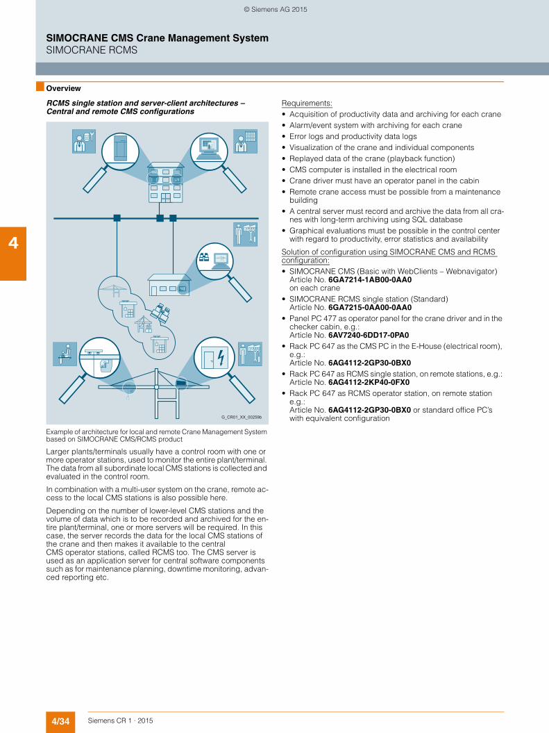
4/34 Siemens CR 1 · 2015
4
SIMOCRANE CMS Crane Management SystemSIMOCRANE RCMS
■ Overview
RCMS single station and server-client architectures – Central and remote CMS configurations
Example of architecture for local and remote Crane Management System based on SIMOCRANE CMS/RCMS product
Larger plants/terminals usually have a control room with one or more operator stations, used to monitor the entire plant/terminal. The data from all subordinate local CMS stations is collected and evaluated in the control room.
In combination with a multi-user system on the crane, remote ac-cess to the local CMS stations is also possible here.
Depending on the number of lower-level CMS stations and the volume of data which is to be recorded and archived for the en-tire plant/terminal, one or more servers will be required. In this case, the server records the data for the local CMS stations of the crane and then makes it available to the central CMS operator stations, called RCMS too. The CMS server is used as an application server for central software components such as for maintenance planning, downtime monitoring, advan-ced reporting etc.
Requirements:• Acquisition of productivity data and archiving for each crane• Alarm/event system with archiving for each crane• Error logs and productivity data logs• Visualization of the crane and individual components• Replayed data of the crane (playback function)• CMS computer is installed in the electrical room• Crane driver must have an operator panel in the cabin• Remote crane access must be possible from a maintenance
building• A central server must record and archive the data from all cra-
nes with long-term archiving using SQL database• Graphical evaluations must be possible in the control center
with regard to productivity, error statistics and availability
Solution of configuration using SIMOCRANE CMS and RCMS configuration:• SIMOCRANE CMS (Basic with WebClients – Webnavigator)
Article No. 6GA7214-1AB00-0AA0on each crane
• SIMOCRANE RCMS single station (Standard) Article No. 6GA7215-0AA00-0AA0
• Panel PC 477 as operator panel for the crane driver and in the checker cabin, e.g.: Article No. 6AV7240-6DD17-0PA0
• Rack PC 647 as the CMS PC in the E-House (electrical room), e.g.: Article No. 6AG4112-2GP30-0BX0
• Rack PC 647 as RCMS single station, on remote stations, e.g.: Article No. 6AG4112-2KP40-0FX0
• Rack PC 647 as RCMS operator station, on remote station e.g.: Article No. 6AG4112-2GP30-0BX0 or standard office PC’s with equivalent configurationG_CR01_XX_00259b
© Siemens AG 2015

4/35Siemens CR 1 · 2015
4
■ Overview (continued)
SIMOCRANE CMS Crane Management SystemSIMOCRANE RCMS
Example for solution configuration for an STS crane using SIMOCRANE CMS and RCMS
Further information: See "Technical specifications", "Selection and ordering data" and SIMATIC HMI Catalog ST 80.
Remark:
The SIMOCRANE RCMS is standard equipped with one RCMS WebClient with full access to the screens and all components of the RCMS single station. Additional WebClients can be added by buying extra WebClients, for example 3, 10, 50 and 150 Web-Clients can be connected to one RCMS single station. All Web-Clients are working in parallel, accessing the information at the same time. Different configurations using WebClients are possi-ble to be also added based on customer requirements.
TCP/IP connection(cable or wireless)
SIMOCRANE CMS (Server)
Checker Cabin(Client)
E-HouseDriver Cabin(Client)
Local station (Crane)
Remote station (Office)
MicrosoftSQL
G_CR01_EN_00360
SIMOCRANE RCMS
© Siemens AG 2015

4/36 Siemens CR 1 · 2015
4
■ Overview (continued)
SIMOCRANE CMS Crane Management SystemSIMOCRANE RCMS
Typical configuration for SIMOCRANE RCMS single station with WebClients
SIMOCRANE CMS & RCMS WebClients
Terminal
SIMOCRANE RCMS Server
G_CR01_EN_00361
SIMOCRANE CMS
© Siemens AG 2015

4/37Siemens CR 1 · 2015
4
■ Overview (continued)
SIMOCRANE CMS Crane Management SystemSIMOCRANE RCMS
Control Room solutions using SIMOCRANE CMS and RCMS
Using the standard package in combination with optional pa-ckages of SIMOCRANE CMS and RCMS products, control room solutions can be provided. Such solutions are based on software and hardware packages in different combinations depending on customer requirements related to the number of client stations being used for data access, number of RCMS servers used in the data center mainframe architecture systems, number of webclients with simultaneous access to different Microsoft SQL databases in SIMOCRANE CMS stations or RCMS servers, etc.
For control room solutions, hardware systems based on SIMATIC IPC and Panel PC with multi touch functionality are integrated together with SIMOCRANE CMS & RCMS software solutions. Siemens can provide different solutions for state of the art control room solutions, using robust industrial hardware sys-tems with large data storage capabilities, mirroring RAID cont-rollers, back-up systems, redundant hardware equipment for achieving 100 % system availability for any harsh industrial con-ditions.
Example of control room solution for connection of different SIMOCRANE CMS and RCMS stations distributed through different locations
SIMOCRANE CMS & RCMS WebClients
Central LocationControl Room
Terminal Location A
G_CR01_EN_00364
SIMOCRANE CMS
SIMOCRANERCMS server
SIMOCRANERCMS server
SIMOCRANERCMS server
Terminal Location B
SIMOCRANE CMS
Terminal Location C
SIMOCRANE CMS
© Siemens AG 2015

4/38 Siemens CR 1 · 2015
4
SIMOCRANE CMS Crane Management SystemSIMOCRANE RCMS
■ Application
• Large harbor crane systems, such as container terminals.
In addition to the diagnostic possibilities on the individual crane, productivity data acquisition and reporting play a decisive role. The availability of acquired cargo handling data, downtimes as
well as performance data are important aspects regarding crane terminal operation and data mining.
Examples• Ship to shore cranes and grab cranes (bulk goods) in the har-
bor area
■ Design
SIMOCRANE RCMS architecture
Topology of SIMOCRANE RCMS standard package (one WebClient included in the standard package)
Remarks:
SIMOCRANE RCMS is delivered standard with one RCMS WebClient. Additional WebClients can be ordered sepa-rate, to a maximum of 150 WebClients.
The customer has maximum flexibility regarding the access of information from each RCMS station. When needed, additional RCMS clients can be added or control room solution can be built in order to access the information from RCMS SQL database. RCMS is equipped with a Microsoft SQL database included standard in the RCMS package. This includes data storage with long-term archive capabilities integrated into the SCADA WinCC system.
G_C
R01
_EN
_003
62
LAN
SIMOCRANE RCMS WebClients
Microsoft SQL
SIMOCRANE CMS Lean or SIMOCRANE CMS Basic
SIMOCRANE CMS Lean or SIMOCRANE CMS Basic
SIMOCRANE CMS Lean or SIMOCRANE CMS Basic
SIMOCRANE RCMS Diagnosis PC
Crane #nCrane #2Crane #1
© Siemens AG 2015

4/39Siemens CR 1 · 2015
4
■ Design (continued)
SIMOCRANE CMS Crane Management SystemSIMOCRANE RCMS
RCMS server-single or RCMS server-client architectures
With this configuration, the server is also the central operator sta-tion with access to the lower-level CMS systems or the server is connected to multiple clients.
Especially in harbor applications, multiple RCMS server stations can be sued in order to distribute the information to different RCMS client systems. The RCMS clients have own database, which makes possible the data transferred from different RCMS servers to be merged and perform advanced reports from diffe-rent CMS and RCMS stations at the same time.
Using standard Internet or Intranet web-based connections, fat or thin clients can be connected in different terminal access points in order to access the data from Microsoft SQL database, long-term archived server. These web-based clients can be mo-bile devices as PC tables or smart phones using modern mobile technologies for data access in Intranet or/and Internet environ-ment. The connection via Internet/Intranet is encrypted in order to provide secure connections from the mobile devices.
RCMS multiple server-clients configuration architecture
G_CR01_EN_00363
LAN
Remote Diagnose/Mobile PC
Fat and Thin web-based CMS / RCMS Clients
Crane #nCrane #2Crane #1
RCMS clients
RCMS serverRCMS serverRCMS server
SIMOCRANE CMS SIMOCRANE CMS SIMOCRANE CMS
© Siemens AG 2015

4/40 Siemens CR 1 · 2015
4
SIMOCRANE CMS Crane Management SystemSIMOCRANE RCMS
■ Function
RCMS central server and remote CMS
The central CMS functions concern the operation of CMS opera-tor stations in central control rooms. In the context of harbor cra-nes, the term "RCMS" (Remote CMS) has become established.• As well as offering remote access to the CMS stations of the
cranes, the central RCMS offers additional functions such as:• Plant-wide crane overview• Remote access to individual cranes• Central data acquisition and evaluation• Availability overview and Gantt charts• Performance evaluation• Excel reporting tool for data evaluation and exporting from
MS SQL from CMS and RCMS• Replay/Playback from RCMS on each CMS using WebClient
functionality• Long-Term Archiving in MS SQL on RCMS
The central RCMS focuses on the entire plant, not the single crane. Cranes of the same type can be compared and weak points therefore detected. The determination of KPIs (Key Per-formance Indicators) and overviews of operating modes, down-times etc. plays a key role at this point.
Given the volume of information that has to be displayed, we would recommend using large screens or even multi-screen mode. The system also supports the use of the large screens, commonly used in the control rooms of large industrial plants or control centers.
Plant-wide crane overview
The plant-wide crane overview is a project-oriented plant display based on a layout plan. The project engineer stores this plan as background in a format that is suitable for WinCC. Individual cra-nes are depicted using symbols. This display is not included in the scope of the product, but the data interface is provided.
Example of screen for RCMS – statistical overview
An alternative display is the hierarchic view as a topology tree. The different types of crane are displayed here in groups. The status of the individual cranes is visualized using different colors.
Example of screen for RCMS – node tree manager and cartographical overview
Remote access to individual cranes
In the crane overview node tree manager, a crane can be selec-ted and the CMS interface of this crane can be displayed via re-mote access. Full access of the crane is possible from RCMS via WebNavigator option on CMS station.
Example of integrated remote access of CMS into RCMS
Central data acquisition and evaluation
The cargo handling data, error messages, and counter values acquired for each crane are synchronized with the RCMS server. This server makes the consolidated data for all assigned cranes available for further evaluations. All data from different cranes (CMS stations), e.g. operational data, tags, messages, are sent to the remote RCMS. The Remote CMS (RCMS) can be also called as ‘’central CMS station’’, which means there is a central station where the data from all cranes are collected. An RCMS has a Microsoft SQL database with Long-Term Archive integra-ted into WinCC station. This means the data is stored for long term in a Microsoft SQL database. The configuration for seg-ments and data backup is to be configured at the beginning of the project for RCMS configuration. More details please refer to the CMS manuals and WinCC information on the support site.
On the RCMS a central fault message system is applied in order to perform statistics and filtering of fault messages for each crane in the terminal. Statistical analysis for all messages can be performed in the message window on RCMS station. Compre-hensive message evaluation can be performed as well in the WinCC message system in combination with CMS and RCMS message tables from SQL.
© Siemens AG 2015

4/41Siemens CR 1 · 2015
4
■ Function (continued)
SIMOCRANE CMS Crane Management SystemSIMOCRANE RCMS
RCMS – message list for one crane
RCMS – message list for all cranes in the terminal
Crane operational data on RCMS – list with moves per crane
Using the node tree manager structure on the RCMS, informa-tion about operational data for each crane can be obtained when clicking in the node tree on the required crane. In a tabular from an overview with the most important data is shown. Filtering and data export can be performed on each individual crane.
Remote system activation from RCMS on the crane (CMS station)
From RCMS each crane can be accessed in parallel remotely in order to visualize the screens from each local CMS. Full access to screens as well full commands can be obtained from the RCMS via WebNavigator option installed on each CMS. Several sessions in parallel can be started from RCMS and parallel sta-tistical data overview can be performed from RCMS individually for each CMS. The sessions can be started at the same time in different sessions from RCMS and CMS as well – when the ope-rator is operating the crane from local CMS, on the RCMS diffe-rent information can be visualized remotely.
Availability overview and Gantt charts
The WinCC option Performance Monitor continuously acquires the operating states of all assigned cranes. This enables the operator to determine the availability of the cranes at any time and to detect weak points. The information is visualized in a Gantt chart with information about statuses of the cranes on the RCMS station. The overview of the Gantt chart can be visualized for each crane or for more crane sin parallel. In this way data from different cranes can be compared and weak points are to be identified in the Gantt charts.
The crane availability is easy to be visualized and extra informa-tion can be obtained by clicking on each crane. Different time in-tervals can be chosen in order to visualize the information from the past.
Gantt chart of cranes availability
© Siemens AG 2015
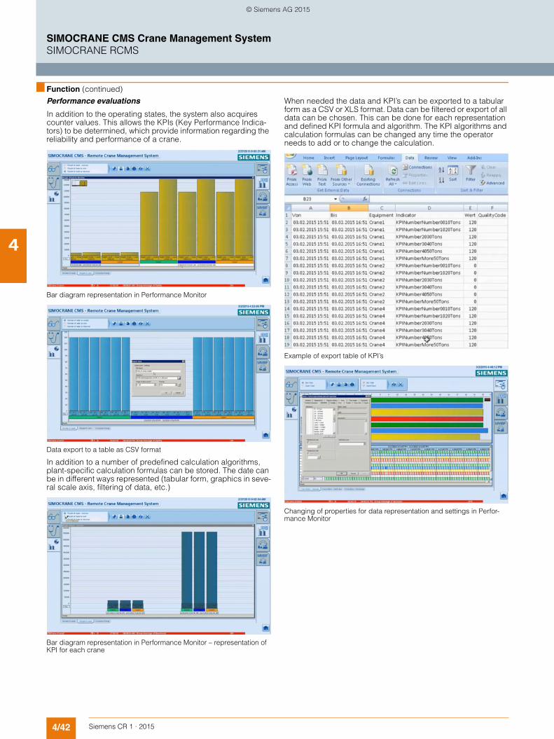
4/42 Siemens CR 1 · 2015
4
■ Function (continued)
SIMOCRANE CMS Crane Management SystemSIMOCRANE RCMS
Performance evaluations
In addition to the operating states, the system also acquires counter values. This allows the KPIs (Key Performance Indica-tors) to be determined, which provide information regarding the reliability and performance of a crane.
Bar diagram representation in Performance Monitor
Data export to a table as CSV format
In addition to a number of predefined calculation algorithms, plant-specific calculation formulas can be stored. The date can be in different ways represented (tabular form, graphics in seve-ral scale axis, filtering of data, etc.)
Bar diagram representation in Performance Monitor – representation of KPI for each crane
When needed the data and KPI’s can be exported to a tabular form as a CSV or XLS format. Data can be filtered or export of all data can be chosen. This can be done for each representation and defined KPI formula and algorithm. The KPI algorithms and calculation formulas can be changed any time the operator needs to add or to change the calculation.
Example of export table of KPI’s
Changing of properties for data representation and settings in Perfor-mance Monitor
© Siemens AG 2015

4/43Siemens CR 1 · 2015
4
■ Function (continued)
SIMOCRANE CMS Crane Management SystemSIMOCRANE RCMS
Microsoft SQL data retrieving and reporting using Excel
From the version V4.3 of SIMOCRANE CMS the possibility to easy extract the data from Microsoft (MS) SQL for CMS and RCMS is offered by using standard Microsoft programs such as Excel. The MS Excel can be installed on any office PC in the ter-minal. The PC should have access to the CMS or RCMS stations in the network. No installation of CMS or RCMS on the office PC is required, only a plug in for data access on the MS SQL data-base in order to facilitate the connection from a remote PC to the
local MS SQL database. The Excel reporting tool needs to be configured in the beginning, regarding the name of the PC and the IP address. The operational data (moves, counters, timers, etc.) and other data stored in the archive tags on CMS or RCMS can be easily accessed remotely from an office PC. Fault mes-sage scan be retrieved as well as statistical analysis can be per-formed from different message groups.
Microsoft Excel tool for data retrieving and data representation/reporting from MS SQL databases on CMS and RCMS
G_CR01_EN_00370
LAN
Office PC (no installation of CMS/RCMS)
Microsoft SQL
SIMOCRANE CMS Lean or SIMOCRANE CMS Basic
SIMOCRANE CMS Lean or SIMOCRANE CMS Basic
SIMOCRANE CMS Lean or SIMOCRANE CMS Basic
SIMOCRANE RCMS
Crane #nCrane #2Crane #1
MS Excel 2010(xls)
© Siemens AG 2015
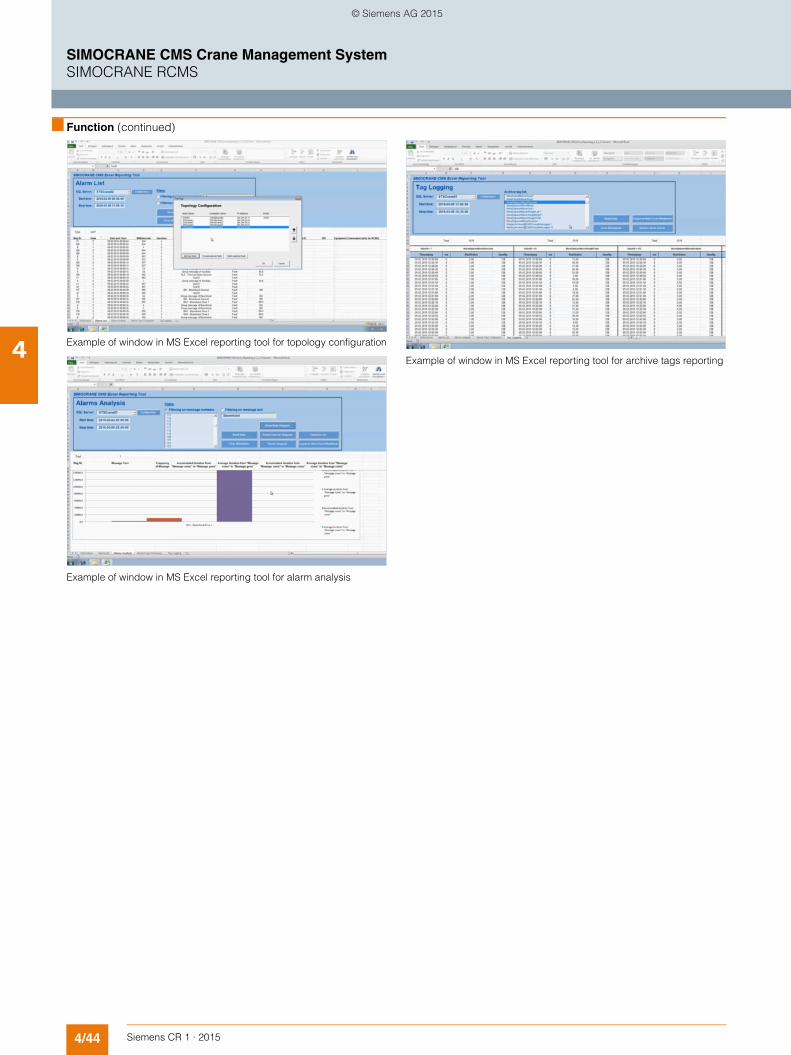
4/44 Siemens CR 1 · 2015
4
■ Function (continued)
SIMOCRANE CMS Crane Management SystemSIMOCRANE RCMS
Example of window in MS Excel reporting tool for topology configuration
Example of window in MS Excel reporting tool for alarm analysis
Example of window in MS Excel reporting tool for archive tags reporting
© Siemens AG 2015

4/45Siemens CR 1 · 2015
4
SIMOCRANE CMS Crane Management SystemSIMOCRANE RCMS
Recommended hardware configuration
■ Configuration
Hardware configurations from the SIMATIC IPC and SIMATIC Panel PC range are recommended for SIMOCRANE CMS and RCMS software packages. In accordance with the recommen-
dations, alternative computer hardware can also be used. Please enquiry in order to check the chosen hardware configu-ration in combination with RCMS software components.
Recommended hardware configurations for RCMS
Industrial hardware from SIMATIC family IPC and Panel PC’s from Siemens used for SIMOCRANE CMS and RCMS stations on local station or/and remote stations)
SIMOCRANE RCMS serverSIMATIC IPC647 or IPC847 orOffice PC
1 - 2 displays if necessary, preferably widescreen format
Processor Core i7, or better performance Memory configuration Minimum 16 GBHard drive RAID1, 2 × 1 Tb or moreOptical drives DVD±RGraphics card 2 × DVI or 2 × VGACommunications interfaces 2 × EthernetOther interfaces USBOperating system Windows Server 2008 R2 (64 bit)
SIMOCRANE RCMS operator stationSIMATIC IPC647 or IPC847 orOffice PC
1 - 2 displays if necessary, preferably widescreen format
Processor Core i5, or better performanceMemory configuration Minimum 8 GBHard drive 1 Tb or more (as option RAID controller)Optical drives DVD±RGraphics card 2 × DVI or 2 × VGACommunications interfaces EthernetOther interfaces USBOperating system Windows 7 SP1 (64 bit)
Rack PC
HW applied in most crane applications
Box PC Panel PC
Clo
sene
ss to
mac
hine
G_CR01_EN_00365
Identical mainboard
base
2xx series optimized
performance, highly compactEmbedded industrial PC
Highly rugged Highly compact
Maintenance-free – no fan
High-end industrial PCs Very rugged
High performance High functionality
Industrial PC Robust
Attractive price
6xx series compact
8xx series expandable
4xx series high
performance, highly compact
5xx series maximum
performance, expandable, latest
PC technology
3xx series high performance,
optimized price
Identical mainboard
base
Identical mainboard
base
IPC277DIPC227D
IPC427D
IPC627D
IPC827D
IPC647D
IPC847D
IPC547D
IPC347D
IPC477D
IPC677D
© Siemens AG 2015

4/46 Siemens CR 1 · 2015
4
SIMOCRANE CMS Crane Management SystemSIMOCRANE RCMS
■ Technical specifications
Ordering packages SIMOCRANE RCMS
Standard (1 WebClient)
Standard + extra WebClients(3, 10, 50 and 150)
Standard + Operator station
Type 6GA7215-0AA00-0AA0 6GA7215-0.A00-0AA0 6GA7215-1.A00-0AA0
Crane overview
• Cartographic plant overview (example only map can be addapted)
- Zooming and scrolling possible - Dynamic position display - Status display (operation, fault, maintenance, etc.) - Call-up of detailed information per crane
• Hierarchic tree structure for cranes and types - Status display (operation, fault, maintenance, etc.) - Call-up of detailed information per crane
Remote access
• Remote access to the CMS of the selected crane • Calling up the trace data for a crane • Performing Replay/Playback from RCMS via WebClient
Performance evaluations
• Operating status overview as Gantt chart - Downtimes overview - Operating times - Maintenance
• Performance evaluation for cargo handling data - Cargo handling per hour - Evaluation based on handled cargo (e.g. container sizes) - Evaluation based on weights moved
• KPI‘s per crane - KPI‘s for a group of cranes or entire terminal - MMBF values (Mean Moves Between Failures) - Customer-specific KPIs (configurable)
Graphic evaluations
• Message statistics • Counter and operating hours values • Cargo handling data as tables or graphics • Messages for the assigned cranes
Long-term archiving (Microsoft SQL database)
• Operating hours values • Counter and operating hours values • Customer-specific values (configurable)
System features
• WebClients for remote screens and data access (1 × WebClient)
– –
• WebClients for remote screens and data access (additional WebClients to a max. of 150)
–
• 128 process tags 1) • Up to 32 RCMS operator stations can be used – – • Archive tags – – –
- 512 archive tags 2) – – - 5000 archive tags 3) –
• Data evaluation & advanced reporting (Information Server – standard 3 Clients)
• Crane Performance Monitor & KPI calculation 4) • CMS to RCMS connection 5) • Office PC EXCEL Reporting Tool of SQL database – Crane
Excel Workbook (connection to CMS and RCMS)
• Microsoft SQL Server (long-term archiving) delivered stan-dard with RCMS
– Not included in the scope of delievery
Included in the scope of delievery
1) No standard connection to PLC on RCMS. Only on request to be deli-vered.
2) Extra tags for local operator station.3) Standard delivered with RCMS – possible to be extended to max. 120000
Archive Tags for each RCMS station.4) Standard with RCMS 1500 Performance Monitor (PMO) archive tags for
KPI definition in SQL database are provided. Up to 5000 PMO archive tags are tested in WinCC V7.2.
5) Maximum number of CMS stations connected to one RCMS depends of data volume and maximum data handling by WinCC and SQL (to be che-cked in CMS manuals). For more information please get in contact with hotline CMS or application support.
© Siemens AG 2015

4/47Siemens CR 1 · 2015
4
SIMOCRANE CMS Crane Management SystemSIMOCRANE RCMS
■ Selection and ordering data ■ More information
Siemens product support
The latest information about SIMOCRANE products, product support and FAQs can always be found on the Internet at
https://support.industry.siemens.com/cs/→ Product Support → (Enter search term) SIMOCRANE
Additional information about Crane Application Notes can be found on the Internet at
https://support.industry.siemens.com/cs/→ Application Examples → (Enter search term) Crane
Further information: See "Technical specifications", "Selection and ordering data" and SIMATIC HMI Catalog ST 80.
Training
Siemens Cranes offers crane-specific training courses:
http://www.siemens.nl/training/cranes
Description Article No.
SIMOCRANE RCMS serverRuntime languages: multilanguage interface supported UNICODE
• European: De, En, It, Fr, Es, Ru, etc. – standard
• Asia: Ch, Ch. trad, Jp., Ko.etc. – to be delivered on request
Scope of functions:
• Central message and advanced fault diagnosis in Microsoft SQL database
• Central Archive Tag system in Microsoft SQL database
• Microsoft SQL license delivered with RCMS
• Cranes and terminal overview(Tree Manager, Plant Model)
• Interactive maps• Remote maintenance• Standard 1 × RCMS WebClient• Remote access to cranes, individual or
in parallel• Cargo handling acquisition• Acquisition of operating hours/counter
values/timers• Data aggregation• Advanced reporting• Dashboards, Business Inteligence Tools• Export of data and messages to Excel• Advanced S7 diagnosis on CMS from
RCMS• Replay function on CMS from RCMS for
each crane• Webserver SIMOTION, SINAMICS and S7
remote from RCMS• Microsoft SQL including Long-Term
Archive server + Backup• Crane Performance Monitor
(KPI, OEE, Gantt views, advanced reporting, data mining, crane down time monitoring, table controls)
SIMOCRANE RCMS server – Single station
(No connection to RCMS operator stations) • 1 RCMS WebClient (Standard) 6GA7215-0AA00-0AA0• 3 RCMS WebClients 6GA7215-0BA00-0AA0• 10 RCMS WebClients 6GA7215-0CA00-0AA0• 50 RCMS WebClients 6GA7215-0DA00-0AA0• 150 RCMS WebClients 6GA7215-0EA00-0AA0
SIMOCRANE RCMS server + operator station
(Possible to connect up to 32 RCMS opera-tor stations – Clients in parallel)• 1 RCMS WebClient (Standard) 6GA7215-1AA00-0AA0• 3 RCMS WebClients 6GA7215-1BA00-0AA0• 10 RCMS WebClients 6GA7215-1CA00-0AA0• 50 RCMS WebClients 6GA7215-1DA00-0AA0• 150 RCMS WebClients 6GA7215-1EA00-0AA0
© Siemens AG 2015

4/48 Siemens CR 1 · 2015
4
SIMOCRANE CMS Crane Management SystemSIMOCRANE CMS and RCMS upgrade packages
■ Overview
SIMOCRANE CMS and RCMS upgrade packages
In order to make upgrades from previous versions to the latest version of SIMOCRANE CMS V4.3, upgrade packages are of-fered with separate article numbers. Therefore, when in the terminal are already cranes equipped with versions CMS V4.2 (or CMS V4.1), crossing combinations are possible, but limita-tions due to different versions used are to be taken into account (please refer to the customer support web page for more infor-mation). When in the terminal new cranes are added to the exis-ting ones, using CMS upgrade packages the already installed CMS packages can be upgraded to the latest version available, of version V4.3. In order to upgrade CMS Lean to CMS Basic, upgrade packages are also available.
The following upgrade packages can be ordered:• Upgrade license from SIMOCRANE CMS Lean to CMS Basic
package• Upgrade license from SIMOCRANE CMS V 4.1, V4.1 SP1 and
V4.2 to CMS V4.3• Upgrade license from SIMOCRANE RCMS V 4.1,
V4.1 SP1 and V4.2 to RCMS V4.3
The upgrade licenses for CMS Lean to CMS Basic includes the extra licenses for WinCC Power Tags and Archive Tags. The other options contained in CMS Lean will be as well valid for CMS Basic. For the upgrades of CMS & RCMS older versions to V4.3, upgrades for WinCC tags and options are delivered with the upgrade licenses. Please refer to the section CMS & RCMS ordering data specifications and upgrade packages.
When using SIMOCRANE upgrade licenses, please check CMS application project. For migration of older versions, migration of projects for CMS configuration and CMS application should be considered.
■ Selection and ordering data
Description Article No.
Upgrade SIMOCRANE CMS V4.3 Lean Package to Basic Package
6GA7216-0AA00-0AA0
• WinCC 7.2 RT Upgrade 512 to 2048 Tags• WinCC Archive 1500 Tags• Runtime languages: multilanguage inter-
face supported UNICODE - European: De, En, It, Fr, Es, Ru, etc. –
standard- Asia: Ch, Ch. trad, Jp., Ko. etc. – to be
delivered on request• SIMOCRANE CMS V4.3 RT• SIMOCRANE CMS V4.3 Configuration• CMS V4.3 Standard Application, configu-
rable (WinCC project example ''ready to run'')
Upgrade SIMOCRANE CMS Package V4.1, V4.1SP1, V4.2 to V4.3
6GA7216-0AB00-0AA0
• WinCC 6.2 RT & 7.0 RT Upgrade to WinCC 7.2 RT
• Upgrade WebNavigator• Upgrade DataMonitor• Update WinCC Archive • Runtime languages: multilanguage inter-
face supported UNICODE - European: De, En, It, Fr, Es, Ru, etc. –
standard- Asia: Ch, Ch. trad, Jp., Ko. etc. – to be
delivered on request• SIMOCRANE CMS V4.3 RT (Runtime)• SIMOCRANE CMS V4.3 Configuration• CMS V4.3 Standard Application, configu-
rable (WinCC project example ''ready to run'', CMS HMI Interface)
Upgrade SIMOCRANE RCMS Package V4.1, V4.1SP1, V4.2 to V4.3
6GA7216-0AC00-0AA0
• RCMS V4.3 RT (Runtime)• RCMS V4.3 Configuration• RCMS V4.3 Standard Application
(WinCC Project example)• WinCC 6.2 RT & 7.0 RT Upgrade to
WinCC 7.2 RT• Upgrade Web.Navigator• Upgrade DataMonitor• Update WinCC Archive• Upgrade DownTimeMonitor to Perfor-
mance Monitor• Information Server 3 × WebClients• Runtime languages: multilanguage inter-
face supported UNICODE - European: De, En, It, Fr, Es, Ru, etc. –
standard- Asia: Ch, Ch. trad, Jp., Ko. etc. – to be
delivered on request
© Siemens AG 2015

4/49Siemens CR 1 · 2015
4
SIMOCRANE CMS Crane Management SystemAdditional components
■ Overview
Products that are listed below are not components of the SIMOCRANE CMS & RCMS packages. These additional compo-nents are recommended to perform extra tasks on the CMS or/and on the RCMS stations. Such components described here can be ordered separately based on WinCC options and add-ons. Please read the technical specifications and ordering infor-mation at the specified Internet address. Also for more informa-tion or enquiry, please take contact with the CMS Application Support department.
■ Function
WinCC Add-on PM-Maint for maintenance jobs registration and handling on CMS/RCMS
This is a complete maintenance planning system that can be centrally implemented for the entire plant, or even be locally im-plemented on the crane. PM-Maint is a maintenance manage-ment system from Siemens designed to be used close to the shop floor level. By providing various connectivity options to the existing automation landscape PM-Maint allows besides purely calendar based planning also a performance based planning of job maintenance that is based on real operating hours and ope-ration cycles. PM-Maint supports the maintenance process also for the recording of jobs and complete documentation of unplan-ned repairs by providing easy and comprehensible workflows combined with a high degree of ease of use.
Various views with comfortable filter and formatting rules can be personalized for individual users, user groups or globally for all users. Transparent access to your maintenance information is ensured by web compatible client server architecture. At any time and from any location.
PM-MAINT user interface displaying the “orders” view
Characteristics of PM-MAINT:• Automatic calculation of the recommended maintenance
dates under consideration of the utilization• Optimum resource planning notification prior to order due
date• Clear display of planned orders, notifications and active
orders with comfortable selection and filtering functions• Central material list for required material and tools• Linking of documents (graphs, photos, data sheet, etc.) to
plant objects and planned orders• Manual orders for planned activities (repairs)• Long-term archive for all maintenance activities• Excel Plug-in for comfortable mass data import• Write back capability for maintenance metrics into HMI tags• Multiple order feedbacks with recording of
- Feedback Data (e.g. object state, type of performed action)- Cost and time input for personal- Cost and used quantities for material
© Siemens AG 2015
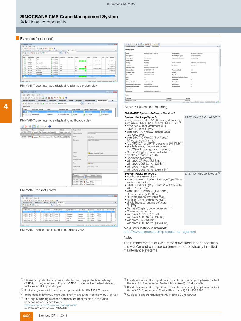
4/50 Siemens CR 1 · 2015
4
■ Function (continued)
SIMOCRANE CMS Crane Management SystemAdditional components
PM-MAINT user interface displaying planned orders view
PM-MAINT user interface displaying notification view
PM-MAINT request control
PM-MAINT notifications listed in feedback view
PM-MAINT example of reporting
More Information in Internet: http://www.siemens.com/process-management
Note:
The runtime meters of CMS remain available independently of this AddOn and can also be provided for previously installed maintenance systems.
PM-MAINT System Software Version 9 System Package Type S 7) 9AE7 104-2SS30-1AA0-Z 1)
• Single-user system/Multi-user system server • inclusive PM-SERVER 2) and PM-AGENT 3)
• executable in environment with SIMATIC WinCC (V6/7),
• with SIMATIC WinCC flexible 2008 (via OPC DA),
• with SIMATIC WinCC (TIA Portal) RT Advanced (V11/12)
• (via OPC DA) and RT Professional (V11/12) 4), • single license, runtime software
(R-SW) incl. Configuration system, • German/English, copy protection 1)
• electronic manual on CD. • Operating systems: • Windows XP Prof. (32 Bit),
Windows 2003 Server (32 Bit), • Windows 7 (32/64 Bit),
Windows 2008 Server (32/64 Bit) System Package Type C 7) 9AE7 104-4SC00-1AA0-Z 1)
• Multi-user system client • executable with System Package Type S in an
environment with • SIMATIC WinCC (V6/7), with WinCC flexible
2008 PC runtime, • with SIMATIC WinCC (TIA Portal)
RT Advanced (V11/12) and • RT Professional (V11/12) 4) or • as Thin Client (without WinCC), • single license, runtime software
(R-SW), • German/English, copy protection 1). • Operating systems: • Windows XP Prof. (32 Bit),
Windows 2003 Server (32 Bit), • Windows 7 (32/64 Bit),
Windows 2008 Server (32/64 Bit)
1) Please complete the purchase order for the copy protection delivery: -Z U02 = Dongle for an USB port; -Z S03 = License file. Default delivery includes an USB port dongle.
2) Exclusively executable on the computer with the PM-MAINT server.3) In the case of a WinCC multi-user system executable on the WinCC server.4) The legally binding released versions are documented in the latest
released notes. Please look at www.siemens.com/process-management → Premium Add ons → PM-MAINT
5) For details about the migration support for a user project, please contact the WinCC Competence Center. Phone: (+49) 621 456-3269
6) For details about the migration support for a user project, please contact the WinCC Competence Center. Phone: (+49) 621 456-3269
7) Subject to export regulations AL: N and ECCN: 5D992
© Siemens AG 2015
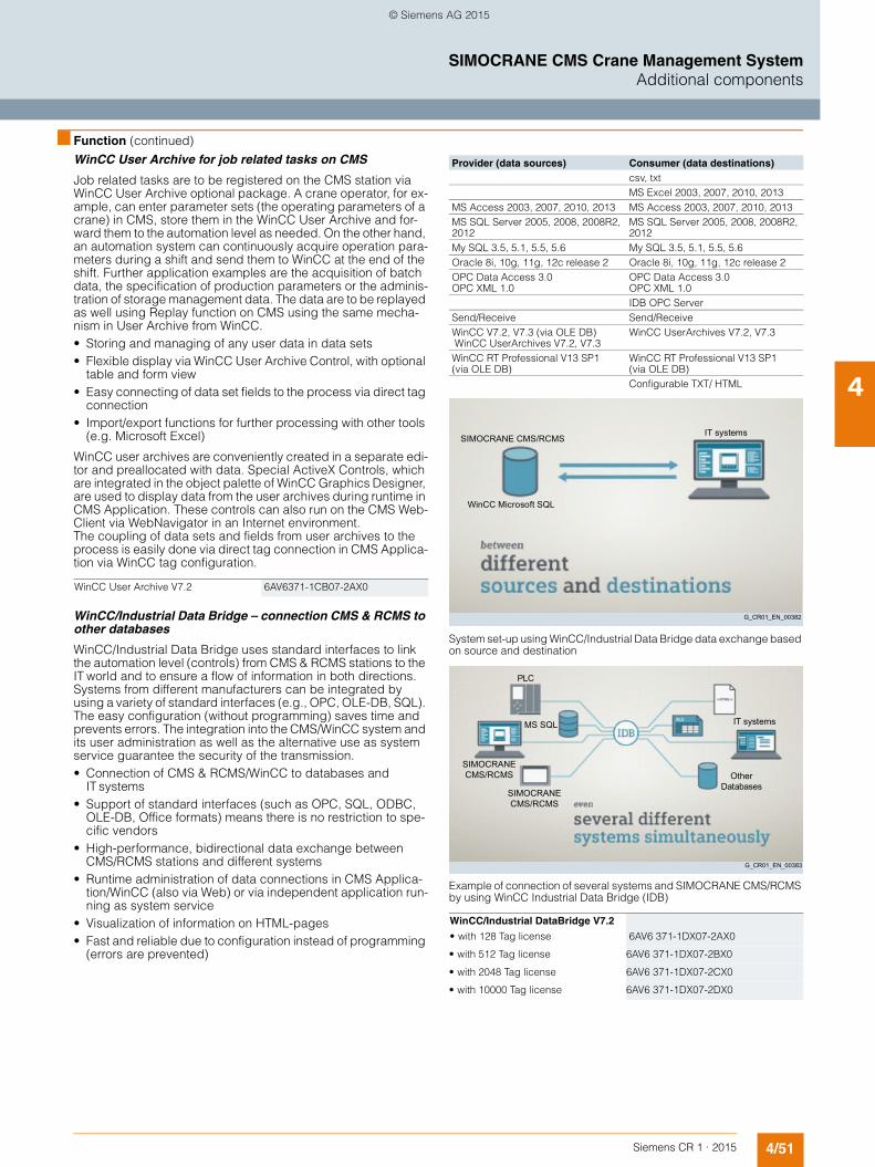
4/51Siemens CR 1 · 2015
4
■ Function (continued)
SIMOCRANE CMS Crane Management SystemAdditional components
WinCC User Archive for job related tasks on CMS
Job related tasks are to be registered on the CMS station via WinCC User Archive optional package. A crane operator, for ex-ample, can enter parameter sets (the operating parameters of a crane) in CMS, store them in the WinCC User Archive and for-ward them to the automation level as needed. On the other hand, an automation system can continuously acquire operation para-meters during a shift and send them to WinCC at the end of the shift. Further application examples are the acquisition of batch data, the specification of production parameters or the adminis-tration of storage management data. The data are to be replayed as well using Replay function on CMS using the same mecha-nism in User Archive from WinCC. • Storing and managing of any user data in data sets• Flexible display via WinCC User Archive Control, with optional
table and form view• Easy connecting of data set fields to the process via direct tag
connection• Import/export functions for further processing with other tools
(e.g. Microsoft Excel)
WinCC user archives are conveniently created in a separate edi-tor and preallocated with data. Special ActiveX Controls, which are integrated in the object palette of WinCC Graphics Designer, are used to display data from the user archives during runtime in CMS Application. These controls can also run on the CMS Web-Client via WebNavigator in an Internet environment.The coupling of data sets and fields from user archives to the process is easily done via direct tag connection in CMS Applica-tion via WinCC tag configuration.
WinCC/Industrial Data Bridge – connection CMS & RCMS to other databases
WinCC/Industrial Data Bridge uses standard interfaces to link the automation level (controls) from CMS & RCMS stations to the IT world and to ensure a flow of information in both directions. Systems from different manufacturers can be integrated by using a variety of standard interfaces (e.g., OPC, OLE-DB, SQL). The easy configuration (without programming) saves time and prevents errors. The integration into the CMS/WinCC system and its user administration as well as the alternative use as system service guarantee the security of the transmission.• Connection of CMS & RCMS/WinCC to databases and
IT systems• Support of standard interfaces (such as OPC, SQL, ODBC,
OLE-DB, Office formats) means there is no restriction to spe-cific vendors
• High-performance, bidirectional data exchange between CMS/RCMS stations and different systems
• Runtime administration of data connections in CMS Applica-tion/WinCC (also via Web) or via independent application run-ning as system service
• Visualization of information on HTML-pages• Fast and reliable due to configuration instead of programming
(errors are prevented)
System set-up using WinCC/Industrial Data Bridge data exchange based on source and destination
Example of connection of several systems and SIMOCRANE CMS/RCMS by using WinCC Industrial Data Bridge (IDB)
WinCC User Archive V7.2 6AV6371-1CB07-2AX0
Provider (data sources) Consumer (data destinations)csv, txtMS Excel 2003, 2007, 2010, 2013
MS Access 2003, 2007, 2010, 2013 MS Access 2003, 2007, 2010, 2013MS SQL Server 2005, 2008, 2008R2, 2012
MS SQL Server 2005, 2008, 2008R2, 2012
My SQL 3.5, 5.1, 5.5, 5.6 My SQL 3.5, 5.1, 5.5, 5.6Oracle 8i, 10g, 11g, 12c release 2 Oracle 8i, 10g, 11g, 12c release 2OPC Data Access 3.0 OPC XML 1.0
OPC Data Access 3.0 OPC XML 1.0IDB OPC Server
Send/Receive Send/ReceiveWinCC V7.2, V7.3 (via OLE DB) WinCC UserArchives V7.2, V7.3
WinCC UserArchives V7.2, V7.3
WinCC RT Professional V13 SP1(via OLE DB)
WinCC RT Professional V13 SP1 (via OLE DB)Configurable TXT/ HTML
WinCC/Industrial DataBridge V7.2
• with 128 Tag license 6AV6 371-1DX07-2AX0
• with 512 Tag license 6AV6 371-1DX07-2BX0
• with 2048 Tag license 6AV6 371-1DX07-2CX0
• with 10000 Tag license 6AV6 371-1DX07-2DX0
IT systems
WinCC Microsoft SQL
G_CR01_EN_00382
SIMOCRANE CMS/RCMS
G_CR01_EN_00383
Other Databases
IT systemsMS SQL
SIMOCRANE CMS/RCMS
SIMOCRANE CMS/RCMS
PLC
© Siemens AG 2015

4/52 Siemens CR 1 · 2015
4
■ Function (continued)
SIMOCRANE CMS Crane Management SystemAdditional components
Connectivity Pack – sending data via OPC interfaces from CMS and RCMS to other systems
WinCC has as standard an integrated OPC DA 3.0 server (Data Access) that gives you access to all the online values in the SIMOCRANE CMS/RCMS system and, on the other hand, can as a client read data from another application - across the Web too. The WinCC/Connectivity Pack offers additional options for al-ready existed SIMOCRANE CMS & RCMS stations.
This means that the system can transfer pre-processed process and production data of a crane to higher level systems for infor-mation conditioning (e.g. Manufacturing Execution Systems,
Enterprise Resource Planning systems or office packages, e.g. Microsoft Excel, Microsoft Access, etc.) and TOS systems.• Simple IT and business integration by means of standard
interface from SIMOCRANE CMS & RCMS stations• Access to online and historical data from any computers you
like via standard interfaces (OPC XML DA, OPC HDA, OPC A&E, WinCC OLE-DB)
• Further processing or analysis of data on CMS/RCMS stations using separate tools is also possible
Overview of connection between SIMATIC WinCC SCADA level and other systems from IT level (ERP, MES, etc.)
Access to messages and historical data from CMS and RCMS via OPC/WinCC OLE-DB
The WinCC/Connectivity Pack includes the OPC HDA 1.1 (His-torical Data Access) and OPC A&E 1.0 (Alarm & Events) servers for accessing historical data of the WinCC archive system or for transferring/acknowledging messages. As an OPC XML DA 1.0 server, WinCC can even send data on a cross-platform basis ac-ross the Web to PPS/MES systems; in the opposite direction, it can take OPC XML DA client order or recipe data. As an HDA server WinCC makes available historical data from the WinCC archive system to other applications. The OPC client (e.g. a re-porting tool) can specify the start and end times of a time interval and thus selectively request the data to be transferred. Apart from this, the client can request already conditioned data from the HDA server, i.e. actively trigger data compression before the data is transferred. The OPC HDA server can also be used in re-dundant configurations.
Online data access to tags
Online data access to historical data
Database access through3rd party application
Online messagesforward/acknowledge
OPC XML DA OPC A&E OPC HDAOPC (historical) A&E
WinCC OLE-DB
MESMES VB (.NET), C#, VB Script, VBA
ERP
SIMATIC WinCC
WinCC/ConnectivityPack
Microsoft SQL Server
WinCC Connectivity Pack V7.2 1) 6AV6371-1DR07-2AX0
1) This license is to be installed on each system with CMS/RCMS. If the other system has no WinCC license installed, Connectivity Pack/Station client should be installed. Please refer to WinCC Connectivity Pack documenta-tion for more information.
© Siemens AG 2015

4/53Siemens CR 1 · 2015
4
■ Function (continued)
SIMOCRANE CMS Crane Management SystemAdditional components
S7 Pdiag and WinCC ProAgent on CMS stations – advanced system diagnosis on SCADA level (fault cause analysis and drill down analysis)
ProAgent is available for various devices and software platforms from the SIMATIC HMI whereas SCADA WinCC as well. ProAgent contains standard views, which are tuned to the re-quirements of the process error diagnosis of a plant or machine. During configuration, the data that is relevant to process error diagnostics such as symbols, comments and alarm texts are saved in a standardized data management system. During run-time, the standard screens are then filled with process-specific data.
Benefits
Component of Totally Integrated Automation Siemens concept:• Increases productivity, minimizes engineering outlay, reduces
lifecycle costs• Support for troubleshooting, increased machine and plant
availability, shorter downtimes• No additional configuration costs for the diagnostics functio-
nality due to automatic generation of the diagnostics-related parts for the controller and HMI
• Frees up controller capacity with regard to memory require-ments and program execution time
• No special knowledge required to operate Design and func-tion
In the event of a process fault, process error diagnostics with SIMATIC ProAgent will provide information about the location and cause of that fault and support personnel with troubleshoo-ting.
The ProAgent solution has been optimized specifically for use with SIMATIC S7-300/S7-400 and SIMATIC WinAC. It can be used in combination with the S7-PDIAG, S7-GRAPH STEP 7 en-gineering tools. The ProAgent option package features standard displays that are updated with process-specific data during run-time.
Process diagnostics with WinCC/ProAgent and the Step 7 Engineering Tools
Functional scope • Context-sensitive diagnostics initiation due to process error
message• Output of the operands with symbols and comment Switch-
over capability between LAD, STL and signal list• Supporting fault rectification by means of direct process ac-
cess when using the motion view• Output of the faulty operands directly in the alarm including
address, symbol and comment• Consistency test in runtime: Inconsistent diagnostics units are
marked with icons. This permits quick locating of faults regar-ding configured data in the commissioning phase.
• Direct, unit-related entry point in the diagnostics view from user displays (by using ProAgent functions)
• Unit or alarm-related entry to STEP 7, e.g. LAD/STL/FBD edi-tor, S7-GRAPH, HW CONFIG upon system error messages, is supported fully automatically
• S7-GRAPH OCX for the graphical display of step sequences (overview display)
S7-PDIAG supports the configuring of process diagnostics for SIMATIC with the LAD, FBD or IL programming languages.
Using process diagnostics it is possible to recognize faulty states outside the automation system (such as limit switch not reached).
In conjunction with WinCC/SIMOCRANE CMS and the special process diagnostics option package SIMATIC ProAgent, it is possible to design a powerful system:• to display errors in user-defined text• to display the cause signal (criteria analysis) at link level• to clear process errors
S7-PDIAG offers the following functions:• Configuration for detection of process faults:• S7-PDIAG permits definition of signal monitoring (including
criteria analysis) and the associated message texts within the LAD/CSF/IL editor.
• Configured FB call (optional) on diagnostics event• Online modification of monitoring times Supporting trouble-
shooting• In addition to the display and detection of process faults,
S7-PDIAG and ProAgent provide the user with the facility to control or modify movements and operating modes directly from the HMI display unit.
G_CR01_EN_00384
SIMATIC Operator devices
SIMATIC Diagnostics tools
SIMATIC Controller
WinCC/ProAgent V7.2 6AV6371-1DG07-2AX0SIMATIC S7, S7-PDIAG V5.3 incl. SP6 1)
FLOATING LICENSE FOR 1 USER,6ES7840-0CC04-0YA5
1) S7-PDIAG is released for STEP 7 V5.4 with SP5 (or higher)
© Siemens AG 2015

4/54 Siemens CR 1 · 2015
4
SIMOCRANE CMS Crane Management System
Notes
© Siemens AG 2015

Siemens CR 1 · 2015
55/2 SIMOCRANE product range5/2 Overview
5/3 SIMOCRANE ECO Technology5/3 Rubber tired gantry (RTG) crane5/3 Application5/4 Design5/7 Selection and ordering data5/8 Straddle carrier (SC)5/8 Application5/9 Design5/12 Selection and ordering data
5/13 SIMOCRANE TPS Truck Positioning System for STS crane
5/13 Application5/14 Design5/15 Selection and ordering data
5/16 Semi-automatic STS crane5/16 Application5/18 Design5/20 Selection and ordering data
5/21 Mid-performance OHBC crane5/21 Application5/22 Design5/22 Selection and ordering data
5/23 SIMOCRANE CMS Crane Management System
5/23 Application5/24 Design5/24 Selection and ordering data
SIMOCRANE application examples
© Siemens AG 2015

5/2 Siemens CR 1 · 2015
5
SIMOCRANE application examplesSIMOCRANE product range
■ Overview
SIMOCRANE offers a range of coordinated products that, in different combinations, fulfill a wide range of different require-ments.
The SIMOCRANE product family is based on standard Siemens products. Our customers therefore enjoy all the usual advan-tages regarding service and innovation.
The high degree of scalability is a decisive advantage in the implementation of simple manual crane applications through to semi or fully automated crane applications.
The diversity and combination possibilities of SIMOCRANE products for implementing the different requirements will be illustrated here.
The detailed functional scope of the individual products is described in the corresponding sections. In the following appli-cation examples, only those functions required for the solution are listed.
SIMOCRANE product range
G_C
R01
_EN
_002
63c
Crane Management SystemAdvanced Technology
Standard Technology
© Siemens AG 2015

5/3Siemens CR 1 · 2015
5
SIMOCRANE application examplesSIMOCRANE ECO Technology
Rubber tired gantry (RTG) crane
■ Application
This application example describes an ECO configuration for a rubber tired gantry (RTG) crane.
Application example
The objective is to reduce the fuel consumption by operating the diesel engine/electrically driven RTG crane at speeds dependent on the load using standard industrial products and SIMOCRANE products from Siemens.
Savings generated by an ECO configuration depend on a number of crane-specific factors. Only a few of these factors can be influenced by ECO Technology. Concrete statements cannot therefore be made about the achievable savings for specific configurations. It can be assumed, however, that when SIMOCRANE ECO Technology is used in comparisonto cranes with constant speed or 2 speeds, a noticeable saving is achieved.
Comparison tests have demonstrated a savings potential of bet-ween 40 and 50 %. Test cycles were conducted under identical conditions at a constant speed of 1800 rpm and at speeds con-trolled by ECO Technology for the purposes of comparison. Siemens offers support with specification of the possible crane construction and use. The final average consumption of the crane will be determined by the actual design and use of the crane.
To achieve savings, the following factors should be taken into account:• Selection of combustion engine; every combustion engine has
typical dynamic behavior and typical consumption.• Design of the crane (total weight, components, gears, tires,
spreaders, etc.)• Speed, acceleration times, and design of the hoisting gear,
trolley, or crane travelling gear• Design of the auxiliary power supply (lighting, heating, coo-
ling, etc.); the basic load of the auxiliary power supply should be as low as possible.
• Use of the crane
All cranes differ with regard to their specifications and the rele-vant design, so it is extremely difficult to quantify the possible savings of one crane over another. Specification of the required maximum fuel consumption per hour is the better approach. The overall design of the hardware (crane and installation) and soft-ware can then be developed and optimized on the basis of this specific ECO requirement.
Solution
In this example of an upgrade to SIMOCRANE ECO Technology, a configuration with SIMOCRANE Basic Technology was selec-ted. SIMOCRANE Basic Technology is equipped with tested crane functionality. The Basic Technology package comprises SIMOTION D with a CompactFlash card. The ready-to-use ap-plication with integrated ECO Basic Technology interface can be used with minimum configuration and commissioning outlay. Use of SIMOCRANE Basic Technology is not mandatory for ope-ration of SIMOCRANE ECO Technology. For realization of the ECO example, the following SIMOCRANE products have to be selected:• 1 × SIMOCRANE ECO Technology V1.0 license
Article No. 6GA7230-0AA00-0AA0• 1 × SIMOCRANE Basic Technology V3.0
Article No. 6AU1660-4AA20-0AA0• 1 × SIMOCRANE CMS V4.3 Lean
Article No. 6GA7214-0AA00-0AA0• 1 × SINAMICS S120 Motor Module in chassis format as infeed• 1 × SINAMICS S120 Motor Module in booksize or chassis for-
mat with sinewave filter as an auxiliary drive
© Siemens AG 2015

5/4 Siemens CR 1 · 2015
5
SIMOCRANE application examplesSIMOCRANE ECO Technology
Rubber tired gantry (RTG) crane
■ Design
A conventional configuration is transformed into an ECO appli-cation simply by changing points 3 (infeed), 5 (auxiliary supply)
and 7 (ECO Technology) of the graphic "Topology of SIMOCRANE ECO Technology for RTG" (see below).
Topology of SIMOCRANE ECO Technology for RTG
The selection steps for conversion to SIMOCRANE ECO Technology will now be explained. The numbers in the graphic above correspond to the numbers below. The description is limited to the ECO-specific changes. The crane configuration can, of course, involve selection from all SIMOCRANE products in accordance with requirements.
For details of the individual SIMOCRANE products as well as further configuration options, see Chapters:• SIMOCRANE Standard Technology • SIMOCRANE Advanced Technology
(sway control systems, truck positioning)• SIMOCRANE CMS (Crane Management System)
Braking resistor
I/O Wireless LANPLC SIMOCRANE CMS/SIMATIC HMI
TTTT MM
Trolley
G_C
R01
_EN
_003
41a
M
Hoisting gear Gantry
MM
Transformer
DC link
Engine
Infeed
Generator
3~A
E
Gateway
CAN bus
Auxiliary power supply
7
6
54
3
2
1
DRIVE-CLiQ
Industrial Ethernet
PROFIBUS/PROFINET
© Siemens AG 2015

5/5Siemens CR 1 · 2015
5
■ Design (continued)
SIMOCRANE application examplesSIMOCRANE ECO Technology
Rubber tired gantry (RTG) crane
Selection steps
1. Diesel engine
Use of ECO Technology demands that the load-dependent speed of the diesel engine can be controlled in a closed feed-back loop. For fast and flexible communication with the ECO system, use of a CAN bus is recommended. The diesel engine should be operated in a variable speed range.
2. Generator
A permanent-magnet synchronous generator has to be used due to its better properties over the entire performance range. This concerns torque motors that offer relatively high output at low speeds. This is possible thanks to lower engine speeds of the diesel engine. A typical RTG selection is a synchronous ge-nerator with excitation (voltage controller or automatic voltage regulator (AVR)). This generator type can be used for the infeed only after a check for voltage interruptions. It may be necessary to install a reactor between the infeed and the generator. Please contact the supplier or Siemens Application Support for more in-formation.
3. Infeed
For ECO, the infeed must be equipped with a SINAMICS S120 Motor Module. In combination with ECO Technology, the Motor Module generates a stable DC link, even when the generator vol-tage constantly fluctuates. Only SINAMICS S120 Motor Modules in chassis format have been tested and approved for this mode of operation. A Motor Module is selected for the infeed based on the same criteria as for the Basic Line Module (BLM), i.e. based on the total output and the current that is required for supplying the DC link loads.
4. Traction drives, hoists, trolleys, gantries and braking modules
When upgrading to ECO Technology, no criteria influence this motion package and the selection of the braking module.
5. Auxiliary supply 460 V AC/400 V AC/50 kVA/50 Hz
All the auxiliary loads must be connected after a converter with sinewave filter and transformer for 2-phase (L+N) components. A SINAMICS S120 Motor Module in booksize or chassis format can be used as an auxiliary drive. The application example and the software included in the ECO Technology package supply the settings for operation of the Motor Module (inverter) as an au-xiliary supply.
Selection of the converter must take into account the constant (average) power/current consumption and the maximum power/current consumption of the connected loads for the purpose of handling the inrush current.
6. Controller, such as PLC, HMI and preparation for RCMS
When upgrading to ECO Technology, no criteria influence this selection.
7. SIMOCRANE ECO Technology
SIMOTION D4x5-2 is used with SINAMICS Integrated V4.3 SP1 or higher, SINAMICS V4.5 or higher and the two licenses for Basic Technology and ECO Technology.
© Siemens AG 2015

5/6 Siemens CR 1 · 2015
5
■ Design (continued)
SIMOCRANE application examplesSIMOCRANE ECO Technology
Rubber tired gantry (RTG) crane
The basic components required for an ECO package are shown in the overview diagram below:
SIMOCRANE ECO Technology configuration for RTG
Note:
Integration of an energy storage unit for the purpose of imple-menting a hybrid control strategy, i.e. storage and reuse of rege-nerative energy, is possible as an application. Please address any inquiries in this regard to our Application Support in the Cra-nes Department in Germany.
1
2 3
4
5
Sine-wave filter
1
Generator
Transformer
Auxiliary power supply
Engine
Gateway
CAN bus
Infeed
A3~
E
SIMOTION D4x5-2 DP/PN with license
Connection and interface tocrane control and drive sytem
RTG- Hoist- Trolley- Gantry
Straddle carrier- Hoist- Gantry
Mobile/STS crane- Hoist- Trolley- Gantry- Boom/Luff- Slew
Vehicle- Travel
2 Motor Module in chassis format
3 Sensor Module (SMC or VSM)
4 Motor Module in booksize or chassis format
5
G_CR01_EN_00338a
DC link
SIMOTION D
Industrial Ethernet
PROFIBUS/PROFINET
DRIVE-CLiQ
SIMOCRANE Basic Technology
STATUSCOMMAND
STATCMD STATCMD
STATCMD
STATCMD
Application level
SIMOCRANE ECO Technology
© Siemens AG 2015

5/7Siemens CR 1 · 2015
5
SIMOCRANE application examplesSIMOCRANE ECO Technology
Rubber tired gantry (RTG) crane
■ Selection and ordering data
SIMOCRANE components required for ECO RTG configuration
Suggestion for additionally required components, e.g.:
Further information on selection and ordering of supplementary components can be found in Catalog PM 21 SIMOTION, SINAMICS & SIMOTICS:• SINAMICS S120 drive system• Permanent-magnet synchronous motor with encoder• SIMOTION CX32-2 Controller Extension
Description Article No.SIMOCRANE ECO Technology V1.0
for SIMOTION D4x5-2
6GA7230-0AA00-0AA0
consisting of 1 item each• ECO Technology V1.0 license • DVD with
- ECO Technology DCC blocks - Standard application- Documentation
SIMOCRANE Basic Technology V3.0
for SIMOTION D435-2
6AU1660-4AA20-0AA0
SIMOCRANE CMS V4.3 Lean 6GA7214-0AA00-0AA0
Description Article No.
SIMOTION SCOUT V4.3 SP1 6AU1810-1BA43-1XA0
Optional package
Drive Control Chart (DCC) V2.2 SP1
for SIMOTION/SINAMICS
6AU1810-1JA22-1XA0
© Siemens AG 2015

5/8 Siemens CR 1 · 2015
5
SIMOCRANE application examplesSIMOCRANE ECO Technology
Straddle carrier (SC)
■ Application
This application example describes an ECO configuration for a straddle carrier (SC).
Application example
The objective is to reduce the fuel consumption by operating the diesel engine/electrically driven straddle carrier at speeds dependent on the load using standard industrial products and SIMOCRANE products from Siemens.
Savings generated by an ECO configuration depend on a num-ber of crane-specific factors. Only a few of these factors can be influenced by SIMOCRANE ECO Technology. Concrete state-ments cannot therefore be made about the achievable savings for specific configurations. It can be assumed, however, that when SIMOCRANE ECO Technology is used in comparison to cranes with constant speed or 2 speeds, a noticeable saving is achieved.
Comparison tests have demonstrated a savings potential of bet-ween 40 and 50 %. Test cycles were conducted under identical conditions at a constant speed of 1800 rpm and at speeds con-trolled by ECO Technology for the purposes of comparison. Sie-mens offers support with specification of the possible crane con-struction and use. The final average consumption of the crane will, however, be determined by the actual design and use of the crane.
To achieve savings, the following factors must be taken into account:• Selection of combustion engine; every combustion engine has
typical dynamic behavior and typical consumption.• Design of the straddle carrier (total weight, components,
gears, tires, spreaders, etc.)• Speed, acceleration times and design of hoist and gantry
drives• Design of the auxiliary power supply (lighting, heating, coo-
ling, etc.); the basic load of the auxiliary power supply should be as low as possible.
• Use of the straddle carrier
The different straddle carrier types always differ with regard to their specification and relevant design, so it is extremely difficult to determine the possible savings. Specification of the required maximum fuel consumption per hour is the better approach. The overall design of the hardware (crane and installation) and soft-ware can then be developed and optimized on the basis of this specific ECO requirement.
Solution
In this example of an upgrade to SIMOCRANE ECO Technology, a configuration with SIMOCRANE Basic Technology was selec-ted. SIMOCRANE Basic Technology is equipped with tested crane functionality. The Basic Technology package comprises SIMOTION D with a CompactFlash card. The ready-to-use application with integrated ECO Basic Technology interface can be used with minimum configuration and commissioning outlay. Use of SIMOCRANE Basic Technology is not mandatory for ope-ration of SIMOCRANE ECO Technology. For realization of the ECO example, the following SIMOCRANE products have to be selected:• 1 × SIMOCRANE ECO Technology V1.0 license
Article No. 6GA7230-0AA00-0AA0• 1 × SIMOCRANE Basic Technology V3.0
Article No. 6AU1660-4AA20-0AA0• 1 × SIMCORANE CMS V4.3 Lean
Article No. 6GA7214-0AA00-0AA0• 1 × SINAMICS S120 Motor Module in chassis format as infeed• 1 × SINAMICS S120 Motor Module in booksize or chassis
format with sinewave filter as an auxiliary drive
© Siemens AG 2015

5/9Siemens CR 1 · 2015
5
SIMOCRANE application examplesSIMOCRANE ECO Technology
Straddle carrier (SC)
■ Design
A conventional configuration is transformed into an ECO appli-cation simply by changing points 3 (infeed), 5 (auxiliary supply)
and 7 (ECO Technology) of the graphic "Topology of SIMOCRANE ECO Technology for SC" (see below).
Topology of SIMOCRANE ECO Technology for SC
The selection steps for conversion to SIMOCRANE ECO Technology will now be explained. The numbers in the graphic above correspond to the numbers below. The description is limited to the ECO-specific changes. The crane configuration can, of course, involve selection from all SIMOCRANE products in accordance with requirements.
For details of the individual SIMOCRANE products as well as further configuration options, see Chapters:• SIMOCRANE Standard Technology• SIMOCRANE CMS (Crane Management System)
Braking resistor
I/OPLC
G_C
R01
_EN
_003
42a
Hoisting gear Gantry
Transformer
DC link
Engine
Infeed
Generator
3~A
E
Gateway
CAN bus
Auxiliary power supply
Wireless LANSIMOCRANE CMS/SIMATIC HMI
7
4
6
53
2
1
DRIVE-CLiQ
Industrial Ethernet
PROFIBUS/PROFINET
TT M TM TM TMM
© Siemens AG 2015

5/10 Siemens CR 1 · 2015
5
■ Design (continued)
SIMOCRANE application examplesSIMOCRANE ECO Technology
Straddle carrier (SC)
Selection steps
1. Diesel engine
Use of ECO Technology demands that the load-dependent speed of the diesel engine can be controlled in a closed feed-back loop. For fast and flexible communication with the ECO system, use of a CAN bus is recommended. The diesel engine should be operated in a variable speed range.
2. Generator
A permanent-magnet synchronous generator should be used due to its better properties over the entire performance range. This concerns torque motors that offer relatively high output at low speeds. This is possible thanks to lower engine speeds of the diesel engine. A typical straddle carrier selection comprises a synchronous generator with excitation (voltage controller or automatic voltage regulator (AVR)). This generator type can be used for the infeed only after a check for voltage interruptions. It may be necessary to install a reactor between the infeed and the generator. Please contact the supplier or Siemens Application Support for more information.
3. Infeed
For ECO, the infeed must be equipped with a SINAMICS S120 Motor Module. In combination with ECO Technology, the Motor Module generates a stable DC link, even when the generator vol-tage constantly fluctuates. Only SINAMICS S120 Motor Modules in chassis format have been tested and approved for this mode of operation. A Motor Module is selected for the infeed based on the same criteria as for the Basic Line Module (BLM), i.e. based on the total output and the current that is required for supplying the DC link loads.
4. Traction drives, hoists, traversing units and braking modules
When upgrading to ECO Technology, no criteria influence this motion package and the selection of the braking module.
5. Auxiliary supply 460 V AC/400 V AC/50 kVA/50 Hz
All the auxiliary loads must be connected after a converter with sinewave filter and transformer for 2-phase (L+N) components. A SINAMICS S120 Motor Module in booksize or chassis format can be used as an auxiliary drive. The application example and the software included in the ECO Technology package supply the settings for operation of the Motor Module (inverter) as an auxiliary supply. To reduce voltage fluctuations in the system to a minimum, the converter must operate at a pulse frequency of 8 kHz or 4 kHz. This increase in pulse frequency should, as for temperature and IGBT checks, be taken into account in the cal-culation of derating for the drive.
Selection of the converter must take into account the constant (average) power/current consumption and the maximum power/current consumption of the connected loads for the purpose of handling the inrush current.
6. Controller, such as PLC, HMI with SIMOCRANE CMSinstalled and preparation for RCMS
When upgrading to ECO Technology, no criteria influence this selection.
7. SIMOCRANE ECO Technology
SIMOTION D4x5-2 is used with SINAMICS Integrated V4.3 SP1 or higher, SINAMICS V4.5 or higher and the two licenses for Basic Technology and ECO Technology.
© Siemens AG 2015

5/11Siemens CR 1 · 2015
5
■ Design (continued)
SIMOCRANE application examplesSIMOCRANE ECO Technology
Straddle carrier (SC)
The basic components required for an ECO package are shown in the overview diagram below:
SIMOCRANE ECO Technology configuration for SC
Note:
Integration of an energy storage unit for the purpose of imple-menting a hybrid control strategy, i.e. storage and reuse of rege-nerative energy, is possible as an application. Please address any inquiries in this regard to our Application Support in the Cranes Department in Germany.
1
2 3
4
5
Sine-wave filter
1
Generator
Transformer
Auxiliary power supply
Engine
Gateway
CAN bus
Infeed
A3~
E
SIMOTION D4x5-2 DP/PN with license
Connection and interface tocrane control and drive sytem
RTG- Hoist- Trolley- Gantry
Straddle carrier- Hoist- Gantry
Mobile/STS crane- Hoist- Trolley- Gantry- Boom/Luff- Slew
Vehicle- Travel
2 Motor Module in chassis format
3 Sensor Module (SMC or VSM)
4 Motor Module in booksize or chassis format
5
G_CR01_EN_00338a
DC link
SIMOTION D
Industrial Ethernet
PROFIBUS/PROFINET
DRIVE-CLiQ
SIMOCRANE Basic Technology
STATUSCOMMAND
STATCMD STATCMD
STATCMD
STATCMD
Application level
SIMOCRANE ECO Technology
© Siemens AG 2015

5/12 Siemens CR 1 · 2015
5
SIMOCRANE application examplesSIMOCRANE ECO Technology
Straddle carrier (SC)
■ Selection and ordering data
SIMOCRANE components required for ECO SC configuration
Suggestion for additionally required components, e.g.:
Further information on selection and ordering of supplementary components can be found in Catalog PM 21 SIMOTION, SINAMICS & SIMOTICS:• SINAMICS S120 drive system• Permanent-magnet synchronous motor with encoder• SIMOTION CX32-2 Controller Extension
Description Article No.SIMOCRANE ECO Technology V1.0
for SIMOTION D4x5-2
6GA7230-0AA00-0AA0
consisting of 1 item each• ECO Technology V1.0 license• DVD with
- ECO Technology DCC blocks - Standard application- Documentation
SIMOCRANE Basic Technology V3.0
for SIMOTION D435-2
6AU1660-4AA20-0AA0
SIMOCRANE CMS V4.3 Lean
or
6GA7214-0AA00-0AA0
SIMOCRANE CMS V4.3 Basic 6GA7214-0AB00-0AA0
Description Article No.
SIMOTION SCOUT V4.3 SP1 6AU1810-1BA43-1XA0
Optional package
Drive Control Chart (DCC) V2.2 SP1
for SIMOTION/SINAMICS
6AU1810-1JA22-1XA0
© Siemens AG 2015

5/13Siemens CR 1 · 2015
5
SIMOCRANE application examplesSIMOCRANE TPS Truck Positioning System for STS crane
■ Application
This application example describes a common solution for positioning terminal vehicles under a container quay crane.
Application example
The system supports the truck driver during parking with the aid of a simple control signal. A signal unit visible to the truck driver should be mounted at each corner of the crane. The crane driver operates the system and specifies the lanes in which loading takes place and from which direction the trucks arrive. The sys-tem must be able to operate two adjacent lanes at the same time (tandem mode). The operating range with the 7 lanes is 32 m wide overall. On the basis of the presets for lane and direction of travel, the system must be able to position different trucks and trailers independently.
Crane with TPS
Solution
In order to fulfill this function, the following SIMOCRANE prod-ucts are required:• 1 × SIMOCRANE Truck Positioning System (TPS) V1.2,
sensor controllerArticle No. 6GA7220-1AA00-0AC0
• 2 × SIMOCRANE Truck Positioning System (TPS) V1.2, 3D sensorArticle No.6GA7221-1AA21-0AB0
The required width of working area between the crane uprights of up to 32 m can be operated because the 3D sensors are mounted at the bottom of the gantry bar. This corresponds to a typical 3D sensor installation height of approx. 13 to 15 m above quay level.
The mounting positions of the 3D sensors are selected so that both have an optimum view of the respective lanes. The follow-ing diagram shows the positions of the 3D sensors and the lanes assigned to them.
Arrangement of 3D sensors
In addition to the SIMOCRANE products, additional components are required for operating the system and for displaying posi-tioning signals. The following list contains suggestions for Siemens products that are ideal for this task:• 1 × SIMATIC HMI IPC477D, 19" touch display as an HMI
device for the crane driver with SIMOCRANE CMS V4.3 installed as software, e.g.:Article No. 6AV7240-6DD17-0PA0, 6GA7214-0AB00-0AA0
• 1 × SIMATIC S7-300, CPU317-2 DP PLC as the crane controller, e.g.: Article No. 6ES7317-2AK14-0AB0
• 4 × LED signal encoder (with 3 LEDs) e.g.: Article No. L24757-C2323-A101
• 8 × Support for fixing signal encoders 119 mm, e.g.: Article No. C24121-A35-C93
The product SIMOCRANE TPS has a standardized interface to SIMOCRANE CMS. SIMOCRANE CMS contains preconfigured WinCC sample images for operating and monitoring TPS. TPS is operated in the cabin on the PC 477C Panel that has a Client-Server connection with the main CMS computer.
For cranes without SIMOCRANE CMS, an application example from the version CMS V4.3, the customer can use CMS Lean. More information regarding CMS Lean please see Chapter 4.
G_C
R01
_XX
_003
18a
© Siemens AG 2015

5/14 Siemens CR 1 · 2015
5
SIMOCRANE application examplesSIMOCRANE TPS Truck Positioning System for STS crane
■ Design
The figure below shows a common topology of the described application. Communication to the HMI and crane controller is implemented via an Ethernet interface.
Signal control is integrated into the crane controller (PLC). The activations for the signal units are generated here on the basis of TPS position values.
TPS topology for STS crane
For details of the individual SIMOCRANE products as well as further configuration options, see Chapters:• SIMOCRANE Standard Technology• SIMOCRANE Advanced Technology• SIMOCRANE CMS (Crane Management System)
SIMATICS7-300/400
G_CR01_EN_00379
SIMOCRANE TPSSensor controller
Traffic lights
Serial communication
3D sensor ID13D sensor ID0
CAN bus
Industrial Ethernet
SIMOCRANE CMS/SIMATIC HMIPanel PC 477
© Siemens AG 2015

5/15Siemens CR 1 · 2015
5
SIMOCRANE application examplesSIMOCRANE TPS Truck Positioning System for STS crane
■ Selection and ordering data
SIMOCRANE components required for this configuration:
Suggestion for additionally required components, e.g.:
Description Article No.
SIMOCRANE Truck Positioning System (TPS) V1.2comprising• SIMOCRANE TPS V1.2,
sensor controller (1 item)6GA7220-1AA00-0AC0
• SIMOCRANE TPS V1.2, 3D sensor (2 items)
6GA7221-1AA21-0AB0
• SIMOCRANE CMS Crane Management System V4.3 Basic
6GA7214-0AB00-0AA0
Description Article No.
SIMATIC HMI IPC477D
19" touch display as an HMI device for the crane driver (1 item)
6AV7240-6DD17-0PA0
SIMATIC S7-300, CPU317-2 DP
PLC (1 item)
6ES7317-2AK14-0AB0
LED signal encoder
with 3 LEDs (4 items)
L24757-C2323-A101
Support for fixing signal encoders
119 mm (8 items)
C24121-A35-C93
© Siemens AG 2015

5/16 Siemens CR 1 · 2015
5
SIMOCRANE application examplesSemi-automatic STS crane
■ Application
This application example describes a solution for automatic loading and unloading a load on and off a terminal vehicle using the SIMOCRANE technology.
Application example
The positioning system must assist the truck driver when parking with the aid of a simple "traffic light" control. A traffic light visible to the truck driver is mounted at each corner of the crane. The crane driver operates the system and specifies the lanes for loading and the direction of travel of the truck. The working area between the lanes is 32 m in total and has seven lanes. On the basis of the presets for lane and direction of travel, the system must be able to position different trucks and trailers indepen-dently.
A positioning system must assist the crane driver when setting down and picking up the containers. The journey from the ship to the selected working lane and vice versa must be completed automatically and in the shortest possible time. For safety rea-sons, the spreader must always stop at a safe height. Automatic travel should be possible without a teach-in journey. The crane driver is responsible for lowering the load from the safe height and making the correct system settings, for example, for stack-ing type or working lane. The crane driver must be able at any time to interrupt automatic travel of the trolley and hoisting gear. The transitions from automatic to manual travel and vice versa should be performed smoothly.
Solution
The application example formulated above can be implemented using SIMOCRANE products in combination with a crane appli-cation. For this application example, the products and their func-tions described below are put to use.
Basic function:• STS crane basic functions
SIMOCRANE Basic Technology forms the basis for this application and controls the standard motion control functions of hoist and trolley.
• Crane Management System – SIMOCRANE CMSSIMOCRANE CMS records faults and operating data and allows parameters to be set for crane operation.
There is a touch panel PC in the driver's cab that allows the crane driver to activate commands or display operating data and operating states.
Procedure
1. Controlled parking of a truck
SIMOCRANE TPS is used to detect an approaching truck and to determine the exact target position. The driver is guided to the target position using a signaling system (e.g. traffic light).
TPS – Parking procedure
2. Precise target position measurement for the parking truck
Parking is still performed manually by means of the parking attendant. For this reason, after parking, precise measurement of the truck is necessary. This is also performed by SIMOCRANE TPS. The precise target coordinates determined (X, Y, Z and angle of rotation) are transferred to the crane con-troller.
TPS – Position determination/target measurement
Note:
The determined coordinates must be converted to a crane coor-dinate system on the application side in the crane controller!
© Siemens AG 2015

5/17Siemens CR 1 · 2015
5
■ Application (continued)
SIMOCRANE application examplesSemi-automatic STS crane
3. Fetching or bringing a container from the ship
This procedure can be performed in parallel with step 1 and step 2.
The SIMOCRANE Sway Control System covers the following functions here:• Time-optimized, reliable and automatic motion control of the
trolley and hoisting gear.• Closed-loop control of load swaying.• Closed-loop control of the angle of rotation of the load
(skew control). The skew controller sends the setpoints for the trim, list and skew cylinders to the crane controller.
Note:
The control solution for the individual cylinders must be imple-mented in an application in accordance with the type of me-chanical system installed.
When this is combined with acquisition of the height and hin-drance profiles by means of an appropriate distance sensor system, performance and collision avoidance can also be improved.
TPS – Scenario on-board ship
4. Putting a container down on the truck
The decisive factor in this step is accurate interplay of the SIMOCRANE components used.• The load position is determined by the SIMOCRANE Sway
Control System and it is output at the interface for the crane controller.
• The target position is determined by SIMOCRANE TPS and it is output at the interface for the crane controller.
• The crane application can determine the setpoints for the final positioning operation from this. With this information, SIMOCRANE Basic Technology controls the relevant axes to complete the positioning operation.
• If skew control is implemented, this is also controlled by the crane application. The corresponding setpoints are deter-mined here on the basis of the load and target position data.
TPS – Setting down a container
© Siemens AG 2015

5/18 Siemens CR 1 · 2015
5
SIMOCRANE application examplesSemi-automatic STS crane
■ Design
System structure
Topology of semi-automatic STS crane
Application part
The individual products process input parameters and output results or setpoints. The technological procedure, interlocks, and crane-specific conversions etc. must be performed and taken into consideration in the crane application.• Coordinate transformation• Setpoint calculation for motion control• Crane controller signaling system• Control of TLS closed-loop control (skew control)• Evaluation of the laser for height profile acquisition
(bay scanner)• Structure of procedure and control of axes• Safety functions
Details of the individual SIMOCRANE products as well as further configuration options can be found in the sections:• SIMOCRANE Standard Technology• SIMOCRANE Advanced Technology• SIMOCRANE CMS (Crane Management System)
SIMOCRANE CMS/SIMATIC HMI
SIMOCRANE Basic TechnologySway Control
SIMOCRANE TPSSensor controller
3D sensor ID1
Trim/List/Skew(x4)
Traffic lightsCamera
Reflector G_CR01_EN_00377
3D sensor ID0
SIMATICS7-300
PROFIBUS DP
Industrial Ethernet
Serial communication
CAN bus
© Siemens AG 2015

5/19Siemens CR 1 · 2015
5
■ Design (continued)
SIMOCRANE application examplesSemi-automatic STS crane
Software structure and function modules
Function blocks of the application example for a semi-automatic STS crane
The figure shows where which software modules execute or are implemented. The symbols with a green background indi-cate those function modules that are required especially for the application described here.
The "sensor controller" includes all function modules for deter-mining the positions of the containers or vehicles. The sway control functions of SIMOCRANE SC execute on SIMOTION D as well as the motion control of SIMOCRANE Basic Technology. The application-specific parts, such as traffic light and cylinder controllers are implemented on the crane controller (PLC).
Data is exchanged between the 3 units sensor controller, SIMOTION D and PLC over defined interfaces which is symbol-ized in the figure by "COMMAND" and "STATUS".
SIMOCRANE Basic Technology
STATUSCOMMAND
STATCMD STATCMD STATCMD STATCMD
STATCMD STATCMD
Application level
SIMOCRANE Sway Control
SIMOTION D
STATCMD STATCMD
COMMAND STATUS
PLC application
STATCMD STATCMD
DATA-IN DATA-OUT
G_CR01_EN_00264a
SIMOCRANE Truck Positioning
Sensor controller
© Siemens AG 2015

5/20 Siemens CR 1 · 2015
5
SIMOCRANE application examplesSemi-automatic STS crane
■ Selection and ordering data
The list shows all the relevant SIMOCRANE components for this configuration:
Description Article No. SIMOCRANE Basic Technology V3.0
incl. SIMOTION D435-2 (1 item)
6AU1660-4AA20-0AA0
SIMOCRANE Truck Positioning System (TPS) V1.2
consisting of• SIMOCRANE TPS V1.2,
sensor controller (1 item)
6GA7220-1AA00-0AC0
• SIMOCRANE TPS V1.1, 3D sensor (2 items)
6GA7221-1AA21-0AB0
SIMOCRANE Sway Control System
consisting of• SIMOCRANE SC integrated
software type – STS/GSU V2.1 SP1
6GA7200-0AA01-1AA0
• SIMOCRANE CenSOR V2.0 Camera for swing angle measurement with 25 mm lens
6GA7202-1AA10-1CF1
• Retroreflector 500 × 500 mm,lifting height up to 55 m
6GA7201-1AA02-0AA0
SIMOCRANE CMS (HMI)• SIMOCRANE CMS V4.3 Lean
or
6GA7214-0AA00-0AA0
• SIMOCRANE CMS V4.3 Basic 6GA7214-0AB00-0AA0
© Siemens AG 2015

5/21Siemens CR 1 · 2015
5
SIMOCRANE application examplesMid-performance OHBC crane
■ Application
This application example describes a simple configuration for an overhead bridge crane (OHBC) which applies the SIMOCRANE solution for mid-performance market.
Application example
The objective is to equip an overhead crane with necessary crane-specific technology such as start-pulse function for hoist, and masterswitch function for trolley (cross travel) and gantry (long travel). Furthermore, a sway damping is required for manual operation of trolley and gantry. In this way, it can relieve a crane operator and increases the crane productivity.
The following example shows a typical hardware configuration used in mid-performance crane applications. It involves an over-head bridge crane (OHBC), controlled by using I/O signals. The SIMOCRANE Drive-Based Technology provides crane-specific functions, e.g. start-pulse and load-depending field-weakening for hoist, and masterswitch and prelimit function for trolley and gantry. Furthermore, the SIMOCRANE Drive-Based Sway Control can damp sway in manual operation for trolley and gantry, so both products meet the challenge of most applications in mid-performance market.
Solution
In order to fulfill the requirement, the following SIMOCRANE products are required:• 1 × SIMOCRANE Drive-Based Technology V1.0 SP1 HF2
Article No. 6GA7270-1AA11-0AA0• 2 × SIMOCRANE Drive-Based Sway Control V1.0
Article No. 6GA7280-1AA10-0AB0
© Siemens AG 2015

5/22 Siemens CR 1 · 2015
5
SIMOCRANE application examplesMid-performance OHBC crane
■ Design
The configuration shows a crane topology with three AC/AC sin-gle-drives. It is especially important to note that the crane can be controlled by just using the onboard I/O of the SINAMICS Control Unit. For hoist applications, an encoder is requested for safety
reasons and for providing pendulum length to cross travel (trol-ley) and long travel (gantry). For insure the sway control perfor-mance, encoders for trolley and gantry are recommended.
■ Selection and ordering data
SIMOCRANE components required for this configuration:
Suggestion for additionally required components, e.g.:
1
1
1 2 1 2
2Master switch
G_C
R01
_EN
_003
75
Hoisting gear
Trolley
Gantry
SINAMICS with CU310-2 DP Control Unit
SIMOCRANE Drive-Based Technology SIMOCRANE Drive-Based Sway Control
Description Article No.
SIMOCRANE Drive-Based Technology V1.0 SP1 HF2
1 item
6GA7270-1AA11-0AA0
SIMOCRANE Drive-Based Sway Control V1.0
2 items
6GA7280-1AA10-0AB0
Description Article No.
DCC SINAMICS V2.3 (full license)
1 item
6AU1810-1HA23-0XA0
SINAMICS S120 Control Unit CU310-2 DP
2 items
6SL3040-1LA00-0AA0
© Siemens AG 2015
5/23Siemens CR 1 · 2015
5
SIMOCRANE application examplesSIMOCRANE CMS Crane Management System
■ Application
For multi-distributed systems, with a large number of cranes, the system architecture using SIMOCRANE CMS and RCMS can be used in order to interconnect all stations together and make use of the long-term archiving system of WinCC. With the connection of all CMS systems to the RCMS server all data can be archived in a central database.
Application example
On a terminal with 4 STS cranes and 16 RTG cranes SIMOCRANE CMS provides a standard crane-specific condition monitoring, failure analysis, playback of all crane movements and data using replay, as well as reporting and maintenance instructions. With the RCMS server installed in the terminal the cranes can be monitored easily. Every crane connected to the RCMS server sends its configured operating data and alarm messages to the central database of the RCMS server. The data is used to calculate KPIs of the terminal like moves, MMBF and counter values. Furthermore, the RCMS shows the operating status of each crane on the terminal and provides the possibility to respond immediately to any occurring event.
Solution
In order to fulfill the requirements the following SIMOCRANE products have to be ordered:• 4 × SIMOCRANE CMS V4.3 Basic (STS cranes)
Article No. 6GA7214-0AB00-0AA0• 16 × SIMOCRANE CMS V4.3 Lean (RTG cranes)
Article No. 6GA7214-0AA00-0AA0• 1 × SIMOCRANE RCMS V4.3 Single station
Article No. 6GA7215-0AA00-0AA0
For the communication between the server and all clients a sufficient bandwidth in form of TCP/IP must be available.Additionally to the SIMOCRANE CMS products hardware with the following minimum requirements are needed.• 20 × CMS stations: The minimum requirements are as follows:
- Processor: Intel Core i3 or higher- Main memory: minimum of 4 GB- Hard disk: minimum 160 GB (preferably more)- Drives: DVD ROM drive- Operating system: Windows 7 SP1 (64 bit, enterprise/
professional), MUI (Multilingual User Interface), system language English, US
We recommend using a SIMATIC IPC477D for every CMS station on the terminal.• 1 × RCMS station: The minimum requirements are:
- Processor: Intel Quad Core i7 or higher- Main memory: minimum of 8 GB- Hard disk: minimum 2 × 1 TB- Drives: DVD ROM drive- Graphics: 2 × VGA or DVI or at least one must support a
Resolution of 1920 × 200- Operating system: Windows Server 2008 R2 SP1 (64 bit),
MUI (Multilingual User Interface), system language English, US
For the RCMS server we recommend using a SIMATIC IPC847D or SIMATIC IPC647D.
© Siemens AG 2015

5/24 Siemens CR 1 · 2015
5
SIMOCRANE application examplesSIMOCRANE CMS Crane Management System
■ Design
On each crane SIMOCRANE CMS is installed on a Panel PC with a direct connection the crane PLC. Furthermore, each crane is connected to the RCMS server (Rack PC) via TCP/IP communi-
cation provided by the SIMOCRANE CMS product. The configu-ration of SIMOCRANE CMS and RCMS can be adjusted to cus-tomer needs by the application engineer.
Possible setup of SIMOCRANE CMS products
■ Selection and ordering data
SIMOCRANE components required for this configuration:
LAN
Remote Diagnose/Mobile PC
CMS/RCMS WebClients
G_CR01_EN_00353
RCMS server
Crane #nCrane #2Crane #1
SIMOCRANE CMS SIMOCRANE CMS SIMOCRANE CMS
Description Article No.
SIMOCRANE CMS V4.3 Basic
4 items
6GA7214-0AB00-0AA0
SIMOCRANE CMS V4.3 Lean
16 items
6GA7214-0AA00-0AA0
SIMOCRANE CMS V4.3 RCMS Single station
1 item
6GA7215-0AA00-0AA0
© Siemens AG 2015

Siemens CR 1 · 2015
66/2 System overview
6/6 SINAMICS S 120 built-in devices6/10 General technical specifications6/11 Control Units6/14 CU310-2 Control Units for single-axis drives6/19 CU320-2 Control Unit6/24 STARTER Commissioning Tool6/26 Drive Control Chart (DCC) option6/28 Air-cooled Power Module in blocksize format6/30 Air-cooled Power Module in chassis format6/31 Basic Line Modules in booksize format6/32 Basic Line Modules in chassis format6/33 Smart Line Modules in booksize format6/34 Smart Line Modules in chassis format6/35 Active Line Modules in booksize format6/36 Active Interface Modules in booksize format6/37 Active Line Modules in chassis format6/38 Active Interface Modules in chassis format 6/39 Single Motor Modules in booksize format6/41 Single Motor Modules in chassis format
6/42 SINAMICS S 120 Cabinet Modules6/45 General technical specifications6/48 Line Connection Modules6/54 Active Line Modules including
Active Interface Modules 6/60 Motor Modules in chassis format6/66 Motor Double Choke Modules6/70 Motor Multi Connection Modules6/74 Switch-over Modules6/83 Description of the options6/87 Customer terminal block -X55
6/90 SIMOTRAS HD AC power controller6/106 Electronic options
Drive systems
© Siemens AG 2015

6/2 Siemens CR 1 · 2015
6
Drive systemsSystem overview
■ Overview
Flexibility for successful crane concepts
As part of the SINAMICS drive family, the SINAMICS S120 drive system is a modular system for high-performance applications in crane construction. SINAMICS S120 offers high-performance single-axis and multi-axis drives for a very broad range of crane applications. By virtue of its scalability and flexibility, SINAMICS S120 is the ideal system for satisfying the ever in-creasing demand for more axes and better performance. SINAMICS S120 supports flexible crane concepts and speedy implementation of customized drive solutions.
Modern cranes must be built at ever lower cost, but deliver ever greater productivity. The SINAMICS S120 drive concept meets both these challenges! It is easy to configure and thus helps to reduce project completion times. Its excellent dynamic re-sponse and accuracy permit higher cycle rates for maximum productivity.
Application areas in crane construction
SINAMICS S120 enhances the performance of cranes, in both industrial and harbor crane systems:• Container cranes• Grab cranes• Stacking cranes• Ladle cranes• Bridge cranes• Goliath cranes
Modularity for crane construction
SINAMICS S120 is designed to allow free combination of power and control performance. Multi-axis drives with higher-level mo-tion control can be implemented with the SINAMICS S120 mod-ular system as easily as single-drive solutions.
Greater flexibility with central control intelligence
On the SINAMICS S120, the drive intelligence is combined with closed-loop control functions into Control Units.
They also perform the speed and torque control functions plus other intelligent drive functions for all axes on the drive. Vector control is used in crane applications.
SINAMICS S120 – Functions for better efficiency• Basic functions: Speed control, torque control, positioning
functions• Intelligent starting functions for independent restart after
power supply interruption• BICO technology with interconnection of drive-related I/Os for
easy adaptation of the drive system to its operating environment
• Integrated safety functions for rational implementation of safety concepts
• Regulated infeed/regenerative feedback functions for preventing undesirable reactions on the supply, allowing recovery of braking energy and ensuring greater stability against line fluctuations.
DRIVE-CLiQ – the digital interface between all components
All SINAMICS S120 components are interconnected by a shared serial interface called DRIVE-CLiQ. The standardized cables and connectors reduce the variety of different parts and cut stor-age costs. Converter boards (Sensor Modules) for converting standard encoder signals to DRIVE-CLiQ are available for mo-tors without a DRIVE-CLiQ interface.
Swift and automatic: The electronic rating plate
An important digital linkage element of the SINAMICS S120 drive system are the electronic rating plates integrated in every component. They allow all drive components to be detected au-tomatically via a DRIVE-CLiQ link. As a result, data do not need to be entered manually during commissioning or component replacement – helping to ensure that drives are commissioned successfully!
Modular design ensures flexibility and scalability
Motor Modules (DC/AC units) – available in compact booksize, booksize and chassis formats – are characterized by their mod-ular design. All the drive intelligence is combined in Control Units. The Control Units perform all the closed-loop control func-tions for the drive line-up. They also handle all other drive func-tions such as the interconnection of drive-related I/Os, position-ing functions, and feature PROFIBUS DP or PROFINET as the central interface for linking to higher-level automation systems.
Line Modules (AC/DC units) – available in compact booksize, booksize and chassis formats – feed energy centrally into the DC link. Line Modules are optionally available with regulated in-feed/regenerative feedback to provide a constant DC link volt-age and high level of supply compatibility. Motor Modules sup-ply the motors with energy from the DC link.
Configurable control cabinets based on Motor Modules and Line Modules in chassis format can be ordered in Cabinet Module format.
On AC/AC units, the infeed and motor power supply functions are combined in a single device, the Power Module – available in blocksize and chassis formats. For single-axis applications, drive control functions are performed by a special Control Unit (CU310-2) mounted on the Power Module and for multi-axis ap-plications, by a Control Unit (e.g. CU320-2) connected by a DRIVE-CLiQ link. In this case, a Control Unit Adapter is mounted on the Power Module in place of the Control Unit.
© Siemens AG 2015

6/3Siemens CR 1 · 2015
6
■ Overview (continued)
Drive systemsSystem overview
SINAMICS S120 blocksize, booksize compact, booksize, chassis and Cabinet Module formats
All formats can be combined as required
The different SINAMICS S120 formats can be combined freely thanks to their DRIVE-CLiQ interfaces, e.g. Line Modules in
chassis format can be freely combined with Motor Modules in booksize format for multi-axis applications with high total output.
Container crane topology with chassis format
65655655412321
G_C
R01
_EN
_003
43a
DC link
SMC30 Sensor Module Cabinet-Mounted SMC30Motor Module in chassis formatSIMOTION D435-2
CU320-2 Control Unit Active Line Module in chassis formatActive Interface Module in chassis format
Line contactor
Crane switch
TransformerTransformer
Auxiliary supplyInfeed Hoisting gear Gantry Trolley
Boom
SIMATIC S7-300
Industrial Ethernet PROFIBUS
DRIVE-CLiQ
SIMOCRANE CMS
SIMATIC ET 200
6
5
4
3
2
1
© Siemens AG 2015

6/4 Siemens CR 1 · 2015
6
■ Overview (continued)
Drive systemsSystem overview
Bridge crane topology with chassis and booksize formats
Bridge crane topology with Power Modules in chassis and blocksize formats
6 667754321
DC link
Line contactor
Crane switch
Transformer
Infeed Hoisting gear GantryTrolley
SMC30 Sensor Module Cabinet-MountedMotor Module in chassis format
SIMOTION D435-2
CU320-2 Control UnitActive Line Module in chassis formatActive Interface Module in chassis format Motor Module in booksize format
G_C
R01
_EN
_003
44a
SIMATIC ET 200
SIMOCRANE CMS/SIMATIC HMI
SIMATIC S7-300
PROFIBUS
DRIVE-CLiQ
6
5
4
3
2
1
7
4
4
3
3
4
3
2
2
1
1
G_C
R01
_EN
_003
45a
Hoisting gear
Power Module in chassis format
CU310-2 Control Unit
Power Module in blocksize format
CU310-2 Control Unit (plugged into Power Module)
Gantry Trolley
Transformer
Crane switch
Infeed
Line contactor
Master switch
IO link
DRIVE-CLiQ
© Siemens AG 2015

6/5Siemens CR 1 · 2015
6
■ Overview (continued)
Drive systemsSystem overview
Powerful tools and competent support
Siemens offers expert advice and efficient tools to help users se-lect the right drive solution. Experienced specialists are always ready to lend a hand in designing mechanically integrated motor solutions.• SIZER for Siemens Drives engineering tool
- User-friendly support in dimensioning motor and gear unithttp://www.siemens.com/sizer
• CAD Creator- Dimensional drawing and 2D/3D CAD generator
http://www.siemens.com/cadcreator
Connection system MOTION-CONNECT
MOTION-CONNECT includes connection systems and compo-nents which are optimally tailored to individual applications. MO-TION-CONNECT cables feature state-of-the-art connection sys-tems to ensure fast, reliable connection of different components. The use of pre-assembled MOTION-CONNECT cables ensures high quality and system-tested, problem-free operation.
Power cable and signal cable
MOTION-CONNECT cables are available in two versions to suit different applications:• MOTION-CONNECT 500
The solution for predominantly fixed installation.• MOTION-CONNECT 800PLUS
Ideally satisfies all requirements for use in machine tools and production machines. The cables meet all exacting mechanical requirements for application in cable carriers on machine tools and production machines and are resistant to cutting oils.
MOTION-CONNECT cables are available as power cables or signal cables, pre-assembled or by the meter depending on the application. The pre-assembled cables can be ordered in length units of 10 cm (3.94 in) and can be extended, if necessary.
© Siemens AG 2015

6/6 Siemens CR 1 · 2015
6
Drive systemsSINAMICS S120 built-in devices
■ Overview
With its separate power units and Control Units, the SINAMICS S120 drive system can be perfectly adapted to a wide variety of different drive tasks.
The Control Unit is selected according to the number of drives to be controlled and the required performance level, while the po-wer unit must be rated to meet the energy requirements of the system. The connection between the Control Unit and power unit is made very simply using the digital system interface DRIVE-CLiQ.
Control Units
CU310-2 PN and SIMOTION D4x5-2 Control Units
CU310-2 DP and CU310-2 PN Control Units
CU310-2 Control Units are designed to control a single drive. They feature as standard a PROFIBUS interface (CU310-2 DP) or PROFINET interface (CU310-2 PN) and a TTL/HTL encoder evaluation circuit.
CU320-2 Control Unit
The CU320-2 Control Unit has been designed to control multiple drives. A CU320-2 Control Unit is capable of operating up to• 6 drives in vector control mode.
The CU320-2 Control Unit can be used to control a group of single drives and implement basic drive technology functions.
SIMOTION D Control Units
SIMOCRANE Basic Technology uses the SIMOTION D435-2 Control Unit from the SIMOTION Motion Control System product range for the implementation of standard functions and the mo-tion control of all main drives of a crane.
The STARTER commissioning tool is used to commission and diagnose the various Control Units. The SCOUT engineering software, which includes the STARTER tool, is required for SIMOTION D Control Units.
For further information about STARTER, see the section "Starter Commissioning Tool". For further information about the SIMOTION Motion Control System and SCOUT, see the section SIMOCRANE Basic Technology.
Power Modules
The simplest version of a SINAMICS S120 drive system consists of a CU310-2 Control Unit and a Power Module. A line rectifier, a voltage-source DC link and an inverter for supplying a motor are integrated in the Power Module.
Power Module in blocksize format with CU310-2 Control Unit
Power Modules are designed for single drives which are not capable of regenerating energy to the supply. Generated energy produced during braking is converted to heat via braking resis-tors.
Power Modules can also be operated by a CU320-2 Control Unit, SIMOTION D4x5-2 or CX32-2 Controller Extension, e.g. in configurations where a single drive has been added to a multi-axis drive group. In this case, the Power Modules in blocksize format must be equipped with the CUA31/CUA32 Control Unit Adapter. This is connected with the CU320-2 Control Unit, SIMOTION D4x5-2 or CX32-2 Controller Extension using DRIVE-CLiQ. Power Modules in chassis format can be directly connected to the Control Unit using a DRIVE-CLiQ cable.
M3 ~
~
~
G_D
211_
XX
_000
42
PowerModule
ControlUnit
DRIVE-CLiQ
© Siemens AG 2015

6/7Siemens CR 1 · 2015
6
■ Overview (continued)
Drive systemsSINAMICS S120 built-in devices
Motor Modules
A voltage-source DC link and an inverter for supplying a motor are integrated in the Motor Module.
Power Modules are designed for single drives which are not ca-pable of regenerating energy to the supply. Generated energy produced during braking is converted to heat via braking resis-tors.
CU320-2 Control Unit, Line Module and three Motor Modules in booksize format
Motor Modules are designed for multi-axis drive systems and are controlled by a CU320-2 Control Unit, a SIMOTION D4x5-2 or CX32-2 Controller Extension. Motor Modules are interconnected by means of a shared DC busbar. Since the Motor Modules have a common DC link, they can exchange energy with one another, i.e. if one Motor Module operating in generator mode produces energy, the energy can be used by another Motor Module ope-rating in motor mode. The voltage-source DC link is supplied with mains voltage by a Line Module.
Line Modules
Line Modules generate a DC voltage from the line voltage and supply Motor Modules with energy via the voltage-source DC link.
Basic Line Modules
Basic Line Modules are designed only for infeed operation, i.e. they are not capable of feeding regenerative energy back into the supply system. If regenerative energy is produced, e.g. when drives brake, it must be converted to heat by means of a Braking Module and a braking resistor. When a Basic Line Module is used as the infeed, the matching line reactor must be installed. A line filter can be installed optionally to restrict con-ducted interference to Class C2 limits (EN 61800-3).
Smart Line Modules
Smart Line Modules can supply energy and return regenerative energy to the supply system. Braking Modules and braking re-sistors are required only if the drives need to be decelerated in a controlled manner after a power failure – i.e. when energy can-not be regenerated into the line supply. When a Smart Line Module is used as the infeed, the matching line reactor must be installed. A line filter can be installed optionally to restrict con-ducted interference to Class C2 limits (EN 61800-3).
~
=
G_D
211_
XX
_000
43
MotorModule
LineModule
ControlUnit
=
~
M3 ~
=
~
M3 ~
DRIVE-CLiQ
M3
=
G_D
211_
EN
_000
32a
Switch disconnectorand fuses orcircuit-breaker
Linereactor
Line filter
Linecontactor
Basic LineModule
MotorModule
. . .
M3
=
. . .
MotorModule
Smart LineModule
Line contactor
Line filter
Linereactor
Switch disconnector
and fusesG
_D21
1_E
N_0
0033
a
© Siemens AG 2015
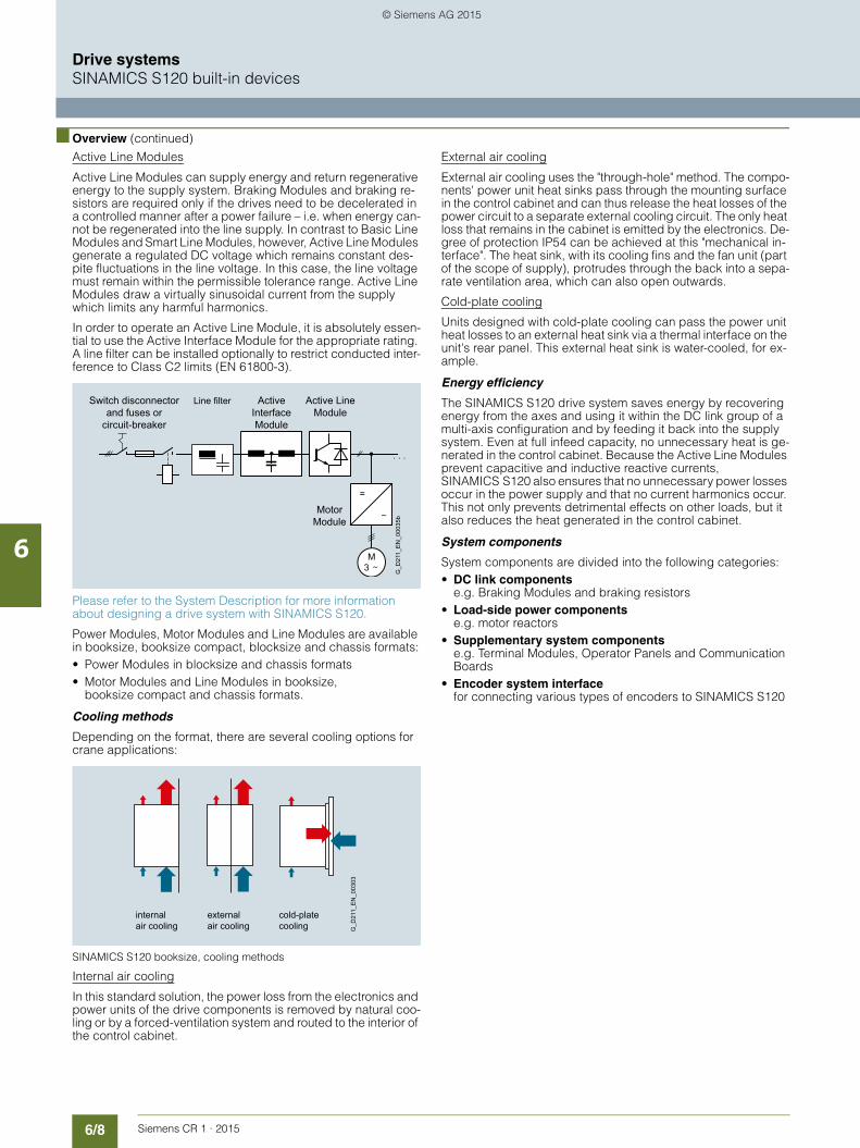
6/8 Siemens CR 1 · 2015
6
■ Overview (continued)
Drive systemsSINAMICS S120 built-in devices
Active Line Modules
Active Line Modules can supply energy and return regenerative energy to the supply system. Braking Modules and braking re-sistors are required only if the drives need to be decelerated in a controlled manner after a power failure – i.e. when energy can-not be regenerated into the line supply. In contrast to Basic Line Modules and Smart Line Modules, however, Active Line Modules generate a regulated DC voltage which remains constant des-pite fluctuations in the line voltage. In this case, the line voltage must remain within the permissible tolerance range. Active Line Modules draw a virtually sinusoidal current from the supply which limits any harmful harmonics.
In order to operate an Active Line Module, it is absolutely essen-tial to use the Active Interface Module for the appropriate rating. A line filter can be installed optionally to restrict conducted inter-ference to Class C2 limits (EN 61800-3).
Please refer to the System Description for more information about designing a drive system with SINAMICS S120.
Power Modules, Motor Modules and Line Modules are available in booksize, booksize compact, blocksize and chassis formats:• Power Modules in blocksize and chassis formats• Motor Modules and Line Modules in booksize,
booksize compact and chassis formats.
Cooling methods
Depending on the format, there are several cooling options for crane applications:
SINAMICS S120 booksize, cooling methods
Internal air cooling
In this standard solution, the power loss from the electronics and power units of the drive components is removed by natural coo-ling or by a forced-ventilation system and routed to the interior of the control cabinet.
External air cooling
External air cooling uses the "through-hole" method. The compo-nents' power unit heat sinks pass through the mounting surface in the control cabinet and can thus release the heat losses of the power circuit to a separate external cooling circuit. The only heat loss that remains in the cabinet is emitted by the electronics. De-gree of protection IP54 can be achieved at this "mechanical in-terface". The heat sink, with its cooling fins and the fan unit (part of the scope of supply), protrudes through the back into a sepa-rate ventilation area, which can also open outwards.
Cold-plate cooling
Units designed with cold-plate cooling can pass the power unit heat losses to an external heat sink via a thermal interface on the unit's rear panel. This external heat sink is water-cooled, for ex-ample.
Energy efficiency
The SINAMICS S120 drive system saves energy by recovering energy from the axes and using it within the DC link group of a multi-axis configuration and by feeding it back into the supply system. Even at full infeed capacity, no unnecessary heat is ge-nerated in the control cabinet. Because the Active Line Modules prevent capacitive and inductive reactive currents, SINAMICS S120 also ensures that no unnecessary power losses occur in the power supply and that no current harmonics occur. This not only prevents detrimental effects on other loads, but it also reduces the heat generated in the control cabinet.
System components
System components are divided into the following categories:• DC link components
e.g. Braking Modules and braking resistors• Load-side power components
e.g. motor reactors• Supplementary system components
e.g. Terminal Modules, Operator Panels and Communication Boards
• Encoder system interfacefor connecting various types of encoders to SINAMICS S120
. . .
MotorModule
Active InterfaceModule
Active LineModule
Switch disconnectorand fuses or
circuit-breaker
G_D
211_
EN
_000
35b
Line filter
M3
=
internalair cooling
externalair cooling
cold-plate cooling G
_D21
1_E
N_0
0303
© Siemens AG 2015

6/9Siemens CR 1 · 2015
6
■ Overview (continued)
Drive systemsSINAMICS S120 built-in devices
Booksize format
Booksize format units are optimized for multi-axis applications and are mounted adjacent to one another. The connection for the shared voltage-source DC link is an integral feature. The book-size format offers the full range of cooling options for crane ap-plications: internal air cooling, external air cooling and cold plate cooling.
Booksize compact format
Derived from the booksize format we developed the booksize compact format for machines with particularly high requirements for the compactness of their drives. The booksize compact for-mat combines all benefits of the booksize format and provides the same performance with an even smaller overall height and an extended overload capability. The booksize compact format is thus particularly well suitable for integration into machines with high dynamic requirements and confined installation conditions.
The booksize compact format has the same design for the cooling methods of internal air cooling and cold plate cooling.
Blocksize format
Blocksize format units are optimized for single-axis applications and are supplied only as Power Modules.
The CU310-2 Control Unit can be snapped onto them directly. The units are cooled by internal air cooling or liquid cooling.
Chassis format
Higher-output units (approximately 100 kW (150 hp) and above) are constructed in chassis format. These are available as Line Modules, Power Modules and Motor Modules. Chassis format units are cooled by an internal air cooling circuit. The CU310-2 Control Unit can be integrated in the Power Modules.
© Siemens AG 2015

6/10 Siemens CR 1 · 2015
6
Drive systemsSINAMICS S120 built-in devices
General technical specifications
■ Technical specifications
Unless specified otherwise, the following technical specifica-tions are valid for all the following components of the SINAMICS S120 drive system.
■ More information
For satisfactory and reliable operation of the drive system, original components of the SINAMICS system and the original Siemens accessories as described in this Catalog and the Configuration Manuals, in the functional descriptions or user manuals should be used.
The user must observe the configuring instructions.
Combinations that differ from the configuring instructions (also in conjunction with non-Siemens products) require a special agreement.
If no original components are used, for example, for repairs, ap-provals such as UL, EN and Safety Integrated can become inva-lid and thus the operation authorization for the machine with the non-Siemens components installed becomes invalid.
All of the approvals, certificates, declarations of conformity, test certificates, e.g. CE, UL, Safety Integrated etc. have been per-formed with the associated system components as they are de-scribed in the Catalogs and Configuration Manuals. The certifi-cates are only valid if the products are used with the described system components, are installed according to the Installation Guidelines and are used for their intended purpose. In other ca-ses, the vendor of these products is responsible for arranging that new certificates are issued.
Please refer to Catalog PM21 Chapter System description – Dimensioning for more engineering guidance to design a drive system with SINAMICS S120.
Note:
The products described in this catalog may cause high-fre-quency disturbances in a residential environment and necessi-tate the implementation of interference-suppression measures.
Electronics power supply 24 V DC, -15 %/+20 %
Vibratory load• Transport 1) acc. to EN 60721-3-2
- All units and components except for chassis format
Class 2M3
- Chassis format units Class 2M2• Operation
Test values acc. to EN 60068-2-6 Test Fc
10 ... 58 Hz: Constant deflection 0.075 mm
58 ... 150 Hz: Constant acceleration = 9.81 m/s2 (1 × g)
Shock stressing• Transport 1) acc. to EN 60721-3-2
- All units and components except for chassis format
Class 2M3
- Chassis format units Class 2M2• Operation
Test values acc. to EN 60068-2-27 Test Ea- Booksize and blocksize formats
FSA to FSC147 m/s2 (15 x g)/11 ms
- Blocksize format FSD to FSF 49 m/s2 (5 × g)/30 ms- Chassis format 98 m/s2 (10 × g)/20 ms
Ambient conditions• Protection class according to
EN 61800-5-1Class I (with protective conductor system) and Class III (PELV)
• Touch protection DIN VDE 0106 Part 100 and BGV A 3 when used properly
• Type of cooling Internal/external air cooling, power units with forced air cooling by means of built-in fan
Permissible ambient/coolant temperature (air) during operation• For line-side components, Power
Modules, Line Modules and Motor Modules
0 ... 40 °C (32 ... 104 °F) without derating,> 40 ... 55 °C (104 ... 131 °F), see derating characteristics
• For Control Units, supplementary system components, DC link com-ponents, and Sensor Modules
0 … 55 °C (32 … 131 °F)up to 2000 m (6562 ft) above sea level
Climatic ambient conditions• Storage 1) acc. to EN 60721-3-1 Class 1K4
Temperature -25 ... +70 °C (-77 ... +158 °F)
• Transport 1) acc. to EN 60721-3-2 Class 2K4Temperature -40 … +70 °C (-104 ... +158 °F)Max. air humidity 95 % at 40 °C (104 °F)
• Operation according to EN 60721-3-3
Class 3K3Temperature 0 ... 55 °C (32 ... 131 °F)Condensation, splashwater, and ice formation are not permitted (EN 60204, Part 1)
Environmental class/harmful chemical substances• Storage 1) acc. to EN 60721-3-1 Class 1C2• Transport 1) acc. to EN 60721-3-2 Class 2C2• Operation according to
EN 60721-3-3Class 3C2
Organic/biological influences• Storage 1) acc. to EN 60721-3-1 Class 1B1• Transport 1) acc. to EN 60721-3-2 Class 2B1• Operation according to
EN 60721-3-3Class 3B1
Degree of contaminationAccording to EN 61800-5-1
2
European Standards
EN 954-1 Safety of machinery – safety-related parts of control systems Part 1: General design principles
EN 61508-1 Functional safety of electrical/electro-nic/programmable electronic safety-related systemsPart 1: General requirements
EN 50370-1 Electromagnetic compatibility (EMC) – Product family standard for machine tools Part 1: Radiated interference
EN 55011 Industrial, scientific and medical high-frequency devices (ISM devices) – radio interference – limit values and measuring techniques
EN 60204-1 Electrical equipment of machinesPart 1: General definitions
EN 61800-3 Variable-speed electric drives Part 3: EMC product standard inclu-ding specific test methods
EN 61800-5-1 Adjustable-speed electrical power drive systemsPart 5: Safety requirementsMain section 1: Electrical and thermal requirements
North American standards
UL508C Power Conversion Equipment
CSA C22.2 No. 14 Industrial Control Equipment
Approvals
cULus Testing by UL (Underwriters Labora-tories, http://www.ul.com) according to UL and CSA standards
1) In transport packaging.
© Siemens AG 2015

6/11Siemens CR 1 · 2015
6
Drive systemsSINAMICS S120 built-in devices
Control Units
■ Overview
Innovative system architecture with a central Control Unit
Electronically coordinated single drives work together to per-form your drive tasks. Higher-level controllers operate the drives to achieve the required coordinated movement. This requires cyclic data exchange between the controller and the drives. This exchange usually took place via a field bus, which required a great deal of time and effort for installation and configuration. SINAMICS S120 takes a different approach: A central Control Unit controls the drives for all connected axes and also establi-shes the technological links between the drives and/or axes. Since all the required data is stored in the central Control Unit, it does not need to be transferred. Inter-axis connections can be established within a Control Unit and easily configured in the STARTER commissioning tool using a mouse.• Simple technological tasks can be carried out automatically
by the SINAMICS S120 Control Unit• The CU310-2 DP or CU310-2 PN Control Unit are available for
single drives• The CU320-2 Control Unit is designed for multi-axis applica-
tions• Sophisticated Motion Control tasks can be implemented with
the support of the more powerful D410-2, D425-2, D435-2, D445-2 and D455-2 Control Units of SIMOTION D (graded according to performance)
Each of these Control Units is based on an object-oriented
SINAMICS S120 standard firmware which contains all of the most popular control modes and can be scaled to meet even the most advanced performance requirements.
The drive controls are supplied as ready-to-configure drive objects:• Infeed Control for line infeed,• Vector Control for the broad scope of rugged asynchronous
(induction) motor applications• Servo Control for permanent-field synchronous motors with
demanding dynamic requirements• V/f control modes for simple applications such as group drives
with SIEMOSYN motors
Drive objects
A drive object is a self-contained software function with its own parameters and, if necessary, its own fault messages and alarms.
Extended technology with SIMOTION
SIMOTION D Control Units support the coordinated Motion Con-trol of multiple drives. Technology objects are implemented in addition to drive objects on these Control Units. These are grou-ped to form technology packages and make available extended Motion Control functions (e.g. synchronous operation, cam disk, path interpolation and others) or technological functions (e.g. a cam controller, a temperature or pressure control). The IEC 61131-3-compliant PLC integrated in SIMOTION D Control Units means that they are not just capable of controlling sequences of motions, but the entire machine including HMI and I/Os.
Comprehensive package of open-loop and closed-loop control functions
A wide variety of standard functions such as setpoint input, data set changeover, controller optimization and kinetic buffering en-sure a high degree of functional reliability and excellent flexibility of application.
G_D
211_
EN
_000
57a
Infeedcontrol
Drivecontrol
Drivecontrol
TerminalModule
evaluation
TerminalModule
evaluation
OptionBoard
evaluation
On-boardI/O
evaluation
Drive objectsControl Unit
TerminalModule
TerminalModule
MotorModule
MotorModule
LineModule
OptionBoard
......
© Siemens AG 2015
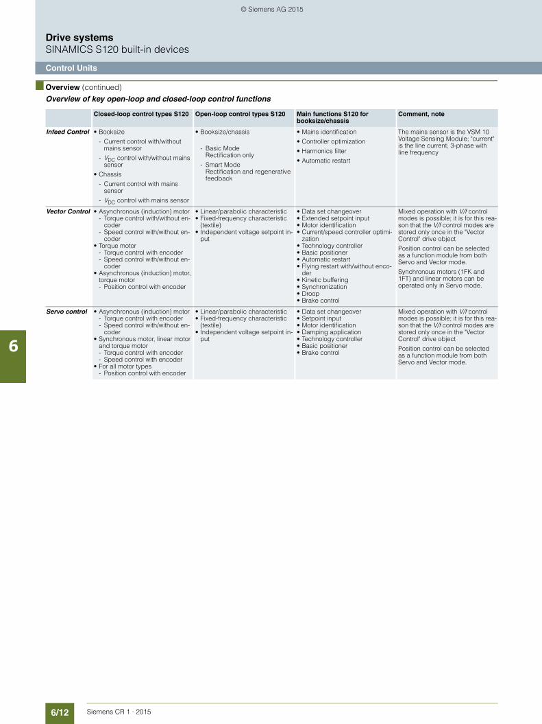
6/12 Siemens CR 1 · 2015
6
■ Overview (continued)
Drive systemsSINAMICS S120 built-in devices
Control Units
Overview of key open-loop and closed-loop control functions
Closed-loop control types S120 Open-loop control types S120 Main functions S120 for booksize/chassis
Comment, note
Infeed Control • Booksize
- Current control with/without mains sensor
- VDC control with/without mains sensor
• Chassis
- Current control with mains sensor
- VDC control with mains sensor
• Booksize/chassis
- Basic ModeRectification only
- Smart ModeRectification and regenerative feedback
• Mains identification
• Controller optimization
• Harmonics filter
• Automatic restart
The mains sensor is the VSM 10 Voltage Sensing Module; "current" is the line current; 3-phase with line frequency
Vector Control • Asynchronous (induction) motor- Torque control with/without en-
coder- Speed control with/without en-
coder• Torque motor
- Torque control with encoder- Speed control with/without en-
coder• Asynchronous (induction) motor,
torque motor- Position control with encoder
• Linear/parabolic characteristic• Fixed-frequency characteristic
(textile)• Independent voltage setpoint in-
put
• Data set changeover• Extended setpoint input• Motor identification• Current/speed controller optimi-
zation• Technology controller• Basic positioner• Automatic restart• Flying restart with/without enco-
der• Kinetic buffering• Synchronization• Droop• Brake control
Mixed operation with V/f control modes is possible; it is for this rea-son that the V/f control modes are stored only once in the "Vector Control" drive object
Position control can be selected as a function module from both Servo and Vector mode.
Synchronous motors (1FK and 1FT) and linear motors can be operated only in Servo mode.
Servo control • Asynchronous (induction) motor- Torque control with encoder- Speed control with/without en-
coder• Synchronous motor, linear motor
and torque motor- Torque control with encoder- Speed control with encoder
• For all motor types- Position control with encoder
• Linear/parabolic characteristic• Fixed-frequency characteristic
(textile)• Independent voltage setpoint in-
put
• Data set changeover• Setpoint input• Motor identification• Damping application• Technology controller• Basic positioner• Brake control
Mixed operation with V/f control modes is possible; it is for this rea-son that the V/f control modes are stored only once in the "Vector Control" drive object
Position control can be selected as a function module from both Servo and Vector mode.
© Siemens AG 2015

6/13Siemens CR 1 · 2015
6
■ Overview (continued)
Drive systemsSINAMICS S120 built-in devices
Control Units
BICO technology
Every drive object contains a large number of input and output variables which can be freely and independently interconnected using Binector Connector Technology (BICO). A binector is a lo-gic signal which can assume the value 0 or 1. A connector is a numerical value, e.g. the actual speed or current setpoint.
Drive Control Chart (DCC)
DCC Drive Control Chart for SINAMICS S120 for simple, graphi-cal configuration of control, logic and calculation functions at the drive level.
It expands the possibilities for easy configuring of technology functions for the SIMOTION Motion Control system as well as for the SINAMICS S120 drive system.
The user-friendly DCC editor supports easy graphical configura-tion and a clear presentation of control loop structures.
The associated block library contains a large choice of closed-loop control, calculation and logic modules as well as more com-plex open-loop and closed-loop control functions.
Drive Control Chart for SINAMICS S120 therefore provides a convenient basis for resolving drive-level open-loop and closed-loop control tasks directly in the converter.
Function module
The basic positioner EPos can be called on all SINAMICS S120 Control Units as an additionally activatable function module. The basic positioner can be used to resolve basic Motion Control tasks without additional external technological outlay from the drive itself.
The Technology controller is designed as a PID controller. It is suitable for implementing controls for regulating variables such as fill level, temperature, tension, pressure, flow rate and dancer position.
Integral safety functions (Safety Integrated)
The Control Units support comprehensive safety functions.
The integrated safety functions are the Safety Integrated Basic Functions• STO = Safe Torque Off• SBC= Safe Brake Control• SS1 = Safe Stop 1
and the Safety Integrated Extended Functions that require a license• SS2 = Safe Stop 2• SOS= Safe Operating Stop• SLS = Safely-Limited Speed• SSM= Safe Speed Monitor• SDI = Safe Direction• SLP = Safely-Limited Position
(abbreviations in accordance with IEC 61800-5-2)
If the extended integrated safety functions are used, licenses, supplementary system components such as TM54F terminal modules, or suitable safety controls will be necessary.For further information information about Safety Integrated visit:http://www.siemens.com/safety-integrated
CompactFlash card
The functions of the SINAMICS S120 drives are stored on a CompactFlash card. This card contains the firmware and para-meter settings for all drives in the form of a project. The Com-pactFlash card can also hold additional projects, which means that the correct project can be accessed immediately when se-ries machines of different types are commissioned. When the Control Unit has booted, the data on the CompactFlash card are read and loaded to the RAM.
The firmware is organized in objects. Drive objects are used to implement open-loop and closed-loop control functions for Line Modules, Motor Modules, Power Modules and other system components connected by DRIVE-CLiQ.
Diagnostics optimally supported by trace function
The time characteristics of input and output variables associated with drive objects can be measured by the integrated trace func-tion and displayed using the STARTER commissioning tool. The trace can record up to 4 signals simultaneously. A recording can be triggered dependent on freely selectable boundary condi-tions, e.g. the value of an input or output variable.
© Siemens AG 2015

6/14 Siemens CR 1 · 2015
6
Drive systemsSINAMICS S120 built-in devices
CU310-2 Control Units for single-axis drives
■ Overview
CU310-2 PN and CU310-2 DP Control Units
The CU310-2 Control Unit that is designed for the communica-tion and open-loop/closed-loop control functions of a SINAMICS S120 (AC/AC) is combined with the PM340 Power Module to create a powerful single-axis drive. PROFINET (PN) and PROFIBUS (DP) variants are available for fieldbus commu-nication.
CompactFlash Card for CU310-2 Control Units
The CompactFlash card contains the firmware and parameter settings. The CompactFlash card is plugged into the appropri-ate slot on the CU310-2 Control Unit.
A CU310-2 Control Unit can perform the communication, open-loop and closed-loop control functions for one Power Module. The performance expansion is not required in this case.
In addition to the firmware, the CompactFlash card also contains licensing codes which are required to enable firmware options.
Currently, the following firmware options can be ordered in addi-tion to the article number:• Safety Integrated Extended Functions, order code F01• High output frequency 1), order code J01• DCB Extension, order code U01
The firmware option can also be enabled on-site, for example, if the Safety Integrated Extended functions should be enabled later. You will need the serial number of the CompactFlash card and the Article No. of the firmware option to be enabled. With this information, you can purchase the associated license code from a license database and enable the firmware option. The license code is only valid for the CompactFlash card declared and can-not be transferred to other CompactFlash cards.
■ Design
The CU310-2 Control Unit features the following connections and interfaces as standard:• Fieldbus interface
- CU310-2 PN: 1 PROFINET interface with 2 ports (RJ45 sockets) with PROFIdrive V4 profile
- CU310-2 DP: 1 PROFIBUS interface with PROFIdrive V4 profile
• 1 DRIVE-CLiQ socket for communication with the DRIVE-CLiQ motor or other DRIVE-CLiQ devices (e.g. Sensor Modules or Terminal Modules)
• 1 encoder evaluation for evaluating the following encoder signals- Incremental encoder TTL/HTL- SSI encoder without incremental signals
• 1 PE/protective conductor connection• 1 connection for the electronics power supply via the 24 V DC
power supply connector• 1 temperature sensor input (KTY84-130 or PTC)• 3 parameterizable, fail-safe (can be used with firmware ver-
sion 4.5 and higher) digital inputs (isolated) or alternatively 6 parameterizable digital inputs (isolated).The fail-safe digital inputs can be routed, i.e. they can be routed via PROFIsafe to a higher-level controller.
• 5 parameterizable digital inputs (isolated)• 1 parameterizable, fail-safe (can be used with firmware ver-
sion 4.5 and higher) digital output (floating) or alternatively 1 digital output (floating) 2)
• 8 parameterizable bidirectional digital inputs/outputs (non-floating) 2)
• 1 analog input, either ± 10 V (resolution 12 bit + sign) or ± 20 mA (11 bit + sign)
• 1 Ethernet interface (socket RJ45) for commissioning and di-agnostics
• 1 slot for the CompactFlash card on which firmware and para-meters are stored
• 1 PM-IF interface for communication with the Power Modules in blocksize format
• 3 test sockets and one reference ground for commissioning support
• 1 interface to the BOP20 Basic Operator Panel
The status of the CU310-2 Control Unit is indicated via multi-co-lor LEDs.
A BOP20 Basic Operator Panel can also be snapped directly onto the CU310-2 Control Unit for diagnostic purposes, for ex-ample.
As the firmware and parameter settings are stored on a plug-in CompactFlash card, the Control Unit can be changed without the need for software tools.
1) For more information, visit http://support.automation.siemens.com/WW/view/en/104020669
2) In order to use the digital outputs, a 24 V supply voltage must be connec-ted to terminal X124.
© Siemens AG 2015
6/15Siemens CR 1 · 2015
6
Drive systemsSINAMICS S120 built-in devices
CU310-2 Control Units for single-axis drives
■ Integration
The CU310-2 Control Unit controls Power Modules in blocksize format via the PM-IF interface. DRIVE-CLiQ motors as well as Sensor Modules (SMC) can be connected to the integrated DRIVE-CLiQ socket to permit the operation of motors without a DRIVE-CLiQ interface.
With the BOP20 Basic Operator Panel, parameters can be chan-ged directly on the device. The BOP20 Basic Operator Panel can also be snapped onto the CU310-2 Control Unit during ope-ration to perform troubleshooting procedures.
The CU310-2 Control Unit and other connected components are commissioned and diagnosed with the STARTER commissio-ning tool. The CU310-2 Control Unit requires a CompactFlash card with firmware version V4.4 or higher.
A CU310-2 PN Control Unit communicates with the higher-level control system using PROFINET IO and the PROFIdrive V4 pro-file.
The SINAMICS S120 drive system with the CU310-2 PN Control Unit then assumes the function of a PROFINET IO device and can perform the following functions:• PROFINET IO device• 100 Mbit/s full duplex• Supports real-time classes of PROFINET IO:
- RT (Real-Time)- IRT (Isochronous Real-Time), minimum send cycle 500 μs
• Connects to controls as PROFINET IO devices using PROFId-rive compliant with Specification V4
• Standard TCP/IP communication for engineering processes with the STARTER commissioning tool and for accessing the integrated web server
• Integrated 2-port switch with two RJ45 sockets based on the ERTEC ASIC. The optimum topology (line, star, tree) can there-fore be configured without additional external switches.
A 24 V supply voltage must be connected to terminal X124 for the digital outputs to be used. A CompactFlash card with firm-ware V4.4 or higher is essential for the operation of the CU310-2 Control Unit.
© Siemens AG 2015

6/16 Siemens CR 1 · 2015
6
■ Integration (continued)
Drive systemsSINAMICS S120 built-in devices
CU310-2 Control Units for single-axis drives
Connection example of the CU310-2 Control Unit
Enc
oder
inte
rfaceserial interface
DR
IVE
-CLi
Q s
ocke
t 0
Memory card
G_D
211_
EN
_002
78a
24 Vext.
24 Vext.
24 Vext.
1) Motor temperature sensor input must be shielded.2) Inversion can be parameterized.3) Jumper open, isolation for digital inputs (DI).4) High-speed inputs must be shielded.5) Analog input must be shielded.6) Safety-related control with current sourcing and current sinking outputs.7) Safety-related control with two current sourcing outputs.8) In order to use the digital outputs, an external 24 V power supply must be connected to terminal X124.
Curr. sinking
Curr. sourcingCurr. sourcing
Curr. sourcing
24 V1 F-DO 0
F-DI 2
9
10
11
12
8
7
1
7)
6)
8)
2
3
4
5
± 10 V
DI 0
DI 1
DI 2
DI 3
9
10
11
12
8
7
1
2
3
4
5
DI 0
DI 2
DI 1
4)
4)
4)
4)
2)
2)
2)
3)
DI/DO 11
DI/DO 10
DI/DO 9
DI/DO 824 V
24 V
DI 3
M
M
M
M2
4)
4)
4)
4)
5)
6)
6)
DI/DO 15
DI/DO 14
DI/DO 13
DI/DO 12
M
M
AI 0+
AI 0- 8
6
5
1
2
3
7
4
DI 22
DO 16-
DO 16+
24 V1
M1
M2
M
DI 22-
DI 22+
8
6
5
1
2
3
7
4
F-DI 1
F-DI 0
DI 16
M1
DI 17+
DI 17-
DI 18
M1
M1
M1 DI 19-
DI 19+
DI 20
DI 21-
DI 21+
M
+
M
+
M
X124
M
24 V
M24 V
X22
24 V2 M2
24 V1
24 V1
24 V1
24 V1
M1
M1
M1
M
TxD
RxD
+
M
PROFIBUSX21
X150 P1 X150 P2X100
Control UnitCU310-2
X131X130
X232 3 5
-Temp 1)
+Temp 1)
6
X121
6
X120
PROFINET
X127
LAN
© Siemens AG 2015

6/17Siemens CR 1 · 2015
6
Drive systemsSINAMICS S120 built-in devices
CU310-2 Control Units for single-axis drives
■ Technical specifications
CU310-2 Control UnitPROFINET: 6SL3040-1LA01-0AA0PROFIBUS: 6SL3040-1LA00-0AA0
Power requirement, max.
At 24 V DC,without taking account of digital outputs and DRIVE-CLiQ supply
0.35 A for CU310-2 + 0.5 A for PM340 Power Module
Conductor cross-section, max. 2.5 mm2
Fuse protection, max. 20 A
Digital inputs In accordance with IEC 61131-2 Type 1
5 floating digital inputs
8 bidirectional non-floating digital inputs/digital outputs
3 parameterizable, fail-safe digital inputs (floating) or alternatively 6 parameterizable digital inputs (floa-ting)
5 bidirectional floating digital inputs/outputs
• Voltage -3 ... +30 V• Low level (an open digital input
is interpreted as "low")-3 ... +5 V
• High level 15 ... 30 V• Current consumption at 24 V DC,
typ.10 mA
• Delay time of digital inputs 1), ap-prox.- L → H 50 μs- H → L 100 μs
• Delay time of high-speed digital inputs 1), approx.(high-speed digital inputs can be used for position detection)- L → H 5 μs- H → L 50 μs
• Conductor cross-section, max. 1.5 mm2
Digital outputs(continuously short-circuit-proof)
8 bidirectional non-floating digital out-puts/digital inputs
• Voltage 24 V DC• Load current per digital output 2),
max.500 mA
• Delay time 1), typ./max.
- L → H 150 μs/400 μs- H → L 75 μs/100 μs
• Conductor cross-section, max. 1.5 mm2
Analog input The analog input can be switched bet-ween current input and voltage input
• As voltage input -10 ... +10 V; Ri > 100 kΩResolution: 12 bit + sign (with respect to the maximum range that can be resolved -11 ... +11 V)
• As current input -20 ... +20 mA; Ri > 250 ΩResolution: 11 bit + sign (based on -22 ... 22 mA)
Max. range that can be resolved: -44 ... +44 mA
Encoder evaluation • Incremental encoder TTL/HTL• SSI encoder without incremental sig-
nals• Input impedance
- TTL 570 Ω- HTL, max. 16 mA
• Encoder supply 24 V DC/0.35 A or 5 V DC/0.35 A• Encoder frequency, max. 300 kHz• SSI baud rate 100 ... 250 kbaud• Resolution absolute position SSI 30 bit• Cable length, max.
- TTL encoder 100 m (328 ft)(only bipolar signals permitted) 3)
- HTL encoder 100 m (328 ft) for unipolar signals300 m (984 ft) for bipolar signals 3)
- SSI encoder 100 m (328 ft)
Power loss <20 W
PE connection M5 screw
Dimensions• Width 73 mm (2.87 in)• Height
- CU310-2 PN 191 mm (7.52 in)- CU310-2 DP 187 mm (7.36 in)
• Depth 75 mm (2.95 in)
Weight, approx. 0.95 kg (2.09 lb)
Approvals, according to cULus
CU310-2 Control UnitPROFINET: 6SL3040-1LA01-0AA0PROFIBUS: 6SL3040-1LA00-0AA0
1) The specified delay times refer to the hardware. The actual reaction time depends on the time slot in which the digital input or output is processed.
2) In order to use the digital outputs, an external 24 V power supply must be connected to terminal X124.
3) Signal cables twisted in pairs and shielded.
© Siemens AG 2015

6/18 Siemens CR 1 · 2015
6
Drive systemsSINAMICS S120 built-in devices
CU310-2 Control Units for single-axis drives
■ Selection and ordering data ■ More information
Firmware version
The firmware version is encoded as follows in the Article No. printed on the CompactFlash card:
Example:
A CompactFlash card with firmware version V4.7 and a safety license for a CU310-2 PN Control Unit are required:Article No.: 6SL3054-0EH00-1BA0-ZF01
Description Article No.
CU310-2 PN Control Unit
Without CompactFlash card
6SL3040-1LA01-0AA0
CU310-2 DP Control Unit
Without CompactFlash card
6SL3040-1LA00-0AA0
CompactFlash Card for Control Units CU310-2 PN, CU310-2 DPWith firmware V4.7 incl. Certificate of Licence
6SL3054-0EH00-1BA0
• and with Safety license 6SL3054-0EH00-1BA0-ZF01
• and with high output frequency 1) 6SL3054-0EH00-1BA0-ZJ01
• and with DCB Extension license (firmware V4.6 and higher)(further information about DCB Ex-tension and license upgrades can be found under Drive Control Chart (DCC))
6SL3054-0EH00-1BA0-ZU01
License upgrades• High output frequency 1)
Option high output frequency for ac-tivating output frequencies above 550 Hz for upgrading the license of a CompactFlash card
6SL3074-0AA02-0AA0
• Safety license Option Safety Integrated Extended Functions incl. Certificate of Licence for one axis for upgrading the licen-se of a CompactFlash card
6SL3074-0AA10-0AA0
Accessories
Basic Operator Panel BOP20 6SL3055-0AA00-4BA0
STARTER commissioning tool 2)
On DVD-ROM
6SL3072-0AA00-0AG0
Accessories for re-ordering
SINAMICS/SINUMERIK/SIMOTION dust-proof blanking plugs(50 units)
For DRIVE-CLiQ port
6SL3066-4CA00-0AA0
Description Article No.
CompactFlash card for CU310-2 PN and CU310-2 DPControl Units with saftey license
including Certificate of License and with saftey license
6SL3054-0E ■ 00-1BA0
• Firmware V4.4
• Firmware V4.5
• Firmware V4.6
• Firmware V4.7
E
F
G
H
1) For more information, visit http://support.automation.siemens.com/WW/view/en/104020669
2) The STARTER commissioning tool is also available on the Internet at http://support.automation.siemens.com/WW/view/en/10804985/133100
© Siemens AG 2015

6/19Siemens CR 1 · 2015
6
Drive systemsSINAMICS S120 built-in devices
CU320-2 Control Unit
■ Overview
The communication, open-loop and closed-loop control func-tions for one or more Motor Modules and the Line Module are executed in a CU320-2 Control Unit. The CU320-2 Control Unit is designed for multi-axis operation.
CU320-2 DP Control Unit with BOP20 Basic Operator Panel
CompactFlash card for CU320-2 Control Units
The CompactFlash card contains the firmware and parameter settings. The CompactFlash card is plugged into the appropri-ate slot on the CU320-2 Control Unit.
A CU320-2 Control Unit can perform the communication, open-loop and closed-loop control functions for several Motor Modules. The computing capacity required increases in propor-tion to the number of connected Motor Modules and system components and in relation to the dynamic response required. For the CU320-2 Control Unit, the performance expansion is necessary from the 4th axis. The utilization of the CU320-2 Control Unit can be calculated with the SIZER engineering tool.
In addition to the firmware, the CompactFlash Card also con-tains licensing codes which are required to enable firmware options.
In addition to the Article No., the following firmware options can currently be ordered with or without performance expansion:• Safety Integrated Extended Functions, order codes per axis
F01 to F06 (see Catalog PM 21, Chapter Safety Integrated)• High output frequency 1), order code J01• DCB Extension, order code U01
The firmware options can also be enabled on-site, for example, if the performance expansions required are not known at the time of placing the order or the Safety Integrated Extended Functions are to be enabled retrospectively. You will need the serial number of the CompactFlash card and the Article No. of the firmware option to be enabled. With this information, you can purchase the associated license code from a license database and enable the firmware option. The license code is only valid for the CompactFlash card declared and cannot be transferred to other CompactFlash cards.
1) For further information see http://support.automation.siemens.com/WW/view/en/104020669
© Siemens AG 2015

6/20 Siemens CR 1 · 2015
6
Drive systemsSINAMICS S120 built-in devices
CU320-2 Control Unit
■ Design
CU320-2 Control Units feature the following interfaces as standard:• 4 DRIVE-CLiQ sockets for communication with other
DRIVE-CLiQ devices, e.g. Motor Modules, Active Line Modules, Sensor Modules, Terminal Modules
• CU320-2 PN: 1 PROFINET interface with 2 ports (RJ45 sockets) with PROFIdrive V4 profile
• CU320-2 DP: 1 PROFIBUS interface with PROFIdrive V4 pro-file
• 12 parameterizable digital inputs (floating)• 8 parameterizable bidirectional digital inputs/digital outputs
(non-floating)• 1 serial RS232 interface• 1 interface for the BOP20 Basic Operator Panel• 1 slot for the CompactFlash card on which firmware and
parameters are stored• 1 slot for mounting an option module (e.g. TB30 Terminal
Board)• 2 rotary coding switches for manually setting the PROFIBUS
address• 1 Ethernet interface for commissioning and diagnostics• 3 test sockets and one reference ground for commissioning
support• 1 connection for the electronics power supply via the 24 V DC
power supply connector• 1 PE (protective earth) connection• 1 ground connection
A shield connection for the signal cable shield on the option mo-dule is located on the CU320-2 Control Unit.
The available option slot is used to expand the interfaces, for example, to include additional terminals or for communication purposes.
The status of the CU320-2 Control Unit is indicated via multi-co-lor LEDs.
As the firmware and parameter settings are stored on a plug-in CompactFlash card, the Control Unit can be changed without the need for software tools.
The CU320-2 Control Unit can be mounted on the side of the Line Module in booksize format via brackets integrated in a Line Module. The CU320-2 Control Unit can also be fixed to the wall of the control cabinet using the integrated fixing lugs. As the CU320-2 Control Unit is not as deep as the Line Modules, suit-able spacers are available to increase the depth of the CU320-2 Control Unit to 270 mm (10.6 in).
■ Integration
DRIVE-CLiQ components, for example, Motor Modules and Active Line Modules, can be connected to a CU320-2 Control Unit. The number of modules depends on the performance required, including duty type and additional functions.
The BOP20 Basic Operator Panel can also be snapped onto the CU320-2 Control Unit during operation to perform troubleshoo-ting procedures.
The CU320-2 Control Unit and other connected components are commissioned and diagnosed with the STARTER commissio-ning tool.
The CU320-2 PN Control Unit requires a CompactFlash card with firmware V4.4 or higher.The CU320-2 DP Control Unit requires a CompactFlash card with firmware V4.3 or higher.
© Siemens AG 2015

6/21Siemens CR 1 · 2015
6
■ Integration (continued)
Drive systemsSINAMICS S120 built-in devices
CU320-2 Control Unit
Connection example of a CU320-2 Control Unit
DR
IVE
-CLi
Q s
ocke
t 0
DR
IVE
-CLi
Q s
ocke
t 1
DR
IVE
-CLi
Q s
ocke
t 2
DR
IVE
-CLi
Q s
ocke
t 3
serial interface3) Can be parameterized individually as input/output.2) Jumper open, isolation for digital inputs (DI).1) High-speed inputs (must be shielded).
G_D
211_
EN
_002
85
ext.24 V
Test sockets
Control UnitCU320-2
X140
1)
1)
1)
M
+
M
+
M
X124
M
V + 24
M
M
DI/DO 11
DI/DO 10
DI/DO 9
14
13
12
11
10
9 DI/DO 8
8 M
M1 7
DI 16
DI 17
DI 3
3
4
5
6
X122
DI 2
2)
2 3 5
3)
3)
+
M
X126
PROFIBUS
X100 X101 X102 X103
M
MTxD
RxD
+
Opt
ion
boar
d
DI 1
1
2
DI 0
1)
M1
M1
M1
M1
M1
M1
1)
1)
1)
M
M
DI/DO 15
DI/DO 14
DI/DO 13
14
13
12
11
10
9 DI/DO 12
8 M
M2 7
DI 20
DI 21
DI 7
3
4
5
6
X132
DI 6
2)
DI 5
1
2
DI 4
1)
M2
M2
M2
M2
M2
M2
M T2
T1 T0
X150 P2
X150 P1
X127
PROFINET
PROFINET
LAN
© Siemens AG 2015

6/22 Siemens CR 1 · 2015
6
Drive systemsSINAMICS S120 built-in devices
CU320-2 Control Unit
■ Technical specifications ■ Selection and ordering data
CU320-2 DP Control Unit
PROFINET: 6SL3040-1MA01-0AA0PROFIBUS: 6SL3040-1MA00-0AA0
Power requirement, max.
At 24 V DC,without taking account of digital outputs, expansion option slot and DRIVE-CLiQ supply
1.0 A
Conductor cross-section, max. 2.5 mm2
Fuse protection, max. 20 A
Digital inputs In accordance with IEC 61131 2 type 112 floating digital inputs8 bidirectional non-floating digital inputs/digital outputs
• Voltage -3 … +30 V• Low level (an open digital input is inter-
preted as "low")-3 … +5 V
• High level 15 … 30 V• Current consumption at 24 V DC, typ. 9 mA• Delay time of digital inputs 1), approx.
- L → H 5 μs- H → L 50 μs
• Conductor cross-section, max. 1.5 mm2
Digital outputs
(sustained short-circuit strength)
8 bidirectional non-floating digital outputs/digital inputs
• Voltage 24 V DC• Load current per digital output, max. 500 mA• Delay time 1), typ./max.
- L → H 150 μs/400 μs- H → L 75 μs/100 μs
• Conductor cross-section, max. 1.5 mm2
Power loss 24 W
PE connection M5 screw
Ground connection M5 screw
Dimensions• Width 50 mm (1.97 in)• Height 300 mm (11.8 in)• Depth 226 mm (8.90 in)
Weight, approx. 2.3 kg (5 lb)
Approvals, according to cULus
1) The specified delay times refer to the hardware. The actual reaction time depends on the time slice in which the digital input or output is processed.
2) The specified delay times refer to the hardware. The actual reaction time depends on the time slice in which the digital input or output is proces-sedFor further information see http://support.automation.siemens.com/WW/view/en/104020669
Description Order No.
CU320-2 PN Control Unit
Without CompactFlash card
6SL3040-1MA01-0AA0
CU320-2 DP Control Unit
Without CompactFlash card
6SL3040 1MA00 0AA0
CompactFlash card for CU320-2 Control Unit without Safety license
- Without performance expansion 6SL3054-0E ■ 00-1BA0- With performance expansion
firmware option6SL3054-0E ■ 01-1BA0
CompactFlash card for CU320-2 Control Unit with Safety license
• For 1 axis- Without performance expansion 6SL3054-0E
F01■ 00-1BA0-Z
- With performance expansion firmware option
6SL3054-0EF01
■ 01-1BA0-Z
• For 2 axes- Without performance expansion 6SL3054-0E
F02■ 00-1BA0-Z
- With performance expansion firmware option
6SL3054-0EF02
■ 01-1BA0-Z
• For 3 axes- Without performance expansion 6SL3054-0E
F03■ 00-1BA0-Z
- With performance expansion firmware option
6SL3054-0EF03
■ 01-1BA0-Z
• For 4 axes- With performance expansion
firmware option6SL3054-0EF04
■ 01-1BA0-Z
• For 5 axes- With performance expansion
firmware option6SL3054-0EF05
■ 01-1BA0-Z
• For 6 axes- With performance expansion
firmware option6SL3054-0EF06
■ 01-1BA0-Z
• and with high output frequency 2) 6SL3054-0EJ01
■ 00-1BA0-Z
• and with DCB Extension license (firmware V4.6 and higher)(more information about DCB Exten-sion and license upgrades can be found under Drive Control Chart (DCC))
6SL3054-0EU01
■ 01-1BA0-Z
Firmware V4.4 EFirmware V4.5 FFirmware V4.6 GFirmware V4.7 H
Post-licensing• Performance expansion
Performance expansion option including Certificate of License for upgrading the license of a CompactFlash card
6SL3074-0AA01-0AA0
• High output frequency 2)
High output frequency option for enabling output frequencies above 550 Hz for upgrading the license of a CompactFlash card
6SL3074-0AA02-0AA0
• Safety licenseSafety Integrated Extended Functions option including Certificate of License for one axis for upgrading the license of a CompactFlash card. This option should be ordered once for each axis, max. 6 × for a CompactFlash card
6SL3074-0AA10-0AA0
© Siemens AG 2015
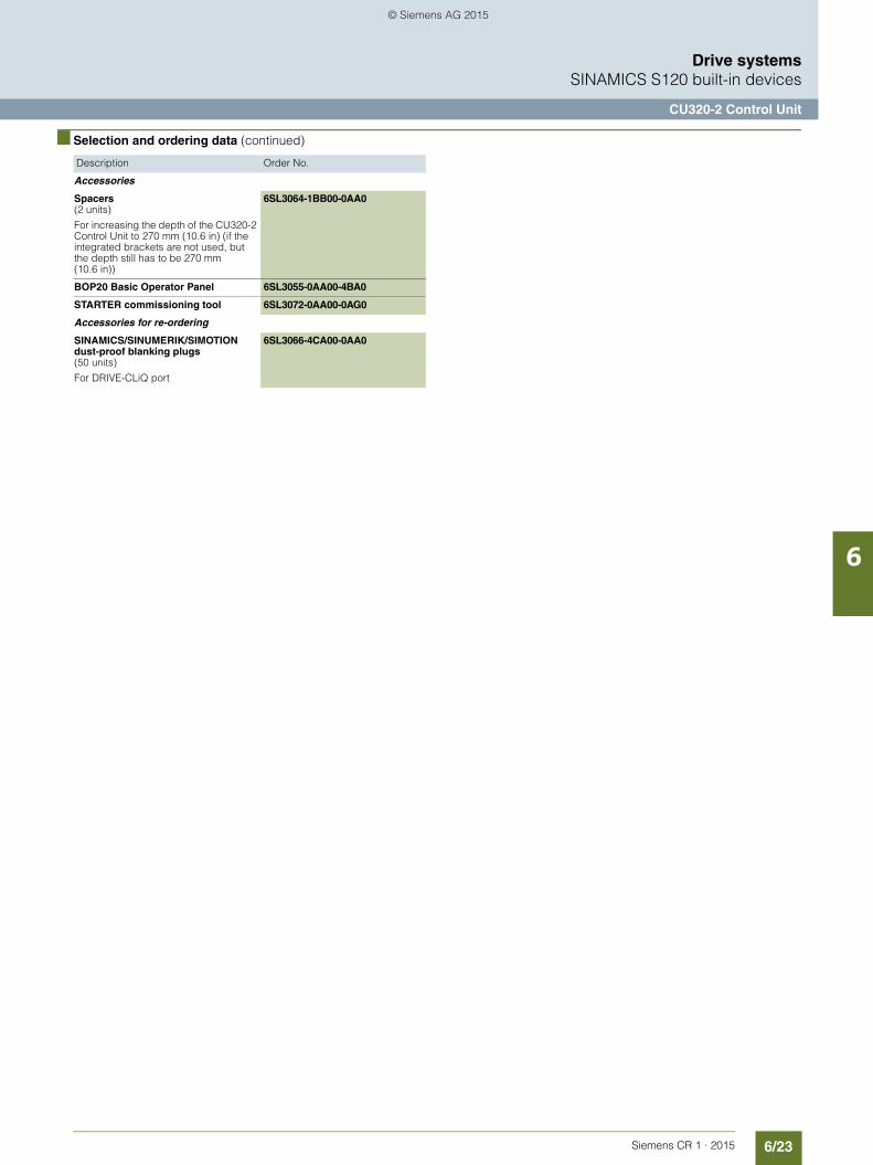
6/23Siemens CR 1 · 2015
6
■ Selection and ordering data (continued)
Drive systemsSINAMICS S120 built-in devices
CU320-2 Control Unit
Accessories
Spacers(2 units)
For increasing the depth of the CU320-2 Control Unit to 270 mm (10.6 in) (if the integrated brackets are not used, but the depth still has to be 270 mm (10.6 in))
6SL3064-1BB00-0AA0
BOP20 Basic Operator Panel 6SL3055-0AA00-4BA0
STARTER commissioning tool 6SL3072-0AA00-0AG0
Accessories for re-ordering
SINAMICS/SINUMERIK/SIMOTIONdust-proof blanking plugs(50 units)
For DRIVE-CLiQ port
6SL3066-4CA00-0AA0
Description Order No.
© Siemens AG 2015

6/24 Siemens CR 1 · 2015
6
Drive systemsSINAMICS S120 built-in devices
STARTER commissioning tool
■ Overview
The user-friendly STARTER commissioning tool can be used for:• Commissioning• Optimization• Diagnostics
This software can be operated as a standalone PC application, or integrated as a TIA-compatible program in SIMATIC STEP 7, or highly integrated into the SCOUT Engineering System (forSIMOTION). The basic functions and handling are the same in both cases.
In addition to the SINAMICS drives, STARTER also supports MICROMASTER 4 devices.
The project wizards can be used to create the drives within the structure of the project tree.
Beginners are supported by solution-based dialog guidance, whereby a standard graphics-based display maximizes clarity when setting the drive parameters.
First commissioning is guided by a wizard which makes all the basic settings in the drive. Therefore, getting a motor up and run-ning is merely a question of setting a few of the drive parameters as part of the drive configuration process.
The individual settings required are made using graphics-based parameterization screens, which also precisely visualize the principle of operation of the drive.
Examples of individual settings that can be made include:• How terminals are used• Bus interface• Setpoint channel (e.g., fixed setpoints)• Closed-loop speed control (e.g., ramp-function generator,
limits)• BICO interconnections• Diagnostics
For experts, the expert list can be used to specifically and quickly access individual parameters at any time. An individual compilation of frequently used parameters can be saved in de-dicated user lists and watch tables.
In addition, the following functions are available for optimization purposes:• Self-optimization of the controller settings (depending on drive
unit)• Setup and evaluation of trace recordings 1)
Tool function for recording 2 × 8 signals with• Measuring cursor function• Extensive trigger functions• Several Y scales• Sampling times in the current controller cycle clock
Diagnostics functions provide information about:• Control/status words• Parameter status• Operating conditions• Communication states
Performance features• User-friendly: Only a small number of settings need to be
made for successful first commissioning: The motor starts to rotate
• Solution-oriented dialog-based user guidance simplifies com-missioning
• Self-optimization functions reduce manual effort for optimiza-tion.
Minimum system requirements
The following minimum requirements must be complied with:• Hardware
- PG or PC with Pentium III min. 1 GHz (recommended >1 GHz)
- Work memory 1 GB (2 GB recommended)- Screen resolution 1024 × 768 pixels, 16-bit color depth- Free hard disk memory: min. 3 GB
• Software- Microsoft Internet Explorer V6.0 or higher- 32-bit operating systems:
Microsoft Windows XP Professional SP3Microsoft Windows 7 Professional incl. SP1Microsoft Windows 7 Ultimate incl. SP1Microsoft Windows 7 Enterprise incl. SP1 (standard installa-tion)
- 64-bit operating systems:Microsoft Windows 7 Professional SP1Microsoft Windows 7 Ultimate SP1Microsoft Windows 7 Enterprise SP1 (standard installation)Microsoft Windows Server 2008 R2 SP1
1) Depending on drive unit. Not supported for MICROMASTER 4, SINAMICS G110, SINAMICS G120 <firmware V4.4, SINAMICS G110D and SINAMICS G120D <firmware V4.5.
© Siemens AG 2015

6/25Siemens CR 1 · 2015
6
Drive systemsSINAMICS S120 built-in devices
STARTER commissioning tool
■ Integration
Data can be exchanged (depending on the version) via PROFIBUS or PROFINET/Ethernet or via a serial interface.
For commissioning and service, a PG/PC can be connected to the CU320-2 Control Unit via PROFIBUS. A PROFIBUS connec-tion must be available with a connecting cable at the PG/PC.
Further, communication between a CU320-2 Control Unit and PG/PC can also be established via Ethernet, either via an (optional) CBE20 Communication Board or the Ethernet inter-face -X127 on the CU320-2 Control Unit.
Note:
The terminal strip -X127 is suitable as a communication link to the PG/PC only for the purposes of servicing and commissio-ning.
■ Selection and ordering data
Note:
In addition to the STARTER commissioning tool, SINAMICS Drive Control Chart (SINAMICS DCC) can be installed. This allows the device functionality in the SINAMICS drive system to be expan-ded with technology functions as required.
More information about SINAMICS DCC can be found in section "SINAMICS Drive Control Chart (SINAMICS DCC)".
Accessories
Depending on the version of the Control Unit (CU), the Control Unit of the drive unit can communicate with the programming device (PG) or PC via PROFIBUS or PROFINET/Ethernet or via a serial interface. The following accessories are available for the particular drive system as listed in the following table.
■ More information
The STARTER commissioning tool is also available for update purposes on the Internet athttp://www.siemens.com/starter
Description Article No.STARTER commissioning tool
for SINAMICS and MICROMASTER
English, French, German, Italian, Spanish
6SL3072-0AA00-0AG0
Description Recommended accessories
For communication between the drive unit and the pro-gramming device or PCArticle No.
SINAMICS S120• RS232 SIMATIC S7 connecting
cable
Null modem cable, 6 m (19.69 ft)
6ES7901-1BF00-0XA0
• PROFIBUS CP 5711 communication module
USB adapter for connecting a PG or notebook to PROFI-BUS or MPI
USB cable (2 m/6.56 ft) inclu-ded in scope of supply
6GK1571-1AA00
SIMATIC DP plug-in cable
12 MBaud, for PG connec-tion, pre-assembled with 2 × 9-pin SUB D connector, 3 m (9.84 ft)
6ES7901-4BD00-0XA0
• PROFINET/Ethernet
Standard CAT5 Ethernet cable or PROFINET cable
–
© Siemens AG 2015

6/26 Siemens CR 1 · 2015
6
Drive systemsSINAMICS S120 built-in devices
SINAMICS Drive Control Chart (SINAMICS DCC)
■ Overview
SINAMICS Drive Control Chart (SINAMICS DCC) expands the scope of device functions by means of freely available closed-loop control, arithmetic and logic blocks and offers a means by which technological functions can be graphically configured in the SINAMICS drive system. SINAMICS DCC is the first stage of the Advanced Technology Function and is installed as an add-on to the STARTER commissioning tool.
SINAMICS DCC provides users with greater scope to adapt these systems to the specific functions of their machines. SINAMICS DCC does not limit the number of functions that can be used. The number of functions is limited only by the performance capability of the Control Unit.
SINAMICS DCC is available for the following SINAMICS drive systems:• SINAMICS G130• SINAMICS G150• SINAMICS S120• SINAMICS S150• SINAMICS DCM• SINAMICS GM150• SINAMICS SM150• SINAMICS GL150• SINAMICS SL150
The user-friendly DCC editor enables easy graphics-based con-figuration, allows control loop structures to be clearly represen-ted and provides a high degree of reusability of diagrams that have already been created.
The open-loop and closed-loop control functions are defined by using multi-instance-capable blocks (Drive Control Blocks (DCBs)) from a library (DCB library) that are selected and gra-phically linked with one another by dragging and dropping. Test and diagnostic functions allow the program behavior to be veri-fied and, in the case of a fault, the cause identified.
Two types of DCB library are available, i.e. DCB Standard and DCB Extension. The DCB Standard library supplied with SINAMICS DCC contains a large selection of closed-loop, arithmetic and logic blocks, as well as comprehensive open-loop and closed-loop control functions.
For logically combining, evaluating and acquiring binary sig-nals, all commonly used logic functions are available for selec-tion (AND, XOR, on/off delay, RS flipflop, counter, etc.). A wide range of arithmetic functions, such as absolute value generation, dividers and minimum/maximum evaluation are available to monitor and evaluate numerical quantities. In addition to the closed-loop drive control, axial winder functions, PI controllers, ramp-function generators or wobble generators are simple to configure.
In addition to the standard library, the DCB Extension library is also available with SINAMICS DCC, firmware version V4.6 and higher. This contains an extended range of blocks that can be used as an additional, independent library in the DCC Editor.
DCB Extension provides new motion control blocks as a GMC library.
Using these blocks, it is possible to implement the following positioning and synchronous operation functions with SINAMICS DCC:• Positioning• 1:1 synchronous operation• Gearing• Gearing and positioning• Camming
These applications are available for downloading from the Internet on the Siemens Application Support pages athttp://www.siemens.com/sinamics-applications
With the blocks provided by DCB Extension, it is also possible to commission the programming of user-specific blocks.
SINAMICS DCC provides a convenient basis for resolving drive-level open-loop and closed-loop control tasks directly in the con-verter. This further extends the possibility of adapting SINAMICS to the particular application. Local data processing in the drive supports the implementation of modular machine concepts and results in an increase in the overall machine performance.
Minimum hardware and software requirements
See STARTER commissioning tool.
© Siemens AG 2015

6/27Siemens CR 1 · 2015
6
Drive systemsSINAMICS S120 built-in devices
SINAMICS Drive Control Chart (SINAMICS DCC)
■ Selection and ordering data
SINAMICS DCC comprises the graphical configuring tool (DCC Editor) and the DCB standard library. SINAMICS DCC is installed as an add-on to the STARTER commissioning tool.
The necessary engineering license for each PC (floating) for SINAMICS DCC is acquired at the same time the order is placed. No runtime license is required for the DCB standard library inclu-ded in the scope of supply.
Existing licenses for SINAMICS DCC V2.1 and V2.2 SP1 are also valid for SINAMICS DCC V2.3.An upgrade variant for the engineering license is available for SINAMICS DCC V2.0.
The blocks of the DCB Extension library are also configured with the graphical configuring tool (DCC Editor). Use of these blocks requires a runtime license.
Description Article No.
SINAMICS DCC V2.3
for STARTER V4.4
Graphic configuring with SINAMICS DCC
DCC Editor + DCB standard library
• Single-user engineering license, with data carrier
6AU1810-1HA23-0XA0
• Upgrade engineering license, with data carrier
6AU1810-1HA23-0XE0
Description Article No.
SINAMICS DCB Extension license
Runtime license for license upgrading with firmware version V4.6 or higher(can also be ordered in conjunction with the CompactFlash card, see Compact-Flash card for CU310-2 and CU320-2 Control Units)
6SL3077-0AA00-0AB0
© Siemens AG 2015

6/28 Siemens CR 1 · 2015
6
Drive systemsSINAMICS S120 built-in devices
Air-cooled Power Modules in blocksize format
■ Design
PM340 Power Modules in blocksize format, frame sizes FSA to FSF
The PM340 Power Modules in blocksize format feature the following connections and interfaces as standard:• Line connection• PM-IF interface for connection of the PM340 Power Module
and CU310-2/SIMOTION D410-2 Control Unit or CUA31/CUA32 Control Unit Adapter. The PM340 Power Module also supplies power to the CU310-2/SIMOTION D410-2 Control Unit or CUA31/CUA32 Control Unit Adapter by means of an integrated power supply
• Terminals DCP/R1 and R2 for connection of an external braking resistor
• Motor connection made with screw-type terminals or screw studs
• Control circuit for the Safe Brake Relay for controlling a holding brake
• 2 PE (protective earth) connections
Power Modules without integrated line filter can be connected to grounded TN/TT and non-grounded IT systems. Power Modules with integrated line filter are suitable only for connection to TN systems with grounded star point.
The integrated Braking Unit (Braking Chopper) is rated with the capability to continuously utilize the external braking resistor. The temperature of the external braking resistor must be monito-red to provide protection against thermal overloading.
© Siemens AG 2015

6/29Siemens CR 1 · 2015
6
Drive systemsSINAMICS S120 built-in devices
Air-cooled Power Modules in blocksize format
■ Selection and ordering data
Accessories
For technical specifications, selection and ordering data for the associated line reactors, line filters and the recommended line-side components, see Catalog PM 21, Section 3 "Power Modules".
■ More information
For detailed technical information, see Catalog PM 21, Chapter 3 "Power Modules".
Rated output current Type rating Frame size Air-cooled PM340 Power Module in blocksize formatwithout line filter
Air-cooled PM340 Power Modulein blocksize formatwith integrated line filter
A kW (hp) Article No. Article No.Line voltage 200 ... 240 V 1 AC0.9 0.12 (0.2) FSA 6SL3210-1SB11-0UA0 6SL3210-1SB11-0AA02.3 0.37 (0.5) FSA 6SL3210-1SB12-3UA0 6SL3210-1SB12-3AA03.9 0.75 (0.75) FSA 6SL3210-1SB14-0UA0 6SL3210-1SB14-0AA0Line voltage 380 ... 480 V 3 AC1.3 0.37 (0.5) FSA 6SL3210-1SE11-3UA0 –1.7 0.55 (0.75) FSA 6SL3210-1SE11-7UA0 –2.2 0.75 (1) FSA 6SL3210-1SE12-2UA0 –3.1 1.1 (1.5) FSA 6SL3210-1SE13-1UA0 –4.1 1.5 (2) FSA 6SL3210-1SE14-1UA0 –5.9 2.2 (3) FSB 6SL3210-1SE16-0UA0 6SL3210-1SE16-0AA07.7 3 (5) FSB 6SL3210-1SE17-7UA0 6SL3210-1SE17-7AA010.2 4 (5) FSB 6SL3210-1SE21-0UA0 6SL3210-1SE21-0AA018 7.5 (10) FSC 6SL3210-1SE21-8UA0 6SL3210-1SE21-8AA025 11 (15) FSC 6SL3210-1SE22-5UA0 6SL3210-1SE22-5AA032 15 (20) FSC 6SL3210-1SE23-2UA0 6SL3210-1SE23-2AA038 18.5 (25) FSD 6SL3210-1SE23-8UA0 6SL3210-1SE23-8AA045 22 (30) FSD 6SL3210-1SE24-5UA0 6SL3210-1SE24-5AA060 30 (37) FSD 6SL3210-1SE26-0UA0 6SL3210-1SE26-0AA075 37 (50) FSE 6SL3210-1SE27-5UA0 6SL3210-1SE27-5AA090 45 (60) FSE 6SL3210-1SE31-0UA0 6SL3210-1SE31-0AA0110 55 (75) FSF 6SL3210-1SE31-1UA0 6SL3210-1SE31-1AA0145 75 (100) FSF 6SL3210-1SE31-5UA0 6SL3210-1SE31-5AA0178 90 (125) FSF 6SL3210-1SE31-8UA0 6SL3210-1SE31-8AA0
© Siemens AG 2015

6/30 Siemens CR 1 · 2015
6
Drive systemsSINAMICS S120 built-in devices
Air-cooled Power Modules in chassis format
■ Design
Power Module in chassis format with Control Unit (not included in scope of supply)
The Power Modules in chassis format feature the following connections and interfaces as standard:• 1 power connection• 2 DC link connections for options, e.g. Braking Modules• 3 DRIVE-CLiQ sockets• 1 safe standstill input (enable pulses)• 1 temperature sensor input (KTY84-130 or PTC/Pt100)• 1 electronics power supply connection• 1 motor connection• 1 connection for Safe Brake Adapter• 2 PE (protective earth) connections
The CU310-2/SIMOTION D410-2 Control Unit can be mounted in Power Modules of chassis format.
The scope of supply of the Power Modules includes:• 1 DRIVE-CLiQ cable
for connection to the CU310-2/SIMOTION D410-2 Control Unit• One 24 V supply cable
for connection to the CU310-2/SIMOTION D410-2 Control Unit• 1 mounting plate
for attaching the CU310-2/SIMOTION D410-2 Control Unit• 1 set of warning signs in 30 languages
Power Modules in the chassis format can be connected to grounded TN/TT systems and non-grounded IT systems.
Application in multi-axis systems
Power Modules in chassis format can also be connected directly via DRIVE-CLiQ to a separate CU320-2 or SIMOTION D4x5-2 Control Unit or Controller Extension CX32-2. The appropriate DRIVE-CLiQ cable for the required distance must be ordered as an additional accessory (see Chapter MOTION CONNECT Connection system). A CUA31/CUA32 adapter module need not be installed in the Power Module in chassis format.
■ Selection and ordering data
Accessories
For technical specifications, selection and ordering data for the associated line reactors, line filters and the recommended line-side components, see Catalog PM 21, Chapter 3 "Power Modules ".
■ More information
For detailed technical information, see Catalog PM 21, Chapter 3 "Power Modules.
Rated output current Type rating Air-cooled Power Module in chassis format
A kW (hp) Article No.Line voltage 380 ... 480 V 3 AC210 110 (150) 6SL3310-1TE32-1AA3260 132 (200) 6SL3310-1TE32-6AA3310 160 (250) 6SL3310-1TE33-1AA3380 200 (300) 6SL3310-1TE33-8AA3490 250 (400) 6SL3310-1TE35-0AA3
© Siemens AG 2015

6/31Siemens CR 1 · 2015
6
Drive systemsSINAMICS S120 built-in devices
Basic Line Modules in booksize format
■ Overview
Basic Line Modules in booksize format
Basic Line Modules are used for applications in which no energy is returned to the supply or where the energy exchange between motor and generator axes takes place in the DC link. Basic Line Modules can only feed energy from the supply system into the DC link, energy cannot be fed back into the supply system. The DC link voltage is directly derived from the 3-phase line voltage via a 6-pulse bridge circuit. Basic Line Modules are designed for connection to grounded, star TN/TT systems and non-grounded, symmetrical IT systems. The connected Motor Modules are pre-charged over the integrated pre-charging resistors (20 kW and 40 kW) or through activation of the thyristors (100 kW).
The 20 kW and 40 kW Basic Line Modules are equipped with an integrated brake chopper. With the addition of an external bra-king resistor, they can be used for applications with intermittent regenerative operation such as stopping. A Braking Module is required with a 100 kW Basic Line Module in addition to an ex-ternal braking resistor for regenerative operation.
■ Design
The Basic Line Modules in booksize format feature the following connections and interfaces as standard:• 1 power connection• 1 connection for the 24 V DC electronics power supply• 1 DC link connection• 3 DRIVE-CLiQ sockets• 1 connection for braking resistor
(20 kW and 40 kW Basic Line Modules only)• 1 temperature sensor input
The status of the Basic Line Modules is indicated via two multi-color LEDs.
The scope of supply of the Basic Line Modules includes:• DRIVE-CLiQ cable for connection to the adjacent Control Unit
on the left for drive control, length 0.11 m (4.33 in)• DRIVE-CLiQ cable (length depends on module width) to con-
nect Basic Line Module to adjacent Motor Module, length = width of Basic Line Module + 0.11 m (4.33 in)
• Jumper for connecting the 24 V DC busbar to the adjacent Motor Module
• 24 V terminal adapter (X24)• Connector X21• 2 blanking plugs for sealing unused DRIVE-CLiQ sockets• 1 set of warning signs in 30 languages• 1 heat conducting foil
(for Basic Line Modules with cold platecooling only)
■ Selection and ordering data
Accessories
For technical specifications, selection and ordering data for the associated line reactors, line filters and the recommended line-side components, see Catalog PM 21, Chapter 3 "Basic Line Modules in booksize format".
■ More information
For detailed technical information, see Catalog PM 21, Chapter 3 Basic Line Modules in booksize format.
Basic Line Modulesin booksize format
Description Article No.Line voltage 380 ... 480 V 3 ACInternal air coolingRated supply power:• 20 kW (25 hp) 6SL3130-1TE22-0AA0• 40 kW (50 hp) 6SL3130-1TE24-0AA0• 100 kW (125 HP) 6SL3130-1TE31-0AA0Cold plate coolingRated supply power• 20 kW (25 hp) 6SL3136-1TE22-0AA0• 40 kW (50 hp) 6SL3136-1TE24-0AA0• 100 kW (125 hp) 6SL3136-1TE31-0AA0
© Siemens AG 2015
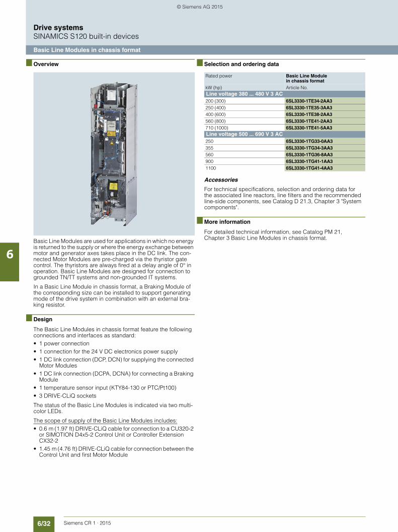
6/32 Siemens CR 1 · 2015
6
Drive systemsSINAMICS S120 built-in devices
Basic Line Modules in chassis format
■ Overview
Basic Line Modules are used for applications in which no energy is returned to the supply or where the energy exchange between motor and generator axes takes place in the DC link. The con-nected Motor Modules are pre-charged via the thyristor gate control. The thyristors are always fired at a delay angle of 0° in operation. Basic Line Modules are designed for connection to grounded TN/TT systems and non-grounded IT systems.
In a Basic Line Module in chassis format, a Braking Module of the corresponding size can be installed to support generating mode of the drive system in combination with an external bra-king resistor.
■ Design
The Basic Line Modules in chassis format feature the following connections and interfaces as standard:• 1 power connection• 1 connection for the 24 V DC electronics power supply• 1 DC link connection (DCP, DCN) for supplying the connected
Motor Modules• 1 DC link connection (DCPA, DCNA) for connecting a Braking
Module• 1 temperature sensor input (KTY84-130 or PTC/Pt100)• 3 DRIVE-CLiQ sockets
The status of the Basic Line Modules is indicated via two multi-color LEDs.
The scope of supply of the Basic Line Modules includes:• 0.6 m (1.97 ft) DRIVE-CLiQ cable for connection to a CU320-2
or SIMOTION D4x5-2 Control Unit or Controller Extension CX32-2
• 1.45 m (4.76 ft) DRIVE-CLiQ cable for connection between the Control Unit and first Motor Module
■ Selection and ordering data
Accessories
For technical specifications, selection and ordering data for the associated line reactors, line filters and the recommended line-side components, see Catalog D 21.3, Chapter 3 "System components".
■ More information
For detailed technical information, see Catalog PM 21, Chapter 3 Basic Line Modules in chassis format.
Rated power Basic Line Module in chassis format
kW (hp) Article No.Line voltage 380 ... 480 V 3 AC200 (300) 6SL3330-1TE34-2AA3250 (400) 6SL3330-1TE35-3AA3400 (600) 6SL3330-1TE38-2AA3560 (800) 6SL3330-1TE41-2AA3710 (1000) 6SL3330-1TE41-5AA3Line voltage 500 ... 690 V 3 AC250 6SL3330-1TG33-0AA3355 6SL3330-1TG34-3AA3560 6SL3330-1TG36-8AA3900 6SL3330-1TG41-1AA31100 6SL3330-1TG41-4AA3
© Siemens AG 2015
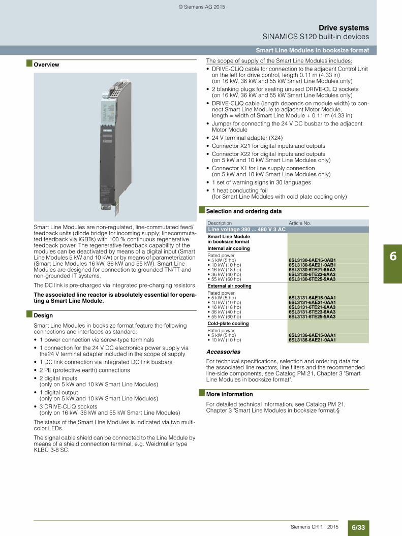
6/33Siemens CR 1 · 2015
6
Drive systemsSINAMICS S120 built-in devices
Smart Line Modules in booksize format
■ Overview
Smart Line Modules are non-regulated, line-commutated feed/feedback units (diode bridge for incoming supply; linecommuta-ted feedback via IGBTs) with 100 % continuous regenerative feedback power. The regenerative feedback capability of the modules can be deactivated by means of a digital input (Smart Line Modules 5 kW and 10 kW) or by means of parameterization (Smart Line Modules 16 kW, 36 kW and 55 kW). Smart Line Modules are designed for connection to grounded TN/TT and non-grounded IT systems.
The DC link is pre-charged via integrated pre-charging resistors.
The associated line reactor is absolutely essential for opera-ting a Smart Line Module.
■ Design
Smart Line Modules in booksize format feature the following connections and interfaces as standard:• 1 power connection via screw-type terminals• 1 connection for the 24 V DC electronics power supply via
the24 V terminal adapter included in the scope of supply• 1 DC link connection via integrated DC link busbars• 2 PE (protective earth) connections• 2 digital inputs
(only on 5 kW and 10 kW Smart Line Modules)• 1 digital output
(only on 5 kW and 10 kW Smart Line Modules)• 3 DRIVE-CLiQ sockets
(only on 16 kW, 36 kW and 55 kW Smart Line Modules)
The status of the Smart Line Modules is indicated via two multi-color LEDs.
The signal cable shield can be connected to the Line Module by means of a shield connection terminal, e.g. Weidmüller type KLBÜ 3-8 SC.
The scope of supply of the Smart Line Modules includes:• DRIVE-CLiQ cable for connection to the adjacent Control Unit
on the left for drive control, length 0.11 m (4.33 in)(on 16 kW, 36 kW and 55 kW Smart Line Modules only)
• 2 blanking plugs for sealing unused DRIVE-CLiQ sockets(on 16 kW, 36 kW and 55 kW Smart Line Modules only)
• DRIVE-CLiQ cable (length depends on module width) to con-nect Smart Line Module to adjacent Motor Module, length = width of Smart Line Module + 0.11 m (4.33 in)
• Jumper for connecting the 24 V DC busbar to the adjacent Motor Module
• 24 V terminal adapter (X24)• Connector X21 for digital inputs and outputs• Connector X22 for digital inputs and outputs
(on 5 kW and 10 kW Smart Line Modules only)• Connector X1 for line supply connection
(on 5 kW and 10 kW Smart Line Modules only)• 1 set of warning signs in 30 languages• 1 heat conducting foil
(for Smart Line Modules with cold plate cooling only)
■ Selection and ordering data
Accessories
For technical specifications, selection and ordering data for the associated line reactors, line filters and the recommended line-side components, see Catalog PM 21, Chapter 3 "Smart Line Modules in booksize format".
■ More information
For detailed technical information, see Catalog PM 21, Chapter 3 "Smart Line Modules in booksize format.§
Description Article No.Line voltage 380 ... 480 V 3 ACSmart Line Modulein booksize formatInternal air cooling
Rated power• 5 kW (5 hp) 6SL3130-6AE15-0AB1• 10 kW (10 hp) 6SL3130-6AE21-0AB1• 16 kW (18 hp) 6SL3130-6TE21-6AA3• 36 kW (40 hp) 6SL3130-6TE23-6AA3• 55 kW (60 hp) 6SL3130-6TE25-5AA3External air cooling
Rated power• 5 kW (5 hp) 6SL3131-6AE15-0AA1• 10 kW (10 hp) 6SL3131-6AE21-0AA1• 16 kW (18 hp) 6SL3131-6TE21-6AA3• 36 kW (40 hp) 6SL3131-6TE23-6AA3• 55 kW (60 hp) 6SL3131-6TE25-5AA3Cold-plate cooling
Rated power• 5 kW (5 hp) 6SL3136-6AE15-0AA1• 10 kW (10 hp) 6SL3136-6AE21-0AA1
© Siemens AG 2015

6/34 Siemens CR 1 · 2015
6
Drive systemsSINAMICS S120 built-in devices
Smart Line Modules in chassis format
■ Overview
Smart Line Modules are non-regulated feed/feedback units with 100 % continuous regenerative feedback power. The regenera-tive feedback capability of the modules can be deactivated by-means of parameterization.Smart Line Modules are designed for connection to grounded TN/TT and non-grounded IT systems.
The DC link is pre-charged via integrated pre-charging resistors.
The associated line reactor is absolutely essential for opera-ting a Smart Line Module.
■ Design
The Smart Line Modules have the following interfaces as standard:• 1 power connection• 1 connection for the 24 V DC electronics power supply• 1 DC link connection (DCPA, DCNA) for connecting a Braking
Module• 3 DRIVE-CLiQ sockets• 1 PE (protective earth) connection (2 connections for frame
sizes HX and JX)
The status of the Smart Line Modules is indicated via two multi-color LEDs.
The scope of supply of the Smart Line Modules includes:• DRIVE-CLiQ cable to connect to a CU320-2 or
SIMOTION D4x5-2 Control Unit or Controller Extension CX32-2
• DRIVE-CLiQ cable for connection between the Control Unit and first Motor Module (type dependent)
■ Selection and ordering data
Accessories
For accessories, technical specifications, and selection and or-dering data for the associated line reactors, line filters and the recommended line-side components, see Catalog D 21.3, Chapter 2 "System components".
■ More information
For detailed technical information, see Catalog PM 21, Chapter 3 "Smart Line Modules in chassis format".
Rated power Smart Line Module in chassis format
kW (hp) Article No.Line voltage 380 ... 480 V 3 AC250 (400) 6SL3330-6TE35-5AA3355 (500) 6SL3330-6TE37-3AA3500 (700) 6SL3330-6TE41-1AA3630 (800) 6SL3330-6TE41-3AA3800 (1000) 6SL3330-6TE41-7AA3Line voltage 500 ... 690 V 3 AC450 6SL3330-6TG35-5AA3710 6SL3330-6TG38-8AA31000 6SL3330-6TG41-2AA31400 6SL3330-6TG41-7AA3
© Siemens AG 2015

6/35Siemens CR 1 · 2015
6
Drive systemsSINAMICS S120 built-in devices
Active Line Modules in booksize format
■ Overview
Active Line Modules are self-commutated feed/feedback units (with IGBTs in infeed and regenerative feedback directions) and generate a regulated DC link voltage. This means that the con-nected Motor Modules are decoupled from the line voltage. Line voltage fluctuations within the permissible supply tolerances have no effect on the motor voltage. Active Line Modules are designed for connection to grounded, star (TN, TT) and non-grounded, symmetrical IT systems.
The DC link is pre-charged via integrated pre-charging resistors.
In order to operate an Active Line Module, it is absolutely essential to use the appropriate Active Interface Module.
■ Design
The Active Line Modules in booksize format feature the following connections and interfaces as standard:• 1 power connection via screw-type terminals• 1 connection for the 24 V DC electronics power supply via the
24 V terminal adapter included in the scope of supply• 1 DC link connection via integrated DC link busbars• 3 DRIVE-CLiQ sockets• 2 PE (protective earth) connections
The status of the Active Line Modules is indicated via two multi-color LEDs.
On the 100 mm (3.94 in) wide Active Line Module, the shield for the power supply cable can be connected to the integrated shield connection plate via a shield connection terminal or tube clip, e.g. Weidmüller type KLBÜ CO 4. The shield connection terminal must not be used for strain relief. Shield connection pla-tes are available for the 150 mm (5.91 in), 200 mm (7.87 in) and 300 mm (11.81 in) wide modules.
The signal cable shield can be connected to the Line Module by means of a shield connection terminal, e.g. Weidmüller type KLBÜ 3-8 SC.
The scope of supply of the Active Line Modules includes:• DRIVE-CLiQ cable for connection to the adjacent Control Unit
on the left for drive control, length 0.11 m (4.33 in)• DRIVE-CLiQ cable (length depends on module width) to
connect Active Line Module to adjacent Motor Module, length = width of Active Line Module + 0.11 m (4.33 in)
• 2 blanking plugs for sealing unused DRIVE-CLiQ sockets• Jumper for connecting the 24 V DC busbar to the adjacent
Motor Module• 24 V terminal adapter (X24)• Connector X21 for digital inputs• Fan insert for Active Line Modules of 80 kW (107 hp) and
120 kW (161 hp) (the voltage is supplied by the Active Line Module)
• 1 set of warning signs in 30 languages• 1 heat conducting foil
(for Active Line Modules with cold plate cooling only)
■ Selection and ordering data
Accessories
For technical specifications, selection and ordering data for the line reactors, Wideband Line Filters, Basic Line Filters and the recommended line-side components, see Catalog PM 21, Chap-ter 3 "Active Line Modules in booksize format".
■ More information
For detailed technical information, see Catalog PM 21, Chapter 3 "Active Line Modules in booksize format".
Active Line Module in booksize format
Description Article No.Line voltage 380 ... 480 V 3 ACInternal air cooling
Rated power• 16 kW (18 hp) 6SL3130-7TE21-6AA3• 36 kW (40 hp) 6SL3130-7TE23-6AA3• 55 kW (60 hp) 6SL3130-7TE25-5AA3• 80 kW (100 hp) 6SL3130-7TE28-0AA3• 120 kW (150 hp) 6SL3130-7TE31-2AA3External air cooling
Rated power• 16 kW (18 hp) 6SL3131-7TE21-6AA3• 36 kW (40 hp) 6SL3131-7TE23-6AA3• 55 kW (60 hp) 6SL3131-7TE25-5AA3• 80 kW (100 hp) 6SL3131-7TE28-0AA3• 120 kW (150 hp) 6SL3131-7TE31-2AA3Cold-plate cooling
Rated power• 16 kW (18 hp) 6SL3136-7TE21-6AA3• 36 kW (40 hp) 6SL3136-7TE23-6AA3• 55 kW (60 hp) 6SL3136-7TE25-5AA3• 80 kW (100 hp) 6SL3136-7TE28-0AA3• 120 kW (150 hp) 6SL3136-7TE31-2AA3Liquid cooling
Rated power• 120 kW (150 hp) 6SL3135-7TE31-2AA3
© Siemens AG 2015

6/36 Siemens CR 1 · 2015
6
Drive systemsSINAMICS S120 built-in devices
Active Interface Modules in booksize format
■ Overview
Active Interface Modules for 16 kW, 36 kW, 55 kW and 80 kW/120 kW
The Active Interface Modules combine with the Active Line Modules to form a functional unit and are essential for operation of the associated Active Line Module. The Active Interface Modules contain a Clean Power Filter, reactor, and basic inter-ference suppression to ensure compliance with Category C3 in accordance with EN 61800-3 regarding emitted interference.
The Clean Power Filter protects the line supply from switching-frequency harmonics. The drive system therefore draws a sinu-soidal current from the supply and causes virtually no harmo-nics.
The Active Line Modules in combination with the Active Interface Module can also be operated with supply systems with an isola-ted star point (IT systems).
■ Design
The scope of supply of the Active Interface Modules includes:• Connector X21 for temperature evaluation and fan control• Connector X24 for connecting the 24 V supply for the integra-
ted fan• DRIVE-CLiQ cable for connecting the Control Unit to the Ac-
tive Line Module; length of the DRIVE-CLiQ cable = width of the Active Interface Module + 0.11 m (4.33 in)
• Shield connection plate for Active Interface Module 16 kW• 1 set of warning signs in 30 languages
■ Selection and ordering data
Accessories
For technical specifications, selection and ordering data for the line reactors, Wideband Line Filters, Basic Line Filters and the recommended line-side components, see Catalog PM 21, Chapter 3 "Active Line Modules in booksize format".
■ More information
For detailed technical information, see Catalog PM 21, Chapter 3 "Active Line Modules in booksize format".
Rated power of the Active Line Module
Suitable for Active Line Module in booksize format
Active Interface Module in booksize format
kW (hp) Article No.Line voltage 380 ... 480 V 3 AC16 (18) 6SL3130-7TE21-6AA3
6SL3131-7TE21-6AA36SL3136-7TE21-6AA3
6SL3100-0BE21-6AB0
36 (40) 6SL3130-7TE23-6AA36SL3131-7TE23-6AA36SL3136-7TE23-6AA3
6SL3100-0BE23-6AB0
55 (60) 6SL3130-7TE25-5AA36SL3131-7TE25-5AA36SL3136-7TE25-5AA3
6SL3100-0BE25-5AB0
80 (100) 6SL3130-7TE28-0AA36SL3131-7TE28-0AA36SL3136-7TE28-0AA3
6SL3100-0BE28-0AB0
120 (150) 6SL3130-7TE31-2AA36SL3131-7TE31-2AA36SL3135-7TE31-2AA36SL3136-7TE31-2AA3
6SL3100-0BE31-2AB0
© Siemens AG 2015

6/37Siemens CR 1 · 2015
6
Drive systemsSINAMICS S120 built-in devices
Active Line Modules in chassis format
■ Overview
The self-commutated feed/feedback units (with IGBTs in infeed and regenerative feedback directions) generate a regulated DC link voltage. This means that the connected Motor Modules are decoupled from the line voltage. Line voltage fluctuations within the permissible supply tolerances have no effect on the motor voltage.
Active Line Modules can if necessary feed a prespecified funda-mental reactive current (capacitive or inductive) to the supply system so as to support simple compensation tasks.
Active Line Modules are designed for connection to grounded TN/TT and non-grounded IT systems.
In order to operate an Active Line Module, it is absolutely essential to use the appropriate Active Interface Module.
■ Design
The Active Line Modules in chassis format feature the following connections and interfaces as standard:• 1 power connection• 1 connection for the 24 V DC electronics power supply• 1 DC link connection (DCP, DCN) for supplying the connected
Motor Modules• 1 DC link connection (DCPA, DCNA) for connecting a Braking
Module• 1 temperature sensor input (KTY84-130 or PTC/Pt100)• 3 DRIVE-CLiQ sockets• 2 PE (protective earth) connections
The status of the Active Line Modules is indicated via two multi-color LEDs.
The scope of supply of the Active Line Modules includes:• Frame sizes FX and GX:
- 0.60 m (23.6 in) DRIVE-CLiQ cable for connection to the CU320-2 or SIMOTION D4x5-2 Control Unit or Controller Extension CX32-2
• Frame sizes HX and JX- 0.35 m (13.8 in) DRIVE-CLiQ cable for connection to the
CU320-2 or SIMOTION D4x5-2 Control Unit or Controller Extension CX32-2
- 2.10 m (6.89 ft) DRIVE-CLiQ cable for connection to the first Motor Module
■ Selection and ordering data
Accessories
For technical specifications, selection and ordering data for the line reactors, Wideband Line Filters, Basic Line Filters and the recommended line-side components, see Catalog PM 21, Chapter 3 "Active Line Modules in booksize format".
■ More information
For detailed technical information, see Catalog PM 21, Chapter 3 "Active Line Modules in chassis format".
Rated power Active Line Module in chassis format
kW (hp) Article No.Line voltage 380 ... 480 V 3 AC132 (200) 6SL3330-7TE32-1AA3160 (225) 6SL3330-7TE32-6AA3235 (350) 6SL3330-7TE33-8AA3300 (450) 6SL3330-7TE35-0AA3380 (550) 6SL3330-7TE36-1AA3500 (700) 6SL3330-7TE37-5AA3630 (800) 6SL3330-7TE38-4AA3900 (1150) 6SL3330-7TE41-0AA3Line voltage 500 ... 690 V 3 AC560 6SL3330-7TG35-8AA3800 6SL3330-7TG37-4AA31100 6SL3330-7TG41-0AA31400 6SL3330-7TG41-3AA3
© Siemens AG 2015

6/38 Siemens CR 1 · 2015
6
Drive systemsSINAMICS S120 built-in devices
Active Interface Modules in chassis format
■ Overview
Active Interface Modules are used in combination with Active Line Modules in chassis format. Active Interface Modules con-tain a Clean Power Filter with basic RI suppression, reactor, the pre-charging circuit for the Active Line Module, the line voltage sensing circuit and monitoring sensors. The bypass connector is an integral component in types FI and GI, thereby making the module very compact. The bypass contactor must be provided separately for frame sizes HI and JI.
The vast majority of line harmonics are suppressed by the Clean Power Filter.
The scope of supply of the Active Interface Modules includes:• DRIVE-CLiQ cable for connection between Active Interface
Module and Active Line Module• DRIVE-CLiQ cable for connection between the Control Unit
and first Motor Module
■ Selection and ordering data
Accessories
For accessories, see Catalog D 21.3, Chapter 2 "System Components".
■ More information
For detailed technical information, see Catalog PM 21 Chapter 3 "Active Line Modules in chassis format".
Rated power of the Active Line Module
Suitable for Active Line Module in chassis format
Active Interface Module
kW (hp) Article No.Line voltage 380 ... 480 V 3 AC132 (200) 6SL3330-7TE32-1AA3 6SL3300-7TE32-6AA0160 (225) 6SL3330-7TE32-6AA3 6SL3300-7TE32-6AA0235 (350) 6SL3330-7TE33-8AA3 6SL3300-7TE33-8AA0300 (450) 6SL3330-7TE35-0AA3 6SL3300-7TE35-0AA0380 (550) 6SL3330-7TE36-1AA3 6SL3300-7TE38-4AA0450 (600) 6SL3330-7TE37-5AA3 6SL3300-7TE38-4AA0500 (700) 6SL3330-7TE38-4AA3 6SL3300-7TE38-4AA0630 (800) 6SL3330-7TE41-0AA3 6SL3300-7TE41-4AA0800 (1000) 6SL3330-7TE41-2AA3 6SL3300-7TE41-4AA0900 (1150) 6SL3330-7TE41-4AA3 6SL3300-7TE41-4AA0Line voltage 500 ... 690 V 3 AC560 6SL3330-7TG35-8AA3 6SL3300-7TG35-8AA0800 6SL3330-7TG37-4AA3 6SL3300-7TG37-4AA01100 6SL3330-7TG41-0AA3 6SL3300-7TG41-3AA01400 6SL3330-7TG41-3AA3 6SL3300-7TG41-3AA0
© Siemens AG 2015

6/39Siemens CR 1 · 2015
6
Drive systemsSINAMICS S120 built-in devices
Single Motor Modules in booksize format
■ Design
Single Motor Module in booksize format
In principle, all Single Motor Modules can be operated on Basic Line Modules, Smart Line Modules, or Active Line Modules of the appropriate voltage range.A broad range of Single Motor Modules is available graded ac-cording to current and power.
The Single Motor Modules in booksize format feature the fol-lowing connections and interfaces as standard:• 2 DC link connections via integrated DC link busbars• 1 electronics power supply connection via integrated 24 V DC
busbars• 3 DRIVE-CLiQ sockets• 1 motor connection, plug-in (not included in scope of supply)
or screw-stud depending on rated output current• 1 safe standstill input (enable pulses)• 1 safe motor brake control• 1 temperature sensor input (KTY84-130 or PTC)• 2 PE (protective earth) connections
The status of the Motor Modules is indicated via two multi-color LEDs.
The motor cable shield is inside the connector on 50 mm (1.97 in) and 100 mm (3.94 in) wide Motor Modules. A shield connection plate can be supplied for 150 mm (5.91 in), 200 mm (7.87 in) and 300 mm (11.8 in) wide Motor Modules. On these modules, the motor cable shield can be connected using a tube clip.
The signal cable shield can be connected to the Motor Module by means of a shield connection terminal, e.g. Weidmüller type KLBÜ 3-8 SC.
The scope of supply of the Motor Modules includes:• DRIVE-CLiQ cable appropriate to the width of the Motor
Module for connection to the adjacent Motor Module, length = width of Motor Module + 0.06 m (2.4 in)
• Jumper for connecting the 24 V DC busbar to the adjacent Motor Module
• Connector X21• Connector X11 for the motor brake connection
(for Motor Modules with a rated output current of 45 A to 200 A)
• 2 blanking plugs for sealing unused DRIVE-CLiQ sockets• Fan insert for the 132 A and 200 A Motor Modules
(the voltage for the fan insert is supplied by the Motor Module)• 1 set of warning signs in 30 languages• 1 heat conducting foil
(for Motor Modules with cold plate cooling only)
© Siemens AG 2015

6/40 Siemens CR 1 · 2015
6
Drive systemsSINAMICS S120 built-in devices
Single Motor Modules in booksize format
■ Selection and ordering data
Accessories
For selection and ordering data regarding the load-side power components and the DC link components, see Catalog PM 21, Chapter 3 "Load-side power components" and "DC link compo-nents".
■ More information
For detailed technical information, see Catalog PM 21, Chapter 3 "Single Motor Modules in booksize format".
Rated output current Type rating Single Motor Module in booksize formatInternal air cooling External air cooling Cold-plate cooling Liquid cooling
A kW (hp) 1) Article No. Article No. Article No. Article No.DC link voltage 510 ... 720 V DC3 1.6 (1.5) 6SL3120-1TE13-0AA4 6SL3121-1TE13-0AA4 6SL3126-1TE13-0AA4 –5 2.7 (3) 6SL3120-1TE15-0AA4 6SL3121-1TE15-0AA4 6SL3126-1TE15-0AA4 –9 4.8 (5) 6SL3120-1TE21-0AA4 6SL3121-1TE21-0AA4 6SL3126-1TE21-0AA4 –18 9.7 (10) 6SL3120-1TE21-8AA4 6SL3121-1TE21-8AA4 6SL3126-1TE21-8AA4 –30 16 (20) 6SL3120-1TE23-0AA3 6SL3121-1TE23-0AA3 6SL3126-1TE23-0AA3 –45 24 (30) 6SL3120-1TE24-5AA3 6SL3121-1TE24-5AA3 6SL3126-1TE24-5AA3 –60 32 (40) 6SL3120-1TE26-0AA3 6SL3121-1TE26-0AA3 6SL3126-1TE26-0AA3 –85 46 (60) 6SL3120-1TE28-5AA3 6SL3121-1TE28-5AA3 6SL3126-1TE28-5AA3 –132 71 (100) 6SL3120-1TE31-3AA3 6SL3121-1TE31-3AA3 6SL3126-1TE31-3AA3 –200 107 (150) 6SL3120-1TE32-0AA4 6SL3121-1TE32-0AA4 6SL3126-1TE32-0AA4 6SL3125-1TE32-0AA4
© Siemens AG 2015

6/41Siemens CR 1 · 2015
6
Drive systemsSINAMICS S120 built-in devices
Single Motor Modules in chassis format
■ Design
A Motor Module comprises a self-commutated inverter with IGBTs. It generates a variable voltage with variable frequency from the DC link voltage that feeds the connected motor. Several Motor Modules can be interconnected through a common DC bus. This permits energy to be transferred between the Motor Modules.This means that if one Motor Module operating in generator mode produces energy, the energy can be used by another Mo-tor Module operating in motor mode. Motor Modules are controlled by a Control Unit.
Single Motor Modules in chassis format
The Single Motor Modules in chassis format feature the following connections and interfaces as standard:• 1 DC link connection (DCP, DCN) for connecting to the supply
DC busbar• 1 DC link connection (DCPA, DCNA) for connecting a Braking
Module• 1 electronics power supply connection• 3 DRIVE-CLiQ sockets• 1 motor connection• 1 safe standstill input (enable pulses)• 1 temperature sensor input (KTY84-130 or Pt100 two-wire, or
PTC)• 1 connection for Safe Brake Adapter• 1 PE (protective earth) connection
The status of the Motor Modules is indicated via two multi-color LEDs.
The scope of supply of the Motor Modules includes:• DRIVE-CLiQ cable for connection to the adjacent Motor Mo-
dule (depends on type)• DRIVE-CLiQ cable for connection to the CU320 Control Unit or
SIMOTION D4x5 Control Unit
■ Selection and ordering data
Accessories
For selection and ordering data for the load-side power components and the DC link components, see Catalog D 21.3, Chapter 2 "System Components".
■ More information
For detailed technical information, see Catalog PM 21 Chapter 3 "Single Motor Modules in chassis format".
Rated output current Type rating Single Motor Module in chassis format
A kW (hp) 1) Article No.DC link voltage 510 ... 720 V DC210 110 (150) 6SL3320-1TE32-1AA3260 132 (200) 6SL3320-1TE32-6AA3310 160 (250) 6SL3320-1TE33-1AA3380 200 (300) 6SL3320-1TE33-8AA3490 250 (400) 6SL3320-1TE35-0AA3605 315 (500) 6SL3320-1TE36-1AA3745 400 (600) 6SL3320-1TE37-5AA3840 450 (700) 6SL3320-1TE38-4AA3985 560 (800) 6SL3320-1TE41-0AA31260 710 (1000) 6SL3320-1TE41-2AA31405 800 (1150) 6SL3320-1TE41-4AA3DC link voltage 675 ... 1035 V DC85 75 6SL3320-1TG28-5AA3100 90 6SL3320-1TG31-0AA3120 110 6SL3320-1TG31-2AA3150 132 6SL3320-1TG31-5AA3175 160 6SL3320-1TG31-8AA3215 200 6SL3320-1TG32-2AA3260 250 6SL3320-1TG32-6AA3330 315 6SL3320-1TG33-3AA3410 400 6SL3320-1TG34-1AA3465 450 6SL3320-1TG34-7AA3575 560 6SL3320-1TG35-8AA3735 710 6SL3320-1TG37-4AA3810 800 6SL3320-1TG38-1AA3910 900 6SL3320-1TG38-8AA31025 1000 6SL3320-1TG41-0AA31270 1200 6SL3320-1TG41-3AA3
1) Nominal hp ratings based on asynchronous (induction) motors. Match the motor nameplate current for specific sizing.
© Siemens AG 2015

6/42 Siemens CR 1 · 2015
6
Drive systemsSINAMICS S120 Cabinet Modules
■ Overview
In the SINAMICS S120 Cabinet Modules, the built-in units of the SINAMICS S120 chassis format are integrated to provide a modular cabinet system for multi-motor drives with a central line infeed and a common DC link busbar for crane systems. As standard, they are installed side by side in a row.
The main components of the system in crane applications are as follows:• Line Connection Modules with line-side components such as
contactors, fuses and circuit breakers• Line Modules for infeed in the Active Line Module version for
four-quadrant mode with negligible line harmonic distortion and integrated line contactors
• Motor Modules in chassis format for controlling motors• Switch-Over Modules for both economic and redundant
combinations of motors and Motor Modules• Motor Multi Connection Modules for parallel connection of
motors for gantry drives in particular• Motor Double Choke Modules for connecting a reactor bet-
ween Motor Modules and motors when long cables are used, as is the case in gantry drives
The industry-specific version Cranes ordering option B70 is based on the requirements of the EN 60204-32 standard and implements the measures required for the cabinet units.
Specification in contrast to the available standard cabinet design:• All auxiliary power supplies are routed to terminals for wiring
in star topology• Vibrational load in operation
- Deflection 1.0 mm at 2 to 13.2 Hz - Acceleration 6.8 m/s² at 13.2 to 100 Hz
• The colors of the cores are in accordance with DIN EN 60204-32 except in the case of built-in Chassis Modules
• The complete documentation is supplied for the cabinets for the ordered configuration
• Internal wiring of the transport units• Prepared wiring for easy assembly
Component overview based on the example of a container crane with Cabinet Modules
When used in cranes, the industry-specific option B70 must be specified separately on ordering for all cabinets.
~~=
~= =
~=
~= 12x
GantryHoisting gearTrolley Jib
G_CR01_EN_00324
Switch-Over
Module
Switch-Over
Module
Switch-Over
Module
MotorDoubleChokeModule
MotorMulti
ConnectionModule
PROFIBUS-DP
DRIVE-QLiQ
MotorModule
MotorModule
MotorModule
Active InfeedModule
Active InfeedModule
Line ConnectionModule
© Siemens AG 2015

6/43Siemens CR 1 · 2015
6
Drive systemsSINAMICS S120 Cabinet Modules
■ Characteristic curves
Derating data for the chassis format
SINAMICS G120 Cabinet Modules and the associated system components are rated for an ambient temperature of 40 °C and installation altitudes up to 2000 m above sea level.
At ambient temperatures of > 40 °C, the output current must be reduced. Ambient temperatures above 50 °C are not permissi-ble.
At installation altitudes > 2000 m above sea level, it must be ta-ken into account that the air pressure, and therefore air density, decreases as the height increases. As a consequence, the coo-ling efficiency and the insulation capacity of the air also decre-ase.
Due to the reduced cooling efficiency, it is necessary, on the one hand, to reduce the ambient temperature and, on the other, to lo-wer heat loss in the Cabinet Module by reducing the output cur-rent, whereby ambient temperatures lower than 40 °C may be offset to compensate.
The following table specifies the permissible output currents as a function of the installation altitude and ambient temperature for the various degrees of protection (the permissible compensation between installation altitude and the ambient temperatures < 40 °C – air intake temperature at the entry to the Cabinet Module – has been taken into account in the specified values).
The values apply under the precondition that it is ensured that the cooling air, as specified in the technical specifications, flows through the units as a result of the cabinet arrangement.
As additional measure for installation altitudes from 2000 to 5000 m, an isolating transformer is required in order to reduce transient overvoltages according to EN 60664-1. For additional information about this, please refer to the SINAMICS Low Voltage Engineering Manual.
Current derating factors for Cabinet Modules as a function of the ambient/air intake temperature, the installation altitude and the degree of protection
Current derating for SINAMICS S120 Motors Modules,chassis format as a function of the pulse frequency
To reduce motor noise or to increase output frequency, the pulse frequency can be increased relative to the factory setting. When the pulse frequency is increased, the derating factor of the out-put current must be taken into account. This derating factor must
be applied to the currents specified in the technical specifica-tions.For additional information about this, please refer to the SINAMICS Low Voltage Engineering Manual.
Derating factor of the output current as a function of the pulse frequency for devices with a rated pulse frequency of 2 kHz
Derating factor of the output current as a function of the pulse frequency for devices with a rated pulse frequency of 1.25 kHz
Degree of protection
Installation altitude above sea level
Current derating factor (as a % of the rated current)for an ambient/air intake temperature of
m 20 °C 25 °C 30 °C 35 °C 40 °C 45 °C 50 °C
IP20, IP21, IP23 0 ... 2000 100 % 100 % 100 % 100 % 100 % 93.3 % 86.7 %
2001 ... 2500 100 % 100 % 100 % 100 % 96.3 %
2501 ... 3000 100 % 100 % 100 % 98.7 %
3001 ... 3500 100 % 100 % 100 %
3501 ... 4000 100 % 100 % 96.3 %
4001 ... 4500 100 % 97.5 %
4501 ... 5000 98.2 %
Motor Module in chassis format
Type rating at 400 V
Output currentat 2 kHz
Derating factorat pulse frequency
6SL3720-... kW A 2.5 kHz 4 kHz 5 kHz 7.5 kHz 8 kHz
380 … 480 V 3 AC
1TE32-1AA3 110 210 95 % 82 % 74 % 54 % 50 %
1TE32-6AA3 132 260 95 % 83 % 74 % 54 % 50 %
1TE33-1AA3 160 310 97 % 88 % 78 % 54 % 50 %
1TE33-8AA3 200 380 96 % 87 % 77 % 54 % 50 %
1TE35-0AA3 250 490 94 % 78 % 71 % 53 % 50 %
Motor Module in chassis format
Type rating at 400 V or 690 V
Output currentat 1.25 kHz
Derating factorat pulse frequency
6SL3720-... kW A 2.0 kHz 2.5 kHz 4 kHz 5 kHz 7.5 kHz
380 … 480 V 3 AC
1TE36-1AA3 315 605 83 % 72 % 64 % 60 % 40 %
1TE37-5AA3 400 745 83 % 72 % 64 % 60 % 40 %
1TE38-4AA3 450 840 87 % 79 % 64 % 55 % 40 %
1TE41-0AA3 560 985 92 % 87 % 70 % 60 % 50 %
1TE41-2AA3 710 1260 92 % 87 % 70 % 60 % 50 %
1TE41-4AA3 800 1405 97 % 95 % 74 % 60 % 50 %
© Siemens AG 2015

6/44 Siemens CR 1 · 2015
6
■ Characteristic curves (continued)
Drive systemsSINAMICS S120 Cabinet Modules
The following table lists the maximum achievable output fre-quency as a function of the pulse frequency:
Overload capability
SINAMICS S120 Cabinet Modules have an overload reserve, e.g. to handle breakaway torques. If larger surge loads occur, this must be taken into account when configuring. In drives with overload requirements, the appropriate base-load current must, therefore, be used as a basis for the required load.
Permissible overload assumes that the drive converter is opera-ted at its base-load current before and after the overload occurs, based on a duty cycle duration of 300 s.
For temporary, periodic duty cycles with high variations of load within the duty cycle, the relevant sections of the SINAMICS Low Voltage Engineering Manual must be observed.
Motor Modules in chassis format
Motor Modules with power units in chassis format can be confi-gured on the basis of different base-load currents.
The base-load current for a low overload IL is based on a duty cycle of 110 % for 60 s or 150 % for 10 s.
The base-load current for a high overload IH is based on a duty cycle of 150 % for 60 s or 160 % for 10 s.
Line Modules in chassis format
The base-load current for a high overload IH DC is based on a duty cycle of 150 % for 60 s or Imax DC for 5 s.Pulse frequency Max. achievable output frequency
1.25 kHz 100 Hz
2.00 kHz 160 Hz
2.50 kHz 200 Hz
≥ 4.00 kHz 300 Hz
60 s
10 s
300 s
t
1.1 x IL
1.5 x IL
Short-time current 110 %
Short-time current 150 %
Rated current (continuous)
Converter current
G_D
213_
EN
_000
35
Base-load current IL for low overload
ILIrated
60 s
10 s
t
1.5 x IH
1.6 x IH Short-time current 160 %
Short-time current 150 %
Rated current (continuous)
Converter current
G_D
213_
EN
_000
36
Base-load current IH for high overload
IH
Irated
300 s
60 s
5 s
t
300 s
Irated DC
IH DC
Base-load current IH DC for high overload
G_D
213_
EN
_000
79
Converter current
Rated current (continuous)
Short-time current 150 %
Short-time current Imax Imax DC
1.5 x IH DC
© Siemens AG 2015
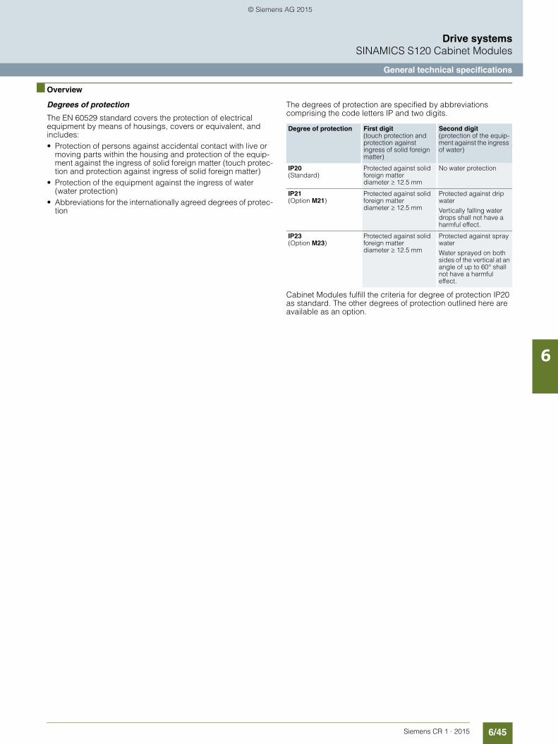
6/45Siemens CR 1 · 2015
6
Drive systemsSINAMICS S120 Cabinet Modules
General technical specifications
■ Overview
Degrees of protection
The EN 60529 standard covers the protection of electrical equipment by means of housings, covers or equivalent, and includes:• Protection of persons against accidental contact with live or
moving parts within the housing and protection of the equip-ment against the ingress of solid foreign matter (touch protec-tion and protection against ingress of solid foreign matter)
• Protection of the equipment against the ingress of water (water protection)
• Abbreviations for the internationally agreed degrees of protec-tion
The degrees of protection are specified by abbreviations comprising the code letters IP and two digits.
Cabinet Modules fulfill the criteria for degree of protection IP20 as standard. The other degrees of protection outlined here are available as an option.
Degree of protection First digit(touch protection and protection against ingress of solid foreign matter)
Second digit(protection of the equip-ment against the ingress of water)
IP20(Standard)
Protected against solid foreign matterdiameter ≥ 12.5 mm
No water protection
IP21(Option M21)
Protected against solid foreign matterdiameter ≥ 12.5 mm
Protected against drip water
Vertically falling water drops shall not have a harmful effect.
IP23(Option M23)
Protected against solid foreign matterdiameter ≥ 12.5 mm
Protected against spray water
Water sprayed on both sides of the vertical at an angle of up to 60° shall not have a harmful effect.
© Siemens AG 2015

6/46 Siemens CR 1 · 2015
6
Drive systemsSINAMICS S120 Cabinet Modules
General technical specifications
■ Technical specifications
Unless specified otherwise, the following technical specifica-tions are valid for all the following components of the SINAMICS S120 Cabinet Modules.
Electrical dataLine voltages 380 … 480 V 3 AC, ±10 % (-15 % < 1 min)Line supply types Isolated systems (IT systems)Line frequency 47 ... 63 HzOutput frequency 0 … 300 Hz (> 100/160 Hz, observe the derating)Line power factorFundamental
Active Line Module
Adjustable (factory-set to cosϕ = 1)Efficiency > 97.0 %Control method Vector/servo control with and without encoder or V/f controlFixed speeds 15 fixed speeds plus 1 minimum speed, parameterizable (in the default setting, 3 fixed setpoints plus 1 minimum
speed are selectable using terminal block/PROFIBUS/PROFINET)Skipped speed ranges 4, programmableBraking operation With regenerative feedback, or the use of an optional brake chopper and braking resistorsMechanical data
Degree of protection IP20 (higher degrees of protection up to IP23 optional)Protection class I acc. to EN 61800-5-1Touch protection EN 50274/BGV A3 for the intended purposeCabinet system Rittal TS 8, doors with double-barb lock, three-section base plates for cable entryPaint finish RAL 7035 (indoor requirements)Cooling method Forced air cooling AF to EN 60146-1-1Ambient conditions Storage 1) Transport 1) Operation
Ambient temperature -25 ... +55 °C -25 ... +70 °Cabove -40 °C2) for 24 hours
0 ... +40 °Cto +50 °C see derating data
Relative humidity(condensation not permissible)
5 ... 95 % 2)
Class 1K4 acc. to IEC 60721-3-15 ... 95 % at 40 °CClass 2K3 acc. to IEC 60721-3-2
5 ... 95 % 2)
Class 3K3 acc. to IEC 60721-3-3Environmental class/harmful chemical substances
Class 1C2acc. to EN 60721-3-1
Class 2C2acc. to EN 60721-3-2
Class 3C2acc. to EN 60721-3-3
Organic/biological influences Class 1B1acc. to EN 60721-3-1
Class 2B1acc. to EN 60721-3-2
Class 3B1acc. to EN 60721-3-3
Degree of pollution 2 acc. to EN 61800-5-1 2 acc. to EN 61800-5-1 2 acc. to EN 61800-5-1Installation altitude Cabinet Modules, chassis format:
up to 2000 m above sea level, without derating, > 2000 m, see characteristic curves/derating data Mechanical stability Storage 1) Transport 1) Operation
Vibratory load Class 1M1acc. to EN 60721-3-1
Class 2M1acc. to EN 60721-3-2
–
• Deflection 1.5 mm at 5 ... 9 Hz 3.1 mm at 5 ... 9 Hz 0.075 mm at 10 ... 58 Hz- With option B70 – – 1.0 mm at 2 ... 13.2 Hz
• Acceleration 5 m/s² at > 9 ... 200 Hz 10 m/s² at > 9 ... 200 Hz 9.8 m/s² at > 58 ... 200 Hz- With option B70 – – 6.8 m/s² at > 13.2 ... 100 Hz
Shock load Class 1M1acc. to EN 60721-3-1
Class 2M1acc. to EN 60721-3-2
Class 3M1acc. to EN 60721-3-3
• Acceleration 40 m/s² at 22 ms 100 m/s² at 11 ms 100 m/s² at 11 msCompliance with standards
Conformances/approvals, according to CE (EMC directive No. 2004/108/EC and low-voltage directive No. 2006/95/EC) and Machinery Directive No. 2006/42/EC for functional safety)
Radio interference suppression SINAMICS drive converter systems are not designed for connection to the public grid (first environment). Radio interference suppression is compliant with the EMC product standard for variable-speed drives EN 61800-3, "Second environment" (industrial line supplies). The equipment can cause electromagnetic interference when it is connected to the public network. However, if supplementary measures are taken (e.g. → line filter), it can also be operated in the "first environment".
1) In transport packaging.2) Deviations with respect to the specified class are underlined.
© Siemens AG 2015

6/47Siemens CR 1 · 2015
6
■ Technical specifications (continued)
Drive systemsSINAMICS S120 Cabinet Modules
General technical specifications
Listed below are the most important directives and standards that apply to the SINAMICS S120 Cabinet Modules drive system. They must be carefully observed to achieve a system design that is functionally reliable, operationally safe and compliant with EMC guidelines
European directives
2006/95/EC Low-voltage directive: Legal guidelines of the EU member states concerning electrical equipment for use within specified voltage limits
2004/108/EC EMC directive: Legal guidelines of the EU member states for electromagnetic compatibility
2006/42/EC Machinery directive:Legal guidelines of the EU member states for machines
European standards
EN ISO 3744 Acoustics – Determination of sound power levels and sound energy levels of noise sources using sound pressure –Survey method using an enveloping measurement surface, accuracy class 2, for an essentially free acoustic field over areflecting plane.
EN ISO 13849-1 Safety of machinery – safety-related parts of control systems Part 1: General design principles (ISO 13849-1: 2006)
EN 60146-1-1 Semiconductor converters – General requirements and line-commutated converters Part 1-1: Specification of basic requirements
EN 60204-1 Safety of machinery – Electrical equipment of machinesPart 1: General requirements
EN 60529 Degrees of protection provided by enclosures (IP code)
EN 61508-1 Functional safety of electrical/electronic/programmable electronic safety-related systemsPart 1: General requirements
EN 61800-2 Variable-speed electric drivesPart 2: General requirements – Rating specifications for low voltage adjustable frequency AC power drive systems
EN 61800-3 Variable-speed electric drivesPart 3: EMC requirements including specific test methods
EN 61800-5-1 Adjustable speed electrical power drive systemsPart 5: Safety requirementsMain section 1: Electrical and thermal requirements
EN 61800-5-2 Adjustable-speed electrical power drive systemsPart 5-2: Safety requirements – Functional safety (IEC 61800-5-2: 2007)
© Siemens AG 2015
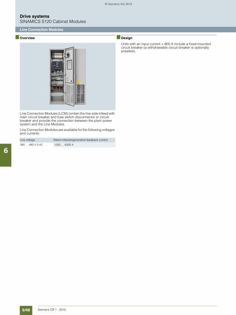
6/48 Siemens CR 1 · 2015
6
Drive systemsSINAMICS S120 Cabinet Modules
Line Connection Modules
■ Overview
Line Connection Modules (LCM) contain the line-side infeed with main circuit breaker and fuse switch disconnector or circuit breaker and provide the connection between the plant power system and the Line Modules.
Line Connection Modules are available for the following voltages and currents:
■ Design
Units with an input current > 800 A include a fixed-mounted circuit breaker (a withdrawable circuit breaker is optionally possible).
Line voltage Rated infeed/regenerative feedback current
380 … 480 V 3 AC 1250 … 6300 A
© Siemens AG 2015
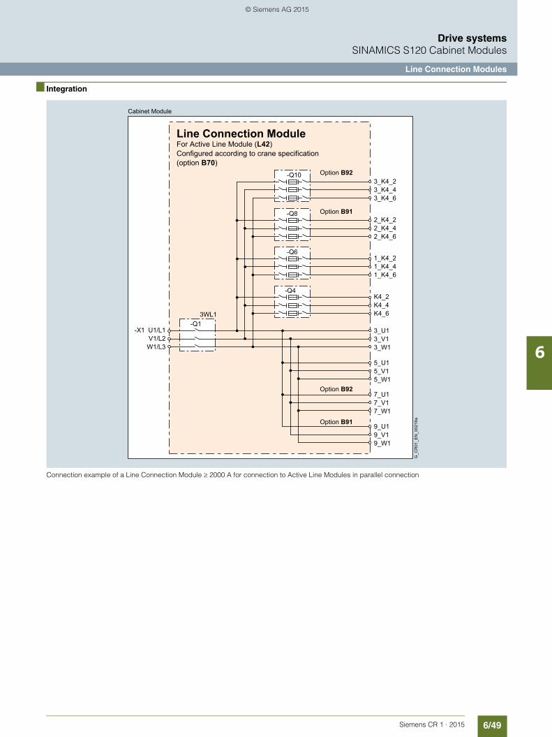
6/49Siemens CR 1 · 2015
6
Drive systemsSINAMICS S120 Cabinet Modules
Line Connection Modules
■ Integration
Connection example of a Line Connection Module ≥ 2000 A for connection to Active Line Modules in parallel connection
Line Connection ModuleFor Active Line Module (L42)Configured according to crane specification(option B70)
G_C
R01
_EN
_002
16a
Option B92
Option B91
-Q10
Option B91-Q8
1_K4_21_K4_41_K4_6
Option B92
-Q6
K4_2K4_4K4_6
3_U13_V13_W1
5_U15_V15_W1
7_U17_V17_W1
9_U19_V19_W1
-X1 U1/L1V1/L2W1/L3
-Q4
-Q13WL1
3_K4_23_K4_43_K4_6
2_K4_22_K4_42_K4_6
Cabinet Module
© Siemens AG 2015

6/50 Siemens CR 1 · 2015
6
Drive systemsSINAMICS S120 Cabinet Modules
Line Connection Modules
■ Technical specifications
Line voltage
380 … 480 V 3 AC
Line Connection Module
Type
6SL3700-0LE41-3AA3
6SL3700-0LE41-6AA3
6SL3700-0LE42-0BA3
6SL3700-0LE43-2BA3
6SL3700-0NE44-0BA3
6SL3700-0NE46-3BA3
Prepared for connection to Line Modules connected in parallel
Infeed/regenerative feedback current• Rated current Irated E A 1250 1600 2000 3200 4000 6300
Power requirement• 24 V DC aux. power supply A – – – – – –• 230 V 2 AC A 1.07 1.07 2.14 2.14 4 4
Power loss, max. 1)
• at 50 Hz 400 V- Option L42/L44 kW 0.29 0.41 0.6 0.95 1.8 1.8
• at 60 Hz 460 V- Option L42/L44 kW 0.29 0.41 0.6 0.95 1.8 1.8
Sound pressure level LpA(1 m) at 50/60 Hz
dB 68/70 68/70 70/72 70/72 72/74 72/74
Line supply connection L1, L2, L3 5/M12 + 4/M16 5/M12 + 4/M16 5/M12 + 4/M16 5/M12 + 4/M16 64/M12 64/M12• Conductor cross-section, max. (IEC) mm2 10 × 240 10 × 240 10 × 240 10 × 240 64 × 240 64 × 240
PE/GND connection PE bar PE bar PE bar PE bar PE bar PE bar• Busbar cross-section mm2 600 600 600 600 600 600• Conductor cross-section, max. (IEC) mm2 240 240 240 240 240 240
Degree of protection IP20 IP20 IP20 IP20 IP20 IP20
Dimensions• Width with option B70 mm 1000 1000 1000 1000 1200 1200• Height 2) mm 2200 2200 2200 2200 2200 2200• Depth mm 600 600 600 600 600 600
Weight, approx.• Option L42/L44 kg 470 490 620 720 1100 1100
Frame size JL JL KL LL – –
1) The specified power loss represents the maximum value at 100 % utilization. The value is lower under normal operating conditions.
2) The cabinet height increases by 250 mm with IP21 degree of protection, and by 400 mm with IP23 degree of protection.
© Siemens AG 2015

6/51Siemens CR 1 · 2015
6
Drive systemsSINAMICS S120 Cabinet Modules
Line Connection Modules
■ Selection and ordering data
Line Connection Modules Active Line ModulesCurrent 1) Article No. Number of
Active Line Modules connected in parallel
Total rated current
Total rated output
Typewith order code B70 for Cranes industy version and order code L42for operation on Active Line Modules. 2)
Line voltage 380 … 480 V 3 AC1250 6SL3700-0LE41-3AA3-Z
B70+L422 931 570 2 × 6SL3730-7TE35-0BA31 985 570 6SL3730-7TE41-0BA3
1600 6SL3700-0LE41-6AA3-ZB70+L42
1 1405 900 6SL3730-7TE41-4BA32 1596 950 1 × 6SL3730-7TE38-4BA3
1 × 6SL3730-7TE38-4BA3-Z B912000 6SL3700-0LE42-0BA3-Z
B70+L422 1871 1197 1 × 6SL3730-7TE41-0BA3
1 × 6SL3730-7TE41-0BC33200 6SL3700-0LE43-2BA3-Z
B70+L422 2669 1710 1 × 6SL3730-7TE41-4BA3
1 × 6SL3730-7TE41-4BC33 2807 1795 2 × 6SL3730-7TE41-0BA3
1 × 6SL3730-7TE41-0BC3or1 × 6SL3730-7TE41-0BA32 × 6SL3730-7TE41-0BC3
4000 6SL3700-0NE44-0BA3-ZB70+L42
4 3740 2394 2 × 6SL3730-7TE41-0BA32 × 6SL3730-7TE41-0BC3
3 4000 2565 2 × 6SL3730-7TE41-4BA31 × 6SL3730-7TE41-4BC3or1 × 6SL3730-7TE41-4BA32 × 6SL3730-7TE41-4BC3
6300 6SL3700-0NE46-3BA3-ZB70+L42
4 5340 3420 2 × 6SL3730-7TE41-4BA32 × 6SL3730-7TE41-4BC3
1) The current values listed are based on an ambient temperature (air intake temperature) of 40 °C.
2) For further special versions with order codes, see "Options".
© Siemens AG 2015

6/52 Siemens CR 1 · 2015
6
Drive systemsSINAMICS S120 Cabinet Modules
Line Connection Modules
■ Options
The table below lists the options available for Line Connection Modules (for details, refer to the section "Description of the options"):
Certain options may be mutually exclusive.
Inadmissible option combinations:• M21 (IP21 degree of protection) and M23 (IP23 degree of
protection)• Y31, Y32, Y33 (1, 2 or 4-line label for plant identification)
Brief description of options Additional identifica-tion code -Z with order code and plain text if required
Cranes industry version B70Indicator for supply system variables B81Transformer fuse for 350 kVA transformer output B82Surge arrester 600 V B83Additional connection for left of Active Line Module B91Additional connection for right of Active Line Module B92Withdrawable circuit breaker in place of a fixed-mounted circuit breaker L25Line Connection Modules for Active Line Modules L42EMERGENCY OFF pushbutton in cabinet door L45Cabinet anti-condensation heating L55Insulation monitoring L87Base 100 mm high, RAL 7022 M06Cable compartment 200 mm high, RAL 7035 M07IP21 degree of protection M21IP23 degree of protection (includes M60) M23Side panel (left) M27Additional touch protection (included in M23) M60EMC shield bus M70DC busbar system (Id = 1170 A, 1 × 60 × 10 mm) M80DC busbar system (Id = 1500 A, 1 × 80 × 10 mm) M81DC busbar system (Id = 1840 A, 1 × 100 × 10 mm) M82DC busbar system (Id = 2150 A, 2 × 60 × 10 mm) M83DC busbar system (Id = 2730 A, 2 × 80 × 10 mm) M84DC busbar system (Id = 3320 A, 2 × 100 × 10 mm) M85DC busbar system (Id = 3720 A, 3 × 80 × 10 mm) M86DC busbar system (Id = 4480 A, 3 × 100 × 10 mm) M87Crane transport assembly (top-mounted) M90Special paint finish for cabinet Y09 • and
special color RAL ....Assembly into transport units at factory Y11 • and
identification codeLabel for plant identification, 1-line, 40 × 80 mm Y31 • and
identification codeLabel for plant identification, 2-line, 40 × 180 mm Y32 • and
identification codeLabel for plant identification, 4-line, 40 × 180 mm Y33 • and
identification codeCustomer documentation (circuit diagram, terminal diagram, layout diagram) in DXF format D02
© Siemens AG 2015

6/53Siemens CR 1 · 2015
6
■ Options (continued)
Drive systemsSINAMICS S120 Cabinet Modules
Line Connection Modules
Electrical options
DC busbar system mechanical options (busbars between indivi-dual Cabinet Modules)
M80 M81 M82 M83 M84 M85 M86 M87
M80 – – – – – –
M81 – – – – –
M82 – – – – –
M83 – – – – – –
M84 – – – – –
M85 – – – – –
M86 – – – – –
M87 – – – – –
Combination possible
– Combination not possible
© Siemens AG 2015

6/54 Siemens CR 1 · 2015
6
Drive systemsSINAMICS S120 Cabinet Modules
Active Line Modules including Active Interface Modules
■ Overview
Active Line Modules can supply energy and return regenerative energy to the supply system.
Active Line Modules generate a regulated DC voltage that is kept consistent regardless of fluctuations in the line voltage (the line voltage must range within the permissible tolerances). Active Line Modules draw a virtually sinusoidal current from the supply system and therefore do not cause any harmful current harmonics.
A Braking Module and braking resistor are required only if the drives need to be decelerated in a controlled manner after a power failure – i.e. if energy cannot be recovered to the supply.For further information about these components, see Catalog D 21.3.Up to 4 identical Active Line Modules can be connected in par-allel to increase the power and to provide a redundant configu-ration.
Active Line Modules are available for the following voltages and power ratings:
■ Design
Active Line Modules are always operated together with an Active Interface Module, which contains the associated Clean Power Filter and pre-charging circuit. The integrated line filter ensures compliance with the EMC requirements for the "second environ-ment".
The Active Line Module and Active Interface Module are sup-plied as a complete, fully wired unit, i.e., the customer does not need to supply any further cables or carry out any other wiring tasks.
Parallel connection of Active Line Modules to increase power rating
For configuring a drive line-up with higher outputs, Active Line Modules are available, which can be operated in pa-rallel on a common Line Connection Module. Up to 4 identical Active Line Modules can be arranged to the left and right of the Line Connection Module. Up to 2 Active Line Modules each can be arranged on the left and right.
The power connections on the Active Line Module on the left of the Line Connection Module are a mirror image (Article No. with
"C" in the next to last position, example: 6SL3730-7T.41.-.BC3), which results in a very compact design for the line infeed.
If a second Active Line Module has to be arranged on the left side, the option B91 must be specified for the version "2nd parallel infeed on left". If a second Active Line Module has to be arranged on the right side, the option B92 must be speci-fied for the version "2nd parallel infeed on right".
Please note that only Active Line Modules with exactly the same power rating may be connected in parallel. The potential for im-balances in current distribution means that a current derating of 5 % applies; this must be taken into account when the modules are dimensioned.
When configuring, it must be ensured that the maximum DC link capacitance for the drive line-up that can be charged through the Active Line Modules is not exceeded.
A connection of the Active Line Modules in parallel using DRIVE-CLiQ must be taken into consideration.
For additional information, please refer to the SINAMICS Low Voltage Engineering Manual.
Line voltage Rated output
380 … 480 V 3 AC 300 … 900 kW (power can be increased to up to 3420 kW through parallel connection)
MotorModule
MotorModule
MotorModule
DC busbar
Motor feederMotor feeder Infeed
ActiveLine
Module
ActiveLine
Module
G_CR01_EN_00217
ActiveLine
Module
ActiveLine
Module
ActiveInterfaceModule
ActiveInterfaceModule
ActiveInterfaceModule
ActiveInterfaceModule
LineConnec-
tionModule
6SL3730-7T...-.BC3 6SL3730-7T...-.BC3B91
6SL3730-7T...-.BA3B92
6SL3730-7T...-.BA3Option B91+ B92
© Siemens AG 2015

6/55Siemens CR 1 · 2015
6
Drive systemsSINAMICS S120 Cabinet Modules
Active Line Modules including Active Interface Modules
■ Integration
The Active Line Module is controlled by the CU320-2 Control Unit. Data is exchanged between the Control Unit and Module via the DRIVE-CLiQ connections. The Active Interface Module is included in the scope of delivery for the Active Line Module.
Example of connection of an Active Line Module (frame sizes GI/GX)
P24L P24L
4321-X42
MM
Internal power supply
Bypass contactor control
DC busbar
Connection for Braking Module
Fan
Gating Pre-charge contactor
DR
IVE
-CLi
Q s
ocke
t 0
DR
IVE
-CLi
Q s
ocke
t 1
DR
IVE
-CLi
Q s
ocke
t 2
Bypass contactor
Pre-charge contactor
Contactors open
Fan
ActiveLine Module Configured according to crane specification (option B70)
Auxiliary power supply24 V DC
L1/L2 operating voltage380 - 480 V AC
Feedback of pre-charge
G_CR01_EN_00328
L1 / L2 operating voltageAC 230 V
Configured according to crane specification (option B70)
For Active Line Module (L42) Configured according to crane specification
DR
IVE
-CLi
Q s
ocke
t
Connection set at factory between Active Infeed Module and Active Line Module
Cabinet Module
=
~
==
PEW1V1U1 -X1
DCNADCPA
DCNDCP
1EP M24 V+EP
MP24 V
2
1
1234-X41
654321-X9
3X400 X401 X402
Cabinet Module
PEW2V2U2
-X2
Active Interface Module
Voltage Sensing Module VSM
LEDRDY
3X500
PEW1V1U1T3T2T1
-X1
MM
24P24P
14131211109876543
2
1
21PE-X609
-F102
-F101
-F11
-F10
IPD Card
DC LINK POWER OK
READY
LED
sTemp-Temp+
-X3
-X1
Line ConnectionModule
Cabinet Module
K4_2K4_4K4_6
1_K4_21_K4_41_K4_6
-Q6
-X1U1/L
1V1/L2W1/L3
-Q4
-Q13WL1
PE
-X3
-X2
≈
1
2
3
© Siemens AG 2015

6/56 Siemens CR 1 · 2015
6
■ Integration (continued)
Drive systemsSINAMICS S120 Cabinet Modules
Active Line Modules including Active Interface Modules
Example of connection of an Active Line Module (frame sizes HI/HX and JI/JX)
DR
IVE
-CLi
Q s
ocke
t 0
DR
IVE
-CLi
Q s
ocke
t
DR
IVE
-CLi
Q s
ocke
t 1
DR
IVE
-CLi
Q s
ocke
t 2
for Active Line Module (L42)Configured according to crane specification
Line ConnectionModule Bypass contactor
control
DC busbar
Connection forBraking Module
Pre-charge contactor
Contactors open
Fan
Active Interface Module
GatingPre-charge contactor
ActiveLine Module Configuredaccording to cranespecification(option B70)
Configuredaccording to cranespecification(option B70)
Auxiliary power supply24 V DCConnection set at factory between
Active Infeed Module and Active Line Module
G_CR01_EN_00218
Feedback of pre-charge
L1/L2 operating voltage230 V AC
No. of fans depending on frame size
Fan
L1/L2 operating voltage 380 - 480 V AC
Cabinet ModuleCabinet Module
Cabinet Module
2_K4_22_K4_42_K4_6
3_K4_23_K4_43_K4_6
-Q10
-X3
-X2
-X1U1/L
1V1/L2W1/L3
PE
-Q8
-Q13WL1
X402X401X400
DCNADCPA
DCNDCP
EP M1+24 VEP
MP24 V
-F21
-F20
-F11
-F10
L2L1
-X1
-X3
-X1
-X9
PEW2V2U2-X2
W1V1U1
1
2
X500
1234-X41
654321-X9
-F102
-F101MMP24P24
2
1
T3T2T1
PEL3L2L1 -X1
N
L
1413121110987654321PE-X609
LEDRDY
Module VSM
Voltage Sensing
© Siemens AG 2015

6/57Siemens CR 1 · 2015
6
Drive systemsSINAMICS S120 Cabinet Modules
Active Line Modules including Active Interface Modules
■ Technical specifications
Line voltage 380 … 480 V 3 AC Active Line Module
Type
6SL3730-7TE35-0BA3 6SL3730-7TE38-4BA3 6SL3730-7TE41-0BA3 6SL3730-7TE41-4BA3
For parallel connection, mounted to the left of the Line Connection Module
6SL3730-7TE41-0BC3 6SL3730-7TE41-4BC3
Rated output• at Irated DC (50 Hz 400 V) kW 300 500 630 900• at IH DC (50 Hz 400 V) kW 270 465 545 780• at Irated DC (60 Hz 460 V) hp 500 700 900 1250• at IH DC (60 Hz 460 V) hp 400 700 800 1000
DC link current• Rated current Irated DC A 549 940 1103 1574• Base-load current IH DC
1) A 489 837 982 1404• Maximum current Imax DC A 823 1410 1654 2361
Infeed/regenerative feedback current• Rated current Irated E A 490 840 985 1405• Maximum current Imax E A 735 1260 1477 2107
Power requirement• 24 V DC aux. power supply A 1.52 1.57 1.67 1.67• 400 V AC A 1.8 3.6 5.4 5.4
DC link capacitance• Active Line Module μF 9600 16800 18900 28800• Drive line-up, max. μF 76800 134400 230400 230400
Power loss, max. 2)
• at 50 Hz 400 V kW 8.7 13.8 17.6 21.8• at 60 Hz 460 V kW 9.0 14.3 18.3 22.7
Cooling air requirement m3/s 1.3 1.58 1.88 1.88
Sound pressure level LpA3)
(1 m) at 50/60 HzdB 72/74 77/79 78/80 78/80
PE/GND connection PE bar PE bar PE bar PE bar• Busbar cross-section mm2 600 600 600 600• Conductor cross-section, max. (IEC) mm2 240 240 240 240
Cable length, max. 4)
• Shielded m 2700 3900 3900 3900• Unshielded m 4050 5850 5850 5850
Degree of protection IP20 IP20 IP20 IP20
Dimensions• Width with option B70 mm 1000 1200 1600 1600• Height 5) mm 2200 2200 2200 2200• Depth mm 600 600 600 600
Weight, approx. kg 530 930 1360 1360
Frame size GX + GI HX + HI JX + JI JX + JI
1) The base-load current IH DC is based on a duty cycle of 150 % for 60 sor Imax DC for 5 s with a duty cycle duration of 300 s.
2) The specified power loss represents the maximum value at 100 % utiliza-tion. The value is lower under normal operating conditions.
3) Total sound pressure level of Active Interface Module and Active Line Module.
4) Total of all motor cables and DC link. Longer cable lengths for specific configurations are available on request.
5) The cabinet height increases by 250 mm with IP21 degree of protection, and by 400 mm with IP23 degree of protection.
© Siemens AG 2015
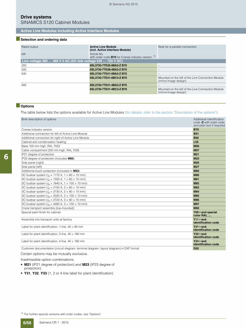
6/58 Siemens CR 1 · 2015
6
Drive systemsSINAMICS S120 Cabinet Modules
Active Line Modules including Active Interface Modules
■ Selection and ordering data
■ Options
The table below lists the options available for Active Line Modules (for details, refer to the section "Description of the options"):
Certain options may be mutually exclusive.
Inadmissible option combinations:• M21 (IP21 degree of protection) and M23 (IP23 degree of
protection)• Y31, Y32, Y33 (1, 2 or 4-line label for plant identification)
Rated output Active Line Module (incl. Active Interface Module)
Note for a parallel connection
kW Article No.with order code B70 for Cranes industry version. 1)
Line voltage 380 … 480 V 3 AC (DC link voltage 540 … 720 V DC)300 6SL3730-7TE35-0BA3-Z B70 –500 6SL3730-7TE38-4BA3-Z B70 –630 6SL3730-7TE41-0BA3-Z B70 –
6SL3730-7TE41-0BC3-Z B70 Mounted on the left of the Line Connection Module(mirror-image design)
900 6SL3730-7TE41-4BA3-Z B70 –6SL3730-7TE41-4BC3-Z B70 Mounted on the left of the Line Connection Module
(mirror-image design)
1) For further special versions with order codes, see "Options".
Brief description of options Additional identification code -Z with order code and plain text if required
Cranes industry version B70Additional connection for left of Active Line Module B91Additional connection for right of Active Line Module B92Cabinet anti-condensation heating L55Base 100 mm high, RAL 7022 M06Cable compartment 200 mm high, RAL 7035 M07IP21 degree of protection M21IP23 degree of protection (includes M60) M23Side panel (right) M26Side panel (left) M27Additional touch protection (included in M23) M60DC busbar system (Id = 1170 A, 1 × 60 × 10 mm) M80DC busbar system (Id = 1500 A, 1 × 80 × 10 mm) M81DC busbar system (Id = 1840 A, 1 × 100 × 10 mm) M82DC busbar system (Id = 2150 A, 2 × 60 × 10 mm) M83DC busbar system (Id = 2730 A, 2 × 80 × 10 mm) M84DC busbar system (Id = 3320 A, 2 × 100 × 10 mm) M85DC busbar system (Id = 3720 A, 3 × 80 × 10 mm) M86DC busbar system (Id = 4480 A, 3 × 100 × 10 mm) M87Crane transport assembly (top-mounted) M90Special paint finish for cabinet Y09 • and special
color RAL ....Assembly into transport units at factory Y11 • and
identification codeLabel for plant identification, 1-line, 40 × 80 mm Y31 • and
identification codeLabel for plant identification, 2-line, 40 × 180 mm Y32 • and
identification codeLabel for plant identification, 4-line, 40 × 180 mm Y33 • and
identification codeCustomer documentation (circuit diagram, terminal diagram, layout diagram) in DXF format D02
© Siemens AG 2015

6/59Siemens CR 1 · 2015
6
■ Options (continued)
Drive systemsSINAMICS S120 Cabinet Modules
Active Line Modules including Active Interface Modules
DC busbar system mechanical options (busbars between individual Cabinet Modules)
M80 M81 M82 M83 M84 M85 M86 M87
M80 – – – – – –
M81 – – – – –
M82 – – – – –
M83 – – – – – –
M84 – – – – –
M85 – – – – –
M86 – – – – –
M87 – – – – –
Combination possible
– Combination not possible
© Siemens AG 2015

6/60 Siemens CR 1 · 2015
6
Drive systemsSINAMICS S120 Cabinet Modules
Motor Modules in chassis format
■ Overview
Motor Modules in chassis format are available in the output range from 110 kW to 800 kW.
■ Design
Motor Modules in chassis format contain the following compo-nents as standard:• Retaining device for the DC busbar, including the connection
to the DC connections of the Motor Module• Nickel-plated connection busbars for motor cables for
Motor Modules, frame sizes FX and GX; connection is made directly on the unit for Motor Modules, frame sizes HX and JX.
• Cable clamping bar for the power cables• DRIVE-CLiQ interface (3 DRIVE-CLiQ sockets), without
Control Unit• Customer interface -X55• Nickel-plated PE busbar (60 x 10 mm), including jumper for
looping through to the next Cabinet Module• EMC-compliant design thanks to additional shielding measu-
res and appropriate cable routing
Line voltage DC link voltage Type rating
380 … 480 V 3 AC 510 … 720 V DC 110 … 800 kW
© Siemens AG 2015

6/61Siemens CR 1 · 2015
6
Drive systemsSINAMICS S120 Cabinet Modules
Motor Modules in chassis format
■ Integration
Motor Modules are controlled by the CU320-2 DP or CU320-2 PN Control Unit. Communication takes place over the DRIVE-CLiQ connection. The Control Units and the DRIVE-CLiQ cable are not included in the scope of supply and must be configured by the customer.
Connection example of a Motor Module
=
=
Internal
Internalpowersupply
DR
IVE
-CLi
Q s
ocke
t 0
DR
IVE
-CLi
Q s
ocke
t 1
DR
IVE
-CLi
Q s
ocke
t 2
G_C
R01
_EN
_002
19a
LED
s
Motor ModuleConfigured according to crane specification (option B70)
Fan
Fan Number of fansdepends on thesize
Customer terminal block
DC busbar
24 V DCAuxiliary voltage
supply
L1/L2 operating voltage380 - 480 V AC
Cabinet Module
M3 ~
EP +24 V EP M1 M
- TempTemp+
1234-X41
DCNSDCPS
DCNADCPA
DCNDCP
-F21
-F20-F11
-F10
~
=
L2L1
M
5 6
3 4
1 2
W2V2
PE
U2 -X2
-X9P24 V
-X55
-X3
-X1
X401X400 X402
© Siemens AG 2015

6/62 Siemens CR 1 · 2015
6
Drive systemsSINAMICS S120 Cabinet Modules
Motor Modules in chassis format
■ Technical specifications
Line voltage 380 … 480 V 3 ACDC link voltage 510 … 720 V DC
Motor Module in chassis formatType6SL3720-1TE32-1AA3
6SL3720-1TE32-6AA3
6SL3720-1TE33-1AA3
6SL3720-1TE33-8AA3
6SL3720-1TE35-0AA3
6SL3720-1TE36-1AA3
Type rating• at IL (50 Hz 400 V) 1) kW 110 132 160 200 250 315• at IH (50 Hz 400 V) 1) kW 90 110 132 160 200 250• at IL (60 Hz 460 V) 2) hp 150 200 250 300 400 500• at IH (60 Hz 460 V) 2) hp 150 200 200 250 350 350Output current• Rated current Irated A A 210 260 310 380 490 605• Base-load current IL
3) A 205 250 302 370 477 590• Base-load current IH
4) A 178 233 277 340 438 460• Maximum current Imax A A 307 375 453 555 715 885DC link current• Rated current Irated DC
when supplied from- Basic/Smart Line Module A 252 312 372 456 588 726- Active Line Module A 227 281 335 411 529 653
• Base-load current IL DC3)
when supplied from- Basic/Smart Line Module A 245 304 362 444 573 707- Active Line Module A 221 273 326 400 515 636
• Base-load current IH DC 4)
when supplied from- Basic/Smart Line Module A 224 277 331 405 523 646- Active Line Module A 202 250 298 365 470 581
Power requirement• 24 V DC aux. power supply A 0.8 0.8 0.9 0.9 0.9 1.0• 400 V AC A 0.63 1.13 1.8 1.8 1.8 3.6DC link capacitance μF 4200 5200 6300 7800 9600 12600Pulse frequency 5)
• Rated frequency kHz 2 2 2 2 2 1.25• Pulse frequency, max.
- without current derating Hz 2 2 2 2 2 1.25- with current derating Hz 8 8 8 8 8 7.5
Power loss, max. 6)
• at 50 Hz 400 V kW 1.86 2.5 2.96 3.67 4.28 5.84• at 60 Hz 460 V kW 1.94 2.6 3.1 3.8 4.5 6.3Cooling air requirement m3/s 0.17 0.23 0.36 0.36 0.36 0.78Sound pressure level LpA(1 m) at 50/60 Hz
dB 67 69 69 69 69 72
Motor connectionU2, V2, W2
M12 screws M12 screws M12 screws M12 screws M12 screws M12 screws
• Conductor cross-section, max. (IEC) mm2 2 × 185 2 × 185 2 × 240 2 × 240 2 × 240 4 × 240Cable length, max. 7)
• Shielded m 300 300 300 300 300 300• Unshielded m 450 450 450 450 450 450PE/GND connection PE bar PE bar PE bar PE bar PE bar PE bar• Busbar cross-section mm2 600 600 600 600 600 600• Conductor cross-section, max. (IEC) mm2 240 240 240 240 240 240Degree of protection IP20 IP20 IP20 IP20 IP20 IP20Dimensions• Width mm 400 400 400 400 400 600• Height 8) mm 2200 2200 2200 2200 2200 2200• Depth mm 600 600 600 600 600 600Weight, approx. kg 145 145 286 286 286 490Frame size FX FX GX GX GX HX
1) Rated power of a typ. 6-pole standard induction motor based on IL or IH at 400 V 3 AC 50 Hz.
2) Rated power of a typ. 6-pole standard induction motor based on IL or IH at 460 V 3 AC 60 Hz.
3) The base-load current IL is based on a duty cycle of 110 % for 60 s or 150 % for 10 s with a duty cycle duration of 300 s.
4) The base-load current IH is based on a duty cycle of 150 % for 60 s or 160 % for 10 s with a duty cycle duration of 300 s.
5) For details of the relationship between pulse frequency and maximum output current/output frequency, see Catalog PM 21.
6) The specified power loss represents the maximum value at 100 % capacity utilization. The value is lower under normal operating conditions.
7) Total of all motor cables. Longer cable lengths for specific configurations are available on request. See also SINAMICS Low Voltage Engineering Manual.
8) The cabinet height increases by 250 mm with IP21 degree of protection, and by 400 mm with IP23 degree of protection.
© Siemens AG 2015

6/63Siemens CR 1 · 2015
6
■ Technical specifications (continued)
Drive systemsSINAMICS S120 Cabinet Modules
Motor Modules in chassis format
Line voltage 380 … 480 V 3 AC
DC link voltage 510 … 720 V DC
Motor Modules in chassis formatType6SL3720-1TE37-5AA3
6SL3720-1TE38-4AA3
6SL3720-1TE41-0AA3
6SL3720-1TE41-2AA3
6SL3720-1TE41-4AA3
Type rating• at IL (50 Hz 400 V) 1) kW 400 450 560 710 800• at IH (50 Hz 400 V) 1) kW 315 400 450 560 710• at IL (60 Hz 460 V) 2) hp 600 700 800 1000 1150• at IH (60 Hz 460 V) 2) hp 450 600 700 900 1000Output current• Rated current Irated A A 745 840 985 1260 1405• Base-load current IL
3) A 725 820 960 1230 1370• Base-load current IH
4) A 570 700 860 1127 1257• Maximum current Imax A A 1087 1230 1440 1845 2055DC link current• Rated current Irated DC
when supplied from- Basic/Smart Line Module A 894 1008 1182 1512 1686- Active Line Module A 805 907 1064 1361 1517
• Base-load current IL DC3)
when supplied from- Basic/Smart Line Module A 871 982 1152 1474 1643- Active Line Module A 784 884 1037 1326 1479
• Base-load current IH DC 4)
when supplied from- Basic/Smart Line Module A 795 897 1051 1345 1500- Active Line Module A 716 807 946 1211 1350
Power requirement• 24 V DC aux. power supply A 1.0 1.0 1.25 1.4 1.4• 400 V AC A 3.6 3.6 5.4 5.4 5.4DC link capacitance μF 15600 16800 18900 26100 28800Pulse frequency 5)
• Rated frequency kHz 1.25 1.25 1.25 1.25 1.25• Pulse frequency, max.
- without current derating kHz 1.25 1.25 1.25 1.25 1.25- with current derating kHz 7.5 7.5 7.5 7.5 7.5
Power loss, max. 6)
• at 50 Hz 400 V kW 6.68 7.15 9.5 11.1 12• at 60 Hz 460 V kW 7.3 7.8 10.2 12.0 13Cooling air requirement m3/s 0.78 0.78 1.1 1.1 1.1Sound pressure level LpA(1 m) at 50/60 Hz
dB 72 72 72 72 72
Motor connectionU2, V2, W2
M12 screws M12 screws M12 screws M12 screws M12 screws
• Conductor cross-section, max. (IEC) mm2 4 × 240 4 × 240 6 × 240 6 × 240 6 × 240Cable length, max. 7)
• Shielded m 300 300 300 300 300• Unshielded m 450 450 450 450 450PE/GND connection PE bar PE bar PE bar PE bar PE bar• Busbar cross-section mm2 600 600 600 600 600• Conductor cross-section, max. (IEC) mm2 240 240 240 240 240Degree of protection IP20 IP20 IP20 IP20 IP20Dimensions• Width mm 600 600 800 800 800• Height 8) mm 2200 2200 2200 2200 2200• Depth mm 600 600 600 600 600Weight, approx. kg 490 490 700 700 700Frame size HX HX JX JX JX
1) Rated power of a typ. 6-pole standard induction motor based on IL or IH at 400 V 3 AC 50 Hz.
2) Rated power of a typ. 6-pole standard induction motor based on IL or IH at 460 V 3 AC 60 Hz.
3) The base-load current IL is based on a duty cycle of 110 % for 60 s or 150 % for 10 s with a duty cycle duration of 300 s.
4) The base-load current IH is based on a duty cycle of 150 % for 60 s or 160 % for 10 s with a duty cycle duration of 300 s.
5) For details of the relationship between pulse frequency and maximum out-put current/output frequency, see Catalog PM 21.
6) 6) The specified power loss represents the maximum value at 100 % capa-city utilization. The value is lower under normal operating conditions.
7) 7) Total of all motor cables. Longer cable lengths for specific configura-tions are available on request. See also SINAMICS Low Voltage Enginee-ring Manual.
8) The cabinet height increases by 250 mm with IP21 degree of protection, and by 400 mm with IP23 degree of protection.
© Siemens AG 2015

6/64 Siemens CR 1 · 2015
6
Drive systemsSINAMICS S120 Cabinet Modules
Motor Modules in chassis format
■ Selection and ordering data
Type rating Rated output current Irated
Motor Modules in chassis format
kW A
Article No.with order code B70 for Cranes industry version. 1)
Line voltage 380 … 480 V 3 AC (DC link voltage 510 … 720 V DC)
110 210 6SL3720-1TE32-1AA3-Z B70
132 260 6SL3720-1TE32-6AA3-Z B70
160 310 6SL3720-1TE33-1AA3-Z B70
200 380 6SL3720-1TE33-8AA3-Z B70
250 490 6SL3720-1TE35-0AA3-Z B70
315 605 6SL3720-1TE36-1AA3-Z B70
400 745 6SL3720-1TE37-5AA3-Z B70
450 840 6SL3720-1TE38-4AA3-Z B70
560 985 6SL3720-1TE41-0AA3-Z B70
710 1260 6SL3720-1TE41-2AA3-Z B70
800 1405 6SL3720-1TE41-4AA3-Z B70
1) For further special versions with order codes, see "Options".
© Siemens AG 2015

6/65Siemens CR 1 · 2015
6
Drive systemsSINAMICS S120 Cabinet Modules
Motor Modules in chassis format
■ Options
The table below lists the options available for Motor Modules (for details, refer to the section "Description of the options"):
Certain options may be mutually exclusive.
Inadmissible option combinations:• M21 (IP21 degree of protection) and M23 (IP23 degree of protection)• Y31, Y32, Y33 (1, 2 or 4-line label for plant identification)
DC busbar system mechanical options (busbars between individual Cabinet Modules)
Brief description of options Additional identification code -Z with order code and plain text if required
Cranes industry version B70SMC10 Sensor Module Cabinet-Mounted K46SMC20 Sensor Module Cabinet-Mounted K48SMC30 Sensor Module Cabinet-Mounted K50VSM10 Voltage Sensing Module Cabinet-Mounted K51Terminal module for controlling the Safe Torque Off and Safe Stop 1 safety functions K82Motor reactor L08DC interface incl. pre-charging circuit of the relevant DC link capacitance L37Cabinet anti-condensation heating L55Base 100 mm high, RAL 7022 M06Cable compartment 200 mm high, RAL 7035 M07IP21 degree of protection M21IP23 degree of protection (includes M60) M23Side panel (right) M26Side panel (left) M27Additional touch protection (included in M23) M60EMC shield bus M70DC busbar system (Id = 1170 A, 1 × 60 × 10 mm) M80DC busbar system (Id = 1500 A, 1 × 80 × 10 mm) M81DC busbar system (Id = 1840 A, 1 × 100 × 10 mm) M82DC busbar system (Id = 2150 A, 2 × 60 × 10 mm) M83DC busbar system (Id = 2730 A, 2 × 80 × 10 mm) M84DC busbar system (Id = 3320 A, 2 × 100 × 10 mm) M85DC busbar system (Id = 3720 A, 3 × 80 × 10 mm) M86DC busbar system (Id = 4480 A, 3 × 100 × 10 mm) M87Crane transport assembly (top-mounted) M90Special paint finish for cabinet Y09 • and special
color RAL ....Assembly into transport units at factory Y11 • and
identification codeLabel for plant identification, 1-line, 40 × 80 mm Y31 • and
identification codeLabel for plant identification, 2-line, 40 × 180 mm Y32 • and
identification codeLabel for plant identification, 4-line, 40 × 180 mm Y33 • and
identification codeCustomer documentation (circuit diagram, terminal diagram, layout diagram) in DXF format D02
M80 M81 M82 M83 M84 M85 M86 M87
M80 – – – – – –
M81 – – – – –
M82 – – – – –
M83 – – – – – –
M84 – – – – –
M85 – – – – –
M86 – – – – –
M87 – – – – –
Combination possible
– Combination not possible
© Siemens AG 2015

6/66 Siemens CR 1 · 2015
6
Drive systemsSINAMICS S120 Cabinet Modules
Motor Double Choke Modules
■ Overview
Motor reactors reduce the voltage stress on the motor windings by reducing the voltage gradients at the motor terminals that oc-cur when motors are fed from drive converters. At the same time, the capacitive charge/discharge currents that occur at the con-verter output when long motor cables are used are reduced. Sui-tably dimensioned motor reactors therefore enable large capa-citances and thus longer motor cables to be connected. Their use is generally recommended in the case of multi-motor drives. With option L08 for Motor Modules, a motor reactor is integrated into the Motor Module up to cabinet size GX (outputs of less than 315 kW). Due to space constraints, a separate cabinet must be planned for the output range 315 to 450 kW (cabinet size HX).
■ Design
The Motor Double Choke Modules are equipped as standard with 2 identical motor reactors. Two Motor Modules can be con-nected to one Motor Double Choke Module, depending on the type selected.
© Siemens AG 2015

6/67Siemens CR 1 · 2015
6
Drive systemsSINAMICS S120 Cabinet Modules
Motor Double Choke Modules
■ Integration
The Motor Modules connected to the Motor Double Choke Module must be arranged immediately to the left and right of the Motor Double Choke Module.
Connection example of a Motor Double Choke Module
M3 ~
M3 ~
DC busbar
G_C
R01
_EN
_003
26Motor reactor 1 Motor reactor 2
Cabinet Module
Motor Double Choke Module
MotorModule
MotorModule W1 PE
W2V2U2
-X2
-X1.1
-X1.2
PEW2V2U2
-X2
PE
V1U1
W2 PEV2U2
W1 PE-X2.1
-X2.2
V1U1
W2 PEV2U2
© Siemens AG 2015

6/68 Siemens CR 1 · 2015
6
Drive systemsSINAMICS S120 Cabinet Modules
Motor Double Choke Modules
■ Technical specifications
■ Selection and ordering data
Line voltage 380 ... 480 V 3 A Motor Double Choke Module
Type
6SL3700-2AE36-1BA3 6SL3700-2AE38-4BA3
Type rating kW 315 450
Number of reactors 2 2
Rated current Irated E A 605 840
Power loss kW < 2 < 2
Cooling air requirement Convection Convection
Sound pressure level LpA dB – –
Line supply/load connection 2 × M12 2 × M12
Cable length, max.• Shielded m 300 300• Unshielded m 450 450
PE connection PE bar 600 8 × M12
PE bar 600 8 × M12
Degree of protection IP20 IP20
Dimensions• Width mm 600 600• Height mm 220 220• Depth mm 600 600
Weight, approx. kg 420 450
Matching Motor Modules 6SL3720-1TE36-1AA3 6SL3720-1TE37-5AA3
6SL3720-1TE38-4AA3
Type rating Motor Double Choke Module Motor Module in chassis format
kW
Article No.with order code B70for Cranes industry version. 1)
Type
315 6SL3700-2AE36-1BA3-Z B70 6SL3720-1TE36-1AA3
400 6SL3700-2AE38-4BA3-Z B70 6SL3720-1TE37-5AA3
450 6SL3700-2AE38-4BA3-Z B70 6SL3720-1TE38-4AA3
1) For further special versions with order codes, see "Options".
© Siemens AG 2015

6/69Siemens CR 1 · 2015
6
Drive systemsSINAMICS S120 Cabinet Modules
Motor Double Choke Modules
■ Options
The table below lists the options available for Motor Double Choke Modules (for details, refer to the "Description of the options"):
Certain options may be mutually exclusive.
Inadmissible option combinations:• M21 (IP21 degree of protection) and M23 (IP23 degree of
protection)• Y31, Y32, Y33 (1, 2 or 4-line label for plant identification)
DC busbar system mechanical options (busbars between individual Cabinet Modules)
Brief description of options Additional identification code -Z with order code and plain text if required
Cranes industry version B70Cabinet anti-condensation heating L55Base 100 mm high, RAL 7022 M06Cable compartment 200 mm high, RAL 7035 M07IP21 degree of protection M21IP23 degree of protection (includes M60) M23Side panel (right) M26Side panel (left) M27Additional touch protection (included in M23) M60EMC shield bus M70DC busbar system (Id = 1170 A, 1 × 60 × 10 mm) M80DC busbar system (Id = 1500 A, 1 × 80 × 10 mm) M81DC busbar system (Id = 1840 A, 1 × 100 × 10 mm) M82DC busbar system (Id = 2150 A, 2 × 60 × 10 mm) M83DC busbar system (Id = 2730 A, 2 × 80 × 10 mm) M84DC busbar system (Id = 3320 A, 2 × 100 × 10 mm) M85DC busbar system (Id = 3720 A, 3 × 80 × 10 mm) M86DC busbar system (Id = 4480 A, 3 × 100 × 10 mm) M87Crane transport assembly (top-mounted) M90Special paint finish for cabinet Y09 • and special
color RAL ....Assembly into transport units at factory Y11 • and
identification codeLabel for plant identification, 1-line, 40 × 80 mm Y31 • and
identification codeLabel for plant identification, 2-line, 40 × 180 mm Y32 • and
identification codeLabel for plant identification, 4-line, 40 × 180 mm Y33 • and
identification codeCustomer documentation (circuit diagram, terminal diagram, layout diagram) in DXF format D02
M80 M81 M82 M83 M84 M85 M86 M87
M80 – – – – – –
M81 – – – – –
M82 – – – – –
M83 – – – – – –
M84 – – – – –
M85 – – – – –
M86 – – – – –
M87 – – – – –
Combination possible
– Combination not possible
© Siemens AG 2015

6/70 Siemens CR 1 · 2015
6
Drive systemsSINAMICS S120 Cabinet Modules
Motor Multi Connection Modules
■ Overview
If the drive output of a gantry with drive motors is distributed over multiple axes to achieve a more compact design and enhanced motion, these motors can be operated cost-optimized in parallel with a converter with an appropriate total power rating. The Mo-tor Multi Connection Modules are used to protect the individual motors from the total power of the converter. Motor Multi Connec-tion Modules contain the motor circuit breakers. Each motor cir-cuit breaker protects one motor. Several motor circuit breakers are connected in parallel on the input side into a section for con-nection to a Motor Module. The Motor Multi Connection Modules can be equipped with optional analog measuring instruments built into the cabinet door for indicating the current motor cur-rents and current output voltage of the Motor Modules.
■ Design
In total, 4 control cabinet versions are available for connecting 12, 16, 20 or 24 motors with an appropriate number of motor circuit breakers. The motor circuit breakers are designed for a rated current of 45 A to 63 A. The motor circuit breakers are always connected at the input side into 4 groups of 3, 4, 5 or 6 motor circuit breakers for connection to Motor Modules. Up to 2 Motor Modules can be connected to one Motor Multi Connection Module for operating up to 2 sections of motors connected in parallel. As an option, depending on the control cabinet version, 12, 16, 20 or 24 ammeters for indicating the motor currents as well as 2 voltmeters for indicating the output voltages of the Motor Modules can be integrated in the cabinet door of the Motor Multi Connection Module.
© Siemens AG 2015

6/71Siemens CR 1 · 2015
6
Drive systemsSINAMICS S120 Cabinet Modules
Motor Multi Connection Modules
■ Integration
The motors and Motor Modules are connected to the Motor Multi Connection Module in accordance with the grouping.
Connection example of a Motor Multi Connection Module
N = 3, 4, 5, 6
DSNDS1
N = 3, 4, 5, 6
CSNCS1
Motor Multi Connection Module
G_CR01_EN_00211
N = 3, 4, 5, 6
BSNBS1
N = 3, 4, 5, 6
ASNAS1
Cabinet Module
DC busbar
M3 ~
M3 ~
M3 ~
M3 ~
M3 ~
M3 ~
M3 ~
M3 ~
DC
BA
W2 V2 U2 PEPEW2 V2 U2
PEW1 V1 U1
PEW2 V2 U2 PEW2 V2 U2
PEW1 V1 U1
W2 V2 U2 PEPEW2 V2 U2
PEW1 V1 U1
PEW2 V2 U2 PEW2 V2 U2
PEW1 V1 U1
© Siemens AG 2015

6/72 Siemens CR 1 · 2015
6
Drive systemsSINAMICS S120 Cabinet Modules
Motor Multi Connection Modules
■ Technical specifications
■ Selection and ordering data
Ordering example 1
A gantry with 12 motors is to be operated in two sections with 6 motors connected in parallel to one Motor Multi Connection Module.
Selection: Motor Multi Connection Module with 12 motor circuit breakers or 12 connectable motors and the option "Cranes in-dustry version".
Order:6SL3700-2EE34-0AA3-ZB70
Ordering example 2
A gantry with 24 motors is to be operated in two sections with 12 motors connected in parallel to one Motor Multi Connection Module with the ability to control the output voltage and motor currents.
Selection: Motor Multi Connection Module with 24 motor circuit breakers or 24 connectable motors in the "Cranes industry version" with measuring instruments for indicating motor current and voltage in the cabinet door.
Order:6SL3700-2EE34-0DA3-ZB70+B80
Line voltage 380 ... 480 V 3 AC Motor Multi Connection ModuleType6SL3700-2EE34-0AA3-ZB70
6SL3700-2EE34-0BA3-ZB70
6SL3700-2EE34-0CA3-ZB70
6SL3700-2EE34-0DA3-ZB70
Number of motor circuit breakers
12 16 20 24
Rated current per group
A 400 400 400 400
Power loss kW < 1 < 1 < 1 < 1Cooling air requirement Convection Convection Convection ConvectionSound pressure level LpA dB – – – –Line supply/load connec-tion
Screw-type terminal 16 mm2
Screw-type terminal 16 mm2
Screw-type terminal 16 mm2
Screw-type terminal 16 mm2
Cable length, max.• Shielded m 300 300 300 300• Unshielded m 450 450 450 450PE connection PE bar 600
8 × M12PE bar 600 10 × M12
PE bar 600 10 × M12
PE bar 600 10 × M12
Degree of protection IP20 IP20 IP20 IP20Dimensions• Width mm 600 600 800 800• Height mm 2200 2200 2200 2200• Depth mm 600 600 600 600Weight, approx. kg 240 280 290 300
Number of motor circuit breakers
Number of connect-able motors
Motor Multi Connection ModuleArticle No.with order code B70for Cranes industry version. 1)
Option "Measuring instruments in control cabinet door"
Additional identification code -Z with order code
12 12 6SL3700-2EE34-0AA3-Z B70
• 12 ammeters Analog measuring instruments of moving-iron type, 90°scale, 0 ... 60/120 A, direct measuring
B80
• 2 voltmetersAnalog measuring instrument of moving-coil type, 90°scale, 0 ... 520 V, 4 ... 20 mA
16 16 6SL3700-2EE34-0BA3-Z B70
• 16 ammeters Analog measuring instruments of moving-iron type, 90°scale, 0 ... 60/120 A, direct measuring
B80
• 2 voltmetersAnalog measuring instrument of moving-coil type, 90°scale, 0 ... 520 V, 4 ... 20 mA
20 20 6SL3700-2EE34-0CA3-Z B70
• 20 ammeters Analog measuring instruments of moving-iron type, 90°scale, 0 ... 60/120 A, direct measuring
B80
• 2 voltmetersAnalog measuring instrument of moving-coil type, 90°scale, 0 ... 520 V, 4 ... 20 mA
24 24 6SL3700-2EE34-0DA3-Z B70
• 24 ammeters Analog measuring instruments of moving-iron type, 90°scale, 0 ... 60/120 A, direct measuring
B80
• 2 voltmetersAnalog measuring instrument of moving-coil type, 90°scale, 0 ... 520 V, 4 ... 20 mA
1) For further special versions with order codes, see "Options".
© Siemens AG 2015

6/73Siemens CR 1 · 2015
6
Drive systemsSINAMICS S120 Cabinet Modules
Motor Multi Connection Modules
■ Options
The table below lists the options available for Motor Multi Connection Modules (for details, refer to "Description of the options"):
Certain options may be mutually exclusive.
Inadmissible option combinations:• M21 (IP21 degree of protection) and M23 (IP23 degree of
protection)• Y31, Y32, Y33 (1, 2 or 4-line label for plant identification)
DC busbar system mechanical options (busbars between individual Cabinet Modules)
Brief description of options Additional identification code -Z with order code and plain text if required
Cranes industry version B70Measuring instruments in control cabinet door B80Cabinet anti-condensation heating L55Base 100 mm high, RAL 7022 M06Cable compartment 200 mm high, RAL 7035 M07IP21 degree of protection M21IP23 degree of protection (includes M60) M23Side panel (right) M26Side panel (left) M27Additional touch protection (included in M23) M60EMC shield bus M70DC busbar system (Id = 1170 A, 1 × 60 × 10 mm) M80DC busbar system (Id = 1500 A, 1 × 80 × 10 mm) M81DC busbar system (Id = 1840 A, 1 × 100 × 10 mm) M82DC busbar system (Id = 2150 A, 2 × 60 × 10 mm) M83DC busbar system (Id = 2730 A, 2 × 80 × 10 mm) M84DC busbar system (Id = 3320 A, 2 × 100 × 10 mm) M85DC busbar system (Id = 3720 A, 3 × 80 × 10 mm) M86DC busbar system (Id = 4480 A, 3 × 100 × 10 mm) M87Crane transport assembly (top-mounted) M90Special paint finish for cabinet Y09 • and special
color RAL ....Assembly into transport units at factory Y11 • and
identification codeLabel for plant identification, 1-line, 40 × 80 mm Y31 • and
identification codeLabel for plant identification, 2-line, 40 × 180 mm Y32 • and
identification codeLabel for plant identification, 4-line, 40 × 180 mm Y33 • and
identification codeCustomer documentation (circuit diagram, terminal diagram, layout diagram) in DXF format D02
M80 M81 M82 M83 M84 M85 M86 M87
M80 – – – – – –
M81 – – – – –
M82 – – – – –
M83 – – – – – –
M84 – – – – –
M85 – – – – –
M86 – – – – –
M87 – – – – –
Combination possible
– Combination not possible
© Siemens AG 2015
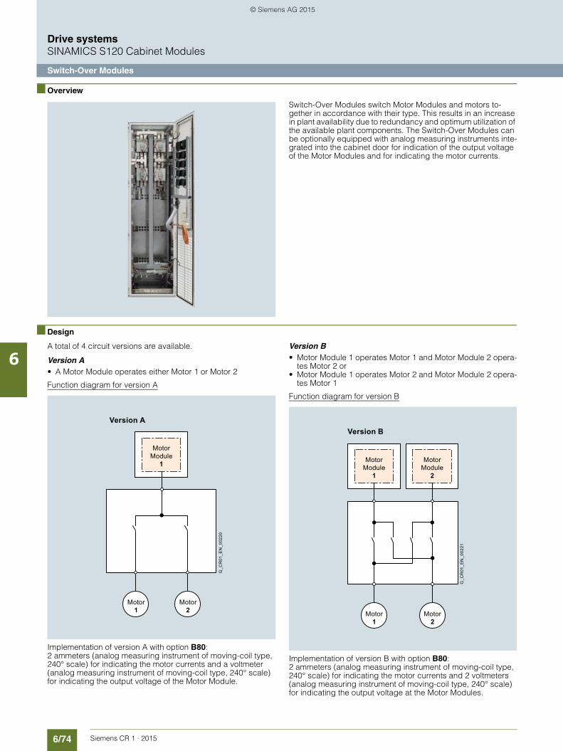
6/74 Siemens CR 1 · 2015
6
Drive systemsSINAMICS S120 Cabinet Modules
Switch-Over Modules
■ Overview
Switch-Over Modules switch Motor Modules and motors to-gether in accordance with their type. This results in an increase in plant availability due to redundancy and optimum utilization of the available plant components. The Switch-Over Modules can be optionally equipped with analog measuring instruments inte-grated into the cabinet door for indication of the output voltage of the Motor Modules and for indicating the motor currents.
■ Design
A total of 4 circuit versions are available.
Version A• A Motor Module operates either Motor 1 or Motor 2
Function diagram for version A
Implementation of version A with option B80: 2 ammeters (analog measuring instrument of moving-coil type, 240° scale) for indicating the motor currents and a voltmeter (analog measuring instrument of moving-coil type, 240° scale) for indicating the output voltage of the Motor Module.
Version B• Motor Module 1 operates Motor 1 and Motor Module 2 opera-
tes Motor 2 or • Motor Module 1 operates Motor 2 and Motor Module 2 opera-
tes Motor 1
Function diagram for version B
Implementation of version B with option B80:2 ammeters (analog measuring instrument of moving-coil type, 240° scale) for indicating the motor currents and 2 voltmeters (analog measuring instrument of moving-coil type, 240° scale) for indicating the output voltage at the Motor Modules.
Version A
G_C
R01
_EN
_002
20
MotorModule
1
Motor1
Motor2
Version B
G_C
R01
_EN
_002
21Motor
Module1
MotorModule
2
Motor1
Motor2
© Siemens AG 2015

6/75Siemens CR 1 · 2015
6
■ Design (continued)
Drive systemsSINAMICS S120 Cabinet Modules
Switch-Over Modules
Version C• Motor Module 1 operates Motor 1.1 and• Motor Module 2 operates Motor 1.2 or• Motor Module 1 operates Motor 2 or• Motor Module 2 operates Motor 2
Function diagram for version C
Implementation of version C with option B80:3 ammeters (analog measuring instrument of moving-coil type, 240° scale) for indicating the motor currents and 2 voltmeters (analog measuring instrument of moving-coil type, 240° scale) for indicating the output voltage at the Motor Modules.
Version D• Motor Module 1 operates Motor 1 or 2 or 3 or 4 and• Motor Module 2 operates a motor other than Motor Module 1
Function diagram for version D
Implementation of version D with option B80:2 ammeters (analog measuring instrument of moving-coil type, 240° scale) for indicating the motor currents and 2 voltmeters (analog measuring instrument of moving-coil type, 240° scale) for indicating the output voltage at the Motor Modules.
The checkback contacts of the individual contactors are con-nected to terminals to support plant-specific interlocks.
Version C
G_C
R01
_EN
_002
22Motor
Module1
MotorModule
2
Motor1.1
Motor2
Motor1.2
Version D
G_C
R01
_EN
_002
23
Motor1
MotorModule
1
MotorModule
2
Motor2
Motor3
Motor4
© Siemens AG 2015

6/76 Siemens CR 1 · 2015
6
Drive systemsSINAMICS S120 Cabinet Modules
Switch-Over Modules
■ Integration
The motors and Motor Modules are connected to the Switch-Over Module in accordance with the grouping.
Version A
Connection example of a Switch-Over Module, Version A
Version B
Connection example of a Switch-Over Module, Version B
Switch-Over ModuleVersion A
DC busbar
G_C
R01
_EN
_002
12
Controlconnections
Feedbackcontacts
U1 PE
W2V2U2
-X2
-X1
-X2
-X3
PE
V1 W1
U2 W2PE PE-X2 -X2V2 V2W2 U2
M3 ~
M3 ~
Cabinet Module
MotorModule
Switch-Over ModuleVersion B
DC busbar
G_C
R01
_EN
_002
13
Controlconnections
Feedbackcontacts
Cabinet Module
MotorModule
MotorModule
W1 PE
W2V2U2
-X2
-X1
-X2
PE
V1U1
W2 PE-X2 -X2V2U2
W2V2U2
-X2
PE
W1 PE-X1-X3
V1U1
W2 PEV2U2
M3 ~
M3 ~
© Siemens AG 2015

6/77Siemens CR 1 · 2015
6
■ Integration (continued)
Drive systemsSINAMICS S120 Cabinet Modules
Switch-Over Modules
Version C
Connection example of a Switch-Over Module, Version C
Switch-Over ModuleVersion C
Cabinet Module
DC busbar
G_C
R01
_EN
_002
14
Controlconnec-tions
FeedbackcontactsMotor
Module MotorModule
W1 PE
W2V2U2
-X2
-X1
-X2
PE
V1U1
W2-X2 -X2 -X2V2U2
W2V2U2
-X2
PE
M3 ~
W1 PE-X1
-X3
V1U1
W2 PEPE V2U2 W2 PEV2U2
M3 ~
M3 ~
© Siemens AG 2015

6/78 Siemens CR 1 · 2015
6
■ Integration (continued)
Drive systemsSINAMICS S120 Cabinet Modules
Switch-Over Modules
Version D
Connection example of a Switch-Over Module, Version D
Switch-Over ModuleVersion D
DC busbar
G_C
R01
_EN
_002
15
Controlconnections
Feedbackcontacts
Feedbackcontacts
Controlconnections
Cabinet Module
MotorModule
MotorModule
W2V2U2
-X2 -X1
-X2
-X2
-X2
-X2
-X2
-X3
-X3
-X2
-X1
PE
W1V1U1
PE
W2V2U2
PE
W2V2U2
-X2
PE
W1V1U1
PE
M3 ~
W2V2U2
PE
M3 ~
W2V2U2
PE
M3 ~
W2V2U2
PE
M3 ~
© Siemens AG 2015

6/79Siemens CR 1 · 2015
6
Drive systemsSINAMICS S120 Cabinet Modules
Switch-Over Modules
■ Technical specifications
Line voltage 380 ... 480 V 3 AC Switch-Over Module
Type
6SL3700-2FE36-1AA3-ZB70
6SL3700-2FE36-1BA3-ZB70
6SL3700-2FE36-1CA3-Z B70
6SL3700-2FE36-1DA3-Z B70
Version A B C D
Number of contactors 2 4 4 8
Rated current A 605 605 605 605
Power loss kW < 1 < 1 < 1 < 1
Cooling air requirement Convection Convection Convection Convection
Sound pressure level LpA dB – – – –
Line supply/load connection 6 × M12 6 × M12 6 × M12 6 × M12
Cable length, max.• Shielded m 300 300 300 300• Unshielded m 450 450 450 450
PE connection PE bar 600 8 × M12
PE bar 600 8 × M12
PE bar 600 8 × M12
PE bar 600 8 × M12
Degree of protection IP20 IP20 IP20 IP20
Dimensions• Width mm 600 600 600 600• Height mm 2200 2200 2200 2200• Depth mm 600 600 600 600
Weight, approx. kg 320 360 380 430
Matching Motor Modules 6SL3720-1TE35-0AA3 6SL3720-1TE35-0AA3 6SL3720-1TE35-0AA3 6SL3720-1TE35-0AA3
6SL3720-1TE36-1AA3 6SL3720-1TE36-1AA3 6SL3720-1TE36-1AA3 6SL3720-1TE36-1AA3
Line voltage 380 ... 480 V 3 AC Switch-Over Module
Type
6SL3700-2FE39-9AA3-Z B70
6SL3700-2FE39-9BA3-Z B70
6SL3700-2FE39-9CA3-Z B70
Version A B C
Number of contactors 4 8 8
Rated current A 985 985 985
Power loss kW < 1 < 2 < 2
Cooling air requirement Convection Convection Convection
Sound pressure level LpA dB – – –
Line supply/load connection 10 × M12 10 × M12 10 × M12
Cable length, max.• Shielded m 300 300 300• Unshielded m 450 450 450
PE connection PE bar 600 8 × M12
PE bar 800 10 × M12
PE bar 800 10 × M12
Degree of protection IP20 IP20 IP20
Dimensions• Width mm 600 800 800• Height mm 2200 2200 2200• Depth mm 600 600 600
Weight, approx. kg 400 600 650
Matching Motor Modules 6SL3720-1TE37-5AA3 6SL3720-1TE37-5AA3 6SL3720-1TE37-5AA3
6SL3720-1TE38-4AA3 6SL3720-1TE38-4AA3 6SL3720-1TE38-4AA3
6SL3720-1TE41-0AA3 6SL3720-1TE41-0AA3 6SL3720-1TE41-0AA3
© Siemens AG 2015

6/80 Siemens CR 1 · 2015
6
■ Technical specifications (continued)
Drive systemsSINAMICS S120 Cabinet Modules
Switch-Over Modules
Line voltage 380 ... 480 V 3 AC Switch-Over Module
Type
6SL3700-2FE41-3AA3-Z B70
6SL3700-2FE41-3BA3-Z B70
6SL3700-2FE41-3CA3-Z B70
Version A B C
Number of contactors 6 8 8
Rated current A 1260 1260 1260
Power loss kW < 1.5 < 2 < 2
Cooling air requirement Convection Convection Convection
Sound pressure level LpA dB – – –
Line supply/load connection 14 × M12 14 × M12 14 × M12
Cable length, max.• Shielded m 300 300 300• Unshielded m 450 450 450
PE connection PE bar 800 10 × M12
PE bar 800 10 × M12
PE bar 800 10 × M12
Degree of protection IP20 IP20 IP20
Dimensions• Width mm 800 800 800• Height mm 2200 2200 2200• Depth mm 600 600 600
Weight, approx. kg 550 650 750
Matching Motor Modules 6SL3720-1TE41-2AA3 6SL3720-1TE41-2AA3 6SL3720-1TE41-2AA3
Line voltage 380 ... 480 V 3 AC Switch-Over Module
Type
6SL3700-2FE41-4AA3-Z B70
6SL3700-2FE41-4BA3-Z B70
6SL3700-2FE41-4CA3-Z B70
Version A B C
Number of contactors 6 12 12
Rated current A 1405 1405 1405
Power loss kW < 1.5 < 2.5 < 2.5
Cooling air requirement Convection Convection Convection
Sound pressure level LpA dB – – –
Line supply/load connection 14 × M12 14 × M12 14 × M12
Cable length, max.• Shielded m 300 300 300• Unshielded m 450 450 450
PE connection PE bar 800 10 × M12
PE bar 1200 10 × M12
PE bar 1200 10 × M12
Degree of protection IP20 IP20 IP20
Dimensions• Width mm 800 1200 1200• Height mm 2200 2200 2200• Depth mm 600 600 600
Weight, approx. kg 550 800 850
Matching Motor Modules 6SL3720-1TE41-4AA3 6SL3720-1TE41-4AA3 6SL3720-4TE41-2AA3
© Siemens AG 2015

6/81Siemens CR 1 · 2015
6
Drive systemsSINAMICS S120 Cabinet Modules
Switch-Over Modules
■ Selection and ordering data
Version Switch-Over Modules Connectable Motor Modules Type rating
Article No.with order code B70for Cranes industry version. 1) Type kW
A 6SL3700-2FE36-1AA3-Z B70 6SL3720-1TE35-0AA3 250
6SL3720-1TE36-1AA3 315
6SL3700-2FE39-9AA3-Z B70 6SL3720-1TE37-5AA3 400
6SL3720-1TE38-4AA3 450
6SL3720-1TE41-0AA3 560
6SL3700-2FE41-3AA3-Z B70 6SL3720-1TE41-2AA3 710
6SL3700-2FE41-4AA3-Z B70 6SL3720-1TE41-4AA3 800
B 6SL3700-2FE36-1BA3-Z B70 6SL3720-1TE35-0AA3 250
6SL3720-1TE36-1AA3 315
6SL3700-2FE39-9BA3-Z B70 6SL3720-1TE37-5AA3 400
6SL3720-1TE38-4AA3 450
6SL3720-1TE41-0AA3 560
6SL3700-2FE41-3BA3-Z B70 6SL3720-1TE41-2AA3 710
6SL3700-2FE41-4BA3-Z B70 6SL3720-1TE41-4AA3 800
C 6SL3700-2FE36-1CA3-Z B70 6SL3720-1TE35-0AA3 250
6SL3720-1TE36-1AA3 315
6SL3700-2FE39-9CA3-Z B70 6SL3720-1TE37-5AA3 400
6SL3720-1TE38-4AA3 450
6SL3720-1TE41-0AA3 560
6SL3700-2FE41-3CA3-Z B70 6SL3720-1TE41-2AA3 710
6SL3700-2FE41-4CA3-Z B70 6SL3720-1TE41-4AA3 800
D 6SL3700-2FE36-1DA3-Z B70 6SL3720-1TE35-0AA3 250
6SL3720-1TE36-1AA3 315
1) For further special versions with order codes, see "Options".
© Siemens AG 2015

6/82 Siemens CR 1 · 2015
6
Drive systemsSINAMICS S120 Cabinet Modules
Switch-Over Modules
■ Options
The table below lists the options available for Switch-Over Modules (for details, refer to the section "Description of the options"):
Certain options may be mutually exclusive.
Inadmissible option combinations:• M21 (IP21 degree of protection) and M23 (IP23 degree of
protection)• Y31, Y32, Y33 (1, 2 or 4-line label for plant identification)
DC busbar system mechanical options (busbars between individual Cabinet Modules)
Brief description of options Additional identification code -Z with order code and plain text if required
Cranes industry version B70Measuring instruments in control cabinet door B80Cabinet anti-condensation heating L55Base 100 mm high, RAL 7022 M06Cable compartment 200 mm high, RAL 7035 M07IP21 degree of protection M21IP23 degree of protection (includes M60) M23Side panel (right) M26Side panel (left) M27Additional touch protection (included in M23) M60EMC shield bus M70DC busbar system (Id = 1170 A, 1 × 60 × 10 mm) M80DC busbar system (Id = 1500 A, 1 × 80 × 10 mm) M81DC busbar system (Id = 1840 A, 1 × 100 × 10 mm) M82DC busbar system (Id = 2150 A, 2 × 60 × 10 mm) M83DC busbar system (Id = 2730 A, 2 × 80 × 10 mm) M84DC busbar system (Id = 3320 A, 2 × 100 × 10 mm) M85DC busbar system (Id = 3720 A, 3 × 80 × 10 mm) M86DC busbar system (Id = 4480 A, 3 × 100 × 10 mm) M87Crane transport assembly (top-mounted) M90Special paint finish for cabinet Y09 • and
special color RAL ....Assembly into transport units at factory Y11 • and
identification codeLabel for plant identification, 1-line, 40 × 80 mm Y31 • and
identification codeLabel for plant identification, 2-line, 40 × 180 mm Y32 • and
identification codeLabel for plant identification, 4-line, 40 × 180 mm Y33 • and
identification codeCustomer documentation (circuit diagram, terminal diagram, layout diagram) in DXF format D02
M80 M81 M82 M83 M84 M85 M86 M87
M80 – – – – – –
M81 – – – – –
M82 – – – – –
M83 – – – – – –
M84 – – – – –
M85 – – – – –
M86 – – – – –
M87 – – – – –
Combination possible
– Combination not possible
© Siemens AG 2015

6/83Siemens CR 1 · 2015
6
Drive systemsSINAMICS S120 Cabinet Modules
Description of the options
■ Options
B70 Cranes industry version
The modules are designed for increased mechanical stress. Operation is permitted for the following vibratory load:• Deflection: ±1 mm at 2.0 to 13.2 Hz• Acceleration: 0.7 g at 13.2 to 100 Hz
The core colors of the wiring are in accordance with DIN EN 60204-32 except in the case of built-in Chassis Modules. The auxiliary voltage terminals are marked and implemented as follows:• X1: > 230 V AC, spring-loaded terminal• X2: 230 V AC, spring-loaded terminal• X3: 24 V DC, spring-loaded terminal• X21: LCM, spring-loaded terminal• X10: Pre-charging, screw-type terminal
The scope of supply includes documentation for the control ca-binets for the ordered configuration of a crane.
The equipment designations and core end designations are in accordance with EN 61346-2. All auxiliary voltages are routed to terminals and must be externally fed.
B80 Measuring instruments in control cabinet door
Measuring instruments for measuring the output currents and voltages of the Motor Modules are installed in the cabinet door of the Switch-Over Modules and Motor Multi Connection Modu-les. The number of measuring instruments is dependent on the function version of the Switch-Over Module and Motor Multi Connection Module.
B81 Measuring instrument for measuring line voltage and line current
The Line Connection Module is equipped with an additional measuring instrument for measuring and indicating the line vol-tage and line current (SIMEAS 7KG7500-0AA01-0AA0).
B82 Circuit breaker for auxiliary power supply
With this option, the LCM is equipped with an additional fuse switch disconnector for a maximum of 500 A which allows a transformer (max. 350 kVA) to be used to supply the auxiliary drives, control circuits and special current circuits.
B83 Surge arrester
The Line Connection Modules are equipped with a 600 V surge arrester.
B91 2nd Active Line Module on left
With this ordering option, additional DC busbars are supplied for connecting the 2nd Active Line Module to the left of the Line Connection Module.
B92 2nd Active Line Module on right
With this ordering option, additional DC busbars are supplied for connecting the 2nd Active Line Module to the right of the Line Connection Module.
D02 Customer documentation in DXF format
Option D02 can be used to order documents such as circuit dia-grams, terminal diagrams, the layout diagram, and the dimensi-onal drawing in DXF format, e.g. for further processing in Auto-CAD systems.
K46 SMC10 Sensor Module Cabinet-Mounted for resolvers
The SMC10 Sensor Module can be used to simultaneously record the speed and the rotor position angle. The signals recei-ved from the resolver are converted here and made available to the closed-loop controller via the DRIVE-CLiQ interface for eva-luation purposes. The following encoders are supported by the SMC10:• 2-pole resolver• Multi-pole resolver
The motor temperature can also be detected using a tempera-ture sensor (KTY84-130 or PTC).
K48 SMC20 Sensor Module Cabinet-Mounted for sin/cos incremental encoder or EnDat absolute encoder
The SMC20 Sensor Module can be used to simultaneously record the speed and position. The signals received from the incremental encoder are converted here and made available to the closed-loop controller via the DRIVE-CLiQ interface for evaluation purposes. The following encoder signals can be evaluated:• Incremental encoder sin/cos 1 Vpp• EnDat absolute encoder• SSI encoder
The motor temperature can also be detected using a tempera-ture sensor (KTY84-130 or PTC).
K50 SMC30 Sensor Module Cabinet-Mounted to acquire the actual motor speed
The SMC30 Sensor Module can be used to acquire speed. The signals received from the rotary pulse encoder are converted here and made available to the closed-loop controller via the DRIVE-CLiQ interface for evaluation purposes.
The following encoder signals can be evaluated:• TTL encoder• HTL encoder• SSI encoder
The motor temperature can also be detected using a tempera-ture sensor (KTY84-130 or PTC).
K51 VSM10 Voltage Sensing Module
The VSM10 Voltage Sensing Module is used to acquire the vol-tage characteristic at the motor end.
K82 Terminal module for controlling the "Safe Torque Off" and "Safe Stop 1" safety functions
The terminal module is used to control the "Basic Safety Func-tions" over a wide voltage range from 24 to 240 V DC/AC. This means that the "STO" and "SS1" safety functions can be flexibly controlled from the signal voltages in the plant.
The integrated safety functions, starting from the Safety Inte-grated (SI) input terminals of the components (Control Unit and Motor Module), satisfy the requirements of EN 61800-5-2, EN 60204-1, DIN EN ISO 13849-1 Category 3 (previously EN 954-1) as well as Performance Level (PL) d and IEC 61508 SIL 2.
These Safety Integrated functions of the SINAMICS S120 are generally certified by independent institutes. An up-to-date list of certified components is available on request from your local Siemens office.
© Siemens AG 2015

6/84 Siemens CR 1 · 2015
6
■ Options (continued)
Drive systemsSINAMICS S120 Cabinet Modules
Description of the options
With option K82, the requirements specified in EN 61800-5-2, EN 60204-1, DIN EN ISO 13849-1 Category 3 (previously EN 954-1) as well as Performance Level (PL) d and IEC 61508 SIL 2 are fulfilled. The Safety Integrated functions using option K82 are only available in conjunction with certified components and software versions.
The following Safety Integrated functions are controlled using option K82:• Safe Torque Off (STO)• Safe Stop 1 (SS1)
(time-controlled)
With the Motor Modules in chassis format, option K82 cannot be ordered together with option L55 (cabinet anti-condensation heating).
L08 Motor reactor
Motor reactors reduce the voltage stress on the motor windings by reducing the voltage gradients at the motor terminals that oc-cur when motors are fed from drive converters. At the same time, the capacitive charge/discharge currents that occur at the con-verter output when long motor cables are used are reduced. Sui-tably dimensioned motor reactors or series connections of motor reactors therefore offer a solution which allows a higher capaci-tance and thus also longer motor cables to be connected. It is generally recommended that motor reactors are used in the case of multi-motor drives. With option L08 for Motor Modules, a motor reactor is integrated, fully wired, into the Motor Module up to cabinet size GX (outputs of less than 315 kW). Due to space constraints, a separate cabinet must be planned for the output range 315 to 450 kW (cabinet size HX; see Motor Double Choke Module).
L25 Circuit breaker in a withdrawable unit design
Line Connection Modules with an input current of > 800 A are equipped with fixed-mounted circuit breakers as standard. Where the customer requires a visible isolating distance, a withdrawable circuit breaker can be ordered as an option.
L37 DC interface incl. pre-charging circuit of the relevant DC link capacitance
If, for reasons relating to the process or availability, the Motor Module needs to be disconnected from or connected to the common DC link for an entire drive line-up during operation, a manually operated isolating distance can be ordered as an option. With chassis format power units, this takes the form of switch disconnectors. Option L37 is installed on the busbar between the Motor Module and the main DC busbar. This option also includes a pre-charging switch for the DC link capacitors of the relevant Motor Module so that it can be switched in to the pre-charged DC link. The switching operation is performed externally. The operating levers can be locked using a padlock (padlock not included in scope of delivery). The degree of protection of the cabinets is not affected.
L42 Line Connection Module for Active Line Modules
Option L42 is specified in the order to indicate that the Line Connection Module will be connected to an Active Line Module. The Line Connection Module is then adapted accordingly (pre-charging circuit, connection busbars, etc.). Also refer to the assignment table in the "Line Connection Modules".
L45 EMERGENCY OFF pushbutton in cabinet door
The EMERGENCY OFF pushbutton with protective collar is installed in the cabinet door of the Line Connection Module and its contacts are connected to a terminal block. From here, the EMERGENCY OFF pushbutton can be integrated into the plant-side EMERGENCY OFF chain.
L55 Cabinet anti-condensation heating
The anti-condensation heating is recommended for low ambient temperatures and high levels of humidity to prevent condensa-tion. Depending on the cabinet width, a 100 W cabinet heater is installed for each Cabinet Module. One heating element for ca-binet width up to 600 mm, 2 heating elements for cabinet width over 800 mm. The power supply for the anti-condensation hea-ting (110 to 230 V AC, at terminal block -X240) must be provided externally and fused with max. 16 A. Within the transport units, the heaters are internally connected and must only be fed once. Option L55 cannot be ordered together with option K82 (termi-nal module for the control of safety functions).
L87 Insulation monitoring
An insulation monitor must be used if the converter is operated on an isolated supply system. The device monitors the entire galvanically coupled circuit for insulation faults. An alarm is out-put by the insulation monitor in the event of a fault.
Notice:
Only one insulation monitor can be used within the same electri-cally connected supply system. As there are different response strategies when a ground fault occurs in an isolated supply sys-tem, output relays of the insulation monitor are provided for inte-gration in a line-side control. It is also possible to integrate the outputs into the monitoring system of the Cabinet Modules on the line side.
M06 Base 100 mm high, RAL 7022
The additional cabinet base allows larger bending radii for cables (cable inlet from below) and enables them to be routed within the cabinet base. The cabinet base is supplied in RAL 7022 in all cases. A special paint finish is not available for the base. It is delivered completely assembled with the cabinet.
M07 Cable compartment 200 mm high, RAL 7035
The cable compartment is made of strong sheet steel and allows cables to be connected more flexibly (entry from below). It also allows routing of cables within the compartment. It is delivered completely assembled with the cabinet.
Notice:
The cable compartment is painted as standard with RAL 7035. If a special color is requested for the cabinet (option Y09), the cable compartment is also painted in this color.
Terminal A1-A101 Meaning
11 Signaling relay ALARM 1
12 Signaling relay ALARM 1
14 Signaling relay ALARM 1
21 Signaling relay ALARM 2
22 Signaling relay ALARM 2
24 Signaling relay ALARM 2
M+ External kΩ display (0 … 400 μA)
M- External kΩ display (0 … 400 μA)
R1 External reset key (NC contact or wire jumper, otherwise the fault code is not stored)
R2 External reset key (NC contact or wire jumper)
T1 External test button
T2 External test button
© Siemens AG 2015

6/85Siemens CR 1 · 2015
6
■ Options (continued)
Drive systemsSINAMICS S120 Cabinet Modules
Description of the options
M21 IP21 degree of protection
Cabinet version in IP20, but with additional roof or canopy. This increases the cabinet height by 250 mm. For transport reasons, the roofs or canopies are delivered separately and must be fitted on site.
Notice:
The roof or canopies are painted with color RAL 7035 as stan-dard. If a special color is requested for the cabinet (option Y09), the roofs or canopies will also be painted in this color.
M23 IP23 degree of protection
Cabinet Modules with IP23 degree of protection are supplied with additional hoods, plastic ventilation grilles, and a filter medium in the air inlet and outlet. This increases the cabinet height by 400 mm. The filter medium must be maintained according to the local environmental conditions. For transport reasons, the hoods are delivered separately and must be fitted on site.
Notice:
The hoods are painted with color RAL 7035 as standard. If a special color is requested for the cabinet (option Y09), the hood is also painted in this color. The molded plastic parts (e.g. venti-lation grilles) have color RAL 7035 and cannot be painted.
M26 Side panel (right)
For side-by-side installation of Cabinet Modules from left to right, cabinets can be ordered ready-prepared at the factory for as-sembly on-site. If option M26 is ordered, the Cabinet Module is shipped with a side panel fitted on the right. This side panel is essential for ensuring compliance with IP20 and higher degrees of protection.
M27 Side panel (left)
For side-by-side installation of Cabinet Modules from right to left, cabinets can be ordered ready-prepared at the factory for assembly on-site. If option M27 is ordered, the Cabinet Module is shipped with a side panel fitted on the left. This side panel is essential for ensuring compliance with IP20 and higher degrees of protection.
M60 Additional touch protection
The Cabinet Modules are designed in accordance with BGV A3 as standard. With option M60, additional covers (out of reach) at accessible operator control and switching elements, are provi-ded in the area of the AC and DC busbars and in front of the power unit.
M70 EMC shield bus
The EMC shield bus is used for the connection of line and motor shielded power cables. The supplied EMC shield clamps pro-vide a large surface area for the connection.
M80 to M87 DC busbar system
The correct DC busbar for the Cabinet Module must be ordered. This is fitted in the upper section of the Cabinet Modules and connects the Line Modules to the Motor Modules. The busbar is dimensioned according to the load requirements and demand factor associated with operation of the individual drives, and ac-cording to the specific Cabinet Module layout. For this reason, the DC busbar is not supplied as standard, but must be ordered as an option. When selecting busbars, it is important to ensure that the systems of adjacent Cabinet Modules are compatible with one another (refer to the table below and option selection matrix for the Cabinet Modules in question).
Where Cabinet Modules are ordered as a factory-assembled transport unit with option Y11, all busbars in the transport unit must be identical.
The DC busbars are nickel-plated as standard and are available in different designs for a variety of current-carrying capacities. The scope of delivery also includes the jumpers required to link the busbar systems of individual Cabinet Modules.
M90 Crane transport assembly (top-mounted)
A top-mounted crane transport assembly can be ordered as an option for Cabinet Modules. Depending on the width of the module, it consists of either transport eyebolts (width ≤ 800 mm) or transport rails (width ≥ 800 mm). When Cabinet Modules are ordered as factory-assembled transport units (order code Y11), they are shipped with transport rails, i.e. option M90 is automa-tically included in the scope of delivery of option Y11 and does not need to be ordered separately.
Y09 Special paint finish for cabinet
The Cabinet Modules are delivered in RAL 7035 as standard. The special paint finish must be specified in plain text when ordering. All RAL colors that are available as powdered coatings can be selected.
Notice:
If options such as roofs or canopies (option M21) or hoods (option M23) are desired for the Cabinet Modules, these are also painted in the ordered cabinet color. The molded plastic parts (e.g. ventilation grilles) have color RAL 7035 and cannot be painted.
Order code
DC busbar system, rated current Irated
Number Dimensions Compatible with
A mm
M80 1170 1 60 × 10 M83
M81 1500 1 80 × 10 M84 and M86
M82 1840 1 100 × 10 M85 and M87
M83 2150 2 60 × 10 M80
M84 2730 2 80 × 10 M81 and M86
M85 3320 2 100 × 10 M82 and M87
M86 3720 3 80 × 10 M81 and M84
M87 4480 3 100 × 10 M82 and M85
© Siemens AG 2015

6/86 Siemens CR 1 · 2015
6
■ Options (continued)
Drive systemsSINAMICS S120 Cabinet Modules
Description of the options
Y11 Assembly into transport units at factory
With this option, Cabinet Modules can be ordered as factory-assembled transport units with a maximum width of up to 2400 mm. In this case, the relevant modules are shipped as interconnected units (both electrically and mechanically). When DC busbars (options M80 to M87) are selected for these "units", it must be ensured that identical busbars are installed within the transport unit and are compatible with all adjacent Cabinet Modules. In the case of a transport unit order, all the Cabinet Modules to be included in the unit and their installation sequence from left to right must be specified in plain text accor-ding to the syntax below:
Option Y11 is particularly recommended for units comprising Line Connection Modules and Line Modules because the requi-red pre-charging input circuits and connection busbars, for example, can be incorporated in the transport unit for certain versions. Please refer to the assignment tables in "Line Connection Modules". The transport unit is shipped with a crane transport rail, which means that option M90 is not requi-red.
Y31 Label for plant identification, 1-line, 40 × 80 mm
Labels made of Formica (white with black engraving) are offered for the identification of the Cabinet Modules. The labels are stuck onto the cabinet door.
Dimensions H × W: 40 × 80 mm
The text must be specified in plain text when ordering.
Field 1: Max. 9 characters, font size 10 mm.
Y32 Label for plant identification, 2-line, 40 × 180 mm
Labels made of Formica (white with black engraving) are offered for the identification of the Cabinet Modules. The labels are stuck onto the cabinet door.
Dimensions H × W: 40 × 180 mm
The text must be specified in plain text when ordering.
Field 1: Max. 9 characters, font size 10 mmField 2: Max. 9 characters, font size 10 mmField 3: Max. 20 characters, font size 10 mm.
Y33 Label for plant identification, 4-line, 40 × 180 mm
Labels made of Formica (white with black engraving) are offered for the identification of the Cabinet Modules. The labels are stuck onto the cabinet door.
Dimensions H × W: 40 × 180 mm
The text must be specified in plain text when ordering.
Field 1: Max. 9 characters, font size 10 mmField 2: Max. 20 characters, font size 6 mmField 3: Max. 20 characters, font size 6 mmField 4: Max. 20 characters, font size 6 mmField 5: Max. 20 characters, font size 6 mm.
Plain text required to order: TU 1 - 1 … 6
• Transport Unit
• Serial number of transport unit
• Position of Cabinet Module within transport unit from left to right
1Field
40
80
04R01Z4D+
3Field
2Field 1Field
infeed roller FS
90
40
180
011FA31-04R01Z4D+
Field 5
Field 4
Field 3
Field 2
Field 1 Short text 4 014FA31-Short text 3 013FA31-Short text 2 012FA31-Short text 1 011 FA31-
04R01Z4D+
80
40
180
© Siemens AG 2015

6/87Siemens CR 1 · 2015
6
Drive systemsSINAMICS S120 Cabinet Modules
Customer terminal block -X55
■ Overview
Customer terminal block -X55 represents the interface to the I/O devices and marshals a range of cabinet-internal signals to a central terminal block module mounted in the lower part of the cabinet.
It can be used with Motor Modules in chassis format.
■ Design
To connect signal cables on the customer side, terminal block -X55 includes terminals -X122, -X132, -X41 and -X46 (terminals -X1 to -X4 are used inside the cabinet and are not available). As a consequence, depending on the version (with/without option K90) the following digital inputs/outputs and/or signals are available:
G_D
213_
XX
_000
78a
The customer terminal block -X55 includes:
Motor Modules in chassis format
Active Line Modules
without with without withCU320-2(K90/K95) CU320-2 (K90/K95)
-X122, -X13212 digital inputs DI – –
8 bidirectional inputs/outputs (DI/DO)
– –
-X41Connection safety function Safe Torque Off/Safe Stop 1
– –
Connection temperature sensor KTY84/PTC/Pt100
– –
-X46Connection Safe Brake Adapter
– –
© Siemens AG 2015

6/88 Siemens CR 1 · 2015
6
■ Design (continued)
Drive systemsSINAMICS S120 Cabinet Modules
Customer terminal block -X55
Terminal assignment
Terminal assignment of customer terminal block -X55
Max. connectable cross-section: 1.5 mm2.
Interface toChassis Power Unit
Customer terminal block - X55
G_D213_EN_00071b
Interface toControl Unit CU320-2
Function
InterfaceSafe Brake
Adapter
+24 V DC
BR Output +BR Output -FB Input +FB Input -
-X132
-X122
-X41
1 DI02 DI13 DI24 DI35 DI16
DI17M1
6
M7
DI/DO88
DI/DO99
M10
DI/DO1011
DI/DO1112
M1314
1 DI42 DI53 DI64 DI
DI20DI21
75
M26
M7
DI/DO128
DI/DO139
M10
DI/DO1411
DI/DO1512
M1314
-X461234
STO/ SS11 EP M12 EP +24V3 - Temp4 + Temp
Terminal block -X55-X122 digital inputs/outputs
Terminal Designation 1) Technical specifications
1 DI 0 Voltage -30 ... +30 V DCCurrent consumption, typical: 9 mA at 24 V DC
Electrical isolation: Terminal M1 is the refe-rence potential
Level (incl. ripple):• High signal level: 15 ... 30 V• Low signal level: -30 ... +5 V
Input delay (typ.):• For 0 → 1: 50 μs• For 1 → 0: 150 μs
2 DI 1
3 DI 2
4 DI 3
5 DI 16
6 DI 17
7 M1 Reference potential for terminals 1 ... 6
8 M Ground
9 DI/DO 8 As input:
Voltage -30 ... +30 V DCCurrent consumption, typical: 9 mA at 24 V DC
Level (incl. ripple):• High signal level: 15 ... 30 V• Low signal level: -30 ... +5 V
Fast inputs: 2)
• DI/DO 8, 9, 10 and 11
Input delay (typ.):• For 0 → 1: 5 μs• For 1 → 0: 50 μs
As output:
Voltage 24 V DC Max. load current for each output: 500 mAContinuously short-circuit proof
Output delay (typ./max.): 3)
• For 0 → 1: 150 μs/400 μs• For 1 → 0: 75 μs/100 μs
Switching frequency:• With ohmic load: max. 100 Hz• With inductive load: max. 0.5 Hz• With lamp load: max. 10 Hz• max. lamp load: 5 W
10 DI/DO 9
11 M
12 DI/DO 10
13 DI/DO 11
14 M
1) DI: Digital inputDI/DO: bidirectional digital input/outputM: Electronic groundM1: Ground reference.
2) Can be used as measuring probe input or input for the external zero mark.3) Data for: Ucc = 24 V; load 48 Ω; High (1) = 90 % Uout;
Low (0) = 10 % Uout.
© Siemens AG 2015

6/89Siemens CR 1 · 2015
6
■ Design (continued)
Drive systemsSINAMICS S120 Cabinet Modules
Customer terminal block -X55
Max. connectable cross-section: 1.5 mm2.
Max. connectable cross-section: 2.5 mm2.
Max. connectable cross-section: 1.5 mm2.
Terminal block -X55-X132 digital inputs/outputs
Terminal Designation 1) Technical specifications
1 DI 4 Voltage -30 ... +30 V DCCurrent consumption, typical: 9 mA at 24 V DC
Electrical isolation: Terminal M2 is the refe-rence potential
Level (incl. ripple):• High signal level: 15 ... 30 V• Low signal level: -30 ... +5 V
Input delay (typ.):• For 0 → 1: 50 μs• For 1 → 0: 150 μs
2 DI 5
3 DI 6
4 DI 7
5 DI 20
6 DI 21
7 M2 Reference potential for terminals 1 ... 6
8 M Ground
9 DI/DO 12 As input:
Voltage -30 ... +30 V DCCurrent consumption, typical: 9 mA at 24 V DC
Level (incl. ripple):• High signal level: 15 ... 30 V• Low signal level: -30 ... +5 V
Fast inputs: 2)
• DI/DO 12, 13, 14 and 15
Input delay (typ.):• For 0 → 1: 5 μs• For 1 → 0: 50 μs
As output:
Voltage 24 V DC Max. load current for each output: 500 mAContinuously short-circuit proof
Output delay (typ./max.): 3)
• For 0 → 1: 150 μs/400 μs• For 1 → 0: 75 μs/100 μs
Switching frequency:• With ohmic load: max. 100 Hz• With inductive load: max. 0.5 Hz• With lamp load: max. 10 Hz• max. lamp load: 5 W
10 DI/DO 13
11 M
12 DI/DO 14
13 DI/DO 15
14 M
Terminal block -X55-X41 temperature sensor connection
Terminal Function Technical specifications
1 EP M1(enable pulses)
Supply voltage 24 V DC (20.4 ... 28.8 V)Current consumption: 10 mA
Signal propagation times:• L → H: 100 μs• H → L: 1000 μs
The pulse inhibit function is only available when Safety Integrated Basic Functions are enabled
2 EP +24 V(enable pulses)
3 -Temp Temperature sensor connection for motor temperature sensing:KTY84-1C130, PTC, Pt1004 +Temp
Terminal block -X55-X46 brake control and monitoring
Terminal Function Technical specifications
1 BR output + The interface is used to connect the Safe Brake Adapter
2 BR output -
3 FB input +
4 FB input -
1) DI: Digital inputDI/DO: bidirectional digital input/outputM: Electronic groundM2: Ground reference.
2) Can be used as measuring probe input or input for the external zero mark.3) Data for: Ucc = 24 V; load 48 W; High (1) = 90 % Uout; Low (0) = 10 % Uout.
© Siemens AG 2015
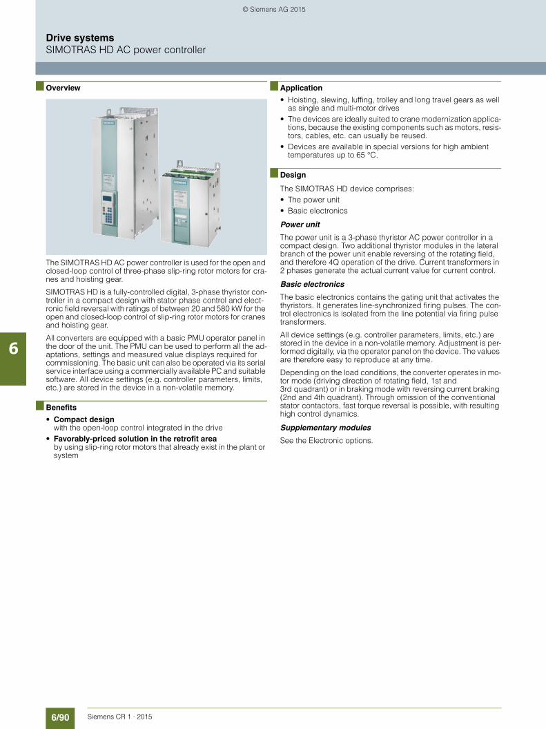
6/90 Siemens CR 1 · 2015
6
Drive systemsSIMOTRAS HD AC power controller
■ Overview
The SIMOTRAS HD AC power controller is used for the open and closed-loop control of three-phase slip-ring rotor motors for cra-nes and hoisting gear.
SIMOTRAS HD is a fully-controlled digital, 3-phase thyristor con-troller in a compact design with stator phase control and elect-ronic field reversal with ratings of between 20 and 580 kW for the open and closed-loop control of slip-ring rotor motors for cranes and hoisting gear.
All converters are equipped with a basic PMU operator panel in the door of the unit. The PMU can be used to perform all the ad-aptations, settings and measured value displays required for commissioning. The basic unit can also be operated via its serial service interface using a commercially available PC and suitable software. All device settings (e.g. controller parameters, limits, etc.) are stored in the device in a non-volatile memory.
■ Benefits
• Compact design with the open-loop control integrated in the drive
• Favorably-priced solution in the retrofit areaby using slip-ring rotor motors that already exist in the plant or system
■ Application
• Hoisting, slewing, luffing, trolley and long travel gears as well as single and multi-motor drives
• The devices are ideally suited to crane modernization applica-tions, because the existing components such as motors, resis-tors, cables, etc. can usually be reused.
• Devices are available in special versions for high ambient temperatures up to 65 °C.
■ Design
The SIMOTRAS HD device comprises:• The power unit• Basic electronics
Power unit
The power unit is a 3-phase thyristor AC power controller in a compact design. Two additional thyristor modules in the lateral branch of the power unit enable reversing of the rotating field, and therefore 4Q operation of the drive. Current transformers in 2 phases generate the actual current value for current control.
Basic electronics
The basic electronics contains the gating unit that activates the thyristors. It generates line-synchronized firing pulses. The con-trol electronics is isolated from the line potential via firing pulse transformers.
All device settings (e.g. controller parameters, limits, etc.) are stored in the device in a non-volatile memory. Adjustment is per-formed digitally, via the operator panel on the device. The values are therefore easy to reproduce at any time.
Depending on the load conditions, the converter operates in mo-tor mode (driving direction of rotating field, 1st and 3rd quadrant) or in braking mode with reversing current braking (2nd and 4th quadrant). Through omission of the conventional stator contactors, fast torque reversal is possible, with resulting high control dynamics.
Supplementary modules
See the Electronic options.
© Siemens AG 2015

6/91Siemens CR 1 · 2015
6
Drive systemsSIMOTRAS HD AC power controller
■ Function
Master switch signals
The incoming signals from the master switch, such as setpoint and control enable, are loaded.• A master switch with setpoint potentiometer can be connected
direct to the SIMOTRAS HD.• A 4-stage master switch requires the CUD2 terminal expan-
sion module for connection.
Ramp-function generator
The series-connected ramp-function generator with adjustable ramps forms the speed setpoint.
Speed controller
The speed controller with the subordinate current control circuit is connected down-circuit of the ramp-function generator and forms the actual control loop.
Start pulse
A start pulse is also generated so that the machine is activated in the hoisting direction of rotation immediately after power up. This prevents the load from dropping on start-up.
Sequencer
For switching through the rotor stages, a sequencer is installed that selects the planned stages speed-dependently and activa-tes reversing.
Standstill monitoring
The integral zero-speed monitoring supports guided, electrical braking of the drive. For replacing the cable, e.g. in hoists, jog mode with creep speed is provided.
Operating states
The operating states are indicated in the device on a 5-digit, 7-segment display as well as the LEDs of the basic PMU operator panel.
Operating modes
The threshold for switchover between closed-loop and open-loop controlled operation can be defined in accordance with the control characteristic and set on the parameters of the device.
Parallel connection
To increase the performance, up to 6 devices can be connected in parallel. The terminal expansion option (CUD2) is required in this case for every device and (n-1) patch cable. Current split-ting requires identical, separate parallel switching reactors for each SIMOTRAS device. The difference in reactor tolerances determines the current distribution. For operation without dera-ting (current reduction), a tolerance of 5 % or better is recom-mended. Only devices with the same current ratings are permit-ted to be connected in parallel.
© Siemens AG 2015

6/92 Siemens CR 1 · 2015
6
Drive systemsSIMOTRAS HD AC power controller
■ Integration
Crane technology
The drive-based (crane) control is integrated into the SIMOTRAS HD device. The SIMOTRAS HD device comprises:• Power unit• Electronics box with basic electronics
The drive-based (crane) control is designed to permit easy switchover between master switches with setpoint potentio-meters and 4-stage master switches: The control functions can be specified by terminals.
LatchRapidtraverse
Signal"No
Fault"
Actual currentvalue
acquisition
Equipment fan
Gating unit
Currentcontrol
Brake
Load
1) Signal from safety chain to brake control2) KTY84 connection or PTC thermistor to motor monitoring3) Analog tachometer or pulse encoder G = Analog tachometer IG = Pulse encoder4) Device fan connection5) Power unit connection
Currentlimiting
Speedcontroller
Ramp functiongenerator
Control word 1Bit 3
Acknowledgement
Signal"No fault"
Electronicspower supply
Masterswitch
Pre-limitswitch
Endswitch
Acknow-ledge
button
Ackn.
P24_S fromTerminal 34
OverloadHoisting gear
ElectricalStop
FeedbackBrake
Acknow-ledge
Full conduction
Reduction ofspeedcontroller start pulses
Pulse enable
Valid traversing command Start
pulseBrakingcontrol
Actualspeedvalue
Controllogic for
rotorcontactors
Mecha-nicalStop
Setpoint
G_CR01_EN_00163a
Monitoringof motortempera-
ture
Faulthandling
Setpoint lowering
Drive-based(crane)
controller
71
72
73
74
23
4
75
76
77
78
79
VE1
VE2
ES1
ES2
FK1
FK2
230 V~
G
n
100 %
&38
103104
86
85
87
88
89
90
91
92
93
94
U608
22 23
FKP654
FRP661
P665
U607
U605
U663
k01
34P24_S
AC 230 V
83
84
81
82 ST
MS
MS
1
5
M
P10N10
S1
S2
S3
S4
T1 T2 T3
U2 V2 W2
L1 L3L2
U1 V1 W1
PE
109
110ST
ST
=~
5U1 5W1 5N1 4U1 4V1 4W1
1)
2)
4)
1)
302826273129
90°0°
15 VM
IG3)
5)
wsgebrgr gn
N.C.
36
37
39
M3~
FR
SIMOTRAS HD
© Siemens AG 2015

6/93Siemens CR 1 · 2015
6
Drive systemsSIMOTRAS HD AC power controller
■ Configuration
Notes on configuration
Rated current of the device Irated
In crane operation, the motors are not operated continuously, but with variable load, at varying speeds, and with different ON du-rations. Under these conditions, it is sufficient when the rated current for the device Irated is greater than the motor rated cur-rent. In intermittent duty with appropriate pauses in operation, the devices can carry twice the rated device current of Irated gre-ater than the rated motor current for 20 s. In intermittent duty with appropriate pauses in operation, the devices can carry twice the rated device current of Irated for 20 s. This covers all the normal acceleration situations that occur with cranes. The SIMOTRAS HD devices can be operated continuously at the rated current for the device Irated; the limit temperature for the thyristors will, however, be reached. Acceleration is not permitted from this operating state since the thyristors could be overloaded.
Rotor contactors
To ensure a reliable ramp-up from the closed-loop control characteristic to rated speed, it is recommended that 4 rotor contactors are used. Activation of the rotor contactors through contactor relays.
Permissible ON duration
Under unusual operating conditions, such as traversing with full load at extremely low speed for a long time, motors, resistors and SIMOTRAS HD must be dimensioned appropriately. When phase angle control is used, a higher stator current flows to achieve the necessary torque due to the reduced magnetization. The motors may become thermally overloaded, because the thermal power losses rise with the quadrant of the current. The resistors are overloaded when the closed-loop control characte-ristic is traversed for an extended period.
Rotor resistances
Since the speed is influenced with additional rotor resistors, the rotor performance is largely converted into heat in the external resistor. This ensures that excessive heating of the motor is avo-ided when traversing at low speed over long periods.
Emergency or safety limit switch
Due to the lack of stator contactors, the motor can no longer be galvanically isolated from the AC power controller, e.g. when an operational limit switch is actuated. If the controller is then not able to block the thyristors due to a device fault, this could result in an impermissible operating state. It is therefore recommended that emergency or safety limit swit-ches are used. These respond when the operational limit switch is passed and act on a line contactor or the crane switch.
© Siemens AG 2015

6/94 Siemens CR 1 · 2015
6
Drive systemsSIMOTRAS HD AC power controller
■ Technical specifications
AC power controller in the basic version
Product designation SIMOTRAS HD AC power controller
Type 6SG7050-0EB60-0
6SG7052-0EB60-0
6SG7055-0EB60-0
6SG7060-0EB60-0
6SG7062-0EB60-0
6SG7065-0EB60-0
110 ... 500 V 3 AC, 60 ... 180 A
Rated supply voltage
Power unit
V 110 -10 % ... 500 + 10 % 3 AC
Rated frequency Hz 50/60
The devices automatically adjust to the frequency of the applied line voltage in a range from 45 ... 65 Hz.
Rated current A 60 78 98 112 142 180
Rated supply voltage
Electronic power supply
V 380 (-25 %) ... 460 (+15 %) 2 AC Irated = 1 A or 190 (25 %) ... 230 (+15 %) 1 AC Irated = 2 A(-35 % for 1 min.)
Phase fuse1)
3 units
A/V 3NE1820-0 80/690
3NE1021-0 100/690
3NE10220-0 125/690
3NE1024-0 160/690
3NE1224-0 160/690
3NE1225-0 200/690
Rated supply voltage
Fan
V – – 24 DC internal
Overload possibility2) 20 s duration: I = 2 × Iratedthen 70 s duration: I = Iratedthen 60 s duration: I = 0 A(cycle duration 150 s)
Power loss for rated current, approx.
W 272 306 386 439 500 630
Minimum load A 3 6 6 6 7 7
Ambient temperature during opera-tion at rated current
°C 0 ... 45self-ventilation
0 ... 40forced ventilation
Upper limit temperature with cur-rent derating
°C 55 50
Cooling air requirement m3/h – 100
Sound pressure level LpA (1 m) dB – 40
Storage and transport temperature °C -25 ... +70
Installation altitude above sea level m ≤ 1000 at rated current max. 3500 with reduced voltage and current
Environmental class DIN IEC 60721-3-3
3K3
Degree of protection DIN EN 60529
IP00 IP00 IP00 IP00 IP00 IP00
D400 device type 60 Mre 78 Mre 98 Mre 112 Mre 142 Mre 180 Mre
Dimensions See dimensional drawings
Weight, approx. kg 16 16 16 16 17 17
1) The fuses listed are not included with the device. The fuses listed are recommended fuses that must be ordered separately.
2) It is permissible to operate the device without interruption with the rated connection current Irated. This will cause the thyristors to reach their limit temperature. It is not possible to accelerate, i.e. increase the current from this operating state.
© Siemens AG 2015

6/95Siemens CR 1 · 2015
6
■ Technical specifications (continued)
Drive systemsSIMOTRAS HD AC power controller
Product designation SIMOTRAS HD AC power controller
Type 6SG7070-0EB60-0
6SG7072-0EB60-0
6SG7076-0EB60-0
6SG7080-0EB60-0
6SG7082-0EB60-0
6SG7085-0EB60-0
110 ... 500 V 3 AC, 225 ... 900 A
Rated supply voltage
Power unit
V 110 -10 % ... 500 + 10 % 3 AC
Rated frequency Hz 50/60
The devices automatically adjust to the frequency of the applied line voltage in a range from 45 ... 65 Hz.
Rated current A 225 285 360 525 680 900
Rated supply voltage
Electronic power supply
V 380 (-25 %) ... 460 (+15 %) 2 AC Irated = 1 A or 190 (-25 %) ... 230 (+15 %) 1 AC Irated = 2 A(-35 % for 1 min.)
Phase fuse1)
3 units
A/V 3NE1227-0250/690
3NE1331-0350/690
3NE1332-0400/690
3NE1435-0560/690
3NE3340-8900/690
6RY1702-0BA012) '
1250/660
Rated supply voltage
Fan
V 400 (± 15 %) 3 AC 50 Hz460 (± 10 %) 3 AC 60 Hz
400 (± 10 %) 3 AC 50 Hz 460 (± 10 %) 3 AC 60 Hz
Rated current
Fan
A 0.24 1.1
Overload possibility3) 20 s duration: I = 2 × Iratedthen 70 s duration: I = Iratedthen 60 s duration: I = 0 A(cycle duration 150 s)
Power loss for rated current, approx.
W 839 1020 1300 1827 2890 3550
Minimum load A 10 10 10 15 15 15
Ambient temperature during ope-ration at rated current
°C 0 ... 40forced ventilation
Upper limit temperature with cur-rent derating
°C 50
Cooling air requirement m3/h 570 1400 2400
Sound pressure level LpA (1 m) dB 73 88
Storage and transport temperature °C -25 ... +70
Installation altitude above sea level m ≤ 1000 at rated current max. 3500 with reduced voltage and current
Environmental class DIN IEC 60721-3-3
3K3
Degree of protection DIN EN 60529
IP00 IP00 IP00 IP00 IP00 IP00
D400 device type 225 Mre 285 Mre 360 Mre 525 Mre 680 Mre 900 Mre
Dimensions See dimensional drawings
Weight, approx. kg 30 30 30 45 85 137
1) The fuses listed are not included with the device. The fuses listed are recommended fuses that must be ordered separately.
2) Fuses included with device. No semiconductor fuses are necessary.3) It is permissible to operate the device without interruption with the rated
connection current Irated. This will cause the thyristors to reach their limit temperature. It is not possible to accelerate, i.e. increase the current from this operating state.
© Siemens AG 2015

6/96 Siemens CR 1 · 2015
6
■ Technical specifications (continued)
Drive systemsSIMOTRAS HD AC power controller
AC power controller in the special version
Product designation SIMOTRAS HD AC power controller
Type 6SG7050-0EB60-0-ZH78
6SG7052-0EB60-0-ZH78
6SG7055-0EB60-0-ZH78
6SG7060-0EB60-0-ZH78
6SG7062-0EB60-0-ZH78
6SG7065-0EB60-0-ZH78
110 ... 500 V 3 AC, 42 ... 125 A, ambient temperature 65 °C (option H78)
Rated supply voltage
Power unit
V 110 -10 % ... 500 + 10 % 3 AC
Rated frequency Hz 50/60
The devices automatically adjust to the frequency of the applied line voltage in a range from 45 ... 65 Hz.
Rated current A 42 55 70 80 100 125
Rated supply voltage
Electronic power supply
V 380 (-25 %) ... 460 (+15 %) 2 AC Irated = 1 A or 190 (-25 %) ... 230 (+15 %) 1 AC Irated = 2 A(-35 % for 1 min.)
Phase fuse1)
3 units
A/V 3NE1820-0 80/690
3NE1021-0 100/690
3NE10220-0 125/690
3NE1024-0 160/690
3NE1224-0 160/690
3NE1225-0 200/690
Rated supply voltage
Fan
V – 24 DC internal
Overload possibility2) 20 s duration: I = 2 × Iratedthen 70 s duration: I = Iratedthen 60 s duration: I = 0 A(cycle duration 150 s)
Power loss for rated current, approx.
W 205 230 288 322 365 445
Minimum load A 3 6 6 6 7 7
Ambient temperature during ope-ration at rated current
°C 0 ... 65
Cooling air requirement m3/h – 100
Sound pressure level LpA (1 m) dB – 40
Storage and transport temperature °C -25 ... +70
Installation altitude above sea level m ≤ 1000 at rated current max. 3500 with reduced voltage and current
Environmental class DIN IEC 60721-3-3
3K3
Degree of protection DIN EN 60529
IP00 IP00 IP00 IP00 IP00 IP00
D400 device type 60 Mre 78 Mre 98 Mre 112 Mre 142 Mre 180 Mre
Dimensions See dimensional drawings
Weight, approx. kg 16 16 16 16 17 17
1) The fuses listed are not included with the device. The fuses listed are recommended fuses that must be ordered separately.
2) It is permissible to operate the device without interruption with the rated connection current Irated. This will cause the thyristors to reach their limit temperature. It is not possible to accelerate, i.e. increase the current from this operating state.
© Siemens AG 2015

6/97Siemens CR 1 · 2015
6
■ Technical specifications (continued)
Drive systemsSIMOTRAS HD AC power controller
Option H78:
Operation at an ambient temperature higher than +65 °C is not possible. The rated current, reduced compared to the standard version, must be maintained across the entire temperature range of 0 ... 65 °C.
Product designation SIMOTRAS HD AC power controller
Type 6SG7070-0EB60-0-ZH78
6SG7072-0EB60-0-ZH78
6SG7076-0EB60-0-ZH78
6SG7080-0EB60-0-ZH78
6SG7082-0EB60-0-ZH78
6SG7085-0EB60-0-ZH78
110 ... 500 V 3 AC, 150 ... 700 A, ambient temperature 65 °C (option H78)
Rated supply voltage
Power unit
V 110 -10 % ... 500 + 10 % 3 AC
Rated frequency Hz 50/60
The devices automatically adjust to the frequency of the applied line voltage in a range from 45 ... 65 Hz.
Rated current A 150 200 250 365 475 700
Rated supply voltage
Electronic power supply
V 380 (-25 %) ... 460 (+15 %) 2 AC Irated = 1 A or 190 (-25 %) ... 230 (+15 %) 1 AC Irated = 2 A(-35 % for 1 min.)
Phase fuse1)
3 units
A/V 3NE1227-0 250/690
3NE1331-0 350/690
3NE1332-0 400/690
3NE1435-0 560/690
3NE3340-8 900/690
6RY1702-0BA012)
1250/660
Rated supply voltage
Fan
V 400 (± 15 %) 3 AC 50 Hz460 (± 10 %) 3 AC 60 Hz
400 (± 10 %) 3 AC 50 Hz460 (± 10 %) 3 AC 60 Hz
Rated current
Fan
A 0.24 1.1
Overload possibility3) 20 s duration: I = 2 × Iratedthen 70 s duration: I = Iratedthen 60 s duration: I = 0 A(cycle duration 150 s)
Power loss for rated current, approx.
W 595 731 895 1280 2146 2865
Minimum load A 10 10 10 15 15 15
Ambient temperature during ope-ration at rated current
°C 0 ... 65
Cooling air requirement m3/h 570 1400 2400
Sound pressure level LpA (1 m) dB 73 88
Storage and transport temperature °C -25 ... +70
Installation altitude above sea level m ≤ 1000 at rated current max. 3500 with reduced voltage and current
Environmental class DIN IEC 60721-3-3
3K3
Degree of protection DIN EN 60529
IP00 IP00 IP00 IP00 IP00 IP00
D400 device type 225 Mre 285 Mre 360 Mre 525 Mre 680 Mre 900 Mre
Dimensions See dimensional drawings
Weight, approx. kg 30 30 30 45 85 137
1) The fuses listed are not included with the device. The fuses listed are recommended fuses that must be ordered separately.
2) Fuses included with device. No semiconductor fuses are necessary.3) It is permissible to operate the device without interruption with the
rated connection current Irated. This will cause the thyristors to reach their limit temperature. It is not possible to accelerate, i.e. increase the current from this operating state.
© Siemens AG 2015
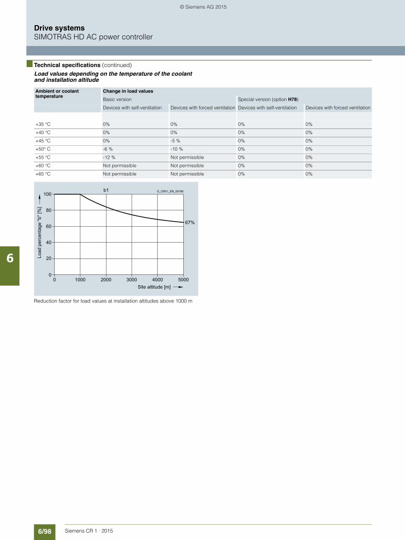
6/98 Siemens CR 1 · 2015
6
■ Technical specifications (continued)
Drive systemsSIMOTRAS HD AC power controller
Load values depending on the temperature of the coolant and installation altitude
Reduction factor for load values at installation altitudes above 1000 m
Ambient or coolant temperature
Change in load values
Basic version Special version (option H78)
Devices with self-ventilation Devices with forced ventilation Devices with self-ventilation Devices with forced ventilation
+35 °C 0% 0% 0% 0%
+40 °C 0% 0% 0% 0%
+45 °C 0% -5 % 0% 0%
+50° C -6 % -10 % 0% 0%
+55 °C -12 % Not permissible 0% 0%
+60 °C Not permissible Not permissible 0% 0%
+65 °C Not permissible Not permissible 0% 0%
200010000 3000 4000 5000
67%
100
80
60
40
20
0
b1
Site altitude [m]
G_CR01_EN_00166
Load
per
cent
age
"b" [
%]
© Siemens AG 2015

6/99Siemens CR 1 · 2015
6
Drive systemsSIMOTRAS HD AC power controller
■ Selection and ordering data
■ Options
The SIMOTRAS HD converters can be ordered with the following options:
Operating Instructions in German are supplied with everydevice.
Data position of Article No. 1 2 3 4 5 6 7 8 9 10 11 12 13 -Z Order code
SIMOTRAS HD
Basic version up to +40 °C or +45 °C
6 S G ■ ■ ■ ■ - ■ ■ ■ ■ ■ - 0
SIMOTRAS HD
Special version up to +65 °C
6 S G ■ ■ ■ ■ - ■ ■ ■ ■ ■ - 0 -Z H78
Device version
DC and AC power controllers for power control 7 0
Rated current
Basic version Special version(option H78)
60 A 42 A 5 0
78 A 55 A 5 2
98 A 70 A 5 5
112 A 80 A 6 0
142 A 100 A 6 2
180 A 125 A 6 5
225 A 150 A 7 0
285 A 200 A 7 2
360 A 250 A 7 6
525 A 365 A 8 0
680 A 475 A 8 2
900 A 700 A 8 5
Version
Thyristor 0
Rated voltage
500 V E
Current transformer
With current transformer B
Converter circuit
4-quadrant device 6 0
Description Article No. Order code
Operation of the SIMOTRAS HD devices at +65 °C ambient temperature
H78
SIMOTRAS HD Operating Instructions
In printed form
Languages: English
6SG7000-0BA76 D76
SIMOTRAS HD Operating Instructions and DriveMonitor commissioning tool
On CD-ROM
Languages: English, German
6SG7000-0CD00 D64
© Siemens AG 2015

6/100 Siemens CR 1 · 2015
6
Drive systemsSIMOTRAS HD AC power controller
■ Characteristic curves
The speed changes steplessly in the control range when the master switch is operated. The crane driver only detects the end of the control range through latching of the master switch. Fur-thermore, the final stage is reached sub-synchronously or super-synchronously, depending on the load, by traversing the charac-
teristics that are determined by the resistor increments. Current control is always operating to ensure that the set maximum torques are not exceeded. It goes without saying that the circuits are protected against reversal.
Control characteristics for hoists
Up to 4 rotor resistor switching stages can be provided. If less than 4 stages are implemented, the top stages (S3/S4) remain unused.
If the upper stages S3/S4 are not used, the over-synchronized speed increases in accordance with the parameterized charac-teristic on lowering. This must be taken into account when selec-ting overspeed protection. For this reason, a speed correspon-ding to the characteristic can also only be achieved during lifting.
100
80
60
40
20
-20
-60
-80
-120
%
%
-140 -100 -60 -20
20 60 100 140 180
%
%
*
*
*
S3
S2
S1
S4
S3
S2
S1
S4
-40
K
-M
K
-n
+M
+n
Driving lifting
Braking lowering
Braking lifting
Full-load curve lifting
Full-load curve lowering
Driving lowering
G_C
R01
_EN
_001
61
SIMOTRAS HD control range
K Characteristics for reversing mode (counter-current braking), i.e. Delay lowering with pull-through loads or Delay lifting when active reversing mode is required S2, S3, S4 Characteristics for controlled mode
* Use of current limiting (e.g. Imax = 2 x Irated)
© Siemens AG 2015

6/101Siemens CR 1 · 2015
6
■ Characteristic curves (continued)
Drive systemsSIMOTRAS HD AC power controller
Control characteristics for gantries
Up to 4 rotor resistor switching stages can be provided. If less than 4 stages are implemented, the top stages (S3/S4) remain unused.
100
80
60
40
20
-20
-40
-60
-80
-120
%
%
-140 -100 -60 -20
20 60 100 140 180
%
%
*
*
*
S3
S2
S1
S4
S3
S2
S1
CW rotation, driving
CCW rotation, braking
CW rotation, braking
K
-M
K
-nCCW rotation, driving
+M
+n
G_C
R01
_EN
_001
62
SIMOTRAS HD control range
K Characteristics for reversing mode (counter-current braking)
S3 Characteristics for controlled mode
* Use of current limiting (e.g. Imax = 2 x Irated)
© Siemens AG 2015

6/102 Siemens CR 1 · 2015
6
Drive systemsSIMOTRAS HD AC power controller
■ Dimensional drawings
D400/60-180 Mre device type
D400/225-360 Mre device type
Side view Front viewElectronics box
G_C
R01
_EN
_001
57283 with door
100
1
00
25 37 48 37 48 15
V1
V2V3
V5V6
T2 T3
XT
9
270 150
350
1)
129
385
366
265 230 17.5
38.5
12.5
83.5 1) L3/
W2 T3/W2
L2/V1
T2/V2
L1/U1
T1/U2
X2_1X2_2X2_3X2_4 5W1X1
G_C
R01
_EN
_001
56
318 with door
Side view Front viewElectronics box
10
19
10
V2V3V1
T2 T3
100
306
585
1
00
35 120
136 160 174 139
98 135
602
230 268
625
47.5 1)
1)
39 47.5
47.5 47.5
V5V6
X2_1X2_2X2_3X2_4 5W1X1
U1L1
V2T2
V1L2
W2T3
W1L3
U2T1
1) Minimum clearance for air circulation. An adequate flow of cooling air must be provided.
© Siemens AG 2015

6/103Siemens CR 1 · 2015
6
■ Dimensional drawings (continued)
Drive systemsSIMOTRAS HD AC power controller
D400/525 Mre device type
D400/680 Mre device type
108
30
30 30
30
U1/L1
U2/T1
V1/L2 W1/L3
V5V6
V2V3V1
T3T2
12
360 150
660
40 275 142 50
700
6
77
119 205
111
331)
100
1)
1
00
268 230 19
W2/T3V2/T2
for M10
Eyebolt Ø 20
G_C
R01
_EN
_001
58
For M8
Side view Front view1)
1
00
U1/L1
V1/L2
10
25
30
3030 1
00 1)
7
40
50 153
406 320
780
7
57
56 188
320
15
8
W1/L3
360
V5V6
V2V3V1
T1T2
150
U2/T1
V2/T2
W2/T3
17.5
43 Eyebolt Ø 20
G_C
R01
_EN
_001
59
For M10
Side view Front view
1) Minimum clearance for air circulation. An adequate flow of cooling air must be provided.
© Siemens AG 2015
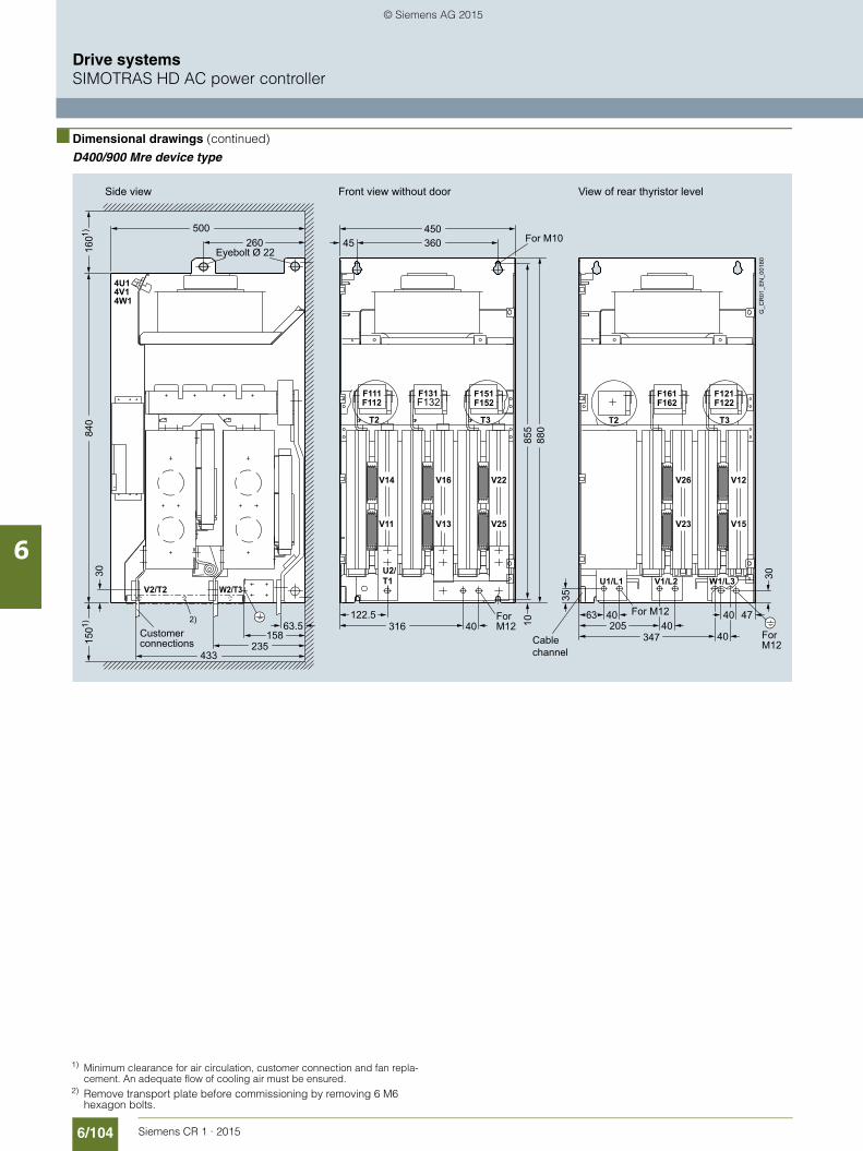
6/104 Siemens CR 1 · 2015
6
■ Dimensional drawings (continued)
Drive systemsSIMOTRAS HD AC power controller
D400/900 Mre device type
For M10Eyebolt Ø 22
ForM12Cable
channel
ForM12
Customerconnections
For M12
G_C
R01
_EN
_001
60
Side view Front view without door View of rear thyristor level
150
1)
47
10
U1/L1 V1/L2 W1/L3W2/T3V2/T2
347 40
40 205
63 40
35
316 40
450 360
855
8
80
433 235
260 500
30
45
4U14V14W1
V26 V12
V23 V15
V14 V16 V22
V11 V13 V25
T3
F162F121F122
T2 T3
F111F112
F131F132
F151F152
840
1
60 1)
2)
U2/T1
T2
30
40 158
122.5 63.5
F161
1) Minimum clearance for air circulation, customer connection and fan repla-cement. An adequate flow of cooling air must be ensured.
2) Remove transport plate before commissioning by removing 6 M6 hexagon bolts.
© Siemens AG 2015
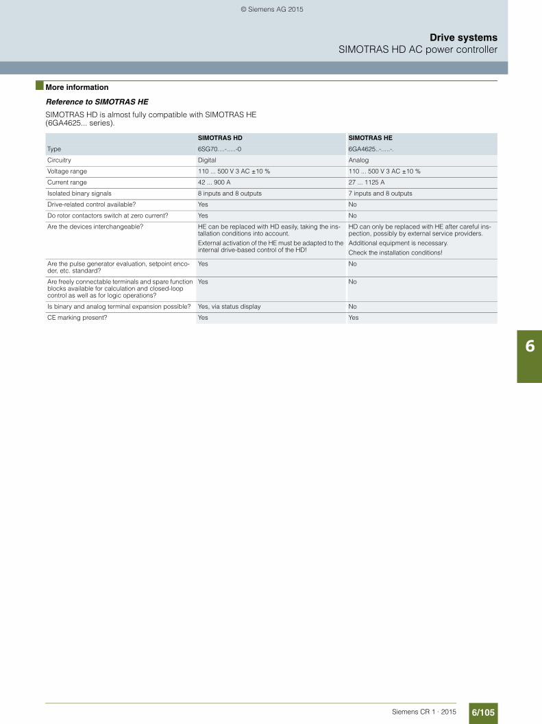
6/105Siemens CR 1 · 2015
6
Drive systemsSIMOTRAS HD AC power controller
■ More information
Reference to SIMOTRAS HE
SIMOTRAS HD is almost fully compatible with SIMOTRAS HE (6GA4625... series).
SIMOTRAS HD SIMOTRAS HE
Type 6SG70....-.....-0 6GA4625..-.....-.
Circuitry Digital Analog
Voltage range 110 ... 500 V 3 AC ±10 % 110 ... 500 V 3 AC ±10 %
Current range 42 ... 900 A 27 ... 1125 A
Isolated binary signals 8 inputs and 8 outputs 7 inputs and 8 outputs
Drive-related control available? Yes No
Do rotor contactors switch at zero current? Yes No
Are the devices interchangeable? HE can be replaced with HD easily, taking the ins-tallation conditions into account.
External activation of the HE must be adapted to the internal drive-based control of the HD!
HD can only be replaced with HE after careful ins-pection, possibly by external service providers.
Additional equipment is necessary.
Check the installation conditions!
Are the pulse generator evaluation, setpoint enco-der, etc. standard?
Yes No
Are freely connectable terminals and spare function blocks available for calculation and closed-loop control as well as for logic operations?
Yes No
Is binary and analog terminal expansion possible? Yes, via status display No
CE marking present? Yes Yes
© Siemens AG 2015

6/106 Siemens CR 1 · 2015
6
Drive systemsSIMOTRAS HD AC power controller
Electronic options
■ Overview
Electronics options are available for SIMOTRAS for expanding the interfaces available as standard.
The CUD2 terminal expansion module expands the SIMOTRAS HD with the necessary inputs/outputs for connecting a 4-stage master switch. A master switch with a setpoint poten-tiometer can be connected direct to the SIMOTRAS HD without a CUD2 terminal expansion module.
The CUD2 terminal expansion module is ordered separately and mounted on-site in the SIMOTRAS HD.
■ Selection and ordering data
■ Accessories
The following accessories are also available for SIMOTRAS HD:
Description Article No.
Terminal expansion module CUD2 6RX1700-0AK00
Description Article No.
Connecting cable between DriveMonitor and PC PMU (RS232)
Length: 3 m
9AK1012-1AA00
SIMOTRAS HD Operating Instructions
In printed form:• German• English
6SG7000-0BA00
6SG7000-0BA76
SIMOTRAS HD Operating Instructions and DriveMonitor commissioning tool
On CD-ROM
Languages: English, German
6SG7000-0CD00
© Siemens AG 2015

Siemens CR 1 · 2015
77/2 Overview7/2 Type overview and rating plate
7/4 General technical specifications7/4 Overview7/4 Application7/4 Configuration7/9 Technical specifications
7/12 SIMOTICS M – Servo motors7/12 1PH8 for SINAMICS S120 for cranes7/12 Overview7/12 Benefits7/12 Technical specifications7/14 1PH8 for SINAMICS S120 for cranes –
Degree of protection IP237/14 Selection and ordering data7/18 1PH8 for SINAMICS S120 for cranes –
Degree of protection IP557/18 Selection and ordering data7/22 Article No. supplements7/23 Options7/25 Dimensional drawings
7/26 SIMOTICS SD – Severe Duty motors7/26 1LP4, 1LP6 with mounted spring-set brake7/26 Overview7/27 Technical specifications7/29 KFB spring-set brake
for SIMOTICS SD 1LP4, 1LP67/29 Design7/31 Configuration7/33 Technical specification7/34 1LP4, 1LP6 SH 132S - 280M7/34 Selection and ordering data7/54 Options7/56 Dimensional drawings7/59 1LG4, 1LG6 SH 315 L with external fan7/60 Selection and ordering data7/72 Options7/74 Dimensional drawings
SIMOTICS motors for cranes
© Siemens AG 2015

7/2 Siemens CR 1 · 2015
7
SIMOTICS motors for cranesOverview
Type overview and rating data
■ Overview
Application Motor type Characteristics Degree of protection
Cooling method Shaft height
SIMOTICS M-1PH8 Asynchronous servo motor without housing
IP23
IP55
Forced ventilation
Forced ventilation
SH 355
SH 355
Page 7/12
SIMOTICS M-1PH8 Asynchronous servo motor without housing
IP55
IP23Forced ventilation
Forced ventilation
SH 80 – 280
SH 180 – 280
Catalog PM 21
SIMOTICS SD 1LE1 Asynchronous standard motor
IP55 Self-ventilated SH 100 – 315 Catalog D 81.1
SIMOTICS SD 1LG4, 1LG6 Asynchronous standard motor
IP55 Self-ventilated SH 100 – 280 Catalog D 81.1
SIMOTICS SD 1LP4, 1LP6 Asynchronous standard motor
IP55 Natural cooling SH 132 S – 280 M Page 7/26
SIMOTICS SD 1LG4, 1LG6 Asynchronous standard motor
IP55 Surface cooling with forced ventilation
SH 315 L Page 7/59
© Siemens AG 2015

7/3Siemens CR 1 · 2015
7
■ Overview (continued)
SIMOTICS motors for cranesOverview
Type overview and rating data
Output range in kW Torque range in Nm Drive system
1 10 100 1 000 10 100 1 000 10 000
SINAMICS S120
SINAMICS S120
SINAMICS S120
SINAMICS S120
SINAMICS S120
SINAMICS S120
S1
370 1340
S1
230 730
S1
4740 12415
S1
2688 6844
S1
2.8 385
S1
24.5 630
S1
13 2480
S1
317 3600
S1
1.75 200
S1
15 1546
S1
1.75 104
S1
15 579
S3-25 %
3 132
S3-25 %
30 873
113 372
S3-60 %
1124 2628
S3-60 %
© Siemens AG 2015

7/4 Siemens CR 1 · 2015
7
SIMOTICS motors for cranes
General technical specifications
■ Overview
Siemens has for many years been one of the leading manufac-turers of crane motors. This type overview covers the current range of three-phase motors for use in cranes. The technical specifications for hoisting motors 1PH8 of shaft height 355 (85 dB(A)), for gantry motors 1LP4, 1LP6 of shaft height 132-280 with fitted brake and for the hoisting motors 1LG4, 1LG6 of shaft height 315 with external fan you can find in this Catalog.
The technical specifications for the hoisting motors 1PH8 of shaft height 80-280 can be found in Catalog PM21, Chapter 5 SIMOTICS main motors. For the technical specifications for hoi-sting- and gantry motors 1LE1 of shaft height 100-315 and 1LG4, 1LG6 of shaft height 100-280 see Catalog D 81.1.
In addition to these motors, for high outputs in hoisting gear, SIMOTICS FD motors (1LM1/1LQ1/1LL1/1LP1, Catalog D 81.8) can be used as hoist motors in converter-fed drives.
The range of crane motors is aimed at crane manufacturers, sys-tem integrators, and crane operators. To make it easier to select motors, they are listed by speed and output (continuous and in-termittent duty). The tables indicate the rated motor torques and the maximum permissible torques.
The asynchronous motors with the DURIGNIT 2000 winding insulation are suitable for use on the SINAMICS S120 drive sys-tem. Since the hoist motors in particular operate in a large field weakening range during converter operation, you must check – alongside the usual design criteria such as thermal load (rms torque) and maximum acceleration torque – whether the motor can still generate the required maximum torque in the field wea-kening range. A torque-speed diagram can be created to check this.
The requirements of the motors vary depending on the applica-tion conditions: • Gantry cranes that are used in production halls are not usually
directly subjected to climatic influences. The motors do not necessarily need high degrees of protection or special paint.
• Cranes located in seaports are often exposed to harsh wea-ther, which means that special measures must be taken to pro-tect the motors against corrosion as well as the ingress of dust and water.
• Cranes in steel works are often subject to very high ambient temperatures. The electrical and mechanical design (e.g. special bearings) must take this into account.
■ Application
Siemens crane motors are particularly suitable for crane opera-tions under difficult conditions. These robust motors • offer a high degree of protection and are particularly suitable
for harsh operating conditions• offer torque reserves that can handle high impulse loads• are specially optimized for high-inertia drives with high torque
Both SIMOTICS SD and SIMOTICS M motors are used in crane applications.
SIMOTICS M are main motors which are used in crane applica-tions primarily as hoist motors. With a power spectrum ranging from 2.8 kW to 1340 kW, they cover virtually every application. The compact asynchronous servo motors/main spindle motors are perfectly adapted to the SINAMICS S120 drive system.
The compact SIMOTICS SD asynchronous standard motors with cast-iron housing are particularly rugged and are, therefore, the first choice in crane applications.
■ Configuration
Motor dimensioning
When motors for crane drives are dimensioned (high-inertia drives), two criteria must be taken into account:• The required maximum torque (starting torque)• The rated output (thermal motor capacity)
When you check the torque, you check whether the motor can generate the required maximum torque (e.g. for acceleration). The maximum permissible torque is greater than the rated torque and is often specified as a multiple of the rated torque. An adequate safety margin from the stalling torque must be maintai-ned.
When the output is dimensioned, the rated motor output is adjus-ted in accordance with the effective power requirements of the drive. The rated motor output depends on the motor temperature which, in turn, is influenced by the operating mode and the ther-mal behavior of the motor. The rating data of a motor differs for the various operating modes in accordance with EN 60034-1. The data is usually specified for one or more of the following ope-rating modes:• Continuous duty S1 (also corresponds to intermittent duty
S3-100 %)• Short-time duty S2• Intermittent duty S3
Intermittent duties S4 and S5 vary to such an extent that accu-rate data can only be provided when certain additional condi-tions have been clearly defined.
The operating modes are defined in accordance with EN 60034-1.
Symbols used in formulae:
P Load/specified motor output
PV Power loss of the motor
ϑe Final temperature, steady-state temperature
ϑmax Max. winding temperature in respective operating mode
ϑmean Mean winding temperature
te Operating time
tP Idle time
tS Duty cycle duration
TL Thermal time constant of the motor (running)
TSt Thermal time constant of the motor (stationary)
© Siemens AG 2015

7/5Siemens CR 1 · 2015
7
■ Configuration (continued)
SIMOTICS motors for cranes
General technical specifications
Continuous duty (S1)
Definition
Operation with a constant load state, the duration of which is suf-ficient to attain thermal equilibrium.
Explanation
The operating time te of the motor must be greater than 3 × TL to ensure that thermal equilibrium is attained. The rated motor out-put for continuous duty must be designed such that the final temperature ϑe matches the permissible winding temperature. Start-up is deliberately discounted under the assumption that a single high-inertia start will not achieve the final temperature. The length of the subsequent idle time is insignificant. Caution is advised, however, when high-inertia starting is carried out on a warm machine or when a machine is started up several times in succession. Certain restrictions may apply or advice from a third party should be sought.
Short-time duty (S2)
Definition
Operation with a constant load state that, however, does not last long enough to attain thermal equilibrium, followed by idle time that lasts until the machine temperature differs from the coolant temperature by no more than 2 K.
Explanation
The operating time te must be less than 3 × TL to ensure that the theoretical final temperature is not reached. The rated motor out-put and the operating time are harmonized in such a way that the maximum winding temperature ϑmax does not exceed the permissible values. Here, too, start-up is deliberately discounted because it is assumed that the machine starts up cold and the start-up procedure is short with respect to the operating time te.
The rated motor output for short-time duty can be higher than for continuous duty, although the permissible operating time must also be specified. The shorter the operating time, the higher the rated output of the machine. Operating times of 10, 30, 60, and 90 minutes are recommended.
The subsequent idle time must be sufficiently long to ensure that the machine can cool back down to the ambient temperature (i.e. tP is greater than or equal to 3 × TSt) because otherwise the maximum temperature will be exceeded the next time a similar duty cycle is carried out.
P
t
PV
t
t
TL
e max.=
≥te 3 T. L
G_CR01_EN_00012
G_CR01_EN_00013
tPe
PV
P
t
t
t
t
max.
e
<te 3 T. L≥tP 3 T. St
© Siemens AG 2015

7/6 Siemens CR 1 · 2015
7
■ Configuration (continued)
SIMOTICS motors for cranes
General technical specifications
Intermittent duty without the effect of the start-up process (S3)
Definition
Operation that involves a sequence of similar duty cycles, each with a constant-load period and idle time, whereby the starting current does not have a noticeable effect on the temperature rise (the duty cycle duration is generally short enough to ensure that thermal equilibrium is not attained).
Explanation
The operating time te must be less than 3 × TL to ensure that the theoretical final temperature ϑe is not reached. The subsequent idle time tp, however, is also less than 3 × TSt, which means that the ambient temperature is no longer reached. A mean steady-state value ϑmean develops around which the tempera-ture varies, but is below the theoretical final temperature ϑe.
The rated motor output during intermittent duty is greater than during continuous duty. The time constants TL and TSt may be different. This influences the rated output during intermittent duty and is taken into account in the S3 motor tables.
To determine the most suitable motor, therefore, a knowledge of the operating and idle times is required in addition to the requi-red output during the operating time. They are specified by the duty cycle duration (total time) and the relative ON duration in % of the cycle duration. If no data has been provided for the duty cycle duration, 10 minutes apply in accordance with DIN EN 60034-1. The S3 motor tables are based on this. Values of 15, 25, 40, and 60 % are recommended for the cyclic duration factor.
Effect of varying duty cycle durations
The S3 rated output is designed in such a way that the tempera-ture peaks ϑmax match the permissible values with a 10 minute duty cycle duration (see "a" in diagram below). Shorter duty cycle durations are not critical because lower temperature peaks occur at the same mean winding temperature ϑmean (see "b" in diagram below). Since longer duty cycle durations result in higher temperature peaks (see "c" in diagram below) which, in turn, reduce the service life of the insulation, advice from a third party should be sought in this case.
In S3 duty, the start-up processes are not discounted; the rele-vant standard assumes that they do not have any significant in-fluence on the temperature rise. Any number of duty cycles can be carried out per hour provided that this standard is fulfilled.
P
t
PV
t
t
e
max.
<te 3 T. L<tP 3 T. St
te tP
tS
G_CR01_EN_00014
mean
G_CR01_EN_00015
mean
minutes
max.
ta b c
10
max.a max.b
max.c
tSa tSb
tSatSb
tSc
tSc<<
<<
= 10 min
max.b max.a max.c
© Siemens AG 2015

7/7Siemens CR 1 · 2015
7
■ Configuration (continued)
SIMOTICS motors for cranes
General technical specifications
Intermittent duty with effect of the start-up process (S4) Intermittent duty with effect of the start-up process and electrical braking (S5)
Definition
Operation that involves a sequence of similar duty cycles, each with a noticeable start-up time, a constant-load period, a period of rapid electrical braking (with S5), and idle time.
Intermittent duty S4
Intermittent duty S5
Explanation
These operating modes closely resemble S3 duty, except that the temperature rise caused by start-up and, in some cases, electrical braking are also included. This additional power loss depends on the acceleration torque and the time in which this occurs; in other words, it depends on the linear and rotating masses to be accelerated (kinetic energy). The masses that are moved, therefore, must be known. These are based on the mo-ment of inertia referred to the motor shaft. How often and over what period of time the masses are subject to acceleration and braking procedures must also be known.
The more duty cycles performed by the crane drives every hour (e.g. short traveling distances or low hoisting heights), the grea-ter the importance of the acceleration work for motor dimensio-ning purposes.
To accurately dimension a motor for duty cycles S4 and S5, therefore, the following information is required in addition to the steady-state output:• Cyclic duration factor (CDF)• External moment of inertia• Acceleration or acceleration torque• Accelerating time• Number of working cycles per hour
General performance specifications for motors in S4/S5 duty are not possible because they always vary depending on the speci-fic conditions under which the driven machine is operating (ex-ternal moment of inertia) and the operating mode (working cyc-les, ON duration). Crane drives do not have a constant load across several working cycles but instead have a collective load.
G_CR01_EN_00016
mean
max.
t
t
t
e
P
PV
tSte tP tA
G_CR01_EN_00017
mean
max.
t
t
t
e
P
PV
tSte tP
© Siemens AG 2015

7/8 Siemens CR 1 · 2015
7
■ Configuration (continued)
SIMOTICS motors for cranes
General technical specifications
Calculating the rms value, ON duration
Actual duty can also be converted to a thermally equivalent S3 mode by means of "rms value calculation", which means that the S3 motor tables can be used again.
A torque diagram (duty cycle diagram) must be available when the calculation is performed (see diagrams below).
The value (assumed to be constant throughout the operating time) that would generate the same temperature rise as the ac-tual torque is defined as the rms torque. The ON duration is the sum of operating times with respect to the total duty cycle dura-tion.
If the individual traveling duty cycles are not the same (e.g. due to different loads or distances), all the different traveling cycles must be included in the rms value and ON duration calculation until they repeat themselves.
Differences in thermal behavior when the motor is running and when it is at a standstill are already taken into account with res-pect to the ON durations in the S3 tables. For this reason, Mrms must be calculated with respect to the operating time te and not to the duty cycle duration tS.
To ensure that the rms value can be defined with sufficient accu-racy, however, the operating phases during which the motor is not cooled as efficiently must be taken into account (e.g. during correction runs at low speeds and with naturally cooled motors).
Effects such as these can only be taken into account by the mo-tor manufacturer.
The operating conditions for hoist and traversing gears also vary enormously:• The external moment of inertia with respect to the motor mo-
ment of inertia is usually greater in traversing gears than in hoist gears; in other words, the acceleration and braking work are more relevant for traversing gears than for hoists even when the number of duty cycles performed and the ON duration are the same.
• The steady-state torque (load torque) with respect to the rated motor torque is usually greater in hoists than in traversing ge-ars (traveling resistance).
• The torque diagram for traversing gears does not take the di-rection of travel into account (without wind forces). The effect of the payload is minimal with high traversing gear weights; i.e. with handling cranes, it is repeated after each travel move-ment (after the second travel movement at the latest).
• The torque diagram for hoists is largely dependent on the load. The motor torques when the same load is hoisted and lo-wered are different (efficiency) and, in the case of handling cranes, a traveling duty cycle with a load is usually followed by a traveling duty cycle with empty load tackle (collective loa-ding; see also FEM, Section I, Calculation Principles for Cra-nes); i.e. the cycle required for calculating the rms value is re-peated after the fourth travel movement at the earliest.
Torque diagram
Typical torque diagram for a gantry across one conveying cycle
Typical torque diagram for hoist across one conveying cycle
ED ON timeMrms rms torqueM1, M2, M3 Torques in travel diagramt1, t2, t3 Operating times of torques M1, M2, M3tP Idle timete Operating time of motor = t1 + t2 + t3tS Duty cycle duration = te + tP
√ Mrms = ∑M2 × t
te
ED =te × 100
tS%
G_C
R01
_EN
_000
18
Mrms
t
StPtte
3M
3t2t1t
2M
1MM
G_C
R01
_EN
_000
19
Starting torques Braking torques Frictional torques
M AM
M Br
M Br
M R
M R
M R
M Br M A
M A
t
M A M AM
M Br
M Br
M Br
t
M H M S
M H M S
M A
M A
M Br M A
M Br M H M S
G_C
R01
_EN
_000
20
Starting torques Braking torques Hoisting torques Lowering torques
Liftwith load
Lower Lowerwith load
Liftwithout load without load
© Siemens AG 2015

7/9Siemens CR 1 · 2015
7
SIMOTICS motors for cranes
General technical specifications
■ Technical specifications
Standards and specifications
The motors comply with the appropriate standards and regula-tions, especially those listed in the table below.
Testing, quality assurance, acceptance inspection
Type testing is carried out for new machines. In series produc-tion, each motor is subjected to a routine test.
As part of quality assurance measures, the motors are subjected to in-process inspections.
Type test or routine test certificates can be issued upon request (must be specified in the order).
Inspection of motors by a customer or a customer's agent incurs additional expense because each motor will already have un-dergone standard testing. The inspection criteria must be speci-fied in the order (fully clarified) as this is then used as a basis for calculating the overhead and billable costs.
Title IEC DIN/EN
General specifications for rotating electrical machines
IEC 60034-1 IEC 60085
DIN EN 60034-1
General-purpose three-phase induction motors having standard dimensions and outputs
IEC 60072 mounting dimensions only
DIN EN 50347
Start-up characteristics for rotating electrical machines IEC 60034-12 DIN EN 60034-12
Terminal designations and direction of rotation for rotating electrical machines
IEC 60034-8 DIN EN 60034-8
Designation for construction types, installation and terminal box position
IEC 60034-7 DIN EN 60034-7
Entry to terminal box – prDIN 42925 (08/99)
Built-in thermal protection IEC 60034-11 –
Noise limit values for rotating electrical machines
IEC 60034-9 DIN EN 60034-9
IEC standard voltages IEC 60038 DIN EN 60038
Cooling methods for rotating electrical machines IEC 60034-6 DIN EN 60034-6
Mechanical vibrations for rotating electrical machines
IEC 60034-14 DIN EN 60034-14
Vibration limits – DIN ISO 10816
Degrees of protection of rotating electrical machines IEC 60034-5 DIN EN 60034-5
1) DE is the motor's drive end with shaft. NDE is the motor's non-drive end.
© Siemens AG 2015

7/10 Siemens CR 1 · 2015
7
■ Technical specifications (continued)
SIMOTICS motors for cranes
General technical specifications
Types to EN 60034-7/IEC 60034-7
Hoisting gear motors are primarily used in construction types IM B3, IM B5, IM V1, and IM B35, although they can be supplied in other construction types (please inquire).
The individual sections in this catalog provide information about the listed available construction types of the various motor se-ries.
Insulation
The insulation system protects the winding against aggressive gases, vapors, dust, oil and increased air humidity. It can with-stand the vibration stresses and ambient conditions that nor-mally occur in hoisting operations.
Temperature classes
In EN 60034-1, the winding insulation (incl. impregnating mate-rial) is classified into temperature classes which are assigned specific overtemperatures.
The motor output specifications are uniformly based on a coolant temperature of 40 °C at an installation altitude of 1000 m above sea level for all insulation classes. The various sections in this catalog provide information about the permissible outputs under other ambient conditions.
Temperature limit in K according to temperature class
Mechanical balance quality
Dynamic balancing
All rotors in hoisting gear motors are dynamically balanced with an inserted half featherkey. This corresponds to vibration seve-rity grade A (normal). EN 60034-14 specifies the factory accep-tance vibration test procedures and vibration limits for electrical machines. "Half-key balancing" (half featherkey = code H) is specified here based on ISO 8821.
Full-key balanced machines can also be shipped as special versions (please inquire).
Note for 1LP and 1LG three-phase squirrel-cage motors:
Low-vibration version B can be supplied to fulfill stricter require-ments on smooth running. For converter-fed operation with frequencies greater than 60 Hz, special balancing is required for compliance with the specified limit values (plain text: maximum supply frequency/speed).
Vibration severity
The vibration severity is the r.m.s. value of the vibration velocity (frequency range from 10 to 1000 Hz).
A motor balanced in accordance with the relevant standard, however, may vibrate more strongly at the operating site.
This can be caused by the following factors:• Unsuitable foundation• Interference from the driven machine• Components with a natural frequency that is almost identical
to the frequency of the residual unbalance of the motor.
In cases such as these, each element in the system – not just the motor itself – needs to be checked.
The table below shows the limit values of electrical machines in accordance with EN 60034-14 Sept. 2004.
The balancing type is stamped on the face of the DE1) shaft extension:• F = Balancing with full featherkey• H = Balancing with half featherkey• N = Balancing without featherkey
EN 60034-7Code I
IM B3 IM B35 IM B5 IM V1 IM V5 IM V6 IM B6 IM B7 IM B8 IM V3
EN 60034-7Code II
IM 1001 IM 2001 IM 3001 IM 3011 IM 1011 IM 1031 IM1051 IM 1061 IM 1071 IM 3031
Temperature class B F H
Temperature limit 80 K 105 K 125 K
Limits (rms values) of max. vibration variables of vibration displacement s, vibration velocity v and acceleration a for the shaft height H
Vibration severity grade Machine installation Shaft height H in mm
56 < H ≤ 132 132 < H ≤ 280 H > 280
srms vrms arms srms vrms arms srms vrms arms
μm mm/s mm/s2 μm mm/s mm/s2 μm mm/s mm/s2
A Free suspension 25 1.6 2.5 35 2.2 3.5 45 2.8 4.4
Rigid clamping 21 1.3 2.0 29 1.8 2.8 37 2.3 3.6
B Free suspension 11 0.7 1.1 18 1.1 1.7 29 1.8 2.8
Rigid clamping – – – 14 0.9 1.4 24 1.5 2.4
1) DE is the motor's drive end with shaft. NDE is the motor's non-drive end.
© Siemens AG 2015

7/11Siemens CR 1 · 2015
7
■ Technical specifications (continued)
SIMOTICS motors for cranes
General technical specifications
Bearings
All motors are equipped with rolling-contact bearings.
Motors equipped with cylindrical roller bearings are shipped with a rotor shipping brace to prevent brinelling in the DE1)
bearings during transportation and storage.
Shaft extensions
The squirrel-cage motors up to and including shaft height 160 have cylindrical shaft extensions. The motors are always sup-plied with a featherkey inserted in the shaft.
Coupling
The standard versions of hoisting gear motors are designed for coupling output. Pinion, chain, and belt outputs generate greater cantilever forces and bearing loads, which must be taken into account.
Motor protection
Hoisting gear motors are operated with a higher load factor in in-termittent duty. If there is excessive power consumption, an un-dervoltage in the supply, an excessive ON duration, or excessive coolant temperatures or if the heat is not being dissipated ade-quately (speed of naturally cooled machines is too low), this can cause the temperature in the windings to rise and the motors to overheat. Direct and indirect measures can be taken to protect the motors from overheating. An adequate monitoring concept should take into account all the relevant factors.
In intermittent duty, devices that offer indirect protection (e.g. circuit-breakers, overload relays, or I2-t monitors) can only partly detect the causes of overheating.
The most reliable method is to detect excessively high tempera-tures directly at the point at which they occur (i.e. the machine windings). In this way, the effects of all possible causes can be detected by a single means.
The resistance of the PTC thermistor detectors integrated in the windings increases significantly if the response temperature is exceeded. A tripping unit (Catalog LV1) detects this increase and uses a contact to intervene in the open-loop control. An ad-ditional detector loop for emitting a warning signal just below the shutdown temperature can also be used in process-critical pro-duction processes to allow working cycles that have already been started to be brought to an end.
It is recommended that KTY 84 temperature sensors be installed in converter-fed drives (the basic version of 1PH8 motors are equipped with these sensors as standard). This sensor is em-bedded in the winding head of the motor in the same manner as a PTC thermistor. The data is evaluated directly in the converter. Warning and shutdown response limits can be set. Since only one sensor can be evaluated in the converter, this motor protec-tion method is only suitable in single-motor drives; PTC thermis-tors are recommended for drives with more than one motor (e.g crane traversing gears).
1) DE is the motor's drive end with shaft. NDE is the motor's non-drive end.
© Siemens AG 2015

7/12 Siemens CR 1 · 2015
7
SIMOTICS motors for cranesSIMOTICS M – Servo motors
1PH8 for SINAMICS S120 for cranes
■ Overview
1PH8 three-phase motor, shaft height 355
The innovations in the field of modern crane installations place higher and higher demands on compact asynchronous motors.
The compact asynchronous motor 1PH8 of shaft height 355 covers the increased performance requirements, e.g. for intermittent duty S3-40 % with up to 1.97 MW.
This motor serie is a converter solution which has been developed for use in conjunction with the SINAMICS S120 drive system. The 1PH8 asynchronous motors have the following features:• Forced ventilated asynchronous motors with squirrel-cage
rotor with IP55 degree of protection. The motors are ventilated as standard by a radial, externally mounted fan unit. With the "enhanced corrosion protection" option, the motors can also be installed outdoors.
• Forced ventilated asynchronous motors with squirrel-cage rotor with IP23 degree of protection. These motors are also ventilated as standard by a radial, externally mounted fan unit. These motors are particularly suitable for installation in power houses.
■ Benefits
• High power density with small motor dimensions• Wide speed control ranges• Speed down to zero without reducing the torque (constant
torque characteristic)• High rotational accuracy, even at the lowest speeds• Fitted as standard with regreasing unit and insulated
NDE bearing• Optimized for converter-fed operation on SINAMICS• Large selection of options
■ Technical specifications
S/R = signals/revolution
Notes:
The rated motor data is specified in the selection and ordering data for a nominal pulse frequency of 2.5 kHz.
Insulation of the stator winding according to EN 60034-1 (IEC 60034-1)
Utilization to temperature class 155 (F) for a coolant temperature of up to 40 °C
Cooling in accordance with EN 60034-6 (IEC 60034-6)
Radial fan NDE top mounted (intake from NDE)
Temperature monitoring KTY 84 temperature sensor in the stator windingadditional KTY 84 as spare
Motor supply voltage (for technical specifications, see the ventilation data and sound pressure level)
400 V 3 AC, 50/60 Hz 480 V 3 AC, 60 Hz
Type of construction according to EN 60034-7 (IEC 60034-7)
IM B3
Degree of protection according to EN 60034-5 (IEC 60034-5)
IP23 or IP55
Shaft extension on the drive end according to DIN 748-3 (IEC 60072-1)
Feather key full or half-key balancing
Shaft and flange accuracy according to (IEC 60072-1)1)
Tolerance N (normal) Tolerance R (reduced)
Vibration severity according to Siemens/EN 60034-14 (IEC 60034-14)
Level A (normal) Level R/A (reduced)
Sound pressure level according to DIN EN ISO 1680Tolerance +3 dB
Sound pressure level 85 dB(A)
Maximum speeds 2800 rpm
External encoder systems Incremental encoder HTL 1024 S/R POG 10 (Baumer-Hübner) Incremental encoder HTL 1024 S/R HOG 28 (Baumer-Hübner)
Connection Terminal box NDE right or DE top
Paint finish Standard paint finish, anthracite, RAL 7016
Options Refer to Options and Selection and ordering data
1) Rotational accuracy of shaft extension, concentricity of spigot and shaft and perpendicularity of mounting face of flange to shaft.
© Siemens AG 2015
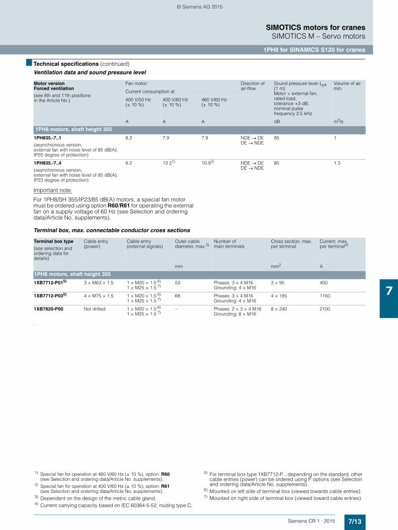
7/13Siemens CR 1 · 2015
7
■ Technical specifications (continued)
SIMOTICS motors for cranesSIMOTICS M – Servo motors
1PH8 for SINAMICS S120 for cranes
Ventilation data and sound pressure level
Important note:
For 1PH8/SH 355/IP23/85 dB(A) motors, a special fan motor must be ordered using option R60/R61 for operating the external fan on a supply voltage of 60 Hz (see Selection and ordering data/Article No. supplements).
Terminal box, max. connectable conductor cross sections
.
Motor version Forced ventilation
(see 8th and 11th positions in the Article No.)
Fan motor: Direction of air-flow
Sound pressure level LpA (1 m)Motor + external fan, rated load, tolerance +3 dB, nominal pulse frequency 2.5 kHz
Volume of air min.
Current consumption at
400 V/50 Hz (± 10 %)
400 V/60 Hz (± 10 %)
460 V/60 Hz (± 10 %)
A A A dB m3/s
1PH8 motors, shaft height 355
1PH835.-7..1
(asynchronous version, external fan with noise level of 85 dB(A), IP55 degree of protection)
8.2 7.9 7.9 NDE → DE DE → NDE
85 1
1PH835.-7..4
(asynchronous version, external fan with noise level of 85 dB(A), IP23 degree of protection)
8.2 13.21) 10.92) NDE → DE DE → NDE
85 1.3
Terminal box type
(see selection and ordering data for details)
Cable entry (power)
Cable entry (external signals)
Outer cable diameter, max.3)
Number of main terminals
Cross section, max. per terminal
Current, max. per terminal4)
mm mm2 A
1PH8 motors, shaft height 355
1XB7712-P015) 3 × M63 × 1.5 1 × M20 × 1.5 6)
1 × M25 × 1.5 7)53 Phases: 3 × 4 M16
Grounding: 4 × M163 × 95 450
1XB7712-P035) 4 × M75 × 1.5 1 × M20 × 1.5 6)
1 × M25 × 1.5 7)68 Phases: 3 × 4 M16
Grounding: 4 × M164 × 185 1150
1XB7820-P00 Not drilled 1 × M20 × 1.5 6)
1 × M25 × 1.5 7)– Phases: 2 × 3 × 4 M16
Grounding: 8 × M168 × 240 2100
1) Special fan for operation at 460 V/60 Hz (± 10 %), option: R60 (see Selection and ordering data/Article No. supplements).
2) Special fan for operation at 400 V/60 Hz (± 10 %), option: R61 (see Selection and ordering data/Article No. supplements).
3) Dependent on the design of the metric cable gland.4) Current carrying capacity based on IEC 60364-5-52, routing type C.
5) For terminal box type 1XB7712-P.., depending on the standard, other cable entries (power) can be ordered using P options (see Selection and ordering data/Article No. supplements).
6) Mounted on left side of terminal box (viewed towards cable entries).7) Mounted on right side of terminal box (viewed toward cable entries).
© Siemens AG 2015

7/14 Siemens CR 1 · 2015
7
SIMOTICS for cranesSIMOTICS M – Servo motors
1PH8 for SINAMICS S120 for cranes – Degree of protection IP23
■ Selection and ordering data
SIMOTICS M-1PH8 asynchronous motors, shaft height 355, type of construction IM B3
Overload factors for intermittent duty (S3) for 1PH835.-7..40-...0
Rated speed
Rated output
Ratedtorque
Rated current
Rated voltage
Ratedfrequency
Operating speed during field weaken-ing,max.1)
Max. speed2)
Max. torque 3)
Max. current4)
1PH8 asynchronous motorForced ventilation, IP23 degree of protection
nrated Prated Mrated Irated Urated frated n2 nmax Mmax at nrated
Imax
rpm kW Nm A V Hz rpm rpm Nm A Article No.
Supply voltage 480 V 3 AC, Active Line Module, Vector Control600 370 5889 530 500 30.4 1100 2800 12640 1310 1PH8350-7■B40-■■■0
415 6605 590 500 30.5 1100 2800 12500 1280 1PH8351-7■B40-■■■0
500 7958 700 500 30.5 1000 2800 15040 1490 1PH8352-7■B40-■■■0
590 9391 810 500 30.5 1000 2800 17050 1630 1PH8354-7■B40-■■■0
690 10983 940 500 30.5 900 2800 20690 1950 1PH8356-7■B40-■■■0
780 12415 1060 500 30.5 900 2800 23650 2200 1PH8358-7■B40-■■■0
800 480 5730 680 500 40.4 1400 2800 12910 1850 1PH8350-7■Q40-■■■0
530 6327 750 500 40.5 1400 2800 12830 1810 1PH8351-7■Q40-■■■0
630 7521 870 500 40.5 1300 2800 15280 2050 1PH8352-7■Q40-■■■0
750 8953 1040 500 40.4 1300 2800 19170 2480 1PH8354-7■Q40-■■■0
860 10266 1180 500 40.4 1200 2800 22380 2830 1PH8356-7■Q40-■■■0
960 11460 1300 500 40.5 1200 2800 23090 2860 1PH8358-7■Q40-■■■0
1000 600 5730 840 500 50.4 1500 2800 13470 2490 1PH8350-7■C40-■■■0
670 6399 940 500 50.5 1500 2800 13380 2470 1PH8351-7■C40-■■■0
780 7449 1080 500 50.5 1400 2800 14980 2540 1PH8352-7■C40-■■■0
900 8595 1220 500 50.5 1300 2800 17230 2790 1PH8354-7■C40-■■■0
1040 9932 1400 500 50.4 1200 2800 21370 3380 1PH8356-7■C40-■■■0
1200 11460 1700 480 50.4 1200 2800 27150 4400 1PH8358-7■C40-■■■0
1350 670 4740 920 500 68 1700 2800 9990 2450 1PH8350-7■D40-■■■0
750 5306 1040 500 68.1 1700 2800 9950 2400 1PH8351-7■D40-■■■0
910 6437 1240 500 68 1700 2800 13910 3310 1PH8352-7■D40-■■■0
1040 7357 1400 500 68 1400 2800 14180 3160 1PH8354-7■D40-■■■0
1200 8489 1600 500 67.9 1400 2800 19150 4130 1PH8356-7■D40-■■■0
1340 9479 1780 500 67.9 1400 2800 21870 4620 1PH8358-7■D40-■■■0
For versions, see Article No. supplements and options.
Operating modeOverload factor
S3-40 %1.47
S3-60 %1.23
© Siemens AG 2015

7/15Siemens CR 1 · 2015
7
■ Selection and ordering data (continued)
SIMOTICS for cranesSIMOTICS M – Servo motors
1PH8 for SINAMICS S120 for cranes – Degree of protection IP23
Motor type(repeated)
Max. torque3) Power factor
Magnetizing current
Efficiency Moment of inertia
Weight, approx.
Terminal box
Mmaxat1000 rpm 1500 rpm 2000 rpm 2500 rpm 2800 rpm
cos ϕ Iμ η J
Nm Nm Nm Nm Nm A kgm² kg Type
Supply voltage 480 V 3 AC, Active Line Module, Vector Control1PH8350-7.B4.-... 4840 2260 1320 870 580 0.85 194 0.946 14.74 2235 1XB7712-P01
1PH8351-7.B4.-... 4810 2260 1320 870 580 0.85 194 0.946 14.74 2235 1XB7712-P01
1PH8352-7.B4.-... 5770 2700 1570 1040 700 0.86 223 0.949 17.4 2560 1XB7712-P03
1PH8354-7.B4.-... 6550 3070 1790 1180 800 0.88 236 0.949 20.66 2889 1XB7712-P03
1PH8356-7.B4.-... 7930 3710 2160 1420 1000 0.88 285 0.952 24.22 3256 1XB7712-P03
1PH8358-7.B4.-... 9070 4240 2470 1630 1150 0.89 316 0.954 27.79 3629 1XB7712-P03
1PH8350-7.Q4.-... 8430 3890 2250 1470 1100 0.85 235 0.957 14.74 2235 1XB7712-P03
1PH8351-7.Q4.-... 8390 3880 2250 1470 1100 0.85 235 0.957 14.74 2235 1XB7712-P03
1PH8352-7.Q4.-... 9990 4610 2660 1740 1300 0.86 267 0.959 17.4 2560 1XB7712-P03
1PH8354-7.Q4.-... 12520 5770 3330 2170 1600 0.87 334 0.962 20.66 2889 1XB7712-P03
1PH8356-7.Q4.-... 14610 6730 3890 2540 1900 0.88 380 0.963 24.22 3256 1XB7820-P00
1PH8358-7.Q4.-... 15090 6980 4030 2640 1950 0.89 359 0.963 27.79 3629 1XB7820-P00
1PH8350-7.C4... 13470 6160 3540 2300 1850 0.85 294 0.962 14.74 2235 1XB7712-P03
1PH8351-7.C4... 13380 6140 3540 2300 1850 0.85 294 0.962 14.74 2235 1XB7712-P03
1PH8352-7.C4... 14980 6870 3950 2570 2070 0.87 302 0.963 17.4 2560 1XB7712-P03
1PH8354-7.C4... 17230 7910 4550 2970 2390 0.88 328 0.965 20.66 2889 1XB7820-P00
1PH8356-7.C4... 21370 9810 5640 3670 2960 0.88 410 0.967 24.22 3256 1XB7820-P00
1PH8358-7.C4... 27150 12430 7140 4650 3730 0.88 567 0.969 27.79 3629 1XB7820-P00
1PH8350-7.D4... 9990 8150 4670 3030 2430 0.86 235 0.965 14.74 2235 1XB7712-P03
1PH8351-7.D4... 9950 8120 4660 3030 2430 0.86 235 0.965 14.74 2235 1XB7712-P03
1PH8352-7.D4... 13910 11350 6500 4220 3390 0.87 338 0.969 17.4 2560 1XB7820-P00
1PH8354-7.D4... 14180 11570 6640 4320 3470 0.88 314 0.969 20.66 2889 1XB7820-P00
1PH8356-7.D4... 19150 15630 8960 5820 4680 0.88 433 0.972 24.22 3256 1XB7820-P00
1PH8358-7.D4... 21870 17840 10250 6660 5350 0.89 489 0.973 27.79 3629 1XB7820-P00
1) n2: Max. permissible thermal speed at constant output or speed, which is at the voltage limit when P = Prated.
2) nmax: Maximum speed that must not be exceeded.
3) Maximum torque which is briefly available for dynamic operations (e.g. when accelerating).
4) Maximum current which is briefly available for dynamic operations (e.g. when accelerating).
© Siemens AG 2015

7/16 Siemens CR 1 · 2015
7
■ Selection and ordering data (continued)
SIMOTICS for cranesSIMOTICS M – Servo motors
1PH8 for SINAMICS S120 for cranes – Degree of protection IP23
Overload factors for intermittent duty (S3) for 1PH835.-7..40-...0
Rated speed
Rated output
Rated torque
Rated current
Rated voltage
Ratedfrequency
Operating speed during field weakening, max.1)
Max. speed2)
Max. torque 3)
Max. current4)
1PH8 asynchronous motorForced ventilation, IP23 degree of protection
nrated Prated Mrated Irated Urated frated n2 nmax Mmax at nrated
Imax
rpm kW Nm A V Hz rpm rpm Nm A Article No.
Supply voltage 690 V 3 AC, Active Line Module, Vector Control600 370 5889 380 690 30.5 1100 2800 12620 950 1PH8350-7■H40-■■■0
415 6605 430 690 30.5 1100 2800 12490 930 1PH8351-7■H40-■■■0
500 7958 510 690 30.5 1000 2800 14450 1040 1PH8352-7■H40-■■■0
590 9391 590 690 30.5 1000 2800 17320 1200 1PH8354-7■H40-■■■0
690 10983 680 690 30.5 900 2800 20800 1420 1PH8356-7■H40-■■■0
780 12415 770 690 30.4 900 2800 24270 1630 1PH8358-7■H40-■■■0
800 480 5730 490 690 40.5 1400 2800 12600 1330 1PH8350-7■K40-■■■0
530 6327 540 690 40.5 1400 2800 12530 1300 1PH8351-7■K40-■■■0
630 7521 640 690 40.4 1300 2800 15760 1520 1PH8352-7■K40-■■■0
750 8953 740 690 40.5 1300 2800 18080 1710 1PH8354-7■K40-■■■0
860 10266 840 690 40.4 1200 2800 21500 1990 1PH8356-7■K40-■■■0
960 11460 940 690 40.4 1200 2800 23550 2110 1PH8358-7■K40-■■■0
1000 600 5730 610 690 50.5 1500 2800 13570 1810 1PH8350-7■U40-■■■0
670 6399 680 690 50.5 1500 2800 13480 1800 1PH8351-7■U40-■■■0
780 7449 780 690 50.5 1400 2800 15390 1870 1PH8352-7■U40-■■■0
900 8595 890 690 50.4 1300 2800 18240 2110 1PH8354-7■U40-■■■0
1040 9932 1020 690 50.5 1200 2800 20940 2420 1PH8356-7■U40-■■■0
1200 11460 1160 690 50.4 1200 2800 24680 2770 1PH8358-7■U40-■■■0
1350 670 4740 670 690 68.1 1700 2800 10260 1810 1PH8350-7■V40-■■■0
750 5306 750 690 68.1 1700 2800 10230 1840 1PH8351-7■V40-■■■0
910 6437 910 690 68 1700 2800 12720 2310 1PH8352-7■V40-■■■0
1040 7357 1040 690 68.1 1400 2800 13890 2270 1PH8354-7■V40-■■■0
1200 8489 1200 690 67.9 1400 2800 19270 3010 1PH8356-7■V40-■■■0
1340 9479 1340 690 68 1400 2800 20360 3120 1PH8358-7■V40-■■■0
For versions, see Article No. supplements and options.
Operating modeOverload factor
S3-40 %1.47
S3-60 %1.23
© Siemens AG 2015

7/17Siemens CR 1 · 2015
7
■ Selection and ordering data (continued)
SIMOTICS for cranesSIMOTICS M – Servo motors
1PH8 for SINAMICS S120 for cranes – Degree of protection IP23
Motor type(repeated)
Max. torque3) Power factor
Magnetizing current
Efficiency Moment of inertia
Weight, approx.
Terminal box
Mmaxat1000 rpm 1500 rpm 2000 rpm 2500 rpm 2800 rpm
cos ϕ Iμ η J
Nm Nm Nm Nm Nm A kgm² kg Type
Supply voltage 690 V 3 AC, Active Line Module, Vector Control1PH8350-7.H4... 4830 2250 1310 860 580 0.85 139 0.947 14.74 2235 1XB7712-P01
1PH8351-7.H4... 4810 2250 1310 870 580 0.85 139 0.947 14.74 2235 1XB7712-P01
1PH8352-7.H4... 5570 2610 1530 1010 700 0.87 149 0.946 17.4 2560 1XB7712-P03
1PH8354-7.H4... 6650 3110 1810 1190 800 0.88 176 0.95 20.66 2889 1XB7712-P03
1PH8356-7.H4... 7980 3730 2170 1430 1000 0.88 209 0.953 24.22 3256 1XB7712-P03
1PH8358-7.H4... 9320 4360 2540 1670 1160 0.88 245 0.955 27.79 3629 1XB7712-P03
1PH8350-7.K4... 8240 3810 2200 1440 1120 0.86 162 0.956 14.74 2235 1XB7712-P03
1PH8351-7.K4... 8200 3800 2200 1440 1120 0.86 162 0.956 14.74 2235 1XB7712-P03
1PH8352-7.K4... 10300 4750 2740 1790 1320 0.86 207 0.959 17.4 2560 1XB7712-P03
1PH8354-7.K4... 11820 5460 3160 2060 1500 0.88 215 0.96 20.66 2889 1XB7712-P03
1PH8356-7.K4... 14040 6470 3730 2440 1850 0.88 249 0.962 24.22 3256 1XB7820-P00
1PH8358-7.K4... 15410 7130 4120 2700 2000 0.89 272 0.964 27.79 3629 1XB7820-P00
1PH8350-7.U4... 13570 6200 3550 2310 1850 0.85 216 0.962 14.74 2235 1XB7712-P03
1PH8351-7.U4... 13480 6180 3550 2310 1860 0.85 216 0.962 14.74 2235 1XB7712-P03
1PH8352-7.U4... 15390 7050 4050 2640 2120 0.86 232 0.964 17.4 2560 1XB7712-P03
1PH8354-7.U4... 18240 8360 4810 3130 2520 0.87 269 0.966 20.66 2889 1XB7712-P03
1PH8356-7.U4... 20940 9590 5510 3580 2880 0.88 283 0.967 24.22 3256 1XB7712-P03
1PH8358-7.U4... 24680 11330 6530 4250 3420 0.88 339 0.968 27.79 3629 1XB7820-P00
1PH8350-7.V4... 10260 8360 4790 3100 2490 0.86 178 0.966 14.74 2235 1XB7712-P03
1PH8351-7.V4... 10230 8340 4780 3100 2490 0.86 178 0.966 14.74 2235 1XB7712-P03
1PH8352-7.V4... 12720 10400 6000 3920 3150 0.87 208 0.967 17.4 2560 1XB7712-P03
1PH8354-7.V4... 13890 11330 6490 4220 3390 0.88 219 0.968 20.66 2889 1XB7712-P03
1PH8356-7.V4... 19270 15730 9020 5870 4710 0.88 317 0.972 24.22 3256 1XB7820-P00
1PH8358-7.V4... 20360 16620 9540 6200 4990 0.89 322 0.972 27.79 3629 1XB7820-P00
1) n2: Max. permissible thermal speed at constant output or speed, which is at the voltage limit when P = Prated.
2) nmax: Maximum speed that must not be exceeded.
3) Maximum torque which is briefly available for dynamic operations (e.g. when accelerating).
4) Maximum current which is briefly available for dynamic operations (e.g. when accelerating).
© Siemens AG 2015

7/18 Siemens CR 1 · 2015
7
■ Selection and ordering data (continued)
SIMOTICS for cranesSIMOTICS M – Servo motors
1PH8 for SINAMICS S120 for cranes – Degree of protection IP55
SIMOTICS M-1PH8 asynchronous motors, shaft height 355, type of construction IM B3
Overload factors for intermittent duty (S3) for 1PH835.-7..10-...0
Rated speed
Rated output
Rated torque
Rated current
Rated volt-age
Ratedfrequency
Operating speed during field weaken-ing, max.1)
Max. speed2)
Max. torque 3)
Max. current4)
1PH8 asynchronous motorForced ventilation, IP55 degree of protection
nrated Prated Mrated Irated Urated frated n2 nmax Mmax at nrated
Imax
rpm kW Nm A V Hz rpm rpm Nm A Article No.
Supply voltage 480 V 3 AC, Active Line Module, Vector Control600 230 3661 350 500 30.3 1400 2800 12120 1260 1PH8350-7■B10-■■■0
275 4377 410 500 30.3 1400 2800 14570 1440 1PH8352-7■B10-■■■0
325 5173 475 500 30.3 1400 2800 16670 1590 1PH8354-7■B10-■■■0
380 6048 550 500 30.3 1400 2800 20320 1920 1PH8356-7■B10-■■■0
430 6844 620 500 30.2 1400 2800 23390 2180 1PH8358-7■B10-■■■0
800 300 3581 450 500 40.3 1400 2800 12500 1790 1PH8350-7■Q10-■■■0
360 4298 530 500 40.3 1400 2800 14870 1990 1PH8352-7■Q10-■■■0
420 5014 620 500 40.3 1400 2800 19960 2580 1PH8354-7■Q10-■■■0
490 5849 720 500 40.2 1400 2800 22050 2790 1PH8356-7■Q10-■■■0
565 6745 790 500 40.3 1400 2800 22770 2820 1PH8358-7■Q10-■■■0
1000 360 3438 540 500 50.3 1500 2800 13150 2430 1PH8350-7■C10-■■■0
430 4107 620 500 50.3 1500 2800 14700 2490 1PH8352-7■C10-■■■0
505 4823 720 500 50.3 1500 2800 16970 2750 1PH8354-7■C10-■■■0
580 5539 830 500 50.3 1600 2800 21120 3340 1PH8356-7■C10-■■■0
670 6399 1040 480 50.2 1600 2800 26910 4360 1PH8358-7■C10-■■■0
1350 380 2688 540 500 67.8 1800 2800 9840 2410 1PH8350-7■D10-■■■0
460 3254 670 500 67.7 1800 2800 13690 3260 1PH8352-7■D10-■■■0
550 3891 760 500 67.8 1700 2800 14050 3130 1PH8354-7■D10-■■■0
630 4457 900 500 67.7 1700 2800 18980 4090 1PH8356-7■D10-■■■0
730 5164 1040 500 67.7 1700 2800 21720 4590 1PH8358-7■D10-■■■0
For versions, see Article No. supplements and options.
Operating modeOverload factor
S3-40 %1.47
S3-60 %1.23
© Siemens AG 2015

7/19Siemens CR 1 · 2015
7
■ Selection and ordering data (continued)
SIMOTICS for cranesSIMOTICS M – Servo motors
1PH8 for SINAMICS S120 for cranes – Degree of protection IP55
Motor type(repeated)
Max. torque3) Power factor
Magnetizing current
Efficiency Moment of inertia
Weight, approx.
Terminal box
Mmaxat1000 rpm 1500 rpm 2000 rpm 2500 rpm 2800 rpm
cos ϕ Iμ η J
Nm Nm Nm Nm Nm A kgm² kg Type
Supply voltage 480 V 3 AC, Active Line Module, Vector Control1PH8350-7.B1... 4710 2220 1310 860 580 0.79 194 0.959 14.74 2235 1XB7712-P01
1PH8352-7.B1... 5640 2660 1560 1030 700 0.8 223 0.961 17.4 2560 1XB7712-P01
1PH8354-7.B1... 6450 3030 1780 1170 800 0.82 236 0.962 20.66 2889 1XB7712-P03
1PH8356-7.B1... 7840 3680 2150 1420 980 0.82 285 0.964 24.22 3256 1XB7712-P03
1PH8358-7.B1... 8990 4210 2460 1620 1100 0.82 316 0.965 27.79 3629 1XB7712-P03
1PH8350-7.Q1... 8210 3830 2230 1460 1050 0.8 235 0.964 14.74 2235 1XB7712-P03
1PH8352-7.Q1... 9750 4540 2640 1730 1250 0.81 267 0.966 17.40 2560 1XB7712-P03
1PH8354-7.Q1... 12960 5910 3390 2200 1690 0.8 334 0.967 20.66 2889 1XB7712-P03
1PH8356-7.Q1... 14420 6670 3860 2520 1850 0.81 380 0.968 24.22 3256 1XB7712-P03
1PH8358-7.Q1... 14930 6930 4020 2640 1890 0.84 359 0.969 27.79 3629 1XB7712-P03
1PH8350-7.C1... 13150 6070 3510 2290 1850 0.79 294 0.967 14.74 2235 1XB7712-P03
1PH8352-7.C1... 14700 6780 3910 2550 2060 0.82 302 0.969 17.40 2560 1XB7712-P03
1PH8354-7.C1... 16970 7830 4530 2960 2380 0.83 328 0.97 20.66 2889 1XB7712-P03
1PH8356-7.C1... 21120 9730 5610 3660 2950 0.82 410 0.971 24.22 3256 1XB7712-P03
1PH8358-7.C1... 26910 12360 7120 4640 3730 0.8 567 0.971 27.79 3629 1XB7712-P03
1PH8350-7.D1... 9840 8040 4620 3010 2420 0.83 235 0.97 14.74 2235 1XB7712-P03
1PH8352-7.D1... 13690 11180 6430 4190 3370 0.81 338 0.97 17.4 2560 1XB7712-P03
1PH8354-7.D1... 14050 11480 6620 4310 3470 0.85 314 0.972 20.66 2889 1XB7712-P03
1PH8356-7.D1... 18980 15500 8910 5800 4660 0.83 433 0.972 24.22 3256 1XB7712-P03
1PH8358-7.D1... 21720 17740 10220 6660 5360 0.83 489 0.972 27.79 3629 1XB7712-P03
1) n2: Max. permissible thermal speed at constant output or speed, which is at the voltage limit when P = Prated.
2) nmax: Maximum speed that must not be exceeded.
3) Maximum torque which is briefly available for dynamic operations (e.g. when accelerating).
4) Maximum current which is briefly available for dynamic operations (e.g. when accelerating).
© Siemens AG 2015
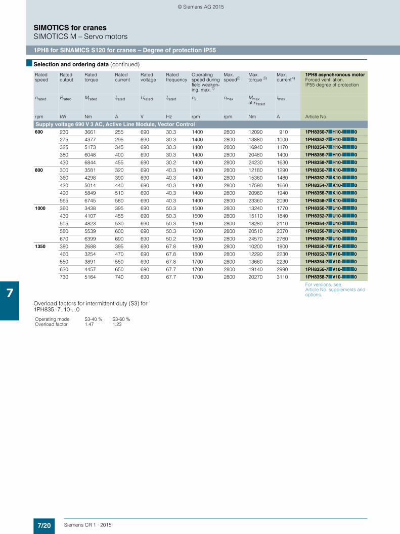
7/20 Siemens CR 1 · 2015
7
■ Selection and ordering data (continued)
SIMOTICS for cranesSIMOTICS M – Servo motors
1PH8 for SINAMICS S120 for cranes – Degree of protection IP55
Overload factors for intermittent duty (S3) for 1PH835.-7..10-...0
Ratedspeed
Rated output
Rated torque
Rated current
Rated voltage
Ratedfrequency
Operating speed during field weaken-ing, max.1)
Max. speed2)
Max. torque 3)
Max. current4)
1PH8 asynchronous motorForced ventilation, IP55 degree of protection
nrated Prated Mrated Irated Urated frated n2 nmax Mmax at nrated
Imax
rpm kW Nm A V Hz rpm rpm Nm A Article No.
Supply voltage 690 V 3 AC, Active Line Module, Vector Control600 230 3661 255 690 30.3 1400 2800 12090 910 1PH8350-7■H10-■■■0
275 4377 295 690 30.3 1400 2800 13880 1000 1PH8352-7■H10-■■■0
325 5173 345 690 30.3 1400 2800 16940 1170 1PH8354-7■H10-■■■0
380 6048 400 690 30.3 1400 2800 20480 1400 1PH8356-7■H10-■■■0
430 6844 455 690 30.2 1400 2800 24230 1630 1PH8358-7■H10-■■■0
800 300 3581 320 690 40.3 1400 2800 12180 1290 1PH8350-7■K10-■■■0
360 4298 390 690 40.3 1400 2800 15360 1480 1PH8352-7■K10-■■■0
420 5014 440 690 40.3 1400 2800 17590 1660 1PH8354-7■K10-■■■0
490 5849 510 690 40.3 1400 2800 20960 1940 1PH8356-7■K10-■■■0
565 6745 580 690 40.3 1400 2800 23360 2090 1PH8358-7■K10-■■■0
1000 360 3438 395 690 50.3 1500 2800 13240 1770 1PH8350-7■U10-■■■0
430 4107 455 690 50.3 1500 2800 15110 1840 1PH8352-7■U10-■■■0
505 4823 530 690 50.3 1500 2800 18280 2110 1PH8354-7■U10-■■■0
580 5539 600 690 50.3 1600 2800 20510 2370 1PH8356-7■U10-■■■0
670 6399 690 690 50.2 1600 2800 24570 2760 1PH8358-7■U10-■■■0
1350 380 2688 395 690 67.8 1800 2800 10200 1800 1PH8350-7■V10-■■■0
460 3254 470 690 67.8 1800 2800 12290 2230 1PH8352-7■V10-■■■0
550 3891 550 690 67.8 1700 2800 13660 2230 1PH8354-7■V10-■■■0
630 4457 650 690 67.7 1700 2800 19140 2990 1PH8356-7■V10-■■■0
730 5164 740 690 67.7 1700 2800 20270 3110 1PH8358-7■V10-■■■0
For versions, see Article No. supplements and options.
Operating modeOverload factor
S3-40 %1.47
S3-60 %1.23
© Siemens AG 2015

7/21Siemens CR 1 · 2015
7
■ Selection and ordering data (continued)
SIMOTICS for cranesSIMOTICS M – Servo motors
1PH8 for SINAMICS S120 for cranes – Degree of protection IP55
Motor type(repeated)
Max. torque3) Power factor
Magnetizing current
Efficiency Moment of inertia
Weight, approx.
Terminal box
Mmaxat1000 rpm 1500 rpm 2000 rpm 2500 rpm 2800 rpm
cos ϕ Iμ η J
Nm Nm Nm Nm Nm A kgm² kg Type
Supply voltage 690 V 3 AC, Active Line Module, Vector Control1PH8350-7.H1... 4690 2210 1300 860 580 0.79 139 0.959 14.74 2235 1XB7712-P01
1PH8352-7.H1... 5390 2550 1500 990 680 0.81 149 0.96 17.4 2560 1XB7712-P01
1PH8354-7.H1... 6550 3080 1810 1190 820 0.82 176 0.962 20.66 2889 1XB7712-P01
1PH8356-7.H1... 7890 3700 2160 1430 1000 0.82 209 0.964 24.22 3256 1XB7712-P01
1PH8358-7.H1... 9310 4350 2540 1670 1160 0.81 242 0.965 27.79 3629 1XB7712-P03
1PH8350-7.K1... 8010 3740 2180 1430 1000 0.8 162 0.965 14.74 2235 1XB7712-P01
1PH8352-7.K1... 10070 4670 2710 1780 1290 0.8 207 0.966 17.40 2560 1XB7712-P01
1PH8354-7.K1... 11560 5390 3140 2060 1490 0.82 215 0.969 20.66 2889 1XB7712-P03
1PH8356-7.K1... 13760 6400 3720 2440 1800 0.83 249 0.969 24.22 3256 1XB7712-P03
1PH8358-7.K1... 15290 7080 4100 2680 2010 0.84 272 0.969 27.79 3629 1XB7712-P03
1PH8350-7.U1... 13240 6110 3530 2310 1860 0.78 216 0.967 14.74 2235 1XB7712-P01
1PH8357-7.U1... 15110 6960 4010 2620 2110 0.81 232 0.968 17.40 2560 1XB7712-P01
1PH8354-7.U1... 18280 8430 4860 3180 2560 0.82 269 0.97 20.66 2889 1XB7712-P03
1PH8356-7.U1... 20510 9450 5450 3560 2860 0.83 283 0.971 24.22 3256 1XB7712-P03
1PH8358-7.U1... 24570 11310 6520 4250 3420 0.83 339 0.971 27.79 3629 1XB7712-P03
1PH8350-7.V1... 10200 8320 4780 3110 2500 0.83 178 0.97 14.74 2235 1XB7712-P01
1PH8352-7.V1... 12290 10040 5780 3760 3030 0.84 208 0.971 17.4 2560 1XB7712-P03
1PH8354-7.V1... 13660 11160 6420 4180 3360 0.86 219 0.972 20.66 2889 1XB7712-P03
1PH8356-7.V1... 19140 15630 8980 5840 4700 0.83 317 0.972 24.22 3256 1XB7712-P03
1PH8358-7.V1... 20270 16550 9510 6190 4970 0.85 322 0.973 27.79 3629 1XB7712-P03
1) n2: Max. permissible thermal speed at constant output or speed, which is at the voltage limit when P = Prated.
2) nmax: Maximum speed that must not be exceeded.
3) Maximum torque which is briefly available for dynamic operations (e.g. when accelerating).
4) Maximum current which is briefly available for dynamic operations (e.g. when accelerating).
© Siemens AG 2015

7/22 Siemens CR 1 · 2015
7
■ Selection and ordering data (continued)
SIMOTICS for cranesSIMOTICS M – Servo motors
Article No. supplements
Position of the Article No. 1 2 3 4 5 6 7 8 9 10 11 12 13 14 15 16
Shaft height 355 1 P H 8 3 5 . – 7 ■ . ■ ■ – ■ ■ ■ 0 – Z
Overall length1) .
Asynchronous variant
Forced ventilation with noise value 85 dB 7
Encoder systems for motors without DRIVE-CLiQ interface
Without encoder A
Prepared for encoder mounting systems2)
Incremental encoder HTL 1024 S/R with solid shaft Mounting of incremental encoder POG 10 D 1024
Order code required: H56 K
Incremental encoder HTL 1024 S/R with solid shaftIncremental encoder POG 10 supplied by customer
Order code required: G80 K
Incremental encoder HTL 1024 S/R with hollow shaft Incremental encoder HOG 28 supplied by customer
Order code required: H75 G
Rated speed (winding version) .
Cooling Degree of protection
Forced ventilation IP55 1
Forced ventilation IP23 (open-circuit cooling) 4
Type
IM B3 0
Shaft extension (DE) Balancing
Featherkey Full-key 1
Featherkey Half-key 2
Bearings Vibration magnitude acc. to
Shaft and flange accuracy3)
Standard A N A
Standard R/A R B
Cable connection (view of DE)
Terminal box Cable infeed External fan NDE with air inlet from NDEAir-flow direction NDE →
NDE right Bottom Top U
Left Order code required: G00 U – Z
NDE left Bottom Top V
Right Order code required: G02 V – Z
NDE top Right Left Order code required: G00 W – Z
Right Order code required: G02 W – Z
DE top4) Right Top5) X
Left Order code required: G00 X – Z
Right Order code required: G02 X – Z
Version status
Shaft height 355 0
Special versions Order No. supplement "-Z" with order code and plain text if required, see options. – Z
1) Not selectable. Determined by the choice of rated power.2) For more information on incremental encoders, visit
www.baumerhuebner.com
3) For definition, see 1PH8 Configuration Manual.4) Signal connection for 1PH835 NDE at bearing shield.5) Only possible for assignments with terminal box 1XB7712-P..
© Siemens AG 2015

7/23Siemens CR 1 · 2015
7
SIMOTICS for cranesSIMOTICS M – Servo motors
Options
■ Options
Order No. supplement "-Z" with order code and plain text, if re-quired.
Order code Description
A08 Air flow monitoring 24 V DC
A31 Motor temperature monitoring through switch
A60 Motor protection through 3 × Pt100
A72 Bearing temperature monitoring with Pt100
G00 External fan NDE left (possible if 15th position of Article No. is U, W or X)
G02 External fan NDE right (possible if 15th position of Article No. is V, W or X)
G14 With air filter
G80 Mounting of a supplied POG 10 incremental encoder (possible if 9th position of Article No. is K)
H56 Mounting of a POG 10 DN 1024 incremental encoder (HTL 1024 S/R; possible if 9th position of Article No. is K)
H75 Mounting of a supplied HOG 28 incremental encoder (possible if 9th position of Article No. is G)
K12 Additional PTC thermistor chain for alarm and tripping
K16 Second shaft extension 120 mm × 210 mm (d × l; possible if 9th position of Article No. = "A" or "G")
K45 230 V standstill heating
K46 110 V standstill heating
K83 Terminal box rotated through +90° (possible if 15th position of Article No. is V or W)
K84 Terminal box rotated through -90° (possible if 15th position of Article No. is U or W)
K85 Terminal box rotated through +180°
L00 Terminal box 1XB7820 (cable entry plate undrilled) instead of terminal box 1XB7712
L12 Condensation water drain hole provided unsealed
L29 Enhanced corrosion protection (possible if 11th position of Article No. is 1)
L50 Adapter base for mounting a fan
P00 Cable entry plate undrilled (with terminal box 1XB7712 only)
P01 Cable entry plate 3 × M63 × 1.5 (only with terminal box 1XB7712)
P02 Cable entry plate 3 × M75 × 1.5 (only with terminal box 1XB7712)
P03 Cable entry plate 4 × M75 × 1.5 (only with terminal box 1XB7712)
P04 Cable entry plate 4 × M63 × 1.5 (only with terminal box 1XB7712)
P12 Cable entry plate 6 × M63 × 1.5 + 2 × M20 (only with terminal box 1XB7820)
P13 Cable entry plate 7 × M50 × 1.5 + 2 × M20 + 1 × M25 (only with terminal box 1XB7820)
P14 Cable entry plate 6 × M63 × 1.5 + 1 × M20 + 1 × M25 (only with terminal box 1XB7820)
P15 Cable entry plate 9 × M63 × 1.5 + 1 × M20 + 1 × M25 (only with terminal box 1XB7820)
P16 Cable entry plate 12 × M63 × 1.5 + 1 × M20 + 1 × M25 (only with terminal box 1XB7820)
Q00 Increased number of ground terminals in the terminal box (12 × M6 for 1XB771, 24 × M6 for 1XB7280)
R60 Special fan for operation at 460 V / 60 Hz (±10 %)
R61 Special fan for operation at 400 V / 60 Hz (±10 %)
Y84 Customer-specific information on rating plate (maximum 30 characters)1)
Colors
– Standard paint is anthracite RAL 7016
X01 Standard finish in RAL 9005 (black)
K24 Primer
K23 Special paint finish worldwide (anthracite RAL 7016)
K23+X.. Special paint finish worldwide in another color X.. (on request)
1) Specify plain text when ordering.
© Siemens AG 2015

7/24 Siemens CR 1 · 2015
7
■ Options (continued)
SIMOTICS for cranesSIMOTICS M – Servo motors
Options
Ordering example
Selection criteria Requirement Structure of the Article No.
Motor type Asynchronous motor, shaft height 355, IP55 degree of protection, type of construction IM B3,noise level 85 dB(A), operating speed 800 rpm,Supply voltage 690 V 3 ACIntermittent duty S3-60 %Rated output 445 kWRated torque 5312 Nm,Rated current 460 A, Terminal box type 1XB7712-P01
1PH8352-7■K10-■■■0
Encoder systems Incremental encoder HTL 1024 S/R POG 10 (Baumer-Hübner), prepared for mounting
1PH8352-7KK10-■■■0
Shaft extension (DE)/balancing Featherkey + full-key balancing 1PH8352-7KK10-1■■0
Bearings Standard (A/N) 1PH8352-7KK10-1A■0
Terminal box DE top, cable entry right 1PH8352-7KK10-1AX0
Special versionMounting of a supplied pulse encoder with POG 10 mounting flange
1PH8352-7KK10-1AX0-Z G80
230 V standstill heating 1PH8352-7KK10-1AX0-ZG80+K45
Cable entry plate 4 × M75 × 1.5 1PH8352-7KK10-1AX0-ZG80+K45+P03
Complete ordering information for required version of motor 1PH8352-7KK10-1AX0-ZG80+K45+P03
© Siemens AG 2015

7/25Siemens CR 1 · 2015
7
SIMOTICS motors for cranesSIMOTICS M – Servo motors
Dimensional drawings
■ Dimensional drawings
Shaft height Dimensions to IEC
1PH8... A AA AB AC B BA BB C CA CA1 W5 W6 D DA DB DC E EA EB EC ED EE
350/351 670 130 760 781 772 317 1150 254 254 375 243 795 Ø130 Ø120 M24 M24 250 210 220 180 25 25
352 670 130 760 781 862 317 1240 254 254 375 243 885 Ø130 Ø120 M24 M24 250 210 220 180 25 25
354 670 130 760 781 972 317 1350 254 254 375 243 995 Ø130 Ø120 M24 M24 250 210 220 180 25 25
356 670 130 760 781 1092 317 1470 254 254 375 243 1115 Ø130 Ø120 M24 M24 250 210 220 180 25 25
358 670 130 760 781 1212 317 1590 254 254 375 243 1235 Ø130 Ø120 M24 M24 250 210 220 180 25 25
2nd shaft extension 2nd shaft extension + HOG28
AIAO
Air inlet
Space for mounting filter
Air outlet
AO
AI
G_C
R01
_EN
_002
07a
DNP
K
HA
K1
C
W6W5LA
T
B
K4K3
1)
POG10
BC1E
EBED
BBL
ASAG
AAA
ABAC
HH
CA
DHD
BAM1
DB
L1 LC
ECEEEACA
ECEEEACA1
L2LC1
K2
DA
DA
DC DC
GF
GB
GC
GH
FA
BCLL
LE
M
ZxS
AS
AG
AD
GD
GE
GA
GF
3001)
Shaft height Dimensions to IEC1PH8... F FA G GA GB GC GD GE GF GH H HA HC K L L1 L2 LC LC1350/351 32 32 119 137 114 127 18 11 18 11 355 26 735 Ø28 1523 1625 1644 1740 1861352 32 32 119 137 114 127 18 11 18 11 355 26 735 Ø28 1613 1715 1734 1830 1951354 32 32 119 137 114 127 18 11 18 11 355 26 735 Ø28 1723 1825 1844 1940 2061356 32 32 119 137 114 127 18 11 18 11 355 26 735 Ø28 1843 1945 1964 2060 2181358 32 32 119 137 114 127 18 11 18 11 355 26 735 Ø28 1963 2065 2084 2180 2301
Shaft height Terminal box Fan Flange1PH8... AD AG DE BC BC1 LL K1 K2 K3 K4 HD LA LE M M1 N P S T Z
1 XB7 820 85 dB (A)350/351 784 492 245 151 861 696 844 1438 282 355 1578 25 250 Ø740 40 Ø680 Ø800 Ø24 6 8352 784 492 245 151 951 696 934 1528 282 355 1578 25 250 Ø740 40 Ø680 Ø800 Ø24 6 8354 784 492 245 151 1061 696 1044 1638 282 355 1578 25 250 Ø740 40 Ø680 Ø800 Ø24 6 8356 784 492 245 151 1181 696 1164 1758 282 355 1578 25 250 Ø740 40 Ø680 Ø800 Ø24 6 8358 784 492 245 151 1301 696 1284 1878 282 355 1578 25 250 Ø740 40 Ø680 Ø800 Ø24 6 8
1 XB7 712 R60/R61 fan 60 Hz350/351 640 377 201 –12 784 370 802 1438 282 355 1578
352 640 377 201 –12 874 370 892 1528 282 355 1578
354 640 377 201 –12 984 370 1002 1638 282 355 1578
356 640 377 201 –12 1104 370 1122 1758 282 355 1578
358 640 377 201 –12 1224 370 1242 1878 282 355 1578
© Siemens AG 2015

7/26 Siemens CR 1 · 2015
7
SIMOTICS motors for cranesSIMOTICS SD – Severe Duty motors
1LP4, 1LP6 with mounted spring-set brake
■ Overview
Three-phase asynchronous motor 1LP with fitted DC-excited spring-set brake
The naturally cooled crane motors of type 1LP4 and 1LP6 form a compact drive unit when combined with the mounted spring-set brake and are ideal for application as traversing mo-tors. The DC-operated brake is designed as a holding brake, but is also capable of emergency shutdown braking operations at maximum motor speed. In the case of power failure, the brake is applied automatically by its spring force and brings the drive to a standstill.
Product range
The product range includes shaft heights 132 S to 280 M in the 5.5 to 132 kW power range for 4-pole motors, or in the 3 to 90 kW power range for 6-pole motors, for duty type S3-25 % in each case. As the table below shows, more than one type of brake can be fitted to a motor; this flexibility allows the user to tailor the drive unit – comprising the motor and brake – to the exact requirements of the crane manufacturer.
The motors can also be ordered without a brake. The same ar-ticle numbers apply, but the article number supplements for the brake are excluded.
Motor shaft height
Brake type
KFB 10 KFB 16 KFB 25 KFB 30 KFB 40 KFB 63 KFB 100 KFB 160
100 Nm 160 Nm 250 Nm 300 Nm 400 Nm 630 Nm 1000 Nm 1600 Nm
132
160
180
200
225
250
280
© Siemens AG 2015

7/27Siemens CR 1 · 2015
7
SIMOTICS motors for cranesSIMOTICS SD – Severe Duty motors
1LP4, 1LP6 with mounted spring-set brake
■ Technical specifications
Electrical design
Operating voltage
The crane brake motors are available for the following rated voltages:• 400 V 3 AC, 50 Hz• 460 V 3 AC, 50 Hz• 500 V 3 AC, 50 Hz• 690 V 3 AC, 50 Hz
The specifications change as follows for motors operating at a rated frequency of 60 Hz:• Rated speed +20 %• Rated power +15 %
The standard model of brake coil is supplied for connection to 207 V DC (see technical specifications for brakes).
Motor protection
The following protective equipment can be installed (see "Article number supplements and special versions"):• 3 PTC thermistors for tripping• 3 PTC thermistors for tripping and 3 PTC thermistors for alarm• 1 KTY 84-130 temperature sensor for evaluation in the conver-
ter• 3 bimetallic switches (Klixon) for tripping
Standstill heating
The motors can be fitted with a standstill heater. The heat outputs are as follows:
For voltages, see "Article number supplements and special versions".
It is also possible to connect a voltage (which should equal approximately 4 to 10 % of the rated motor voltage) to stator terminals U1 and V1. 20 to 30 % of the rated motor current is normally sufficient to provide adequate heating.
Insulation
The motor windings are designed to comply with insulation class F.
Electric strength
See Catalog D 81.1.
Mechanical design
1LP4/1LP6 motors are naturally cooled units without fans. Depending on the shaft height, brakes with different torques can be built onto the motors. Housing and terminal box are made of gray cast iron. The brake itself does not have a separate terminal box; all the brake connections, whether coil, microswitch or hea-ter, are taken to the motor terminal box.
Types of construction
The motors are available in types of construction IM B3, IM B35, IM V5, IM B5 and IM V1. Other types of construction are avail-able on request.The position of the condensate drain holes is determined by the type of construction.
Housing
The housing and terminal box of the motor are made of gray cast iron. The DE flange and the feet (bolted-on) can be supplied in GGG 40 as an option.
Degree of protection
The degree of protection of the standard motor models is IP55. IP56 is also available as an option. The water drain holes on mo-tors with this degree of protection must be opened at regular in-tervals as part of the maintenance cycle to allow any condensate that has collected inside the motor to drain off.
Paint finish
The motors are coated as standard in a special finish RAL 7030 with a coat thickness of 180 μm. Other colors are available at ad-ditional cost. A further option is an offshore finish with a coat thickness of 220 μm.
Mounted equipment
Sensing equipment such as the POG 10 incremental encoder (made by Baumer Hübner) can be mounted on the motors. The brakes themselves can be supplied with an emergency manual release mechanism (see KFB spring-set brake for SIMOTICS SD 1LP4/1LP6, special versions "Emergency release with hand le-ver").
Motor shaft height Heat output
W
132 ... 160 100
180 ... 200 55
225 ... 250 92
280 109
© Siemens AG 2015

7/28 Siemens CR 1 · 2015
7
■ Technical specifications (continued)
SIMOTICS motors for cranesSIMOTICS SD – Severe Duty motors
1LP4, 1LP6 with mounted spring-set brake
Terminal box
On standard models, the terminal box is mounted on the top at the DE and is always the next size larger than on the basic mo-dels of the 1LG motor. The feet are cast on.
The terminal box can also be positioned on the left or right (as viewed from the DE), but this option is only possible on motors with bolted-on feet. If the motor is to have bolted-on feet and a terminal box positioned on top, options K11 and J22 must be selected in the order.
On motors with a brake, the terminal box is fitted at the NDE. The option M64 must be specified additionally.
All connecting terminals for the motor and brake including auxi-liaries are housed in the motor terminal box.
Auxiliary terminal designations
Shaft extension
Standard brake motors are designed with a cylindrical shaft extension.
Maximum speed
The maximum permissible speed is 3000 rpm.
Bearing
Motor shaft height
Terminal box
Clamping bolt
Conductor cross-section, max.
Entry hole1)
Sealing range
mm2 mm
132, 160 GT320 M5 16 M40 × 1.5 19 to 28
180 GT4212) M5 16 M40 × 1.5 19 to 28
200 GT591 M6 25 M50 × 1.5 27 to 35
225 GT591 M8 35 M50 × 1.5 27 to 35
250, 280 GT591 M10 120 M63 × 1.5 32 to 42
Temperature sensor Terminal designation
3 PTC thermistors for alarm 1TP1-1TP2
3 PTC thermistors for tripping 2TP1-2TP2
Bimetallic (NC contact) 2TP1-2TP2
Standstill heater (motor) HE1-HE2
Brake coil DC BA1-BA2
Brake coil AC BD1-BD2
Standstill heater (brake) BRHE1-BRHE2
Microswitch brake opened BRS1-BRS3
Microswitch brake air gap monitoring BRS1-BRS3
Motor shaft height DE bearing NDE bearing
132 6208 2ZC3 6208 2ZC3
160 6209 2ZC3 6209 2ZC3
180 6210 ZC3 6210 ZC3
200 6212 ZC3 6212 ZC3
225 6213 ZC3 6213 ZC3
250 6215 ZC3 6215 ZC3
280 6217 C3 6217 C3
1) If the motor has been ordered with temperature sensor, an extra M20 × 1.5 hole is provided. If the motor has been ordered with heater, an extra M20 × 1.5 hole is provided.
2) Identical in construction to GK340.
© Siemens AG 2015

7/29Siemens CR 1 · 2015
7
SIMOTICS motors for cranesSIMOTICS SD – Severe Duty motors
KFB spring-set brake for SIMOTICS SD 1LP4, 1LP6
■ Design
The electromagnetic double-disc spring-set brake KFB, see picture "KFB spring-set brake with manual lever", is intended to operate solely as a holding brake for this application. With the exception of emergency braking, it may only be operated as a dynamically loaded operational brake if it is appropriately di-mensioned or after consultation with the manufacturer. It is a spring-loaded, electrically operated, double-disc brake, which operates when the power is switched off. When the coil (2) is energized with a DC voltage, the brake is released electromag-netically. If the coil (2) is de-energized, the springs (6) press the armature plate (4) axially against the friction-lining carrier (5) which in turn presses against the brake flange (7); this sequence provides the braking action. The brake is released when the coil (2) is energized. The magnetic field attracts the armature plate (4) towards the coil form (1), counteracting the spring pressure on the coil form. The air gap can be adjusted within a wide range, ensuring high availability of the brake. The motor and brake are coupled by means of a flange (12). Emergency brake release is possible by means of 2 emergency release screws – optionally with hand lever release.
As a result of the compact design with the enclosed coil form housing and appropriate sealing from the shaft, the brake has degree of protection IP67 when the housing is closed.
All the brake connections such as coil, microswitch, etc. are taken to the motor terminal box.
KFB spring-set brake with manual lever
Rotary encoder POG10Tacho bushing T2 with coupling and assembly componentsKFB brakeIEC mounting flangeHand lever for emergency release (option)
12345
G_CR01_EN_00060
1234
5
Coil formCoilHubArmature plate
Friction-lining carrierSpringsBrake flangeHand lever
HousingTacho assemblycomponentsService screwMounting flange
1234
5678
910
1112
G_C
R01
_EN
_000
59
8
7
9
3
5
41126112
10
© Siemens AG 2015

7/30 Siemens CR 1 · 2015
7
■ Design (continued)
SIMOTICS motors for cranesSIMOTICS SD – Severe Duty motors
KFB spring-set brake for SIMOTICS SD 1LP4, 1LP6
Protective element
The brakes should be connected at the DC end, i.e. between the rectifier and coil (see circuit diagram below). This ensures a sig-nificantly shorter closing time than if the brake were connected at the AC end. A protective element (varistor + spark quen-ching) must be fitted in parallel to each brake coil. This protects the brake coil against excessively high de-energization voltages on the one hand, and the contactor contacts on the other. These protective elements must be installed close to the brake coils where possible, e.g. in the motor terminal box or in a distribution board on the subframes in the case of traversing gear. Protective elements PE-400/150/5 are directly available from the manufacturer1) under Article No. 008099300249.
Technical specifications
Special versions
Emergency release with hand lever, option J25
In addition to brake release at zero current via 2 emergency re-lease screws, it is also possible to release the brake by means of a hand lever permanently mounted on the brake housing. The lever is lockable.
Microswitch for "brake released" monitoring, option J26
The brake can be fitted with a microswitch for monitoring the "brake released" state. The contact is rated for:• < 30 V DC, 5.0 A• < 125 V DC, 0.5 A• < 250 V AC, 5.0 A
Microswitch for air gap monitoring/wear, option J24
A 2nd microswitch can be fitted to monitor the "maximum air gap" function. Tripping of this contact indicates that full braking power is no longer available and the air gap must be adjusted immediately. The contact load rating is identical to that of the "brake released" microswitch.
Standstill heater, option J27
The installation of a heater can prevent the formation of conden-sate, e.g. caused by fluctuations in temperature and air humi-dity, inside the brake. This heater must not be switched on when the motor is operating. The heater is designed for a supply vol-tage of 230 V AC and a heat output of 40 W.
Encoder mounting, option J28/J29
An encoder (e.g. POG 10) can be mounted on the brake. Addi-tional mounting components and other measures are required on the brake to fit an encoder.
Tacho socket T2 with coupling and mounting components is ordered with option J28 (see section "Design").
If an encoder is to be fitted at a later date, the brake can be sup-plied prepared for encoder mounting. This is possible with op-tion J29. Option J29 does not include the coupling and moun-ting components.
It is also possible to retrofit an encoder by replacing the brake housing (the parts required, such as new housing, coupling, etc., can be ordered directly from the manufacturer1)) using the brake serial number as a reference).
Brake control unit BCU
A brake control unit (BCU) can also be used to supply and monitor the brake on single drives. For technical specifications, price, etc., please contact the manufacturer1) directly.
Rectifier in terminal box, option C07/C01
The brake motors can also be supplied with a bridge rectifier installed.
Note:
It must, however, be noted that the closing time for the brake can be a factor of 10 longer than the values specified in the tables (see section "Technical specifications" below) because it is con-nected at the AC current side.
Three-phase asynchronous motors 1LP4, 1LP6, 60 Hz variant
The motor types 1LP4 and 1LP6 are also available in a 60 Hz variant.
The following must be stated in addition to the Article No.:• 400 VΔ 1LP....-.....L5K• 460 VΔ 1LP....-.....L5L• 500 VΔ 1LP....-.....L5M
Technical specifications on request.
Protective element
Connection voltage, max. (coil voltage)
400 V DC
Max. coil current 5 A
Max. energy absorption of one trip 150 J
Max. continuous output (average) of energy absorption
5 W
Trip peak at max. coil current < 450 V
Ambient temperature -40 ... +50 °C
Permissible cross section of connecting lead
0.2 ... 2.5 mm2
Weight, approx. 0.2 kg
Degree of protection IP20
1) Manufacturer:Pintsch Bamag GmbHHünxerstr. 149D-46537 DinslakenTel. (+49)2064/602-0http://www.pintschbamag.de
Brake 1 Brake 2 Brake 3
DC contactor
Protectivecircuit
Rectifier
G_CR01_EN_00056
~
~+-
L1N
K1 12
34
© Siemens AG 2015

7/31Siemens CR 1 · 2015
7
SIMOTICS motors for cranesSIMOTICS SD – Severe Duty motors
KFB spring-set brake for SIMOTICS SD 1LP4, 1LP6
■ Configuration
The following dimensioning parameters must be taken into account when a brake is selected:
Braking torque
On the assumption that the deceleration rate must be approxi-mately equal to the acceleration rate, the braking torque should be calculated as follows:
MBR = MJa × η2
Accordingly, the braking torque of the mechanical brake must be approximately equal to the required maximum motor torque.
Braking energy on emergency trip
The braking energy for occasional emergency trips must be checked to ensure that it does not cause the brake to overheat. Please refer to table in section "Technical specifications" for per-missible values. The braking energy produced for traversing gear can be calculated approximately with the following equa-tion:
The total moment of inertia Itot is the sum of the individual mo-ments of inertia of the plant components to be braked, reduced to the brake (motor) shaft, and the moment of inertia of the linear-motion masses. The equivalent mass inertia IEqv of a linear-mo-tion mass m with velocity v, referred to the brake (motor) speed nBr, is calculated as follows:
The velocity and/or speed to be entered here must equal the ma-ximum values in normal operation. An increase in velocity resul-ting from wind forces may also need to be taken into account.
MBR Braking torque of the mechanical brakeMJa Accelerating torque for accelerating linear-motion and rotating mas-
ses
Q Energy capability/braking energy in kJMBr Existing braking torque in NmML Total of all load torques in Nm referred to the brake (motor) shaftnBr Speed of brake (motor) shaft in rpmItot Total moment of inertia to be braked in kgm2 reduced to the brake
(motor) shaftML is positive if it supports braking (e.g. hoisting a load)ML is negative if it counteracts braking (e.g. lowering a load)
m Mass of the linear-motion load in kgν Velocity of the linear-motion load in m/snBr Speed of brake (motor) shaft in rpm
Q = [kJ]Itot × n2Br
182.4 × 10³ × MBr
MBr ± ML
IErs = 91.2 × m × ( )2 [kgm2]nBr v
© Siemens AG 2015

7/32 Siemens CR 1 · 2015
7
■ Configuration (continued)
SIMOTICS motors for cranesSIMOTICS SD – Severe Duty motors
KFB spring-set brake for SIMOTICS SD 1LP4, 1LP6
Braking energy and energy capability
The brake must be capable of absorbing the heat produced by the occasional emergency braking operation. The maximum permissible energy capability Q is shown in the diagram below as a function of the number of switching operations.
The permissible energy capability Q for a single emergency trip can be found in the table in section "Technical specifications".
Energy capability Q, braking speed n = 1500 rpm
10 210
-1
1010 10 3 104
102
1
103
104
100
10
10
KFB 160KFB 100KFB 63KFB 40
KFB 16
KFB 25
KFB 10
KFB 30
[ 1/h ]
G_D
086_
EN
_000
57
Ene
rgy
capa
bilit
y pe
r bra
king
ope
ratio
n Q
(kJ/
switc
hing
oper
atio
n)
Braking operations per hour z
Qz
When the switching energy per braking operation and number of braking operations per hour areknown, the brake size can becalculated.Example:
= 35 kJ/switching operations and= 100 braking operations/hour= brake KFB 160
© Siemens AG 2015

7/33Siemens CR 1 · 2015
7
SIMOTICS motors for cranesSIMOTICS SD – Severe Duty motors
KFB spring-set brake for SIMOTICS SD 1LP4, 1LP6
■ Technical specifications
The normal version of the brake is supplied for a coil voltage of 207 V DC. Voltages of 110 V DC and 180 V DC are also availa-ble at no extra cost (please state in plain text in the order). Other coil voltages on request.
KFB spring-set brakes
Type
KFB 10 KFB 16 KFB 25 KFB 30 KFB 40 KFB 63 KFB 100 KFB 160
Braking torque Nm 100 160 250 300 400 630 1000 1600
Permissible speed rpm 6000 6000 6000 6000 5500 4700 4000 3600
Rated voltage 1) V DC 207 207 207 207 207 207 207 207
Rated output W 100 118 160 154 188 206 316 340
Rated current A 0.48 0.57 0.77 0.74 0.91 1 1.53 1.64
Moment of inertia kgm2 0.0017 0.0037 0.0048 0.0055 0.0068 0.017 0.036 0.05
Weight, approx. kg 19 28 42 50 55 74 106 168
Energy capability Q
• at n = 1500 rpm/z = 1 kJ 88 126 169 167 216 235 321 331
• at n = 1500 rpm/z = 100 kJ 8 11.7 12.6 13.8 14.5 18.4 27.1 34.8
Closing time t12) ms 55 75 80 85 90 120 135 195
Release time t22) ms 128 173 239 245 251 342 375 498
Q Energy capability per braking operation [kJ per switching operation]n Speed [rpm]z Braking operations per hour [1/h]t1 Closing time: Time from power OFF until 90 % of rated braking torque
is reachedt2 Release time: Time from power ON until 10 % of rated braking torque
is reachedt Measured at 20 °C
1) Rated voltage according to DIN IEC 38 with tolerances of +6 % and -10 % according to DIN VDE 0580.
2) Switching time terms defined according to DIN VDE 0580, Closing time t1 = Connection time t1, Release time t2 = Disconnection time t2
© Siemens AG 2015

7/34 Siemens CR 1 · 2015
7
SIMOTICS motors for cranesSIMOTICS SD – Severe Duty motors
1LP4, 1LP6 SH 132 S - 280 M with mounted spring-set brake
■ Selection and ordering data
For inertia mass and weight of brakes, see technical specifica-tions for KFB spring-set brake for SIMOTICS SD 1LP4, 1LP6.
For ordering example, see Page 7/55.
Shaft height
Rated speed Rated output Rated torque Rated current (at 400 V)
Torque,max.1)
Cur-rent, max.2)
Power factor
Efficiency Moment of inertia
1LP asynchronous motorNatural cooling, for voltages of400 VΔ, 50 Hz460 VΔ, 50 Hz500 VΔ, 50 Hz
Weight, approx.(without brake)
SH nrated Prated Mrated Irated Mmax Imax cos ϕ η J
rpm kW Nm A Nm A kgm² Article No. kg
4-pole, 1500 rpm Intermittent duty S3-15% or S2-30 min.
132 S 1440 6.6 43.8 13.7 72 22.8 0.82 0.848 0.018 1LP6130-4CA■■ 55132 M 1440 9 59.7 18.3 98 30.4 0.83 0.855 0.023 1LP6133-4CA■■ 62160 M 1440 13.2 87.5 25.8 144 43 0.85 0.868 0.043 1LP6163-4CA■■ 100160 L 1440 18 119.5 34.5 196 57 0.85 0.886 0.055 1LP6166-4CA■■ 114180 M 1455 22.2 146 42 242 70 0.85 0.893 0.099 1LP4183-4CA■■ 135180 L 1455 26.4 173 50 286 83 0.85 0.900 0.12 1LP4186-4CA■■ 150180 L 1455 36 236 71 392 118 0.8 0.908 0.14 1LP4188-4CA■■ 175200 L 1455 36 236 67 392 112 0.86 0.907 0.19 1LP4207-4CA■■ 195200 L 1455 44 289 83 482 138 0.84 0.915 0.23 1LP4208-4CA■■ 220200 L 1458 54 354 102 596 170 0.83 0.916 0.29 1LP4204-4CA■■ 280225 S 1467 44 286 82 480 136 0.85 0.916 0.37 1LP4220-4CA■■ 255225 M 1467 54 352 97 582 162 0.87 0.925 0.45 1LP4223-4CA■■ 290225 M 1467 66 430 119 712 198 0.86 0.928 0.49 1LP4228-4CA■■ 320250 M 1474 66 427 120 710 200 0.86 0.927 0.69 1LP4253-4CA■■ 375250 M 1478 90 581 164 966 272 0.84 0.939 0.86 1LP4258-4CA■■ 445250 M 1478 108 698 195 1160 324 0.85 0.939 0.98 1LP4254-4CA■■ 505280 S 1482 90 580 164 964 272 0.84 0.938 1.2 1LP4280-4CA■■ 515280 M 1483 108 695 192 1158 320 0.86 0.941 1.4 1LP4283-4CA■■ 560280 M 1485 132 849 238 1414 396 0.85 0.945 1.71 1LP4288-4CA■■ 660280 M 1484 158 1017 294 1698 490 0.82 0.942 1.9 1LP4284-4CA■■ 720
Order code
Voltage
400 VΔ, 50 Hz 9 L5G
460 VΔ, 50 Hz 9 L5H
500 VΔ, 50 Hz 9 L5J
Type
IM B3, IM V5 0 −
IM B5, IM V1 1 −
IM B35 6 −
1) Maximum torque that is available for converter-fed operation.2) Maximum current that is available for converter-fed operation.
© Siemens AG 2015

7/35Siemens CR 1 · 2015
7
■ Selection and ordering data (continued)
SIMOTICS motors for cranesSIMOTICS SD – Severe Duty motors
1LP4, 1LP6 SH 132 S - 280 M with mounted spring-set brake
For inertia mass and weight of brakes, see technical specifica-tions for KFB spring-set brake for SIMOTICS SD 1LP4, 1LP6.
For ordering example, see Page 7/55.
Shaft height
Rated speed Rated output Rated torque Rated current (at 400 V)
Torque,max.1)
Cur-rent, max.2)
Power factor
Efficiency Moment of inertia
1LP asynchronous motorNatural coolingfor voltage of690 V*, 50 Hz
Weight, approx.(without brake)
SH nrated Prated Mrated Irated Mmax Imax cos ϕ η J
rpm kW Nm A Nm A kgm² Article No. kg
4-pole, 1500 rpm Intermittent duty S3-15% or S2-30 min.
132 S 1440 6.6 43.8 13.7 72 22.8 0.82 0.848 0.018 1LP6130-4CM8■ 55132 M 1440 9 59.7 18.3 98 30.4 0.83 0.855 0.023 1LP6133-4CM8■ 62160 M 1440 13.2 87.5 25.8 144 43 0.85 0.868 0.043 1LP6163-4CM8■ 100160 L 1440 18 119.5 34.5 196 57 0.85 0.886 0.055 1LP6166-4CM8■ 114180 M 1455 22.2 146 42 242 70 0.85 0.893 0.099 1LP6183-4CM8■ 150180 L 1455 26.4 173 50 286 83 0.85 0.900 0.12 1LP6186-4CM8■ 175200 L 1455 36 236 67 392 112 0.86 0.907 0.19 1LP6207-4CM8■ 220200 L 1455 44 289 83 482 138 0.84 0.915 0.23 1LP6208-4CM8■ 280225 S 1467 44 286 82 480 136 0.85 0.916 0.37 1LP6220-4CM8■ 290225 M 1467 54 352 97 582 162 0.87 0.925 0.45 1LP6223-4CM8■ 320250 M 1474 66 427 120 710 200 0.86 0.927 0.69 1LP6253-4CM8■ 445250 M 1478 90 581 164 966 272 0.84 0.939 0.86 1LP6258-4CM8■ 505280 S 1482 90 580 164 964 272 0.84 0.938 1.2 1LP6280-4CM8■ 560280 M 1483 108 695 192 1158 320 0.86 0.941 1.4 1LP6283-4CM8■ 660280 M 1485 132 849 238 1414 396 0.85 0.945 1.71 1LP6288-4CM8■ 720
Type
IM B3, IM V5 0
IM B5, IM V1 1
IM B35 6
1) Maximum torque that is available for converter-fed operation.2) Maximum current that is available for converter-fed operation.
© Siemens AG 2015

7/36 Siemens CR 1 · 2015
7
■ Selection and ordering data (continued)
SIMOTICS motors for cranesSIMOTICS SD – Severe Duty motors
1LP4, 1LP6 SH 132 S - 280 M with mounted spring-set brake
For inertia mass and weight of brakes, see technical specifica-tions for KFB spring-set brake for SIMOTICS SD 1LP4, 1LP6.
For ordering example, see Page 7/55.
Shaft height
Rated speed Rated output Rated torque Rated current (at 400 V)
Torque,max.1)
Cur-rent, max.2)
Power factor
Efficiency Moment of inertia
1LP asynchronous motorNatural cooling, for voltages of400 VΔ, 50 Hz460 VΔ, 50 Hz500 VΔ, 50 Hz
Weight, approx.(without brake)
SH nrated Prated Mrated Irated Mmax Imax cos ϕ η J
rpm kW Nm A Nm A kgm² Article No. kg
4-pole, 1500 rpmIntermittent duty S3-25 % or S2-60 min.
132 S 1455 5.5 36 11.4 72 22.8 0.81 0.860 0.018 1LP6130-4CA■■ 55132 M 1455 7.5 49 15.2 98 30.4 0.82 0.870 0.023 1LP6133-4CA■■ 62160 M 1460 11 72 21.5 144 43 0.84 0.885 0.043 1LP6163-4CA■■ 100160 L 1460 15 98 28.5 196 57 0.84 0.900 0.055 1LP6166-4CA■■ 114180 M 1465 18.5 121 35 242 70 0.84 0.904 0.099 1LP4183-4CA■■ 135180 L 1465 22 143 41.5 286 83 0.84 0.908 0.12 1LP4186-4CA■■ 150180 L 1465 30 196 59 392 118 0.8 0.917 0.14 1LP4188-4CA■■ 175200 L 1465 30 196 56 392 112 0.85 0.916 0.19 1LP4207-4CA■■ 195200 L 1465 37 241 69 482 138 0.84 0.925 0.23 1LP4208-4CA■■ 220200 L 1468 45 293 85 596 170 0.82 0.926 0.29 1LP4204-4CA■■ 280225 S 1475 37 240 68 480 136 0.85 0.922 0.37 1LP4220-4CA■■ 255225 M 1475 45 291 81 582 162 0.86 0.931 0.45 1LP4223-4CA■■ 290225 M 1475 55 356 99 712 198 0.86 0.934 0.49 1LP4228-4CA■■ 320250 M 1480 55 355 100 710 200 0.85 0.933 0.69 1LP4253-4CA■■ 375250 M 1482 75 483 136 966 272 0.85 0.944 0.86 1LP4258-4CA■■ 445250 M 1482 90 580 162 1160 324 0.85 0.943 0.98 1LP4254-4CA■■ 505280 S 1485 75 482 136 964 272 0.85 0.942 1.2 1LP4280-4CA■■ 515280 M 1485 90 579 160 1158 320 0.86 0.946 1.4 1LP4283-4CA■■ 560280 M 1488 110 707 198 1414 396 0.84 0.953 1.71 1LP4288-4CA■■ 660280 M 1486 132 849 245 1698 490 0.82 0.947 1.9 1LP4284-4CA■■ 720
Order code
Voltage
400 VΔ, 50 Hz 9 L5G
460 VΔ, 50 Hz 9 L5H
500 VΔ, 50 Hz 9 L5J
Type
IM B3, IM V5 0 −
IM B5, IM V1 1 −
IM B35 6 −
1) Maximum torque that is available for converter-fed operation.2) Maximum current that is available for converter-fed operation.
© Siemens AG 2015
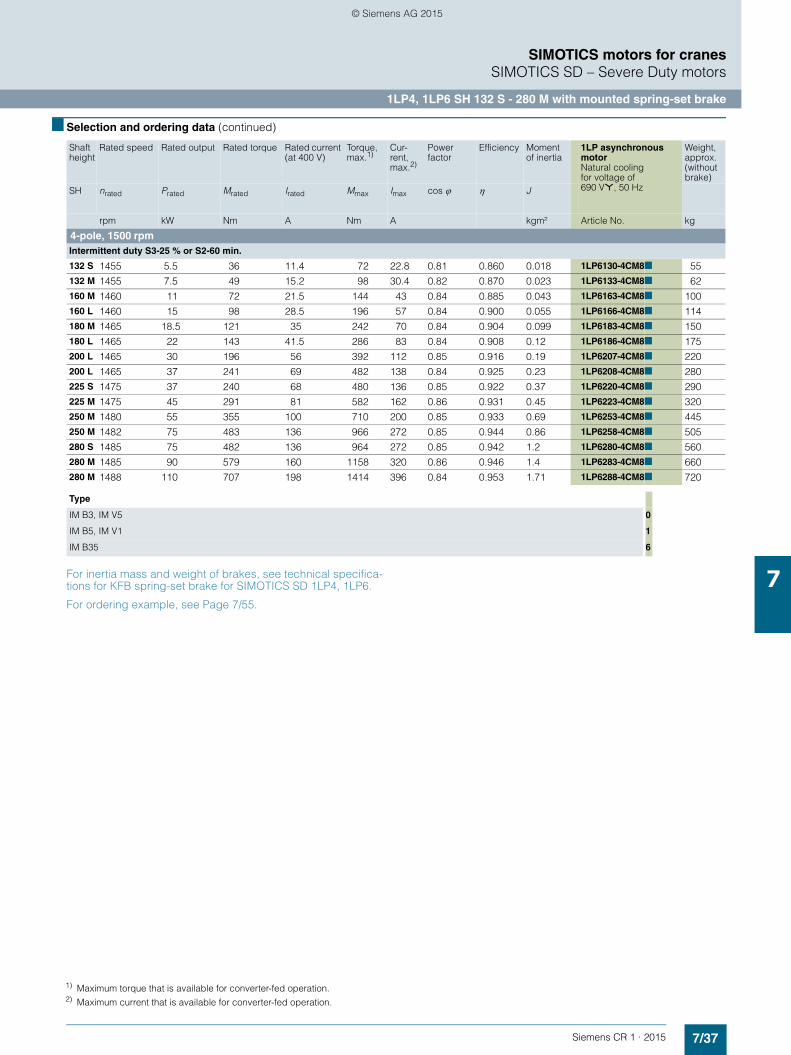
7/37Siemens CR 1 · 2015
7
■ Selection and ordering data (continued)
SIMOTICS motors for cranesSIMOTICS SD – Severe Duty motors
1LP4, 1LP6 SH 132 S - 280 M with mounted spring-set brake
For inertia mass and weight of brakes, see technical specifica-tions for KFB spring-set brake for SIMOTICS SD 1LP4, 1LP6.
For ordering example, see Page 7/55.
Shaft height
Rated speed Rated output Rated torque Rated current (at 400 V)
Torque,max.1)
Cur-rent, max.2)
Powerfactor
Efficiency Moment of inertia
1LP asynchronous motorNatural coolingfor voltage of690 V*, 50 Hz
Weight, approx.(without brake)
SH nrated Prated Mrated Irated Mmax Imax cos ϕ η J
rpm kW Nm A Nm A kgm² Article No. kg
4-pole, 1500 rpmIntermittent duty S3-25 % or S2-60 min.
132 S 1455 5.5 36 11.4 72 22.8 0.81 0.860 0.018 1LP6130-4CM8■ 55132 M 1455 7.5 49 15.2 98 30.4 0.82 0.870 0.023 1LP6133-4CM8■ 62160 M 1460 11 72 21.5 144 43 0.84 0.885 0.043 1LP6163-4CM8■ 100160 L 1460 15 98 28.5 196 57 0.84 0.900 0.055 1LP6166-4CM8■ 114180 M 1465 18.5 121 35 242 70 0.84 0.904 0.099 1LP6183-4CM8■ 150180 L 1465 22 143 41.5 286 83 0.84 0.908 0.12 1LP6186-4CM8■ 175200 L 1465 30 196 56 392 112 0.85 0.916 0.19 1LP6207-4CM8■ 220200 L 1465 37 241 69 482 138 0.84 0.925 0.23 1LP6208-4CM8■ 280225 S 1475 37 240 68 480 136 0.85 0.922 0.37 1LP6220-4CM8■ 290225 M 1475 45 291 81 582 162 0.86 0.931 0.45 1LP6223-4CM8■ 320250 M 1480 55 355 100 710 200 0.85 0.933 0.69 1LP6253-4CM8■ 445250 M 1482 75 483 136 966 272 0.85 0.944 0.86 1LP6258-4CM8■ 505280 S 1485 75 482 136 964 272 0.85 0.942 1.2 1LP6280-4CM8■ 560280 M 1485 90 579 160 1158 320 0.86 0.946 1.4 1LP6283-4CM8■ 660280 M 1488 110 707 198 1414 396 0.84 0.953 1.71 1LP6288-4CM8■ 720
Type
IM B3, IM V5 0
IM B5, IM V1 1
IM B35 6
1) Maximum torque that is available for converter-fed operation.2) Maximum current that is available for converter-fed operation.
© Siemens AG 2015

7/38 Siemens CR 1 · 2015
7
■ Selection and ordering data (continued)
SIMOTICS motors for cranesSIMOTICS SD – Severe Duty motors
1LP4, 1LP6 SH 132 S - 280 M with mounted spring-set brake
For inertia mass and weight of brakes, see technical specifica-tions for KFB spring-set brake for SIMOTICS SD 1LP4, 1LP6.
For ordering example, see Page 7/55.
Shaft height
Rated speed Rated output Rated torque Rated current (at 400 V)
Torque,max.1)
Cur-rent, max.2)
Power factor
Efficiency Moment of inertia
1LP asynchronous motorNatural cooling, for voltages of400 VΔ, 50 Hz460 VΔ, 50 Hz500 VΔ, 50 Hz
Weight, approx.(without brake)
SH nrated Prated Mrated Irated Mmax Imax cos ϕ η J
rpm kW Nm A Nm A kgm² Article No. kg
4-pole, 1500 rpmIntermittent duty S3-40 %
132 S 1462 4.4 28.7 10 72 22.8 0.75 0.860 0.018 1LP6130-4CA■■ 55132 M 1462 6 39.2 13.2 98 30.4 0.76 0.870 0.023 1LP6133-4CA■■ 62160 M 1470 8.8 57.2 18 144 43 0.79 0.885 0.043 1LP6163-4CA■■ 100160 L 1470 12 78 24.5 196 57 0.79 0.900 0.055 1LP6166-4CA■■ 114180 M 1472 14.8 96 30 242 70 0.78 0.908 0.099 1LP4183-4CA■■ 135180 L 1472 17.6 114 35 286 83 0.8 0.910 0.12 1LP4186-4CA■■ 150180 L 1472 24 156 52 392 118 0.74 0.915 0.14 1LP4188-4CA■■ 175200 L 1472 24 156 47 392 112 0.81 0.914 0.19 1LP4207-4CA■■ 195200 L 1472 29 188 59 482 138 0.77 0.923 0.23 1LP4208-4CA■■ 220200 L 1474 36 233 73 596 170 0.77 0.924 0.29 1LP4204-4CA■■ 280225 S 1480 29 187 57 480 136 0.8 0.923 0.37 1LP4220-4CA■■ 255225 M 1480 36 232 68 582 162 0.82 0.932 0.45 1LP4223-4CA■■ 290225 M 1480 44 284 82 712 198 0.83 0.935 0.49 1LP4228-4CA■■ 320250 M 1486 44 282 82 710 200 0.83 0.935 0.69 1LP4253-4CA■■ 375250 M 1487 60 385 113 966 272 0.81 0.946 0.86 1LP4258-4CA■■ 445250 M 1487 72 462 135 1160 324 0.81 0.946 0.98 1LP4254-4CA■■ 505280 S 1489 60 385 116 964 272 0.79 0.944 1.2 1LP4280-4CA■■ 515280 M 1489 72 462 131 1158 320 0.84 0.947 1.4 1LP4283-4CA■■ 560280 M 1490 88 564 168 1414 396 0.79 0.954 1.71 1LP4288-4CA■■ 660280 M 1489 105 673 208 1698 490 0.77 0.947 1.9 1LP4284-4CA■■ 720
Order code
Voltage
400 VΔ, 50 Hz 9 L5G
460 VΔ, 50 Hz 9 L5H
500 VΔ, 50 Hz 9 L5J
Type
IM B3, IM V5 0 −
IM B5, IM V1 1 −
IM B35 6 −
1) Maximum torque that is available for converter-fed operation.2) Maximum current that is available for converter-fed operation.
© Siemens AG 2015

7/39Siemens CR 1 · 2015
7
■ Selection and ordering data (continued)
SIMOTICS motors for cranesSIMOTICS SD – Severe Duty motors
1LP4, 1LP6 SH 132 S - 280 M with mounted spring-set brake
For inertia mass and weight of brakes, see technical specifica-tions for KFB spring-set brake for SIMOTICS SD 1LP4, 1LP6.
For ordering example, see Page 7/55.
Shaft height
Rated speed Rated output Rated torque Rated current (at 400 V)
Torque,max.1)
Cur-rent, max.2)
Power factor
Efficiency Moment of inertia
1LP asynchronous motorNatural coolingfor voltage of690 V*, 50 Hz
Weight, approx.(without brake)
SH nrated Prated Mrated Irated Mmax Imax cos ϕ η J
rpm kW Nm A Nm A kgm² Article No. kg
4-pole, 1500 rpmIntermittent duty S3-40 %
132 S 1462 4.4 28.7 10 72 22.8 0.75 0.860 0.018 1LP6130-4CM8■ 55132 M 1462 6 39.2 13.2 98 30.4 0.76 0.870 0.023 1LP6133-4CM8■ 62160 M 1470 8.8 57.2 18 144 43 0.79 0.885 0.043 1LP6163-4CM8■ 100160 L 1470 12 78 24.5 196 57 0.79 0.900 0.055 1LP6166-4CM8■ 114180 M 1472 14.8 96 30 242 70 0.78 0.908 0.099 1LP6183-4CM8■ 150180 L 1472 17.6 114 35 286 83 0.8 0.910 0.12 1LP6186-4CM8■ 175200 L 1472 24 156 47 392 112 0.81 0.914 0.19 1LP6207-4CM8■ 220200 L 1472 29 188 59 482 138 0.77 0.923 0.23 1LP6208-4CM8■ 280225 S 1480 29 187 57 480 136 0.8 0.923 0.37 1LP6220-4CM8■ 290225 M 1480 36 232 68 582 162 0.82 0.932 0.45 1LP6223-4CM8■ 320250 M 1486 44 282 82 710 200 0.83 0.935 0.69 1LP6253-4CM8■ 445250 M 1487 60 385 113 966 272 0.81 0.946 0.86 1LP6258-4CM8■ 505280 S 1489 60 385 116 964 272 0.79 0.944 1.2 1LP6280-4CM8■ 560280 M 1489 72 462 131 1158 320 0.84 0.947 1.4 1LP6283-4CM8■ 660280 M 1490 88 564 168 1414 396 0.79 0.954 1.71 1LP6288-4CM8■ 720
Type
IM B3, IM V5 0
IM B5, IM V1 1
IM B35 6
1) Maximum torque that is available for converter-fed operation.2) Maximum current that is available for converter-fed operation.
© Siemens AG 2015

7/40 Siemens CR 1 · 2015
7
■ Selection and ordering data (continued)
SIMOTICS motors for cranesSIMOTICS SD – Severe Duty motors
1LP4, 1LP6 SH 132 S - 280 M with mounted spring-set brake
For inertia mass and weight of brakes, see technical specifica-tions for KFB spring-set brake for SIMOTICS SD 1LP4, 1LP6.
For ordering example, see Page 7/55.
Shaft height
Rated speed Rated output Rated torque Rated current (at 400 V)
Torque,max.1)
Cur-rent, max.2)
Power factor
Efficiency Moment of inertia
1LP asynchronous motorNatural cooling, for voltages of400 VΔ, 50 Hz460 VΔ, 50 Hz500 VΔ, 50 Hz
Weight, approx.(without brake)
SH nrated Prated Mrated Irated Mmax Imax cos ϕ η J
rpm kW Nm A Nm A kgm² Article No. kg
4-pole, 1500 rpmIntermittent duty S3-60 %
132 S 1475 3.3 21.4 8.3 72 22.8 0.68 0.855 0.018 1LP6130-4CA■■ 55132 M 1475 4.5 29.1 11 98 30.4 0.69 0.865 0.023 1LP6133-4CA■■ 62160 M 1480 6.6 42.6 14.5 144 43 0.75 0.880 0.043 1LP6163-4CA■■ 100160 L 1480 9 58 20 196 57 0.73 0.895 0.055 1LP6166-4CA■■ 114180 M 1480 11.1 72 25.5 242 70 0.69 0.905 0.099 1LP4183-4CA■■ 135180 L 1480 13.2 85 29 286 83 0.73 0.900 0.12 1LP4186-4CA■■ 150180 L 1480 18 116 44 392 118 0.66 0.905 0.14 1LP4188-4CA■■ 175200 L 1480 18 116 39.5 392 112 0.73 0.904 0.19 1LP4207-4CA■■ 195200 L 1480 22 142 51 482 138 0.68 0.913 0.23 1LP4208-4CA■■ 220200 L 1481 27 174 63 596 170 0.68 0.914 0.29 1LP4204-4CA■■ 280225 S 1485 22 141 46 480 136 0.75 0.919 0.37 1LP4220-4CA■■ 255225 M 1485 27 174 54 582 162 0.78 0.928 0.45 1LP4223-4CA■■ 290225 M 1485 33 212 65 712 198 0.79 0.931 0.49 1LP4228-4CA■■ 320250 M 1490 33 211 67 710 200 0.76 0.931 0.69 1LP4253-4CA■■ 375250 M 1490 45 288 93 966 272 0.74 0.942 0.86 1LP4258-4CA■■ 445250 M 1490 54 346 111 1160 324 0.75 0.942 0.98 1LP4254-4CA■■ 505280 S 1492 45 288 93 964 272 0.74 0.942 1.2 1LP4280-4CA■■ 515280 M 1492 54 346 104 1158 320 0.79 0.944 1.4 1LP4283-4CA■■ 560280 M 1492 66 422 141 1414 396 0.71 0.950 1.71 1LP4288-4CA■■ 660280 M 1491 79 506 175 1698 490 0.69 0.945 1.9 1LP4284-4CA■■ 720
Order code
Voltage
400 VΔ, 50 Hz 9 L5G
460 VΔ, 50 Hz 9 L5H
500 VΔ, 50 Hz 9 L5J
Type
IM B3, IM V5 0 −
IM B5, IM V1 1 −
IM B35 6 −
1) Maximum torque that is available for converter-fed operation.2) Maximum current that is available for converter-fed operation.
© Siemens AG 2015

7/41Siemens CR 1 · 2015
7
■ Selection and ordering data (continued)
SIMOTICS motors for cranesSIMOTICS SD – Severe Duty motors
1LP4, 1LP6 SH 132 S - 280 M with mounted spring-set brake
For inertia mass and weight of brakes, see technical specifica-tions for KFB spring-set brake for SIMOTICS SD 1LP4, 1LP6.
For ordering example, see Page 7/55.
Shaft height
Rated speed Rated output Rated torque Rated current (at 400 V)
Torque,max.1)
Cur-rent, max.2)
Power factor
Efficiency Moment of inertia
1LP asynchronous motorNatural coolingfor voltage of690 V*, 50 Hz
Weight, approx.(without brake)
SH nrated Prated Mrated Irated Mmax Imax cos ϕ η J
rpm kW Nm A Nm A kgm² Article No. kg
4-pole, 1500 rpmIntermittent duty S3-60 %
132 S 1475 3.3 21.4 8.3 72 22.8 0.68 0.855 0.018 1LP6130-4CM8■ 55132 M 1475 4.5 29.1 11 98 30.4 0.69 0.865 0.023 1LP6133-4CM8■ 62160 M 1480 6.6 42.6 14.5 144 43 0.75 0.880 0.043 1LP6163-4CM8■ 100160 L 1480 9 58 20 196 57 0.73 0.895 0.055 1LP6166-4CM8■ 114180 M 1480 11.1 72 25.5 242 70 0.69 0.905 0.099 1LP6183-4CM8■ 150180 L 1480 13.2 85 29 286 83 0.73 0.900 0.12 1LP6186-4CM8■ 175200 L 1480 18 116 39.5 392 112 0.73 0.904 0.19 1LP6207-4CM8■ 220200 L 1480 22 142 51 482 138 0.68 0.913 0.23 1LP6208-4CM8■ 280225 S 1485 22 141 46 480 136 0.75 0.919 0.37 1LP6220-4CM8■ 290225 M 1485 27 174 54 582 162 0.78 0.928 0.45 1LP6223-4CM8■ 320250 M 1490 33 211 67 710 200 0.76 0.931 0.69 1LP6253-4CM8■ 445250 M 1490 45 288 93 966 272 0.74 0.942 0.86 1LP6258-4CM8■ 505280 S 1492 45 288 93 964 272 0.74 0.942 1.2 1LP6280-4CM8■ 560280 M 1492 54 346 104 1158 320 0.79 0.944 1.4 1LP6283-4CM8■ 660280 M 1492 66 422 141 1414 396 0.71 0.950 1.71 1LP6288-4CM8■ 720
Type
IM B3, IM V5 0
IM B5, IM V1 1
IM B35 6
1) Maximum torque that is available for converter-fed operation.2) Maximum current that is available for converter-fed operation.
© Siemens AG 2015
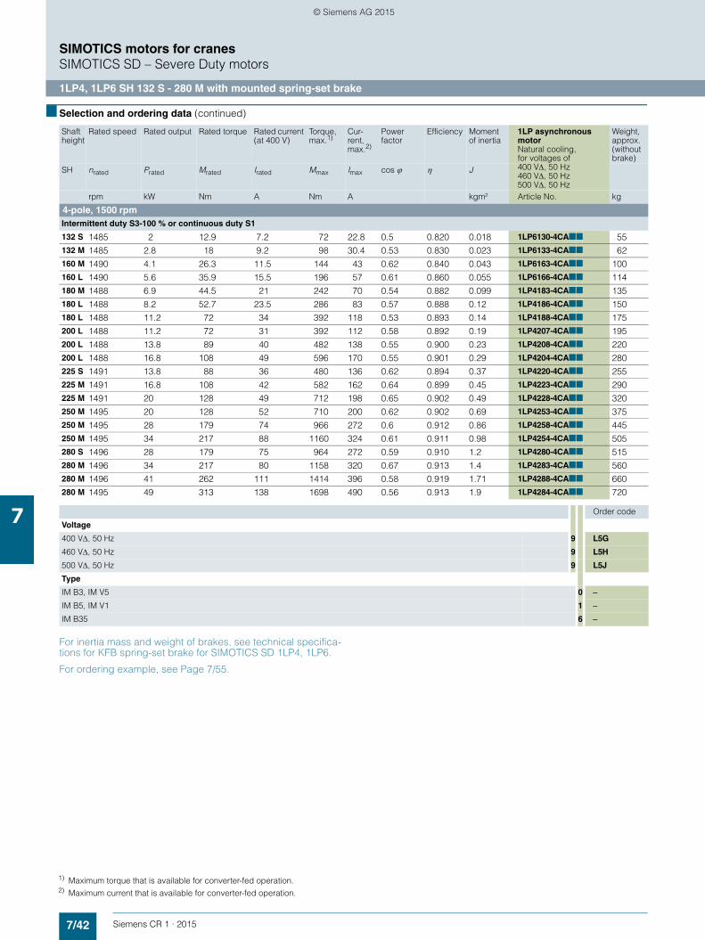
7/42 Siemens CR 1 · 2015
7
■ Selection and ordering data (continued)
SIMOTICS motors for cranesSIMOTICS SD – Severe Duty motors
1LP4, 1LP6 SH 132 S - 280 M with mounted spring-set brake
For inertia mass and weight of brakes, see technical specifica-tions for KFB spring-set brake for SIMOTICS SD 1LP4, 1LP6.
For ordering example, see Page 7/55.
Shaft height
Rated speed Rated output Rated torque Rated current (at 400 V)
Torque,max.1)
Cur-rent, max.2)
Power factor
Efficiency Moment of inertia
1LP asynchronous motorNatural cooling, for voltages of400 VΔ, 50 Hz460 VΔ, 50 Hz500 VΔ, 50 Hz
Weight, approx.(without brake)
SH nrated Prated Mrated Irated Mmax Imax cos ϕ η J
rpm kW Nm A Nm A kgm² Article No. kg
4-pole, 1500 rpmIntermittent duty S3-100 % or continuous duty S1
132 S 1485 2 12.9 7.2 72 22.8 0.5 0.820 0.018 1LP6130-4CA■■ 55132 M 1485 2.8 18 9.2 98 30.4 0.53 0.830 0.023 1LP6133-4CA■■ 62160 M 1490 4.1 26.3 11.5 144 43 0.62 0.840 0.043 1LP6163-4CA■■ 100160 L 1490 5.6 35.9 15.5 196 57 0.61 0.860 0.055 1LP6166-4CA■■ 114180 M 1488 6.9 44.5 21 242 70 0.54 0.882 0.099 1LP4183-4CA■■ 135180 L 1488 8.2 52.7 23.5 286 83 0.57 0.888 0.12 1LP4186-4CA■■ 150180 L 1488 11.2 72 34 392 118 0.53 0.893 0.14 1LP4188-4CA■■ 175200 L 1488 11.2 72 31 392 112 0.58 0.892 0.19 1LP4207-4CA■■ 195200 L 1488 13.8 89 40 482 138 0.55 0.900 0.23 1LP4208-4CA■■ 220200 L 1488 16.8 108 49 596 170 0.55 0.901 0.29 1LP4204-4CA■■ 280225 S 1491 13.8 88 36 480 136 0.62 0.894 0.37 1LP4220-4CA■■ 255225 M 1491 16.8 108 42 582 162 0.64 0.899 0.45 1LP4223-4CA■■ 290225 M 1491 20 128 49 712 198 0.65 0.902 0.49 1LP4228-4CA■■ 320250 M 1495 20 128 52 710 200 0.62 0.902 0.69 1LP4253-4CA■■ 375250 M 1495 28 179 74 966 272 0.6 0.912 0.86 1LP4258-4CA■■ 445250 M 1495 34 217 88 1160 324 0.61 0.911 0.98 1LP4254-4CA■■ 505280 S 1496 28 179 75 964 272 0.59 0.910 1.2 1LP4280-4CA■■ 515280 M 1496 34 217 80 1158 320 0.67 0.913 1.4 1LP4283-4CA■■ 560280 M 1496 41 262 111 1414 396 0.58 0.919 1.71 1LP4288-4CA■■ 660280 M 1495 49 313 138 1698 490 0.56 0.913 1.9 1LP4284-4CA■■ 720
Order code
Voltage
400 VΔ, 50 Hz 9 L5G
460 VΔ, 50 Hz 9 L5H
500 VΔ, 50 Hz 9 L5J
Type
IM B3, IM V5 0 −
IM B5, IM V1 1 −
IM B35 6 −
1) Maximum torque that is available for converter-fed operation.2) Maximum current that is available for converter-fed operation.
© Siemens AG 2015

7/43Siemens CR 1 · 2015
7
■ Selection and ordering data (continued)
SIMOTICS motors for cranesSIMOTICS SD – Severe Duty motors
1LP4, 1LP6 SH 132 S - 280 M with mounted spring-set brake
For inertia mass and weight of brakes, see technical specifica-tions for KFB spring-set brake for SIMOTICS SD 1LP4, 1LP6.
For ordering example, see Page 7/55.
Shaft height
Rated speed Rated output Rated torque Rated current (at 400 V)
Torque,max.1)
Cur-rent, max.2)
Power factor
Efficiency Moment of inertia
1LP asynchronous motorNatural coolingfor voltage of690 V*, 50 Hz
Weight, approx.(without brake)
SH nrated Prated Mrated Irated Mmax Imax cos ϕ η J
rpm kW Nm A Nm A kgm² Article No. kg
4-pole, 1500 rpmIntermittent duty S3-100 % or continuous duty S1
132 S 1485 2 12.9 7.2 72 22.8 0.5 0.820 0.018 1LP6130-4CM8■ 55132 M 1485 2.8 18 9.2 98 30.4 0.53 0.830 0.023 1LP6133-4CM8■ 62160 M 1490 4.1 26.3 11.5 144 43 0.62 0.840 0.043 1LP6163-4CM8■ 100160 L 1490 5.6 35.9 15.5 196 57 0.61 0.860 0.055 1LP6166-4CM8■ 114180 M 1488 6.9 44.5 21 242 70 0.54 0.882 0.099 1LP6183-4CM8■ 150180 L 1488 8.2 52.7 23.5 286 83 0.57 0.888 0.12 1LP6186-4CM8■ 175200 L 1488 11.2 72 31 392 112 0.58 0.892 0.19 1LP6207-4CM8■ 220200 L 1488 13.8 89 40 482 138 0.55 0.900 0.23 1LP6208-4CM8■ 280225 S 1491 13.8 88 36 480 136 0.62 0.894 0.37 1LP6220-4CM8■ 290225 M 1491 16.8 108 42 582 162 0.64 0.899 0.45 1LP6223-4CM8■ 320250 M 1495 20 128 52 710 200 0.62 0.902 0.69 1LP6253-4CM8■ 445250 M 1495 28 179 74 966 272 0.6 0.912 0.86 1LP6258-4CM8■ 505280 S 1496 28 179 75 964 272 0.59 0.910 1.2 1LP6280-4CM8■ 560280 M 1496 34 217 80 1158 320 0.67 0.913 1.4 1LP6283-4CM8■ 660280 M 1496 41 262 111 1414 396 0.58 0.919 1.71 1LP6288-4CM8■ 720
Type
IM B3, IM V5 0
IM B5, IM V1 1
IM B35 6
1) Maximum torque that is available for converter-fed operation.2) Maximum current that is available for converter-fed operation.
© Siemens AG 2015
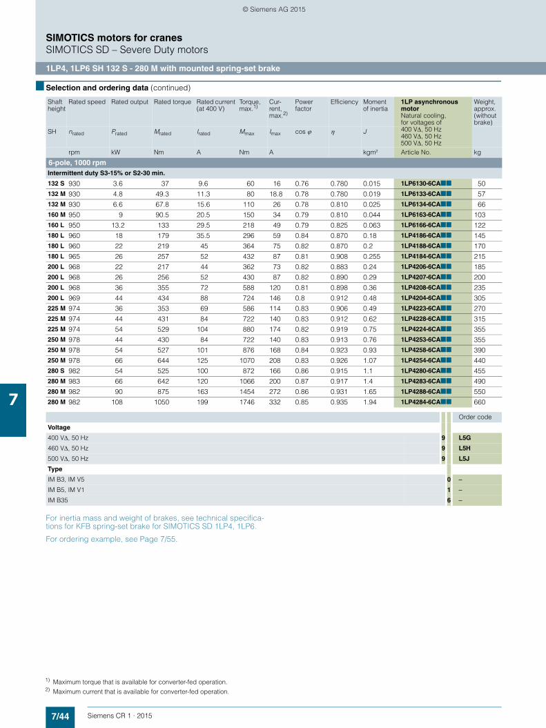
7/44 Siemens CR 1 · 2015
7
■ Selection and ordering data (continued)
SIMOTICS motors for cranesSIMOTICS SD – Severe Duty motors
1LP4, 1LP6 SH 132 S - 280 M with mounted spring-set brake
For inertia mass and weight of brakes, see technical specifica-tions for KFB spring-set brake for SIMOTICS SD 1LP4, 1LP6.
For ordering example, see Page 7/55.
Shaft height
Rated speed Rated output Rated torque Rated current (at 400 V)
Torque,max.1)
Cur-rent, max.2)
Power factor
Efficiency Moment of inertia
1LP asynchronous motorNatural cooling, for voltages of400 VΔ, 50 Hz460 VΔ, 50 Hz500 VΔ, 50 Hz
Weight, approx.(without brake)
SH nrated Prated Mrated Irated Mmax Imax cos ϕ η J
rpm kW Nm A Nm A kgm² Article No. kg
6-pole, 1000 rpmIntermittent duty S3-15% or S2-30 min.
132 S 930 3.6 37 9.6 60 16 0.76 0.780 0.015 1LP6130-6CA■■ 50132 M 930 4.8 49.3 11.3 80 18.8 0.78 0.780 0.019 1LP6133-6CA■■ 57132 M 930 6.6 67.8 15.6 110 26 0.78 0.810 0.025 1LP6134-6CA■■ 66160 M 950 9 90.5 20.5 150 34 0.79 0.810 0.044 1LP6163-6CA■■ 103160 L 950 13.2 133 29.5 218 49 0.79 0.825 0.063 1LP6166-6CA■■ 122180 L 960 18 179 35.5 296 59 0.84 0.870 0.18 1LP4186-6CA■■ 145180 L 960 22 219 45 364 75 0.82 0.870 0.2 1LP4188-6CA■■ 170180 L 965 26 257 52 432 87 0.81 0.908 0.255 1LP4184-6CA■■ 215200 L 968 22 217 44 362 73 0.82 0.883 0.24 1LP4206-6CA■■ 185200 L 968 26 256 52 430 87 0.82 0.890 0.29 1LP4207-6CA■■ 200200 L 968 36 355 72 588 120 0.81 0.898 0.36 1LP4208-6CA■■ 235200 L 969 44 434 88 724 146 0.8 0.912 0.48 1LP4204-6CA■■ 305225 M 974 36 353 69 586 114 0.83 0.906 0.49 1LP4223-6CA■■ 270225 M 974 44 431 84 722 140 0.83 0.912 0.62 1LP4228-6CA■■ 315225 M 974 54 529 104 880 174 0.82 0.919 0.75 1LP4224-6CA■■ 355250 M 978 44 430 84 722 140 0.83 0.913 0.76 1LP4253-6CA■■ 355250 M 978 54 527 101 876 168 0.84 0.923 0.93 1LP4258-6CA■■ 390250 M 978 66 644 125 1070 208 0.83 0.926 1.07 1LP4254-6CA■■ 440280 S 982 54 525 100 872 166 0.86 0.915 1.1 1LP4280-6CA■■ 455280 M 983 66 642 120 1066 200 0.87 0.917 1.4 1LP4283-6CA■■ 490280 M 982 90 875 163 1454 272 0.86 0.931 1.65 1LP4288-6CA■■ 550280 M 982 108 1050 199 1746 332 0.85 0.935 1.94 1LP4284-6CA■■ 660
Order code
Voltage
400 VΔ, 50 Hz 9 L5G
460 VΔ, 50 Hz 9 L5H
500 VΔ, 50 Hz 9 L5J
Type
IM B3, IM V5 0 −
IM B5, IM V1 1 −
IM B35 6 −
1) Maximum torque that is available for converter-fed operation.2) Maximum current that is available for converter-fed operation.
© Siemens AG 2015
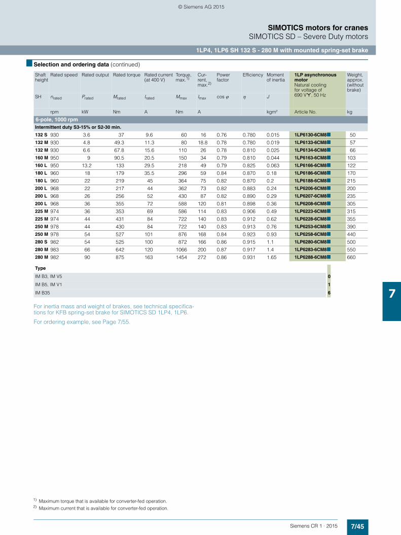
7/45Siemens CR 1 · 2015
7
■ Selection and ordering data (continued)
SIMOTICS motors for cranesSIMOTICS SD – Severe Duty motors
1LP4, 1LP6 SH 132 S - 280 M with mounted spring-set brake
For inertia mass and weight of brakes, see technical specifica-tions for KFB spring-set brake for SIMOTICS SD 1LP4, 1LP6.
For ordering example, see Page 7/55.
Shaft height
Rated speed Rated output Rated torque Rated current (at 400 V)
Torque,max.1)
Cur-rent, max.2)
Power factor
Efficiency Moment of inertia
1LP asynchronous motorNatural coolingfor voltage of690 V*, 50 Hz
Weight, approx.(without brake)
SH nrated Prated Mrated Irated Mmax Imax cos ϕ η J
rpm kW Nm A Nm A kgm² Article No. kg
6-pole, 1000 rpmIntermittent duty S3-15% or S2-30 min.
132 S 930 3.6 37 9.6 60 16 0.76 0.780 0.015 1LP6130-6CM8■ 50132 M 930 4.8 49.3 11.3 80 18.8 0.78 0.780 0.019 1LP6133-6CM8■ 57132 M 930 6.6 67.8 15.6 110 26 0.78 0.810 0.025 1LP6134-6CM8■ 66160 M 950 9 90.5 20.5 150 34 0.79 0.810 0.044 1LP6163-6CM8■ 103160 L 950 13.2 133 29.5 218 49 0.79 0.825 0.063 1LP6166-6CM8■ 122180 L 960 18 179 35.5 296 59 0.84 0.870 0.18 1LP6186-6CM8■ 170180 L 960 22 219 45 364 75 0.82 0.870 0.2 1LP6188-6CM8■ 215200 L 968 22 217 44 362 73 0.82 0.883 0.24 1LP6206-6CM8■ 200200 L 968 26 256 52 430 87 0.82 0.890 0.29 1LP6207-6CM8■ 235200 L 968 36 355 72 588 120 0.81 0.898 0.36 1LP6208-6CM8■ 305225 M 974 36 353 69 586 114 0.83 0.906 0.49 1LP6223-6CM8■ 315225 M 974 44 431 84 722 140 0.83 0.912 0.62 1LP6228-6CM8■ 355250 M 978 44 430 84 722 140 0.83 0.913 0.76 1LP6253-6CM8■ 390250 M 978 54 527 101 876 168 0.84 0.923 0.93 1LP6258-6CM8■ 440280 S 982 54 525 100 872 166 0.86 0.915 1.1 1LP6280-6CM8■ 500280 M 983 66 642 120 1066 200 0.87 0.917 1.4 1LP6283-6CM8■ 550280 M 982 90 875 163 1454 272 0.86 0.931 1.65 1LP6288-6CM8■ 660
Type
IM B3, IM V5 0
IM B5, IM V1 1
IM B35 6
1) Maximum torque that is available for converter-fed operation.2) Maximum current that is available for converter-fed operation.
© Siemens AG 2015

7/46 Siemens CR 1 · 2015
7
■ Selection and ordering data (continued)
SIMOTICS motors for cranesSIMOTICS SD – Severe Duty motors
1LP4, 1LP6 SH 132 S - 280 M with mounted spring-set brake
For inertia mass and weight of brakes, see technical specifica-tions for KFB spring-set brake for SIMOTICS SD 1LP4, 1LP6.
For ordering example, see Page 7/55.
Shaft height
Rated speed Rated output Rated torque Rated current (at 400 V)
Torque,max.1)
Cur-rent, max.2)
Power factor
Efficiency Moment of inertia
1LP asynchronous motorNatural cooling, for voltages of400 VΔ, 50 Hz460 VΔ, 50 Hz500 VΔ, 50 Hz
Weight, approx.(without brake)
SH nrated Prated Mrated Irated Mmax Imax cos ϕ η J
rpm kW Nm A Nm A kgm² Article No. kg
6-pole, 1000 rpmIntermittent duty S3-25 % or S2-60 min.
132 S 950 3 30 8 60 16 0.76 0.790 0.015 1LP6130-6CA■■ 50132 M 950 4 40 9.4 80 18.8 0.76 0.805 0.019 1LP6133-6CA■■ 57132 M 950 5.5 55 13 110 26 0.76 0.830 0.025 1LP6134-6CA■■ 66160 M 960 7.5 75 17 150 34 0.74 0.860 0.044 1LP6163-6CA■■ 103160 L 960 11 109 24.5 218 49 0.74 0.875 0.063 1LP6166-6CA■■ 122180 L 970 15 148 29.5 296 59 0.83 0.889 0.18 1LP4186-6CA■■ 145180 L 970 18.5 182 37.5 364 75 0.8 0.896 0.2 1LP4188-6CA■■ 170180 L 975 22 216 43.5 432 87 0.8 0.912 0.255 1LP4184-6CA■■ 215200 L 975 18.5 181 36.5 362 73 0.81 0.898 0.24 1LP4206-6CA■■ 185200 L 975 22 215 43.5 430 87 0.81 0.903 0.29 1LP4207-6CA■■ 200200 L 975 30 294 60 588 120 0.8 0.909 0.36 1LP4208-6CA■■ 235200 L 976 37 362 73 724 146 0.8 0.919 0.48 1LP4204-6CA■■ 305225 M 978 30 293 57 586 114 0.83 0.918 0.49 1LP4223-6CA■■ 270225 M 978 37 361 70 722 140 0.83 0.922 0.62 1LP4228-6CA■■ 315225 M 978 45 440 87 880 174 0.81 0.927 0.75 1LP4224-6CA■■ 355250 M 982 37 361 70 722 140 0.83 0.923 0.76 1LP4253-6CA■■ 355250 M 982 45 438 84 876 168 0.83 0.933 0.93 1LP4258-6CA■■ 390250 M 982 55 535 104 1070 208 0.81 0.934 1.07 1LP4254-6CA■■ 440280 S 985 45 436 83 872 166 0.85 0.924 1.1 1LP4280-6CA■■ 455280 M 985 55 533 100 1066 200 0.86 0.927 1.4 1LP4283-6CA■■ 490280 M 985 75 727 136 1454 272 0.84 0.938 1.65 1LP4288-6CA■■ 550280 M 985 90 873 166 1746 332 0.83 0.940 1.94 1LP4284-6CA■■ 660
Order code
Voltage
400 VΔ, 50 Hz 9 L5G
460 VΔ, 50 Hz 9 L5H
500 VΔ, 50 Hz 9 L5J
Type
IM B3, IM V5 0 −
IM B5, IM V1 1 −
IM B35 6 −
1) Maximum torque that is available for converter-fed operation.2) Maximum current that is available for converter-fed operation.
© Siemens AG 2015
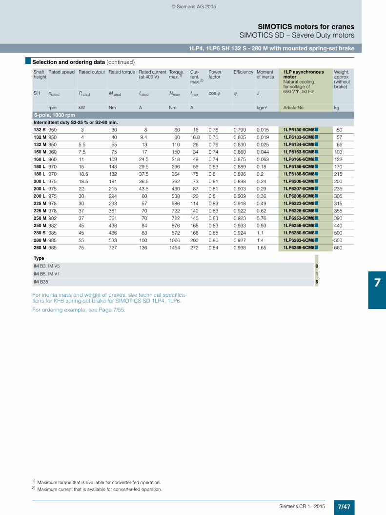
7/47Siemens CR 1 · 2015
7
■ Selection and ordering data (continued)
SIMOTICS motors for cranesSIMOTICS SD – Severe Duty motors
1LP4, 1LP6 SH 132 S - 280 M with mounted spring-set brake
For inertia mass and weight of brakes, see technical specifica-tions for KFB spring-set brake for SIMOTICS SD 1LP4, 1LP6.
For ordering example, see Page 7/55.
Shaft height
Rated speed Rated output Rated torque Rated current (at 400 V)
Torque,max.1)
Cur-rent, max.2)
Power factor
Efficiency Moment of inertia
1LP asynchronous motorNatural cooling,for voltage of690 V*, 50 Hz
Weight, approx.(without brake)
SH nrated Prated Mrated Irated Mmax Imax cos ϕ η J
rpm kW Nm A Nm A kgm² Article No. kg
6-pole, 1000 rpmIntermittent duty S3-25 % or S2-60 min.
132 S 950 3 30 8 60 16 0.76 0.790 0.015 1LP6130-6CM8■ 50132 M 950 4 40 9.4 80 18.8 0.76 0.805 0.019 1LP6133-6CM8■ 57132 M 950 5.5 55 13 110 26 0.76 0.830 0.025 1LP6134-6CM8■ 66160 M 960 7.5 75 17 150 34 0.74 0.860 0.044 1LP6163-6CM8■ 103160 L 960 11 109 24.5 218 49 0.74 0.875 0.063 1LP6166-6CM8■ 122180 L 970 15 148 29.5 296 59 0.83 0.889 0.18 1LP6186-6CM8■ 170180 L 970 18.5 182 37.5 364 75 0.8 0.896 0.2 1LP6188-6CM8■ 215200 L 975 18.5 181 36.5 362 73 0.81 0.898 0.24 1LP6206-6CM8■ 200200 L 975 22 215 43.5 430 87 0.81 0.903 0.29 1LP6207-6CM8■ 235200 L 975 30 294 60 588 120 0.8 0.909 0.36 1LP6208-6CM8■ 305225 M 978 30 293 57 586 114 0.83 0.918 0.49 1LP6223-6CM8■ 315225 M 978 37 361 70 722 140 0.83 0.922 0.62 1LP6228-6CM8■ 355250 M 982 37 361 70 722 140 0.83 0.923 0.76 1LP6253-6CM8■ 390250 M 982 45 438 84 876 168 0.83 0.933 0.93 1LP6258-6CM8■ 440280 S 985 45 436 83 872 166 0.85 0.924 1.1 1LP6280-6CM8■ 500280 M 985 55 533 100 1066 200 0.86 0.927 1.4 1LP6283-6CM8■ 550280 M 985 75 727 136 1454 272 0.84 0.938 1.65 1LP6288-6CM8■ 660
Type
IM B3, IM V5 0
IM B5, IM V1 1
IM B35 6
1) Maximum torque that is available for converter-fed operation.2) Maximum current that is available for converter-fed operation.
© Siemens AG 2015

7/48 Siemens CR 1 · 2015
7
■ Selection and ordering data (continued)
SIMOTICS motors for cranesSIMOTICS SD – Severe Duty motors
1LP4, 1LP6 SH 132 S - 280 M with mounted spring-set brake
For inertia mass and weight of brakes, see technical specifica-tions for KFB spring-set brake for SIMOTICS SD 1LP4, 1LP6.
For ordering example, see Page 7/55.
Shaft height
Rated speed Rated output Rated torque Rated current (at 400 V)
Torque,max.1)
Cur-rent, max.2)
Power factor
Efficiency Moment of inertia
1LP asynchronous motorNatural cooling, for voltages of400 VΔ, 50 Hz460 VΔ, 50 Hz500 VΔ, 50 Hz
Weight, approx.(without brake)
SH nrated Prated Mrated Irated Mmax Imax cos ϕ η J
rpm kW Nm A Nm A kgm² Article No. kg
6-pole, 1000 rpmIntermittent duty S3-40 %
132 S 960 2.4 23.9 7 60 16 0.65 0.800 0.015 1LP6130-6CA■■ 50132 M 960 3.2 31.8 8.3 80 18.8 0.72 0.780 0.019 1LP6133-6CA■■ 57132 M 960 4.4 43.8 11.4 110 26 0.68 0.840 0.025 1LP6134-6CA■■ 66160 M 970 6 59 15.5 150 34 0.66 0.860 0.044 1LP6163-6CA■■ 103160 L 970 8.8 86.5 22 218 49 0.67 0.880 0.063 1LP6166-6CA■■ 122180 L 981 12 118 24 296 59 0.81 0.895 0.18 1LP4186-6CA■■ 145180 L 981 14.8 144 32 364 75 0.77 0.873 0.2 1LP4188-6CA■■ 170180 L 984 17.6 171 37 432 87 0.76 0.920 0.255 1LP4184-6CA■■ 215200 L 980 14.8 144 31.5 362 73 0.76 0.899 0.24 1LP4206-6CA■■ 185200 L 980 17.6 172 36.5 430 87 0.77 0.905 0.29 1LP4207-6CA■■ 200200 L 980 24 234 52 588 120 0.75 0.910 0.36 1LP4208-6CA■■ 235200 L 981 29 282 63 724 146 0.74 0.920 0.48 1LP4204-6CA■■ 305225 M 984 24 233 46 586 114 0.82 0.920 0.49 1LP4223-6CA■■ 270225 M 984 29 281 56 722 140 0.81 0.926 0.62 1LP4228-6CA■■ 315225 M 984 36 349 70 880 174 0.8 0.929 0.75 1LP4224-6CA■■ 355250 M 986 29 281 58 722 140 0.78 0.928 0.76 1LP4253-6CA■■ 355250 M 986 36 349 70 876 168 0.8 0.938 0.93 1LP4258-6CA■■ 390250 M 986 44 426 86 1070 208 0.79 0.937 1.07 1LP4254-6CA■■ 440280 S 989 36 348 71 872 166 0.79 0.931 1.1 1LP4280-6CA■■ 455280 M 989 44 425 85 1066 200 0.81 0.932 1.4 1LP4283-6CA■■ 490280 M 989 60 579 116 1454 272 0.8 0.943 1.65 1LP4288-6CA■■ 550280 M 989 72 695 141 1746 332 0.79 0.945 1.94 1LP4284-6CA■■ 660
Order code
Voltage
400 VΔ, 50 Hz 9 L5G
460 VΔ, 50 Hz 9 L5H
500 VΔ, 50 Hz 9 L5J
Type
IM B3, IM V5 0 −
IM B5, IM V1 1 −
IM B35 6 −
1) Maximum torque that is available for converter-fed operation.2) Maximum current that is available for converter-fed operation.
© Siemens AG 2015

7/49Siemens CR 1 · 2015
7
■ Selection and ordering data (continued)
SIMOTICS motors for cranesSIMOTICS SD – Severe Duty motors
1LP4, 1LP6 SH 132 S - 280 M with mounted spring-set brake
For inertia mass and weight of brakes, see technical specifica-tions for KFB spring-set brake for SIMOTICS SD 1LP4, 1LP6.
For ordering example, see Page 7/55.
Shaft height
Rated speed Rated output Rated torque Rated current (at 400 V)
Torque,max.1)
Cur-rent, max.2)
Power factor
Efficiency Moment of inertia
1LP asynchronous motorNatural coolingfor voltage of690 V*, 50 Hz
Weight, approx.(without brake)
SH nrated Prated Mrated Irated Mmax Imax cos ϕ η J
rpm kW Nm A Nm A kgm² Article No. kg
6-pole, 1000 rpmIntermittent duty S3-40 %
132 S 960 2.4 23.9 7 60 16 0.65 0.800 0.015 1LP6130-6CM8■ 50132 M 960 3.2 31.8 8.3 80 18.8 0.72 0.780 0.019 1LP6133-6CM8■ 57132 M 960 4.4 43.8 11.4 110 26 0.68 0.840 0.025 1LP6134-6CM8■ 66160 M 970 6 59 15.5 150 34 0.66 0.860 0.044 1LP6163-6CM8■ 103160 L 970 8.8 86.5 22 218 49 0.67 0.880 0.063 1LP6166-6CM8■ 122180 L 981 12 118 24 296 59 0.81 0.895 0.18 1LP6186-6CM8■ 170180 L 981 14.8 144 32 364 75 0.77 0.873 0.2 1LP6188-6CM8■ 215200 L 980 14.8 144 31.5 362 73 0.76 0.899 0.24 1LP6206-6CM8■ 200200 L 980 17.6 172 36.5 430 87 0.77 0.905 0.29 1LP6207-6CM8■ 235200 L 980 24 234 52 588 120 0.75 0.910 0.36 1LP6208-6CM8■ 305225 M 984 24 233 46 586 114 0.82 0.920 0.49 1LP6223-6CM8■ 315225 M 984 29 281 56 722 140 0.81 0.926 0.62 1LP6228-6CM8■ 355250 M 986 29 281 58 722 140 0.78 0.928 0.76 1LP6253-6CM8■ 390250 M 986 36 349 70 876 168 0.8 0.938 0.93 1LP6258-6CM8■ 440280 S 989 36 348 71 872 166 0.79 0.931 1.1 1LP6280-6CM8■ 500280 M 989 44 425 85 1066 200 0.81 0.932 1.4 1LP6283-6CM8■ 550280 M 989 60 579 116 1454 272 0.8 0.943 1.65 1LP6288-6CM8■ 660
Type
IM B3, IM V5 0
IM B5, IM V1 1
IM B35 6
1) Maximum torque that is available for converter-fed operation.2) Maximum current that is available for converter-fed operation.
© Siemens AG 2015

7/50 Siemens CR 1 · 2015
7
■ Selection and ordering data (continued)
SIMOTICS motors for cranesSIMOTICS SD – Severe Duty motors
1LP4, 1LP6 SH 132 S - 280 M with mounted spring-set brake
For inertia mass and weight of brakes, see technical specifica-tions for KFB spring-set brake for SIMOTICS SD 1LP4, 1LP6.
For ordering example, see Page 7/55.
Shaft height
Rated speed Rated output Rated torque Rated current (at 400 V)
Torque,max.1)
Cur-rent, max.2)
Power factor
Efficiency Moment of inertia
1LP asynchronous motorNatural cooling, for voltages of400 VΔ, 50 Hz460 VΔ, 50 Hz500 VΔ, 50 Hz
Weight, approx.(without brake)
SH nrated Prated Mrated Irated Mmax Imax cos ϕ η J
rpm kW Nm A Nm A kgm² Article No. kg
6-pole, 1000 rpmIntermittent duty S3-60 %
132 S 975 1.8 17.6 6.3 60 16 0.55 0.800 0.015 1LP6130-6CA■■ 50132 M 975 2.4 23.5 7.3 80 18.8 0.62 0.770 0.019 1LP6133-6CA■■ 57132 M 975 3.3 32.3 9.8 110 26 0.62 0.810 0.025 1LP6134-6CA■■ 66160 M 980 4.5 44 13 150 34 0.6 0.850 0.044 1LP6163-6CA■■ 103160 L 980 6.6 64.3 18.8 218 49 0.59 0.880 0.063 1LP6166-6CA■■ 122180 L 984 9 88 20 296 59 0.73 0.896 0.18 1LP4186-6CA■■ 145180 L 984 11.1 108 26 364 75 0.7 0.870 0.2 1LP4188-6CA■■ 170180 L 986 13.2 128 30 432 87 0.7 0.915 0.255 1LP4184-6CA■■ 215200 L 986 11.1 108 26 362 73 0.7 0.897 0.24 1LP4206-6CA■■ 185200 L 986 13.2 128 29 430 87 0.73 0.904 0.29 1LP4207-6CA■■ 200200 L 986 18 174 43 588 120 0.68 0.905 0.36 1LP4208-6CA■■ 235200 L 986 22 213 52 724 146 0.67 0.914 0.48 1LP4204-6CA■■ 305225 M 988 18 174 37 586 114 0.77 0.922 0.49 1LP4223-6CA■■ 270225 M 988 22 213 46 722 140 0.75 0.925 0.62 1LP4228-6CA■■ 315225 M 988 27 261 57 880 174 0.74 0.925 0.75 1LP4224-6CA■■ 355250 M 990 22 212 47 722 140 0.73 0.926 0.76 1LP4253-6CA■■ 355250 M 990 27 260 57 876 168 0.74 0.936 0.93 1LP4258-6CA■■ 390250 M 990 33 318 70 1070 208 0.73 0.933 1.07 1LP4254-6CA■■ 440280 S 992 27 260 56 872 166 0.76 0.925 1.1 1LP4280-6CA■■ 455280 M 992 33 318 68 1066 200 0.75 0.934 1.4 1LP4283-6CA■■ 490280 M 992 45 433 92 1454 272 0.76 0.940 1.65 1LP4288-6CA■■ 550280 M 992 54 520 113 1746 332 0.74 0.946 1.94 1LP4284-6CA■■ 660
Order code
Voltage
400 VΔ, 50 Hz 9 L5G
460 VΔ, 50 Hz 9 L5H
500 VΔ, 50 Hz 9 L5J
Type
IM B3, IM V5 0 −
IM B5, IM V1 1 −
IM B35 6 −
1) Maximum torque that is available for converter-fed operation.2) Maximum current that is available for converter-fed operation.
© Siemens AG 2015

7/51Siemens CR 1 · 2015
7
■ Selection and ordering data (continued)
SIMOTICS motors for cranesSIMOTICS SD – Severe Duty motors
1LP4, 1LP6 SH 132 S - 280 M with mounted spring-set brake
For inertia mass and weight of brakes, see technical specifica-tions for KFB spring-set brake for SIMOTICS SD 1LP4, 1LP6.
For ordering example, see Page 7/55.
Shaft height
Rated speed Rated output Rated torque Rated current (at 400 V)
Torque,max.1)
Cur-rent, max.2)
Power factor
Efficiency Moment of inertia
1LP asynchronous motorNatural coolingfor voltage of690 V*, 50 Hz
Weight, approx.(without brake)
SH nrated Prated Mrated Irated Mmax Imax cos ϕ η J
rpm kW Nm A Nm A kgm² Article No. kg
6-pole, 1000 rpmIntermittent duty S3-60 %
132 S 975 1.8 17.6 6.3 60 16 0.55 0.800 0.015 1LP6130-6CM8■ 50132 M 975 2.4 23.5 7.3 80 18.8 0.62 0.770 0.019 1LP6133-6CM8■ 57132 M 975 3.3 32.3 9.8 110 26 0.62 0.810 0.025 1LP6134-6CM8■ 66160 M 980 4.5 44 13 150 34 0.6 0.850 0.044 1LP6163-6CM8■ 103160 L 980 6.6 64.3 18.8 218 49 0.59 0.880 0.063 1LP6166-6CM8■ 122180 L 984 9 88 20 296 59 0.73 0.896 0.18 1LP6186-6CM8■ 170180 L 984 11.1 108 26 364 75 0.7 0.870 0.2 1LP6188-6CM8■ 215200 L 986 11.1 108 26 362 73 0.7 0.897 0.24 1LP6206-6CM8■ 200200 L 986 13.2 128 29 430 87 0.73 0.904 0.29 1LP6207-6CM8■ 235200 L 986 18 174 43 588 120 0.68 0.905 0.36 1LP6208-6CM8■ 305225 M 988 18 174 37 586 114 0.77 0.922 0.49 1LP6223-6CM8■ 315225 M 988 22 213 46 722 140 0.75 0.925 0.62 1LP6228-6CM8■ 355250 M 990 22 212 47 722 140 0.73 0.926 0.76 1LP6253-6CM8■ 390250 M 990 27 260 57 876 168 0.74 0.936 0.93 1LP6258-6CM8■ 440280 S 992 27 260 56 872 166 0.76 0.925 1.1 1LP6280-6CM8■ 500280 M 992 33 318 68 1066 200 0.75 0.934 1.4 1LP6283-6CM8■ 550280 M 992 45 433 92 1454 272 0.76 0.940 1.65 1LP6288-6CM8■ 660
Type
IM B3, IM V5 0
IM B5, IM V1 1
IM B35 6
1) Maximum torque that is available for converter-fed operation.2) Maximum current that is available for converter-fed operation.
© Siemens AG 2015

7/52 Siemens CR 1 · 2015
7
■ Selection and ordering data (continued)
SIMOTICS motors for cranesSIMOTICS SD – Severe Duty motors
1LP4, 1LP6 SH 132 S - 280 M with mounted spring-set brake
For inertia mass and weight of brakes, see technical specifica-tions for KFB spring-set brake for SIMOTICS SD 1LP4, 1LP6.
For ordering example, see Page 7/55.
Shaft height
Rated speed Rated output Rated torque Rated current (at 400 V)
Torque,max.1)
Cur-rent, max.2)
Power factor
Efficiency Moment of inertia
1LP asynchronous motorNatural cooling, for voltages of400 VΔ, 50 Hz460 VΔ, 50 Hz500 VΔ, 50 Hz
Weight, approx.(without brake)
SH nrated Prated Mrated Irated Mmax Imax cos ϕ η J
rpm kW Nm A Nm A kgm² Article No. kg
6-pole, 1000 rpmIntermittent duty S3-100 % or continuous duty S1
132 S 988 1.1 10.6 5.7 60 16 0.45 0.680 0.015 1LP6130-6CA■■ 50132 M 988 1.5 14.5 6.4 80 18.8 0.48 0.720 0.019 1LP6133-6CA■■ 57132 M 988 2 19.3 8.5 110 26 0.46 0.780 0.025 1LP6134-6CA■■ 66160 M 988 2.8 27 11 150 34 0.46 0.820 0.044 1LP6163-6CA■■ 103160 L 988 4.1 39.6 15.5 218 49 0.46 0.850 0.063 1LP6166-6CA■■ 122180 L 990 5.6 54 16 296 59 0.62 0.820 0.18 1LP4186-6CA■■ 145180 L 990 6.9 67 21 364 75 0.56 0.850 0.2 1LP4188-6CA■■ 170180 L 991 8.2 79 24.5 432 87 0.58 0.880 0.255 1LP4184-6CA■■ 215200 L 991 6.9 66.5 20 362 73 0.58 0.870 0.24 1LP4206-6CA■■ 185200 L 991 8.2 79 23 430 87 0.59 0.880 0.29 1LP4207-6CA■■ 200200 L 991 11.2 108 34 588 120 0.55 0.880 0.36 1LP4208-6CA■■ 235200 L 991 13.8 133 41 724 146 0.54 0.900 0.48 1LP4204-6CA■■ 305225 M 993 11.2 108 28.5 586 114 0.63 0.908 0.49 1LP4223-6CA■■ 270225 M 993 13.8 133 35 722 140 0.63 0.910 0.62 1LP4228-6CA■■ 315225 M 993 16.8 162 43.5 880 174 0.62 0.907 0.75 1LP4224-6CA■■ 355250 M 994 13.8 133 35 722 140 0.63 0.915 0.76 1LP4253-6CA■■ 355250 M 994 16.8 161 42 876 168 0.63 0.920 0.93 1LP4258-6CA■■ 390250 M 994 20 192 52 1070 208 0.61 0.925 1.07 1LP4254-6CA■■ 440280 S 995 16.8 161 43 872 166 0.62 0.914 1.1 1LP4280-6CA■■ 455280 M 995 20 192 52 1066 200 0.61 0.920 1.4 1LP4283-6CA■■ 490280 M 995 28 269 71 1454 272 0.63 0.916 1.65 1LP4288-6CA■■ 550280 M 995 34 326 86 1746 332 0.62 0.930 1.94 1LP4284-6CA■■ 660
Order code
Voltage
400 VΔ, 50 Hz 9 L5G
460 VΔ, 50 Hz 9 L5H
500 VΔ, 50 Hz 9 L5J
Type
IM B3, IM V5 0 −
IM B5, IM V1 1 −
IM B35 6 −
1) Maximum torque that is available for converter-fed operation.2) Maximum current that is available for converter-fed operation.
© Siemens AG 2015

7/53Siemens CR 1 · 2015
7
■ Selection and ordering data (continued)
SIMOTICS motors for cranesSIMOTICS SD – Severe Duty motors
1LP4, 1LP6 SH 132 S - 280 M with mounted spring-set brake
For inertia mass and weight of brakes, see technical specifica-tions for KFB spring-set brake for SIMOTICS SD 1LP4, 1LP6.
For ordering example, see Page 7/55.
Shaft height
Rated speed Rated output Rated torque Rated current (at 400 V)
Torque,max.1)
Cur-rent, max.2)
Power factor
Efficiency Moment of inertia
1LP asynchronous motorNatural coolingfor voltage of690 V*, 50 Hz
Weight, approx.(without brake)
SH nrated Prated Mrated Irated Mmax Imax cos ϕ η J
rpm kW Nm A Nm A kgm² Article No. kg
6-pole, 1000 rpmIntermittent duty S3-100 % or continuous duty S1
132 S 988 1.1 10.6 5.7 60 16 0.45 0.680 0.015 1LP6130-6CM8■ 50132 M 988 1.5 14.5 6.4 80 18.8 0.48 0.720 0.019 1LP6133-6CM8■ 57132 M 988 2 19.3 8.5 110 26 0.46 0.780 0.025 1LP6134-6CM8■ 66160 M 988 2.8 27 11 150 34 0.46 0.820 0.044 1LP6163-6CM8■ 103160 L 988 4.1 39.6 15.5 218 49 0.46 0.850 0.063 1LP6166-6CM8■ 122180 L 990 5.6 54 16 296 59 0.62 0.820 0.18 1LP6186-6CM8■ 170180 L 990 6.9 67 21 364 75 0.56 0.850 0.2 1LP6188-6CM8■ 215200 L 991 6.9 66.5 20 362 73 0.58 0.870 0.24 1LP6206-6CM8■ 200200 L 991 8.2 79 23 430 87 0.59 0.880 0.29 1LP6207-6CM8■ 235200 L 991 11.2 108 34 588 120 0.55 0.880 0.36 1LP6208-6CM8■ 305225 M 993 11.2 108 28.5 586 114 0.63 0.908 0.49 1LP6223-6CM8■ 315225 M 993 13.8 133 35 722 140 0.63 0.910 0.62 1LP6228-6CM8■ 355250 M 994 13.8 133 35 722 140 0.63 0.915 0.76 1LP6253-6CM8■ 390250 M 994 16.8 161 42 876 168 0.63 0.920 0.93 1LP6258-6CM8■ 440280 S 995 16.8 161 43 872 166 0.62 0.914 1.1 1LP6280-6CM8■ 500280 M 995 20 192 52 1066 200 0.61 0.920 1.4 1LP6283-6CM8■ 550280 M 995 28 269 71 1454 272 0.63 0.916 1.65 1LP6288-6CM8■ 660
Type
IM B3, IM V5 0
IM B5, IM V1 1
IM B35 6
1) Maximum torque that is available for converter-fed operation.2) Maximum current that is available for converter-fed operation.
© Siemens AG 2015
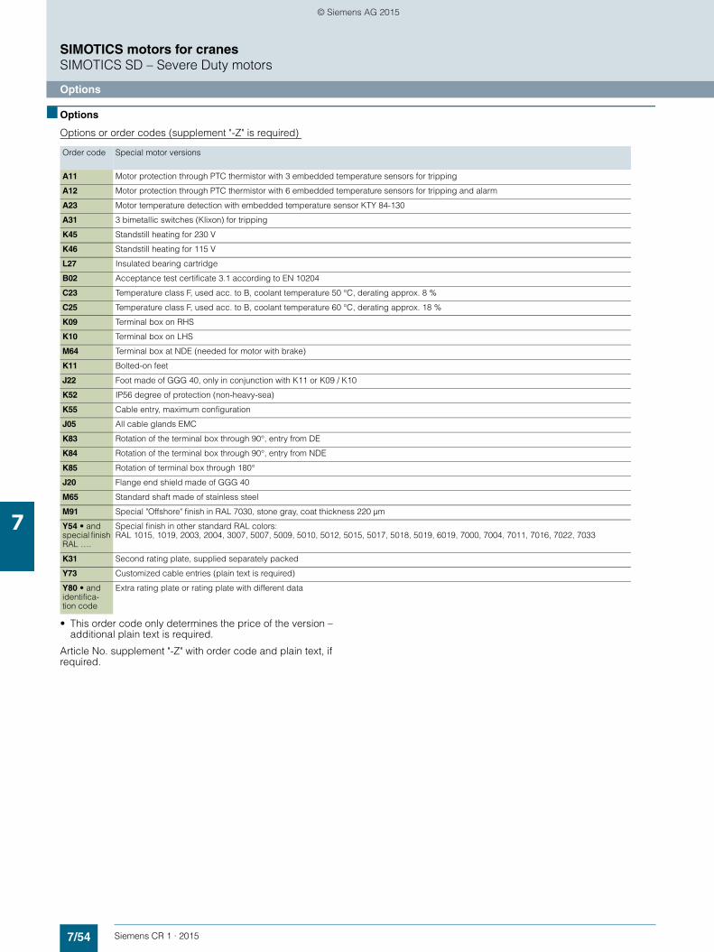
7/54 Siemens CR 1 · 2015
7
SIMOTICS motors for cranesSIMOTICS SD – Severe Duty motors
Options
■ Options
Options or order codes (supplement "-Z" is required)
• This order code only determines the price of the version – additional plain text is required.
Article No. supplement "-Z" with order code and plain text, if required.
Order code Special motor versions
A11 Motor protection through PTC thermistor with 3 embedded temperature sensors for tripping
A12 Motor protection through PTC thermistor with 6 embedded temperature sensors for tripping and alarm
A23 Motor temperature detection with embedded temperature sensor KTY 84-130
A31 3 bimetallic switches (Klixon) for tripping
K45 Standstill heating for 230 V
K46 Standstill heating for 115 V
L27 Insulated bearing cartridge
B02 Acceptance test certificate 3.1 according to EN 10204
C23 Temperature class F, used acc. to B, coolant temperature 50 °C, derating approx. 8 %
C25 Temperature class F, used acc. to B, coolant temperature 60 °C, derating approx. 18 %
K09 Terminal box on RHS
K10 Terminal box on LHS
M64 Terminal box at NDE (needed for motor with brake)
K11 Bolted-on feet
J22 Foot made of GGG 40, only in conjunction with K11 or K09 / K10
K52 IP56 degree of protection (non-heavy-sea)
K55 Cable entry, maximum configuration
J05 All cable glands EMC
K83 Rotation of the terminal box through 90°, entry from DE
K84 Rotation of the terminal box through 90°, entry from NDE
K85 Rotation of terminal box through 180°
J20 Flange end shield made of GGG 40
M65 Standard shaft made of stainless steel
M91 Special "Offshore" finish in RAL 7030, stone gray, coat thickness 220 µm
Y54 • andspecial finish RAL ….
Special finish in other standard RAL colors: RAL 1015, 1019, 2003, 2004, 3007, 5007, 5009, 5010, 5012, 5015, 5017, 5018, 5019, 6019, 7000, 7004, 7011, 7016, 7022, 7033
K31 Second rating plate, supplied separately packed
Y73 Customized cable entries (plain text is required)
Y80 • and identifica-tion code
Extra rating plate or rating plate with different data
© Siemens AG 2015

7/55Siemens CR 1 · 2015
7
■ Options (continued)
SIMOTICS motors for cranesSIMOTICS SD – Severe Duty motors
Options
Non-standard brake coil voltage on request.
Ordering example
Order code Special brake versions
J18 Mounting of pulse encoder POG 10 DN 1024 I on the brake (possible only in conjunction with J28, option includes the encoder)
J30 Mounting of brake KFB 10
J31 Mounting of brake KFB 16
J32 Mounting of brake KFB 25
J33 Mounting of brake KFB 30
J34 Mounting of brake KFB 40
J35 Mounting of brake KFB 63
J36 Mounting of brake KFB 100
J37 Mounting of brake KFB 160
C01 Brake supply voltage 400 V AC (equivalent to DC = 180 V) with half-wave rectifier in the terminal box
J25 Hand lever release for brake
J26 Microswitch "brake released"
J24 Microswitch "air-gap monitoring"
J27 230 V brake standstill heating
J28 Brake with components for mounting encoder POG 10 (T2)
J29 Brake prepared for mounting encoder POG 10 (T1)
G80 Mounting of rotary pulse encoder POG 10 DN 1024 I on motor without fan (without fitted brake)
C07 Brake supply voltage 230 V AC (equivalent to DC = 207 V) with bridge rectifier in the terminal box
Selection criteria Requirement Structure of the Article No.
Motor type Brake motor without external fan, degree of protection IP55, gray cast-iron model
1LP4■■■-■■■■■
Shaft height 180 M 1LP4183-■■■■■
No. of poles/speed 4-pole 1LP4183-4■■■■
Version Crane version 1LP4183-4CA■■
Voltage/frequency 400 VΔ, 50 Hz 1LP4183-4CA9■L5G
Type of construction IM B5 1LP4183-4CA91 L5G
Special versionMotor protection through PTC thermistor with 6 embedded temperature sensors for tripping and alarm
1LP4183-4CA91-Z L5G+A12
Standstill heating for 230 V 1LP4183-4CA91-Z L5G+A12+K45
Mounting of brake KFB 25 1LP4183-4CA91-Z L5G+A12+K45+J32
Hand lever release for brake 1LP4183-4CA91-Z L5G+A12+K45+J32+J25
Microswitch "brake released" 1LP4183-4CA91-Z L5G+A12+K45+J32+J25+J26
230 V brake standstill heating 1LP4183-4CA91-Z L5G+A12+K45+J32+J25+J26+J27
Brake with components for mounting encoder POG 10 (T2)
1LP4183-4CA91-Z L5G+A12+K45+J32+J25+J26+J27+J28
Complete ordering information for required version of brake motor 1LP4183-4CA91-Z L5G+A12+K45+J32+J25+J26+J27+J28
© Siemens AG 2015
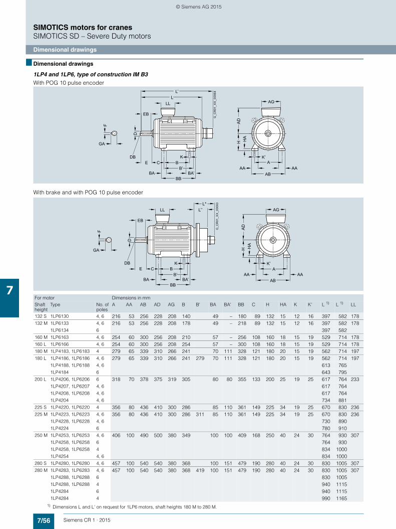
7/56 Siemens CR 1 · 2015
7
SIMOTICS motors for cranesSIMOTICS SD – Severe Duty motors
Dimensional drawings
■ Dimensional drawings
1LP4 and 1LP6, type of construction IM B3With POG 10 pulse encoder
With brake and with POG 10 pulse encoder
HA
HA
D
AAA
K’
AAAB
AG
E C BB’
K
BBBA BA’
LL
EB
LF
GA
D
L’
G_C
R01
_XX
_000
64
DB
For motor Dimensions in mmShaftheight
Type No. ofpoles
A AA AB AD AG B B' BA BA' BB C H HA K K' L 1) L 1) LL
132 S 1LP6130 4, 6 216 53 256 228 208 140 49 – 180 89 132 15 12 16 397 582 178132 M 1LP6133 4, 6 216 53 256 228 208 178 49 – 218 89 132 15 12 16 397 582 178
1LP6134 6 397 582160 M 1LP6163 4, 6 254 60 300 256 208 210 57 – 256 108 160 18 15 19 529 714 178160 L 1LP6166 4, 6 254 60 300 256 208 254 57 – 300 108 160 18 15 19 529 714 178180 M 1LP4183, 1LP6183 4 279 65 339 310 266 241 70 111 328 121 180 20 15 19 562 714 197180 L 1LP4186, 1LP6186 4, 6 279 65 339 310 266 241 279 70 111 328 121 180 20 15 19 562 714 197
1LP4188, 1LP6188 4, 6 613 7651LP4184 6 643 795
200 L 1LP4206, 1LP6206 6 318 70 378 375 319 305 80 80 355 133 200 25 19 25 617 764 2331LP4207, 1LP6207 4, 6 617 7641LP4208, 1LP6208 4, 6 617 7641LP4204 4, 6 734 881
225 S 1LP4220, 1LP6220 4 356 80 436 410 300 286 85 110 361 149 225 34 19 25 670 830 236225 M 1LP4223, 1LP6223 4, 6 356 80 436 410 300 286 311 85 110 361 149 225 34 19 25 670 830 236
1LP4228, 1LP6228 4, 6 730 8901LP4224 6 780 910
250 M 1LP4253, 1LP6253 4, 6 406 100 490 500 380 349 100 100 409 168 250 40 24 30 764 930 3071LP4258, 1LP6258 6 764 9301LP4258, 1LP6258 4 834 10001LP4254 4, 6 834 1000
280 S 1LP4280, 1LP6280 4, 6 457 100 540 540 380 368 100 151 479 190 280 40 24 30 830 1005 307280 M 1LP4283, 1LP6283 4, 6 457 100 540 540 380 368 419 100 151 479 190 280 40 24 30 830 1005 307
1LP4288, 1LP6288 6 830 10051LP4288, 1LP6288 4 940 11151LP4284 6 940 11151LP4284 4 990 1165
HA
HA
D
AAA
K’
AAAB
AG
E C BB’
K
BBBA BA’
LL
EB
L*
F
GA
D
L’’G
_CR
01_X
X_0
0063
DB
1) Dimensions L and L' on request for 1LP6 motors, shaft heights 180 M to 280 M.
© Siemens AG 2015

7/57Siemens CR 1 · 2015
7
■ Dimensional drawings (continued)
SIMOTICS motors for cranesSIMOTICS SD – Severe Duty motors
Dimensional drawings
1LP4 and 1LP6, type of construction IM B5
With POG 10 pulse encoder
With brake and POG 10 pulse encoder
Brake mounting
Brake L'' with brake
mm
KFB 10 Max. 150
KFB 16 Max. 175
KFB 25 Max. 180
KFB 30 Max. 180
KFB 40 Max. 185
KFB 63 Max. 200
KFB 100 Max. 215
KFB 160 Max. 230
LLL
L’
AD
M
AG
Z×S
G_C
R01
_XX
_000
66E
T
LA
F
GA
DNP
DB
Brake mounting + POG 10
Brake L* with brake + POG 10
mm
KFB 10 Max. 315
KFB 16 Max. 330
KFB 25 Max. 345
KFB 30 Max. 345
KFB 40 Max. 355
KFB 63 Max. 370
KFB 100 Max. 385
KFB 160 Max. 400
For motor DE shaft extension Flange dimensionsShaftheight
Type No. of poles
D DB E EB F GA LA M N P S T Z
132 S 1LP6130 4, 6 38 M12 80 70 10 41 12 265 230 300 14.5 4 4
132 M 1LP6133 4, 6 38 M12 80 70 10 41 12 265 230 300 14.5 4 41LP6134 6
160 M 1LP6163 4, 6 42 M16 110 90 12 45 13 300 250 350 18.5 5 4
160 L 1LP6166 4, 6 42 M16 110 90 12 45 13 300 250 350 18.5 5 4
180 M 1LP4183, 1LP6183 4 48 M16 110 100 14 51.5 13 300 250 350 18.5 5 4
180 L 1LP4186, 1LP61861LP4188, 1LP61881LP4184
4, 64, 66
48 M16 110 100 14 51.5 13 300 250 350 18.5 5 4
200 L 1LP4206, 1LP62061LP4207, 1LP62071LP4208, 1LP62081LP4204
64, 64, 64, 6
55 M20 110 100 16 59 15 350 300 400 18.5 5 4
225 S 1LP4220, 1LP6220 4 60 M20 140 125 18 64 16 400 350 450 18.5 5 8
225 M 1LP4223, 1LP62231LP4228, 1LP62281LP4224
4, 64, 66
60 M20 140 125 18 64 16 400 350 450 18.5 5 8
250 M 1LP4253, 1LP62531LP4258, 1LP62581LP4258, 1LP62581LP4254
4, 6644, 6
60 M20 140 125 18 64 16 400 350 450 18.5 5 8
280 S 1LP4280, 1LP6280 4, 6 75 M20 140 125 20 79.5 18 500 450 550 22 6 8
280 M 1LP4283, 1LP62831LP4288, 1LP62881LP4288, 1LP62881LP4284, 1LP4284
4, 66464
75 M20 140 125 20 79.5 18 500 450 550 22 6 8
E
LL
T
AD
M
AG
Z×S
LA
F
GA
DNP
L*L’’
G_C
R01
_XX
_000
65
DB
© Siemens AG 2015

7/58 Siemens CR 1 · 2015
7
■ Dimensional drawings (continued)
SIMOTICS motors for cranesSIMOTICS SD – Severe Duty motors
Dimensional drawings
Protective element
79
+ +
- - -
+
G_C
R01
_EN
_000
58
85.5
90.5
22.5
© Siemens AG 2015

7/59Siemens CR 1 · 2015
7
SIMOTICS motors for cranesSIMOTICS SD – Severe Duty motors
1LG4, 1LG6 SH 315 L with external fan
■ Overview
The separately ventilated three-phase motors 1LG4 of shaft height 315 are especially suitable for use as hoist motors in me-dium-output drives. The axially mounted external fan means that the motors can operate for long periods with rated torque at low speeds, an operating characteristic required, for example, for the hoisting gear of trestle or assembly cranes.
Encoder mounting
The following encoders can be mounted – between the motor NDE and the external fan – (HOG 10 DN 1024 I encoders are installed on cranes):• HOG 10 D........• HOG 10 D........ with centrifugal switch FSL• HOG 10 D........ with centrifugal switch ESL (on request)
The connections of the encoder and centrifugal switch (if appli-cable) are taken to an auxiliary terminal box. As a result, the fan unit does not need to be disassembled when the encoder cables are connected on the system.
The table below shows an overview of the available motor out-puts.
Product range
■ Technical specifications
The maximum permissible field-weakening speed is 2600 rpm for all the variants listed above.
The following rated voltages are available:• 400 V 3 AC• 460 V 3 AC• 500 V 3 AC• 690 V 3 AC (special insulation!)
The standard version of the external fan motor is designed for• 50 Hz 3 AC 220 – 240 VΔ/380 – 420 V*, 2.0/1.15 A• 60 Hz 3 AC 440 – 480 V*, 1.05 A
Other rated voltages can be ordered with order code Y81 and plain text.
We recommend that the external fan motor is ordered with a standstill heater for outdoor installations. Cables for the external fan motors must always enter from below. The fan cowl can be turned accordingly. The motors are available in types of construction IM B3 and IM B35.
The electrical data of the motors for intermittent duty S3 plus the relevant planning data can be found in the selection and ordering data. The special models normally required for cranes are the only options listed under "Article number supplements and special versions". For further options, see Catalog D 81.1.
The basic version of the 1LG4 motor without an external fan is described in Catalog D 81.1.
Motor type Number of poles
Winding utilization factor
Power Rated speed
Power Rated speed
Power Rated speed
50 Hz 50 Hz 69 Hz 69 Hz 87 Hz 87 Hz
S1/kW rpm S1/kW rpm S1/kW rpm
1LG4316-6 6 F 117 987 150 1367 181 1726
1LG4317-6 6 F 141 987 180 1367 219 1726
1LG4318-6 6 F 171 987 219 1367 265 1726
1LG4314-6 6 F 214 987 274 1367 332 1726
1LG4316-8 8 F 101 736 129 1022 156 1291
1LG4317-8 8 F 123 736 157 1022 191 1291
1LG4318-8 8 F 148 736 189 1022 229 1291
1LG4314-8 8 F 179 736 229 1022 277 1291
© Siemens AG 2015
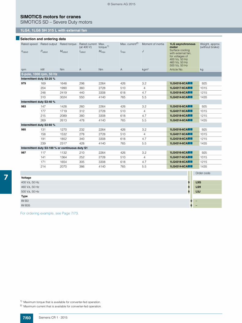
7/60 Siemens CR 1 · 2015
7
SIMOTICS motors for cranesSIMOTICS SD – Severe Duty motors
1LG4, 1LG6 SH 315 L with external fan
■ Selection and ordering data
For ordering example, see Page 7/73.
Rated speed Rated output Rated torque Rated current (at 400 V)
Max.torque1)
Max. current2) Moment of inertia 1LG asynchronous motorSurface coolingwith external fan,for voltages of400 VΔ, 50 Hz460 VΔ, 50 Hz500 VΔ, 50 Hz
Weight, approx.(without brake)
nrated Prated Mrated Irated Mmax Imax J
rpm kW Nm A Nm A kgm² Article No. kg
6-pole, 1000 rpm, 50 HzIntermittent duty S3-25 %
979 169 1648 298 2264 426 3.2 1LG4316-6CA■■ 925
204 1990 360 2728 510 4 1LG4317-6CA■■ 1015
248 2419 440 3308 618 4.7 1LG4318-6CA■■ 1215
310 3024 550 4140 765 5.5 1LG4314-6CA■■ 1435Intermittent duty S3-40 %
983 147 1428 260 2264 426 3.2 1LG4316-6CA■■ 925
177 1719 312 2728 510 4 1LG4317-6CA■■ 1015
215 2089 380 3308 618 4.7 1LG4318-6CA■■ 1215
269 2613 478 4140 765 5.5 1LG4314-6CA■■ 1435Intermittent duty S3-60 %
985 131 1270 232 2264 426 3.2 1LG4316-6CA■■ 925
158 1532 278 2728 510 4 1LG4317-6CA■■ 1015
191 1852 340 3308 618 4.7 1LG4318-6CA■■ 1215
239 2317 428 4140 765 5.5 1LG4314-6CA■■ 1435Intermittent duty S3-100 % or continuous duty S1
987 117 1132 210 2264 426 3.2 1LG4316-6CA■■ 925
141 1364 252 2728 510 4 1LG4317-6CA■■ 1015
171 1654 305 3308 618 4.7 1LG4318-6CA■■ 1215
214 2070 386 4140 765 5.5 1LG4314-6CA■■ 1435
Order code
Voltage
400 VΔ, 50 Hz 9 L5G
460 VΔ, 50 Hz 9 L5H
500 VΔ, 50 Hz 9 L5J
Type
IM B3 0 −
IM B35 6 −
1) Maximum torque that is available for converter-fed operation.2) Maximum current that is available for converter-fed operation.
© Siemens AG 2015

7/61Siemens CR 1 · 2015
7
■ Selection and ordering data (continued)
SIMOTICS motors for cranesSIMOTICS SD – Severe Duty motors
1LG4, 1LG6 SH 315 L with external fan
For ordering example, see Page 7/73.
Rated speed Rated output Rated torque Rated current (at 400 V)
Max.torque1)
Max. current2) Moment of inertia 1LG asynchronous motorSurface coolingwith forced ventilation,for voltage of690 V*, 50 Hz
Weight, approx.(without brake)
nrated Prated Mrated Irated Mmax Imax J
rpm kW Nm A Nm A kgm² Article No. kg
6-pole, 1000 rpm, 50 HzIntermittent duty S3-25 %
979 169 1648 298 2264 426 3.2 1LG6316-6CM8 ■ 1045
204 1990 360 2728 510 4 1LG6317-6CM8 ■ 1215
248 2419 440 3308 618 4.7 1LG6318-6CM8 ■ 1280Intermittent duty S3-40 %
983 147 1428 260 2264 426 3.2 1LG6316-6CM8 ■ 1045
177 1719 312 2728 510 4 1LG6317-6CM8 ■ 1215
215 2089 380 3308 618 4.7 1LG6318-6CM8 ■ 1280Intermittent duty S3-60 %
985 131 1270 232 2264 426 3.2 1LG6316-6CM8 ■ 1045
158 1532 278 2728 510 4 1LG6317-6CM8 ■ 1215
191 1852 340 3308 618 4.7 1LG6318-6CM8 ■ 1280Intermittent duty S3-100 % or continuous duty S1
987 117 1132 210 2264 426 3.2 1LG6316-6CM8 ■ 1045
141 1364 252 2728 510 4 1LG6317-6CM8 ■ 1215
171 1654 305 3308 618 4.7 1LG6318-6CM8 ■ 1280
Type
IM B3 0
IM B35 6
1) Maximum torque that is available for converter-fed operation.2) Maximum current that is available for converter-fed operation.
© Siemens AG 2015

7/62 Siemens CR 1 · 2015
7
■ Selection and ordering data (continued)
SIMOTICS motors for cranesSIMOTICS SD – Severe Duty motors
1LG4, 1LG6 SH 315 L with external fan
For ordering example, see Page 7/73.
Rated speed Rated output Rated torque Rated current (at 400 V)
Max.torque1)
Max. current2) Moment of inertia 1LG asynchronous motorSurface coolingwith external fan,for voltages of400 VΔ, 50 Hz460 VΔ, 50 Hz500 VΔ, 50 Hz
Weight, approx.(without brake)
nrated Prated Mrated Irated Mmax Imax J
rpm kW Nm A Nm A kgm² Article No. kg
8-pole, 750 rpm, 50 HzIntermittent duty S3-25 %
727 146 1918 275 2622 390 3.1 1LG4316-8CB■■ 900
178 2338 334 3192 468 3.9 1LG4317-8CB■■ 1055
215 2824 402 3840 562 4.5 1LG4318-8CB■■ 1135
259 3402 465 4646 655 5.5 1LG4314-8CB■■ 1415Intermittent duty S3-40 %
731 127 1659 236 2622 390 3.1 1LG4316-8CB■■ 900
155 2025 286 3192 468 3.9 1LG4317-8CB■■ 1055
186 2430 342 3840 562 4.5 1LG4318-8CB■■ 1135
225 2939 353 4646 655 5.5 1LG4314-8CB■■ 1415Intermittent duty S3-60 %
734 113 1470 207 2622 390 3.1 1LG4316-8CB■■ 900
139 1809 255 3192 468 3.9 1LG4317-8CB■■ 1055
166 2160 303 3840 562 4.5 1LG4318-8CB■■ 1135
202 2628 353 4646 655 5.5 1LG4314-8CB■■ 1415Intermittent duty S3-100 % or continuous duty S1
736 101 1311 187 2622 390 3.1 1LG4316-8CB■■ 900
123 1596 227 3192 468 3.9 1LG4317-8CB■■ 1055
148 1920 272 3840 562 4.5 1LG4318-8CB■■ 1135
179 2323 320 4646 655 5.5 1LG4314-8CB■■ 1415
Order code
Voltage
400 VΔ, 50 Hz 9 L5G
460 VΔ, 50 Hz 9 L5H
500 VΔ, 50 Hz 9 L5J
Type
IM B3 0 −
IM B35 6 −
1) Maximum torque that is available for converter-fed operation.2) Maximum current that is available for converter-fed operation.
© Siemens AG 2015

7/63Siemens CR 1 · 2015
7
■ Selection and ordering data (continued)
SIMOTICS motors for cranesSIMOTICS SD – Severe Duty motors
1LG4, 1LG6 SH 315 L with external fan
For ordering example, see Page 7/73.
Rated speed Rated output Rated torque Rated current (at 400 V)
Max.torque1)
Max. current2) Moment of inertia 1LG asynchronous motorSurface coolingwith forced ventilation,for voltage of690 V*, 50 Hz
Weight, approx.(without brake)
nrated Prated Mrated Irated Mmax Imax J
rpm kW Nm A Nm A kgm² Article No. kg
8-pole, 750 rpm, 50 HzIntermittent duty S3-25 %
727 146 1918 275 2622 390 3.1 1LG6316-8CM8 ■ 1040
178 2338 334 3192 468 3.9 1LG6317-8CM8 ■ 1135
215 2824 402 3840 562 4.5 1LG6318-8CM8 ■ 1305Intermittent duty S3-40 %
731 127 1659 236 2622 390 3.1 1LG6316-8CM8 ■ 1040
155 2025 286 3192 468 3.9 1LG6317-8CM8 ■ 1135
186 2430 342 3840 562 4.5 1LG6318-8CM8 ■ 1305Intermittent duty S3-60 %
734 113 1470 207 2622 390 3.1 1LG6316-8CM8 ■ 1040
139 1809 255 3192 468 3.9 1LG6317-8CM8 ■ 1135
166 2160 303 3840 562 4.5 1LG6318-8CM8 ■ 1305Intermittent duty S3-100 % or continuous duty S1
736 101 1311 187 2622 390 3.1 1LG6316-8CM8 ■ 1040
123 1596 227 3192 468 3.9 1LG6317-8CM8 ■ 1135
148 1920 272 3840 562 4.5 1LG6318-8CM8 ■ 1305
Type
IM B3 0
IM B35 6
1) Maximum torque that is available for converter-fed operation.2) Maximum current that is available for converter-fed operation.
© Siemens AG 2015

7/64 Siemens CR 1 · 2015
7
■ Selection and ordering data (continued)
SIMOTICS motors for cranesSIMOTICS SD – Severe Duty motors
1LG4, 1LG6 SH 315 L with external fan
For ordering example, see Page 7/73.
Rated speed Rated output Rated torque Rated current (at 400 V)
Max.torque1)
Max. current2) Moment of inertia 1LG asynchronous motorSurface coolingwith external fan,for voltages of400 VΔ, 69 Hz460 VΔ, 69 Hz500 VΔ, 69 Hz
Weight, approx.(without brake)
nrated Prated Mrated Irated Mmax Imax J
rpm kW Nm A Nm A kgm² Article No. kg
6-pole, 1380 rpm, 69 HzIntermittent duty S3-25 %
1356 218 1535 388 2096 536 3.2 1LG4316-6CA■■ 925
261 1838 455 2514 655 4 1LG4317-6CA■■ 1015
318 2240 554 3060 788 4.7 1LG4318-6CA■■ 1215
397 2796 695 3828 990 5.5 1LG4314-6CA■■ 1435Intermittent duty S3-40 %
1361 189 1326 335 2096 536 3.2 1LG4316-6CA■■ 925
227 1593 396 2514 655 4 1LG4317-6CA■■ 1015
276 1937 477 3060 788 4.7 1LG4318-6CA■■ 1215
345 2421 598 3828 990 5.5 1LG4314-6CA■■ 1435Intermittent duty S3-60 %
1365 168 1175 298 2096 536 3.2 1LG4316-6CA■■ 925
202 1413 353 2514 655 4 1LG4317-6CA■■ 1015
245 1714 424 3060 788 4.7 1LG4318-6CA■■ 1215
307 2148 535 3828 990 5.5 1LG4314-6CA■■ 1435Intermittent duty S3-100 % or continuous duty S1
1367 150 1048 268 2096 536 3.2 1LG4316-6CA■■ 925
180 1257 316 2514 655 4 1LG4317-6CA■■ 1015
219 1530 388 3060 788 4.7 1LG4318-6CA■■ 1215
274 1914 476 3828 990 5.5 1LG4314-6CA■■ 1435
Order code
Voltage
400 VΔ, 69 Hz 9 L5N
460 VΔ, 69 Hz 9 L5P
500 VΔ, 69 Hz 9 L5Q
Type
IM B3 0 −
IM B35 6 −
1) Maximum torque that is available for converter-fed operation.2) Maximum current that is available for converter-fed operation.
© Siemens AG 2015

7/65Siemens CR 1 · 2015
7
■ Selection and ordering data (continued)
SIMOTICS motors for cranesSIMOTICS SD – Severe Duty motors
1LG4, 1LG6 SH 315 L with external fan
For ordering example, see Page 7/73.
Rated speed Rated output Rated torque Rated current (at 400 V)
Max.torque1)
Max. current2) Moment of inertia 1LG asynchronous motorSurface coolingwith forced ventilation,for voltage of690 V*, 69 Hz
Weight, approx.(without brake)
nrated Prated Mrated Irated Mmax Imax J
rpm kW Nm A Nm A kgm² Article No. kg
6-pole, 1380 rpm, 69 HzIntermittent duty S3-25 %
1356 218 1535 388 2096 536 3.2 1LG6316-6CM■■ 1045
261 1838 455 2514 655 4 1LG6317-6CM■■ 1215
318 2240 554 3060 788 4.7 1LG6318-6CM■■ 1280Intermittent duty S3-40 %
1361 189 1326 335 2096 536 3.2 1LG6316-6CM■■ 1045
227 1593 396 2514 655 4 1LG6317-6CM■■ 1215
276 1937 477 3060 788 4.7 1LG6318-6CM■■ 1280Intermittent duty S3-60 %
1365 168 1175 298 2096 536 3.2 1LG6316-6CM■■ 1045
202 1413 353 2514 655 4 1LG6317-6CM■■ 1215
245 1714 424 3060 788 4.7 1LG6318-6CM■■ 1280Intermittent duty S3-100 % or continuous duty S1
1367 150 1048 268 2096 536 3.2 1LG6316-6CM■■ 1045
180 1257 316 2514 655 4 1LG6317-6CM■■ 1215
219 1530 388 3060 788 4.7 1LG6318-6CM■■ 1280
Order code
Voltage
690 V*, 69 Hz 9 L5W
Type
IM B3 0 −
IM B35 6 −
1) Maximum torque that is available for converter-fed operation.2) Maximum current that is available for converter-fed operation.
© Siemens AG 2015

7/66 Siemens CR 1 · 2015
7
■ Selection and ordering data (continued)
SIMOTICS motors for cranesSIMOTICS SD – Severe Duty motors
1LG4, 1LG6 SH 315 L with external fan
For ordering example, see Page 7/73.
Rated speed Rated output Rated torque Rated current (at 400 V)
Max.torque1)
Max. current2) Moment of inertia 1LG asynchronous motorSurface coolingwith external fan,for voltages of400 VΔ, 69 Hz460 VΔ, 69 Hz500 VΔ, 69 Hz
Weight, approx.(without brake)
nrated Prated Mrated Irated Mmax Imax J
rpm kW Nm A Nm A kgm² Article No. kg
8-pole, 1035 rpm, 69 HzIntermittent duty S3-25 %
1009 187 1770 351 2410 490 3.1 1LG4316-8CB■■ 900
228 2158 418 2934 585 3.9 1LG4317-8CB■■ 1055
274 2593 502 3532 700 4.5 1LG4318-8CB■■ 1135
332 3142 600 4280 846 5.5 1LG4314-8CB■■ 1415Intermittent duty S3-40 %
1015 162 1524 300 2410 490 3.1 1LG4316-8CB■■ 900
198 1863 357 2934 585 3.9 1LG4317-8CB■■ 1055
238 2239 427 3532 700 4.5 1LG4318-8CB■■ 1135
288 2710 512 4280 846 5.5 1LG4314-8CB■■ 1415Intermittent duty S3-60 %
1019 144 1350 266 2410 490 3.1 1LG4316-8CB■■ 900
176 1649 315 2934 585 3.9 1LG4317-8CB■■ 1055
212 1987 378 3532 700 4.5 1LG4318-8CB■■ 1135
256 2399 455 4280 846 5.5 1LG4314-8CB■■ 1415Intermittent duty S3-100 % or continuous duty S1
1022 129 1205 239 2410 490 3.1 1LG4316-8CB■■ 900
157 1467 280 2934 585 3.9 1LG4317-8CB■■ 1055
189 1766 336 3532 700 4.5 1LG4318-8CB■■ 1135
229 2140 408 4280 846 5.5 1LG4314-8CB■■ 1415
Order code
Voltage
400 VΔ, 69 Hz 9 L5N
460 VΔ, 69 Hz 9 L5P
500 VΔ, 69 Hz 9 L5Q
Type
IM B3 0 −
IM B35 6 −
1) Maximum torque that is available for converter-fed operation.2) Maximum current that is available for converter-fed operation.
© Siemens AG 2015
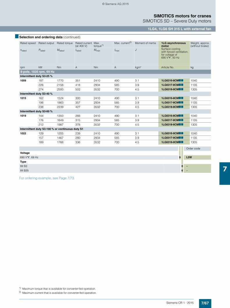
7/67Siemens CR 1 · 2015
7
■ Selection and ordering data (continued)
SIMOTICS motors for cranesSIMOTICS SD – Severe Duty motors
1LG4, 1LG6 SH 315 L with external fan
For ordering example, see Page 7/73.
Rated speed Rated output Rated torque Rated current (at 400 V)
Max.torque1)
Max. current2) Moment of inertia 1LG asynchronous motorSurface coolingwith forced ventilation,for voltage of690 V*, 50 Hz
Weight, approx.(without brake)
nrated Prated Mrated Irated Mmax Imax J
rpm kW Nm A Nm A kgm² Article No. kg
8-pole, 1035 rpm, 69 HzIntermittent duty S3-25 %
1009 187 1770 351 2410 490 3.1 1LG6316-8CM■■ 1040
228 2158 418 2934 585 3.9 1LG6317-8CM■■ 1135
274 2593 502 3532 700 4.5 1LG6318-8CM■■ 1305Intermittent duty S3-40 %
1015 162 1524 300 2410 490 3.1 1LG6316-8CM■■ 1040
198 1863 357 2934 585 3.9 1LG6317-8CM■■ 1135
238 2239 427 3532 700 4.5 1LG6318-8CM■■ 1305Intermittent duty S3-60 %
1019 144 1350 266 2410 490 3.1 1LG6316-8CM■■ 1040
176 1649 315 2934 585 3.9 1LG6317-8CM■■ 1135
212 1987 378 3532 700 4.5 1LG6318-8CM■■ 1305Intermittent duty S3-100 % or continuous duty S1
1022 129 1205 239 2410 490 3.1 1LG6316-8CM■■ 1040
157 1467 280 2934 585 3.9 1LG6317-8CM■■ 1135
189 1766 336 3532 700 4.5 1LG6318-8CM■■ 1305
Order code
Voltage
690 V*, 69 Hz 9 L5W
Type
IM B3 0 −
IM B35 6 −
1) Maximum torque that is available for converter-fed operation.2) Maximum current that is available for converter-fed operation.
© Siemens AG 2015

7/68 Siemens CR 1 · 2015
7
■ Selection and ordering data (continued)
SIMOTICS motors for cranesSIMOTICS SD – Severe Duty motors
1LG4, 1LG6 SH 315 L with external fan
For ordering example, see Page 7/73.
Rated speed Rated output Rated torque Rated current (at 400 V)
Max.torque1)
Max. current2) Moment of inertia 1LG asynchronous motorSurface coolingwith external fan,for voltages of400 VΔ, 87 Hz460 VΔ, 87 Hz500 VΔ, 87 Hz
Weight, approx.(without brake)
nrated Prated Mrated Irated Mmax Imax J
rpm kW Nm A Nm A kgm² Article No. kg
6-pole, 1740 rpm, 87 HzIntermittent duty S3-25 %
1714 262 1460 461 2002 646 3.2 1LG4316-6CA■■ 925
318 1772 548 2424 782 4 1LG4317-6CA■■ 1015
384 2140 665 2932 932 4.7 1LG4318-6CA■■ 1215
481 2680 848 3674 1195 5.5 1LG4314-6CA■■ 1435Intermittent duty S3-40 %
1721 228 1265 397 2002 646 3.2 1LG4316-6CA■■ 925
276 1532 469 2424 782 4 1LG4317-6CA■■ 1015
334 1853 572 2932 932 4.7 1LG4318-6CA■■ 1215
418 2319 728 3674 1195 5.5 1LG4314-6CA■■ 1435Intermittent duty S3-60 %
1724 203 1124 355 2002 646 3.2 1LG4316-6CA■■ 925
245 1357 420 2424 782 4 1LG4317-6CA■■ 1015
297 1645 509 2932 932 4.7 1LG4318-6CA■■ 1215
372 2061 648 3674 1195 5.5 1LG4314-6CA■■ 1435Intermittent duty S3-100 % or continuous duty S1
1726 181 1001 318 2002 646 3.2 1LG4316-6CA■■ 925
219 1212 380 2424 782 4 1LG4317-6CA■■ 1015
265 1466 454 2932 932 4.7 1LG4318-6CA■■ 1215
332 1837 580 3674 1195 5.5 1LG4314-6CA■■ 1435
Order code
Voltage
400 VΔ, 87 Hz 9 L5R
460 VΔ, 87 Hz 9 L5S
500 VΔ, 87 Hz 9 L5T
Type
IM B3 0 −
IM B35 6 −
1) Maximum torque that is available for converter-fed operation.2) Maximum current that is available for converter-fed operation.
© Siemens AG 2015

7/69Siemens CR 1 · 2015
7
■ Selection and ordering data (continued)
SIMOTICS motors for cranesSIMOTICS SD – Severe Duty motors
1LG4, 1LG6 SH 315 L with external fan
For ordering example, see Page 7/73.
Rated speed Rated output Rated torque Rated current (at 400 V)
Max.torque1)
Max. current2) Moment of inertia 1LG asynchronous motorSurface coolingwith forced ventilation,for voltage of690 V*, 87 Hz
Weight, approx.(without brake)
nrated Prated Mrated Irated Mmax Imax J
rpm kW Nm A Nm A kgm² Article No. kg
6-pole, 1740 rpm, 87 HzIntermittent duty S3-25 %
1714 262 1460 461 2002 646 3.2 1LG6316-6CM■■ 1045
318 1772 548 2424 782 4 1LG6317-6CM■■ 1215
384 2140 665 2932 932 4.7 1LG6318-6CM■■ 1280Intermittent duty S3-40 %
1721 228 1265 397 2002 646 3.2 1LG6316-6CM■■ 1045
276 1532 469 2424 782 4 1LG6317-6CM■■ 1215
334 1853 572 2932 932 4.7 1LG6318-6CM■■ 1280Intermittent duty S3-60 %
1724 203 1124 355 2002 646 3.2 1LG6316-6CM■■ 1045
245 1357 420 2424 782 4 1LG6317-6CM■■ 1215
297 1645 509 2932 932 4.7 1LG6318-6CM■■ 1280Intermittent duty S3-100 % or continuous duty S1
1726 181 1001 318 2002 646 3.2 1LG6316-6CM■■ 1045
219 1212 380 2424 782 4 1LG6317-6CM■■ 1215
265 1466 454 2932 932 4.7 1LG6318-6CM■■ 1280
Order code
Voltage
690 V*, 87 Hz 9 L5X
Type
IM B3 0 −
IM B35 6 −
1) Maximum torque that is available for converter-fed operation.2) Maximum current that is available for converter-fed operation.
© Siemens AG 2015

7/70 Siemens CR 1 · 2015
7
■ Selection and ordering data (continued)
SIMOTICS motors for cranesSIMOTICS SD – Severe Duty motors
1LG4, 1LG6 SH 315 L with external fan
For ordering example, see Page 7/73.
Rated speed Rated output Rated torque Rated current (at 400 V)
Max.torque1)
Max. current2) Moment of inertia 1LG asynchronous motorSurface coolingwith external fan,for voltages of400 VΔ, 69 Hz460 VΔ, 69 Hz500 VΔ, 69 Hz
Weight, approx.(without brake)
nrated Prated Mrated Irated Mmax Imax J
rpm kW Nm A Nm A kgm² Article No. kg
8-pole, 1035 rpm, 69 HzIntermittent duty S3-25 %
1275 226 1693 412 2308 578 3.1 1LG4316-8CB■■ 900
277 2075 508 2826 735 3.9 1LG4317-8CB■■ 1055
332 2487 609 3388 855 4.5 1LG4318-8CB■■ 1135
402 3011 712 4098 1005 5.5 1LG4314-8CB■■ 1415Intermittent duty S3-40 %
1282 196 1460 351 2308 578 3.1 1LG4316-8CB■■ 900
241 1795 434 2826 735 3.9 1LG4317-8CB■■ 1055
288 2145 522 3388 855 4.5 1LG4318-8CB■■ 1135
349 2600 610 4098 1005 5.5 1LG4314-8CB■■ 1415Intermittent duty S3-60 %
1287 175 1299 315 2308 578 3.1 1LG4316-8CB■■ 900
214 1588 383 2826 735 3.9 1LG4317-8CB■■ 1055
256 1900 460 3388 855 4.5 1LG4318-8CB■■ 1135
310 2300 538 4098 1005 5.5 1LG4314-8CB■■ 1415Intermittent duty S3-100 % or continuous duty S1
1291 156 1154 280 2308 578 3.1 1LG4316-8CB■■ 900
191 1413 340 2826 735 3.9 1LG4317-8CB■■ 1055
229 1694 410 3388 855 4.5 1LG4318-8CB■■ 1135
277 2049 478 4098 1005 5.5 1LG4314-8CB■■ 1415
Order code
Voltage
400 VΔ, 69 Hz 9 L5R
460 VΔ, 69 Hz 9 L5S
500 VΔ, 69 Hz 9 L5T
Type
IM B3 0 −
IM B35 6 −
1) Maximum torque that is available for converter-fed operation.2) Maximum current that is available for converter-fed operation.
© Siemens AG 2015

7/71Siemens CR 1 · 2015
7
■ Selection and ordering data (continued)
SIMOTICS motors for cranesSIMOTICS SD – Severe Duty motors
1LG4, 1LG6 SH 315 L with external fan
For ordering example, see Page 7/73.
Rated speed Rated output Rated torque Rated current (at 400 V)
Max.torque1)
Max. current2) Moment of inertia 1LG asynchronous motorSurface coolingwith forced ventilation,for voltage of690 V*, 87 Hz
Weight, approx.(without brake)
nrated Prated Mrated Irated Mmax Imax J
rpm kW Nm A Nm A kgm² Article No. kg
8-pole, 1035 rpm, 87 HzIntermittent duty S3-25 %
1275 226 1693 412 2308 578 3.1 1LG6316-8CM■■ 1040
277 2075 508 2826 735 3.9 1LG6317-8CM■■ 1135
332 2487 609 3388 855 4.5 1LG6318-8CM■■ 1305Intermittent duty S3-40 %
1282 196 1460 351 2308 578 3.1 1LG6316-8CM■■ 1040
241 1795 434 2826 735 3.9 1LG6317-8CM■■ 1135
288 2145 522 3388 855 4.5 1LG6318-8CM■■ 1305Intermittent duty S3-60 %
1287 175 1299 315 2308 578 3.1 1LG6316-8CM■■ 1040
214 1588 383 2826 735 3.9 1LG6317-8CM■■ 1135
256 1900 460 3388 855 4.5 1LG6318-8CM■■ 1305Intermittent duty S3-100 % or continuous duty S1
1291 156 1154 280 2308 578 3.1 1LG6316-8CM■■ 1040
191 1413 340 2826 735 3.9 1LG6317-8CM■■ 1135
229 1694 410 3388 855 4.5 1LG6318-8CM■■ 1305
Order code
Voltage
690 V*, 87 Hz 9 L5X
Type
IM B3 0 −
IM B35 6 −
1) Maximum torque that is available for converter-fed operation.2) Maximum current that is available for converter-fed operation.
© Siemens AG 2015

7/72 Siemens CR 1 · 2015
7
SIMOTICS motors for cranesSIMOTICS SD – Severe Duty motors
Options
■ Options
Options or order codes (supplement "-Z" is required)
• This order code only determines the price of the version – additional plain text is required.
Order No. supplement "-Z" with order code and plain text, if re-quired.
Order code Description
A11 Motor protection through PTC thermistor with 3 embedded temperature sensors for tripping
A12 Motor protection through PTC thermistor with 6 embedded temperature sensors for tripping and alarm
A23 Motor temperature detection with embedded temperature sensor KTY 84-130
J15 Mounting of rotary pulse encoder HOG 10 DN 1024 I, terminal box moisture protection
J16 Mounting of rotary pulse encoder HOG 10 DN 1024 I, terminal box dust protection
K45 Standstill heating for 230 V
K46 Standstill heating for 115 V
L27 Insulated bearing cartridge
Y54 • and special finish RAL ….
Special finish in other standard RAL colors: RAL 1015, 1019, 2003, 2004, 3007, 5007, 5009, 5010, 5012, 5015, 5017, 5018, 5019, 6019, 7000, 7004, 7011, 7016, 7022, 7033
K26 Special finish in RAL 7030, stone gray, coat thickness 90 µm
M91 Special "Offshore" finish in RAL 7030, stone gray, coat thickness 220 µm
Y73 • and identifica-tion code
Non-standard cable entry holes, specify size and number in plain text
K09 Terminal box on RHS
K10 Terminal box on LHS
K83 Rotation of the terminal box through 90°, entry from DE
K84 Rotation of the terminal box through 90°, entry from NDE
K85 Rotation of terminal box through 180°
K31 Second rating plate, supplied separately packed
Y74 Mounting of rotary pulse encoder HOG 10 DN 1024 I + FSL (speed ... rpm), terminal box moisture protection
Y76 Mounting of rotary pulse encoder HOG 10 DN 1024 I + FSL (speed ... rpm) terminal box dust protection
Y80 • and identifica-tion code
Extra rating plate or rating plate with different data
Y81 • and identifica-tion code
Non-standard voltage and/or frequency of the external fan motor, standstill heating
Y82 • and identifica-tion code
Extra rating plate with identification code
© Siemens AG 2015

7/73Siemens CR 1 · 2015
7
■ Options (continued)
SIMOTICS motors for cranesSIMOTICS SD – Severe Duty motors
Options
Ordering example
Selection criteria Requirement Structure of the Article No.
Motor type Standard motor with improved efficiency, IP55 degree of protection, cast-iron version
1LG4■■■-■■■■■
Shaft height 315 L 1LG4316-■■■■■
No. of poles/speed 6-pole 1LG4316-6■■■■
Version Crane version 1LG4316-6CA■■
Voltage/frequency 400 VΔ, 50 Hz 1LG4316-6CA9■L5G
Type IM B3 1LG4316-6CA90L5G
Special versionMotor temperature detection with embedded temperature sensor KTY 84-130
1LG4316-6CA90-ZL5G+A23
Standstill heating for 230 V 1LG4316-6CA90-ZL5G+A23+K45
Mounting of rotary pulse encoder HOG 10 DN 1024 I + FSL (speed ... rpm) terminal box dust protection
1LG4316-6CA90-ZL5G+A23+K45+Y76
Complete ordering information for required version of hoist motor 1LG4316-6CA90-Z L5G+A23+K45+Y76
© Siemens AG 2015
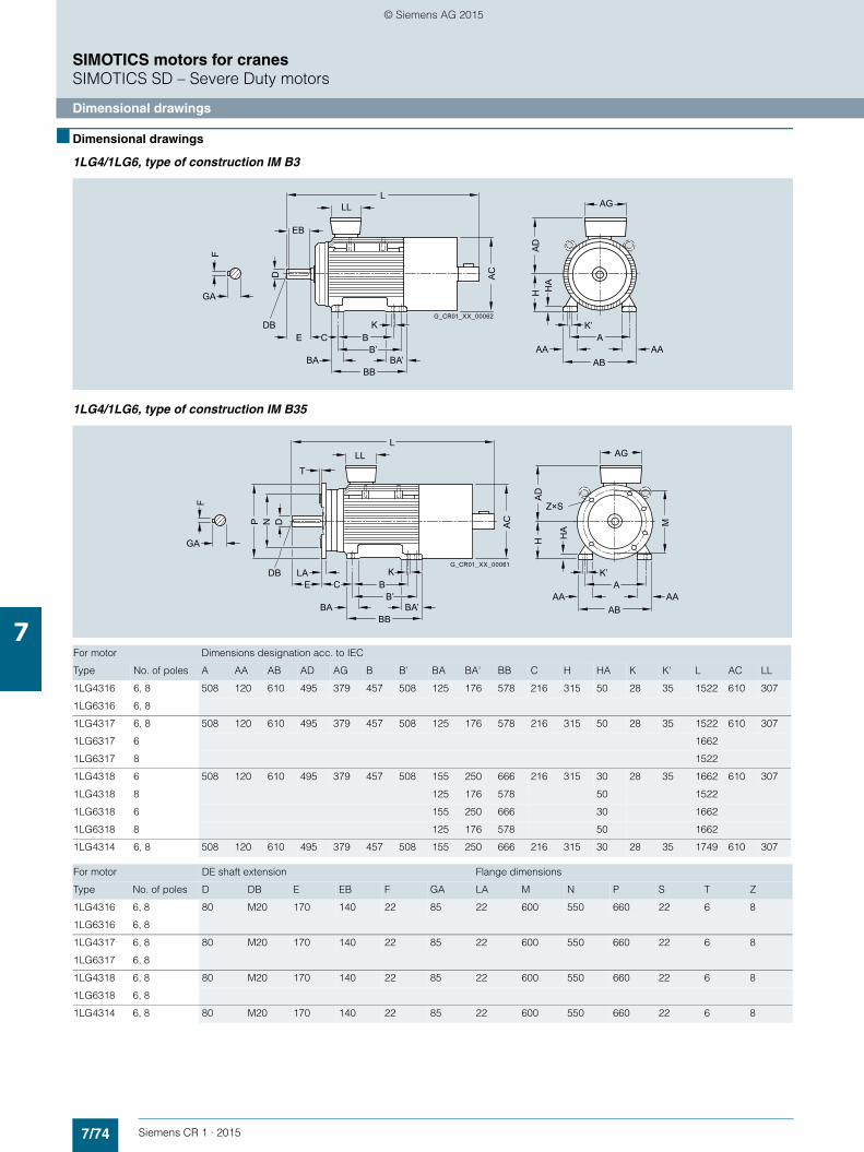
7/74 Siemens CR 1 · 2015
7
SIMOTICS motors for cranesSIMOTICS SD – Severe Duty motors
Dimensional drawings
■ Dimensional drawings
1LG4/1LG6, type of construction IM B3
1LG4/1LG6, type of construction IM B35
HA
HA
D
AAA
K’
AAAB
AG
E C BB’
K
BBBA BA’
LL
EB
L
AC
F
GA
D
G_CR01_XX_00062DB
For motor Dimensions designation acc. to IEC
Type No. of poles A AA AB AD AG B B' BA BA' BB C H HA K K' L AC LL
1LG4316 6, 8 508 120 610 495 379 457 508 125 176 578 216 315 50 28 35 1522 610 307
1LG6316 6, 8
1LG4317 6, 8 508 120 610 495 379 457 508 125 176 578 216 315 50 28 35 1522 610 307
1LG6317 6 1662
1LG6317 8 1522
1LG4318 6 508 120 610 495 379 457 508 155 250 666 216 315 30 28 35 1662 610 307
1LG4318 8 125 176 578 50 1522
1LG6318 6 155 250 666 30 1662
1LG6318 8 125 176 578 50 1662
1LG4314 6, 8 508 120 610 495 379 457 508 155 250 666 216 315 30 28 35 1749 610 307
For motor DE shaft extension Flange dimensions
Type No. of poles D DB E EB F GA LA M N P S T Z
1LG4316 6, 8 80 M20 170 140 22 85 22 600 550 660 22 6 8
1LG6316 6, 8
1LG4317 6, 8 80 M20 170 140 22 85 22 600 550 660 22 6 8
1LG6317 6, 8
1LG4318 6, 8 80 M20 170 140 22 85 22 600 550 660 22 6 8
1LG6318 6, 8
1LG4314 6, 8 80 M20 170 140 22 85 22 600 550 660 22 6 8
E C BB’
K
BBBA BA’
LL
T
L
AC
HA
HA
D
M
AAA
K’
AA
Z×S
AB
AG
LADB
F
GA
DNP
G_CR01_XX_00061
© Siemens AG 2015
Siemens CR 1 · 2015
88/2 Contact at Cranes
8/3 Online Services8/3 Information and Ordering Options on
the Internet and DVD8/4 Information and Download Center, Social
Media, Mobile Media
8/5 Partner at Siemens
8/6 Industry Services8/6 Your machines and plant can do more –
with Industry Services.8/7 Industry Services for the entire life cycle
8/11 Applications
8/12 Crane-specific training8/12 SITRAIN8/13 SIMOCRANE course overview
8/14 Spares on Web
8/15 My Documentation Manager
8/16 Documentation8/16 General documentation
8/17 CAD CREATOR
Services and documentation
© Siemens AG 2015

8/2 Siemens CR 1 · 2015
8
Services and documentationContact at Cranes
■ Overview
Your personal contact partner and further information on cranes can be found at:
www.siemens.com/cranes
Siemens Internet addresses:
The latest information about SIMOTION products, product support, and FAQs can be found on the Internet at www.siemens.com/simotion
Information on product support can be found on the Internet at https://support.industry.siemens.com/cs
The latest information about SINAMICS products, product sup-port, and FAQs can be found on the Internet atwww.siemens.com/sinamics
The latest information about SIMOCRANE products, product support, and FAQs can be found on the Internet at
https://support.industry.siemens.com/cs/
→ Product Support → (Enter search term) SIMOCRANE
Application notes:
Available on the Internet at
https://support.industry.siemens.com/cs/
→ Application Examples → (Enter search term) SIMOCRANE
Siemens PD LD Application Support Cranes
e-mail: [email protected](mailto: [email protected])
Training:
Siemens Cranes offers crane-specific training courses:
http://www.siemens.nl/training/cranes
If you have any additional questions please contact your local Siemens sales person.
© Siemens AG 2015
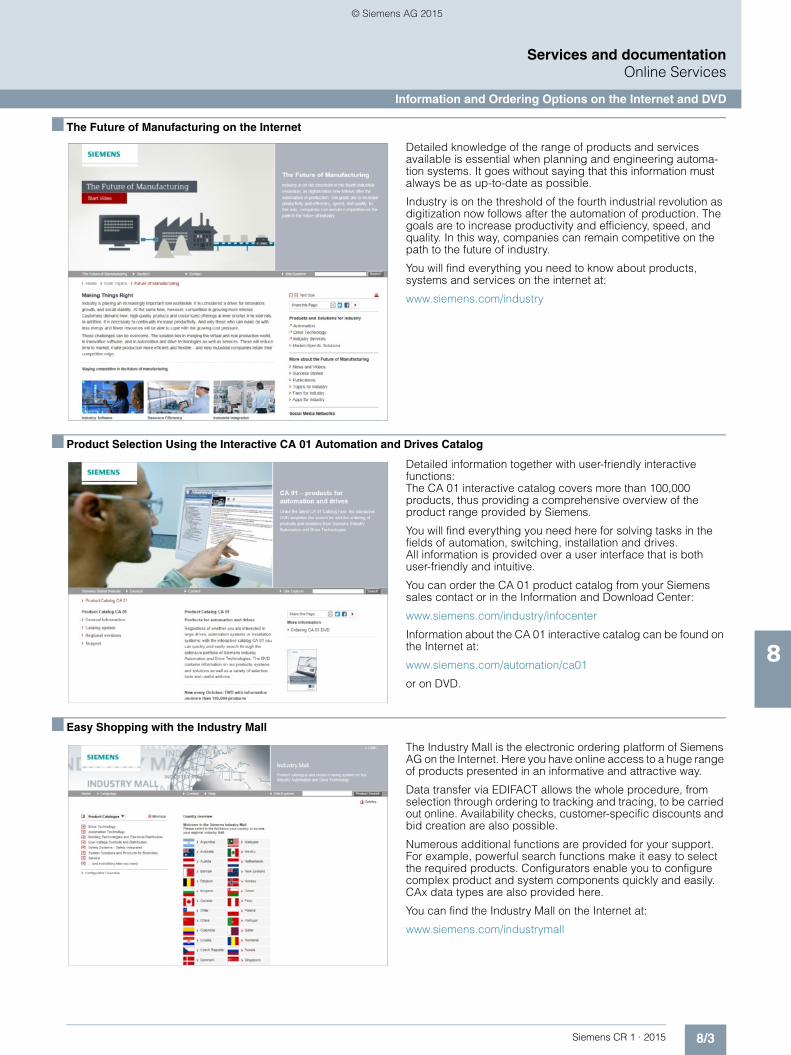
8/3Siemens CR 1 · 2015
Services and documentationOnline Services
Information and Ordering Options on the Internet and DVD
8
■ The Future of Manufacturing on the Internet
Detailed knowledge of the range of products and services available is essential when planning and engineering automa-tion systems. It goes without saying that this information must always be as up-to-date as possible.
Industry is on the threshold of the fourth industrial revolution as digitization now follows after the automation of production. The goals are to increase productivity and efficiency, speed, and quality. In this way, companies can remain competitive on the path to the future of industry.
You will find everything you need to know about products, systems and services on the internet at:
www.siemens.com/industry
■ Product Selection Using the Interactive CA 01 Automation and Drives Catalog
Detailed information together with user-friendly interactive functions: The CA 01 interactive catalog covers more than 100,000 products, thus providing a comprehensive overview of the product range provided by Siemens.
You will find everything you need here for solving tasks in the fields of automation, switching, installation and drives. All information is provided over a user interface that is both user-friendly and intuitive.
You can order the CA 01 product catalog from your Siemens sales contact or in the Information and Download Center:
www.siemens.com/industry/infocenter
Information about the CA 01 interactive catalog can be found on the Internet at:
www.siemens.com/automation/ca01
or on DVD.
■ Easy Shopping with the Industry Mall
The Industry Mall is the electronic ordering platform of Siemens AG on the Internet. Here you have online access to a huge range of products presented in an informative and attractive way.
Data transfer via EDIFACT allows the whole procedure, from selection through ordering to tracking and tracing, to be carried out online. Availability checks, customer-specific discounts and bid creation are also possible.
Numerous additional functions are provided for your support. For example, powerful search functions make it easy to select the required products. Configurators enable you to configure complex product and system components quickly and easily. CAx data types are also provided here.
You can find the Industry Mall on the Internet at:
www.siemens.com/industrymall
© Siemens AG 2015

8/4 Siemens CR 1 · 2015
Services and documentationOnline Services
Information and Download Center, Social Media, Mobile Media
8
■ Downloading Catalogs
In addition to numerous other useful documents, you can also find the catalogs listed on the back inside cover of this catalog in the Information and Download Center. You can download these catalogs in PDF format without having to register.
The filter dialog above the first catalog displayed makes it possible to carry out targeted searches. If you enter "MD 3" for example, you will find both the MD 30.1 and MD 31.1 catalogs. If you enter "IC 10", both the IC 10 catalog and the associated news or add-ons are displayed.
Visit us at:
www.siemens.com/industry/infocenter
■ Social and Mobile Media
Connect with Siemens through social media: visit our social networking sites for a wealth of useful information, demos on products and services, the opportunity to provide feedback, to exchange information and ideas with customers and other Siemens employees, and much, much more. Stay in the know and follow us on the ever-expanding global network of social media.
To find out more about Siemens' current social media activities, visit us at:
www.siemens.com/socialmedia
Or via our product pages at:
www.siemens.com/automation or www.siemens.com/drives
Connect with Siemens Industry at our central access point to read all the news on the future of manufacturing, watch current videos and inform yourself about all the latest industry developments:
www.siemens.com/future-of-manufacturing/news.html
Discover the world of Siemens.
We are also constantly expanding our offering of cross-platform apps for smartphones and tablets. You will find the current Siemens apps at the App Store (iOS) or at Google Play (Android):
https://itunes.apple.com/en/app/siemens/id452698392?mt=8
https://play.google.com/store/search?q=siemens
The Siemens app, for example, tells you all about the history, latest developments and future plans of the company – with informative pictures, fascinating reports and the most recent press releases.
© Siemens AG 2015

8/5Siemens CR 1 · 2015
Services and documentationPartner at Siemens
8
At Siemens we are resolutely pursuing the same goal: long-term improvement of your competitive ability. We are committed to this goal. Thanks to our commitment, we continue to set new standards in automation and drive technology. In all industries – worldwide.
At your service locally, around the globe for consulting, sales, training, service, support, spare parts ... on the entire Industry Automation and Drive Technologies range.
Your personal contact can be found in our Contacts Database at:www.siemens.com/automation/partner
You start by selecting • the required competence, • products and branches, • a country, • a city
or by a• location search or• person search.
© Siemens AG 2015

8/6 Siemens CR 1 · 2015
Services and documentationIndustry Services
Your machines and plant can do more – with Industry Services.
8
Whether it is production or process industry - in view of rising cost pressure, growing energy costs, and increasingly stringent environmental regulations, services for industry are a crucial competitive factor in manufacturing as well as in process indus-tries.
All over the world Siemens supports its customers with product, system, and application-related services throughout the entire life cycle of a plant. Right from the earliest stages of planning, engineering, and building, all the way to operation and modern-ization. These services enable customers to benefit from the Siemens experts’ unique technological and product knowledge and industry expertise.
Thus downtimes are reduced and the utilization of resources is optimized. The bottom line: increased plant productivity, flexibil-ity, and efficiency, plus reduced overall costs.
Discover all advantages of our service portfolio: www.siemens.com/industry-services
Siemens supports its clients with technology based Services across a plants entire life cycle.
G_DA65_EN_00270
Online SupportTechnical Support
Spare PartsRepair ServicesField Services
Training
Engineer & Build
Operation
Modernization
PlanningPlanning
Modernization
Operation
Engineer & Build
© Siemens AG 2015

8/7Siemens CR 1 · 2015
Services and documentationIndustry Services
Industry Services for the entire life cycle
8
Online Support
Online support is a comprehensive information system for all questions relating to products, systems, and solutions that Siemens has developed for industry over time. With more than 300,000 documents, examples and tools, it offers users of auto-mation and drive technology a way to quickly find up-to-date in-formation. The 24-hour service enables direct, central access to detailed product information as well as numerous solution exam-ples for programming, configuration and application.
The content, in six languages, is increasingly multimediabased – and now also available as a mobile app. Online support’s “Technical Forum” offers users the opportunity to share informa-tion with each other. The “Support Request” option can be used to contact Siemens’ technical support experts. The latest con-tent, software updates, and news via newsletters and Twitter en-sure that industry users are always up to date.
www.siemens.com/industry/onlinesupport
Online Support App
Using the Online Support app, you can access over 300,000 documents covering all Siemens industrial products - anywhere, any time. Regardless of whether you need help implementing your project, fault-finding, expanding your system or are plan-ning a new machine.
You have access to FAQs, manuals, certificates, characteristics curves, application examples, product notices (e.g. announce-ments of new products) and information on successor products in the event that a product is discontinued.
Just scan the product code printed on the product directly using the camera of your mobile device to immediately see all techni-cal information available on this product at a glance. The graph-ical CAx information (3D model, circuit diagrams or EPLAN mac-ros) is also displayed. You can forward this information to your workplace using the e-mail function.
The search function retrieves product information and articles and supports you with a personalized suggestion list. You can find your favorite pages – articles you need frequently – under
“mySupport”. You also receive selected news on new functions, important articles or events in the News section.
The app is available free of charge from the Apple App Store (iOS) or from Google Play (Android).
www.siemens.com/industry/onlinesupportapp
Technical Support
The ability to quickly analyze system and error messages and take appropriate action are key factors in ensuring that plants run safely and efficiently. Questions can arise at any time and in any industry, whether it’s an individual product or a complete au-tomation solution. Siemens technical support offers individual technical assistance in matters related to functionality, how to operate, applications, and fault clearance in industrial products and systems – at any time and globally, over the phone, by e-mail, or via remote access. Experienced experts from Siemens answer incoming questions promptly. Depending on the require-ments, they first consult specialists in the areas of development, on-site services, and sales. Technical support is also available for discontinued products that are no longer available. Using the support request number, any inquiry can be clearly identified and systematically tracked.
http://support.automation.siemens.com/WW/view/en/16605032
Scan the QR code for information on our Online Support app.
© Siemens AG 2015
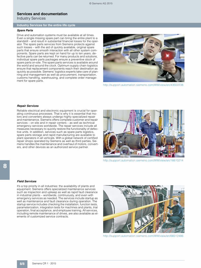
8/8 Siemens CR 1 · 2015
Services and documentationIndustry Services
Industry Services for the entire life cycle
8
Spare Parts
Drive and automation systems must be available at all times. Even a single missing spare part can bring the entire plant to a standstill – and result in substantial financial losses for the oper-ator. The spare parts services from Siemens protects against such losses – with the aid of quickly available, original spare parts that ensure smooth interaction with all other system com-ponents. Spare parts are kept on hand for up to ten years; de-fective parts can be returned. For many products and solutions, individual spare parts packages ensure a preventive stock of spare parts on-site. The spare parts services is available around the world and around the clock. Optimum supply chain logistics ensure that replacement components reach their destination as quickly as possible. Siemens’ logistics experts take care of plan-ning and management as well as procurement, transportation, customs handling, warehousing, and complete order manage-ment for spare parts.
http://support.automation.siemens.com/WW/view/en/43502238
Repair Services
Reliable electrical and electronic equipment is crucial for oper-ating continuous processes. That is why it is essential that mo-tors and converters always undergo highly specialized repair and maintenance. Siemens offers complete customer and repair services – on site and in repair centers – as well as technical emergency services worldwide. The repair services include all measures necessary to quickly restore the functionality of defec-tive units. In addition, services such as spare parts logistics, spare parts storage and rapid manufacturing are available to plant operators in all verticals. With a global network of certified repair shops operated by Siemens as well as third parties, Sie-mens handles the maintenance and overhaul of motors, convert-ers, and other devices as an authorized service partner.
http://support.automation.siemens.com/WW/view/en/16610214
Field Services
It’s a top priority in all industries: the availability of plants and equipment. Siemens offers specialized maintenance services such as inspection and upkeep as well as rapid fault clearance in industrial plants – worldwide, continuously, and even with emergency services as needed. The services include startup as well as maintenance and fault clearance during operation. The startup service includes checking the installation, function tests, parameterization, integration tests for machines and plants, trial operation, final acceptance, and employee training. All services, including remote maintenance of drives, are also available as el-ements of customized service contracts.
http://support.automation.siemens.com/WW/view/en/66012486
© Siemens AG 2015

8/9Siemens CR 1 · 2015
Services and documentationIndustry Services
Industry Services for the entire life cycle
8
Training
Increasingly, up-to-date knowledge is becoming a determining factor in success. One of the key resources of any company is well-trained staff that can make the right decision at the right mo-ment and take full advantage of the potential. With SITRAIN – Training for Industry, Siemens offers comprehensive advanced training programs. The technical training courses convey exper-tise and practical knowledge directly from the manufacturer. SITRAIN covers Siemens’ entire product and system portfolio in the field of automation and drives. Together with the customer, Siemens determines the company’s individual training needs and then develops an advanced training program tailored to the desired requirements. Additional services guarantee that the knowledge of all Siemens partners and their employees is al-ways up-to-date.
http://support.automation.siemens.com/WW/view/en/43514324
Technical Consulting & Engineering Support
The efficiency of plants and processes leads to sustainable eco-nomic success. Individual services from Siemens help save sub-stantial time and money while also guaranteeing maximum safety. Technical consulting covers the selection of products and systems for efficient industrial plants. The services include plan-ning, consulting, and conceptual design as well as product training, application support, and configuration verification – in all phases of a plant’s lifecycle and in all questions related to product safety. Engineering support offers competent assis-tance throughout the entire project, from developing a precise structure for startup to product-specific preparation for imple-mentation as well as support services in areas such as prototype development, testing and acceptance.
http://support.automation.siemens.com/WW/view/en/16605680
Energy & Environmental Services
Efficient energy use and resource conservation – these top sus-tainability concerns pay off – both for the environment and for companies. Siemens offers integrated solutions that unlock all technical and organizational potential for successful environ-mental management. Customized consulting services are aimed at sustainably lowering the cost of energy and environmental protection and thus increasing plant efficiency and availability. The experts provide support in the conceptual design and im-plementation of systematic solutions in energy and environmen-tal management, enabling maximum energy efficiency and opti-mized water consumption throughout the entire company. Improved data transparency makes it possible to identify sav-ings potential, reduce emissions, optimize production pro-cesses, and thereby noticeably cut costs.
http://support.automation.siemens.com/WW/view/en/42350774
© Siemens AG 2015
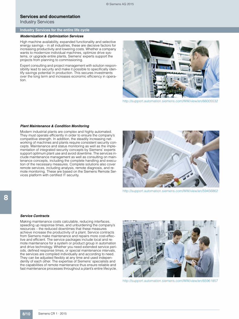
8/10 Siemens CR 1 · 2015
Services and documentationIndustry Services
Industry Services for the entire life cycle
8
Modernization & Optimization Services
High machine availability, expanded functionality and selective energy savings – in all industries, these are decisive factors for increasing productivity and lowering costs. Whether a company wants to modernize individual machines, optimize drive sys-tems, or upgrade entire plants, Siemens’ experts support the projects from planning to commissioning.
Expert consulting and project management with solution respon-sibility lead to security and make it possible to specifically iden-tify savings potential in production. This secures investments over the long term and increases economic efficiency in opera-tion.
http://support.automation.siemens.com/WW/view/en/66005532
Plant Maintenance & Condition Monitoring
Modern industrial plants are complex and highly automated. They must operate efficiently in order to ensure the company’s competitive strength. In addition, the steadily increasing net-working of machines and plants require consistent security con-cepts. Maintenance and status monitoring as well as the imple-mentation of integrated security concepts by Siemens’ experts support optimum plant use and avoid downtime. The services in-clude maintenance management as well as consulting on main-tenance concepts, including the complete handling and execu-tion of the necessary measures. Complete solutions also cover remote services, including analysis, remote diagnosis, and re-mote monitoring. These are based on the Siemens Remote Ser-vices platform with certified IT security.
http://support.automation.siemens.com/WW/view/en/59456862
Service Contracts
Making maintenance costs calculable, reducing interfaces, speeding up response times, and unburdening the company’s resources – the reduced downtimes that these measures achieve increase the productivity of a plant. Service contracts from Siemens make maintenance and repairs more cost-effec-tive and efficient. The service packages include local and re-mote maintenance for a system or product group in automation and drive technology. Whether you need extended service peri-ods, defined response times, or special maintenance intervals, the services are compiled individually and according to need. They can be adjusted flexibly at any time and used indepen-dently of each other. The expertise of Siemens’ specialists and the capabilities of remote maintenance thus ensure reliable and fast maintenance processes throughout a plant’s entire lifecycle.
http://support.automation.siemens.com/WW/view/en/65961857
© Siemens AG 2015

8/11Siemens CR 1 · 2015
8
Services and documentationApplications
■ Overview
Our understanding of an application is the customer-specific so-lution of an automation task based on standard hardware and software components. In this respect, industry knowledge and technological expertise are just as important as expert knowl-edge about how our products and systems work. We are setting ourselves this challenge with more than 160 application engi-neers at 20 locations in 13 countries.
Application centers
We currently have application centers in:• Germany: Head Office Erlangen and 6 German regions,
e.g. in Munich, Nuremberg, Stuttgart, Mannheim, Frankfurt, Chemnitz, Cologne, Bielefeld, Bremen, Hanover, Hamburg
• Italy: Bologna, Milan• USA: Atlanta• China: Beijing, Shanghai• France: Paris• Turkey: Istanbul• India: Mumbai• Switzerland: Zurich• United Kingdom: Manchester• Brazil: Sao Paulo• Japan: Tokyo, Osaka• The Netherlands: The Hague• Denmark: Ballerup
These application centers specialize in the use of SIMOTION/SINAMICS. You can therefore rely on automation and drive spe-cialists for implementing successful applications. By involving your personnel at an early stage in the process, we can provide a solid basis for rapid knowledge transfer, maintenance and fur-ther development of your automation solution.
Advice on applications and implementation
We offer a variety of consultation services to help you find the op-timum solution for the SIMOTION/SINAMICS application you want to implement.
The quotation phase includes:• Clarification of technical questions• Discussion of machine concepts and customer-specific
solutions• Selection of suitable technology and• Suggestions for implementation
A technical feasibility study is also performed at the outset. In this way, difficult points of the application can be identified and solved early on. We can also configure and implement your ap-plication as a complete solution including control cabinet from a single source.
During the implementation phase a number of proven standards can be applied. This saves engineering costs.
The system can be commissioned by experienced, competent personnel, if required. This saves time and trouble.
If servicing is required, we can support you on site or via tele-service. For further information about servicing, please see "Service & Support".
On-site application training
Training for the implemented applications can also be organized and carried out on site. This training for machine manufacturers and their customers does not deal with individual products, but the entire hardware and software system (for example, automa-tion, drives and visualization).
From an initial concept to successful installation and commis-sioning: We can provide complete support for SIMOTION/SINAMICS! Contact your Siemens representative.
For additional information, refer to:
https://support.industry.siemens.com/cs/
→ Applications Examples → Cranes
© Siemens AG 2015

8/12 Siemens CR 1 · 2015
8
Services and documentationCrane-specific training
SITRAIN
■ Overview
Faster and more applicable know-how: Hands-on training from the manufacturer
Siemens Industry Training provides you with comprehensive support in solving your tasks.
Training by the market leader in the industry enables you to make independent decisions with confidence. Especially where the optimum and efficient use of products and plants are con-cerned. You can eliminate deficiencies in existing plants, and exclude expensive faulty planning right from the beginning.
First-class know-how directly pays for itself: In shorter commis-sioning times, high-quality end products, faster troubleshooting and reduced downtimes. In other words, increased profits and lower costs.
Achieve more with Siemens Industry Training• Shorter times for commissioning, maintenance and servicing• Optimized production operations • Reliable configuration and commissioning• Minimization of plant downtimes• Flexible plant adaptation to market requirements • Compliance with quality standards in production • Increased employee satisfaction and motivation • Shorter familiarization times following changes in technology
and staff
Siemens Industry Training is characterized by
Top trainers
Our trainers are skilled teachers with direct practical experience. Course developers have close contact with product develop-ment, and directly pass on their knowledge to the trainers.
Practical relevance
The practical experience of our trainers enables them to teach theory effectively. We also place the highest emphasis on prac-tical exercises, which make up to half of the course time. You can therefore immediately implement your new knowledge in prac-tice. We train you methodically on state-of-the-art training equip-ment. This training approach will give you all the confidence you need.
Wide variety
With a total of about 300 local attendance courses, we train the complete range of products from Siemens Industry as well as in-teraction of the products in systems.
Customized training
We are only a short distance away. You can find us at more than 50 locations in Germany, and in 62 countries worldwide. You wish to have individual training instead of one of our 300 courses? Our solution: We will provide a program tailored ex-actly to your personal requirements. Training can be carried out in our Training Centers or at your company location.
The right mixture: Blended learning
"Blended learning" is a combination of various training media and sequences. For example, a participant based course in a Training Center can be optimally supplemented by a self-teach program as preparation or follow-up. Additional effect: Reduced traveling costs and periods of absence.
■ More information
Contact
Visit our Internet site at:http://www.siemens.nl/training/cranes
or let us advise you personally. You can request our latest train-ing catalog from:
Siemens Training NL
phone: +31 (70) 333-3900
e-mail: [email protected]
© Siemens AG 2015

8/13Siemens CR 1 · 2015
8
Services and documentationCrane-specific training
SIMOCRANE course overview
■ Overview
Cranes training courses
Training solution partner
3 days
Safety StandardsFactory Automation
2 days
SIMOCRANE Sway ControlCommissioning
10 daysOn special request
G_CR01_EN_00386
SIMOCRANEEngineering
1 day
Electronic Straight-run Controller
SIMOCRANE CeNIT
SIMOTION
Sway Control
Safety
5 days
MaintanceSIMOCRANE,SIMOTION/SINAMICS
Practical crane installation
SIMOCRANEMaintenance
2 daysCR-SI
3 daysCR-DBT
Basics Crane course
SIMOCRANECommissioning
5 daysCR-BASICS
SINAMICS Safety integrated for Cranes
Basic Motions and SwayControl
Drive-Based Technology
Crane Physics and Drive Sizing
G_CR01_EN_00387
Harbor cranes
2 daysCR-SI
SINAMICS Safety integrated for Cranes
3 daysCR-STC
SIMOCRANE Technology Customised
4 hours
Exam: Crane Physicsand Drive Sizing
1 hour
Exam: Assessment
2 daysCR-SI
3 daysCR-DBT
Basics Crane course
Industry cranes
5 daysCR-BASICS
SINAMICS Safety integrated for Cranes
Basic Motions and SwayControl
Drive-Based Technology
Crane Physics and Drive Sizing
© Siemens AG 2015

8/14 Siemens CR 1 · 2015
8
Services and documentationSpares on Web
■ Overview
Spares on Web – Identification of spare parts on the Internet
Spares on Web is a web-based tool for identifying spare parts. After you have entered the Article No. and serial number, the spare parts available for the relevant unit are displayed.
www.siemens.com/sow
© Siemens AG 2015

8/15Siemens CR 1 · 2015
8
Services and documentationMy Documentation Manager
■ Overview
My Documentation Manager – Customizing information
My Documentation Manager offers all Motion Control customers an innovation with extended usability: Machine manufacturers and end customers are not only able to assemble their own cus-tomized technical documents for a specific product or system, they can also generate complete libraries with individually con-figured contents. The content that matches your topic can be found from the full range of documentation stored under Service & Support using the operator interface and assembled using drag & drop into application-based libraries, generated and even combined with your own documentation. The self-gen-erated collections can be saved in the commonly used RTF and PDF formats or even in XML format.
You must register for configuring and generating/managing (the existing login can be used, e.g. Industry Mall www.siemens.com/industrymall
■ Benefits
• DisplayView, print or download standard documents or personalized documents
• ConfigureTransfer standard documents or parts of them to personalized documents
• Generate/ManageProduce and manage personalized documents in the formats PDF, RTF or XML
■ Design
My Documentation Manager is the web-based system to gener-ate personalized documentation based on standard documents. It is part of the Service & Support Portal.
Search in the Service & Support portal
Document in My Documentation Manager
■ Function
Opening My Documentation Manager
My Documentation Manager opens in two ways• Search in the Service & Support portal
www.siemens.com/automation/service&supportThe appropriate manuals are designated by "configurable".My Documentation Manager opens by clicking on "Displayand configure". The selected document is displayed as thecurrent document.
• Using the direct link from the Service & Support portalwww.automation.siemens.com/docconf/After logon/registration, the online help is displayed as currentdocument.
■ More information
You can find more information on the Internet atwww.siemens.com/mdm
© Siemens AG 2015
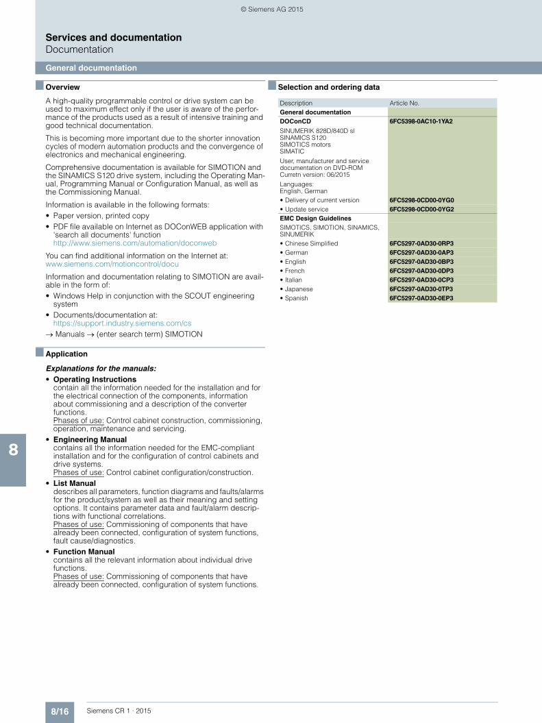
8/16 Siemens CR 1 · 2015
8
Services and documentationDocumentation
General documentation
■ Overview
A high-quality programmable control or drive system can be used to maximum effect only if the user is aware of the perfor-mance of the products used as a result of intensive training and good technical documentation.
This is becoming more important due to the shorter innovation cycles of modern automation products and the convergence of electronics and mechanical engineering.
Comprehensive documentation is available for SIMOTION and the SINAMICS S120 drive system, including the Operating Man-ual, Programming Manual or Configuration Manual, as well as the Commissioning Manual.
Information is available in the following formats:• Paper version, printed copy• PDF file available on Internet as DOConWEB application with
'search all documents' function http://www.siemens.com/automation/doconweb
You can find additional information on the Internet at: www.siemens.com/motioncontrol/docu
Information and documentation relating to SIMOTION are avail-able in the form of:• Windows Help in conjunction with the SCOUT engineering
system• Documents/documentation at:
https://support.industry.siemens.com/cs→ Manuals → (enter search term) SIMOTION
■ Application
Explanations for the manuals:• Operating Instructions
contain all the information needed for the installation and for the electrical connection of the components, information about commissioning and a description of the converter functions. Phases of use: Control cabinet construction, commissioning, operation, maintenance and servicing.
• Engineering Manualcontains all the information needed for the EMC-compliant installation and for the configuration of control cabinets and drive systems. Phases of use: Control cabinet configuration/construction.
• List Manualdescribes all parameters, function diagrams and faults/alarms for the product/system as well as their meaning and setting options. It contains parameter data and fault/alarm descrip-tions with functional correlations.Phases of use: Commissioning of components that have already been connected, configuration of system functions, fault cause/diagnostics.
• Function Manualcontains all the relevant information about individual drive functions. Phases of use: Commissioning of components that have already been connected, configuration of system functions.
■ Selection and ordering data
Description Article No.General documentationDOConCD
SINUMERIK 828D/840D slSINAMICS S120SIMOTICS motorsSIMATIC
User, manufacturer and servicedocumentation on DVD-ROMCurretn version: 06/2015
Languages: English, German
6FC5398-0AC10-1YA2
• Delivery of current version 6FC5298-0CD00-0YG0• Update service 6FC5298-0CD00-0YG2EMC Design GuidelinesSIMOTICS, SIMOTION, SINAMICS, SINUMERIK• Chinese Simplified 6FC5297-0AD30-0RP3• German 6FC5297-0AD30-0AP3• English 6FC5297-0AD30-0BP3• French 6FC5297-0AD30-0DP3• Italian 6FC5297-0AD30-0CP3• Japanese 6FC5297-0AD30-0TP3• Spanish 6FC5297-0AD30-0EP3
© Siemens AG 2015

8/17Siemens CR 1 · 2015
8
Services and documentationCAD CREATOR
■ Overview
CAD CREATOR – Dimensional drawing and 2D/3D CAD generator
Thanks to the user-friendly operator interface of the CAD CREATOR, it is easy to configure controls, drives and motors. With the support of the CAD CREATOR, product-specific dimension drawings and 2D/3D CAD models can be created quickly. The CAD CREATOR assists the machine manufacturer's designers, drafting engineers and project engineers.
■ Selection and ordering data
■ More information
The CAD CREATOR is available on DVD-ROM and as an Internet application.
Additional information is available on the Internet at www.siemens.com/cadcreator
■ Benefits
• Provision of dimension drawings as 2D/3D CAD models in mm and inches
• Display of 2D/3D CAD models and dimension drawings on integrated viewers
• With the online version, 3D models and dimension drawings can also be displayed in the form of a downloadable PDF
• Support for all general geometry interfaces STEP, IGES, Parasolid, SAT, VDA, and for special interfaces such as Ideas, NX, Solid Edge, Pro/Engineer, Autocad, Inventor, Mechanical Desktop, Catia and Solidworks
• Multi-language operator interface in English, French, German, Italian and Spanish, and direct Help (English, German)
• Dimension drawings and 2D/3D CAD models for:• Motors
- 1FT6/1FT7/1FK7 synchronous motors- 1FE1 built-in synchronous motors- 1FW3 torque motors- 1FW6 built-in torque motors- 1FT6/1FT7/1FK7 geared motors- 1PH8 synchronous/asynchronous motors- 1PH7/1PH4/1PL6/1PM4/1PM6 asynchronous motors- 2SP1 motor spindles- 1FN3, 1FN6 linear motors
• SINAMICS S110, SINAMICS S120- Control Units- Power Modules (Blocksize/Chassis/Combi)- Line Modules (Booksize/Chassis)- Line-side components- Motor Modules (Booksize/Chassis)- DC link components- Supplementary system components- Load-side power components- Encoder system connection- Connection system MOTION-CONNECT
• SINUMERIK- CNC controls- Operator components for CNC controls
• SIMOTION- SIMOTION D- SIMOTION C
The CAD CREATOR offers a variety of options for configuring, but also different methods for searching for a product:• According to Article No.• According to technical description
After successful configuration of the product, the dimensional drawings and models are displayed with the integrated viewers and made available for export.
Description Article No.CAD CREATOR 6SL3075-0AA00-0AG0Dimensional drawing and 2D/3D CAD generator on DVD-ROMEnglish, French, German, Italian, Spanish
© Siemens AG 2015

8/18 Siemens CR 1 · 2015
8
Services and documentation
Notes
© Siemens AG 2015
Siemens CR 1 · 2015
99/2 SIMOCRANE symbols9/2 Functions of the Crane Management System9/3 User groups9/4 Installation locations9/5 Crane drives and drive axis9/6 Extended technological functions and
products9/8 Crane types9/9 Subsystems and components
9/10 Approvals
9/11 Software Licenses
9/13 Metall surcharges
9/16 Conditions of sale and delivery
Appendix
© Siemens AG 2015

9/2 Siemens CR 1 · 2015
9
AppendixSIMOCRANE symbols
Functions of the Crane Management System
■ Overview
Function Symbol Description of functions
Status display • Graphical visualization of crane, components and subsystems
• Settings of operating parameters for crane operation
Condition monitoring • Recording of highly dynamic operating variables
• Monitoring of limit values
Error diagnostics • Alarm/event reporting with archiving
• Calling up contextual information
• Error analysis functions
Measured value acquisition • Long-term recording of operating values
• Graphical or tabular representation and evaluation
Operating data acquisition and reporting
• Acquisition of operating data, operating hours and counter values
• Reporting
Reference information • Fast access to plant-related sources of information
Maintenance functions • Maintenance messages and instructions
© Siemens AG 2015
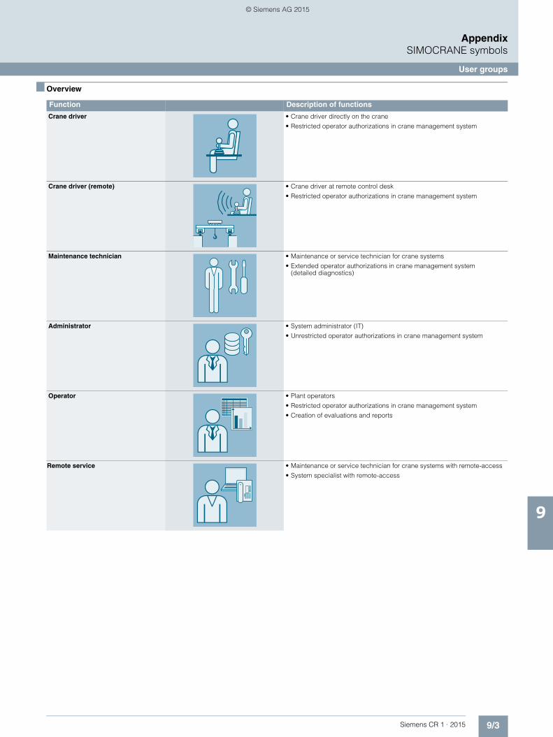
9/3Siemens CR 1 · 2015
9
AppendixSIMOCRANE symbols
User groups
■ Overview
Function Description of functions
Crane driver • Crane driver directly on the crane
• Restricted operator authorizations in crane management system
Crane driver (remote) • Crane driver at remote control desk
• Restricted operator authorizations in crane management system
Maintenance technician • Maintenance or service technician for crane systems
• Extended operator authorizations in crane management system (detailed diagnostics)
Administrator • System administrator (IT)
• Unrestricted operator authorizations in crane management system
Operator • Plant operators
• Restricted operator authorizations in crane management system
• Creation of evaluations and reports
Remote service • Maintenance or service technician for crane systems with remote-access
• System specialist with remote-access
© Siemens AG 2015

9/4 Siemens CR 1 · 2015
9
AppendixSIMOCRANE symbols
Installation locations
■ Overview
Function Symbol Description of functions
Electrical room • Installation location for the complete drive and control technology on a crane
Crane driver cabin • Moveable or permanently installed crane driver cabin
Maintenance building • Building/location of service and maintenance technician at a terminal
Administration center • Terminal administration
• Central control room with logistics systems
• Central server landscape and IT administration
© Siemens AG 2015

9/5Siemens CR 1 · 2015
9
AppendixSIMOCRANE symbols
Crane drives and drive axis
■ Overview
Function Symbol Description of functions
Hoist • Hoisting axis for container cranes
Gantry • Gantry axis for cranes of different types
Trolley • Traversing axis for the trolley of cranes of different types
Slewing gear • Slewing gear axis for slewing luffing cranes and similar types
Grab • Holding and closing gear for grab cranes
Boom • Drive axis for the crane boom-hoist for STS or ship unloading cranes
AGV • Automatic guided vehicle
© Siemens AG 2015

9/6 Siemens CR 1 · 2015
9
AppendixSIMOCRANE symbols
Extended technological functions and products
■ Overview
Function Symbol Description of functions
SIMOCRANE ECO Technology • Fuel saving power management software for combustion engine and alternator power machinery
SIMOCRANE Sway Control Systems • Automatic sway control for cranes of different types
SIMOCRANE Truck Positioning • Positioning system for trucks hitched to trailers in container terminals
SIMOCRANE CMS • Crane management system
• Status display
• Diagnostics
• Information
Position control • Automatic picking up of a load (container) from a truck
• Automatic lowering of a load (container) onto a truck
• Application-specific function with the use of SIMOCRANE products Truck Positioning and the SIMOCRANE Sway Control System
Collision Detection Stack • Collision protection in the stacking area of container terminals
Collision Detection ASC • Collision protection for automatic stacking cranes at container-terminals
Collision Detection STS • Collision protection crane – ship with STS cranes
• Avoidance of damage to crane or ship
© Siemens AG 2015

9/7Siemens CR 1 · 2015
9
■ Overview (continued)
AppendixSIMOCRANE symbols
Extended technological functions and products
Automatic travel • Automatic or semi-automatic loading and unloading for container cranes
• This function is derived from a function of "SIMOCRANE Sway Control Systems"
On-the-fly unloading • On-the-fly unloading of bulk material to grab cranes
Skew control • Automatic control of the load angle on a ship to shore crane (STS)
• The presence of the corresponding mechanical components is a pre-req-uisite for this function
• This function is derived from a function of "SIMOCRANE Sway Control Systems"
Position control (stack) • Automatic positioning
Profile scanning • Automatic detection of the height profile of a container stack in the "stack"
• Prerequisite for fully automatic crane operation in the stacking area and for avoiding collisions
Bay scanning • Automatic acquisition of the height profile of a container stack on the ship
• Pre-requisite for automatic mode in conjunction with SIMOCRANE Sway Control Systems
Remote access or remote control of stacking
• Remote access of information of the stacking cranes from any PC in the terminal
• Remote access web based
• Remote control of the crane from control room
Remote access to ship-to-shore cranes
• Remote access of information of the STS cranes from any PC in the terminal
• Remote access web based
Function Symbol Description of functions
© Siemens AG 2015

9/8 Siemens CR 1 · 2015
9
AppendixSIMOCRANE symbols
Crane types
■ Overview
Function Symbol Description of functions
Ladle crane • Ladle crane in steelworks
Straddle carrier • Mobile transport crane in container terminals
RTG (ECO RTG) • Rubber Tired Gantry
• Mobile, rubber-tired stacking crane
• ECO RTG
• Energy-efficient and diesel-powered RTG with hybrid drive system and reload function
GSU • Grab Ship Unloader
• Grab ship unloading crane for handling bulk material in the harbor area
STS • Ship To Shore crane
• Container handling in the harbor area
• Cargo handling between ship and terminal
RMG • Rail Mounted Gantry
• Rail-mounted stacking crane in the container terminal
• This type of crane is frequently used as an automated stacking crane (ASC)
SLC • Slewing luffing crane
© Siemens AG 2015

9/9Siemens CR 1 · 2015
8
AppendixSIMOCRANE symbols
Subsystems and components
■ Overview
Function Symbol Description of functions
Converter • Frequency converter for three-phase motors
Motor • Motor for the hoisting gear, gantry, trolley, slewing gear etc.
Master switch • Control instrument at crane driver's seat
Cable trailing • Trailing cable system for moving crane components
• Example: Container crane trolley
Cable drum • Cable drum for the main supply cable of electri-cally supplied cranes
Brake • Brakes for the different drive axes of a crane
Refurbishment • Service for the modernization and conversion of older crane systems
CeSAR • Controller-supported Sway Control System
© Siemens AG 2015

9/10 Siemens CR 1 · 2015
9
AppendixApprovals
■ Overview
Many of the products in this catalog comply with UL or CSA requirements and are labeled with the corresponding ap-proval designation.
All of the approvals, certificates, declarations of conformity, test certificates, e.g. CE, UL, Safety Integrated etc. have been per-formed with the associated system components as they are de-scribed in the catalogs and configuration manuals.
The certificates are only valid if the products are used with the described system components, are installed according to the in-stallation guidelines and are used for their intended purpose. In other cases, the vendor of these products is responsible for ar-ranging that new certificates are issued.
UL: Underwriters Laboratories (independent public testing institution in North America)
Test symbol:• UL for end products, tested by UL in accordance with the UL
standard• cUL for end products, tested by UL in accordance with the
CSA standard• cULus for end products, tested by UL in accordance with the
UL and CSA standards• UR for mounting parts in end products, tested by UL in accor-
dance with the UL standard• cUR for mounting parts in end products, tested by UL in
accordance with the CSA standard• cURus for mounting parts in end products, tested by UL in
accordance with the UL and CSA standards
Test standards:• SIMOTION: Standard UL 508• SINAMICS: Standard UL 508C• Motors: Standard UL 547
Product category/file No.:• SIMOTION: E164110• SINAMICS: E192450• Motors: E93429
TUV: TUV Rheinland of North America Inc. Independent pub-lic testing institution in North America National recognized testing laboratory (NRTL)
Test symbol:• cTUVus Tested by TUV in accordance with the UL and CSA
standards
CSA: Canadian Standard Association Independent public testing institution in Canada
Test symbol:• CSA Tested by CSA in accordance with the CSA standard
Test standard:• Standard CAN/CSA-C22.2/No. 0-M91/No. 14-05/No.
142-M1987
G_N
C01
_XX
_004
23
© Siemens AG 2015

9/11Siemens CR 1 · 2015
AppendixSoftware Licenses
9
■ Overview
Software typesSoftware requiring a license is categorized into types.The following software types have been defined:• Engineering software• Runtime software
Engineering softwareThis includes all software products for creating (engineering) user software, e.g. for configuring, programming, parameteriz-ing, testing, commissioning or servicing. Data generated with engineering software and executable programs can be duplicated for your own use or for use by third-parties free-of-charge.
Runtime softwareThis includes all software products required for plant/machine operation, e.g. operating system, basic system, system expan-sions, drivers, etc.The duplication of the runtime software and executable pro-grams created with the runtime software for your own use or for use by third-parties is subject to a charge. You can find information about license fees according to use in the ordering data (e.g. in the catalog). Examples of categories of use include per CPU, per installation, per channel, per instance, per axis, per control loop, per variable, etc.Information about extended rights of use for parameterization/configuration tools supplied as integral components of the scope of delivery can be found in the readme file supplied with the relevant product(s).
License typesSiemens Industry Automation & Drive Technologies offers vari-ous types of software license:• Floating license• Single license• Rental license• Rental floating license• Trial license• Demo license• Demo floating license
Floating licenseThe software may be installed for internal use on any number of devices by the licensee. Only the concurrent user is licensed. The concurrent user is the person using the program. Use begins when the software is started. A license is required for each concurrent user.
Single licenseUnlike the floating license, a single license permits only one installation of the software per license. The type of use licensed is specified in the ordering data and in the Certificate of License (CoL). Types of use include for example per instance, per axis, per channel, etc. One single license is required for each type of use defined.
Rental licenseA rental license supports the "sporadic use" of engineering software. Once the license key has been installed, the software can be used for a specific period of time (the operating hours do not have to be consecutive). One license is required for each installation of the software.
Rental floating licenseThe rental floating license corresponds to the rental license, except that a license is not required for each installation of the software. Rather, one license is required per object (for example, user or device).
Trial licenseA trial license supports "short-term use" of the software in a non-productive context, e.g. for testing and evaluation purposes. It can be transferred to another license.
Demo licenseThe demo license support the "sporadic use" of engineering soft-ware in a non-productive context, for example, use for testing and evaluation purposes. It can be transferred to another license. After the installation of the license key, the software can be operated for a specific period of time, whereby usage can be interrupted as often as required.One license is required per installation of the software.
Demo floating licenseThe demo floating license corresponds to the demo license, except that a license is not required for each installation of the software. Rather, one license is required per object (for example, user or device).
Certificate of license (CoL)The CoL is the licensee's proof that the use of the software has been licensed by Siemens. A CoL is required for every type of use and must be kept in a safe place.
DowngradingThe licensee is permitted to use the software or an earlier ver-sion/release of the software, provided that the licensee owns such a version/release and its use is technically feasible.
Delivery versionsSoftware is constantly being updated.The following delivery versions• PowerPack• Upgradecan be used to access updates.Existing bug fixes are supplied with the ServicePack version.
PowerPackPowerPacks can be used to upgrade to more powerful software.The licensee receives a new license agreement and CoL (Certificate of License) with the PowerPack. This CoL, together with the CoL for the original product, proves that the new soft-ware is licensed. A separate PowerPack must be purchased for each original license of the software to be replaced.
UpgradeAn upgrade permits the use of a new version of the software on the condition that a license for a previous version of the product is already held.The licensee receives a new license agreement and CoL with the upgrade. This CoL, together with the CoL for the previous product, proves that the new version is licensed.A separate upgrade must be purchased for each original license of the software to be upgraded.
© Siemens AG 2015

9/12 Siemens CR 1 · 2015
AppendixSoftware Licenses
9
■ Overview
ServicePackServicePacks are used to debug existing products. ServicePacks may be duplicated for use as prescribed accord-ing to the number of existing original licenses.
License keySiemens Industry Automation & Drive Technologies supplies software products with and without license keys.The license key serves as an electronic license stamp and is also the "switch" for activating the software (floating license, rental license, etc.).The complete installation of software products requiring license keys includes the program to be licensed (the software) and the license key (which represents the license).
Software Update Service (SUS)As part of the SUS contract, all software updates for the respec-tive product are made available to you free of charge for a period of one year from the invoice date. The contract will automatically be extended for one year if it is not canceled three months before it expires.The possession of the current version of the respective software is a basic condition for entering into an SUS contract.
You can download explanations concerning license conditions fromwww.siemens.com/automation/salesmaterial-as/catalog/en/terms_of_trade_en.pdf
© Siemens AG 2015

9/13Siemens CR 1 · 2015
AppendixMetal surcharges
9
■ Explanation of the raw material/metal surcharges1 2 3 4
Surcharge calculationTo compensate for variations in the price of the raw materials silver, copper, aluminum, lead, gold, dysprosium2) and/or neodym2), surcharges are calculated on a daily basis using the so-called metal factor for products containing these raw materials. A surcharge for the respective raw material is calcu-lated as a supplement to the price of a product if the basic official price of the raw material in question is exceeded.The surcharges are calculated in accordance with the following criteria:• Basic official price of the raw material
Basic official price from the day prior to receipt of the order or prior to release order (daily price) for3)
- Silver (sales price, processed) - Gold (sales price, processed)
and for4)
- Copper (lower DEL notation + 1 %)- Aluminum (aluminum in cables) - Lead (lead in cables)
• Metal factor of the productsCertain products are displayed with a metal factor. The metal factor determines the official price (for those raw materials concerned) as of which the metal surcharges are applied and the calculation method used (weight or percentage method). An exact explanation is given below.
Structure of the metal factor
The metal factor consists of several digits; the first digit indicates whether the percentage method of calculation refers to the list price or a possible discounted price (customer net price) (L = list price / N = customer net price).
The remaining digits indicate the method of calculation used for the respective raw material. If no surcharge is added for a raw material, a "-" is used.
Weight method
The weight method uses the basic official price, the daily price and the raw material weight. In order to calculate the surcharge, the basic official price must be subtracted from the daily price. The difference is then multiplied by the raw material weight.
The basic official price can be found in the table below using the number (1 to 9) of the respective digit of the metal factor. The raw material weight can be found in the respective product descrip-tions.
Percentage method
Use of the percentage method is indicated by the letters A-Z at the respective digit of the metal factor.
The surcharge is increased - dependent on the deviation of the daily price compared with the basic official price - using the per-centage method in "steps" and consequently offers surcharges that remain constant within the framework of this "step range". A higher percentage rate is charged for each new step. The res-pective percentage level can be found in the table below.
Metal factor examples
1. Refer to the separate explanation on the next page regarding the raw materials dysprosium and neodym (= rare earths).2. For a different method of calculation, refer to the separate explanation for these raw materials on the next page.3. Source: Umicore, Hanau (www.metalsmanagement.umicore.com).4. Source: German Trade Association for Cables and Conductors (www.kabelverband.org).
1st digit List or customer net price using the percentage method
2nd digit for silver (AG)
3rd digit for copper (CU)
4th digit for aluminum (AL)
5th digit for lead (PB)
6th digit for gold (AU)
7th digit for dysprosium (Dy)2)
8th digit for neodym (Nd)2)
L E A – – – – –
Basis for % surcharge: List price
Silver Basis 150 €, Step 50 €, 0.5 %
Copper Basis 150 €, Step 50 €, 0.1 %
No surcharge for aluminum
No surcharge for lead
No surcharge for gold
No surcharge for dysprosium
No surcharge for neodym
N – A 6 – – – –
Basis for % surcharge: Customer net price
No surcharge for silver
Copper Basis 150 €, Step 50 €, 0.1 %
Aluminum acc. to weight, basic offic. price 225 €
No surcharge for lead
No surcharge for gold
No surcharge for dysprosium
No surcharge for neodym
– – 3 – – – – –
No basis necessary
No surcharge for silver
Copper acc. to weight, basic official price 150 €
No surcharge for aluminum
No surcharge for lead
No surcharge for gold
No surcharge for dysprosium
No surcharge for neodym
© Siemens AG 2015

9/14 Siemens CR 1 · 2015
AppendixMetal surcharges
9
■ Explanation of the raw material/metal surcharges for dysprosium and neodym (rare earths)1 2
Surcharge calculationTo compensate for variations in the price of the raw materials silver1), copper1), aluminum1), lead1), gold1), dysprosium and/or neodym, surcharges are calculated on a daily basis using the so-called metal factor for products containing these raw materials. The surcharge for dysprosium and neodym is calcu-lated as a supplement to the price of a product if the basic official price of the raw material in question is exceeded.The surcharge is calculated in accordance with the following criteria:• Basic official price of the raw material2)
Three-month basic average price (see below) in the period before the quarter in which the order was received or the re-lease order took place (= average official price) for- dysprosium (Dy metal, 99 % min. FOB China; USD/kg)- neodym (Nd metal, 99 % min. FOB China; USD/kg)
• Metal factor of the productsCertain products are displayed with a metal factor. The metal factor indicates (for those raw materials concerned) the basic official price as of which the surcharges for dysprosium and neodym are calculated using the weight method. An exact ex-planation of the metal factor is given below.
Three-month average price
The prices of rare earths vary according to the foreign currency, and there is no freely accessible stock exchange listing. This makes it more difficult for all parties involved to monitor changes in price. In order to avoid continuous adjustment of the surchar-ges, but to still ensure fair, transparent pricing, an average price is calculated over a three-month period using the average monthly foreign exchange rate from USD to EUR (source: Euro-pean Central Bank). Since not all facts are immediately available at the start of each month, a one-month buffer is allowed before the new average price applies.
Examples of calculation of the average official price:
Structure of the metal factor
The metal factor consists of several digits; the first digit is not re-levant to the calculation of dysprosium and neodym.
The remaining digits indicate the method of calculation used for the respective raw material. If no surcharge is added for a raw material, a "-" is used.
Weight method
The weight method uses the basic official price, the average price and the raw material weight. In order to calculate the surcharge, the basic official price must be subtracted from the average price. The difference is then multiplied by the raw ma-terial weight.
The basic official price can be found in the table below using the number (1 to 9) of the respective digit of the metal factor. Your Sales contact can inform you of the raw material weight.
Metal factor examples
1. For a different method of calculation, refer to the separate explanation for these raw materials on the previous page.2. Source: Asian Metal Ltd (www.asianmetal.com)
Period for calculation of the average price:
Period during which the order/release order is effected and the average price applies:
Sep 2012 - Nov 2012 Q1 in 2013 (Jan - Mar)
Dec 2012 - Feb 2013 Q2 in 2013 (Apr - Jun)
Mar 2013 - May 2013 Q3 in 2013 (Jul - Sep)
Jun 2013 - Aug 2013 Q4 in 2013 (Oct - Dec)
1st digit List or customer net price using the percentage method
2nd digit for silver (AG)1)
3rd digit for copper (CU)1)
4th digit for aluminum (AL)1)
5th digit for lead (PB)1)
6th digit for gold (AU)1)
7th digit for dysprosium (Dy)
8th digit for neodym (Nd)
– – – – – – 7 1
No basis necessary
No surcharge for silver
No surcharge for copper
No surcharge for aluminum
No surcharge for lead
No surcharge for gold
Dysprosium acc. to weight, basic official price 300 €
Neodym acc. to weight, basic official price 50 €
© Siemens AG 2015

9/15Siemens CR 1 · 2015
AppendixMetal surcharges
9
■ Values of the metal factor
Percentage method
Basic official pricein €
Step range in €
% surcharge1st step
% surcharge2nd step
% surcharge3rd step
% surcharge4th step
% surcharge
per additio-nal stepPrice in € Price in € Price in € Price in €
150.01 - 200.00 200.01 - 250.00 250.01 - 300.00 300.01 - 350.00
A 150 50 0.1 0.2 0.3 0.4 0.1
B 150 50 0.2 0.4 0.6 0.8 0.2
C 150 50 0.3 0.6 0.9 1.2 0.3
D 150 50 0.4 0.8 1.2 1.6 0.4
E 150 50 0.5 1.0 1.5 2.0 0.5
F 150 50 0.6 1.2 1.8 2.4 0.6
G 150 50 1.0 2.0 3.0 4.0 1.0
H 150 50 1.2 2.4 3.6 4.8 1.2
I 150 50 1.6 3.2 4.8 6.4 1.6
J 150 50 1.8 3.6 5.4 7.2 1.8
175.01 - 225.00 225.01 - 275.00 275.01 - 325.00 325.01 - 375.00
O 175 50 0.1 0.2 0.3 0.4 0.1
P 175 50 0.2 0.4 0.6 0.8 0.2
R 175 50 0.5 1.0 1.5 2.0 0.5
225.01 - 275.00 275.01 - 325.00 325.01 - 375.00 375.01 - 425.00
S 225 50 0.2 0.4 0.6 0.8 0.2
U 225 50 1.0 2.0 3.0 4.0 1.0
V 225 50 1.0 1.5 2.0 3.0 1.0
W 225 50 1.2 2.5 3.5 4.5 1.0
150.01 - 175.00 175.01 - 200.00 200.01 - 225.00 225.01 - 250.00
Y 150 25 0.3 0.6 0.9 1.2 0.3
400.01 - 425.00 425.01 - 450.00 450.01 - 475.00 475.01 - 500.00
Z 400 25 0.1 0.2 0.3 0.4 0.1
Price basis (1st digit)
L Calculation based on the list price
N Calculation based on the customer net price (discounted list price)
Weight method
Basic official price in €
1 50
Calculation based on raw material weight
2 100
3 150
4 175
5 200
6 225
7 300
8 400
9 555
Miscellane-ous
- No metal surcharge
© Siemens AG 2015

9/16 Siemens CR 1 · 2015
AppendixConditions of sale and delivery
9
■ 1. General Provisions
By using this catalog you can acquire hardware and software products described therein from Siemens AG subject to the following Terms and Conditions of Sale and Delivery (hereinafter referred to as "T&C"). Please note that the scope, the quality and the conditions for supplies and services, including software products, by any Siemens entity having a registered office outside Germany, shall be subject exclusively to the General Terms and Conditions of the respective Siemens entity. The following T&C apply exclusively for orders placed with Siemens Aktiengesellschaft, Germany.
1.1 For customers with a seat or registered office in Ger-manyFor customers with a seat or registered office in Germany, the following applies subordinate to the T&C:• the "General Terms of Payment"1) and,• for software products, the "General License Conditions for
Software Products for Automation and Drives for Customers with a Seat or Registered Office in Germany"1) and,
• for other supplies and services, the "General Conditions for the Supply of Products and Services of the Electrical and Elec-tronics Industry"1).
1.2 For customers with a seat or registered office outside GermanyFor customers with a seat or registered office outside Germany, the following applies subordinate to the T&C:• the "General Terms of Payment"1) and,• for software products, the "General License Conditions for
Software Products for Automation and Drives for Customers with a Seat or Registered Office outside of Germany"1) and
• for other supplies and/or services, the "General Conditions for Supplies of Siemens Industry for Customers with a Seat or Re-gistered Office outside of Germany"1).
■ 2. Prices
The prices are in € (Euro) ex point of delivery, exclusive of packaging.The sales tax (value added tax) is not included in the prices. It shall be charged separately at the respective rate according to the applicable statutory legal regulations.Prices are subject to change without prior notice. We will charget the prices valid at the time of delivery.To compensate for variations in the price of raw materials (e.g. silver, copper, aluminum, lead, gold, dysprosium and neodym), surcharges are calculated on a daily basis using the so-called metal factor for products containing these raw materials. A surcharge for the respective raw material is calculated as a supplement to the price of a product if the basic official price of the raw material in question is exceeded.The metal factor of a product indicates the basic official price (for those raw materials concerned) as of which the surcharges on the price of the product are applied, and with what method of calculation. An exact explanation of the metal factor can be downloaded at:www.siemens.com/automation/salesmaterial-as/catalog/en/ terms_of_trade_en.pdfTo calculate the surcharge (except in the cases of dysprosium and neodym), the official price from the day prior to that on which the order was received or the release order was effected is used.To calculate the surcharge applicable to dysprosium and neodym ("rare earths"), the corresponding three-month basic average price in the quarter prior to that in which the order was received or the release order was effected is used with a one-month buffer (details on the calculation can be found in the explanation of the metal factor).
■ 3. Additional Terms and Conditions
The dimensions are in mm. In Germany, according to the German law on units in measuring technology, data in inches apply only to devices for export.Illustrations are not binding.Insofar as there are no remarks on the individual pages of this catalog - especially with regard to data, dimensions and weights given - these are subject to change without prior notice.
■ 4. Export regulations
We shall not be obligated to fulfill any agreement if such fulfillment is prevented by any impediments arising out of national or international foreign trade or customs requirements or any embargoes and/or other sanctions.Export of goods listed in this catalog may be subject to licensing requirements. We will indicate in the delivery details whether licenses are required under German, European and US export lists. Goods labeled with "AL" not equal to "N" are subject to European or German export authorization when being exported out of the EU. Goods labeled with "ECCN" not equal to "N" are subject to US re-export authorization. The export indications can be viewed in advance in the description of the respective goods on the Industry Mall, our online catalog system. Only the export labels "AL" and "ECCN" indicated on order confirmations, delivery notes and invoices are authoritative.Even without a label, or with label "AL:N" or "ECCN:N", authori-zation may be required i .a. due to the final disposition and intended use of goods.If you transfer goods (hardware and/or software and/or technology as well as corresponding documentation, regardless of the mode of provision) delivered by us or works and services (including all kinds of technical support) performed by us to a third party worldwide, you must comply with all applicable national and international (re-)export control regulations.If required for the purpose of conducting export control checks, you (upon request by us) shall promptly provide us with all infor-mation pertaining to the particular end customer, final dispo-sition and intended use of goods delivered by us respectively works and services provided by us, as well as to any export control restrictions existing in this relation.The products listed in this catalog may be subject to European/German and/or US export regulations. Any export requiring approval is therefore subject to authorization by the relevant authorities.Errors excepted and subject to change without prior notice.
1) The text of the Terms and Conditions of Siemens AG can be downloa-ded atwww.siemens.com/automation/salesmaterial-as/catalog/en/ terms_of_trade_en.pdf
© Siemens AG 2015

CatalogsDigital Factory, Process Industries and Drives and Low-Voltage Power Distribution
Further information can be obtained from our branch offices listed at www.siemens.com/automation/partner
Interactive Catalog on DVD CatalogProducts for Automation and Drives CA 01
Building ControlGAMMA Building Control ET G1
Drive SystemsSINAMICS G130 Drive Converter Chassis Units SINAMICS G150 Drive Converter Cabinet Units
D 11
SINAMICS GM150, SINAMICS SM150 Medium-Voltage Converters
D 12
SINAMICS PERFECT HARMONY GH180 Medium-Voltage Air-Cooled Drives Germany Edition
D 15.1
SINAMICS G180 Converters – Compact Units, Cabinet Systems, Cabinet Units Air-Cooled and Liquid-Cooled
D 18.1
SINAMICS S120 Chassis Format Units and Cabinet Modules SINAMICS S150 Converter Cabinet Units
D 21.3
SINAMICS DCM DC Converter, Control Module D 23.1SINAMICS DCM Cabinet D 23.2SINAMICS Inverters for Single-Axis Drives and SIMOTICS Motors
D 31
SINAMICS G120P and SINAMICS G120P Cabinet pump, fan, compressor converters
D 35
LOHER VARIO High Voltage Motors Flameproof, Type Series 1PS4, 1PS5, 1MV4 and 1MV5Frame Size 355 to 1000, Power Range 80 to 7100 kW
D 83.2
Three-Phase Induction Motors SIMOTICS HV, SIMOTICS TN• Series H-compact• Series H-compact PLUS
D 84.1
High Voltage Three-phase Induction Motors SIMOTICS HV Series A-compact PLUS
D 84.9
Three-Phase Induction Motors SIMOTICS HV, Series H-compact
D 86.1
Synchronous Motors with Permanent-Magnet Technology, HT-direct
D 86.2
DC Motors DA 12SIMOREG DC MASTER 6RA70 Digital Chassis Converters
DA 21.1
SIMOREG K 6RA22 Analog Chassis Converters DA 21.2Digital: SIMOREG DC MASTER 6RM70 Digital
Converter Cabinet UnitsDA 22
SIMOVERT PM Modular Converter Systems DA 45SIEMOSYN Motors DA 48MICROMASTER 420/430/440 Inverters DA 51.2MICROMASTER 411/COMBIMASTER 411 DA 51.3
Low-Voltage Three-Phase-MotorsSIMOTICS Low-Voltage Motors D 81.1SIMOTICS FD Flexible Duty Motors D 81.8LOHER Low-Voltage Motors D 83.1MOTOX Geared Motors D 87.1SIMOGEAR Geared Motors MD 50.1SIMOGEAR Gearboxes with adapter MD 50.11
Mechanical Driving MachinesFLENDER Standard Couplings MD 10.1FLENDER High Performance Couplings MD 10.2FLENDER Backlash-free Couplings MD 10.3FLENDER SIG Standard industrial gear units MD 30.1FLENDER SIP Standard industrial planetary gear units MD 31.1
Process Instrumentation and AnalyticsDigital: Field Instruments for Process Automation FI 01Digital: SIPART Controllers and Software MP 31Products for Weighing Technology WT 10Digital: Process Analytical Instruments AP 01Digital: Process Analytics, Components for Continuous
Emission MonitoringAP 11
Low-Voltage Power Distribution and Electrical Installation Technology
Catalog
SENTRON · SIVACON · ALPHA Protection, Switching, Measuring and Monitoring Devices, Switchboards and Distribution Systems
LV 10
Standards-Compliant Components for Photovoltaic Plants
LV 11
Electrical Components for the Railway Industry LV 12Digital: TÜV-certified Power Monitoring System LV 14Components for Industrial Control Panels according to UL Standards
LV 16
3WT Air Circuit Breakers up to 4000 A LV 353VT Molded Case Circuit Breakers up to 1600 A LV 36Digital: SIVACON System Cubicles, System Lighting
and System Air-ConditioningLV 50
Digital: ALPHA Distribution Systems LV 51ALPHA FIX Terminal Blocks LV 52SIVACON S4 Power Distribution Boards LV 56SIVACON 8PS Busbar Trunking Systems LV 70Digital: DELTA Switches and Socket Outlets ET D1
Motion ControlSINUMERIK 840D sl Type 1B Equipment for Machine Tools
NC 62
SINUMERIK 808 Equipment for Machine Tools
NC 81.1
SINUMERIK 828 Equipment for Machine Tools
NC 82
SIMOTION, SINAMICS S120 & SIMOTICS Equipment for Production Machines
PM 21
Digital: Drive and Control Components for Cranes CR 1
Power SupplySITOP Power supply KT 10.1
Safety IntegratedSafety Technology for Factory Automation SI 10
SIMATIC HMI / PC-based AutomationHuman Machine Interface Systems/PC-based Automation
ST 80/ ST PC
SIMATIC IdentIndustrial Identification Systems ID 10
SIMATIC Industrial Automation SystemsProducts for Totally Integrated Automation ST 70SIMATIC PCS 7 Process Control System System components
ST PCS 7
SIMATIC PCS 7 Process Control System Technology components
ST PCS 7 T
Add-ons for the SIMATIC PCS 7 Process Control System
ST PCS 7 AO
SIMATIC NETIndustrial Communication IK PI
SIRIUS Industrial Controls SIRIUS Industrial Controls IC 10
Digital: These catalogs are only available as a PDF.
Information and Download Center
Digital versions of the catalogs are available on the Internet at:www.siemens.com/industry/infocenter There you’ll find additional catalogs in other languages.
Please note the section “Downloading catalogs” on page “Online services” in the appendix of this catalog.
© Siemens AG 2015

The information provided in this catalog contains merely general descriptions or characteristics of performance which in case of actual use do not always apply as described or which may change as a result of further development of the products. An obligation to provide the respective characteristics shall only exist if expressly agreed in the terms of contract. Availability and technical specifications are subject to change without notice.All product designations may be trademarks or product names of Siemens AG or supplier companies whose use by third parties for their own purposes could violate the rights of the owners.
Siemens AGProcess Industries and DrivesLarge DrivesPostfach 31 8091050 ERLANGENGERMANY
Subject to change without prior noticePDF only (E86060-K1301-A101-A3-7600)V6.MKKATA.CRT.101KG 1015 364 EnProduced in Germany © Siemens AG 2015
www.siemens.com/cranes
Security information
Siemens provides products and solutions with industrial security functions that support the secure operation of plants, solutions, machines, equipment and/or networks. They are important components in a holistic industrial security concept. With this in mind, Siemens’ products and solutions undergo continuous development. Siemens recommends strongly that you regularly check for product updates.
For the secure operation of Siemens products and solutions, it is necessary to take suitable preventive action (e.g. cell protection concept) and integrate each component into a holistic, state-of-the-art industrial security concept. Third-party products that may be in use should also be considered. For more information about industrial security, visithttp://www.siemens.com/industrialsecurity.
To stay informed about product updates as they occur, sign up for a product-specific newsletter. For more information, visithttp://support.automation.siemens.com.
CR01_2015.indd 2CR01_2015.indd 2 13.10.2015 09:21:0013.10.2015 09:21:00
© Siemens AG 2015