DPO7000, DPO70000/B, DSA70000/B, and MSO70000 ...
148
xx DPO7000 Series Digital Phosphor Oscilloscopes DPO70000/B Series Digital Phosphor Oscilloscopes DSA70000/B Series Digital Signal Analyzers MSO70000 Series Mixed Signal Oscilloscopes ZZZ Service Manual *P077007603* 077-0076-03
-
Upload
khangminh22 -
Category
Documents
-
view
0 -
download
0
Transcript of DPO7000, DPO70000/B, DSA70000/B, and MSO70000 ...

xx
DPO7000 Series Digital Phosphor OscilloscopesDPO70000/B Series Digital Phosphor OscilloscopesDSA70000/B Series Digital Signal AnalyzersMSO70000 Series Mixed Signal Oscilloscopes
ZZZ
Service Manual
*P077007603*
077-0076-03


DPO7000 Series Digital Phosphor OscilloscopesDPO70000/B Series Digital Phosphor OscilloscopesDSA70000/B Series Digital Signal AnalyzersMSO70000 Series Mixed Signal Oscilloscopes
ZZZ
Service Manual
xx
This document applies to firmware version 1.0 and above.
WarningThe servicing instructions are for use by qualified personnelonly. To avoid personal injury, do not perform any servicingunless you are qualified to do so. Refer to all safety summariesprior to performing service.
www.tektronix.com077-0076-03

Copyright © Tektronix. All rights reserved. Licensed software products are owned by Tektronix or its subsidiariesor suppliers, and are protected by national copyright laws and international treaty provisions.
Tektronix products are covered by U.S. and foreign patents, issued and pending. Information in this publicationsupersedes that in all previously published material. Specifications and price change privileges reserved.
TEKTRONIX and TEK are registered trademarks of Tektronix, Inc.
Contacting Tektronix
Tektronix, Inc.14200 SW Karl Braun DriveP.O. Box 500Beaverton, OR 97077USA
For product information, sales, service, and technical support:In North America, call 1-800-833-9200.Worldwide, visit www.tektronix.com to find contacts in your area.

Warranty
Tektronix warrants that this product will be free from defects in materials and workmanship for a period of one (1)year from the date of shipment. If any such product proves defective during this warranty period, Tektronix, at itsoption, either will repair the defective product without charge for parts and labor, or will provide a replacementin exchange for the defective product. Parts, modules and replacement products used by Tektronix for warrantywork may be new or reconditioned to like new performance. All replaced parts, modules and products becomethe property of Tektronix.
In order to obtain service under this warranty, Customer must notify Tektronix of the defect before the expiration ofthe warranty period and make suitable arrangements for the performance of service. Customer shall be responsiblefor packaging and shipping the defective product to the service center designated by Tektronix, with shippingcharges prepaid. Tektronix shall pay for the return of the product to Customer if the shipment is to a location withinthe country in which the Tektronix service center is located. Customer shall be responsible for paying all shippingcharges, duties, taxes, and any other charges for products returned to any other locations.
This warranty shall not apply to any defect, failure or damage caused by improper use or improper or inadequatemaintenance and care. Tektronix shall not be obligated to furnish service under this warranty a) to repair damageresulting from attempts by personnel other than Tektronix representatives to install, repair or service the product;b) to repair damage resulting from improper use or connection to incompatible equipment; c) to repair any damageor malfunction caused by the use of non-Tektronix supplies; or d) to service a product that has been modified orintegrated with other products when the effect of such modification or integration increases the time or difficultyof servicing the product.
THIS WARRANTY IS GIVEN BY TEKTRONIX WITH RESPECT TO THE PRODUCT IN LIEU OF ANYOTHER WARRANTIES, EXPRESS OR IMPLIED. TEKTRONIX AND ITS VENDORS DISCLAIM ANYIMPLIED WARRANTIES OF MERCHANTABILITY OR FITNESS FOR A PARTICULAR PURPOSE.TEKTRONIX’ RESPONSIBILITY TO REPAIR OR REPLACE DEFECTIVE PRODUCTS IS THE SOLEAND EXCLUSIVE REMEDY PROVIDED TO THE CUSTOMER FOR BREACH OF THIS WARRANTY.TEKTRONIX AND ITS VENDORS WILL NOT BE LIABLE FOR ANY INDIRECT, SPECIAL, INCIDENTAL,OR CONSEQUENTIAL DAMAGES IRRESPECTIVE OF WHETHER TEKTRONIX OR THE VENDOR HASADVANCE NOTICE OF THE POSSIBILITY OF SUCH DAMAGES.
[W2 – 15AUG04]


Table of ContentsGeneral Safety Summary . . . . . . . . . . . . . . . . . . . . . . . . . . . . . . . . . . . . . . . . . . . . . . . . . . . . . . . . . . . . . . . . . . . . . . . . . . . . . . . . . . . . . . . . viiService Safety Summary.. . . . . . . . . . . . . . . . . . . . . . . . . . . . . . . . . . . . . . . . . . . . . . . . . . . . . . . . . . . . . . . . . . . . . . . . . . . . . . . . . . . . . . . . . ixEnvironmental Considerations . . . . . . . . . . . . . . . . . . . . . . . . . . . . . . . . . . . . . . . . . . . . . . . . . . . . . . . . . . . . . . . . . . . . . . . . . . . . . . . . . . . . xPreface .. . . . . . . . . . . . . . . . . . . . . . . . . . . . . . . . . . . . . . . . . . . . . . . . . . . . . . . . . . . . . . . . . . . . . . . . . . . . . . . . . . . . . . . . . . . . . . . . . . . . . . . . . . . . . xi
Manual Structure. . . . . . . . . . . . . . . . . . . . . . . . . . . . . . . . . . . . . . . . . . . . . . . . . . . . . . . . . . . . . . . . . . . . . . . . . . . . . . . . . . . . . . . . . . . . . . xiManual Conventions. . . . . . . . . . . . . . . . . . . . . . . . . . . . . . . . . . . . . . . . . . . . . . . . . . . . . . . . . . . . . . . . . . . . . . . . . . . . . . . . . . . . . . . . . . xi
Getting StartedOperating Information .. . . . . . . . . . . . . . . . . . . . . . . . . . . . . . . . . . . . . . . . . . . . . . . . . . . . . . . . . . . . . . . . . . . . . . . . . . . . . . . . . . . . . . . . . . 1-1
Theory of OperationLogic Conventions. . . . . . . . . . . . . . . . . . . . . . . . . . . . . . . . . . . . . . . . . . . . . . . . . . . . . . . . . . . . . . . . . . . . . . . . . . . . . . . . . . . . . . . . . . . 2-1Module Overviews (DPO/DSA models) . . . . . . . . . . . . . . . . . . . . . . . . . . . . . . . . . . . . . . . . . . . . . . . . . . . . . . . . . . . . . . . . . . 2-1Module Overviews (MSO models) . . . . . . . . . . . . . . . . . . . . . . . . . . . . . . . . . . . . . . . . . . . . . . . . . . . . . . . . . . . . . . . . . . . . . . . . 2-6
Adjustment ProceduresAdjustment Interval. . . . . . . . . . . . . . . . . . . . . . . . . . . . . . . . . . . . . . . . . . . . . . . . . . . . . . . . . . . . . . . . . . . . . . . . . . . . . . . . . . . . . . . . . . 3-1Adjustment After Repair . . . . . . . . . . . . . . . . . . . . . . . . . . . . . . . . . . . . . . . . . . . . . . . . . . . . . . . . . . . . . . . . . . . . . . . . . . . . . . . . . . . . 3-1Adjustment . . . . . . . . . . . . . . . . . . . . . . . . . . . . . . . . . . . . . . . . . . . . . . . . . . . . . . . . . . . . . . . . . . . . . . . . . . . . . . . . . . . . . . . . . . . . . . . . . . . 3-1
MaintenancePreventing ESD ... . . . . . . . . . . . . . . . . . . . . . . . . . . . . . . . . . . . . . . . . . . . . . . . . . . . . . . . . . . . . . . . . . . . . . . . . . . . . . . . . . . . . . . . . . . . 4-1Inspection and Cleaning.. . . . . . . . . . . . . . . . . . . . . . . . . . . . . . . . . . . . . . . . . . . . . . . . . . . . . . . . . . . . . . . . . . . . . . . . . . . . . . . . . . . . 4-2
General Care. . . . . . . . . . . . . . . . . . . . . . . . . . . . . . . . . . . . . . . . . . . . . . . . . . . . . . . . . . . . . . . . . . . . . . . . . . . . . . . . . . . . . . . . . . . . . 4-2Interior Cleaning . . . . . . . . . . . . . . . . . . . . . . . . . . . . . . . . . . . . . . . . . . . . . . . . . . . . . . . . . . . . . . . . . . . . . . . . . . . . . . . . . . . . . . . . 4-2Exterior Cleaning .. . . . . . . . . . . . . . . . . . . . . . . . . . . . . . . . . . . . . . . . . . . . . . . . . . . . . . . . . . . . . . . . . . . . . . . . . . . . . . . . . . . . . . 4-2Flat Panel Display Cleaning .. . . . . . . . . . . . . . . . . . . . . . . . . . . . . . . . . . . . . . . . . . . . . . . . . . . . . . . . . . . . . . . . . . . . . . . . . . 4-3
Removal and Installation Procedures. . . . . . . . . . . . . . . . . . . . . . . . . . . . . . . . . . . . . . . . . . . . . . . . . . . . . . . . . . . . . . . . . . . . . . 4-6Preparation.. . . . . . . . . . . . . . . . . . . . . . . . . . . . . . . . . . . . . . . . . . . . . . . . . . . . . . . . . . . . . . . . . . . . . . . . . . . . . . . . . . . . . . . . . . . . . . 4-6Module Removal. . . . . . . . . . . . . . . . . . . . . . . . . . . . . . . . . . . . . . . . . . . . . . . . . . . . . . . . . . . . . . . . . . . . . . . . . . . . . . . . . . . . . . . . 4-8
Troubleshooting. . . . . . . . . . . . . . . . . . . . . . . . . . . . . . . . . . . . . . . . . . . . . . . . . . . . . . . . . . . . . . . . . . . . . . . . . . . . . . . . . . . . . . . . . . . . 4-13Service Level . . . . . . . . . . . . . . . . . . . . . . . . . . . . . . . . . . . . . . . . . . . . . . . . . . . . . . . . . . . . . . . . . . . . . . . . . . . . . . . . . . . . . . . . . . 4-13Check for Common Problems .. . . . . . . . . . . . . . . . . . . . . . . . . . . . . . . . . . . . . . . . . . . . . . . . . . . . . . . . . . . . . . . . . . . . . . 4-13Equipment Required . . . . . . . . . . . . . . . . . . . . . . . . . . . . . . . . . . . . . . . . . . . . . . . . . . . . . . . . . . . . . . . . . . . . . . . . . . . . . . . . . . 4-15Fault Isolation Procedure. . . . . . . . . . . . . . . . . . . . . . . . . . . . . . . . . . . . . . . . . . . . . . . . . . . . . . . . . . . . . . . . . . . . . . . . . . . . . 4-15Instrument Diagnostics . . . . . . . . . . . . . . . . . . . . . . . . . . . . . . . . . . . . . . . . . . . . . . . . . . . . . . . . . . . . . . . . . . . . . . . . . . . . . . . 4-20Software Updates . . . . . . . . . . . . . . . . . . . . . . . . . . . . . . . . . . . . . . . . . . . . . . . . . . . . . . . . . . . . . . . . . . . . . . . . . . . . . . . . . . . . . 4-23
DPO7000, DPO70000/B, DSA70000/B, and MSO70000 Series Service Manual i

Table of Contents
After Repair . . . . . . . . . . . . . . . . . . . . . . . . . . . . . . . . . . . . . . . . . . . . . . . . . . . . . . . . . . . . . . . . . . . . . . . . . . . . . . . . . . . . . . . . . . . 4-24μATX BIOS Error Messages . . . . . . . . . . . . . . . . . . . . . . . . . . . . . . . . . . . . . . . . . . . . . . . . . . . . . . . . . . . . . . . . . . . . . . . . 4-24BIOS Beep Codes.. . . . . . . . . . . . . . . . . . . . . . . . . . . . . . . . . . . . . . . . . . . . . . . . . . . . . . . . . . . . . . . . . . . . . . . . . . . . . . . . . . . . 4-38Update/Restore the μATX Board CMOS.. . . . . . . . . . . . . . . . . . . . . . . . . . . . . . . . . . . . . . . . . . . . . . . . . . . . . . . . . . 4-40Installing an Authorization Key .. . . . . . . . . . . . . . . . . . . . . . . . . . . . . . . . . . . . . . . . . . . . . . . . . . . . . . . . . . . . . . . . . . . . 4-40Hard Disk Drive Repair . . . . . . . . . . . . . . . . . . . . . . . . . . . . . . . . . . . . . . . . . . . . . . . . . . . . . . . . . . . . . . . . . . . . . . . . . . . . . . 4-40
Returning the Instrument for Service . . . . . . . . . . . . . . . . . . . . . . . . . . . . . . . . . . . . . . . . . . . . . . . . . . . . . . . . . . . . . . . . . . . . 4-42
Replaceable PartsParts Ordering Information .. . . . . . . . . . . . . . . . . . . . . . . . . . . . . . . . . . . . . . . . . . . . . . . . . . . . . . . . . . . . . . . . . . . . . . . . . . . . . . . . 5-1Using the Replaceable Parts List . . . . . . . . . . . . . . . . . . . . . . . . . . . . . . . . . . . . . . . . . . . . . . . . . . . . . . . . . . . . . . . . . . . . . . . . . . . 5-2
ii DPO7000, DPO70000/B, DSA70000/B, and MSO70000 Series Service Manual

List of FiguresFigure 2-1: DPO7000 Series block diagram.. . . . . . . . . . . . . . . . . . . . . . . . . . . . . . . . . . . . . . . . . . . . . . . . . . . . . . . . . . . . . . . . . . 2-4Figure 2-2: DPO70000 and DSA70000 Series block diagram (B039999 and below) . . . . . . . . . . . . . . . . . . . . 2-5Figure 2-3: DPO70000/B and DSA70000/B Series block diagram (B040000 and above) . . . . . . . . . . . . . . 2-6Figure 2-4: MSO70000 Series block diagram.. . . . . . . . . . . . . . . . . . . . . . . . . . . . . . . . . . . . . . . . . . . . . . . . . . . . . . . . . . . . . . . . 2-9Figure 4-1: DPO7000 Series module locations . . . . . . . . . . . . . . . . . . . . . . . . . . . . . . . . . . . . . . . . . . . . . . . . . . . . . . . . . . . . . . . 4-8Figure 4-2: DPO70000/B and DSA70000/B Series module locations . . . . . . . . . . . . . . . . . . . . . . . . . . . . . . . . . . . 4-10Figure 4-3: Removing the μATX/Power Interface assembly . . . . . . . . . . . . . . . . . . . . . . . . . . . . . . . . . . . . . . . . . . . . . . 4-12Figure 4-4: Primary troubleshooting tree . . . . . . . . . . . . . . . . . . . . . . . . . . . . . . . . . . . . . . . . . . . . . . . . . . . . . . . . . . . . . . . . . . . . 4-16Figure 4-5: Location of power-on and over-current LEDs.. . . . . . . . . . . . . . . . . . . . . . . . . . . . . . . . . . . . . . . . . . . . . . . . 4-17Figure 4-6: Power supply test points . . . . . . . . . . . . . . . . . . . . . . . . . . . . . . . . . . . . . . . . . . . . . . . . . . . . . . . . . . . . . . . . . . . . . . . . . 4-19Figure 4-7: Diagnostics control panel . . . . . . . . . . . . . . . . . . . . . . . . . . . . . . . . . . . . . . . . . . . . . . . . . . . . . . . . . . . . . . . . . . . . . . . . 4-21Figure 5-1: External parts (< 4.0 GHz models) . . . . . . . . . . . . . . . . . . . . . . . . . . . . . . . . . . . . . . . . . . . . . . . . . . . . . . . . . . . . . . . 5-4Figure 5-2: Front panel and display (< 4.0 GHz models) (B039999 and below). . . . . . . . . . . . . . . . . . . . . . . . . . 5-6Figure 5-3: Front panel and display (< 4.0 GHz models) (B040000 and above). . . . . . . . . . . . . . . . . . . . . . . . . . 5-7Figure 5-4: Power supply and fans (< 4.0 GHz models) . . . . . . . . . . . . . . . . . . . . . . . . . . . . . . . . . . . . . . . . . . . . . . . . . . . . . 5-9Figure 5-5: 039-0173-xx and 065-0745-xx μATX Motherboard (< 4.0 GHz models) . . . . . . . . . . . . . . . . . 5-11Figure 5-6: 039-0185-xx μATX Motherboard (< 4.0 GHz models) . . . . . . . . . . . . . . . . . . . . . . . . . . . . . . . . . . . . . . 5-12Figure 5-7: Power interface and Acquisition assemblies (< 4.0 GHz models) (B039999 and below) 5-14Figure 5-8: Power interface and Acquisition assemblies (< 4.0 GHz models) (B040000 and above) 5-15Figure 5-9: Drives (< 4.0 GHz models) (B059999 and below) .. . . . . . . . . . . . . . . . . . . . . . . . . . . . . . . . . . . . . . . . . . 5-17Figure 5-10: Drives (< 4.0 GHz models) (B060000 and above) . . . . . . . . . . . . . . . . . . . . . . . . . . . . . . . . . . . . . . . . . . 5-18Figure 5-11: External parts 1 (≥ 4.0 GHz models). . . . . . . . . . . . . . . . . . . . . . . . . . . . . . . . . . . . . . . . . . . . . . . . . . . . . . . . . . 5-21Figure 5-12: External parts 2 (≥ 4.0 GHz models). . . . . . . . . . . . . . . . . . . . . . . . . . . . . . . . . . . . . . . . . . . . . . . . . . . . . . . . . . 5-23Figure 5-13: Front panel and display (≥ 4.0 GHz models) (B039999 and below) . . . . . . . . . . . . . . . . . . . . . . 5-26Figure 5-14: Front panel and display (≥ 4.0 GHz models) (B040000 and above) . . . . . . . . . . . . . . . . . . . . . . 5-27Figure 5-15: Power supply and fans (≥ 4.0 GHz models) . . . . . . . . . . . . . . . . . . . . . . . . . . . . . . . . . . . . . . . . . . . . . . . . . 5-30Figure 5-16: 039-0173-xx and 065-0745-xx μATX assembly (≥ 4.0 GHz models) . . . . . . . . . . . . . . . . . . . . 5-32Figure 5-17: 039-0185-xx μATX assembly (≥ 4.0 GHz models) . . . . . . . . . . . . . . . . . . . . . . . . . . . . . . . . . . . . . . . . . 5-33Figure 5-18: Acquisition assembly (≥ 4.0 GHz models) . . . . . . . . . . . . . . . . . . . . . . . . . . . . . . . . . . . . . . . . . . . . . . . . . . . 5-34Figure 5-19: Interface board (≥ 4.0 GHz models) (B039999 and below) . . . . . . . . . . . . . . . . . . . . . . . . . . . . . . . . 5-36Figure 5-20: Interface board (≥ 4.0 GHz models) (B040000 and above) . . . . . . . . . . . . . . . . . . . . . . . . . . . . . . . . 5-37Figure 5-21: Drives (≥ 4.0 GHz models) (B039999 and below) . . . . . . . . . . . . . . . . . . . . . . . . . . . . . . . . . . . . . . . . . . 5-39Figure 5-22: Drives (≥ 4.0 GHz models) (B040000 and above) . . . . . . . . . . . . . . . . . . . . . . . . . . . . . . . . . . . . . . . . . . 5-40Figure 5-23: External 1 (MSO models) . . . . . . . . . . . . . . . . . . . . . . . . . . . . . . . . . . . . . . . . . . . . . . . . . . . . . . . . . . . . . . . . . . . . . . 5-43Figure 5-24: External parts 2 (MSO models) . . . . . . . . . . . . . . . . . . . . . . . . . . . . . . . . . . . . . . . . . . . . . . . . . . . . . . . . . . . . . . . 5-45Figure 5-25: Front panel and display (MSO models) . . . . . . . . . . . . . . . . . . . . . . . . . . . . . . . . . . . . . . . . . . . . . . . . . . . . . . 5-47Figure 5-26: Drive bay 1 (MSO models) . . . . . . . . . . . . . . . . . . . . . . . . . . . . . . . . . . . . . . . . . . . . . . . . . . . . . . . . . . . . . . . . . . . . 5-49Figure 5-27: Drive bay 2 (MSO models) . . . . . . . . . . . . . . . . . . . . . . . . . . . . . . . . . . . . . . . . . . . . . . . . . . . . . . . . . . . . . . . . . . . . 5-51Figure 5-28: Interface board (MSO models) . . . . . . . . . . . . . . . . . . . . . . . . . . . . . . . . . . . . . . . . . . . . . . . . . . . . . . . . . . . . . . . . 5-53
DPO7000, DPO70000/B, DSA70000/B, and MSO70000 Series Service Manual iii

Table of Contents
Figure 5-29: Power supply and fans (MSO models) . . . . . . . . . . . . . . . . . . . . . . . . . . . . . . . . . . . . . . . . . . . . . . . . . . . . . . . 5-55Figure 5-30: Acquisition assembly (MSO models). . . . . . . . . . . . . . . . . . . . . . . . . . . . . . . . . . . . . . . . . . . . . . . . . . . . . . . . . 5-57Figure 5-31: MSO module (MSO models) . . . . . . . . . . . . . . . . . . . . . . . . . . . . . . . . . . . . . . . . . . . . . . . . . . . . . . . . . . . . . . . . . . 5-59Figure 5-32: μATX 1 (MSO models). . . . . . . . . . . . . . . . . . . . . . . . . . . . . . . . . . . . . . . . . . . . . . . . . . . . . . . . . . . . . . . . . . . . . . . . . 5-61Figure 5-33: μATX 2 (MSO models). . . . . . . . . . . . . . . . . . . . . . . . . . . . . . . . . . . . . . . . . . . . . . . . . . . . . . . . . . . . . . . . . . . . . . . . . 5-63
iv DPO7000, DPO70000/B, DSA70000/B, and MSO70000 Series Service Manual

Table of Contents
List of TablesTable 4-1: External inspection checklist . . . . . . . . . . . . . . . . . . . . . . . . . . . . . . . . . . . . . . . . . . . . . . . . . . . . . . . . . . . . . . . . . . . . . . . 4-3Table 4-2: Internal inspection checklist . . . . . . . . . . . . . . . . . . . . . . . . . . . . . . . . . . . . . . . . . . . . . . . . . . . . . . . . . . . . . . . . . . . . . . . . 4-4Table 4-3: Tools required for module removal . . . . . . . . . . . . . . . . . . . . . . . . . . . . . . . . . . . . . . . . . . . . . . . . . . . . . . . . . . . . . . . . 4-6Table 4-4: DPO7000 Series module removal . . . . . . . . . . . . . . . . . . . . . . . . . . . . . . . . . . . . . . . . . . . . . . . . . . . . . . . . . . . . . . . . . 4-9Table 4-5: DPO70000/B and DSA70000/B Series module removal. . . . . . . . . . . . . . . . . . . . . . . . . . . . . . . . . . . . . . 4-11Table 4-6: Failure symptoms and possible causes . . . . . . . . . . . . . . . . . . . . . . . . . . . . . . . . . . . . . . . . . . . . . . . . . . . . . . . . . . 4-13Table 4-7: Power-on and over-current LEDs .. . . . . . . . . . . . . . . . . . . . . . . . . . . . . . . . . . . . . . . . . . . . . . . . . . . . . . . . . . . . . . . 4-17Table 4-8: Power supply voltages . . . . . . . . . . . . . . . . . . . . . . . . . . . . . . . . . . . . . . . . . . . . . . . . . . . . . . . . . . . . . . . . . . . . . . . . . . . . 4-18Table 4-9: Diagnostic tests . . . . . . . . . . . . . . . . . . . . . . . . . . . . . . . . . . . . . . . . . . . . . . . . . . . . . . . . . . . . . . . . . . . . . . . . . . . . . . . . . . . . 4-22Table 4-10: μATX BIOS error messages. . . . . . . . . . . . . . . . . . . . . . . . . . . . . . . . . . . . . . . . . . . . . . . . . . . . . . . . . . . . . . . . . . . . . 4-24Table 4-11: 039-0173-xx and 065-0745-xx μATX POST codes . . . . . . . . . . . . . . . . . . . . . . . . . . . . . . . . . . . . . . . . . . 4-25Table 4-12: 039-0185-xx μATX POST codes . . . . . . . . . . . . . . . . . . . . . . . . . . . . . . . . . . . . . . . . . . . . . . . . . . . . . . . . . . . . . . . 4-27Table 4-13: 039-0173-xx and 065-0745-xx μATX beep codes. . . . . . . . . . . . . . . . . . . . . . . . . . . . . . . . . . . . . . . . . . . . 4-38Table 4-14: 039-0185-xx μATX beep codes. . . . . . . . . . . . . . . . . . . . . . . . . . . . . . . . . . . . . . . . . . . . . . . . . . . . . . . . . . . . . . . . . 4-39Table 4-15: 039-0188-xx μATX beep codes. . . . . . . . . . . . . . . . . . . . . . . . . . . . . . . . . . . . . . . . . . . . . . . . . . . . . . . . . . . . . . . . . 4-39Table 5-1: Replaceable parts External (< 4.0 GHz models) . . . . . . . . . . . . . . . . . . . . . . . . . . . . . . . . . . . . . . . . . . . . . . . . . 5-3Table 5-2: Replaceable parts – Front panel and display (< 4.0 GHz models) . . . . . . . . . . . . . . . . . . . . . . . . . . . . . 5-5Table 5-3: Replaceable parts – Power supply and fans (< 4.0 GHz models) . . . . . . . . . . . . . . . . . . . . . . . . . . . . . . 5-8Table 5-4: Replaceable parts – μATX Motherboard (< 4.0 GHz models). . . . . . . . . . . . . . . . . . . . . . . . . . . . . . . . 5-10Table 5-5: Replaceable parts – Power interface and Acquisition assemblies (< 4.0 GHz models). . . . 5-13Table 5-6: Replaceable parts – Drives (< 4.0 GHz models) . . . . . . . . . . . . . . . . . . . . . . . . . . . . . . . . . . . . . . . . . . . . . . . 5-16Table 5-7: Replaceable parts – Standard accessories (< 4.0 GHz models). . . . . . . . . . . . . . . . . . . . . . . . . . . . . . . 5-19Table 5-8: Replaceable parts – External 1 (≥ 4.0 GHz models) . . . . . . . . . . . . . . . . . . . . . . . . . . . . . . . . . . . . . . . . . . . 5-20Table 5-9: Replaceable parts – External 2 (≥ 4.0 GHz models) . . . . . . . . . . . . . . . . . . . . . . . . . . . . . . . . . . . . . . . . . . . 5-22Table 5-10: Replaceable parts – Front panel and display (≥ 4.0 GHz models) . . . . . . . . . . . . . . . . . . . . . . . . . . 5-24Table 5-11: Replaceable parts – Power supply and fans (≥ 4.0 GHz models) . . . . . . . . . . . . . . . . . . . . . . . . . . . 5-28Table 5-12: Replaceable parts – μATX assembly (≥ 4.0 GHz models). . . . . . . . . . . . . . . . . . . . . . . . . . . . . . . . . . . 5-31Table 5-13: Replaceable parts – Acquisition assembly (≥ 4.0 GHz models) . . . . . . . . . . . . . . . . . . . . . . . . . . . . 5-34Table 5-14: Replaceable parts – Interface board (≥ 4.0 GHz models). . . . . . . . . . . . . . . . . . . . . . . . . . . . . . . . . . . . 5-35Table 5-15: Replaceable parts – Drives (≥ 4.0 GHz models). . . . . . . . . . . . . . . . . . . . . . . . . . . . . . . . . . . . . . . . . . . . . . 5-38Table 5-16: Replaceable parts – Standard accessories (≥ 4.0 GHz models) . . . . . . . . . . . . . . . . . . . . . . . . . . . . . 5-41Table 5-17: Replaceable parts – External 1 (MSO models) . . . . . . . . . . . . . . . . . . . . . . . . . . . . . . . . . . . . . . . . . . . . . . . 5-42Table 5-18: Replaceable parts – External 2 (MSO models) . . . . . . . . . . . . . . . . . . . . . . . . . . . . . . . . . . . . . . . . . . . . . . . 5-44Table 5-19: Replaceable parts – Front panel and display (MSO models) . . . . . . . . . . . . . . . . . . . . . . . . . . . . . . . . 5-46Table 5-20: Replaceable parts – Drive bay 1 (MSO models). . . . . . . . . . . . . . . . . . . . . . . . . . . . . . . . . . . . . . . . . . . . . . 5-48Table 5-21: Replaceable parts – Drive bay 2 (MSO models). . . . . . . . . . . . . . . . . . . . . . . . . . . . . . . . . . . . . . . . . . . . . . 5-50Table 5-22: Replaceable parts – Interface board (MSO models). . . . . . . . . . . . . . . . . . . . . . . . . . . . . . . . . . . . . . . . . . 5-52Table 5-23: Replaceable parts – Power supply and fans (MSO models) . . . . . . . . . . . . . . . . . . . . . . . . . . . . . . . . . 5-54
DPO7000, DPO70000/B, DSA70000/B, and MSO70000 Series Service Manual v

Table of Contents
Table 5-24: Replaceable parts – Acquisition assembly (MSO models) . . . . . . . . . . . . . . . . . . . . . . . . . . . . . . . . . . 5-56Table 5-25: Replaceable parts – MSO module (MSO models). . . . . . . . . . . . . . . . . . . . . . . . . . . . . . . . . . . . . . . . . . . . 5-58Table 5-26: Replaceable parts – μATX 1 (MSO models) . . . . . . . . . . . . . . . . . . . . . . . . . . . . . . . . . . . . . . . . . . . . . . . . . . 5-60Table 5-27: Replaceable parts – μATX 2 (MSO models) . . . . . . . . . . . . . . . . . . . . . . . . . . . . . . . . . . . . . . . . . . . . . . . . . . 5-62Table 5-28: Standard accessories (MSO models) . . . . . . . . . . . . . . . . . . . . . . . . . . . . . . . . . . . . . . . . . . . . . . . . . . . . . . . . . . . 5-64
vi DPO7000, DPO70000/B, DSA70000/B, and MSO70000 Series Service Manual

General Safety Summary
General Safety SummaryReview the following safety precautions to avoid injury and prevent damage tothis product or any products connected to it.
To avoid potential hazards, use this product only as specified.
Only qualified personnel should perform service procedures.
To Avoid Fire or PersonalInjury
Use Proper Power Cord. Use only the power cord specified for this product andcertified for the country of use.
Connect and Disconnect Properly. Do not connect or disconnect probes or testleads while they are connected to a voltage source.
Ground the Product. This product is grounded through the grounding conductorof the power cord. To avoid electric shock, the grounding conductor must beconnected to earth ground. Before making connections to the input or outputterminals of the product, ensure that the product is properly grounded.
Observe All Terminal Ratings. To avoid fire or shock hazard, observe all ratingsand markings on the product. Consult the product manual for further ratingsinformation before making connections to the product.
The inputs are not rated for connection to mains or Category II, III, or IV circuits.
Do not apply a potential to any terminal, including the common terminal, thatexceeds the maximum rating of that terminal.
Power Disconnect. The power cord disconnects the product from the power source.Do not block the power cord; it must remain accessible to the user at all times.
Do Not Operate Without Covers. Do not operate this product with covers or panelsremoved.
Do Not Operate With Suspected Failures. If you suspect that there is damage to thisproduct, have it inspected by qualified service personnel.
Avoid Exposed Circuitry. Do not touch exposed connections and componentswhen power is present.
Do Not Operate in Wet/Damp Conditions.
Do Not Operate in an Explosive Atmosphere.
Keep Product Surfaces Clean and Dry.
Provide Proper Ventilation. Refer to the manual’s installation instructions fordetails on installing the product so it has proper ventilation.
DPO7000, DPO70000/B, DSA70000/B, and MSO70000 Series Service Manual vii

General Safety Summary
Terms in this Manual These terms may appear in this manual:
WARNING. Warning statements identify conditions or practices that could resultin injury or loss of life.
CAUTION. Caution statements identify conditions or practices that could result indamage to this product or other property.
Symbols and Terms on theProduct
These terms may appear on the product:
DANGER indicates an injury hazard immediately accessible as you readthe marking.
WARNING indicates an injury hazard not immediately accessible as youread the marking.
CAUTION indicates a hazard to property including the product.
The following symbol(s) may appear on the product:
viii DPO7000, DPO70000/B, DSA70000/B, and MSO70000 Series Service Manual

Service Safety Summary
Service Safety SummaryOnly qualified personnel should perform service procedures. Read this ServiceSafety Summary and the General Safety Summary before performing any serviceprocedures.
Do Not Service Alone. Do not perform internal service or adjustments of thisproduct unless another person capable of rendering first aid and resuscitation ispresent.
Disconnect Power. To avoid electric shock, switch off the instrument power, thendisconnect the power cord from the mains power.
Use Care When Servicing With Power On. Dangerous voltages or currents mayexist in this product. Disconnect power, remove battery (if applicable), anddisconnect test leads before removing protective panels, soldering, or replacingcomponents.
To avoid electric shock, do not touch exposed connections.
DPO7000, DPO70000/B, DSA70000/B, and MSO70000 Series Service Manual ix

Environmental Considerations
Environmental ConsiderationsThis section provides information about the environmental impact of the product.
Product End-of-LifeHandling
Observe the following guidelines when recycling an instrument or component:
Equipment Recycling. Production of this equipment required the extraction anduse of natural resources. The equipment may contain substances that could beharmful to the environment or human health if improperly handled at the product’send of life. In order to avoid release of such substances into the environment andto reduce the use of natural resources, we encourage you to recycle this productin an appropriate system that will ensure that most of the materials are reused orrecycled appropriately.
This symbol indicates that this product complies with the applicable EuropeanUnion requirements according to Directives 2002/96/EC and 2006/66/ECon waste electrical and electronic equipment (WEEE) and batteries. Forinformation about recycling options, check the Support/Service section of theTektronix Web site (www.tektronix.com).
Mercury Notification. This product uses an LCD backlight lamp that containsmercury. Disposal may be regulated due to environmental considerations.Please contact your local authorities or, within the United States, the ElectronicsIndustries Alliance (www.eiae.org) for disposal or recycling information.
Perchlorate Materials. This product contains one or more type CR lithiumcoin cell batteries. According to the state of California, CR lithium coincells are classified as perchlorate materials and require special handling. Seewww.dtsc.ca.gov/hazardouswaste/perchlorate for additional information.
Restriction of HazardousSubstances
This product has been classified as Monitoring and Control equipment, and isoutside the scope of the 2002/95/EC RoHS Directive.
x DPO7000, DPO70000/B, DSA70000/B, and MSO70000 Series Service Manual
PrefaceThis manual contains service information for your instrument. Read this prefaceto learn how this manual is structured, the conventions it uses, and where to findadditional supplemental information related to servicing this product.
You should also read the General and Service safety summaries before servicingthe product.
Manual StructureThis manual is divided into sections, which are made up of related subordinatetopics. These topics can be cross referenced as sections.
Be sure to read the introductions to all procedures. These introductions provideimportant information needed to do the service correctly, safely, and efficiently.
Manual ConventionsThis manual uses certain conventions that you should become familiar withbefore attempting service.
Modules Throughout this manual, any replaceable component, assembly, or part is referredto as a module.
Replaceable Parts This manual refers to any field-replaceable assembly or mechanical partspecifically by its name or generically as a replaceable part. In general, areplaceable part is any circuit board or assembly, (such as the hard disk drive), or amechanical part, (such as the I/O port connectors), that is listed in the replaceableparts list. (See page 5-1, Replaceable Parts.)
Safety Symbols and terms related to safety appear in the Service Safety Summary.
DPO7000, DPO70000/B, DSA70000/B, and MSO70000 Series Service Manual xi

Preface
xii DPO7000, DPO70000/B, DSA70000/B, and MSO70000 Series Service Manual

Getting Started


Operating Information
Operating InformationFor information on installing, operating, and networking the instrument, refer tothe DPO7000 Series Digital Phosphor Oscilloscopes, DPO70000/B Series DigitalPhosphor Oscilloscopes, DSA70000/B Series Digital Signal Analyzers, andMSO70000 Series Digital Phosphor Oscilloscopes Quick Start User Manual. Thismanual is available on the product software CD that came with your oscilloscope,and on the Tektronix Web site (www.tektronix.com/manuals).
DPO7000, DPO70000/B, DSA70000/B, and MSO70000 Series Service Manual 1–1

Operating Information
1–2 DPO7000, DPO70000/B, DSA70000/B, and MSO70000 Series Service Manual

Theory of Operation


Theory of OperationThis section describes the electrical operation of the instrument. The followingfigures show the module interconnections. (See Figure 2-1 on page 2-4.)
Logic ConventionsThe instrument contains many digital logic circuits. This manual refers to thesecircuits with standard logic symbols and terms. Unless otherwise stated, all logicfunctions are described using the positive-logic convention: the more positive ofthe two logic levels is the high (1) state, and the more negative level is the low(0) state. Signal states may also be described as "true" meaning their active stateor "false" meaning their nonactive state. The specific voltages that constitute ahigh or low state vary among the electronic devices.
Module Overviews (DPO/DSA models)Module overviews describe the basic operation of each functional circuit block.
A Microsoft Windows processor system is the primary controller of theinstrument. The instrument features an XGA resolution flat-panel display, atransparent touch screen, and a front-panel with direct access to commonly usedinstrument functions. You can also make complete use of the instrument with amouse and keyboard.
Input Signal Path A signal enters the instrument through a connection to the input connector onthe front panel.
Acquisition Board. The acquisition board conditions the input signals andconverts them to digital signals, then processes the data into a form that is handledby the display system. The acquisition system includes the multi-source triggersystem, a timebase, and acquisition control circuitry, as well as a calibrationreference system for internal calibration purposes. The acquisition board islocated in the bottom compartment of the instrument. All input channels featurea probe interface system with the ability to recognize the probe type for properunit display and for calibration out to the probe tip.
Processor System. The processor system contains a processor board withmicroprocessor that controls the entire instrument. The basic configurationsupports input channels, provides an external trigger input, a trigger output, and aprobe compensation output.
Each acquisition channel is equipped with a processor that uses its own hostinterface which communicates with the command interface processor.
DPO7000, DPO70000/B, DSA70000/B, and MSO70000 Series Service Manual 2–1

Theory of Operation
Display Panel Waveforms and menus are displayed on a color, active-matrix LCD display withtouch panel.
Display System. Text and menu image information from the Windows system ismerged with the waveform images and processed by the display circuitry. Thedisplay system sends the combined graphical image to the active-matrix LCDdisplay.
Touch Panel. The touch information from the touch screen is processed by aWindows driver, actively placing the pointer at the touched location. Actions froma mouse and actions from the touch panel are interchangeable, and treated alikeby the user interface software.
Front Panel Front-panel push-button and knob encoder switches are read by an embeddedmicro controller, which sends the button and knob change information to theWindows system over the Universal Serial Bus path.
ON/STBY. The ON/STBY switch in the lower left corner of the instrument front isconnected directly to the μATX board which, in turn, controls the off-line powersupply system. This allows Windows to control the power based on standardWindows operating behavior.
μATX Board The μATX board provides standard Windows functionality and I/O port interfaceson a side or rear panel. This includes RS-232, Centronics, and Ethernet ports, aswell as four USB ports, including a USB2.0 port placed in the lower right cornerof the instrument front.
The μATX board receives input from the Front Panel and Touch Panel, andimplements the appropriate changes. Video display data, containing waveformand graphical menu information, is transferred to the Windows system throughthe PCI bus interface.
The hard drive is connected to the μATX board through the SATA interface, whilethe CD/DVD is connected to the Windows system through the IDE parallelinterface. The hard drive and CD provide access to stored waveform data andsoftware to customize your instrument with your measurement needs.
Interface Board This board coordinates the flow of data through the Windows PCI port from thevarious devices that communicate with the μATX system. The devices include thedisplay system, GPIB, TekLink, and a direct DMA path to the acquisition system.
The GPIB permits external control of the instrument both as a controller andas a slave device.
The acquisition system analog power supplies are generated on this interfaceboard, from DC voltages supplied by the off-line power supply unit.
2–2 DPO7000, DPO70000/B, DSA70000/B, and MSO70000 Series Service Manual

Theory of Operation
Power System The off-line power supply is a switching power converter with active power factorcontrol. It auto detects the line voltage. It supplies power to all of the circuitryin the instrument.
No switch completely disconnects the line power from the instrument. TheON/STBY switch controls the power to the instrument through the μATX boardcircuitry. When in the "power off" condition, there is still a low power standbycircuit to allow the system to monitor the ON/STBY switch.
Fans For cooling, the instrument fans draw air out of the instrument, for a negativelypressured instrument. The fans are controlled by an embedded processor onthe acquisition board and are regulated by monitoring the temperature of theacquisition board circuitry. Cooling air enters the instrument through specificlocations on the covers, where it flows directly over the heat sinks of each highwattage component.
DPO7000, DPO70000/B, DSA70000/B, and MSO70000 Series Service Manual 2–3

Theory of Operation
Figure 2-1: DPO7000 Series block diagram
2–4 DPO7000, DPO70000/B, DSA70000/B, and MSO70000 Series Service Manual

Theory of Operation
Figure 2-2: DPO70000 and DSA70000 Series block diagram (B039999 and below)
DPO7000, DPO70000/B, DSA70000/B, and MSO70000 Series Service Manual 2–5

Theory of Operation
Figure 2-3: DPO70000/B and DSA70000/B Series block diagram (B040000 and above)
Module Overviews (MSO models)Module overviews describe the basic operation of each functional circuit block.(See Figure 2-4 on page 2-9.)
AMicrosoft Windows processor system is the primary controller of the instrument.The instrument features a flat-panel display, a transparent touch screen, and afront-panel with direct access to commonly used instrument functions. You canalso make complete use of the instrument with a mouse and keyboard.
2–6 DPO7000, DPO70000/B, DSA70000/B, and MSO70000 Series Service Manual

Theory of Operation
Input Signal Path An analog signal enters the instrument through a connection to the input connectoron the front panel.
Acquisition Board. The acquisition board conditions the input signals andconverts them to digital signals, then processes the data into a form that is handledby the display system. The acquisition system includes the multi-source triggersystem, a timebase, and acquisition control circuitry, as well as a calibrationreference system for internal calibration purposes. The acquisition board islocated in the bottom compartment of the instrument. All input channels featurea probe interface system with the ability to recognize the probe type for properunit display and for calibration out to the probe tip.
Processor System. The processor system contains a processor board withmicroprocessor that controls the entire instrument. The basic configurationsupports input channels, provides an external trigger input, a trigger output, and aprobe compensation output.
Each acquisition channel is equipped with a processor that uses its own hostinterface which communicates with the command interface processor.
MSO Module. The MSO module contains a digital acquisition system and a wordrecognizer. This module processes digital signals obtained by the 17-channelLogic Probe (16 data channels, 1 Clk/Q channel). The logic channels from thefront panel are applied to the word recognizer, and are also routed to the analogacquisition board. The MSO module applies each channel to three paths:
An analog path, which goes to an analog multiplexer that selects any four ofthe 17 logic probe channels to use for the iCapture display.
A digital path, which acquires a digitized version of each of the channels andstores it in memory.
A digital WORD trigger path, where the user can specify a trigger conditionthat will trigger the oscilloscope. This trigger condition, or word, can consistof any boolean combination (using AND, NAND, OR, and NOR) of the 16digitally acquired channels. In addition, the Clk/Q channel can be used toqualify the WORD trigger.
The word trigger pattern values are 0, 1, and DON’T CARE.
For more information on using the WORD trigger, please refer to theDPO7000 Series Digital Phosphor Oscilloscope, DPO70000/B Series DigitalPhosphor Oscilloscope, DSA70000/B Series Digital Signal Analyzer, andMSO70000 Series Multiple Signal Oscilloscope Quick Start User Guide,available on the Web at www.Tektronix.com/manuals. You can also refer tothe online help system in your instrument for information.
Display Panel Waveforms and menus are displayed on a color, active-matrix LCD display withtouch panel.
DPO7000, DPO70000/B, DSA70000/B, and MSO70000 Series Service Manual 2–7

Theory of Operation
Display System. Text and menu image information from the Windows system ismerged with the waveform images and processed by the display circuitry. Thedisplay system sends the combined graphical image to the active-matrix LCDdisplay.
Touch Panel. The touch information from the touch screen is processed by aWindows driver, actively placing the pointer at the touched location. Actions froma mouse and actions from the touch panel are interchangeable, and treated alikeby the user interface software.
Front Panel Front-panel push-button and knob encoder switches are read by an embeddedmicro controller, which sends the button and knob change information to theWindows system over the Universal Serial Bus path.
ON/STBY. The ON/STBY switch in the lower left corner of the instrument front isconnected directly to the μATX board which, in turn, controls the off-line powersupply system. This allows Windows to control the power based on standardWindows operating behavior.
μATX Board The μATX board provides standard Windows functionality and I/O port interfaceson the rear panel. This includes DVI-1 video, RS-232, Centronics, and Ethernetports, as well as four USB ports, including a USB2.0 port placed in the lower rightcorner of the instrument front.
The μATX board receives input from the Front Panel and Touch Panel, andimplements the appropriate changes. Video display data, containing waveformand graphical menu information, is transferred to the Windows system throughthe PCIe bus interface.
The hard drive and the CD/DVD are connected to the μATX board through SATAinterfaces. The hard drive and CD provide access to stored waveform data andsoftware to customize your instrument with your measurement needs.
Interface Board This board coordinates the flow of data through the Windows PCIe port from thevarious devices that communicate with the μATX system. The devices include thedisplay system, GPIB, TekLink, and a direct DMA path to the acquisition system.
The GPIB permits external control of the instrument both as a controller andas a slave device.
The acquisition system analog power supplies are generated on this interfaceboard, from DC voltages supplied by the off-line power supply unit.
Power System The off-line power supply is a switching power converter with active power factorcontrol. It auto detects the line voltage. It supplies power to all of the circuitryin the instrument.
2–8 DPO7000, DPO70000/B, DSA70000/B, and MSO70000 Series Service Manual

Theory of Operation
No switch completely disconnects the line power from the instrument. TheON/STBY switch controls the power to the instrument through the μATX boardcircuitry. When in the "power off" condition, there is still a low power standbycircuit to allow the system to monitor the ON/STBY switch.
Fans For cooling, the instrument fans draw air out of the instrument, for a negativelypressured instrument. The fans are controlled by an embedded processor onthe acquisition board and are regulated by monitoring the temperature of theacquisition board circuitry. Cooling air enters the instrument through specificlocations on the covers, where it flows directly over the heat sinks of each highwattage component.
Figure 2-4: MSO70000 Series block diagram
DPO7000, DPO70000/B, DSA70000/B, and MSO70000 Series Service Manual 2–9

Theory of Operation
2–10 DPO7000, DPO70000/B, DSA70000/B, and MSO70000 Series Service Manual

Adjustment Procedures


Adjustment ProceduresThis chapter contains information about instrument adjustment.
Adjustment IntervalThe voltage and timing references inside the instrument are very stable over timeand should not need routine adjustment.
If the instrument fails performance tests (refer to the DPO7000, DPO70000/Band DSA70000/B Series Digital Phosphor Oscilloscopes Specifications andPerformance Verification manual), adjustment may be required.
If periodic calibration is one of your requirements, a general rule is to verifyperformance and make adjustments (only if needed) every 2000 hours of operationor once a year if the instrument is used infrequently.
Adjustment After RepairAfter removal and replacement of a module, you must perform the PerformanceVerification procedure, found in the DPO7000, DPO70000/B and DSA70000/BSeries Digital Phosphor Oscilloscopes Specifications and PerformanceVerification manual, which was provided with the instrument. This manual is alsoavailable on the Tektronix Web site (www.tektronix.com/manuals).
If the instrument fails the Performance Verification tests, it must be returned toTektronix for calibration.
AdjustmentAdjustment can be performed only by a Tektronix Service Center. See ContactingTektronix, following the title page in this manual, for information on contactingTektronix Service Support.
DPO7000, DPO70000/B, DSA70000/B, and MSO70000 Series Service Manual 3–1

Adjustment Procedures
3–2 DPO7000, DPO70000/B, DSA70000/B, and MSO70000 Series Service Manual

Maintenance


MaintenanceThis section contains the information needed to do periodic and correctivemaintenance on the instrument. The following subsections are included:
Preventing ESD – General information on preventing damage by electrostaticdischarge.
Inspection and Cleaning – Information and procedures for inspecting theinstrument and cleaning its external and internal modules.
Removal and Installation Procedures – Procedures for the removal ofdefective modules and replacement of new or repaired modules. Alsoincluded is a procedure for disassembly of the instrument for cleaning.
Troubleshooting – Information for isolating and troubleshooting failedmodules. Included are instructions for operating the instrument diagnosticroutines and troubleshooting trees. Most of the trees make use of the internaldiagnostic routines to speed fault isolation to a module.
Repackaging Instructions – Information on returning an instrument forservice.
Preventing ESDBefore servicing this product, read the Service Safety Summary and Introductionat the front of the manual and the ESD information that follows.
CAUTION. Static discharge can damage any semiconductor component in thisinstrument.
When performing any service that requires internal access to the instrument,adhere to the following precautions to avoid damaging internal modules and theircomponents due to electrostatic discharge (ESD):
1. Minimize handling of static-sensitive circuit boards and components.
2. Transport and store static-sensitive modules in their static protected containersor on a metal rail. Label any package that contains static-sensitive boards.
3. Discharge the static voltage from your body by wearing a grounded antistaticwrist strap while handling these modules. Do service of static-sensitivemodules only at a static-free work station.
4. Nothing capable of generating or holding a static charge should be allowedon the work station surface.
5. Handle circuit boards by the edges when possible.
DPO7000, DPO70000/B, DSA70000/B, and MSO70000 Series Service Manual 4–1

Maintenance
6. Do not slide the circuit boards over any surface.
7. Avoid handling circuit boards in areas that have a floor or work-surfacecovering capable of generating a static charge.
Inspection and CleaningInspection and Cleaning describes how to inspect for dirt and damage. It alsodescribes how to clean the exterior and interior of the instrument. Inspection andcleaning are done as preventive maintenance. Preventive maintenance, when doneregularly, may prevent instrument malfunction and enhance its reliability.
Preventive maintenance consists of visually inspecting and cleaning theinstrument and using general care when operating it.
How often to do maintenance depends on the severity of the environment in whichthe instrument is used. A proper time to perform preventive maintenance is justbefore instrument adjustment.
General Care The cabinet helps keep dust out of the instrument and should normally be inplace when operating the instrument.
Interior Cleaning Use a dry, low-velocity stream of air to clean the interior of the chassis. Use asoft-bristle, non-static-producing brush for cleaning around components. If youmust use a liquid for minor interior cleaning, use a 75% isopropyl alcohol solutionand rinse with deionized water.
WARNING. To avoid electric shock or damage to the instrument, removeinstrument power. Before performing any procedure that follows, power downthe instrument and disconnect it from line voltage.
Exterior Cleaning Clean the exterior surfaces of the chassis with a dry lint-free cloth or a soft-bristlebrush. If any dirt remains, use a cloth or swab dipped in a 75% isopropyl alcoholsolution. Use a swab to clean narrow spaces around controls and connectors.Do not use abrasive compounds on any part of the chassis that may damage thechassis.
Clean the On/Standby switch using a dampened cleaning towel. Do not sprayor wet the switch itself.
CAUTION. Avoid the use of chemical cleaning agents which might damage theplastics used in this instrument. Use only deionized water when cleaning themenu buttons or front-panel buttons. Use a 75% isopropyl alcohol solution as acleaner and rinse with deionized water. Before using any other type of cleaner,consult your Tektronix Service Center or representative.
4–2 DPO7000, DPO70000/B, DSA70000/B, and MSO70000 Series Service Manual

Maintenance
Inspection – Exterior. Inspect the outside of the instrument for damage, wear,and missing parts. (See Table 4-1.) Immediately repair defects that could causepersonal injury or lead to further damage to the instrument.
Table 4-1: External inspection checklistItem Inspect for Repair actionCabinet, front panel, andcover
Cracks, scratches,deformations, damagedhardware
Repair or replace defectivemodule
Front-panel knobs Missing, damaged, or looseknobs
Repair or replace missing ordefective knobs
Connectors Broken shells, crackedinsulation, and deformedcontacts. Dirt in connectors
Repair or replace defectivemodules. Clear or wash outdirt
Carrying handle, andcabinet feet
Correct operation Repair or replace defectivemodule
Accessories Missing items or parts ofitems, bent pins, broken orfrayed cables, and damagedconnectors
Repair or replace damagedor missing items, frayedcables, and defectivemodules
Flat Panel Display Cleaning The display is a soft plastic display and must be treated with care during cleaning.
CAUTION. Improper cleaning agents or methods can damage the flat paneldisplay.
Avoid using abrasive cleaners or commercial glass cleaners to clean the displaysurface.
Avoid spraying liquids directly on the display surface. Avoid scrubbing thedisplay with excessive force.
Clean the flat panel display surface by gently rubbing the display with aclean-room wipe (such as Wypall Medium Duty Wipes, #05701, available fromKimberly-Clark Corporation).
If the display is very dirty, moisten the wipe with distilled water or a 75%isopropyl alcohol solution and gently rub the display surface. Avoid using excessforce or you may damage the plastic display surface.
CAUTION. To prevent getting moisture inside the instrument during externalcleaning, use only enough liquid to dampen the cloth or applicator.
DPO7000, DPO70000/B, DSA70000/B, and MSO70000 Series Service Manual 4–3

Maintenance
Inspection – Interior. To access the inside of the instrument for inspection andcleaning, refer to the Removal and Installation Procedures in this section.
Inspect the internal portions of the instrument for damage and wear. (SeeTable 4-2.) Defects should be repaired immediately.
If any circuit board is repaired or replaced, you must perform the PerformanceVerification procedure, found in the DPO7000 Series Digital PhosphorOscilloscopes Specifications and Performance Verification manual, which wasprovided with the instrument. This manual is also available on the TektronixWeb site (www.tektronix.com/manuals). If the instrument fails the PerformanceVerification tests, it must be returned to Tektronix for calibration.
CAUTION. To prevent damage from electrical arcing, ensure that circuit boardsand components are dry before applying power to the instrument.
Table 4-2: Internal inspection checklistItem Inspect for Repair actionCircuit boards Loose, broken, or corroded
solder connections.Burned circuit boards.Burned, broken, or crackedcircuit-run plating.
Remove and replacedamaged circuit board.
Resistors Burned, cracked, broken,blistered condition.
Remove and replacedamaged circuit board.
Solder connections Cold solder or rosin joints. Resolder joint and cleanwith isopropyl alcohol.
Capacitors Damaged or leaking cases.Corroded solder on leads orterminals.
Remove and replacedamaged circuit board.
Semiconductors Loosely inserted in sockets.Distorted pins.
Firmly seat loosesemiconductors. Removedevices that have distortedpins. Carefully straightenpins (as required to fit thesocket), using long-nosepliers, and reinsert firmly.Ensure that straighteningaction does not crack pins,causing them to break off.
Wiring and cables Loose plugs or connectors.Burned, broken, or frayedwiring.
Firmly seat connectors.Repair or replace moduleswith defective wires orcables.
Chassis Dents, deformations, anddamaged hardware.
Straighten, repair, or replacedefective hardware.
4–4 DPO7000, DPO70000/B, DSA70000/B, and MSO70000 Series Service Manual

Maintenance
Cleaning Procedure – Interior. To clean the instrument interior, do the followingsteps:
1. Blow off dust with dry, low-pressure, deionized air (approximately 9 psi).
2. Remove any remaining dust with a lint-free cloth dampened in isopropylalcohol (75% solution) and rinse with warm deionized water. (A cotton-tippedapplicator is useful for cleaning in narrow spaces and on circuit boards).
NOTE. If, after doing steps 1 and 2, a module is clean upon inspection, skip theremaining steps.
3. If steps 1 and 2 do not remove all the dust or dirt, the instrument may be spraywashed using a solution of 75% isopropyl alcohol by doing steps 4 through 8.
4. Gain access to the parts to be cleaned by removing easily accessible shieldsand panels. (See page 4-6, Removal and Installation Procedures.)
5. Spray wash dirty parts with the isopropyl alcohol and wait 60 seconds for themajority of the alcohol to evaporate.
6. Use hot (120 °F to 140 °F) deionized water to thoroughly rinse them.
7. Dry all parts with low-pressure, deionized air.
8. Dry all components and assemblies in an oven or drying compartment usinglow-temperature (125 °F to 150 °F) circulating air.
Lubrication. There is no periodic lubrication required for this instrument.
DPO7000, DPO70000/B, DSA70000/B, and MSO70000 Series Service Manual 4–5

Maintenance
Removal and Installation ProceduresThis subsection contains information about removal and installation of allmodules.
Preparation
WARNING. Before doing this or any other procedure in this manual, read thesafety summaries found at the beginning of this manual. Also, to prevent possibleinjury to service personnel or damage to the instrument components, readInstallation, and Preventing ESD in this section.
This subsection contains the following items:
This preparatory information that you need to properly do the proceduresthat follow.
List of tools required to remove and disassemble all modules.
Procedures for removal and reinstallation of the modules.
WARNING. Before doing any procedure in this subsection, disconnect the powercord from the line voltage source. Failure to do so could cause serious injuryor death.
NOTE. Read Equipment Required for a list of the tools needed to remove andinstall modules in this instrument. (See Table 4-3 on page 4-6.) Read the cleaningprocedure before disassembling the instrument for cleaning.
Equipment Required. Most modules in the instrument can be removed witha screwdriver handle mounted with a size T-15, Torx®screwdriver tip. Allequipment required to remove and reinstall the modules is listed in the followingtable.
Table 4-3: Tools required for module removalItem no. Name Description General Tool number1 Screwdriver handle Accepts Torx-driver
bits620-440
2 T-10 Torx tip Used for removinginstrument screws.Torx-driver bit forT-10 size screw heads
640-235
4–6 DPO7000, DPO70000/B, DSA70000/B, and MSO70000 Series Service Manual

Maintenance
Table 4-3: Tools required for module removal (cont.)
Item no. Name Description General Tool number3 T-15 Torx tip Used for removing
most instrumentscrews. Torx-driverbit for T-15 size screwheads
640-247
4 1/8 inch flat-bladedscrewdriver
Screwdriver forunlocking cableconnectors
Standard tool
5 #0 Phillips screwdriver Screwdriver forremoving small phillipsscrews, CDRW & harddrive
Standard tool
6 Angle-Tip Tweezers Used to remove frontpanel knobs
Standard tool
7 3/16 inch open-endwrench
Used to remove nutposts
Standard tool
8 9/32 inch open-endwrench
Used to remove nutposts
Standard tool
9 MA-800G SolderingAid
Used to remove thefront panel trim
Standard tool
DPO7000, DPO70000/B, DSA70000/B, and MSO70000 Series Service Manual 4–7

Maintenance
Module Removal DPO7000 Series. To remove a module, refer to the module locator.(See Figure 4-1.) You can also refer to the exploded view diagrams.(See page 5-2, Using the Replaceable Parts List.) To access the modules, refer tothe module removal table. (See Table 4-4.)
Figure 4-1: DPO7000 Series module locations
4–8 DPO7000, DPO70000/B, DSA70000/B, and MSO70000 Series Service Manual

Maintenance
Table 4-4: DPO7000 Series module removalYou must first removeTrim & covers DVD Hard drive Acquisition
assemblyPower supply Power
interfaceFront panel XDisplay XFront USB XDVD XHard drive X XμATXmotherboard
X X X
Powerinterface
X X
Acquisitionassembly
X
Power supply X X XPowerinterconnect
X X X X
Fan assembly XPower button X
DPO7000, DPO70000/B, DSA70000/B, and MSO70000 Series Service Manual 4–9

Maintenance
DPO70000/B and DSA70000/B Series. To remove a module, refer to the modulelocator. (See Figure 4-2.) You can also refer to the exploded view diagrams.(See page 5-2, Using the Replaceable Parts List.) To access the modules, refer tothe module removal table. (See Table 4-5.)
Figure 4-2: DPO70000/B and DSA70000/B Series module locations
4–10 DPO7000, DPO70000/B, DSA70000/B, and MSO70000 Series Service Manual

Maintenance
Table 4-5: DPO70000/B and DSA70000/B Series module removalYou must first removeTrim &cosmeticcovers
ESD(electrostaticdischarge)Covers
DVD Hard drive Acquisitionassembly
Powersupply
PCIbackbone
Front paneland Display
X
Front USB X Bottom XDVD X TopHard drivecable andbracket
X Top
μATXmotherboard
X Top X
PCIbackbone
X Top
Acquisitionassembly
X Bottom
Powersupply
X Top
Powerdistribution
X Both X X X
Fanassembly
X
Powerbutton
X Bottom
μATX and Power Interface Removal, DPO7000 Series. Removal of the μATXmotherboard and the Power Interface assembly is a complex process. To access orreplace either one, remove both the μATX motherboard and the Power Interfaceboard as an assembly. This procedure assumes the Acquisition board has beenremoved.
1. Working from the top of the instrument, unplug the cables connecting theμATX and Power interface boards to other parts of the instrument. Notewhere each cable connects.
2. Remove the screw securing the μATX board to the chassis on the right side ofthe instrument, near the TekLink connector.
3. Remove the eight screws securing the μATX board to the chassis throughthe back of the instrument.
4. Remove the three screws securing the μATX board to the chassis on the leftside of the instrument.
5. Position the instrument on its back, with the bottom facing you.
DPO7000, DPO70000/B, DSA70000/B, and MSO70000 Series Service Manual 4–11

Maintenance
6. Remove the three screws securing the Power Interface assembly to thechassis, along the top edge of the assembly.
7. Pull the μATX/Power Interface assembly out of the instrument.(See Figure 4-3.) It may take some force to pull it free. Use a soldering aid topry the assembly free of the connectors near the top corners of the assembly,if necessary.
Figure 4-3: Removing the μATX/Power Interface assembly
8. Install the μATX/Power Interface assembly by performing these steps inreverse order.
4–12 DPO7000, DPO70000/B, DSA70000/B, and MSO70000 Series Service Manual

Maintenance
Troubleshooting
CAUTION. Before performing this or any other procedure in this manual, read theGeneral Safety Summary and Service Safety Summary found at the beginning ofthis manual.
To prevent possible injury to service personnel or damage to electricalcomponents, please read information on Preventing ESD. (See page 4-1,Preventing ESD.)
This section contains information and procedures designed to help you isolatefaults to a module.
This section requires that service personnel have the appropriate skills to work onthis instrument, including PC troubleshooting and Microsoft Windows operatingsystem skills. Details of PC and Windows operation and service are not in thismanual.
For assistance, contact your local Tektronix Service Center.
Service Level This subsection contains information and procedures designed to help you isolatefaulty modules in the instrument. If a module needs to be replaced, follow theRemoval and Installation Procedures located in this section.
Check for CommonProblems
Use the following table to quickly isolate possible failures. The table listsproblems and possible causes. The list is not exhaustive, but it may help youeliminate a problem that is quick to fix, such as a blown fuse or loose cable.
Table 4-6: Failure symptoms and possible causesSymptom Possible cause(s)Instrument will not power on Power cord not plugged in
Faulty power supply
Faulty power interconnect boardFront panel light comes on (instrumentpowers on), but one or more fans will notoperate
Faulty fan cable
Defective fan assembly
Faulty power supply
Faulty μATX Motherboard
Faulty CPU
μATX Motherboard power problem
DPO7000, DPO70000/B, DSA70000/B, and MSO70000 Series Service Manual 4–13

Maintenance
Table 4-6: Failure symptoms and possible causes (cont.)
Symptom Possible cause(s)Hard disk drive related symptoms Defective hard disk drive
Incorrect hard disk type selected in theBIOS setup
Replaceable hard disk drive not installed
Power supply failure
Corrupted BIOS module firmware,reinstall firmware
Loose cable
Corrupted OS imageDVD-ROM related symptoms Defective CDRW-ROM
Defective CDRW-ROM drive cable
Defective CDRW-ROM board
Incorrect CDRW-ROM configuration inthe BIOS setup
Flat panel display blank Video adapter set to Integrated (connectmonitor to μATX VIDEO port, enter BIOS,set Video Adapter = PCI)
BIOS setting not Advance > VideoConfiguration > Primary Video Adapter =PCI
Defective cable from display adapterboard to power interface board
Defective cable from inverter board todisplay adapter board
Defective cable from inverter board tobacklighting display lamp
Defective backlighting display lamp
Faulty display
Faulty power interface board
Faulty power interconnect board
Faulty inverter board
Faulty display adapter boardBIOS error messages Refer to the BIOS error message
information.
4–14 DPO7000, DPO70000/B, DSA70000/B, and MSO70000 Series Service Manual

Maintenance
Equipment Required You will need a digital voltmeter to check power supply voltages.
Fault Isolation Procedure Follow the primary troubleshooting tree for fault isolation. (See Figure 4-4.)Thistree calls for you to run the diagnostics programs, and check for BIOS errors.
DPO7000, DPO70000/B, DSA70000/B, and MSO70000 Series Service Manual 4–15

Maintenance
Figure 4-4: Primary troubleshooting tree
4–16 DPO7000, DPO70000/B, DSA70000/B, and MSO70000 Series Service Manual

Maintenance
Isolating to a Board if Power Will Not Come Up, DPO7000 Series. If the instrumentis in standby mode (plugged in, but not turned on), a red light is visible throughthe right side of the instrument. The location of the red light is shown in thefollowing illustration. (See Figure 4-5.)
If the instrument is On, the red light should be off. A red light when the instrumentin On means that there is a problem with one of the power supplies.
Figure 4-5: Location of power-on and over-current LEDs
Table 4-7: Power-on and over-current LEDsLED Supply DescriptionDS200 +15 VA Green when supply is operating within tolerance.DS201 +5 VA Green when supply is operating within tolerance.DS202 NA Red if any of the supplies (+15VA, +5VA, +1.8VD,
-15VA, and -5VA) are out of tolerance.DS203 -5 VA Green when supply is operating within tolerance.DS204 -15 VA Green when supply is operating within tolerance.DS330 +1.8 VD Green when supply is operating within tolerance.
Remove boards one at a time to locate a fault (the Display board, Acquisitionboard, Power interface board, and the μATX board). If this does not identify theproblem, check the IEC power cable.
If this process did not correct the problem, replace the power supply.
Isolating to a Board if Power Will Not Come Up, DPO70000/B and DSA70000/BSeries. Remove boards one at a time to locate a fault (the Display board,Acquisition board, Power distribution board, PCI backbone board, and the μATXboard). If this does not identify the problem, check the IEC power cable.
If this process did not correct the problem, replace the power supply.
DPO7000, DPO70000/B, DSA70000/B, and MSO70000 Series Service Manual 4–17

Maintenance
Checking the Power Supply Voltages. To check the power supply voltages, poweron the instrument and connect the reference lead of a digital voltmeter to chassisground, such as the top of the power supply.
Attach a 0.025 inch square pin to the probe tip of the other lead and insert it into apin on one of the connectors. The following table shows the voltage you shouldfind on each pin of J102 or J8 and J103 or J9. (See Figure 4-6 on page 4-19.)
Measure the power supply voltages with the voltmeter and compare each readingto the values listed in the table. If the voltages are within about 5% of the nominalvoltages, your power supply is functional.
Table 4-8: Power supply voltagesPower interconnect board(J102) Power distributionboard (J8) Voltage
Power interconnect board(J103) Power distributionboard (J9) Voltage
Pins 1, 2, 11 +3.3 V Pins 1, 2 COMPin 12 -12 V Pins 3, 4 +12 VPin 10 +12 VPin 18 -5 V*Pins 4, 6, 19, 20 +5 VPin 9 +5 VSBPins 3, 5, 7, 13, 15, 16, 17 COMPin 14 PS-ONPin 8 PW-OK
4–18 DPO7000, DPO70000/B, DSA70000/B, and MSO70000 Series Service Manual

Maintenance
Figure 4-6: Power supply test points
If the Instrument Will Not Boot. If nothing is displayed, check that the display isturned on. At boot time, and while using an external monitor connected to theμATX external video port, press F2 to enter the BIOS setup. The Advanced VideoConfiguration menu lets you select PCI (LCD) or Integrated (the μATX VIDEOport on the rear panel). The lower XVGA port on the rear panel is the PCI videoport (driven by the same video controller as the LCD).
DPO7000, DPO70000/B, DSA70000/B, and MSO70000 Series Service Manual 4–19

Maintenance
If there is a display on the XVGA port, but not on the LCD, check the powersupply voltages. If the voltages are okay but there is still no display on the LCD,replace the display assembly (LCD, lamps, and cable).
Booting Into Windows. If the instrument will not start, run the CMOS restoreutility. (See page 4-40, Update/Restore the μATX Board CMOS.)
If the instrument starts, finds the hard disk, but locks up while displaying theWindows splash screen:
1. Select the Integrated video port using the setup menu.
2. Disable the buses and disconnect the PPC board by installing J111.
3. If the system boots (It will only boot to Windows, the instrument applicationwill not run) to the external μATX video port, replace the Power Interfaceboard.
If the Instrument Application Does Not Work. If the instrument starts Windows, butthe instrument application does not work (the DPO Main graphic is displayed),check the following:
1. The application software.
2. The Acquisition board.
3. The Power Interface board (try removing and reinstalling the Power Interfaceboard).
4. Did someone exit the application using Task Manager and then try to reenterthe application without rebooting?
5. If the relays click, the acquisition is running.
6. On the Settings tab of the desktop properties, select Advanced and then thePerformance tab. Hardware Acceleration must be set to Full for video mergeto work. If you change the setting, restart.
Instrument Diagnostics The primary diagnostics for the instrument are accessible through the oscilloscopeapplication software. Procedures for running these diagnostics are described next.
The Instrument diagnostics check the basic functionality of the acquisition systemat every power on.
The Instrument Diagnostics run after Windows has booted up and run its own setof system checks. If any failures occur at power on, a pop-up message indicatesthat a failure has occurred and provides a choice to go directly to the diagnosticresults window to view the specific failures, or to ignore them and continuedirectly into the oscilloscope application.
Several diagnostic tests are available. (See Table 4-9 on page 4-22.) The tableindicates which tests run automatically at power-up, and which tests are runmanually.
4–20 DPO7000, DPO70000/B, DSA70000/B, and MSO70000 Series Service Manual

Maintenance
The power on tests ensure that the hardware is installed and can be accessedby the software. The tests provide limited diagnostic information, and provideno performance information.
If there are no failures, you can view the results of the tests in the InstrumentDiagnostics page, under the Utilities menu.
To run the instrument Diagnostics, do these steps:
1. Turn off all other applications.
2. From the menu bar, touch Utilities and then select Instrument Diagnostics; theDiagnostics control panel appears. (See Figure 4-7.)
Figure 4-7: Diagnostics control panel
DPO7000, DPO70000/B, DSA70000/B, and MSO70000 Series Service Manual 4–21

Maintenance
Table 4-9: Diagnostic testsComponent Group & test Error codes Power on Manual InstrumentProcessor Memory 111 DRAMWalk1
112 DRAMCell113 DRAMMarch114 DRAMCal
AllAllAllMSO70000 only
PCI 211 MIA AllAcquisition 221 ACL
222 PCL223 Preamp224 TrkHld225 ADC226 DAC227 Demux
All
Trigger 231 SBTL232 SGTL233 TrigComp234 CommTrig235 FTL
AllAllAllAllMSO70000 only
Registers
Misc 241 FanCtrl242 Tek04243 DigCtrl
AllMSO70000 onlyMSO70000 only
Demux 311 RunAB312 AcqDone313 SysRdy314 Interrupt315 IdcLoSpeed316 IdcHiSpeed317 IdcAcqDataXfr318 IdcDispDataXfr
All
DMA 321 PaDMA322 IdeAcqDMA
All
Memory 331 MemData332 MemAddr333 MemSpeed
All
Vertical 341 Preamp Inputs342 TH Inputs343 ADC Inputs344 ADC Outputs345 50 OhmOvld346 LFComp
All
PLL 351 Clock Freq All
Acquisition
HFSource 361 SINE362 SINE33363 SQUARE
DPO7000 onlyAllAll
4–22 DPO7000, DPO70000/B, DSA70000/B, and MSO70000 Series Service Manual

Maintenance
Table 4-9: Diagnostic tests (cont.)
Component Group & test Error codes Power on Manual InstrumentAcquisition(Cont.)
AcqProcessor 371 SPI372 INT Line373 Interrupt374 RelayDrive375 TWI376 PrbInterrupts377 TCpowerCtrl378 MAX517
AllAllAllDPO/DSA70000 onlyAllAllDPO/DSA70000 onlyAll
Inputs 411 CH1412 CH2413 CH3414 CH4415 Line416 Video417 Events418 Serial419 HSMeta
AllAllAllAllAllDPO7000 onlyAllAllMSO70000 only
Outputs 421 523TrgOut422 523CpuInt423 Fedge424 Ftrig425 TrigInfo
DPO7000 onlyDPO7000 onlyAllAll
Timers 431 Delay432 Delta433 Holdoff434 PostTrig435 PreTrig436 Timeout
All
Trigger
Word 441 Compare442 Delay443 Clk Qualify444 Formed LSST
MSO70000 only
Topology 511 Signals 1 AllTrigger 521 Path 1 All
TekLink
Reference 531 Path 1 All1 Requires external test fixture.
Software Updates To update the application software, install the firmware CD in your instrumentand follow the displayed instructions or the instructions that accompany the CD.
If you want to order a software update, contact your Tektronix service center. SeeContacting Tektronix on the back of the title page.
DPO7000, DPO70000/B, DSA70000/B, and MSO70000 Series Service Manual 4–23

Maintenance
After Repair After removal and replacement of a module, you must perform the PerformanceVerification procedure, found in the instrument Specifications and PerformanceVerification manual, which was provided with the instrument. This manual is alsoavailable on the Tektronix Web site (www.tektronix.com/manuals).
If the instrument fails the Performance Verification tests, it must be returned toTektronix for adjustment.
μATX BIOS Error Messages When the μATX board powers on, the BIOS runs power-on self-tests (POST) tocheck the board. The BIOS writes error codes to location 80h and tries to writethe codes to the display. If the error is fatal, the POST code indicates the lastsuccessful checkpoint reached. The following table lists the error messages thatare displayed by the BIOS. Another table lists the POST codes displayed by theBIOS. (See Table 4-12 on page 4-27.)
Once the display is enabled, errors are written to the display as text messages.These messages are always displayed unless the board is configured for silentstartup or headless operation (no keyboard, mouse, or display).
Table 4-10: μATX BIOS error messagesItem no. Error message Description1 GA20 Error Error when switching to protected mode during the
memory test.2 Pri Master HDD Error, Pri Slave HDD Error Sec
Master HDD Error, Sec Slave HDD ErrorCould not read sector.
3 Pri Master Drive - ATAPI Incompatible PRI SlaveDrive - ATAPI Incompatible Sec Master Drive - ATAPIIncompatible Sec Slave Drive - ATAPI Incompatible
Drive not an ATAPI device. Run setup, and makesure the device is set up correctly.
4 A: Drive Error No response from the drive.5 Cache Memory Bad Memory may be bad.6 CMOS Battery Low Replace the battery.7 CMOS Display Type Wrong Check the setup to make sure the type is correct.8 CMOS Checksum Bad Run the setup to reset values.9 CMOS Settings Wrong Settings corrupted or the battery has failed.10 CMOS Date/Time Not Set Run the setup to correct values.11 DMA Error Error during read/write test of controller.12 FDC Failure Error while trying to access controller.13 HDC Failure Error while trying to access controller.14 Checking NVRAM. . . . NVRAM is being checked.15 Update OK! Invalid NVRAM has been updated.16 Update Failed Unable to update invalid NVRAM.17 Keyboard Error Make sure the keyboard is connected properly.18 Keyboard/Interface Error Keyboard test failed.
4–24 DPO7000, DPO70000/B, DSA70000/B, and MSO70000 Series Service Manual

Maintenance
Table 4-10: μATX BIOS error messages (cont.)
Item no. Error message Description19 Memory Size Decreased If no memory was removed, the memory may be bad.20 Memory Size Increased If no memory was added, the system may have a
problem.21 Memory Size Changed If no memory was added or removed, the memory
may be bad.22 No Boot Device Available Boot device not found.23 Off Board Parity Error Parity error occurred on an off-board card.24 On Board Parity Error Parity error occurred in on-board memory.25 Parity Error Error occurred in on-board memory at an unknown
address.26 NVRAM/CMOS/PASSWORD cleared by Jumper Turn off power and remove the jumper.27 <CTRL_N> Pressed CMOS is ignored and NVRAM is cleared. Enter
Setup.
Table 4-11: 039-0173-xx and 065-0745-xx μATX POST codes
Item no. ModuleDisplayed POSTcode Description10 Power-on initialization of the host processor (Boot Strap
Processor)11 Host processor Cache initialization (including APs)12 Starting Application processor initialization
1 Host Processor
13 SMM initialization2 Chipset 21 Initializing a chipset component
22 Reading SPD from memory DIMMs23 Detecting presence of memory DIMMs24 Programming timing parameters in the memory controller and
the DIMMs25 Configuring memory26 Optimizing memory settings27 Initializing memory, such as ECC init
3 Memory
28 Testing memory50 Enumerating PCI busses51 Allocating resources to PCI bus52 Hot Plug PCI controller initialization
4 PCI Bus
53 - 57 Reserved for PCI Bus58 Resetting USB bus5 USB59 Reserved for USB
DPO7000, DPO70000/B, DSA70000/B, and MSO70000 Series Service Manual 4–25

Maintenance
Table 4-11: 039-0173-xx and 065-0745-xx μATX POST codes (cont.)
Item no. ModuleDisplayed POSTcode Description5A Resetting PATA/SATA bus and all devices6 ATA/ATAPI/SATA5B Reserved for ATA5C Resetting SMBUS7 SMBus5D Reserved for SMBUS
I went on Monday70 Resetting the VGA controller71 Disabling the VGA controller
8 Local Console
72 Enabling the VGA controller78 Resetting the console controller79 Disabling the console controller
9 Remote Console
7A Enabling the console controller90 Resetting keyboard91 Disabling keyboard92 Detecting presence of keyboard93 Enabling keyboard94 Clearing keyboard input buffer
10 Keyboard (PS2 orUSB)
95 Instructing keyboard controller to run Self Test (PS2 only)98 Resetting mouse99 Disabling mouse9A Detecting presence of mouse
11 Mouse (PS2 or USB)
9B Enabling mouseB0 Resetting fixed mediaB1 Disabling fixed mediaB2 Detecting presence of a fixed media (IDE hard drive detection etc.)
12 Fixed Media
B3 Enabling/configuring a fixed mediaB8 Resetting removable mediaB9 Disabling removable mediaBA Detecting presence of a removable media (IDE, CD-ROM
detection, etc.)
13 Removable media
BC Enabling/configuring a removable media14 BDS Dy Trying boot selection y (y=0 to 15)
E0 Started dispatching PEIMs (emitted onfirst report of EFI_SW_PC_INIT_BEGINEFI_SW_PEI_PC_HANDOFF_TO_NEXT
E2 Permanent memory found
15 PEI Core
E1, E3 Reserved for PEI/PEIMs
4–26 DPO7000, DPO70000/B, DSA70000/B, and MSO70000 Series Service Manual

Maintenance
Table 4-11: 039-0173-xx and 065-0745-xx μATX POST codes (cont.)
Item no. ModuleDisplayed POSTcode DescriptionE4 Entered DXE phaseE5 Started dispatching drivers
16 DXE Core
E6 Started connecting driversE7 Waiting for user inputE8 Checking passwordE9 Entering BIOS setupEA TBD - Flash UpdateEB Calling Legacy Option ROMsEE TBD - Calling INT 19. One beep unless silent boot is enabled.
17 DXE Drivers
EF TBD - Unrecoverable Boot failure/S3 resume failureF4 Entering Sleep stateF5 Exiting Sleep stateF8 EFI boot service ExitBootServices ( ) has been calledF9 EFI runtime service SetVirtualAddressMap ( ) has been called
18 Runtime Phase/EFIOS Boot
FA EFI runtime service ResetSystem ( ) has been called30 Crisis Recovery has initiated per User request31 Crisis Recovery has initiated by software (corrupt flash)34 Loading recovery capsule35 Handing off control to the recovery capsule
19 PEIMs/Recovery
3F Unable to recover
Table 4-12: 039-0185-xx μATX POST codes
Item no. ModuleDisplayed POSTcode Description
OEM Specific-Cache control cacheProcessor Status (1FLAGS) VerificationTests the following processor status flags: Carry, zero, sign,overflow.The BIOS sets each flag and verifies.They are set, then turns each flag off and verifies if it is off.
1 Turn Off Chipset andCPU test
C0
Read/Write/Verify all the CPU registers except SS, SP, and BPwith data pattern FF and 00.RAM must be periodically refreshed to keep the memory fromdecaying. This function ensures that the memory refreshfunction is working properly.
DPO7000, DPO70000/B, DSA70000/B, and MSO70000 Series Service Manual 4–27

Maintenance
Table 4-12: 039-0185-xx μATX POST codes (cont.)
Item no. ModuleDisplayed POSTcode Description
2 Memory Presence C1 First block memory detectOEM Specific-Test to size on-board memoryEarly chip set initializationMemory presence testOEM chip set routinesClear low 64K of memoryTest first 64K memory
3 Early MemoryInitialization
C2 OEM Specific-Board Initialization
OEM Specific-Turn on extended memory4 Extend Memory DRAMselect
C3InitializationCyrix CPU initializationCache initialization
4–28 DPO7000, DPO70000/B, DSA70000/B, and MSO70000 Series Service Manual

Maintenance
Table 4-12: 039-0185-xx μATX POST codes (cont.)
Item no. ModuleDisplayed POSTcode Description
5 Special DisplayHandling
C4 OEM Specific-Display/Video SwitchHandling so that the Switch Handling display switch errorsnever occur
6 Early Shadow C5 OEM specific-Early shadow enable for fast boot7 Cache presence test C6 External cache size detection8 CMOS Check CF CMOS checkup9 Spurious B0 If interrupt occurs in protected mode.10 Unclaimed NMI B1 If unmasked NMI occurs, display
Press F1 to disable NMI, F2 reboot.11 Program Chip Set BF To program chipset from defaults values
Setup Pages E1–EF E1- Page 1, E2 - Page 2, and so onForce load Default tochipset
1 Chipset defaults program
Reserved 2Early Superio Init 3 Early Initialize of the super IOReserved 4Blank video 5 Reset the Video controllerReserved 6Init KBC 7 Keyboard controller initKB test 8 Test the keyboardReserved 9Mouse Init A Initialize the mouseOnboard Audio init B Initialize the onboard audio controller if it exitsReserved CReserved DCheckSum Check E Check the integrity of the ROM, BIOS, and messageReserved FAuto detect EEPROM 10 Check the Flash type and copy flash
write/erase routines to 0F000h segmentsReserved 11CMOS Check 12 Check CMOS Circuitry and reset CMOSReserved 13Chipset Default load 14 Program the chipset registers with CMOS valuesReserved 15Clock Init 16 Init onboard clock generatorReserved 17
12
Identify the CPU 18 Check the CPU ID and init L1/L2 cache
DPO7000, DPO70000/B, DSA70000/B, and MSO70000 Series Service Manual 4–29

Maintenance
Table 4-12: 039-0185-xx μATX POST codes (cont.)
Item no. ModuleDisplayed POSTcode Description
Reserved 19Reserved 1ASetup Interrupt VectorTable
1B Initialize first 120 interrupt vectors with SPURIOUS_INT_HDLRandinitialize INT 00h-1Fh according to INT_TBL
Reserved 1CEarly PM Init 1D First step initialize if single CPU onboardReserved 1ERe-initial KB 1F Re-init KBReserved 20HPM init 21 If support HPM, HPM get initialized hereReserved 22Test CMOS Interfaceand Battery Status
23 Verifies CMOS is working correctly and detects bad battery.If failed, load CMOS defaults and load into chipset
Reserved 24Reserved 25Reserved 26KBC final Init 27 Final Initial KBC and setup BIOS data areaReserved 28Initialize Video Interface 29 Read CMOS location 14h to find out type of video in use.
Detect and Initialize Video Adapter.Reserved 2AReserved 2BReserved 2CVideo memory test 2D Test video memory, write sign-on message to screen.
Setup shadow RAM - Enable shadow according to Setup.Reserved 2E Setup shadow RAM - Enable shadow according to Setup.Reserved 2FReserved 30Reserved 31Reserved 32PS2 Mouse setup 33 Setup PS2 Mouse and reset KBReserved 34Test DMA Controller 0 35 Test DMA channel 0Reserved 36
12
Test DMA Controller 1 37 Test DMA channel 1
4–30 DPO7000, DPO70000/B, DSA70000/B, and MSO70000 Series Service Manual

Maintenance
Table 4-12: 039-0185-xx μATX POST codes (cont.)
Item no. ModuleDisplayed POSTcode Description
Reserved 38Test DMA PageRegisters
39 Test DMA Page Registers.
Reserved 3AReserved 3BTest Timer Counter 2 3C Test 8254 Timer 0 Counter 2.Reserved 3DTest 8259-1 Mask Bits 3E Verify 8259 Channel 1 masked interrupts by alternately turning
off and on the interrupt lines.Reserved 3FTest 8259-2 Mask Bits 40 Verify 8259 Channel 2 masked interrupts by alternately turning
off and on the interrupt lines.Reserved 41Reserved 42Test Stuck 8259’sInterrupt BitsTest 8259 InterruptFunctionality
43 Turn off interrupts then verify no interrupt mask register is on.Force an interrupt and verify the interrupt occurred.
Reserved 44Reserved 45Reserved 46Set EISA Mode 47 If EISA non-volatile memory checksum is good, execute EISA
initialization.If not, execute ISA tests an clear EISA mode flag.
Reserved 48Size Base and ExtendedMemory
49 Size base memory from 256K to 640K and extended memoryabove 1 MB.
Reserved 4AReserved 4BReserved 4CReserved 4DTest Base and ExtendedMemory
4E Test base memory from 256K to 640K and extended memoryabove 1 MB using various patterns.
NOTE. This test is skipped in EISA mode and can be skippedwith ESC key in ISA mode.
Reserved 4FUSB init 50 Initialize USB controller
12
Reserved 51
DPO7000, DPO70000/B, DSA70000/B, and MSO70000 Series Service Manual 4–31

Maintenance
Table 4-12: 039-0185-xx μATX POST codes (cont.)
Item no. ModuleDisplayed POSTcode Description
Memory Test 52 Test all memory of memory above 1 MB using Virtual 8086mode, page mode, and clear the memory
Reserved 53Reserved 54CPU display 55 Detect CPU speed and display
CPU vendor specific version string and turn on all necessaryCPU features
Reserved 56PnP Init 57 Display PnP logo and PnP early initReserved 58Setup Virus Protect 59 Setup virus protect according to SetupReserved 5AAwdflash Load 5B If required, will auto load Awdflash.exe in POSTReserved 5COnboard I/O Init 5D Initializing onboard super IOReserved 5EReserved 5FSetup enable 60 Display setup message and enable setup functionsReserved 61Reserved 62Initialize & Install Mouse 63 Detect if mouse is present
initialize mouseinstall interrupt vectors
Reserved 64PS2 Mouse special 65 Special treatment to PS2 Mouse portReserved 66ACPI init 67 ACPI sub-system initializingReserved 68Setup Cache Controller 69 Initialize cache controllerReserved 6ASetup Entering 6B Enter setup check and auto-configuration check upReserved 6CInitialize Floppy Drive &Controller
6D Initialize floppy disk drive controller and any drives.
Reserved 6EFDD install 6F Install FDD and setup BIOS data area parameters
12
Reserved 70
4–32 DPO7000, DPO70000/B, DSA70000/B, and MSO70000 Series Service Manual

Maintenance
Table 4-12: 039-0185-xx μATX POST codes (cont.)
Item no. ModuleDisplayed POSTcode Description
Reserved 71Reserved 72Initialize Hard Drive &Controller
73 Initialize hard drive controller and any drives.
Reserved 74Install HDD 75 IDE device detection and installReserved 76Detect & InitializeSerial/Parallel
77 Initialize any serial and parallel ports (also game port)
Reserved 78Reserved 79Detect & Initialize MathCoprocessor
7A Initialize math coprocessor
Reserved 7BHDD Check for Writeprotection
7C HDD check out
Reserved 7DReserved 7EPOST error check 7F Check POST error and display them and ask for user
interventionReserved 80Reserved 81Security Check 82 Ask password security (optional)Write CMOS 83 Write all CMOS values back to RAM and clear screenPre-boot Enable 84 Enable parity checker
Enable NMI, enable cache before boot.Initialize Option ROMs 85 Initialize any option ROMs present from C8000h to EFFFFh.
NOTE. When FSCAN option is enabled, ROMs initialize fromC8000h to F7FFFh.
Reserved 86Reserved 87Reserved 88Reserved 89Reserved 8AReserved 8B
12
Reserved 8C
DPO7000, DPO70000/B, DSA70000/B, and MSO70000 Series Service Manual 4–33

Maintenance
Table 4-12: 039-0185-xx μATX POST codes (cont.)
Item no. ModuleDisplayed POSTcode Description
Reserved 8DReserved 8EReserved 8FReserved 90Reserved 91Reserved 92Boot Medium detection 93 Read and store boot partition head andFinal Init 94 Final init for last micro details before bootSpecial KBC patch 95 Set system speed for boot Setup NumLock status according to
SetupBoot Attempt 96 Set low stack Boot via INT 19h.
12
Boot FFQuick POST Codes
Init onboard device 65 Early Initialized the super IOReset Video controllerKeyboard controller initTest the KeyboardInitialized the mouseOnboard audio controller initialize if existCheck the integrity of the ROM, BIOS, and messageCheck Flash type and copy flash write/erase routines to0F000h segmentsCheck CMOS Circuitry and reset CMOS Program the chipsetregisters with CMOS values Init onboard clock generator
Early System setup 66 Check the CPU ID and init L1/L2 cacheInitialize first 120 interrupt vectors with SPURIOUS_INT_HDLRand initialize INT 00h-1Fh according to INT_TBL First stepinitialize if single CPU onboard.Re-init KB If support HPM, HPM get initialized here
KBC and CMOS Init 67 Verifies CMOS is working correctlydetects bad batteryIf failed, load CMOS defaults and load into chipsetFinal Initial KBC and setup BIOS data area.
Video Init 68 Read CMOS location 14h to find out type of video in use.Detect and Initialize Video Adapter.Test video memory, write sign-on message to screen.Setup shadow RAM - Enable shadow according to Setup.
13
8259 Init 69 Init 8259 channel 1 and mask IRQ 9
4–34 DPO7000, DPO70000/B, DSA70000/B, and MSO70000 Series Service Manual

Maintenance
Table 4-12: 039-0185-xx μATX POST codes (cont.)
Item no. ModuleDisplayed POSTcode Description
Memory test 6A Quick Memory TestCPU Detect and IO init 6B Detect CPU speed and display CPU vendor specific version
string and turn on all necessary CPU featuresDisplay PnP logo and PnP early initSetup virus protect according to Setup.If required, will auto load Awdflash.exe in POSTInitializing onboard super IO
Reserved 6CReserved 6DReserved 6EReserved 6FSetup Init 70 Display setup message and enable setup functions
Detect if mouse is present, initialize mouse, install interruptvectorsSpecial treatment to PS2 Mouse portACPI sub-system initializing
Setup Cache Controller 71 Initialize cache controllerInstall FDD 72 Enter setup check and auto-configuration check up
Initialize floppy disk drive controller and any drivesInstall FDD and setup BIOS data area parameters
Install HDD 73 Initialize hard drive controller and any drivesIDE device detection and install Initialize any serial and parallelports (also game port)
Detect & Initialize MathCoprocessor
74 Initialize math coprocessor
HDD Check for Writeprotection
75 HDD check out
Reserved 76Display POST error 77 Check POST error and display them and ask for user
interventionAsk password security (optional)
CMOS and Option ROMInit
78 Write all CMOS values back to RAM and clear screen
13
Enable parity checkerEnable NMIEnable cache before boot.
DPO7000, DPO70000/B, DSA70000/B, and MSO70000 Series Service Manual 4–35

Maintenance
Table 4-12: 039-0185-xx μATX POST codes (cont.)
Item no. ModuleDisplayed POSTcode Description
Initialize any option ROMs present from C8000h to EFFFFh
NOTE. When FSCAN option is enabled, ROMs initialize fromC8000h to F7FFFh.
Reserved 79Reserved 7AReserved 7BReserved 7CBoot Medium detection 7D Read and store boot partition head and cylinders values in
RAMFinal Init 7E Final init for last micro details before bootSpecial KBC patch 7F Set system speed for boot Setup NumLock status according to
SetupBoot Attempt 80 Set low stack Boot via INT 19h
13
Boot FFS4 POST Codes
Early Chipset Init 5A Early Initialized the super IOReset Video controllerKeyboard controller initTest the KeyboardInitialized the mouse
Cmos Check 5B Check CMOS Circuitry and reset CMOSChipset default Prog 5C Program the chipset registers with CMOS values. Init onboard
clock generatorIdentify the CPU 5D Check the CPU ID and init L1/L2 cacheSetup Interrupt VectorTable
5E Initialize first 120 interrupt vectors with SPURIOUS_INT_HDLRand INT 00h-1Fh according to INT_TBLFirst step initialize if single CPU OnboardRe-init KBIf support HPM, HPM get initialized here.
Test CMOS Interfaceand Battery status
5F Verifies CMOS is working correctlydetects bad battery. If failed, load CMOS defaults and loadinto chipset
KBC final Init 60 Final Initial KBC and setup BIOS data area
14
Initialize Video Interface 61 Read CMOS location 14h to find out type of video in useDetect and Initialize Video Adapter
4–36 DPO7000, DPO70000/B, DSA70000/B, and MSO70000 Series Service Manual

Maintenance
Table 4-12: 039-0185-xx μATX POST codes (cont.)
Item no. ModuleDisplayed POSTcode Description
Video memory test 62 Test video memory, write sign-on message to screenSetup shadow RAM - Enable shadow according to Setup
Setup PS2 mouse andtest DMA
63 Setup PS2 Mouse and reset KB Test DMA channel 0
Test 8259 64 Test 8259 channel 1 and mask IRQ 9Init Boot Device 65 Detect if mouse is present, initialize mouse, install interrupt
vectorsSpecial treatment to PS2 Mouse port ACPI sub-systeminitializing Initialize cache controller
Install Boot Devices 66 Enter setup check and auto-configuration check upInitialize floppy disk drive controller and any drivesInstall FDD and setup BIOS data areaParameters Initialize hard drive
Cache Init 67 Cache init and USB initPM init 68 PM initializationPM final Init and issueSMI
69 Final init Before resume
14
Full on FFBootBlock POST Codes
Base memory test 1 Clear base memory area (0000:0000–9000:ffffh)KB init 5 Initialized KBCInstall interrupt vectors 12 Install int. vector (0-77) and initialized 00-1fh to their proper
placeInit Video 0D Video initializingInit FDD 41 Scan floppy and media capacity for onboard super IO
15
Boot FF Load boot sector
DPO7000, DPO70000/B, DSA70000/B, and MSO70000 Series Service Manual 4–37

Maintenance
BIOS Beep Codes When the μATX board powers on, a number of the BIOS checkpoints generate anaudible ‘beep’ code on failure using the standard PC speaker (also routed throughthe board audio system). The beep codes are listed in the following table. Codesare also written to I/O port 80h and the video adapters. External ROM modulesmay issue a series of tones on error detection.
The BIOS generates one short beep if the power on self tests complete withouterror.
If your instrument does not contain a speaker, attach a speaker to thedisplay-adapter board square pins to hear the codes.
Table 4-13: 039-0173-xx and 065-0745-xx μATX beep codesItem no. Beep code Error message1 3 (long) Memory error (beep freq = 1280 Hz)2 4 (alternating hi-low) Thermal warning
(beep freq - high = 2 kHz, low = 1.5 kHz)3 1 Refresh failure4 2 Cannot reset parity5 3 Memory failure, first 64 KB6 4 Timer failure7 5 Not used8 6 Cannot toggle 8042 Gate A209 7 Exception interrupt error10 8 Display memory R/W error11 9 Not used12 10 CMOS Shutdown register test error13 11 Cache memory error
4–38 DPO7000, DPO70000/B, DSA70000/B, and MSO70000 Series Service Manual

Maintenance
Table 4-14: 039-0185-xx μATX beep codesItemno. Beep code Error message Description1 1 long, 2
shortVideo adapter error Bad video adapter or a bad
connection to the video adapter.Ensure that the monitor cable isconnected properly.
2 Repeatingendless loop
Memory error Check for improperly seated ormissing memory.
3 1 long, 3short
No video card or bad video RAM Reseat or replace the video card.
4 Highfrequencybeeps whilerunning
Overheated CPU Check the CPU fan for properoperation and check the case forproper air flow.
5 RepeatingHigh/Low
CPU Either the CPU is not seated properlyor it is damaged. The problem canalso be due to excess heat. Checkthe CPU fan or BIOS settings forproper fan speed.
Table 4-15: 039-0188-xx μATX beep codesItemno.
Numberof Beeps Error message Description
1 1 Memory refresh timingerror
2 2 Parity error3 3 Main memory read/write
test error
Check for improperly seated or missingmemory.
4 8 Display memory error Reseat the video adapter. If the conditionpersists, replace the module.
5 4 Motherboard timer notoperational
6 5 Processor error7 6 Keyboard controller BAT
test error8 7 General exception error9 9 ROM checksum error10 10 CMOS shutdown register
read/write error11 11 Cache memory bad
Fatal error.Remove all expansion cards except anyvideo adapter.
If the beep code is generated with noconnected adapter cards, replace theμATX.
If the beep code is not generatedwith no connected adapter cards,replace the cards one at a time until theproblem recurs. This should reveal themalfunctioning card or module. Replacethat card or module.
DPO7000, DPO70000/B, DSA70000/B, and MSO70000 Series Service Manual 4–39

Maintenance
Update/Restore the μATXBoard CMOS
If the CMOS parameters become corrupted, restore the CMOS memory using oneof the following procedures:
CAUTION. Install only CMOS parameters from Tektronix. CMOS parametersfrom other manufactures may make your instrument inoperable.
If you cannot restore the CMOS memory, replace the battery.
Restore the CMOS as follows:
1. Press the F2 key during reboot to enter the BIOS SETUP UTILITY.
2. In the BIOS SETUP UTILITY, press the F9 key.
3. Press the Enter key to Load Optimal Defaults.
4. In the BIOS SETUP UTILITY, press the F10 key.
5. Press the Enter key to Save configuration changes and exit.
Installing an AuthorizationKey
If you add new options, you must install a new authorization key. Install theauthorization key using the following procedure:
1. From the instrument menu bar, touch the Utilities menu, select OptionInstallation, and then touch Continue.
2. Enter the new key using an attached keyboard.
3. Touch Continue.
Hard Disk Drive Repair Use the same procedures to maintain the instrument hard disk drive that you useto maintain a hard disk drive in a personal computer.
Using ScanDisk, you may be able to repair the disk without destroying data on thedisk. To use ScanDisk, perform the following steps:
1. Remove the hard disk drive from the instrument.
2. Install the hard disk drive into a personal computer.
3. Power on the computer and run ScanDisk. Set ScanDisk to perform athorough surface scan and to automatically fix errors.
Using Microsoft Windows 2000: selectMy Computer\File\Properties\Tools\Error-checking
Using Microsoft MSDOS: enter SCANDISK drive: /SURFACE/AUTOFIX
4–40 DPO7000, DPO70000/B, DSA70000/B, and MSO70000 Series Service Manual

Maintenance
4. If ScanDisk cannot repair the disk, format the hard disk drive using the FileUtilities Format command. Format will destroy all data currently on the disk.
5. If reformatting the hard disk and reloading the software does not repair thedisk, install a new hard disk drive.
DPO7000, DPO70000/B, DSA70000/B, and MSO70000 Series Service Manual 4–41

Maintenance
Returning the Instrument for ServiceWhen repacking the instrument for shipment, use the original packaging. Ifthe packaging is unavailable or unfit for use, contact your local Tektronixrepresentative to obtain new packaging.
Seal the shipping carton with an industrial stapler or strapping tape.
Before returning the instrument for service, contact the Service Center to getan RMA (return material authorization) number, and any return or shippinginformation you may need.
If the instrument is being shipped to a Tektronix Service Center, enclose thefollowing information:
The RMA number.
The owner’s address.
Name and phone number of a contact person.
Type and serial number of the instrument.
Reason for returning.
A complete description of the required service.
Mark the address of the Tektronix Service Center and the return address on theshipping carton in two prominent locations.
4–42 DPO7000, DPO70000/B, DSA70000/B, and MSO70000 Series Service Manual

Replaceable Parts


Replaceable PartsThis section contains a list of the replaceable modules. Use this list to identifyand order replacement parts.
Parts Ordering InformationReplacement parts are available through your local Tektronix field office orrepresentative.
Changes to Tektronix products are sometimes made to accommodate improvedcomponents as they become available and to give you the benefit of the latestimprovements. Therefore, when ordering parts, it is important to include thefollowing information in your order:
Part number
Instrument type or model number
Instrument serial number
Instrument modification number, if applicable
If you order a part that has been replaced with a different or improved part, yourlocal Tektronix field office or representative will contact you concerning anychange in part number.
Module Servicing Modules can be serviced by selecting one of the following three options. Contactyour local Tektronix service center or representative for repair assistance.
Module Exchange. In some cases, you may exchange your module for aremanufactured module. These modules cost significantly less than new modulesand meet the same factory specifications. For more information about themodule exchange program, call 1-800-833-9200. Outside North America,contact a Tektronix sales office or distributor; see the Tektronix Web site(www.tektronix.com) for a list of offices.
Module Repair and Return. You may ship your module to us for repair, afterwhich we will return it to you.
New Modules. You may purchase replacement modules in the same way as otherreplacement parts.
DPO7000, DPO70000/B, DSA70000/B, and MSO70000 Series Service Manual 5–1

Replaceable Parts
Using the Replaceable Parts ListThis section contains a list of the replaceable mechanical and/or electricalcomponents. Use this list to identify and order replacement parts. The followingtable describes each column in the parts list.
Parts list column descriptionsColumn Column name Description1 Figure & index number Items in this section are referenced by figure and index numbers to the exploded
view illustrations that follow.2 Tektronix part number Use this part number when ordering replacement parts from Tektronix.3 and 4 Serial number Column three indicates the serial number at which the part was first effective.
Column four indicates the serial number at which the part was discontinued. Noentry indicates the part is good for all serial numbers.
5 Qty This indicates the quantity of parts used.6 Name & description An item name is separated from the description by a colon (:). Because of space
limitations, an item name may sometimes appear as incomplete. Use the U.S.Federal Catalog handbook H6-1 for further item name identification.
Abbreviations Abbreviations conform to American National Standard ANSI Y1.1-1972.
5–2 DPO7000, DPO70000/B, DSA70000/B, and MSO70000 Series Service Manual

Replaceable Parts
Table 5-1: Replaceable parts External (< 4.0 GHz models)Fig. &indexnumber
Tektronixpartnumber
Serial no.effective
Serial no.discont’d Qty Name & description
5-1 EXTERNAL PARTS-1 016-1966-00 1 POUCH; ACCESSORIES, BLACK, SNAP-ON-2 200-4956-00 1 COVER,TOP; COSMETIC
-3 211-1224-00 8 SCREW, MACHINE; 6-32 X 0.312 L, PNH, STL CAD PLT, T15-4 200-4954-00 1 COVER; EMI TOP, SAFETY CONTROLLED-5 348-1861-00 4 FOOT; REAR, ASSY. W/ CORD WRAP, THERMOPLASTIC, SRY
-6 174-5227-00 1 CABLE ASSY; LINE FILTER; SAFETY CONTROLLED-7 200-4958-00 1 COVER, LEFT; COSMETIC STINGRAY-8 212-0232-00 SCREW, MACHINE: 8-32 X 1.125L, PNH, STL, BLACK OXIDE, T-20
367-0528-00 1 HANDLE, CARRYING; DUAL DUROMETER MOLDED,POLYPROPYLENE, VINYL GRIP SECTION, SAFETY CONTROLLED
-9
407-4887-00 1 BRACKET: HANDLE BASE, PC/ABS ALLOY, BAYER BAYBLENDFR-110,TEK BLUE
-10 200-4955-00 1 COVER; EMI BOTTOM, SAFETY CONTROLLED101-0172-00 1 TRIM, ACQUISITION INSERT (VPI ONLY)-11
101-0173-00 1 TRIM, ACQUISITION INSERT (HPI ONLY)
-12 200-4963-00 1 COVER, FRONT; PC/ABS ALLOY BAYBLEND335-1757-00 1 MARKER, IDENT; LABEL, IDENTIFICATION; (7354 ONLY)335-1520-00 1 MARKER,IDENT; LABEL,IDENTIFICATION; (7254 ONLY)
335-1551-00 1 MARKER, IDENT; LABEL, IDENTIFICATION; (7104 ONLY)
-13
335-1552-00 1 MARKER, IDENT; LABEL, IDENTIFICATION; (7054 ONLY)-14 101-0174-00 1 TRIM, DVD-15 101-0171-00 1 TRIM RING; FR110, PC/ABS-16 200-4957-00 1 COVER, RIGHT; COSMETIC STINGRAY
-17 355-0303-00 4 STUD.SNAP: 0.570 DIA, 0.165 THK, STAINLESS STEEL-18 211-0721-00 4 SCREW,MACHINE; 6-32 X 0.375,PNH,STL,CDPL,T-15 TORX DR
335-1517-00 1 LABEL, REAR, LEXAN, MOTHERBOARD TAPPEN, SAFETYCONTROLLED, 039-0173-xx
-19
335-2011-00 LABEL, REAR, LEXAN, MOTHERBOARD ADVANTECH AIMB-562,SAFETY CONTROLLED, 039-0185-xx
DPO7000, DPO70000/B, DSA70000/B, and MSO70000 Series Service Manual 5–3

Replaceable Parts
Figure 5-1: External parts (< 4.0 GHz models)
5–4 DPO7000, DPO70000/B, DSA70000/B, and MSO70000 Series Service Manual

Replaceable Parts
Table 5-2: Replaceable parts – Front panel and display (< 4.0 GHz models)Fig. & indexnumber
Tektronix partnumber
Serial no.effective
Serial no.discont’d Qty Name & description
5-2 and 5-3 FRONT PANEL AND DISPLAY-1 174-5165-00 1 CABLE ASSY; POWER SWITCH
-2 211-1221-00 2 SCREW; M2.0 6-MM LONG PHILLIPS FLATHEAD ZINC-PLATED-3 671-6107-00 1 CIRCUIT BOARD ASSY; USB
-4 211-1050-00 4 SCREW, MACHINE; 6-32 X 0.312 L, PNH, STL CAD PLT, T15-5 174-5164-00 1 CA ASSY; USB 2.0-6 065-0756-01 1 MODULAR ASSY, FRONT PANEL,TERMINATOR-7 407-5140-00 1 BRACKET; TRIM, FRONT PANEL, SHEET METAL, SAFETY CONTROLLED
-8 065-0760-01 1 CIRCUIT BD ASSY; FRONT PANEL; TERMINATOR-9 671-6062-00 1 CIRCUIT BD ASSY; FRONT PANEL ENCODER; TERMINATOR
-10 366-0859-01 1 ASSEMBLY, KNOB; 470 DIAMETER, SOFT TOUCH
-11 366-0860-01 1 ASSEMBLY, KNOB; .685 DIAMETER, SOFT TOUCH-12 366-0861-01 1 ASSEMBLY, KNOB; .925 DIAMETER, SOFT TOUCH
-13 174-5162-00 1 CABLE ASSY; DISPLAY ADAPTER TO FRONT PANEL BOARD
-14 211-0747-00 8 SCREW, MACHINE; 6-32 X 0.188, PNH, STL, CDPL, T-15 TORX DR-15 211-0721-00 4 SCREW, MACHINE; 6-32 X 0.375, PNH, STL, CDPL, T-15 TORX DR
-16 065-0742-00 1 MODULE ASSY; SERVICE REPLACEMENT, TOUCH PANEL W/ PACKAGING
-17 065-0766-01 1 MODULE ASSY; SERVICE REPLACEMENT, LCD, INTERCONNECT DISPLAYADAPTER BOARD W/PACKAGING
-18 174-5160-00 1 CABLE ASSY; DISPLAY ADAPTER TO DISPLAY-19 065-0746-01 1 POWER BUTTON ASSEMBLY
DPO7000, DPO70000/B, DSA70000/B, and MSO70000 Series Service Manual 5–5

Replaceable Parts
Figure 5-2: Front panel and display (< 4.0 GHz models) (B039999 and below)
5–6 DPO7000, DPO70000/B, DSA70000/B, and MSO70000 Series Service Manual

Replaceable Parts
Figure 5-3: Front panel and display (< 4.0 GHz models) (B040000 and above)
DPO7000, DPO70000/B, DSA70000/B, and MSO70000 Series Service Manual 5–7

Replaceable Parts
Table 5-3: Replaceable parts – Power supply and fans (< 4.0 GHz models)Fig. &indexnumber
Tektronixpartnumber
Serial no.effective
Serial no.discont’d Qty Name & description
5-4 POWER SUPPLY AND FANS-1 119-6982-xx 1 POWER SUPPLY; AC-DC; 460W; +3.3V 40A, +5V 34A, +12V 25A,
-12V 1A, +5VSB, 2A; 90-264VAC, 47-63HZ; BERG 51624-XX001;9.5X4.9X3.8IN, SAFETY CONTROLLED
-2 407-5089-00 1 BRACKET; LVPS, SAFETY CONTROLLED-3 211-1050-00 9 SCREW, MACHINE; 6-32 X 0.312 L, PNH, STL CAD PLT, T15-4 436-0421-00 1 TRAY, FAN; CHASSIS ASSY, W/FANS MOUNTED; STINGRAY, SAFETY
CONTROLLED-5 441-2435-00 1 CHASSIS; MAIN; AL, SAFETY CONTROLLED
-6 671-5930-00 1 CIRCUIT BD SUBASSY; POWER INTERCONNECT; 389-3659-00;WIRED; SAFETY CONTROLLED
-7 343-1584-00 4 CLAMP; WIRE ROUTING, 0.51 H X 0.625W, NYLON-8 335-1515-00 1 LABEL, CHASSIS, REAR, SAFETY CONTROLLED
5–8 DPO7000, DPO70000/B, DSA70000/B, and MSO70000 Series Service Manual

Replaceable Parts
Figure 5-4: Power supply and fans (< 4.0 GHz models)
DPO7000, DPO70000/B, DSA70000/B, and MSO70000 Series Service Manual 5–9

Replaceable Parts
Table 5-4: Replaceable parts – μATX Motherboard (< 4.0 GHz models)
Fig. & indexnumber
Tektronixpartnumber
Serial no.effective
Serial no.discont’d Qty Name & description
5-5 and 5-6 MOTHERBOARD050-3723-00 1 PARTS REPLACEMENT KIT; AIMB562VG-00A1E, BIOS 562X12AN.BIN,
ALC888 AUDIO CODEC, 039018601 WITH 063425400 AIMB-562AUDIO DRIVER, ADVANTECH VERSION 5.10.0.5324; DPO7000,DPO/DSA70000, DPO/DSA7000B, VM6000, DSA8200, TLA5000BSERIES
-1
167-0657-00 1 PROCESSOR; PENTIUM 4, 3.4 GHZ INTERNAL CLOCK, 400MHZ BUS,SOCKET 478 COMPATIBLE, W/O FAN HEATSINK, JM80547PG0961M
-2 119-7333-00 1 FAN AND HEAT SINK WITH BRACKET
-3 1 BRACKET FOR FAN AND HEATSINK(PART OF ITEM 2 IN THIS LIST)
167-0428-00 B010100 B010856 4 IC, MEMORY; 64M X 64, 512 MB DDR2, 1.8V, 3-3-3;MT16HTF6464AY-40E, DIMM240, DS1
-4
167-1048-00 B010857 2 IC, MEMORY; 128M X 64, 1 GB DDR2, 1.8V, 3-3-3;MT16HTF12864AY-40E, DIMM240, DS1
-5 174-5271-00 1 IDE CABLE WITH STRAIN RELIEF & PULL-TAB-6 211-1050-00 5 SCREW, MACHINE; 6-32 X 0.312 L, PNH, STL CAD PLT, T15-7 174-4797-00 1 CA ASSY; 20 PIN ATX POWER, SAFETY CONTROLLED
-8 174-4865-00 1 CA ASSY; 4 PIN P4 POWER, 9.5 L, MOTHER BOARD TO INTERFACEBOARD, SAFETY CONTROLLED
441-2466-01 1 CHASSIS; REAR PROCESSOR, 039-0173-xx-9
441-2551-00 1 ATX CHASSIS; MOTHERBOARD ADVANTECH AIMB-562, 039-0185-xx
065-0826-00 B110100 1 DISK DRIVE ASSY;SERVICE REPLACEMENT, UNPROGRAMMEDHARD DRIVE 1197524XX W/ PACKAGING; DPO/DSA70000/B
5–10 DPO7000, DPO70000/B, DSA70000/B, and MSO70000 Series Service Manual

Replaceable Parts
Figure 5-5: 039-0173-xx and 065-0745-xx μATX Motherboard (< 4.0 GHz models)
DPO7000, DPO70000/B, DSA70000/B, and MSO70000 Series Service Manual 5–11

Replaceable Parts
Figure 5-6: 039-0185-xx μATX Motherboard (< 4.0 GHz models)
5–12 DPO7000, DPO70000/B, DSA70000/B, and MSO70000 Series Service Manual

Replaceable Parts
Table 5-5: Replaceable parts – Power interface and Acquisition assemblies (< 4.0 GHz models)
Fig. & indexnumber
Tektronixpartnumber
Serial no.effective
Serial no.discont’d Qty Name & description
5-7 and 5-8 POWER INTERFACE AND ACQUISITION ASSEMBLIES-1 211-1050-00 19 SCREW, MACHINE; 6-32 X 0.312 L, PNH, STL CAD PLT, T15
-2 174-5048-00 1 CA ASSY; USB 1.0-3 174-5159-00 1 CABLE ASSY; GPIB
-4 335-1518-00 1 LABEL, TEKLINK, SAFETY CONTROLLED-5 211-1206-00 2 SCREW, JACK; 2-56 ID X 4-40 OD,.188 HEX, SS-6 671-5912-02 1 CIRCUIT BD ASSY; POWER INTERFACE, 6795912XX, TESTED;
WIRED, 389352600-7 213-1061-00 2 JACKSCREW; 6-32 X 0.320 EXT THD, M3.5 X 0.6-6 INT THD X 0.215L,
GPIB, BLACK OXIDE, BULK PACK-8 211-0747-00 3 SCREW, MACHINE; 6-32 X 0.188, PNH, STL, CDPL, T-15 TORX DR
672-5819-54 1 CIRCUIT BD ASSY; ACQ,6725819XX, TESTED; WIRED, (DPO7254ONLY)
672-6166-54 1 CIRCUIT BD ASSY; ACQ, 6726166XX, TESTED; WIRED, (DPO7104,DPO7054 ONLY)
-9
672-6172-50 1 CIRCUIT BD ASSY; ACQ, 6726172XX, TESTED; WIRED, (DPO7354ONLY)
-10 441-2436-00 1 CHASSIS; ACQ; AL, SAFETY CONTROLLED
-11 174-5161-00 1 CABLE ASSY; DISPLAY ADAPTER TO PCI BOARD
DPO7000, DPO70000/B, DSA70000/B, and MSO70000 Series Service Manual 5–13

Replaceable Parts
Figure 5-7: Power interface and Acquisition assemblies (< 4.0 GHz models) (B039999 and below)
5–14 DPO7000, DPO70000/B, DSA70000/B, and MSO70000 Series Service Manual

Replaceable Parts
Figure 5-8: Power interface and Acquisition assemblies (< 4.0 GHz models) (B040000 and above)
DPO7000, DPO70000/B, DSA70000/B, and MSO70000 Series Service Manual 5–15

Replaceable Parts
Table 5-6: Replaceable parts – Drives (< 4.0 GHz models)
Fig. & indexnumber
Tektronixpartnumber
Serial no.effective
Serial no.discont’d Qty Name & description
5-9 and 5-10 DRIVES-1 065-0744-00 1 DISK DRIVE ASSY; SERVICE REPLACEMENT W/O SOFTWARE,
W/ PACKAGING-2 211-1050-00 11 SCREW, MACHINE; 6-32 X 0.312 L, PNH, STL CAD PLT, T15
-3 407-5069-00 1 BRACKET, RHDD; SATA COMBO CABLE, 3.5 INCH REMOVABLEHARD DISK DRIVE RECEPTACLE
-4 174-5169-00 1 CABLE ASSY; SATA COMBO, HARD DRIVE CABLE-5 679-5915-00 1 CKT BD SUBASSY; DVD-CD/RW ADAPTER, UNTESTED,
389-3689-00 WIRED-6 129-1618-00 1 SPACER; DVD-CD/RW SLIMLINE DRIVE ADAPTER, PLASTIC-7 065-0666-02 1 DISK DRIVE; OPTICAL, 644MB, CD-RW/DVD ROM,
COMBO,16.7 MB/SEC, IDE/ATAPI; DW-224E-C93, SAFETYCONTROLLED
-8 211-0950-00 3 SCREW, MACHINE; M2X.4X3L, PHL, PNH, STL NI PL
-9 407-5156-00 1 BRACKET, DVD-CD/RW, COMBO; ADAPTER FOR DVD-CD/RW,COMBO, SLIMLINE
-10 174-5017-00 1 CABLE ASSEMBLY; DVD POWER
5–16 DPO7000, DPO70000/B, DSA70000/B, and MSO70000 Series Service Manual

Replaceable Parts
Figure 5-9: Drives (< 4.0 GHz models) (B059999 and below)
DPO7000, DPO70000/B, DSA70000/B, and MSO70000 Series Service Manual 5–17

Replaceable Parts
Figure 5-10: Drives (< 4.0 GHz models) (B060000 and above)
5–18 DPO7000, DPO70000/B, DSA70000/B, and MSO70000 Series Service Manual

Replaceable Parts
Table 5-7: Replaceable parts – Standard accessories (< 4.0 GHz models)Fig. &indexnumber
Tektronixpartnumber
Serial no.effective
Serial no.discont’d Qty Name & description
STANDARD ACCESSORIESCABLE ASSY, POWERSee
Description1
OptionA0A1A2A3A5A10A11
CountryN. AMERICAUNIV EUROUKAUSTRALIASWITZERLANDCHINAINDIA
P/N161-0066-00161-0104-06161-0104-07161-0104-05161-0167-00161-0306-00161-0324-00
QUICKSTART USER MANUALSeeDescription
1
OptionL0L1L3L5L7L8L9L10
LanguageENGLISHFRENCHGERMANJAPANESECHINESE, SCHINESE, TKOREANRUSSIAN
P/N071-1733-XX071-1734-XX071-1735-XX071-1736-XX071-1738-XX071-1743-XX071-1737-XX071-1739-XX
119-7054-00 1 POINTER ASSY; MOUSE, MICROSOFT BLACK OPTICAL WHEELED,USB AND PS2
020-2659-00 1 OS RESTORE CD AND INSTRUCTIONS
020-2693-00 1 PRODUCT SW CD AND INSTRUCTIONS067-0405-00 1 PROBE CALIBRATION AND DESKEW FIXTUREP6139A 4 P6139A 500 MHZ, 10X PASSIVE PROBES (DPO7054 ONLY)
DPO7000, DPO70000/B, DSA70000/B, and MSO70000 Series Service Manual 5–19

Replaceable Parts
Table 5-8: Replaceable parts – External 1 (≥ 4.0 GHz models)Fig. &indexnumber
Tektronixpartnumber
Serial no.effective
Serial no.discont’d Qty Name & description
5-11 EXTERNAL PARTS-1 016-1441-01 1 ACCESSORY POUCH; BLACK CORDURA
200-5029-00 B010100 B110099 1 COVER, TOP; COSMETIC-2
200-5065-00 B110100 1 COVER, TOP; COSMETIC-3 211-1224-00 8 SCREW, MACHINE; 6-32 X 0.375, PNH, STL, CDPL, T-15-4 355-0298-00 1 STUD.SNAP; 0.570 DIA, 0.165 THK, STAINLESS STEEL
200-4937-00 B010100 B110099 1 COVER; EMI TOP-5
200-5066-00 B110100 1 COVER; EMI TOP-6 211-1050-00 14 SCREW, MACHINE; 6-32 X 0.312 L, PNH, STL CAD PLT, T15-7 348-1859-00 4 FOOT; REAR, W/ CORD WRAP, THERMOPLASTIC-8 101-0173-01 1 TRIM, ACQUISITION INSERT-9 101-0171-00 1 TRIM RING; FR110, PC/ABS
-10 200-4963-00 1 COVER, FRONT; PC/ABS ALLOY BAYBLEND-11 101-0174-00 1 TRIM, DVD
335-1628-00 B010100 B110099 1 MARKER, IDENT; DPO70404335-1629-00 B010100 B110099 MARKER, IDENT; DPO70604335-1630-00 B010100 B110099 MARKER, IDENT; DPO70804
335-1680-00 B010100 B110099 MARKER, IDENT; DPO71254335-1681-00 B010100 B110099 MARKER, IDENT; DPO71604335-1682-00 B010100 B110099 MARKER, IDENT; DPO72004
335-1631-00 B010100 B110099 MARKER, IDENT; DSA70404335-1632-00 B010100 B110099 MARKER, IDENT; DSA70604335-1633-00 B010100 B110099 MARKER, IDENT; DSA70804
335-1683-00 B010100 B110099 MARKER, IDENT; DSA71254335-1684-00 B010100 B110099 MARKER, IDENT; DSA71604
-12
335-1685-00 B010100 B110099 MARKER, IDENT; DSA72004
335-1940-00 B110100 1 MARKER, IDENT; DPO70404B335-1939-00 B110100 MARKER, IDENT; DPO70604B335-1938-00 B110100 MARKER, IDENT; DPO70804B
335-1943-00 B110100 MARKER, IDENT; DPO71254B335-1942-00 B110100 MARKER, IDENT; DPO71604B335-1941-00 B110100 MARKER, IDENT; DPO72004B
335-1946-00 B110100 MARKER, IDENT; DSA70404B335-1945-00 B110100 MARKER, IDENT; DSA70604B335-1944-00 B110100 MARKER, IDENT; DSA70804B
335-1949-00 B110100 MARKER, IDENT; DSA71254B335-1948-00 B110100 MARKER, IDENT; DSA71604B
-12
335-1947-00 B110100 MARKER, IDENT; DSA72004B
-13 348-1817-00 2 FOOT, SKID
5–20 DPO7000, DPO70000/B, DSA70000/B, and MSO70000 Series Service Manual

Replaceable Parts
Figure 5-11: External parts 1 (≥ 4.0 GHz models)
DPO7000, DPO70000/B, DSA70000/B, and MSO70000 Series Service Manual 5–21

Replaceable Parts
Table 5-9: Replaceable parts – External 2 (≥ 4.0 GHz models)Fig. &indexnumber
Tektronixpartnumber
Serial no.effective
Serial no.discont’d Qty Name & description
5-12 EXTERNAL PARTS-1 174-5226-00 1 CABLE ASSY; LINE FILTER-2 211-1050-00 16 SCREW, MACHINE; 6-32 X 0.312 L, PNH, STL CAD PLT, T15
200-4936-00 1 COVER; EMI BOTTOM, DPO/DSA70804/70604/70404200-5007-00 1 COVER; EMI BOTTOM, DPO/DSA720004/71604/71254
-3
200-5007-00 1 COVER; EMI BOTTOM, DPO/DSA7
-4 200-5030-01 B010100 B110099 1 COVER, BOTTOM; COSMETIC; W/FEET200-5067-00 B110100 1 COVER, BOTTOM; COSMETIC; W/FEET
-5 212-0232-00 2 SCREW,MACHINE; 8-32 X 1.125L, PNH, STL, BLACK ZINC SPEC#ASTM B633 TYPE II, T-20
367-0528-00 1 HANDLE, CARRYING; DUAL DUROMETER MOLDED,POLYPROPYLENE, VINYL GRIP SECTION
-6
407-4887-00 1 BRACKET; HANDLE BASE, PC/ABS ALLOY, BAYER BAYBLEND FR-110,TEK BLUE
-7 348-1515-00 1 FEET, CABINET; BLACK, GLASS-FIBRE REINFORCED PLASTIC, SETOF 4 FEET, 4 RUBBER INSERTS
-8 211-1224-00 4 SCREW, MACHINE, BLACK
-9 348-1817-00 2 FOOT, SKID
5–22 DPO7000, DPO70000/B, DSA70000/B, and MSO70000 Series Service Manual

Replaceable Parts
Figure 5-12: External parts 2 (≥ 4.0 GHz models)
DPO7000, DPO70000/B, DSA70000/B, and MSO70000 Series Service Manual 5–23

Replaceable Parts
Table 5-10: Replaceable parts – Front panel and display (≥ 4.0 GHz models)Fig. & indexnumber
Tektronixpart number
Serial no.effective
Serial no.discont’d Qty Name & description
5-13 and 5-14 FRONT PANEL AND DISPLAY-1 174-5165-00 1 CABLE ASSY; POWER SWITCH
-2 065-0756-02 1 MODULE ASSY;SERVICE REPLACEMENT KIT,614104101 FRONT PANELASSEMBLY W/ PACKAGING;DPO7000,DPO/DSA70000 SERIES
-3 671-6062-00 1 CIRCUIT BOARD ASSY; FRONT PANEL ENCODER-4 065-0760-00 1 CIRCUIT BD ASSY; FRONT PANEL MAIN-5 260-2818-00 1 SWITCH, KEYPAD; ELASTOMER EMAT
-6 211-1150-00 1 SCREW, MACHINE; 6-32 X 0.172, PNH, STL, T-15 TORX DR, BLACKOXIDE
-7 407-5140-00 1 BRACKET; TRIM,FRONT PANEL, SHEET METAL333-4522-00 1 PANEL ASSEMBLY; FRONT SUBPANEL, W/BRACKET ASSEMBLY, BEZEL
& LABELB010100B010100B010100B010100B010100B010100B010100B010100B010100B010100B010100B010100B010100B010100B010100
B031366B031366B031366B031366B031366B031366B067587B067587B067587B020910B020910B020910B020910B020910B020910
DPO70404 BASEDPO70604 BASEDPO70804 BASEDSA70404 BASEDSA70604 BASEDSA70804 BASEDPO7054 BASEDPO7104 BASEDPO7254 BASEDPO71254 BASEDPO71604 BASEDPO72004 BASEDSA71254 BASEDSA71604 BASEDSA72004 BASE
-8
333-4564-00 1 PANEL ASSEMBLY; FRONT SUBPANEL, W/BRACKET ASSEMBLY, BEZEL& LABEL
B031367B031367B031367B031367B031367B031367B067588B067588B067588B020911B020911B020911B020911B020911B020911
DPO70404 BASEDPO70604 BASEDPO70804 BASEDSA70404 BASEDSA70604 BASEDSA70804 BASEDPO7054 BASEDPO7104 BASEDPO7254 BASEDPO71254 BASEDPO71604 BASEDPO72004 BASEDSA71254 BASEDSA71604 BASEDSA72004 BASE
-9 366-0859-01 1 ASSEMBLY, KNOB; .470 DIAMETER, SOFT TOUCH
5–24 DPO7000, DPO70000/B, DSA70000/B, and MSO70000 Series Service Manual

Replaceable Parts
Fig. & indexnumber
Tektronixpart number
Serial no.effective
Serial no.discont’d Qty Name & description
-10 366-0860-01 1 ASSEMBLY, KNOB; .685 DIAMETER, SOFT TOUCH
-11 366-0861-01 1 ASSEMBLY, KNOB; .925 DIAMETER, SOFT TOUCH-12 174-5162-00 1 CABLE ASSY; DISPLAY ADAPTER TO FRONT PANEL BOARD
-13 211-0747-00 4 SCREW, MACHINE; 6-32 X 0.188, PNH, STL, CDPL, T-15
-14 065-0742-00 1 TOUCH SCREEN ASSEMBLY, 12.1 IN, RESISTIVE, 5-WIRE, W/GASKETS,W/BRACKETS
-15 211-0721-00 5 SCREW, MACHINE; 6-32 X 0.375, PNH, STL, CDPL, T-15-16 065-0743-01 1 COMPONENT KIT; LCD DISPLAY ADAPTER MODULE SUBASSEMBLY,
STANDARD-17 174-5160-00 1 CABLE ASSY; DISPLAY ADAPTER TO DISPLAY
-18 174-5163-00 1 CABLE ASSY; DISPLAY ADAPTER TO INVERTER BOARD
-19 065-0746-01 1 MODULE ASSY; SERVICE REPLACEMENT KIT, POWER BUTTON ASSY-20 679-6283-01 1 CIRCUIT BOARD ASSY; DISPLAY ADAPTER
-21 119-7016-00 1 CIRCUIT BOARD ASSY; INVERTER
DPO7000, DPO70000/B, DSA70000/B, and MSO70000 Series Service Manual 5–25

Replaceable Parts
Figure 5-13: Front panel and display (≥ 4.0 GHz models) (B039999 and below)
5–26 DPO7000, DPO70000/B, DSA70000/B, and MSO70000 Series Service Manual

Replaceable Parts
Figure 5-14: Front panel and display (≥ 4.0 GHz models) (B040000 and above)
DPO7000, DPO70000/B, DSA70000/B, and MSO70000 Series Service Manual 5–27
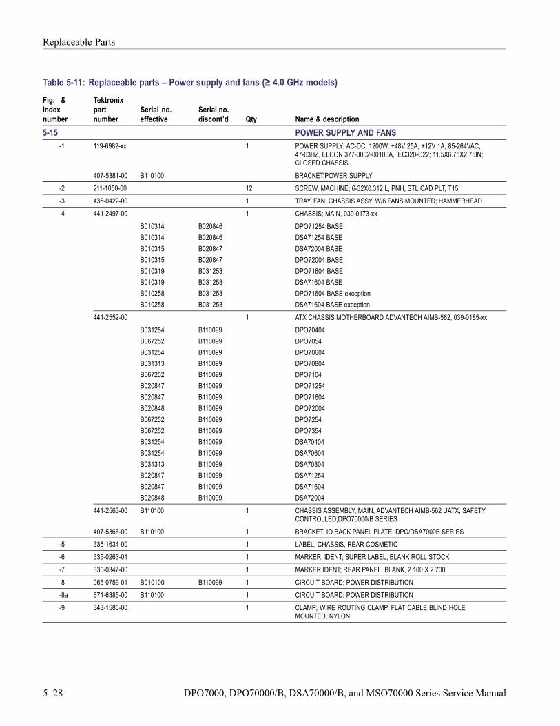
Replaceable Parts
Table 5-11: Replaceable parts – Power supply and fans (≥ 4.0 GHz models)Fig. &indexnumber
Tektronixpartnumber
Serial no.effective
Serial no.discont’d Qty Name & description
5-15 POWER SUPPLY AND FANS119-6982-xx 1 POWER SUPPLY: AC-DC; 1200W, +48V 25A, +12V 1A, 85-264VAC,
47-63HZ, ELCON 377-0002-00100A, IEC320-C22; 11.5X6.75X2.75IN;CLOSED CHASSIS
-1
407-5381-00 B110100 BRACKET;POWER SUPPLY-2 211-1050-00 12 SCREW, MACHINE; 6-32X0.312 L, PNH, STL CAD PLT, T15-3 436-0422-00 1 TRAY, FAN; CHASSIS ASSY, W/6 FANS MOUNTED; HAMMERHEAD
441-2497-00 1 CHASSIS; MAIN, 039-0173-xxB010314B010314B010315B010315B010319B010319B010258B010258
B020846B020846B020847B020847B031253B031253B031253B031253
DPO71254 BASEDSA71254 BASEDSA72004 BASEDPO72004 BASEDPO71604 BASEDSA71604 BASEDPO71604 BASE exceptionDSA71604 BASE exception
441-2552-00 1 ATX CHASSIS MOTHERBOARD ADVANTECH AIMB-562, 039-0185-xxB031254B067252B031254B031313B067252B020847B020847B020848B067252B067252B031254B031254B031313B020847B020847B020848
B110099B110099B110099B110099B110099B110099B110099B110099B110099B110099B110099B110099B110099B110099B110099B110099
DPO70404DPO7054DPO70604DPO70804DPO7104DPO71254DPO71604DPO72004DPO7254DPO7354DSA70404DSA70604DSA70804DSA71254DSA71604DSA72004
441-2563-00 B110100 1 CHASSIS ASSEMBLY, MAIN, ADVANTECH AIMB-562 UATX, SAFETYCONTROLLED;DPO70000/B SERIES
-4
407-5366-00 B110100 1 BRACKET, IO BACK PANEL PLATE, DPO/DSA7000B SERIES-5 335-1634-00 1 LABEL, CHASSIS, REAR COSMETIC-6 335-0263-01 1 MARKER, IDENT; SUPER LABEL, BLANK ROLL STOCK-7 335-0347-00 1 MARKER,IDENT; REAR PANEL, BLANK, 2.100 X 2.700-8 065-0759-01 B010100 B110099 1 CIRCUIT BOARD; POWER DISTRIBUTION
-8a 671-6385-00 B110100 1 CIRCUIT BOARD; POWER DISTRIBUTION-9 343-1585-00 1 CLAMP; WIRE ROUTING CLAMP, FLAT CABLE BLIND HOLE
MOUNTED, NYLON
5–28 DPO7000, DPO70000/B, DSA70000/B, and MSO70000 Series Service Manual

Replaceable Parts
Fig. &indexnumber
Tektronixpartnumber
Serial no.effective
Serial no.discont’d Qty Name & description
335-1603-00 1 LABEL, REAR, LEXAN, 039-0173-xx
335-2012-00 1 LABEL, REAR, LEXAN, 039-0185-xxB031254B067252B031254B031313B067252B020847B020847B020848B067252B067252B031254B031254B031313B020847B020847B020848
B110099B110099B110099B110099B110099B110099B110099B110099B110099B110099B110099B110099B110099B110099B110099B110099
DPO70404DPO7054DPO70604DPO70804DPO7104DPO71254DPO71604DPO72004DPO7254DPO7354DSA70404DSA70604DSA70804DSA71254DSA71604DSA72004
-10
335-2119-00 B110100 1 LABEL, REAR I/O PLATE, SAFETY CONTROLLED
DPO7000, DPO70000/B, DSA70000/B, and MSO70000 Series Service Manual 5–29

Replaceable Parts
Figure 5-15: Power supply and fans (≥ 4.0 GHz models)
5–30 DPO7000, DPO70000/B, DSA70000/B, and MSO70000 Series Service Manual

Replaceable Parts
Table 5-12: Replaceable parts – μATX assembly (≥ 4.0 GHz models)
Fig. & indexnumber
Tektronixpartnumber
Serial no.effective
Serialno.discont’d Qty Name & description
5-16 and 5-17 MOTHERBOARD-1 174-4797-00 1 CA ASSY; 20 PIN ATX POWER, SAFETY CONTROLLED
065-0745-02 1 SERVICE KIT FOR CPU BRD, CPU, FAN AND HEAT SINKASSEMBLY
167-0657-00 1 PROCESSOR; PENTIUM 4, 3.4 GHZ INTERNAL CLOCK, 400MHZBUS, W/O FAN HEATSINK, HH80552PG0962M
-2
119-7333-00 1 FAN, HEATSINK AND BRACKET
-3 211-0935-00 8 SCREW, MACHINE; 6-32 X 0.50, PNH, T-15, SST, PASSIVATED-4 174-4798-00 1 CA ASSY; 4 PIN P4 POWER-5 050-3723-00 1 PARTS REPLACEMENT KIT; AIMB562VG-00A1E, BIOS
562X12AN.BIN, ALC888 AUDIO CODEC, 039018601 WITH063425400 AIMB-562 AUDIO DRIVER, ADVANTECH VERSION5.10.0.5324; DPO7000, DPO/DSA70000, DPO/DSA7000B, VM6000,DSA8200, TLA5000B SERIES
-6 167-1048-00 2 IC, MEMORY; 128M X 64, 1GB DDR2 1.8V, 3-3-3;MT16HTF12864AY-40E, DIMM240,DS1
-7 119-7333-00 1 HEATSINK AND BRACKET
-8 342-1198-00 1 DAMPENER, PORON FOAM FOR P4 HEATSINK-9 174-5271-00 1 IDE CABLE WITH STRAIN RELIEF & PULL-TAB
DPO7000, DPO70000/B, DSA70000/B, and MSO70000 Series Service Manual 5–31

Replaceable Parts
Figure 5-16: 039-0173-xx and 065-0745-xx μATX assembly (≥ 4.0 GHz models)
5–32 DPO7000, DPO70000/B, DSA70000/B, and MSO70000 Series Service Manual

Replaceable Parts
Figure 5-17: 039-0185-xx μATX assembly (≥ 4.0 GHz models)
DPO7000, DPO70000/B, DSA70000/B, and MSO70000 Series Service Manual 5–33

Replaceable Parts
Table 5-13: Replaceable parts – Acquisition assembly (≥ 4.0 GHz models)Fig. &indexnumber
Tektronixpartnumber
Serial no.effective
Serial no.discont’d Qty Name & description
5-18 ACQUISITION-1 214-3903-00 8 SCREW, JACK; 4-40 X 0.312 LONG, 0.188 H HEX HEAD STAND OFF,
4-40 INT THD, X 0.312 THD EXT 4-40-2 - - - - - - - 1 ACQUISITION MODULE, RETURN TO TEKTRONIX FOR SERVICE-3 211-0752-00 10 SCREW,MACHINE; 6-32 X 0.75, PNH, TORX
-4 211-1050-00 7 SCREW, MACHINE; 6-32 X 0.312 L, PNH, STL CAD PLT, T15
Figure 5-18: Acquisition assembly (≥ 4.0 GHz models)
5–34 DPO7000, DPO70000/B, DSA70000/B, and MSO70000 Series Service Manual

Replaceable Parts
Table 5-14: Replaceable parts – Interface board (≥ 4.0 GHz models)
Fig. & indexnumber
Tektronixpartnumber
Serial no.effective
Serial no.discont’d Qty Name & description
5-19 and 5-20 INTERFACE BOARD065-0758-00 B010100 B110099 1 CIRCUIT BD ASSY; PCI BACKBONE BOARD
065-0825-00 B110100 1 KIT, SERVICE REPLACEMENT, BACKBONE BOARD ASSY,6646431XX TESTED W/ PACKAGING
**ATTACHED PARTS**386-7536-00 1 BRACKET, STIFFENER FOR PCI PCB
211-0747-00 5 SCREW, MACHINE; 6-32 X 0.188, PNH, STEEL, ZINC FINISH, T-15TORX DR
-1
**END ATTACHED PARTS**-2 211-1050-00 6 SCREW, MACHINE; 6-32 X 0.312 L, PNH, STL CAD PLT, T15-3 335-1604-00 1 LABEL REAR I/O PLATE, SAFETY CONTROLLED
-4 214-3903-00 2 SCREW, JACK; 4-40 X 0.312 LONG, 0.188 H HEX HEAD STANDOFF, 4-40 INT THD, X 0.312 THD EXT 4-40
-5 211-1206-00 2 SCREW, JACK; 2-56 ID X 4-40 OD, 0.188 HEX, SS
-6 214-1061-00 2 CONTACT, ELEC; GROUNDING, CU BE SAFETY CONTROLLED-7 386-7447-00 1 PLATE; REAR, PCI I/O
-8 174-5164-00 1 CA ASSY; USB 2.0
-9 679-6107-00 1 CIRCUIT BD ASSY; USB-10 211-1221-00 2 SCREW; M2.0 6-MM LONG PHILLIPS FLATHEAD ZINC-PLATED
-11 174-5048-00 1 CA ASSY; USB 1.0
-12 174-4241-00 1 CABLE ASSY; RIBBON, BUS, IDC, 32 AWG,16.50 L,60POS, BOX,IDC, FEMALE, RTANG, 0.050CTR X 2
-13 386-7481-00 1 BRACKET, BRACE BETWEEN PCI PCB AND DRIVE BRACKET
DPO7000, DPO70000/B, DSA70000/B, and MSO70000 Series Service Manual 5–35

Replaceable Parts
Figure 5-19: Interface board (≥ 4.0 GHz models) (B039999 and below)
5–36 DPO7000, DPO70000/B, DSA70000/B, and MSO70000 Series Service Manual

Replaceable Parts
Figure 5-20: Interface board (≥ 4.0 GHz models) (B040000 and above)
DPO7000, DPO70000/B, DSA70000/B, and MSO70000 Series Service Manual 5–37

Replaceable Parts
Table 5-15: Replaceable parts – Drives (≥ 4.0 GHz models)
Fig. & indexnumber
Tektronixpartnumber
Serial no.effective
Serialno.discont’d Qty Name & description
5-21 and 5-22 DRIVES065-0755-00 B010100 B110099 1 DISK DRIVE ASSY KIT, UNPROGRAMMED 119718900-1
065-0826-00 B110100 DISK DRIVE ASSY;SERVICE REPLACEMENT, UNPROGRAMMEDHARD DRIVE 1197524XX W/ PACKAGING;DSA/DPO70000B
-2 211-1050-00 8 SCREW, MACHINE; 6-32 X 0.312 L, PNH, STL CAD PLT, T15
-3 407-5069-00 1 BRACKET, RHDD; SATA COMBO CABLE, 3.5 INCH REMOVABLEHARD DISK DRIVE RECEPTACLE
-4 174-5169-00 1 CABLE ASSY; SATA COMBO, HARD DRIVE CABLE-5 174-5017-00 1 CABLE ASSEMBLY; DVD POWER-6 679-5915-00 1 CKT BD SUBASSY; DVD-CD/RW ADAPTER, UNTESTED,
389-3689-00 WIRED-7 129-1618-00 1 SPACER; DVD-CD/RW SLIMLINE DRIVE ADAPTER, PLASTIC
-8 211-0950-00 4 SCREW, MACHINE; M2X.4X3L, PHL, PNH, STL NI PL-9 407-5156-00 1 BRACKET, DVD-CD/RW; ADAPTER FOR DVD-CD/RW SLIMLINE-10 119-7196-00 1 DISK DRIVE; OPTICAL, 644MB, CD-RW/DVD ROM, COMBO,
16.7 MB/SEC, IDE/ATAPI; DW-224E-C93-11 441-2496-01 1 CHASSIS; DRIVE BAY; METAL
5–38 DPO7000, DPO70000/B, DSA70000/B, and MSO70000 Series Service Manual

Replaceable Parts
Figure 5-21: Drives (≥ 4.0 GHz models) (B039999 and below)
DPO7000, DPO70000/B, DSA70000/B, and MSO70000 Series Service Manual 5–39

Replaceable Parts
Figure 5-22: Drives (≥ 4.0 GHz models) (B040000 and above)
5–40 DPO7000, DPO70000/B, DSA70000/B, and MSO70000 Series Service Manual

Replaceable Parts
Table 5-16: Replaceable parts – Standard accessories (≥ 4.0 GHz models)Fig. &indexnumber
Tektronixpartnumber
Serial no.effective
Serial no.discont’d Qty Name & description
STANDARD ACCESSORIESCABLE ASSY, POWERSee
Description1
OptionA0A1A2A3A5A6A10A11
CountryN. AMERICAUNIV EUROUKAUSTRALIASWITZERLANDJAPANCHINAINDIA
P/N161-0213-00161-0209-06161-0210-07161-0211-05161-0212-00161-0213-00161-0320-XX161-0325-00
QUICKSTART USER MANUALSeeDescription
1
OptionL0L1L3L5L7L8L9L10
LanguageENGLISHFRENCHGERMANJAPANESECHINESE, SCHINESE, TKOREANRUSSIAN
P/N071-2597-XX071-2598-XX071-2599-XX071-2600-XX071-2602-XX071-2603-XX071-2601-XX071-2604-XX
020-2693-19 1 PRODUCT SW CD AND INSTRUCTIONS119-7054-00 1 POINTER ASSY; MOUSE, MICROSOFT BLACK OPTICAL WHEELED,
USB AND PS2119-7083-00 1 KEYBOARD; USB W/ 2-PORT HUB; MINI (69 KEYS) BLACK
071-1733-01 1 MANUAL, TECH; QUICK START, ENGLISH020-2700-00 1 CD; OPTIONAL APPS
TCA-292MM 4 ADAPTER; TEKCONNECT, 2.92MM
TCA-BNC 4 ADAPTER; TEKCONNECT, BNC200-4963-00 1 COVER; FRONT063-3781-00 1 CD; NERO, DVD WRITER SW
DPO7000, DPO70000/B, DSA70000/B, and MSO70000 Series Service Manual 5–41

Replaceable Parts
Table 5-17: Replaceable parts – External 1 (MSO models)Fig. &indexnumber
Tektronixpartnumber
Serial no.effective
Serial no.discont’d Qty Name & description
5-23- EXTERNAL PARTS-1 016-1441-01 1 ACCESSORY POUCH; BLACK CORDURA-2 200-5119-00 1 COVER, TOP; COSMETIC
-3 211-0967-00 2 SCREW; 6-32X 0.25,PNH,T-15, W/FLAT WASHER, STEEL, ZINC FINISH-4 355-0298-00 1 STUD.SNAP; 0.570 DIA, 0.165 THK, STAINLESS STEEL-5 200-5060-00 1 COVER; EMI TOP
-6 211-1050-00 19 SCREW, MACHINE; 6-32 X 0.312 L, PNH, STL CAD PLT, T15-7 348-1859-00 4 FOOT; REAR, W/ CORD WRAP, THERMOPLASTIC-7a 211-0721-00 4 SCREW, MACHINE; 6-32 X 0.375, PNH, STEEL, ZINC FINISH WITH
NYLOC PATCH, T-15-8 101-0173-01 1 TRIM, ACQUISITION INSERT
-9 101-0171-00 1 TRIM RING; FR110, PC/ABS-10 200-4963-00 1 COVER, FRONT; PC/ABS ALLOY BAYBLEND-11 101-0174-00 1 TRIM, DVD
335-2169-00 1 LABEL, NOMENCLATURE, MSO70404335-2170-00 1 LABEL, NOMENCLATURE, MSO70604
335-2171-00 1 LABEL, NOMENCLATURE, MSO70804335-2172-00 1 LABEL, NOMENCLATURE, MSO71254335-2173-00 1 LABEL, NOMENCLATURE, MSO71604
-12
335-2174-00 1 LABEL, NOMENCLATURE, MSO72004-13 211-0721-00 4 SCREW, MACHINE; 6-32 X 0.375, PNH, STEEL, ZINC FINISH WITH
NYLOC PATCH, T-15 TORX DR
5–42 DPO7000, DPO70000/B, DSA70000/B, and MSO70000 Series Service Manual

Replaceable Parts
Figure 5-23: External 1 (MSO models)
DPO7000, DPO70000/B, DSA70000/B, and MSO70000 Series Service Manual 5–43

Replaceable Parts
Table 5-18: Replaceable parts – External 2 (MSO models)Fig. &indexnumber
Tektronixpartnumber
Serial no.effective
Serial no.discont’d Qty Name & description
5-24- EXTERNAL PARTS-1 174-5226-00 1 CABLE ASSY; LINE FILTER-2 211-1050-00 16 SCREW, MACHINE; 6-32 X 0.312 L, PNH, STL CAD PLT, T15
200-5123-00 1 COVER; EMI BOTTOM, MSO70804/70604/70404-3
200-5124-00 1 COVER; EMI BOTTOM, MSO72004/71604/71254-4 200-5125-00 1 COVER, BOTTOM; COSMETIC; W/FEET-5 212-0232-00 2 SCREW,MACHINE; 8-32 X 1.125L, PNH, STL, BLACK ZINC SPEC
#ASTM B633 TYPE II, T-20
367-0528-00 1 HANDLE, CARRYING; DUAL DUROMETER MOLDED,POLYPROPYLENE, VINYL GRIP SECTION
-6
407-4887-00 1 BRACKET; HANDLE BASE, PC/ABS ALLOY, BAYER BAYBLEND FR-110,TEK BLUE
-7 348-1951-00 1 FRONT FOOT ASSEMBLY, FLIP (2), SAFETY CONTROLLED-8 211-1224-00 2 SCREW, MACHINE, BLACK
5–44 DPO7000, DPO70000/B, DSA70000/B, and MSO70000 Series Service Manual

Replaceable Parts
Figure 5-24: External parts 2 (MSO models)
DPO7000, DPO70000/B, DSA70000/B, and MSO70000 Series Service Manual 5–45

Replaceable Parts
Table 5-19: Replaceable parts – Front panel and display (MSO models)Fig. & indexnumber
Tektronixpart number
Serial no.effective
Serial no.discont’d Qty Name & description
5-25- FRONT PANEL AND DISPLAY-1 174-5165-00 1 CABLE ASSY; POWER SWITCH
-2 065-0756-02 1 MODULE ASSY;SERVICE REPLACEMENT KIT,614104101 FRONT PANELASSEMBLY W/ PACKAGING;DPO7000,DPO/DSA70000 SERIES
-3 366-0859-01 1 ASSEMBLY, KNOB; .470 DIAMETER, SOFT TOUCH-4 366-0860-01 1 ASSEMBLY, KNOB; .685 DIAMETER, SOFT TOUCH-5 366-0861-01 1 ASSEMBLY, KNOB; .925 DIAMETER, SOFT TOUCH
-6 174-5162-00 1 CABLE ASSY; DISPLAY ADAPTER TO FRONT PANEL BOARD-7 065-0827-01 1 COMPONENT KIT; LCD DISPLAY ADAPTER MODULE SUBASSEMBLY,
STANDARD-8 065-0819-00 1 MODULE ASSY;SERVICE REPLACEMENT KIT,POWER BUTTON ASSY
W/ PACKAGING, FOR ADVANTECH AIMB-562 MOTHERBOARD-9 211-1050-00 2 SCREW, MACHINE; 6-32 X 0.312 L, PNH, STEEL, ZINC FINISH, T15
5–46 DPO7000, DPO70000/B, DSA70000/B, and MSO70000 Series Service Manual

Replaceable Parts
Figure 5-25: Front panel and display (MSO models)
DPO7000, DPO70000/B, DSA70000/B, and MSO70000 Series Service Manual 5–47

Replaceable Parts
Table 5-20: Replaceable parts – Drive bay 1 (MSO models)
Fig. & indexnumber
Tektronixpartnumber
Serial no.effective
Serialno.discont’d Qty Name & description
5-26- DRIVE BAY 1-1 441-2602-00 1 CHASSIS, DRIVE BAYS (DVD AND HD)-2 211-1050-00 11 SCREW, MACHINE; 6-32 X 0.312 L, PNH, STL CAD PLT, T15
5–48 DPO7000, DPO70000/B, DSA70000/B, and MSO70000 Series Service Manual

Replaceable Parts
Figure 5-26: Drive bay 1 (MSO models)
DPO7000, DPO70000/B, DSA70000/B, and MSO70000 Series Service Manual 5–49

Replaceable Parts
Table 5-21: Replaceable parts – Drive bay 2 (MSO models)
Fig. & indexnumber
Tektronixpartnumber
Serial no.effective
Serialno.discont’d Qty Name & description
5-27- DRIVE BAY 2-1 065-0844-00 1 DRIVE ASSEMBLY,WITH PACKAGING;6505284XX,PRGM HDD ASSY
WITH OS/APPS SW ON HIDDEN PARTITION, FOR ADVANTECHAIMB-566 MOTHERBOARD;MSO70000
-2 211-0722-00 8 SCREW, MACHINE; 6-32 X 0.312 L, PNH, STL CAD PLT, T15
-3 174-5169-00 1 CABLE ASSY; SATA COMBO, HARD DRIVE CABLE-4 174-5650-00 1 CABLE ASSY; SATA-DVD, DATA, AND POWER-5 211-0950-00 4 SCREW, MACHINE; M2X.4X3L, PHL, PNH, STL NI PL
-6 407-5156-00 1 BRACKET, DVD-CD/RW; ADAPTER FOR DVD-CD/RW SLIMLINE-7 065-0807-00 1 DISK DRIVE; OPTICAL, 644MB, CD-RW/DVD ROM, COMBO,
16.7 MB/SEC, IDE/ATAPI; DW-224E-C93
5–50 DPO7000, DPO70000/B, DSA70000/B, and MSO70000 Series Service Manual

Replaceable Parts
Figure 5-27: Drive bay 2 (MSO models)
DPO7000, DPO70000/B, DSA70000/B, and MSO70000 Series Service Manual 5–51

Replaceable Parts
Table 5-22: Replaceable parts – Interface board (MSO models)
Fig. & indexnumber
Tektronixpartnumber
Serial no.effective
Serial no.discont’d Qty Name & description
5-28- INTERFACE BOARD065-0828-00 1 CIRCUIT BD ASSY; PCIe BACKBONE BOARD, TESTED
**ATTACHED PARTS**386-7536-00 1 BRACKET, STIFFENER FOR PCIe PCB
211-0747-00 5 SCREW, MACHINE; 6-32 X 0.188, PNH, STEEL, ZINC FINISH, T-15TORX DR
-1
**END ATTACHED PARTS**-2 211-1050-00 7 SCREW, MACHINE; 6-32 X 0.312 L, PNH, STL CAD PLT, T15-3 335-2152-00 1 LABEL, I/O FOR PCIe PCB (ATTACHES TO PCIe PCB REAR
BRACKET)-4 211-1206-00 2 SCREW, JACK; 2-56 ID X 4-40 OD, 0.188 HEX, SS-5 213-1061-00 2 JACKSCREW; 6-32 EXT THD, M3.5 X 0.6-6 INT THD, 410 SS,
PASSIVATE
-6 386-7537-00 1 BRACKET, PCIE PCB MOUNT AND MS WINDOWS LABEL HOLDER,SAFETY CONTROLLED
-7 174-5164-00 1 CA ASSY; USB 2.0
-8 679-6107-00 1 CIRCUIT BD ASSY; USB-9 211-1221-00 2 SCREW; M2.0 6-MM LONG PHILLIPS FLATHEAD ZINC-PLATED
-10 174-5048-00 1 CA ASSY; USB 1.0
-11 174-4241-00 1 CABLE ASSY; RIBBON, BUS, IDC, 32 AWG,16.50 L,60POS, BOX,IDC, FEMALE, RTANG, 0.050CTR X 2
5–52 DPO7000, DPO70000/B, DSA70000/B, and MSO70000 Series Service Manual

Replaceable Parts
Figure 5-28: Interface board (MSO models)
DPO7000, DPO70000/B, DSA70000/B, and MSO70000 Series Service Manual 5–53

Replaceable Parts
Table 5-23: Replaceable parts – Power supply and fans (MSO models)Fig. &indexnumber
Tektronixpartnumber
Serial no.effective
Serialno.discont’d Qty Name & description
5-29- POWER SUPPLY AND FANS119-6982-xx 1 POWER SUPPLY: AC-DC; 1200W, +48V 25A, +12V 1A, 85-264VAC,
47-63HZ, ELCON 377-0002-00100A, IEC320-C22; 11.5X6.75X2.75IN;CLOSED CHASSIS
**ATTACHED PARTS**407-5381-00 BRACKET;POWER SUPPLY
-1
**END ATTACHED PARTS**-2 211-0721-00 12 SCREW, MACHINE; 6-32 X 0.375, PNH, STEEL, ZINC FINISH WITH
NYLOC PATCH, T-15 TORX DR
-3 436-0422-00 1 TRAY, FAN; CHASSIS ASSY, W/6 FANS MOUNTED; HAMMERHEAD-4 335-2167-00 1 LABEL, CHASSIS, REAR COSMETIC-5 335-0263-01 1 MARKER, IDENT; SUPER LABEL, BLANK ROLL STOCK
-6 335-0347-00 1 MARKER,IDENT; REAR PANEL, BLANK, 2.100 X 2.700-7 870-0210-00 1 CIRCUIT BOARD ASSY;POWER DISTRIBUTION, 8780210XX TESTED
W/ PACKAGING-8 335-2153-00 1 LABEL, M-BOARD IO, AIMB566
-9 343-1719-00 1 CLIP, PCB RETENTION BRACKET (PWR-DIST TO PCI), SAFETYCONTROLLED
-10 211-1050-00 15 SCREW, MACHINE; 6-32 X 0.312 L, PNH, STEEL, ZINC FINISH, T15
5–54 DPO7000, DPO70000/B, DSA70000/B, and MSO70000 Series Service Manual
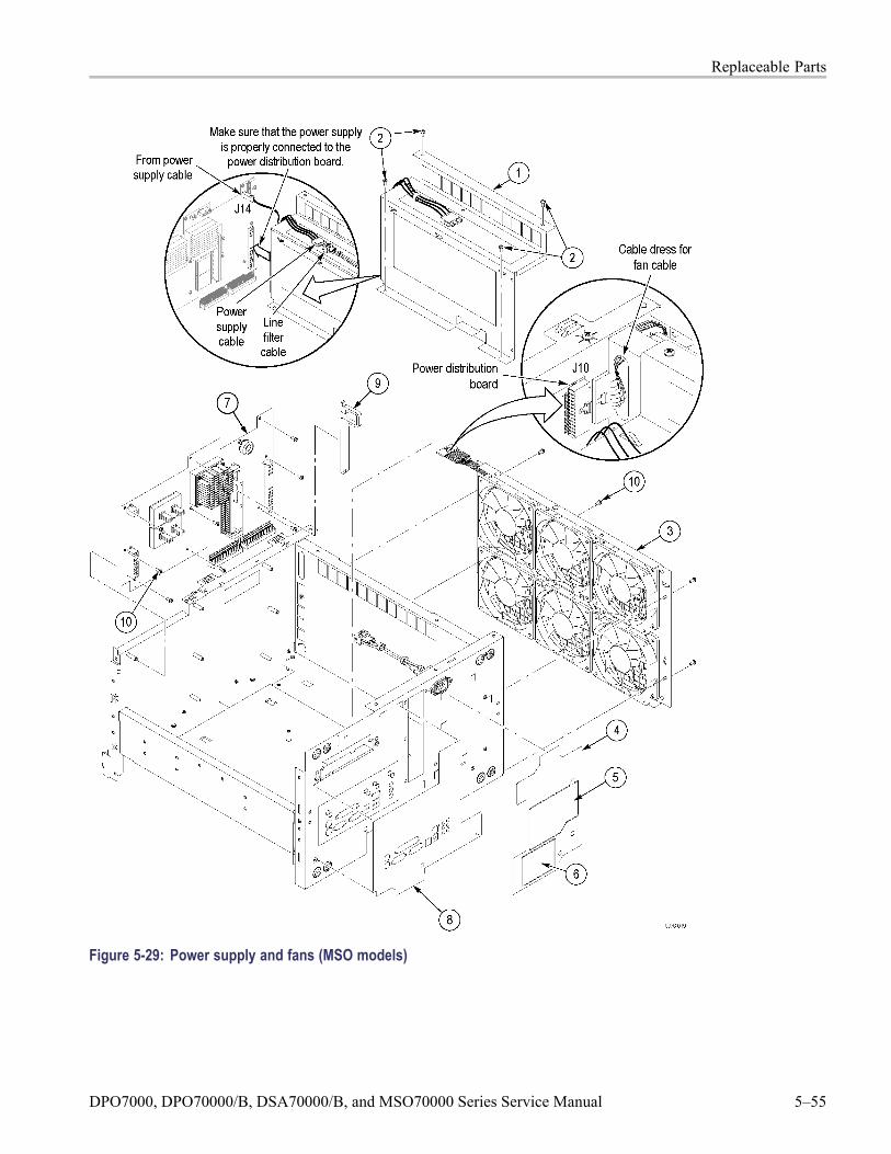
Replaceable Parts
Figure 5-29: Power supply and fans (MSO models)
DPO7000, DPO70000/B, DSA70000/B, and MSO70000 Series Service Manual 5–55

Replaceable Parts
Table 5-24: Replaceable parts – Acquisition assembly (MSO models)Fig. &indexnumber
Tektronixpartnumber
Serial no.effective
Serial no.discont’d Qty Name & description
5-30- ACQUISITION-1 214-3903-00 8 SCREW, JACK; 4-40 X 0.312 LONG, 0.188 H HEX HEAD STAND OFF,
4-40 INT THD, X 0.312 THD EXT 4-40-2 - - - - - - - 1 ACQUISITION MODULE, RETURN TO TEKTRONIX FOR SERVICE-3 211-0752-00 10 SCREW,MACHINE; 6-32 X 0.75, PNH, TORX
-4 211-1050-00 7 SCREW, MACHINE; 6-32 X 0.312 L, PNH, STL CAD PLT, T15
5–56 DPO7000, DPO70000/B, DSA70000/B, and MSO70000 Series Service Manual

Replaceable Parts
Figure 5-30: Acquisition assembly (MSO models)
DPO7000, DPO70000/B, DSA70000/B, and MSO70000 Series Service Manual 5–57

Replaceable Parts
Table 5-25: Replaceable parts – MSO module (MSO models)Fig. &indexnumber
Tektronixpartnumber
Serial no.effective
Serial no.discont’d Qty Name & description
5-31- MSO Module-1 407-5448-00 1 BRACKET, FAN, PWR DIST PCB-2 119-7036-00 1 FAN ASSEMBLY; DC,12V;0.105A,8.6 CFM,30DBA,3 LEAD, TACH
OUTPUT, WITH CONN & HOUSING,SAFETY CONTROLLED-2 211-1050-00 7 SCREW, MACHINE; 6-32 X 0.312 L, PNH, STL CAD PLT, T15
-3 174-5517-00 1 CABLE ASSY;PCIe, STRAIGHT CONNECTOR ON BOTH ENDS,SAFETY CONTROLLED
-4 - - - - - - - 1 MSO MODULE, RETURN TO TEKTRONIX FOR SERVICE-5 174-5516-00 1 CABLE, POWER, 2X4 WITH MINIFIT JR CONNS, SAFETY
CONTROLLED
5–58 DPO7000, DPO70000/B, DSA70000/B, and MSO70000 Series Service Manual

Replaceable Parts
Figure 5-31: MSO module (MSO models)
DPO7000, DPO70000/B, DSA70000/B, and MSO70000 Series Service Manual 5–59

Replaceable Parts
Table 5-26: Replaceable parts – μATX 1 (MSO models)Fig. &indexnumber
Tektronixpartnumber
Serial no.effective
Serial no.discont’d Qty Name & description
μATX 1-1 174-5629-00 1 CABLE, LVDS VIDEO WITH 2X20 HIROSE CONNECTORS;PCIe J18
to μATX LVDS1
-2 174-5763-00 1 CABLE, SATA TO E-SATA, DATA ONLY; RP e-SATA to μATX SATA 2-3 441-2585-00 1 BRACKET, IO M-BOARD, AMB566, SAFETY CONTROLLED
**ATTACHING PARTS**211-1050-00 10 SCREW, MACHINE; 6-32 X 0.312 L, PNH, STEEL, ZINC FINISH, T15214-3903-01 6 SCREW, JACK; 4-40 X 0.312 EXT THD, 4-40 INT THD, 0.188 HEX, ZINC
PLATED STEEL
**END ATTACHING PARTS**
5–60 DPO7000, DPO70000/B, DSA70000/B, and MSO70000 Series Service Manual

Replaceable Parts
Figure 5-32: μATX 1 (MSO models)
DPO7000, DPO70000/B, DSA70000/B, and MSO70000 Series Service Manual 5–61

Replaceable Parts
Table 5-27: Replaceable parts – μATX 2 (MSO models)Fig. &indexnumber
Tektronixpartnumber
Serial no.effective
Serial no.discont’d Qty Name & description
5-33- μATX 2-1 174-4797-00 1 CA ASSY; 20 PIN ATX POWER,SAFETY CONTROLLED; PWR DIST J8
to μATX EATXPWR1
-2 119-7333-00 1 P4 LGA775 FAN-SINK-BRACKET FROM AVC. SAFETY CONTROLLED-3 211-1050-00 8 SCREW, MACHINE; 6-32 X 0.312 L, PNH, STEEL, ZINC FINISH, T15-4 174-4798-00 1 CA ASSY; 4 PIN P4 POWER,SAFETY CONTROLLED;PWR DIST J9
to μATX 12V-5 167-1348-00 1 PROCESSOR; INTEL CORE 2 DUO, 3.0 GHZ, WOLFDALE, E8400;
65W; BUS SPD 1333MHZ; FC-LGA775 PKG, W/O FAN and HEATSINKEU80570PJ0806M SLB9J
-6 039-0188-00 1 COMPUTER BOARD;ADVANTECH, MICROATX, LGA 775 CORE 2DUO, DDR2, PCI-E X4, DUAL CH LVDS, DVI-I, SINGLE GBE LAN;ADVANTECH AIMB-566, SAFETY CONTROLLED
-7 - - - - - - - 1 HEAT SINK BRACKETPART OF ITEM 2 IN THIS LIST
-8 342-1198-00 1 DAMPENER FOR SHOCK AND VIBRATION, HEMISPHERE GEOMETRY,1.00 IN DIA SPHERE (.500 IN HEIGHT), SORBOTHANE PN 0510115,BLACK, 30 DUROMETER
-9 167-1493-00 2 IC, MEMORY;256MBIT X 64, 2GB DDR2 1.8V, 6-6-6, 800 MT/S;MT16HTF25664AY-800, DIMM240, PC6400
5–62 DPO7000, DPO70000/B, DSA70000/B, and MSO70000 Series Service Manual

Replaceable Parts
Figure 5-33: μATX 2 (MSO models)
DPO7000, DPO70000/B, DSA70000/B, and MSO70000 Series Service Manual 5–63

Replaceable Parts
Table 5-28: Standard accessories (MSO models)Fig. &indexnumber
Tektronixpartnumber
Serial no.effective
Serial no.discont’d Qty Name & description
STANDARD ACCESSORIESCABLE ASSY, POWERSee
Description1
OptionA0A1A2A3A5A6A10A11
CountryN. AMERICAUNIV EUROUKAUSTRALIASWITZERLANDJAPANCHINAINDIA
P/N161-0213-00161-0209-00161-0210-00161-0211-01161-0212-00161-0213-00161-0320-00161-0325-00
QUICKSTART USER MANUALSeeDescription
1
OptionL0L1L3L5L7L8L9L10
LanguageENGLISHFRENCHGERMANJAPANESECHINESE, SCHINESE, TKOREANRUSSIAN
P/N071-2617-XX071-2618-XX071-2619-XX071-2620-XX071-2622-XX071-2623-XX071-2621-XX071-2624-XX
016-1441-XX 1 ACCESSORY POUCH; BLACK CORDURA020-3026-XX 1 Product Software DVD, MSO70000 Series
020-3019-XX 1 Operating System Restore DVD, MSO70000 Series020-2700-XX 1 CD; OPTIONAL APPS119-7054-00 1 POINTER ASSY; MOUSE, MICROSOFT BLACK OPTICAL WHEELED,
USB AND PS2119-7083-00 1 KEYBOARD; USB W/ 2-PORT HUB; MINI (69 KEYS) BLACK
TCA-292MM 4 ADAPTER; TEKCONNECT, 2.92MM
TCA-BNC 1 ADAPTER; TEKCONNECT, BNC200-4963-01 1 COVER; FRONT
063-3781-01 1 CD; NERO, DVD WRITER SW006-3415-05 1 STRAP,WRIST; 3M TYPE 2214, ADJUSTABLE,6 FT COILED CORD
5–64 DPO7000, DPO70000/B, DSA70000/B, and MSO70000 Series Service Manual