Downloaded from
228
2001 - 2005 MOTORCYCLE SERVICE MANUAL Model : YJ50RAP, YJ50RAR, YJ50RAS, YJ50RAT, YJ50RN, YJ50RP, YJ50RR, YJ50RS, YJ50RT 5PP281972000 *5PP281972000* Downloaded from www.ScooterTime.net
-
Upload
khangminh22 -
Category
Documents
-
view
0 -
download
0
Transcript of Downloaded from

2001 - 2005MOTORCYCLE
SERVICE MANUAL
Model : YJ50RAP, YJ50RAR, YJ50RAS,YJ50RAT, YJ50RN, YJ50RP, YJ50RR,
YJ50RS, YJ50RT
5PP281972000 *5PP281972000*
Downlo
aded
from w
ww.Sco
oterT
ime.n
et
murad

Downlo
aded
from w
ww.Sco
oterT
ime.n
et

EAS00000
YJ50RNSERVICE MANUAL
©2000 by Yamaha Motor Co., Ltd. First edition, December, 2000
All rights reserved. Any reproduction or unauthorized use
without the written permission of Yamaha Motor Co., Ltd. is expressly prohibited.
Downlo
aded
from w
ww.Sco
oterT
ime.n
et

EAS00002
NOTICEThis manual was produced by the Yamaha Motor Company, Ltd. primarily for use by Yamaha deal-ers and their qualified mechanics. It is not possible to include all the knowledge of a mechanic inone manual. Therefore, anyone who uses this book to perform maintenance and repairs on Yamahavehicles should have a basic understanding of mechanics and the techniques to repair these typesof vehicles. Repair and maintenance work attempted by anyone without this knowledge is likely torender the vehicle unsafe and unfit for use.
Yamaha Motor Company, Ltd. is continually striving to improve all of its models. Modifications andsignificant changes in specifications or procedures will be forwarded to all authorized Yamaha deal-ers and will appear in future editions of this manual where applicable.
NOTE:@
Designs and specifications are subject to change without notice.
EAS00005
IMPORTANT MANUAL INFORMATIONParticularly important information is distinguished in this manual by the following.
The Safety Alert Symbol means ATTENTION! BECOME ALERT! YOURSAFETY IS INVOLVED!
Failure to follow WARNING instructions could result in severe injury or death tothe scooter operator, a bystander or a person checking or repairing the scooter.
A CAUTION indicates special precautions that must be taken to avoid damageto the scooter.
A NOTE provides key information to make procedures easier or clearer.
WARNING
CAUTION:
NOTE:
Downlo
aded
from w
ww.Sco
oterT
ime.n
et

EAS00007
HOW TO USE THIS MANUALThis manual is intended as a handy, easy-to-read reference book for the mechanic. Comprehensiveexplanations of all installation, removal, disassembly, assembly, repair and check procedures arelaid out with the individual steps in sequential order.1The manual is divided into chapters. An abbreviation and symbol in the upper right corner of each
page indicate the current chapter. Refer to “SYMBOLS”.
2Each chapter is divided into sections. The current section title is shown at the top of each page,except in Chapter 3 (“PERIODIC CHECKS AND ADJUSTMENTS”), where the sub-section title(s)appears.
3Sub-section titles appear in smaller print than the section title.
4To help identify parts and clarify procedure steps, there are exploded diagrams at the start ofeach removal and disassembly section.
5Numbers are given in the order of the jobs in the exploded diagram. A circled number indicates adisassembly step.
6Symbols indicate parts to be lubricated or replaced. Refer to “SYMBOLS”.
7A job instruction chart accompanies the exploded diagram, providing the order of jobs, names ofparts, notes in jobs, etc.
8 Jobs requiring more information (such as special tools and technical data) are described sequen-tially.
Downlo
aded
from w
ww.Sco
oterT
ime.n
et

EAS00009
SYMBOLSThe following symbols are not relevant toevery vehicle. Symbols 1 to 8 indicate the subject of eachchapter.
1 General information 2 Specifications 3 Periodic checks and adjustments 4 Chassis5 Engine 6 Carburetor(s) 7 Electrical system 8 Troubleshooting
Symbols 9 to F indicate the following.
9 Serviceable with engine mounted 0 Filling fluid A Lubricant B Special tool C Tightening torque D Wear limit, clearance E Engine speed F Electrical data
Symbols G to L in the exploded diagramsindicate the types of lubricants and lubricationpoints.G Engine oil H Gear oil I Molybdenum disulfide oil J Wheel bearing grease K Lithium soap base grease L Molybdenum disulfide grease
Symbols M to N in the exploded diagramsindicate the following.
M Apply locking agent (LOCTITE®) N Replace the part
1 2
3 4
5 6
7 8
9 0
A B
C D
E F
G H I
J K L
M N
GENINFO SPEC
CHKADJ CHAS
ENG CARB
– +ELEC TRBLSHTG
T R..
E G M
B LS M
LTNew
Downlo
aded
from w
ww.Sco
oterT
ime.n
et

EAS00011
TABLE OF CONTENTS
GENERAL INFORMATION GEN INFO 1
SPECIFICATIONSSPEC 2
PERIODIC CHECKS AND ADJUSTMENTS CHK
ADJ 3CHASSIS
CHAS 4ENGINE
ENG 5CARBURETION
CARB 6ELECTRICAL SYSTEM
ELEC 7TROUBLESHOOTING TRBL
SHTG 8
– +Downlo
aded
from w
ww.Sco
oterT
ime.n
et

Downlo
aded
from w
ww.Sco
oterT
ime.n
et

GENINFO
1Downlo
aded
from w
ww.Sco
oterT
ime.n
et

GENINFO
CHAPTER 1GENERAL INFORMATION
SCOOTER IDENTIFICATION..........................................................................1-1VEHICLE IDENTIFICATION NUMBER .....................................................1-1MODEL CODE ..........................................................................................1-1
IMPORTANT INFORMATION .........................................................................1-2PREPARATION FOR REMOVAL AND DISASSEMBLY...........................1-2REPLACEMENT PARTS...........................................................................1-2GASKETS, OIL SEALS AND O-RINGS ....................................................1-2LOCK WASHERS/PLATES AND COTTER PINS .....................................1-2BEARINGS AND OIL SEALS ....................................................................1-3CIRCLIPS ..................................................................................................1-3CHECKING THE CONNECTIONS............................................................1-4
SPECIAL TOOLS ............................................................................................1-5
Downlo
aded
from w
ww.Sco
oterT
ime.n
et

GENINFO
Downlo
aded
from w
ww.Sco
oterT
ime.n
et

1 - 1
GENINFO
EAS00015
GENERAL INFORMATION SCOOTER IDENTIFICATIONEAS00017
VEHICLE IDENTIFICATION NUMBERThe vehicle identification number 1 isstamped into the frame.
1
EAS00018
MODEL CODEThe model code label 1 is affixed to the loca-tion shown in the figure. Record the informa-tion on this label in the space provided. Thisinformation will be needed to order spareparts.
SCOOTER IDENTIFICATION
Downlo
aded
from w
ww.Sco
oterT
ime.n
et

1 - 2
GENINFOIMPORTANT INFORMATION
EAS00020
IMPORTANT INFORMATIONPREPARATION FOR REMOVAL AND DISASSEMBLY1. Before removal and disassembly, remove all
dirt, mud, dust and foreign material. 2. Use only the proper tools and cleaning
equipment. Refer to “SPECIAL TOOLS”.
3. When disassembling, always keep matedparts together. This includes gears, cylin-ders, pistons and other parts that have been“mated” through normal wear. Mated partsmust always be reused or replaced as anassembly.
4. During disassembly, clean all of the partsand place them in trays in the order of dis-assembly. This will speed up assembly andallow for the correct installation of all parts.
5. Keep all parts away from any source of fire.
EAS00021
REPLACEMENT PARTSUse only genuine Yamaha parts for allreplacements. Use oil and grease recom-mended by Yamaha for all lubrication jobs.Other brands may be similar in function andappearance, but inferior in quality.
EAS00022
GASKETS, OIL SEALS AND O-RINGS1. When overhauling the engine, replace all
gaskets, seals and O-rings. All gasket sur-faces, oil seal lips and O-rings must becleaned.
2. During reassembly, properly oil all matingparts and bearings and lubricate the oil seallips with grease.
EAS00023
LOCK WASHERS/PLATES AND COTTER PINSAfter removal, replace all lock washers/plates1 and cotter pins. After the bolt or nut hasbeen tightened to specification, bend the locktabs along a flat of the bolt or nut.
Downlo
aded
from w
ww.Sco
oterT
ime.n
et
1 - 3
GENINFOIMPORTANT INFORMATION
EAS00024
BEARINGS AND OIL SEALSInstall bearings and oil seals so that the manu-facturer’s marks or numbers are visible. Wheninstalling oil seals, lubricate the oil seal lipswith a light coat of lithium soap base grease.Oil bearings liberally when installing, if appro-priate.1 Oil seal
CAUTION:@
Do not spin the bearing with compressedair because this will damage the bearingsurfaces.
1 Bearing
EAS00025
CIRCLIPSBefore reassembly, check all circlips carefullyand replace damaged or distorted circlips.Always replace piston pin clips after one use.When installing a circlip 1, make sure thesharp-edged corner 2 is positioned oppositethe thrust 3 that the circlip receives.4 Shaft
Downlo
aded
from w
ww.Sco
oterT
ime.n
et

1 - 4
GENINFOIMPORTANT INFORMATION
EAS00026
CHECKING THE CONNECTIONSCheck the leads, couplers, and connectors forstains, rust, moisture, etc.1. Disconnect: • lead • coupler • connector
2. Check: • lead • coupler • connector
Moisture → Dry with an air blower. Rust/stains → Connect and disconnect sev-eral times.
3. Check:• all connections
Loose connection → Connect properly.
NOTE:@
If the pin 1 on the terminal is flattened, bend itup.
4. Connect: • lead • coupler • connector
NOTE:@
Make sure all connections are tight.
5. Check: • continuity
(with the pocket tester)
NOTE:@
• If there is no continuity, clean the terminals. • When checking the wire harness, perform
steps (1) to (3). • As a quick remedy, use a contact revitalizer
available at most part stores.
Pocket tester YU-03112
Downlo
aded
from w
ww.Sco
oterT
ime.n
et

1 - 5
GENINFO
EAS00027
SPECIAL TOOLSThe following special tools are necessary for complete and accurate tune-up and assembly. Useonly the appropriate special tools as this will help prevent damage caused by the use of inappropri-ate tools or improvised techniques. Special tools, part numbers or both may differ depending on thecountry.When placing an order, refer to the list provided below to avoid any mistakes.
Tool No. Tool name/Function Illustration
YM-01409
Oil seal guide
This tool is used to install oil seals.
YM-01411
Crankshaft installer spacer
This tool is used to install the crank-shaft.
YM-34487
Dynamic spark tester
This tool is used to check the ignition system components.
YS-28891
Clutch spring holder
This tool is used to disassembly and assembly the secondary pulley.
YU-01135
Crankcase separating tool
This tool is used to remove the crank-shaft and to separate the crankcase.
YU-01235
Rotor holding tool
This tool is used to hold the generator rotor when removing or installing the generator rotor bolt.
YU-01444
Steering nut wrench (45 mm)
This tool is used to loosen and tighten the lower steering stem nut.
SPECIAL TOOLS
Downlo
aded
from w
ww.Sco
oterT
ime.n
et

1 - 6
GENINFO
YU-01701
Sheave holder
This tool is used to hold the clutch hous-ing when removing or installing the clutch housing nut.
YU-03112
Pocket tester
This tool is used to check the electrical system.
YU-33223
Compression gauge
This tool is used to measure engine compression.
YU-33975
Steering nut wrench
This tool is used to loosen or tighten the steering stem ring nut.
YU-8036-A
Inductive tachometer
This tool is used to check engine speed.
Crankshaft installer tool set
YU-90050Crankshaft installer pot
YU-90058Crankshaft installer bolt
YU-90060
Crankshaft installer tool setCrankshaft installer potCrankshaft installer bolt
These tools are used to install the crankshaft.
YU-90062
Crankshaft installer adaptor (M10)
This tool is used to install the crank-shaft.
YU-90105
Flywheel puller set
This tool is used to remove the genera-tor rotor.
Tool No. Tool name/Function Illustration
SPECIAL TOOLS
Downlo
aded
from w
ww.Sco
oterT
ime.n
et

1 - 7
GENINFO
ACC-1100-15-01
Quick Gasket®
This sealant is used to seal to mating surfaces (e.g., crankcase mating sur-faces).
Tool No. Tool name/Function Illustration
SPECIAL TOOLS
Downlo
aded
from w
ww.Sco
oterT
ime.n
et

Downlo
aded
from w
ww.Sco
oterT
ime.n
et

SPEC
2Downlo
aded
from w
ww.Sco
oterT
ime.n
et

SPEC
CHAPTER 2SPECIFICATIONS
GENERAL SPECIFICATIONS .......................................................................2-1
ENGINE SPECIFICATIONS ..........................................................................2-2
CHASSIS SPECIFICATIONS .........................................................................2-6
ELECTRICAL SPECIFICATIONS ..................................................................2-9
CONVERSION TABLE .................................................................................2-11
GENERAL TIGHTENING TORQUE SPECIFICATIONS ..............................2-11
TIGHTENING TORQUES .............................................................................2-12ENGINE TIGHTENING TORQUES ........................................................2-12CHASSIS TIGHTENING TORQUES ......................................................2-13
LUBRICATION POINTS AND LUBRICANT TYPES ...................................2-14ENGINE ..................................................................................................2-14CHASSIS ...............................................................................................2-15
CABLE ROUTING ........................................................................................2-16
Downlo
aded
from w
ww.Sco
oterT
ime.n
et

SPEC
Downlo
aded
from w
ww.Sco
oterT
ime.n
et

2 - 1
SPEC
SPECIFICATIONSGENERAL SPECIFICATIONS
Item Standard Limit
Model code 5PP1 ----Dimensions
Overall length 1,630 mm (64.1 in) ----Overall width 630 mm (24.8 in) ----Overall height 1,030 mm (40.5 in) ----Seat height 715 mm (28.1 in) ----Wheelbase 1,150 mm (45.3 in) ----Minimum ground clearance 85 mm (3.3 in) ----Minimum turning radius 1,600 mm (63 in) ----
WeightWet (with oil and a full fuel tank) 74 kg (163 lb) ----
GENERAL SPECIFICATIONS
Downlo
aded
from w
ww.Sco
oterT
ime.n
et
2 - 2
SPECENGINE SPECIFICATIONS
ENGINE SPECIFICATIONS
Item Standard Limit
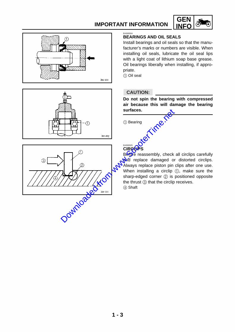
EngineEngine type Air-cooled, 2-stroke ----Induction system Reed valve ----Displacement 49 cm3 ----Cylinder arrangement Forward inclined single cylinder ----Bore × stroke 40.0 × 39.2 mm (1.57 × 1.54 in) ----Compression ratio 7.3 : 1 ----Engine idling speed 1,800 r/min ----
FuelRecommended fuel Regular unleaded gasoline ----Fuel tank capacity
Total (including reserve) 6 L (5.3 Imp qt, 6.3 US qt) ----Engine oil
Lubrication system Separate lubrication (Yamaha autolube) ----Oil type or grade Yamalube 2-cycle oil or
2-stroke engine oil--------
QuantityCapacity 1.4 L (1.23 Imp qt, 1.48 US qt) ----Air filter oil grade Foam air-filter oil or SAE 10W30SE ----
TransmissionRecommended oil Yamalube 4 (10W30) or SAE 10W30 type
SE motor oil----
Periodic oil change 0.1 L (0.09 Imp qt, 0.11 US qt) ----Total amount 0.11 L (0.1 Imp qt, 0.12 US qt) ----
Starting system type Electric and kick starter ----Spark plug
Model (manufacturer) × quantity BPR7HS (NGK) ----Spark plug gap 0.6 ~ 0.7 mm (0.02 ~ 0.03 in) ----
Cylinder headMax. warpage ---- 0.02 mm
(0.0008 in)Cylinder
Cylinder arrangement Forward inclined single cylinder ----Bore × stroke 40.0 × 39.2 mm (1.57 × 1.54 in) ----Compression ratio 7.3 : 1 ----Bore 39.993 ~ 40.012 mm (1.5745 ~ 1.5753 in) ----Max. taper ---- 0.05 mm
(0.002 in)Max. out-of-round ---- 0.05 mm
(0.002 in)
Downlo
aded
from w
ww.Sco
oterT
ime.n
et

2 - 3
SPECENGINE SPECIFICATIONS
PistonPiston-to-cylinder clearance 0.03 ~ 0.05 mm (0.0012 ~ 0.0020 in) 0.10 mm
(0.0039 in)Diameter D 39.952 ~ 39.969 mm (1.5729 ~ 1.5736 in) ----
Height H 5 mm (0.2 in) ----Oversize 1st ---- ----Oversize 2nd ---- ----Piston pin bore (in the piston)
Diameter 10.004 ~ 10.015 mm (0.3939 ~ 0.3943 in) 10.045 mm (0.3955 in)
Offset 0 mm (0 in) ----Piston pin
Outside diameter 9.996 ~ 10.000 mm (0.3935 ~ 0.3937 in) 9.976 mm (0.3928 in)
Piston-pin-to-piston-pin-bore clear-ance
0.004 ~ 0.019 mm (0.00016 ~ 0.00075 in) 0.069 mm (0.0027 in)
Piston ringTop ring
Ring type Keystone ----Dimensions (B × T) 1.2 × 1.8 mm (0.05 × 0.07 in) ----End gap (installed) 0.15 ~ 0.35 mm (0.006 ~ 0.014 in) 0.70 mm
(0.028 in)Ring side clearance 0.03 ~ 0.05 mm (0.0012 ~ 0.0020 in) 0.10 mm
(0.0039 in)2nd ring
Ring type Keystone ----Dimensions (B × T) 1.2 × 1.8 mm (0.05 × 0.07 in) ----End gap (installed) 0.15 ~ 0.35 mm (0.006 ~ 0.014 in) 0.70 mm
(0.028 in)Ring side clearance 0.03 ~ 0.05 mm (0.0012 ~ 0.0020 in) 0.10 mm
(0.0039 in)
Item Standard Limit
D
H
B
T
B
T
Downlo
aded
from w
ww.Sco
oterT
ime.n
et

2 - 4
SPECENGINE SPECIFICATIONS
Crankshaft
Width A 37.90 ~ 37.95 mm (1.492 ~ 1.494 in) ----Max. runout C ---- 0.03 mm
(0.0012 in)Big end side clearance D 0.35 ~ 0.75 mm (0.0138 ~ 0.0295 in) 1.0 mm
(0.0394 in)Big end radial clearance E 0.004 ~ 0.017 mm (0.00016 ~ 0.00067 in) ----Small end free play F 0.4 ~ 0.8 mm (0.02 ~ 0.03 in) ----
ClutchClutch type Dry, centrifugal automatic ----Clutch shoe
Thickness 4.0 mm (0.157 in) 1.0 mm (0.039 in)
Clutch shoe springFree length 29.9 mm (1.18 in) ----
KickstarterKickstarter type Ratchet ----Kickstarter pinion gear clip force 0.15 ~ 0.25 kg (0.34 ~ 0.56 lb) ----
TransmissionTransmission type V-belt automatic ----Primary reduction system Helical ----Primary reduction ratio 48/13 (3.692) ----Secondary reduction system Spur gear ----Secondary reduction ratio 42/13 (3.231) ----Operation Centrifugal automatic type ----Single speed automatic 2.183 ~ 1.050:1 ----
Air filter type Wet element ----
Item Standard Limit
CC
F
D
A
E
Downlo
aded
from w
ww.Sco
oterT
ime.n
et

2 - 5
SPECENGINE SPECIFICATIONS
CarburetorModel (manufacturer) × quantity Y14P/1 (TEIKEI) × 1 ----Throttle cable free play (at the flange of the throttle grip)
1.5 ~ 3.5 mm (0.06 ~ 0.14 in) ----
ID mark 5LY1 00 ----Main jet #64 ----Main air jet 2.0 ----Jet needle 3SOC-3/5 ----Needle jet 2.090 ----Cutaway 2.5 ----Pilot jet #46 ----Bypass 1 0.8 ----Pilot air screw turns out 1-5/8 ----Valve seat size 1.8 ----Starter jet 1 #46 ----Float height 15 ~ 17 mm (0.59 ~ 0.67 in) ----
Reed valveThickness 0.164 ~ 0.176 mm (0.0065 ~ 0.0069 in) ----Valve stopper height 7.0 ~ 7.4 mm (0.28 ~ 0.29 in) ----Valve bending limit 0.2 mm (0.008 in) ----
Autolube pumpPlunger diameter 2.62 mm (0.103 in) ----Minimum stroke 0.1 mm (0.0039 in) ----Maximum stroke 0.49 mm (0.0193 in) ----
Item Standard Limit
Downlo
aded
from w
ww.Sco
oterT
ime.n
et
2 - 6
SPECCHASSIS SPECIFICATIONS
CHASSIS SPECIFICATIONS
Item Standard Limit
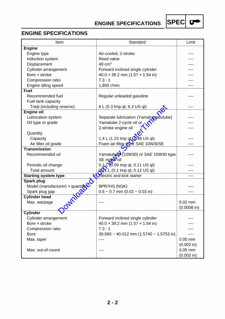
FrameFrame type Steel tube underbone ----Caster angle 25° ----Trail 71 mm (2.8 in) ----
Front wheelWheel type Panel wheel ----Rim
Size 10 × 2.15 ----Material Steel ----
Wheel travel 60 mm (2.36 in) ----Wheel runout
Max. radial wheel runout ---- 1.0 mm (0.04 in)
Max. lateral wheel runout ---- 1.0 mm (0.04 in)
Rear wheelWheel type Panel wheel ----Rim
Size 10 × 2.15 ----Material Steel ----
Wheel travel 46 mm (1.81 in) ----Wheel runout
Max. radial wheel runout ---- 1.0 mm (0.04 in)
Max. lateral wheel runout ---- 1.0 mm (0.04 in)
Front tireTire type Tubeless ----Size 80/90-10 (34J) ----Model (manufacturer) MB38/C-922 (INOUE/CHENG SHIN) ----Tire pressure (cold)
0 ~ 90 kg (0 ~ 198 lb) 150 kPa (1.50 kg/cm2, 21.8 psi) ----Min. tire tread depth ---- 1.0 mm
(0.04 in)Rear tire
Tire type Tubeless ----Size 80/90-10 (34J) ----Model (manufacturer) MB38/C-922 (INOUE/CHENG SHIN) ----Tire pressure (cold)
0 ~ 90 kg (0 ~ 198 lb) 175 kPa (1.75 kg/cm2, 25.4 psi) ----Min. tire tread depth ---- 1.0 mm
(0.04 in)
Downlo
aded
from w
ww.Sco
oterT
ime.n
et

2 - 7
SPECCHASSIS SPECIFICATIONS
Front brakeBrake type Drum brake ----Operation Right-hand operation ----Brake lever free play (at lever end) 10 ~ 20 mm (0.39 ~ 0.79 in) ----Dram brake type Leading, trailing ----
Brake drum inside diameter 110 mm (4.33 in) 110.5 mm (4.35 in)
Lining thickness 4 mm (0.16 in) 2 mm (0.08 in)
Rear brakeBrake type Drum brake ----Operation Left-hand operation ----Brake lever free play (at lever end) 10 ~ 20 mm (0.39 ~ 0.79 in) ----Drum brake type Leading, trailing ----
Brake drum inside diameter 110 mm (4.33 in) 110.5 mm (4.35 in)
Lining thickness 4 mm (0.16 in) 2 mm (0.08 in)
Front suspensionSuspension type Bottom link fork ----Front fork type Coil spring/oil damper ----Front fork travel 40 mm (1.57 in) ----Spring
Free length 156.5 mm (6.16 in) 153.4 mm (6.04 in)
Spring rate (K1) 12.8 N/mm (1.28 kgf/mm, 73.09 lb/in) ----Spring stroke (K1) 0 ~ 20 mm (0 ~ 0.79 in) ----Spring rate (K2) 30.4 N/mm (3.04 kgf/mm, 173.58 lb/in) ----Spring stroke (K2) 20 ~ 30 mm (0.79 ~ 1.18 in) ----Spring rate (K3) 67.6 N/mm (6.76 kgf/mm, 386 lb/in) ----Spring stroke (K3) 30 ~ 40 mm (1.18 ~ 1.57 in) ----
Optional spring available No ----Steering
Steering bearing type Ball and race bearing ----
Item Standard Limit
Downlo
aded
from w
ww.Sco
oterT
ime.n
et

2 - 8
SPECCHASSIS SPECIFICATIONS
Rear suspensionSuspension type Unit swing ----Rear shock absorber assembly type Coil spring/oil damper ----Rear shock absorber assembly travel 45 mm (1.77 in) ----Spring
Free length 173.5 mm (6.83 in) 170.0 mm (6.69 in)
Installed length 166.5 mm (6.56 in) ----Spring rate (K1) 34.5 N/mm (3.45 kgf/mm, 197 lb/in) ----Spring stroke (K1) 0 ~ 45 mm (0 ~ 1.77 in) ----
Optional spring available No ----
Item Standard Limit
Downlo
aded
from w
ww.Sco
oterT
ime.n
et
2 - 9
SPECELECTRICAL SPECIFICATIONS
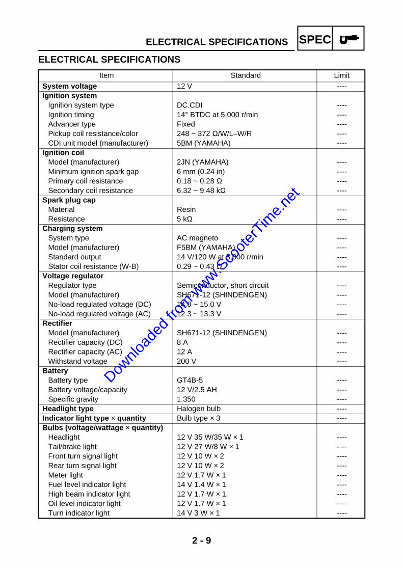
ELECTRICAL SPECIFICATIONS
Item Standard Limit
System voltage 12 V ----Ignition system
Ignition system type DC.CDI ----Ignition timing 14° BTDC at 5,000 r/min ----Advancer type Fixed ----Pickup coil resistance/color 248 ~ 372 Ω/W/L–W/R ----CDI unit model (manufacturer) 5BM (YAMAHA) ----
Ignition coilModel (manufacturer) 2JN (YAMAHA) ----Minimum ignition spark gap 6 mm (0.24 in) ----Primary coil resistance 0.18 ~ 0.28 Ω ----Secondary coil resistance 6.32 ~ 9.48 kΩ ----
Spark plug capMaterial Resin ----Resistance 5 kΩ ----
Charging systemSystem type AC magneto ----Model (manufacturer) F5BM (YAMAHA) ----Standard output 14 V/120 W at 5,000 r/min ----Stator coil resistance (W-B) 0.29 ~ 0.43 Ω ----
Voltage regulatorRegulator type Semiconductor, short circuit ----Model (manufacturer) SH671-12 (SHINDENGEN) ----No-load regulated voltage (DC) 14.0 ~ 15.0 V ----No-load regulated voltage (AC) 12.3 ~ 13.3 V ----
RectifierModel (manufacturer) SH671-12 (SHINDENGEN) ----Rectifier capacity (DC) 8 A ----Rectifier capacity (AC) 12 A ----Withstand voltage 200 V ----
BatteryBattery type GT4B-5 ----Battery voltage/capacity 12 V/2.5 AH ----Specific gravity 1.350 ----
Headlight type Halogen bulb ----Indicator light type × quantity Bulb type × 3 ----Bulbs (voltage/wattage × quantity)
Headlight 12 V 35 W/35 W × 1 ----Tail/brake light 12 V 27 W/8 W × 1 ----Front turn signal light 12 V 10 W × 2 ----Rear turn signal light 12 V 10 W × 2 ----Meter light 12 V 1.7 W × 1 ----Fuel level indicator light 14 V 1.4 W × 1 ----High beam indicator light 12 V 1.7 W × 1 ----Oil level indicator light 12 V 1.7 W × 1 ----Turn indicator light 14 V 3 W × 1 ----
Downlo
aded
from w
ww.Sco
oterT
ime.n
et
2 - 10
SPECELECTRICAL SPECIFICATIONS
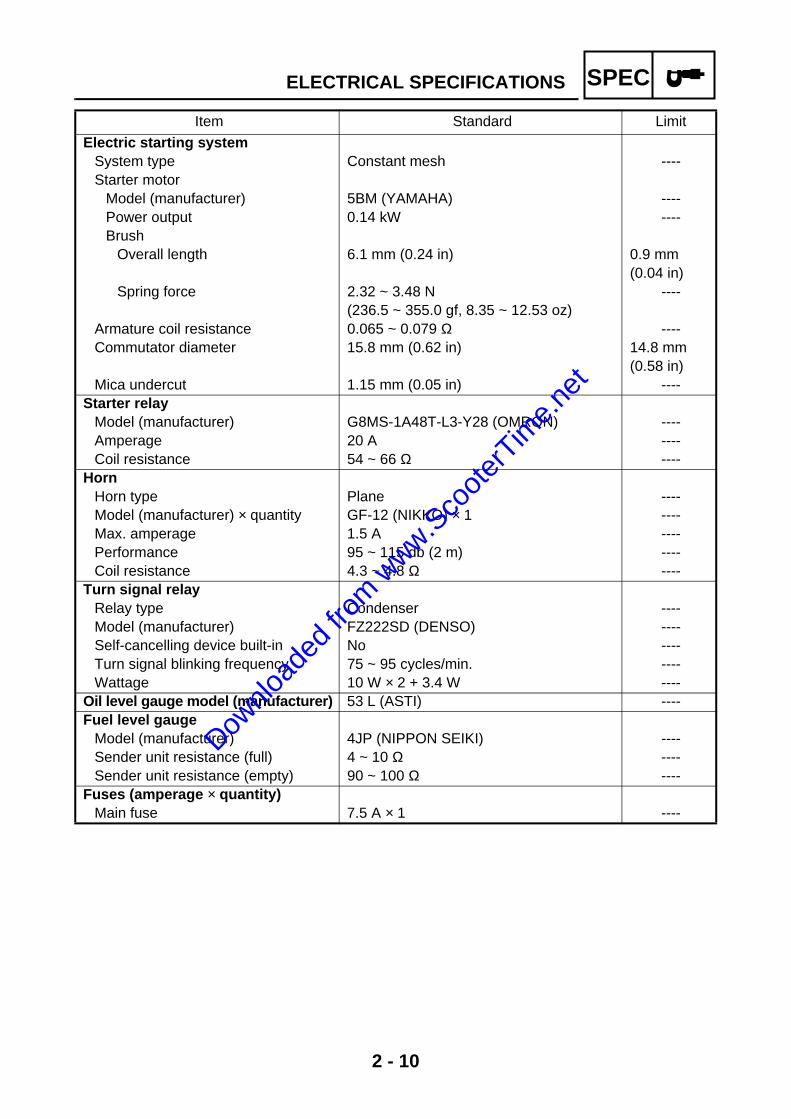
Electric starting systemSystem type Constant mesh ----Starter motor
Model (manufacturer) 5BM (YAMAHA) ----Power output 0.14 kW ----Brush
Overall length 6.1 mm (0.24 in) 0.9 mm (0.04 in)
Spring force 2.32 ~ 3.48 N (236.5 ~ 355.0 gf, 8.35 ~ 12.53 oz)
----
Armature coil resistance 0.065 ~ 0.079 Ω ----Commutator diameter 15.8 mm (0.62 in) 14.8 mm
(0.58 in)Mica undercut 1.15 mm (0.05 in) ----
Starter relayModel (manufacturer) G8MS-1A48T-L3-Y28 (OMRON) ----Amperage 20 A ----Coil resistance 54 ~ 66 Ω ----
HornHorn type Plane ----Model (manufacturer) × quantity GF-12 (NIKKO) × 1 ----Max. amperage 1.5 A ----Performance 95 ~ 115 db (2 m) ----Coil resistance 4.3 ~ 4.8 Ω ----
Turn signal relayRelay type Condenser ----Model (manufacturer) FZ222SD (DENSO) ----Self-cancelling device built-in No ----Turn signal blinking frequency 75 ~ 95 cycles/min. ----Wattage 10 W × 2 + 3.4 W ----
Oil level gauge model (manufacturer) 53 L (ASTI) ----Fuel level gauge
Model (manufacturer) 4JP (NIPPON SEIKI) ----Sender unit resistance (full) 4 ~ 10 Ω ----Sender unit resistance (empty) 90 ~ 100 Ω ----
Fuses (amperage × quantity)Main fuse 7.5 A × 1 ----
Item Standard Limit
Downlo
aded
from w
ww.Sco
oterT
ime.n
et

2 - 11
SPECCONVERSION TABLE/
GENERAL TIGHTENING TORQUE SPECIFICATIONSEAS00028
CONVERSION TABLEAll specification data in this manual are listedin SI and METRIC UNITS.Use this table to convert METRIC unit data toIMPERIAL unit data.
CONVERSION TABLE
EAS00030
GENERAL TIGHTENING TORQUE SPECIFICATIONSThis chart specifies tightening torques for stan-dard fasteners with a standard ISO threadpitch. Tightening torque specifications for spe-cial components or assemblies are providedfor each chapter of this manual. To avoidwarpage, tighten multi-fastener assemblies ina crisscross pattern and progressive stagesuntil the specified tightening torque is reached.Unless otherwise specified, tightening torquespecifications require clean, dry threads. Com-ponents should be at room temperature.
A: Width across flatsB: Thread diameter
Ex.
METRIC MULTIPLIER IMPERIAL
** mm × 0.03937 = ** in
2 mm × 0.03937 = 0.08 in
METRIC TO IMPERIAL
Tighten-ing torque
Metric unit Multiplier Imperial unit
m·kgm·kgcm·kgcm·kg
7.23386.7940.07230.8679
ft·lbin·lbft·lbin·lb
Weightkgg
2.2050.03527
lboz
Speed km/hr 0.6214 mph
Distance
kmmmcmmm
0.62143.2811.0940.39370.03937
miftydinin
Volume/Capacity
cc (cm3)cc (cm3)lt (liter)lt (liter)
0.035270.061020.87990.2199
oz (IMP liq.)cu-inqt (IMP liq.)gal (IMP liq.)
Misc.
kg/mmkg/cm2
Centigrade (°C)
55.99714.22349/5+32
lb/inpsi (lb/in2)Fahrenheit (°F)
A(nut)
B(bolt)
General tightening torques
Nm m•kg ft•lb
10 mm 6 mm 6 0.6 4.3
12 mm 8 mm 15 1.5 11
14 mm 10 mm 30 3.0 22
17 mm 12 mm 55 5.5 40
19 mm 14 mm 85 8.5 61
22 mm 16 mm 130 13.0 94
Downlo
aded
from w
ww.Sco
oterT
ime.n
et

2 - 12
SPECTIGHTENING TORQUES
TIGHTENING TORQUESENGINE TIGHTENING TORQUES
Part to be tightened Part nameThread
sizeQ’ty
Tightening torqueRemarks
Nm m·kgf ft·lb
Spark plug M14 1 20 2.0 14Cylinder head Nut M7 4 14 1.4 10Cylinder head Stud bolt M7 4 10 1.0 7Air shroud Screw M6 2 7 0.7 5.1Air shroud Screw M6 1 2 0.2 1.4Fan Screw M6 3 7 0.7 5.1Autolube pump Bolt M5 1 6 0.6 4.3Air filter Screw M6 2 9 0.9 6.5Exhaust pipe Bolt M6 2 13 1.3 9.4Muffler Bolt M8 2 28 2.8 20Muffler protector Screw M2 2 9 0.9 6.5Right crankcase Screw M6 6 9 0.9 6.5Bearing retainer (right crankcase) Screw M6 1 7 0.7 5.1Transmission cover Screw M6 5 9 0.9 6.5Sheave cover Screw M6 10 9 0.9 6.5Air filter case Screw M6 2 9 0.9 6.5Starter motor ground lead Screw M6 1 7 0.7 5.1Transmission oil drain bolt Bolt M8 1 18 1.8 13Oil filler plug M14 1 3 0.3 2.2Idle gear plate Screw M6 2 8 0.8 5.8Kickstarter crank Bolt M6 1 11 1.1 8.0Starter motor Bolt M6 2 13 1.3 9.4Clutch housing Nut M10 1 40 4.0 29Bearing retainer (transmission cover) Screw M6 1 7 0.7 5.1 LT
Primary sheave Nut M10 1 30 3.0 22Stator coil assembly Screw M6 2 8 0.8 5.8Generator rotor Nut M10 1 38 3.8 27Clutch carrier Nut M28 1 50 5.0 36Intake manifold Bolt M6 4 11 1.1 8.0
Downlo
aded
from w
ww.Sco
oterT
ime.n
et

2 - 13
SPECTIGHTENING TORQUES
CHASSIS TIGHTENING TORQUES
Part to be tightened Thread sizeTightening torque
RemarksNm m·kgf ft·lb
Engine mounting:Engine mounting bolt/nut M12 84 8.4 61Rear shock absorber and engine M8 15 1.5 11
Engine bracket and frame M10 46 4.6 33Tail reinforcement M6 10 1.0 7.2Rear shock absorber and frame M10 30 3.0 22Lower handlebar holder bracket M10 43 4.3 37Upper race M45 (BCI) 7 0.7 5.1Upper steering stem ring nut M25 (BCI) 33 3.3 24Fork and relay arm assembly M8 19 1.9 13Front shock absorber (upper) M8 19 1.9 13Front shock absorber (lower) M8 19 1.9 13Front turn signal light M12 7 0.7 5.1Fuel tank (upper) M6 7 0.7 5.1Fuel tank (lower) M6 10 1.0 7.2Fuel sender and fuel tank M5 3 0.3 2.2Seat lock assembly M6 7 0.7 5.1Carrier (upper) M6 10 1.0 7.2Carrier (lower) M8 15 1.5 11Storage box M6 8 0.8 5.8License plate bracket and rear turn signal bracket M6 12 1.2 8.7Rear turn signal bracket and tail/brake light M6 7 0.7 5.1Tail cover and rear turn signal bracket M6 12 1.2 8.7Rear turn signal light M12 7 0.7 5.1Front fender and reflector M5 3 0.3 2.2Front wheel axle M10 48 4.8 35Front brake camshaft lever M5 4 0.4 2.9Rear wheel axle nut M14 105 10.5 75Rear brake camshaft lever M6 7 0.7 5.1Rear brake pivot pin M8 16 1.6 12Speedometer cable M12 3 0.3 2.2Upper handlebar holder M6 10 1.0 7.2
Downlo
aded
from w
ww.Sco
oterT
ime.n
et

2 - 14
SPECLUBRICATION POINTS AND LUBRICANT TYPES
LUBRICATION POINTS AND LUBRICANT TYPESENGINE
Lubrication Point Symbol
Oil seal lips LS
O-rings LS
Bearings E
Piston surface E
Piston pin E
Cylinder E
Transmission case (bearing) LT
Right crankcase (bearing retainer) LT
Autolube pump LS
Starter wheel gear LS
Idle gear plate M
Secondary drive gear G
Kickstarter pinion gear LS
Drive axle M
Pump drive gear LS
Main axle G
Main axle (bearing) G
Downlo
aded
from w
ww.Sco
oterT
ime.n
et

2 - 15
SPECLUBRICATION POINTS AND LUBRICANT TYPES
CHASSIS
Lubrication Point Symbol
Oil seal lips LS
O-rings LS
Bearings LS
Speedometer drive gear LS
Front brake camshaft LS
Front brake cable LS
Throttle cable LS
Tube guide (throttle grip) inner surface LS
Upper steering stem ring nut LS
Upper bearing outer race LS
Lower bearing outer race LS
Rear brake camshaft LS
Centerstand LS
Downlo
aded
from w
ww.Sco
oterT
ime.n
et

2 - 16
SPECCABLE ROUTING
CABLE ROUTING1 Front brake cable2 Rear brake cable3 Front turn signal leads4 Fuel level gauge coupler5 Flasher relay6 Horn lead7 Throttle cable8 Main switch9 Fuel gauge 0 Speedometer cable
È Push the brake cable flange in until it contactsthe lever holder.
É Fasten the handlebar switch leads, brake lightswitch leads, meter light lead, speedometercable, brake cables and throttle cable with aplastic locking tie.
Ê Pass the left handlebar switch lead, front brakelight switch lead, and throttle cable over thecable guide.
Downlo
aded
from w
ww.Sco
oterT
ime.n
et

2 - 17
SPECCABLE ROUTING
1 Front turn signal leads (left)2 Headlight coupler3 Fuel level gauge coupler4 Flasher relay lead5 Horn lead6 Front turn signal leads (right)7 Front brake cable8 Speedometer cable9 Battery0 Rectifier/regulator couplerA CDI unit lead couplerB Fuel overflow hose
C Crankcase breather hoseD Ground leadE Carburetor overflow hoseF Rear brake cableG Throttle cable
È Fasten the turn signal light leads with the clamp.É Pass the front turn signal light leads, headlight
coupler, and horn lead through the hole of thefront turn signal light bracket.
Downlo
aded
from w
ww.Sco
oterT
ime.n
et

2 - 18
SPECCABLE ROUTING
Ê Pass the front brake cable and speedometercable through the cable guide.
Ë Pass the front brake cable and speedometercable through the hole of the front fender.
Ì Fasten the speedometer cable, front brakecable, handlebar switch leads and brake lightswitch leads with a plastic band.
Í Pass the vacuum hose and fuel hose throughthe holder. Be sure to pass the vacuum hosethrough the holder first.
Î Install the fuel tank so that the paint mark on thefuel hose is facing up.
Ï Pass the fuel overflow hose through the guide.Ð Pass the crankcase breather hose between the
crankcase and rear brake cable.Ñ Pass the carburetor overflow hose on the out-
side of the rear brake cable.
Downlo
aded
from w
ww.Sco
oterT
ime.n
et

2 - 19
SPECCABLE ROUTING
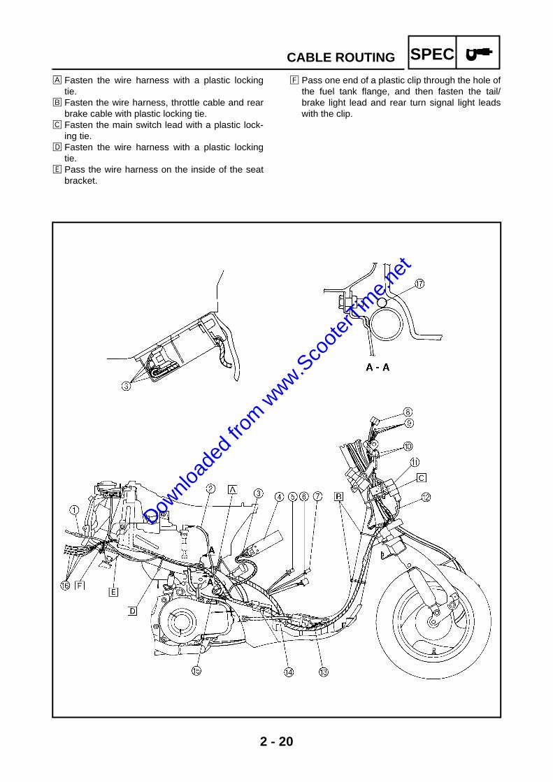
1 Tail/brake light coupler2 Oil level switch lead3 Battery leads4 Battery5 Starter motor coupler6 AC magneto coupler7 Auto choke coupler8 Headlight coupler9 Front turn signal leads0 Horn leadA Main switch lead
B Flasher relay leadC Ignition coil leadD Spark plug leadE Oil hoseF Rear turn signal leadsGWire harness
Downlo
aded
from w
ww.Sco
oterT
ime.n
et
2 - 20
SPECCABLE ROUTING
È Fasten the wire harness with a plastic lockingtie.
É Fasten the wire harness, throttle cable and rearbrake cable with plastic locking tie.
Ê Fasten the main switch lead with a plastic lock-ing tie.
Ë Fasten the wire harness with a plastic lockingtie.
Ì Pass the wire harness on the inside of the seatbracket.
Í Pass one end of a plastic clip through the hole ofthe fuel tank flange, and then fasten the tail/brake light lead and rear turn signal light leadswith the clip.
Downlo
aded
from w
ww.Sco
oterT
ime.n
et

2 - 21
SPECCABLE ROUTING
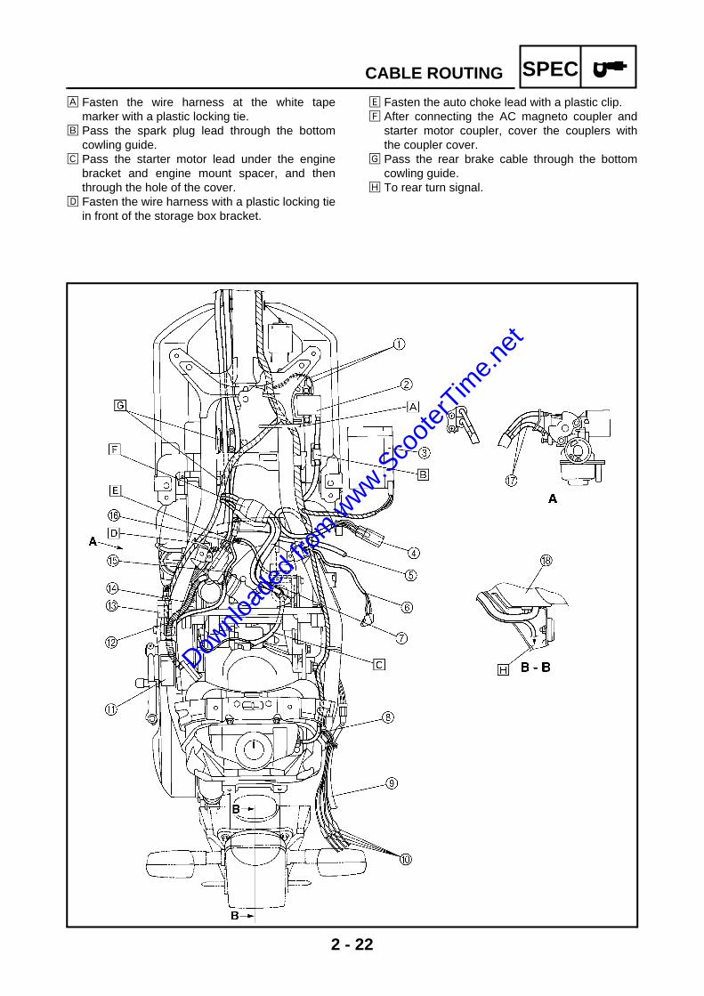
1 Ignition coil lead2 Ignition coil3 Battery4 Starter relay5 Oil hose6 Oil level switch lead7 AC magneto lead8 Fuel sender lead9 Tail/brake light lead0 Rear turn signal leads
A CDI unitB Vacuum hoseC Rectifier/regulatorD Fuel hoseE Auto choke leadF Oil delivery hoseG Throttle cableH Tail/brake light
Downlo
aded
from w
ww.Sco
oterT
ime.n
et
2 - 22
SPECCABLE ROUTING
È Fasten the wire harness at the white tapemarker with a plastic locking tie.
É Pass the spark plug lead through the bottomcowling guide.
Ê Pass the starter motor lead under the enginebracket and engine mount spacer, and thenthrough the hole of the cover.
Ë Fasten the wire harness with a plastic locking tiein front of the storage box bracket.
Ì Fasten the auto choke lead with a plastic clip.Í After connecting the AC magneto coupler and
starter motor coupler, cover the couplers withthe coupler cover.
Î Pass the rear brake cable through the bottomcowling guide.
Ï To rear turn signal.
Downlo
aded
from w
ww.Sco
oterT
ime.n
et

CHKADJ
3Downlo
aded
from w
ww.Sco
oterT
ime.n
et

CHKADJ
CHAPTER 3PERIODIC CHECKS AND ADJUSTMENTS
INTRODUCTION..............................................................................................3-1
PERIODIC MAINTENANCE AND LUBRICATION INTERVALS ....................3-1
SIDE COVERS AND FOOTREST BOARD .....................................................3-3
FRONT PANEL AND LEG SHIELD ................................................................3-5ADJUSTING THE ENGINE IDLING SPEED .............................................3-7ADJUSTING THE THROTTLE CABLE FREE PLAY ................................3-8BLEEDING THE AUTOLUBE PUMP ........................................................3-9CHECKING THE SPARK PLUG .............................................................3-10MEASURING THE COMPRESSION PRESSURE..................................3-11CHECKING THE ENGINE OIL LEVEL....................................................3-13REPLACING THE TRANSMISSION OIL ................................................3-14CLEANING THE AIR FILTER ELEMENT................................................3-16CHECKING THE CARBURETOR JOINT................................................3-17CHECKING THE FUEL AND VACUUM HOSES ....................................3-17CHECKING THE CRANKCASE BREATHER HOSE ..............................3-18CHECKING THE EXHAUST SYSTEM....................................................3-18
CHASSIS .......................................................................................................3-19ADJUSTING THE FRONT BRAKE .........................................................3-19ADJUSTING THE REAR BRAKE............................................................3-19CHECKING THE BRAKE SHOES...........................................................3-20CHECKING AND ADJUSTING THE STEERING HEAD .........................3-20CHECKING THE FRONT SHOCK ABSORBER ASSEMBLIES .............3-22CHECKING THE TIRES..........................................................................3-22CHECKING THE WHEELS .....................................................................3-25CHECKING AND LUBRICATING THE CABLES ....................................3-26LUBRICATING THE LEVERS .................................................................3-26LUBRICATING THE CENTERSTAND ....................................................3-26
ELECTRICAL SYSTEM .................................................................................3-27CHECKING AND CHARGING THE BATTERY.......................................3-27CHECKING THE FUSE...........................................................................3-34REPLACING THE HEADLIGHT BULB....................................................3-35ADJUSTING THE HEADLIGHT BEAM ...................................................3-36
Downlo
aded
from w
ww.Sco
oterT
ime.n
et

CHKADJ
Downlo
aded
from w
ww.Sco
oterT
ime.n
et
3 - 1
CHKADJ
EAS00036
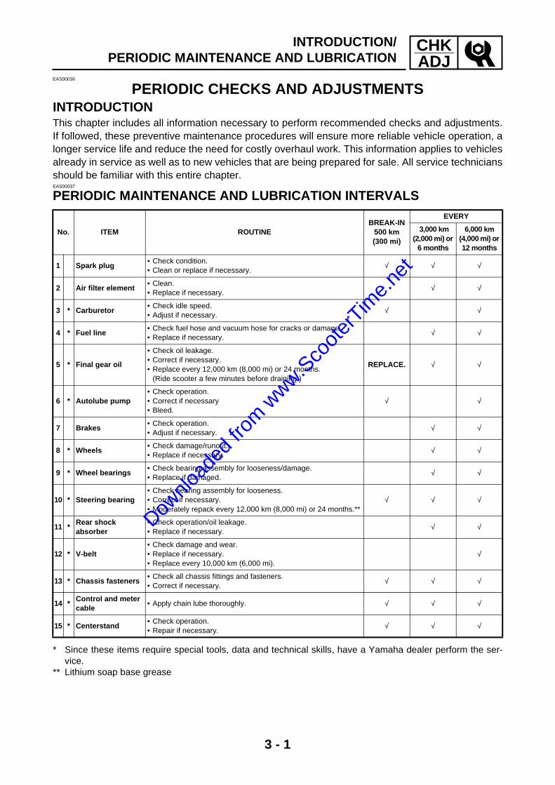
PERIODIC CHECKS AND ADJUSTMENTSINTRODUCTIONThis chapter includes all information necessary to perform recommended checks and adjustments.If followed, these preventive maintenance procedures will ensure more reliable vehicle operation, alonger service life and reduce the need for costly overhaul work. This information applies to vehiclesalready in service as well as to new vehicles that are being prepared for sale. All service techniciansshould be familiar with this entire chapter.EAS00037
PERIODIC MAINTENANCE AND LUBRICATION INTERVALS
* Since these items require special tools, data and technical skills, have a Yamaha dealer perform the ser-vice.
** Lithium soap base grease
No. ITEM ROUTINEBREAK-IN
500 km (300 mi)
EVERY
3,000 km(2,000 mi) or
6 months
6,000 km (4,000 mi) or 12 months
1 Spark plug• Check condition.• Clean or replace if necessary.
√ √ √
2 Air filter element• Clean.• Replace if necessary.
√ √
3 * Carburetor• Check idle speed.• Adjust if necessary.
√ √
4 * Fuel line• Check fuel hose and vacuum hose for cracks or damage.• Replace if necessary.
√ √
5 * Final gear oil
• Check oil leakage.• Correct if necessary.• Replace every 12,000 km (8,000 mi) or 24 months.
(Ride scooter a few minutes before draining.)
REPLACE. √ √
6 * Autolube pump• Check operation.• Correct if necessary• Bleed.
√ √
7 Brakes• Check operation.• Adjust if necessary.
√ √
8 * Wheels• Check damage/runout.• Replace if necessary.
√ √
9 * Wheel bearings• Check bearing assembly for looseness/damage.• Replace if damaged.
√ √
10 * Steering bearing• Check bearing assembly for looseness.• Correct if necessary.• Moderately repack every 12,000 km (8,000 mi) or 24 months.**
√ √ √
11 *Rear shock absorber
• Check operation/oil leakage.• Replace if necessary.
√ √
12 * V-belt• Check damage and wear.• Replace if necessary.• Replace every 10,000 km (6,000 mi).
√
13 * Chassis fasteners• Check all chassis fittings and fasteners.• Correct if necessary.
√ √ √
14 *Control and meter cable
• Apply chain lube thoroughly. √ √ √
15 * Centerstand• Check operation.• Repair if necessary.
√ √ √
INTRODUCTION/PERIODIC MAINTENANCE AND LUBRICATION
Downlo
aded
from w
ww.Sco
oterT
ime.n
et

3 - 2
CHKADJ
EAU00479
NOTE:The air filter needs more frequent service if you are riding in unusually wet or dusty areas.
EAU03903
NOTE:From 9,000 km (6,000 mi) or 18 months, repeat the maintenance intervals starting from 3,000 km(2,000 mi) or 6 months.
PERIODIC MAINTENANCE AND LUBRICATION
Downlo
aded
from w
ww.Sco
oterT
ime.n
et
3 - 3
CHKADJSIDE COVERS AND FOOTREST BOARD
EAS00038
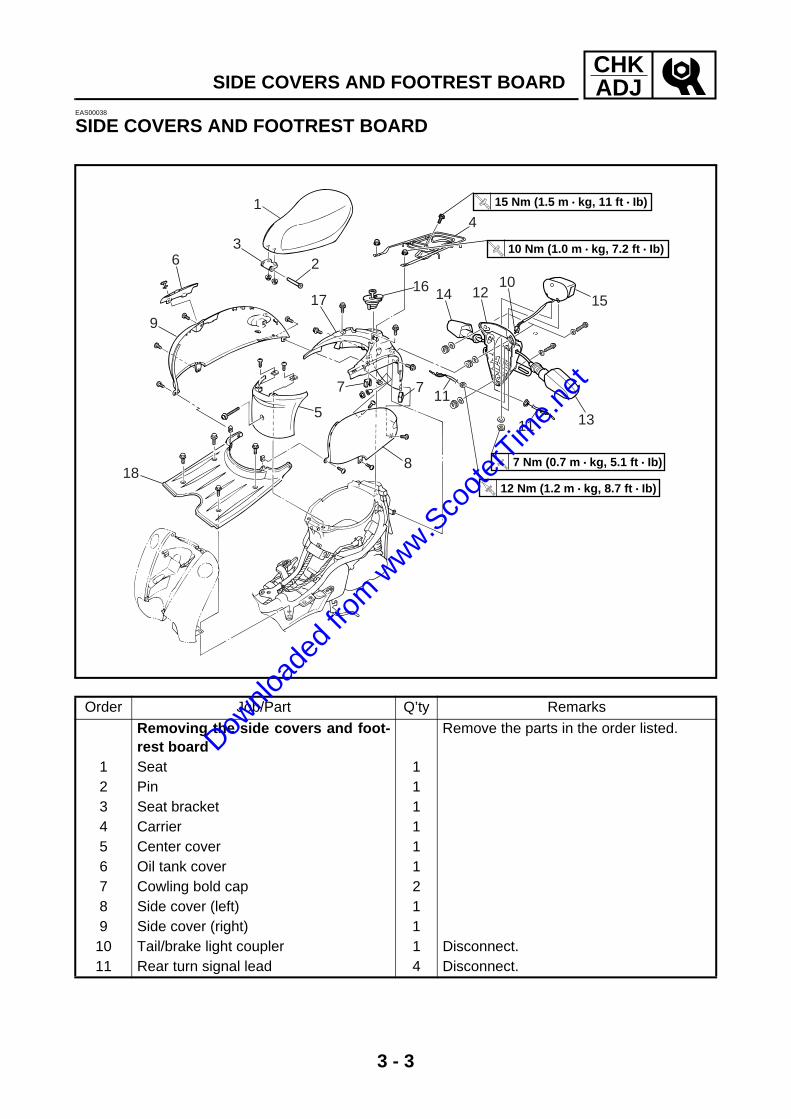
SIDE COVERS AND FOOTREST BOARD
63
9
188
11 13
1510
1214
4
1617
2
1
5
7 7
T R..
15 Nm (1.5 m • kg, 11 ft • Ib)
T R..
10 Nm (1.0 m • kg, 7.2 ft • Ib)
T R..
7 Nm (0.7 m • kg, 5.1 ft • Ib)
T R..
12 Nm (1.2 m • kg, 8.7 ft • Ib)
11
Order Job/Part Q’ty Remarks
Removing the side covers and foot-rest board
Remove the parts in the order listed.
1 Seat 12 Pin 13 Seat bracket 14 Carrier 15 Center cover 16 Oil tank cover 17 Cowling bold cap 28 Side cover (left) 19 Side cover (right) 1
10 Tail/brake light coupler 1 Disconnect.11 Rear turn signal lead 4 Disconnect.
Downlo
aded
from w
ww.Sco
oterT
ime.n
et

3 - 4
CHKADJSIDE COVERS AND FOOTREST BOARD
63
9
188
11 13
1510
1214
4
1617
2
1
5
7 7
T R..
15 Nm (1.5 m • kg, 11 ft • Ib)
T R..
10 Nm (1.0 m • kg, 7.2 ft • Ib)
T R..
7 Nm (0.7 m • kg, 5.1 ft • Ib)
T R..
12 Nm (1.2 m • kg, 8.7 ft • Ib)
11
Order Job/Part Q’ty Remarks
12 Rear turn signal bracket 113 Rear turn signal (left) 114 Rear turn signal (right) 115 Tail/brake light 116 Fuel tank cap 117 Tail cover 118 Footrest board 1
For installation, reverse the removal procedure.
Downlo
aded
from w
ww.Sco
oterT
ime.n
et

3 - 5
CHKADJFRONT PANEL AND LEG SHIELD
EAS00040
FRONT PANEL AND LEG SHIELD
19
2 345
7
13
6
810
11
12
Order Job/Part Q’ty Remarks
Removing the front panel and leg shield
Remove the parts in the order listed.
Footrest board Refer to “SIDE COVERS AND FOOT-REST BOARD”.
1 Headlight cover 12 Headlight coupler 1 Disconnect.3 Front turn signal lead 4 Disconnect.4 Horn lead 2 Disconnect.5 Front turn signal bracket 16 Horn 17 Front turn signal (left) 18 Front turn signal (right) 19 Front panel 1
10 Fuel level gauge coupler 1 Disconnect.
Downlo
aded
from w
ww.Sco
oterT
ime.n
et

3 - 6
CHKADJFRONT PANEL AND LEG SHIELD
19
2 345
7
13
6
810
11
12
Order Job/Part Q’ty Remarks
11 Fuel level gauge 112 Main switch cover 113 Leg shield 1
For installation, reverse the removal procedure.
Downlo
aded
from w
ww.Sco
oterT
ime.n
et
3 - 7
CHKADJADJUSTING THE ENGINE IDLING SPEED
EAS00053
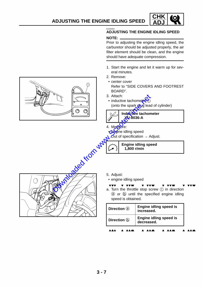
ADJUSTING THE ENGINE IDLING SPEED
NOTE:@
Prior to adjusting the engine idling speed, thecarburetor should be adjusted properly, the airfilter element should be clean, and the engineshould have adequate compression.
1. Start the engine and let it warm up for sev-eral minutes.
2. Remove: • center cover
Refer to “SIDE COVERS AND FOOTRESTBOARD”.
3. Attach: • inductive tachometer 1
(onto the spark plug lead of cylinder)
4. Measure: • engine idling speed
Out of specification → Adjust.
Inductive tachometer YU-8036-A
Engine idling speed1,800 r/min
1
5. Adjust: • engine idling speed
a. Turn the throttle stop screw 1 in directiona or b until the specified engine idlingspeed is obtained.
Direction a Engine idling speed is increased.
Direction b Engine idling speed is decreased.
1
Downlo
aded
from w
ww.Sco
oterT
ime.n
et

3 - 8
CHKADJ
ADJUSTING THE ENGINE IDLING SPEED/ADJUSTING THE THROTTLE CABLE FREE PLAY
6. Adjust: • throttle cable free play a
Refer to “ADJUSTING THE THROTTLECABLE FREE PLAY”.
Throttle cable free play (at the flange of the throttle grip)
1.5 ~ 3.5 mm (0.06 ~ 0.14 in)
EAS00058
ADJUSTING THE THROTTLE CABLE FREE PLAY
NOTE:@
Prior to adjusting the throttle cable free play,the engine idling speed should be adjusted.
1. Check: • throttle cable free play a
Out of specification → Adjust.
2. Adjust: • throttle cable free play
a. Loosen the locknut 1. b. Turn the adjusting nut 2 in direction a or
b until the specified throttle cable free playis obtained.
c. Tighten the locknut.
WARNING@
After adjusting the throttle cable free play,start the engine and turn the handlebar tothe right and to the left to ensure that thisdoes not cause the engine idling speed tochange.
Throttle cable free play (at the flange of the throttle grip)
1.5 ~ 3.5 mm (0.06 ~ 0.14 in)
Direction a Throttle cable free play is increased.
Direction b Throttle cable free play is decreased.
Downlo
aded
from w
ww.Sco
oterT
ime.n
et

3 - 9
CHKADJ
BLEEDING THE AUTOLUBE PUMP
NOTE:The Autolube pump and delivery lines must bebled on the following occasions.• Setting up a new scooter out of the crate.• Whenever the oil tank has run dry.• Whenever any portion of the engine oil sys-
tem is disconnected.
1. Remove:• center cover• side cover (right)• footrest board
Refer to “SIDE COVERS AND FOOTRESTBOARD”.
• air shroudRefer to “GENERATOR” in chapter 5.
2. Check:• oil level
Refer to “CHECKING THE ENGINE OILLEVEL”.
3. Fill:• oil tank 1 • oil tank filler cap 2
Recommended oilYamalube 2-cycle oil or 2-strokeengine oil
4. Bleed:• pump case and/or oil hose
a. Remove the bleed screw 1 b. Keep the oil running out until air bubbles
disappear.c. When air bubbles are expelled completely,
tighten the bleed screw.
BLEEDING THE AUTOLUBE PUMP
Downlo
aded
from w
ww.Sco
oterT
ime.n
et

3 - 10
CHKADJ
NOTE:• Check the bleed screw gasket, and if dam-
aged, replace with a new one.• Place a oil pan under the autolube pump to
catch oil.
5. Install:• air shroud
Refer to “GENERATOR AND AUTOLUBEPUMP” in chapter 5.
• footrest board• side cover (right)• center cover
Refer to “SIDE COVERS AND FOOTRESTBOARD”.
EAS00060
CHECKING THE SPARK PLUG1. Disconnect: • spark plug cap
2. Remove: • spark plug
CAUTION:@
Before removing the spark plug, blow awayany dirt accumulated in the spark plug wellwith compressed air to prevent it from fall-ing into the cylinder.
3. Check: • spark plug type
Incorrect → Change.
Spark plug type (manufacturer) BPR7HS (NGK)
BLEEDING THE AUTOLUBE PUMP/CHECKING THE SPARK PLUG
Downlo
aded
from w
ww.Sco
oterT
ime.n
et

3 - 11
CHKADJ
CHECKING THE SPARK PLUG/MEASURING THE COMPRESSION PRESSURE
4. Check: • electrodes 1
Damage/wear → Replace the spark plug. • insulator 2
Abnormal color → Replace the spark plug. Normal color is medium-to-light tan.
5. Clean: • spark plug
(with a spark plug cleaner or wire brush)6. Measure: • spark plug gap a
(with a wire gauge) Out of specification → Regap.
7. Install: • spark plug
NOTE:@
Before installing the spark plug, clean thespark plug and gasket surface.
8. Connect: • spark plug cap
Spark plug gap 0.6 ~ 0.7 mm (0.02 ~ 0.03 in)
T R..
20 Nm (2.0 m · kg, 14 ft · lb)
EAS00067
MEASURING THE COMPRESSION PRESSURE
NOTE:@
Insufficient compression pressure will result ina loss of performance.
1. Start the engine, warm it up for several min-utes, and then turn it off.
2. Remove:• center cover• footrest board
Refer to “SIDE COVERS AND FOOTRESTBOARD”.
3. Disconnect: • spark plug cap
4. Remove: • spark plug
Downlo
aded
from w
ww.Sco
oterT
ime.n
et

3 - 12
CHKADJMEASURING THE COMPRESSION PRESSURE
CAUTION:@
Before removing the spark plug, use com-pressed air to blow away any dirt accumu-lated in the spark plug well to prevent itfrom falling into the cylinder.
5. Install: • compression gauge 1
Compression gaugeYU-33223
1
6. Measure: • compression pressure
Out of specification → Refer to steps (c)and (d).
a. Set the main switch to “ON”. b. With the throttle wide open, crank the
engine until the reading on the compressiongauge stabilizes.
WARNING@
To prevent sparking, ground the spark pluglead before cranking the engine.
c. If the compression pressure is above themaximum specification, check the cylinderhead and piston crown for carbon deposits. Carbon deposits → Eliminate.
Compression pressure (at sea level)
Minimum600 kPa (6.0 kg/cm, 85.3 psi)
Standard800 kPa (8.0 kg/cm, 113.8 psi)
Maximum1,000 kPa (10.0 kg/cm, 142.2 psi)
Downlo
aded
from w
ww.Sco
oterT
ime.n
et

3 - 13
CHKADJ
MEASURING THE COMPRESSION PRESSURE/CHECKING THE ENGINE OIL LEVEL
d. If the compression pressure is below theminimum specification, squirt a few drops ofoil into the cylinder and measure again. Refer to the following table.
7. Install: • spark plug
8. Connect: • spark plug cap
Compression pressure (with oil applied into the cylinder)
Reading Diagnosis
Higher than with-out oil
Piston wear or damage → Repair.
Same as without oil
Piston ring(s), cyl-inder head gasket or piston possibly defective → Repair.
T R..
20 Nm (2.0 m · kg, 14 ft · lb)
EAS00072
CHECKING THE ENGINE OIL LEVEL1. Stand the scooter on a level surface.
NOTE:• Place the scooter on a suitable stand.• Make sure the scooter is upright.
2. Check:• oil level warning light 1
Refer to “SIGNAL SYSTEM” in chapter 7.
Downlo
aded
from w
ww.Sco
oterT
ime.n
et

3 - 14
CHKADJ
3. Remove:• oil tank cover
Refer to “SIDE COVERS AND FOOTREST-BOARD”.
• oil tank cap 1
4. Fill:• engine oil
Make sure the engine oil is at the specifiedlevel. Fill with oil as necessary.
Recommended oilYamalube 2-cycle oil or 2-strokeengine oil
REPLACING THE TRANSMISSION OIL1. Stand the scooter on a level surface.
NOTE:• Place the scooter on a suitable stand.• Make sure the scooter is upright.
2. Start the engine, warm it up for several min-utes, and then turn it off.
3. Place a container under the transmission oildrain bolt.
4. Remove:• oil filler plug 1 • O-ring 2
1
1
2
CHECKING THE ENGINE OIL LEVEL/REPLACING THE TRANSMISSION OIL
Downlo
aded
from w
ww.Sco
oterT
ime.n
et

3 - 15
CHKADJ
5. Remove:• transmission oil drain bolt 1 • gasket
1
6. Drain:• transmission oil
(completely from the transmission case)7. Check:• O-ring
Damage → Replace.
8. Install:• gasket 1 • transmission oil drain bolt 2
New
12
New
T R..
18 Nm (1.8 m · kg, 13 ft · lb)
9. Fill:• crankcase
(with the specified amount of the recom-mended transmission oil)
Recommended oilSAE 10W30SE
Total amount0.11 L (0.1 Imp qt, 0.12 US qt)
10.Install:• O-ring• oil filler plug
REPLACING THE TRANSMISSION OIL
Downlo
aded
from w
ww.Sco
oterT
ime.n
et

3 - 16
CHKADJCLEANING THE AIR FILTER ELEMENT
EAS00089
CLEANING THE AIR FILTER ELEMENT
NOTE:@
On the bottom of the air filter case is a checkhose 1. If dust or water or both collects in thishose, clean the air filter element and air filtercase.
1. Remove: • footrest board
Refer to “SIDE COVERS AND FOOTRESTBOARD”.
2. Remove: • air filter case cover 1 • air filter element 2
3. Clean: • air filter element
(with solvent)
WARNING@
Never use low flash point solvents, such asgasoline, to clean the air filter element.Such solvents may cause a fire or an explo-sion.
NOTE:@
After cleaning, gently squeeze the air filter ele-ment to remove the excess solvent.
CAUTION:@
Do not twist the air filter element whensqueezing it.
4. Check: • air filter element 1
Damage → Replace.5. Apply the recommended oil to the entire
surface of the air filter element and squeezeout the excess oil. The air filter elementshould be wet but not dripping.
Recommended oilFoam air filter oil or Yamalube 2-cycle oil or 2-strokeengine oil
Downlo
aded
from w
ww.Sco
oterT
ime.n
et

3 - 17
CHKADJ
CLEANING THE AIR FILTER ELEMENT/CHECKING THE CARBURETOR JOINT/
CHECKING THE FUEL AND VACUUM HOSES
6. Install: • air filter element • air filter case cover
CAUTION:@
Never operate the engine without the air fil-ter element installed. Unfiltered air willcause rapid wear of engine parts and maydamage the engine. Operating the enginewithout the air filter element will also affectthe carburetor tuning, leading to poorengine performance and possible overheat-ing.
7. Install: • footrest board
Refer to “SIDE COVERS AND FOOTRESTBOARD”.
EAS00094
CHECKING THE CARBURETOR JOINT1. Remove: • center cover • footrest board
Refer to “SIDE COVERS AND FOOTRESTBOARD”.
• air filter case2. Check: • carburetor joint 1
Cracks/damage → Replace. Refer to “CARBURETOR” in chapter 6.
3. Install: • air filter case• footrest board• center cover
Refer to “SIDE COVERS AND FOOTRESTBOARD”.
EAS00096
CHECKING THE FUEL AND VACUUM HOSESThe following procedure applies to all of thefuel and vacuum hoses.1. Remove: • side cover (left)
Refer to “SIDE COVERS AND FOOTRESTBOARD”.
Downlo
aded
from w
ww.Sco
oterT
ime.n
et
3 - 18
CHKADJ
CHECKING THE FUEL AND VACUUM HOSES/CHECKING THE CRANKCASE BREATHER HOSE/
CHECKING THE EXHAUST SYSTEM
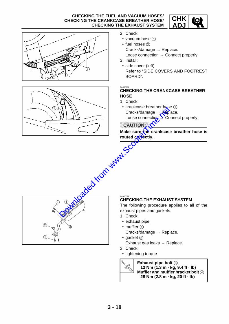
2. Check: • vacuum hose 1 • fuel hoses 2
Cracks/damage → Replace. Loose connection → Connect properly.
3. Install: • side cover (left)
Refer to “SIDE COVERS AND FOOTRESTBOARD”.
EAS00098
CHECKING THE CRANKCASE BREATHER HOSE1. Check: • crankcase breather hose 1
Cracks/damage → Replace. Loose connection → Connect properly.
CAUTION:@
Make sure the crankcase breather hose isrouted correctly.
EAS00099
CHECKING THE EXHAUST SYSTEMThe following procedure applies to all of theexhaust pipes and gaskets.1. Check: • exhaust pipe • muffler 1
Cracks/damage → Replace. • gasket 2
Exhaust gas leaks → Replace.2. Check: • tightening torque
T R..
Exhaust pipe bolt 3 13 Nm (1.3 m · kg, 9.4 ft · lb)
Muffler and muffler bracket bolt 4 28 Nm (2.8 m · kg, 20 ft · lb)
14
2
3
Downlo
aded
from w
ww.Sco
oterT
ime.n
et
3 - 19
CHKADJ
ADJUSTING THE FRONT BRAKE/ADJUSTING THE REAR BRAKE
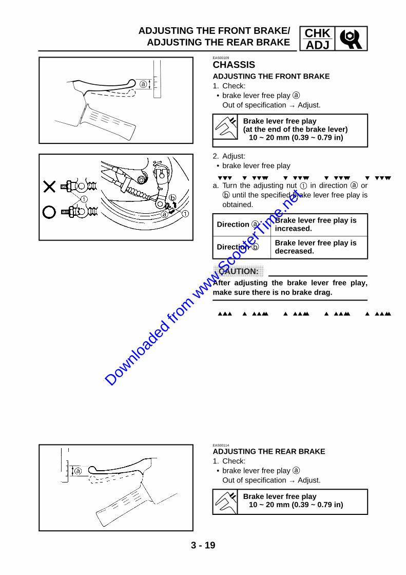
EAS00109
CHASSISADJUSTING THE FRONT BRAKE1. Check: • brake lever free play a
Out of specification → Adjust.
Brake lever free play (at the end of the brake lever)
10 ~ 20 mm (0.39 ~ 0.79 in)
2. Adjust: • brake lever free play
a. Turn the adjusting nut 1 in direction a orb until the specified brake lever free play isobtained.
CAUTION:@
After adjusting the brake lever free play,make sure there is no brake drag.
Direction a Brake lever free play is increased.
Direction b Brake lever free play is decreased.
EAS00114
ADJUSTING THE REAR BRAKE1. Check: • brake lever free play a
Out of specification → Adjust.
Brake lever free play 10 ~ 20 mm (0.39 ~ 0.79 in)
Downlo
aded
from w
ww.Sco
oterT
ime.n
et

3 - 20
CHKADJ
ADJUSTING THE REAR BRAKE/CHECKING THE BRAKE SHOES/
CHECKING AND ADJUSTING THE STEERING HEAD
2. Adjust: • brake lever free play
a. Turn the adjusting nut 1 in direction a orb until the specified brake lever free play isobtained.
CAUTION:@
After adjusting the brake lever free play,make sure there is no brake drag.
Direction a Brake lever free play is increased.
Direction b Brake lever free play is decreased.
EAS00127
CHECKING THE BRAKE SHOES1. Operate the brake. 2. Check: • wear indicator 1
Reaches the wear limit line 2 → Replacethe brake shoes as a set. Refer to “FRONT WHEEL AND BRAKE”and “REAR WHEEL AND BRAKE” in chap-ter 4.
È Front brake É Rear brake
È
É
EAS00148
CHECKING AND ADJUSTING THE STEERING HEAD1. Stand the scooter on a level surface.
WARNING@
Securely support the scooter so that thereis no danger of it falling over.
Downlo
aded
from w
ww.Sco
oterT
ime.n
et

3 - 21
CHKADJCHECKING AND ADJUSTING THE STEERING HEAD
NOTE:@
Place the scooter on a suitable stand so thatthe front wheel is elevated.
2. Check: • steering head
Grasp the bottom of the front fork legs andgently rock the front fork. Binding/looseness → Adjust the steering head.
3. Remove: • center cover• footrest board
Refer to “SIDE COVERS AND FOOTRESTBOARD”.
• leg shieldRefer to “FRONT PANEL AND LEGSHIELD”.
4. Adjust: • steering head
a. Remove the upper steering stem ring nut.b. Loosen the upper race 1 and then tighten it
to specification with the steering nut wrench(45 mm) 2.
NOTE:@
Set the torque wrench at a right angle to thesteering stem ring nut wrench.
c. Hold the upper race with a steering nutwrench (45 mm) and tighten the upper steer-ing stem ring nut 3 with a steering nutwrench 4.
d. Check the steering head for looseness orbinding by turning the front fork all the wayin both directions.
Steering nut wrench (45 mm)YU-01444
T R..
Upper race7 Nm (0.7 m · kg, 5.1 ft · lb)
Steering nut wrenchYU-33975
T R..
Upper steering stem ring nut 33 Nm (3.3 m · kg, 24 ft · lb)
2
1
3
4
Downlo
aded
from w
ww.Sco
oterT
ime.n
et

3 - 22
CHKADJ
CHECKING AND ADJUSTING THE STEERING HEAD/CHECKING THE FRONT SHOCK ABSORBER ASSEMBLIES/
CHECKING THE TIRES
5. Install:• Steering shaft bolt 5
6. Install:• leg shield
Refer to “FRONT PANEL AND LEG SHIELD”.• footrest board• center cover
Refer to “SIDE COVERS AND FOOTRESTBOARD”.
5
T R..
42 Nm (4.2 m · kg, 30 ft · lb)
EAS00151
CHECKING THE FRONT SHOCK ABSORBER ASSEMBLIES1. Stand the scooter on a level surface.
WARNING@
Securely support the scooter so that thereis no danger of it falling over.
2. Hold the scooter upright and apply the frontbrake.
3. Check: • front shock absorber operation
Push down hard on the handlebar severaltimes and check if the front fork reboundssmoothly. Rough movement → Repair. Refer to “FRONT SHOCK ABSORBERASSEMBLIES” in chapter 4.
EAS00163
CHECKING THE TIRESThe following procedure applies to both of thetires.1. Measure: • tire pressure
Out of specification → Regulate.
Downlo
aded
from w
ww.Sco
oterT
ime.n
et

3 - 23
CHKADJCHECKING THE TIRES
WARNING@
• The tire pressure should only be checkedand regulated when the tire temperatureequals the ambient air temperature.
• The tire pressure and the suspensionmust be adjusted according to the totalweight (including cargo, rider and acces-sories) and the anticipated riding speed.
• Operation of an overloaded scooter couldcause tire damage, an accident or aninjury.
NEVER OVERLOAD THE SCOOTER.
* total of cargo, rider and accessories
WARNING@
It is dangerous to ride with a worn-out tire.When the tire tread reaches the wear limit,replace the tire immediately.
Basic weight (with oil and a full fuel tank)
74 kg (163 lb)
Maximum load* 76 kg (168 lb)
Cold tire pressure
Front Rear
150 kPa (1.50 kgf/cm 2,21.8 psi)
175 kPa (1.75 kgf/cm 2,25.4 psi)
2. Check: • tire surfaces
Damage/wear → Replace the tire.
1 Tire tread depth2 Side wall3Wear indicator
Minimum tire tread depth1.0 mm (0.04 in)
Downlo
aded
from w
ww.Sco
oterT
ime.n
et

3 - 24
CHKADJCHECKING THE TIRES
WARNING@
• Do not use a tubeless tire on a wheeldesigned only for tube tires to avoid tirefailure and personal injury from suddendeflation.
• When using tube tires, be sure to installthe correct tube.
• Always replace a new tube tire and a newtube as a set.
• To avoid pinching the tube, make sure thewheel rim band and tube are centered inthe wheel groove.
• Patching a punctured tube is not recom-mended. If it is absolutely necessary todo so, use great care and replace the tubeas soon as possible with a good qualityreplacement.
È Tire É Wheel
• After extensive tests, the tires listedbelow have been approved by YamahaMotor Co., Ltd. for this model. The frontand rear tires should always be by thesame manufacturer and of the samedesign. No guarantee concerning han-dling characteristics can be given if a tirecombination other than one approved byYamaha is used on this scooter.
Tube wheel Tube tire only
Tubeless wheel Tube or tubeless tire
È É
Front tire
Manufacturer Model Size
INOUE MB38 80/90-10 (34J)
CHENG SHIN C-922 80/90-10 (34J)
Downlo
aded
from w
ww.Sco
oterT
ime.n
et
3 - 25
CHKADJCHECKING THE TIRES/CHECKING THE WHEELS
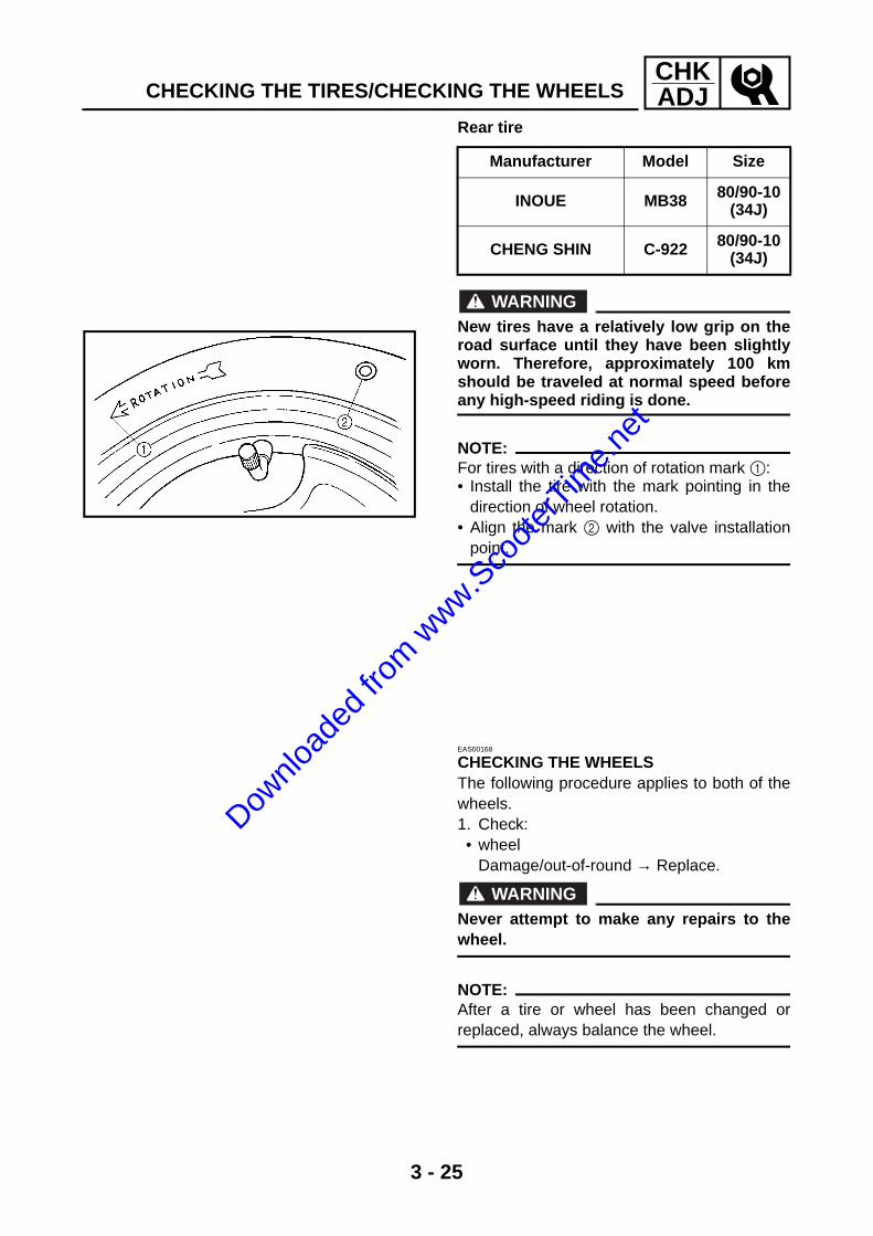
Rear tire
WARNING@
New tires have a relatively low grip on theroad surface until they have been slightlyworn. Therefore, approximately 100 kmshould be traveled at normal speed beforeany high-speed riding is done.
NOTE:@
For tires with a direction of rotation mark 1: • Install the tire with the mark pointing in the
direction of wheel rotation. • Align the mark 2 with the valve installation
point.
Manufacturer Model Size
INOUE MB38 80/90-10 (34J)
CHENG SHIN C-922 80/90-10 (34J)
EAS00168
CHECKING THE WHEELSThe following procedure applies to both of thewheels.1. Check: • wheel
Damage/out-of-round → Replace.
WARNING@
Never attempt to make any repairs to thewheel.
NOTE:@
After a tire or wheel has been changed orreplaced, always balance the wheel.
Downlo
aded
from w
ww.Sco
oterT
ime.n
et

3 - 26
CHKADJ
CHECKING AND LUBRICATING THE CABLES/LUBRICATING THE LEVERS/LUBRICATING THE CENTERSTAND
EAS00170
CHECKING AND LUBRICATING THE CABLESThe following procedure applies to all of thecable sheaths and cables.
WARNING@
Damaged cable sheaths may cause thecable to corrode and interfere with itsmovement. Replace damaged cablesheaths and cables as soon as possible.
1. Check: • cable sheath
Damage → Replace.2. Check: • cable operation
Rough movement → Lubricate.
NOTE:@
Hold the cable end upright and pour a fewdrops of lubricant into the cable sheath or usea suitable lubricating device.
Recommended lubricant Engine oil or a suitable cable lubricant
EAS00171
LUBRICATING THE LEVERSLubricate the pivoting point and metal-to-metalmoving parts of the levers.
Recommended lubricant Lithium soap base grease
EAS00173
LUBRICATING THE CENTERSTANDLubricate the pivoting point and metal-to-metalmoving parts of the centerstand.
Recommended lubricant Lithium soap base grease
Downlo
aded
from w
ww.Sco
oterT
ime.n
et

3 - 27
CHKADJCHECKING AND CHARGING THE BATTERY
EAS00179
ELECTRICAL SYSTEMCHECKING AND CHARGING THE BATTERY
WARNING@
Batteries generate explosive hydrogen gasand contain electrolyte which is made ofpoisonous and highly caustic sulfuric acid. Therefore, always follow these preventivemeasures: • Wear protective eye gear when handling
or working near batteries. • Charge batteries in a well-ventilated area. • Keep batteries away from fire, sparks or
open flames (e.g., welding equipment,lighted cigarettes).
• DO NOT SMOKE when charging or han-dling batteries.
• KEEP BATTERIES AND ELECTROLYTEOUT OF REACH OF CHILDREN.
• Avoid bodily contact with electrolyte as itcan cause severe burns or permanent eyeinjury.
FIRST AID IN CASE OF BODILY CONTACT: EXTERNAL • Skin — Wash with water. • Eyes — Flush with water for 15 minutes
and get immediate medical attention. INTERNAL • Drink large quantities of water or milk fol-
lowed with milk of magnesia, beaten eggor vegetable oil. Get immediate medicalattention.
CAUTION:@
Charging time, charging amperage andcharging voltage for an MF battery are dif-ferent from those of conventional batteries.The MF battery should be charged asexplained in the charging method illustra-tions. If the battery is overcharged, theelectrolyte level will drop considerably.Therefore, take special care when chargingthe battery.
Downlo
aded
from w
ww.Sco
oterT
ime.n
et
3 - 28
CHKADJCHECKING AND CHARGING THE BATTERY
NOTE:@
Since MF batteries are sealed, it is not possi-ble to check the charge state of the battery bymeasuring the specific gravity of the electro-lyte. Therefore, the charge of the battery has tobe checked by measuring the voltage at thebattery terminals.
1. Remove: • center cover
Refer to “SIDE COVERS AND FOOTRESTBOARD”.
• battery boxRefer to “ENGINE REMOVAL” in chapter 5.
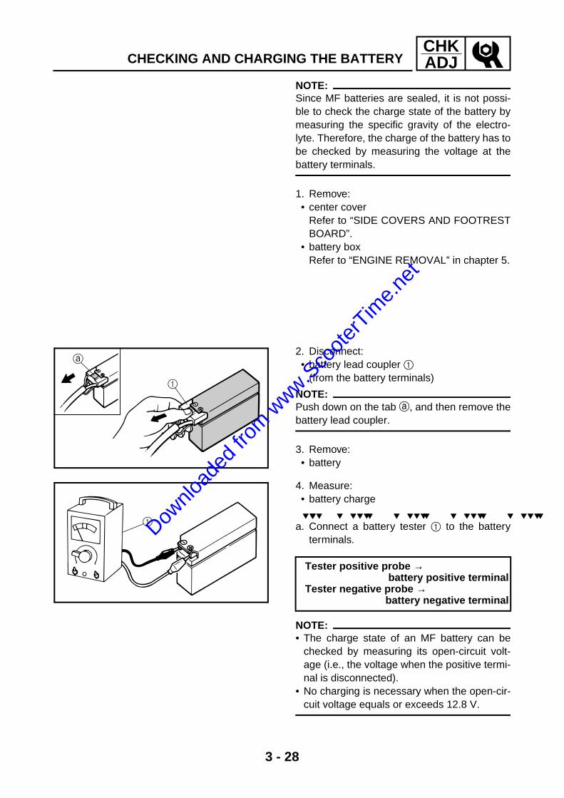
2. Disconnect: • battery lead coupler 1
(from the battery terminals)
NOTE:Push down on the tab a, and then remove thebattery lead coupler.
3. Remove: • battery
1
4. Measure: • battery charge
a. Connect a battery tester 1 to the batteryterminals.
NOTE:@
• The charge state of an MF battery can bechecked by measuring its open-circuit volt-age (i.e., the voltage when the positive termi-nal is disconnected).
• No charging is necessary when the open-cir-cuit voltage equals or exceeds 12.8 V.
Tester positive probe → battery positive terminal
Tester negative probe → battery negative terminal
1Downlo
aded
from w
ww.Sco
oterT
ime.n
et
3 - 29
CHKADJCHECKING AND CHARGING THE BATTERY
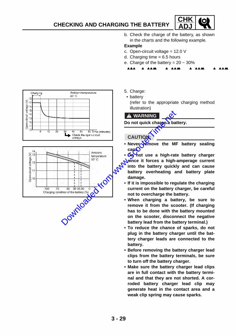
b. Check the charge of the battery, as shownin the charts and the following example.
Examplec. Open-circuit voltage = 12.0 V d. Charging time = 6.5 hours e. Charge of the battery = 20 ~ 30%
5. Charge: • battery
(refer to the appropriate charging methodillustration)
WARNING@
Do not quick charge a battery.
CAUTION:@
• Never remove the MF battery sealingcaps.
• Do not use a high-rate battery chargersince it forces a high-amperage currentinto the battery quickly and can causebattery overheating and battery platedamage.
• If it is impossible to regulate the chargingcurrent on the battery charger, be carefulnot to overcharge the battery.
• When charging a battery, be sure toremove it from the scooter. (If charginghas to be done with the battery mountedon the scooter, disconnect the negativebattery lead from the battery terminal.)
• To reduce the chance of sparks, do notplug in the battery charger until the bat-tery charger leads are connected to thebattery.
• Before removing the battery charger leadclips from the battery terminals, be sureto turn off the battery charger.
• Make sure the battery charger lead clipsare in full contact with the battery termi-nal and that they are not shorted. A cor-roded battery charger lead clip maygenerate heat in the contact area and aweak clip spring may cause sparks.
Downlo
aded
from w
ww.Sco
oterT
ime.n
et
3 - 30
CHKADJCHECKING AND CHARGING THE BATTERY
• If the battery becomes hot to the touch atany time during the charging process,disconnect the battery charger and let thebattery cool before reconnecting it. Hotbatteries can explode!
• As shown in the following illustration, theopen-circuit voltage of an MF battery sta-bilizes about 30 minutes after charginghas been completed. Therefore, wait 30minutes after charging is completedbefore measuring the open-circuit volt-age.
Downlo
aded
from w
ww.Sco
oterT
ime.n
et
3 - 31
CHKADJ
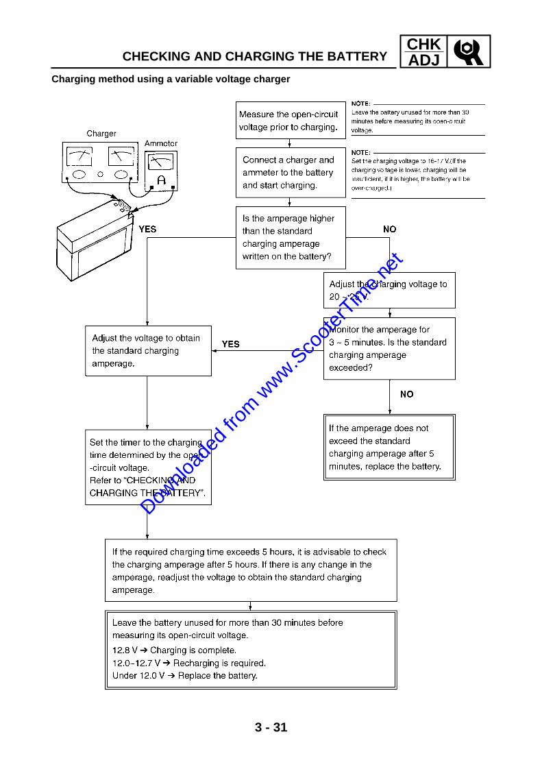
Charging method using a variable voltage charger
CHECKING AND CHARGING THE BATTERY
Downlo
aded
from w
ww.Sco
oterT
ime.n
et

3 - 32
CHKADJ
Charging method using a constant voltage charger
CHECKING AND CHARGING THE BATTERY
Downlo
aded
from w
ww.Sco
oterT
ime.n
et

3 - 33
CHKADJ
6. Install: • battery
7. Connect: • battery lead coupler
(to the battery terminals)8. Check: • battery terminals
Dirt → Clean with a wire brush. Loose connection → Connect properly.
9. Lubricate: • battery terminal
10.Install: • battery box
Refer to “ENGINE REMOVAL” in chapter 5.• center cover
Refer to “SIDE COVERS AND FOOTRESTBOARD”.
Recommended lubricant Dielectric grease
CHECKING AND CHARGING THE BATTERY
Downlo
aded
from w
ww.Sco
oterT
ime.n
et

3 - 34
CHKADJCHECKING THE FUSE
EAS00181
CHECKING THE FUSE
CAUTION:@
To avoid a short circuit, always set themain switch to “OFF” when checking orreplacing a fuse.
1. Remove: • center cover
Refer to “SIDE COVERS AND FOOTRESTBOARD”.
• batteryRefer to “ENGINE REMOVAL” in chapter 5.
2. Check: • continuity
a. Connect the pocket tester to the fuse andcheck the continuity.
NOTE:@
Set the pocket tester selector to “Ω × 1”.
b. If the pocket tester indicates “∞”, replacethe fuse.
Pocket tester YU-03112
3. Replace: • blown fuse
a. Set the main switch to “OFF”. b. Install a new fuse of the correct amperage. c. Set on the switches to verify if the electrical
circuit is operational. d. If the fuse immediately blows again, check
the electrical circuit.
Items Amperage rating Q’ty
Main fuse 7.5 A 1
Downlo
aded
from w
ww.Sco
oterT
ime.n
et
3 - 35
CHKADJCHECKING THE FUSE/REPLACING THE HEADLIGHT
WARNING@
Never use a fuse with an amperage ratingother than that specified. Improvising orusing a fuse with the wrong amperage rat-ing may cause extensive damage to theelectrical system, cause the lighting andignition systems to malfunction and couldpossibly cause a fire.
4. Install: • battery
Refer to “ENGINE REMOVAL” in chapter 4.• center cover
Refer to “SIDE COVERS AND FOOTRESTBOARD”.
EAS00182
REPLACING THE HEADLIGHT BULB1. Remove:• Headlight cover
Refer to “FRONT PANEL AND LEGSHIELD”.
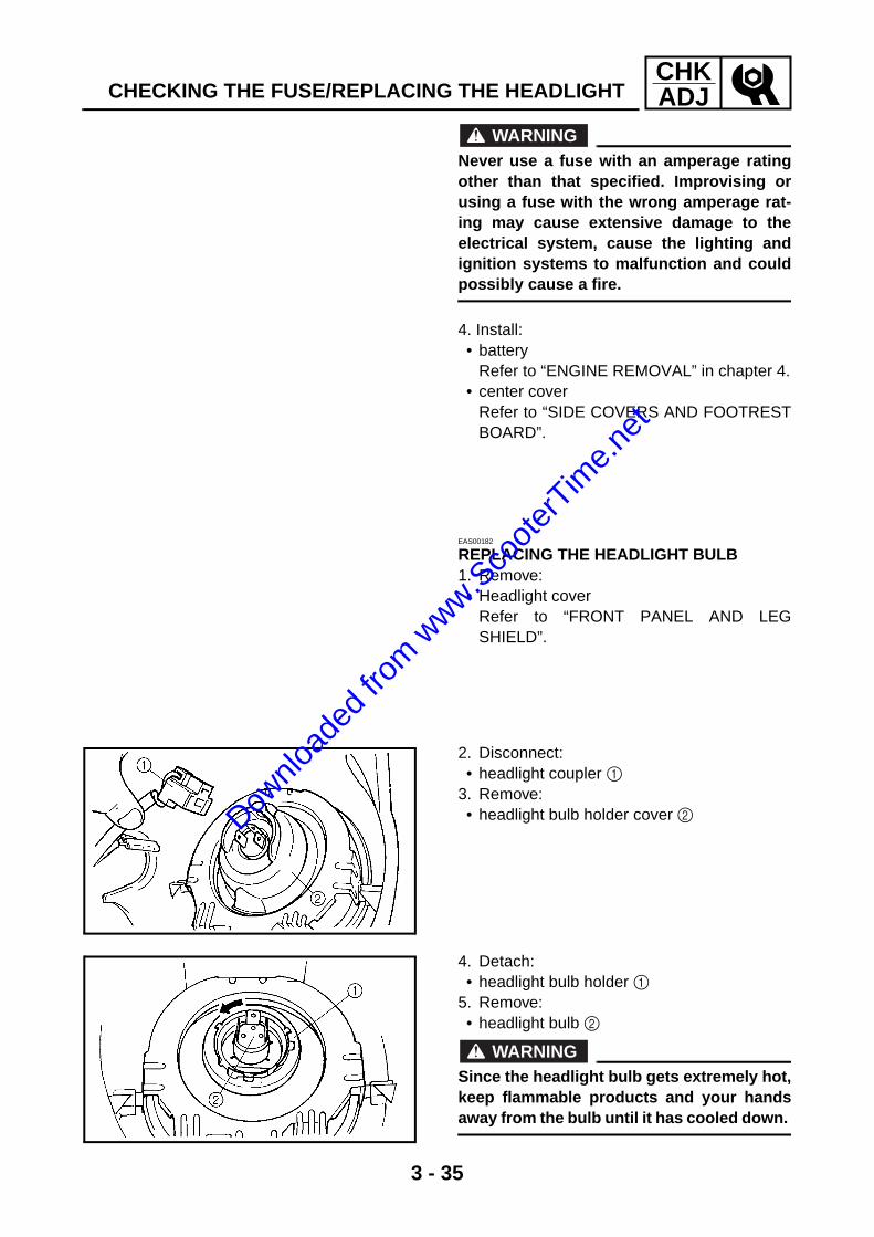
2. Disconnect: • headlight coupler 1
3. Remove:• headlight bulb holder cover 2
4. Detach: • headlight bulb holder 1
5. Remove: • headlight bulb 2
WARNING@
Since the headlight bulb gets extremely hot,keep flammable products and your handsaway from the bulb until it has cooled down.
Downlo
aded
from w
ww.Sco
oterT
ime.n
et

3 - 36
CHKADJ
REPLACING THE HEADLIGHT BULB/ADJUSTING THE HEADLIGHT BEAM
6. Install: • headlight bulb
Secure the new headlight bulb with theheadlight bulb holder.
CAUTION:@
Avoid touching the glass part of the head-light bulb to keep it free from oil, otherwisethe transparency of the glass, the life of thebulb and the luminous flux will beadversely affected. If the headlight bulbgets soiled, thoroughly clean it with a clothmoistened with alcohol or lacquer thinner.
7. Attach: • headlight bulb holder
8. Install: • headlight bulb holder cover
9. Connect:• headlight coupler
10.Install: • Headlight cover
Refer to “FRONT PANEL AND LEGSHILD”.
New
EAS00184
ADJUSTING THE HEADLIGHT BEAM1. Adjust: • headlight beam (vertically)
a. Loosen the adjusting screw 1 and push theheadlight lens unit in direction a or b.
Direction a Headlight beam is raised.
Direction b Headlight beam is low-ered.
Downlo
aded
from w
ww.Sco
oterT
ime.n
et

3 - 37
CHKADJADJUSTING THE HEADLIGHT BEAM
2. Adjust: • headlight beam (horizontally)
a. Turn the adjusting knob 2 in direction a orb.
Direction a Headlight beam moves to the right.
Direction b Headlight beam moves to the left.
Downlo
aded
from w
ww.Sco
oterT
ime.n
et

Downlo
aded
from w
ww.Sco
oterT
ime.n
et

CHAS
4Downlo
aded
from w
ww.Sco
oterT
ime.n
et
CHAS
CHAPTER 4CHASSIS
FRONT WHEEL AND BRAKE ........................................................................4-1CHECKING THE FRONT WHEEL ............................................................4-5CHECKING THE SPEEDOMETER GEAR UNIT ......................................4-6CHECKING THE BRAKE ..........................................................................4-7ASSEMBLING THE BRAKE SHOE PLATE ..............................................4-8INSTALLING THE FRONT WHEEL ..........................................................4-8
REAR WHEEL AND BRAKE ........................................................................4-10CHECKING THE REAR WHEEL.............................................................4-12CHECKING THE BRAKE ........................................................................4-12INSTALLING THE BRAKE SHOE PLATE...............................................4-13INSTALLING THE BRAKE SHOES.........................................................4-14INSTALLING THE REAR WHEEL...........................................................4-14
FRONT SHOCK ABSORBER ASSEMBLIES ...............................................4-15CHECKING THE FRONT SHOCK ABSORBER ASSEMBLIES .............4-16INSTALLING THE RELAY ARM..............................................................4-16
HANDLEBAR ................................................................................................4-17REMOVING THE HANDLEBAR..............................................................4-19CHECKING THE HANDLEBAR ..............................................................4-19INSTALLING THE HANDLEBAR ............................................................4-20
STEERING HEAD..........................................................................................4-22REMOVING THE FORK..........................................................................4-24CHECKING THE STEERING HEAD .......................................................4-24INSTALLING THE STEERING HEAD .....................................................4-25
REAR SHOCK ABSORBER ASSEMBLY ....................................................4-26REMOVING THE REAR SHOCK ABSORBER ASSEMBLY...................4-27CHECKING THE REAR SHOCK ABSORBER ASSEMBLY ...................4-27INSTALLING THE REAR SHOCK ABSORBER ASSEMBLY .................4-27
Downlo
aded
from w
ww.Sco
oterT
ime.n
et
CHAS
Downlo
aded
from w
ww.Sco
oterT
ime.n
et

4 - 1
CHASEAS00517
CHASSISFRONT WHEEL AND BRAKE
6
9
7
34
2
8
1
5
T R..
48 Nm (4.8 m • kg, 35 ft • Ib)
Order Job/Part Q’ty Remarks
Removing the front wheel and brake Remove the parts in the order listed.
NOTE:@
Place the scooter on a suitable stand sothat the front wheel is elevated.
1 Speedometer cable assembly 12 Adjusting nut 1
Refer to “INSTALLING THE FRONT WHEEL”.
3 Front brake cable 14 Pin 15 Axle nut 16 Wheel axle 17 Front wheel assembly 1
FRONT WHEEL AND BRAKE
Downlo
aded
from w
ww.Sco
oterT
ime.n
et

4 - 2
CHASFRONT WHEEL AND BRAKE
6
9
7
34
2
8
1
5
T R..
48 Nm (4.8 m • kg, 35 ft • Ib)
Order Job/Part Q’ty Remarks
8 Front brake shoe plate 19 Spacer 1
For installation, reverse the removal procedure.
Downlo
aded
from w
ww.Sco
oterT
ime.n
et

4 - 3
CHASFRONT WHEEL AND BRAKE
1
2
4
3
5
6
LS
LS
New
Order Job/Part Q’ty Remarks
Disassembling the front wheel Remove the parts in the order listed.1 Oil seal 1
Refer to “CHECKING THE FRONT WHEEL”.
2 Wheel bearing (right) 13 Spacer 14 Collar 15 Wheel bearing (left) 16 Dust seal 1
For assembly, reverse the disassembly procedure.
Downlo
aded
from w
ww.Sco
oterT
ime.n
et

4 - 4
CHASFRONT WHEEL AND BRAKE
1
2
0
5
4
9
7
New
New
A
8
6T R..
4 Nm (0.4 m • kg, 2.9 ft • Ib)
LS
LS3
Order Job/Part Q’ty Remarks
Disassembling the front brake shoeplate
Remove the parts in the order listed.
1 Brake shoe 22 Brake shoe spring (pin side) 13 Brake shoe spring
(brake camshaft side)1
4 Bushing 15 Speedometer drive gear 16 Brake camshaft lever 17 Brake shoe wear indicator 18 Spring 19 Brake camshaft 10 Oil seal 1A O-ring 1
For assembly, reverse the disassembly procedure.
Downlo
aded
from w
ww.Sco
oterT
ime.n
et

4 - 5
CHASFRONT WHEEL AND BRAKEEAS00525
CHECKING THE FRONT WHEEL1. Check: • wheel axle
Roll the wheel axle on a flat surface. Bends → Replace.
WARNING@
Do not attempt to straighten a bent wheelaxle.
2. Check: • tire • front wheel
Damage/wear → Replace. Refer to “CHECKING THE TIRES” and“CHECKING THE WHEELS” in chapter 3.
3. Measure: • radial wheel runout 1 • lateral wheel runout 2
Over the specified limits → Replace.
Radial wheel runout limit 1.0 mm (0.04 in)
Lateral wheel runout limit 1.0 mm (0.04 in)
4. Check: • wheel bearings
Front wheel turns roughly or is loose →Replace the wheel bearings.
• oil seal Damage/wear → Replace.
Downlo
aded
from w
ww.Sco
oterT
ime.n
et

4 - 6
CHASFRONT WHEEL AND BRAKE
5. Replace: • oil seal • wheel bearings
a. Clean the outside of the front wheel hub. b. Remove the oil seal 1 with a flat-head
screwdriver.
NOTE:@
To prevent damaging the wheel, place a rag 2between the screwdriver and the wheel sur-face.
c. Remove the wheel bearings 3 with a gen-eral bearing puller.
d. Install the new wheel bearings and oil sealin the reverse order of disassembly.
CAUTION:@
Do not contact the wheel bearing inner race4 or balls 5. Contact should be made onlywith the outer race 6.
NOTE:@
Use a socket 7 that matches the diameter ofthe wheel bearing outer race and oil seal.
1
2 New
New
EAS00535
CHECKING THE SPEEDOMETER GEAR UNIT1. Check: • speedometer drive gear
Damage/wear → Replace.Dow
nload
ed fro
m www.S
coote
rTim
e.net

4 - 7
CHASFRONT WHEEL AND BRAKEEAS00536
CHECKING THE BRAKEThe following procedure applies to all of thebrake shoes.1. Check: • brake shoe lining
Glazed areas → Repair. Sand the glazed areas with course sandpa-per.
NOTE:@
After sanding the glazed areas, clean thebrake shoe with a cloth.
2. Measure: • brake shoe lining thickness a
Out of specification → Replace.
WARNING@
Do not allow oil or grease to contact thebrake shoes.
NOTE:@
Replace the brake shoes as a set, if either isworn to the wear limit.
Brake shoe lining thickness limit (minimum)
2 mm (0.08 in)
3. Measure: • brake drum inside diameter a
Out of specification → Replace the wheel.
4. Check: • brake drum inner surface
Oil deposits → Clean. Remove the oil with a rag soaked in lacquerthinner or solvent. Scratches → Repair. Lightly and evenly polish the scratches withan emery cloth.
5. Check: • brake camshaft
Damage/wear → Replace.
Brake drum inside diameter limit (maximum)
110.5 mm (4.35 in)
Downlo
aded
from w
ww.Sco
oterT
ime.n
et

4 - 8
CHASFRONT WHEEL AND BRAKEEAS00537
ASSEMBLING THE BRAKE SHOE PLATE1. Install: • brake camshaft 1• spring • brake shoe wear indicator 2• brake camshaft lever 3
a. Align the projection on the brake shoe wearindicator with the notch in the brake cam-shaft.
b. Install the brake camshaft so its punch marka is positioned as shown.
c. Check that the brake shoes are properlypositioned.
2. Install: • speedometer drive gear • bushing
3
1
2
EAS00540
INSTALLING THE FRONT WHEEL1. Lubricate: • wheel axle • wheel bearings • oil seal lips • speedometer drive gear
Recommended lubricant Lithium soap base grease
2. Install: • brake shoe plate 1
Align the tabs on the wheel hub with the slitbetween the speedometer drive gear andthe bushing.
3. Install: • collar
1
4. Install: • front wheel
NOTE:@
Make sure the slot in the brake shoe plate fitsover the stopper on the outer tube.
Downlo
aded
from w
ww.Sco
oterT
ime.n
et

4 - 9
CHASFRONT WHEEL AND BRAKE
5. Tighten: • wheel axle nut
WARNING@
Make sure the brake cable is routed prop-erly.
CAUTION:@
Before tightening the wheel axle nut, pushdown hard on the handlebar several timesand check if the front fork reboundssmoothly.
T R..
48 Nm (4.8 m · kg, 35 ft · lb)
Downlo
aded
from w
ww.Sco
oterT
ime.n
et

4 - 10
CHASREAR WHEEL AND BRAKEEAS00551
REAR WHEEL AND BRAKE
1
2
3
4
5
6
T R..
105 Nm (10.5 m • kg, 75 ft • lb)
T R..
28 Nm (2.8 m • kg, 20 ft • Ib)
T R..
13 Nm (1.3 m • kg, 9.4 ft • Ib)New
Order Job/Part Q’ty Remarks
Removing the rear wheel and brake Remove the parts in the order listed.
NOTE:@
Place the scooter on a suitable stand sothat the rear wheel is elevated.
1 Muffler 12 Gasket 13 Axle nut 14 Rear wheel assembly 15 Washer 16 Dust seal 1
For installation, reverse the removal procedure.
Downlo
aded
from w
ww.Sco
oterT
ime.n
et

4 - 11
CHASREAR WHEEL AND BRAKE
1
2
3
4
5
0
9
8
7
A
LS
LS
New
6 New
T R..
7 Nm (0.7 m • kg, 5.1 ft • Ib)
Order Job/Part Q’ty Remarks
Removing the rear brake shoe plate Remove the parts in the order listed.1 Adjusting nut 12 Rear brake cable 13 Pin 14 Brake shoe 25 Brake shoe spring (pin side) 16 Brake shoe spring
(brake camshaft side)1
7 Brake camshaft lever 18 Brake shoe wear indicator 19 Spring 10 Brake camshaft 1A O-ring 2
For installation, reverse the removal procedure.
Downlo
aded
from w
ww.Sco
oterT
ime.n
et
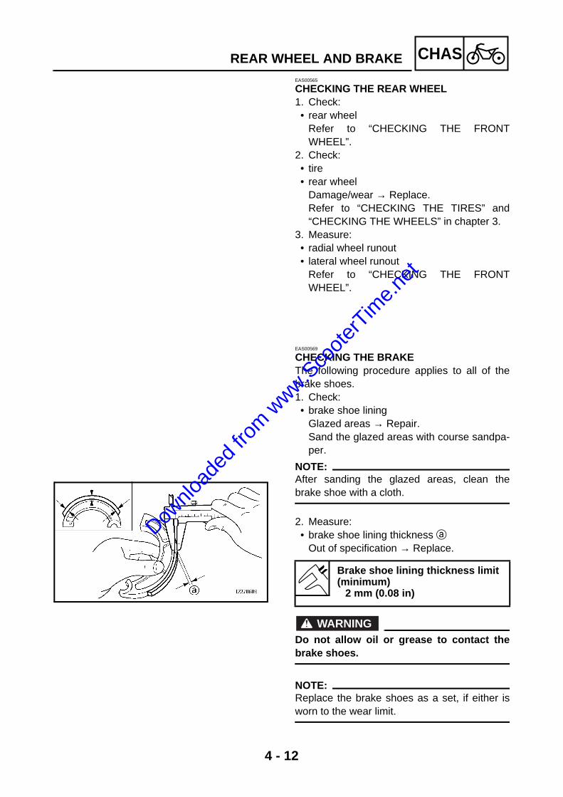
4 - 12
CHASREAR WHEEL AND BRAKEEAS00565
CHECKING THE REAR WHEEL1. Check: • rear wheel
Refer to “CHECKING THE FRONTWHEEL”.
2. Check: • tire • rear wheel
Damage/wear → Replace. Refer to “CHECKING THE TIRES” and“CHECKING THE WHEELS” in chapter 3.
3. Measure: • radial wheel runout • lateral wheel runout
Refer to “CHECKING THE FRONTWHEEL”.
EAS00569
CHECKING THE BRAKEThe following procedure applies to all of thebrake shoes.1. Check: • brake shoe lining
Glazed areas → Repair. Sand the glazed areas with course sandpa-per.
NOTE:@
After sanding the glazed areas, clean thebrake shoe with a cloth.
2. Measure: • brake shoe lining thickness a
Out of specification → Replace.
WARNING@
Do not allow oil or grease to contact thebrake shoes.
NOTE:@
Replace the brake shoes as a set, if either isworn to the wear limit.
Brake shoe lining thickness limit (minimum)
2 mm (0.08 in)
Downlo
aded
from w
ww.Sco
oterT
ime.n
et
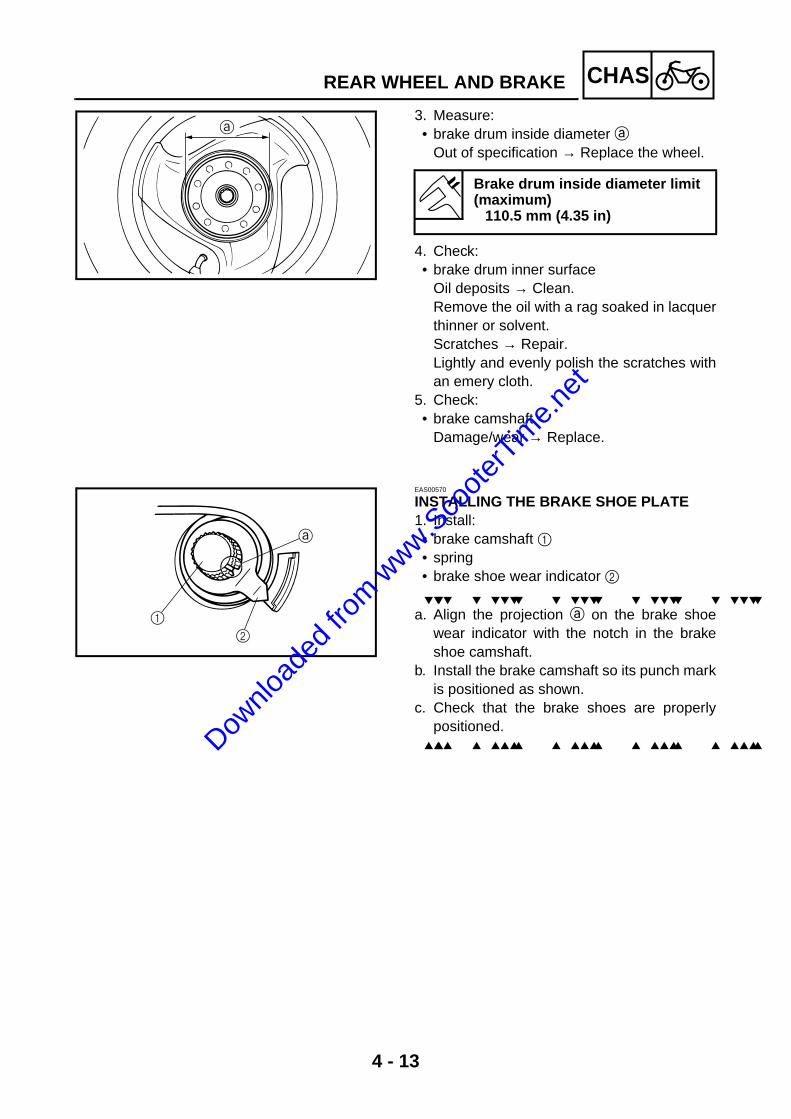
4 - 13
CHASREAR WHEEL AND BRAKE
3. Measure: • brake drum inside diameter a
Out of specification → Replace the wheel.
4. Check: • brake drum inner surface
Oil deposits → Clean. Remove the oil with a rag soaked in lacquerthinner or solvent. Scratches → Repair. Lightly and evenly polish the scratches withan emery cloth.
5. Check: • brake camshaft
Damage/wear → Replace.
Brake drum inside diameter limit (maximum)
110.5 mm (4.35 in)
EAS00570
INSTALLING THE BRAKE SHOE PLATE1. Install: • brake camshaft 1 • spring • brake shoe wear indicator 2
a. Align the projection a on the brake shoewear indicator with the notch in the brakeshoe camshaft.
b. Install the brake camshaft so its punch markis positioned as shown.
c. Check that the brake shoes are properlypositioned.
1
2
Downlo
aded
from w
ww.Sco
oterT
ime.n
et

4 - 14
CHASREAR WHEEL AND BRAKEEAS00573
INSTALLING THE BRAKE SHOES1. Install: • brake camshaft lever 1
NOTE:@
• Align the punch mark a in the brake cam-shaft with the mark b on the brake camshaftlever.
• Lubricate the brake camshaft and pin withlithium soap base grease.
WARNING@
After installing the rear brake camshaft,remove any excess grease.
2. Install: • brake shoes
NOTE:@
Do not to damage the springs during installa-tion.
1
INSTALLING THE REAR WHEEL1. Tighten: • wheel axle nut
CAUTION:@
Do not loosen the wheel axle nut after tight-ening it to the specified torque.
2. Install: • rear brake cable• adjuster
3. Adjust: • brake lever free play
Refer to “ADJUSTING THE REAR BRAKE”in chapter 3.
T R..
105 Nm (10.5 m · kg, 75 ft · lb)Downlo
aded
from w
ww.Sco
oterT
ime.n
et

4 - 15
CHASFRONT SHOCK ABSORBER ASSEMBLIESEAS00647
FRONT SHOCK ABSORBER ASSEMBLIES
Order Job/Part Q’ty Remarks
Removing the front shock absorberassemblies
Remove the parts in the order listed.
The following procedure applies to bothof the front shock absorbers.
Front panel Refer to “FRONT PANEL AND LEGSHIELD” in chapter 3.
Front wheel Refer to “FRONT WHEEL AND BRAKE”.1 Relay arm cover 22 Front fender 13 Relay arm assembly 24 Front shock absorber assembly
(left/right)2
For installation, reverse the removal procedure.
Downlo
aded
from w
ww.Sco
oterT
ime.n
et

4 - 16
CHASFRONT SHOCK ABSORBER ASSEMBLIES
CHECKING THE FRONT SHOCK ABSORBER ASSEMBLIESThe following procedure applies to both frontshock absorber assemblies.1. Check:• front shock absorber rod
Bends/damage → Replace the front shockabsorber assembly.
• front shock absorberOil leaks → Replace the front shockabsorber assembly.
• springDamage/wear → Replace the front shockabsorber assembly.
• boltBends/damage/wear → Replace.
INSTALLING THE RELAY ARM1. Install:• metal spacer 1• oil seal 2 • bushing 3• spacer 4
LS
LS
2
1
2
4
3
New
New
New
Downlo
aded
from w
ww.Sco
oterT
ime.n
et
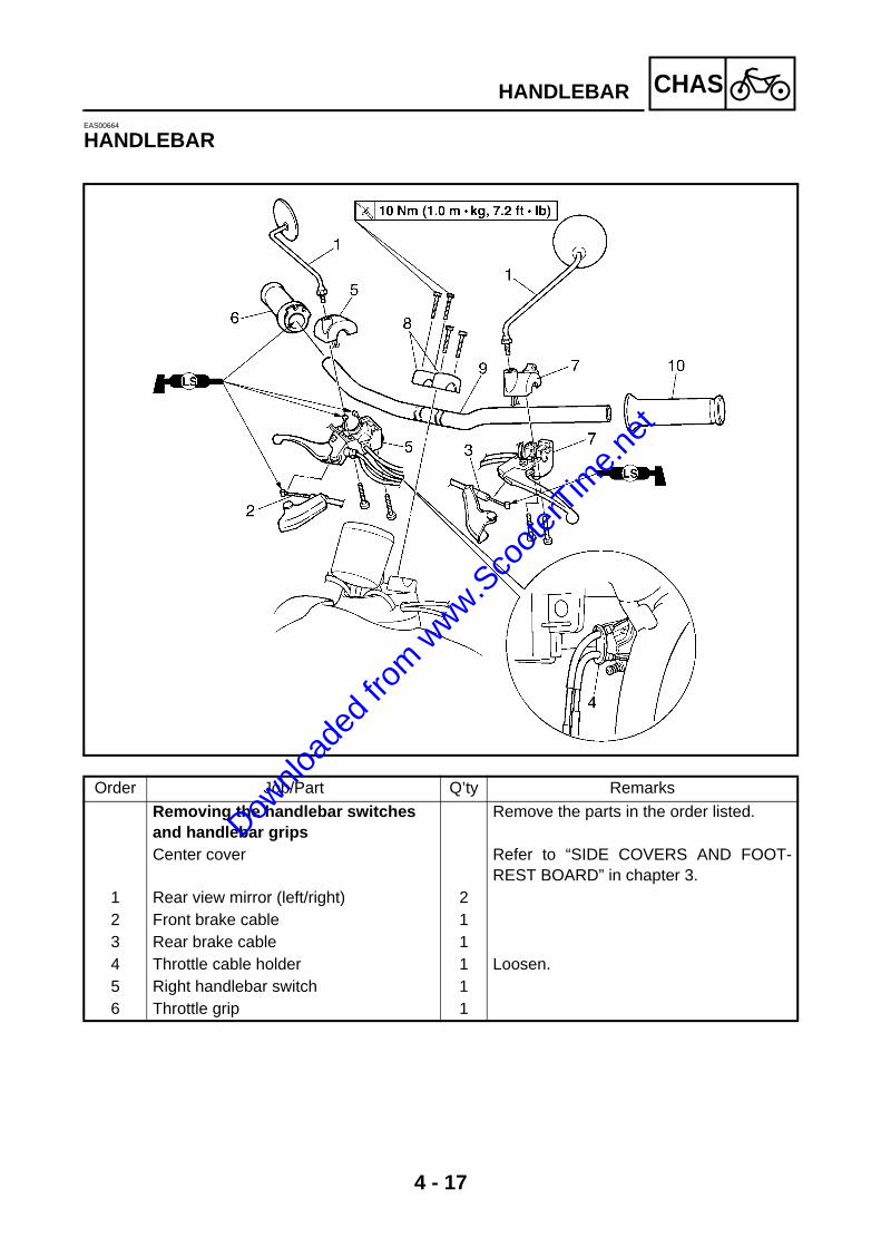
4 - 17
CHASHANDLEBAREAS00664
HANDLEBAR
Order Job/Part Q’ty Remarks
Removing the handlebar switches and handlebar grips
Remove the parts in the order listed.
Center cover Refer to “SIDE COVERS AND FOOT-REST BOARD” in chapter 3.
1 Rear view mirror (left/right) 22 Front brake cable 13 Rear brake cable 14 Throttle cable holder 1 Loosen.5 Right handlebar switch 16 Throttle grip 1
Downlo
aded
from w
ww.Sco
oterT
ime.n
et
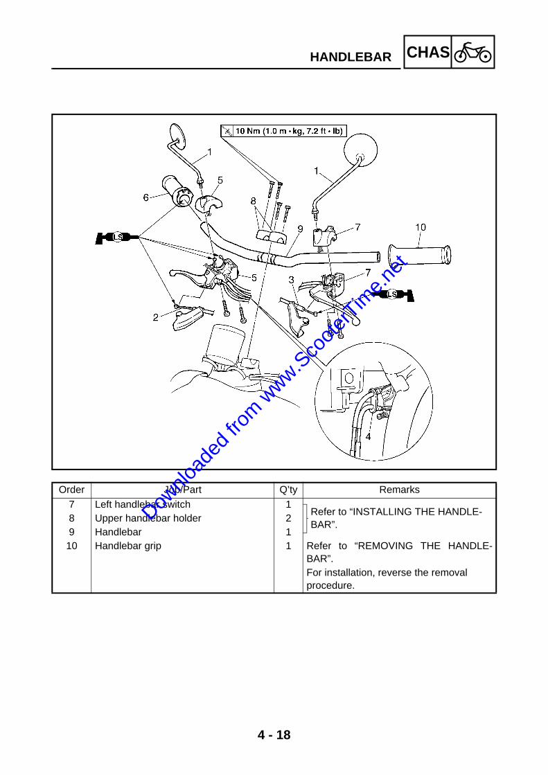
4 - 18
CHASHANDLEBAR
Order Job/Part Q’ty Remarks
7 Left handlebar switch 1Refer to “INSTALLING THE HANDLE-BAR”.
8 Upper handlebar holder 29 Handlebar 1
10 Handlebar grip 1 Refer to “REMOVING THE HANDLE-BAR”.For installation, reverse the removal procedure.
Downlo
aded
from w
ww.Sco
oterT
ime.n
et

4 - 19
CHASHANDLEBAREAS00666
REMOVING THE HANDLEBAR1. Stand the scooter on a level surface.
WARNING@
Securely support the scooter so that thereis no danger of it falling over.
2. Remove: • handlebar grip 1
NOTE:@
Blow compressed air between the handlebarand the handlebar grip, and gradually push thegrip off the handlebar.
1
EAS00668
CHECKING THE HANDLEBAR1. Stand the scooter on a level surface.
WARNING@
Securely support the scooter so that thereis no danger of it falling over.
2. Check: • handlebar 1
Bends/cracks/damage → Replace.
WARNING@
Do not attempt to straighten a bent handle-bar as this may dangerously weaken it.
3. Install: • handlebar grip
a. Apply a thin coat of rubber adhesive ontothe left end of the handlebar.
b. Slide the handlebar grip over the left end ofthe handlebar.
c. Wipe off any excess rubber adhesive with aclean rag.
WARNING@
Do not touch the handlebar grip until therubber adhesive has fully dried.
1
Downlo
aded
from w
ww.Sco
oterT
ime.n
et

4 - 20
CHASHANDLEBAREAS00671
INSTALLING THE HANDLEBAR1. Stand the scooter on a level surface.
WARNING@
Securely support the scooter so that thereis no danger of it falling over.
2. Install: • handlebar 1 • upper handlebar holders 2
CAUTION:@
• First, tighten the bolts on the front side ofthe handlebar holder, and then on the rearside.
NOTE:@
• Install the upper handlebar holders with thegrooves a facing inward.
• Align the match marks b on the handlebarwith the upper surface of the lower handlebarholder.
1
2
T R..
10 Nm (1.0 m · kg, 7.2 ft · lb)
3. Install: • left handlebar switch 1
NOTE:@
Align the mating surfaces of the left handlebarswitch with the punch mark a on the handle-bar.
1
Downlo
aded
from w
ww.Sco
oterT
ime.n
et

4 - 21
CHASHANDLEBAR
4. Install: • throttle grip• throttle cable
NOTE:@
Lubricate the inside of the throttle grip with athin coat of lithium soap base grease andinstall it onto the handlebar.
5. Install: • right handlebar switch 1
WARNING@
Make sure the throttle grip operatessmoothly.
NOTE:@
Align the mating surfaces of the right handle-bar switch with the punch mark a on the han-dlebar.
6. Adjust: • throttle cable free play
Refer to “ADJUSTING THE THROTTLECABLE FREE PLAY” in chapter 3.
Throttle cable free play (at the flange of the throttle grip)
1.5 ~ 3.5 mm (0.06 ~ 0.14 in)
1
Downlo
aded
from w
ww.Sco
oterT
ime.n
et

4 - 22
CHASSTEERING HEAD
STEERING HEAD
Order Job/Part Q’ty Remarks
Removing the lower handlebar holder
Remove the parts in the order listed.
Footrest board Refer to “SIDE COVERS AND FOOT-REST BOARD” in chapter 3.
Front panel/leg shield Refer to “FRONT PANEL AND LEGSHIELD” in chapter 3.
Front shock absorber assemblies Refer to “FRONT SHOCK ABSORBERASSEMBLIES”.
Handlebar Refer to “HANDLEBAR”.1 Meter light lead coupler 1 Disconnect.2 Speedometer assembly 13 Speedometer cable 14 Lower handlebar holder cover 15 Rubber cover 16 Lower handlebar holder bracket 1 For installation, reverse the removal
procedure.
Downlo
aded
from w
ww.Sco
oterT
ime.n
et

4 - 23
CHASSTEERING HEAD
Order Job/Part Q’ty Remarks
Removing the fork Remove the parts in the order listed.1 Cover 12 Upper steering stem ring nut 13 Upper race 14 Fork 15 Upper bearing 16 Lower bearing 17 Upper bearing outer race 18 Lower bearing outer race 1
For installation, reverse the removal procedure.
Downlo
aded
from w
ww.Sco
oterT
ime.n
et

4 - 24
CHASSTEERING HEADEAS00680
REMOVING THE FORK1. Stand the scooter on a level surface.
WARNING@
Securely support the scooter so that thereis no danger of it falling over.
2. Remove: • upper steering stem ring nut 1 • upper race 2
NOTE:@
Hold the upper race with the steering nutwrench (45 mm), and then remove the uppersteering stem ring nut with the steering nutwrench.
WARNING@
Securely support the lower bracket so thatthere is no danger of it falling.
Steering nut wrench YU-33975
Steering nut wrench (45 mm)YU-01444
1
2
EAS00681
CHECKING THE STEERING HEAD1. Wash: • bearings • bearing races
Recommended cleaning solvent Kerosene
2. Check: • bearings 1 • bearing races 2
Damage/pitting → Replace.
2 1
Downlo
aded
from w
ww.Sco
oterT
ime.n
et
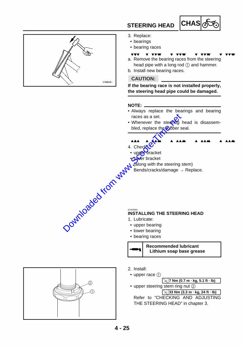
4 - 25
CHASSTEERING HEAD
3. Replace: • bearings • bearing races
a. Remove the bearing races from the steeringhead pipe with a long rod 1 and hammer.
b. Install new bearing races.
CAUTION:@
If the bearing race is not installed properly,the steering head pipe could be damaged.
NOTE:@
• Always replace the bearings and bearingraces as a set.
• Whenever the steering head is disassem-bled, replace the rubber seal.
4. Check: • upper bracket • lower bracket
(along with the steering stem) Bends/cracks/damage → Replace.
EAS00684
INSTALLING THE STEERING HEAD1. Lubricate: • upper bearing • lower bearing • bearing races
Recommended lubricant Lithium soap base grease
2. Install: • upper race 1
• upper steering stem ring nut 2
Refer to “CHECKING AND ADJUSTINGTHE STEERING HEAD” in chapter 3.
2
1
T R..
7 Nm (0.7 m · kg, 5.1 ft · lb)
T R..
33 Nm (3.3 m · kg, 24 ft · lb)
Downlo
aded
from w
ww.Sco
oterT
ime.n
et
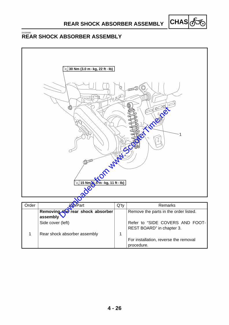
4 - 26
CHASREAR SHOCK ABSORBER ASSEMBLYEAS00685
REAR SHOCK ABSORBER ASSEMBLY
T R..
30 Nm (3.0 m • kg, 22 ft • Ib)
T R..
15 Nm (1.5 m • kg, 11 ft • Ib)
1
Order Job/Part Q’ty Remarks
Removing the rear shock absorberassembly
Remove the parts in the order listed.
Side cover (left) Refer to “SIDE COVERS AND FOOT-REST BOARD” in chapter 3.
1 Rear shock absorber assembly 1For installation, reverse the removal procedure.
Downlo
aded
from w
ww.Sco
oterT
ime.n
et
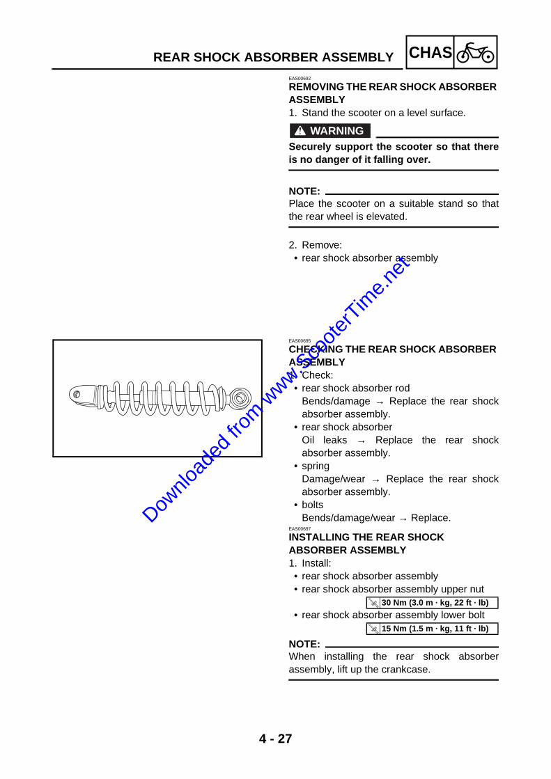
4 - 27
CHASREAR SHOCK ABSORBER ASSEMBLYEAS00692
REMOVING THE REAR SHOCK ABSORBER ASSEMBLY1. Stand the scooter on a level surface.
WARNING@
Securely support the scooter so that thereis no danger of it falling over.
NOTE:@
Place the scooter on a suitable stand so thatthe rear wheel is elevated.
2. Remove: • rear shock absorber assembly
EAS00695
CHECKING THE REAR SHOCK ABSORBER ASSEMBLY1. Check: • rear shock absorber rod
Bends/damage → Replace the rear shockabsorber assembly.
• rear shock absorber Oil leaks → Replace the rear shockabsorber assembly.
• spring Damage/wear → Replace the rear shockabsorber assembly.
• bolts Bends/damage/wear → Replace.
EAS00697
INSTALLING THE REAR SHOCK ABSORBER ASSEMBLY1. Install: • rear shock absorber assembly• rear shock absorber assembly upper nut
• rear shock absorber assembly lower bolt
NOTE:@
When installing the rear shock absorberassembly, lift up the crankcase.
T R..
30 Nm (3.0 m · kg, 22 ft · lb)
T R..
15 Nm (1.5 m · kg, 11 ft · lb)
Downlo
aded
from w
ww.Sco
oterT
ime.n
et

Downlo
aded
from w
ww.Sco
oterT
ime.n
et

ENG
5Downlo
aded
from w
ww.Sco
oterT
ime.n
et

ENG
CHAPTER 5ENGINE
ENGINE REMOVAL ........................................................................................5-1INSTALLING THE ENGINE.......................................................................5-3
CYLINDER HEAD, CYLINDER AND PISTON ...............................................5-4REMOVING THE CYLINDER AND PISTON.............................................5-6CHECKING THE CYLINDER HEAD .........................................................5-6CHECKING THE CYLINDER AND PISTON .............................................5-7CHECKING THE PISTON RINGS.............................................................5-8CHECKING THE PISTON PIN ..................................................................5-9INSTALLING THE PISTON AND CYLINDER .........................................5-11
KICKSTARTER .............................................................................................5-13SHEAVES COVER .................................................................................5-13CHECKING THE KICKSTARTER ...........................................................5-15INSTALLING THE KICKSTARTER .........................................................5-15
BELT DRIVE .................................................................................................5-16REMOVING THE SECONDARY PULLEY AND V-BELT ........................5-19REMOVING THE PRIMARY SHEAVE....................................................5-20DISASSEMBLING THE SECONDARY PULLEY ....................................5-20CHECKING THE CLUTCH SHOES ........................................................5-20CHECKING THE SECONDARY PULLEY...............................................5-21CHECKING THE V-BELT........................................................................5-22CHECKING THE PRIMARY PULLEY WEIGHTS ...................................5-22ASSEMBLING THE SECONDARY PULLEY ..........................................5-23INSTALLING THE PRIMARY PULLEY ...................................................5-24INSTALLING THE BELT DRIVE .............................................................5-25
STARTER CLUTCH AND STARTER MOTOR ............................................5-27CHECKING THE STARTER CLUTCH ....................................................5-28INSTALLING THE STARTER CLUTCH ..................................................5-28
TRANSMISSION ...........................................................................................5-30CHECKING THE TRANSMISSION .........................................................5-32
GENERATOR AND AUTOLUBE PUMP .......................................................5-33STATOR COIL ASSEMBLY ....................................................................5-33AUTOLUBE PUMP..................................................................................5-34REMOVING THE GENERATOR .............................................................5-35CHECKING THE AUTOLUBE PUMP......................................................5-35INSTALLING THE AUTOLUBE PUMP....................................................5-35INSTALLING THE GENERATOR............................................................5-36
Downlo
aded
from w
ww.Sco
oterT
ime.n
et

ENG
CRANKCASE ................................................................................................5-37DISASSEMBLING THE CRANKCASE....................................................5-39CHECKING THE CRANKCASE ..............................................................5-39CHECKING THE BEARINGS AND OIL SEALS......................................5-40CHECKING THE REED VALVE..............................................................5-40ASSEMBLING THE CRANKCASE..........................................................5-41
CRANKSHAFT ..............................................................................................5-42REMOVING THE CRANKSHAFT ASSEMBLY .......................................5-43CHECKING THE CRANKSHAFT ............................................................5-43INSTALLING THE CRANKSHAFT ..........................................................5-44
Downlo
aded
from w
ww.Sco
oterT
ime.n
et

5 - 1
ENG
ENGINEENGINE REMOVAL
5
6 7
1316
8
2
1112
10
15
14
9
4 3
T R..
84 Nm (8.4 m • kg, 61 ft • Ib)
T R..
15 Nm (1.5 m • kg, 11 ft • Ib)
T R..
28 Nm (2.8 m • kg, 20 ft • Ib)
T R..
11 Nm (1.1 m • kg, 8.0 ft • Ib)
T R..
13 Nm (1.3 m • kg, 9.4 ft • Ib)
1
New
Order Job/Part Q’ty Remarks
Removing the engine Remove the parts in the order listed.Center cover, side cover (left/right) andfootrest board
Refer to “SIDE COVERS AND FOOT-REST BOARD” in chapter 3.
Carburetor Refer to “CARBURETOR” in chapter 6.1 Muffler 12 Coupler cover 13 Stator coil coupler 1 Disconnect.4 Starter motor coupler 1 Disconnect.5 Starter relay coupler 1 Disconnect.6 Battery 17 Battery box 18 Oil hose 19 Spark plug cap 1
ENGINE REMOVAL
Downlo
aded
from w
ww.Sco
oterT
ime.n
et

5 - 2
ENGENGINE REMOVAL
5
6 7
1316
8
2
1112
10
15
14
9
4 3
T R..
84 Nm (8.4 m • kg, 61 ft • Ib)
T R..
15 Nm (1.5 m • kg, 11 ft • Ib)
T R..
28 Nm (2.8 m • kg, 20 ft • Ib)
T R..
11 Nm (1.1 m • kg, 8.0 ft • Ib)
T R..
13 Nm (1.3 m • kg, 9.4 ft • Ib)
1
New
Order Job/Part Q’ty Remarks
10 Adjusting nut 111 Rear brake cable 112 Pin 113 Kickstarter crank 114 Bolt (rear shock absorber-lower) 115 Engine mounting bolt/nut 1/116 Engine assembly 1
For installation, reverse the removal procedure.
Downlo
aded
from w
ww.Sco
oterT
ime.n
et

5 - 3
ENGENGINE REMOVALEAS00192
INSTALLING THE ENGINE1. Install: • engine mounting bolt/nut 1
• bolt (rear shock absorber-lower) 2
2. Install: • kickstarter crank
• muffler• bolts• exhaust pipe bolts
T R..
84 Nm (8.4 m · kg, 61 ft · lb)
T R..
15 Nm (1.5 m · kg, 11 ft · lb)
T R..
11 Nm (1.1 m · kg, 8.0 ft · lb)
T R..
28 Nm (2.8 m · kg, 20 ft · lb)
T R..
13 Nm (1.3 m · kg, 9.4 ft · lb)
Downlo
aded
from w
ww.Sco
oterT
ime.n
et
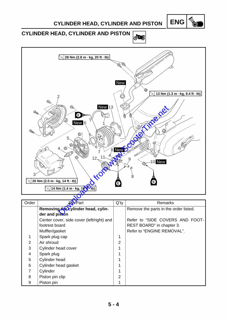
5 - 4
ENGCYLINDER HEAD, CYLINDER AND PISTON
CYLINDER HEAD, CYLINDER AND PISTON
910
8
12 117 84
5
3
6 1
13
2
T R..
14 Nm (1.4 m • kg, 10 ft • Ib)
T R..
20 Nm (2.0 m • kg, 14 ft • Ib)
T R..
13 Nm (1.3 m • kg, 9.4 ft • Ib)
T R..
28 Nm (2.8 m • kg, 20 ft • Ib)
New
New
New
New
New
EE
E
Order Job/Part Q’ty Remarks
Removing the cylinder head, cylin-der and piston
Remove the parts in the order listed.
Center cover, side cover (left/right) andfootrest board
Refer to “SIDE COVERS AND FOOT-REST BOARD” in chapter 3.
Muffler/gasket Refer to “ENGINE REMOVAL”.1 Spark plug cap 12 Air shroud 23 Cylinder head cover 14 Spark plug 15 Cylinder head 16 Cylinder head gasket 17 Cylinder 18 Piston pin clip 29 Piston pin 1
Downlo
aded
from w
ww.Sco
oterT
ime.n
et

5 - 5
ENGCYLINDER HEAD, CYLINDER AND PISTON
910
8
12 117 84
5
3
6 1
13
2
T R..
14 Nm (1.4 m • kg, 10 ft • Ib)
T R..
20 Nm (2.0 m • kg, 14 ft • Ib)
T R..
13 Nm (1.3 m • kg, 9.4 ft • Ib)
T R..
28 Nm (2.8 m • kg, 20 ft • Ib)
New
New
New
New
New
EE
E
Order Job/Part Q’ty Remarks
10 Bearing 111 Piston 112 Piston ring set 113 Cylinder gasket 1
For installation, reverse the removal procedure.
Downlo
aded
from w
ww.Sco
oterT
ime.n
et

5 - 6
ENGCYLINDER HEAD, CYLINDER AND PISTONEAS00253
REMOVING THE CYLINDER AND PISTON1. Remove: • piston pin clip 1 • piston pin 2 • piston 3
CAUTION:@
Do not use a hammer to drive the pistonpin out.
NOTE:@
Before removing the piston pin clip, cover thecrankcase opening with a clean rag to preventthe piston pin clip from falling into the crank-case.
3
1
2
2. Remove: • piston ring
NOTE:@
When removing a piston ring, open the endgap with your fingers and lift the other side ofthe ring over the piston crown.
EAS00227
CHECKING THE CYLINDER HEAD1. Eliminate: • combustion chamber carbon deposits
(with a rounded scraper)
NOTE:@
Do not use a sharp instrument to avoid damag-ing or scratching: • spark plug bore threads
2. Check: • cylinder head
Damage/scratches → Replace.3. Measure: • cylinder head warpage
Out of specification → Resurface the cylin-der head.
Maximum cylinder head warpage 0.05 mm (0.002 in)
Downlo
aded
from w
ww.Sco
oterT
ime.n
et

5 - 7
ENGCYLINDER HEAD, CYLINDER AND PISTON
a. Place a straightedge 1 and a thicknessgauge 2 across the cylinder head.
b. Measure the warpage. c. If the limit is exceeded, resurface the cylin-
der head as follows. d. Place a 400 ~ 600 grit wet sandpaper on
the surface plate and resurface the cylinderhead using a figure-eight sanding pattern.
NOTE:@
To ensure an even surface, rotate the cylinderhead several times.
1
2
EAS00255
CHECKING THE CYLINDER AND PISTON1. Check: • piston wall • cylinder wall
Vertical scratches → Rebore or replace thecylinder, and replace the piston and pistonrings as a set.
2. Measure: • piston-to-cylinder clearance
a. Measure cylinder bore “C” with the cylinderbore gauge.
NOTE:@
Measure cylinder bore “C” by taking side-to-side and front-to-back measurements of thecylinder. Then, find the average of the mea-surements.
Cylinder bore “C” 39.993 ~ 40.012 mm(1.5745 ~ 1.5753 in)
Max. taper “T” 0.05 mm (0.002 in)
Out-of-round “R” 0.05 mm (0.002 in)
“C” = maximum of D 1 ~ D6
“T” = maximum of D 1 or D2 – maximum ofD5 or D6
“R” = maximum of D 1, D3 or D5 – mini-mum of D 2, D4 or D6
Downlo
aded
from w
ww.Sco
oterT
ime.n
et

5 - 8
ENGCYLINDER HEAD, CYLINDER AND PISTON
b. If out of specification, rebore or replace thecylinder, and replace the piston and pistonrings as a set.
c. Measure piston skirt diameter “P” with themicrometer.
a 5 mm (0.20 in) from the bottom edge of the pis-ton
d. If out of specification, replace the piston andpiston rings as a set.
e. Calculate the piston-to-cylinder clearancewith the following formula.
f. If out of specification, rebore or replace thecylinder, and replace the piston and pistonrings as a set.
Piston size “P”
Standard39.952 ~ 39.969 mm (1.5729 ~ 1.5736 in)
Piston-to-cylinder clearance = Cylinder bore “C” – Piston skirt diameter “P”
Piston-to-cylinder clearance0.036 ~ 0.048 mm (0.0014 ~ 0.0019 in) <Limit>: 0.1 mm (0.0039 in)
EAS00263
CHECKING THE PISTON RINGS1. Measure: • piston ring side clearance
Out of specification → Replace the pistonand piston rings as a set.
NOTE:@
Before measuring the piston ring side clear-ance, eliminate any carbon deposits from thepiston ring grooves and piston rings.
Downlo
aded
from w
ww.Sco
oterT
ime.n
et
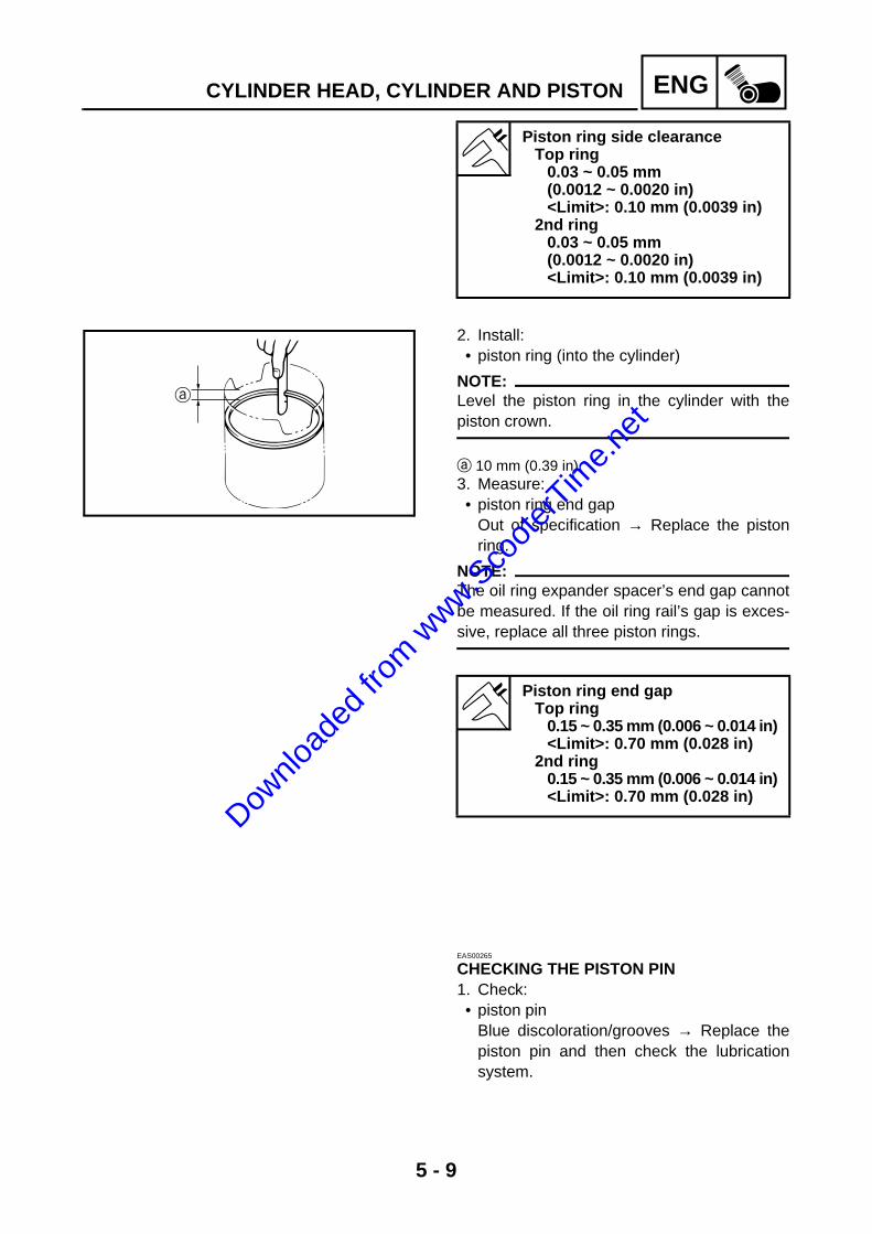
5 - 9
ENGCYLINDER HEAD, CYLINDER AND PISTON
Piston ring side clearance Top ring
0.03 ~ 0.05 mm(0.0012 ~ 0.0020 in) <Limit>: 0.10 mm (0.0039 in)
2nd ring 0.03 ~ 0.05 mm(0.0012 ~ 0.0020 in) <Limit>: 0.10 mm (0.0039 in)
2. Install: • piston ring (into the cylinder)
NOTE:@
Level the piston ring in the cylinder with thepiston crown.
a 10 mm (0.39 in)3. Measure: • piston ring end gap
Out of specification → Replace the pistonring.
NOTE:@
The oil ring expander spacer’s end gap cannotbe measured. If the oil ring rail’s gap is exces-sive, replace all three piston rings.
Piston ring end gap Top ring
0.15 ~ 0.35 mm (0.006 ~ 0.014 in) <Limit>: 0.70 mm (0.028 in)
2nd ring 0.15 ~ 0.35 mm (0.006 ~ 0.014 in) <Limit>: 0.70 mm (0.028 in)
EAS00265
CHECKING THE PISTON PIN1. Check: • piston pin
Blue discoloration/grooves → Replace thepiston pin and then check the lubricationsystem.
Downlo
aded
from w
ww.Sco
oterT
ime.n
et
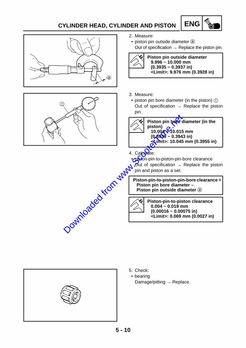
5 - 10
ENGCYLINDER HEAD, CYLINDER AND PISTON
2. Measure: • piston pin outside diameter a
Out of specification → Replace the piston pin.
Piston pin outside diameter 9.996 ~ 10.000 mm (0.3935 ~ 0.3937 in)<Limit>: 9.976 mm (0.3928 in)
3. Measure:• piston pin bore diameter (in the piston) 1
Out of specification → Replace the pistonpin.
Piston pin bore diameter (in the piston)
10.004 ~ 10.015 mm (0.3939 ~ 0.3943 in)<Limit>: 10.045 mm (0.3955 in)
4. Calculate: • piston-pin-to-piston-pin-bore clearance
Out of specification → Replace the pistonpin and piston as a set.
Piston-pin-to-piston-pin-bore clearance = Piston pin bore diameter – Piston pin outside diameter a
Piston-pin-to-piston clearance 0.004 ~ 0.019 mm (0.00016 ~ 0.00075 in) <Limit>: 0.069 mm (0.0027 in)
5. Check: • bearing
Damage/pitting → Replace.
Downlo
aded
from w
ww.Sco
oterT
ime.n
et
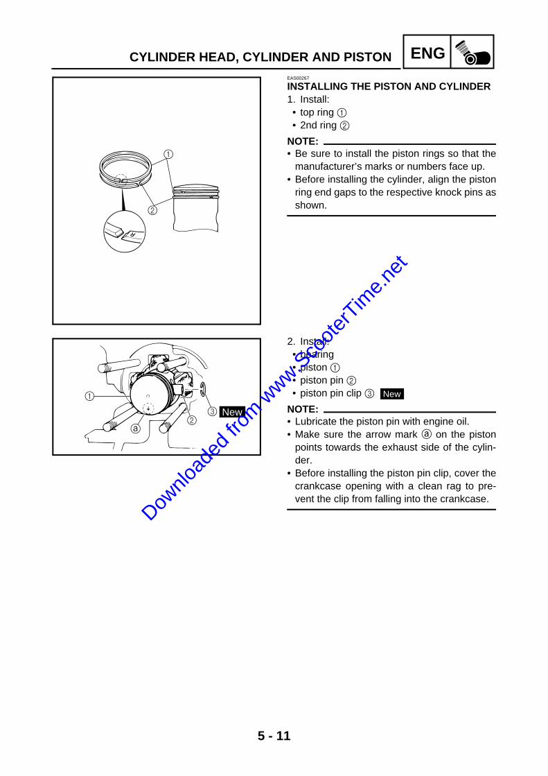
5 - 11
ENGCYLINDER HEAD, CYLINDER AND PISTONEAS00267
INSTALLING THE PISTON AND CYLINDER1. Install: • top ring 1 • 2nd ring 2
NOTE:@
• Be sure to install the piston rings so that themanufacturer’s marks or numbers face up.
• Before installing the cylinder, align the pistonring end gaps to the respective knock pins asshown.
1
2
2. Install: • bearing• piston 1 • piston pin 2 • piston pin clip 3
NOTE:@
• Lubricate the piston pin with engine oil.• Make sure the arrow mark a on the piston
points towards the exhaust side of the cylin-der.
• Before installing the piston pin clip, cover thecrankcase opening with a clean rag to pre-vent the clip from falling into the crankcase.
1
23 New
New
Downlo
aded
from w
ww.Sco
oterT
ime.n
et

5 - 12
ENG
3. Install: • cylinder gasket 1
4. Lubricate: • piston • piston rings • cylinder
(with the recommended lubricant)
5. Install: • cylinder 2
NOTE:@
While compressing the piston rings with onehand, install the cylinder with the other hand.
• cylinder head gasket• cylinder head
Recommended lubricant Yamalube 2-cycle oil or 2-strokeengine oil
T R..
Cylinder nut 14 Nm (1.4 m · kg, 10 ft · lb)
1
2
New
New
CYLINDER HEAD, CYLINDER AND PISTON
Downlo
aded
from w
ww.Sco
oterT
ime.n
et
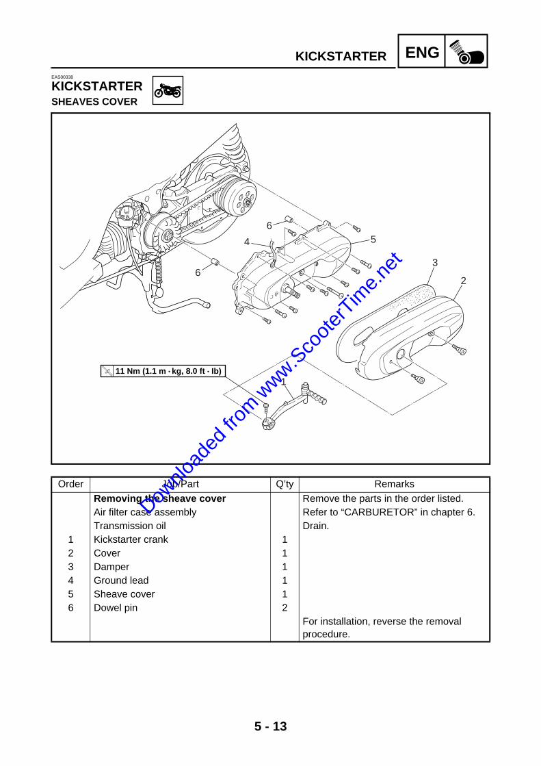
5 - 13
ENGKICKSTARTEREAS00338
KICKSTARTERSHEAVES COVER
6
4
65
3
2
1
T R..
11 Nm (1.1 m • kg, 8.0 ft • Ib)
Order Job/Part Q’ty Remarks
Removing the sheave cover Remove the parts in the order listed.Air filter case assembly Refer to “CARBURETOR” in chapter 6.Transmission oil Drain.
1 Kickstarter crank 12 Cover 13 Damper 14 Ground lead 15 Sheave cover 16 Dowel pin 2
For installation, reverse the removal procedure.
Downlo
aded
from w
ww.Sco
oterT
ime.n
et

5 - 14
ENGKICKSTARTER
5
6
2
1
7
34
LS
New
Order Job/Part Q’ty Remarks
Disassembling the kickstarter shaft Remove the parts in the order listed.1 Kickstarter pinion gear 12 Kickstarter pinion gear clip 13 Circlip 14 Washer 15 Kickstarter shaft 16 Kickstarter spring 17 Spacer 1
For assembly, reverse the disassembly procedure.
Downlo
aded
from w
ww.Sco
oterT
ime.n
et

5 - 15
ENGKICKSTARTEREAS00339
CHECKING THE KICKSTARTER1. Check: • kickstarter shaft• kickstarter pinion gear
Damage/wear → Replace.2. Check: • kickstarter spring
Damage/wear → Replace.
3. Measure: • kickstarter pinion gear clip force
(with the spring gauge) Out of specification → Replace the kick-starter pinion gear clip.
Kickstarter pinion gear clip force 0.15 ~ 0.25 kg (0.34 ~ 0.56 lb)
EAS00340
INSTALLING THE KICKSTARTER1. Install: • kickstarter shaft 1 • kickstarter spring 2• spacer• washer• circlip
NOTE:@
• Install the wire 3 onto the kickstarter spring.• Install the kickstarter spring straight end on
the kickstarter shaft notch 4 and hook thespring hooked end on the projection 5 asshown.
2
1
34
5
Downlo
aded
from w
ww.Sco
oterT
ime.n
et

5 - 16
ENGBELT DRIVEEAS00316
BELT DRIVE
New16
4
3
12
56
78
910
11
1215
14
13
T R..
30 Nm (3.0 m • kg, 22 ft • Ib)
T R..
40 Nm (4.0 m • kg, 29 ft • Ib)
Order Job/Part Q’ty Remarks
Removing the V-belt, primary and secondary pulley
Remove the parts in the order listed.
Sheaves cover Refer to “KICK STARTER”.Air shroud/fan Refer to “GENERATOR AND AUTOL-
UBE PUMP”.1 O-ring 12 Clutch housing 13 Secondary pulley 14 V-belt 15 Conical spring washer 16 Kickstarter one-way clutch 17 Claw washer 18 Primary fixed sheave 19 Washer 1
10 Spacer 1
Downlo
aded
from w
ww.Sco
oterT
ime.n
et

5 - 17
ENGBELT DRIVE
New16
4
3
12
56
78
910
11
1215
14
13
T R..
30 Nm (3.0 m • kg, 22 ft • Ib)
T R..
40 Nm (4.0 m • kg, 29 ft • Ib)
Order Job/Part Q’ty Remarks
11 Collar 112 Primary sliding sheave 113 Slider 114 Cam 115 Primary pulley weight 616 Gasket 1
For installation, reverse the removal procedure.
Downlo
aded
from w
ww.Sco
oterT
ime.n
et

5 - 18
ENGBELT DRIVE
LS
LS
LS
New3
2
1
3 New
8 New
7
9
6
0
9
5
4
T R..
50 Nm (5.0 m • kg, 36 ft • Ib)
Order Job/Part Q’ty Remarks
Disassembling the secondary pulley Remove the parts in the order listed.1 Clutch carrier nut 12 Clutch carrier 13 Clutch spring 24 Spring 15 Spring seat 16 Pin 27 Secondary sliding sheave 18 O-ring 29 Oil seal 10 Secondary fixed sheave 1
For assembly, reverse the disassembly procedure.
Downlo
aded
from w
ww.Sco
oterT
ime.n
et

5 - 19
ENGBELT DRIVEEAS00318
REMOVING THE SECONDARY PULLEY AND V-BELT1. Remove: • air shroud• fan
Refer to “GENERATOR AND AUTOLUBEPUMP”.
2. Remove: • clutch housing nut 1 • clutch housing 2
NOTE:@
While holding the clutch housing with thesheave holder 3, loosen the clutch housingnut.
Sheave holder YU-01701
3
2
1
3. Remove: • secondary pulley 1 • V-belt 2
NOTE:@
Pull the secondary sliding sheave out asshown, remove the V-belt from the primarypulley, and then remove the secondary pulley1 along with the V-belt 2.
2
1
4. Loosen: • clutch carrier nut 1
CAUTION:@
Do not remove the clutch carrier nut at thisstage.
NOTE:@
While holding the clutch carrier with the rotorholding tool 2, loosen the clutch carrier nutone full turn with the locknut wrench.
Rotor holding toolYU-01235
Locknut wrench90890-01348
2
1 Downlo
aded
from w
ww.Sco
oterT
ime.n
et

5 - 20
ENGBELT DRIVEEAS00317
REMOVING THE PRIMARY SHEAVE1. Remove: • primary sheave nut 1 • conical spring washer• kickstarter one-way clutch• claw washer• primary fixed sheave 2
NOTE:@
While holding the generator rotor with the rotorholding tool 3, loosen the primary sheave nut.
Rotor holding toolYU-01235
2
1 3
EAS00319
DISASSEMBLING THE SECONDARY PULLEY1. Remove: • clutch carrier nut 1
NOTE:@
Install the clutch spring holder 2 onto the sec-ondary pulley as shown. Then, compress thespring, and remove the clutch carrier nut 1.
EAS00291
CHECKING THE CLUTCH SHOESThe following procedure applies to all of theclutch shoes.1. Check: • clutch shoe
Damage/wear → Replace the clutch shoesas a set. Glazed areas → Sand with course sandpa-per.
NOTE:@
After sanding the glazed areas, clean theclutch with a cloth.
Clutch spring holder YS-28891
2
1
Downlo
aded
from w
ww.Sco
oterT
ime.n
et

5 - 21
ENGBELT DRIVE
2. Measure: • clutch shoe thickness
Out of specification → Replace the clutchshoes as a set.
Clutch shoe thickness 4.0 mm (0.157 in) <Limit>: 1.0 mm (0.039 in)
3. Check:• clutch housing inside diameter a
Out of specification → Replace the clutchhousing.
Clutch housing inside diameter105.0 mm (4.13 in) <Limit>: 105.5 mm (4.15 in)
EAS00322
CHECKING THE SECONDARY PULLEY1. Check: • secondary fixed sheave • secondary sliding sheave
Cracks/damage/wear → Replace the sec-ondary fixed and sliding sheaves as a set.
2. Check: • guide pin groove 1
Damage/wear → Replace the secondaryfixed and sliding sheaves as a set.
3. Check: • guide pin 2
Damage/wear → Replace the secondaryfixed and sliding sheaves as a set.
2
1
4. Check:• spring free length
Out of specification → Replace the spring
Spring free length95.4 mm (3.76 in) <Limit>: 90.7 mm (3.57 in)
Downlo
aded
from w
ww.Sco
oterT
ime.n
et

5 - 22
ENGBELT DRIVEEAS00320
CHECKING THE V-BELT1. Check: • V-belt 1
Cracks/damage/wear → Replace. Grease/oil → Check the primary and sec-ondary pulleys.
2. Measure: • V-belt width a
Out of specification → Replace.
V-belt width 16.6 mm (0.65 in) <Limit>: 15.0 mm (0.59 in)
1
EAS00321
CHECKING THE PRIMARY PULLEY WEIGHTSThe following procedure applies to all of theprimary pulley weights.1. Check: • primary pulley weight
Cracks/damage/wear → Replace.
2. Measure: • primary pulley weight outside diameter a
Out of specification → Replace.
Primary pulley weight outside diameter
15.0 mm (0.59 in) <Limit>: 14.5 mm (0.57 in)
Downlo
aded
from w
ww.Sco
oterT
ime.n
et

5 - 23
ENGBELT DRIVEEAS00324
ASSEMBLING THE SECONDARY PULLEY1. Lubricate: • secondary fixed sheave’s inner surface 1 • secondary sliding sheave’s inner surface 2 • oil seals
(with the recommended lubricant)
2. Install: • secondary sliding sheave 1
NOTE:@
Install the secondary sliding sheave onto thesecondary fixed sheave 2 with the oil sealguide 3.
Recommended lubricant Lithium soap base grease
Oil seal guide YM-01409
LS
LS
1
2
21
3
3. Install: • guide pin 11
4. Lubricate: • guide pin groove 2 • O-ring 3
(with the recommended lubricant)
Recommended lubricant Lithium soap base grease
2LS
3
New
Downlo
aded
from w
ww.Sco
oterT
ime.n
et

5 - 24
ENGBELT DRIVE
5. Install: • secondary fixed sheave 1 • secondary sliding sheave 2 • spring • clutch carrier 3
NOTE:@
Attach the clutch spring holder 4 onto the sec-ondary pulley as shown. Then, compress thespring, and tighten the clutch carrier nut 5.
Clutch spring holder YS-28891
4
3
5
1
2
EAS00323
INSTALLING THE PRIMARY PULLEY1. Clean: • primary fixed sheave • primary sliding sheave • spacer • primary pulley weights
2. Install: • primary pulley weights 1 • slider 2 • cams 3
113
1 3
3
2
3. Install: • primary sliding sheave 4• collar 5• spacer 65
4
6
Downlo
aded
from w
ww.Sco
oterT
ime.n
et

5 - 25
ENGBELT DRIVE
4. Install: • washer 7• primary fixed sheave 8• claw washer 9• kickstarter one-way clutch 0• conical spring washer A• primary sheave nut B
NOTE:• Install the conical spring washer A as shown
in the illustration.• While holding the generator rotor with the
rotor holding tool, tighten the primary sheavenut.
Rotor holding toolYU-01235
BA
09
8
7
0 A
T R..
30 Nm (3.0 m · kg, 22 ft · lb)
EAS00325
INSTALLING THE BELT DRIVE1. Install: • clutch carrier nut 1
NOTE:@
While holding the clutch carrier with the rotorholding tool 2, tighten the clutch carrier nutwith the locknut wrench.
Rotor holding toolYU-01235
1
2
T R..
50 Nm (5.0 m · kg, 36 ft · lb)
Downlo
aded
from w
ww.Sco
oterT
ime.n
et

5 - 26
ENGBELT DRIVE
2. Install: • V-belt 1 • secondary pulley 2
CAUTION:@
Do not allow grease to contact the V-belt,secondary pulley or clutch assembly.
NOTE:@
• The V-belt must be installed, with the arrow3 forward.
• Install the V-belt on the primary pulley, theninstall the secondary pulley 2 along with theV-belt 1.
3
2
1
3. Install: • clutch housing 1 • clutch housing nut 2
NOTE:@
Tighten the clutch housing nut while holdingthe clutch housing with the sheave holder 3.
Sheave holder YU-01701
2
3
1
T R..
40 Nm (4.0 m · kg, 29 ft · lb)
4. Position: • V-belt 1
NOTE:@
Position the V-belt on the primary pulley 2(when the pulley is at its widest position) andon the secondary pulley 3 (when the pulley isat its narrowest position), and make sure theV-belt is tight.
31
2
Downlo
aded
from w
ww.Sco
oterT
ime.n
et

5 - 27
ENGSTARTER CLUTCH AND STARTER MOTOR
STARTER CLUTCH AND STARTER MOTOR
M
LS
LS
New
T R..
13 Nm (1.3 m • kg, 9.4 ft • Ib)
T R..
8 Nm (0.8 m • kg, 5.8 ft • Ib)
8
9
23
21
4
5
6
7
Order Job/Part Q’ty Remarks
Removing the starter clutch and starter motor
Remove the parts in the order listed.
Sheaves cover Refer to “KICKSTARTER”.Primary sliding sheave Refer to “BELT DRIVE”
1 Idle gear plate 12 Washer 23 Idle gear 14 Starter clutch assembly 15 Starter wheel gear 16 Bearing 17 Spacer 18 Starter motor coupler 1 Disconnect.9 Starter motor 1
For installation, reverse the removal procedure.
Downlo
aded
from w
ww.Sco
oterT
ime.n
et

5 - 28
ENGSTARTER CLUTCH AND STARTER MOTOREAS00351
CHECKING THE STARTER CLUTCH1. Check: • starter clutch rollers 1• starter clutch spring caps 2• starter clutch springs 3
Damage/wear → Replace.1
2
3
2. Check: • starter wheel gear 1
Burrs/chips/roughness/wear → Replace thedefective part(s).
3. Check: • starter wheel gear contacting surface
Damage/pitting/wear → Replace the starterwheel gear.
1
4. Check: • starter clutch operation
a. Install the starter wheel gear onto thestarter clutch and hold the starter clutch.
b. When turning the starter wheel gear clock-wise È, the starter clutch and the starterwheel gear should engage, otherwise thestarter clutch is faulty and must bereplaced.
c. When turning the starter wheel gear coun-terclockwise É, it should turn freely, other-wise the starter clutch is faulty and must bereplaced.
EAS00355
INSTALLING THE STARTER CLUTCH1. Install: • starter clutch springs 1• starter clutch spring caps 2• starter clutch rollers 3
1 2 3
3
2
1
Downlo
aded
from w
ww.Sco
oterT
ime.n
et

5 - 29
ENGSTARTER CLUTCH AND STARTER MOTOR
2. Install:• starter wheel gear 1• starter clutch assembly 2
NOTE:@
Install the starter clutch assembly 1 whileturning the starter wheel gear 2 clockwise.
2
1
Downlo
aded
from w
ww.Sco
oterT
ime.n
et

5 - 30
ENGTRANSMISSIONEAS00419
TRANSMISSION
8
6 54
7
11
1
2
3
3
9
New
New
New
G
G
LS
LTLT
New
T R..
9 Nm (0.9 m • kg, 6.5 ft • Ib)
T R..
18 Nm (1.8 m • kg, 13 ft • Ib)
10
Order Job/Part Q’ty Remarks
Removing the transmission Remove the parts in the order listed.Transmission oil Drain.Rear wheel Refer to “REAR WHEEL AND BRAKE” in
chapter 4.Secondary pulley Refer to “BELT DRIVE”.
1 Transmission cover 12 Gasket 13 Dowel pin 24 Washer 15 Conical spring washer 16 Main axle 17 Drive axle 18 Secondary drive gear 1
Downlo
aded
from w
ww.Sco
oterT
ime.n
et
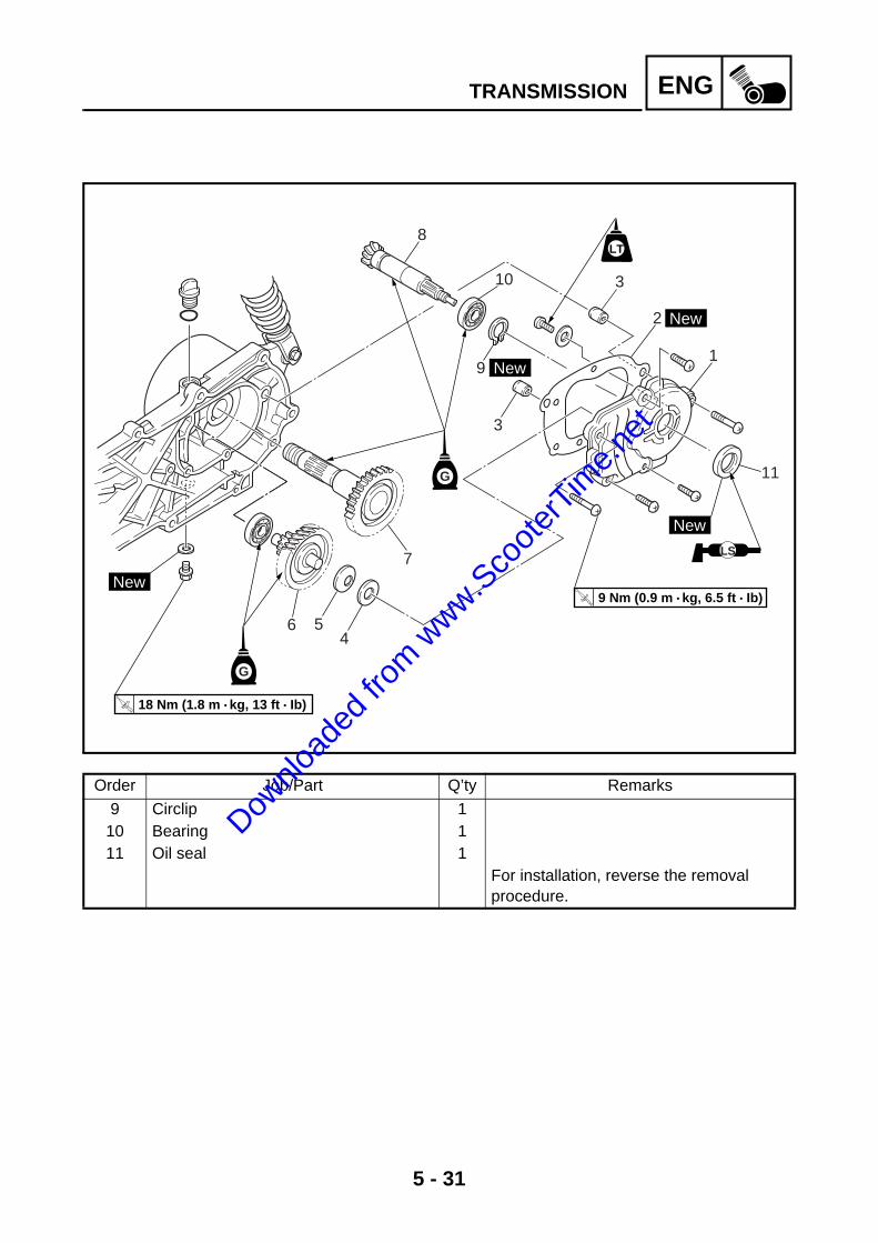
5 - 31
ENGTRANSMISSION
8
6 54
7
11
1
2
3
3
9
New
New
New
G
G
LS
LTLT
New
T R..
9 Nm (0.9 m • kg, 6.5 ft • Ib)
T R..
18 Nm (1.8 m • kg, 13 ft • Ib)
10
Order Job/Part Q’ty Remarks
9 Circlip 110 Bearing 111 Oil seal 1
For installation, reverse the removal procedure.
Downlo
aded
from w
ww.Sco
oterT
ime.n
et

5 - 32
ENGTRANSMISSIONEAS00425
CHECKING THE TRANSMISSION1. Check:• drive axle• main axle• secondary drive gear
Damage/wear → Replace.2. Check:• bearing
Rough movement → Replace.3. Check: • secondary drive gear movement
Rough movement → Replace the defectivepart.
4. Check: • circlips
Bends/damage/looseness → Replace.
Downlo
aded
from w
ww.Sco
oterT
ime.n
et

5 - 33
ENGGENERATOR AND AUTOLUBE PUMP
GENERATOR AND AUTOLUBE PUMPSTATOR COIL ASSEMBLY
3
4
7
1
8
6
2
T R..
38 Nm (3.8 m • kg, 27 ft • Ib)
New
5
Order Job/Part Q’ty Remarks
Removing the stator coil assembly Remove the parts in the order listed.Center cover, side cover (right) andfootrest board
Refer to “SIDE COVERS AND FOOT-REST BOARD” in chapter 3.
1 Coupler cover 12 Air shroud 13 Fan 14 Generator rotor 15 Stator coil assembly coupler 1 Disconnect.6 Stator coil assembly 17 Woodruff key 18 Gasket 1
For installation, reverse the removal procedure.
Downlo
aded
from w
ww.Sco
oterT
ime.n
et

5 - 34
ENGGENERATOR AND AUTOLUBE PUMP
AUTOLUBE PUMP
T R..
6 Nm (0.6 m • kg, 4.3 ft • Ib)
2
1
6
8
9
5
3
43New
NewNew
LS
7
Order Job/Part Q’ty Remarks
Removing the autolube pump Remove the parts in the order listed.Stator coil assembly Refer to “GENERATOR AND AUTOLUBE
PUMP”.1 Spark plug cap 12 Cylinder head cover 13 Circlip 24 Pump drive gear 15 Pin 16 Oil hose 17 Oil delivery hose 18 Autolube pump 19 O-ring 1
For installation, reverse the removal procedure.
Downlo
aded
from w
ww.Sco
oterT
ime.n
et

5 - 35
ENGGENERATOR AND AUTOLUBE PUMPEAS00346
REMOVING THE GENERATOR1. Remove: • generator rotor nut 1 • washer
NOTE:@
While holding the generator rotor 2 with therotor holding tool 3, loosen the generator rotornut.
Rotor holding toolYU-01235
3
1
2
2. Remove: • generator rotor 1
(with the flywheel puller set 2) • woodruff key
Flywheel puller set YU-90105
1
2
CHECKING THE AUTOLUBE PUMP1. Check:• oil hose 1
Obstruction → Blow out with compressedair.
2. Check:• autolube pump 2• pump drive gear 3
Damage → Replace.
INSTALLING THE AUTOLUBE PUMP1. Install:• autolube pump 1• pump drive gear 2
CAUTION:Push the autolube pump in until it contactsthe right crankcase a, and then tighten thepump bolt to the specified torque.
2
1
Downlo
aded
from w
ww.Sco
oterT
ime.n
et

5 - 36
ENGGENERATOR AND AUTOLUBE PUMPEAS00354
INSTALLING THE GENERATOR1. Install: • gasket 1 • woodruff key • generator rotor 2• washer • generator rotor nut
NOTE:@
• Clean the tapered portion of the crankshaftand the generator rotor hub.
• When installing the generator rotor, makesure the woodruff key is properly seated inthe keyway of the crankshaft.
• Do not allow the rotor holding tool to touchthe projection on the generator rotor.
LS1
New
2
2. Tighten: • generator rotor nut 1
NOTE:@
• While holding the generator rotor 2 with therotor holding tool 3, tighten the generatorrotor nut 1.
• Do not allow the rotor holding tool to touchthe projection on the generator rotor.
Rotor holding tool YU-01235
3
1
2
T R..
38 Nm (3.8 m · kg, 27 ft · lb)
Downlo
aded
from w
ww.Sco
oterT
ime.n
et

5 - 37
ENGCRANKCASE
CRANKCASE
T R..
7 Nm (0.7 m • kg, 5.1 ft • Ib)
T R..
9 Nm (0.9 m • kg, 6.5 ft • Ib)
T R..
11 Nm (1.1 m • kg, 8.0 ft • Ib)
LS
LTLT7
7
8
910
11
4
3
2
1
6
5
(6)
New
New
New
Order Job/Part Q’ty Remarks
Separating the crankcase Remove the parts in the order listed.Rear wheel assembly Refer to “REAR WHEEL AND BRAKE” in
chapter 4.Engine assembly Refer to “ENGINE REMOVAL”.Cylinder head, cylinder and piston Refer to “CYLINDER HEAD, CYLINDER
AND PISTON”.Sheaves cover Refer to “KICKSTARTER”.V-belt and secondary pulley Refer to “BELT DRIVE”.Starter clutch assembly and starter motor
Refer to “STARTER CLUCH AND STARTER MOTOR”.
Generator rotor Refer to “GENERATOR AND AUTOL-UBE PUMP”.
Autolube pump Refer to “AUTOLUBE PUMP”.Rear wheel Refer to “REAR WEEL AND BRAKE” in
chapter 4.Transmission Refer to “TRANSMISSION”.
Downlo
aded
from w
ww.Sco
oterT
ime.n
et

5 - 38
ENGCRANKCASE
T R..
7 Nm (0.7 m • kg, 5.1 ft • Ib)
T R..
9 Nm (0.9 m • kg, 6.5 ft • Ib)
T R..
11 Nm (1.1 m • kg, 8.0 ft • Ib)
LS
LTLT7
7
8
910
11
4
3
2
1
6
5
(6)
New
New
New
Order Job/Part Q’ty Remarks
1 Cover 12 Intake manifold 13 Reed valve assembly 14 Valve seat gasket 15 Bearing retainer 16 Right crankcase 1 Refer to “DISASSEMBLING THE
CRANKCASE”.7 Dowel pin 28 Engine mount spacer 19 Circlip 1
10 Bearing 111 Oil seal 1
For installation, reverse the removal procedure.
Downlo
aded
from w
ww.Sco
oterT
ime.n
et
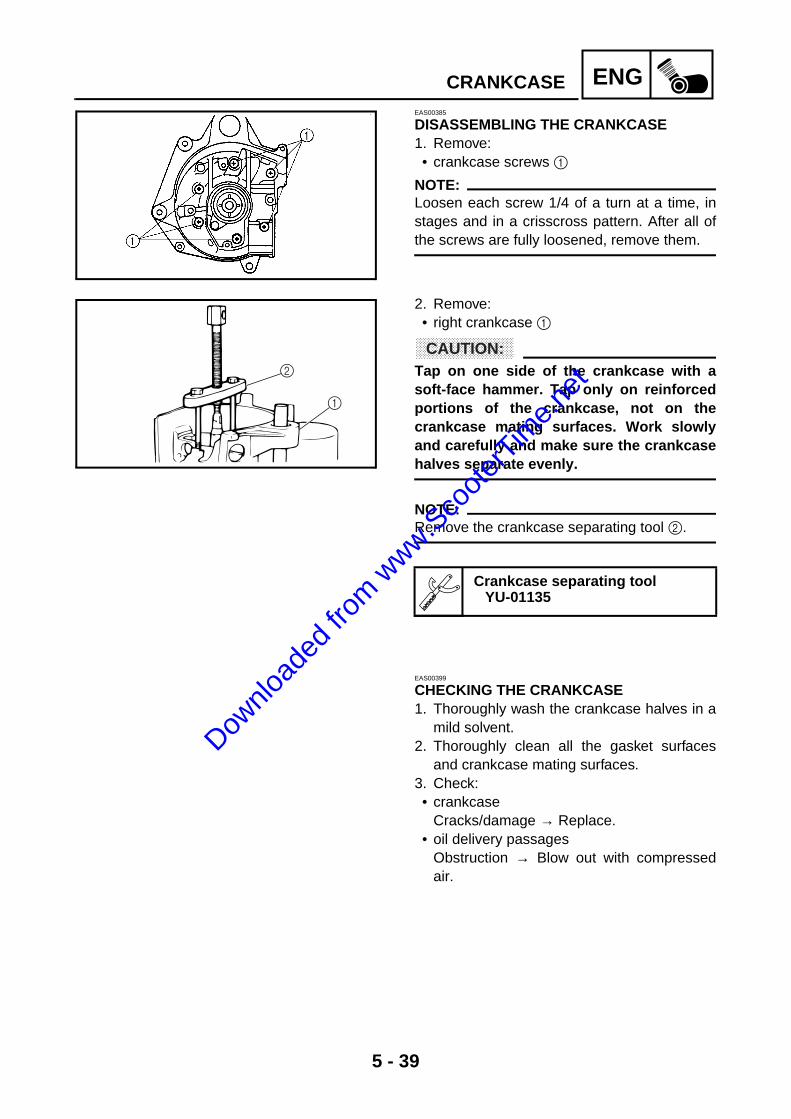
5 - 39
ENGCRANKCASEEAS00385
DISASSEMBLING THE CRANKCASE1. Remove: • crankcase screws 1
NOTE:@
Loosen each screw 1/4 of a turn at a time, instages and in a crisscross pattern. After all ofthe screws are fully loosened, remove them.
2. Remove: • right crankcase 1
CAUTION:@
Tap on one side of the crankcase with asoft-face hammer. Tap only on reinforcedportions of the crankcase, not on thecrankcase mating surfaces. Work slowlyand carefully and make sure the crankcasehalves separate evenly.
NOTE:@
Remove the crankcase separating tool 2.
Crankcase separating tool YU-01135
2
1
EAS00399
CHECKING THE CRANKCASE1. Thoroughly wash the crankcase halves in a
mild solvent. 2. Thoroughly clean all the gasket surfaces
and crankcase mating surfaces.3. Check: • crankcase
Cracks/damage → Replace. • oil delivery passages
Obstruction → Blow out with compressedair.
Downlo
aded
from w
ww.Sco
oterT
ime.n
et

5 - 40
ENGCRANKCASEEAS00401
CHECKING THE BEARINGS AND OIL SEALS1. Check: • bearings
Clean and lubricate the bearings, thenrotate the inner race with your finger. Rough movement → Replace.
2. Check: • oil seals
Damage/wear → Replace.
CHECKING THE REED VALVE1. Measure:• reed valve bending a
Out of specification → Replace.
2. Measure:• valve stopper height b
Out of specification → Adjust stopper/replace valve stopper.
Reed valve bending<Limit>: 0.2 mm (0.008 in)
Valve stopper height7.0 ~ 7.4 mm (0.28 ~ 0.29 in)Dow
nload
ed fro
m www.S
coote
rTim
e.net

5 - 41
ENGEAS00416
ASSEMBLING THE CRANKCASE1. Apply: • sealant
(onto the crankcase mating surfaces)
NOTE:@
Do not allow any sealant to come into contactwith the oil gallery.
2. Install: • dowel pins 1
Quick Gasket ®
ACC-1100-15-01
1
1
3. Install: • left crankcase 1
(onto the right crankcase)Use the crankshaft installing tool.
4. Install: • crankcase screws
NOTE:Tighten each bolt 1/4 of a turn at a time, instages and in a crisscross pattern.
5. Apply: • engine oil
(onto the crankshaft pins bearings and oildelivery holes)
6. Check: • crankshaft and transmission operation
Rough movement → Repair.
Crankshaft installer pot 2YU-90058
Crankshaft installer bolt 3YU-90060
Crankshaft installer adapter(M10) 4
YU-90062
2
4
1
3
T R..
9 Nm (0.9 m · kg, 6.5 ft · lb)
CRANKCASE
Downlo
aded
from w
ww.Sco
oterT
ime.n
et

5 - 42
ENGCRANKSHAFTEAS00381
CRANKSHAFT
3
2
1
2
4
3
E
E
E
New
NewLS
LS
Order Job/Part Q’ty Remarks
Removing the crankshaft Remove the parts in the order listed.Engine assembly Refer to “ENGINE REMOVAL”.Crankcase Separate.
Refer to “CRANKCASE”.1 Crankshaft 12 Bearing 23 Oil seal 14 Crankcase 1 1
For installation, reverse the removal procedure.
Downlo
aded
from w
ww.Sco
oterT
ime.n
et

5 - 43
ENGCRANKSHAFTEAS00388
REMOVING THE CRANKSHAFT ASSEMBLY1. Remove: • crankshaft assembly 1
NOTE:@
• Remove the crankshaft assembly with thecrankcase separating tool 2.
• Make sure the crankcase separating tool iscentered over the crankshaft assembly.
Crankcase separating tool YU-01135
1
2
EAS00394
CHECKING THE CRANKSHAFT 1. Measure: • crankshaft runout 1
Out of specification → Replace the crank-shaft, bearing(s) or both.
NOTE:@
Turn the crankshaft slowly.
2. Measure: • big end side clearance 2
Out of specification → Replace the big endbearing, crankshaft pin, or connecting rod.
3. Measure: • crankshaft width 3
Out of specification → Replace the crank-shaft.
Maximum crankshaft runout 0.03 mm (0.0012 in)
Big end side clearance 0.35 ~ 0.75 mm (0.0138 ~ 0.0295 in)<Limit>: 1 mm (0.0394 in)
Crankshaft width 37.90 ~ 37.95 mm (1.492 ~ 1.494 in)
Downlo
aded
from w
ww.Sco
oterT
ime.n
et

5 - 44
ENGCRANKSHAFT
4. Check: • bearing
Cracks/damage/wear → Replace.
EAS00408
INSTALLING THE CRANKSHAFT1. Install: • crankshaft installing tool
2. Install: • crankshaft assembly 4
(to the left crankcase 5)
CAUTION:@
To avoid scratching the crankshaft and toease the installation procedure, lubricatethe oil seal lips with grease and each bear-ing with engine oil.
NOTE:@
Hold the connecting rod at top dead center(TDC) with one hand while turning the nut ofthe crankshaft installing tool with the other.Turn the crankshaft installing tool until thecrankshaft assembly bottoms against the bear-ing.
Crankshaft installer pot 1YU-90058
Crankshaft installer bolt 2YU-90060
Crankshaft installer adapter (M10) 3
YU-90062
5
4 3 1 2
Downlo
aded
from w
ww.Sco
oterT
ime.n
et

CARB
6Downlo
aded
from w
ww.Sco
oterT
ime.n
et

CARB
CHAPTER 6CARBURETION
CARBURETOR ................................................................................................6-1CHECKING THE CARBURETOR .............................................................6-4ASSEMBLING THE CARBURETOR.........................................................6-5INSTALLING THE CARBURETOR ...........................................................6-6MEASURING AND ADJUSTING THE FLOAT HEIGHT ...........................6-7CHECKING THE AUTOCHOKE ASSEMBLY ...........................................6-7CHECKING THE FUEL COCK OPERATION............................................6-8
Downlo
aded
from w
ww.Sco
oterT
ime.n
et

CARB
Downlo
aded
from w
ww.Sco
oterT
ime.n
et

6 - 1
CARB
CARBURETIONCARBURETOR
2
1
3
4
5
6
7
9
10
8
Order Job/Part Q’ty Remarks
Removing the carburetor Remove the parts in the order listed.Center cover, side cover (left) and foot-rest board
Refer to “SIDE COVERS AND FOOT-REST BOARD” in chapter 3.
1 Air filter case assembly 12 Clip 13 Auto choke coupler 1 Disconnect.4 Oil delivery hose 15 Clamp screw (intake manifold) 1 Loosen.6 Carburetor assembly 17 Fuel hose 18 Vacuum hose 19 Throttle assembly 1
10 O-ring 1For installation, reverse the removal procedure.
CARBURETOR
Downlo
aded
from w
ww.Sco
oterT
ime.n
et

6 - 2
CARBCARBURETOR
1
4
5
3
2
F
E
DC B
A
0
7
9
8
6
Order Job/Part Q’ty Remarks
Disassembling the carburetor Remove the parts in the order listed.
NOTE:@
Before disassembling the carburetor,make sure to note the number of timesthe pilot air screw is turned out from theseated position to its set position.
1 Throttle cables 22 Throttle valve 13 Jet needle kit 14 Mixing chamber cap 15 Throttle stop screw 16 Pilot air screw assembly 17 Auto choke assembly 18 Float chamber 1
Downlo
aded
from w
ww.Sco
oterT
ime.n
et

6 - 3
CARBCARBURETOR
1
4
5
3
2
F
E
DC B
A
0
7
9
8
6
Order Job/Part Q’ty Remarks
9 O-ring 10 Float pivot pin 1A Float 1B Needle valve 1C Main jet 1D Needle jet 1E Pilot jet 1F Carburetor body 1
For assembly, reverse the disassembly procedure.
Downlo
aded
from w
ww.Sco
oterT
ime.n
et
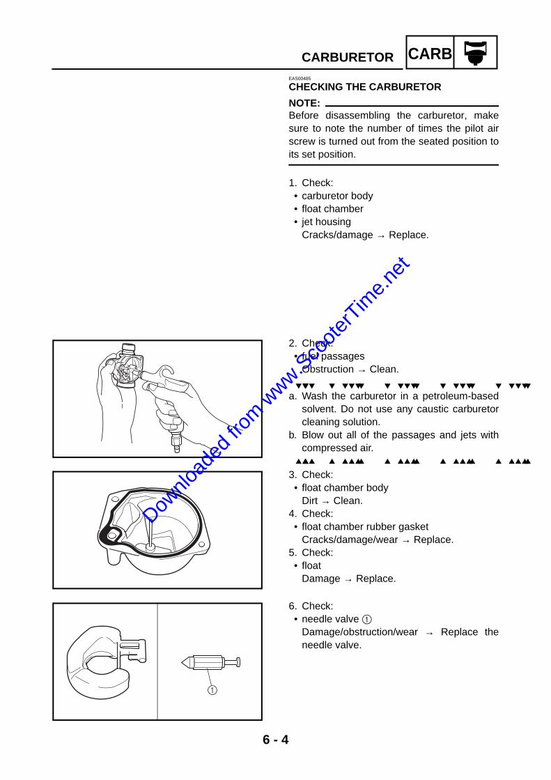
6 - 4
CARBCARBURETOREAS00485
CHECKING THE CARBURETOR
NOTE:Before disassembling the carburetor, makesure to note the number of times the pilot airscrew is turned out from the seated position toits set position.
1. Check: • carburetor body • float chamber • jet housing
Cracks/damage → Replace.
2. Check: • fuel passages
Obstruction → Clean.
a. Wash the carburetor in a petroleum-basedsolvent. Do not use any caustic carburetorcleaning solution.
b. Blow out all of the passages and jets withcompressed air.
3. Check: • float chamber body
Dirt → Clean.4. Check: • float chamber rubber gasket
Cracks/damage/wear → Replace.5. Check: • float
Damage → Replace.
6. Check: • needle valve 1
Damage/obstruction/wear → Replace theneedle valve.
1
Downlo
aded
from w
ww.Sco
oterT
ime.n
et

6 - 5
CARBCARBURETOR
7. Check: • throttle valve 1
Damage/scratches/wear→ Replace.
1
8. Check: • jet needle kit 1 • needle jet 2 • main jet 3 • pilot jet 4 • pilot air screw assembly 5
Bends/damage/wear → Replace. Obstruction → Clean. Blow out the jets with compressed air.
1 2 3 4 5
9. Check: • throttle valve movement
Insert the throttle valve into the carburetorbody and move it up and down. Tightness → Replace the piston valve.
10.Check: • vacuum hose• fuel hose
Cracks/damage/wear → Replace. Obstruction → Clean. Blow out the hoses with compressed air.
EAS00487
ASSEMBLING THE CARBURETOR
NOTE:Before assembling the carburetor, make sureto turn out the pilot air screw the same numberof times, as noted before disassembly, fromthe seated position to the set position.
CAUTION:@
• Before assembling the carburetor, washall of the parts in a petroleum-based sol-vent.
• Always use a new gasket.
1. Install: • needle jet 1 • main jet 2 • pilot jet 3
3 2
1
Downlo
aded
from w
ww.Sco
oterT
ime.n
et

6 - 6
CARBCARBURETOR
2. Install: • needle valve 1 • float 2 • float pivot pin 3 • screw 4
2
3
4
1
3. Install: • float chamber 1 • pilot air screw assembly 2
1
2
4. Install: • starter plunger kit
5. Install: • throttle valve• jet needle holder• jet needle kit
NOTE:Align the groove of the throttle valve with theprojection of the carburetor body.
6. Install: • throttle cable
EAS00492
INSTALLING THE CARBURETOR1. Adjust: • engine idling speed
Refer to “ADJUSTING THE ENGINEIDLING SPEED” in chapter 3.
2. Adjust: • throttle cable free play
Refer to “ADJUSTING THE THROTTLECABLE FREE PLAY” in chapter 3.
Engine idling speed 1,800 r/min
Throttle cable free play (at the flange of the throttle grip)
1.5 ~ 3.5 mm (0.06 ~ 0.14 in)
Downlo
aded
from w
ww.Sco
oterT
ime.n
et
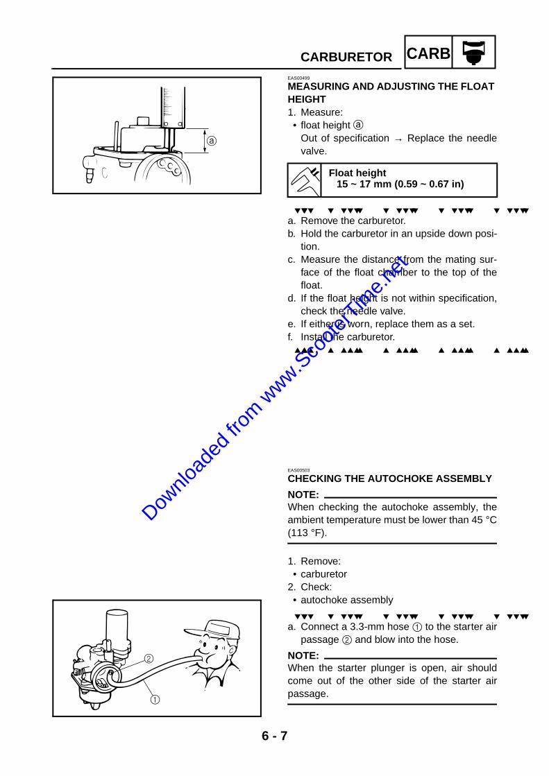
6 - 7
CARBCARBURETOREAS00499
MEASURING AND ADJUSTING THE FLOAT HEIGHT1. Measure: • float height a
Out of specification → Replace the needlevalve.
a. Remove the carburetor. b. Hold the carburetor in an upside down posi-
tion.c. Measure the distance from the mating sur-
face of the float chamber to the top of thefloat.
d. If the float height is not within specification,check the needle valve.
e. If either is worn, replace them as a set. f. Install the carburetor.
Float height15 ~ 17 mm (0.59 ~ 0.67 in)
EAS00503
CHECKING THE AUTOCHOKE ASSEMBLY
NOTE:@
When checking the autochoke assembly, theambient temperature must be lower than 45 °C(113 °F).
1. Remove: • carburetor
2. Check: • autochoke assembly
a. Connect a 3.3-mm hose 1 to the starter airpassage 2 and blow into the hose.
NOTE:@
When the starter plunger is open, air shouldcome out of the other side of the starter airpassage.
2
1
Downlo
aded
from w
ww.Sco
oterT
ime.n
et
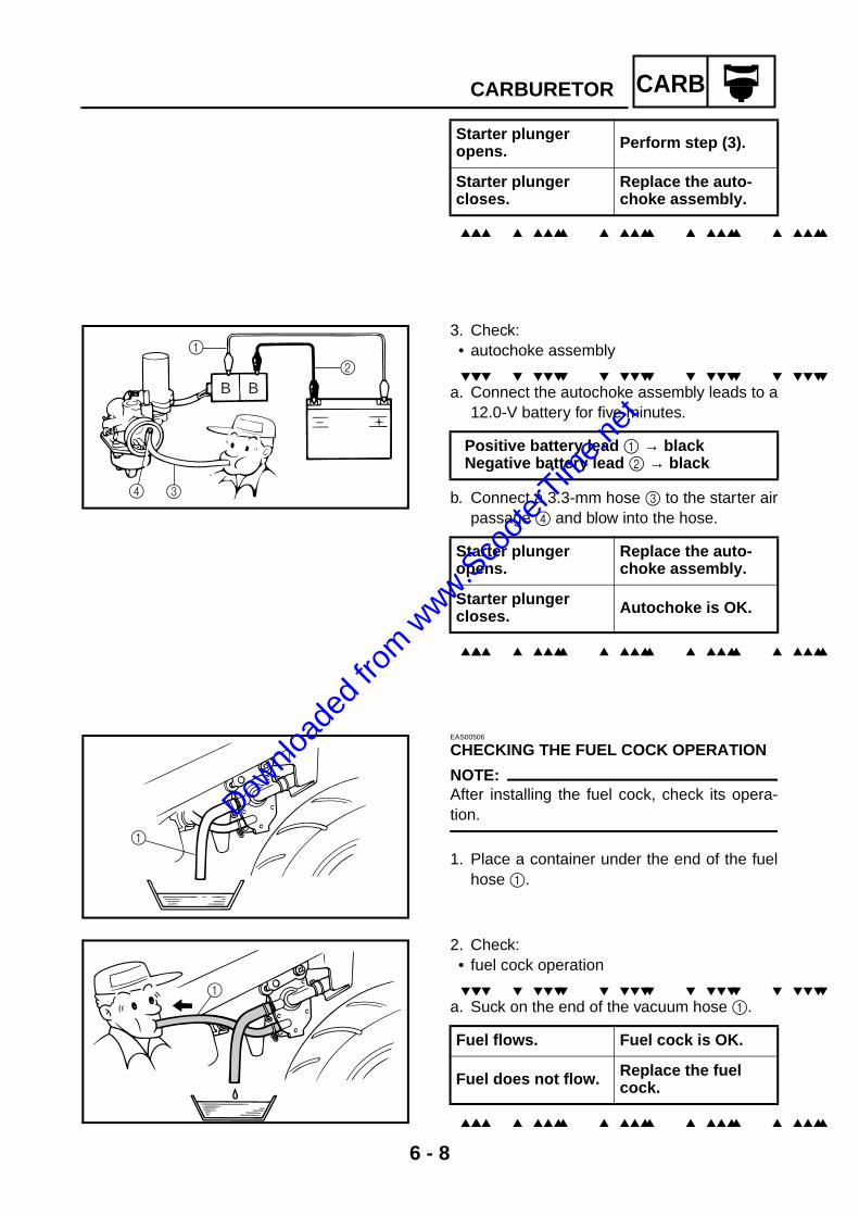
6 - 8
CARBCARBURETOR
Starter plunger opens. Perform step (3).
Starter plunger closes.
Replace the auto-choke assembly.
3. Check: • autochoke assembly
a. Connect the autochoke assembly leads to a12.0-V battery for five minutes.
b. Connect a 3.3-mm hose 3 to the starter airpassage 4 and blow into the hose.
Positive battery lead 1 → black Negative battery lead 2 → black
Starter plunger opens.
Replace the auto-choke assembly.
Starter plunger closes. Autochoke is OK.
4 3
1
2
B B
EAS00506
CHECKING THE FUEL COCK OPERATION
NOTE:@
After installing the fuel cock, check its opera-tion.
1. Place a container under the end of the fuelhose 1.
1
2. Check: • fuel cock operation
a. Suck on the end of the vacuum hose 1.
Fuel flows. Fuel cock is OK.
Fuel does not flow. Replace the fuel cock.
1
Downlo
aded
from w
ww.Sco
oterT
ime.n
et

ELEC
7– +
Downlo
aded
from w
ww.Sco
oterT
ime.n
et

– +ELEC
CHAPTER 7ELECTRICAL
ELECTRICAL COMPONENTS ........................................................................7-1
SWITCHES ......................................................................................................7-2CHECKING SWITCH CONTINUITY .........................................................7-2
CHECKING THE SWITCHES ..........................................................................7-3
CHECKING THE BULBS AND BULB SOCKETS ..........................................7-5TYPES OF BULBS....................................................................................7-5CHECKING THE CONDITION OF THE BULBS .......................................7-6CHECKING THE CONDITION OF THE BULB SOCKETS .......................7-7
IGNITION SYSTEM .........................................................................................7-8CIRCUIT DIAGRAM ..................................................................................7-8TROUBLESHOOTING ..............................................................................7-9
ELECTRIC STARTING SYSTEM ..................................................................7-13CIRCUIT DIAGRAM ................................................................................7-13TROUBLESHOOTING ............................................................................7-14
STARTER MOTOR ........................................................................................7-17CHECKING THE STARTER MOTOR .....................................................7-19ASSEMBLING THE STARTER MOTOR.................................................7-20
CHARGING SYSTEM ....................................................................................7-21CIRCUIT DIAGRAM ................................................................................7-21TROUBLESHOOTING ............................................................................7-22
LIGHTING SYSTEM ......................................................................................7-24CIRCUIT DIAGRAM ................................................................................7-24TROUBLESHOOTING ............................................................................7-25CHECKING THE LIGHTING SYSTEM....................................................7-26
SIGNALING SYSTEM ...................................................................................7-29CIRCUIT DIAGRAM ................................................................................7-29TROUBLESHOOTING ............................................................................7-31CHECKING THE SIGNALING SYSTEM .................................................7-32
AUTO CHOKE SYSTEM ...............................................................................7-39CIRCUIT DIAGRAM ................................................................................7-39TROUBLESHOOTING ............................................................................7-40
Downlo
aded
from w
ww.Sco
oterT
ime.n
et

– +ELEC
Downlo
aded
from w
ww.Sco
oterT
ime.n
et

7 - 1
– +ELECEAS00729
ELECTRICALELECTRICAL COMPONENTS1 Main switch2 Starter relay3 Fuel sender4 Oil level switch5 CDI unit6 Rectifier/regulator7 Main fuse
8 Battery9 Spark plug cap0 Ignition coilAWire harnessB Turn signal relayC Horn
1
C
B
A
0
9
8
7
6
5
4
3
2
ELECTRICAL COMPONENTS
Downlo
aded
from w
ww.Sco
oterT
ime.n
et

7 - 2
– +ELECSWITCHESEAS00730
SWITCHESCHECKING SWITCH CONTINUITYCheck each switch for continuity with thepocket tester. If the continuity reading is incor-rect, check the wiring connections and if nec-essary, replace the switch.
CAUTION:@
Never insert the tester probes into the cou-pler terminal slots 1. Always insert theprobes from the opposite end of the cou-pler, taking care not to loosen or damagethe leads.
NOTE:@
• Before checking for continuity, set the pockettester to “0” and to the “Ω × 1” range.
• When checking for continuity, switch backand forth between the switch positions a fewtimes.
The terminal connections for switches (e.g.,main switch, engine stop switch) are shown inan illustration similar to the one on the left. The switch positions a are shown in the farleft column and the switch lead colors b areshown in the top row in the switch illustration.
NOTE:@
“ ” indicates a continuity of electricitybetween switch terminals (i.e., a closed circuitat the respective switch position).
The example illustration on the left showsthat: There is continuity between red and brownwhen the switch is set to “ON”.
Pocket tester YU-03112
“0”
“Ω×1”
“∞”
1
OFF
ON
RBrGy
RBrGy
Downlo
aded
from w
ww.Sco
oterT
ime.n
et

7 - 3
– +ELECCHECKING THE SWITCHESEAS00731
CHECKING THE SWITCHESCheck each switch for damage or wear, proper connections, and also for continuity between the ter-minals. Refer to “CHECKING SWITCH CONTINUITY”.
Damage/wear → Repair or replace. Improperly connected → Properly connect. Incorrect continuity reading → Replace the switch.
Downlo
aded
from w
ww.Sco
oterT
ime.n
et

7 - 4
– +ELECCHECKING THE SWITCHES
1 Front brake light switch2 Turn signal switch3 Dimmer switch4 Horn switch5 Main switch6 Rear brake light switch7 Start switch8 Engine stop switch9 Main fuse
Downlo
aded
from w
ww.Sco
oterT
ime.n
et
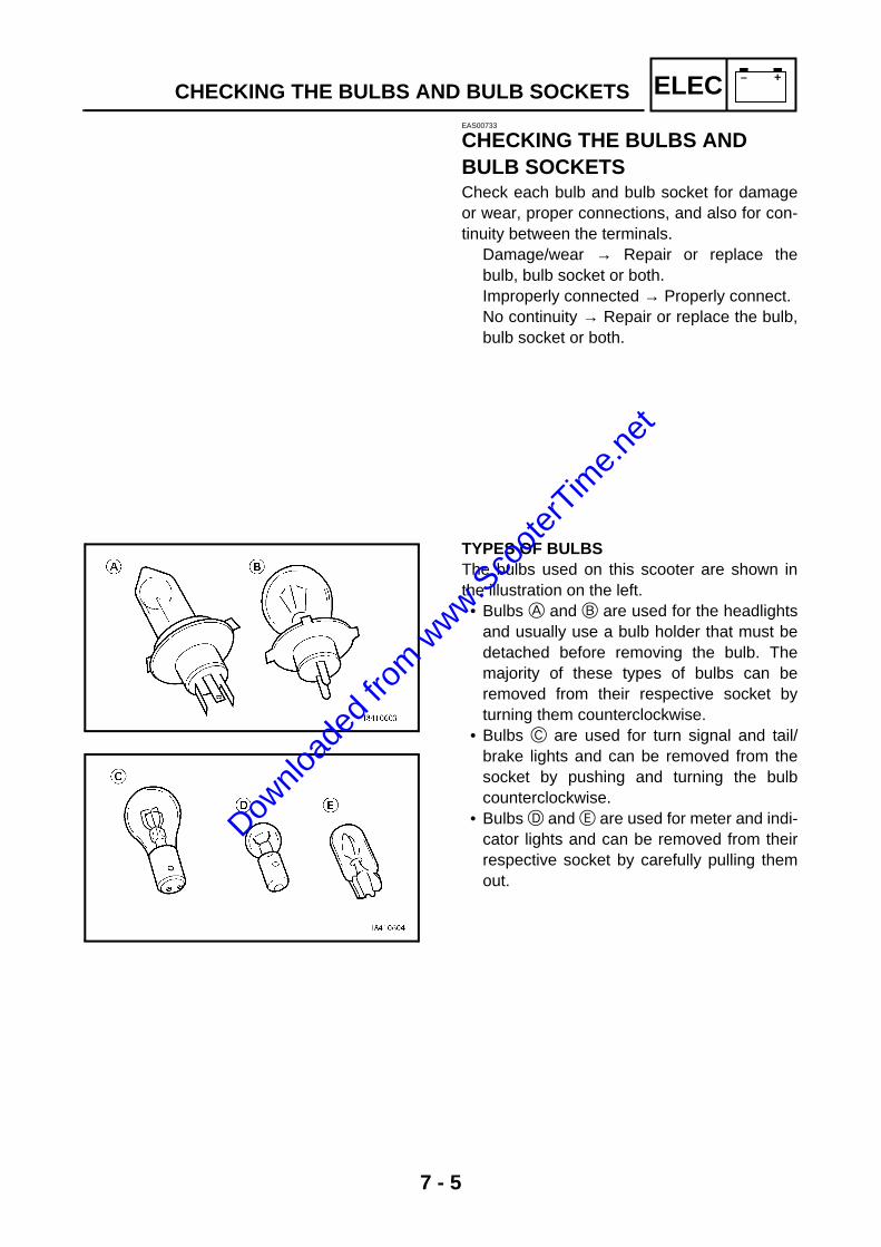
7 - 5
– +ELECCHECKING THE BULBS AND BULB SOCKETSEAS00733
CHECKING THE BULBS AND BULB SOCKETSCheck each bulb and bulb socket for damageor wear, proper connections, and also for con-tinuity between the terminals.
Damage/wear → Repair or replace thebulb, bulb socket or both. Improperly connected → Properly connect. No continuity → Repair or replace the bulb,bulb socket or both.
TYPES OF BULBSThe bulbs used on this scooter are shown inthe illustration on the left. • Bulbs A and B are used for the headlights
and usually use a bulb holder that must bedetached before removing the bulb. Themajority of these types of bulbs can beremoved from their respective socket byturning them counterclockwise.
• Bulbs C are used for turn signal and tail/brake lights and can be removed from thesocket by pushing and turning the bulbcounterclockwise.
• Bulbs D and E are used for meter and indi-cator lights and can be removed from theirrespective socket by carefully pulling themout.
Downlo
aded
from w
ww.Sco
oterT
ime.n
et

7 - 6
– +ELECCHECKING THE BULBS AND BULB SOCKETS
CHECKING THE CONDITION OF THE BULBSThe following procedure applies to all of thebulbs. 1. Remove: • bulb
WARNING@
Since the headlight bulb gets extremelyhot, keep flammable products and yourhands away from the bulb until it hascooled down.
CAUTION:@
• Be sure to hold the socket firmly whenremoving the bulb. Never pull the lead,otherwise it may be pulled out of the ter-minal in the coupler.
• Avoid touching the glass part of the head-light bulb to keep it free from oil, other-wise the transparency of the glass, thelife of the bulb, and the luminous flux willbe adversely affected. If the headlightbulb gets soiled, thoroughly clean it witha cloth moistened with alcohol or lacquerthinner.
2. Check: • bulb (for continuity)
(with the pocket tester) No continuity → Replace.
NOTE:@
Before checking for continuity, set the pockettester to “0” and to the “Ω × 1” range.
a. Connect the positive tester probe to termi-nal 1 and the negative tester probe to ter-minal 2, and check the continuity.
b. Connect the positive tester probe to termi-nal 1 and the negative tester probe to ter-minal 3, and check the continuity.
c. If either of the readings indicate no continu-ity, replace the bulb.
Pocket tester YU-03112Dow
nload
ed fro
m www.S
coote
rTim
e.net

7 - 7
– +ELECCHECKING THE BULBS AND BULB SOCKETS
CHECKING THE CONDITION OF THE BULB SOCKETSThe following procedure applies to all of thebulb sockets. 1. Check: • bulb socket (for continuity)
(with the pocket tester) No continuity → Replace.
NOTE:@
Check each bulb socket for continuity in thesame manner as described in the bulb section;however, note the following.
a. Install a good bulb into the bulb socket. b. Connect the pocket tester probes to the
respective leads of the bulb socket. c. Check the bulb socket for continuity. If any
of the readings indicate no continuity,replace the bulb socket.
Pocket tester YU-03112
Downlo
aded
from w
ww.Sco
oterT
ime.n
et

7 - 8
– +ELECIGNITION SYSTEMEAS00734
IGNITION SYSTEMCIRCUIT DIAGRAM
OF
F
ON
R Br
Gy
Br
GyR
Gy
Br
RR
W
1
23
OO B
CD
BRR
R
B B B
BB
Br
BL/
WL/
Y
Y/R
W Y/R
Y/R
W/L
W/L
RR
R
RG
/Y
R L/W
4
Y/R
WB
R
R
L/W
R
G/Y
R
RR
BR
5
67
8
9
L/Y
L/W
L/W
B
L/Y
L/W
L/W
BL/
WB
L/W
B
Br G
BGB
rB
W/L
B WY
/R WW
/LW
/RY
/R
A
A
(BLA
CK
)
0
B
A B BBY/R
(BLA
CK
)
(RE
D)
(RE
D)
(BLA
CK
)
(BLA
CK
)
B
OL/
WB
rB
W/L
L/Y
E
Br
G/Y
Br
G/Y
BB
(GR
EE
N)(
GR
EE
N)
F
HI
G
Br
Br
L
G/Y
Gy/
BG
y/B
Gy
G/Y
Br
G/Y
BB
Y GGY
(GR
EE
N)(
GR
EE
N)
Z
Br B
G B
B
B
Gy
Br/
W
Br
Y
G
[BG
YT
SX
UV
W
Br
B Br/W Gy
Y Br/W Gy
Br Y
B
L Y BG
/Y BL
J
Br/
W
Br
Gy/B
Gy
Br/
W Br
Br/
W
O
N
Ch
Dg
LPPBr
Br/W Dg
L PC
h
B
LC
hBr
/WB
Dg
P(RE
D)
(RE
D)
QR
Ch
GY
GB
Y
B
B
Q
Dg B
P
Ch B
P
Dg B
B
G
Y
M
L
N
K
A
R B
R B
MAI
N HA
RNES
SW
IRE
LE
AD
1M
ain
switc
h 2
Bat
tery
3
Mai
n fu
se7
Eng
ine
stop
sw
itch
0A
C m
agne
toB
CD
I uni
tC
Igni
tion
coil
DS
park
plu
g
Downlo
aded
from w
ww.Sco
oterT
ime.n
et
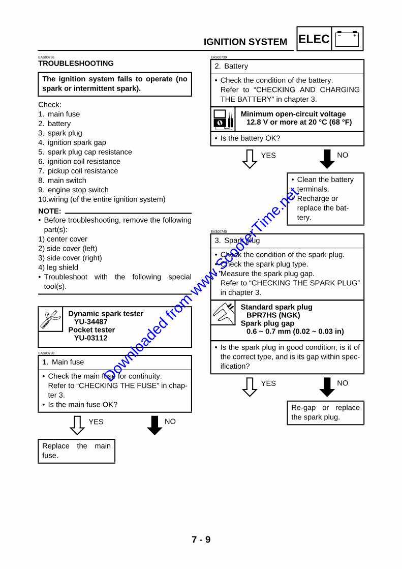
7 - 9
– +ELECIGNITION SYSTEMEAS00736
TROUBLESHOOTING
Check: 1. main fuse2. battery 3. spark plug 4. ignition spark gap 5. spark plug cap resistance 6. ignition coil resistance 7. pickup coil resistance8. main switch 9. engine stop switch 10.wiring (of the entire ignition system)
NOTE:@
• Before troubleshooting, remove the followingpart(s):
1) center cover2) side cover (left)3) side cover (right)4) leg shield• Troubleshoot with the following special
tool(s).
EAS00738
YES NO
EAS00739
YES NO
EAS00740
YES NO
The ignition system fails to operate (nospark or intermittent spark).
Dynamic spark testerYU-34487
Pocket tester YU-03112
1. Main fuse
• Check the main fuse for continuity. Refer to “CHECKING THE FUSE” in chap-ter 3.
• Is the main fuse OK?
Replace the mainfuse.
2. Battery
• Check the condition of the battery. Refer to “CHECKING AND CHARGINGTHE BATTERY” in chapter 3.
Minimum open-circuit voltage 12.8 V or more at 20 °C (68 °F)
• Is the battery OK?
• Clean the battery terminals.
• Recharge or replace the bat-tery.
3. Spark plug
• Check the condition of the spark plug. • Check the spark plug type. • Measure the spark plug gap.
Refer to “CHECKING THE SPARK PLUG”in chapter 3.
Standard spark plug BPR7HS (NGK)
Spark plug gap 0.6 ~ 0.7 mm (0.02 ~ 0.03 in)
• Is the spark plug in good condition, is it ofthe correct type, and is its gap within spec-ification?
Re-gap or replacethe spark plug.
Downlo
aded
from w
ww.Sco
oterT
ime.n
et
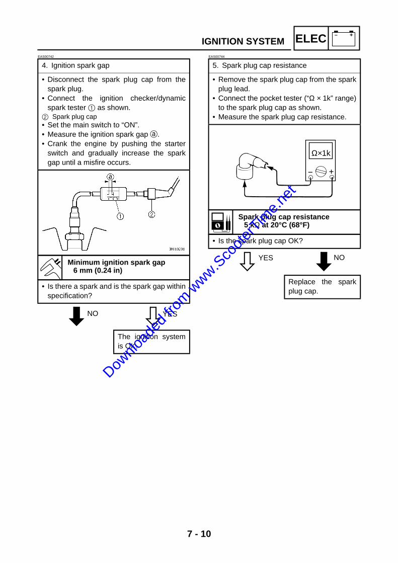
7 - 10
– +ELECEAS00742
NO YES
EAS00744
YES NO
4. Ignition spark gap
• Disconnect the spark plug cap from thespark plug.
• Connect the ignition checker/dynamicspark tester 1 as shown. 2 Spark plug cap • Set the main switch to “ON”. • Measure the ignition spark gap a. • Crank the engine by pushing the starter
switch and gradually increase the sparkgap until a misfire occurs.
Minimum ignition spark gap 6 mm (0.24 in)
• Is there a spark and is the spark gap withinspecification?
The ignition systemis OK.
5. Spark plug cap resistance
• Remove the spark plug cap from the sparkplug lead.
• Connect the pocket tester (“Ω × 1k” range)to the spark plug cap as shown.
• Measure the spark plug cap resistance.
Spark plug cap resistance 5 kΩ at 20°C (68°F)
• Is the spark plug cap OK?
Replace the sparkplug cap.
Ω×1k
IGNITION SYSTEM
Downlo
aded
from w
ww.Sco
oterT
ime.n
et

7 - 11
– +ELECEAS00746
YES NO
EAS00748
YES NO
EAS00749
YES NO
6. Ignition coil resistance
• Disconnect the ignition coil connectorsfrom the ignition coil terminals.
• Connect the pocket tester (Ω × 1) to theignition coil as shown.
Positive tester probe → orange 1Negative tester probe →
ignition coil base 2
• Measure the primary coil resistance.
Primary coil resistance 0.18 ~ 0.28 Ω at 20 °C (68 °F)
• Connect the pocket tester (Ω × 1k) to theignition coil as shown.
Negative tester probe → orange 1 Positive tester probe → spark plug lead 2
• Measure the secondary coil resistance.
Secondary coil resistance 6.32 ~ 9.48 kΩ at 20 °C (68 °F)
• Is the ignition coil OK?
Replace the ignitioncoil.
2
1
12
7. Pickup coil resistance
• Disconnect the stator coil assembly cou-pler from the wire harness.
• Connect the pocket tester (Ω × 100) to thepickup coil terminal as shown.
Positive tester probe → white/red 1 Negative tester probe → white/blue 2
• Measure the pickup coil resistance.
Pickup coil resistance 248 ~ 372 Ω at 20 °C (68 °F) (between white/red and white/blue)
• Is the pickup coil OK?
Replace the statorcoil assembly.
8. Main switch
• Check the main switch for continuity. Refer to “CHECKING THE SWITCHES”.
• Is the main switch OK?
Replace the mainswitch.
W/R W/LY/RW
1 2
IGNITION SYSTEM
Downlo
aded
from w
ww.Sco
oterT
ime.n
et

7 - 12
– +ELECEAS00750
YES NO
EAS00754
YES NO
9. Engine stop switch
• Check the engine stop switch for continu-ity. Refer to “CHECKING THE SWITCHES”.
• Is the engine stop switch OK?
Replace the righthandlebar switch.
10.Wiring
• Check the entire ignition system’s wiring. Refer to “CIRCUIT DIAGRAM”.
• Is the ignition system’s wiring properlyconnected and without defects?
Replace the ignitorunit.
Properly connect orrepair the ignitionsystem’s wiring.
IGNITION SYSTEM
Downlo
aded
from w
ww.Sco
oterT
ime.n
et

7 - 13
– +ELECELECTRIC STARTING SYSTEMEAS00755
ELECTRIC STARTING SYSTEMCIRCUIT DIAGRAM
OF
F
ON
R Br
Gy
Br
GyR
Gy
Br
RR
W
1
23
OO B
CD
BRR
R
B B B
BB
Br
BL/
WL/
Y
Y/R
W Y/R
Y/R
W/L
W/L
RR
R
RG
/Y
R L/W
4
Y/R
WB
R
R
L/W
R
G/Y
R
RR
BR
5
67
8
9
L/Y
L/W
L/W
B
L/Y
L/W
L/W
BL/
WB
L/W
B
Br G
BGB
rB
W/L
B WY
/R WW
/LW
/RY
/R
A
A
(BLA
CK
)
0
B
A B BBY/R
(BLA
CK
)
(RE
D)
(RE
D)
(BLA
CK
)
(BLA
CK
)
B
OL/
WB
rB
W/L
L/Y
E
Br
G/Y
Br
G/Y
BB
(GR
EE
N)(
GR
EE
N)
F
HI
G
Br
Br
L
G/Y
Gy/
BG
y/B
Gy
G/Y
Br
G/Y
BB
Y GGY
(GR
EE
N)(
GR
EE
N)
Z
Br B
G B
B
B
Gy
Br/
W
Br
Y
G
[BG
YT
SX
UV
W
Br
B Br/W Gy
Y Br/W Gy
Br Y
B
L Y BG
/Y BL
J
Br/
W
Br
Gy/B
Gy
Br/
W Br
Br/
W
O
N
Ch
Dg
LPPBr
Br/W Dg
L PC
h
B
LC
hBr
/WB
Dg
P(RE
D)
(RE
D)
QR
Ch
GY
GB
Y
B
B
Q
Dg B
P
Ch B
P
Dg B
B
G
Y
M
L
N
K
A
R B
R B
MAI
N HA
RNES
SW
IRE
LE
AD
1M
ain
switc
h 2
Bat
tery
3
Mai
n fu
se6
Sta
rt s
witc
h7
Eng
ine
stop
sw
itch
8S
tart
er r
elay
9S
tart
er m
otor
BC
DI u
nit
ER
ear
brak
e lig
ht s
witc
hF
Fro
nt b
rake
ligh
t sw
itch
Downlo
aded
from w
ww.Sco
oterT
ime.n
et
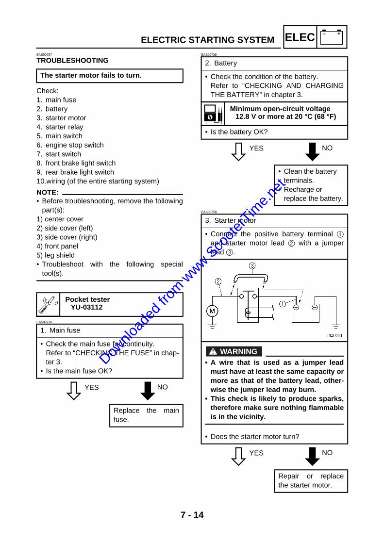
7 - 14
– +ELECELECTRIC STARTING SYSTEMEAS00757
TROUBLESHOOTING
Check: 1. main fuse 2. battery 3. starter motor 4. starter relay 5. main switch 6. engine stop switch 7. start switch 8. front brake light switch9. rear brake light switch10.wiring (of the entire starting system)
NOTE:@
• Before troubleshooting, remove the followingpart(s):
1) center cover2) side cover (left)3) side cover (right)4) front panel5) leg shield• Troubleshoot with the following special
tool(s).
EAS00738
YES NO
EAS00739
YES NO
EAS00758
YES NO
The starter motor fails to turn.
Pocket tester YU-03112
1. Main fuse
• Check the main fuse for continuity. Refer to “CHECKING THE FUSE” in chap-ter 3.
• Is the main fuse OK?
Replace the mainfuse.
2. Battery
• Check the condition of the battery. Refer to “CHECKING AND CHARGINGTHE BATTERY” in chapter 3.
Minimum open-circuit voltage 12.8 V or more at 20 °C (68 °F)
• Is the battery OK?
• Clean the battery terminals.
• Recharge or replace the battery.
3. Starter motor
• Connect the positive battery terminal 1and starter motor lead 2 with a jumperlead 3.
WARNING@
• A wire that is used as a jumper leadmust have at least the same capacity ormore as that of the battery lead, other-wise the jumper lead may burn.
• This check is likely to produce sparks,therefore make sure nothing flammableis in the vicinity.
• Does the starter motor turn?
Repair or replacethe starter motor.
Downlo
aded
from w
ww.Sco
oterT
ime.n
et
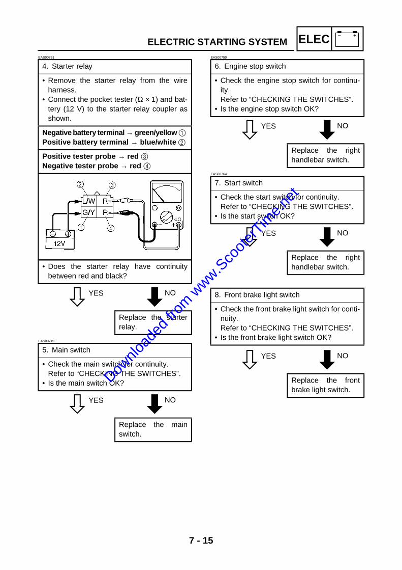
7 - 15
– +ELECEAS00761
YES NO
EAS00749
YES NO
EAS00750
YES NO
EAS00764
YES NO
YES NO
4. Starter relay
• Remove the starter relay from the wireharness.
• Connect the pocket tester (Ω × 1) and bat-tery (12 V) to the starter relay coupler asshown.
Negative battery terminal → green/yellow 1 Positive battery terminal → blue/white 2
Positive tester probe → red 3 Negative tester probe → red 4
• Does the starter relay have continuitybetween red and black?
Replace the starterrelay.
5. Main switch
• Check the main switch for continuity. Refer to “CHECKING THE SWITCHES”.
• Is the main switch OK?
Replace the mainswitch.
6. Engine stop switch
• Check the engine stop switch for continu-ity. Refer to “CHECKING THE SWITCHES”.
• Is the engine stop switch OK?
Replace the righthandlebar switch.
7. Start switch
• Check the start switch for continuity. Refer to “CHECKING THE SWITCHES”.
• Is the start switch OK?
Replace the righthandlebar switch.
8. Front brake light switch
• Check the front brake light switch for conti-nuity.Refer to “CHECKING THE SWITCHES”.
• Is the front brake light switch OK?
Replace the frontbrake light switch.
ELECTRIC STARTING SYSTEM
Downlo
aded
from w
ww.Sco
oterT
ime.n
et

7 - 16
– +ELEC
YES NO
EAS00766
YES NO
9. Rear brake light switch
• Check the rear light switch for continuity.Refer to “CHECKING THE SWITCHES”
• Is the rear brake light switch OK?
Replace the rearbrake light switch.
10.Wiring
• Check the entire starting system’s wiring. Refer to “CIRCUIT DIAGRAM”.
• Is the starting system’s wiring properlyconnected and without defects?
The starting systemcircuit is OK.
Properly connect orrepair the startingsystem’s wiring.
ELECTRIC STARTING SYSTEM
Downlo
aded
from w
ww.Sco
oterT
ime.n
et

7 - 17
– +ELECSTARTER MOTOREAS00767
STARTER MOTOR
Order Job/Part Q’ty RemarksRemoving the starter motor Remove the parts in the order listed.Air shroud Refer to “CYLINDER HEAD, CYLINDER
AND PISTON” in chapter 5.1 Starter motor coupler 12 Starter motor assembly 1
For installation, reverse the removal procedure.
Downlo
aded
from w
ww.Sco
oterT
ime.n
et

7 - 18
– +ELECEAS00768
1
2
3
4
5
6
LS
New
Order Job/Part Q’ty RemarksDisassembling the starter motor Remove the parts in the order listed.
1 O-ring 12 Starter motor yoke 13 Armature assembly 14 Gasket 25 Brush holder 16 Starter motor cover 1
For assembly, reverse the disassembly procedure.
STARTER MOTOR
Downlo
aded
from w
ww.Sco
oterT
ime.n
et

7 - 19
– +ELECSTARTER MOTOREAS00769
CHECKING THE STARTER MOTOR1. Check: • commutator
Dirt → Clean with 600-grit sandpaper.2. Measure: • commutator diameter a
Out of specification → Replace the startermotor.
Commutator wear limit 14.8 mm (0.58 in)
3. Measure: • mica undercut a
Out of specification → Scrape the mica tothe proper measurement with a hacksawblade that has been grounded to fit thecommutator.
NOTE:@
The mica must be undercut to ensure properoperation of the commutator.
4. Measure: • armature assembly resistances (commuta-
tor and insulation) Out of specification → Replace the startermotor.
a. Measure the armature assembly resis-tances with the pocket tester.
Mica undercut 1.15 mm (0.05 in)
Pocket tester YU-03112
Downlo
aded
from w
ww.Sco
oterT
ime.n
et
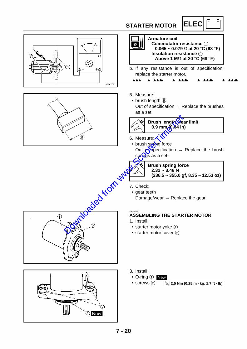
7 - 20
– +ELECSTARTER MOTOR
b. If any resistance is out of specification,replace the starter motor.
Armature coil Commutator resistance 1
0.065 ~ 0.079 Ω at 20 °C (68 °F) Insulation resistance 2
Above 1 M Ω at 20 °C (68 °F)
5. Measure: • brush length a
Out of specification → Replace the brushesas a set.
6. Measure: • brush spring force
Out of specification → Replace the brushsprings as a set.
7. Check: • gear teeth
Damage/wear → Replace the gear.
Brush length wear limit 0.9 mm (0.04 in)
Brush spring force 2.32 ~ 3.48 N (236.5 ~ 355.0 gf, 8.35 ~ 12.53 oz)
EAS00772
ASSEMBLING THE STARTER MOTOR1. Install: • starter motor yoke 1 • starter motor cover 2
3. Install: • O-ring 1 • screws 2
New
T R..
2.5 Nm (0.25 m · kg, 1.7 ft · lb)
Downlo
aded
from w
ww.Sco
oterT
ime.n
et

7 - 21
– +ELECCHARGING SYSTEMEAS00773
CHARGING SYSTEMCIRCUIT DIAGRAM
RBrGy
BrGy
R
R R W
2 3
O
B
R R R
B
B
B
B B
Br
BL/W
L/Y
Y/R
W
Y/R
Y/R
W/L W/L
RRR
RG/Y
R
L/W
4
Y/R
W B
R
R
L/W R
G/Y
R
R R BR
5
6 7
8
9
L/YL/W
L/W
B
L/Y L/WL/WBL/W
BL/WB
W/L BWY/R
WW/LW/RY/R
A
A
(BLACK)
0
B
A
BB B
Y/R
(BLACK)
(BLACK)
(BLACK)
B
O L/W BrB W/L L/Y
HI
Br
Gy/BGy/B
Gy
YGG
Y
G
B
B
Gy
Br/W
Br
Y
G
[
YT
S
U V W
Br BBr/WGy
Y
Br/WGy
BrY
B
J
Br/W
BrGy/B
Gy
Br/W
Br
Br/W
O
N
Ch Dg
LP
P
Br
Br/WDg
LP
Ch
B
L ChBr/W
B DgP
(RED) (RED)
QR
Ch
G Y
GB Y
B
B
Q
Dg
B
P
Ch
B
P
Dg
B
B
G
Y
M
L
N
K
2 Battery3 Main fuse4 Rectifier/regulator0 AC magneto
Downlo
aded
from w
ww.Sco
oterT
ime.n
et

7 - 22
– +ELECEAS00774
TROUBLESHOOTING
Check: 1. main fuse 2. battery 3. charging voltage 4. wiring (of the entire charging system)
NOTE:@
• Before troubleshooting, remove the followingpart(s):
1) center cover2) side cover (left)3) side cover (right)• Troubleshoot with the following special
tool(s).
EAS00738
YES NO
EAS00739
YES NO
EAS00775
The battery is not being charged.
Inductive tachometer YU-8036-A
Pocket tester YU-03112
1. Main fuse
• Check the main fuse for continuity. Refer to “CHECKING THE FUSE” in chap-ter 3.
• Is the main fuse OK?
Replace the mainfuse.
2. Battery
• Check the condition of the battery. Refer to “CHECKING AND CHARGINGTHE BATTERY” in chapter 3.
Minimum open-circuit voltage 12.8 V or more at 20°C (68°F)
• Is the battery OK?
• Clean the battery terminals.
• Recharge or replace the battery.
3. Charging voltage
• Connect the inductive tachometer to thespark plug lead.
• Connect the pocket tester (DC 20 V) to thebattery as shown.
Positive tester probe → positive battery terminal 1
Negative tester probe → negative battery terminal 2
• Start the engine and let it run at approxi-mately 5,000 r/min.
• Measure the charging voltage.
Charging voltage 14 V at 5,000 r/min
2
1
CHARGING SYSTEM
Downlo
aded
from w
ww.Sco
oterT
ime.n
et

7 - 23
– +ELEC
NO YES
EAS00779
YES NO
NOTE:@
Make sure the battery is fully charged.
• Is the charging voltage within specifica-tion?
The charging circuitis OK.
4. Wiring
• Check the wiring connections of the entirecharging system. Refer to “CIRCUIT DIAGRAM”.
• Is the charging system’s wiring properlyconnected and without defects?
Replace the recti-fier/regulator.
Properly connect orrepair the chargingsystem’s wiring.
CHARGING SYSTEM
Downlo
aded
from w
ww.Sco
oterT
ime.n
et
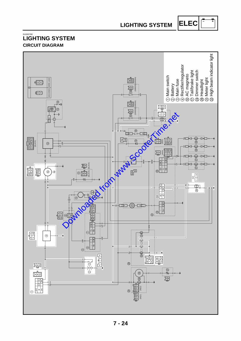
7 - 24
– +ELECLIGHTING SYSTEMEAS00780
LIGHTING SYSTEMCIRCUIT DIAGRAM
OF
F
ON
R Br
Gy
Br
GyR
Gy
Br
RR
W
1
23
OO B
CD
BRR
R
B B B
BB
Br
BL/
WL/
Y
Y/R
W Y/R
Y/R
W/L
W/L
RR
R
RG
/Y
R L/W
4
Y/R
WB
R
R
L/W
R
G/Y
R
RR
BR
5
67
8
9
L/Y
L/W
L/W
B
L/Y
L/W
L/W
BL/
WB
L/W
B
Br G
BGB
rB
W/L
B WY
/R WW
/LW
/RY
/R
A
A
(BLA
CK
)
0
B
A B BBY/R
(BLA
CK
)
(RE
D)
(RE
D)
(BLA
CK
)
(BLA
CK
)
B
OL/
WB
rB
W/L
L/Y
E
Br
G/Y
Br
G/Y
BB
(GR
EE
N)(
GR
EE
N)
F
HI
G
Br
Br
L
G/Y
Gy/
BG
y/B
Gy
G/Y
Br
G/Y
BB
Y GGY
(GR
EE
N)(
GR
EE
N)
Z
Br B
G B
B
B
Gy
Br/
W
Br
Y
G
[BG
YT
SX
UV
W
Br
B Br/W Gy
Y Br/W Gy
Br Y
B
L Y BG
/Y BL
J
Br/
W
Br
Gy/B
Gy
Br/
W Br
Br/
W
O
N
Ch
Dg
LPPBr
Br/W Dg
L PC
h
B
LC
hBr
/WB
Dg
P(RE
D)
(RE
D)
QR
Ch
GY
GB
Y
B
B
Q
Dg B
P
Ch B
P
Dg B
B
G
Y
M
L
N
K
A
R B
R B
MAI
N HA
RNES
SW
IRE
LE
AD
1M
ain
switc
h 2
Bat
tery
3M
ain
fuse
4R
ectif
ier/
regu
lato
r0
AC
mag
neto
GT
ail/b
rake
ligh
tN
Dim
mer
sw
itch
RH
eadl
ight
UM
eter
ligh
tV
Hig
h be
am in
dica
tor l
ight
Downlo
aded
from w
ww.Sco
oterT
ime.n
et

7 - 25
– +ELECEAS00782
TROUBLESHOOTING
Check: 1. main fuse2. battery 3. main switch 4. dimmer switch 5. wiring (of the entire charging system)
NOTE:@
• Before troubleshooting, remove the followingpart(s):
1) center cover2) side cover (left)3) side cover (right) 4) tail cover5) headlight cover6) front panel• Troubleshoot with the following special
tool(s).
EAS00738
YES NO
EAS00739
YES NO
EAS00749
YES NO
EAS00785
YES NO
Any of the following fail to light: Head-light, high beam indicator light, taillight,auxiliary light, and meter light.
Pocket tester YU-03112
1. Main fuse
• Check the main fuse for continuity. Refer to “CHECKING THE FUSE” in chap-ter 3.
• Is the main fuse OK?
Replace the mainfuse.
2. Battery
• Check the condition of the battery. Refer to “CHECKING AND CHARGINGTHE BATTERY” in chapter 3.
Minimum open-circuit voltage 12.8 V or more at 20°C (68°F)
• Is the battery OK?
• Clean the battery terminals.
• Recharge or replace the battery.
3. Main switch
• Check the main switch for continuity. Refer to “CHECKING THE SWITCHES”.
• Is the main switch OK?
Replace the mainswitch.
4. Dimmer switch
• Check the dimmer switch for continuity. Refer to “CHECKING THE SWITCHES”.
• Is the dimmer switch OK?
The dimmer switchis faulty. Replace the left han-dlebar switch.
LIGHTING SYSTEM
Downlo
aded
from w
ww.Sco
oterT
ime.n
et

7 - 26
– +ELECEAS00787
YES NO
EAS00788
CHECKING THE LIGHTING SYSTEM1. The headlight and the high beam indicator
light fail to come on.
YES NO
YES NO
5. Wiring
• Check the entire lighting system’s wiring. Refer to “CIRCUIT DIAGRAM”.
• Is the lighting system’s wiring properlyconnected and without defects?
Check the condi-tion of each of thelighting system’s cir-cuits. Refer to “CHECK-ING THE LIGHT-ING SYSTEM”.
Properly connect orrepair the lightingsystem’s wiring.
1. Headlight bulb and socket
• Check the headlight bulb and socket forcontinuity.
• Are the headlight bulb and socket OK?
Replace the head-light bulb, socket orboth.
2. Voltage
• Connect the pocket tester (DC 20 V) to theheadlight and high beam indicator lightcouplers as shown.
È When the dimmer switch is set to “ ”.É When the dimmer switch is set to “ ”.
Headlight coupler (wire harness side)
Positive tester probe → yellow 1 Negative tester probe → black 3
Headlight Positive tester probe →
yellow 1 or green 2Negative tester probe → black 3
High beam indicator light Positive tester probe → yellow 4 Negative tester probe → black 5
Meter light assembly coupler (wire harness side)
• Set the main switch to “ON”. • Start the engine.• Set the dimmer switch to “ ” or “ ”. • Measure the voltage (12 V) of green 2 on
the headlight coupler (wire harness side). • Is the voltage within specification?
This circuit is OK.
Br BBr/WGy
Y Br/WGy
BrY
B 4
5
LIGHTING SYSTEM
Downlo
aded
from w
ww.Sco
oterT
ime.n
et

7 - 27
– +ELECEAS00776
YES NO
EAS00789
2. The meter light fails to come on.
YES NO
YES NO
EAS00790
3. The tail/brake light fails to come on.
YES NO
4. Source coil resistance
• Disconnect the stator coil assembly cou-pler from the wire harness.
• Connect the pocket tester (Ω × 1) to thesource coils as shown.
Positive tester probe → white 1 Negative tester probe → ground 2
Positive tester probe → yellow/red 3 Negative tester probe → ground 2
• Measure the source coil resistances.
Stator coil resistance (W-B)0.29 ~ 0.43 Ω at 20°C (68°F)
• Is the stator coil OK?
The wiring circuitfrom the mainswitch to the head-light coupler isfaulty and must berepaired.
Replace the recti-fier/regulator.
1. Meter light bulb and socket
• Check the meter light bulb and socket forcontinuity.
• Are the meter light bulb and socket OK?
Replace the meterlight bulb, socket orboth.
W/R W/LY/RW1
3
2
2. Voltage
• Connect the pocket tester (20 V) to themeter light coupler (wire harness side) asshown.
Positive tester probe → brown 1 Negative tester probe → black 2
Meter light assembly coupler
• Set the main switch to “ON”. • Measure the voltage (12 V) of brown 1 on
the meter light coupler (wire harness side). • Is the voltage within specification?
This circuit is OK. The wiring circuitfrom the mainswitch to the meterlight coupler isfaulty and must berepaired.
1. Tail/brake light bulb and socket
• Check the tail/brake light bulb and socketfor continuity.
• Are the tail/brake light bulb and socketOK?
Replace the tail/brake light bulb,socket or both.
Br BBr/WGy
Y Br/WGy
BrY
B
2 1
LIGHTING SYSTEM
Downlo
aded
from w
ww.Sco
oterT
ime.n
et

7 - 28
– +ELEC
YES NO
2. Voltage
• Connect the pocket tester (DC 20 V) to thetail/brake light coupler (wire harness side)as shown.
Positive tester probe → blue 1 Negative tester probe → black 2
• Set the main switch to “ON”. • Measure the voltage (12 V) of blue 1 on
the tail/brake light coupler (tail/brake lightside).
• Is the voltage within specification?
This circuit is OK. The wiring circuitfrom the mainswitch to the tail/brake light coupleris faulty and mustbe repaired.
LYB
G/YB
L 1
2
LIGHTING SYSTEM
Downlo
aded
from w
ww.Sco
oterT
ime.n
et
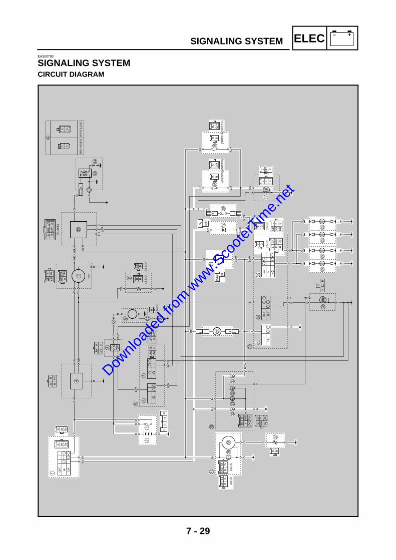
7 - 29
– +ELECEAS00793
SIGNALING SYSTEMCIRCUIT DIAGRAM
OF
F
ON
R Br
Gy
Br
GyR
Gy
Br
RR
W
1
23
OO B
CD
BRR
R
B B B
BB
Br
BL/
WL/
Y
Y/R
W Y/R
Y/R
W/L
W/L
RR
R
RG
/Y
R L/W
4
Y/R
WB
R
R
L/W
R
G/Y
R
RR
BR
5
67
8
9
L/Y
L/W
L/W
B
L/Y
L/W
L/W
BL/
WB
L/W
B
Br G
BGB
rB
W/L
B WY
/R WW
/LW
/RY
/R
A
A
(BLA
CK
)
0
B
A B BBY/R
(BLA
CK
)
(RE
D)
(RE
D)
(BLA
CK
)
(BLA
CK
)
B
OL/
WB
rB
W/L
L/Y
E
Br
G/Y
Br
G/Y
BB
(GR
EE
N)(
GR
EE
N)
F
HI
G
Br
Br
L
G/Y
Gy/
BG
y/B
Gy
G/Y
Br
G/Y
BB
Y GGY
(GR
EE
N)(
GR
EE
N)
Z
Br B
G B
B
B
Gy
Br/
W
Br
Y
G
[BG
YT
SX
UV
W
Br
B Br/W Gy
Y Br/W Gy
Br Y
B
L Y BG
/Y BL
J
Br/
W
Br
Gy/B
Gy
Br/
W Br
Br/
W
O
N
Ch
Dg
LPPBr
Br/W Dg
L PC
h
B
LC
hBr
/WB
Dg
P(RE
D)
(RE
D)
QR
Ch
GY
GB
Y
B
B
Q
Dg B
P
Ch B
P
Dg B
B
G
Y
M
L
N
K
A
R B
R B
MAI
N HA
RNES
SW
IRE
LE
AD
SIGNALING SYSTEM
Downlo
aded
from w
ww.Sco
oterT
ime.n
et
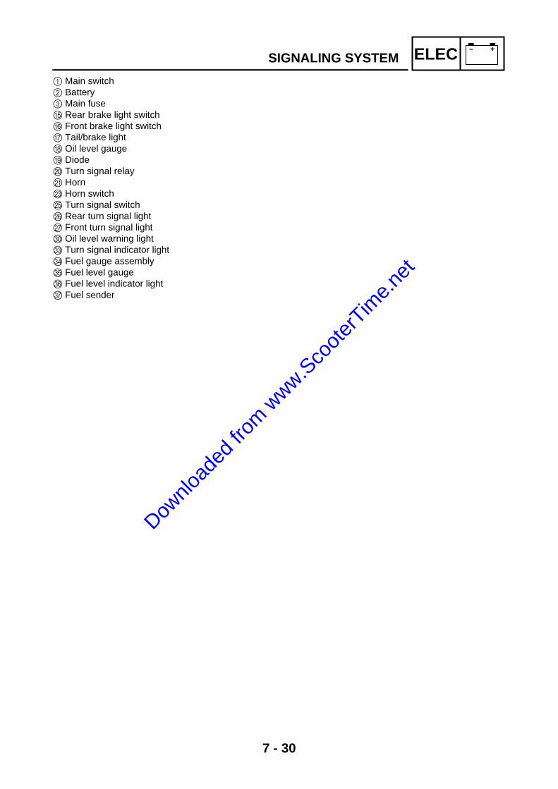
7 - 30
– +ELEC
1 Main switch 2 Battery 3 Main fuseE Rear brake light switchF Front brake light switchG Tail/brake lightH Oil level gaugeI Diode J Turn signal relayK HornM Horn switchO Turn signal switchP Rear turn signal lightQ Front turn signal lightT Oil level warning lightW Turn signal indicator lightX Fuel gauge assemblyY Fuel level gaugeZ Fuel level indicator light[ Fuel sender
SIGNALING SYSTEM
Downlo
aded
from w
ww.Sco
oterT
ime.n
et
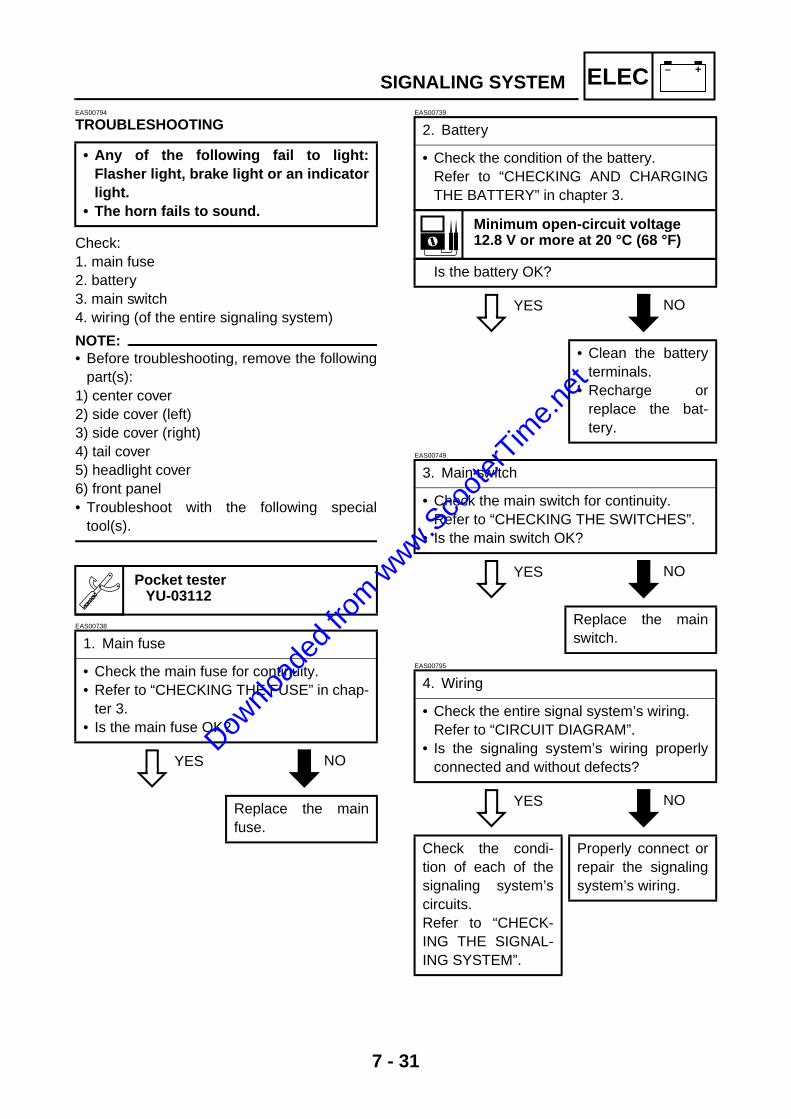
7 - 31
– +ELECEAS00794
TROUBLESHOOTING
Check: 1. main fuse 2. battery 3. main switch 4. wiring (of the entire signaling system)
NOTE:@
• Before troubleshooting, remove the followingpart(s):
1) center cover2) side cover (left)3) side cover (right) 4) tail cover5) headlight cover6) front panel• Troubleshoot with the following special
tool(s).
EAS00738
YES NO
EAS00739
YES NO
EAS00749
YES NO
EAS00795
YES NO
• Any of the following fail to light:Flasher light, brake light or an indicatorlight.
• The horn fails to sound.
Pocket tester YU-03112
1. Main fuse
• Check the main fuse for continuity. • Refer to “CHECKING THE FUSE” in chap-
ter 3. • Is the main fuse OK?
Replace the mainfuse.
2. Battery
• Check the condition of the battery. Refer to “CHECKING AND CHARGINGTHE BATTERY” in chapter 3.
Minimum open-circuit voltage 12.8 V or more at 20 °C (68 °F)
Is the battery OK?
• Clean the batteryterminals.
• Recharge orreplace the bat-tery.
3. Main switch
• Check the main switch for continuity. Refer to “CHECKING THE SWITCHES”.
• Is the main switch OK?
Replace the mainswitch.
4. Wiring
• Check the entire signal system’s wiring. Refer to “CIRCUIT DIAGRAM”.
• Is the signaling system’s wiring properlyconnected and without defects?
Check the condi-tion of each of thesignaling system’scircuits. Refer to “CHECK-ING THE SIGNAL-ING SYSTEM”.
Properly connect orrepair the signalingsystem’s wiring.
SIGNALING SYSTEM
Downlo
aded
from w
ww.Sco
oterT
ime.n
et
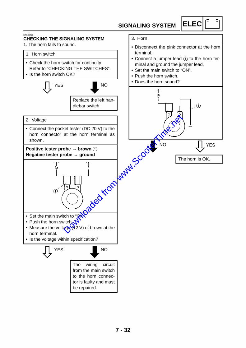
7 - 32
– +ELECEAS00796
CHECKING THE SIGNALING SYSTEM1. The horn fails to sound.
YES NO
YES NO
NO YES
1. Horn switch
• Check the horn switch for continuity. Refer to “CHECKING THE SWITCHES”.
• Is the horn switch OK?
Replace the left han-dlebar switch.
2. Voltage
• Connect the pocket tester (DC 20 V) to thehorn connector at the horn terminal asshown.
Positive tester probe → brown 1 Negative tester probe → ground
• Set the main switch to “ON”.• Push the horn switch.• Measure the voltage (12 V) of brown at the
horn terminal.• Is the voltage within specification?
The wiring circuitfrom the main switchto the horn connec-tor is faulty and mustbe repaired.
3. Horn
• Disconnect the pink connector at the hornterminal.
• Connect a jumper lead 1 to the horn ter-minal and ground the jumper lead.
• Set the main switch to “ON”.• Push the horn switch.• Does the horn sound?
The horn is OK.
SIGNALING SYSTEM
Downlo
aded
from w
ww.Sco
oterT
ime.n
et

7 - 33
– +ELEC
YES NO
EAS00798
2. The tail/brake light fails to come on.
YES NO
YES NO
YES NO
4. Voltage
• Connect the pocket tester (DC 20 V) to thehorn connector at the pink terminal asshown.
Positive tester probe → pink 1 Negative tester probe → ground
• Set the main switch to “ON”. • Measure the voltage (12 V) of pink 1 at
the horn terminal. • Is the voltage within specification?
Repair or replacethe horn.
Replace the horn.
1. Tail/brake light bulb and socket
• Check the tail/brake light bulb and socketfor continuity.
• Are the tail/brake light bulb and socketOK?
Replace the tail/brake light bulb,socket or both.
2. Brake light switches
• Check the brake light switches for continu-ity.Refer to “CHECKING THE SWITCHES”.
• Is the brake light switch OK?
Replace the brakelight switch.
3. Voltage
• Connect the pocket tester (DC 20 V) to thetail/brake light coupler (wire harness side)as shown.
Positive tester probe → green/yellow 1 Negative tester probe → black 2
• Set the main switch to “ON”. • Pull in the brake levers.• Measure the voltage (12 V) of green/yel-
low 1 on the tail/brake light coupler (wireharness side).
• Is the voltage within specification?
This circuit is OK. The wiring circuitfrom the mainswitch to the tail/brake light coupleris faulty and mustbe repaired.
LYB
G/YB
L1
2
SIGNALING SYSTEM
Downlo
aded
from w
ww.Sco
oterT
ime.n
et

7 - 34
– +ELECEAS00799
3. The turn signal light, turn signal indicatorlight or both fail to blink.
YES NO
YES NO YES NO
1. Turn signal indicator light bulb and socket
• Check the turn signal light bulb and socketfor continuity.Refer to “CHECKING THE SWITCHES”.
• Are the turn signal light bulb and socketOK?
Replace the turn sig-nal light bulb, socketor both.
2. Turn signal switch
• Check the turn signal switch for continuity.Refer to “CHECKING THE SWITCHES”.
• Is the turn signal switch OK?
Replace the left han-dlebar switch.
3. Voltage
• Connect the pocket tester (DC 20 V) to theturn signal relay coupler (wire harnessside) as shown.
Positive tester probe → brown 1 Negative tester probe → ground
• Set the main switch to “ON”. • Measure the voltage (12 V) on brown 1 at
the turn signal relay coupler (wire harnessside).
• Is the voltage within specification?
The wiring circuitfrom the main switchto the turn signalrelay coupler isfaulty and must berepaired.
Br/W
Br1
SIGNALING SYSTEM
Downlo
aded
from w
ww.Sco
oterT
ime.n
et

7 - 35
– +ELEC
YES NO
YES NO
4. Voltage
• Connect the pocket tester (DC 20 V) to theturn signal relay coupler (wire harnessside) as shown.
Positive tester probe → brown/white 1 Negative tester probe → ground
• Set the main switch to “ON”. • Set the turn signal switch to “ ” or
“ ”.• Measure the voltage (12 V) on brown/
white 1 at the turn signal relay coupler(wire harness side).
• Is the voltage within specification?
The turn signal relayis faulty and must bereplaced.
Br/W
Br
1
5. Voltage
• Connect the pocket tester (DC 20 V) to theturn signal light connector (wire harnessside) as shown.
È Turn signal light Left turn signal light
Positive tester probe → chocolate 1 Negative tester probe → ground
Right turn signal light Positive tester probe → dark green 2 Negative tester probe → ground
É Turn signal indicator lightPositive tester probe → brown 3 Negative tester probe → brown/white 4
• Set the main switch to “ON”.• Set the turn signal switch to “ ” or
“ ”.• Measure the voltage (12 V) of the choco-
late 1 or dark green 2 at the turn signallight connector (wire harness side).
• Is the voltage within specification?
This circuit is OK. The wiring circuitfrom the turn signalswitch to the turnsignal light connec-tor is faulty andmust be repaired.
Br BBr/WGy
Y Br/WGy
BrY
B
43
SIGNALING SYSTEM
È
É
Downlo
aded
from w
ww.Sco
oterT
ime.n
et

7 - 36
– +ELECEAS00802
5. The oil level warning light fails to come on.
YES NO
YES NO
YES NO
1. Oil level warning light bulb and socket
• Check the oil level warning light bulb andsocket for continuity.Refer to “CHECKING THE SWITCHES”.
• Are the oil level warning light bulb andsocket OK?
Replace the oil levelwarning light bulb,socket or both.
2. Oil level switch
• Remove the oil level switch from the oiltank.
• Connect the pocket tester (Ω × 1) to the oillevel switch.
Positive tester probe → terminal 1 Negative tester probe → terminal 2
• Check the oil level switch for continuity. • Hold the oil level switch in an upright posi-
tion È and let the float 3 go all the waydown É.
• Is the oil level switch OK?
Replace the oil levelswitch.
1 2
3
3. Diode
• Remove the diode from the wire harness.• Connect the pocket tester (Ω × 1) to the
diode terminals as shown.• Check the diode for continuity as follows.
Tester positive probe → gray 1
Tester negative probe → gray/black 2
Continu-ity
Tester positive probe → gray/black 1
Tester negative probe → gray 2
No Con-tinuity
NOTE:When you switch the tester’s positive andnegative probes, the readings in the abovechart will be reversed.
• Are the tester readings correct?
Replace the diode.
Gy/BGy
2
1
SIGNALING SYSTEM
Downlo
aded
from w
ww.Sco
oterT
ime.n
et

7 - 37
– +ELEC
YES NO
EAS00803
6. The fuel level indicator light fails to come on.
YES NO
EAS00804
YES NO
4. Voltage
• Connect the pocket tester (DC 20 V) to themeter assembly coupler (wire harnessside) as shown.
Positive tester probe → gray 1 Negative tester probe → black 2
• Set the main switch to “ON”. • Measure the voltage (12 V) of gray 1 and
black 2 at the meter assembly coupler.• Is the voltage within specification?
This circuit is OK. The wiring circuitfrom the mainswitch to the meterlight coupler isfaulty and must berepaired.
1. Fuel level indicator light bulb and socket
• Check the fuel level indicator light bulband socket for continuity.
• Are the fuel level indicator light bulb andsocket OK?
Replace the fuellevel indicator lightbulb, socket or both.
Br BBr/WGy
Y Br/WGy
BrY
B
1
2
2. Fuel sender
• Remove the fuel sender from the fuel tank.• Connect the pocket tester to the fuel
sender coupler (fuel sender side) asshown.
Positive tester probe → green 1 Negative tester probe → black 2
Fuel sender resistance (up position) È(Ω × 1) 4 ~ 10 Ω at 20 °C (68 °F)
Fuel sender resistance (down position) É(Ω × 10) 90 ~ 100 Ω at 20 °C (68 °F)
• Is the fuel sender OK?
Replace the fuelsender.
B G
2 1
SIGNALING SYSTEM
Downlo
aded
from w
ww.Sco
oterT
ime.n
et

7 - 38
– +ELEC
YES NO
YES NO
3. Fuel level gauge
• Set the main switch to “ON”.• Move the float up 1 or down 2.• Check that the fuel level gauge needle
moves to “F” or “E”.
NOTE:Before reading the fuel level meter, leavethe float in one position (either up or down)for at least three minutes.
• Does the fuel level gauge needle moveappropriately?
Replace the fuellevel gauge.
1
2
4. Voltage
• Connect the pocket tester (DC 20 V) to thefuel level gauge coupler (wire harnessside) as shown.
Fuel level gaugePositive tester probe → brown 1 Negative tester probe → green 2
Fuel level indicator lightPositive tester probe → brown 1 Negative tester probe → black 3
• Set the main switch to “ON”.• Measure the voltage (12 V) of brown 1 on
the fuel level gauge coupler (wire harnessside).
• Is the voltage within specification?
This circuit is OK. Check the wiringconnections of theentire signaling sys-tem.
SIGNALING SYSTEM
Downlo
aded
from w
ww.Sco
oterT
ime.n
et

7 - 39
– +ELECAUTO CHOKE SYSTEM
AUTO CHOKE SYSTEMCIRCUIT DIAGRAM
OO
B
B
Br
BL/W
L/Y
W
Y/R
Y/R
W/L W/L
R
W/L BWY/R
WW/LW/RY/R
LACK)
0
B
A
BB B
Y/R
(BLACK)
(BLACK)
(BLACK)
B
O L/W BrB W/L L/Y
F
Br
BrGy
BB
J
BrGy/B
Gy
Br/W
0 AC magnetoA Auto choke
Downlo
aded
from w
ww.Sco
oterT
ime.n
et

7 - 40
– +ELEC
TROUBLESHOOTING
Check:1. auto choke resistance2. lighting coil resistance3. voltage
NOTE:@
• Before troubleshooting, remove the followingpart(s):
1) center cover• Troubleshoot with the following special
tool(s).
YES NO
YES NO
The auto choke fails to operate
Pocket tester YU-03112
1. Auto choke resistance
• Disconnect the auto choke coupler fromthe wire harness.
• Connect the pocket tester (Ω × 1) to theauto choke coupler as shown.
Tester positive probe → black 1 Tester negative probe → black 2
Auto choke resistance8 ~ 12 Ω at 20 °C (68 °F)
• Is the auto choke unit OK?
Replace the autochoke.
B B2 1
2. Source coil resistance
• Disconnect the stator coil assembly cou-pler from wire harness.
• Connect the pocket tester (Ω × 1) to thesource coil lead.
Tester positive probe → yellow/red 1 Tester negative probe → ground 2
Source coil resistance0.18 ~ 0.28 Ω at 20 °C (68 °F)
Replace the statorcoil assembly.
W/R W/LY/RW
1
2
AUTO CHOKE SYSTEM
Downlo
aded
from w
ww.Sco
oterT
ime.n
et

7 - 41
– +ELEC
YES NO
3. Voltage
• Connect the pocket tester (AC 20 V) to theauto choke lead.
Tester positive probe → yellow/red 1Tester negative probe → black 2
• Set the main switch to “ON”.• Start the engine and accelerate to about
3,000 r/min• Check the voltage.
Voltage 12.8 V or more at 20 °C (68 °F)
This auto choke isOK.
Check the entireauto choke unit forconnection.Refer to the “CIR-CUIT DIAGRAM”.
B B
B Y/R
2
1
AUTO CHOKE SYSTEM
Downlo
aded
from w
ww.Sco
oterT
ime.n
et

Downlo
aded
from w
ww.Sco
oterT
ime.n
et

TRBLSHTG 8Dow
nload
ed fro
m www.S
coote
rTim
e.net
TRBLSHTG
CHAPTER 8TROUBLESHOOTING
STARTING FAILURE/HARD STARTING .......................................................8-1ENGINE.....................................................................................................8-1FUEL SYSTEM..........................................................................................8-1ELECTRICAL SYSTEMS ..........................................................................8-1
INCORRECT ENGINE IDLING SPEED...........................................................8-2ENGINE.....................................................................................................8-2FUEL SYSTEM..........................................................................................8-2ELECTRICAL SYSTEMS ..........................................................................8-2
POOR MEDIUM-AND-HIGH-SPEED PERFORMANCE .................................8-2ENGINE.....................................................................................................8-2FUEL SYSTEM..........................................................................................8-2
FAULTY CLUTCH ...........................................................................................8-2ENGINE OPERATES BUT SCOOTER WILL NOT MOVE........................8-2CLUTCH SLIPS.........................................................................................8-2POOR STARTING PERFORMANCE........................................................8-2POOR ACCELERATION PERFORMANCE ..............................................8-2
OVERHEATING ...............................................................................................8-3ENGINE.....................................................................................................8-3FUEL SYSTEM..........................................................................................8-3CHASSIS...................................................................................................8-3ELECTRICAL SYSTEMS ..........................................................................8-3
POOR BRAKING PERFORMANCE ................................................................8-3
UNSTABLE HANDLING ..................................................................................8-3
FAULTY LIGHTING OR SIGNALING SYSTEM ..............................................8-4HEADLIGHT DOES NOT LIGHT...............................................................8-4HEADLIGHT BULB BURNT OUT..............................................................8-4TAIL/BRAKE LIGHT DOES NOT LIGHT...................................................8-4TAIL/BRAKE LIGHT BULB BURNT OUT..................................................8-4TURN SIGNAL DOES NOT LIGHT ...........................................................8-4TURN SIGNAL BLINKS SLOWLY.............................................................8-4TURN SIGNAL REMAINS LIT...................................................................8-4TURN SIGNAL BLINKS QUICKLY............................................................8-4HORN DOES NOT SOUND ......................................................................8-4
Downlo
aded
from w
ww.Sco
oterT
ime.n
et

TRBLSHTG
Downlo
aded
from w
ww.Sco
oterT
ime.n
et

8 - 1
TRBLSHTG
EAS00845
TROUBLESHOOTINGNOTE:@
The following guide for troubleshooting does not cover all the possible causes of trouble. It shouldbe helpful, however, as a guide to basic troubleshooting. Refer to the relative procedure in this man-ual for checks, adjustments, and replacement of parts.
STARTING FAILURE/HARD STARTINGENGINECylinder and cylinder head• Loose spark plug • Loose cylinder head or cylinder • Damaged cylinder head gasket • Damaged cylinder gasket • Worn or damaged cylinder
Piston and piston ring(s)• Improperly installed piston ring • Damaged, worn or fatigued piston ring • Seized piston ring • Seized or damaged piston
Air filter• Improperly installed air filter • Clogged air filter element
Crankcase and crankshaft• Improperly assembled crankcase • Seized crankshaft
FUEL SYSTEMFuel tank• Empty fuel tank • Clogged fuel tank cap breather hole • Deteriorated or contaminated fuel • Clogged or damaged fuel hose
Carburetor• Deteriorated or contaminated fuel • Clogged pilot jet • Clogged pilot air passage • Sucked-in air • Damaged float • Worn needle valve • Improperly installed needle valve seat • Incorrect fuel level • Improperly adjusted pilot air screw • Improperly installed pilot jet • Clogged starter jet • Clogged emulsion tube
Autochoke unit• Faulty starter plunger • Faulty ignitor unit
ELECTRICAL SYSTEMSBattery• Improperly charged battery • Faulty battery
Fuse• Blown, damaged or incorrect fuse • Improperly installed fuse
Spark plug• Incorrect spark plug gap • Incorrect spark plug heat range • Fouled spark plug • Worn or damaged electrode • Worn or damaged insulator • Faulty spark plug cap
Ignition coil• Broken or shorted primary or secondary coil • Faulty spark plug lead • Cracked or broken ignition coil body
Ignition system• Faulty ignitor unit • Faulty pickup coil • Broken generator rotor woodruff key
Switches and wiring• Faulty main switch • Faulty engine stop switch • Broken or shorted wiring • Faulty front, rear or both brake switches • Faulty start switch • Improperly grounded circuit • Loose connections
Starting system• Faulty starter motor • Faulty starter relay • Faulty starter clutch
STARTING FAILURE/HARD STARTING
Downlo
aded
from w
ww.Sco
oterT
ime.n
et
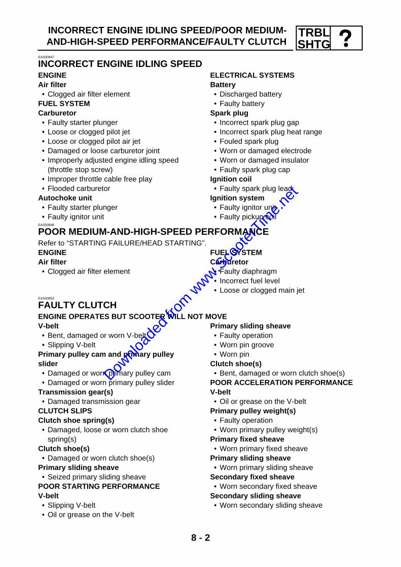
8 - 2
TRBLSHTG
INCORRECT ENGINE IDLING SPEED/POOR MEDIUM-AND-HIGH-SPEED PERFORMANCE/FAULTY CLUTCH
EAS00847
INCORRECT ENGINE IDLING SPEEDENGINEAir filter• Clogged air filter element
FUEL SYSTEMCarburetor• Faulty starter plunger • Loose or clogged pilot jet • Loose or clogged pilot air jet • Damaged or loose carburetor joint • Improperly adjusted engine idling speed
(throttle stop screw) • Improper throttle cable free play • Flooded carburetor
Autochoke unit• Faulty starter plunger • Faulty ignitor unit
ELECTRICAL SYSTEMSBattery• Discharged battery • Faulty battery
Spark plug• Incorrect spark plug gap • Incorrect spark plug heat range • Fouled spark plug • Worn or damaged electrode • Worn or damaged insulator • Faulty spark plug cap
Ignition coil• Faulty spark plug lead
Ignition system• Faulty ignitor unit • Faulty pickup coil
EAS00848
POOR MEDIUM-AND-HIGH-SPEED PERFORMANCERefer to “STARTING FAILURE/HEAD STARTING”.ENGINEAir filter• Clogged air filter element
FUEL SYSTEMCarburetor• Faulty diaphragm • Incorrect fuel level • Loose or clogged main jet
EAS00853
FAULTY CLUTCHENGINE OPERATES BUT SCOOTER WILL NOT MOVEV-belt• Bent, damaged or worn V-belt • Slipping V-belt
Primary pulley cam and primary pulley slider• Damaged or worn primary pulley cam • Damaged or worn primary pulley slider
Transmission gear(s)• Damaged transmission gear
CLUTCH SLIPSClutch shoe spring(s)• Damaged, loose or worn clutch shoe
spring(s)Clutch shoe(s)• Damaged or worn clutch shoe(s)
Primary sliding sheave• Seized primary sliding sheave
POOR STARTING PERFORMANCEV-belt• Slipping V-belt• Oil or grease on the V-belt
Primary sliding sheave• Faulty operation • Worn pin groove • Worn pin
Clutch shoe(s)• Bent, damaged or worn clutch shoe(s)
POOR ACCELERATION PERFORMANCEV-belt• Oil or grease on the V-belt
Primary pulley weight(s)• Faulty operation • Worn primary pulley weight(s)
Primary fixed sheave• Worn primary fixed sheave
Primary sliding sheave• Worn primary sliding sheave
Secondary fixed sheave• Worn secondary fixed sheave
Secondary sliding sheave• Worn secondary sliding sheave
Downlo
aded
from w
ww.Sco
oterT
ime.n
et

8 - 3
TRBLSHTG
OVERHEATING/POOR BRAKING PERFORMANCE/UNSTABLE HANDLING
EAS00854
OVERHEATINGENGINECylinder head and piston• Heavy carbon buildup
Engine oil and transmission oil• Incorrect oil level • Incorrect oil viscosity • Inferior oil quality
FUEL SYSTEMCarburetor• Incorrect main jet setting • Incorrect fuel level • Damaged or loose carburetor joint
Air filter• Clogged air filter element
CHASSISBrake(s)• Dragging brake
ELECTRICAL SYSTEMSSpark plug• Incorrect spark plug gap • Incorrect spark plug heat range
Ignition system• Faulty ignitor unit
EAS00858
POOR BRAKING PERFORMANCE• Worn brake shoe lining• Worn or rusty brake drum • Incorrect brake lever position • Incorrect brake lever free play • Incorrect brake camshaft lever position
• Incorrect brake shoe position • Damaged or fatigued brake shoe spring • Oil or grease on the brake shoe • Oil or grease on the brake drum • Broken brake torque rod
EAS00862
UNSTABLE HANDLINGHandlebar• Bent or improperly installed handlebar
Steering head components• Improperly installed lower handlebar holder• Improperly installed fork
(improperly tightened ring nut) • Bent steering stem • Damaged ball bearing or bearing race
Front shock absorber assembly (-ies)• Faulty front shock absorber spring(s)• Leaking oil
Rear shock absorber assembly• Faulty rear shock absorber spring • Leaking oil
Tire(s)• Uneven tire pressures (front and rear) • Incorrect tire pressure • Uneven tire wear
Wheel(s)• Incorrect wheel balance • Deformed cast wheel • Damaged wheel bearing • Bent or loose wheel axle • Excessive wheel runout
Frame• Bent frame • Damaged steering head pipe • Improperly installed bearing race
Downlo
aded
from w
ww.Sco
oterT
ime.n
et

8 - 4
TRBLSHTGFAULTY LIGHTING OR SIGNALING SYSTEM
EAS00866
FAULTY LIGHTING OR SIGNALING SYSTEMHEADLIGHT DOES NOT LIGHT• Wrong headlight bulb • Too many electrical accessories • Hard charging • Incorrect connection • Improperly grounded circuit • Poor contacts (main switch) • Burnt-out headlight bulb
HEADLIGHT BULB BURNT OUT• Wrong headlight bulb • Faulty battery • Faulty rectifier/regulator • Improperly grounded circuit • Faulty main switch • Headlight bulb life expired
TAIL/BRAKE LIGHT DOES NOT LIGHT• Wrong tail/brake light bulb • Too many electrical accessories • Incorrect connection • Burnt-out tail/brake light bulb
TAIL/BRAKE LIGHT BULB BURNT OUT• Wrong tail/brake light bulb • Faulty battery • Tail/brake light bulb life expired
TURN SIGNAL DOES NOT LIGHT• Faulty turn signal switch • Faulty turn signal relay • Burnt-out turn signal bulb • Incorrect connection • Damaged or faulty wire harness • Improperly grounded circuit • Faulty battery • Blown, damaged or incorrect fuse
TURN SIGNAL BLINKS SLOWLY• Faulty turn signal relay • Faulty main switch • Faulty turn signal switch • Incorrect turn signal bulb
TURN SIGNAL REMAINS LIT• Faulty turn signal relay • Burnt-out turn signal bulb
TURN SIGNAL BLINKS QUICKLY• Incorrect turn signal bulb • Faulty turn signal relay • Burnt-out turn signal bulb
HORN DOES NOT SOUND• Improperly adjusted horn • Damaged or faulty horn • Faulty main switch • Faulty horn switch • Faulty battery • Blown, damaged or incorrect fuse • Faulty wire harness
Downlo
aded
from w
ww.Sco
oterT
ime.n
et

YJ50RN WIRING DIAGRAM1 Main switch2 Battery3 Main fuse4 Rectifier/regulator5 Right handlebar switch6 Start switch7 Engine stop switch8 Starter relay9 Starter motor0 AC magnetoA Auto chokeB CDI unitC Ignition coilD Spark plugE Rear brake light switchF Front brake light switchG Tail/brake lightH Oil level gaugeI DiodeJ Turn signal relayK HornL Left handlebar switchM Horn switchN Dimmer switchO Turn signal switchP Rear turn signal lightQ Front turn signal lightR HeadlightS Meter assemblyT Oil level warning lightU Meter lightV High beam indicator lightW Turn signal indicator lightX Fuel gauge assemblyY Fuel level gaugeZ Fuel level indicator light[ Fuel sender
OFF
ON
RBrGy
BrGy
R
Gy Br
R R W
1
2 3
OO
B
C D
B
R R R
B
B
B
B B
Br
BL/W
L/Y
Y/R
W
Y/R
Y/R
W/L W/L
RRR
RG/Y
R
L/W
4
Y/R
W B
R
R
L/W R
G/Y
R
R R BR
5
6 7
8
9
L/YL/W
L/W
B
L/Y L/WL/WBL/W
BL/WB
BrGBG
BrB
W/L BWY/R
WW/LW/RY/R
A
A
(BLACK)
0
B
A
BB B
Y/R
(BLACK)
(RED)(RED)
(BLACK)
(BLACK)
B
O L/W BrB W/L L/Y
E
Br
G/Y
BrG/YB
B
(GREEN)(GREEN)
F
HI
G
Br
Br
L
G/Y
Gy/BGy/B
Gy
G/Y
BrG/YB
B
YGG
Y
BG
(GREEN)(GREEN)
Z
Br
B G
B
B
B
Gy
Br/W
Br
Y
G
[
YT
SX
U V W
Br BBr/WGy
Y
Br/WGy
BrY
B
LYB
G/YB
L
J
Br/W
BrGy/B
Gy
Br/W
Br
Br/W
O
N
Ch Dg
LP
P
Br
Br/WDg
LP
Ch
B
L ChBr/W
B DgP
(RED) (RED)
QR
Ch
G Y
GB Y
B
B
Q
Dg
B
P
Ch
B
P
Dg
B
B
G
Y
M
L
N
K
A
R
B
R
B
MAIN HARNESS WIRE LEAD
COLOR CODEB ............blackBr ...........brownCh ..........chocolateDg ..........dark greenG............green
Gy.......... grayL ............ blueO ........... orangeP............ pinkR............ red
W ...........whiteY ............yellowBr/W.......brown/whiteG/Y ........green/yellowGy/B.......gray/black
L/W ....... blue/whiteL/Y ........ blue/yellowW/L ....... white/blueW/R....... white/redY/R........ yellow/red
Downlo
aded
from w
ww.Sco
oterT
ime.n
et

Yamaha Motor Canada Ltd.480 Gordon Baker RoadToronto, ON M2H 3B4
Downlo
aded
from w
ww.Sco
oterT
ime.n
et