Numerical diffusive terms in weakly-compressible SPH schemes
Chemical Engineering Research Bulletin 13 (2009) 17-24 Available online at http://www.banglajol.info/index.php/CERB
DOUBLE DIFFUSIVE MIXED CONVECTION HEAT TRANSFER INSIDE AVENTED SQUARE CAVITY
Sumon Saha∗,1, Mohammad Nasim Hasan2, Iftheker Ahmed Khan3
1Department of Mechanical Engineering, The University of Melbourne, Victoria-3010, Australia2Department of Mechanical Engineering, Saga University, 1 Honjo-machi, Saga 840-8502, Japan
3Department of Civil & Environmental Engineering, University of South Carolina, Columbia, SC 29208, USA
Received 23 March 2009; received in revised form 1 September 2009
Abstract: A numerical study has been carried out for laminar double-diffusive mixed convection in a two-dimensional vented square cavity with discrete heat and contaminant sources applied on the bottom wall. Anexternal air flow enters the cavity through an opening located at the bottom of the left vertical wall and exits froman opening located at the three different positions of the opposite wall. The developed mathematical model isgoverned by the two-dimensional continuity, momentum, energy, and concentration equations. The governingequations, written in non-dimensional form are solved by using Galerkin finite element method with triangulargrid discretization system. The Reynolds number is fixed at 100 and the working fluid is considered as air.Numerical simulations are carried out for different combinations of the thermal Grashof numbers and resultsare presented in terms of streamlines, temperature and concentration distributions. The results indicate that theaverage Nusselt and Sherwood numbers on the heat and contaminant sources strongly depend on the positioningof the exit opening.
Keywords: double diffusive mixed convection, vented cavity, finite element
DOI:10.3329/cerb.v13i1.2512
1. Introduction
Double diffusive mixed convection in cavities hasbeen subject of an intensive research due to its im-portance in various engineering and geophysical prob-lems. This includes nuclear reactors, solar ponds,lakes and reservoirs, solar collectors and crystalgrowth. Nowadays, control of indoor air environmentis becoming a cutting-edge issue for study of doublediffusive mixed convection in a ventilated room. Sev-eral discrete heat and contaminant sources, such aspets, cooking, smoking, burning furnace, blazing win-dow, office automation equipments, and building ma-terials and furnishings, which intermittently or con-tinuously produce allergens, heat, gas components(CO2, CO, NOx), particulate matter (PM10, PM2.5),and volatile organic compounds (VOCs) within aventilated room [1, 2]. There exist two differenttypes of convection in a vented cavity; namely in-ternal buoyancy-induced natural convection by thediscrete heat and contaminant sources and externalmechanical-driven forced convection by the ventila-tion. The fluid flow and heat or contaminant transfercharacteristics inside the vented cavity are thus foundby the interaction between the natural convection andthe force one, which results in double diffusive mixedconvection.
∗Corresponding author Email: [email protected]
A literature review concerning ventilated enclosuresshows that some available works have considered theproblem of mixed convection in rectangular cavities.Papanicolaou and Jaluria [3–7] carried out a seriesof numerical studies in order to investigate the com-bined forced and natural convective cooling of heat-dissipating electronic components located in a rectan-gular enclosure, and cooled by an external through-flow of air. Laminar mixed convection in a two-dimensional enclosure heated from one sidewall andsubmitted to an either aiding or opposing jet was nu-merically studied in the work of Angirasa [8] and Rajiand Hasnaoui [9, 10]. Later, Raji and Hasnaoui [11]investigated the mixed convection in ventilated cavi-ties where the horizontal top wall and the vertical leftwall were prescribed with equal heat fluxes. Similarinvestigations were also carried out by the same au-thors taking into consideration the effect of the thermalradiation on mixed convection [12].
A numerical study of an enclosure with a heatedvertical plate located in the cavity was carried out byHsu and Ang [13]. Discrete heat sources were em-bedded on the plate and different orientations wereconsidered. When the heat source was embedded onthe surface of the board opposite to forced flow in-let; the value of the convective Nusselt number wasfound to be independent of the location of the heatsource. Omri and Nasrallah [14]studied mixed con-
c©Bangladesh Uni. of Engg. & Tech.
18 Chemical Engineering Research Bulletin 13(2009) 17-24 / Saha et al.
vection in a rectangular enclosure with differentiallyheated vertical sidewalls having openings for inlet andoutlet. Two different placement configurations of theinlet and outlet openings on the side walls were inves-tigated. In the first case, the cold air was injected at thetop of the hot wall and exited at the bottom of the coldwall, whereas in the second configuration the injectionwas at the lower edge of the hot wall and the exit wasat the top of the cold wall. Improvement in coolingefficiency was found with the inlet placed at the bot-tom of the hot wall. Similar investigations were alsocarried out by Singh and Sharif [15] considering sixplacement configurations of the inlet and outlet open-ings. They observed that maximum cooling effective-ness was achieved if the inlet was kept near the bottomof the cold wall while the outlet was placed near thetop of the hot wall. Recently Saha et al. [16] carriedout similar numerical experiments for mixed convec-tion in a vented enclosure with constant heat flux heat-ing from below. Four different locations of inlet andoutlet openings were introduced to analyze the effectof heat transfer mechanism and their results criticallyexplained the importance of the orientation of the inletand exit ports in a vented enclosure. Further investiga-tions on the same topic were carried out by Saha et al.with the same geometric configurations but consider-ing isoflux heating at the right sidewall [17].
The effects of combined thermal and solutal buoy-ancy induced by temperature and concentration gra-dients have, however, not been widely studied. Yan[18, 19] and Lee et al. [20] analyzed the transport phe-nomena of developing laminar mixed convection heatand mass transfer in rectangular ducts. Later, Alimiet al. [21] studied the buoyancy effects on mixed con-vection heat and mass transfer in an inclined duct pre-ceded with a double step expansion. Brown and Lai[22] numerically examined combined heat and masstransfer from a horizontal channel with an open cav-ity heated from below. Since heat and contaminantsources usually co-exist indoors, the present work isto numerically study the double-diffusive mixed con-vection in a vented cavity due to the discrete heat andcontaminant sources. As far as authors know, the prob-lem has never been concerned in the public literaturesuntil Deng et al. [23] performed a similar investigationof the similar problem inside a ventilated enclosure.However, a detailed investigation is still deserved tounderstand the effect of exit port location on the in-door air environment. Therefore, the objective of thepresent work is to investigate the new characteristicsof the airflow and heat/contaminant transport mecha-nism inside a vented cavity in terms of streamlines,isotherms and isoconcentration lines.
2. Analysis
2.1. Physical Model
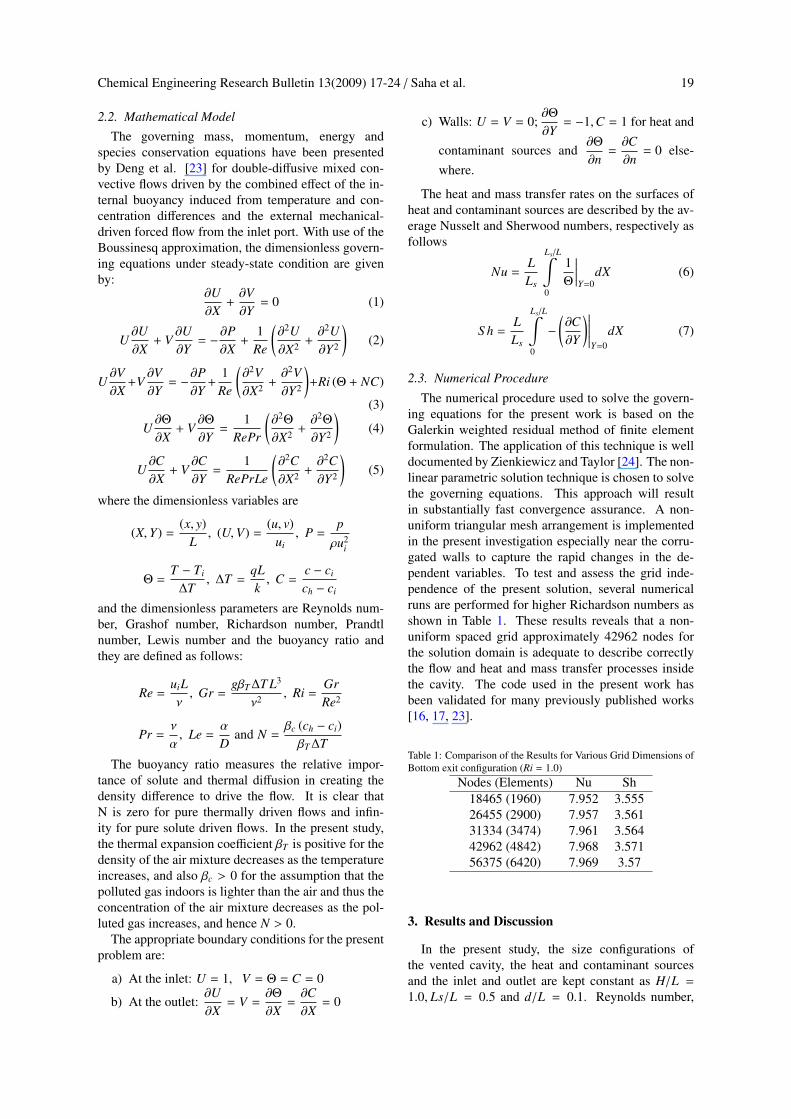
The domain under analysis is, as sketched in Figure1, a square two-dimensional cavity, suffering the influ-ence of a gravitational field. An isoflux heat source, qof size Ls and a contaminant source of equal size andhigh concentration ch locate on the right part of thebottom wall. The remaining top, bottom and sidewallsare assumed to be adiabatic and impermeable. Theinflow opening of size d is located on the lower leftvertical wall while the location of the equal size out-flow opening is varied in three different arrangementsof the right vertical wall as shown in Figure 1 (a), (b)and (c). Low speed fresh cold air (ui, Ti, ci) is injectedthrough the inlet opening in the horizontal directionand then the polluted hot air exhausted from the out-let opening at the right side wall. Hence the outflowis assumed to have zero diffusion flux for all variables(outflow boundary condition [OBC]).
(a) bottom exit configuration
(b) middle exit configuration
(c) top exit configuration
Figure 1: Schematic diagram for the problem with boundary condi-tion
Chemical Engineering Research Bulletin 13(2009) 17-24 / Saha et al. 19
2.2. Mathematical ModelThe governing mass, momentum, energy and
species conservation equations have been presentedby Deng et al. [23] for double-diffusive mixed con-vective flows driven by the combined effect of the in-ternal buoyancy induced from temperature and con-centration differences and the external mechanical-driven forced flow from the inlet port. With use of theBoussinesq approximation, the dimensionless govern-ing equations under steady-state condition are givenby:
∂U∂X
+∂V∂Y
= 0 (1)
U∂U∂X
+ V∂U∂Y
= −∂P∂X
+1
Re
(∂2U∂X2 +
∂2U∂Y2
)(2)
U∂V∂X
+V∂V∂Y
= −∂P∂Y
+1
Re
(∂2V∂X2 +
∂2V∂Y2
)+Ri (Θ + NC)
(3)
U∂Θ
∂X+ V
∂Θ
∂Y=
1RePr
(∂2Θ
∂X2 +∂2Θ
∂Y2
)(4)
U∂C∂X
+ V∂C∂Y
=1
RePrLe
(∂2C∂X2 +
∂2C∂Y2
)(5)
where the dimensionless variables are
(X,Y) =(x, y)
L, (U,V) =
(u, v)ui
, P =pρu2
i
Θ =T − Ti
∆T, ∆T =
qLk, C =
c − ci
ch − ci
and the dimensionless parameters are Reynolds num-ber, Grashof number, Richardson number, Prandtlnumber, Lewis number and the buoyancy ratio andthey are defined as follows:
Re =uiLν, Gr =
gβT ∆T L3
ν2 , Ri =GrRe2
Pr =ν
α, Le =
α
Dand N =
βc (ch − ci)βT ∆T
The buoyancy ratio measures the relative impor-tance of solute and thermal diffusion in creating thedensity difference to drive the flow. It is clear thatN is zero for pure thermally driven flows and infin-ity for pure solute driven flows. In the present study,the thermal expansion coefficient βT is positive for thedensity of the air mixture decreases as the temperatureincreases, and also βc > 0 for the assumption that thepolluted gas indoors is lighter than the air and thus theconcentration of the air mixture decreases as the pol-luted gas increases, and hence N > 0.
The appropriate boundary conditions for the presentproblem are:
a) At the inlet: U = 1, V = Θ = C = 0
b) At the outlet:∂U∂X
= V =∂Θ
∂X=∂C∂X
= 0
c) Walls: U = V = 0;∂Θ
∂Y= −1,C = 1 for heat and
contaminant sources and∂Θ
∂n=∂C∂n
= 0 else-where.
The heat and mass transfer rates on the surfaces ofheat and contaminant sources are described by the av-erage Nusselt and Sherwood numbers, respectively asfollows
Nu =LLs
Ls/L∫0
1Θ
∣∣∣∣∣Y=0
dX (6)
S h =LLs
Ls/L∫0
−
(∂C∂Y
)∣∣∣∣∣∣Y=0
dX (7)
2.3. Numerical Procedure
The numerical procedure used to solve the govern-ing equations for the present work is based on theGalerkin weighted residual method of finite elementformulation. The application of this technique is welldocumented by Zienkiewicz and Taylor [24]. The non-linear parametric solution technique is chosen to solvethe governing equations. This approach will resultin substantially fast convergence assurance. A non-uniform triangular mesh arrangement is implementedin the present investigation especially near the corru-gated walls to capture the rapid changes in the de-pendent variables. To test and assess the grid inde-pendence of the present solution, several numericalruns are performed for higher Richardson numbers asshown in Table 1. These results reveals that a non-uniform spaced grid approximately 42962 nodes forthe solution domain is adequate to describe correctlythe flow and heat and mass transfer processes insidethe cavity. The code used in the present work hasbeen validated for many previously published works[16, 17, 23].
Table 1: Comparison of the Results for Various Grid Dimensions ofBottom exit configuration (Ri = 1.0)
Nodes (Elements) Nu Sh18465 (1960) 7.952 3.55526455 (2900) 7.957 3.56131334 (3474) 7.961 3.56442962 (4842) 7.968 3.57156375 (6420) 7.969 3.57
3. Results and Discussion
In the present study, the size configurations ofthe vented cavity, the heat and contaminant sourcesand the inlet and outlet are kept constant as H/L =
1.0, Ls/L = 0.5 and d/L = 0.1. Reynolds number,

20 Chemical Engineering Research Bulletin 13(2009) 17-24 / Saha et al.
Prandtl number, Lewis number and the buoyancy ratioare kept fixed at 100, 0.7, 1 and 1 respectively. Threedifferent locations (bottom, middle and top) of the out-let port are considered in the present investigation.Moreover, main attention is then focused on the effectsof the governing parameter, Richardson number on theindoor air mixed convection. The range of Richard-son number used for the simulations is 0.1 ≤ Ri ≤ 10and it is obtained by varying the Grashof number only.Now in the following section, a detailed descriptionof mixed convection with heat and mass transfer in avented cavity is given in terms of streamline, thermaland concentration contours for three different exit portconfigurations. In addition, the results for both aver-age Nusselt and average Sherwood numbers at variousconditions will be presented and discussed.
3.1. Bottom Exit Configuration
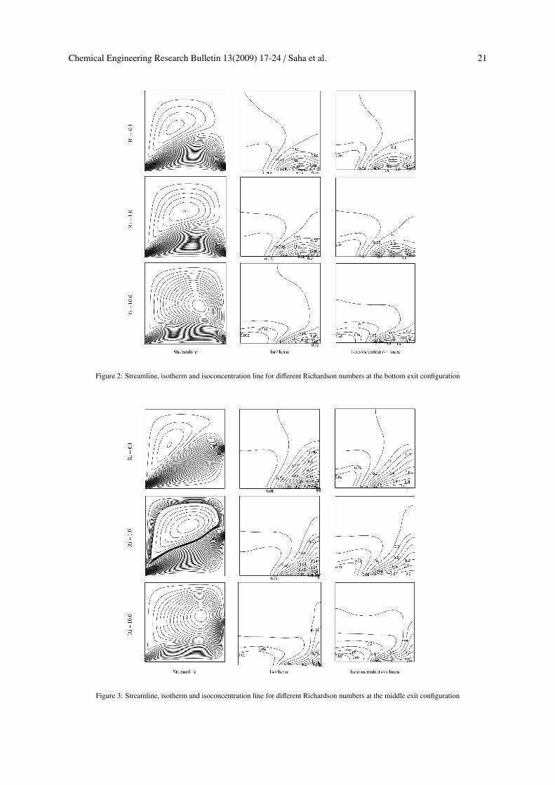
Figure 2 presents the effect of Richardson numberon the streamline, isothermals and isoconcentrationcontours for bottom exit configuration. In this figurethe effect of both thermal buoyancy force and solutalbuoyancy force are equal. Therefore, the double dif-fusive flow is applicable. The streamlines describe theinteraction of forced and natural convection under var-ious convection regimes. To assess the influence ofbuoyancy effects on the mixed convection flow, the re-sults of the limiting case of purely forced convectionare also included in Figure 2. At Re = 100, for thelower Ri values, forced convection dominates the ma-jor flow from the inlet to the exit without much pene-trating into the cavity. At Ri = 0.1, the bulk inducedflow expands in the cavity resulting increase in poten-tial energy. Heat is carried out merely by forced con-vection. A recirculating cell of low velocity is formedwhich occupies half of the cavity. It is of interest tonote that both Θ and C develop in a very similar way.This is simply because the Le and N in the gas flow istaken as unity. Careful inspection, however, disclosesthat the mass-fraction boundary layers develop a lit-tle more rapidly than the temperature boundary layers.This is simply due to the fact that the isoflux heatingboundary condition is much different than the uniformisoconcentration contaminant source boundary condi-tion. With increased dominance of natural convectionat Ri = 10, the cold incoming air and the hot vortexstart to mix up and carry the heat to the bulk of thecavity. Besides, an increase in the value of Ri, throughan increase in Gr, leads to denser isothermal lines be-cause of the increasing recirculation. Thus the isother-mal lines concentrate at the heat source for Ri = 10 asshown in the last row of Figure 2.
Making a comparison of isoconcentration lines forvarious Ri, no significant difference is found exceptthat the dense isoconcentration lines at low Ri areshifted towards right exit corner. This forms a strong
assisted flow for the species concentration, thereby fa-ciliting mass transport out through the exit. There ishardly any distortion in the thermal and concentrationfields until the buoyancy and inertia forces becomeequally dominant at Ri = 1. In fact, high Richard-son number on the other hand decreases the boundarylayer in the vicinity of right part of the bottom wall.
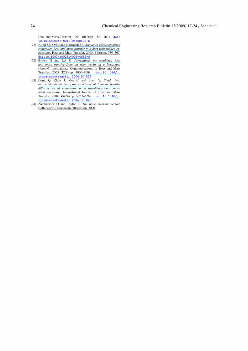
3.2. Middle Exit ConfigurationSimilar representations of the fluid, heat and mass
flow behavior inside a vented cavity with middle exitconfiguration are displayed in Figure 3. The basic flowstructure in the absence of the free convection effectfor Ri = 0.1 is presented in the top of the first columnof Figure 3. The corresponding isothermal and iso-concentration contours result from combined effects ofconduction and forced convection. At Ri = 0.1 whilethe induced flow enters into cavity through small in-let area, sudden expansion of the bulk fluid is occurreddue to pressure rise into the cavity. Thus the bulk fluidoccupies most of the part of the cavity. A medium vor-tex of very low speed appears at the left top corner ofthe cavity. Here heat is carried out by conduction dueto kinematic energy drop in the bulk fluid, less mass incontact with the bottom discrete source and thermallysaturated fluid in the cavity. In line with the wall heat-ing and liquid film evaporation, the temperature andmass fraction in the right portion of the heat and con-taminant source increase gradually as the pollutant airgoes upward exit port rapidly. It is also clear in Figure3 that relative to the pure forced convection results, thedevelopments of temperature and concentration pro-files are slower for the mixed convection case. This issimply due to the fact that the flow near the heated wallis continuously accelerated by the transverse buoyancyeffects along the vertical direction, enhancing the heatand mass transfer in the horizontally and hence, de-creasing the advancement of heat and mass transfer inthe transverse directions.
3.3. Top Exit ConfigurationStreamlines, isothermal and isoconcentration con-
tours illustrating the effect of Richardson number arepresented in Figure 4 for top exit configuration. Forvery low Ri, the bulk induced fluid flow diagonallyfrom the inlet to the exit and a pocket of fluid is formedat the upper part of the left insulated wall. Thus con-duction and forced convection effects are dominant.For Ri = 1, it can be seen from Figure 4 that the nat-ural convection effect is present but remains relativelyweak since open lines characterizing the imposed floware still dominant. Further increase of Ri graduallydevelops the recirculating cell, located at the left topcorner of the cavity and leads to a large change inthe streamline structure. For Ri = 10, the upper re-circulation zone spreads and thereby squeezes the in-duced flow path resulting almost same kinetic energy
Chemical Engineering Research Bulletin 13(2009) 17-24 / Saha et al. 21
Figure 2: Streamline, isotherm and isoconcentration line for different Richardson numbers at the bottom exit configuration
Figure 3: Streamline, isotherm and isoconcentration line for different Richardson numbers at the middle exit configuration

22 Chemical Engineering Research Bulletin 13(2009) 17-24 / Saha et al.
Figure 4: Streamline, isotherm and isoconcentration line for different Richardson numbers at the middle exit configuration
in the bulk induced flow as that of the inlet section.Convection heat transfer introduces with the growthof the recirculating cell resulting the faster removal ofheat and mass from the heat and contaminant source.It must be noticed that when the buoyancy force in-creases with the increase of heat flux and concentra-tion gradient, the recirculation zone begins to developby absorbing the thermal energy through the inducedforced flow. Thereby the squeezed induced flow cov-ers the whole part of the heat and contaminant sourceat higher Ri. Similarly, the effect of natural convec-tion on the temperature and concentration distributionis characterized by the displacement of the isothermsand isoconcentration front throughout the cavity. But,since the induced flow sweeps over the heat and con-taminant level at the right lower corner of the cavitydecrease indicating better heat and mass transfer. AsRi increases, nonlinearity of the isotherms and isocon-centration lines become higher and plume formation isprofound, indicating the well established natural con-vection double diffusive flow.
3.4. Heat and Mass Transfer Characteristics
The effect of Richardson number on the averageNusselt number and average Sherwood number fordifferent exit configurations is shown in Figures 5 and6 respectively. A similarity of average Nusselt andSherwood number is found between top and middleexit configurations. As Ri increases, average Nus-
Figure 5: Average Nusselt number variation with Richardson num-ber for different exit configurations
Figure 6: Average Sherwood number variation with Richardsonnumber for different exit configurations

Chemical Engineering Research Bulletin 13(2009) 17-24 / Saha et al. 23
selt number increases gradually for all configurations.Average Sherwood number indicates similar trend ofmass transfer rate with the variation of Richardsonnumber in all configuration except bottom exit portorientation. However, maximum average Nusselt andSherwood number is obtained, without the effect of Ri,in bottom exit configuration. This scenario of heat andmass transfer is occurred because the induced forcedflow passes over the heat and contaminant source allthe time. Thus heat and mass transfer is enhanced byforced convection rather than natural convection.
Nomenclature
α thermal diffusivityβ expansion coefficientν kinematic viscosityρ densityΘ nondimensional temperatureC nondimensional concentrationc concentrationD mass diffusivityd size of inlet and outletg gravitational accelerationGr Grashof numberH height of the cavityk thermal conductivityL width of the cavityLe Lewis numberN buoyancy ration outward normal directionNu average Nusselt numberP nondimesional pressurep pressurePr Prandtl numberq heat fluxRe Reynolds numberRi Richardson numberS h average Sherwood numberT temperatureU,V nondimensional velocity componentsu, v velocity componentsX,Y nondimensional coordinatex, y Cartesian coordinate
References
[1] Howard-Reed C, Wallace L and Emmerich S, Effect of ven-tilation systems and air filters on decay rates of particlesproduced by indoor sources in an occupied townhouse, At-mospheric Environment, 2003. 37(38):pp. 5295–5306. doi:
10.1016/j.atmosenv.2003.09.012
[2] Carrer P, Maroni M, Alcini D and Cavallo D, Allergens in in-door air: environmental assessment and health effects, TheScience of the Total Environment, 2001. 270(1-3):pp. 33–42.doi:10.1016/S0048-9697(00)00791-9
[3] Papanicolaou E and Jaluria Y, Mixed convection from anisolated heat source in a rectangular enclosure, NumericalHeat Transfer, Part A: Applications, 1990. 29(4):pp. 427–461.doi:10.1080/10407789008944802
[4] Papanicolaou E and Jaluria Y, Transition to a periodicregime in mixed convection in a square cavity, Journal ofFluid Mechanics, 1992. 239:pp. 489–509. doi:10.1017/
S0022112092004506
[5] Papanicolaou E and Jaluria Y, Mixed convection from alocalized heat source in a cavity with conducting walls:a numerical study, Numerical Heat Transfer, Part A:Applications, 1993. 23(4):pp. 463–484. doi:10.1080/
10407789308913683
[6] Papanicolaou E and Jaluria Y, Mixed convection from simu-lated electronic components at varying relative positions in acavity, Journal of Heat Transfer, 1994. 116(4):pp. 960–970.doi:10.1115/1.2911472
[7] Papanicolaou E and Jaluria Y, Computation of Turbulent Flowin Mixed Convection in a Cavity With a Localized HeatSource, Journal of Heat Transfer, 1995. 117(3):pp. 649–658.doi:10.1115/1.2822626
[8] Angirasa D, Mixed convection in a vented enclosure withan isothermal vertical surface, Fluid Dynamics Research,2000. 26(4):pp. 219–233. doi:10.1016/S0169-5983(99)
00024-6
[9] Raji A and Hasnaoui M, Corrlations en convection mixtedans des cavits ventiles, Revue Gnrale de Thermique,1998. 37(10):pp. 874–884. doi:10.1016/S0035-3159(98)80012-3
[10] Raji A and Hasnaoui M, Mixed Convection Heat Transfer in aRectangular Cavity Ventilated and Heated From the Side, Nu-merical Heat Transfer, Part A: Applications, 1998. 33(5):pp.533–548. doi:10.1080/10407789808913953
[11] Raji A and Hasnaoui M, Mixed convection heat transfer inventilated cavities with opposing and assisting flows, Engi-neering Computations, 2000. 17(5):pp. 556–572. doi:10.
1108/02644400010339770
[12] Raji A and Hasnaoui M, Combined mixed convectionand radiation in ventilated cavities, Engineering Com-putations, 2001. 18(7):pp. 922–949. doi:10.1108/
EUM0000000006212
[13] Hsu TH and Ang SGW, Mixed Convection in a RectangularEnclosure with Discrete Heat Sources, Numerical Heat Trans-fer, Part A: Applications, 2000. 38(6):pp. 627–652. doi:
10.1080/104077800750021170
[14] Omri A and Nasrallah SB, Control Volume Finite ElementNumerical Simulation of Mixed Convection in an Air-CooledCavity, Numerical Heat Transfer, Part A: Applications, 1999.36(6):pp. 615–637. doi:10.1080/104077899274606
[15] Singh S and Sharif MAR, Mixed Convective Cooling of aRectangular Cavity with Inlet and Exit Openings on Differ-entially Heated Side Walls, Numerical Heat Transfer, PartA: Applications, 2003. 44(3):pp. 233–253. doi:10.1080/
716100509
[16] Saha S, Islam M, Ali M, Mamun M and Islam M, Effect of in-let and outlet locations on transverse mixed convection insidea vented enclosure, Journal of Mechanical Engineering, IEB,2006. 36:pp. 27–37. doi:10.3329/jme.v36i0.808
[17] Saha S, Mamun M, Hossain M and Islam A, Mixed convec-tion in an enclosure with different inlet and exit configurations,Journal of Applied Fluid Mechanics, 2008. 1(1):pp. 78–93
[18] Yan WM, Turbulent Mixed Convection Heat and Mass Trans-fer in a Wetted Channel, Journal of Heat Transfer, 1995.117(1):pp. 229–233. doi:10.1115/1.2822311
[19] Yan W, Combined buoyancy effects of thermal and mass dif-fusion on laminar forced convection in horizontal rectangu-lar ducts, International Journal of Heat and Mass Transfer,1996. 39(7):pp. 1479–1488. doi:10.1016/0017-9310(95)00227-8
[20] Lee K, Tsai H and Yan W, Mixed convection heat and masstransfer in vertical rectangular ducts, International Journal of
24 Chemical Engineering Research Bulletin 13(2009) 17-24 / Saha et al.
Heat and Mass Transfer, 1997. 40(7):pp. 1621–1631. doi:
10.1016/S0017-9310(96)00192-5
[21] Alimi SE, Orfi J and Nasrallah SB, Buoyancy effects on mixedconvection heat and mass transfer in a duct with sudden ex-pansions, Heat and Mass Transfer, 2005. 41(6):pp. 559–567.doi:10.1007/s00231-004-0566-9
[22] Brown N and Lai F, Correlations for combined heatand mass transfer from an open cavity in a horizontalchannel, International Communications in Heat and MassTransfer, 2005. 32(8):pp. 1000–1008. doi:10.1016/j.
icheatmasstransfer.2004.10.029
[23] Deng Q, Zhou J, Mei C and Shen Y, Fluid, heatand contaminant transport structures of laminar double-diffusive mixed convection in a two-dimensional venti-lated enclosure, International Journal of Heat and MassTransfer, 2004. 47(24):pp. 5257–5269. doi:10.1016/j.
ijheatmasstransfer.2004.06.025
[24] Zienkiewicz O and Taylor R, The finite element method,Butterworth-Heinemann, 5th edition, 2000
Copyright © 2022 FDOKUMEN