
doc-montmanual-AUDI-Q5-2016-d-EVO-en.pdf - Webasto ...
20
Installation documentation Cold start for Thermo Top Evo water heater EN K Audi Q5 Left-hand drive vehicle Manufacturer Model Type Model year EG-BE-No. / ABE Audi Q5 8R from 2016 e1* 2001/116* 0473*… Motorisation Fuel Emission standard Transmission type Output [kW] Displace- ment [cm³] Engine code 3.0D Diesel Euro 6 8-speed AG 190 2967 CTBA 3.0D Diesel Euro 6 8-speed AG 230 2967 CGQB Total installation time Note 1.5 hours Applies only to the retroffing of a cold start system in vehicles with an already retrofitted parking heater Audi Q5 02/11/2018 1326791A_EN 1
-
Upload
khangminh22 -
Category
Documents
-
view
14 -
download
0
Transcript of doc-montmanual-AUDI-Q5-2016-d-EVO-en.pdf - Webasto ...

Installation documentationCold start for Thermo Top Evo water heater
EN
K
Audi Q5Left-hand drive vehicle
Manufacturer Model Type Model year EG-BE-No. / ABE
Audi Q5 8R from 2016 e1* 2001/116* 0473*…
Motorisation Fuel Emissionstandard
Transmissiontype
Output[kW]
Displace-ment[cm³]
Engine code
3.0D Diesel Euro 6 8-speed AG 190 2967 CTBA
3.0D Diesel Euro 6 8-speed AG 230 2967 CGQB
Total installationtime
Note
1.5 hours Applies only to the retroffing of a cold start system in vehicles with an already retrofitted parkingheater
Audi Q5 02/11/2018 1326791A_EN 1

Contents1 List of abbreviations 3
2 Installation notes 4
2.1 Information on Validity 4
2.2 Components used 4
2.3 Validity notes 4
2.4 Information on total installation time 4
3 About this document 5
3.1 Purpose of the document 5
3.2 Warranty and liability 5
3.3 Safety 5
3.4 Using this document 6
4 Technical Information 7
5 Preparing measures 8
5.1 Vehicle preparation 8
6 Installation Overview 9
7 Wiring diagram 10
8 Electrical system 12
8.1 Electrical system preparation 12
8.2 Connection in passenger compartment 14
8.3 Connection in engine compartment 16
8.4 Connection to engine control unit 17
9 Final work 19
2 1326791A_EN 02/11/2018 Audi Q5

Audi Q5 02/11/2018 1326791A_EN 3
1 List of abbreviationsAG Automatic transmission
CLR Cold start module
RTD Temperature sensor
Wire Cable

2 Installation notes2.1 Information on Validity
This installation documentation applies to vehicles listed on page 1, assuming technical modifications to the vehicle donot affect installation, any liability claims excluded.
Vehicle and engine types, equipment variants and other specifications not listed in this installation docu-mentation have not been tested. The installation is not permitted.
2.2 Components used
Designation Order number
Additional cold start kit for Audi Q5 2016 diesel 1326790A
Cold start installation documentation for Audi Q5 2016 diesel 1326791A
2.3 Validity notes
This installation documentation applies only in combination with:
Designation Order number
Installation kit (including cold start kit) for Audi Q5 2016 diesel 1324026_
Installation documentation for Audi Q5 2016 diesel 1324027_
2.4 Information on total installation time
The total installation time includes the time needed for mounting and demounting the vehicle-specific components,the cold start-specific installation times and all other times required for the subsequent installation of the cold start kitwith a parking heater that has already been retrofit.The total installation time may vary for vehicle equipment other than provided.
4 1326791A_EN 02/11/2018 Audi Q5
Audi Q5 02/11/2018 1326791A_EN 5
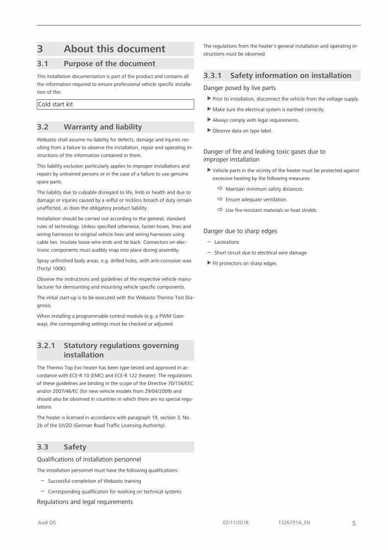
3 About this document3.1 Purpose of the document
This installation documentation is part of the product and contains allthe information required to ensure professional vehicle specific installa-tion of the:
Cold start kit
3.2 Warranty and liability
Webasto shall assume no liability for defects, damage and injuries res-ulting from a failure to observe the installation, repair and operating in-structions of the information contained in them.
This liability exclusion particularly applies to improper installations andrepairs by untrained persons or in the case of a failure to use genuinespare parts.
The liability due to culpable disregard to life, limb or health and due todamage or injuries caused by a wilful or reckless breach of duty remainunaffected, as does the obligatory product liability.
Installation should be carried out according to the general, standardrules of technology. Unless specified otherwise, fasten hoses, lines andwiring harnesses to original vehicle lines and wiring harnesses usingcable ties. Insulate loose wire ends and tie back. Connectors on elec-tronic components must audibly snap into place during assembly.
Spray unfinished body areas, e.g. drilled holes, with anti-corrosion wax(Tectyl 100K).
Observe the instructions and guidelines of the respective vehicle manu-facturer for demounting and mounting vehicle specific components.
The initial start-up is to be executed with the Webasto Thermo Test Dia-gnosis.
When installing a programmable control module (e.g. a PWM Gate-way), the corresponding settings must be checked or adjusted.
3.2.1 Statutory regulations governinginstallation
The Thermo Top Evo heater has been type-tested and approved in ac-cordance with ECE-R 10 (EMC) and ECE-R 122 (heater). The regulationsof these guidelines are binding in the scope of the Directive 70/156/EECand/or 2007/46/EC (for new vehicle models from 29/04/2009) andshould also be observed in countries in which there are no special regu-lations.
The heater is licensed in accordance with paragraph 19, section 3, No.2b of the StVZO (German Road Traffic Licensing Authority).
3.3 Safety
Qualifications of installation personnel
The installation personnel must have the following qualifications:
– Successful completion of Webasto training
– Corresponding qualification for working on technical systems
Regulations and legal requirements
The regulations from the heater's general installation and operating in-structions must be observed.
3.3.1 Safety information on installation
Danger posed by live parts
u Prior to installation, disconnect the vehicle from the voltage supply.
u Make sure the electrical system is earthed correctly.
u Always comply with legal requirements.
u Observe data on type label.
Danger of fire and leaking toxic gases due toimproper installation
u Vehicle parts in the vicinity of the heater must be protected againstexcessive heating by the following measures:
ð Maintain minimum safety distances.
ð Ensure adequate ventilation.
ð Use fire-resistant materials or heat shields.
Danger due to sharp edges
– Lacerations
– Short circuit due to electrical wire damage
u Fit protectors on sharp edges.

6 1326791A_EN 02/11/2018 Audi Q5
3.4 Using this document
Before installing and operating the heater, read this installation docu-mentation, the installation instructions of the heater, the operating in-structions and supplementary sheets provided.
3.4.1 Explanatory Notes on theDocument
There is an identification mark near the respective work step to allowyou to quickly allocate the other applicable documents to the Webastocomponents to be installed:
Generally valid Webasto documentation
Vehicle-specific installation documentation FK
Webasto Comfort A/C control FH
Webasto Standard A/C control FG
Tank extracting device (e.g. FuelFix) FF
Exhaust end fastener (EFIX) FE
Combustion air intake silencer FL
Spacer bracket (ASH) FS
3.4.2 Use of symbols
DANGERType and source of the risk
Consequences: Failure to follow the instructions can resultin death
u Actions to protect yourself against risks.
WARNINGType and source of the risk
Consequences: Failure to follow the instructions can leadto serious or even fatal injuries
u Actions to protect yourself against risks.
CAUTIONType and source of the risk
Consequences: Failure to follow the instructions can leadto minor injuries
u Actions to protect yourself against risks.
Type and source of the risk
Consequences: Failure to follow the instructions can leadto material damage
u Actions to protect yourself against risks.
Reference to the vehicle manufacturer's specific docu-ments.
a note on a special technical feature
3.4.3 Work step identification marks
The ongoing work step is indicated on the outside top corner of thepage:
Mechanicalsystem
Electrical Sys-tem
High-voltage Coolant
Combustionair
Fuel Exhaust gas Software
3.4.4 Orientation aid
The arrow indicates the position on the vehicle and the viewing angle
3.4.5 Use of highlighting
Highlight Explanation
Necessary action
ð Result of an action
A121 a1 Position numbers for the image descriptions
/ Position numbers for the image descriptionsfor electrical wires and wiring harnessesand coolant hose sections
Audi Q5 02/11/2018 1326791A_EN 7
4 Technical InformationDimension specifications
– All dimensions specified in mm
Tightening torque specifications– Tighten bolt connections in accordance with manufacturer's instructions or in accordance with state-of-the-art-
technology
Necessary special tools– Automatic wire stripper 0.2 - 6 mm²
– Crimping pliers for tab connector 0.14 – 6 mm²
– Crimping pliers for cable lugs 0.5 – 10 mm²
– Crimping pliers for connector 0.25 – 6 mm²
– Torque wrench for 2.0 - 10 Nm
– Webasto Thermo Test Diagnosis with current software

5 Preparing measures5.1 Vehicle preparation
Further information can be found in the vehicle manufacturer's technical documentation.
u Disconnect the battery
u Remove the coolant reservoir cover
u Remove the washer reservoir filler point
u Remove the engine control unit cover
u Pull out the engine control unit
u Remove the side instrument panel trim on the left
u Detach the upper instrument panel trim of the steering wheel
u Remove the lower instrument panel trim (central electrical box cover in passenger compartment) on the driver'sside
8 1326791A_EN 02/11/2018 Audi Q5

Audi Q5 02/11/2018 1326791A_EN 9
6 Installation Overview
CLR
DP
MCC
SH2
UPHG
RTD A B
Fig. 1
Legend to installation overview
Abbreviation Component
CLR CLR module
RTD Temperature sensor
A/B Adapter connector

7 Wiring diagram
31
Audi
br4²
rt0,5²
sw0,5²
CLR
or0,5²
ws0,5²
rt/ws0,75²
MSG
8
br/grX10A
B
25
24
26
27
RTD
30
G
br/gr
Webasto
HG
F2 F1
15
CAN LCAN H
6OBD
14
15
1
or/rt0,5²
or/br0,5²
sw/bl0,5²
sw/bl0,5²
21
Fig. 2
Legend to wiring diagram
Vehicle components Symbols
Abbreviation Component Abbreviation Designation
MSG Engine control unit X Cutting point
G 105-pin connector of MSG
OBD ON-Board Diagnosis
10 1326791A_EN 02/11/2018 Audi Q5
Audi Q5 02/11/2018 1326791A_EN 11
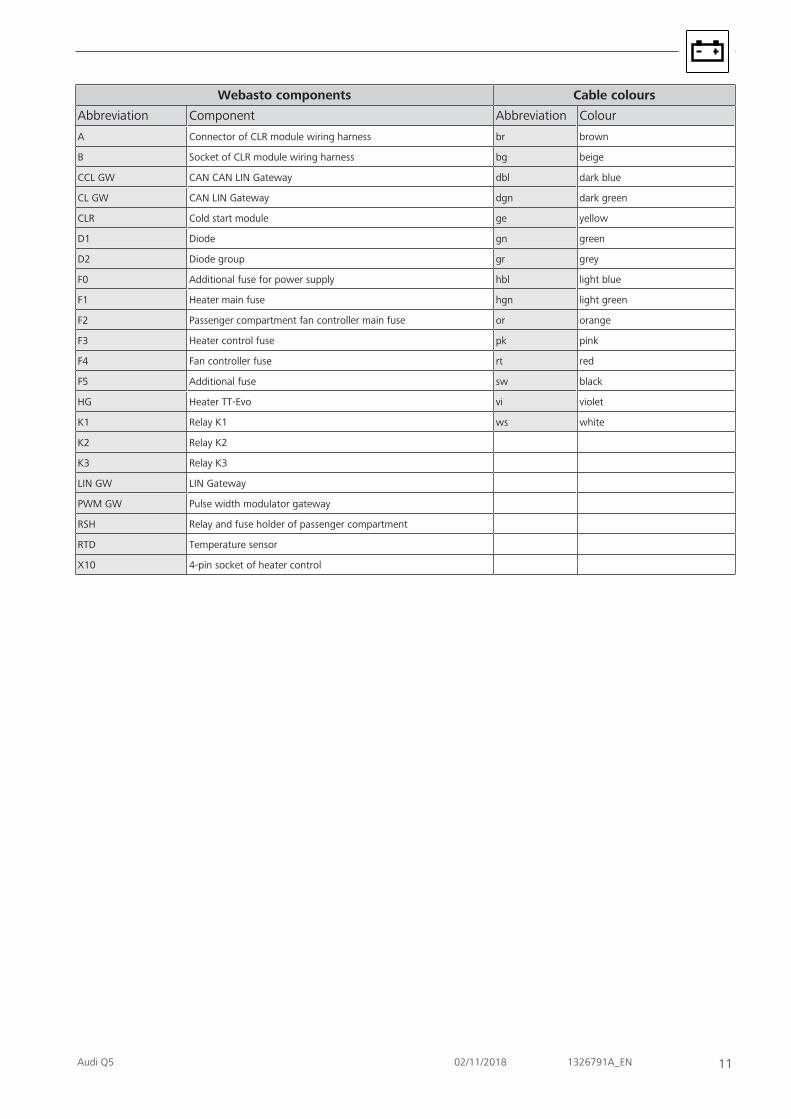
Webasto components Cable colours
Abbreviation Component Abbreviation Colour
A Connector of CLR module wiring harness br brown
B Socket of CLR module wiring harness bg beige
CCL GW CAN CAN LIN Gateway dbl dark blue
CL GW CAN LIN Gateway dgn dark green
CLR Cold start module ge yellow
D1 Diode gn green
D2 Diode group gr grey
F0 Additional fuse for power supply hbl light blue
F1 Heater main fuse hgn light green
F2 Passenger compartment fan controller main fuse or orange
F3 Heater control fuse pk pink
F4 Fan controller fuse rt red
F5 Additional fuse sw black
HG Heater TT-Evo vi violet
K1 Relay K1 ws white
K2 Relay K2
K3 Relay K3
LIN GW LIN Gateway
PWM GW Pulse width modulator gateway
RSH Relay and fuse holder of passenger compartment
RTD Temperature sensor
X10 4-pin socket of heater control

8 Electrical system8.1 Electrical system preparation
Assigning wires
sw0,5²rt
0,5²
24
25
Fig. 3
Red (rt) wire of cold start wiring harness
Black (sw) wire of cold start wiring harness
Premounting CLR module socket1
Fig. 4
1 M5x16 bolt, large diameter washer, CLR modulesocket, perforated bracket, large diameterwasher, nut
12 1326791A_EN 02/11/2018 Audi Q5

Audi Q5 02/11/2018 1326791A_EN 13
Preparing CLR module
Produce all following electrical connections as shown in the system wiring diagram.
u Detach black (sw) wire from terminal A and insulate.
u Connect red (rt) wire and black (sw) wire .
CLR
C2.8
A6.3 H
2.8
156.3
X2.8
W6.3
306.3
L2.8
316.3
rt/ws0,75²
ws0,5²
or0,5²
sw0,5²
rt0,5²
sw0,5²
CLR
C2.8
A6.3 H
2.8
156.3
X2.8
W6.3
306.3
L2.8
316.3
rt/ws0,75²
ws0,5²
or0,5²
1. 2.3.
24
25
26
27
26
27
21
21
RTD
RTD
30 X
HL
15
A
W31
C
Fig. 5

8.2 Connection in passenger compartment
Mounting CLR module socket1
Fig. 6
1 M6x20 bolt, large diameter washer, premountedsocket, original vehicle threaded insert
Mounting CLR module
1
Fig. 7
u Route wires and as well as temperature sensorRTD to the engine compartment cable grommet.
u Route wires , and to the OBD socket outlet.
1 CLR module
14 1326791A_EN 02/11/2018 Audi Q5
Audi Q5 02/11/2018 1326791A_EN 15
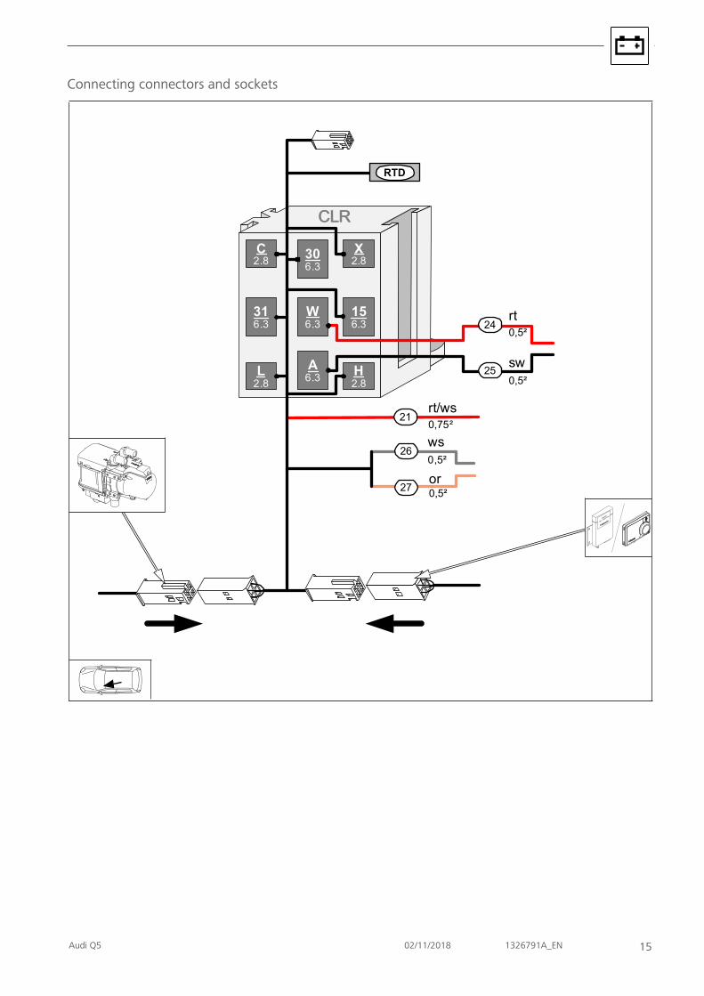
Connecting connectors and sockets
CLRCLR
C2.8
A6.3 H
2.8
156.3
X2.8
W6.3
306.3
L2.8
316.3
rt/ws0,75²
ws0,5²
or0,5²
rt0,5²
sw0,5²
24
25
21
26
27
RTD

Connection to OBD socket outlet
ws
1
9
6
14
or
0,5²
0,5²
27
26
1
1
2
3Fig. 8
Further information can be found in the vehiclemanufacturer's technical documentation.
u Remove OBD socket outlet from bracket.
u Crimp and shrink butt connector 1
2 Orange/red (or/rt) wire of OBD socket outlet/ pin6
3 Orange/brown (or/br) wire of OBD socket outlet/pin 14White (ws) wire of CLR module/ H cold start wir-ing harnessOrange (or) wire of CLR module/ L cold start wir-ing harness
1
9
6
14
rt/ws0,5²
21
13 2Fig. 9
u Crimp and shrink butt connector 2
1 Black/blue (sw/bl) wire of OBD socket outlet/ pin1
3 Black/blue (sw/bl) wire of terminal 15Red/white (rt/ws) wire of CLR module/ 15 coldstart wiring harness
8.3 Connection in engine compartment
View of engine control unit1 2
Fig. 10
u Pull out control unit 2 , the passenger compartmentcable grommet is located underneath.
u Route wires and as well as temperature sensorRTD through the cable grommet into the engine com-partment.
1 105-pin connector G of engine control unit
16 1326791A_EN 02/11/2018 Audi Q5

Audi Q5 02/11/2018 1326791A_EN 17
Fastening temperature sensor RTD
Fig. 11
u Fasten temperature sensor using cable ties.
8.4 Connection to engine control unit
View of engine control unit connector G, contact side1
Fig. 12
1 Engine control unit connector G, pin 8
View of engine control unit connector G, wiring side
1Fig. 13
1 Brown/grey (br/gr) wire of engine control unitconnector G, pin 8

Connection to engine control unit
13
2425
1
2
Fig. 14
u Remove the upper cover from connector Gand detach part of the wiring harness wrap-ping. Insulate and reinstall after completion.
u Crimp and shrink the butt connector.
1 Brown/grey (br/gr) wire of 105-pin engine con-trol unit connector G/ pin 8
2 Brown/grey (br/gr) wireRed (rt) wire of CLR module/W from cold startwiring harnessBlack (sw) wire of CLR module/A from cold startwiring harness
18 1326791A_EN 02/11/2018 Audi Q5

Audi Q5 02/11/2018 1326791A_EN 19
9 Final work
u Final work is not carried out until the installation of the heater in the vehicle has been com-pleted
u Check all electrical connections for firm seating
u Insulate and tie back loose lines

These are the original instructions. The German language is binding.You can request your language if it is missing. The telephone number of each country can be found in the Webasto service centreleaflet or the website of the respective Webasto representative of your country.
Webasto Thermo & Comfort SEPostfach 141082199 GilchingGermany
Company address:Friedrichshafener Str. 982205 GilchingGermany
Technical Extranet: https://dealers.webasto.com
Only within GermanyTel: 0395 5592 444E-mail: [email protected]
Iden
t No.
132
6791
A_E
N •
11/
18 •
Err
ors
and
omis
sion
s ex
cept
ed •
© W
ebas
to T
herm
o &
Com
fort
SE
• 20
18
WWW.WEBASTO.COM
20 Audi Q5