Se-modified Ru nanoparticles as ORR catalysts:: Part 2: Evaluation for use as DMFC cathodes
Upload
khangminh22Category
view
0download
0
RULES FOR CLASSIFICATION
Ships
Edition July 2021
Part 2 Materials and welding
Chapter 2 Metallic materials
The content of this service document is the subject of intellectual property rights reserved by DNV AS (“DNV”). The useraccepts that it is prohibited by anyone else but DNV and/or its licensees to offer and/or perform classification, certificationand/or verification services, including the issuance of certificates and/or declarations of conformity, wholly or partly, on thebasis of and/or pursuant to this document whether free of charge or chargeable, without DNV’s prior written consent. DNVis not responsible for the consequences arising from any use of this document by others.
The PDF electronic version of this document available at the DNV website dnv.com is the official version. If thereare any inconsistencies between the PDF version and any other available version, the PDF version shall prevail.
DNV AS

FOREWORD
DNV rules for classification contain procedural and technical requirements related to obtaining andretaining a class certificate. The rules represent all requirements adopted by the Society as basisfor classification.
© DNV AS July 2021
Any comments may be sent by e-mail to [email protected]
This service document has been prepared based on available knowledge, technology and/or information at the time of issuance of thisdocument. The use of this document by other parties than DNV is at the user's sole risk. Unless otherwise stated in an applicable contract,or following from mandatory law, the liability of DNV AS, its parent companies and subsidiaries as well as their officers, directors andemployees (“DNV”) for proved loss or damage arising from or in connection with any act or omission of DNV, whether in contract or in tort(including negligence), shall be limited to direct losses and under any circumstance be limited to 300,000 USD.

CHANGES – CURRENT
This document supersedes the July 2020 edition of DNVGL-RU-SHIP Pt.2 Ch.2.The numbering and/or title of items containing changes is highlighted in red.
Changes July 2021, entering into force 1 January 2022
Topic Reference Description
Definition of 'full anneal' Sec.1 [2] Added the definition of 'full anneal' in Table 1.
Tolerances for sections -manufacturer's conformancestandards
Sec.2 [2.11.5] Added that manufacturer's conformance standards may beaccepted subject to agreement with the Society.
CTOD verified steel grades Sec.2 [2.13.1],Sec.2 [8.2]
Added that for steel grades where CTOD properties are verifiedthe suffix COD shall be included.
A table was added with tolerances for the individual chemicalelements. The previous guidance note for the ranges ofelements is made mandatory.
NV 47 grades and gradeswith BCA properties: chemicalcomposition and Ceq
Sec.2 [4.2],Sec.2 [5.3]
Chemical composition amended as per IACS UR W31.
BCA steel grades: chemicalcomposition
Sec.2 [7.2] The previous guidance note for the ranges of elements is mademandatory.
Requirements for weldedhollow sections
Sec.2 [11] Acceptance criteria added for welding and NDT.
Impact test requirements forlow temperature steels
Sec.3 [1.11.1]Sec.5 [1.9.6]
Specified a lower limit of 3 mm on material thickness thatwould require to be tested using Charpy V-notch test. Thisthickness could encompass a test specimen with thickness 2.5mm as defined with dimensions and acceptance criteria in thereferred standard.
Steel plates for lowtemperature application:grades as per ASTM A645 andA353
Sec.3 [3] Grades NV 5Ni/b, NV 5Ni/c and NV 9Ni/b are added, withspecification for chemical composition, heat treatment andmechanical properties. Previous grades VL 5Ni and VL 9Ni arerenamed towards NV 5Ni/a and NV 9Ni/a.
Grade 316 Ti / 1.4571 Sec.3 [4] Specification added for new grade NV 316 Ti for chemicalcomposition and mechanical properties.
Sampling for pressed parts incase of preheating
Sec.3 [5.2] Relevant sentence is deleted. New wording is added that thesampling practice shall be performed in accordance with anagreed procedure.
Ram tensile test for steel-aluminium transition joints
Sec.4 [3.4] Added that alternatively to the through thickness tensile testthe ram tensile test as per MIL-J-24445A may be applied.Appropriate requirement to be fulfilled is added.
Delivery condition of weldedaustenitic pipes
Sec.5 [3.4] Added that it shall be demonstrated during the manufacturerapproval testing that the welded state leads to satisfactorycharacteristics. Further, it was added that grades manufacturedaccording to other standards approved by Society shall besolution heat treated.
Part 2 Chapter 2 Changes - current
Rules for classification: Ships — DNV-RU-SHIP Pt.2 Ch.2. Edition July 2021 Page 3Metallic materials
DNV AS

Topic Reference Description
Forged steel grade NV F3.5Ni:min yield strength amendedfrom 275 MPa to 345 MPa
Sec.6 [7.4] Amended in Table 13: for grade NV F3.5Ni the minimumspecified yield strength is increased to 345 MPa (frompreviously 275 MPa).
Cast steel grade 'S' with morerepresentative test block
Sec.8 [1] Introducing special grade cast steel 'S' which indicateslarger test block dimensions; requirements are amended todifferentiate on the size of the test block
Update figure 'Shape ofindications'
Sec.8 Figure 1 Updated figure 'Shape of indications' for clarity and updatedterminology
IACS UR W27 cast steelpropellers
Sec.8 [4] Requirements added for mechanical testing, visual inspection,NDT and repair.
Identification of castings Sec.8 [4.8.1] Added required particulars to identify castings
Duplex steel castings: testtemperature
Sec.8 [7.4.1] Temperature amended for charpy testing from RT to -20°C;added that testing shall be performed at design temperature.
Cu1 and Cu2 alloys: portion ofalpha-structure
Sec.11 [1.2] Requirement added for stating of portion of alpha-structure.
IACS UR W24 cast copper alloypropellers
Sec.11 [3] Requirements added for mechanical testing, visual inspection,NDT and repair.
New section for further non-iron metals and alloys
Sec.13 Requirements added for material grades and manufacturingprocesses which are not covered by other rule sections forsampling, test scope and test results.
New section for additivemanufactured material
Sec.14 Requirements added for sampling, test scope and test results.
Rebranding to DNV All This document has been revised due to the rebranding of DNVGL to DNV. The following have been updated: the companyname, material and certificate designations, and references toother documents in the DNV portfolio. Some of the documentsreferred to may not yet have been rebranded. If so, please seethe relevant DNV GL document.
Editorial correctionsIn addition to the above stated changes, editorial corrections may have been made.
Part 2 Chapter 2 Changes - current
Rules for classification: Ships — DNV-RU-SHIP Pt.2 Ch.2. Edition July 2021 Page 4Metallic materials
DNV AS
CONTENTS
Changes – current.................................................................................................. 3
Section 1 General..................................................................................................191 Introduction.......................................................................................191.1 Scope............................................................................................ 191.2 Application..................................................................................... 191.3 Relation to other Society documents................................................. 19
2 References......................................................................................... 202.1 External references......................................................................... 202.2 Abbreviations, symbols and terminology............................................ 20
3 Procedural requirements................................................................... 223.1 Required compliance documentation..................................................223.2 Documentation requirements............................................................223.3 Survey, inspection and testing requirements...................................... 23
Section 2 Rolled steel for structural application................................................... 241 General.............................................................................................. 241.1 Scope............................................................................................ 24
2 Documentation and required compliance documentation...................252.1 Compliance documents.................................................................... 252.2 Documentation requirements............................................................262.3 Survey, inspection and testing requirements...................................... 262.4 Grading system.............................................................................. 272.5 Manufacture................................................................................... 272.6 Chemical composition......................................................................282.7 Condition of supply and heat treatment.............................................292.8 Test material and test specimens for mechanical testing...................... 302.9 Test units and number of tests.........................................................332.10 Mechanical properties.................................................................... 342.11 Inspection and tolerances.............................................................. 342.12 Repair..........................................................................................352.13 Identification................................................................................ 36
3 Normal strength steel........................................................................373.1 Scope............................................................................................ 373.2 Chemical composition......................................................................373.3 Condition of supply and heat treatment.............................................383.4 Mechanical properties...................................................................... 38
Part 2 Chapter 2 Contents
Rules for classification: Ships — DNV-RU-SHIP Pt.2 Ch.2. Edition July 2021 Page 5Metallic materials
DNV AS

4 High strength steel............................................................................394.1 Scope............................................................................................ 394.2 Chemical composition......................................................................404.3 Condition of supply and heat treatment.............................................414.4 Mechanical properties...................................................................... 41
5 Extra high strength steel...................................................................435.1 Scope............................................................................................ 435.2 Method of manufacture................................................................... 445.3 Chemical composition......................................................................445.4 Condition of supply and heat treatment.............................................475.5 Mechanical properties...................................................................... 48
6 Z-quality steels (plates with through thickness properties)...............516.1 Scope............................................................................................ 516.2 Chemical composition......................................................................526.3 Manufacture................................................................................... 526.4 Test material.................................................................................. 526.5 Mechanical testing.......................................................................... 536.6 Ultrasonic testing............................................................................53
7 BCA steels (steels with brittle crack arresting properties).................537.1 Scope............................................................................................ 537.2 Chemical composition......................................................................547.3 Manufacture and testing.................................................................. 547.4 Identification.................................................................................. 55
8 COD steels (steels with crack initiation resistance)...........................558.1 Scope............................................................................................ 558.2 Chemical composition......................................................................568.3 Manufacture................................................................................... 568.4 Identification.................................................................................. 57
9 Corrosion resistant steels for cargo oil tanks.................................... 579.1 Scope............................................................................................ 579.2 Chemical composition......................................................................579.3 Manufacture................................................................................... 589.4 Identification.................................................................................. 58
10 Steels with higher ductility..............................................................5810.1 Scope.......................................................................................... 5810.2 Chemical composition.................................................................... 5810.3 Manufacture................................................................................. 5810.4 Mechanical testing.........................................................................5910.5 Identification................................................................................ 60
Part 2 Chapter 2 Contents
Rules for classification: Ships — DNV-RU-SHIP Pt.2 Ch.2. Edition July 2021 Page 6Metallic materials
DNV AS

11 Cold formed, welded hollow sections...............................................6011.1 Scope.......................................................................................... 6011.2 Manufacture................................................................................. 6011.3 Chemical composition.................................................................... 6111.4 Mechanical testing.........................................................................6111.5 Inspection and tolerances.............................................................. 6211.6 Repair..........................................................................................6311.7 Identification................................................................................ 63
Section 3 Rolled steel for boilers, pressure vessels and special applications.........641 General.............................................................................................. 641.1 Scope............................................................................................ 641.2 Required compliance documentation..................................................641.3 Documentation requirements............................................................651.4 Survey, inspection and testing requirements...................................... 651.5 Manufacture................................................................................... 661.6 General for testing..........................................................................661.7 Test unit........................................................................................ 661.8 Chemical composition......................................................................661.9 Tensile testing at ambient temperature..............................................671.10 Tensile testing at elevated temperatures.......................................... 671.11 Impact testing.............................................................................. 671.12 Drop weight testing.......................................................................681.13 Testing of through thickness properties............................................681.14 Corrosion testing...........................................................................681.15 Inspections, dimensions and tolerances........................................... 681.16 Surface condition and rectification of defects.................................... 691.17 Identification and marking............................................................. 69
2 Steel for boilers and pressure vessels............................................... 692.1 Steel grades...................................................................................692.2 Chemical composition......................................................................702.3 Condition of supply and heat treatment.............................................702.4 Mechanical properties...................................................................... 71
3 Steel for low temperature service..................................................... 783.1 Scope............................................................................................ 783.2 Steel grades...................................................................................783.3 Chemical composition......................................................................793.4 Condition of supply and heat treatment.............................................813.5 Mechanical properties...................................................................... 82
Part 2 Chapter 2 Contents
Rules for classification: Ships — DNV-RU-SHIP Pt.2 Ch.2. Edition July 2021 Page 7Metallic materials
DNV AS

3.6 Non-destructive testing....................................................................864 Stainless steel....................................................................................864.1 Scope............................................................................................ 864.2 Steel grades...................................................................................864.3 Chemical composition......................................................................864.4 Heat treatment...............................................................................874.5 Mechanical properties...................................................................... 874.6 Corrosion tests............................................................................... 88
5 Pressed parts.....................................................................................885.1 Scope............................................................................................ 885.2 Manufacture................................................................................... 895.3 Mechanical properties...................................................................... 925.4 Inspection...................................................................................... 93
Section 4 Clad products........................................................................................ 951 General requirements........................................................................ 951.1 Scope............................................................................................ 951.2 Required compliance documentation..................................................951.3 Documentation requirements............................................................961.4 Survey, inspection and testing requirements...................................... 961.5 Manufacture................................................................................... 971.6 Chemical composition......................................................................971.7 Condition of supply......................................................................... 971.8 Mechanical testing.......................................................................... 971.9 Inspections, dimensions and tolerances............................................. 971.10 Repair..........................................................................................981.11 Identification................................................................................ 98
2 Clad steel plates................................................................................ 982.1 Scope............................................................................................ 982.2 Manufacture................................................................................... 992.3 Chemical composition......................................................................992.4 Mechanical and corrosion testing...................................................... 992.5 Inspection.................................................................................... 1002.6 Repair..........................................................................................101
3 Steel-aluminium transition joints.....................................................1013.1 Scope.......................................................................................... 1013.2 Manufacture................................................................................. 1013.3 Chemical composition.................................................................... 1013.4 Mechanical testing.........................................................................102
Part 2 Chapter 2 Contents
Rules for classification: Ships — DNV-RU-SHIP Pt.2 Ch.2. Edition July 2021 Page 8Metallic materials
DNV AS
3.5 Inspection.................................................................................... 103
Section 5 Steel pipes and fittings....................................................................... 1051 General requirements for pipes....................................................... 1051.1 Scope.......................................................................................... 1051.2 Required compliance documentation................................................ 1051.3 Documentation requirements.......................................................... 1051.4 Survey, inspection and testing requirements.....................................1061.5 Materials...................................................................................... 1071.6 Manufacture................................................................................. 1071.7 Chemical composition.................................................................... 1071.8 Condition of supply....................................................................... 1081.9 Mechanical testing.........................................................................1081.10 Leak tightness testing..................................................................1091.11 Inspection.................................................................................. 1091.12 Repair........................................................................................ 1091.13 Identification...............................................................................110
2 Pipes for pressure systems..............................................................1102.1 Scope.......................................................................................... 1102.2 Materials...................................................................................... 1102.3 Manufacture................................................................................. 1102.4 Mechanical testing.........................................................................110
3 Austenitic and ferritic-austenitic steel pipes....................................1113.1 Scope.......................................................................................... 1113.2 Materials...................................................................................... 1113.3 Manufacture................................................................................. 1113.4 Condition of supply....................................................................... 1113.5 Mechanical testing.........................................................................1113.6 Corrosion testing...........................................................................112
4 Pipes for low-temperature service...................................................1124.1 Scope.......................................................................................... 1124.2 Materials...................................................................................... 1124.3 Manufacture................................................................................. 1124.4 Mechanical testing.........................................................................112
5 Boiler and superheater tubes.......................................................... 1135.1 Scope.......................................................................................... 1135.2 Materials...................................................................................... 1135.3 Manufacture................................................................................. 113
6 Piping fittings.................................................................................. 114
Part 2 Chapter 2 Contents
Rules for classification: Ships — DNV-RU-SHIP Pt.2 Ch.2. Edition July 2021 Page 9Metallic materials
DNV AS
6.1 Scope.......................................................................................... 1146.2 Materials...................................................................................... 1146.3 Manufacture................................................................................. 1146.4 Chemical composition.................................................................... 1156.5 Condition of supply....................................................................... 1156.6 Mechanical testing.........................................................................1156.7 Corrosion testing...........................................................................1166.8 Inspection.................................................................................... 1166.9 Identification................................................................................ 117
Section 6 Steel forgings...................................................................................... 1181 General requirements...................................................................... 1181.1 Scope.......................................................................................... 1181.2 Required compliance documentation................................................ 1181.3 Documentation requirements.......................................................... 1191.4 Survey, inspection and testing requirements.....................................1191.5 Grading system.............................................................................1201.6 Manufacture................................................................................. 1211.7 Chemical composition.................................................................... 1231.8 Condition of supply and heat treatment........................................... 1231.9 Test material and test specimens for mechanical testing.....................1241.10 Test units and number of tests..................................................... 1251.11 Mechanical properties.................................................................. 1251.12 Inspection.................................................................................. 1261.13 Repair........................................................................................ 1271.14 Identification...............................................................................127
2 Forgings for hull structures and equipment.....................................1282.1 Scope.......................................................................................... 1282.2 Chemical composition.................................................................... 1282.3 Condition of supply and heat treatment........................................... 1282.4 Mechanical testing.........................................................................1292.5 Inspection.................................................................................... 130
3 Forgings for shafting and machinery............................................... 1303.1 Scope.......................................................................................... 1303.2 Chemical composition.................................................................... 1303.3 Heat treatment............................................................................. 1313.4 Mechanical testing.........................................................................1313.5 Inspection.................................................................................... 132
4 Forgings for crankshafts..................................................................133
Part 2 Chapter 2 Contents
Rules for classification: Ships — DNV-RU-SHIP Pt.2 Ch.2. Edition July 2021 Page 10Metallic materials
DNV AS

4.1 Scope.......................................................................................... 1334.2 Chemical composition.................................................................... 1334.3 Heat treatment............................................................................. 1344.4 Mechanical testing.........................................................................1344.5 Inspection.................................................................................... 134
5 Forgings for gearing........................................................................ 1355.1 Scope.......................................................................................... 1355.2 Chemical composition.................................................................... 1355.3 Heat treatment............................................................................. 1355.4 Mechanical testing of forgings not intended for carburising................. 1365.5 Testing of forgings intended for carburising...................................... 1385.6 Inspection.................................................................................... 139
6 Forgings for boilers, pressure vessels and piping systems...............1396.1 Scope.......................................................................................... 1396.2 Chemical composition.................................................................... 1396.3 Heat treatment............................................................................. 1406.4 Mechanical properties.................................................................... 1406.5 Inspection.................................................................................... 1416.6 Pressure testing............................................................................ 141
7 Ferritic steel forgings for low temperature service.......................... 1417.1 Scope.......................................................................................... 1417.2 Chemical composition.................................................................... 1417.3 Heat treatment............................................................................. 1427.4 Mechanical properties.................................................................... 1427.5 Inspection.................................................................................... 1437.6 Pressure testing............................................................................ 143
8 Stainless steel forgings................................................................... 1438.1 Scope.......................................................................................... 1438.2 Manufacture................................................................................. 1448.3 Mechanical properties.................................................................... 1448.4 Inspection.................................................................................... 144
9 Bolts and nuts................................................................................. 1449.1 Scope.......................................................................................... 1449.2 Materials...................................................................................... 1459.3 Manufacture................................................................................. 1469.4 Chemical composition.................................................................... 1469.5 Test units, products to be tested, tests scope................................... 1469.6 Mechanical properties.................................................................... 1499.7 Inspection.................................................................................... 149
Part 2 Chapter 2 Contents
Rules for classification: Ships — DNV-RU-SHIP Pt.2 Ch.2. Edition July 2021 Page 11Metallic materials
DNV AS

9.8 Identification................................................................................ 149
Section 7 Bars for chain cables...........................................................................1511 General............................................................................................ 1511.1 Scope.......................................................................................... 1511.2 Required compliance documentation................................................ 1511.3 Documentation requirements.......................................................... 1511.4 Survey, inspection and testing requirements.....................................1511.5 Manufacture................................................................................. 1521.6 Condition of supply....................................................................... 152
2 Testing............................................................................................. 1522.1 Chemical composition.................................................................... 1522.2 Test units, test material and number of tests....................................1522.3 Mechanical properties.................................................................... 152
3 Inspection, tolerances and repair.................................................... 1543.1 Inspection and tolerances.............................................................. 1543.2 Repair..........................................................................................154
4 Identification................................................................................... 1544.1 Marking........................................................................................154
Section 8 Steel castings...................................................................................... 1551 General requirements...................................................................... 1551.1 Scope.......................................................................................... 1551.2 Required compliance documentation................................................ 1551.3 Documentation requirements.......................................................... 1561.4 Survey, inspection and testing requirements.....................................1571.5 Grading system.............................................................................1581.6 Manufacture................................................................................. 1591.7 Chemical composition.................................................................... 1591.8 Heat treatment............................................................................. 1601.9 Test blocks and test specimens for mechanical testing....................... 1601.10 Test units and number of tests..................................................... 1611.11 Mechanical properties.................................................................. 1611.12 Inspection.................................................................................. 1611.13 Repair........................................................................................ 1641.14 Identification...............................................................................166
2 Castings for hull structures and equipment..................................... 1662.1 Scope.......................................................................................... 1662.2 Chemical composition.................................................................... 166
Part 2 Chapter 2 Contents
Rules for classification: Ships — DNV-RU-SHIP Pt.2 Ch.2. Edition July 2021 Page 12Metallic materials
DNV AS

2.3 Heat treatment............................................................................. 1672.4 Mechanical properties.................................................................... 1672.5 Inspection.................................................................................... 168
3 Castings for machinery.................................................................... 1683.1 Scope.......................................................................................... 1683.2 Chemical composition.................................................................... 1683.3 Heat treatment............................................................................. 1693.4 Mechanical properties.................................................................... 1693.5 Inspection.................................................................................... 170
4 Castings for propellers.....................................................................1704.1 Scope.......................................................................................... 1704.2 Manufacture................................................................................. 1704.3 Chemical composition.................................................................... 1714.4 Heat treatment............................................................................. 1714.5 Mechanical testing.........................................................................1714.6 Inspection.................................................................................... 1714.7 Repair..........................................................................................1734.8 Identification................................................................................ 1744.9 Welding procedure qualification test................................................ 174
5 Castings for boilers, pressure vessels and piping systems............... 1795.1 Scope.......................................................................................... 1795.2 Chemical composition.................................................................... 1795.3 Heat treatment............................................................................. 1795.4 Mechanical properties.................................................................... 1805.5 Inspection.................................................................................... 1805.6 Pressure testing............................................................................ 180
6 Ferritic steel castings for low temperature service.......................... 1806.1 Scope.......................................................................................... 1806.2 Chemical composition.................................................................... 1816.3 Heat treatment............................................................................. 1816.4 Mechanical properties.................................................................... 1816.5 Inspection.................................................................................... 1826.6 Pressure testing............................................................................ 182
7 Stainless steel castings................................................................... 1827.1 Scope.......................................................................................... 1827.2 Chemical composition.................................................................... 1827.3 Heat treatment............................................................................. 1837.4 Mechanical properties.................................................................... 1837.5 Corrosion tests............................................................................. 184
Part 2 Chapter 2 Contents
Rules for classification: Ships — DNV-RU-SHIP Pt.2 Ch.2. Edition July 2021 Page 13Metallic materials
DNV AS

7.6 Inspection.................................................................................... 1847.7 Pressure testing............................................................................ 184
Section 9 Iron castings....................................................................................... 1851 General............................................................................................ 1851.1 Scope.......................................................................................... 1851.2 Required compliance documentation................................................ 1851.3 Documentation requirements.......................................................... 1851.4 Survey, inspection and testing requirements.....................................1861.5 Quality of castings........................................................................ 1861.6 Manufacture................................................................................. 1861.7 Chemical composition.................................................................... 1871.8 Condition of supply and heat treatment........................................... 1871.9 Testing.........................................................................................1871.10 Visual and non-destructive examination......................................... 1871.11 Repair of defects.........................................................................188
2 Nodular cast iron............................................................................. 1882.1 Scope.......................................................................................... 1882.2 Test material................................................................................ 1882.3 Mechanical properties.................................................................... 1912.4 Metallographic examination............................................................ 192
3 Grey cast iron.................................................................................. 1923.1 Scope.......................................................................................... 1923.2 Test material................................................................................ 1923.3 Mechanical properties.................................................................... 194
Section 10 Aluminium alloys............................................................................... 1951 Wrought aluminium alloys...............................................................1951.1 Scope.......................................................................................... 1951.2 Required compliance documentation................................................ 1951.3 Documentation requirements.......................................................... 1951.4 Survey, inspection and testing requirements.....................................1961.5 Materials...................................................................................... 1961.6 Manufacture................................................................................. 1971.7 Chemical composition.................................................................... 1971.8 Temper conditions......................................................................... 1981.9 Mechanical testing.........................................................................1981.10 Press weld testing of closed sections............................................. 2011.11 Corrosion testing.........................................................................202
Part 2 Chapter 2 Contents
Rules for classification: Ships — DNV-RU-SHIP Pt.2 Ch.2. Edition July 2021 Page 14Metallic materials
DNV AS

1.12 Inspections, dimensions and tolerances..........................................2031.13 Repair........................................................................................ 2031.14 Identification...............................................................................203
2 Aluminium casting alloys.................................................................2042.1 Scope.......................................................................................... 2042.2 Required compliance documentation................................................ 2052.3 Documentation requirements.......................................................... 2052.4 Survey, inspection and testing requirements.....................................2052.5 Manufacture................................................................................. 2062.6 Chemical composition.................................................................... 2062.7 Temper conditions......................................................................... 2062.8 Mechanical testing.........................................................................2062.9 Inspections, dimensions and tolerances........................................... 2062.10 Identification...............................................................................206
Section 11 Copper alloy castings........................................................................ 2071 General requirements...................................................................... 2071.1 Scope.......................................................................................... 2071.2 Required compliance documentation................................................ 2071.3 Documentation requirements.......................................................... 2071.4 Survey, inspection and testing requirements.....................................2081.5 Grading system.............................................................................2091.6 Manufacture................................................................................. 2091.7 Chemical composition.................................................................... 2091.8 Heat treatment............................................................................. 2091.9 Test blocks and test specimens for mechanical testing....................... 2101.10 Test units and number of tests..................................................... 2111.11 Mechanical properties.................................................................. 2111.12 Inspection.................................................................................. 2111.13 Repair........................................................................................ 2121.14 Identification...............................................................................212
2 Castings for valves, fittings and general application........................2122.1 Scope.......................................................................................... 2122.2 Chemical composition.................................................................... 2132.3 Condition of supply and heat treatment........................................... 2132.4 Mechanical properties.................................................................... 2132.5 Inspection.................................................................................... 2142.6 Repair..........................................................................................214
3 Castings for propellers.....................................................................215
Part 2 Chapter 2 Contents
Rules for classification: Ships — DNV-RU-SHIP Pt.2 Ch.2. Edition July 2021 Page 15Metallic materials
DNV AS

3.1 Scope.......................................................................................... 2153.2 Manufacture................................................................................. 2153.3 Chemical composition.................................................................... 2153.4 Condition of supply....................................................................... 2163.5 Mechanical and metallographic testing............................................. 2163.6 Inspection.................................................................................... 2163.7 Repair..........................................................................................2173.8 Straightening................................................................................ 2183.9 Identification................................................................................ 2193.10 Welding procedure qualification..................................................... 219
Section 12 Non-ferrous tubes............................................................................. 2201 General requirements...................................................................... 2201.1 Scope.......................................................................................... 2201.2 Required compliance documentation................................................ 2201.3 Documentation requirements.......................................................... 2201.4 Survey, inspection and testing requirements.....................................221
2 Copper and copper alloy tubes........................................................ 2212.1 Scope.......................................................................................... 2212.2 Materials...................................................................................... 2212.3 Chemical composition.................................................................... 2222.4 Condition of supply and heat treatment........................................... 2222.5 Mechanical testing.........................................................................2222.6 Inspection.................................................................................... 2232.7 Repair..........................................................................................2232.8 Identification................................................................................ 223
3 Copper and copper alloy fittings......................................................2233.1 Scope.......................................................................................... 2233.2 Manufacture................................................................................. 2233.3 Testing and inspection................................................................... 2233.4 Identification................................................................................ 224
4 Titanium and titanium alloy tubes and fittings................................ 2244.1 Scope.......................................................................................... 2244.2 Manufacture................................................................................. 224
Section 13 Other metallic materials and manufacturing methods....................... 2251 General requirements...................................................................... 2251.1 Scope.......................................................................................... 2251.2 Required compliance documentation................................................ 225
Part 2 Chapter 2 Contents
Rules for classification: Ships — DNV-RU-SHIP Pt.2 Ch.2. Edition July 2021 Page 16Metallic materials
DNV AS

1.3 Documentation requirements.......................................................... 2261.4 Survey, inspection and testing requirements.....................................2261.5 Grading system.............................................................................2261.6 Manufacture................................................................................. 2271.7 Chemical composition.................................................................... 2271.8 Condition of supply and heat treatment........................................... 2271.9 Test material and test specimens for mechanical testing.....................2271.10 Test units and number of tests..................................................... 2281.11 Mechanical properties.................................................................. 2281.12 Inspection and tolerances.............................................................2281.13 Repair........................................................................................ 2281.14 Identification...............................................................................229
2 Material grades specified to a recognized standard......................... 2292.1 Scope.......................................................................................... 2292.2 Initial qualification and establishment of the manufacturerspecification....................................................................................... 2292.3 Manufacturer specification.............................................................. 2302.4 Production testing and certification..................................................231
3 New material grades and new manufacturing methods................... 2313.1 Scope.......................................................................................... 2313.2 Risk evaluation, manufacturer specification and qualification testing.....231
Section 14 Additively manufactured metallic materials.......................................2321 General requirements...................................................................... 2321.1 Scope.......................................................................................... 2321.2 Required compliance documents..................................................... 2321.3 Documentation requirements.......................................................... 2331.4 Survey, inspection and testing requirements.....................................2341.5 Grading system.............................................................................2351.6 Manufacture................................................................................. 2361.7 Chemical composition.................................................................... 2361.8 Condition of supply and heat treatment........................................... 2371.9 Test material and test specimens for mechanical testing.....................2371.10 Test units and number of tests..................................................... 2381.11 Mechanical properties.................................................................. 2381.12 Inspection and tolerances.............................................................2391.13 Repair........................................................................................ 2391.14 Identification...............................................................................239
Section 15 References.........................................................................................241
Part 2 Chapter 2 Contents
Rules for classification: Ships — DNV-RU-SHIP Pt.2 Ch.2. Edition July 2021 Page 17Metallic materials
DNV AS

1 References....................................................................................... 241
Changes – historic.............................................................................................. 247
Part 2 Chapter 2 Contents
Rules for classification: Ships — DNV-RU-SHIP Pt.2 Ch.2. Edition July 2021 Page 18Metallic materials
DNV AS

SECTION 1 GENERAL
1 Introduction
1.1 Scope
1.1.1 The chapter specifies requirements for metallic materials used for construction of vessels and theirequipment with respect to:
— manufacture— inspection and tolerances— repair— identification and certification— condition of supply and heat treatment— test units, test material and test specimens— grading systems— chemical composition— mechanical properties— other test requirements, e.g. corrosion test, drop weight test, etc.
1.1.2 The requirements apply for assignment of class.
1.1.3 Upon agreement, the scope may be extended to other applications.
1.2 Application
1.2.1 The following materials/products are covered:
— rolled steels including rolled stainless steels— clad steel and steel-aluminium transition joints— pipes of steel, stainless steels, aluminium alloys, copper alloys and titanium alloys— forgings and castings of steel, iron, stainless steels, copper alloys and aluminium alloys.
1.3 Relation to other Society documents
1.3.1 General requirements for manufacture and fabrication of materials and components are given in Ch.1,and specific requirements related to welding and fabrication are given in Ch.4. Additional requirementsmay also be provided in each section of this chapter, and in Ch.4, as well as in other parts of the rules.Where specific or additional requirements are provided in other parts of the rules, the specific or additionalrequirements are prevailing.
Part 2 Chapter 2 Section 1
Rules for classification: Ships — DNV-RU-SHIP Pt.2 Ch.2. Edition July 2021 Page 19Metallic materials
DNV AS

2 References
2.1 External references
2.1.1 The external references referred in this chapter are listed in Sec.15. Unless otherwise agreed, thelatest version of the referred standards valid at the date of release for the current rules is applicable.
2.2 Abbreviations, symbols and terminology
2.2.1 General abbreviations and symbols are given in Ch.1 Sec.1 [2.3] and Ch.1 Sec.1 [2.4].
2.2.2 General definitions are given in Pt.1 Ch.1 Sec.1 [1.2] and Ch.1 Sec.1 [2.1]. Special terminology isgiven in Table 1.
Table 1 Terminology
Term Definition
Additivemanufacturing
process of joining materials to make objects from 3D model data, usually layer upon layer, asopposed to subtractive manufacturing methodologies
Aligned indication three or more MT or PT indications in a line, separated by 2 mm or less edge-to-edge
build job building of a part or a set of parts, from deposition of initial layer to the layer
build process layer-by-layer deposition which occurs during a build job, defined by means of essentialparameters
build processqualification
process leading to a qualified build process, including building, post processing, testing anddocumentation
build processqualification record
document containing information produced during build process qualification, including allessential parameters, log files and test results
directed energydeposition
additive manufacturing process in which focused thermal energy is used to fuse materials bymelting as they are being deposited
fully annealed process in which the steel is heated to just above the Ac3 temperature, with a soaking timesufficient to give a fully austenite structure, followed by slow cooling (e.g. furnace cooling),resulting in a microstructure that closely resembles the metal's phase diagram equilibrium state.Compared to other heat treatment conditions the fully annealed steel would typically presentrelatively low hardness, yield and ultimate tensile strength, and high ductility
HFW hollow section hollow long product, open at both ends, of circular, square or rectangular section, made bypressure welding in a continuous or non-continuous process, in which strip is formed cold into ahollow profile and the seam weld made by heating the adjacent edges through the resistance tothe passage of a high frequency current and pressing the edges together, see EN 10225
Killed steel steel fully deoxidized before casting by the addition of typically silicon, manganese andaluminium, giving virtually no gas evolution during solidification
Linear indication MT or PT indication in which the length is at least three times the width
Non-linear indication MT or PT indication of circular or elliptical shape with a length less than three times the width
Non-open indication MT or PT indication that is not visually detectable after removal of the magnetic particles or thatcannot be detected by the use of contrast dye penetrant
Part 2 Chapter 2 Section 1
Rules for classification: Ships — DNV-RU-SHIP Pt.2 Ch.2. Edition July 2021 Page 20Metallic materials
DNV AS

Term Definition
Open indication MT or PT indication visible after removal of the magnetic particles or that can be detected by theuse of contrast dye penetrant
Piece for testing of individual pieces of rolled products, a piece shall be regarded as the rolled productfrom a single slab or billet, or from a single ingot if this is rolled directly into plates, strip, sectionsor bars
powder bed fusion additive manufacturing process in which thermal energy selectively fuses regions of a powder bed
Relevant indication MT or PT indication that is caused by a condition or type of discontinuity that requires evaluation.Indications which have any dimension greater than 1.5 mm shall be considered relevant
SAWL hollow section tubular product having one or two longitudinal seams produced by submerged-arc welding
When two longitudinal seams apply, they shall be approximately 180° apart, see EN 10225
SAWH hollow section tubular product having one helical seam produced by submerged arc welding, see EN 10225
Semi-killed steel steel partly deoxidized before casting, giving some gas evolution in the melt during solidification
Solution heattreatment
process in which an alloy or metal is heated to a suitable temperature, is held at that temperaturelong enough to allow a certain constituent to enter into solid solution, and is then cooled rapidlyto hold that constituent in solution
Stabilizationannealing
process in which austenitic stainless steels that contain titanium or niobium are heated to atemperature below that of a full anneal in order to precipitate the maximum amount of carbon astitanium carbides or niobium carbides
submerged arcwelding (SAW)
process that welding process that produces melting and coalescence of metals by heating themwith an arc or arcs between a bare metal consumable electrode or electrodes and the workpiece,wherein the arc and molten metal are shielded by a blanket of granular flux, see EN 10225
Part 2 Chapter 2 Section 1
Rules for classification: Ships — DNV-RU-SHIP Pt.2 Ch.2. Edition July 2021 Page 21Metallic materials
DNV AS

3 Procedural requirements
3.1 Required compliance documentation
3.1.1 General compliance documentation requirements are given in Ch.1.Required compliance documents for materials relevant to application are given in Pt.3 to Pt.7, see also [1.3].Where applicable, additional specific compliance documentation requirements are given within each of thefollowing sections.
3.2 Documentation requirements
3.2.1 General documentation requirements are given in Ch.1. Additional product specific documentationrequirements are given in Table 2, and additional manufacturer specific documentation requirements aregiven in Table 3. Further specific documentation requirements are given in each section as relevant.
Table 2 Documentation requirements – products required to be certified
Object Documentation type Additional description Info 1)
C051 - Non-destructive testing (NDT)report
including testing after repair FI
Z250 - Procedure for repair by welding, when applicable.For content of procedure, M062 may beused as guidance
AP, L
Materials for structure andcomponents
M062 – Report from repair by welding each repair weld. FI
1) FI = for information, AP = for approval, L = by local station.
For full definition of abbreviations, see DNV-CG-0550 Sec.6
Table 3 Qualification documentation for manufacturer
Item Documentation type Additional description
M010 - Material specification, metals For NV material certification: shall be provided to thesurveyor prior to testing and survey, including anyconditions additional to the rule requirements.
M060 – Welding procedure (WPS) For materials and products joined or repaired bywelding. Approval by the Society's local station.
Z252 - Test procedures atmanufacturer
Manufacturer shall establish detailed procedures fortesting, retesting and non-destructive testing.
Materials and components
Z270 - Records Surface inspection and dimensions including shapeand straightness:
— the manufacturer shall maintain records ofinspections and dimensional measurements
— the records shall be presented to the surveyor onrequest.
Part 2 Chapter 2 Section 1
Rules for classification: Ships — DNV-RU-SHIP Pt.2 Ch.2. Edition July 2021 Page 22Metallic materials
DNV AS

Item Documentation type Additional description
Heat treatment:
— the manufacturer shall maintain records/logsof heat treatment identifying the furnace used,furnace charge, date, temperatures and time attemperatures
— the records shall be presented to the surveyor onrequest.
Investigation:
Where deviations from approved process occurs andthis could produce products of inferior quality.
(Root cause analysis and corrective action plan shallbe a part of their QA-QC procedures.)
Welders Z270 - Records Of welders certificates, all welders performingwelding shall be certified. See also Ch.4 Sec.3.Applicable for welding on materials and products forNV or W certification.
NDT personnel Z270 - Record Of NDT operators certificates, all NDT shall be carriedout by personnel qualified and certified to at leastlevel II by a recognized body for the applicable NDTmethod. See further requirement in Ch.4 Sec.7 [3].
Furnace Z262 - Report from test atmanufacturer
For calibration. For products subject to heattreatment, the furnace temperature uniformity shallbe calibrated according to a recognized standard(e.g. ASTM A991) at regular intervals and thecalibration report shall be provided to the surveyoron request.
Note that approval as heat treatment workshop maybe required, see Ch.1 Sec.2 [2].
3.2.2 For general requirements to documentation including definitions, see DNV-CG-0550.
3.3 Survey, inspection and testing requirements
3.3.1 General survey, inspection and testing requirements are given in Ch.1 Sec.1 [3.3] and Ch.1 Sec.2[3.2]. Specific requirements are given in the relevant sections of this chapter.
Part 2 Chapter 2 Section 1
Rules for classification: Ships — DNV-RU-SHIP Pt.2 Ch.2. Edition July 2021 Page 23Metallic materials
DNV AS
SECTION 2 ROLLED STEEL FOR STRUCTURAL APPLICATION
1 General
1.1 Scope
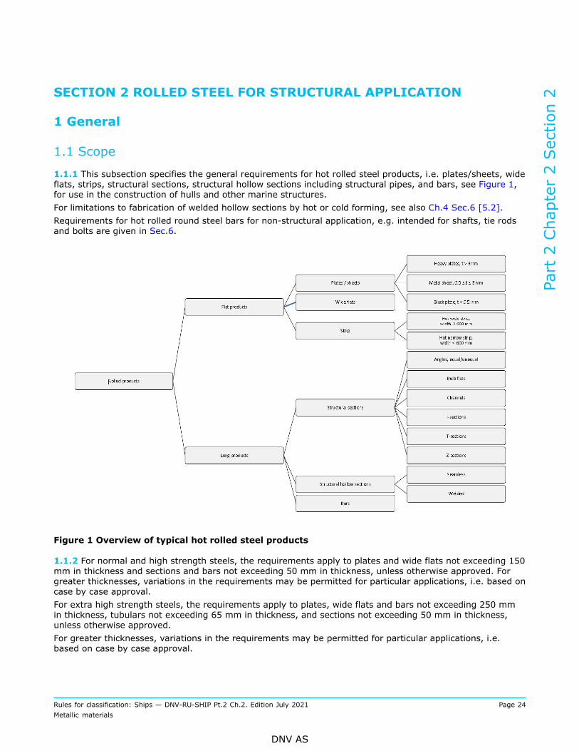
1.1.1 This subsection specifies the general requirements for hot rolled steel products, i.e. plates/sheets, wideflats, strips, structural sections, structural hollow sections including structural pipes, and bars, see Figure 1,for use in the construction of hulls and other marine structures.For limitations to fabrication of welded hollow sections by hot or cold forming, see also Ch.4 Sec.6 [5.2].Requirements for hot rolled round steel bars for non-structural application, e.g. intended for shafts, tie rodsand bolts are given in Sec.6.
Figure 1 Overview of typical hot rolled steel products
1.1.2 For normal and high strength steels, the requirements apply to plates and wide flats not exceeding 150mm in thickness and sections and bars not exceeding 50 mm in thickness, unless otherwise approved. Forgreater thicknesses, variations in the requirements may be permitted for particular applications, i.e. based oncase by case approval.For extra high strength steels, the requirements apply to plates, wide flats and bars not exceeding 250 mmin thickness, tubulars not exceeding 65 mm in thickness, and sections not exceeding 50 mm in thickness,unless otherwise approved.For greater thicknesses, variations in the requirements may be permitted for particular applications, i.e.based on case by case approval.
Part 2 Chapter 2 Section 2
Rules for classification: Ships — DNV-RU-SHIP Pt.2 Ch.2. Edition July 2021 Page 24Metallic materials
DNV AS

1.1.3 Where required by the relevant design and construction parts of the rules, steel shall comply with therequirements of Ch.1, the general requirements of Sec.1 and the appropriate specific requirements of thissection. If the specific requirements differ from these general requirements, the specific requirements shallprevail.
1.1.4 Steels differing from the specific requirements given in this section e.g. with respect to chemicalcomposition, deoxidation practice, conditions of supply or mechanical properties may be accepted, subject tospecial approval. Such steels shall have the letter S appended to the corresponding NV grade, e.g. NV A36S.
1.1.5 Subject to approval and as an alternative to [1.1.3] and [1.1.4], materials which comply with otherstandards or proprietary specifications may be considered for acceptance provided such specifications givereasonable equivalence to the requirements of this section, or are approved case by case for a specificapplication, see Ch.1 Sec.1 [3.4].
2 Documentation and required compliance documentation
2.1 Compliance documents
2.1.1 General compliance document requirements are given in Sec.1 [3.1].
2.1.2 The manufacturer shall provide the type of compliance document required in the relevant constructionrules giving the following particulars for each test unit which has been accepted:
a) purchaser’s name, order number and, if known, the vessel identificationb) manufacturer’s namec) description of products and steel graded) identification marking of productse) steel making process, cast identification and chemical compositionf) for steel with a corrosion resistant steel designation: the weight percentage of each element added or
intentionally controlled for improving corrosion resistanceg) condition of supplyh) for QT steels: tempering temperature or recommended post-weld heat treatment temperaturei) state if rimming steel has been supplied for grade A sections (applicable for max. thickness 12.5 mm)j) results of mechanical tests, including traceable test identificationk) when products comply with the requirements of [6], the results of through thickness tensile tests and
ultrasonic testsl) results of any supplementary and additional test requirements specified.
Additionally, for extra high strength steels the following shall be given:
— Ceq, CET or Pcm value— surface quality and inspection results.
2.1.3 The manufacturer shall in writing confirm compliance with the rule requirements before the compliancedocument is endorsed by the surveyor. Pending final issuance of compliance documents, this applies forthe shipping statement. The following form of declaration will be accepted if stamped or printed on eachinspection certificate or shipping statement with the name of the manufacturer and signed by an authorizedrepresentative of the manufacturer:'We hereby certify that the material has been made by an approved process and has been satisfactorilytested in accordance with the Society's rules and standards for classification.'
2.1.4 When products for certification are made from semi-finished products delivered by a sub-supplier, seeCh.1 Sec.2 [4.2.4].
Part 2 Chapter 2 Section 2
Rules for classification: Ships — DNV-RU-SHIP Pt.2 Ch.2. Edition July 2021 Page 25Metallic materials
DNV AS

2.2 Documentation requirements
2.2.1 General documentation requirements are given in Sec.1 [3.2]. Additional manufacturer specificdocumentation requirements are given in Table 1.
Table 1 Qualification documentation for manufacturer
Item Documentation type Additional description
N, TM, QT BCA and CODsteels
Z270 - Records For rolling schedule:
— records providing start rolling temperature,start and stop finishing rolling temperatures,deformation ratios, and where applicable,accelerated cooling start and stop temperatures,as well as heat treatment condition and significantparameters, such as holding temperature andholding time
— the records shall be presented to the surveyor onrequest.
BCA steels Z270 - Records For large scale testing, requirements as per [7.1.2].For small scale testing, requirements as per DNV-CG-0240.
2.3 Survey, inspection and testing requirements
2.3.1 General survey, inspection and testing requirements are given in Sec.1 [3.3]. Additional specificrequirements are given in Table 2, as further detailed in this section.
Table 2 Additional survey and testing requirements
Survey, inspection and testing item Description
Chemical composition — Required for all materials— the surveyor may require the content of impurity elements
such as tin (Sn), antimony (Sb) and arsenic (As) to bedetermined when recycled scrap or contaminated ore is used.
Tensile test and impact toughness test Required for all grades covered by this chapter unless otherwisespecified.
Through thickness tensile test Required for materials with specified through thicknessproperties.
Fracture mechanics test Fracture mechanics testing (CTOD test) is required in the courseof manufacturer approval testing for all materials of grade NVD47, NV E47, NV D47BCA, NV E47BCA, as well as for all strengthgrades with suffix COD or BCACOD. For production testingfracture mechanics testing is not required, unless otherwisestated.
Test for brittle crack arrestability Crack arrest toughness or crack arrest temperature testing isrequired for all BCA grade steels and strength 47 COD gradesteels.
Part 2 Chapter 2 Section 2
Rules for classification: Ships — DNV-RU-SHIP Pt.2 Ch.2. Edition July 2021 Page 26Metallic materials
DNV AS

Survey, inspection and testing item Description
Non-destructive testing — Seams of welded hollow sections; see specific requirements in[2.11.9]
— steels with through thickness properties, see specificrequirements in [6].
Manufacturing parameters It is in general the manufacturer’s responsibility to ensurethat the process and production controls qualified through themanufacturer approval testing, are adhered to in production. Thisis in particular emphasized for steels with delivery conditions NRand TM, as well as steels manufactured as BCA, COD, RCU, RCBand RCW grades, see [7] to [9].
2.4 Grading system
2.4.1 The steels are classified by strength into three groups:
— normal strength steel (NS)— high strength steel (HS)— extra high strength steel (EHS).
Each strength group is further subdivided into grades, as given in [3] to [9].
2.4.2 Supplementary requirements are given as follows:
— Z-quality steels (grades with specified through thickness properties), see [6]— BCA steels (steels with brittle crack arresting properties), see [7]— COD steels (steels with crack initiation resistance), see [8]— corrosion resistant steels for cargo oil tanks (RCU, RCB, RCW), see [9].
Steels intended for high heat input welding ≥ 50 kJ/cm shall be specially approved. Approval is given on theapproval of manufacturer certificate using a high heat input welding notation, e.g. D32-W200, indicatingapproval of steel grade NV D32 for welding by heat input ≤ 200 kJ/cm.
2.5 Manufacture
2.5.1 All materials delivered with NV or works (W) certificate shall be made at works approved by theSociety for the type, grade and dimensions of steel being supplied and for the relevant steelmaking andprocessing route, e.g. delivery condition, see Ch.1 Sec.2 [2.2.2]. Rolling mills without own steelmaking shalluse starting material supplied by works approved by the Society.
2.5.2 Steel shall be manufactured by an electric or one of the basic oxygen processes or any other processinvolving secondary refining approved by the Society.
2.5.3 Steel shall be cast in metal ingot moulds or by continuous casting. Sufficient discard shall be made toensure soundness in the finished product. Unless otherwise approved, the reduction ratio shall be at least 3to 1. For slab to plate, reduction ratio applies for the thickness reduction. For other products, the reductionratio requirement applies for the cross section reduction.
2.5.4 Conditions of supply shall be in accordance with [2.7].
2.5.5 It is the manufacturer’s responsibility to ensure that effective manufacture and process controls andwhere relevant, qualified or approved processes are implemented and adhered to in production. Wheredeviation from the controls occurs and this could produce products of inferior quality, the manufacturer shall
Part 2 Chapter 2 Section 2
Rules for classification: Ships — DNV-RU-SHIP Pt.2 Ch.2. Edition July 2021 Page 27Metallic materials
DNV AS

investigate to determine the cause and establish countermeasures to prevent its recurrence. Investigationreports to this effect along with additional information as the Society may require shall be made available tothe surveyor on request. The frequency and extent of testing for subsequent products is at the discretion ofthe Society.
2.6 Chemical composition
2.6.1 The chemical composition of each cast shall be determined on a sample taken preferably during thepouring of the cast and shall be within the specified limits in [3] to [9]. When multiple casts are tapped into acommon ladle, the ladle analysis shall apply and be within the specified limits.Variations from the chemical compositions given may be allowed for grades supplied in the thermo-mechanical rolled condition or when thicknesses exceed 50 mm, provided that these variations are inaccordance with an approved specification.
2.6.2 The composition shall be determined after all alloying additions have been made and sufficient timeallowed for such an addition to homogenize.
2.6.3 Elements designated as residual elements in the individual specifications shall not be intentionallyadded to the steel. The content of such elements shall be reported.
2.6.4 The manufacturer shall adopt adequate control in order to prevent accumulation of harmful elementsin the product, e.g. tin, antimony and arsenic. This is particularly relevant for steelmaking where recycledscrap is used as raw material, and where the ore may contain high levels of harmful elements.
2.6.5 When required, the carbon equivalent value (Ceq, Pcm or CET) shall be calculated. For further detailsand formulas, see Ch.1 Sec.2 [3.3].
Guidance note:Where requirements for Ceq or Pcm are not specified, maximum values given in EN 10225 may be used as guidance.
---e-n-d---o-f---g-u-i-d-a-n-c-e---n-o-t-e---
2.6.6 The requirements for elements designated as fine grain elements (Al, Nb, V and Ti) are given in eachsubsection [3] to [9]. Each combination of fine grain elements is subject to approval through the approval ofmanufacturer process, and is listed on the approval of manufacturer certificates. The applicable combinationof fine grain elements shall, unless otherwise approved, follow the minimum limits given in Table 3 and themaximum limits given in subsections [3] to [9].
Table 3 Requirements for fine grain elements
Fine grain elements, minimum content [%]Approved singleelement orcombinationof elements
Al 1) Nb V Ti
Al
0.020 2)
0.02 3)
0.018 4)- - -
Nb - 0.02 - -
V - - 0.05 -
Ti - - - 0.007
Al+Nb 0.015 0.010 - -
Part 2 Chapter 2 Section 2
Rules for classification: Ships — DNV-RU-SHIP Pt.2 Ch.2. Edition July 2021 Page 28Metallic materials
DNV AS
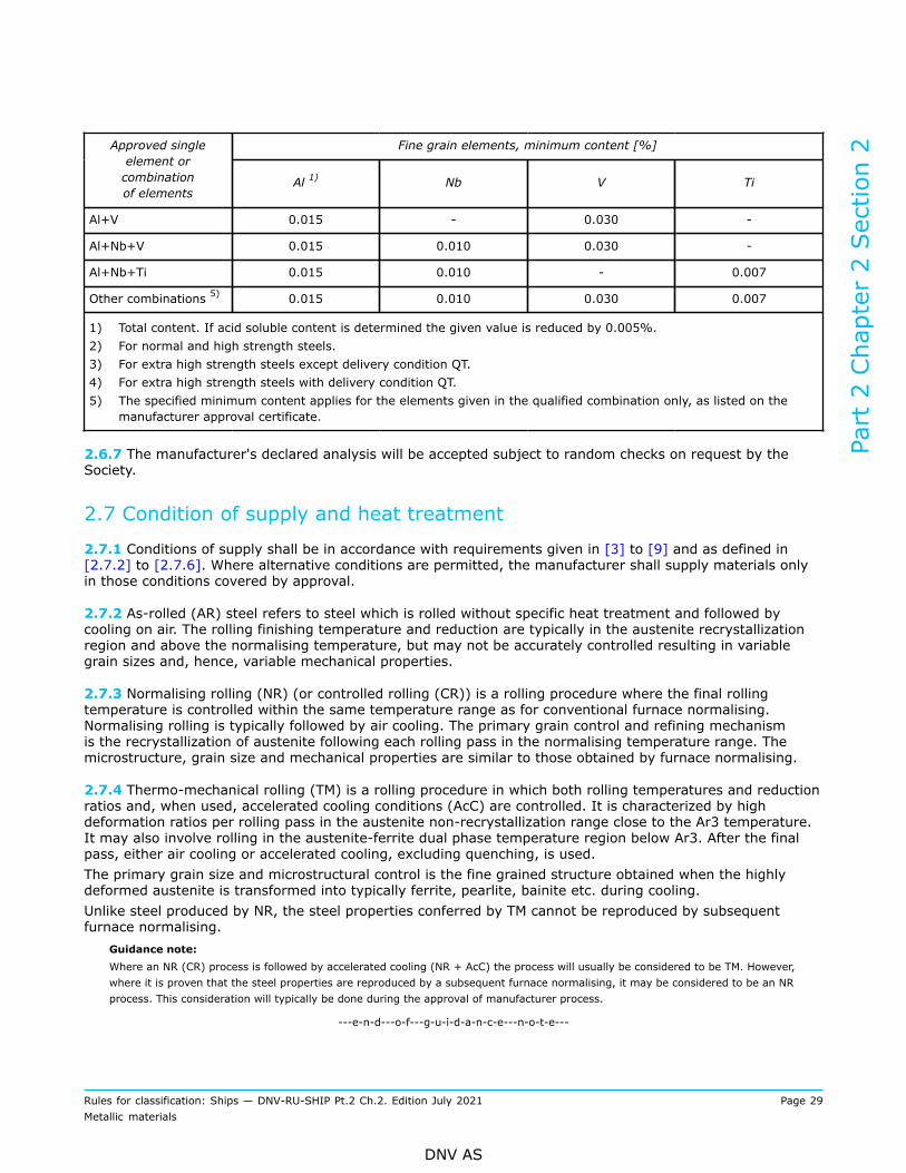
Fine grain elements, minimum content [%]Approved singleelement orcombinationof elements
Al 1) Nb V Ti
Al+V 0.015 - 0.030 -
Al+Nb+V 0.015 0.010 0.030 -
Al+Nb+Ti 0.015 0.010 - 0.007
Other combinations 5) 0.015 0.010 0.030 0.007
1) Total content. If acid soluble content is determined the given value is reduced by 0.005%.2) For normal and high strength steels.3) For extra high strength steels except delivery condition QT.4) For extra high strength steels with delivery condition QT.5) The specified minimum content applies for the elements given in the qualified combination only, as listed on the
manufacturer approval certificate.
2.6.7 The manufacturer's declared analysis will be accepted subject to random checks on request by theSociety.
2.7 Condition of supply and heat treatment
2.7.1 Conditions of supply shall be in accordance with requirements given in [3] to [9] and as defined in[2.7.2] to [2.7.6]. Where alternative conditions are permitted, the manufacturer shall supply materials onlyin those conditions covered by approval.
2.7.2 As-rolled (AR) steel refers to steel which is rolled without specific heat treatment and followed bycooling on air. The rolling finishing temperature and reduction are typically in the austenite recrystallizationregion and above the normalising temperature, but may not be accurately controlled resulting in variablegrain sizes and, hence, variable mechanical properties.
2.7.3 Normalising rolling (NR) (or controlled rolling (CR)) is a rolling procedure where the final rollingtemperature is controlled within the same temperature range as for conventional furnace normalising.Normalising rolling is typically followed by air cooling. The primary grain control and refining mechanismis the recrystallization of austenite following each rolling pass in the normalising temperature range. Themicrostructure, grain size and mechanical properties are similar to those obtained by furnace normalising.
2.7.4 Thermo-mechanical rolling (TM) is a rolling procedure in which both rolling temperatures and reductionratios and, when used, accelerated cooling conditions (AcC) are controlled. It is characterized by highdeformation ratios per rolling pass in the austenite non-recrystallization range close to the Ar3 temperature.It may also involve rolling in the austenite-ferrite dual phase temperature region below Ar3. After the finalpass, either air cooling or accelerated cooling, excluding quenching, is used.The primary grain size and microstructural control is the fine grained structure obtained when the highlydeformed austenite is transformed into typically ferrite, pearlite, bainite etc. during cooling.Unlike steel produced by NR, the steel properties conferred by TM cannot be reproduced by subsequentfurnace normalising.
Guidance note:Where an NR (CR) process is followed by accelerated cooling (NR + AcC) the process will usually be considered to be TM. However,where it is proven that the steel properties are reproduced by a subsequent furnace normalising, it may be considered to be an NRprocess. This consideration will typically be done during the approval of manufacturer process.
---e-n-d---o-f---g-u-i-d-a-n-c-e---n-o-t-e---
Part 2 Chapter 2 Section 2
Rules for classification: Ships — DNV-RU-SHIP Pt.2 Ch.2. Edition July 2021 Page 29Metallic materials
DNV AS

2.7.5 Normalising (N) is a separate heat treatment after rolling involving heating above the criticaltemperature, Ac3, and in the lower end of the austenite recrystallization region for a specific period oftime (austenitising), followed by air cooling, to produce a homogeneous, fine grained ferrite-pearlitemicrostructure.
2.7.6 Quenching and tempering (QT). Quenching (Q) is a heat treatment process in which the steel is heatedto an appropriate temperature above Ac3, held for a specific period of time, and followed by cooling at a ratesufficient for the formation of typically a martensite or bainite microstructure. Quenched steels are typicallyhard and brittle. Tempering (T) subsequent to quenching is reheating of the steel to a temperature belowAc1 and maintaining at that temperature for a specific period of time. Tempering improves the ductility andtoughness of quenched materials through microstructural changes, but reduces the hardness and strength.Furthermore, the quenching process results in material residual stress which is to some extent released/reduced by the subsequent tempering.The result of quenching followed by tempering is typically steels combining high strength with goodtoughness.
2.7.7 It is the manufacturer's responsibility to ensure that the rolling schedules for NR (CR) and TM specifiedand qualified through the manufacturer approval testing are adhered to during production. Productionrecords to this effect shall be made available to the surveyor on request. Where deviation from the qualifiedprogrammed rolling schedules occurs, the manufacturer shall ensure that each affected rolled piece is testedand that an investigation is carried out according to [2.5.5].
2.7.8 For normalising and for quenching and tempering, the furnace temperature uniformity shall becalibrated at regular intervals and provided to the surveyor on request.
2.7.9 Other delivery conditions than those listed above may be accepted based on special evaluation andapproval. Extended qualification through the approval of manufacturer process will be considered for eachrelevant case. The approved delivery conditions are listed on the approval of manufacturer certificates.
2.8 Test material and test specimens for mechanical testing
2.8.1 Test material shall be fully representative of the sample product and, where appropriate, shall not becut from the sample product until heat treatment has been completed. Test material or test specimens shallnot be separately heat-treated in any way.
2.8.2 The size, thickness location and preparation of test specimens and the procedures used for mechanicaltesting shall comply with the relevant requirements of Ch.1 Sec.3, see also [2.8.8].
2.8.3 Test material shall be suitably marked to identify them with the products represented.
2.8.4 Test material shall be taken from the following positions:
— plates and wide flats with a width≥ 600 mm:the test material shall be taken at the square cut end of the piece approximately one-quarter width froma long edge and unless otherwise agreed, equal to or less than one-quarter width from a short edge, seeTable 4.
— flats with a width < 600 mm, channels, beams, bulb flats and other sections:the test material shall be taken at approximately 1/3 of the width from an edge, see Table 4. Whereindicated, the test samples may alternatively be taken from a position approximately 1/4 of the widthfrom the web centre line or axis.
— bars and other similar products:the test material shall be taken at a depth one-third of the radius below the surface or, in the case of non-cylindrical sections, at a depth one-third of the half-diagonal from the surface, see Table 4.
Part 2 Chapter 2 Section 2
Rules for classification: Ships — DNV-RU-SHIP Pt.2 Ch.2. Edition July 2021 Page 30Metallic materials
DNV AS

Table 4 Position of test material
Plates and flats Angles
Unequal angles Channels and beams
Part 2 Chapter 2 Section 2
Rules for classification: Ships — DNV-RU-SHIP Pt.2 Ch.2. Edition July 2021 Page 31Metallic materials
DNV AS

Sections (joists) Bulb flats
Flats and rounds (bars)
2.8.5 The following definitions relevant to orientation of test specimens apply:
— longitudinal: Longitudinal axis of test specimen parallel to the principal direction of rolling— transverse: Longitudinal axis of test specimen perpendicular to the principal direction of rolling.
2.8.6 Unless otherwise agreed, the test specimens shall be oriented as follows:
Part 2 Chapter 2 Section 2
Rules for classification: Ships — DNV-RU-SHIP Pt.2 Ch.2. Edition July 2021 Page 32Metallic materials
DNV AS
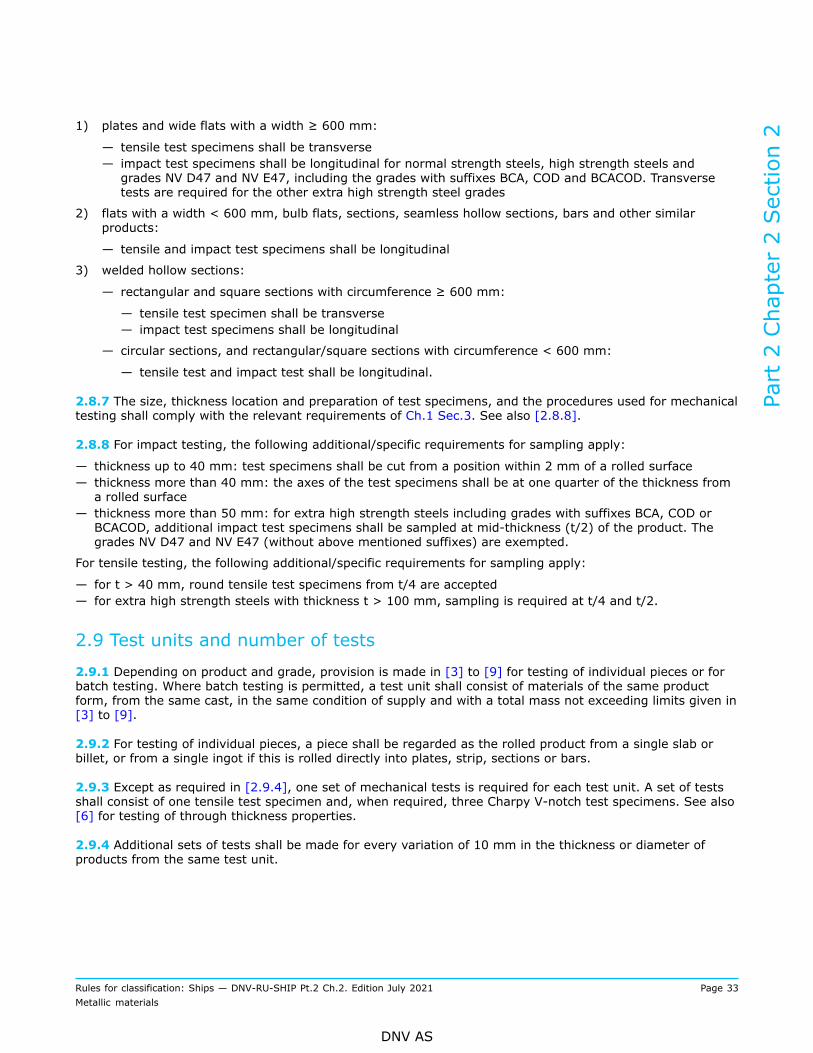
1) plates and wide flats with a width ≥ 600 mm:
— tensile test specimens shall be transverse— impact test specimens shall be longitudinal for normal strength steels, high strength steels andgrades NV D47 and NV E47, including the grades with suffixes BCA, COD and BCACOD. Transversetests are required for the other extra high strength steel grades
2) flats with a width < 600 mm, bulb flats, sections, seamless hollow sections, bars and other similarproducts:
— tensile and impact test specimens shall be longitudinal
3) welded hollow sections:
— rectangular and square sections with circumference ≥ 600 mm:
— tensile test specimen shall be transverse— impact test specimens shall be longitudinal
— circular sections, and rectangular/square sections with circumference < 600 mm:
— tensile test and impact test shall be longitudinal.
2.8.7 The size, thickness location and preparation of test specimens, and the procedures used for mechanicaltesting shall comply with the relevant requirements of Ch.1 Sec.3. See also [2.8.8].
2.8.8 For impact testing, the following additional/specific requirements for sampling apply:
— thickness up to 40 mm: test specimens shall be cut from a position within 2 mm of a rolled surface— thickness more than 40 mm: the axes of the test specimens shall be at one quarter of the thickness froma rolled surface
— thickness more than 50 mm: for extra high strength steels including grades with suffixes BCA, COD orBCACOD, additional impact test specimens shall be sampled at mid-thickness (t/2) of the product. Thegrades NV D47 and NV E47 (without above mentioned suffixes) are exempted.
For tensile testing, the following additional/specific requirements for sampling apply:
— for t > 40 mm, round tensile test specimens from t/4 are accepted— for extra high strength steels with thickness t > 100 mm, sampling is required at t/4 and t/2.
2.9 Test units and number of tests
2.9.1 Depending on product and grade, provision is made in [3] to [9] for testing of individual pieces or forbatch testing. Where batch testing is permitted, a test unit shall consist of materials of the same productform, from the same cast, in the same condition of supply and with a total mass not exceeding limits given in[3] to [9].
2.9.2 For testing of individual pieces, a piece shall be regarded as the rolled product from a single slab orbillet, or from a single ingot if this is rolled directly into plates, strip, sections or bars.
2.9.3 Except as required in [2.9.4], one set of mechanical tests is required for each test unit. A set of testsshall consist of one tensile test specimen and, when required, three Charpy V-notch test specimens. See also[6] for testing of through thickness properties.
2.9.4 Additional sets of tests shall be made for every variation of 10 mm in the thickness or diameter ofproducts from the same test unit.
Part 2 Chapter 2 Section 2
Rules for classification: Ships — DNV-RU-SHIP Pt.2 Ch.2. Edition July 2021 Page 33Metallic materials
DNV AS

2.10 Mechanical properties
2.10.1 The material shall meet the mechanical properties specified in [3] to [9].
2.10.2 If the results do not meet the specified requirements, the re-test procedures in Ch.1 Sec.2 [3.8] maybe adopted, see also [2.5.5]. Where the products are submitted to heat treatment or re-heat treatment, allthe tests previously performed shall be repeated and the results shall meet the specified requirements.For re-heat treatment, the products shall not be re-austenitized more than two times, unless otherwiseapproved.
2.11 Inspection and tolerances
2.11.1 Surface inspection and verification of dimensions including shape and straightness are theresponsibility of the manufacturer. Acceptance by the surveyor of material later found to be defective shallnot absolve the manufacturer from this responsibility.
2.11.2 Products shall have a workmanlike finish consistent with the method of manufacture and shall be freefrom internal and surface defects prejudicial to the use of the material for the intended application. Cracks,injurious surface flaws, shells (over lapping material with non-metallic inclusion), sand patches, scabs,blisters, laminations and sharp edged seams (elongated defects) visually evident on surface and/or edgeof plate are not accepted and require rejection or repair, irrespective of their size and number. Acceptancecriteria for other imperfections such as pitting, rolled-in scale, indentations, and roll marks, scratches andgrooves, which may occur under normal manufacturing conditions, shall be EN 10163-2 class A for plates/wide flats, and minimum EN10163-3 class C for sections. A precondition is that the remaining thicknessunder the imperfections remains within the thickness tolerances for the product. Other recognized standardsmay be accepted by the Society, provided equivalent or higher requriements are met. Total affected areawith imperfection not exceeding the specified limits shall not exceed 15% of the total surface in question. Forrepair of defects, see [2.12].If plates and wide flats are ordered with ultrasonic inspection, this shall be made in accordance with anaccepted standard at the discretion of the Society. Verfication of internal soundness is the responsibility ofthe manufacturer. The acceptance of internal soundness by the Society's Surveyor shall not absolve themanufacturer from this responsibility.
2.11.3 The responsibility for meeting the surface finish requirements rests with the manufacturer of thematerial, who shall take the necessary manufacturing precautions and shall inspect the products prior todelivery. At that stage, however, rolling or heat treatment scale may conceal surface discontinuities anddefects. If, during the subsequent descaling or working operations, the material is found to be defective, theSociety may require materials to be repaired or rejected.The surface quality inspection method shall be in accordance with recognized national or internationalstandards agreed between purchaser and the manufacturer, accepted by the Society.If agreed by the manufacturer and purchaser, steel may be ordered with improved surface finish over andabove these requirements.
Guidance note:Cosmetic appearance is not considered. Purchaser should specify additional requirements to the surface quality where this iscritical for the intended application.Internal defects, e.g. inclusions/sand patches (see EN10163-1) making the steel prone to lamination, may to some extent beconsidered consistent with method of manufacture, unless Z-quality steels is specified, see subsection [6]. Purchasers shouldspecify additional requirements to the internal quality (non-destructive test, e.g. ultrasonic testing) where this is critical for theintended application.
---e-n-d---o-f---g-u-i-d-a-n-c-e---n-o-t-e---
Part 2 Chapter 2 Section 2
Rules for classification: Ships — DNV-RU-SHIP Pt.2 Ch.2. Edition July 2021 Page 34Metallic materials
DNV AS
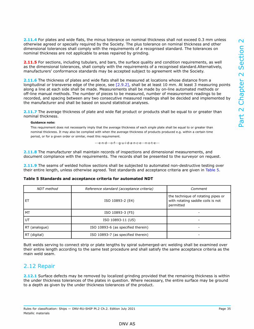
2.11.4 For plates and wide flats, the minus tolerance on nominal thickness shall not exceed 0.3 mm unlessotherwise agreed or specially required by the Society. The plus tolerance on nominal thickness and otherdimensional tolerances shall comply with the requirements of a recognised standard. The tolerances onnominal thickness are not applicable to areas repaired by grinding.
2.11.5 For sections, including tubulars, and bars, the surface quality and condition requirements, as wellas the dimensional tolerances, shall comply with the requirements of a recognised standard.Alternatively,manufacturers' conformance standards may be accepted subject to agreement with the Society.
2.11.6 The thickness of plates and wide flats shall be measured at locations whose distance from alongitudinal or transverse edge of the piece, see [2.9.2], shall be at least 10 mm. At least 3 measuring pointsalong a line at each side shall be made. Measurements shall be made by on-line automated methods oroff-line manual methods. The number of pieces to be measured, number of measurement readings to berecorded, and spacing between any two consecutive measured readings shall be decided and implemented bythe manufacturer and shall be based on sound statistical analyses.
2.11.7 The average thickness of plate and wide flat product or products shall be equal to or greater thannominal thickness.
Guidance note:This requirement does not necessarily imply that the average thickness of each single plate shall be equal to or greater thannominal thickness. It may also be complied with when the average thickness of products produced e.g. within a certain timeperiod, or for a given order or similar, meet this requirement.
---e-n-d---o-f---g-u-i-d-a-n-c-e---n-o-t-e---
2.11.8 The manufacturer shall maintain records of inspections and dimensional measurements, anddocument compliance with the requirements. The records shall be presented to the surveyor on request.
2.11.9 The seams of welded hollow sections shall be subjected to automated non-destructive testing overtheir entire length, unless otherwise agreed. Test standards and acceptance criteria are given in Table 5.
Table 5 Standards and acceptance criteria for automated NDT
NDT method Reference standard (acceptance criteria) Comment
ET ISO 10893-2 (E4)the technique of rotating pipes orwith rotating saddle coils is notpermitted
MT ISO 10893-3 (F5) -
UT ISO 10893-11 (U5) -
RT (analogue) ISO 10893-6 (as specified therein) -
RT (digital) ISO 10893-7 (as specified therein) -
Butt welds serving to connect strip or plate lengths by spiral submerged-arc welding shall be examined overtheir entire length according to the same test procedure and shall satisfy the same acceptance criteria as themain weld seam.
2.12 Repair
2.12.1 Surface defects may be removed by localized grinding provided that the remaining thickness is withinthe under thickness tolerances of the plates in question. Where necessary, the entire surface may be groundto a depth as given by the under thickness tolerances of the product.
Part 2 Chapter 2 Section 2
Rules for classification: Ships — DNV-RU-SHIP Pt.2 Ch.2. Edition July 2021 Page 35Metallic materials
DNV AS

2.12.2 Local grinding repairs where the remaining thickness of the repaired area is less than that given bythe under thickness tolerance, are accepted provided that:
— the thickness is in no place reduced by more than 7% of the nominal thickness, but in no case by morethan 3 mm
— each single ground area does not exceed 0.25 m2
— the total area of local grinding does not exceed 2% of the total surface area— the ground areas have smooth transitions to the surrounding surface— ground areas lying in a distance less than their average width to each other shall be regarded as onesingle area
— ground areas lying opposite each other on both surfaces shall not decrease the product thickness by morethan 7% or 3 mm, whichever is the less
— complete elimination of the defects shall be verified by NDT.
2.12.3 Surface defects which cannot be dealt with as in [2.12.1] or [2.12.2] may be repaired by chipping orgrinding followed by welding, subject to the surveyor's consent and under his supervision, provided that all ofthe following is complied with:
— after removal of defects and before welding, the thickness of the product shall not be reduced by morethan 20% of the nominal thickness. For occasional defects with depths exceeding the 20% limit, specialconsideration by the Society is necessary
— for repair of defects such as unacceptable imperfections, cracks, shells or seams, complete removal of thedefect shall be confirmed by suitable MT or PT before welding
— welding is carried out by qualified welders using an approved procedure with low hydrogen weldingconsumable for the appropriate steel grade
— the welding procedure is qualified using the requirements for butt welds according to Ch.4 Sec.5— each single welded area does not exceed 0.125 m2
— the total area of welded areas does not exceed 2% of the surface area of the side involved— the distance between any two welds is not less than their average width— the welds are made with an excess layer of beads and then ground flush with the product surface— the repair shall be carried out by qualified welders using an approved procedure for the appropriate steelgrade. The electrodes shall be of low hydrogen type and shall be dried in accordance with the electrodemanufacturer's requirements and protected against rehumidification before and during welding
— when deemed necessary, the repaired product is normalised or otherwise suitably post-weld heat-treated— the weld repairs shall be subjected to suitable non destructive testing such as magnetic particle or byliquid penetrant testing
— if weld repair depth exceeds 3 mm, UT may be requested by the Society. If required, ultrasonic testing(UT) shall be carried out in accordance with an approved procedure
— wherever possible, products which will be supplied in the normalised or quenched and tempered conditionshall be repair welded prior to the heat treatment.
2.12.4 Products with delivery condition NR or TM shall, where appropriate further processing cannotbe ensured, receive a stress-relieve heat treatment after welding according to the manufacturer'srecommendation.
2.12.5 For every repair weld, the manufacturer shall prepare a report containing details of the size andlocation of the defects, the welding repair procedure and any heat treatment applied. The manufacturershall present this report to the surveyor. The surveyor may require the repaired product to be presented forsurvey.
2.13 Identification
2.13.1 Every finished product shall be clearly marked by the manufacturer in at least one place with theSociety's brand and the following particulars:
Part 2 Chapter 2 Section 2
Rules for classification: Ships — DNV-RU-SHIP Pt.2 Ch.2. Edition July 2021 Page 36Metallic materials
DNV AS

a) manufacturer’s name or trade markb) steel grade, e.g. NV E36c) when products comply with the requirements of [6], the grade shall include the suffix Z25 or Z35, e.g.
NV E36Z25d) a suffix indicating the delivery condition (N, NR, TM, TM+AcC, TM+DQ or QT) shall be added for all extra
high strength steels, e.g. NV E420TMe) for steel grades where CTOD properties have been verified the suffix COD shall be included, see [8]f) identification number, cast number or other marking which will enable the full history of the product to
be tracedg) if required by the purchaser, his order number or other identification mark.
Durable marking for unique identification and traceability of the product is required.Guidance note:Hard stamping is normally used except where this may be detrimental to the material, in which case stencilling, painting or electricetching may be used. Other marking systems giving durable identification and traceability may as well be accepted. Thin plates,stainless steel and non-ferrous plates are normally not marked by hard stamping but rather by paint or similar systems.
---e-n-d---o-f---g-u-i-d-a-n-c-e---n-o-t-e---
2.13.2 The particulars in [2.13.1], but excluding the manufacturer's name or trade mark where this isembossed on finished products, shall be encircled with paint or otherwise marked to be easily recognisable.
2.13.3 For marking of bundles of products, see Ch.1 Sec.2 [4.1.3].
2.13.4 Where individually tested rolled lengths of plates (test piece/parent plate) are cut to more than oneplate, each plate shall be marked in a manner identifying its relationship to the original length.
3 Normal strength steel
3.1 Scope
3.1.1 These requirements are supplementary to [1] and apply to normal strength steel. Provision is made forfour grades with specified minimum yield strength of 235 MPa and based on the specified impact toughness.
3.2 Chemical composition
3.2.1 The chemical composition and deoxidation practice shall comply with the limits given in Table 6. Whenfine grain practice is applied, the requirements of Table 10 for Al, Nb, V and Ti shall apply.
Table 6 Chemical composition limits1)2) and deoxidation practice for normal strength steel
Grade C3) Si Mn3) P S Al Deoxidation practice
for t ≤ 50 mm: any method except rimmedsteel5)NV A 0.214) 0.50 Min.
2.5 × C 0.035 0.035 -
for t > 50 mm: killed steel
for t ≤ 50 mm: any method except rimmedsteelNV B 0.21 0.35 Min. 0.806) 0.035 0.035 -
for t > 50 mm: killed steel
NV D 0.21 0.10-0.35 Min. 0.60 0.035 0.035 - for t ≤ 25 mm: killed steel
Part 2 Chapter 2 Section 2
Rules for classification: Ships — DNV-RU-SHIP Pt.2 Ch.2. Edition July 2021 Page 37Metallic materials
DNV AS

Grade C3) Si Mn3) P S Al Deoxidation practice
Min. 0.0207) for t > 25 mm: killed and fine grain treatedsteel
NV E 0.18 0.10-0.35 Min. 0.70 0.035 0.035 Min. 0.0207) killed and fine grain treated
1) Given value is maximum content ([%] by weight) unless shown as a range or as a minimum.2) Unless otherwise approved, the following additional limits apply:
— Cu maximum 0.35%— Cr maximum 0.20%— Ni maximum 0.40%— Mo maximum 0.08%.
3) C + 1/6 Mn shall not exceed 0.40%.
4) Maximum 0.23% for sections.
5) Rimmed steel may be accepted for sections up to 12.5 mm thickness subject to special approval.
6) Minimum 0.60% when the steel is impact tested.
7) Total content. Acid soluble content, if determined instead, shall be minimum 0.015%.
3.3 Condition of supply and heat treatment
3.3.1 The condition of supply shall comply with the requirements given in Table 7.
Table 7 Conditions of supply for normal strength steel
Grade Thickness, t [mm] Plates Sections
t ≤ 50 AR, NR, N, TM AR, NR, N, TMNV A, NV B
50 < t ≤ 150 AR 1), NR, N, TM AR 1), NR, N, TM
t ≤ 35 AR, NR, N, TM AR, NR, N, TMNV D
35 < t ≤ 150 NR, N, TM AR 1), NR, N, TM
NV E t ≤ 150 N, TM AR 1), NR 1), N, TM
1) Products may be supplied in this condition when especially agreed, e.g. through the manufacturer approval.
3.4 Mechanical properties
3.4.1 The mechanical properties shall comply with the values specified in Table 8.
Table 8 Mechanical properties for normal strength steel
Impact energy, minimum average [J] 1)
t ≤ 50
[mm]
50 < t ≤ 70
[mm]
70 < t ≤ 150
[mm]Grade
Yieldstrength
ReHminimum
[MPa]
Tensile strength
Rm[MPa]
Elongation
A5
minimum
[%]
Testtemperature
[°C] L T L T L T
Part 2 Chapter 2 Section 2
Rules for classification: Ships — DNV-RU-SHIP Pt.2 Ch.2. Edition July 2021 Page 38Metallic materials
DNV AS

NV A
NV B
NV D
NV E
235 400 to 520 22 5)
+20
0
-20
-40
-2)
27 3)
27
27
-2)
20 3)
20
20
34 4)
34
34
34
24 4)
24
24
24
41 4)
41
41
41
27 4)
27
27
27
1) Test direction shall follow [2.8.6].2) Manufacturer shall ensure (e.g. through regular in-house tests) that material of grade NV A with thickness less than
50 mm meets an impact toughness energy of minimum 27 J at +20°C.3) Testing of the impact toughness is not required for grade NV B steel with t ≤ 25 mm. Manufacturer shall ensure
(e.g. through regular in-house tests) that material of grade NV B with thickness less than 25 mm meets an impacttoughness energy of minimum 27 J at 0°C.
4) Testing of the impact toughness is not required for grade NV A over 50 mm thickness when the material is producedusing fine grain practice and supplied in N condition. Manufacturer shall ensure (e.g. through regular in-house tests)that material of grade NV A with thickness more than 50 mm meets an impact toughness energy of minimum 27 Jat +20°C.
5) For full thickness flat test specimens with width 25 mm and gauge length 200 mm, the minimum elongation [%] isrequired as follows:
Thickness[mm] t ≤ 5 5 < t ≤ 10 10 < t
≤ 15 15 < t ≤ 20 20 < t ≤ 25 25 < t ≤ 30 30 < t≤ 40 40 < t ≤ 50
All grades 14 16 17 18 19 20 21 22
3.4.2 For tensile testing, the total mass of products in a test unit shall be maximum 50 tonnes. For impacttesting, the maximum size of a test unit shall be as given in Table 9.
Table 9 Test units for impact testing of normal strength steel
Grade Thickness, t [mm] Plates Sections
t ≤ 50 not required not requiredNV A
50 < t ≤ 150 50 tonnes not required
NV B 25 < t ≤ 150 50 tonnes 1, 2) 50 tonnes 2)
NV D t ≤ 150 50 tonnes 1, 2) 50 tonnes 2)
NV E t ≤ 150 Each piece 25 tonnes 3)
1) Maximum 25 tonnes for plates over 50 mm in thickness supplied in the normalising rolled (NR) condition.2) Maximum 25 tonnes for plates and sections supplied in the as rolled (AR) condition.3) Maximum 15 tonnes for sections supplied in the as rolled (AR) or normalising rolled (NR) condition.
4 High strength steel
4.1 Scope
4.1.1 These requirements are supplementary to [1] and apply to high strength steel. Provision is made forfour strength levels with specified minimum yield strength 265 MPa, 315 MPa, 355 MPa and 390 MPa. Eachstrength level is further subdivided into four grades based on the specified impact toughness.
Part 2 Chapter 2 Section 2
Rules for classification: Ships — DNV-RU-SHIP Pt.2 Ch.2. Edition July 2021 Page 39Metallic materials
DNV AS

4.2 Chemical composition
4.2.1 The chemical composition shall comply with the limits given in Table 10. Except for NV A27S withthickness less than 25 mm, the steel grades shall be killed and fine grain treated. NV A27S in thicknesses upto and including 25 mm may be semi-killed or killed and without fine grain treatment.
4.2.2 For TM steels, the carbon equivalent value (Ceq) shall comply with the limits given in Table 11.
Table 10 Chemical composition limits 1) for high strength steel
Grade C Si Mn P S Cr Mo Ni Cu Al Nb V Ti N
NV A27S, NV D27S,
NV E27S0.18 0.50
0.70
to
1.60
0.035 0.035 0.20 0.08 0.40 0.35 3) 0.053)
0.103)
0.023)4) -
NV A32, NVD32, NV E32,
NV A36, NVD36, NV E367),
NV A40, NVD40, NV E407)
0.18 0.50
0.90
to
1.602)
0.035 0.035 0.20 0.08 0.40 0.35 3) 0.053)
0.103)
0.023)4) -
NV F27S, NV F32,
NV F36, NV F400.16 0.50
0.90
to
1.60
0.025 0.025 0.20 0.08 0.80 0.35 3) 0.053)
0.103)
0.023)4)
0.0095)
1) Ggiven value is maximum content (by weight) unless shown as a range or as a minimum.2) Minimum 0.70% for thicknesses up to and including 12.5 mm.3) The steel shall contain grain refining elements Al, Nb, V or Ti, either singly or in any combination, see [2.6.6]. The
total content of Nb+V+Ti shall not exceed 0.12%.4) Maximum 0.05% Ti for TM steels subjected to agreement.5) 0.012% if Al is present.6) For NV E36 BCA and NV E40 BCA as per [7] the following limits are prevailing: %Mn = 0.90-2.00%, %Pmax =
0.020%, %Smax = 0.020%, %Cumax = 0.50%, %Crmax = 0.25%, %Nimax = 2.0%.
Table 11 Maximum carbon equivalent values (Ceq) for high strength steel supplied in TM condition
Grade t ≤ 50 [mm] 50 < t ≤ 100 [mm] 100 < t ≤ 150 [mm]
NV A27S, NV D27S, NV E27S, NV F27S 0.34 0.36 0.38
NV A32, NV D32, NV E32, NV F32 0.36 0.38 0.40
NV A36, NV D36, NV E36, NV F36 0.38 0.40 0.42
NV A40, NV D40, NV E40, NV F40 0.40 0.42 0.45
4.2.3 For NV E36 BCA and NV E40 BCA, according to [7] the carbon equivalent value (Ceq) shall comply withthe limits as follows:
— for NV E36 BCA: Ceq max = 0.47%— for NV E40 BCA: Ceq max = 0.49%.
Part 2 Chapter 2 Section 2
Rules for classification: Ships — DNV-RU-SHIP Pt.2 Ch.2. Edition July 2021 Page 40Metallic materials
DNV AS

4.3 Condition of supply and heat treatment
4.3.1 The condition of supply shall comply with the requirements given in Table 12.
Table 12 Conditions of supply for high strength steel
Grade Grain refiningelement Thickness, t [mm] Plates Sections
t ≤ 20 AR, NR, N, TM AR, NR, N, TM
20 < t ≤ 35 AR 1), NR, N, TM AR, NR, N, TMAl or anycombinations with Al
35 < t ≤ 150 NR, N, TM, QT AR 1), NR, N, TM, QT
t ≤ 12.5 AR, NR, N, TM AR, NR, N, TM
NV A27S,
NV A32,
NV A36Any combination
without Al 12.5 < t ≤ 150 NR, N, TM, QT AR 1), NR, N, TM, QT
t ≤ 12.5 AR, NR, N, TM AR, NR, N, TMNV A40 Any
12.5 < t ≤ 150 NR, N, TM, QT NR, N, TM, QT
t ≤ 20 AR, NR, N, TM AR, NR, N, TM
20 < t ≤ 25 AR 1), NR, N, TM AR, NR, N, TMAl or anycombinations with Al
25 < t ≤ 150 NR, N, TM, QT AR 1), NR, N, TM, QT
t ≤ 12.5 AR, NR, N, TM AR, NR, N, TM
NV D27S,
NV D32,
NV D36Any combination
without Al 12.5 < t ≤ 150 NR, N, TM, QT AR 1), NR, N, TM, QT
NV D40 Any t ≤ 150 NR, N, TM, QT NR, N, TM, QT
t ≤ 50 N, TM, QT AR 1), NR 1),N, TM, QT
NV E27S,
NV E32,
NV E36
Any
50 < t ≤ 150 N, TM, QT NR 1), N, TM, QT
NV F27S,
NV F32,
NV F36
Any t ≤ 150 N, TM, QT NR 1), N, TM, QT
NV E40,
NV F40Any t ≤ 150 N, TM, QT N, TM, QT
1) Products may be supplied in this condition when agreed.
4.4 Mechanical properties
4.4.1 The mechanical properties shall comply with the values given in Table 13.
4.4.2 For tensile testing, the total mass of products in a test unit shall be maximum 50 tonnes. For impacttesting, the maximum size of a test unit shall be as given in Table 14.
4.4.3 Additional requirements concerning through thickness properties (Z-ductility) are given in [6].
Part 2 Chapter 2 Section 2
Rules for classification: Ships — DNV-RU-SHIP Pt.2 Ch.2. Edition July 2021 Page 41Metallic materials
DNV AS

Table 13 Mechanical properties for high strength steel
Impact energy, minimum average [J] 1)
t ≤ 50
[mm]
50 < t ≤ 70
[mm]
70 < t ≤ 150
[mm]Grade
Yieldstrength
ReHminimum
[MPa]
Tensilestrength
Rm[MPa]
Elongation
A5
minimum
[%]
Testtemperature
[°C] L T L T L T
NV A27S
NV D27S
NV E27S
NV F27S
265 400 to 530 22 2)
0
-20
-40
-60
27 20 34 24 41 27
NV A32
NV D32
NV E32
NV F32
315 440 to 570 22 2)
0
-20
-40
-60
31 22 38 26 46 31
NV A36
NV D36
NV E36
NV F36
355 490 to 630 21 2)
0
-20
-40
-60
34 24 41 27 50 34
NV A40
NV D40
NV E40
NV F40
390 510 to 660 20 2)
0
-20
-40
-60
39 26 46 31 55 37
1) Test direction shall follow [2.8.6].2) For full thickness flat test specimens with width 25 mm and gauge length 200 mm, the minimum elongation [%] is
required as follows:
Thickness[mm] t ≤ 5 5 < t
≤ 10 10 < t ≤ 15 15 < t≤ 20
20 <t ≤ 25 25 < t ≤ 30 30 < t ≤ 40 40 < t ≤ 50
Strengthlevels 27Sand 32
14 16 17 18 19 20 21 22
Strengthlevel 36 13 15 16 17 18 19 20 21
Strengthlevel 40 12 14 15 16 17 18 19 20
Part 2 Chapter 2 Section 2
Rules for classification: Ships — DNV-RU-SHIP Pt.2 Ch.2. Edition July 2021 Page 42Metallic materials
DNV AS

Table 14 Test units for impact testing of high strength steels
Grades Delivery condition Thickness [mm] Plates Sections
AR All 25 tonnes 25 tonnes
≤ 50 50 tonnesNR
> 50 25 tonnes50 tonnes
NV A27SNV D27S
NV A32
NV D32
NV A36
NV D36
NV A40
NV D40
N, TM All 50 tonnes 50 tonnes
NV A27SNV D27S
NV A32
NV D32
NV A36
NV D36
QT All 50 tonnes 50 tonnes
NV A40NV D40
QT All each piece 25 tonnes
AR, NR All each piece 15 tonnesNV E27SNV F27S
NV E32
NV F32
NV E36
NV F36
NV E40
NV F40
N, TM, QT All each piece 25 tonnes
5 Extra high strength steel
5.1 Scope
5.1.1 These requirements are supplementary to [1] and apply to extra high strength steel. Provision is madefor eight strength levels with specified minimum yield strength 420 MPa, 460 MPa, 500 MPa, 550 MPa, 620MPa, 690 MPa, 890 MPa and 960 MPa, see Table 15 and Table 19. Each strength level is further subdividedinto four grades (with prefix A, D, E and F) based on the specified impact toughness, except for the strengthlevel of 890 MPa and 960 MPa for which prefix F is not applicable.
Guidance note 1:The extra high strength steel grades NV D47 and NV E47 (including all grades with suffix COD, BCA or BCACOD) are speciallydesigned for hull structural application in container ships. Specific manufacturer approval requirements for qualification of thesegrades are detailed in approval of manufacturer programme DNV-CP-0348.
---e-n-d---o-f---g-u-i-d-a-n-c-e---n-o-t-e---
Part 2 Chapter 2 Section 2
Rules for classification: Ships — DNV-RU-SHIP Pt.2 Ch.2. Edition July 2021 Page 43Metallic materials
DNV AS

Guidance note 2:Before subjecting steels produced by both thermo-mechanical rolling or quenched and tempered after rolling to further heatingfor forming or stress relieving, or using high heat-input welding, special consideration should be given to the possibility of aconsequent reduction in mechanical properties.
---e-n-d---o-f---g-u-i-d-a-n-c-e---n-o-t-e---
5.2 Method of manufacture
5.2.1 Steel making processVacuum degassing shall be used for any of the following:a) all steels with enhanced through thickness propertiesb) all steels of strength levels 690 MPa, 890 MPa and 960 MPa.The steel shall be fully killed, fine grain treated and shall have fine grain structure. The fine grain practiceshall be as detailed in the approved manufacturing specification, see also [2.6.6].
Guidance note:A fine grain structure has an equivalent index ≥ 6 determined by micrographic examination in accordance with ISO 643 oralternative test method.
---e-n-d---o-f---g-u-i-d-a-n-c-e---n-o-t-e---
The steels shall contain nitrogen binding elements as detailed in the approved manufacturing specification.Also see note 4 in Table 15.
5.3 Chemical composition
5.3.1 The chemical composition and deoxidation practice shall comply with the limits given in Table 15. Thesteel grades shall be killed and fine grain treated.Maximum Ceq, CET and Pcm values shall follow the values given in Table 16.
Part 2 Chapter 2 Section 2
Rules for classification: Ships — DNV-RU-SHIP Pt.2 Ch.2. Edition July 2021 Page 44Metallic materials
DNV AS

Table 15 Chemical composition 1) - extra high strength steels
Delivery condition2) N/NR TM QT N, TM, QT
Grades
NV A420
NV A460
NV D420
NV D460
NV E420
NV E460
NV A420
NV A460
NV A500
NV A550
NV A620
NV A690
NV A890
NV D420
NV D460
NV D500
NV D550
NV D620
NV D690
NV D890
NV E420
NV E460
NV E500
NV E550
NV E620
NV E690
NV E890
NV F420
NV F460
NV F500
NV F550
NV F620
NV F690
NV A420
NV A460
NV A500
NV A550
NV A620
NV A690
NV A890
NV A960
NV D420
NV D460
NV D500
NV D550
NV D620
NV D690
NV D890
NV D960
NV E420
NV E460
NV E500
NV E550
NV E620
NV E690
NV E890
NV E960
NV F420
NV F460
NV F500
NV F550
NV F620
NV F690
3)
NV D47
NV D47COD
NV D47BCA
NVD47BCACOD
NV E47
NV E47COD
NV E47BCA
NVE47BCACOD
C 0.20 0.18 0.16 0.14 0.18 0.18
Mn 1.0-1.70 1.0-1.70 1.70 0.90-2.00
Si 0.60 0.60 0.80 0.55
P 4) 0.030 0.025 0.025 0.020 0.025 0.020 0.020
S4) 0.025 0.020 0.025 0.010 0.015 0.010 0.020
Altotal56) 0.02 0.02 0.018 0.020
Nb7) 0.05 0.05 0.06 0,02-0,057)
V 7) 0.20 0.12 0.12 0.05-0.107)
Ti 7) 0.05 0.05 0.05 0.02
Ni 8) 0.80 2.00 2.01.0
for BCAgrades: 2.0
Cu 0.55 0.55 0.500.35for BCA
grades: 0.50
Cr7) 0.30 0.50 1.500.25for BCA
grades: 0.50
Mo 7) 0.10 0.50 0.70 0.08
N 0.025 0.025 0.015 0.0109)
B10) - - - 0.0005
Part 2 Chapter 2 Section 2
Rules for classification: Ships — DNV-RU-SHIP Pt.2 Ch.2. Edition July 2021 Page 45Metallic materials
DNV AS

Delivery condition2) N/NR TM QT N, TM, QT
Grades
NV A420
NV A460
NV D420
NV D460
NV E420
NV E460
NV A420
NV A460
NV A500
NV A550
NV A620
NV A690
NV A890
NV D420
NV D460
NV D500
NV D550
NV D620
NV D690
NV D890
NV E420
NV E460
NV E500
NV E550
NV E620
NV E690
NV E890
NV F420
NV F460
NV F500
NV F550
NV F620
NV F690
NV A420
NV A460
NV A500
NV A550
NV A620
NV A690
NV A890
NV A960
NV D420
NV D460
NV D500
NV D550
NV D620
NV D690
NV D890
NV D960
NV E420
NV E460
NV E500
NV E550
NV E620
NV E690
NV E890
NV E960
NV F420
NV F460
NV F500
NV F550
NV F620
NV F690
3)
NV D47
NV D47COD
NV D47BCA
NVD47BCACOD
NV E47
NV E47COD
NV E47BCA
NVE47BCACOD
Oxygen ppm 11) - - 50 - 30 -
1) Given values are maximum content ([%] by weight) unless shown as a range or as minimum. The chemicalcomposition shall be determined by ladle analysis and shall meet the approved manufacturing specification at thetime of approval.
2) See [5.4] for definition of delivery conditions.3) When scrap material is being used in steel production, the amount of the following residual elements shall be
determined and reported and the levels shall not exceed: 0.03% As, 0.01% Sb, 0.02% Sn, 0.01% Pb, 0.01% Bi and0.005% Ca.
4) For sections the P and S content can be 0.005% higher than the specified value.5) Minimum limits for fine grain elements (Al, Nb, V, Ti) are specified in [2.6.6].6) The total aluminium to nitrogen ratio shall be a minimum of 2:1. When other nitrogen binding elements are used,
the minimum Al value and Al/N ratio do not apply.7) Total Nb+V+Ti ≤ 0.26% and Mo+Cr ≤ 0.65%, not applicable for QT steels. For BCA grades in addition: total Nb+V
+Ti ≤ 0.12%.8) Higher Ni content may be approved subject to qualification during manufacturer approval testing.9) N ≤ 0.012% if Al is present.10) B ≤ 0.005 may be added subject to qualification of maximum content during manufacturer approval testing.11) The requirement to maximum oxygen content is applicable to NV D890, NV E890, NV D960, and NV E960 only.
Part 2 Chapter 2 Section 2
Rules for classification: Ships — DNV-RU-SHIP Pt.2 Ch.2. Edition July 2021 Page 46Metallic materials
DNV AS

Table 16 Maximum Ceq, CET and Pcm values
Carbon equivalent [%] 1)
Ceq CET 2) Pcm 3)
Plates Sections Bars Tubulars all all
Strengthlevel
Deliverycondition
t ≤ 50 [mm]50 < t≤ 100[mm]
100 <t ≤ 250[mm]
t ≤ 50[mm]
t ≤ 250or
d ≤ 250
[mm]
t ≤ 65[mm] all all
N/NR 0.46 0.48 0.52 0.47 0.53 0.47 - -
TM 0.43 0.45 0.47 0.44 - - -420
QT 0.45 0.47 0.49 - - 0.46 - -
N/NR 0.50 0.52 0.54 0.51 0.55 0.51 0.25 -
TM 0.45 0.47 0.48 0.46 - - 0.30 0.23460
QT 0.47 0.48 0.50 - - 0.48 0.32 0.24
47 - 0.46 0.49 4) 0.49 - - - 0,32 0,22 4)
TM 0.46 0.48 0.50 - - - 0.32 0.24500
QT 0.48 0.50 0.54 - - 0.50 0.34 0.25
TM 0.48 0.50 0.54 - - - 0.34 0.25550
QT 0.56 0.60 0.64 - 0.56 0.36 0.28
TM 0.50 0.52 - - - - 0.34 0.26620
QT 0.56 0.60 0.64 - - 0.58 0.38 0.30
TM 0.56 - - - - - 0.36 0.30690
QT 0.64 0.66 0.70 - - 0.68 0.40 0.33
TM 0.60 - - - - - 0.38 0.28890
QT 0.68 0.75 - - - - 0.40 -
960 QT 0.75 - - - - - 0.40 -
1) Higher carbon equivalents may be accepted subject to pre-qualification by the manufacturer, see also [1.1.4] andCh.1 Sec.2 [2].
2) For steel grades NV 460 and higher, CET may be used instead of Ceq at the discretion of the manufacturer.3) For extra high strength steels in TM and QT condition and with carbon content not more than 0.12%, the specified
values for Pcm may be used instead of Ceq or CET at the discretion of the manufacturer.4) For BCA grades: Ceq max = 0.55%, Pcm max = 0.24%
5.4 Condition of supply and heat treatment
5.4.1 Conditions of supply shall be in accordance with requirements given in [3] and as defined in [2.7].Where alternative conditions are permitted, the manufacturer shall supply materials only in those conditionsfor which he has been approved.
Part 2 Chapter 2 Section 2
Rules for classification: Ships — DNV-RU-SHIP Pt.2 Ch.2. Edition July 2021 Page 47Metallic materials
DNV AS

Table 17 Condition of supply related to maximum thickness limits
Maximum thickness [mm]1)Delivery condition
Plates Sections Bars Tubulars
N 2502) 50 250 65
NR 150 3)
TM 150 50 - -
QT 1502) 50 - 50
1) Maximum thickness for steels of improved weldability is 100 mm unless otherwise agreed.2) Qualification for normalised (N) steels with thickness larger than 250 mm and QT steels with thickness larger than
150 mm is subject to the special consideration of the verifier.3) The maximum thickness limits of sections, bars and tubulars produced by NR process route are less than those
manufactured by N route, and shall be at the discretion of verifier.
5.5 Mechanical properties
5.5.1 The mechanical properties shall comply with the values given in Table 19. The extent of tensile andimpact testing shall be as specified in [5.5.2] and [5.5.3].Sampling and test direction of test specimens shall follow the requirements of [2.8].
5.5.2 Test unit for tensile testTensile test sample shall be randomly selected from each batch that is less than or equal to 25 tonnes, and tobe from the same cast, in the same delivery condition and of the same thickness.
5.5.3 Test unit for impact testFor impact testing, the following test units are applicable:
— for steel plates in N/NR or TM condition test sample shall be taken from each piece. For definition of piece,see [2.9.2]
— for steel plates in QT condition test sample shall be taken from each piece and each furnace batch. Forcontinuous heat treatment furnace, see also Ch.1 Sec.2 [3.4]
— for sections, bars and tubulars, test sample shall be taken from each batch of 25 tonnes or fractionthereof
— if the mass of the finished material is greater than 25 tonnes, one set of tests from each 25 tonnes andfraction thereof is required (e.g. consignment of 60 tonnes would require three (3) plates to be tested).Guidance note:For continuous heat treated products special consideration may be agreed to the number and location of test specimens.
---e-n-d---o-f---g-u-i-d-a-n-c-e---n-o-t-e---
5.5.4 Fracture mechanics testing (CTOD test) is required for the base material and coarse grained HAZ(GCHAZ) for NV D47 and NV E47 with suffixes COD, BCA and BCACOD, and shall be carried out in accordancewith the method described in Ch.1 Sec.3 [3.10]. Testing may be omitted if the CTOD properties have beenqualified through the manufacturer approval test and the qualified material and manufacturing process isadhered to.
— CTOD value for the base material shall be reported for reference— CTOD values of GCHAZ for NV D47BCA and NV E47BCA grades shall be reported for reference— acceptance criteria for CTOD values of GCHAZ for grades with suffix COD are given in [8.1.2].
Part 2 Chapter 2 Section 2
Rules for classification: Ships — DNV-RU-SHIP Pt.2 Ch.2. Edition July 2021 Page 48Metallic materials
DNV AS

Guidance note:Guidance on qualification of NV D47 and E47 with suffix COD, BCA and BCACOD are given in manufacturer approval programmeDNV-CP-0348.
---e-n-d---o-f---g-u-i-d-a-n-c-e---n-o-t-e---
Table 18 Mechanical properties for extra high strength steel
Yield strength ReH,minimum [MPa]1, 2, 3, 4)
Tensile strengthRm [MPa]2, 3, 4)
Impact energy,minimum average [J]Mechanical
propertiesNominal thickness [mm]5) Nominal
thickness [mm]5)
Elongationafter fractureminimum [%]L 0=5.65√S 0
2) For thickness, t [mm]
Steel grade anddelivery conditions
3 ≤ t≤ 50
50 < t≤ 100
100 <t ≤ 250
3 ≤ t≤ 100
100 <t ≤ 250 T L6)
Testtemp.[°C] t ≤ 250 7)
T (L)
NV A420
NVD420
NV E420
NV F420
N, NR,TM, QT
420 390 365 520-680 470-650 19 21
0
-20
-40
-60
28 (42)
NV A460
NVD460
NV E460
NV F460
N, NR,TM, QT
460 430 390 540-720 500-710 17 19
0
-20
-40
-60
31 (46)
t ≤ 70 70 <t ≤ 85
85 < t≤ 100
NV D47
NV E478)
TM, QT
460 460 - 570-720 - 17 19-20
-40 37(53)9)
45(64)9)
53(75)9)
t ≤ 150 7)
NV A500
NVD500
NV E500
NV F500
TM, QT 500 480 440 590-770 540-720 17 19
0
-20
-40
-60
33 (50)
NV A550
NVD550
NV E550
NV F550
TM, QT 550 530 490 640-820 590-770 16 18
0
-20
-40
-60
37 (55 )
NV A620
NVD620
NV E620
NV F620
TM, QT 620 580 560 700-890 650-830 15 17
0
-20
-40
-60
41 ( 62)
Part 2 Chapter 2 Section 2
Rules for classification: Ships — DNV-RU-SHIP Pt.2 Ch.2. Edition July 2021 Page 49Metallic materials
DNV AS
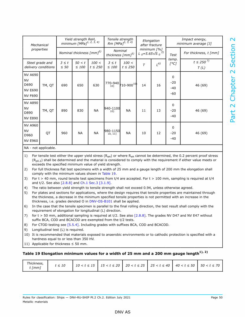
Yield strength ReH,minimum [MPa]1, 2, 3, 4)
Tensile strengthRm [MPa]2, 3, 4)
Impact energy,minimum average [J]Mechanical
propertiesNominal thickness [mm]5) Nominal
thickness [mm]5)
Elongationafter fractureminimum [%]L 0=5.65√S 0
2) For thickness, t [mm]
Steel grade anddelivery conditions
3 ≤ t≤ 50
50 < t≤ 100
100 <t ≤ 250
3 ≤ t≤ 100
100 <t ≤ 250 T L6)
Testtemp.[°C] t ≤ 250 7)
T (L)
NV A690
NVD690
NV E690
NV F690
TM, QT 690 650 630 770-94010) 710-90010) 14 16
0
-20
-40
-60
46 (69)
NV A890
NVD890
NV E890
TM, QT 890 830 NA 940-110010) NA 11 13
0
-20
-40
46 (69)
NV A960
NVD960
NV E960
QT 960 NA NA 980-115010, 11) NA 10 12
0
-20
-40
46 (69)
NA - not applicable.
1) For tensile test either the upper yield stress (ReH) or where ReH cannot be determined, the 0.2 percent proof stress(Rp0.2) shall be determined and the material is considered to comply with the requirement if either value meets orexceeds the specified minimum value of yield strength.
2) For full thickness flat test specimens with a width of 25 mm and a gauge length of 200 mm the elongation shallcomply with the minimum values shown in Table 19.
3) For t > 40 mm, round tensile test specimens from t/4 are accepted. For t > 100 mm, sampling is required at t/4and t/2. See also [2.8.8] and Ch.1 Sec.3 [3.1.9].
4) The ratio between yield strength to tensile strength shall not exceed 0.94, unless otherwise agreed.5) For plates and sections for applications, where the design requires that tensile properties are maintained through
the thickness, a decrease in the minimum specified tensile properties is not permitted with an increase in thethickness, i.e. grades denoted O in DNV-OS-B101 shall be applied.
6) In the case that the tensile specimen is parallel to the final rolling direction, the test result shall comply with therequirement of elongation for longitudinal (L) direction.
7) for t > 50 mm, additional sampling is required at t/2. See also [2.8.8]. The grades NV D47 and NV E47 withoutsuffix BCA, COD and BCACOD are exempted from the t/2 tests.
8) For CTOD testing see [5.5.4]. Including grades with suffixes BCA, COD and BCACOD.9) Longitudinal test (L) is required.10) It is recommended that materials exposed to anaerobic environments or to cathodic protection is specified with a
hardness equal to or less than 350 HV.11) Applicable for thickness ≤ 50 mm.
Table 19 Elongation minimum values for a width of 25 mm and a 200 mm gauge length1), 2)
Thickness,t [mm] t ≤ 10 10 < t ≤ 15 15 < t ≤ 20 20 < t ≤ 25 25 < t ≤ 40 40 < t ≤ 50 50 < t ≤ 70
Part 2 Chapter 2 Section 2
Rules for classification: Ships — DNV-RU-SHIP Pt.2 Ch.2. Edition July 2021 Page 50Metallic materials
DNV AS
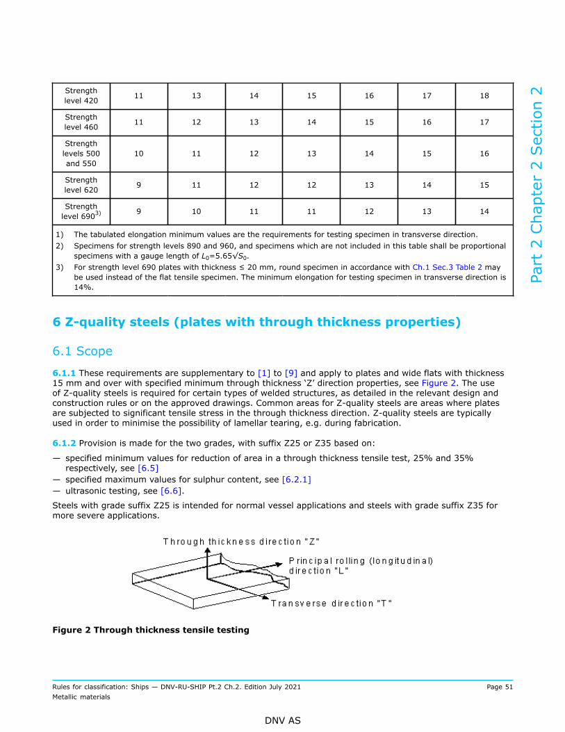
Strengthlevel 420 11 13 14 15 16 17 18
Strengthlevel 460 11 12 13 14 15 16 17
Strengthlevels 500and 550
10 11 12 13 14 15 16
Strengthlevel 620 9 11 12 12 13 14 15
Strengthlevel 6903) 9 10 11 11 12 13 14
1) The tabulated elongation minimum values are the requirements for testing specimen in transverse direction.2) Specimens for strength levels 890 and 960, and specimens which are not included in this table shall be proportional
specimens with a gauge length of L0=5.65√S0.3) For strength level 690 plates with thickness ≤ 20 mm, round specimen in accordance with Ch.1 Sec.3 Table 2 may
be used instead of the flat tensile specimen. The minimum elongation for testing specimen in transverse direction is14%.
6 Z-quality steels (plates with through thickness properties)
6.1 Scope
6.1.1 These requirements are supplementary to [1] to [9] and apply to plates and wide flats with thickness15 mm and over with specified minimum through thickness ‘Z’ direction properties, see Figure 2. The useof Z-quality steels is required for certain types of welded structures, as detailed in the relevant design andconstruction rules or on the approved drawings. Common areas for Z-quality steels are areas where platesare subjected to significant tensile stress in the through thickness direction. Z-quality steels are typicallyused in order to minimise the possibility of lamellar tearing, e.g. during fabrication.
6.1.2 Provision is made for the two grades, with suffix Z25 or Z35 based on:
— specified minimum values for reduction of area in a through thickness tensile test, 25% and 35%respectively, see [6.5]
— specified maximum values for sulphur content, see [6.2.1]— ultrasonic testing, see [6.6].
Steels with grade suffix Z25 is intended for normal vessel applications and steels with grade suffix Z35 formore severe applications.
Figure 2 Through thickness tensile testing
Part 2 Chapter 2 Section 2
Rules for classification: Ships — DNV-RU-SHIP Pt.2 Ch.2. Edition July 2021 Page 51Metallic materials
DNV AS

6.2 Chemical composition
6.2.1 The Z-quality steels shall be killed and fine grain treated. The ladle analysis sulphur content shall be≤ 0.008% unless alternative methods of improving through thickness properties have been approved. Forsulphur content ≤ 0.005%, reduced test unit size is accepted, see Table 20.
6.3 Manufacture
6.3.1 All materials shall be manufactured at works approved by the Society for the NV grade of Z-qualitysteel being supplied.
Guidance note:It is recommended that special steelmaking processes and techniques such as vacuum degassing, sulphide shape control orsuitable low sulphur techniques are used.
---e-n-d---o-f---g-u-i-d-a-n-c-e---n-o-t-e---
6.4 Test material
6.4.1 Test material shall be taken close to the longitudinal centerline from one end of each rolled piecerepresenting the test unit, see Figure 3 and Table 20.The longitudinal axes of the test specimens shall be perpendicular to the surface of the product.
6.4.2 The test material shall be large enough to accommodate the preparation of six test specimens. Threetest specimens shall be prepared while the rest of the sample remains for possible retest.
6.4.3 Round test specimens shall be prepared in accordance with a recognised standard, e.g. EN 10164 orASTM A770.
Figure 3 Plate and wide flat sampling position
Table 20 Test unit (batch) maximum size dependent on product and sulphur content
Sulphur content [%]Product
0.005 < S ≤ 0.008 S ≤ 0.005
Plates Each piece (parent plate)
Wide flats of nominal thickness ≤ 25 mm 10 tonnes
Wide flats of nominal thickness > 25 mm 20 tonnes
50 tonnes
Part 2 Chapter 2 Section 2
Rules for classification: Ships — DNV-RU-SHIP Pt.2 Ch.2. Edition July 2021 Page 52Metallic materials
DNV AS

6.5 Mechanical testing
6.5.1 The average reduction of area value of three test specimens shall be determined and meet thespecified minimum average value given in Table 21. One individual value may be below the specifiedminimum average value, but not less than the specified minimum individual value.
6.5.2 If the results do not meet the specified requirements, three additional test specimens from the samesample may be tested. The test unit will then be accepted provided that all the following conditions are met:
— the average value of six test specimens meets the specified minimum average value— not more than two of six individual values are lower than the specified minimum average value— no value is below the specified minimum individual value.
6.5.3 Where batch testing is permitted and the conditions for acceptance after retest in [6.5.2] are not met,the tested product shall be rejected. The remaining products in the test unit may be resubmitted individuallyfor test and accepted provided satisfactory results.
6.5.4 If the fracture of a test specimen occurs in the weld or in the heat affected zone the test is regarded asinvalid and shall be repeated on a new test specimen.
Table 21 Reduction of area acceptance values
Grade suffix Z25 Z35
Minimum average 25% 35%
Minimum individual 15% 25%
6.6 Ultrasonic testing
6.6.1 Each product shall be subjected to ultrasonic testing in the delivery condition. Testing shall beperformed in accordance with either EN 10160 and with acceptance criteria level S1/E1, or ASTM A578 withacceptance criteria level C. Details of the performance of testing including probe frequencies are described inthe applied standard.
7 BCA steels (steels with brittle crack arresting properties)
7.1 Scope
7.1.1 These requirements are supplementary to [1] to [9] and apply to brittle crack arrest (BCA) steels.Provision is made for steel plates, wide flats and sections with a thickness of more than 50 mm and withspecified minimum yield strength 355 MPa, 390 MPa and 460 MPa.
7.1.2 BCA steel is defined as steel plate with measured crack arrest properties, Kca, as specified in Table 22at -10°C determined by ESSO test (see Ch.1 Sec.3 [3.11]), or other methods based on the determinationof crack arrest temperature (CAT). BCA steels are subdivided into two grades BCA1 and BCA2 based on thespecified brittle crack arrest toughness
Part 2 Chapter 2 Section 2
Rules for classification: Ships — DNV-RU-SHIP Pt.2 Ch.2. Edition July 2021 Page 53Metallic materials
DNV AS

Table 22 Brittle crack arrest grades
Suffix to the steel grade Thickness range [mm] 1) Brittle crack arrest properties
Brittle crack arrest toughness
Kca at -10 °C [N/mm3/2]
Crack arrest temperature
CAT [°C]
BCA1 50 < t ≤ 100 6000 min. -10 or below
BCA2 80 < t ≤ 100 8000 min. As determined for themanufacturer approval
1) Lower thicknesses may be approved at the discretion of the Society.
To verify the brittle crack arrestability, either ESSO test to determine the crack arrest toughness Kca shallbe carried out, see Ch.1 Sec.3 [3.11], or double tension wide plate test to determine the crack arresttemperature CAT. The obtained brittle crack arrest toughness Kca, or the crack arrest temperature CAT,respectively, shall be reported.
Guidance note:Subject to approval, alternative test methods may be accepted for testing during production of BCA steels. DNV-CG-0240 Brittlecrack arrest materials for container ships provides information how this may be established. The use of small scale tests, e.g.drop weight tests in order to determine the nil ductility test temperature (NDTT), or other relevant tests, may be considered foracceptance provided that mathematical relationship between the test results of the small scale test and Kca or CAT can be shownto be valid. The Kca or CAT property, and its relationship with small scale tests are typically established during the manufacturerapproval testing of this particular NV grade, whereas small scale testing is subsequently carried out during production.
---e-n-d---o-f---g-u-i-d-a-n-c-e---n-o-t-e---
7.2 Chemical composition
7.2.1 As specified in [7.3.1] the manufacturer shall establish a specification for the chemical composition,with particular focus on elements which affect the BCA properties. The specified chemical composition shall ingeneral follow the requirements of the corresponding NV grade of non-BCA steel as given in [4] and [5]. Thechemical composition of samples taken from each ladle of each cast shall be determined by the manufacturerand shall be in accordance with the qualified specification. The manufacturer shall verify compliance.The specification may typically give ranges of each element as indicated in EN 10225-1 Option 17, under theprovision that the chemical composition range is also within the requirements given for the corresponding NVgrade of non-BCA steels.In the case of steels with certain resistance to crack initiation (COD steels) the stricter limitations as per[8.2] are applicable.
7.3 Manufacture and testing
7.3.1 Qualification of BCA steels: all materials shall be manufactured at works approved by the Society forthe grade of steel being supplied.The manufacturer shall establish a specification for the chemical composition, manufacturing process andproduction control for the BCA steels, with particular focus on parameters which affect the BCA properties.The specification for NV D36BCA, NV E36BCA, NV D40BCA and NV E40BCA may alternatively follow thechemical composition requirements for steel grades NV D47 and NV E47, see Table 15.The BCA steel grades corresponding to the manufacturer specification shall be qualified during the approvalof manufacturer process in accordance with the relevant approval programme DNV-CP-0348.
Part 2 Chapter 2 Section 2
Rules for classification: Ships — DNV-RU-SHIP Pt.2 Ch.2. Edition July 2021 Page 54Metallic materials
DNV AS

Guidance note:CTOD test of base material and GCHAZ is required as part of the qualification, see DNV-CP-0348. The CTOD test results arereported for information and acceptance criteria for grades without COD designation are not specified.
---e-n-d---o-f---g-u-i-d-a-n-c-e---n-o-t-e---
7.3.2 Testing during production: the frequency of testing is each test unit, see [2.9]. The size of a test unitshall be as defined for the corresponding steel grade without BCA properties, see [3] to [6]. In additiontesting for BCA property is required as follows (see also [7.1.2]):
— for NV grades with specified minimum yield strength 355 MPa and 390 MPa: Test frequency as per tensiletest (i.e. each cast and each thickness, max. test unit may be 50 tons)
— for NV grades with specified minimum yield strength 460 MPa: Test frequency is each piece.Guidance note:Approval for reduced extent of testing may be given based on statistics showing consistent good BCA properties combined with themanufacturers’ strict process and production control.
---e-n-d---o-f---g-u-i-d-a-n-c-e---n-o-t-e---
7.3.3 Production control: for steels manufactured as BCA steels, it is the manufacturer’s responsibility toensure that the qualified specification including process and production controls in operation are adhered to,see [7.3.1].
7.3.4 Changes to the process or failure to meet the specification: if the composition, process or productioncontrols are changed in any way, or any product fails to meet specifications, the manufacturer shall issue areport explaining the reasons, and, in the instance of product which fails to meet specifications, the measuresto prevent recurrence. The complete report shall be submitted to the Society along with such additionalinformation as the Society may require. The frequency of testing for subsequent products is at the discretionof the Society.
7.3.5 Declaration of conformance: by naming the steel as a NV BCA grade on the certificate, themanufacturer declares conformance with the qualified specification.
7.4 Identification
7.4.1 Identification shall be in accordance with [2.13]. Additionally, the grade shall include the brittle crackarrest steel designation suffix BCA, e.g. NV E40Z35BCA1.
8 COD steels (steels with crack initiation resistance)
8.1 Scope
8.1.1 These requirements are supplementary to [1] to [9] and apply to steels with certain resistance tocrack initiation (COD steels), i.e. which exhibit a certain fracture toughness in terms of crack tip openingdisplacement (CTOD). Provision is made for steel plates, wide flats and sections with a thickness of morethan 50 mm.
8.1.2 COD steel is defined as steels with measured minimum single CTOD value of 0.18 mm and minimumaverage CTOD value of 0.20 mm for notch position in GCHAZ. The average CTOD value is calculated based onat least three valid CTOD test results.
Part 2 Chapter 2 Section 2
Rules for classification: Ships — DNV-RU-SHIP Pt.2 Ch.2. Edition July 2021 Page 55Metallic materials
DNV AS
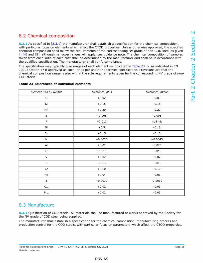
8.2 Chemical composition
8.2.1 As specified in [8.3.1] the manufacturer shall establish a specification for the chemical composition,with particular focus on elements which affect the CTOD properties. Unless otherwise approved, the specifiedchemical composition shall follow the requirements of the corresponding NV grade of non-COD steel as givenin [4] and [5], although narrower ranges will apply, see guidance note. The chemical composition of samplestaken from each ladle of each cast shall be determined by the manufacturer and shall be in accordance withthe qualified specification. The manufacturer shall verify compliance.The specification may typically give ranges of each element as indicated in Table 23, or as indicated in EN10225 Option 17 if approved as such, or as per another approved specification. Provisions are that thechemical composition range is also within the rule requirements given for the corresponding NV grade of non-COD steels.
Table 23 Tolerances of individual elements
Element [%] by weight Tolerance, plus Tolerance, minus
C +0.02 -0.03
Si +0.15 -0.15
Mn +0.20 -0.20
S +0.005 -0.005
P +0.010 no limit
Ni +0.5 -0.15
Cu +0.15 -0.15
N +0.0025 +0.0045
Al +0.02 -0.025
Nb +0.010 -0.010
V +0.02 -0.02
Ti +0.010 -0.010
Cr +0.10 -0.10
Mo +0.04 -0.06
B +0.0010 -0.0010
Ceq +0.02 -0.03
Pcm +0.02 -0.03
8.3 Manufacture
8.3.1 Qualification of COD steels: All materials shall be manufactured at works approved by the Society forthe NV grade of COD steel being supplied.The manufacturer shall establish a specification for the chemical composition, manufacturing process andproduction control for the COD steels, with particular focus on parameters which affect the CTOD properties.
Part 2 Chapter 2 Section 2
Rules for classification: Ships — DNV-RU-SHIP Pt.2 Ch.2. Edition July 2021 Page 56Metallic materials
DNV AS

The COD steel grade corresponding to the manufacturer specification shall be qualified during the approval ofmanufacturer process in accordance with the relevant approval programme DNV-CP-0348.
8.3.2 Production control: For steels manufactured as COD steels, it is the manufacturer’s responsibility toensure that the qualified specification including process and production controls in operation are adhered to,see [8.3.1].
8.3.3 Changes to the process or failure to meet the specification: If the composition, process or productioncontrols are changed in any way, or any product fails to meet specifications, the manufacturer shall issue areport explaining the reasons, and, in the instance of product which fails to meet specifications, the measuresto prevent recurrence. The complete report shall be submitted to the Society along with such additionalinformation as the Society may require. The frequency of testing for subsequent products is at the discretionof the Society.
8.3.4 Declaration of conformance: By naming the steel as a NV COD grade on the certificate, themanufacturer declares conformance with the qualified specification.
8.4 Identification
8.4.1 Identification shall be in accordance with [2.13]. Additionally, the grade shall include the designatedsuffix COD, e.g. NV E40Z35COD or NV E40Z35BCA1COD.
9 Corrosion resistant steels for cargo oil tanks
9.1 Scope
9.1.1 These requirements are supplementary to [1] to [6] and apply to corrosion resistant steels whensuch steel is used as the alternative means of corrosion protection for cargo oil tanks as specified in theperformance standard MSC.289 (87) of Regulation 3-11, Part A-1, Chapter II-1 of the SOLAS Convention(Corrosion protection of cargo oil tanks of crude oil tankers).
9.1.2 Provision is made for steel plates, wide flats and sections with a thickness up to 50 mm.
9.1.3 Corrosion resistant steels as defined within this chapter are steels whose corrosion resistanceperformance in the bottom or top of the internal cargo oil tank is tested and approved to satisfy therequirements in MSC.289 (87) in addition to other relevant requirements for vessel material, structuralstrength and construction. It is not intended that such steels shall be used for corrosion resistant applicationsin other areas of a vessel that are outside of those specified in the performance standard MSC.289 (87) ofRegulation 3-11, Part A-1, Chapter II-1 of the SOLAS Convention.
9.2 Chemical composition
9.2.1 The manufacturer shall establish a specification for the chemical composition when qualifying corrosionresistant steels, as documented in the approval of manufacturer process, with particular focus on elementsinfluencing the corrosion resistance properties. The specified chemical composition shall in general alsofollow the requirements of the corresponding NV grade given in [4] and [5]. The chemical composition of theproduced corrosion resistant steels shall comply with this specification.
9.2.2 The chemical composition of samples taken from each ladle of each cast shall be determined by themanufacturer, and shall be in accordance with the qualified specification. The manufacturer shall verifycompliance.
Part 2 Chapter 2 Section 2
Rules for classification: Ships — DNV-RU-SHIP Pt.2 Ch.2. Edition July 2021 Page 57Metallic materials
DNV AS

9.3 Manufacture
9.3.1 All materials shall be manufactured at works approved by the Society for the grade of corrosionresistant steel being supplied, and according to the process specification and chemical compositionspecification qualified through the manufacturer approval process.
9.3.2 The corrosion resistant steel grades shall be qualified during the approval process in accordance withthe relevant Society approval programme. Approval can be given for application in one of the following areasof a cargo oil tank:
a) lower surface of strength deck and surrounding structures (RCU)b) upper surface of inner bottom plating and surrounding structures (RCB)c) for both strength deck and inner bottom plating (RCW).
9.3.3 By naming the steel as RCU, RCB or RCW grade on the certificate, the manufacturer declaresconformance with the qualified specification.
9.4 Identification
9.4.1 Identification shall be in accordance with [2.13]. Additionally, the grade shall include the corrosiondesignation suffix RCU, RCB or RCW, e.g. NV E36RCU Z35.
10 Steels with higher ductility
10.1 Scope
10.1.1 These requirements are supplementary to [1] to [4] and [6] and apply to steels with higher ductility(HD steels). Provision is made for steel plates, wide flats and sections made of normal strength steels and ofsteels with strength levels 32 and 36 with a thickness not exceeding 50 mm.
10.1.2 HD steel is defined as steels with specified minimum elongation as listed in Table 24 or Table 25,respectively. The minimum elongation is higher than the minimum elongation specified in [3] and [4],respectively.
10.2 Chemical composition
10.2.1 The manufacturer shall establish a specification for the chemical composition when qualifying higherductility steels, as documented in the approval of manufacturer process, with particular focus on elementsinfluencing the elongation. The specified chemical composition shall in general also follow the requirementsof the corresponding NV grade given in [3] and [4]. The chemical composition shall be in accordance with thequalified specification. The manufacturer shall verify the compliance.
10.3 Manufacture
10.3.1 Qualification of HD steels: all materials shall be manufactured at works approved by the Society forthe NV grade of HD steel being supplied.The manufacturer shall establish a specification for the manufacturing process and production control for theHD steels, with particular focus on parameters which affect the elongation.The HD steel grade corresponding to the manufacturer specification shall be qualified during the approval ofmanufacturer process in accordance with DNV-CP-0243.
Part 2 Chapter 2 Section 2
Rules for classification: Ships — DNV-RU-SHIP Pt.2 Ch.2. Edition July 2021 Page 58Metallic materials
DNV AS

10.3.2 Production control: for steels manufactured as HD steels, it is the manufacturer’s responsibility toensure that the qualified specification, including process and production controls in operation, are adhered to.
10.3.3 Changes to the process or failure to meet the specification: if the composition, process or productioncontrols are changed in any way, or any product fails to meet specifications, the manufacturer shall issue areport explaining the reasons, and, in the instance of product which fails to meet specifications, the measuresto prevent recurrence. The complete report shall be submitted to the Society along with such additionalinformation as the Society may require. The frequency of testing for subsequent products is at the discretionof the Society.
10.3.4 Declaration of conformance: by naming the steel as a NV HD35 grade, or NV HD50 grade,respectively, on the certificate, the manufacturer declares conformance with the qualified specification.
10.4 Mechanical testing
10.4.1 The minimum elongation shall be determined and meet the specified minimum value given in Table24 or Table 25, respectively.
Table 24 Elongation at fracture acceptance values for proportional tensile test specimens
Strength level Elongation A5, minimum [%]
HD35 with 35% increased elongation
Normal strength HD35 30
Strength level 32 HD35 30
Strength level 36 HD35 28
HD50 with 50% increased elongation
Normal strength HD50 33
Strength level 32 HD50 33
Strength level 36 HD50 32
Table 25 Elongation at fracture acceptance values for tensile test specimen type B
Minimum elongation [%] for full thickness flat test specimens with width 25 mm and gauge length 200 mm is required asfollows:
Thickness[mm] t ≤ 5 5 < t
≤ 10 10 < t ≤ 15 15 < t≤ 20
20 <t ≤ 25 25 < t ≤ 30 30 < t ≤ 40 40 < t ≤ 50
HD35 with 35% increased elongation
NormalstrengthHD35
19 22 23 24 26 27 28 30
Strengthlevel 32HD35
19 22 23 24 26 27 28 30
Strengthlevel 36HD35
18 20 22 23 24 26 27 28
Part 2 Chapter 2 Section 2
Rules for classification: Ships — DNV-RU-SHIP Pt.2 Ch.2. Edition July 2021 Page 59Metallic materials
DNV AS
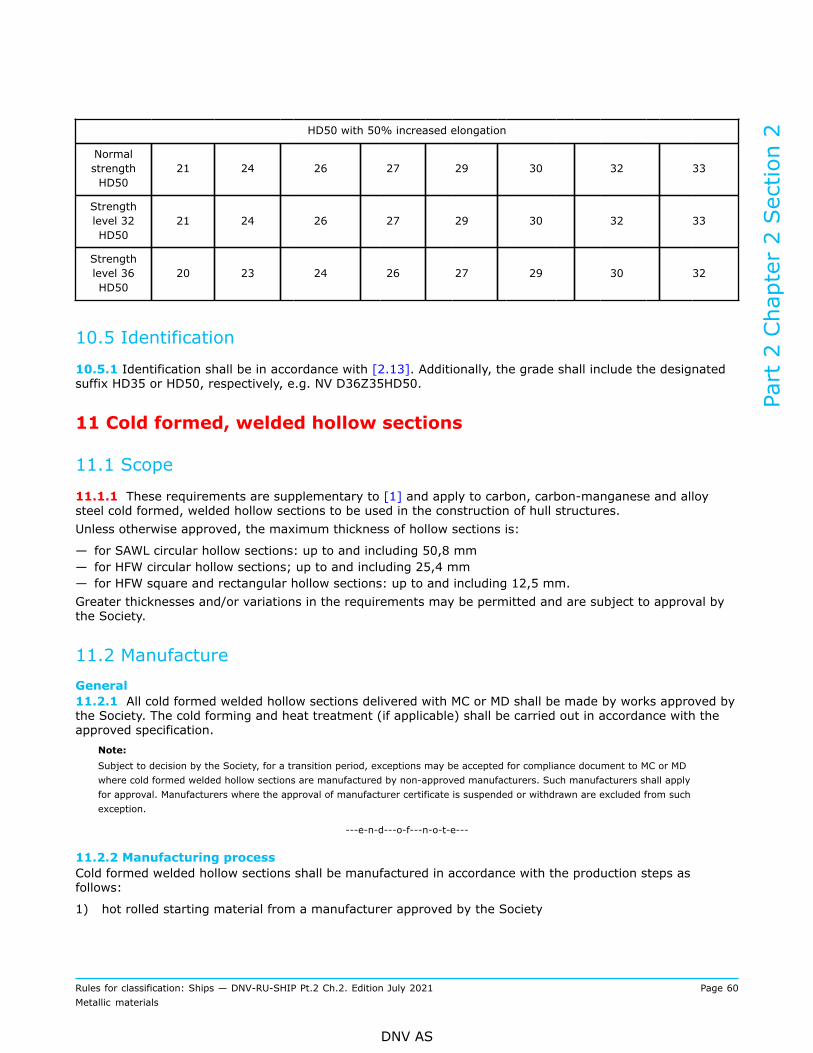
HD50 with 50% increased elongation
NormalstrengthHD50
21 24 26 27 29 30 32 33
Strengthlevel 32HD50
21 24 26 27 29 30 32 33
Strengthlevel 36HD50
20 23 24 26 27 29 30 32
10.5 Identification
10.5.1 Identification shall be in accordance with [2.13]. Additionally, the grade shall include the designatedsuffix HD35 or HD50, respectively, e.g. NV D36Z35HD50.
11 Cold formed, welded hollow sections
11.1 Scope
11.1.1 These requirements are supplementary to [1] and apply to carbon, carbon-manganese and alloysteel cold formed, welded hollow sections to be used in the construction of hull structures.Unless otherwise approved, the maximum thickness of hollow sections is:
— for SAWL circular hollow sections: up to and including 50,8 mm— for HFW circular hollow sections; up to and including 25,4 mm— for HFW square and rectangular hollow sections: up to and including 12,5 mm.Greater thicknesses and/or variations in the requirements may be permitted and are subject to approval bythe Society.
11.2 ManufactureGeneral11.2.1 All cold formed welded hollow sections delivered with MC or MD shall be made by works approved bythe Society. The cold forming and heat treatment (if applicable) shall be carried out in accordance with theapproved specification.
Note:Subject to decision by the Society, for a transition period, exceptions may be accepted for compliance document to MC or MDwhere cold formed welded hollow sections are manufactured by non-approved manufacturers. Such manufacturers shall applyfor approval. Manufacturers where the approval of manufacturer certificate is suspended or withdrawn are excluded from suchexception.
---e-n-d---o-f---n-o-t-e---
11.2.2 Manufacturing processCold formed welded hollow sections shall be manufactured in accordance with the production steps asfollows:
1) hot rolled starting material from a manufacturer approved by the Society
Part 2 Chapter 2 Section 2
Rules for classification: Ships — DNV-RU-SHIP Pt.2 Ch.2. Edition July 2021 Page 60Metallic materials
DNV AS

2) cold forming of starting material at ambient temperature into long hollow products with circular, squareor rectangular section, and open at both ends
3) welding of the cold formed starting materials by using an approved welding process to produce tubularproducts.
11.2.3 Starting materialWhere cold formed welded hollow sections shall be delivered with MC or MD, their starting material (i.e. coilsor plates) shall also be delivered with MC or MD from a manufacturer approved by the Society.The starting material, i.e. the steel grades used, shall meet the requirements of [1] to [5], unless otherwiseapproved.
11.2.4 Cold formingForming of materials shall be performed according to the approved procedures which outline the relevantcontrolled steps
11.2.5 WeldingThe following shall be complied with for manufacturing of cold formed welded hollow sections, unlessotherwise approved:
— automatic welding process shall be used, e.g. SAW, HFW or any other reliable and approved weldingprocess
— the WPS shall be qualified in accordance with Ch.4 Sec.5— low hydrogen welding consumables shall be used if relevant, e.g. for SAW— the welding operator shall be qualified in accordance with Ch.4 Sec.3.
11.2.6 Condition of supplyThe cold formed welded hollow sections shall be delivered in accordance with the manufacturer's approvedprocess.
11.3 Chemical composition
11.3.1 The chemical composition determined by heat analysis is required for each cast for the startingmaterial and comply with the requirements in [2] to [5].The surveyor may request product analysis for the purpose of investigation of material's traceability.
11.4 Mechanical testing11.4.1 Test unitA test unit is defined as a quantity of welded hollow sections that is made to the same specified outsidediameter and specified wall thickness, from the starting materials of the same batch defined in [2.9], andwith a total mass not exceeding limits given in [3] to [8] for plates and coils.Manufacturer's specification on test unit definition shall be approved by the Society.
11.4.2 Test methods and scopeDepending on product and grade, in addition to the provision made in [3] to [8] for testing of individualpieces or for batch testing for plates or coils, production testing shall be carried out in accordance with Table26.
Table 26 Test scope for production testing
Testing location Testing method Acceptance criteria
Section body 1) 1 tensile test. Base metal's requirements in [3] to [8].
Part 2 Chapter 2 Section 2
Rules for classification: Ships — DNV-RU-SHIP Pt.2 Ch.2. Edition July 2021 Page 61Metallic materials
DNV AS

Testing location Testing method Acceptance criteria
1 set of 3 pieces impact tests. Base metal's requirements in [3] to [8].
1 tensile test (transverse to the weld) 2). See Ch.4 Sec.5.
Impact tests 3). See Ch.4 Sec.5.
Weldment
1 root and 1 face bend specimens 4) 5). See Ch.4 Sec.5.
Corner region 6) 1 set of 3 pieces impact test at strain agedcondition.
See Pt.3 Ch.3 Sec.1 [2.7].
Note:
1) The testing is not required when the starting material is delivered with a MC.2) In case transverse test specimen cannot be taken due to restriction of hollow section's size, alternatively test
specimen with longitudinal axis parallel to the weld seam may be tested.3) Impact testing of weld metal and HAZ and specimen locations shall be performed as per Ch.4 Sec.5.4) In case the hollow section's wall thickness ≥ 12 mm, alternatively 2 side bend specimens may be tested.5) For round hollow sections alternatively the flattening test may be performed. In this case the following acceptance
criteria shall be complied with:
— when flattening to 2/3 of the original outside diameter: no weld opening shall occur— when flattening to 1/3 of the original outside diameter: no crack or break shall occur except than in the weld— flattening shall be performed until the opposite walls of the hollow section meet— during the entire test: the presence of laminar imperfections or burnt metal shall not become apparent.
6) Applicable for grade D/DH or higher stipulated in [3] to [5].
11.4.3 Optional testingWhen steel with improved through thickness properties (Z-steel) is required or specified in the order, thestarting material shall be manufactured and tested in accordance with [6].
Note:Further optional testing methods may be required by the purchaser, end user, or the Society, considering the intended application.
---e-n-d---o-f---n-o-t-e---
11.5 Inspection and tolerances11.5.1 Surface quality, dimensions, tolerances and massUnless otherwise required by the purchase order, the international recognized standards (e.g. EN10225-4)shall be complied with for the acceptance of surface quality, dimension, tolerance and mass.The ends of the hollow section shall be cut perpendicular to the axis of the product.HFW hollow sections shall be supplied with the external weld bead trimmed to an essentially flush condition.
Note:Trimming of inner weld profile for HFW hollow sections is normally at the discretion of the manufacturer, unless it is required bythe designer based on the evaluation results of its intended application. The fit for purpose evaluation may require fatigue strengthcalculation, enhanced NDT and/or trimming of inner weld profile, which shall be stipulated in the purchase order. The Society shallbe informed about this before certification.
---e-n-d---o-f---n-o-t-e---
11.5.2 Non destructive testingNDT procedures shall be established by the manufacturer and approved by the Society prior to productioncommencement.
Part 2 Chapter 2 Section 2
Rules for classification: Ships — DNV-RU-SHIP Pt.2 Ch.2. Edition July 2021 Page 62Metallic materials
DNV AS

The weld seams of welded hollow sections shall be subjected to automated non-destructive testing overtheir entire length, unless otherwise agreed. Test standards and acceptance criteria are given in Table 27 asminimum requirements.
Table 27 Standards and acceptance criteria for automated NDT
NDT method Standard Acceptance criteria Welding process
ET 1) ISO 10893-2 E4H HFW
MT 2) ISO 10893-3 F5 HFW
RT (analogue) ISO 10893-6 as specified therein 6) SAW
RT (digital) 3) ISO 10893-7 as specified therein 6) SAW
UT 4) 5) ISO 10893-11 U4 HFW, SAW
Note:
1) The technique of rotating pipes or with rotating saddle coils is not permitted.2) Calibration shall be carried out using an external reference notch.3) Alternative option to RT (analogue).4) For HFW sections when d (internal diameter) > 15 mm, an internal reference notch may be used in addition.5) Alternative option to RT.6) Image quality class A: X-ray examination technique with standard sensitivity.
Butt welds serving to connect strip or plate lengths by spiral submerged-arc welding shall be examined overtheir entire length according to the same test procedure and shall satisfy the same acceptance criteria as themain weld seam.
11.6 RepairRepair procedure shall be established by the manufacturer and agree with the Society.Surface discontinuities may be removed by the manufacturer by grinding, provided that the thickness of thehollow section after the repair is not less than the minimum permissible thickness in accordance with EN10219-2.Repair by welding is not permitted for the following cases:
— for the body of HFW and SAW hollow sections— for the weld seam of HFW hollow sections.Repair by welding is permitted for the weld seam of SAW hollow sections with the following conditions:
— The repair shall be carried out by qualified welders, using an approved WPS and type approved weldingconsumables according to Ch.4 for the appropriate steel grade. The consumables shall be of low hydrogentype and shall be dried in accordance with the consumable manufacturer's requirements and protectedagainst humidification before and during welding.
— The weld repairs shall be subjected to suitable non-destructive testing such as magnetic particle or liquidpenetrant testing.
For every repair weld, the manufacturer shall prepare a report containing details of the size and location ofthe defects, the welding repair procedure and any heat treatment applied. The manufacturer shall presentthis report to the surveyor. The surveyor may require the repaired product to be presented for survey.
11.7 IdentificationIdentification shall be in accordance with [2.13]. Additionally, the grade shall include the cold formed weldedhollow section definition suffix CW, e.g. NV E36 CW.
Part 2 Chapter 2 Section 2
Rules for classification: Ships — DNV-RU-SHIP Pt.2 Ch.2. Edition July 2021 Page 63Metallic materials
DNV AS

SECTION 3 ROLLED STEEL FOR BOILERS, PRESSURE VESSELS ANDSPECIAL APPLICATIONS
1 General
1.1 Scope
1.1.1 This section specifies the requirements for hot rolled steel products intended for use in the constructionof boilers and pressure vessels, tanks and process equipment for low temperature service, and rolledaustenitic and duplex (ferritic/austenitic) stainless steels. Application is ambient, elevated and lowtemperature service.Requirements for the manufacture of rolled bars for shafts, shanks, studs, bolts and other rotating parts arecovered by Sec.6.
1.1.2 Where required by the relevant design and construction parts of the rules, rolled steel shall complywith the general requirements of Sec.1 and [1], and the appropriate specific requirements of [2] to [5].Where the specific requirements differ from these general requirements, the specific requirements shallprevail.
1.1.3 Subject to approval and as an alternative to [1.1.2], materials which comply with other standards orproprietary specifications may be considered for acceptance provided such specifications give reasonableequivalence to the requirements of this section or are approved for a specific application, see Ch.1 Sec.1[3.4].
1.2 Required compliance documentation
1.2.1 General compliance document requirements are given in Sec.1 [3.1].
1.2.2 The manufacturer shall provide the type of compliance document required in the relevant constructionrules giving the following particulars for each test unit which has been accepted:
a) purchaser’s name, order number and, if known, the vessel identificationb) manufacturer’s namec) description of products and steel graded) identification marking of productse) steel making process, cast number and chemical compositionf) condition of supplyg) for pressed parts where renewed full heat treatment has not been carried out, the information
concerning the forming process and the modified heat treatment as per [5.2.5] to [5.2.11] shall beadded, e.g. cold formed and stress-relieved
h) for QT steels: tempering temperature or recommended post-weld heat treatment temperaturei) results of mechanical tests and specimen no., where applicablej) when products comply with the requirements of Sec.2 [6], the results of through thickness tensile tests
and ultrasonic testsk) for pressed parts: deformation ratio calculated according to Ch.4 Sec.6 [5.2]l) results of any supplementary and additional test requirements specified.
Part 2 Chapter 2 Section 3
Rules for classification: Ships — DNV-RU-SHIP Pt.2 Ch.2. Edition July 2021 Page 64Metallic materials
DNV AS
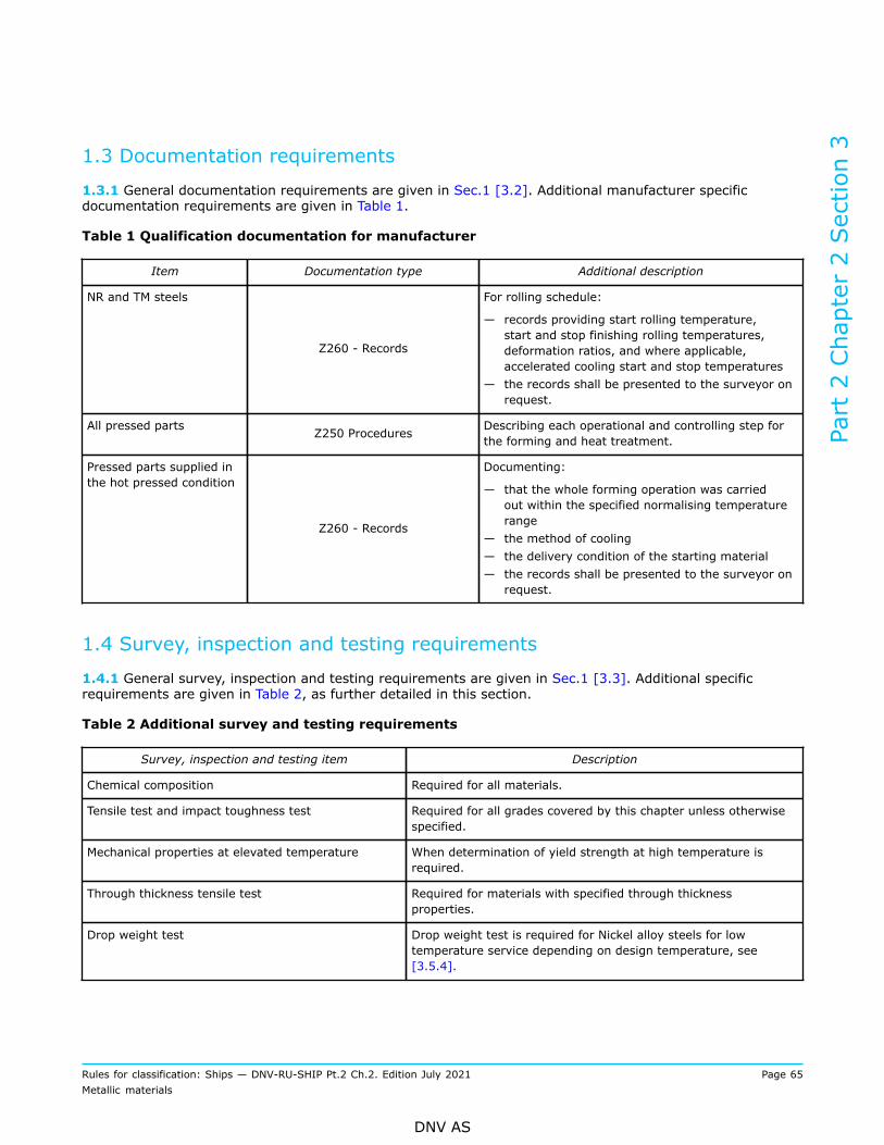
1.3 Documentation requirements
1.3.1 General documentation requirements are given in Sec.1 [3.2]. Additional manufacturer specificdocumentation requirements are given in Table 1.
Table 1 Qualification documentation for manufacturer
Item Documentation type Additional description
NR and TM steels
Z260 - Records
For rolling schedule:
— records providing start rolling temperature,start and stop finishing rolling temperatures,deformation ratios, and where applicable,accelerated cooling start and stop temperatures
— the records shall be presented to the surveyor onrequest.
All pressed parts Z250 Procedures Describing each operational and controlling step forthe forming and heat treatment.
Pressed parts supplied inthe hot pressed condition
Z260 - Records
Documenting:
— that the whole forming operation was carriedout within the specified normalising temperaturerange
— the method of cooling— the delivery condition of the starting material— the records shall be presented to the surveyor on
request.
1.4 Survey, inspection and testing requirements
1.4.1 General survey, inspection and testing requirements are given in Sec.1 [3.3]. Additional specificrequirements are given in Table 2, as further detailed in this section.
Table 2 Additional survey and testing requirements
Survey, inspection and testing item Description
Chemical composition Required for all materials.
Tensile test and impact toughness test Required for all grades covered by this chapter unless otherwisespecified.
Mechanical properties at elevated temperature When determination of yield strength at high temperature isrequired.
Through thickness tensile test Required for materials with specified through thicknessproperties.
Drop weight test Drop weight test is required for Nickel alloy steels for lowtemperature service depending on design temperature, see[3.5.4].
Part 2 Chapter 2 Section 3
Rules for classification: Ships — DNV-RU-SHIP Pt.2 Ch.2. Edition July 2021 Page 65Metallic materials
DNV AS

Survey, inspection and testing item Description
Non-destructive test (NDT) Ultrasonic test is required for steels specified with throughthickness properties, see Sec.2 [6.6].
Intercrystalline corrosion test Intercrystalline corrosion test is required for stainless steels, see[4.6.1].
1.5 Manufacture
1.5.1 All materials delivered with NV or works (W) certificate shall be made at works approved by theSociety for the type, grade and dimension of steel being supplied and for the relevant steelmaking andprocessing route, e.g. delivery condition, see Ch.1 Sec.2 [2.2.2]. Rolling mills without own steelmaking shalluse starting material supplied by works approved by the Society.
1.5.2 The steel shall be manufactured by an electric or one of the basic oxygen processes. The use of otherprocesses may be especially approved by the Society.
1.5.3 The steels shall be fully killed.
1.5.4 The reduction ratio of thickness from ingot or continuously cast slab to plate shall be at least 5 to 1unless otherwise approved by the Society.
1.5.5 It is the manufacturer’s responsibility to ensure that effective manufacture and process controls areimplemented in production. Where deviation from the controls occurs and this could produce products ofinferior quality, the manufacturer shall investigate to determine the cause and establish countermeasures toprevent its recurrence. Investigation reports to this effect shall be made available to the surveyor on request.
1.6 General for testing
1.6.1 The procedures used for all tests including retests shall be in accordance with the appropriaterequirements of Ch.1.
1.6.2 Test samples shall be taken from positions as required according to Sec.2 [2.8], unless specifiedotherwise.
1.7 Test unit
1.7.1 For testing of individual pieces, a piece shall be regarded as the rolled product from a single slab orbillet, or from a single ingot if this is rolled directly into plates, strip, sections or bars.Where plates cut from pieces are heat-treated separately, the testing shall additionally cover each heattreatment batch.
1.8 Chemical composition
1.8.1 The chemical composition of each cast shall be determined on a sample taken preferably during thepouring of the cast and shall be within the specified limits in [2] to [5]. When multiple casts are tapped into acommon ladle, the ladle analysis shall apply and be within the specified limits.
1.8.2 Elements designated as residual elements in the individual specifications shall not be intentionallyadded to the steel. The content of such elements shall be reported.
Part 2 Chapter 2 Section 3
Rules for classification: Ships — DNV-RU-SHIP Pt.2 Ch.2. Edition July 2021 Page 66Metallic materials
DNV AS

1.9 Tensile testing at ambient temperature
1.9.1 For plates, one tensile test specimen shall be taken from each piece. Where the piece is divided andheat treated in different batches, each piece in each heat treatment batch shall be tested.Where ingot casting is used, the material for testing shall represent the top of the ingot.
1.9.2 For sections, one tensile test specimen shall be taken from test units of not more than 10 tonnes. Thematerial in each test unit shall be from the same cast and of the same shape with a thickness variation of notmore than 5 mm.
1.9.3 For thermo-mechanically rolled steels processed by accelerated cooling, additional testing in thesimulated stress relieved condition may be required.
1.9.4 Test specimens for tensile testing of plates at ambient temperature shall be cut with their principalaxes transverse to the final direction of rolling.For testing of sections the test specimens shall be taken transverse or parallel to the final direction of rollingat the option of the steelmaker.
1.9.5 For carbon-manganese steel and other materials with definitive yield points, consideration shall begiven to the limitation of the yield to tensile ratio.
1.10 Tensile testing at elevated temperatures
1.10.1 At least one tensile test shall be made on material from each cast. The specimens shall be taken fromthe thickest plate from the cast.
1.10.2 The test specimens shall be cut with their principal axes transverse to the final direction of rolling.
1.10.3 When determination of lower yield strength or proof stress at high temperatures is required accordingto [2.4.4], the testing shall be carried out in compliance with ISO 6892-2.The straining rate when approaching the stress values shall be controlled to within 0.1 to 0.3% strain perminute.The intervals used for estimation of strain rate from measurements of strain shall not exceed 6 seconds.
1.10.4 When no special test temperature is specified in the order, the tests shall be carried out at 300°C.
1.11 Impact testing1.11.1 Impact test requirements
1) at least one set (i.e. 3 specimens) of impact tests shall be made for each tensile test, see [1.9]2) additional requirements when the test temperature is -50°C or lower:
— for plates one set of impact tests shall be taken for at least every 10 tonnes— for sections one set of impact tests shall be made for every 2 tonnes or part thereof, representingeach type from the same cast and with thickness variation less than 5 mm
3) except as specified for materials that shall comply with the rules Pt.5 Ch.7 (for low temperature service),impact testing is not required for materials with thickness less than 6 mm.
4) for materials that shall comply with Pt.5 Ch.7, impact testing is not required for materials with thicknessless than 3 mm, see Ch.1 Sec.3 [3.3.6]
Part 2 Chapter 2 Section 3
Rules for classification: Ships — DNV-RU-SHIP Pt.2 Ch.2. Edition July 2021 Page 67Metallic materials
DNV AS

5) the average value from each set of three impact test specimens shall comply with the appropriaterequirements in [2] to [5].
1.12 Drop weight testing
1.12.1 When drop weight test is required according to [3.5.4], one set of tests (2 test specimens) shall betaken from the thickest plate alternatively section of each cast. The extent of testing may be reduced subjectto a thorough statistical documentation.
1.13 Testing of through thickness properties
1.13.1 When steel with improved through thickness properties (Z-steel) is required or specified in the order,the materials shall be manufactured and tested in accordance with Sec.2 [6].
1.14 Corrosion testing
1.14.1 When intercrystalline corrosion testing is required, the test shall be carried out according to ISO3651-2 (ferritic, austenitic and ferritic-austenitic stainless steel), ASTM A262, Practice E, Copper - CopperSulphate - Sulphuric Acid Test (austenitic stainless steel), or to another recognised standard.
Guidance note:In case requirements for pitting or crevice corrosion resistance are specified, appropriate corrosion tests should be carried out inaccordance with an agreed standard, e.g. ASTM G48 method A.
---e-n-d---o-f---g-u-i-d-a-n-c-e---n-o-t-e---
1.15 Inspections, dimensions and tolerances
1.15.1 Surface inspection and checking of dimensions are the responsibility of the manufacturer who shallverify that the requirements concerning quality and dimensional tolerances are fulfilled prior to despatch.The manufacturer is also responsible for compliance with the general requirements concerning freedom fromharmful internal defects.Acceptance by the surveyors of material which is later found to be defective does not absolve themanufacturer from this responsibility.
1.15.2 Plates and other products shall be subjected to a thorough, visual inspection on both sides by themanufacturer to ensure freedom from defects and harmful imperfections. The surveyor may require furthernon-destructive testing, e.g. magnetic particle test, in order to verify the soundness of the material in areashe suspects that defects could be present.All plates shall be accessible to the surveyor for final survey and checking.
1.15.3 For thickness measurement the procedure shall follow the requirements given in Sec.2 [2.11].
1.15.4 No minus tolerance is permitted in the thickness of plates for pressure rating, manufactured to [2],[3] and [4].For plates, strips and wide flats not forming part of the shell and without pressure rating, and for stainlesssteels according to [4] intended for applications without pressure rating: no plate shall vary more than 0.30mm or 6% under the thickness specified, whichever is the lesser.For sections the minus tolerance shall be in accordance with a recognised national or international standard.
Part 2 Chapter 2 Section 3
Rules for classification: Ships — DNV-RU-SHIP Pt.2 Ch.2. Edition July 2021 Page 68Metallic materials
DNV AS

1.16 Surface condition and rectification of defects
1.16.1 All products shall display a workmanlike finish free from defects and imperfections which may impairtheir proper formability and use.
1.16.2 Surface defects may be removed by local grinding. The thickness beneath the ground area shallnot be less than the nominal thickness of the material. Repair of deeper defects by grinding or welding aresubject to special consideration in each separate case, and shall not be carried out unless a detailed repairprocedure is submitted and approved.
1.16.3 When defects are removed by grinding, complete elimination of the defects shall be proven bysuitable non-destructive examination of the affected area.
1.16.4 Depressions caused by grinding shall show a smooth transition to the surface.
1.17 Identification and marking
1.17.1 Every finished product shall be clearly marked by the manufacturer in at least one place with theSociety's brand and the following particulars:
a) manufacturer’s name or trade markb) steel gradec) identification number, cast number or other marking which will enable the full history of the product to
be tracedd) if required by the purchaser, his order number or other identification marke) specimen number (where necessary).
2 Steel for boilers and pressure vessels
2.1 Steel grades
2.1.1 This section specifies the requirements for rolled steel intended for use in the construction of boilers,pressure vessels, heat exchangers and other process equipment.
2.1.2 Requirements regarding carbon and carbon-manganese steels are specified for the as rolled conditionin thicknesses up to 25 mm and for the normalised, normalised rolled and thermomechanically rolledcondition in thicknesses up to 100 mm. Requirements are also given for alloy steels in thicknesses up to 100mm.
Guidance note:Several DNV grades fulfil requirements for grades according to EN 10028 as follows:NV 360S-1FN — correspond to — P235GHNV 410S-1FN — correspond to — P265GHNV 460S-1FN — correspond to — P295GHNV 510S-1FN — correspond to — P355GHNV 0.3MoS — correspond to — 16Mo3NV 1Cr0.5MoS — correspond to — 13CrMo4-5NV 2.25Cr1MoS — correspond to — 10CrMo9-10
---e-n-d---o-f---g-u-i-d-a-n-c-e---n-o-t-e---
2.1.3 The designations for carbon and carbon-manganese steel grades are built up as follows:
Part 2 Chapter 2 Section 3
Rules for classification: Ships — DNV-RU-SHIP Pt.2 Ch.2. Edition July 2021 Page 69Metallic materials
DNV AS

— the letters NV are followed by three figures which stand for the specified minimum tensile strength in N/mm2
— further, there is a single digit referring to the impact test temperature:
— the digits 0, 1 and 2 mean impact testing at +20°C, 0°C and –20°C respectively
— the suffix letters are symbolizing the heat treatment and fine grain treatment:
— A means As rolled— N means Normalised— NR means Normalised Rolled— TM means Thermo Mechanically rolled— QT means Quenched and Tempered— F means Fine grain treated.
Guidance note:Example: NV 360−1FN means a steel grade with specified minimum tensile strength 360 N/mm2 impact tested at 0°C (1), finegrain treated (F) and normalised (N).
---e-n-d---o-f---g-u-i-d-a-n-c-e---n-o-t-e---
The tables of requirements lists the normalised (N) grades. For steels having another delivery condition, therequirements given for delivery condition N apply.
2.2 Chemical composition
2.2.1 The chemical composition shall satisfy the requirements specified in Table 3 for carbon and carbon-manganese steels and in Table 4 for alloy steels.
2.2.2 The content of all elements given in the specification including grain refining elements shall bedetermined and entered on the certificate. The content shall be in accordance with the composition qualifiedthrough manufacturer approval. The content of residual elements shall be checked by random tests asagreed with the surveyor.
2.2.3 Where Al is replaced by other grain refining elements and unless otherwise approved, the contents ofsuch elements shall be:
— Nb, minimum 0.02%, maximum 0.05%— V, minimum 0.05%, maximum 0.10%.
See also [2.2.2].
2.2.4 For carbon and carbon-manganese steels, the carbon equivalent shall be calculated as per Ch.1 Sec.2[3.3].
2.3 Condition of supply and heat treatment
2.3.1 The materials shall be supplied in the heat treatment conditions stated in Table 10, except forapplications where as rolled condition is explicitly permitted, and except that materials which shall beheat-treated after hot or cold forming may be supplied in the as rolled condition subject to the customer'sconsent and in compliance with the Society rules. In such cases heat treatment and subsequent mechanicaltesting shall be carried out after forming, and the results shall fulfil the requirements for the appropriateheat treatment condition. Nevertheless, the starting material in the as rolled condition shall be subjectedto testing in accordance with the certification requirements, e.g. at the steel mill, before forming, and theresults shall fulfil the requirements for as rolled condition. Further requirements for hot and cold forming ofpressed parts are given in subsection [5].
Part 2 Chapter 2 Section 3
Rules for classification: Ships — DNV-RU-SHIP Pt.2 Ch.2. Edition July 2021 Page 70Metallic materials
DNV AS

2.4 Mechanical properties
2.4.1 Sampling: general requirements for sampling are given in [1.6] to [1.13].For sheets made from hot rolled wide strip coils, at least one specimen shall be sampled from the outer endof each coil.
2.4.2 Acceptance criteria: the mechanical properties of the material shall comply with the requirementsspecified in the following tables:
— Table 5 carbon and carbon-manganese steels, as rolled— Table 6 carbon and carbon-manganese steels, normalised, normalised rolled or thermo-mechanicallyrolled
— Table 7 alloy steels.The values for tensile strength, yield strength and elongation specified in the tables refer to testing at roomtemperature.
2.4.3 Formability of fire tubes: plates to be manufactured into fire tubes shall exhibit adequate formability,i.e. elongation A ≥ 20% at 20°C.
2.4.4 Tensile properties at elevated temperature: values for lower yield strength or 0.2% proof stress atelevated temperatures are given in Table 8. The values are intended for design purposes and verification isnot required.High temperature tensile properties for materials produced in accordance with a recognised standard. If thematerial is produced in compliance with a recognised standard where the lower yield strength or 0.2% proofstress at high temperatures is higher than stated in Table 8, these higher values will be accepted, providedthat tensile tests at high temperatures, in compliance with [1.10], are carried out with satisfactory results.The tensile test at high temperatures may be dispensed with if the steelmaker can demonstrate to thesatisfaction of the Society that the specified minimum mechanical properties at high temperatures can beconsistently obtained in the running production.
2.4.5 Stress to rupture: estimated average values for stress to rupture in 10 000, 100 000 and 200 000hours are given in Table 9 for design purposes.
Table 3 Carbon and carbon-manganese steels for boilers and pressure vessels. Chemicalcomposition
Chemical composition 1, 2), [%]
Grade C
max.Si Mn
P
max.
S
max.Al 3)
N
max.
NV 360-0A, -0N 0.17 ≤ 0.35 0.40 to 1.00 4) 0.035 0.030 ≥ 0.015 0.009 5)
NV 360-1FN 0.17 ≤ 0.35 0.40 to 1.00 4) 0.035 0.030 0.020 to 0.085 6) 0.012
NV 360S-1FN 0.16 ≤ 0.35 0.60 to 1.20 0.025 0.010 > 0.020 0.012 7)
NV 410-0A, -0N 0.20 ≤ 0.35 0.50 to 1.30 0.035 0.030 ≥ 0.015 0.009 5)
NV 410-1FN 0.20 ≤ 0.35 0.50 to 1.30 0.035 0.030 0.020 to 0.085 6) 0.012
NV 410S-1FN 0.20 ≤ 0.40 0.80 to 1.40 0.025 0.010 ≥ 0.020 0.012 7)
NV 460-0A, -0N 0.20 ≤ 0.40 0.60 to 1.40 8) 0.035 0.030 ≥ 0.015 0.009 5)
NV 460-1FN 0.20 9) ≤ 0.40 0.60 to 1.40 8) 0.035 0.030 0.020 to 0.085 6) 0.012
Part 2 Chapter 2 Section 3
Rules for classification: Ships — DNV-RU-SHIP Pt.2 Ch.2. Edition July 2021 Page 71Metallic materials
DNV AS
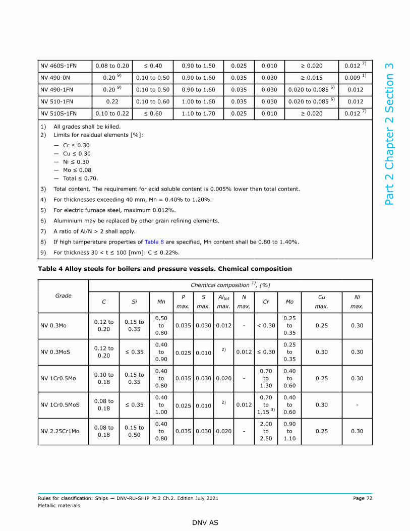
NV 460S-1FN 0.08 to 0.20 ≤ 0.40 0.90 to 1.50 0.025 0.010 ≥ 0.020 0.012 7)
NV 490-0N 0.20 9) 0.10 to 0.50 0.90 to 1.60 0.035 0.030 ≥ 0.015 0.009 1)
NV 490-1FN 0.20 9) 0.10 to 0.50 0.90 to 1.60 0.035 0.030 0.020 to 0.085 6) 0.012
NV 510-1FN 0.22 0.10 to 0.60 1.00 to 1.60 0.035 0.030 0.020 to 0.085 6) 0.012
NV 510S-1FN 0.10 to 0.22 ≤ 0.60 1.10 to 1.70 0.025 0.010 ≥ 0.020 0.012 7)
1) All grades shall be killed.2) Limits for residual elements [%]:
— Cr ≤ 0.30— Cu ≤ 0.30— Ni ≤ 0.30— Mo ≤ 0.08— Total ≤ 0.70.
3) Total content. The requirement for acid soluble content is 0.005% lower than total content.
4) For thicknesses exceeding 40 mm, Mn = 0.40% to 1.20%.
5) For electric furnace steel, maximum 0.012%.
6) Aluminium may be replaced by other grain refining elements.
7) A ratio of Al/N > 2 shall apply.
8) If high temperature properties of Table 8 are specified, Mn content shall be 0.80 to 1.40%.
9) For thickness 30 < t ≤ 100 [mm]: C ≤ 0.22%.
Table 4 Alloy steels for boilers and pressure vessels. Chemical composition
Chemical composition 1), [%]
GradeC Si Mn
P
max.
S
max.
Altotmax.
N
max.Cr Mo
Cu
max.
Ni
max.
NV 0.3Mo 0.12 to0.20
0.15 to0.35
0.50to0.80
0.035 0.030 0.012 - < 0.300.25to0.35
0.25 0.30
NV 0.3MoS 0.12 to0.20 ≤ 0.35
0.40to0.90
0.025 0.0102) 0.012 ≤ 0.30
0.25to0.35
0.30 0.30
NV 1Cr0.5Mo 0.10 to0.18
0.15 to0.35
0.40to0.80
0.035 0.030 0.020 -0.70to1.30
0.40to0.60
0.25 0.30
NV 1Cr0.5MoS 0.08 to0.18 ≤ 0.35
0.40to1.00
0.025 0.0102) 0.012
0.70to
1.15 3)
0.40to0.60
0.30 -
NV 2.25Cr1Mo 0.08 to0.18
0.15 to0.50
0.40to0.80
0.035 0.030 0.020 -2.00to2.50
0.90to1.10
0.25 0.30
Part 2 Chapter 2 Section 3
Rules for classification: Ships — DNV-RU-SHIP Pt.2 Ch.2. Edition July 2021 Page 72Metallic materials
DNV AS

NV 2.25Cr1MoS 0.08 to0.14 ≤ 0.50
0.40to0.80
0.020 0.0102) 0.012
2.00to2.50
0.90to1.10
0.30 -
1) All grades shall be killed.2) The Al content of the cast shall be determined and given in the inspection document.3) If resistance to pressurized hydrogen is of importance, a minimum content of 0.80% Cr may be agreed upon at the
time of enquiry and order.
Table 5 Carbon and carbon-manganese steels for boilers and pressure vessels, as rolled condition.Mechanical properties
Yield strength, ReH orRp0.2 [N/mm
2] minimumfor thickness, [mm]
Charpy V-notch, minimum average
GradeTensile
strength Rm[N/mm2]
t ≤ 16 16 < t ≤ 25
ElongationA5 [%]minimum Test
temperature
[°C]
Transverse
[J]
Longitudinal
[J]
NV 360-0A 360 to 480 205 195 26 20 27 39
NV 410-0A 410 to 530 235 225 24 20 27 39
NV 460-0A 460 to 580 285 255 22 20 27 39
Table 6 Carbon and carbon-manganese steels for boilers and pressure vessels, normalised ornormalised rolled condition. Mechanical properties
Yield strength, ReH orRp0.2 [N/mm
2] minimumfor thickness, [mm]
Charpy V-notch, minimum average
Grade
TensilestrengthRm [N/mm2] t ≤
16
16< t≤ 40
40< t≤ 63
63 <t ≤100
ElongationA5,[%]minimum Test
temperature
[°C]
Transverse
[J]
Longitudinal
[J]
NV 360-0N 360 to 480 205 195 185 175 26 1) 20 27 39
NV 360-1FN 360 to 480 235 215 195 2) 26 1) 0 27 39
NV 360S-1FN 360 to 480 235 225 2154)
2005) 24 0 34 48
NV 410-0N 410 to 530 235 225 215 205 24 1) 20 27 39
NV 410-1FN 410 to 530 265 245 235 2) 24 1) 0 27 39
NV 410S-1FN 410 to 530 265 255 2454)
2155) 22 0 34 48
NV 460-0N 460 to 580 285 255 245 235 22 1) 20 27 39
NV 460-1FN 460 to 580 295 285 275 2) 22 1) 0 27 39
NV 460S-1FN 460 to 580 295 290 2854)
2605) 21 0 34 48
NV 490-0N 490 to 610 305 275 265 255 21 1) 20 29 41
Part 2 Chapter 2 Section 3
Rules for classification: Ships — DNV-RU-SHIP Pt.2 Ch.2. Edition July 2021 Page 73Metallic materials
DNV AS

NV 490-1FN 490 to 610 315 315 305 2) 21 0 29 41
NV 510-1FN 510 to650 3) 355 345 335 315 20 0 29 41
510 to 650 355 345 3354) -
NV 510S-1FN
490 to 630 - - - 3155)
20 0 34 48
1) For thicknesses 40 < t ≤ 63 [mm], the minimum value is 1 unit lower and for thicknesses 63 < t ≤ 100 [mm], 2units lower.
2) For thicknesses in the range 63 < t ≤ 100 [mm], the value specified for the thickness range 40 < t ≤ 63 [mm] shallbe lowered by 1% for each 5 mm of thickness over 63 mm.
3) For thicknesses 63 < t ≤ 100 [mm]: Rm = 490 to 630 [N/mm2].
4) For thickness 40 < t ≤ 60 [mm].5) For thickness 60 < t ≤ 100 [mm].
Table 7 Alloy steels for boilers and pressure vessels. Mechanical properties
Yield strength ReH or Rp0.2[N/mm2] minimum forthickness, [mm]
Charpy V-notch, minimum average
GradeTensilestrength Rm[N/mm2] t ≤
16
16< t≤ 40
40< t≤ 63
63 < t≤ 100
ElongationA5 [%]min. Test
temperature[°C]
Transverse
[J]Longitudinal
[J]
NV 0.3Mo 440 to 590 260 250 250 2) 24 1) 20 27 39
440 to 590 275 270 2603) -
NV 0.3MoS
430 to 580 - - - 240 4)22 20 31 44
NV 1Cr0.5Mo 470 to 620 305 305 305 2) 20 1) 20 29 43
300 290 2903) - 31 44
NV 1Cr0.5MoS 450 to 600
- - - 270 4)19 20
27 38
NV 2.25Cr1Mo 480 to 630 275 265 265 2) 18 1) 20 27 39
480 to 630 310 300 2903) - 18 31 44
NV 2.25Cr1MoS
470 to 620 - - - 280 4) 17
20
27 38
1) For thicknesses 40 < t ≤ 63 [mm], the minimum value is 1 unit lower and for thicknesses 63 < t ≤ 100 [mm], 2units lower.
2) For thicknesses in the range 63 < t ≤ 100 [mm], the value specified for the thickness range 40 < t ≤ 63 [mm] shallbe lowered by 1% for each 5 mm of thickness over 63 mm.
3) For thicknesses 63 < t ≤ 100 [mm]: Rm = 490 to 630 [N/mm2].
4) For thickness 40 < t ≤ 60 [mm].5) For thickness 60 < t ≤ 100 [mm].
Part 2 Chapter 2 Section 3
Rules for classification: Ships — DNV-RU-SHIP Pt.2 Ch.2. Edition July 2021 Page 74Metallic materials
DNV AS
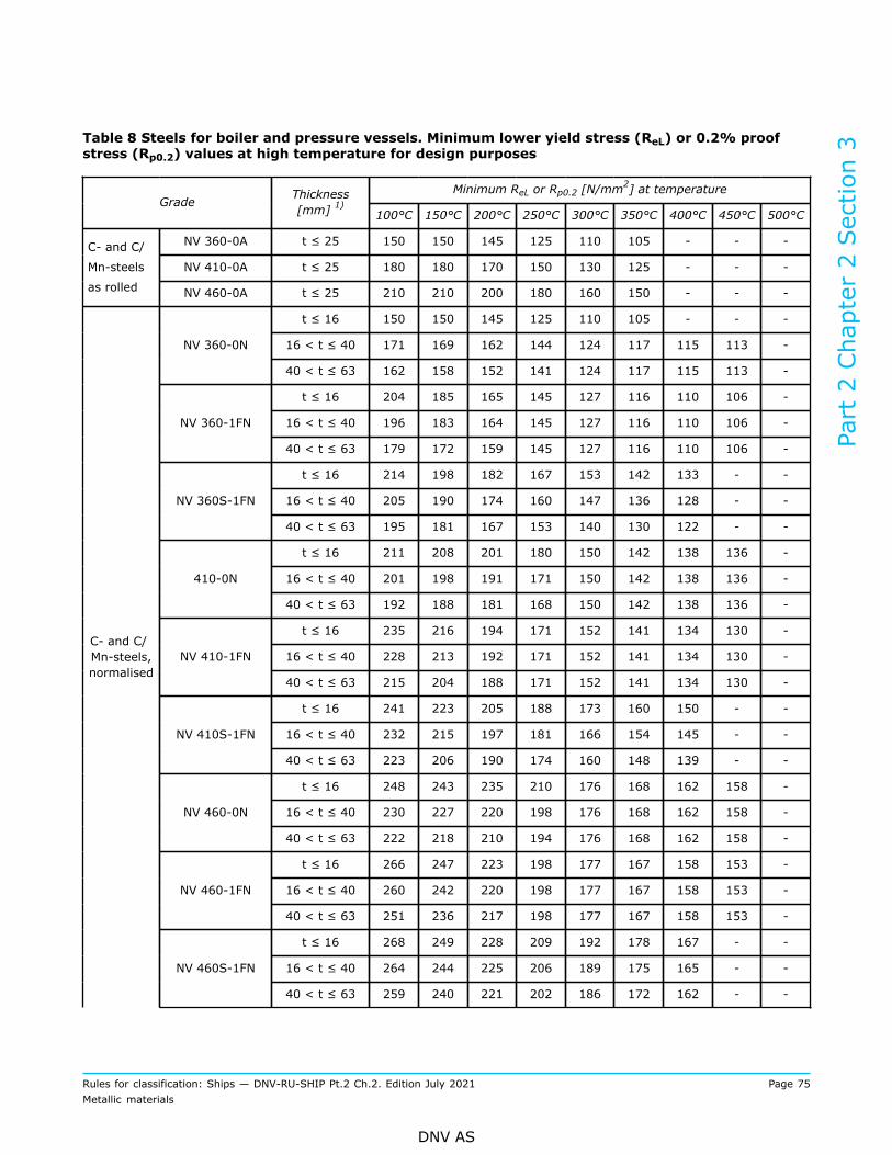
Table 8 Steels for boiler and pressure vessels. Minimum lower yield stress (ReL) or 0.2% proofstress (Rp0.2) values at high temperature for design purposes
Minimum ReL or Rp0.2 [N/mm2] at temperature
Grade Thickness[mm] 1) 100°C 150°C 200°C 250°C 300°C 350°C 400°C 450°C 500°C
NV 360-0A t ≤ 25 150 150 145 125 110 105 - - -
NV 410-0A t ≤ 25 180 180 170 150 130 125 - - -
C- and C/
Mn-steels
as rolled NV 460-0A t ≤ 25 210 210 200 180 160 150 - - -
t ≤ 16 150 150 145 125 110 105 - - -
16 < t ≤ 40 171 169 162 144 124 117 115 113 -NV 360-0N
40 < t ≤ 63 162 158 152 141 124 117 115 113 -
t ≤ 16 204 185 165 145 127 116 110 106 -
16 < t ≤ 40 196 183 164 145 127 116 110 106 -NV 360-1FN
40 < t ≤ 63 179 172 159 145 127 116 110 106 -
t ≤ 16 214 198 182 167 153 142 133 - -
16 < t ≤ 40 205 190 174 160 147 136 128 - -NV 360S-1FN
40 < t ≤ 63 195 181 167 153 140 130 122 - -
t ≤ 16 211 208 201 180 150 142 138 136 -
16 < t ≤ 40 201 198 191 171 150 142 138 136 -410-0N
40 < t ≤ 63 192 188 181 168 150 142 138 136 -
t ≤ 16 235 216 194 171 152 141 134 130 -
16 < t ≤ 40 228 213 192 171 152 141 134 130 -NV 410-1FN
40 < t ≤ 63 215 204 188 171 152 141 134 130 -
t ≤ 16 241 223 205 188 173 160 150 - -
16 < t ≤ 40 232 215 197 181 166 154 145 - -NV 410S-1FN
40 < t ≤ 63 223 206 190 174 160 148 139 - -
t ≤ 16 248 243 235 210 176 168 162 158 -
16 < t ≤ 40 230 227 220 198 176 168 162 158 -NV 460-0N
40 < t ≤ 63 222 218 210 194 176 168 162 158 -
t ≤ 16 266 247 223 198 177 167 158 153 -
16 < t ≤ 40 260 242 220 198 177 167 158 153 -NV 460-1FN
40 < t ≤ 63 251 236 217 198 177 167 158 153 -
t ≤ 16 268 249 228 209 192 178 167 - -
16 < t ≤ 40 264 244 225 206 189 175 165 - -
C- and C/Mn-steels,normalised
NV 460S-1FN
40 < t ≤ 63 259 240 221 202 186 172 162 - -
Part 2 Chapter 2 Section 3
Rules for classification: Ships — DNV-RU-SHIP Pt.2 Ch.2. Edition July 2021 Page 75Metallic materials
DNV AS

t ≤ 16 270 264 255 228 192 183 177 172 -
16 < t ≤ 40 248 245 237 214 192 183 177 172 -NV 490-0N
40 < t ≤ 63 240 236 227 210 192 183 177 172 -
t ≤ 16 284 265 240 213 192 182 173 168 -
16 < t ≤ 40 279 260 237 213 192 182 173 168 -NV 490-1FN
40 < t ≤ 63 272 256 234 213 192 182 173 168 -
NV 510-1FN t ≤ 63 - - 265 245 225 205 175 155 -
t ≤ 16 323 299 275 252 232 214 202 - -
16 < t ≤ 40 314 291 267 245 225 208 196 - -NV 510S-1FN
40 < t ≤ 63 305 282 259 238 219 202 190 - -
NV 0.3Mo t ≤ 63 237 232 218 200 167 153 148 143 139
t ≤ 16 264 250 233 213 194 175 159 147 141
16 < t ≤ 40 259 245 226 209 190 172 156 145 139
40 < t ≤ 60 250 236 220 202 183 165 150 139 134NV 0.3MoS
60 < t ≤ 100 230 218 203 186 169 153 139 129 123
NV 1Cr0.5Mo t ≤ 63 270 259 248 237 216 203 199 194 188
t ≤ 16 285 269 252 234 216 200 186 175 164
16 < t ≤ 40 275 260 243 226 209 194 180 169 159NV 1Cr0.5MoS
40 < t ≤ 60 256 242 227 210 195 180 168 157 148
NV 2.25Cr1Mo t ≤ 63 249 241 233 224 219 212 207 194 180
t ≤ 16 266 254 248 243 236 225 212 197 185
16 < t ≤ 40 257 246 240 235 228 218 205 191 179
40 < t ≤ 60 249 238 232 227 221 211 198 185 173
Alloy steels
NV 2.25Cr1MoS
60 < t ≤ 100 240 230 224 220 213 204 191 178 167
1) Unless values for thickness range 63 < t ≤ 100 [mm] are specified, the values specified for thickness range 40 < t ≤63 [mm] are lowered by 1% for each 5 mm of thickness over 63 mm.
Part 2 Chapter 2 Section 3
Rules for classification: Ships — DNV-RU-SHIP Pt.2 Ch.2. Edition July 2021 Page 76Metallic materials
DNV AS

Table 9 Estimated average stress to rupture values in 10 000, 100 000 and 200 000 hours fordesign purposes
Stress to rupture, [N/mm2] for steel grades
NV 360-0N
NV 360-1FN
NV360S-1FN
NV 410-0N
NV 410-1FN
NV410S-1FN
NV 460-0N
NV 460-1FN
NV 460S-1FN
NV 490-0N
NV 490-1FN
NV 510-1FN
NV 510S-1FN
NV 0.3Mo
NV 0.3MoSNV 1Cr0.5Mo NV
1Cr0.5MoS NV 2.25Cr1Mo NV2.25Cr1MoS
Testtemperature
[°C]
100khours
200khours
100khours
200khours
100khours
200khours
100khours
200khours
10khours
100khours
100khours
200khours
100khours
200khours
380 165 145 227 206
390 148 129 203 181
400 132 115 179 157
410 118 101 157 135
420 103 89 136 115
430 91 78 117 97
440 79 67 100 82
450 69 57 85 70 239 217 285 260 221 203 221 201
460 59 48 73 60 208 188 251 226 204 186 205 186
470 50 40 63 52 178 159 220 195 186 169 188 169
480 42 33 55 44 148 130 210 180 190 167 170 152 170 152
490 47 37 123 105 177 148 163 139 153 135 152 136
500 41 30 101 84 146 122 137 115 137 119 135 120
510 81 69 121 99 116 96 122 103 118 105
520 66 55 99 79 94 76 107 89 103 91
530 53 45 81 64 78 62 93 77 90 79
540 67 52 61 50 79 68 78 68
550 54 42 49 39 69 58 68 58
560 43 34 40 32 59 50 58 50
570 35 33 26 51 43 51 43
580 44 44 37
590 38 32
600 34 28
Part 2 Chapter 2 Section 3
Rules for classification: Ships — DNV-RU-SHIP Pt.2 Ch.2. Edition July 2021 Page 77Metallic materials
DNV AS

Table 10 Heat treatment of steel for boilers and pressure vessels
Grade Heat treatment or condition of supply
NV 360-0A
NV 410-0A
NV 460-0A
As rolled 1)
NV 360-0N, -1FN
NV 410-0N, -1FN
NV 460-0N, -1FN
NV 490-0N, -1FN
NV 510-1FN
Normalised / normalised rolled / thermo-mechanically rolled
NV 360-1FN or 360S-1FN
NV 410-1FN or 410S-1FN
NV 490-1FN or 490S-1FN
NV 510-1FN or 510S-1FN
Normalised / normalised and tempered
NV 0.3Mo Normalised
NV 0.3MoS Normalised / normalised and tempered
NV 1Cr0.5Mo
NV 2.25Cr1MoNormalised and tempered
NV 2.25Cr1MoS Normalised and tempered 2) / quenched and tempered 3)
1) See [2.3.1], as rolled condition permitted for starting material only, or where explicitly permitted by the rules forspecific applications.
2) Applicable for thickness t ≤ 100 mm.3) Applicable for thickness 60 < t ≤ 100 [mm].
3 Steel for low temperature service
3.1 Scope
3.1.1 This section specifies the requirements for rolled steel intended for use at low temperatures, e.g. forthe fabrication of cargo tanks and process pressure vessels for carrying liquefied gases.
3.2 Steel grades
3.2.1 Steel grades covered by this section: requirements are specified for the following steels with specifiedlow temperature properties, for thickness up to 40 mm:
— fine grained carbon-manganese structural steels— nickel alloy steels— austenitic manganese alloy steels.
Steel grades with thickness larger than 40 mm are subject to case by case approval.
3.2.2 Other steel grades: for acceptance and approval of steel grades based on other standards, see Ch.1Sec.1 [3.4].
Part 2 Chapter 2 Section 3
Rules for classification: Ships — DNV-RU-SHIP Pt.2 Ch.2. Edition July 2021 Page 78Metallic materials
DNV AS

Guidance note:As an example, steel grades based on EN 10028-3/4/5/6 needs additional requirements to chemical composition and impacttoughness in order to comply with the requirements for liquefied gas carriers in Pt.5 Ch.7 Sec.6.
---e-n-d---o-f---g-u-i-d-a-n-c-e---n-o-t-e---
3.2.3 High strength carbon manganese steels: carbon manganese steels with specified minimum yieldstrength SMYS > 335 MPa complying with a recognized standard, e.g. EN 10028, may be considered foracceptance and approval. Note that for steels for liquefied gas carriers, a SMYS ≤ 410 MPa is required unlessotherwise approved.
3.2.4 Austenitic stainless steels: requirements for austenitic stainless steels applied for low temperatureservice are given in [4].
3.2.5 Steels for liquefied gas carriers: in addition to the requirements given in this section, steels forliquefied gas carriers shall satisfy the requirements given in Pt.5 Ch.7 Sec.6 (e.g. with respect to deliverycondition, deoxidation practice, fine grain treatment, testing extent, specified minimum yield strength andimpact toughness, chemical composition, etc.).
3.2.6 Minimum design temperatures: the minimum design temperatures for the specified grades are given inTable 13 and Table 14.
3.3 Chemical composition
3.3.1 The chemical composition shall satisfy the requirements specified in Table 11 for carbon manganesesteels and in Table 12 for nickel alloy steels and austenitic manganese alloy steels.For materials complying with recognized standards, see [3.2.2], the chemical composition shall satisfy therequirements of the relevant standard and grade.
3.3.2 The content of all elements given in the specifications including grain refining elements shall bedetermined and entered on the certificate. The content of residual elements shall be checked by random testsas agreed upon with the surveyor.
3.3.3 The steels shall be aluminium and fine grain treated.
3.3.4 For carbon and carbon-manganese steels, the carbon equivalent Ceq shall be calculated from the ladleanalysis using the formula given in Ch.1 Sec.2 [3.3], when applicable.For evaluation of the weldability of high-strength steels see [3.2.3], sensitivity to cold cracking Pcm shall bedetermined as per Ch.1 Sec.2 [3.3].
Table 11 Carbon-manganese steels for low temperature service. Chemical composition
Chemical composition, [%]
Grade C 1)
maximumSi Mn
S
maximum
P
maximum
Al 2)
total
N
maximumRequirements forother elementsPart 2 Chapter 2 Section 3
Rules for classification: Ships — DNV-RU-SHIP Pt.2 Ch.2. Edition July 2021 Page 79Metallic materials
DNV AS
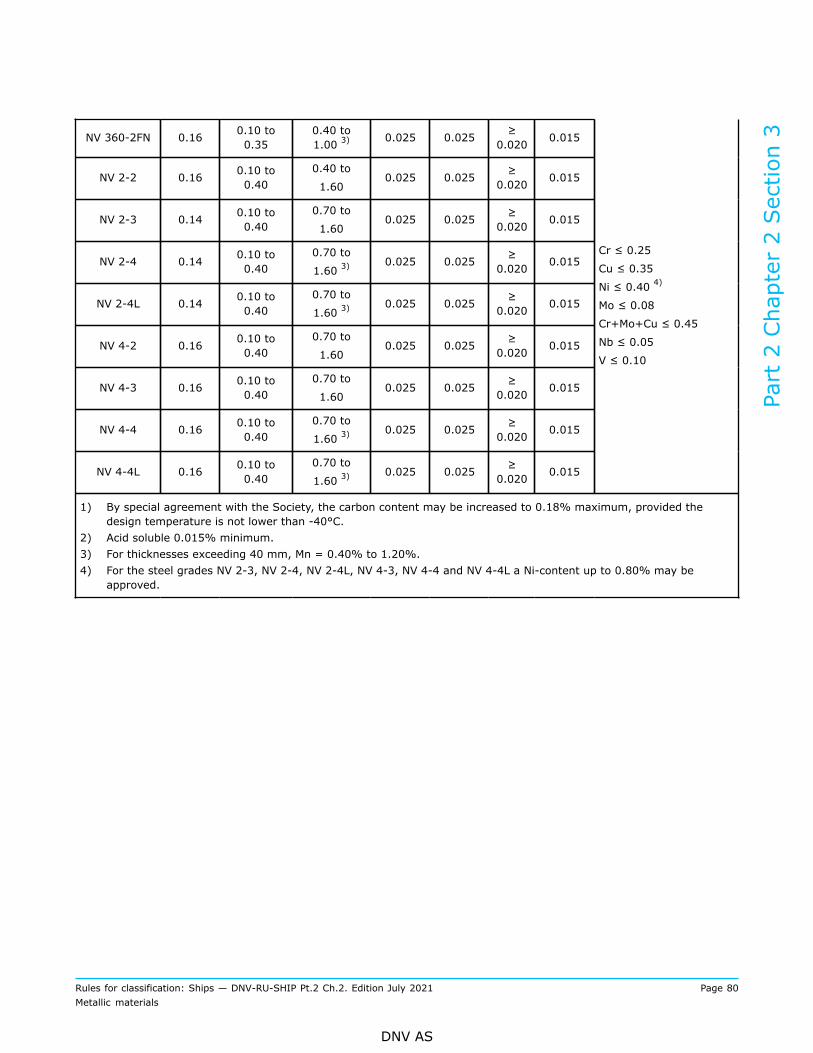
NV 360-2FN 0.16 0.10 to0.35
0.40 to1.00 3) 0.025 0.025 ≥
0.020 0.015
NV 2-2 0.16 0.10 to0.40
0.40 to
1.600.025 0.025 ≥
0.020 0.015
NV 2-3 0.14 0.10 to0.40
0.70 to
1.600.025 0.025 ≥
0.020 0.015
NV 2-4 0.14 0.10 to0.40
0.70 to
1.60 3)0.025 0.025 ≥
0.020 0.015
NV 2-4L 0.14 0.10 to0.40
0.70 to
1.60 3)0.025 0.025 ≥
0.020 0.015
NV 4-2 0.16 0.10 to0.40
0.70 to
1.600.025 0.025 ≥
0.020 0.015
NV 4-3 0.16 0.10 to0.40
0.70 to
1.600.025 0.025 ≥
0.020 0.015
NV 4-4 0.16 0.10 to0.40
0.70 to
1.60 3)0.025 0.025 ≥
0.020 0.015
NV 4-4L 0.16 0.10 to0.40
0.70 to
1.60 3)0.025 0.025 ≥
0.020 0.015
Cr ≤ 0.25
Cu ≤ 0.35
Ni ≤ 0.40 4)
Mo ≤ 0.08
Cr+Mo+Cu ≤ 0.45
Nb ≤ 0.05
V ≤ 0.10
1) By special agreement with the Society, the carbon content may be increased to 0.18% maximum, provided thedesign temperature is not lower than -40°C.
2) Acid soluble 0.015% minimum.3) For thicknesses exceeding 40 mm, Mn = 0.40% to 1.20%.4) For the steel grades NV 2-3, NV 2-4, NV 2-4L, NV 4-3, NV 4-4 and NV 4-4L a Ni-content up to 0.80% may be
approved.
Part 2 Chapter 2 Section 3
Rules for classification: Ships — DNV-RU-SHIP Pt.2 Ch.2. Edition July 2021 Page 80Metallic materials
DNV AS

Table 12 Nickel alloy steels and austenitic manganese alloy steels for low temperature service.Chemical composition
Chemical composition, [%]
Grade C
maximum6) Si MnS
maximum
P
maximumNi Altot
NV 0.5Ni/a 1) 0.14 0.10 to 0.50 0.70 to 1.50 0.010 0.025 0.15 2) to 0.80 ≥ 0.020
NV 0.5Ni/b 1) 0.16 0.10 to 0.50 0.85 to 1.70 0.010 0.025 0.15 2) to 0.85 ≥ 0.020
NV 1.5Ni 0.14 0.10 to 0.35 0.30 to 1.50 0.025 0.025 1.30 to 1.70 ≥ 0.020
NV 2.25Ni 0.13 0.10 to 0.35 0.30 to 1.50 0.025 0.025 2.00 to 2.50 ≥ 0.020
NV 3.5Ni 0.12 0.10 to 0.35 0.30 to 0.70 0.025 0.025 3.25 to 3.75 ≥ 0.020
NV 5Ni/a 0.12 0.10 to 0.35 0.30 to 0.80 0.025 0.025 4.70 to 5.30 ≥ 0.020
NV 5Ni/b3) 0.13 0.20 to 0.40 0.30 to 0.60 0.025 0.025 4.80 to 5.20 0.02 to 0.12
NV 5Ni/c4) 0.13 0.15 to 0.30 0.90 to 1.50 0.010 0.020 5.00 to 6.00 0.02 to 0.06
NV 9Ni/a 0.10 0.10 to 0.35 0.30 to 0.90 0.025 0.025 8.50 to 10.0 ≥ 0.010
NV 9Ni/b 0.13 0.15 to 0.40 0.90 0.015 0.015 8.50 to 9.50 ≥ 0.025
NV Mn 4005) 0.35 to 0.55 0.10 to 0.50 22.50to 25.50 0.010 0.030 - -
1) Further compositional requirements:
— Cr ≤ 0.25%— Mo ≤ 0.08%— Cu ≤ 0.35%— Nb ≤ 0.05%— V ≤ 0.05%— Cr+Cu+Mo ≤ 0.50%.
2) For thicknesses ≥ 40 mm; Ni ≥ 0.30%.
3) 0.20 ≤ Mo ≤ 0.35; N ≤ 0.020.
4) 0.10 ≤ Mo ≤ 0.30; N ≤ 0.010.
5) Further compositional requirements:
— 3.00% ≤ Cr ≤ 4.00%— B ≤ 0.005%— N ≤ 0.050%.
6) Except NV Mn 400.
3.4 Condition of supply and heat treatment
3.4.1 The steels shall be supplied in the heat treatment conditions stated in Table 13.
3.4.2 Quenched and tempered, normalised rolled and thermo-mechanically treated steel grades shall begiven the suffix QT, NR, and TM respectively.
Part 2 Chapter 2 Section 3
Rules for classification: Ships — DNV-RU-SHIP Pt.2 Ch.2. Edition July 2021 Page 81Metallic materials
DNV AS

3.4.3 Steels with delivery condition TM shall not be used where hot forming or normalising will be carriedout.
Guidance note:Hot forming or normalising of thermo-mechanically treated steels may result in considerable reduction of tensile strength and yieldstrength.
---e-n-d---o-f---g-u-i-d-a-n-c-e---n-o-t-e---
3.4.4 For materials complying with recognized standards, see [3.2.2], the condition of supply shall satisfythe requirements of the relevant standard and grade, unless otherwise approved.
Table 13 Heat treatment of steels for low temperature service
Grade Heat treatment/condition of supply
NV 360-2FN
NV 2-2
NV 2-3
NV 2-4
NV 2-4L
NV 4-2
NV 4-3
NV 4-4
NV 4-4L
Plates: normalised 1).
Sections: normalised, thermo-mechanically treated or normalised rolled 2).
NV 0.5Ni/a
NV 0.5Ni/b
NV 1.5Ni
NV 2.25Ni
NV 3.5Ni
NV 5Ni/a
NV 5Ni/b
NV 5Ni/c
Normalised, normalised and tempered or quenched and tempered.
Thermo-mechanically treated or other heat treatments upon special approval.
NV 5Ni/b and NV 5Ni/c: heat treatment as per ASTM A645.
NV 9Ni/a
NV 9Ni/b
Double normalised and tempered or quenched and tempered 3).
NV 9Ni/b: double normalised and tempered as per ASTM A353.
NV Mn 400 Hot rolled and controlled cooling.
1) Other heat treating processes, e.g. quenching and tempering or thermo-mechanical controlled processing may beapproved, see [3.4.3].
2) See [3.4.3].3) Quenching and tempering will normally be required for thicknesses above 30 mm.
3.5 Mechanical properties
3.5.1 The mechanical properties of the material shall comply with the requirements specified in the followingtables:
— Table 14 — carbon-manganese steels— Table 15 — nickel alloy steels.
Part 2 Chapter 2 Section 3
Rules for classification: Ships — DNV-RU-SHIP Pt.2 Ch.2. Edition July 2021 Page 82Metallic materials
DNV AS

3.5.2 The values for tensile strength, yield strength and elongation specified in the tables refer to testing atroom temperature.For materials complying with recognized standards, see [3.2.2], the mechanical properties shall satisfy therequirements of the relevant standard and grade.
3.5.3 Requirements for the Charpy V-notch toughness tests are given in Table 14 and Table 15, and applyunless otherwise specified in the referring rules. The testing and requirements for specimens smaller than 5mm in size shall be in accordance with recognized standards, see Ch.1 Sec.3 [3.3.6].
3.5.4 Drop weight test shall be carried out for plates and sections of nickel alloy steels with thickness 13 mmand more in the following cases:
— NV 2.25Ni when intended for design temperature below –65°C— NV 3.5Ni when intended for design temperature below –80°C— NV 5Ni when intended for design temperature below –90°C.
The test specimens shall display a no break performance when tested 5°C below the design temperature. Seealso [1.12].
Table 14 Carbon-manganese steels for low temperature service. Mechanical properties 1)
Yieldstrength
[N/mm2)]
minimum forthickness,[mm]
Charpy V-notch impact energy, minimum average 2)
GradeTensilestrength
[N/mm2]
≤ 16> 16
≤ 40
ElongationA5 [%]minimum
Thickness
[mm]
Test
temperature
[°C] 3, 4, 5)
Transverse
[J]
Longitudinal
[J]
Min. designtemperature,
[°C]
NV 360-2FN 360 to480 235 215 26
t ≤ 25
25 < t ≤ 30
30 < t ≤ 35
35 < t ≤ 40
- 20
- 25
- 30
- 35
27 41 -15
NV 2-2 400 to490 265 255 24
t ≤ 25
25 < t ≤ 30
30 < t ≤ 35
35 < t ≤ 40
- 20
- 25
- 30
- 35
27 41 -15
NV 2-3 400 to490 265 255 24
t ≤ 25
25 < t ≤ 30
30 < t ≤ 35
35 < t ≤ 40
- 40
- 45
- 50
- 55
27 41 -35
NV 2-4 400 to490 265 255 24
t ≤ 25
25 < t ≤ 30
30 < t ≤ 35
35 < t ≤ 40
- 55
- 60
- 65
- 70
27 41 -50
Part 2 Chapter 2 Section 3
Rules for classification: Ships — DNV-RU-SHIP Pt.2 Ch.2. Edition July 2021 Page 83Metallic materials
DNV AS

NV 2-4L 400 to490 265 255 24
t ≤ 25
25 < t ≤ 30
30 < t ≤ 35
35 < t ≤ 40
- 60
- 65
- 70
- 75
27 41 -55
NV 4-2 490 to610 335 325 21
t ≤ 25
25 < t ≤ 30
30 < t ≤ 35
35 < t ≤ 40
- 20
- 25
- 30
- 35
27 41 -15
NV 4-3 490 to610 335 325 21
t ≤ 25
25 < t ≤ 30
30 < t ≤ 35
35 < t ≤ 40
- 40
- 45
- 50
- 55
27 41 -35
NV 4-4 490 to610 335 325 21
t ≤ 25
25 < t ≤ 30
30 < t ≤ 35
35 < t ≤ 40
- 55
- 60
- 65
- 70
27 41 -50
NV 4-4L 490 to610 335 325 21
t ≤ 25
25 < t ≤ 30
30 < t ≤ 35
35 < t ≤ 40
- 60
- 65
- 70
- 75
27 41 -55
1) These requirements are applicable to products up to maximum 40 mm thickness. For thicknesses exceeding 40 mmthe requirements shall be agreed.
2) The specified impact toughness requirements also apply in the heat affected zone of welded connections and it isrecommended that the steel is ordered with sufficient margin.
3) Materials for tanks or parts of tanks completely thermally stress relieved after welding may for all thicknesses t ≤ 40mm be tested at a temperature 5°C below the minimum design temperature.
4) Materials for liquefied gas carriers, see Pt.5 Ch.7 Sec.6.5) For thickness 25 mm < t ≤ 40 mm the impact test temperature shall be stamped on the products and stated in the
certificate.
Table 15 Nickel alloy steels and austenitic manganese alloy steels for low temperature service.Mechanical properties
Yield strength
[N/mm2] min. forthickness 1), [mm]
Charpy V-notch impactenergy, minimum average 2)
GradeTensilestrength)
[N/mm2]t ≤ 30 30 < t ≤ 40
Elon-gationA5[%]
min.Thickness[mm]
Test
temperature
[°C] 3, 4)
Transverse
[J]
Longi-tudinal[J]
Mindesigntemp-erature,[°C]
NV 0.5Ni/a 420 to 530 285 275 24
t ≤ 25
25 < t ≤ 30
30 < t ≤ 35
35 < t ≤ 40
-60
-65
-70
-75
27 41 -55
Part 2 Chapter 2 Section 3
Rules for classification: Ships — DNV-RU-SHIP Pt.2 Ch.2. Edition July 2021 Page 84Metallic materials
DNV AS

NV 0.5Ni/b 490 to 610 355 345 22
t ≤ 25
25 < t ≤ 30
30 < t ≤ 35
35 < t ≤ 40
-60
-65
-70
-75
27 41 -55
NV 1.5Ni/a 470 to 640 275 265 22
t ≤ 25
25 < t ≤ 30
30 < t ≤ 35
35 < t ≤ 40
-65
-70
-75
-80
27 41 -60
NV 1.5Ni/b 490 to 640 355 345 22
t ≤ 25
25 < t ≤ 30
30 < t ≤ 35
35 < t ≤ 40
-65
-70
-75
-80
27 41 -60
NV 2.25Ni5, 6) 500 to 660 305 295 22
t ≤ 25
25 < t ≤ 30
30 < t ≤ 35
35 < t ≤ 40
-70
-75
-80
-85
27 41 -65
NV 3.5Ni5, 6) 540 to 690 355 345 22
t ≤ 25
25 < t ≤ 30
30 < t ≤ 35
35 < t ≤ 40
-95
-100
-105
-110
27 41 -90
NV 5Ni/a 5, 6) 570 to 710 390 380 21
t ≤ 25
25 < t ≤ 30
30 < t ≤ 35
35 < t ≤ 40
-110
-115
-120
-125
27 41 -105
NV 5Ni/b 655 to 795 450 20 t ≤ 40 -140 27 34 -105
NV 5Ni/c 690 to 830 590 20 t ≤ 40 -196 27 34 -105
NV 9Ni/a 640 to 840 490 480 19 t ≤ 40 -196 27 41 -165
NV 9Ni/b 690-825 515 20 t ≤ 40 -196 27 34 -165
NV Mn 400 800 to 970 400 22 t ≤ 40 -196 27 41 -165
1) These requirements are applicable to products up to maximum 40 mm thickness. For thicknesses exceeding 40 mmthe requirements shall be agreed.
2) The specified impact toughness requirements also apply in the heat affected zone of welded connections and it isrecommended that the steel is ordered with sufficient margin.
3) Materials for liquefied gas carriers, see Pt.5 Ch.7 Sec.6.4) For thickness 25 mm < t ≤ 40 mm the impact test temperature shall be stamped on the products and stated in the
certificate.5) In certain cases the materials shall be subjected to Pellini's drop weight test according to [3.5.4].6) For quenched and tempered steels, a lower minimum design temperature may be specially agreed with the Society.
Part 2 Chapter 2 Section 3
Rules for classification: Ships — DNV-RU-SHIP Pt.2 Ch.2. Edition July 2021 Page 85Metallic materials
DNV AS
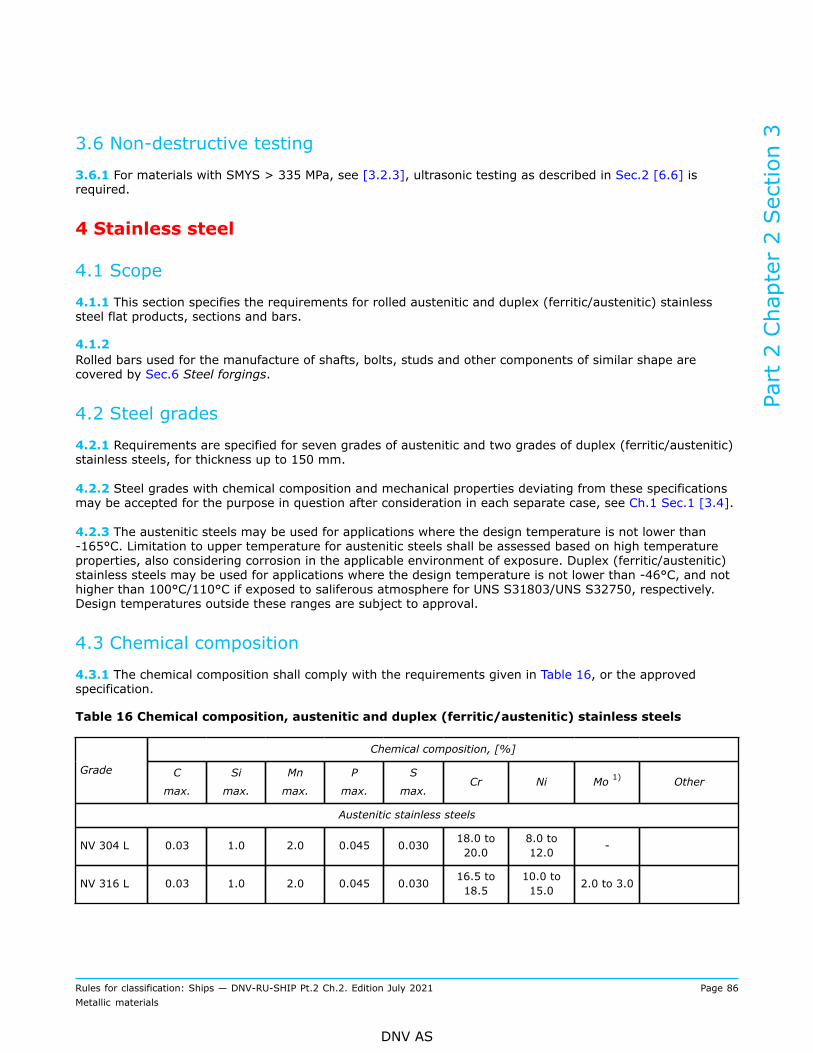
3.6 Non-destructive testing
3.6.1 For materials with SMYS > 335 MPa, see [3.2.3], ultrasonic testing as described in Sec.2 [6.6] isrequired.
4 Stainless steel
4.1 Scope
4.1.1 This section specifies the requirements for rolled austenitic and duplex (ferritic/austenitic) stainlesssteel flat products, sections and bars.
4.1.2 Rolled bars used for the manufacture of shafts, bolts, studs and other components of similar shape arecovered by Sec.6 Steel forgings.
4.2 Steel grades
4.2.1 Requirements are specified for seven grades of austenitic and two grades of duplex (ferritic/austenitic)stainless steels, for thickness up to 150 mm.
4.2.2 Steel grades with chemical composition and mechanical properties deviating from these specificationsmay be accepted for the purpose in question after consideration in each separate case, see Ch.1 Sec.1 [3.4].
4.2.3 The austenitic steels may be used for applications where the design temperature is not lower than-165°C. Limitation to upper temperature for austenitic steels shall be assessed based on high temperatureproperties, also considering corrosion in the applicable environment of exposure. Duplex (ferritic/austenitic)stainless steels may be used for applications where the design temperature is not lower than -46°C, and nothigher than 100°C/110°C if exposed to saliferous atmosphere for UNS S31803/UNS S32750, respectively.Design temperatures outside these ranges are subject to approval.
4.3 Chemical composition
4.3.1 The chemical composition shall comply with the requirements given in Table 16, or the approvedspecification.
Table 16 Chemical composition, austenitic and duplex (ferritic/austenitic) stainless steels
Chemical composition, [%]
Grade C
max.
Si
max.
Mn
max.
P
max.
S
max.Cr Ni Mo 1) Other
Austenitic stainless steels
NV 304 L 0.03 1.0 2.0 0.045 0.030 18.0 to20.0
8.0 to12.0 -
NV 316 L 0.03 1.0 2.0 0.045 0.030 16.5 to18.5
10.0 to15.0 2.0 to 3.0
Part 2 Chapter 2 Section 3
Rules for classification: Ships — DNV-RU-SHIP Pt.2 Ch.2. Edition July 2021 Page 86Metallic materials
DNV AS
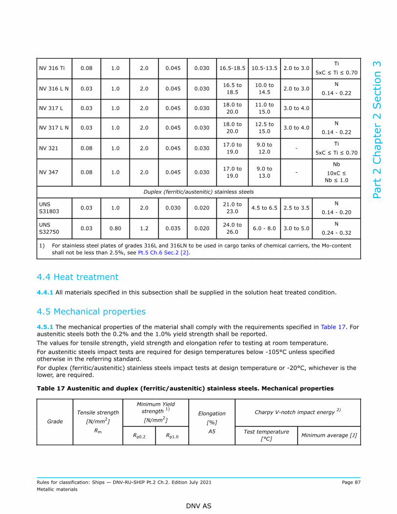
NV 316 Ti 0.08 1.0 2.0 0.045 0.030 16.5-18.5 10.5-13.5 2.0 to 3.0Ti
5xC ≤ Ti ≤ 0.70
NV 316 L N 0.03 1.0 2.0 0.045 0.030 16.5 to18.5
10.0 to14.5 2.0 to 3.0
N
0.14 - 0.22
NV 317 L 0.03 1.0 2.0 0.045 0.030 18.0 to20.0
11.0 to15.0 3.0 to 4.0
NV 317 L N 0.03 1.0 2.0 0.045 0.030 18.0 to20.0
12.5 to15.0 3.0 to 4.0
N
0.14 - 0.22
NV 321 0.08 1.0 2.0 0.045 0.030 17.0 to19.0
9.0 to12.0 -
Ti
5xC ≤ Ti ≤ 0.70
NV 347 0.08 1.0 2.0 0.045 0.030 17.0 to19.0
9.0 to13.0 -
Nb
10xC ≤Nb ≤ 1.0
Duplex (ferritic/austenitic) stainless steels
UNSS31803 0.03 1.0 2.0 0.030 0.020 21.0 to
23.0 4.5 to 6.5 2.5 to 3.5N
0.14 - 0.20
UNSS32750 0.03 0.80 1.2 0.035 0.020 24.0 to
26.0 6.0 - 8.0 3.0 to 5.0N
0.24 - 0.32
1) For stainless steel plates of grades 316L and 316LN to be used in cargo tanks of chemical carriers, the Mo-contentshall not be less than 2.5%, see Pt.5 Ch.6 Sec.2 [2].
4.4 Heat treatment
4.4.1 All materials specified in this subsection shall be supplied in the solution heat treated condition.
4.5 Mechanical properties
4.5.1 The mechanical properties of the material shall comply with the requirements specified in Table 17. Foraustenitic steels both the 0.2% and the 1.0% yield strength shall be reported.The values for tensile strength, yield strength and elongation refer to testing at room temperature.For austenitic steels impact tests are required for design temperatures below -105°C unless specifiedotherwise in the referring standard.For duplex (ferritic/austenitic) stainless steels impact tests at design temperature or -20°C, whichever is thelower, are required.
Table 17 Austenitic and duplex (ferritic/austenitic) stainless steels. Mechanical properties
Minimum Yieldstrength 1)
[N/mm2]Charpy V-notch impact energy 2)
Grade
Tensile strength
[N/mm2]
RmRp0.2 Rp1.0
Elongation
[%]
A5 Test temperature[°C] Minimum average [J]
Part 2 Chapter 2 Section 3
Rules for classification: Ships — DNV-RU-SHIP Pt.2 Ch.2. Edition July 2021 Page 87Metallic materials
DNV AS
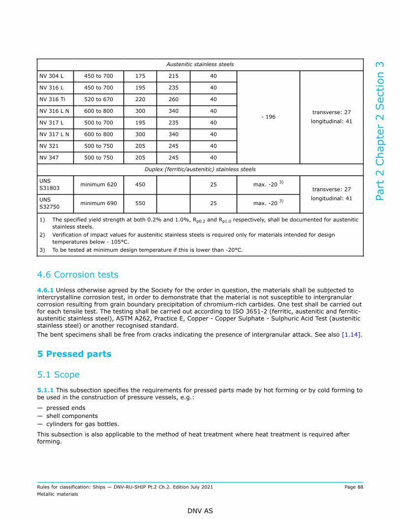
Austenitic stainless steels
NV 304 L 450 to 700 175 215 40
NV 316 L 450 to 700 195 235 40
NV 316 Ti 520 to 670 220 260 40
NV 316 L N 600 to 800 300 340 40
NV 317 L 500 to 700 195 235 40
NV 317 L N 600 to 800 300 340 40
NV 321 500 to 750 205 245 40
NV 347 500 to 750 205 245 40
- 196transverse: 27
longitudinal: 41
Duplex (ferritic/austenitic) stainless steels
UNSS31803 minimum 620 450 25 max. -20 3)
UNSS32750 minimum 690 550 25 max. -20 3)
transverse: 27
longitudinal: 41
1) The specified yield strength at both 0.2% and 1.0%, Rp0.2 and Rp1.0 respectively, shall be documented for austeniticstainless steels.
2) Verification of impact values for austenitic stainless steels is required only for materials intended for designtemperatures below - 105°C.
3) To be tested at minimum design temperature if this is lower than -20°C.
4.6 Corrosion tests
4.6.1 Unless otherwise agreed by the Society for the order in question, the materials shall be subjected tointercrystalline corrosion test, in order to demonstrate that the material is not susceptible to intergranularcorrosion resulting from grain boundary precipitation of chromium-rich carbides. One test shall be carried outfor each tensile test. The testing shall be carried out according to ISO 3651-2 (ferritic, austenitic and ferritic-austenitic stainless steel), ASTM A262, Practice E, Copper - Copper Sulphate - Sulphuric Acid Test (austeniticstainless steel) or another recognised standard.The bent specimens shall be free from cracks indicating the presence of intergranular attack. See also [1.14].
5 Pressed parts
5.1 Scope
5.1.1 This subsection specifies the requirements for pressed parts made by hot forming or by cold forming tobe used in the construction of pressure vessels, e.g.:
— pressed ends— shell components— cylinders for gas bottles.
This subsection is also applicable to the method of heat treatment where heat treatment is required afterforming.
Part 2 Chapter 2 Section 3
Rules for classification: Ships — DNV-RU-SHIP Pt.2 Ch.2. Edition July 2021 Page 88Metallic materials
DNV AS

Provision is made for carbon and carbon-manganese, alloy, and austenitic steels, except for austeniticmanganese alloy steels which shall be specially considered.
5.1.2 Where required by the relevant design and construction parts of the rules, pressed parts shall complywith the requirements of Ch.1, the general requirements in Sec.1 and this subsection.Further requirements for pressed parts are given in the relevant design and construction rules, e.g. Pt.4Ch.7.
5.2 Manufacture
5.2.1 General: all pressed parts delivered with NV or works (W) certificate shall be made at works approvedby the Society for the type, grade and thickness of pressed parts being supplied and for the relevantprocessing route as per [1] to [4] and Sec.4, see also Ch.1 Sec.2 [2.2.2]. The forming and heat treatmentshall be carried out in accordance with the manufacturer’s established procedures describing each operationaland controlling step.
5.2.2 Requirements applicable to the starting plates or pipes:
1) Where the pressed parts shall be delivered with NV or works (W) certificate, the starting materialsapplied for the pressed parts shall also be delivered with NV or works (W) certificate from an approvedmanufacturer.
2) The grades of steel from which the starting plates or pipes are made shall be specified in the order. Inselecting them, care shall be taken to ensure that they fulfil the requirements to be met by the basematerial concerned after forming and, where applicable, heat treatment.
3) The plates or pipes may be supplied in the stipulated final heat-treated condition or in another conditionwhich facilitates the subsequent forming. In the latter case, testing of the starting plates or pipesshall be performed using test specimens which have undergone the heat treatment intended for thefinished part. The condition of supply of the plates or pipes and the method of heat treatment of the testspecimens shall be indicated in the test certificate.
5.2.3 General principles for forming: requirements for calculation of the deformation rate are given in Ch.4Sec.6 [5.2].
5.2.4 Preheating for the hot forming operation: as far as possible, all parts shall be uniformly heated for theforming operation in their entirety.
1) When approved by the Society, local heating may be accepted. In these cases the area heated to theforming temperature shall, however, embrace the whole area of deformation.
2) The temperatures, holding times and heating and cooling rates shall be determined by reference to thedata contained in the standards or manufacturer's specifications, in accordance with the material and thecomponent concerned.
3) Where the testing of finished parts is allowed to be carried out on separate test samples, provisionshall be made to ensure that these receive the same heat treatment as the finished part. The samplingpractice shall be performed in accordance with an agreed procedure.
4) Hot forming of plates or pipes with delivery condition QT or TM requires special consideration andapproval.
5.2.5 Heat treatment after hot forming of ferritic steels:
1) general:hot forming shall normally be followed by renewed heat treatment as prescribed for the base material.However, some exceptions are given as follows:
Part 2 Chapter 2 Section 3
Rules for classification: Ships — DNV-RU-SHIP Pt.2 Ch.2. Edition July 2021 Page 89Metallic materials
DNV AS

2) heat treatment exceptions after hot forming:provided that the full cycle of preheating and hot forming operation has been carried out at atemperature within the normalising temperature range, some exceptions from the required full heattreatment apply as follows:
— for normalised steels, subsequent normalising may be omitted— for normalised, or air quenched and tempered steels, subsequent tempering may be sufficient— in the case of 5% and 9% Ni steels calling for triple normalising heat treatment, two normalisingheat treatments after hot forming may be sufficient. Proved the material was normalised before hotforming, one normalising heat treatment after hot forming may be sufficient
3) the manufacturer's material specification or the applicable standard shall specify the normalisingtemperature range
4) the exceptional provisions set out in [5.2.5] 2) may also be applied where localized heating and hotforming is performed, provided that, prior to forming, the plates or pipes were in a heat-treatedcondition appropriate to the material.
5.2.6 Heat treatment after hot forming of austenitic steels: After hot forming, parts made of austenitic steelsshall be subjected to renewed heat treatment, i.e. typically solution heat treatment and rapid cooling.This may be waived where the hot forming operation begins in the temperature range from 1150°C to1000°C and:
— for stabilized steels and steels with C ≤ 0.03%: forming is ended above 750°C followed by rapid cooling toambient temperature
— for non-stabilized steels with C ≤ 0.08%: forming is ended above 875°C followed by rapid cooling toambient temperature.Guidance note:For hot forming of austenitic steels, guidance may be found in e.g. EN 10088 or AD 2000-Merkblatt HP/7.3.
---e-n-d---o-f---g-u-i-d-a-n-c-e---n-o-t-e---
5.2.7 Heat treatment after hot forming of clad steel plates: For pressed parts made of clad steel plates,the heat treatment is governed by the applied base material. However, where the cladding materialrequires a heat treatment different from that of the base material, the heat treatment shall be done as permanufacturer's specification and as per approved drawing where applicable. The details shall be recorded andreported by the manufacturer.
5.2.8 Heat treatment after cold forming of ferritic steels: The starting material shall be in the prescribedcondition of supply before cold forming is carried out.
1) Cold formed pressure vessel componentsDue to the possible changes in material properties caused by cold forming and ageing, the material shallbe heat treated after cold forming. However, heat treatment may be waived for the applications andconditions given in Table 18. For acceptance of waived heat treatment, the material manufacturer shallbe approved by the Society for the steel grade in question.
Table 18 Conditions where heat treatment after cold forming may be waived
Intended application Steel type/gradeDeformation degree forwhich heat treatmentmay be waived
Pressure vessels operated at ambient temperatures orfeedstock temperatures down to minus (-) 10°C
All ≤ 5%
Part 2 Chapter 2 Section 3
Rules for classification: Ships — DNV-RU-SHIP Pt.2 Ch.2. Edition July 2021 Page 90Metallic materials
DNV AS

Intended application Steel type/gradeDeformation degree forwhich heat treatmentmay be waived
NV 3.5Ni
NV 5Ni
NV 9Ni
NV Mn 4001)
≤ 5%Pressure vessels operated at charging mediatemperatures below minus (–) 10°C, as well as gas tankswith design temperatures below 0°C
C and C-Mn,
Alloy (other than above)
≤ 3%
1) NV Mn400 is actually an austenitic steel, however with regard to application is treated in the same manner asNV 5Ni.
Where the deformation degree above is exceeded and the product will be subject to subsequent welding,a suitable heat treatment shall be performed before welding is carried out.If the acceptable degree of cold deformation is exceeded, renewed heat treatment of the final product isrequired in order to restore the delivery condition specified for the material in question.Subject to case by case approval and for special cases, stress relieving heat treatment may be acceptedin lieu of full heat treatment. For such cases, the impact toughness shall be qualified for the maximumapplicable strained material after stress relieving heat treatment.
2) Cold formed endsCold-formed ends, including those fabricated from welded round blanks, shall be heat treated(normalised or quenched and tempered) in accordance with the relevant standards or materialspecifications.
3) Cold formed dished endsFor cold-formed dished ends made of steel grades with nominal yield strengths not exceeding 275 MPa,heat treatment is not required if all of the following conditions are fulfilled:
— the temperature of the charging media is –10°C or above— the design temperature TD ≤ 120°C and— the nominal wall thickness t ≤ 8 mm.
4) Heat treatment after cold forming of materials with delivery condition QT or TMFor cold forming exceeding the limits given in Table 18, heat treatment of QT and TM steels requiresspecial consideration and acceptance by the Society.
5.2.9 Heat treatment after cold forming of austenitic steels alloyed with CrNi: Solution heat treatment orstabilization annealing followed by quenching is required, depending on the austenitic steel grade.
Guidance note:For heat treatment of austenitic steels, guidance may be found in e.g. EN 10088 or AD 2000 Merkblatt (AD Data Sheet) HP/7.3.
---e-n-d---o-f---g-u-i-d-a-n-c-e---n-o-t-e---
Heat treatment after cold forming of solution heat treated or stabilization annealed material may bedispensed with for:
a) steels with specified minimum elongation A5 ≥ 30% for the starting materialb) materials where the specified minimum elongation A5 < 30%, and proof is furnished that:
— the degree of cold deformation is ≤ 15% and the starting material certificate shows elongation A5 ≥30%, or
— the residual elongation A5 ≥ 15% after cold forming
c) for cold deformation > 15%, proof is furnished that the residual elongation A5 ≥ 15% after cold forming
Part 2 Chapter 2 Section 3
Rules for classification: Ships — DNV-RU-SHIP Pt.2 Ch.2. Edition July 2021 Page 91Metallic materials
DNV AS

d) in the case of dished, ellipsoidal and hemispherical ends, the following elongations are achieved for thestarting material:
— A5 ≥ 40% for nominal wall thicknesses t ≤ 15 mm at design temperatures TD ≥ –196°C— A5 ≥ 45% for nominal wall thicknesses t > 15 mm at design temperatures TD ≥ –196°C— A5 ≥ 50% for design temperatures TD < –196°C.
5.2.10 Heat treatment after cold forming of austenitic steels alloyed with Mn is not required for deformationequal to or less than 5%.
5.2.11 Heat treatment after cold forming of clad plates: For pressed parts made of clad steel plates, theheat treatment is governed by the applied base material. Where the cladding material requires a heattreatment different from that of the base material, the heat treatment shall be done as per manufacturer'sspecification and as per approved drawing where applicable. The details shall be recorded and reported bythe manufacturer.
5.3 Mechanical properties
5.3.1 Scope of testing is given in Table 19.The testing of pressed parts shall comprise tensile and notched bar impact tests performed on specimenstaken from the finished parts after the final forming and heat treatment. Test specimens orientation shallbe transverse to the original rolling direction of the plate or pipe. A deviation up to 20° from the requiredspecimen orientation is accepted. Test specimen orientation for small diameter pipes or small bendingradiuses may be specially considered.
5.3.2 For hot formed pressed parts, the test samples shall be taken from surplus material at the edges of thepressed parts or from cut-outs.For cold formed pressed parts, the following requirements apply:
— test samples shall be taken either from the finished parts in the area with the maximum plasticdeformation, or
— from surplus material at the edges of the finished parts, which are subsequently subjected to the relevantmaximum plastic deformation in the cold condition.
Where stress relief heat treatment would suffice after forming, the test samples may be removed from theproduct before heat treatment but shall be subjected to the same deformation rate and heat treatment.Where batch testing is applicable for pressed parts, a test batch may only comprise items made from platesor pipes originating from the same cast which have been deformed and heat treated in the same way. Thewall thicknesses of items within a test batch may vary by 20% from the mean wall thickness. The number ofsets of specimens shall be determined as follows:
— up to 10 items: 1 set of specimens— up to 25 items: 2 sets of specimens— over 25 items: 3 sets of specimens.
Where the material is tested after final forming and heat treatment, the requirements for mechanical testingof the starting material will be dispensed with as specified in Table 19. It is a precondition that the materialmanufacturer is approved by the Society.
5.3.3 Alternative sampling for cold formed parts: for cold formed products not subject to subsequent heattreatment, but complying with the requirements/exceptions of [5.2.8] to [5.2.11], the following alternative totesting of finished pressed parts may be agreed with the Society:
— testing of the starting plate or pipe with one set of test specimens per piece, see definition in Sec.1 Table1.
For this alternative, there are two pre-conditions:
Part 2 Chapter 2 Section 3
Rules for classification: Ships — DNV-RU-SHIP Pt.2 Ch.2. Edition July 2021 Page 92Metallic materials
DNV AS
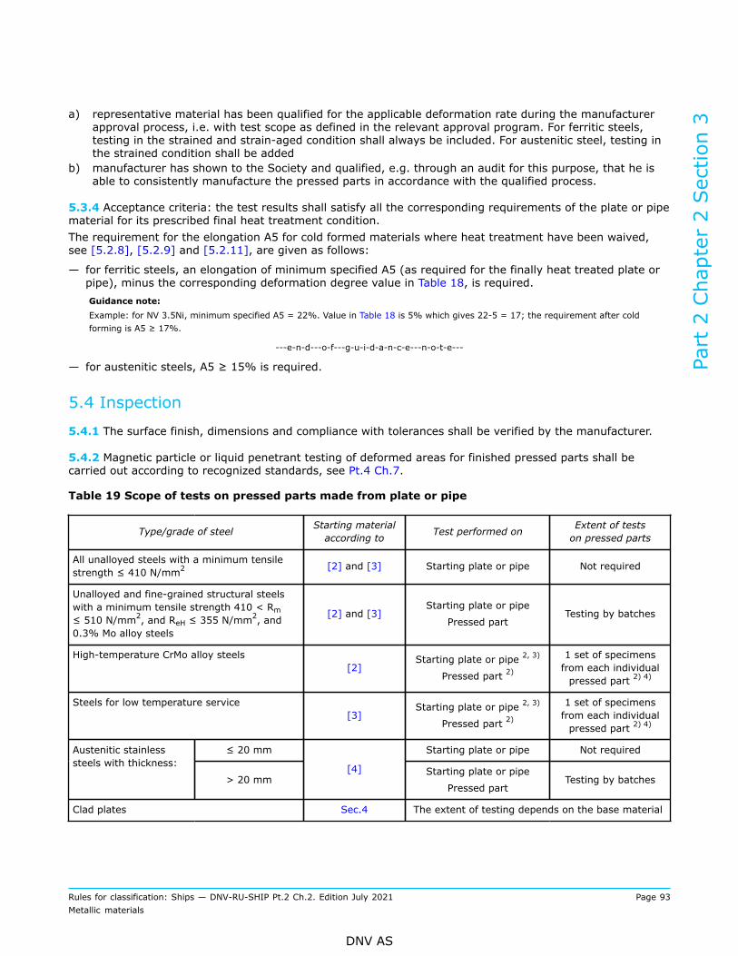
a) representative material has been qualified for the applicable deformation rate during the manufacturerapproval process, i.e. with test scope as defined in the relevant approval program. For ferritic steels,testing in the strained and strain-aged condition shall always be included. For austenitic steel, testing inthe strained condition shall be added
b) manufacturer has shown to the Society and qualified, e.g. through an audit for this purpose, that he isable to consistently manufacture the pressed parts in accordance with the qualified process.
5.3.4 Acceptance criteria: the test results shall satisfy all the corresponding requirements of the plate or pipematerial for its prescribed final heat treatment condition.The requirement for the elongation A5 for cold formed materials where heat treatment have been waived,see [5.2.8], [5.2.9] and [5.2.11], are given as follows:
— for ferritic steels, an elongation of minimum specified A5 (as required for the finally heat treated plate orpipe), minus the corresponding deformation degree value in Table 18, is required.Guidance note:Example: for NV 3.5Ni, minimum specified A5 = 22%. Value in Table 18 is 5% which gives 22-5 = 17; the requirement after coldforming is A5 ≥ 17%.
---e-n-d---o-f---g-u-i-d-a-n-c-e---n-o-t-e---
— for austenitic steels, A5 ≥ 15% is required.
5.4 Inspection
5.4.1 The surface finish, dimensions and compliance with tolerances shall be verified by the manufacturer.
5.4.2 Magnetic particle or liquid penetrant testing of deformed areas for finished pressed parts shall becarried out according to recognized standards, see Pt.4 Ch.7.
Table 19 Scope of tests on pressed parts made from plate or pipe
Type/grade of steel Starting materialaccording to Test performed on Extent of tests
on pressed parts
All unalloyed steels with a minimum tensilestrength ≤ 410 N/mm2 [2] and [3] Starting plate or pipe Not required
Unalloyed and fine-grained structural steelswith a minimum tensile strength 410 < Rm≤ 510 N/mm2, and ReH ≤ 355 N/mm
2, and0.3% Mo alloy steels
[2] and [3]Starting plate or pipe
Pressed partTesting by batches
High-temperature CrMo alloy steels[2]
Starting plate or pipe 2, 3)
Pressed part 2)1 set of specimensfrom each individualpressed part 2) 4)
Steels for low temperature service[3]
Starting plate or pipe 2, 3)
Pressed part 2)1 set of specimensfrom each individualpressed part 2) 4)
≤ 20 mm Starting plate or pipe Not requiredAustenitic stainlesssteels with thickness:
> 20 mm[4] Starting plate or pipe
Pressed partTesting by batches
Clad plates Sec.4 The extent of testing depends on the base material
Part 2 Chapter 2 Section 3
Rules for classification: Ships — DNV-RU-SHIP Pt.2 Ch.2. Edition July 2021 Page 93Metallic materials
DNV AS

Type/grade of steel Starting materialaccording to Test performed on Extent of tests
on pressed parts
1) For pressed parts which are designed for the manufacture of tanks carrying pressure-liquefied ammonia, seerespective design rules.
2) Testing of starting plate or pipe may be agreed with the Society under the condition that the test material have beensubjected to deformation and heat treatment corresponding to that of the final product.
3) For testing of pressed parts, mechanical testing of starting plate or pipe may be dispensed with, see [5.3.2].4) Batch testing may be accepted with the following limitations:
— plates/pipes from the same piece, see Sec.1 Table 1 for definition— of same products size, shape, thickness— subject to the same forming operations— heat treated in the same furnace charge— see also [5.3.2] for maximum batch size.
Part 2 Chapter 2 Section 3
Rules for classification: Ships — DNV-RU-SHIP Pt.2 Ch.2. Edition July 2021 Page 94Metallic materials
DNV AS

SECTION 4 CLAD PRODUCTS
1 General requirements
1.1 Scope
1.1.1 This section specifies the requirements for clad steel plates consisting of a base material and a thinnerlayer of cladding metal on one or both sides, continuously and integrally bonded. The clad metals covered arestainless steels, aluminium and copper-nickel alloys.Furthermore, explosion bonded steel-aluminium joints for the connection of steel structure with aluminiumstructure are covered.
1.1.2 Where required by the relevant design and construction parts of the rules, clad products shall complywith the requirements of Sec.1, the general requirements of [1] and the appropriate specific requirements of[2] and [3]. If the specific requirements differ from the general requirements, the specific requirements shallprevail.
1.2 Required compliance documentation
1.2.1 General compliance document requirements are given in Sec.1 [3.1]. Additional certificationrequirements for materials covered by this section are given in Table 1 and [1.2.2].
Table 1 Additional certification requirements
Object Additional descriptionCompliancedocumenttype
Validated by Compliancestandard
Base materials and cladmaterials
Starting material for clad products NV or W DNV forNV andmanufacturerfor W
*)
*) Unless otherwise specified the compliance standard is the DNV rules.
1.2.2 The manufacturer shall provide the type of compliance document required in the relevant constructionrules giving the following particulars for each test unit which has been accepted:
a) purchaser’s name, order number and, if known, the vessel identificationb) manufacturer’s namec) description of products and steel gradesd) identification marking of productse) for the starting materials (base material, clad metal), NV or works (W) certificate with the particulars as
stipulated in Sec.2 and Sec.3f) condition of supplyg) results of mechanical testsh) results of ultrasonic testsi) results of any supplementary and additional test requirements specified.
Part 2 Chapter 2 Section 4
Rules for classification: Ships — DNV-RU-SHIP Pt.2 Ch.2. Edition July 2021 Page 95Metallic materials
DNV AS

1.3 Documentation requirements
1.3.1 General documentation requirements are given in Sec.1 [3.2]. Additional manufacturer specificdocumentation requirements are given in Table 2.
Table 2 Qualification documentation for manufacturer
Item Documentation type Additional description
Z100 - Specification the thickness of the cladding metal is subject toapproval by the Society in each case
Clad products
Z266 - Measurement report — the thickness of the cladding materials measuredat the edges and in the middle of the plate
— the records shall be presented to the surveyor onrequest.
1.4 Survey, inspection and testing requirements
1.4.1 General survey, inspection and testing requirements are given in Ch.1 Sec.1 [3.3]. Additional specificrequirements are given in Table 3, as further detailed in this section.
Table 3 Additional survey and testing requirements
Survey, inspection and testing item Description
Chemical composition required for all materials
Tensile test and impact toughness test required for all grades covered by this chapter unless otherwisespecified
Bend test requires for all clad products, and when specified for steel-aluminium transition joints
Shear test required for all steel-aluminium transition joints, and whenspecified for clad steel products
Through thickness tensile test at least three specimens shall be prepared from each end of thesteel-aluminium transition joint (plate, rod or circular blank)
Testing of bond quality by UT — unless otherwise specified in each subsection, UT shall beperformed to check the bonding quality
— if bonding defects are found, their extent shall be clearlymarked and reported to the surveyor
Intergranular corrosion test in the case of austenitic and austenitic-ferritic cladding materialsIf it is required to determine the resistance of the cladding metalagainst intergranular corrosion for each test batch
Repair by welding before welding, the dimensions and location of the defects shallbe reported to the surveyor for acceptance of the repair.
Part 2 Chapter 2 Section 4
Rules for classification: Ships — DNV-RU-SHIP Pt.2 Ch.2. Edition July 2021 Page 96Metallic materials
DNV AS
1.5 Manufacture
1.5.1 All clad products delivered with NV or works (W) certificate shall be made at works approved by theSociety for the type, grade and thickness of clad product being supplied and for the relevant processing routeas per Sec.2 and Sec.3, respectively, see also Ch.1 Sec.2 [2.2.2].
1.5.2 Base material and cladding materials applied for the clad products shall be delivered with NV or works(W) certificate from an approved manufacturer.
1.5.3 If the plates are intended for participation in the vessel's strength, the base material is at least tosatisfy the requirements for the corresponding hull material as per Sec.2. If the plates are intended forboilers or pressure vessels, the base material shall at least satisfy the requirements for materials for suchcomponents as per Sec.3.
1.5.4 The cladding metal may be metallurgically bonded to the base metal by any method that will produce aclad material which will conform to the requirements of this section.
1.6 Chemical composition
1.6.1 Base metals suitable for joining with the clad metal will be accepted, provided that the process has noadverse effects on the finished plates.
1.7 Condition of supply
1.7.1 The clad products shall be supplied in that condition of heat treatment which is most appropriate forboth types of material. The material shall not be subjected to any kind of heat treatment by the user, beyondwhat is recommended by the manufacturer and approved by the Society.
1.8 Mechanical testing
1.8.1 For plate thickness equal to or less than 50 mm, and unless otherwise agreed, tensile and bend testspecimens shall be of the flat type and the test specimens shall have the full thickness of the plate. Wherethe thickness of the plate is more than 50 mm, or if necessary for the capacity of the testing machine, thethickness of the test specimen may be reduced by machining.On single clad plates, both sides of the test specimen shall be machined to maintain the same ratio ofcladding materials to base steel materials as in the product, but the cladding materials need not be reducedto less than 3 mm.Test specimens of double clad plates may be reduced by dividing according to a recognized standard. In thiscase, both halves shall be tested.
1.8.2 If the results do not meet the specified requirements, the test unit is rejected, or the re-testprocedures in Ch.1 Sec.2 [3.8] may be adopted.
1.9 Inspections, dimensions and tolerances
1.9.1 The surface finish and dimensions of all products shall be checked by the manufacturer. Surfaceinspection and verification of dimensions are the responsibility of the manufacturer. Acceptance by thesurveyor of material later found to be defective shall not absolve the manufacturer from this responsibility.
Part 2 Chapter 2 Section 4
Rules for classification: Ships — DNV-RU-SHIP Pt.2 Ch.2. Edition July 2021 Page 97Metallic materials
DNV AS

1.9.2 Each clad product shall be inspected by the manufacturer before delivery.The clad products shall be free from injurious defects and shall have a workmanlike appearance.The surface finish of the base material shall comply with the respective requirements specified in Sec.2[2.11], Sec.3 [1.15] and Sec.3 [1.16].The clad materials shall have a smooth surface consistent with their purpose. The surface shall be free fromscale, impurities, annealing colour and other defects which may impair the manufacturing processes, theapplication of the product, or its chemical stability.
1.9.3 The base materials shall satisfy the requirements for minus tolerances on thickness according to Sec.2[2.11] and Sec.3 [1.15]. The thickness control shall be carried out by the manufacturer.
1.9.4 The thickness of the cladding metal is subject to approval by the Society in each case.The thickness of the cladding materials shall be measured at the edges and in the middle of the platecomplying with the requirements of [2] and [3]. The results shall be recorded. The records shall be presentedto the surveyor on request.
1.9.5 Bond quality: The cladding metal shall be integrally and continuously bonded to the base metal. Unlessotherwise specified in each subsection, UT shall be performed to check the bonding quality in accordancewith the general practice of recognized standards, e.g. ASTM A578. If bonding defects are found, their extentshall be clearly marked and reported to the surveyor.For different clad products, acceptance criteria of bond quality by UT are given in [2.5.1] and [3.5.1],respectively.
1.10 Repair
1.10.1 Repair of defects shall comply with the requirements of [2.6] and [3.5.1].
1.11 Identification
1.11.1 In addition to marking as required in Ch.1 Sec.2 [4] the following shall be marked on the product:
— material grade for both base and cladding material— thickness of base and cladding material.
On single clad plates, the marking shall be stamped on the surface of the base plate. On double clad plates,all marking shall be done with a colour seal rather than by stamping.
2 Clad steel plates
2.1 Scope
2.1.1 These requirements are supplementary to [1] and apply to clad steel plates with cladding materialsmade of stainless steels and intended for the manufacture of e.g. containers and tanks, for chemical tankers,etc.
Guidance note:It may be agreed to apply these rules to plate clad with other materials, e. g. aluminium or copper-nickel alloys.
---e-n-d---o-f---g-u-i-d-a-n-c-e---n-o-t-e---
Part 2 Chapter 2 Section 4
Rules for classification: Ships — DNV-RU-SHIP Pt.2 Ch.2. Edition July 2021 Page 98Metallic materials
DNV AS

2.2 Manufacture
2.2.1 Cladding may be performed by rolling or explosive cladding or by a combination of the two methods.
2.3 Chemical composition
2.3.1 Cladding materials of austenitic stainless steel shall be delivered with carbon content limitations strictlyfollowing Sec.3 Table 16. Other stainless steels, nickel and nickel-base alloys will be accepted, when they aresuited for the intended service.
2.4 Mechanical and corrosion testing
2.4.1 Tensile test: For steels for construction of hull structure, one set of tensile tests shall be taken fromevery fifth plate, and at least one set from each cast and each thickness interval. For steel for construction ofpressure vessels, one set of tensile tests shall be taken from each plate. The tensile tests shall be performedon transverse specimens. The gauge marks shall be applied to the base material side. One set of tensile testsconsists of one or two tests:
1) one test of the base metal after removal of the cladding metal. The test shall satisfy the requirements forthe base material
2) provided the cladding will be considered for the strength calculation; One test from the full clad platewhich shall have a tensile strength Rm not less than derived from the following formula:
(1)
R m1 = minimum tensile strength of base metalR m2 = minimum tensile strength of the cladding metalS = nominal thickness of the clad plate = S1 + S2S1 = nominal thickness of the base metalS2 = nominal thickness of the cladding metal.
2.4.2 Elongation: In the case of clad steels where the elongation of the cladding material is less than that ofthe base material, the cladding material shall attain an elongation A5 of at least 12% in a tensile test afterthe base metal has been removed by machining.
2.4.3 Impact test: Where impact test is required for the respective materials, see Sec.2 and Sec.3, it shallcomply with the requirements specified for the base material in each case.
2.4.4 Bend test: As an alternative or in addition to the shear test provided in [2.4.5], bend test shall becarried out with the following conditions:
a) two bend test specimens shall be taken from each plateb) on single clad plates, one test specimen shall be bent with the cladding in tension and the other with the
cladding in compression. On double clad plates, the test specimens shall be bent, so that both claddingmetals are tested both ways
c) the diameter of the mandrel shall be twice the plate thickness when the tensile strength of the plate isless than 490 N/mm2, and three times the thickness of the plate when the tensile strength is more than490 N/mm2
d) the bend test specimens shall be bent 180° around a mandrel without showing signs of cracking orloosening of the cladding metal from the base material.
Part 2 Chapter 2 Section 4
Rules for classification: Ships — DNV-RU-SHIP Pt.2 Ch.2. Edition July 2021 Page 99Metallic materials
DNV AS

2.4.5 Shear test: The shear strength between the base and the cladding metal shall be determined inorder to ensure proper bonding. A shear test is required to decide the shear strength between the baseand the cladding metal. One shear test shall be made from each plate in accordance with ASTM A264 orother recognized standards. In the case of clad materials with a tensile strength of less than 280 N/mm2,the shear strength shall be at least 50% of the minimum tensile strength of the clad material. For all otherclad materials it shall not be less than 140 N/mm2, irrespective of the direction of testing, unless otherwiseagreed in the order.
2.4.6 Corrosion test: In the case of austenitic cladding materials the resistance of the cladding metal againstintergranular corrosion shall be determined. For this purpose, the plates may be grouped together in testbatches which have been clad in the same manufacturing cycle with cladding materials originating from thesame cast. Testing shall be carried out according to ASTM A262, Practice E (Copper — Copper Sulphate —Sulphuric Acid Test), or to another recognised standard. Extent of testing is each batch.
Guidance note:By adding approximately 50 gram electrolytic copper to 1000 millilitres solution, the boiling time can be reduced to 15 hours. Thebase material shall be removed before the testing.
---e-n-d---o-f---g-u-i-d-a-n-c-e---n-o-t-e---
2.5 Inspection
2.5.1 Ultrasonic test: To check the bonding, ultrasonic testing shall be made. If bonding defects are found,their extent shall be clearly marked and reported to the surveyor. Rules for repairs are given in [2.6]. Thearea adjacent to the edges of each plate shall be checked 100% for a width of at least 50 mm. Further testsshall be made at points equally distributed on the surface with maximum intervals of 150 mm.
2.5.2 Bond quality: Unless more stringent requirements have been specified, the proportion of bondedsurface shall be at least 95%, and the area of isolated points where bonding has not occurred shall notexceed 50 cm2.
Guidance note:The bond quality to be supplied should preferably be listed on the purchase order.For clad steels which are severely stressed during processing, e.g. in the manufacture of dished ends, or while in use, e.g. in tube-sheets, it may be necessary for the purchaser to impose more stringent requirements.
---e-n-d---o-f---g-u-i-d-a-n-c-e---n-o-t-e---
2.5.3 Dimensions and tolerances: The nominal thickness of the cladding material shall be at least 2 mm,unless otherwise approved.Where no closer thickness tolerances are specified in the order, the minus tolerances for the thickness shallbe as shown in Table 4.
Table 4 Minus tolerances in relation to the thickness of the cladding material
Nominal thickness, t [mm] Minus tolerance [mm]
2.0 ≤ t < 2.5
2.5 ≤ t < 3.0
3.0 ≤ t < 3.5
3.5 ≤ t < 4.0
t ≥ 4.0
-0.20
-0.25
-0.35
-0.45
-0.50
Part 2 Chapter 2 Section 4
Rules for classification: Ships — DNV-RU-SHIP Pt.2 Ch.2. Edition July 2021 Page 100Metallic materials
DNV AS

2.6 Repair
2.6.1 Shallow defects in the cladding material, e.g. impressions, grooves and scratches, shall be removed bygrinding within the tolerance specified in [2.5.3].
2.6.2 Minor surface defects and bonding defects which do not exceed the limits specified in [2.6.3], may berepaired by means of welding. Bonding defects along the edges shall be repaired.
2.6.3 The plate will be rejected if:
— a repair will cause a weakening of the plate— a bonding defect exceeds 400 cm2 for plates up to 15 mm in thickness and 800 cm2 for plates over 15mm, or several bonding defects amounting in total to more than 5% of the surface of the plate revealed.
2.6.4 Before welding, the dimensions and location of the defects shall be reported to the surveyor foracceptance of the repair. Repair by welding shall be subject to the following requirements:
— all welds shall be made by qualified welders using an approved welding processes and weldingconsumables
— the welds shall be free from any defects liable to impair the characteristics of the cladding— after welding, the repaired defect shall be ground flush with the plate. Welding shall be followed by heattreatment if this is specified by the welding procedure qualification tests or if called for in the order
— after final machining, the plates shall be subjected to a suitable non-destructive test technique, e.g. PT, inorder to prove that the repairs are free from defects
— for each repair weld the manufacturer shall record the dimensions and location of the defects, the detailsof the welding technique used, the nature of any heat treatment applied and the results of the test. Onrequest, the report shall be submitted to the surveyor.
3 Steel-aluminium transition joints
3.1 Scope
3.1.1 These requirements are supplementary to [1] and apply to explosion-bonded steel-aluminium jointsintended for the connection of steel structures with aluminium structures. Steel-aluminium tranition jointsare typically of a tri-clad type with a soft intermediate layer of e.g. alloy 1050.
3.2 Manufacture
3.2.1 The product is formed by explosive cladding without additional heat transfer or change of thickness.
3.2.2 The clad products shall be delivered in smoothed condition, unless otherwise agreed.
3.3 Chemical composition
3.3.1 Steels produced according to Sec.2 or Sec.3 shall be used as base materials.
3.3.2 Wrought aluminium alloys produced according to Sec.10 shall be used as cladding material. It is notrequired that the intermediate layer of tri-clad steel-aluminium joints follow the requirements of Pt.2 Ch.2Sec.10.
Part 2 Chapter 2 Section 4
Rules for classification: Ships — DNV-RU-SHIP Pt.2 Ch.2. Edition July 2021 Page 101Metallic materials
DNV AS

3.4 Mechanical testing3.4.1 Extent of testing for through thickness tensile test and shear testExtent of testing for through thickness testing and shear testing is given as follows:
— samples shall be extracted from both ends of the product— for each end, the following shall be carried out:
— testing of the 'as manufactured' condition, testing shall be carried out at 25°C ± 5°C— testing after heating to a temperature of 300°C for 15 minutes, testing shall be carried out at 25°C ±5°C.
3.4.2 Through thickness tensile testingThrough thickness tensile test is required for product thickness ≥ 15 mm.The specimens shall be tested with their longitudinal axis perpendicular to the product surface (across thecladding).Specimen shape shall be chosen according to Sec.2 [6.4].The tensile strength of a clad product shall be at least 60 N/mm2, unless higher values have been agreed inthe order.As an alternative to the through thickness test, ram tensile test as per MIL-J-24445A may be performed. Insuch case, the ram tensile strength shall be at least 75 N/mm2.
3.4.3 Shear testingThe shear strength between the base and the cladding metal shall be determined in order to ensure properbonding.Shear test specimens shall be made with its axis transverse to the rolling direction and tested in accordancewith DIN 50162 or other recognized standards. The dimensions of the test specimen and the testarrangement are shown in Figure 1.
Figure 1 Shear test
The shear strength shall be at least 60 N/mm2 irrespective of the direction of testing, unless higher valueshave been agreed in the order.
Part 2 Chapter 2 Section 4
Rules for classification: Ships — DNV-RU-SHIP Pt.2 Ch.2. Edition July 2021 Page 102Metallic materials
DNV AS

3.4.4 Side bend testingSide bend test shall be carried out if specially agreed in the order, one specimen of each clad product shall betaken and tested. Dimensions of the test specimen and test arrangement are shown in Figure 2.
Figure 2 Side bend test
The mandrel shall have a diameter equal to six times the thickness of the specimen. Where the productthickness exceeds 80 mm, the specimens may be reduced to 80 mm by machining the base material side.When tested, the clad product shall be capable of being bent through 90° without separation of the claddingmaterial or formation of incipient cracks.
3.5 Inspection
3.5.1 Bonding quality: The manufacturer shall carry out 100% ultrasonic testing of the surfaces and edges ofall products.The proportion of bonded surface shall be at least 99%. For rods and bars with width or diameter up to 300mm, the size of individual indications shall not exceed the evaluation level given for UT of rolled steel plates,see DNV-CG-0051. For other products and sizes, the area of isolated points where bonding has not occurredshall not exceed 6.5 cm2. If products are cut in order to remove indications, the distance to registeredindications shall be at least 20 mm.
3.5.2 Dimensions and tolerances: Where no other tolerances are specified in the order, the details in Table 5apply.
Part 2 Chapter 2 Section 4
Rules for classification: Ships — DNV-RU-SHIP Pt.2 Ch.2. Edition July 2021 Page 103Metallic materials
DNV AS

Table 5 Permissible tolerances of steel-aluminium transition joints
Tolerance [mm]Dimension Product
Lower Upper
Thickness All -2 +1
Length All 0 +10
Plates 0 +10
< 25 mm width -1.5 +1.5
Width
Rods 1)≥ 25 mm width -2 +2
< 500 mm width 0 +2DiameterCircular blanks
≥ 500 mm width 0 +5
Rectangularity Plates
(difference between the diagonals)Max. 10
< 1 m length Max. 0.5% of lengthEvenness (aluminium side)
≥ 1 m length Max. 5
Straightness of longitudinal edges Rods 1) Max. 5
1) contrary to plates, rods are flat products of width < 300 mm.
Part 2 Chapter 2 Section 4
Rules for classification: Ships — DNV-RU-SHIP Pt.2 Ch.2. Edition July 2021 Page 104Metallic materials
DNV AS

SECTION 5 STEEL PIPES AND FITTINGS
1 General requirements for pipes
1.1 Scope
1.1.1 This subsection specifies the general requirements for steel pipes to be used in the construction ofpiping for pressure, cargo, and process systems. Provision is made for carbon and carbon-manganese, alloy,and stainless steels.
1.1.2 Separate requirements for steel pipe fittings are given in [6]. Requirements for pipes and fittings offorgings and castings are given in Sec.6 and Sec.8 respectively.
1.1.3 Requirements for pipes and hollow sections intended for structural application are given in Sec.2.
1.1.4 Requirements for individually manufactured and welded pipes for applications not covered by thissection shall comply with the relevant design and construction rules.
1.2 Required compliance documentation
1.2.1 General compliance document requirements are given in Sec.1 [3.1].
1.2.2 The product shall be delivered with the type of compliance document required in the relevant designand construction rules giving at least the following particulars for each test unit which has been accepted:
— purchaser's name, order number and vessel identification, where known— manufacturer’s name— description of pipes/fittings and material quality— identification marking of pipes/fittings— cast number and chemical composition— results of mechanical tests and technological tests— results of leak tightness testing— results of any supplementary and additional test requirements specified.
1.3 Documentation requirements
1.3.1 General documentation requirements are given in Sec.1 [3.2]. Additional manufacturer specificdocumentation requirements are given in Table 1.
Table 1 Qualification documentation for manufacturer
Item Documentation type Additional description
Carbon and carbon-manganese steel pipes
NV or W certificate or TR — unless otherwise required by the standard,suitable grain refining elements may be used atthe discretion of the manufacturer. The content ofsuch elements shall be reported
— carbon equivalent shall be reported.
Part 2 Chapter 2 Section 5
Rules for classification: Ships — DNV-RU-SHIP Pt.2 Ch.2. Edition July 2021 Page 105Metallic materials
DNV AS

1.4 Survey, inspection and testing requirements
1.4.1 General survey, inspection and testing requirements are given in Ch.1 Sec.1 [3.3]. Additional specificrequirements are given in Table 2, as further detailed in this section.
Table 2 Additional survey and testing requirements
Survey, inspection and testing item Description
Chemical composition required for all materials
Carbon equivalent unless stricter requirements are specified in the standard, carbonand carbon-manganese steel shall conform to a carbon equivalentof maximum 0.50%
Mechanical testing required for all grades in accordance with the requirements of therelevant standard
Hot tensile test where pipes are designed for use at elevated temperatures onthe basis of their high-temperature strength characteristics, a hottensile test shall be performed on one test specimen per cast andper pipe size
Impact toughness test, all pipes except as specified for materials whichshall comply with the rulesPt.5 Ch.7 (for low temperature service), impact testing is notrequired for material thickness less than 6 mm. For materials thatshall comply with the rules Pt.5 Ch.7, see Ch.1 Sec.3 [3.3.6].
Impact toughness test of austenitic steel pipes for austenitic stainless steel pipes, Charpy V-notch impact testingis required where the design temperature is below -105°C
Hardness test on fittings hardness tests on fittings shall be carried out as specified in [6]
NDT of all pipes where required by the design principle, pipes shall be subjectedto a non-destructive test over their whole length
NDT of welded pipes for welded pipes, an automatic non-destructive testing of thewhole length of the weld is required
Leak tightness test each pipe shall be subjected to a hydraulic test or an approvednon-destructive test for leak tightness in accordance with therequirements of the relevant standard
Test equipment used for the continuous inspection ofpipes
the efficiency of the equipment shall be demonstrated to thesurveyor on request
Corrosion test of pipes and fittings where pipes/fittings of austenitic stainless steels shall be used insystems where corrosion testing of the pipes is required, testingshall be carried out in accordance with Sec.3 [1.14]
Corrosion test for duplex (ferritic/austenitic) stainlesssteels
for duplex (ferritic/austenitic) stainless steel pipes, corrosiontesting in accordance with ASTM G48 Method A or an equivalentstandard is required
Repair by grinding — defects may be removed by grinding provided that thedimensional tolerances are not exceeded
— repair by welding is not permitted except for repair to theweld seam of electric fusion welded pipe
Part 2 Chapter 2 Section 5
Rules for classification: Ships — DNV-RU-SHIP Pt.2 Ch.2. Edition July 2021 Page 106Metallic materials
DNV AS

NDT and Leak tightness test after repair — defects removed by grinding shall be re-inspected by NDT— for pipes/fittings repaired by welding, both leak tightness test
according to [1.10] and inspection according to [1.11] shall berepeated after repair.
1.5 Materials
1.5.1 Pipes shall be in accordance with recognised standards, as given in [2] to [5], provided thatsupplementary requirements contained herein and in [2] to [5] also are met. Recognition of other standardsis subject to submission to the Society for evaluation, see Ch.1 Sec.1 [3.4].
1.5.2 Pipe grades selected from recognised standards shall be suitable for bending, flanging, and similarforming operations, and for welding.
1.5.3 Where required by the relevant design and construction parts of the rules, pipes shall comply with therequirements of Ch.1 and this section.
1.5.4 Where the use of material with differing requirements is proposed, particulars shall be submitted inconnection with the approval of the design for which the material is proposed. As a minimum the followingparticulars shall be specified:
— manufacturing process— chemical composition— heat treatment— mechanical properties— leak tightness testing— non-destructive testing.
Guidance note:In order for other materials to be considered for approval, a gap analysis report identifying the differences between the proposedmaterial and a corresponding material grade according to one of the standards listed below should be submitted, see Ch.1 Sec.1[3.4].
---e-n-d---o-f---g-u-i-d-a-n-c-e---n-o-t-e---
1.5.5 For carbon-manganese steel and other materials with definitive yield points, consideration shall begiven to the limitation of the yield to tensile ratio.
1.6 Manufacture
1.6.1 All pipes delivered with NV or works certificate shall be made by works approved by the Society, seeCh.1 Sec.2 [2.2.2]. The steel used shall be made by works approved by the Society.
1.6.2 Pipes shall be manufactured as specified in [2] to [5]. The terms 'hot finished' and 'cold finished' applyto the condition of the pipe before it is heat-treated.
1.7 Chemical composition
1.7.1 The chemical composition of each cast shall be determined by the steel manufacturer on a sampletaken preferably during the pouring of the cast and shall be in accordance with the requirements of therelevant standard. When multiple casts are tapped into a common ladle, the ladle analysis shall apply.
Part 2 Chapter 2 Section 5
Rules for classification: Ships — DNV-RU-SHIP Pt.2 Ch.2. Edition July 2021 Page 107Metallic materials
DNV AS

1.7.2 Unless otherwise required by the standard, suitable grain refining elements may be used at thediscretion of the manufacturer. The content of such elements shall be reported.
1.7.3 Elements designated as residual elements in the standard shall not be intentionally added to the steel.The content of such elements shall be reported.
1.7.4 Unless stricter requirements are specified in the standard, carbon and carbon-manganese steel shallconform to a carbon equivalent Ceq of maximum 0.50% as determined by the formula given in Ch.1 Sec.2[3.3].
1.8 Condition of supply
1.8.1 The pipes shall be supplied in a condition in accordance with the requirements of the relevant standardand the requirements in [2] to [5]. Unless otherwise required, hot finished or as-welded pipes need not beheat-treated.
1.9 Mechanical testing
1.9.1 Pipes shall be sampled and subjected to testing in accordance with the requirements of the relevantstandard.
1.9.2 Unless stricter requirements are specified in the standard, the size of a test unit (batch) shall berestricted to maximum:
— 400 pipes for outside diameter < 100 mm— 100 pipes for outside diameter ≤ 500 mm— 50 pipes for outside diameter > 500 mm.
Further details are given in [1.9.3] and [1.9.4].
1.9.3 Where heat treatment has been carried out, a test unit shall consist of pipes of the same size, samegrade of steel, same heat treatment in a continuous furnace or heat-treated in the same furnace charge in abatch furnace, and in case of alloy steel pipes, from the same cast.
1.9.4 Where no heat treatment has been carried out, a test unit shall consist of pipes of the same size, madeby the same method, and from the same grade of steel.
1.9.5 Where pipes are designed for use at elevated temperatures on the basis of their high-temperaturestrength characteristics, a hot tensile test shall be performed on one test specimen per cast and per pipesize. The test is not required if the pipes are made according to a recognized standard where the high-temperature mechanical properties are regarded as proven.
1.9.6 Except as specified for materials that shall comply with the rules Pt.5 Ch.7 (for low temperatureservice), impact testing is not required for pipes with nominal wall thickness less than 6 mm. For materialswhich shall comply with the rules Pt.5 Ch.7, impact testing is not required for materials with thickness lessthan 3 mm, see Ch.1 Sec.3 [3.3.6].Unless otherwise specified by the selected recognised standard for the grade in question, transverse CharpyV-notch specimens shall be used for outside diameter of D ≥ 200 mm. For outside diameter D < 200 mm,longitudinal specimens may be used. The notch shall be placed in through thickness position.If the dimensions of the pipe are such that transverse test specimens can be taken without straightening, anadditional (transverse) set of specimens shall be taken from fusion-welded pipes so that the notch is locatedin the centre of the weld metal.
Part 2 Chapter 2 Section 5
Rules for classification: Ships — DNV-RU-SHIP Pt.2 Ch.2. Edition July 2021 Page 108Metallic materials
DNV AS

1.10 Leak tightness testing
1.10.1 Each pipe shall be subjected to a hydraulic test or an approved non-destructive test for leak tightnessin accordance with the requirements of the relevant standard. Unless stricter requirements are specified inthe standard, the testing shall be as given in [1.10.2].
1.10.2 The internal pressure test shall be performed at a standard hydraulic test pressure of 70 bars or at atest pressure calculated using the following equation, whichever is lower:
P = applicable test pressure [bar]D = nominal outside diameter [mm]t = nominal wall thickness [mm]σr = stress [MPa], calculated to 70% of the specified minimum yield strength.The test pressure shall be held for not less than 5 sec. for tubes with nominal outside diameter D less thanor equal to 457 mm and for not less than 10 sec. for tubes with nominal outside diameter D greater than 457mm.Where pipes are intended for an operating pressure of ≤ 25 bars, the test pressure may be reduced to astandard value of 50 bars. Where, in exceptional cases, testing with water is not possible, another testingmedium may be used in agreement with the surveyor.
1.11 Inspection
1.11.1 Pipes shall be subjected to visual inspection and measurements of dimensions by the manufacturer inaccordance with the requirements of the relevant standard. Unless stricter requirements are specified in thestandard, the pipes shall be inspected at the same frequency as that required for mechanical testing.
1.11.2 All products shall satisfy the surface finish requirements of the applied pipe standard. Unlessotherwise specified in the referred standard, the following apply:
— products shall have a finish appropriate to the manufacturing route— products shall be free from laps, laminations, seams, visible cracks, tears, slivers, pits and otherdetrimental imperfections
— minor surface discontinuities which may occur under normal manufacturing conditions and within thethickness tolerances of the products are accepted.
1.11.3 For welded pipes, an automatic non-destructive testing of the whole length of the weld is required.Such pipes are considered equivalent to seamless pipes for design purpose.
1.11.4 Where required by the design principle, pipes shall be subjected to a non-destructive test over theirwhole length in accordance with a recognized standard, e.g. EN ISO 10893.
1.11.5 The test equipment used for the continuous inspection of pipes shall be regularly calibrated usingpipes with artificial defects. The efficiency of the equipment shall be demonstrated to the surveyor onrequest.
1.12 Repair
1.12.1 Defects may be removed by grinding provided that the dimensional tolerances are not exceeded.Repair by welding is not permitted except for repair to the weld seam of electric fusion welded pipe. Defects
Part 2 Chapter 2 Section 5
Rules for classification: Ships — DNV-RU-SHIP Pt.2 Ch.2. Edition July 2021 Page 109Metallic materials
DNV AS
removed by grinding shall be re-inspected by NDT. For pipes/fittings repaired by welding, both leak tightnesstest according to [1.10] and inspection according to [1.11] shall be repeated after repair.
1.13 Identification
1.13.1 Pipes shall be legibly marked for identification in accordance with the requirements of the relevantstandard with the following minimum information:
— manufacturer's name or trade mark— material designation— where applicable, quality level in the case of boiler tubes— cast number or production code.
2 Pipes for pressure systems
2.1 Scope
2.1.1 These requirements are supplementary to [1] and apply to carbon and carbon-manganese and alloysteel pipes for use in pressure systems.
2.2 Materials
2.2.1 Suitable pipe grades shall be selected from the following recognised standards:
— ISO 9329 Parts 1 and 2, ISO 9330 Parts 1 and 2— EN 10216 Parts 1 to 3, EN 10217 Parts 1 to 3, EN 10305 Part 1 and 2 (limited to delivery condition N -normalised)
— ASTM A53, ASTM A106, ASTM A135, ASTM A335— JIS G3454, JIS G3455, JIS G3456, JIS G3458.
In addition, those standards given in [4] and [5] may be used.
2.3 Manufacture
2.3.1 Pipes for class I and II pressure systems, as defined in Pt.4 Ch.7, shall be manufactured by any of thefollowing methods:
— hot finished seamless— cold finished seamless— electric resistance or induction welded— cold finished electric resistance or induction welded— electric fusion welded.
2.4 Mechanical testing2.4.1 Pipes for class I and II pressure vessels shall satisfy a Charpy V-notch impact toughness requirement ofminimum 27 J, unless otherwise approved by the Society, or the applied standard specifies higher values.
Part 2 Chapter 2 Section 5
Rules for classification: Ships — DNV-RU-SHIP Pt.2 Ch.2. Edition July 2021 Page 110Metallic materials
DNV AS

3 Austenitic and ferritic-austenitic steel pipes
3.1 Scope
3.1.1 These requirements are supplementary to [1] and apply to austenitic stainless and ferritic-austeniticstainless steel pipes for corrosive service and to austenitic steel pipes for low-temperature service.
3.2 Materials
3.2.1 Suitable pipe grades shall be selected from the following recognised standards:
— ISO 9329 Part 4, ISO 9330 Part 6— EN 10216 Part 5, EN 10217 Part 7— ASTM A269, ASTM A312, ASTM A358, ASTM A789, ASTM A790, ASTM A928— JIS G3459.
3.3 Manufacture
3.3.1 Pipes shall be manufactured by any of the following methods:
— hot finished seamless— cold finished seamless— electric resistance or induction welded— cold finished electric resistance or induction welded— electric fusion welded.
3.4 Condition of supply
3.4.1 The austenitic and duplex (ferritic/austenitic) stainless steel pipes shall be supplied in solution heattreated condition.Welded austenitic pipes may be delivered in the as-welded state provided all of the following is compliedwith:
— the steel has specified carbon content of maximum 0.03%, or maximum 0.08% for titanium and niobiumstabilized grades
— the manufacturer has demonstrated through qualification testing (e.g. through the manufacturer approvalprocess) that the characteristics of the as-welded pipes are satisfactory
— the strips or plates used for their manufacture are solution heat treated.
3.5 Mechanical testing
3.5.1 Where pipes are used at elevated temperatures, the required values for the 0.2% or 1% proofstress prescribed in the relevant standards or recognized specifications shall be met at the correspondingtemperature level.
3.5.2 For austenitic stainless steel pipes, Charpy V-notch impact testing is required where the designtemperature is below -105°C. Testing shall be carried out at -196°C and the average energy value forstandard 10 mm wide test specimens shall be minimum 41 J.
Part 2 Chapter 2 Section 5
Rules for classification: Ships — DNV-RU-SHIP Pt.2 Ch.2. Edition July 2021 Page 111Metallic materials
DNV AS

3.6 Corrosion testing
3.6.1 For duplex (ferritic/austenitic) stainless steel pipes, corrosion testing in accordance with ASTM G48method A or an equivalent standard is required.
3.6.2 Test specimen surfaces shall have a finish representative of the pipe’s delivery condition. The testspecimens shall be exposed to the solution at a constant temperature of +22°C (±2°C) for type 22Cr duplexand +50°C (±2°C) for type 25Cr duplex for 24 hours. No pitting on specimen surfaces is allowed whenviewed at 20 times magnification. The specimen mass loss shall be less than 4.0 g/m2.
4 Pipes for low-temperature service
4.1 Scope
4.1.1 These requirements are supplementary to [1] and apply to carbon and carbon-manganese and alloysteel pipes for use in piping systems for liquefied gases where the design temperature is less than 0°C. Theserequirements are also applicable for other types of pressure piping systems where the use of steels withguaranteed impact properties at low temperatures is required. For pipes with thickness t > 25 mm case bycase approval is required.
4.2 Materials
4.2.1 Suitable pipe grades shall be selected from the following recognised standards:
— ISO 9329 Part 3, ISO 9330 Part 3— EN 10216 Part 4, EN 10217 Part 6— ASTM A333, ASTM A334— JIS G3460.
4.3 Manufacture
4.3.1 Carbon and carbon-manganese steel pipes shall be manufactured by any of the following methods:
— hot finished seamless— cold finished seamless followed by heat treatment— electric resistance or induction welded— cold finished electric resistance or induction welded followed by heat treatment— electric fusion welded.
4.3.2 Nickel alloy steel pipes shall be manufactured by a seamless process.
4.4 Mechanical testing
4.4.1 Requirements for Charpy V-notch impact testing dependent of steel type and minimum designtemperature are given in Table 3.
Part 2 Chapter 2 Section 5
Rules for classification: Ships — DNV-RU-SHIP Pt.2 Ch.2. Edition July 2021 Page 112Metallic materials
DNV AS
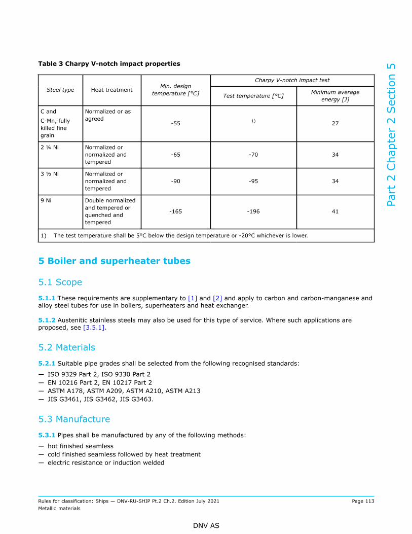
Table 3 Charpy V-notch impact properties
Charpy V-notch impact test
Steel type Heat treatment Min. designtemperature [°C] Test temperature [°C] Minimum average
energy [J]
C and
C-Mn, fullykilled finegrain
Normalized or asagreed
-55 1) 27
2 ¼ Ni Normalized ornormalized andtempered
-65 -70 34
3 ½ Ni Normalized ornormalized andtempered
-90 -95 34
9 Ni Double normalizedand tempered orquenched andtempered
-165 -196 41
1) The test temperature shall be 5°C below the design temperature or -20°C whichever is lower.
5 Boiler and superheater tubes
5.1 Scope
5.1.1 These requirements are supplementary to [1] and [2] and apply to carbon and carbon-manganese andalloy steel tubes for use in boilers, superheaters and heat exchanger.
5.1.2 Austenitic stainless steels may also be used for this type of service. Where such applications areproposed, see [3.5.1].
5.2 Materials
5.2.1 Suitable pipe grades shall be selected from the following recognised standards:
— ISO 9329 Part 2, ISO 9330 Part 2— EN 10216 Part 2, EN 10217 Part 2— ASTM A178, ASTM A209, ASTM A210, ASTM A213— JIS G3461, JIS G3462, JIS G3463.
5.3 Manufacture
5.3.1 Pipes shall be manufactured by any of the following methods:
— hot finished seamless— cold finished seamless followed by heat treatment— electric resistance or induction welded
Part 2 Chapter 2 Section 5
Rules for classification: Ships — DNV-RU-SHIP Pt.2 Ch.2. Edition July 2021 Page 113Metallic materials
DNV AS

— cold finished electric resistance or induction welded followed by heat treatment.
6 Piping fittings
6.1 Scope
6.1.1 This subsection specifies the requirements for steel piping fittings such as elbows, bends, tees,reducers and caps - for the applications covered in [2] to [5], made from plates, seamless pipes or weldedpipes. Detachable pipe couplings and flanges are excluded from these requirements.Steel pipe fittings made by forging or casting are covered by Sec.6 and Sec.8, respectively.
6.2 Materials
6.2.1 Fittings shall be in accordance with recognised standards, as given in [6.2.2]. Recognition of otherstandards is subject to submission to the Society for evaluation, see Ch.1 Sec.1 [3.4].
6.2.2 Suitable fitting grades shall be selected from the following recognised standards:
— EN 10253— ASTM A234, ASTM A403, ASTM A420, ASTM A774, ASTM A815, ASTM A960, ASTM A961— JIS B2312, JIS B2313, JIS B2316.
6.2.3 Where required by the relevant design and construction parts of the rules, fittings shall comply withthe requirements of [1] and this subsection.
6.2.4 Where the use of material with differing requirements is proposed, particulars shall be submitted inconnection with the approval of the design for which the material is proposed. As a minimum the followingparticulars shall be specified:
— manufacturing process— chemical composition— heat treatment— mechanical properties.
6.3 Manufacture
6.3.1 All fittings delivered with NV or works (W) certificate shall be made by works approved by the Society.See also Ch.1 Sec.2 [2.2.2] and guidance note.
Guidance note:Exceptions may be accepted in a transition period as decided by the Society, in which fittings for NV or W certification may beaccepted from non-approved manufacturers. Such manufacturers should apply for approval. Manufacturers in which approvalcertificate is suspended or withdrawn are not covered by this exception.
---e-n-d---o-f---g-u-i-d-a-n-c-e---n-o-t-e---
6.3.2 The starting materials for fabrication of fittings (covered by this section) shall consist of plates,seamless pipes or welded pipes and shall be sourced from works approved by the Society for fittings to bedelivered with NV or works (W) certificate.
6.3.3 Fittings shall be manufactured by forming operations such as pressing, bending or fusion weldingaccording to recognized standards.
Part 2 Chapter 2 Section 5
Rules for classification: Ships — DNV-RU-SHIP Pt.2 Ch.2. Edition July 2021 Page 114Metallic materials
DNV AS

6.4 Chemical composition
6.4.1 Chemical composition of the starting materials shall fulfil [1.7].
6.5 Condition of supply
6.5.1 All fittings shall be in the heat-treated or hot worked state specified for the material in the relevantstandard or material specification.
6.5.2 Heat treatment after cold bending shall be carried out as specified in Pt.4 Ch.6 Sec.10 [3].
6.6 Mechanical testing
6.6.1 Fittings shall be tested in accordance with the requirements of the relevant standard. For stainlesssteel fittings and fittings for low-temperature service, the supplementary requirements for testing given in[3] and [4] also apply.
6.6.2 Unless stricter requirements are specified in the standard, the size of a test unit shall be restricted tothe maximum size given in Table 4 and as given in [6.6.3] and [6.6.4].
Table 4 Test units for fittings
Size da [mm] 1) No. of fittings per test unit 2)
< 100 ≤ 200
100 ≤ da < 225 ≤ 100
225 ≤ da < 350 ≤ 50
da ≥ 350 ≤ 25
1) da = outer diameter.2) For elbows: the test unit size applies to 90° elbows. The number of elbows in each test unit is halved in the case of
180° elbows and doubled in the case of 45° elbows.
6.6.3 Where heat treatment has been carried out, a test unit shall consist of fittings of the same size, madefrom the same grade of steel, the same heat treatment in a continuous furnace or heat-treated in the samefurnace charge in a batch furnace, and in the case of alloy steel fittings with an outer diameter da > 100 mm,originating from the same cast.
6.6.4 Where no heat treatment has been carried out, a test unit shall consist of fittings of the same size,made by the same forming process, and from the same grade of steel.Where the fittings are delivered without heat treatment, and have been subject to theoretical cold formingof less than 5% for ferritic steels and less than 10% for austenitic and ferritic-austenitic steels, testing ofthe starting material is sufficient. Theoretical cold forming may be calculated in accordance with Ch.4 Sec.6[5.2.6]. See also the requirements given in Pt.4 Ch.6 Sec.10 [3].
6.6.5 Testing shall be carried out on selected fitting from the unit to be covered. Provided the length of thefitting is not sufficient for testing, fittings of excess length shall be manufactured using the same or a similarprocess, and shall follow the test unit as described in [6.6.3] and [6.6.4].The test samples shall be prepared from the hardest and softest fittings determined in the hardness test, see[6.6.6].
Part 2 Chapter 2 Section 5
Rules for classification: Ships — DNV-RU-SHIP Pt.2 Ch.2. Edition July 2021 Page 115Metallic materials
DNV AS
6.6.6 Hardness tests shall be carried out on 10% of the fittings per test unit, except for austenitic andaustenitic-ferritic steels subject to tensile testing on the fitting. Where the number of fittings per test unit isless than 30 fittings a minimum of three fittings shall be tested.Hardness test shall be performed on each individual fitting for the following:
— outer diameter D ≥ 225 mm for unalloyed steel with tensile strength Rm ≥ 500 MPa— outer diameter D ≥ 200 mm for alloyed steel, except for 0.3% Mo and Cr-Mo steel, which shall follow therequirement for unalloyed steel.
6.6.7 One tensile test shall be carried out for each test unit unless stricter requirements are specified in theapplied standard. Sample product shall be selected as the softest fitting found in hardness tests according to[6.6.6]. Fittings having an outer diameter D < 100 mm may be tensile tested on the starting material.
6.6.8 Except as specified for materials that shall comply with the rules Pt.5 Ch.7 (for low temperatureservice), impact testing is not required for material thickness less than 6 mm. For materials that shall complywith the rules Pt.5 Ch.7, see Ch.1 Sec.3 [3.3.6].Where the fittings are delivered without heat treatment and have been subject to theoretical cold formingof more than 5% for ferritic steels and more than 10% for austenitic and ferritic-austenitic steels, the areawith the highest cold forming shall be tested. Where sampling of the representative area is not possible,testing of same material in artificially cold formed condition is accepted. For ferritic steels, the material shalladditionally be tested in the strain-aged condition, see Ch.1 Sec.3 [3.9], Ch.4 Sec.6 [5.2] and Pt.4 Ch.6Sec.10 [3].
6.7 Corrosion testing
6.7.1 Where fittings of austenitic stainless steels shall be used in systems where corrosion testing of thepipes is required, appropriate corrosion testing shall be carried out in accordance with agreed standard, e.g.ASTM A262 Practice E, Copper - Copper Sulphate - Sulphuric Acid Test for intercrystalline corrosion testing,ASTM G48 for pitting or crevice corrosion testing, or to another recognised standard.
6.7.2 For duplex (ferritic/austenitic) stainless steel pipes fittings, corrosion testing in accordance with ASTMG48 Method A or an equivalent standard is required.
6.7.3 Test specimen surfaces shall have a finish representative of the fitting's delivery condition. The testtemperature shall be +22°C ±2 for type 22Cr duplex and +50°C ±2 for type 25Cr duplex for 24 hours. Nopitting on specimen surfaces is allowed when viewed at 20 times magnification. The specimen mass loss shallbe less than 4.0 g/m2.
6.8 Inspection
6.8.1 Fittings shall be subject to visual inspection and measurements of dimensions by the manufacturer.Surface quality and dimensions shall be in accordance with the requirements of the relevant standard.The fittings shall have a workmanlike finish consistent with the method of manufacture and shall be free fromexternal and internal defects that can be detected by visual inspection.
6.8.2 Unless stricter requirements are specified in the standard, welded alloy steel fittings with nominalbores > 75 mm shall be subject to random radiographic inspection of the welds. These shall be selected insuch a way that every size of fittings is included.
Part 2 Chapter 2 Section 5
Rules for classification: Ships — DNV-RU-SHIP Pt.2 Ch.2. Edition July 2021 Page 116Metallic materials
DNV AS

6.9 Identification
6.9.1 Fitting with outer diameter D ≥ 225 mm shall be marked in accordance with [1.13]. Smaller fittingsmay alternatively be marked with the manufacturer´s symbol and a unique identification number ensuringtraceability to the test unit and certificate.The level of documentation shall be in accordance with [1.3].
Part 2 Chapter 2 Section 5
Rules for classification: Ships — DNV-RU-SHIP Pt.2 Ch.2. Edition July 2021 Page 117Metallic materials
DNV AS
SECTION 6 STEEL FORGINGS
1 General requirements
1.1 Scope
1.1.1 This section specifies the general requirements for:
— steel forgings to be used in the construction of hulls, equipment, machinery, boilers, pressure vessels andpiping systems, and forgings for low temperature service
— semi-finished rolled or forged products for forging stock and to forgings from which blanks for variouscomponents may be cut out
— rolled bars intended for machining into components of simple shape, e.g. shafts, bolts, studs and othercomponents
— bolts and nuts.
1.1.2 Where required by the relevant design and construction parts of the rules, steel forgings shall complywith the requirements of Ch.1, the general requirements of Sec.1 and [1] and the appropriate specificrequirements of [2] to [9]. If the specific requirements differ from these general requirements, the specificrequirements shall prevail.
1.1.3 As an alternative to [1.1.2], materials which comply with national or proprietary specifications maybe accepted provided such specifications give reasonable equivalence to the requirements of [1] or areespecially approved. As a minimum the following particulars shall be specified:
— manufacturing process— chemical composition— heat treatment— mechanical properties and— non-destructive testing.
For machinery components, see also Pt.4 Ch.1 Sec.1.Guidance note:In order for other materials to be considered for approval, a gap analysis report, identifying the differences between the proposedmaterial and the corresponding the Society material grade should be submitted, see Ch.1 Sec.1 [3.4].
---e-n-d---o-f---g-u-i-d-a-n-c-e---n-o-t-e---
1.1.4 This section contains requirements applicable to general certification of materials. However, forcomponents that shall be certified according to other parts of the rules, the requirements in these partsprevail.
1.2 Required compliance documentation
1.2.1 The general compliance document requirements are given in Sec.1 [3.1].
1.2.2 The manufacturer shall provide the type of compliance document required in the relevant constructionrules giving the following particulars for each test unit which has been accepted:
a) purchaser's name, order number and vessel identification, where knownb) manufacturer’s namec) description of forgings and steel qualityd) identification marking of forgings
Part 2 Chapter 2 Section 6
Rules for classification: Ships — DNV-RU-SHIP Pt.2 Ch.2. Edition July 2021 Page 118Metallic materials
DNV AS
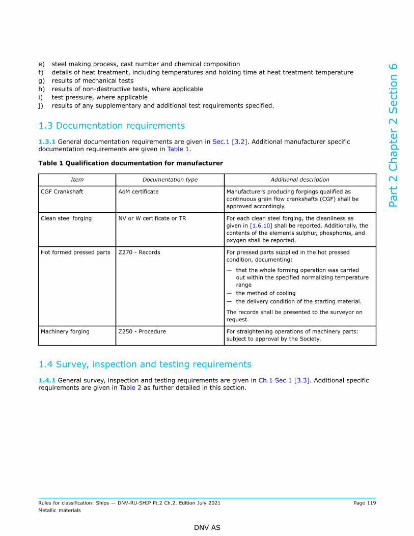
e) steel making process, cast number and chemical compositionf) details of heat treatment, including temperatures and holding time at heat treatment temperatureg) results of mechanical testsh) results of non-destructive tests, where applicablei) test pressure, where applicablej) results of any supplementary and additional test requirements specified.
1.3 Documentation requirements
1.3.1 General documentation requirements are given in Sec.1 [3.2]. Additional manufacturer specificdocumentation requirements are given in Table 1.
Table 1 Qualification documentation for manufacturer
Item Documentation type Additional description
CGF Crankshaft AoM certificate Manufacturers producing forgings qualified ascontinuous grain flow crankshafts (CGF) shall beapproved accordingly.
Clean steel forging NV or W certificate or TR For each clean steel forging, the cleanliness asgiven in [1.6.10] shall be reported. Additionally, thecontents of the elements sulphur, phosphorus, andoxygen shall be reported.
Hot formed pressed parts Z270 - Records For pressed parts supplied in the hot pressedcondition, documenting:
— that the whole forming operation was carriedout within the specified normalizing temperaturerange
— the method of cooling— the delivery condition of the starting material.
The records shall be presented to the surveyor onrequest.
Machinery forging Z250 - Procedure For straightening operations of machinery parts:subject to approval by the Society.
1.4 Survey, inspection and testing requirements
1.4.1 General survey, inspection and testing requirements are given in Ch.1 Sec.1 [3.3]. Additional specificrequirements are given in Table 2 as further detailed in this section.
Part 2 Chapter 2 Section 6
Rules for classification: Ships — DNV-RU-SHIP Pt.2 Ch.2. Edition July 2021 Page 119Metallic materials
DNV AS

Table 2 Additional survey, inspection and testing requirements
Survey, inspection and testing item Description
Chemical composition — required for all materials— unless otherwise required by the standard, suitable grain
refining elements may be used at the discretion of themanufacturer. The content of such elements shall be reported.
Clean steel forgings For clean steel forgings, the steels shall have a degree ofcleanliness as given in [1.6.10]. Additionally, the contents of theelements sulphur, phosphorus, and oxygen shall be restricted tomaximum 0.005%, 0.015%, and 25 ppm, respectively.
Mechanical testing Required for all grades in accordance with the requirements of therelevant section.
Impact toughness test Relevant for all grades where specified in the following sections.
Impact toughness test of austenitic steel forgings Charpy V-notch impact testing is required where the designtemperature is below –105°C.
Hardness test of crankshaft forgings For forgings which have been batch tested, at least 10% of theforgings to be tested for hardness.
Hardness test of forgings for gears, forgings forboilers, pressure vessels and piping systems,and forgings for low-temperature service (exceptaustenitic stainless steels)
For forgings which have been batch tested, each forging to betested.
Visual survey Forgings for which certification by the Society is required shall bepresented to the surveyor for visual survey. The surveyor mayrequire areas to be etched for the purpose of investigating weldrepairs.
NDT Forgings shall be subject to non-destructive testing as specifiedin [2] to [9] and shall comply with given requirements. Inaddition, the relevant construction rules shall be referred for non-destructive testing of finished machined components.
NDT after repair by grinding or chipping Complete elimination of the defective material shall be verified bymagnetic particle testing or liquid penetrant testing.
Pressure test Pressure retaining forgings shall be tested after machining to thetest pressure required by the relevant design and constructionparts of the rules.
1.5 Grading system
1.5.1 The forgings concerned are classified by chemical composition into three steel types:
— carbon and carbon-manganese (C and C-Mn) steel— alloy steel— stainless steel.
1.5.2 Where applicable, C and C-Mn steels and alloy steels are covered by several grades designated bytheir specified minimum tensile strength. Stainless steel shall be designated in accordance with a recognizedstandard.
Part 2 Chapter 2 Section 6
Rules for classification: Ships — DNV-RU-SHIP Pt.2 Ch.2. Edition July 2021 Page 120Metallic materials
DNV AS

Guidance note:For the purpose of this grading system, C and C-Mn steels are classified as one type and considered to be those steels in whichcarbon and manganese are the principal alloying elements.
---e-n-d---o-f---g-u-i-d-a-n-c-e---n-o-t-e---
1.6 Manufacture
1.6.1 All products delivered with NV or works certificate shall be made at works approved by the Society,see Ch.1 Sec.2 [2.2.2]. Manufacturers without own steel making shall use starting material supplied byworks approved by the Society. Special approval is required for the manufacture of clean steel forgings formachinery components, e.g. crankshafts and gearing, where higher stresses are allowed for design purposes.See also [1.6.10].
1.6.2 The steel used in the manufacture of forgings shall be made by a process approved by the Society. Allforgings shall be made from killed steel.
1.6.3 For forgings with specified minimum ultimate tensile strength 800 N/mm2 or above, the molten steelshall be vacuum treated prior to or during pouring of the ingot in order to remove objectionable gases,particularly hydrogen and oxygen, and improve steel cleanliness. Other processes may be accepted providedadequate cleanliness is documented.
1.6.4 Ingots for forgings shall be cast in chill moulds with the larger cross-section up, and with efficientfeeder heads. Adequate top and bottom discards shall be made to ensure freedom from piping and harmfulsegregation in the finished forgings.
1.6.5 Surface and skin defects, which may be detrimental during the subsequent working and formingoperations, shall be removed.
1.6.6 The material shall be progressively hot worked by hammer or press, and shall be forged as close aspractical to the finished shape and size in order to give reasonable machining allowance, see also [1.6.8].Shaping of forgings by flame cutting, scarfing or arc-air gouging shall be undertaken in accordancewith recognised good practice and, unless otherwise approved, shall be carried out before the final heattreatment. Preheating shall to be employed when necessitated by the composition or thickness of the steel.Subsequent grinding or machining is required for certain components.Excessive machining to give the forging its final shape may impair its characteristics e.g. by exposing thecore zone. The core zone may have lower mechanical properties, as well as higher density of inclusions andother imperfections. The manufacturer is responsible for evaluation of the machining allowance suitable fortheir products. As a general advice, machining allowance should not exceed 20% of final dimension.Necks of shafts, pinions and journals exceeding 1/10 of the outer diameter should be produced as far aspossible by stepped forging.The degree of deformation should be such that the core zone of the forging undergoes sufficient plasticdeformation.Surface hardening and surface carburizing caused by flame-scarfing or air-arc gouging will typically beremoved if it is followed by grinding or machining to a depth of 1 mm or more.
1.6.7 The reduction ratio shall be calculated with reference to the average cross-sectional area of the castmaterial. Where an ingot is initially upset, this reference area may be taken as the average cross-sectionalarea after this operation. However, the initial free upsetting operation of the ingot shall not be considered aspart of the total forging reduction ratio.Unless otherwise approved, the total reduction ratio, resp. the ratio for upsetting, shall be at least as statedin Table 3.
Part 2 Chapter 2 Section 6
Rules for classification: Ships — DNV-RU-SHIP Pt.2 Ch.2. Edition July 2021 Page 121Metallic materials
DNV AS

Table 3 Forging ratio and ratio for upsetting
Total forging ratio (cross-section 1,2,3,4)Starting material
Where L > D Where L ≤ D
Ingots, continuous cast products (cut slabs, blooms, billets) min. 3:1 min. 1.5:1
Rolled products min. 4:1 min. 2:1
Rolled bars min. 6:1, see [1.1.1]
In case of no initial forging, orinitial forging less than 1.5:1 L/L1 ≥ 3
In the case of an initial forgingreduction of at least 1.5:1 andup to 3:1
L/L1 ≥ 1.5
In the case of an initial forgingreduction of at least 3:1 L/L1 ≥ 1
Any of the above, orforging; for furtherforging by upsetting5,6,7)
For alternating forging andupsetting
One of the above requirements shall be met at least oncefor the given starting material
1) Forging ratio for forgings not made by upsetting is calculated as cross-section area before forging divided by cross-section area after forging, or length before forging divided by length after forging, whichever is bigger.
2) Forging steps may be added to reach the total forging ratio requirement of 3:1, e.g. initial forging at steel mill plusforging at forge. The requirement is that the cross-section of the final forging shall be ≤ 1/3 of the cross-section ofthe listed starting materials.
3) L is the length and D is the diameter before the given forging operation.4) For complex shapes or special forging operations, other ratios may be agreed subject to special consideration by the
Society.5) Bars with a rolling reduction ratio of at least 6:1 are excluded from this requirement.6) L1 is height after upsetting.7) For forging by upsetting (for head, flange, bolts, coupling etc.), unsupported length (L2) should be: L2 ≤ 3×D.
1.6.8 For crankshafts, where grain flow is specified in the most favourable direction with regard to the modeof stressing in service, the proposed method of manufacture requires special approval by the Society. Insuch cases, tests will be required to demonstrate that satisfactory mechanical properties and grain flow areobtained.
Guidance note:Continuous grain flow (CGF) forged means documented forging that results in a flow of segregations tangential to the mainprincipal stress direction in the web fillets. Further details for qualification of CGF are given in the relevant approval ofmanufacturer program. A crankthrow is among other required to be cut in the crank plane and etched in order to illustrate thegrain flow. It is essential that this is made with fillets in finished condition. I.e. for recessed fillets, CGF may be difficult to obtain asthe recess normally cuts the grain flow.
---e-n-d---o-f---g-u-i-d-a-n-c-e---n-o-t-e---
1.6.9 Where two or more forgings are joined by welding to form a composite item, the welding procedurespecification shall be approved.
1.6.10 Clean steel forgings are forgings with specified cleanliness. This requirement is applicable if thereferring rules require clean steel forgings, e.g. see Pt.4 Ch.4 Sec.2. For clean steel forgings, the steels shallhave a degree of cleanliness as given in Table 4 when tested according to ISO 4967 method A. Samplesshall be obtained from forged or rolled product representative of each cast. Additionally, the contents of the
Part 2 Chapter 2 Section 6
Rules for classification: Ships — DNV-RU-SHIP Pt.2 Ch.2. Edition July 2021 Page 122Metallic materials
DNV AS
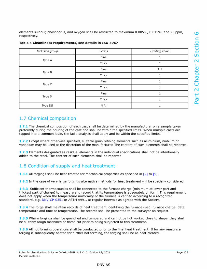
elements sulphur, phosphorus, and oxygen shall be restricted to maximum 0.005%, 0.015%, and 25 ppm,respectively.
Table 4 Cleanliness requirements, see details in ISO 4967
Inclusion group Series Limiting value
Fine 1Type A
Thick 1
Fine 1.5Type B
Thick 1
Fine 1Type C
Thick 1
Fine 1Type D
Thick 1
Type DS N.A. 1
1.7 Chemical composition
1.7.1 The chemical composition of each cast shall be determined by the manufacturer on a sample takenpreferably during the pouring of the cast and shall be within the specified limits. When multiple casts aretapped into a common ladle, the ladle analysis shall apply and be within the specified limits.
1.7.2 Except where otherwise specified, suitable grain refining elements such as aluminium, niobium orvanadium may be used at the discretion of the manufacturer. The content of such elements shall be reported.
1.7.3 Elements designated as residual elements in the individual specifications shall not be intentionallyadded to the steel. The content of such elements shall be reported.
1.8 Condition of supply and heat treatment
1.8.1 All forgings shall be heat-treated for mechanical properties as specified in [2] to [9].
1.8.2 In the case of very large forgings alternative methods for heat treatment will be specially considered.
1.8.3 Sufficient thermocouples shall be connected to the furnace charge (minimum at lower part andthickest part of charge) to measure and record that its temperature is adequately uniform. This requirementdoes not apply when the temperature uniformity of the furnace is verified according to a recognizedstandard, e.g. DNV-CP-0351 or ASTM A991, at regular intervals as agreed with the Society.
1.8.4 The forge shall maintain records of heat treatment identifying the furnace used, furnace charge, date,temperature and time at temperature. The records shall be presented to the surveyor on request.
1.8.5 Where forgings shall be quenched and tempered and cannot be hot worked close to shape, they shallbe suitably rough machined or flame cut prior to being subjected to this treatment.
1.8.6 All hot forming operations shall be conducted prior to the final heat treatment. If for any reasons aforging is subsequently heated for further hot forming, the forging shall be re-heat-treated.
Part 2 Chapter 2 Section 6
Rules for classification: Ships — DNV-RU-SHIP Pt.2 Ch.2. Edition July 2021 Page 123Metallic materials
DNV AS
1.8.7 If a forging is locally re-heated or any straightening operation is performed after the final heattreatment, consideration shall be given to a subsequent stress relieving heat treatment. For machinery partsall straightening operations are subject to approval by the Society.
1.9 Test material and test specimens for mechanical testing
1.9.1 Test material, from which test specimens are taken, shall be integral with the forging except asprovided in [1.9.2], and shall not be detached from the forging until the heat treatment has been completed.Test material shall be provided by prolongation or extensions with a cross-sectional area of not less thanthat part of the forging which it represents. For ring or disk-like forgings, test material shall be provided byincreasing the diameter, thickness, or length of the forging.
1.9.2 For closed die forgings, for components which shall be carburised, for hollow forgings where the endsshall be subsequently closed and for forgings submitted to re-heat treatment, the test material may bedetached from the forging before heat treatment. For this case, the test material shall follow the forgingrepresented through the entire heat treatment.
1.9.3 Where batch testing is permitted according to [1.10], the test material may alternatively be aproduction part or separately forged. Separately forged test material shall have a cross-section and areduction ratio similar to that used for the forgings represented. The test material shall follow the forgingsrepresented through the entire heat treatment, unless otherwise agreed.
1.9.4 All test material shall be suitably marked to identify them with the forgings represented.
1.9.5 The following definitions relevant to orientation of test specimens apply:Longitudinal test: longitudinal axis of test specimen parallel to the principal direction of fibre deformation.Transverse/tangential test: longitudinal axis of test specimen perpendicular to the principal direction of fibredeformation.Sketches of specimen orientations are given in Figure 1 to Figure 9.
1.9.6 The longitudinal axis of test specimens shall be positioned as follows:
— for thickness or diameter (as heat treated) up to maximum 50 mm, the axis shall be at mid-thickness orcentre of the cross section
— for thickness or diameter greater than 50 mm, the axis shall be at least approximately one quarterthickness (mid-radius) or 80 mm, whichever is less, below any heat-treated surface
— test specimens shall be taken in such a way that no part of the gauge length is machined from materialcloser than 12.5 mm to any heat-treated surface. For impact testing, this requirement shall apply to thecomplete test specimen.
The given positions are relative to the heat treated surface, not the surface after final machining. Otherpositions are subject to special approval.
Guidance note:For products machined to a depth exceeding the above test specimen positions, the obtained mechanical properties may notbe fully representative for the product, see also [1.6.6]. For such cases the manufacturer may consider qualification tests on aprototype product to establish more representative mechanical properties.
---e-n-d---o-f---g-u-i-d-a-n-c-e---n-o-t-e---
1.9.7 Longitudinal tests shall be made except that rings, hollow forgings which are expanded, and disks aresubject to tangential tests.
1.9.8 Unless otherwise specified in the following paragraphs, the specified sampling position and testspecimen orientation given in [1.9.7] applies.
Part 2 Chapter 2 Section 6
Rules for classification: Ships — DNV-RU-SHIP Pt.2 Ch.2. Edition July 2021 Page 124Metallic materials
DNV AS
1.9.9 The preparation of test specimens and the procedures used for mechanical testing shall comply withthe relevant requirements of Ch.1 Sec.2 and Ch.1 Sec.3.
1.9.10 For closed die crankshaft forgings and crankshaft forgings where the method of manufacture hasbeen specially approved in accordance with [1.6.6], the number and position of test specimens shall beagreed with the Society taking into consideration the employed manufacturing method.
1.10 Test units and number of tests1.10.1 Large forgingsNormalised or solution heat-treated forgings with mass 1000 kg or more and quenched and temperedforgings with mass 500 kg or more shall be individually tested. The limits refer to the as forged or roughmachined mass at time of heat treatment but exclude the test material.
1.10.2 Smaller forgings, normalised or solution heat-treatedBatch testing is accepted for normalised or solution heat-treated forgings with mass up to 1000 kg each. Atest unit shall consist of forgings of similar shape and dimensions, made from the same cast of steel, heat-treated in the same furnace charge and with a total mass not exceeding 6 tonnes.
1.10.3 Smaller forgings, quenched and temperedBatch testing is accepted for quenched and tempered forgings with mass up to 500 kg each. A test unit shallconsist of forgings of similar shape and dimensions, made from the same cast of steel, heat-treated in thesame furnace charge and with a total mass not exceeding 3 tonnes.
1.10.4 Rolled barsBatch testing of rolled bars, see [1.1.1], is accepted under the condition that the test unit consist of either:
a) material from the same rolled ingot or bloom provided that where this is cut into individual lengths,these are all heat-treated in the same furnace charge, or
b) bars of the same diameter and cast, heat-treated in the same furnace charge and with a total mass notexceeding 2.5 tonnes.
1.10.5 Required testsUnless otherwise specified in [2] to [9], one set of mechanical tests is required for each test unit. A setof tests shall consist of one tensile test specimen and, when required, three Charpy V-notch impact testspecimens.
1.10.6 Additional tests required for extra large forgingsWhere a forging exceeds both 4 tonnes in mass and 3 m in length, tests shall be taken from each end. Theselimits refer to the ‘as forged’ mass and length but exclude the test material.
1.10.7 Test requirements for multiple components made from one forgingWhen a forging is subsequently divided into a number of components, all of which are heat-treated togetherin the same furnace charge, for test purposes this may be regarded as one forging and the number of testsrequired shall be related to the total length and mass of the original forging.
1.11 Mechanical properties
1.11.1 The material shall meet the mechanical properties specified in [2] to [9].
1.11.2 If the results do not meet the specified requirements, the re-test procedures in Ch.1 Sec.2 [3.8] maybe adopted. Where the forgings and test material are submitted to re-heat treatment, they may not be re-austenitized or solution treated more than twice. All the tests previously performed shall be repeated afterre-heat treatment and the results shall meet the specified requirements.
Part 2 Chapter 2 Section 6
Rules for classification: Ships — DNV-RU-SHIP Pt.2 Ch.2. Edition July 2021 Page 125Metallic materials
DNV AS

1.12 Inspection
1.12.1 All forgings shall be visually inspected on accessible surfaces. Where applicable, this shall include theinspection of internal surfaces and bores. The surfaces shall be adequately prepared for inspection. Blackforgings shall be suitably descaled by either shot blasting or flame descaling methods. Unless otherwiseagreed, the visual inspection and verification of dimensions is the responsibility of the manufacturer.
1.12.2 When visually inspected, forgings shall be free from injurious pipe, cracks, seams, laps or otherimperfections which, due to their nature, degree or extent, will interfere with the use of the forgings.Forgings delivered in the unmachined condition shall have a proper surface condition consistent with themethod of manufacture.
1.12.3 Forgings shall be presented to the surveyor for visual survey. The surveyor may require areas to beetched for the purpose of investigating weld repairs.
1.12.4 Forgings subject to non-destructive testing as specified in [2] to [8] shall comply with the followingrequirements. In addition, the relevant construction rules shall be referred for non-destructive testing offinished machined components.
1) Personnel: all tests shall be carried out by personnel qualified and certified in accordance with recognisedstandards or schemes, e.g. ISO 9712, ASNT Central Certification Program (ACCP). SNT-TC-1A may beaccepted if the NDT company's written practice is reviewed and accepted by the Society.
2) Methods: non-destructive testing shall be performed in accordance with the general practice ofrecognised standards, e.g.:
a) magnetic particle testing (MT): EN 10228-1, ASTM A275, using wet continuous methodb) liquid penetrant testing (PT): ISO 3452-1, EN 10228-2, ASTM E165c) ultrasonic testing (UT): EN 10228-3/4, ASTM A388d) as an alternative to a) to c), methods complying with national or proprietary standards or
specifications may be agreed with the Society provided such standards or specifications givereasonable equivalence to the requirements of a) to c) or are especially approved.
3) Extent and acceptance criteria: the extent of non-destructive testing and the acceptance criteria shall beagreed with the Society
a) for forgings, IACS Recommendation No. 68 is regarded as an example of an acceptable standardb) as an alternative to a), acceptance criteria complying with national or proprietary standards or
specifications may be agreed with the Society provided such standards or specifications givereasonable equivalence to the requirements of a) or are especially approved.
Guidance note:Prior to acceptance of the forging by the Society, the ordering information between purchaser and manufacturer regarding NDTshould preferably be available for the surveyor. The ordering specification with respect to NDT may typically give reference torecognised standards, and/or specify:
— methods, areas, volume and extent of examination
— documentation requirements
— additional requirements as applicable.
---e-n-d---o-f---g-u-i-d-a-n-c-e---n-o-t-e---
1.12.5 Definitions relevant to MT or PT indications are given in Sec.1 Table 1.
1.12.6 Where MT or PT is specified, the tests shall be carried out after the final heat treatment whenthe surface is in the final condition, but before any peening. Machined forgings shall be tested after finalmachining. PT may only be applied where MT is not possible or suitable and for interpretation of open
Part 2 Chapter 2 Section 6
Rules for classification: Ships — DNV-RU-SHIP Pt.2 Ch.2. Edition July 2021 Page 126Metallic materials
DNV AS

indications detected by MT. Where certification by the Society is required, the surveyor may request to bepresent during NDT.
Guidance note:Where a forging is delivered in the as-forged or rough machined condition for subsequent processing and final MT or PT by thepurchaser, there will always be a risk of subsurface defects appearing on the surface after final machining. The manufacturershould consider this risk and should e.g. perform suitable intermediate inspections taking into consideration the quality levelrequired in finished condition. The responsibility of the internal quality of the material lies with the manufacturer. Repair of defectsdiscovered after final machining is the responsibility of the manufacturer.
---e-n-d---o-f---g-u-i-d-a-n-c-e---n-o-t-e---
1.12.7 Where UT is specified, the tests shall be carried out after the final heat treatment when the forgingshave been machined to a condition suitable for UT, but prior to drilling of bores and prior to surfacehardening. Scanning with both radial and axial sound wave direction, or with two perpendicular directionsas relevant, shall be carried out when appropriate for the shape and dimensions of the forging being tested.When the configuration does not allow 100% volumetric examination, the report shall include a description ofthe areas not covered.
1.12.8 Where a forging is delivered in the as-forged condition for subsequent machining, the forgingmanufacturer shall ensure that a suitable ultrasonic test is carried out to verify the internal quality.
1.12.9 The forging manufacturer shall maintain records of own inspections including dimensionalmeasurements traceable to each forging. The records shall be presented to the surveyor on request. Theforging manufacturer shall provide the surveyor with a statement confirming that non-destructive tests havebeen carried out with satisfactory results including information on the test standard and the extent of testing.
1.12.10 Forgings proven defective during subsequent machining or testing shall be considered rejectednotwithstanding any previous certification.
1.13 Repair
1.13.1 Defects may be removed by grinding or by chipping and grinding provided the component dimensionsare acceptable and the repair is made in accordance with any applicable requirements of the relevantconstruction rules. See also [1.13.2]. The resulting grooves shall have a bottom radius of approximatelythree times the groove depth and shall be blended into the surrounding surface so as to avoid any sharpcontours. Complete elimination of the defective material shall be verified by magnetic particle testing orliquid penetrant testing.
1.13.2 Unless otherwise approved for hull forgings, the permissible depth of grinding shall be in accordancewith IACS Rec. No. 68.
1.13.3 Repair welding of forgings except crankshaft and connecting rod forgings may be permitted subject toprior approval of the Society. In such cases, full details of the extent and location of the repair, the proposedwelding procedure, heat treatment and subsequent inspection procedures shall be submitted to the Societyfor approval.
1.13.4 The forging manufacturer shall maintain records of repairs and subsequent inspections traceable toeach forging repaired. The records shall be presented to the surveyor on request.
1.14 Identification
1.14.1 Before acceptance, each forging which has been tested and inspected with satisfactory results shallbe suitably identified by the manufacturer with the following:
Part 2 Chapter 2 Section 6
Rules for classification: Ships — DNV-RU-SHIP Pt.2 Ch.2. Edition July 2021 Page 127Metallic materials
DNV AS

— identification number, cast number or other marking which will enable the full history of the forging to betraced
— the NV certificate number, where applicable and as furnished by the surveyor— test pressure, where applicable.
1.14.2 In the case of forgings of the same type less than 115 kg in mass, modified arrangements foridentification may be agreed with the Society.
2 Forgings for hull structures and equipment
2.1 Scope
2.1.1 These requirements are supplementary to [1] and apply to steel forgings intended for hull structuresand equipment such as rudder stocks, pintles, anchors and windlass components. Provision is made forcarbon and carbon-manganese and alloy steel grades suitable for assembly by welding or for clad welding.
2.2 Chemical composition
2.2.1 The chemical composition shall comply with the overall limits given in Table 5 or, where applicable, therequirements of the approved specification.
Table 5 Chemical composition limits 1) for steel forgings for hull structures and equipment 2)
Steel type C Si Mn P S Cr 3) Mo 3) Ni 3, 4) Cu 3) Totalresiduals
C and C-Mn 0.23 0.45 0.30 to1.50 0.035 0.035 0.30 0.15 0.40 0.30 0.85
Alloy 0.25 0.45 0.30 to1.00 0.035 0.035 Min.
0.40 5)Min.0.15 5)
Min.0.40 5) 0.30 -
1) Given value is maximum content ([%] by weight) unless shown as a range or as a minimum.2) Forgings not intended for welding may be supplied to the composition limits given in Table 7.3) Elements are considered as residual elements unless shown as a range or as a minimum.4) For class notation DAT, see note 4) of Table 6.5) One or more of the elements shall comply with the minimum content.
2.3 Condition of supply and heat treatment
2.3.1 Carbon and carbon-manganese steel forgings shall be supplied in one of the following conditions:
— fully annealed— normalised— normalised and tempered at a temperature of not less than 550°C— quenched and tempered at a temperature of not less than 550°C.
Rolled bars: Subject to qualification, e.g. through the manufacturer approval process, the specifiednormalizing or normalizing and tempering may be replaced by normalizing rolling (NR) or NR + tempering,respectively.
Part 2 Chapter 2 Section 6
Rules for classification: Ships — DNV-RU-SHIP Pt.2 Ch.2. Edition July 2021 Page 128Metallic materials
DNV AS
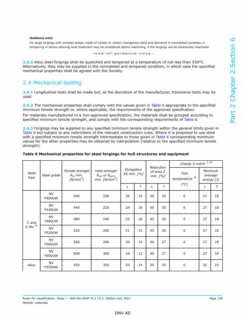
Guidance note:For large forgings with complex shape, made of carbon or carbon-manganese steel and delivered in normalised condition, atempering or stress relieving heat treatment may be considered before machining, if the forgings will be extensively machined.
---e-n-d---o-f---g-u-i-d-a-n-c-e---n-o-t-e---
2.3.2 Alloy steel forgings shall be quenched and tempered at a temperature of not less than 550°C.Alternatively, they may be supplied in the normalised and tempered condition, in which case the specifiedmechanical properties shall be agreed with the Society.
2.4 Mechanical testing
2.4.1 Longitudinal tests shall be made but, at the discretion of the manufacturer, transverse tests may beused.
2.4.2 The mechanical properties shall comply with the values given in Table 6 appropriate to the specifiedminimum tensile strength or, where applicable, the requirements of the approved specification.For materials manufactured to a non-approved specification, the materials shall be grouped according tospecified minimum tensile strength, and comply with the corresponding requirements of Table 6.
2.4.3 Forgings may be supplied to any specified minimum tensile strength within the general limits given inTable 6 but subject to any restrictions of the relevant construction rules. Where it is proposed to use steelwith a specified minimum tensile strength intermediate to those given in Table 6 corresponding minimumvalues for the other properties may be obtained by interpolation (relative to the specified minimum tensilestrength).
Table 6 Mechanical properties for steel forgings for hull structures and equipment
Charpy V-notch 1, 2)
ElongationA5 min. [%]
Reductionof area Zmin. [%]
Minimumaverageenergy [J]
Steeltype Steel grade
Tensile strengthRm min.[N/mm2]
Yield strengthReH or Rp0.2min. [N/mm2]
L T L T
Test
temperature 3)
[°C]L T
NVF400UW 400 200 26 19 50 35 0 27 18
NVF440UW 440 220 24 18 50 35 0 27 18
NVF480UW 480 240 22 16 45 30 0 27 18
NVF520UW 520 260 21 15 45 30 0 27 18
NVF560UW 560 280 20 14 40 27 0 27 18
C andC-Mn 4)
NVF600UW 600 300 18 13 40 27 0 27 18
AlloyNV
F550AW 550 350 20 14 50 35 0 32 22
Part 2 Chapter 2 Section 6
Rules for classification: Ships — DNV-RU-SHIP Pt.2 Ch.2. Edition July 2021 Page 129Metallic materials
DNV AS

NVF600AW 600 400 18 13 50 35 0 32 22
NVF650AW 650 450 17 12 50 35 0 32 22
1) Testing at +20°C may be accepted subject to compliance with a specified minimum average energy of 45 Jlongitudinal or 30 J transverse for all grades. L = longitudinal, T = transverse/tangential.
2) Test direction shall follow the requirements of [1.9].3) Stricter requirements overruling above requirements are given in the relevant design and construction rules for
some applications, e.g. windlass components and polar class ships. Unless specified otherwise in the applicabledesign rule or standard, forgings in structural members subject to lower design temperatures than -10ºC shall beimpact tested at 5ºC below the design temperature.
4) For ships with class notation DAT forgings with maximum 0.80% Ni but otherwise complying with the compositionlimits of C and C-Mn steels, may follow the yield, tensile and elongation properties requirements for C and C-Mnsteels. For impact toughness requirements, see relevant design and construction rules.
2.5 Inspection
2.5.1 Magnetic particle (MT) or liquid penetrant testing (PT) shall be carried out on finished machinedforgings intended for rudder stocks and pintles with diameter larger than 100 mm, see [1.12.6].
2.5.2 Ultrasonic testing shall be carried out on forgings intended for rudder stocks and pintles with diameterlarger than 200 mm.
3 Forgings for shafting and machinery
3.1 Scope
3.1.1 These requirements are supplementary to [1] and apply to steel forgings intended for shafting andmachinery construction which are not within the scope of [4] and [5]. Provision is made for carbon andcarbon-manganese steels and alloy steels.
3.1.2 Where stainless steel forgings are intended for machinery application, see [8.1.3].
3.1.3 Forgings intended for welding shall either comply with both the chemical composition and mechanicalproperties requirements given in [2], or just by the chemical composition requirements of [2] but themechanical properties requirements given in Table 8. For the latter case, the naming of the grade shall beaccording to Table 8, where the grade name may be appended with MW in brackets, e.g. NV F600U(MW).
3.2 Chemical composition
3.2.1 The chemical composition shall comply with the overall limits given in Table 7 or, where applicable, therequirements of the approved specification.
Table 7 Chemical composition limits 1) for steel forgings for shafting and machinery 2)
Steel type C Si Mn P S Cr 3) Mo 3) Ni 3) Cu 3) Totalresiduals
Part 2 Chapter 2 Section 6
Rules for classification: Ships — DNV-RU-SHIP Pt.2 Ch.2. Edition July 2021 Page 130Metallic materials
DNV AS

C and C-Mn 0.65 0.45 0.30 to1.50 0.035 0.035 0.30 0.15 0.40 0.30 0.85
Alloy 0.45 0.45 0.30 to1.00 0.035 0.035 Minimum
0.40 4)Minimum0.15 4)
Minimum0.40 4) 0.30 -
1) Given value is maximum content ([%] by weight) unless shown as a range or as a minimum.2) Other specifications may also be approved, see [1.1.3].3) Elements are considered as residual elements unless shown as a range or as a minimum.4) One or more of the elements shall comply with the minimum content.
3.3 Heat treatment
3.3.1 Carbon and carbon-manganese steel forgings shall be supplied in one of the following conditions:
a) fully annealedb) normalisedc) normalised and tempered at a temperature of not less than 550°Cd) quenched and tempered at a temperature of not less than 550°C.
3.3.2 Alloy steel forgings shall be quenched and tempered at a temperature of not less than 550°C.Alternatively, they may be supplied in the normalised and tempered condition, in which case the specifiedmechanical properties shall be agreed with the Society.
3.3.3 Where forgings for gearing are not intended for surface hardening, lower tempering temperature maybe accepted.
3.4 Mechanical testing
3.4.1 Longitudinal tests shall be made but, at the discretion of the manufacturer, alternative tests as shownin Figure 1 to Figure 3 may be used. For shafts with keyways, splines, radial holes, slots etc., tangential testsshall be made provided the shape and dimensions make it possible.
3.4.2 The mechanical properties shall comply with the values given in Table 8 appropriate to the specifiedminimum tensile strength or, where applicable, the requirements of the approved specification.
3.4.3 Forgings may be supplied to any specified minimum tensile strength within the general limits given inTable 8 but subject to any restrictions of the relevant construction rules. Where it is proposed to use a steelwith a specified minimum tensile strength intermediate to those given in Table 8, corresponding minimumvalues for the other properties may be obtained by interpolation (relative to the specified minimum tensilestrength).
Table 8 Mechanical properties for steel forgings for shafting and machinery
ElongationA5 min. [%]
Reductionof area Zmin. [%]
Charpy V-notch 1, 2, 3, 4,5) energy, min.average [J]
Steel type Steel gradeTensile strength
Rm min.[N/mm²]
Yield strengthReH or Rp0.2min. [N/mm²]
L T L T L T
NV F400U 400 200 26 19 50 35 32 18C and C-Mn
NV F440U 440 220 24 18 50 35 30 18
Part 2 Chapter 2 Section 6
Rules for classification: Ships — DNV-RU-SHIP Pt.2 Ch.2. Edition July 2021 Page 131Metallic materials
DNV AS

NV F480U 480 240 22 16 45 30 26 14
NV F520U 520 260 21 15 45 30 24 13
NV F560U 560 280 20 14 40 27 23 12
NV F600U 600 300 18 13 40 27 18 12
NV F640U 640 320 17 12 40 27 18 12
NV F680U 680 340 16 12 35 24 18 12
NV F720U 720 360 15 11 35 24 18 12
NV F760U 760 380 14 10 35 24 18 12
NV F600A 600 360 18 14 50 35 41 24
NV F700A 700 420 16 12 45 30 32 22
NV F800A 800 480 14 10 40 27 32 22
NV F900A 900 630 13 9 40 27 27 18
NV F1000A 1000 700 12 8 35 24 25 16
Alloy
NV F1100A 1100 770 11 7 35 24 21 13
1) Testing temperature is +20°C unless otherwise specified (see also note 2).2) Forgings for cold climate application in accordance with Pt.6 Ch.6 shall follow the requirements given therein.3) materials of essential components exposed to low air temperature shall be tested at 10°C below the lowest design
temperature, unless otherwise approved or specified in the relevant design and construction rules, such as Pt.4 Ch.1Sec.3 [2.2] and Pt.6 Ch.6. The obtained average energy shall be ≥ 27 J.
4) Test direction shall follow the requirements of [1.9].5) L = longitudinal, T = transverse/tangential.
3.5 Inspection
3.5.1 Magnetic particle (MT) or liquid penetrant testing (PT) of finished machined forgings shall be carriedout as specified in the relevant construction rules.
3.5.2 Ultrasonic testing (UT) of forgings shall be carried out as specified in the relevant construction rules.
Figure 1 Plain shaft
Part 2 Chapter 2 Section 6
Rules for classification: Ships — DNV-RU-SHIP Pt.2 Ch.2. Edition July 2021 Page 132Metallic materials
DNV AS

Figure 2 Flanged shaft
Figure 3 Flanged shaft with collar
4 Forgings for crankshafts
4.1 Scope
4.1.1 These requirements are supplementary to [1] and apply to materials for solid forged crankshafts andto the forged throws, webs and pins of semi-built crankshafts. Provision is made for carbon and carbon-manganese steels and alloy steels. In case clean steel forgings shall be manufactured, the requirements asspecified in [1.6.10] are applicable.
4.2 Chemical composition
4.2.1 The chemical composition shall comply with the overall limits given in Table 7 or, where applicable, therequirements of the approved specification.
Part 2 Chapter 2 Section 6
Rules for classification: Ships — DNV-RU-SHIP Pt.2 Ch.2. Edition July 2021 Page 133Metallic materials
DNV AS

4.3 Heat treatment
4.3.1 Carbon and carbon-manganese steel forgings shall be supplied in one of the following conditions:
— normalised and tempered at a temperature of not less than 550°C— quenched and tempered at a temperature of not less than 550°C.
4.3.2 Alloy steel forgings shall be quenched and tempered at a temperature of not less than 550°C.Alternatively, they may be supplied in the normalised and tempered condition, in which case the specifiedmechanical properties shall be agreed with the Society.
4.4 Mechanical testing
4.4.1 For solid forged crankshafts, one set of longitudinal tests shall be taken from the driving shaft end ofeach forging (one of the longitudinal specimen in Figure 4). Where the mass (as heat-treated but excludingtest material) exceeds 3 tonnes, a second set of tests shall be taken from the opposite end (i.e. bothlongitudinal specimens in Figure 4). Where, the crank throws are formed by machining or flame cutting froma pre-forged crankshaft, see also [1.6.6], the second set of tests shall be taken in a tangential direction frommaterial removed from the crank throw at the end opposite the driving shaft end (indicated as transversespecimen in Figure 4). For this test, the material affected by the flame cutting (heat affected zone) shall becompletely removed by machining. This rule does not apply to webs which are cut out of the starting materialbefore the specified heat treatment is applied.
4.4.2 For crankthrow forgings and other forgings where the method of manufacture has been speciallyapproved in accordance with [1.6], the number and position of the tests shall be agreed.
4.4.3 Forgings with mass up to 500 kg each may be batch tested in accordance with [1.10]. For normalisedforgings, one set of mechanical test are required for each test unit. For quenched and tempered forgings, twosets are required for each test unit.
4.4.4 The mechanical properties shall comply with the values given in Table 8 appropriate to the specifiedminimum tensile strength or, where applicable, the requirements of the approved specification.
4.4.5 For forgings which have been batch tested, hardness tests shall be made on at least 10% of theforgings. For the hardness testing, its testing method, position, acceptance criteria shall be agreed with theSociety.
4.5 Inspection
4.5.1 Magnetic particle or liquid penetrant testing of finished machined crankshafts shall be carried out asspecified in Pt.4 Ch.3 Sec.1 [3].
4.5.2 Ultrasonic testing of crankshafts shall be carried out as specified in Pt.4 Ch.3 Sec.1 [3].Part 2 Chapter 2 Section 6
Rules for classification: Ships — DNV-RU-SHIP Pt.2 Ch.2. Edition July 2021 Page 134Metallic materials
DNV AS

Figure 4 Solid forged crankshaft
5 Forgings for gearing
5.1 Scope
5.1.1 These requirements are supplementary to [1] and apply to steel forgings intended for use inthe construction of gearing such as pinions, gear wheels and rims, etc. intended for the drivers andpower transmission. Provision is made for carbon and carbon-manganese steels and alloy steels. Specialrequirements for clean steel forgings are given in [1.6.10].Requirements for surface hardening, e.g. carburizing, induction hardening and nitriding, is given in Pt.4 Ch.4Sec.2 [3].
Guidance note:Heat treatment and/or mechanical testing may be performed by the forge or the gear manufacturer.
---e-n-d---o-f---g-u-i-d-a-n-c-e---n-o-t-e---
5.2 Chemical composition
5.2.1 The chemical composition shall comply with the overall limits given in Table 7 or, where applicable, therequirements of the approved specification.
5.3 Heat treatment
5.3.1 Carbon and carbon-manganese steel forgings not intended for carburising shall be supplied in one ofthe following conditions:
— normalised and tempered— quenched and tempered.
Part 2 Chapter 2 Section 6
Rules for classification: Ships — DNV-RU-SHIP Pt.2 Ch.2. Edition July 2021 Page 135Metallic materials
DNV AS
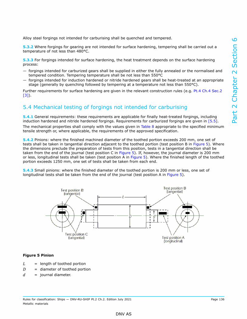
Alloy steel forgings not intended for carburising shall be quenched and tempered.
5.3.2 Where forgings for gearing are not intended for surface hardening, tempering shall be carried out atemperature of not less than 480°C.
5.3.3 For forgings intended for surface hardening, the heat treatment depends on the surface hardeningprocess:
— forgings intended for carburized gears shall be supplied in either the fully annealed or the normalised andtempered condition. Tempering temperature shall be not less than 550°C
— forgings intended for induction hardened or nitride hardened gears shall be heat-treated at an appropriatestage (generally by quenching followed by tempering at a temperature not less than 550°C).
Further requirements for surface hardening are given in the relevant construction rules (e.g. Pt.4 Ch.4 Sec.2[3]).
5.4 Mechanical testing of forgings not intended for carburising
5.4.1 General requirements: these requirements are applicable for finally heat-treated forgings, includinginduction hardened and nitride hardened forgings. Requirements for carburized forgings are given in [5.5].The mechanical properties shall comply with the values given in Table 8 appropriate to the specified minimumtensile strength or, where applicable, the requirements of the approved specification.
5.4.2 Pinions: where the finished machined diameter of the toothed portion exceeds 200 mm, one set oftests shall be taken in tangential direction adjacent to the toothed portion (test position B in Figure 5). Wherethe dimensions preclude the preparation of tests from this position, tests in a tangential direction shall betaken from the end of the journal (test position C in Figure 5). If, however, the journal diameter is 200 mmor less, longitudinal tests shall be taken (test position A in Figure 5). Where the finished length of the toothedportion exceeds 1250 mm, one set of tests shall be taken from each end.
5.4.3 Small pinions: where the finished diameter of the toothed portion is 200 mm or less, one set oflongitudinal tests shall be taken from the end of the journal (test position A in Figure 5).
Figure 5 Pinion
L = length of toothed portionD = diameter of toothed portiond = journal diameter.
Part 2 Chapter 2 Section 6
Rules for classification: Ships — DNV-RU-SHIP Pt.2 Ch.2. Edition July 2021 Page 136Metallic materials
DNV AS

5.4.4 Gear wheels: one set of tangential tests shall be taken, see Figure 6. Where the finished diameterexceeds 2500 mm tests shall be taken from two diametrically opposite positions.
Figure 6 Gear wheel
5.4.5 Gear wheel rims (made by expanding): one set of tangential tests shall be taken from one of the testpositions A in Figure 7. Where the finished diameter exceeds 2500 mm or the mass (as heat-treated butexcluding test material) exceeds 3 tonnes, tests shall be taken from two diametrically opposite positions.
Figure 7 Gear rim (made by expanding)
5.4.6 Hollow pinions: one set of tangential tests shall be taken (test position A in Figure 8). Where thefinished length of the toothed portion exceeds 1250 mm, tests shall be taken from each end.
Part 2 Chapter 2 Section 6
Rules for classification: Ships — DNV-RU-SHIP Pt.2 Ch.2. Edition July 2021 Page 137Metallic materials
DNV AS

Guidance note:For hollow pinions forged as solid blanks and then drilled/machined, the tangential sample will be transverse to the grain flow,and the requirements for tangential direction given in Table 8 apply. For hollow pinions produced by piercing a blank followed byring rolling/forging (expanding) over a mandrel, the tangential sample will be parallel to the grain flow and the requirements forlongitudinal direction given in Table 8 apply.
---e-n-d---o-f---g-u-i-d-a-n-c-e---n-o-t-e---
Figure 8 Hollow pinion
5.4.7 Batch testing of small forgings: for forgings which have been batch tested in accordance with [1.10],at least one hardness test shall be made on each forging. The variation in hardness in each batch shall notexceed the values specified in Table 9.
Table 9 Permitted Brinell hardness variation
Specified minimum tensile strength Rm, [MPa] Accepted maximum difference in hardness [Brinell]
< 600 25
600 ≤ Rm < 900 35
≥ 900 42
5.4.8 Mechanical properties for small forgings: the mechanical properties shall comply with the values givenin Table 8 appropriate to the specified minimum tensile strength or, where applicable, the requirements of theapproved specification.
5.5 Testing of forgings intended for carburising
5.5.1 When forgings shall be carburised, sufficient test material shall be provided both for preliminary testsat the forge and for final tests after completion of carburising.For this purpose at least duplicate sets of test material shall be taken from positions as detailed in [5.4].Exception from this is given for forgings with integral journals where one set of test specimens is accepted(irrespective of the dimensions or mass of the forging). The latter shall be cut in a longitudinal direction.The test material shall be machined to a diameter of D/4 or 60 mm, whichever is less, where D is thefinished diameter of the toothed portion.For preliminary tests at the forge one set of test material shall be given a blank carburizing and heattreatment cycle simulating that which subsequently will be applied to the forging.For final acceptance tests, the second set of test material shall be blank carburized and heat-treated alongwith the forgings which they represent.At the discretion of the forgemaster or gear manufacturer, test samples of larger cross section may beeither carburized or blank carburized, but these shall be machined to the required diameter prior to the
Part 2 Chapter 2 Section 6
Rules for classification: Ships — DNV-RU-SHIP Pt.2 Ch.2. Edition July 2021 Page 138Metallic materials
DNV AS

final quenching and tempering heat treatment. Alternative procedures for testing of forgings which shall becarburized may be specially agreed with the Society.The mechanical properties shall comply with the values given in Table 8 appropriate to the specified minimumtensile strength or, where applicable, the requirements of the approved specification.
5.5.2 Requirements for the carburizing are given in the relevant rules, see e.g. Pt.4 Ch.4 Sec.2 [3].
5.6 Inspection
5.6.1 Magnetic particle or liquid penetrant testing of finished machined forgings shall be carried out asspecified in Pt.4 Ch.4 Sec.2 [3].
5.6.2 Ultrasonic testing of forgings shall be carried out as specified in Pt.4 Ch.4 Sec.2 [3].
6 Forgings for boilers, pressure vessels and piping systems
6.1 Scope
6.1.1 These requirements are supplementary to [1] and apply to steel forgings intended for boilers, pressurevessels and piping systems such as flanges, nozzles, valve housings, socket welding and welding neckcomponents etc., where the design temperature is not lower than 0°C. Provision is made for carbon andcarbon-manganese steels and alloy steels.Requirements for forgings for pressure vessel and piping for cold climate is given in Pt.6 Ch.6.
6.2 Chemical composition
6.2.1 The chemical composition shall comply with the overall limits given in Table 10 10 or, where applicable,the requirements of the approved specification.
Table 10 Chemical composition limits 1) for steel forgings for boilers, pressure vessels and pipingsystems
Steeltype
Steelgrade C Si Mn P S Cr2) Mo2) Ni2) Cu2) Al3)
NVF450HC and
C-Mn 4) NVF490H
0.23
0.15
-
0.40
0.50
-
1.60
0.030 0.030 0.30 0.15 0.40 0.30
0.02
-
0.05
NVF0.5Mo 0.23
0.50
-
0.90
0.30
Alloy
NV F1Cr0.5Mo
0.20
0.15
-
0.40 0.30
-
0.80
0.030 0.0300.80
-
1.25
0.45
-
0.65
0.40 0.30 0.02
Part 2 Chapter 2 Section 6
Rules for classification: Ships — DNV-RU-SHIP Pt.2 Ch.2. Edition July 2021 Page 139Metallic materials
DNV AS
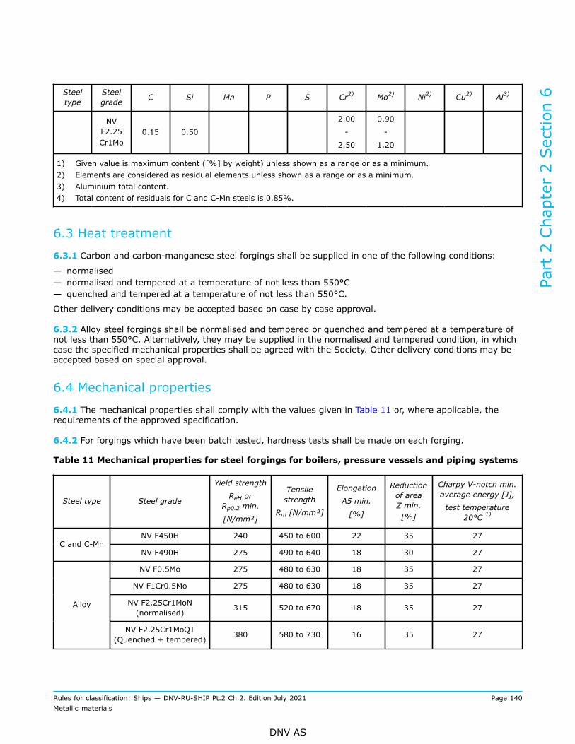
Steeltype
Steelgrade C Si Mn P S Cr2) Mo2) Ni2) Cu2) Al3)
NVF2.25Cr1Mo
0.15 0.50
2.00
-
2.50
0.90
-
1.20
1) Given value is maximum content ([%] by weight) unless shown as a range or as a minimum.2) Elements are considered as residual elements unless shown as a range or as a minimum.3) Aluminium total content.4) Total content of residuals for C and C-Mn steels is 0.85%.
6.3 Heat treatment
6.3.1 Carbon and carbon-manganese steel forgings shall be supplied in one of the following conditions:
— normalised— normalised and tempered at a temperature of not less than 550°C— quenched and tempered at a temperature of not less than 550°C.
Other delivery conditions may be accepted based on case by case approval.
6.3.2 Alloy steel forgings shall be normalised and tempered or quenched and tempered at a temperature ofnot less than 550°C. Alternatively, they may be supplied in the normalised and tempered condition, in whichcase the specified mechanical properties shall be agreed with the Society. Other delivery conditions may beaccepted based on special approval.
6.4 Mechanical properties
6.4.1 The mechanical properties shall comply with the values given in Table 11 or, where applicable, therequirements of the approved specification.
6.4.2 For forgings which have been batch tested, hardness tests shall be made on each forging.
Table 11 Mechanical properties for steel forgings for boilers, pressure vessels and piping systems
Steel type Steel grade
Yield strength
ReH orRp0.2 min.
[N/mm²]
Tensilestrength
Rm [N/mm²]
Elongation
A5 min.
[%]
Reductionof areaZ min.[%]
Charpy V-notch min.average energy [J],
test temperature20°C 1)
NV F450H 240 450 to 600 22 35 27C and C-Mn
NV F490H 275 490 to 640 18 30 27
NV F0.5Mo 275 480 to 630 18 35 27
NV F1Cr0.5Mo 275 480 to 630 18 35 27
NV F2.25Cr1MoN(normalised) 315 520 to 670 18 35 27Alloy
NV F2.25Cr1MoQT(Quenched + tempered) 380 580 to 730 16 35 27
Part 2 Chapter 2 Section 6
Rules for classification: Ships — DNV-RU-SHIP Pt.2 Ch.2. Edition July 2021 Page 140Metallic materials
DNV AS
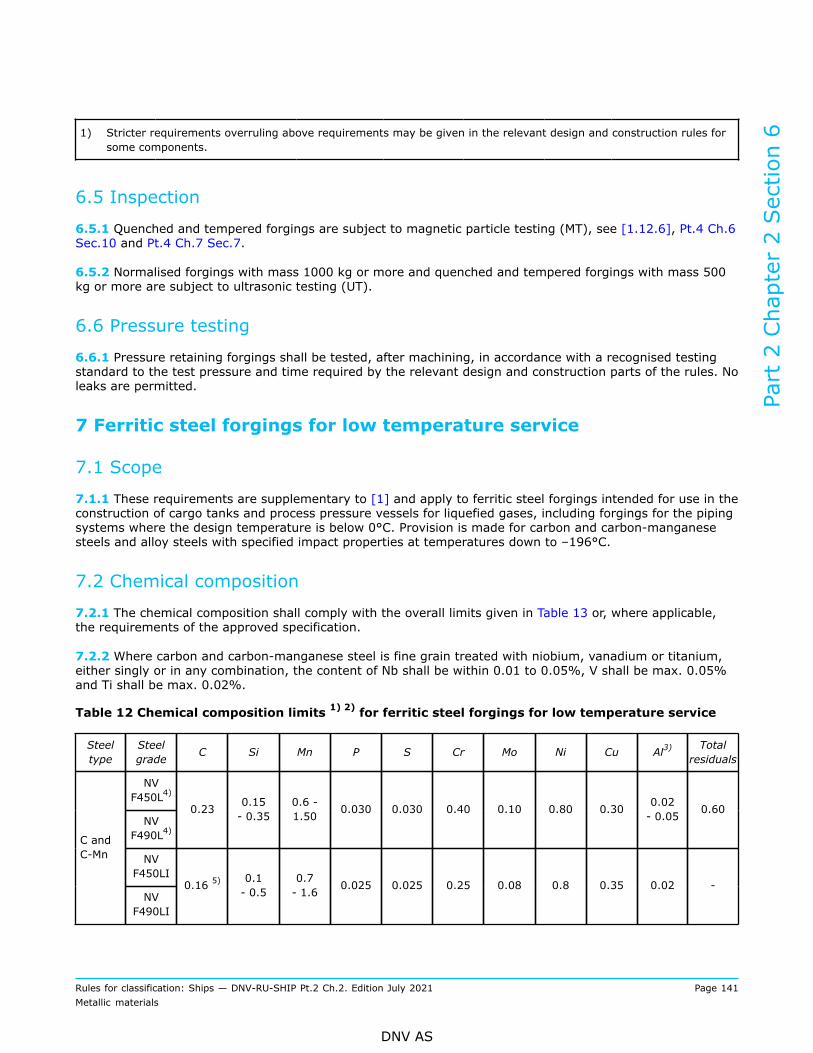
1) Stricter requirements overruling above requirements may be given in the relevant design and construction rules forsome components.
6.5 Inspection
6.5.1 Quenched and tempered forgings are subject to magnetic particle testing (MT), see [1.12.6], Pt.4 Ch.6Sec.10 and Pt.4 Ch.7 Sec.7.
6.5.2 Normalised forgings with mass 1000 kg or more and quenched and tempered forgings with mass 500kg or more are subject to ultrasonic testing (UT).
6.6 Pressure testing
6.6.1 Pressure retaining forgings shall be tested, after machining, in accordance with a recognised testingstandard to the test pressure and time required by the relevant design and construction parts of the rules. Noleaks are permitted.
7 Ferritic steel forgings for low temperature service
7.1 Scope
7.1.1 These requirements are supplementary to [1] and apply to ferritic steel forgings intended for use in theconstruction of cargo tanks and process pressure vessels for liquefied gases, including forgings for the pipingsystems where the design temperature is below 0°C. Provision is made for carbon and carbon-manganesesteels and alloy steels with specified impact properties at temperatures down to –196°C.
7.2 Chemical composition
7.2.1 The chemical composition shall comply with the overall limits given in Table 13 or, where applicable,the requirements of the approved specification.
7.2.2 Where carbon and carbon-manganese steel is fine grain treated with niobium, vanadium or titanium,either singly or in any combination, the content of Nb shall be within 0.01 to 0.05%, V shall be max. 0.05%and Ti shall be max. 0.02%.
Table 12 Chemical composition limits 1) 2) for ferritic steel forgings for low temperature service
Steeltype
Steelgrade C Si Mn P S Cr Mo Ni Cu Al3) Total
residuals
NVF450L4)
NVF490L4)
0.23 0.15- 0.35
0.6 -1.50 0.030 0.030 0.40 0.10 0.80 0.30 0.02
- 0.05 0.60
NVF450LI
C andC-Mn
NVF490LI
0.16 5) 0.1- 0.5
0.7- 1.6 0.025 0.025 0.25 0.08 0.8 0.35 0.02 -
Part 2 Chapter 2 Section 6
Rules for classification: Ships — DNV-RU-SHIP Pt.2 Ch.2. Edition July 2021 Page 141Metallic materials
DNV AS
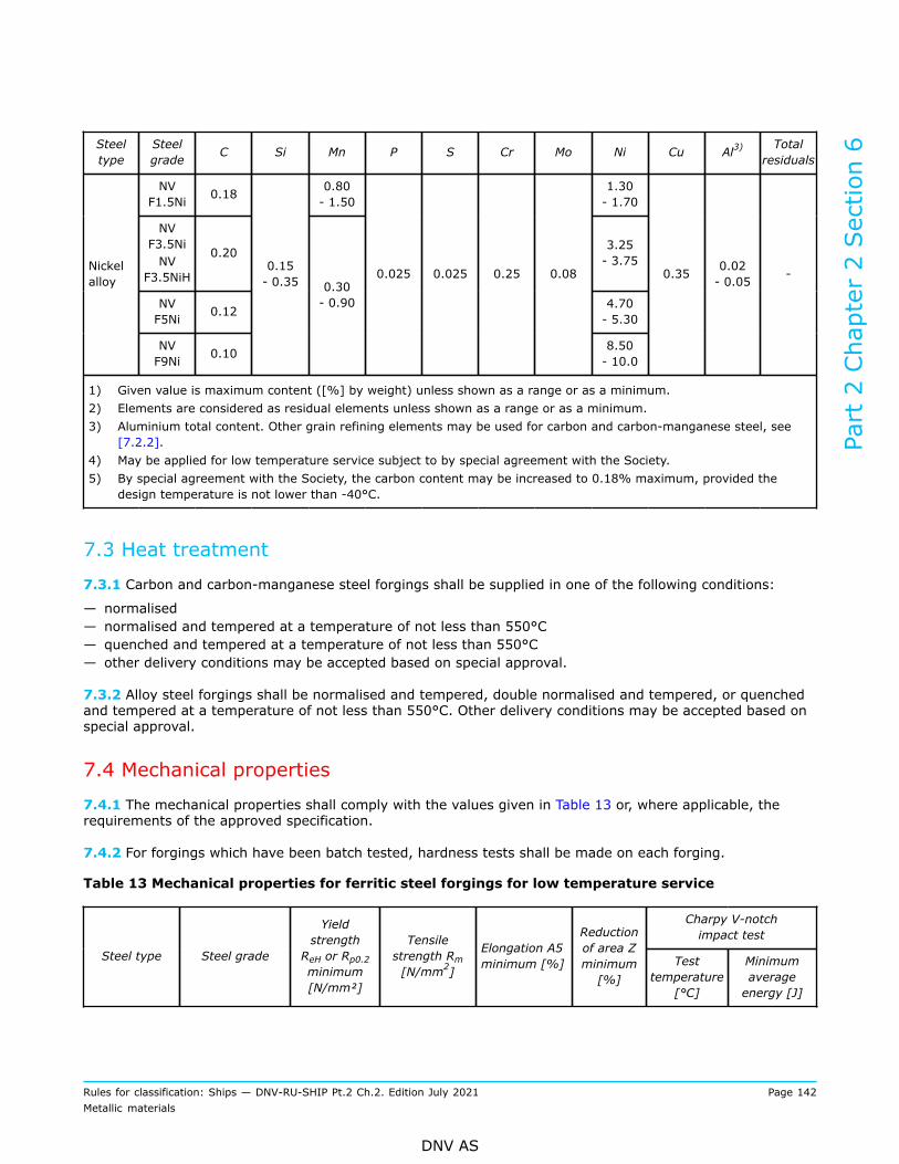
Steeltype
Steelgrade C Si Mn P S Cr Mo Ni Cu Al3) Total
residuals
NVF1.5Ni 0.18 0.80
- 1.501.30- 1.70
NVF3.5NiNV
F3.5NiH
0.20 3.25- 3.75
NVF5Ni 0.12 4.70
- 5.30
Nickelalloy
NVF9Ni 0.10
0.15- 0.35 0.30
- 0.90
0.025 0.025 0.25 0.08
8.50- 10.0
0.35 0.02- 0.05 -
1) Given value is maximum content ([%] by weight) unless shown as a range or as a minimum.2) Elements are considered as residual elements unless shown as a range or as a minimum.3) Aluminium total content. Other grain refining elements may be used for carbon and carbon-manganese steel, see
[7.2.2].4) May be applied for low temperature service subject to by special agreement with the Society.5) By special agreement with the Society, the carbon content may be increased to 0.18% maximum, provided the
design temperature is not lower than -40°C.
7.3 Heat treatment
7.3.1 Carbon and carbon-manganese steel forgings shall be supplied in one of the following conditions:
— normalised— normalised and tempered at a temperature of not less than 550°C— quenched and tempered at a temperature of not less than 550°C— other delivery conditions may be accepted based on special approval.
7.3.2 Alloy steel forgings shall be normalised and tempered, double normalised and tempered, or quenchedand tempered at a temperature of not less than 550°C. Other delivery conditions may be accepted based onspecial approval.
7.4 Mechanical properties
7.4.1 The mechanical properties shall comply with the values given in Table 13 or, where applicable, therequirements of the approved specification.
7.4.2 For forgings which have been batch tested, hardness tests shall be made on each forging.
Table 13 Mechanical properties for ferritic steel forgings for low temperature service
Charpy V-notchimpact test
Steel type Steel grade
YieldstrengthReH or Rp0.2minimum[N/mm²]
Tensilestrength Rm[N/mm2]
Elongation A5minimum [%]
Reductionof area Zminimum[%]
Testtemperature
[°C]
Minimumaverageenergy [J]
Part 2 Chapter 2 Section 6
Rules for classification: Ships — DNV-RU-SHIP Pt.2 Ch.2. Edition July 2021 Page 142Metallic materials
DNV AS

NV F450L 1) 240 450 to 600 22 40 -60 2) 27
NV F490L 1) 275 490 to 640 20 40 -60 2) 27
NV F450LI 240 450 to 600 22 40 -60 2) 41C and C-Mn
NV F450LI 275 490 to 640 20 40 -60 2) 41
NV F1.5Ni 345 470 to 640 22 35 -65 41 3)
NV F3.5Ni 275 490 to 640 20 35 -95 41 3)
NV F3.5NiH 345 490 to 640 20 35 -95 41 3)
NV F5Ni 380 540 to 690 20 35 -110 41 3)Nickel alloy
NV F9Ni 480 640 to 790 18 35 -196 41 3)
1) May be applied for low temperature service subject to approval by the Society.2) Applicable for design temperature -55°C or higher. For material thickness (t), test temperature may alternatively be:
— t ≤ 25 mm: 5°C below the design temperature or –20°C, whichever is lower— 25 mm < t ≤ 30 mm: 10°C below design temperature or -20°C, whichever is lower— 30 mm < t ≤ 35 mm: 15°C below design temperature or -20°C, whichever is lower— 35 mm < t ≤ 40 mm: 20°C below design temperature— t > 40 mm: test temperature shall be approved by the Society.
3) Minimum average energy of 34 J may be accepted subject to approval by the Society.
7.5 Inspection
7.5.1 Quenched and tempered forgings are subject to magnetic particle testing (MT), see [1.12.6] and therelevant construction rules.
7.5.2 Normalised forgings with mass 1000 kg or more and quenched and tempered forgings with mass 500kg or more are subject to ultrasonic testing (UT).
7.6 Pressure testing
7.6.1 Pressure retaining forgings shall be tested after machining to the test pressure required by therelevant design and construction parts of the rules. No leaks are permitted.
8 Stainless steel forgings
8.1 Scope
8.1.1 These requirements are supplementary to [1] and apply to martensitic, martensitic-austenitic,precipitation hardened, ferritic, duplex (ferritic/austenitic) and austenitic stainless steel forgings, includingaustenitic steel forgings intended for use in the construction of cargo tanks and piping systems for liquefiedgases and chemicals.
8.1.2 Stainless steel forgings shall be in accordance with recognised standards, e.g. EN 10222, ASTM A473,ASTM A965, ASTM A1049 and JIS G 3214, provided that supplementary requirements contained herein arealso met. Recognition of other standards is subject to submission to the Society for evaluation, see Ch.1Sec.1 [3.4].
Part 2 Chapter 2 Section 6
Rules for classification: Ships — DNV-RU-SHIP Pt.2 Ch.2. Edition July 2021 Page 143Metallic materials
DNV AS
8.1.3 Where stainless steel forgings are intended for machinery application, particulars of chemicalcomposition, mechanical properties, heat treatment, non-destructive testing and repair shall be submitted inconnection with the approval of the design for which the material is proposed.
8.1.4 Design temperature shall in general follow the requirements of the applicable design rules. Unlessindicated otherwise in the applicable design rules, the following limits apply, and design temperatures outsidethe given limits are subject to special consideration and approval.The austenitic steels may be used for pressure retaining applications where the design temperature isnot lower than -165°C. Limitation to upper temperature for austenitic steels shall be assessed based onhigh temperature properties, also considering corrosion in the applicable environment of exposure. Duplex(ferritic/austenitic) stainless steels may be used for pressure retaining applications where the designtemperature is not lower than -46°C, and not higher than 100°C/110°C if exposed to saliferous atmospherefor UNS S31803/UNS S32750, respectively. Design temperatures outside these ranges are subject toapproval.
8.2 Manufacture
8.2.1 Steel shall be manufactured by an electric or one of the basic oxygen processes or any other processinvolving secondary refining approved by the Society.
8.3 Mechanical properties
8.3.1 Charpy V-notch impact testing is required as specified in the relevant structural design standard.Unless otherwise specified, testing shall be carried out at 5°C below the design temperature. Unlessotherwise specified in the referring rules, impact testing of austenitic stainless steel is required where thedesign temperature is below –105°C and testing shall be carried out at –196°C. Average energy value shallbe minimum 41 J for longitudinal tests and 34 J for tangential tests, respectively.
8.4 Inspection
8.4.1 Forgings with mass 1000 kg or more are subject to ultrasonic testing.
9 Bolts and nuts
9.1 Scope9.1.1 GeneralWhere required by the relevant design and construction parts of the rules, bolts and nuts shall comply withthe requirements of Ch.1, the general requirements of Sec.1 and [1] and this subsection. This subsectionspecifies the requirements for bolts and nuts to be used in essential equipment e.g.:
— boilers, pressure vessels, equipment and pipelines— diesel engines, gears, shafting and propellers— rudder couplings— other components for which proof of quality is required as specified in the rules.
Provision is made for carbon and carbon-manganese, alloy, and stainless steels.
9.1.2 Reference to other rule partsThe choice of bolts and nuts, together with the form of the requisite material test certificate is set out in theindividual chapters of the rules. Specific or additional requirements may be provided in other parts of the
Part 2 Chapter 2 Section 6
Rules for classification: Ships — DNV-RU-SHIP Pt.2 Ch.2. Edition July 2021 Page 144Metallic materials
DNV AS
Society's rules and standards. In case of conflicting requirements, the specific or additional requirementsgiven by the referring rules are prevailing.Requirements for bolts and nuts not covered by this section, as well as for washers, shall comply with therelevant design rules.
9.1.3 Bolts and nuts with threads up to M39For finished bolts and nuts with threads up to M39 all the requirements of one of the following standards areapplicable, with the additional requirements given in [9.5] and [9.6]:
— [1] to [8] of Sec.6— ISO 898-1 and ISO 898-2. Exempted thereof are bolts of strength categories for which the standard givesno data in respect of impact energy
— ISO 3506-1 and ISO 3506-2 for stainless steel fasteners.Guidance note:Bolts and nuts complying with other standards may be accepted provided proved suitable for the intended application.
---e-n-d---o-f---g-u-i-d-a-n-c-e---n-o-t-e---
9.1.4 Bolts and nuts with threads exceeding M39For finished bolts and nuts with threads exceeding M39 the relevant requirements of [9.2] to [9.8] areapplicable.
9.2 Materials
9.2.1 Materials for bolts and nuts shall be in accordance with recognised standards, as given in [9.2.2].Recognition of other standards is subject to submission to the Society for evaluation.
9.2.2 Materials for bolts and nuts shall be in accordance with one of the following standards, or a standardrecognized by the Society, see also guidance note and [9.2.3]:
— Pt.2 Ch.2 Sec.6 [2] to [8]— ISO 898-1 and -2 up to and including M39 threads. Exempted thereof are bolts of strength categories forwhich the standard gives no data in respect of impact energy
— ISO 3506-1 and -2 for stainless steel fasteners— steels conforming to EN 10269.
For materials for bolts intended for pressure equipment additional requirements are specified in [9.6.3]Guidance note:Bolt and nut materials complying with other standards may be accepted by the Society provided the materials are provedsuitable for the intended application. As an example, materials in accordance with DIN 267-13 may be accepted for general, lowtemperature and elevated temperature application.
---e-n-d---o-f---g-u-i-d-a-n-c-e---n-o-t-e---
9.2.3 Where the use of material with differing requirements is proposed conforming to other standards orthe manufacturer’s material specifications, particulars shall be submitted in connection with the approval ofthe design for which the material is proposed. As a minimum, the following particulars shall be specified foralternative materials:
— relevant standard/specification and grade— manufacturing process— chemical composition— heat treatment/delivery condition— test units and number of tests— mechanical properties: unless otherwise specified, the materials shall satisfy the requirements of [9.6]— inspection including non-destructive testing.
Part 2 Chapter 2 Section 6
Rules for classification: Ships — DNV-RU-SHIP Pt.2 Ch.2. Edition July 2021 Page 145Metallic materials
DNV AS

Further particulars may be required as relevant for the approval. Requirements for approval of manufacturerand certification of materials shall follow Ch.1.
9.3 Manufacture
9.3.1 Bolts and nuts shall be manufactured by hot or cold forming such as pressing, or rolled/forged barswith subsequent machining and/or rolling of threads according to a recognized standard.Surface smoothing and rolling of the thread are not regarded as cold forming within the meaning of thisparagraph.
9.3.2 For the manufacture of bolts and nuts with threads up to and including M39 the requirements given inthe standards in [9.2.2] are applicable.
9.3.3 For bolts and nuts with threads exceeding M39 forged semi-finished products shall be used.
9.3.4 Bolts and nuts shall be in the heat-treated condition specified for the material. The material shall notundergo unacceptable embrittlement up to the maximum temperature occurring in service. Bolts for sub-zerotemperatures, shall exhibit adequate toughness. In the case of quenched and tempered steels, the temperingtemperature shall be sufficiently higher than the maximum in-service temperature in order to avoid strengthreduction.
9.3.5 Cold formed bolts shall be subjected to subsequent heat treatment. The same applies to hot formedbolts and nuts with the exception of those made of quenched and tempered steels, provided that the lattershall be used at normal ambient temperatures and the hot forming process results in a uniform structure.
9.4 Chemical composition
9.4.1 The chemical composition shall comply with the limits given in the referred rule or standard, see[9.2.2], or the approved standards or specification.
9.5 Test units, products to be tested, tests scope9.5.1 Test units and products to be testedBolts and nuts of the same type and strength category or made from the same material shall be grouped intotest batches in accordance with Table 14 with the additional requirements as follows when relevant:
— if proof is furnished that the bolts or nuts in a delivery originate from one cast and have undergone thesame heat treatment, testing of four sets of specimens is sufficient, regardless of the quantity supplied.
Where manufacture is followed by heat treatment, testing on the finished product is required.
Table 14 Batch sizes for the testing of mechanical properties
Quantity No. of sets of specimens for mechanical testing
≤ 200 1
201 to 400 2
401 to 800 3
801 to 1200 4
1201 to 1600 5
1601 to 3500 6
Part 2 Chapter 2 Section 6
Rules for classification: Ships — DNV-RU-SHIP Pt.2 Ch.2. Edition July 2021 Page 146Metallic materials
DNV AS

Quantity No. of sets of specimens for mechanical testing
> 3500 7
Where testing of the starting material is required, steel bars from the same cast and with the same diameterand heat treatment shall be grouped into test batches not exceeding 5000 kg each.Testing of the starting material is applicable for:
— nuts with nominal thread diameters ≥ 39 mm— where after manufacture, heat treatment is not required and the starting material is in the final heattreated condition.
9.5.2 Extent of testingThe tests required for each test batch are given in Table 15.
Table 15 Extent of testing
Bolts NutsTest
Starting material Finished bolts Starting material Finished nuts
Chemical composition 1) - 1) -
Tensile test 2), 3) 4) 2), 3) -
Charpy V-notch test 2), 3) 5) 6) -
Expansion test - - - 4)
Hardness test - 7) - 7)
1) Each cast.2) In case testing of the starting material is required, steel bars from the same cast and with the same diameter and
heat treatment shall be grouped into test batches not exceeding 5000 kg each.3) For elevated temperature application: the 0.2% or 1% proof stress shall be tested. The test may be dispensed
with when the manufacturer has proven the elevated temperature mechanical properties within the manufacturerapproval testing.
4) Each test batch as specified in [9.5.1]. For nuts, this requirement is applicable for d ≤ M39.5) Required for d ≥ M16: each test batch as specified in [9.5.1].6) Not required unless specially specified.7) Batch size ≤ 200: 10 pieces. Batch size > 200: 20 pieces.
9.5.3 Tensile testFor tensile test of bolts with nominal thread diameter up to M39, e.g. made according to one of the standardslisted in [9.1.3], the specimens shall either be of the type shown in Figure 9, or of the types listed in therelevant standard.For bolts with nominal thread diameter > M39, specimen position as per [1.9] is required.For bolts made according to one of the standards listed in [9.2.2], the specimens shall either be of the typeshown in Figure 9, or of the types listed in the relevant standard.
Part 2 Chapter 2 Section 6
Rules for classification: Ships — DNV-RU-SHIP Pt.2 Ch.2. Edition July 2021 Page 147Metallic materials
DNV AS

Figure 9 Machined specimen
9.5.4 Expansion testA mandrel with a 1:100 taper shall be used, see Figure 10. Before testing, the nuts shall be drilled out tothe thread outside diameter. Alternatively, testing in accordance with the referred standard is accepted, see[9.2].
Figure 10 Expansion testing of nuts
Part 2 Chapter 2 Section 6
Rules for classification: Ships — DNV-RU-SHIP Pt.2 Ch.2. Edition July 2021 Page 148Metallic materials
DNV AS
9.6 Mechanical properties
9.6.1 The procedures used for all mechanical tests including retests shall be in accordance with theappropriate requirements of Ch.1 Sec.3. For Charpy V-notch testing the specimen position shall belongitudinal direction.
9.6.2 Bolts and nuts conforming to the standards specified in [9.2.2] shall meet the mechanical propertiesset out in these standards, except bolts and nuts for pressure equipment which in addition shall meet therequirements given in [9.6.3].
9.6.3 Steels for bolts and nuts for pressure equipment with design temperature not lower than -10°C shallhave the characteristic values of the material and shall fulfil with longitudinal specimen direction:
— elongation A ≥ 14%— impact energy ≥ 52 J for quenched and tempered steels (not required for nuts)— impact energy ≥ 40 J for unalloyed steels (not required for nuts).
Test temperature shall be 23°C ± 5°C unless otherwise specified in the rules.
9.6.4 Where during hardness testing, inspection or non-destructive testing one of the test specimens fails tomeet the requirements, a further random sample of 20 specimens (or 10 specimens in the case of quantities≤ 200) shall be taken, of which all the test specimens shall satisfy the requirements. Otherwise the entiretest batch shall be regarded as unacceptable.For the hardness test, the manufacturer may present this batch for retesting of all tests and inspections aftera further heat treatment. If these test specimens still fail to satisfy the requirements, the entire batch shallbe rejected.
9.7 Inspection9.7.1 Surface finish and dimensionsThe surface finish, dimensions and compliance with tolerances shall be verified by the manufacturer on atleast 20 bolts or nuts of each batch, and on at least 10 bolts or nuts in the case of batch sizes of ≤ 200.
Guidance note:Special consideration should be given to specifics which influence the effectiveness of the final bolted joint, due to e.g. insufficientcontact surfaces, thus resulting in loss of friction. Such aspects are surface finish and quality, e.g. roughness, cleanliness (norust) and - where applicable - coating. Other specifics concern the geometry, e.g. thread type, angularity and required parallelismbetween nut face and flange face.
---e-n-d---o-f---g-u-i-d-a-n-c-e---n-o-t-e---
9.7.2 Non-destructive testsNon-destructive testing of bolts and nuts shall be carried out as specified in the relevant construction rules.
9.8 Identification
9.8.1 Bolts and nuts with thread diameters < M52 shall be marked with the manufacturer's symbol and withthe strength category or the steel grade. The Society's stamp shall be applied to the packing label.Bolts and nuts with thread diameters ≥ M52 shall be marked in addition with the cast number, and shall beindividually marked with the Society's stamp.
9.8.2 Steel bars over 25 mm in diameter for the manufacture of bolts and nuts shall be marked at one endwith the manufacturer's symbol, the steel grade and the Society's stamp. Alloy steel bars shall be additionallymarked with the cast number.
Part 2 Chapter 2 Section 6
Rules for classification: Ships — DNV-RU-SHIP Pt.2 Ch.2. Edition July 2021 Page 149Metallic materials
DNV AS

Where the diameter of the steel bars is 25 mm or less, it is sufficient to apply the corresponding markings tothe label attached to the bundle of bars.
Part 2 Chapter 2 Section 6
Rules for classification: Ships — DNV-RU-SHIP Pt.2 Ch.2. Edition July 2021 Page 150Metallic materials
DNV AS
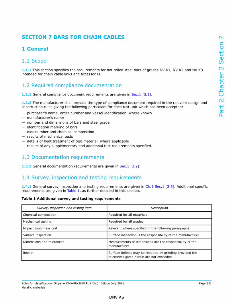
SECTION 7 BARS FOR CHAIN CABLES
1 General
1.1 Scope
1.1.1 This section specifies the requirements for hot rolled steel bars of grades NV K1, NV K2 and NV K3intended for chain cable links and accessories.
1.2 Required compliance documentation
1.2.1 General compliance document requirements are given in Sec.1 [3.1].
1.2.2 The manufacturer shall provide the type of compliance document required in the relevant design andconstruction rules giving the following particulars for each test unit which has been accepted:
— purchaser's name, order number and vessel identification, where known— manufacturer's name— number and dimensions of bars and steel grade— identification marking of bars— cast number and chemical composition— results of mechanical tests— details of heat treatment of test material, where applicable— results of any supplementary and additional test requirements specified.
1.3 Documentation requirements
1.3.1 General documentation requirements are given in Sec.1 [3.2].
1.4 Survey, inspection and testing requirements
1.4.1 General survey, inspection and testing requirements are given in Ch.1 Sec.1 [3.3]. Additional specificrequirements are given in Table 1, as further detailed in this section.
Table 1 Additional survey and testing requirements
Survey, inspection and testing item Description
Chemical composition Required for all materials
Mechanical testing Required for all grades
Impact toughness test Relevant where specified in the following paragraphs
Surface inspection Surface inspection is the responsibility of the manufacturer
Dimensions and tolerances Measurements of dimensions are the responsibility of themanufacturer
Repair Surface defects may be repaired by grinding provided thetolerances given herein are not exceeded
Part 2 Chapter 2 Section 7
Rules for classification: Ships — DNV-RU-SHIP Pt.2 Ch.2. Edition July 2021 Page 151Metallic materials
DNV AS

1.5 Manufacture
1.5.1 All bars shall be made at works approved by the Society.
1.6 Condition of supply
1.6.1 Unless otherwise approved, the bars shall be delivered in the as rolled condition.
2 Testing
2.1 Chemical composition
2.1.1 The chemical composition of each cast shall be determined and comply with the overall limits given inTable 2 and, where applicable, the approved specification.
2.2 Test units, test material and number of tests
2.2.1 Bars of the same nominal diameter shall be presented in test units of 50 tonnes or fraction thereoffrom the same cast.
2.2.2 Test material shall consist of a suitable length from one bar in each test unit. Where chain cables aresupplied in the as-rolled condition, see [1.6.1], the test material shall be simulated heat-treated in full cross-section, using the heat treatment parameters recommended by the chain cable manufacturer. Test materialshall be suitably marked for identification with the bars represented.
2.2.3 For each test unit, one tensile and, where required, three Charpy V-notch test specimens shall betaken in the longitudinal direction at a depth one third radius below the surface. For Charpy testing, thenotch shall be cut in a face of the test specimen which was originally approximately perpendicular to therolled surface.
2.2.4 The preparation of test specimens and the procedures used for mechanical testing shall comply withthe relevant requirements of Ch.1.
2.3 Mechanical properties
2.3.1 For mechanical testing, bar material shall be tested in the condition of heat treatment used for thechain as advised by the chain manufacturer. The mechanical properties shall comply with the values given inTable 2.
2.3.2 If the results do not meet the specified requirements the re-test procedures in Ch.1 Sec.2 [3.8] maybe adopted. Where bars and the associated test material are submitted to re-heat treatment, all the testspreviously performed shall be repeated and the results shall meet the specified requirements.
Part 2 Chapter 2 Section 7
Rules for classification: Ships — DNV-RU-SHIP Pt.2 Ch.2. Edition July 2021 Page 152Metallic materials
DNV AS

Table 2 Material requirements for bars for chain cables
Grade NV K1 NV K2 NV K3
Deoxidation and fine-grain treatment Killed Killed, fine-graintreated with Al
Killed, fine-grain treated
Heat treatment for finished chain cables As welded ornormalised
As welded ornormalised
Quenched andtempered,normalised,or normalisedand tempered
C (%) 0.20 0.24 0.33
Mn (%) 0.40 to 1.60 0.50 to 1.60 0.60 to 1.90
Si (%) 0.15 to 0.35 0.15 to 0.55 0.15 to 0.55
P (%) 0.040 0.035 0.035
S (%) 0.040 0.035 0.035
Al (%) - 0.020 to 0.065 0.020 to 0.065 3)
Chemicalcomposition 1)
N (%) - - 0.015
Yield strength ReH or proofstress Rp0.2 (N/mm
2) - Min. 295 Min. 410
Tensile strength Rm (N/mm2) 370 to 490 490 to 690 Min. 690
Elongation A5 min. (%) Min. 25 Min. 22 Min. 17
Reduction of area Z min. (%) - - Min. 40
Minimumaverageenergy (J)
- 27 2) 60
Mechanicalproperties
Charpy V-notchTest
temperature(°C)
- 0 0
1) Given value is maximum content (by weight) unless shown as a range or as a minimum.2) Impact tests may be waived when the chain cable shall be supplied normalised.3) One or more of the elements Al, Nb or V shall be present in sufficient amount.
Part 2 Chapter 2 Section 7
Rules for classification: Ships — DNV-RU-SHIP Pt.2 Ch.2. Edition July 2021 Page 153Metallic materials
DNV AS

3 Inspection, tolerances and repair
3.1 Inspection and tolerances
3.1.1 Surface inspection and verification of dimensions are the responsibility of the manufacturer.
3.1.2 The diameter and roundness shall be within the tolerances given in Table 3.
Table 3 Dimensional tolerance of rolled bars
Nominal diameter [mm] Tolerance on diameter [mm]) Tolerance on roundness (dmax – dmin) (mm)
< 25 -0 / +1.0 0.6
25 to 35 -0 / +1.2 0.8
36 to 50 -0 / +1.6 1.1
51 to 80 -0 / +2.0 1.5
81 to 100 -0 / +2.6 1.95
101 to 120 -0 / +3.0 2.25
121 to 160 -0 / +4.0 3.00
3.2 Repair
3.2.1 Surface defects may be repaired by grinding provided the admissible tolerance is not exceeded.
4 Identification
4.1 Marking
4.1.1 The minimum markings required for the bars are:
— the manufacturer's brand mark— the steel grade— an abbreviated symbol of the cast.
Bars having diameter of up to and including 40 mm combined into bundles, may be marked on permanentlyaffixed labels.
Part 2 Chapter 2 Section 7
Rules for classification: Ships — DNV-RU-SHIP Pt.2 Ch.2. Edition July 2021 Page 154Metallic materials
DNV AS
SECTION 8 STEEL CASTINGS
1 General requirements
1.1 Scope
1.1.1 Requirements for steel castings intended for use in the construction of hulls, equipment, machinery,boilers, pressure vessels and piping systems are specified.
1.1.2 Where required by the relevant parts of the rules, steel castings shall comply with the requirements ofCh.1, of Sec.1, the general requirements of [1] and the appropriate specific requirements of [2] to [7]. If thespecific requirements differ from the general requirements, the specific requirements shall prevail.
1.1.3 As an alternative to [1.1.2], materials which comply with national or proprietary specifications may beaccepted provided such specifications give reasonable equivalence to the requirements of this section or areapproved for each specific application, see Ch.1 Sec.1 [3.4]. As a minimum the following particulars shall bespecified:
— manufacturing process— chemical composition— heat treatment— mechanical properties— non-destructive testing.
For machinery components, see also Pt.4.
1.2 Required compliance documentation
1.2.1 General compliance document requirements are given in Sec.1 [3.1]. Additional certificationrequirements for materials covered by this section are given in [1.2.2] and [1.2.3].
1.2.2 The manufacturer shall provide the type of compliance document required in the relevant rules givingthe following particulars for each test unit of castings which has been accepted:
— purchaser’s name, order number and vessel identification, where known— manufacturer’s name— description of castings, cast steel grade and steel quality— identification marking of castings— steel making process, cast number and chemical composition of each heat— details of heat treatment, including temperatures and holding time at temperature, heat number— results of mechanical tests— results of non-destructive tests and details of test procedure, where applicable— test pressure, where applicable— results of any supplementary and additional test requirements specified.
1.2.3 For propeller castings, the following additional information shall be given:
— drawing number— diameter, number of blades, pitch, direction of turning— skew angle for high skew propellers— final weight— records of weld repairs.
Part 2 Chapter 2 Section 8
Rules for classification: Ships — DNV-RU-SHIP Pt.2 Ch.2. Edition July 2021 Page 155Metallic materials
DNV AS

1.3 Documentation requirements
1.3.1 General documentation requirements are given in Sec.1 [3.2]. Additional product specificdocumentation requirements are given in Table 1, and additional manufacturer specific documentationrequirements are given in Table 2.
Table 1 Documentation requirements – products required to be certified
Object Documentation type Additional description Info
Steel material M010 – Material specification, metals Castings for crankshafts and connecting rods FΙ
Table 2 Qualification documentation manufacturer
Item Documentation type Additional description
Castings NV or W certificate or TR — the content of grain refining elements shall bereported
— elements designated as residual elements in theindividual specifications shall be reported.
Castings subject to flame-scarfing or arc-air gouging
Carbon equivalent documentation Steel casting with carbon equivalent Ceq ≥ 0.40shall be preheated before flame-scarfing or arc-airgouging.
Castings subject to majorrepair by welding
Z250 - Procedure Proposals for major weld repairs shall beaccompanied a tailor-made procedure includingsketches or photographs showing the extent andpositions of the repairs. Special attention should bepaid to the high stress areas. A grain refining heattreatment shall be given to the whole casting priorto major repairs, unless otherwise approved. Theprocedure shall be approved case by case.
Castings subject to minorrepair by welding andwhere local stress relivingis intended
Z250 - Procedure Proposal and procedure for local stress relieving heattreatment. Subject to prior approval, local stressrelieving heat treatment may be accepted for minorrepairs. The proposal shall justify the need for localstress relieving rather than full stress relieving.
Castings subject to minorrepair by welding andwhere omission of stressrelieving is intended
Z250 - Procedure Proposal for omission of stress relieving heattreatment. Special consideration may be given tothe omission of stress relieving heat treatmentfor minor repairs in areas of low operating stressand provided that the combination of material andwelding procedure is such that tensile residualstresses and hardness are minimised:
— documentation of low operating stress— documentation showing that the combination of
material and welding procedure gives minimizedresidual stress and hardness.
1.3.2 For general requirements to documentation including definitions, see DNV-CG-0550.
Part 2 Chapter 2 Section 8
Rules for classification: Ships — DNV-RU-SHIP Pt.2 Ch.2. Edition July 2021 Page 156Metallic materials
DNV AS

1.4 Survey, inspection and testing requirements
1.4.1 General survey, inspection and testing requirements are given in Ch.1 Sec.1 [3.3]. Additional specificrequirements are given in Table 3, as further detailed in this section.
Table 3 Additional survey and testing requirements
Survey, inspection and testing item Description
Chemical composition Required for all materials.
Mechanical testing Required for all grades in accordance with the requirements of therelevant section.
Impact toughness test Relevant for all grades where specified in the following sections.
Impact toughness test of austenitic steel castings Charpy V-notch impact testing may be omitted if the designtemperature is above –105°C.
Test unit for large castings For castings with mass 10 tonnes or more, two sets of mechanicaltests are required for each test unit. The test blocks shall belocated as widely separated as possible.
Test unit for castings made from two or more casts Where large castings are made from two or more casts, whichare not mixed in a ladle prior to pouring, two or more sets ofmechanical tests are required corresponding to the numberof casts involved. The test blocks shall be located as widelyseparated as possible.
Visual inspection The manufacturer shall carry out visual inspection of all castingon accessible surfaces for surface finish and compliance with thedimensional and geometrical tolerances.
Visual survey Castings for which certification by the Society is required shall bepresented to the surveyor for visual inspection. The surveyor mayrequire areas to be etched for the purpose of investigating weldrepairs.
Dimensional measurements The dimensions and tolerances are governed by the datacontained in the approval drawings or order documents. Theseshall be submitted to the surveyor at the time of the test. Unlessotherwise agreed between the purchaser and the manufacturer,the verification of dimensions is the responsibility of themanufacturer.
Part 2 Chapter 2 Section 8
Rules for classification: Ships — DNV-RU-SHIP Pt.2 Ch.2. Edition July 2021 Page 157Metallic materials
DNV AS

Survey, inspection and testing item Description
NDT — castings shall be subject to non-destructive testingas specified in [2] to [7] and shall comply with givenrequirements. In addition, the relevant construction rules shallbe referred for non-destructive testing of finished machinedcomponents
— where MT or PT is specified, the tests shall be carried outafter the final heat treatment when the surface is in the finalcondition, but before any cold working. Machined castingsshall be tested after final machining. PT may only be appliedwhere MT is not possible or suitable and for interpretation ofopen indications detected by MT
— where UT is specified, the tests shall be carried out afterthe final heat treatment when the casting surface has beenbrought to a condition suitable for UT
— where certification by the Society is required, the surveyormay request to be present during NDT
NDT of repairs — complete elimination of the defective material shall beverified by MT or PT. This applies also for areas which will besubsequently repaired by welding
— all repaired areas shall be subject to NDT as specified in[1.12]
NDT of propellers: PT For all propellers, separately cast blades and hubs, the surfacescovered by severity zones A, B and C are subject to PT. Testing ofzone A shall be undertaken in the presence of the surveyor whilsttesting of zones B and C may be witnessed by the surveyor uponhis request.
NDT of Propellers: RT, UT The Society may require NDT such as RT or UT for verification ofinternal soundness. The extent, method and acceptance criteriashall be agreed between the manufacturer and the Society.
Pressure test Pressure retaining castings shall be tested after machining to thetest pressure required by the relevant design and constructionparts of the rules.
1.5 Grading system
1.5.1 The castings concerned are classified by chemical composition into three steel types:
— carbon and carbon-manganese (C and C-Mn) steel— alloy steel— stainless steel.
1.5.2 Where applicable, C and C-Mn steels and alloy steels are in general covered by several gradesdesignated by their specified minimum tensile strength. Ferritic alloy steels and stainless steels aredesignated by chemical composition.
Guidance note:For the purpose of this grading system, C and C-Mn steels are classified as one type and considered to be those steels in whichcarbon and manganese are the principal alloying elements.
---e-n-d---o-f---g-u-i-d-a-n-c-e---n-o-t-e---
Part 2 Chapter 2 Section 8
Rules for classification: Ships — DNV-RU-SHIP Pt.2 Ch.2. Edition July 2021 Page 158Metallic materials
DNV AS

1.5.3 Special grade castings are defined based on specific requirements for sampling practice, see [1.9.4].These grades shall be appended with an "S" in the grade name,
Note:For the special grade steel castings specific requirements for the test block do apply, see [1.9], whereas there are no differenceswith respect to chemical composition, heat treatment and mechanical properties.
---e-n-d---o-f---n-o-t-e---
Guidance note:Due to a test block size more representative of the actual product size for the special grade steel castings, the mechanicalproperties obtained by testing are expected to be more representative of the final product. The special grade may typically bespecified by the referring rules or standard, or requested by the purchaser.
---e-n-d---o-f---g-u-i-d-a-n-c-e---n-o-t-e---
1.6 Manufacture
1.6.1 All castings delivered with NV or works certificate shall be made at foundries approved by the Society,see Ch.1 Sec.2 [2.2.2].
1.6.2 Steel shall be manufactured by an electric or one of the basic oxygen processes or any other processinvolving secondary refining. All castings shall be made from killed steel unless otherwise approved.
1.6.3 All flame cutting, scarfing or arc-air gouging to remove surplus metal shall be undertaken inaccordance with recognized good practice and, unless otherwise agreed, be carried out before the final heattreatment. Preheating shall be employed when necessitated by the chemical composition or thickness of thecastings. The affected areas shall be either machined or ground smooth.
1.6.4 Where two or more castings are joined by welding to form a composite item, the welding workshopshall be qualified accordingly, see Ch.1 Sec.2 [2.1]. The welding procedure shall be qualified and the weldingprocedure specification (WPS) shall be approved. Welding procedure qualification testing (WPQT) shall followthe requirements of Ch.4 Sec.5 unless otherwise approved.The WPS shall comply with the corresponding requirements of the approved drawing.
1.7 Chemical composition
1.7.1 The chemical composition of each cast shall be determined by the manufacturer, and shall be withinthe specified limits. The sample for chemical composition shall preferably be taken during the pouring.
1) Where one cast is tapped into one or more ladles before pouring into the moulds, the cast analysis shallbe determined.
2) Where multiple casts are tapped and mixed in a ladle before pouring into the mould, the ladle analysisshall be determined.
3) Where multiple casts are poured into one mould, without first being mixed in one ladle, the chemicalcomposition of each cast (a) or each ladle (b) shall be determined preferably during pouring.
1.7.2 Unless otherwise specified, suitable grain refining elements may be used at the discretion of themanufacturer. The content of such elements shall be reported.
1.7.3 Elements designated as residual elements in the individual specifications shall be reported. Suchelements shall not be intentionally added to the steel.
Part 2 Chapter 2 Section 8
Rules for classification: Ships — DNV-RU-SHIP Pt.2 Ch.2. Edition July 2021 Page 159Metallic materials
DNV AS

1.8 Heat treatment
1.8.1 All castings shall be heat-treated as specified in [2] to [7].
1.8.2 In the case of very large castings alternative methods for heat treatment will be specially considered.
1.8.3 Sufficient thermocouples shall be connected to the furnace charge (minimum at lower part and thickestpart of charge) to measure and record that its temperature is adequately uniform. This requirement does notapply when the temperature uniformity of the furnace is verified according to a recognized standard (e.g.ASTM A991) at regular intervals as agreed with the Society.
1.8.4 The foundry shall maintain records of heat treatment identifying the furnace used, furnace charge,date, temperature and time at temperature. The records shall be presented to the surveyor on request.
1.8.5 If a casting is locally reheated or any straightening operation is performed after the finishing heattreatment, a subsequent stress relieving heat treatment is required unless otherwise approved.
Guidance note:Holding time at normalizing, quenching and tempering temperature is typically one hour per 25.5 mm of the heaviest thickness ofthe casting, for castings with a thickness up to 127.5 mm. For castings with thickness more than 127.5 mm, at least one hour (orcorresponding part thereof) is added for each addition of 102 mm.
---e-n-d---o-f---g-u-i-d-a-n-c-e---n-o-t-e---
1.9 Test blocks and test specimens for mechanical testing
1.9.1 Test blocks, from which test specimens are taken, shall be cast integrally with the casting. When thisis impracticable, the test blocks shall be cast with and gated to the casting. In either case these test blocksshall not be detached from the casting until the heat treatment has been completed.If the test block has to be removed from the casting before final heat treatment, e.g. for the purposeof machining, the surveyors shall be invited for witnessing of the process of test block removal beforemachining and re-attaching to the casting after machining but before final heat treatment.
1.9.2 In the case of small castings of about same size and less than 1000 kg in finished mass, the testblocks may alternatively be cast separately provided they are cast from the same cast of steel as theproduction castings represented and heat-treated with the castings. Separately cast test blocks shall receivesubstantially the same casting practices as the castings represented.
1.9.3 All test blocks shall be suitably marked to identify them with the castings represented.
1.9.4 The requirements for test block dimensions are given for general grade castings and for special gradecastings. Unless otherwise specified, e.g. in the referring standard, the requirements for general gradecastings apply, see [1.5.3]. The dimensions of test blocks (integrally cast and separately cast) shall:
— For general grade castings: shall be in accordance with recognised standards, but shall in all cases have aminimum thickness of 30 mm. The test specimens shall be taken with their axis at least 14 mm from thecast surface. If the thickness of the test block is greater than 56 mm, the axis of the test specimen shallbe at least one quarter thickness from the cast surface.
— For special grade castings: be representative of the dimensions of the represented casting. Preferablya sacrificial casting of same cast and size, and following same heat treatment as the production castingrepresented. Alternatively, a cylindrical solid or rectangular cuboid test block following the requirements of[1.9.1] may be prepared for testing. It shall have the following dimensions: Diameter/thickness shall besame or more than the critical cross section thickness (CCST) and length shall be at least 3 times CCST.
Part 2 Chapter 2 Section 8
Rules for classification: Ships — DNV-RU-SHIP Pt.2 Ch.2. Edition July 2021 Page 160Metallic materials
DNV AS
The longitudinal axis of the test specimens shall be at least 1/2 r (radius) or 1/4 t (thickness) below anyheat treated surface, and at least at distance of CCST below the other heat treated surfaces.
Guidance note:The controlling section thickness (CCST) is the diameter of the largest theoretical sphere which can be inscribed within thecasting.
---e-n-d---o-f---g-u-i-d-a-n-c-e---n-o-t-e---
1.9.5 For castings where the method of manufacture has been case by case approved by the Society, thenumber and position of test samples shall be agreed with the Society.
1.9.6 The size, thickness location and preparation of test specimens and the procedures used for mechanicaltesting shall comply with the relevant requirements of Ch.1.
1.10 Test units and number of tests
1.10.1 For castings with finished mass 1000 kg or more, each casting shall be regarded as the test unit.
1.10.2 For small castings of about same size, where each casting is less than 1000 kg in mass, batch testingis permitted and each cast in each heat treatment charge shall be regarded as the test unit.
1.10.3 At least one set of mechanical tests is required for each test unit, except as specified in [1.10.4] and[1.10.5].
1.10.4 For castings with mass 10 tonnes or more, two sets of mechanical tests are required for each testunit. The test blocks shall be located as widely separated as possible.
1.10.5 Where large castings are made from two or more casts, which are not mixed in a ladle prior topouring, two or more sets of mechanical tests are required corresponding to the number of casts involved.The test blocks shall be located as widely separated as possible.
1.10.6 Additional requirements for propeller castings are given in [4].
1.11 Mechanical properties
1.11.1 The mechanical properties specified in [2] to [7] refer to test specimens machined from integrallycast or separately cast test blocks and not to the castings themselves.
1.11.2 If the results do not meet the specified requirements, the re-test procedures of Ch.1 Sec.2 [3.8] maybe adopted. Where the castings and test blocks are submitted to re-heat treatment, they may not be solutiontreated or re-austenitized more than twice. All the tests previously performed shall be repeated after re-heattreatment and the results shall meet the specified requirements.
1.12 Inspection
1.12.1 All castings shall be visually inspected by the manufacturer on accessible surfaces for surfacefinish, verification of dimensions and compliance with the dimensional and geometrical tolerances. Whereapplicable, this shall include the inspection of internal surfaces and bores. The surfaces shall be adequatelyprepared for inspection. Suitable methods include pickling, caustic cleaning, wire brushing, local grinding,shot or sand blasting. The surfaces shall not be hammered, peened or treated in any way which may obscurediscontinuities.
Part 2 Chapter 2 Section 8
Rules for classification: Ships — DNV-RU-SHIP Pt.2 Ch.2. Edition July 2021 Page 161Metallic materials
DNV AS

1.12.2 Castings for which certification by the Society is required shall be presented to the surveyor for visualinspection. The surveyor may require areas to be etched for the purpose of investigating weld repairs.
1.12.3 When visually inspected, castings shall have a workmanlike finish and be free from adhering sand,scale, cracks, hot tears or other imperfections which, due to their nature, degree or extent, will interfere withthe use of the castings.
1.12.4 Castings shall be subject to non-destructive testing as specified in [2] to [7] and shall fulfil thefollowing requirements:
1) Personnel: all tests shall be carried out by personnel qualified and certified in accordance with recognisedstandards or schemes, e.g. ISO 9712 or ASNT Central Certification Program (ACCP). SNT-TC-1A may beaccepted if the NDT company`s written practice is reviewed and accepted by the Society.
2) Methods: non-destructive testing shall be performed in accordance with the general practice ofrecognised standards, e.g.:
a) magnetic particle testing (MT): ASTM E709, EN 1369, ISO 17638 (for welds), using wet continuousmethod
b) liquid penetrant testing (PT): ISO 3452-1, ASTM E165, EN 1371-1/2c) ultrasonic testing (UT): ASTM A609, ISO 4992-1/2, ISO 17640 (for welds)d) radiographic testing (RT): ISO 4993, ISO 5579 Class B, ASTM E94e) as an alternative to the methods described in 2), methods complying with national or proprietary
standards or specifications may be agreed with the Society provided such standards or specificationsgive reasonable equivalence to the requirements of the listed standards or are especially approved.
3) Extent and acceptance criteria: the extent of non-destructive testing and the acceptance criteria shall beagreed with the Society
a) for MT, PT and UT of hull castings, IACS Rec. No.69 is regarded as an example of an acceptablestandard
b) for RT, ASME 16.34 Appendix I is regarded as an example of an acceptable standardc) as an alternative to a) and b), acceptance criteria comply with national or proprietary standards
or specifications may be agreed with the Society provided such standards or specifications givereasonable equivalence to the requirements of a) or b) or are especially approved.
In addition to this, the construction rules shall be referred for further non-destructive testing requirements.Guidance note:Prior to acceptance of the casting by the Society, the ordering information between purchaser and manufacturer regarding NDTshould preferably be available for the surveyor. The ordering specification with respect to NDT may typically give reference torecognised standards, and/or specify:
— methods, areas, volume and extent of examination
— documentation requirements
— additional requirements as applicable.
---e-n-d---o-f---g-u-i-d-a-n-c-e---n-o-t-e---
1.12.5 The following definitions relevant to MT or PT indications apply, see Figure 1.Part 2 Chapter 2 Section 8
Rules for classification: Ships — DNV-RU-SHIP Pt.2 Ch.2. Edition July 2021 Page 162Metallic materials
DNV AS
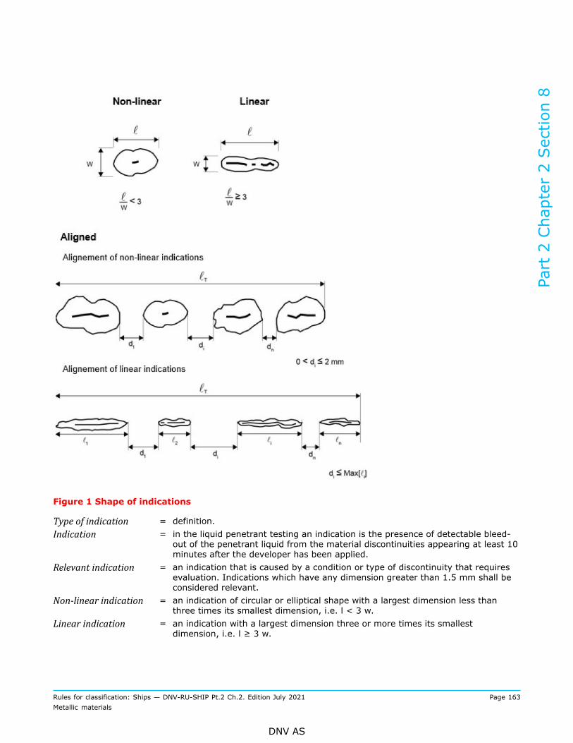
Figure 1 Shape of indications
Type of indication = definition.Indication = in the liquid penetrant testing an indication is the presence of detectable bleed-
out of the penetrant liquid from the material discontinuities appearing at least 10minutes after the developer has been applied.
Relevant indication = an indication that is caused by a condition or type of discontinuity that requiresevaluation. Indications which have any dimension greater than 1.5 mm shall beconsidered relevant.
Non‐linear indication = an indication of circular or elliptical shape with a largest dimension less thanthree times its smallest dimension, i.e. l < 3 w.
Linear indication = an indication with a largest dimension three or more times its smallestdimension, i.e. l ≥ 3 w.
Part 2 Chapter 2 Section 8
Rules for classification: Ships — DNV-RU-SHIP Pt.2 Ch.2. Edition July 2021 Page 163Metallic materials
DNV AS

Aligned indication: = a) non-linear indications form an alignment when the distance betweenindications is less than 2 mm and at least three indications are aligned. Analignment of indications is considered to be a unique indication and its length isequal to the overall length of the alignmentb) linear indications form an alignment when the distance between twoindications is smaller than the length of the longest indication.
1.12.6 Where MT or PT is specified, the tests shall be carried out after the final heat treatment when thesurface is in the final condition, but before any cold working. Machined castings shall be tested after finalmachining. PT may only be applied where MT is not possible or suitable and for interpretation of openindications detected by MT. Where certification by the Society is required, the surveyor may request to bepresent during NDT.
Guidance note:Where a casting is delivered in the as-cast or rough condition for subsequent processing and final MT or PT by the purchaser, therewill always be a risk of subsurface defects appearing on the surface after final machining. The manufacturer should consider thisrisk and perform suitable intermediate inspections taking into consideration the quality level required in finished condition. Theresponsibility of the internal quality of the material lies with the manufacturer.
---e-n-d---o-f---g-u-i-d-a-n-c-e---n-o-t-e---
1.12.7 The castings are subject to MT or PT in the following areas:
— at fabrication weld preparations and over a band width of 30 mm from welding edges— at positions where repair welds are made— at all accessible fillets and abrupt changes of section— at positions where surplus metal has been removed by flame cutting, scarfing or arc-air gouging.
1.12.8 Where UT is specified, the tests shall be carried out after the final heat treatment when the castingsurface has been brought to a condition suitable for UT. RT may also be accepted and applies to castings withthickness less than 50 mm.
1.12.9 The castings are subject to UT or RT in the following areas:
— in way of fabrication weld preparations for a distance of 50 mm from the edge— at positions where major repair welds are made— at any repair welds where the original defect was detected by UT or RT— at all areas to be subsequently machined, e.g. bores of stern boss castings— at positions where gates and feeders have been removed.
1.12.10 The foundry shall maintain records of own inspections including dimensional measurementstraceable to each casting. The records shall be presented to the surveyor on request. The foundry is alsoto provide the surveyor with a statement confirming that non-destructive tests have been carried out withsatisfactory results including information on the test standard and the extent of testing.
1.13 Repair
1.13.1 This paragraph gives general requirements for repair of steel castings. Additional requirements forrepair of propeller castings are given in [4.7]. Higher requirements may be given for certain castings.
1.13.2 Defects may be removed by grinding or by chipping and grinding to a depth of 10% of the sectionthickness or 15 mm, whichever is smaller, provided the remaining thickness is within the given tolerances(including minimum thickness). The resulting grooves shall have a bottom radius of approximately threetimes the groove depth and shall be blended into the surrounding surface so as to avoid any sharp contours.
Part 2 Chapter 2 Section 8
Rules for classification: Ships — DNV-RU-SHIP Pt.2 Ch.2. Edition July 2021 Page 164Metallic materials
DNV AS

Flame-scarfing or arc-air gouging may also be used provided that the surfaces of the resulting grooves aresubsequently ground smooth.Complete elimination of the defective material shall be verified by MT or PT.
Guidance note:Surface hardening and surface carburizing caused by flame-scarfing or air-arc gouging will typically be removed if it is followed bygrinding to a depth of 1 mm or more.
---e-n-d---o-f---g-u-i-d-a-n-c-e---n-o-t-e---
1.13.3 Where the repair entails removal of more than 10% of the thickness or 15 mm, whichever is smaller,the defective area shall be repaired by welding. Shallow defective areas, see [1.13.2], may also be repairedby welding. The excavations shall be suitably shaped to allow good access for welding. The resulting groovesshall be subsequently ground smooth and complete elimination of the defective material shall be verified byMT or PT before and after welding.
1.13.4 Weld repairs are classified as major or minor. A weld repair is considered major when one of thefollowing occurs:
— the depth of the groove prepared for welding exceeds 25% of the section thickness or 25 mm, whicheveris smaller
— or the area of the groove based on length times width exceeds 0.125 m2
— or castings have leaked on hydrostatic testing.
All other weld repairs are considered minor.
1.13.5 Major weld repairs require the case by case approval of the Society before the repair is commenced.Special attention should be paid to the high stress areas. A tailor-made procedure for each major weld repairshall be prepared including accompanied by sketches or photographs showing the extent and positions ofthe repairs. A grain refining heat treatment shall be given to the whole casting prior to major repairs, unlessotherwise approved.Minor weld repairs do not require the approval of the Society before the repair is commenced but shall berecorded on sketches showing the extent and positions of the repairs. The records shall be presented to thesurveyor on request.Cosmetic repair by welding is considered minor weld repairs (unless it is major, as defined in [1.13.4]) andshall follow all the requirements for minor weld repairs.
1.13.6 All weld repairs (both minor and major welding repairs) shall be done by qualified welders usingapproved procedures, see Ch.4.
Guidance note:Alloy steel castings and crankshafts castings should be suitably pre-heated prior to welding. Castings of carbon or carbon-manganese steels may also need preheating depending on chemical composition, dimensions and position of the weld repairs.
---e-n-d---o-f---g-u-i-d-a-n-c-e---n-o-t-e---
1.13.7 The welding consumables used shall be of a suitable composition giving a weld deposit withmechanical properties at least similar to those of the parent castings. Only approved low hydrogenconsumables shall be used. Welding consumables shall be stored and handled so as to maintain the hydrogenclassification and in accordance with the manufacturer’s recommendations.
1.13.8 When repair welding is done after the casting has been heat-treated for mechanical properties, therepaired casting shall be given a furnace stress relieving heat treatment. Unless otherwise agreed, stressrelieving heat treatment shall be carried out at a temperature in the range of 550°C to 620°C, except forquenched and tempered steels. Quenched and tempered steels shall be stress relieved at a temperature atleast 30°C lower than the final tempering temperature, but not below 550°C. The type of heat treatmentemployed will be dependent on the chemical composition of the casting and the dimensions, positions andnature of the repairs. Subject to prior approval, local stress relieving heat treatment may be accepted for
Part 2 Chapter 2 Section 8
Rules for classification: Ships — DNV-RU-SHIP Pt.2 Ch.2. Edition July 2021 Page 165Metallic materials
DNV AS
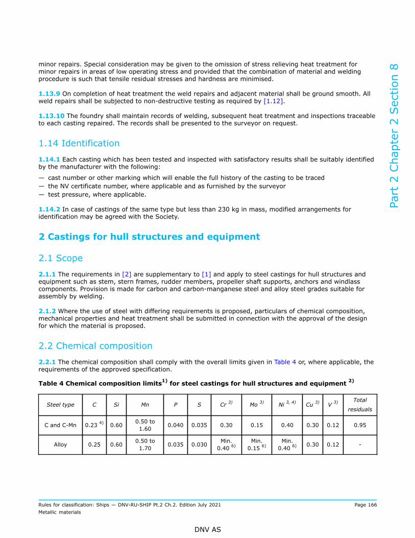
minor repairs. Special consideration may be given to the omission of stress relieving heat treatment forminor repairs in areas of low operating stress and provided that the combination of material and weldingprocedure is such that tensile residual stresses and hardness are minimised.
1.13.9 On completion of heat treatment the weld repairs and adjacent material shall be ground smooth. Allweld repairs shall be subjected to non-destructive testing as required by [1.12].
1.13.10 The foundry shall maintain records of welding, subsequent heat treatment and inspections traceableto each casting repaired. The records shall be presented to the surveyor on request.
1.14 Identification
1.14.1 Each casting which has been tested and inspected with satisfactory results shall be suitably identifiedby the manufacturer with the following:
— cast number or other marking which will enable the full history of the casting to be traced— the NV certificate number, where applicable and as furnished by the surveyor— test pressure, where applicable.
1.14.2 In case of castings of the same type but less than 230 kg in mass, modified arrangements foridentification may be agreed with the Society.
2 Castings for hull structures and equipment
2.1 Scope
2.1.1 The requirements in [2] are supplementary to [1] and apply to steel castings for hull structures andequipment such as stem, stern frames, rudder members, propeller shaft supports, anchors and windlasscomponents. Provision is made for carbon and carbon-manganese steel and alloy steel grades suitable forassembly by welding.
2.1.2 Where the use of steel with differing requirements is proposed, particulars of chemical composition,mechanical properties and heat treatment shall be submitted in connection with the approval of the designfor which the material is proposed.
2.2 Chemical composition
2.2.1 The chemical composition shall comply with the overall limits given in Table 4 or, where applicable, therequirements of the approved specification.
Table 4 Chemical composition limits1) for steel castings for hull structures and equipment 2)
Steel type C Si Mn P S Cr 3) Mo 3) Ni 3, 4) Cu 3) V 3)Total
residuals
C and C-Mn 0.23 4) 0.60 0.50 to1.60 0.040 0.035 0.30 0.15 0.40 0.30 0.12 0.95
Alloy 0.25 0.60 0.50 to1.70 0.035 0.030 Min.
0.40 6)Min.0.15 6)
Min.0.40 6) 0.30 0.12 -
Part 2 Chapter 2 Section 8
Rules for classification: Ships — DNV-RU-SHIP Pt.2 Ch.2. Edition July 2021 Page 166Metallic materials
DNV AS

Steel type C Si Mn P S Cr 3) Mo 3) Ni 3, 4) Cu 3) V 3)Total
residuals
1) Given value is maximum content ([%] by weight) unless shown as a range or as a minimum.2) Castings not intended for welding may be supplied to the composition limits given in Table 6. Steel castings for
anchors shall be fine grain treated with aluminium.3) Elements are considered as residual elements unless shown as a range or as a minimum.4) For class notation DAT, see Table 5.5) An increase is permitted up to maximum 0.30% provided that the manganese content is reduced to maximum
1.20%.6) One or more of the elements shall comply with the minimum content.
2.3 Heat treatment
2.3.1 Carbon and carbon-manganese steel castings shall be supplied in one of the following conditions:
— normalised— normalised and tempered at a temperature of not less than 550°C— quenched and tempered at a temperature of not less than 550°C.
2.3.2 Alloy steel castings shall be quenched and tempered at a temperature of not less than 550°C.Alternatively, they may be supplied in the normalised and tempered condition, in which case the specifiedmechanical properties shall be agreed with the Society.
2.4 Mechanical properties
2.4.1 The mechanical properties shall comply with the values given in Table 5 or, where applicable, therequirements of the approved specification.
2.4.2 Where it is proposed to use a steel with a specified minimum tensile strength intermediate to thosegiven in Table 5, corresponding minimum values for the other properties may be obtained by interpolation(relative to the specified minimum tensile strength).
Table 5 Mechanical properties for steel castings for hull structures and equipment
Charpy V-notchimpact toughness
Steel type Steelgrade
Yield strengthRp0.2 minimum[N/mm2]
Tensile strengthRm minimum[(N/mm2]
Elongation A5minimum [%]
Reductionof area Z
minimum [%]Test
temperature[°C] 1)
Minimumaverageenergy [J]
NVC400UW 200 400 25 40 0 27
NVC440UW 220 440 22 30 0 27
NVC480UW 240 480 20 27 0 27
C and C-Mn 3)
NVC520UW 260 520 18 25 0 27
Part 2 Chapter 2 Section 8
Rules for classification: Ships — DNV-RU-SHIP Pt.2 Ch.2. Edition July 2021 Page 167Metallic materials
DNV AS
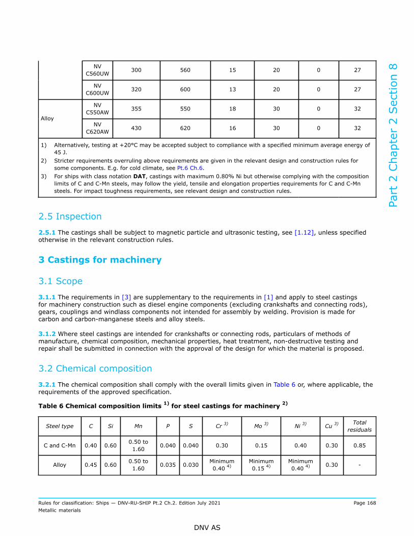
NVC560UW 300 560 15 20 0 27
NVC600UW 320 600 13 20 0 27
NVC550AW 355 550 18 30 0 32
AlloyNV
C620AW 430 620 16 30 0 32
1) Alternatively, testing at +20°C may be accepted subject to compliance with a specified minimum average energy of45 J.
2) Stricter requirements overruling above requirements are given in the relevant design and construction rules forsome components. E.g. for cold climate, see Pt.6 Ch.6.
3) For ships with class notation DAT, castings with maximum 0.80% Ni but otherwise complying with the compositionlimits of C and C-Mn steels, may follow the yield, tensile and elongation properties requirements for C and C-Mnsteels. For impact toughness requirements, see relevant design and construction rules.
2.5 Inspection
2.5.1 The castings shall be subject to magnetic particle and ultrasonic testing, see [1.12], unless specifiedotherwise in the relevant construction rules.
3 Castings for machinery
3.1 Scope
3.1.1 The requirements in [3] are supplementary to the requirements in [1] and apply to steel castingsfor machinery construction such as diesel engine components (excluding crankshafts and connecting rods),gears, couplings and windlass components not intended for assembly by welding. Provision is made forcarbon and carbon-manganese steels and alloy steels.
3.1.2 Where steel castings are intended for crankshafts or connecting rods, particulars of methods ofmanufacture, chemical composition, mechanical properties, heat treatment, non-destructive testing andrepair shall be submitted in connection with the approval of the design for which the material is proposed.
3.2 Chemical composition
3.2.1 The chemical composition shall comply with the overall limits given in Table 6 or, where applicable, therequirements of the approved specification.
Table 6 Chemical composition limits 1) for steel castings for machinery 2)
Steel type C Si Mn P S Cr 3) Mo 3) Ni 3) Cu 3) Totalresiduals
C and C-Mn 0.40 0.60 0.50 to1.60 0.040 0.040 0.30 0.15 0.40 0.30 0.85
Alloy 0.45 0.60 0.50 to1.60 0.035 0.030 Minimum
0.40 4)Minimum0.15 4)
Minimum0.40 4) 0.30 -
Part 2 Chapter 2 Section 8
Rules for classification: Ships — DNV-RU-SHIP Pt.2 Ch.2. Edition July 2021 Page 168Metallic materials
DNV AS

1) Given value is maximum content ([%] by weight) unless shown as a range or as a minimum.2) Castings intended for welding shall comply with the composition limits given in Table 4.3) Elements are considered as residual elements unless shown as a range or as a minimum.4) One or more of the elements shall comply with the minimum content.
3.3 Heat treatment
3.3.1 Carbon and carbon-manganese steel castings shall be supplied in one of the following conditions:
— fully annealed— normalised— normalised and tempered at a temperature of not less than 550°C— quenched and tempered at a temperature of not less than 550°C.
3.3.2 Alloy steel castings shall be quenched and tempered at a temperature of not less than 550°C.Alternatively, they may be supplied in the normalised and tempered condition, in which case the specifiedmechanical properties shall be agreed with the Society.
3.3.3 Castings for components as specified in Pt.4 and any other castings where dimensional stability andfreedom from internal stresses are important, shall be given a stress relief heat treatment. Unless otherwiseapproved, this shall be at a temperature not lower than 550°C, followed by furnace cooling to 300°C orlower. Alternatively, full annealing may be used provided that the castings are furnace cooled to 300°C orlower.
3.4 Mechanical properties
3.4.1 The mechanical properties shall comply with the values given in Table 7 or, where applicable, therequirements of the approved specification.
3.4.2 Where it is proposed to use steel with a specified minimum tensile strength intermediate to thosegiven in Table 7, corresponding minimum values for the other properties may be obtained by interpolation.
Part 2 Chapter 2 Section 8
Rules for classification: Ships — DNV-RU-SHIP Pt.2 Ch.2. Edition July 2021 Page 169Metallic materials
DNV AS

Table 7 Mechanical properties for steel castings for machinery
Charpy V-notch 1, 2)
Steel type Steelgrade
Yield strength
Rp0.2 minimum
[N/mm2]
Tensilestrength, Rmminimum
[N/mm2]
ElongationA5 minimum
[%]
Reductionof area Zminimum
[%]
Testtemperature
[°C]
Minimumaverageenergy
[J]
NV C400U 200 400 25 40 20 25
NV C440U 220 440 22 30 20 20
NV C480U 240 480 20 27 20 18
NV C520U 260 520 18 25 20 15
NV C560U 300 560 15 20 20 12
C and C-Mn
NV C600U 320 600 13 20 20 10
NV C550A 340 550 16 35 20 32
NV C600A 400 600 16 35 20 32Alloy
NV C690A 490 690 13 30 20 32
1) Machinery components intended for polar class vessels; materials exposed to sea water or sea water temperatureshall be tested at -10°C. Materials of essential components exposed to low air temperature shall be tested at 10°Cbelow the lowest design temperature, unless otherwise approved. E.g. see Pt.6 Ch.6. The obtained average energyshall be ≥ 20 J.
2) Stricter requirements overruling above requirements may be given in the relevant design and construction rules forsome components.
3.5 Inspection
3.5.1 The castings are subject to magnetic particle and ultrasonic testing, see [1.12], as specified in therelevant construction rules.
4 Castings for propellers
4.1 Scope
4.1.1 The requirements are supplementary to the requirements in [1] and apply to stainless steel castingsfor propellers, blades, hubs and bosses. These requirements may also be used for the repair of propellersdamaged in service, subject to prior agreement with the Society.
4.2 Manufacture
4.2.1 Casting shall be performed in dry moulds using degassed liquid metal. The casting process shall besupervised in order to prevent eddies occurring. Special devices or procedures shall be in place to ensure thatno slag can enter the mould.
Part 2 Chapter 2 Section 8
Rules for classification: Ships — DNV-RU-SHIP Pt.2 Ch.2. Edition July 2021 Page 170Metallic materials
DNV AS
4.3 Chemical composition
4.3.1 The chemical composition shall comply with the overall limits given in Table 8 or, where applicable, therequirements of the approved specification.The manufacturer shall maintain records of the chemical analyses of the production casts, which shall bemade available to the Society.
4.4 Heat treatment
4.4.1 Martensitic steel castings shall be quenched and tempered. Austenitic steel castings shall be solutionheat-treated.
4.5 Mechanical testing
4.5.1 The mechanical properties shall comply with the overall limits given in Table 9 or, where applicable, therequirements of the approved specification.
4.5.2 Test blocks shall be cast integral with the hub of propeller castings, or with the flange of propellerblade castings, or on the blade. The test bars attached on blades shall be located in an area between 0.5 R to0.6 R, where R is the radius of the propeller. Removal of test blocks shall be by non-thermal procedures.
4.5.3 Separately cast test bars may be used for mechanical testing, subject to prior approval of the Society.The test bars shall be cast from the same heat as the castings represented and heat treated with the castingsrepresented.
4.5.4 One set of tests shall be made on material representing each casting. The mechanical properties shallcomply with the values given in Table 9 or, where applicable, the requirements of the approved specification.
4.5.5 As an alternative to [4.5.2] and [4.5.4], batch testing using separately cast test blocks may beadopted for small propellers of about the same size and less than 1 m diameter. For batch testing, one set oftests shall be made for all cast in:
— each furnace charge and— each multiple of five castings in the batch.
4.6 Inspection
4.6.1 The castings are subject to inspection in accordance with [1.12] and as given in [4.6.3] to [4.6.18].
4.6.2 Visual testing: all finished castings shall be 100% visually inspected by the manufacturer. Castingsshall be free from cracks, hot tears or other imperfections which, due to their nature, degree or extent, willinterfere with the use of the castings. A general visual examination shall be carried out by the Society.
4.6.3 In order to relate the degree of inspection to the criticality of imperfections, propeller blades aredivided into three severity zones designated A, B and C:
— zone A is the region where the operation stresses are high— zone B is a region where the operation stresses may be high— zone C is a region in which the operation stresses are low and where the blade thicknesses are relativelysmall.
Part 2 Chapter 2 Section 8
Rules for classification: Ships — DNV-RU-SHIP Pt.2 Ch.2. Edition July 2021 Page 171Metallic materials
DNV AS

4.6.4 A distinction shall be made between high skew and low skew propellers. High skew propellers have askew angle greater than 25°, low skew propellers have a skew angle of up to 25°. The maximum skew angleof a propeller blade is defined as the angle, in projected view of the blade, between a line drawn through theblade tip and the shaft centerline and a second line through the shaft centerline which acts as a tangent tothe locus of the mid-points of the helical blade section, see Figure 2.
4.6.5 Zone A in low skew propellers is in the area on the pressure side of the blade, from and including thefillet to 0.4 R and bounded on either side by lines at a distance 0.15 times the chord length CR from theleading edge and 0.2 times CR from the trailing edge respectively, see Figure 3. Where the hub radius (RB)exceeds 0.27 R, the other boundary of zone A shall be increased to 1.5 RB. Zone A also includes the parts ofthe separate cast propeller hub that are located in the area of the windows as described in Figure 5 and theflange and fillet area of controllable pitch and built-up propeller blades as described in Figure 6.
4.6.6 Zone B in low skew propellers is on the pressure side the remaining area up to 0.7 R and on thesuction side the area from the fillet to 0.7 R, see Figure 3.
4.6.7 Zone C in low skew propellers is the area outside 0.7 R on both sides of the blade. It also includes thesurface of the hub of a mono-block propeller and all the surfaces of the hub of a controllable pitch propellerother than those designated zone A above.
4.6.8 Zone A in high skew propellers is the area on the pressure face contained within the blade root-filletand a line running from the junction of the leading edge with the root fillet to the trailing edge at 0.9 R andat passing through the mid-point of the blade chord at 0.7 R and a point situated at 0.3 of the chord lengthfrom the leading edge at 0.4 R. It also includes an area along the trailing edge on the suction side of theblade from the root to 0.9 R and with its inner boundary at 0.15 of the chord lengths from the trailing edge.See Figure 4.
4.6.9 Zone B in high skew propellers constitutes the whole of the remaining blade surfaces. See Figure 4.
4.6.10 Bores of bosses of controllable pitch propellers intended for mounting the boss on the propeller shaftshall be classed as zone A. The remaining surface of the blades shall be divided into the zones shown inFigure 3 and Figure 4.
4.6.11 Liquid penetrant testing (PT): for all propellers, separately cast blades and hubs, the surfaces coveredby severity zones A, B and C are subject to PT. Testing of zone A shall be undertaken in the presence of thesurveyor whilst testing of zones B and C may be witnessed by the surveyor upon his request.
4.6.12 For the purpose of evaluating PT indications, the surface shall be divided into reference areas of 100cm2, which may be square or rectangular with the major dimension not exceeding 250 mm. The area shall betaken in the most unfavourable location relative to the indication being evaluated.
4.6.13 The indications detected may, with respect to their size and number, not exceed the values given inTable 10.For areas repaired by grinding, 100% re-inspection by PT is required.For areas repaired by welding and subsequent grinding, independent of the repaired location, 100% PT isrequired and the repaired areas shall always be assessed according to zone A.
4.6.14 The Society may require NDT such as RT or UT for verification of internal soundness. The extent,method and acceptance criteria are then to be agreed between the manufacturer and the Society.
4.6.15 Magnetic particle testing may be used in lieu of liquid penetrant testing for examination of martensiticstainless steel castings. Magnetic particle testing procedure shall be submitted to the Society and shall be inaccordance with ISO 9934-1 or a standard recognized by the Society.
Part 2 Chapter 2 Section 8
Rules for classification: Ships — DNV-RU-SHIP Pt.2 Ch.2. Edition July 2021 Page 172Metallic materials
DNV AS
4.6.16 Radiographic and ultrasonic testing: when required by the Society, or when deemed necessary by themanufacturer, further non-destructive testing (e.g. radiographic and/or ultrasonic testing) shall be carriedout. The acceptance criteria or applied quality levels shall be agreed between the manufacturer and theSociety in accordance with a recognized standard.
Note:Due to the attenuating effect of ultrasound within austenitic steel castings, ultrasonic testing may not be practical in some cases,depending on the shape/type/thickness, and grain-growth direction of the casting.
---e-n-d---o-f---n-o-t-e---
4.6.17 Minor casting defects which are visible after machining such as small sand and slag inclusions, smallcold shuts and scabs shall be trimmed off by the manufacturer, see [4.7].
4.6.18 Casting defects which may be prejudicial to the proper application of the casting in service, e.g.major non-metallic inclusions, shrinkage cavities, blow holes and cracks are not permitted. These maybe removed by one of the methods given in [4.7] and repaired within the limits and restrictions for therespective severity zones.
4.7 Repair
4.7.1 Defective castings shall be repaired in accordance with [1.13] and as given in [4.7.2] to [4.7.13].
4.7.2 The foundry shall record all repairs, subsequent heat treatment and inspections traceable to eachrepaired area for each casting repaired. The records shall be presented to the surveyor on request.
4.7.3 The repairs shall be carried out by mechanical means, e.g. by grinding, chipping or milling. Weldrepairs shall be undertaken only when they are considered to be necessary.
4.7.4 If repairs have been made either by grinding or by welding, the repaired areas shall additionally besubjected to the liquid penetrant testing independent of their location and/or severity zone. Weld repairsshall, independent of their location, always be assessed according to zone A.
4.7.5 Weld repairs require the approval of the Society before the repair is commenced. Proposals for weldrepairs shall be accompanied by sketches or photographs showing the extent and positions of the repairs.Welds having an area less than 5 cm2 shall be avoided.
4.7.6 Zone ARepair by grinding: grinding in severity zone A may be carried out to an extent that maintains the specifiedblade thickness.Repair by welding: repair welding is not permitted in severity zone A unless allowed after specialconsideration.
4.7.7 Zone BRepair by grinding: defects in severity zone B shall be removed by grinding to a depth of t/40 where t is theminimum local thickness according to the rules, or 2 mm, whichever is greatest.Repair by welding: deeper defects shall be repaired by welding after grinding to sound material.
4.7.8 Zone CRepair welding is permitted in severity zone C.
4.7.9 Before welding is started, a detailed welding procedure specification shall be submitted covering theweld preparation, welding parameters, filler metals, preheating, post weld heat treatment and inspectionprocedures.
Part 2 Chapter 2 Section 8
Rules for classification: Ships — DNV-RU-SHIP Pt.2 Ch.2. Edition July 2021 Page 173Metallic materials
DNV AS

4.7.10 The scope of the welding procedure qualification test is given in Ch.4 Sec.5.
4.7.11 All welding work shall preferably be performed inside the shop, in an atmosphere free from draughtsand influence from the weather.Areas for welding shall be clean and dry. Welding consumables shall be stored and handled in accordancewith the manufacturer’s specification. Slag, undercuts and other imperfections shall be removed beforedepositing the next run.
4.7.12 Metal arc welding with electrodes or filler wire used in the procedure tests shall be used. The weldingconsumables shall be stored and handled in accordance with the manufacturer's recommendations.
4.7.13 The martensitic steels shall be furnace re-tempered after weld repair. Subject to prior approval,however, local stress relieving may be considered for minor repairs.
4.8 Identification
4.8.1 Castings shall be identified in accordance with [1.14] and with the following additional particulars:
— grade of cast material of corresponding abbreviated designation— manufacturer's mark— number of the Society's test certificate— ice class symbol, where applicable— skew angle for high skew propellers— date of final inspection.
4.9 Welding procedure qualification test
4.9.1 Requirements for welding procedure qualification test are given in Ch.4 Sec.5 [14].
Part 2 Chapter 2 Section 8
Rules for classification: Ships — DNV-RU-SHIP Pt.2 Ch.2. Edition July 2021 Page 174Metallic materials
DNV AS

Figure 2 Definition of skew angle
Part 2 Chapter 2 Section 8
Rules for classification: Ships — DNV-RU-SHIP Pt.2 Ch.2. Edition July 2021 Page 175Metallic materials
DNV AS
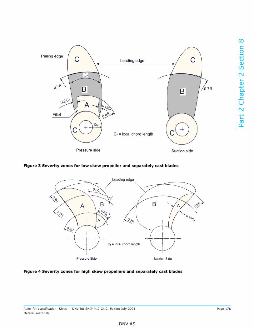
Figure 3 Severity zones for low skew propeller and separately cast blades
Figure 4 Severity zones for high skew propellers and separately cast blades
Part 2 Chapter 2 Section 8
Rules for classification: Ships — DNV-RU-SHIP Pt.2 Ch.2. Edition July 2021 Page 176Metallic materials
DNV AS

Figure 5 Severity zones for separately cast propeller hubs
Figure 6 Severity zones for controllable pitch propellers
Part 2 Chapter 2 Section 8
Rules for classification: Ships — DNV-RU-SHIP Pt.2 Ch.2. Edition July 2021 Page 177Metallic materials
DNV AS

Table 8 Chemical composition limits 1) for steel propeller castings
Alloy type Steel grade C Si Mn P S Cr Mo Ni
NV C12Cr1Ni 0.15 1.5 1.0 0.035 0.025 11.5 to 14.0 1.0 0.4 to 2.0
NV C13Cr4Ni 0.06 1.0 1.5 0.035 0.025 11.5 to 14.0 1.0 3.5 to 5.0Martensitic
NV C16Cr5Ni 0.06 1.0 1.0 0.035 0.025 15.0 to 17.5 1.5 3.5 to 6.0
Austenitic NV C19Cr11Ni 0.12 1.5 1.5 0.040 0.030 17.0 to 21.0 2.0 to 4.0 9.0 to 13.0
1) Given value is maximum content ([%] by weight) unless shown as a range or as a minimum.
Table 9 Mechanical properties for steel propeller castings
Charpy V-notch 1)
Alloy type Steel gradeProof stressRp0.2 minimum
[N/mm2]
Tensilestrength
Rmminimum
[N/mm2]
ElongationA5 minimum
[%]
Reductionof area Zminimum
[%]
Testtemperature
[°C]
Minimumaverageenergy
[J]
NV C12Cr1Ni 440 590 15 30 –10 20
NV C13Cr4Ni 550 750 15 35 –10 30Martensitic
NV C16Cr5Ni 540 760 15 35 –10 30
Austenitic NV C19Cr11Ni 180 2) 440 30 40 - -
1) Testing is required only for relevant class notations covered under Pt.6 Ch.6.2) Rp1.0 value is 205 N/mm
2.
Table 10 Allowable number and size of indications depending on severity zones
Severity zone Maximum numberof indications Indication type Maximum number
for each type 1, 2)Maximum lengthof indication [mm]
Non-linear 5 4A 7
Linear or aligned 2 3
Non-linear 10 6B 14
Linear or aligned 4 6
Non-linear 14 8C 20
Linear or aligned 6 6
1) Single non-linear indications less than 2 mm in zone A and less than 3 mm in other zones may be disregarded.2) The total number of non-linear indications may be increased to the maximum total number, or part thereof,
represented by the absence of linear or aligned indications.
Part 2 Chapter 2 Section 8
Rules for classification: Ships — DNV-RU-SHIP Pt.2 Ch.2. Edition July 2021 Page 178Metallic materials
DNV AS

5 Castings for boilers, pressure vessels and piping systems
5.1 Scope
5.1.1 These requirements are supplementary to the requirements in [1] and apply to steel castings forboilers, pressure vessels and piping systems where the design temperature is not lower than 0°C. Provisionis made for carbon and carbon-manganese steels and alloy steels.Requirements for castings for pressure vessel and piping for cold climate ships are given in Pt.6 Ch.6.
5.2 Chemical composition
5.2.1 The chemical composition shall comply with the overall limits given in Table 11 or, where applicable,the requirements of the approved specification.
Table 11 Chemical composition limits 1) for steel castings for boilers, pressure vessels and pipingsystems
Steeltype Steel grade C Si Mn P S Cr 2) Mo 2) Ni 2) Cu 2) V 2)
Total
residuals
NV C450HCandC-Mn NV C490H
0.25 0.60 0.50 to1.20 0.035 0.035 0.40 0.15 0.40 0.40 0.03 1.00
NV C0.5Mo 0.23 0.60 0.50 to1.00 0.035 0.035 0.30
0.40to0.65
0.40 0.40 0.05 -
NV C1Cr0.5Mo 0.20 0.60 0.50 to1.00 0.035 0.035
1.00to1.50
0.45to0.65
0.40 0.40 0.05 -Alloy
NV C2.25Cr1Mo 0.20 0.60 0.40 to0.90 0.035 0.035
2.00to2.75
0.90to1.20
0.40 0.40 0.05 -
1) Given value is maximum content ([%] by weight) unless shown as a range or as a minimum.2) Elements are considered as residual elements unless shown as a range or as a minimum.
5.3 Heat treatment
5.3.1 Carbon and carbon-manganese steel castings shall be supplied in one of the following conditions:
— normalised— normalised and tempered at a temperature of not less than 550°C— quenched and tempered at a temperature of not less than 550°C.
5.3.2 Alloy steel castings shall be normalised and tempered or quenched and tempered at a temperatureof not less than 550°C. For grades and heat treatment conditions not specified in [5.3.2], the specifiedmechanical properties shall be agreed with the Society.
Part 2 Chapter 2 Section 8
Rules for classification: Ships — DNV-RU-SHIP Pt.2 Ch.2. Edition July 2021 Page 179Metallic materials
DNV AS

5.4 Mechanical properties
5.4.1 The mechanical properties shall comply with the values given in Table 12 or, where applicable, therequirements of the approved specification.
Table 12 Mechanical properties for steel castings for boilers, pressure vessels and piping systems
Steel type Steel gradeYield strengthRp0.2 min.
[N/mm2]
Tensilestrength Rm[N/mm2]
ElongationA5 min.
[%]
Reduction ofarea Z min.
[%]
Charpy V-notch min.average energy [J], attest temperature 20°C
NV C450H 240 450 to 600 22 35 27C and C-Mn
NV C490H 275 490 to 640 18 30 27
NV C0.5Mo 250 450 to 600 21 35 27
NV C1Cr 0.5Mo 275 480 to 630 17 35 27
NV C2.25Cr1Mo N
(Normalised)275 480 to 630 17 35 27
Alloy
NVC2.25Cr1MoQT
(Quenched+ tempered)
380 580 to 730 16 35 27
5.5 Inspection
5.5.1 For each test unit, at least one casting is subject to magnetic particle testing, as well as to ultrasonic orradiographic testing.Subject to assessment by the Society, where a number of castings representing multiple test units are madefrom the same pattern, as an alternative testing of the first three castings made from the pattern may besubstituted for the testing of each test unit. In case the pattern is used for several years for various testunits, at least once per year NDT shall be performed.In addition, NDT shall be carried out as specified in the relevant construction rules.
5.5.2 All castings repaired by welding shall be non-destructive tested.
5.6 Pressure testing
5.6.1 Pressure retaining castings shall be tested after machining to the test pressure required by therelevant design and construction parts of the rules. No leaks are permitted.
6 Ferritic steel castings for low temperature service
6.1 Scope
6.1.1 These requirements are supplementary to the requirements in [1] and apply to ferritic steel castingsfor liquefied gas cargo and process piping where the design temperature is below 0°C. Provision is made for
Part 2 Chapter 2 Section 8
Rules for classification: Ships — DNV-RU-SHIP Pt.2 Ch.2. Edition July 2021 Page 180Metallic materials
DNV AS
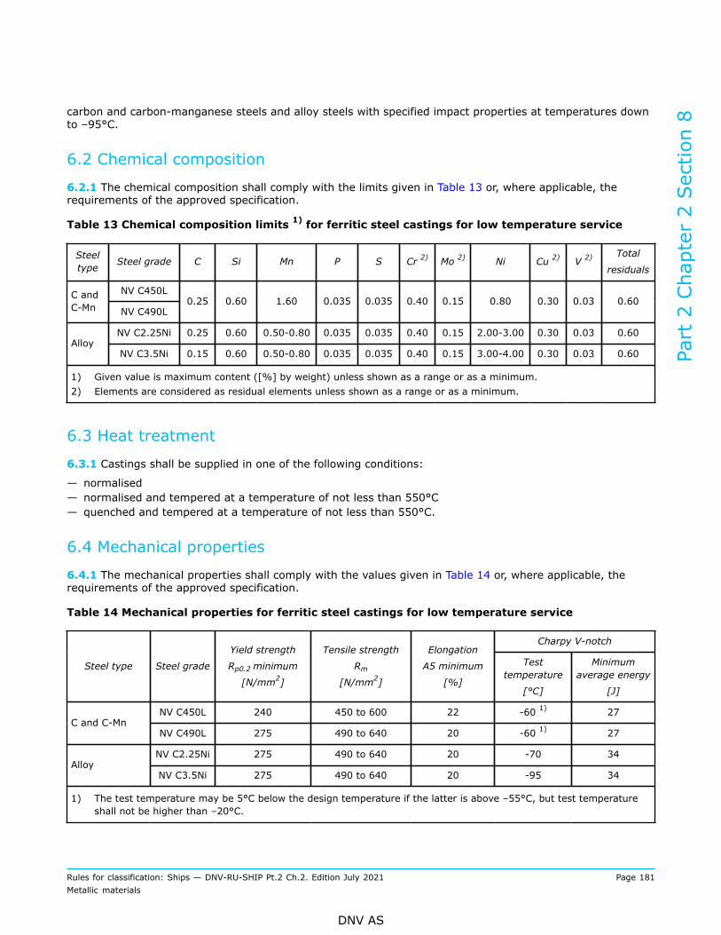
carbon and carbon-manganese steels and alloy steels with specified impact properties at temperatures downto –95°C.
6.2 Chemical composition
6.2.1 The chemical composition shall comply with the limits given in Table 13 or, where applicable, therequirements of the approved specification.
Table 13 Chemical composition limits 1) for ferritic steel castings for low temperature service
Steeltype Steel grade C Si Mn P S Cr 2) Mo 2) Ni Cu 2) V 2)
Total
residuals
NV C450LC andC-Mn NV C490L
0.25 0.60 1.60 0.035 0.035 0.40 0.15 0.80 0.30 0.03 0.60
NV C2.25Ni 0.25 0.60 0.50-0.80 0.035 0.035 0.40 0.15 2.00-3.00 0.30 0.03 0.60Alloy
NV C3.5Ni 0.15 0.60 0.50-0.80 0.035 0.035 0.40 0.15 3.00-4.00 0.30 0.03 0.60
1) Given value is maximum content ([%] by weight) unless shown as a range or as a minimum.2) Elements are considered as residual elements unless shown as a range or as a minimum.
6.3 Heat treatment
6.3.1 Castings shall be supplied in one of the following conditions:
— normalised— normalised and tempered at a temperature of not less than 550°C— quenched and tempered at a temperature of not less than 550°C.
6.4 Mechanical properties
6.4.1 The mechanical properties shall comply with the values given in Table 14 or, where applicable, therequirements of the approved specification.
Table 14 Mechanical properties for ferritic steel castings for low temperature service
Charpy V-notch
Steel type Steel grade
Yield strength
Rp0.2 minimum
[N/mm2]
Tensile strength
Rm[N/mm2]
Elongation
A5 minimum
[%]
Testtemperature
[°C]
Minimumaverage energy
[J]
NV C450L 240 450 to 600 22 -60 1) 27C and C-Mn
NV C490L 275 490 to 640 20 -60 1) 27
NV C2.25Ni 275 490 to 640 20 -70 34Alloy
NV C3.5Ni 275 490 to 640 20 -95 34
1) The test temperature may be 5°C below the design temperature if the latter is above –55°C, but test temperatureshall not be higher than –20°C.
Part 2 Chapter 2 Section 8
Rules for classification: Ships — DNV-RU-SHIP Pt.2 Ch.2. Edition July 2021 Page 181Metallic materials
DNV AS

6.5 Inspection
6.5.1 For each test unit, at least one casting shall be subjected to magnetic particle testing, as well as toultrasonic or radiographic testing.Subject to assessment by the Society, where a number of castings representing multiple test units are madefrom the same pattern, as an alternative testing of the first three castings made from the pattern may besubstituted for the testing of each test unit. In case the pattern is used for several years for various testunits, at least once per year NDT shall be performed.In addition, NDT shall be carried out as specified in the relevant construction rules.
6.5.2 All castings repaired by welding shall be non-destructive tested.
6.6 Pressure testing
6.6.1 Pressure retaining castings shall be tested, after machining, in accordance with a recognised testingstandard to the test pressure and time required by the relevant design and construction parts of the rules. Noleaks are permitted.
7 Stainless steel castings
7.1 Scope
7.1.1 These requirements are supplementary to the requirements in [1] and apply to stainless steel castingsfor use in piping systems for chemicals and liquefied gases, and duplex (ferritic/austenitic) stainless steels forchemicals, and cast sleeves and bushings for propeller shafts and rudder stocks.
7.1.2 The austenitic steels may be used for pressure retaining applications where the design temperatureis not lower than -165°C. Limitation to upper temperature for austenitic steels shall be assessed basedon high temperature properties, also considering corrosion in the applicable environment of exposure.Duplex (ferritic/austenitic) stainless steels may be used for pressure retaining applications where the designtemperature is not lower than -46°C, and if exposed to saliferous atmosphere, not higher than 100°C forGX 2 CrNiMoN 22 5 3 and not higher than 110°C for GX 2 CrNiMoCuN 25 6 3 3 and GX 2 CrNiMoN 26 7 4,respectively. Design temperatures outside these ranges are subject to approval.
7.2 Chemical composition
7.2.1 The chemical composition shall comply with the overall limits given in Table 15 or, where applicable,the requirements of the approved specification.
Table 15 Chemical composition limits 1) for stainless steel castings
Steel type C Si Mn P S Cr Mo Ni
Austenitic stainless steels
GX 2 CrNi 18 10 (304L) 0.03 2.0 1.5 0.040 0.030 17.0 to 21.0 - 8.0 to 12.0
GX 5 CrNi 19 9 (304) 0.08 2.0 1.5 0.040 0.030 18.0 to 21.0 - 8.0 to 11.0
GX 6 CrNiNb 19 10 (347) 2) 0.08 2.0 1.5 0.040 0.030 18.0 to 21.0 - 9.0 to 12.0
Part 2 Chapter 2 Section 8
Rules for classification: Ships — DNV-RU-SHIP Pt.2 Ch.2. Edition July 2021 Page 182Metallic materials
DNV AS
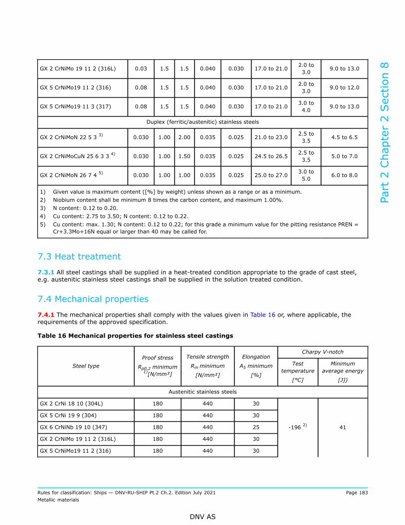
GX 2 CrNiMo 19 11 2 (316L) 0.03 1.5 1.5 0.040 0.030 17.0 to 21.0 2.0 to3.0 9.0 to 13.0
GX 5 CrNiMo19 11 2 (316) 0.08 1.5 1.5 0.040 0.030 17.0 to 21.0 2.0 to3.0 9.0 to 12.0
GX 5 CrNiMo19 11 3 (317) 0.08 1.5 1.5 0.040 0.030 17.0 to 21.0 3.0 to4.0 9.0 to 13.0
Duplex (ferritic/austenitic) stainless steels
GX 2 CrNiMoN 22 5 3 3) 0.030 1.00 2.00 0.035 0.025 21.0 to 23.0 2.5 to3.5 4.5 to 6.5
GX 2 CrNiMoCuN 25 6 3 3 4) 0.030 1.00 1.50 0.035 0.025 24.5 to 26.5 2.5 to3.5 5.0 to 7.0
GX 2 CrNiMoN 26 7 4 5) 0.030 1.00 1.00 0.035 0.025 25.0 to 27.0 3.0 to5.0 6.0 to 8.0
1) Given value is maximum content ([%] by weight) unless shown as a range or as a minimum.2) Niobium content shall be minimum 8 times the carbon content, and maximum 1.00%.3) N content: 0.12 to 0.20.4) Cu content: 2.75 to 3.50; N content: 0.12 to 0.22.5) Cu content: max. 1.30; N content: 0.12 to 0.22; for this grade a minimum value for the pitting resistance PREN =
Cr+3.3Mo+16N equal or larger than 40 may be called for.
7.3 Heat treatment
7.3.1 All steel castings shall be supplied in a heat-treated condition appropriate to the grade of cast steel,e.g. austenitic stainless steel castings shall be supplied in the solution treated condition.
7.4 Mechanical properties
7.4.1 The mechanical properties shall comply with the values given in Table 16 or, where applicable, therequirements of the approved specification.
Table 16 Mechanical properties for stainless steel castings
Charpy V-notch
Steel typeProof stress
Rp0.2 minimum1)[N/mm²]
Tensile strength
Rm minimum
[N/mm²]
Elongation
A5 minimum
[%]
Testtemperature
[°C]
Minimumaverage energy
[J])
Austenitic stainless steels
GX 2 CrNi 18 10 (304L) 180 440 30
GX 5 CrNi 19 9 (304) 180 440 30
GX 6 CrNiNb 19 10 (347) 180 440 25
GX 2 CrNiMo 19 11 2 (316L) 180 440 30
GX 5 CrNiMo19 11 2 (316) 180 440 30
-196 2) 41
Part 2 Chapter 2 Section 8
Rules for classification: Ships — DNV-RU-SHIP Pt.2 Ch.2. Edition July 2021 Page 183Metallic materials
DNV AS

GX 5 CrNiMo19 11 3 (317) 180 440 30
Duplex (ferritic/austenitic) stainless steels
GX 2 CrNiMoN 22 5 3 395 600 - 800 20 -203) 30
GX 2 CrNiMoCuN 25 6 3 3 455 650 - 850 22 -203) 50
GX 2 CrNiMoN 26 7 4 455 650 - 850 22 -203) 50
1) The minimum Rp1.0 value is 25 N/mm2 higher.
2) Unless otherwise specified in the referring rules, impact tests may be omitted if the design temperature is above –105°C.
3) To be tested at minimum design temperature if this is lower than -20°C. For minimum design temperature in therange -20°C to RT, testing at minimum design temperature is accepted. For minimum design temperature > RT,testing shall be done at a temperature ≤ RT.
7.5 Corrosion tests
7.5.1 Where requested by the relevant construction rules or specified for the order in question, the materialsfor piping systems for chemicals shall be subjected to corrosion test as specified in Sec.3 [4.6].
7.6 Inspection
7.6.1 For each test unit, at least one casting shall be subject to liquid penetrant testing (PT), as well as toultrasonic or radiographic testing.Subject to assessment by the Society, where a number of castings representing multiple test units are madefrom the same pattern, as an alternative testing of the first three castings made from the pattern may besubstituted for the testing of each test unit. In case the pattern is used for several years for various testunits, at least once per year NDT shall be performed.In addition, NDT shall be carried out as specified in the relevant construction rules.
7.6.2 All castings repaired by welding shall be non-destructive tested.
7.7 Pressure testing
7.7.1 Pressure retaining castings shall be tested, after machining, in accordance with a recognised testingstandard to the test pressure and time required by the relevant design and construction parts of the rules. Noleaks are permitted.
Part 2 Chapter 2 Section 8
Rules for classification: Ships — DNV-RU-SHIP Pt.2 Ch.2. Edition July 2021 Page 184Metallic materials
DNV AS
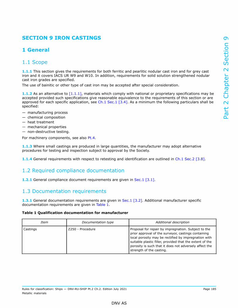
SECTION 9 IRON CASTINGS
1 General
1.1 Scope
1.1.1 This section gives the requirements for both ferritic and pearlitic nodular cast iron and for grey castiron and it covers IACS UR W9 and W10. In addition, requirements for solid solution strengthened nodularcast iron grades are specified.The use of bainitic or other type of cast iron may be accepted after special consideration.
1.1.2 As an alternative to [1.1.1], materials which comply with national or proprietary specifications may beaccepted provided such specifications give reasonable equivalence to the requirements of this section or areapproved for each specific application, see Ch.1 Sec.1 [3.4]. As a minimum the following particulars shall bespecified:
— manufacturing process— chemical composition— heat treatment— mechanical properties— non-destructive testing.
For machinery components, see also Pt.4.
1.1.3 Where small castings are produced in large quantities, the manufacturer may adopt alternativeprocedures for testing and inspection subject to approval by the Society.
1.1.4 General requirements with respect to retesting and identification are outlined in Ch.1 Sec.2 [3.8].
1.2 Required compliance documentation
1.2.1 General compliance document requirements are given in Sec.1 [3.1].
1.3 Documentation requirements
1.3.1 General documentation requirements are given in Sec.1 [3.2]. Additional manufacturer specificdocumentation requirements are given in Table 1.
Table 1 Qualification documentation for manufacturer
Item Documentation type Additional description
Castings Z250 - Procedure Proposal for repair by impregnation. Subject to theprior approval of the surveyor, castings containinglocal porosity may be rectified by impregnation withsuitable plastic filler, provided that the extent of theporosity is such that it does not adversely affect thestrength of the casting.
Part 2 Chapter 2 Section 9
Rules for classification: Ships — DNV-RU-SHIP Pt.2 Ch.2. Edition July 2021 Page 185Metallic materials
DNV AS

1.4 Survey, inspection and testing requirements
1.4.1 General survey, inspection and testing requirements are given in Ch.1 Sec.1 [3.3]. Additional specificrequirements are given in Table 2, as further detailed in this section.
Table 2 Additional survey and testing requirements
Survey, inspection and testing item Description
Chemical composition Required for all materials.
Mechanical testing Required for all grades in accordance with the requirements of therelevant section.
Impact toughness test Relevant for all grades where specified in the following sections.
Metallographic examination For nodular cast iron samples for metallographic examinationshall be prepared for every ladle of metal, treated to producenodular graphite.
Pressure test When required by the relevant construction Rules, castings shallbe pressure tested before final acceptance.
Visual inspection The manufacturer shall carry out visual inspection of all castingon accessible surfaces for surface finish and compliance with thedimensional and geometrical tolerances.
Visual survey Castings for which certification by the Society is required shall bepresented to the surveyor for visual inspection. The surveyor mayrequire areas to be etched for the purpose of investigating weldrepairs.
Repair At the discretion of the surveyor, small surface blemishes maybe removed by local grinding within the negative tolerance of thewall thickness.
1.5 Quality of castings
1.5.1 All castings shall have a clean surface compatible with the conditions of manufacture. Minor castingdefects such as sand and slag marks, small cold shuts and scabs may be trimmed off within the negativetolerance on the wall thickness. The manufacturer shall make sure that the castings are free from externaland internal defects liable to impair their subsequent use, including the machining operations, to more thanan insignificant extent.
Guidance note:Where it is relevant for purchaser to specify more detailed surface quality requirements, reference should be made to a relevantstandard, e.g. EN 1369, EN 1371-1, EN 12680-3 or EN 12681.
---e-n-d---o-f---g-u-i-d-a-n-c-e---n-o-t-e---
1.6 Manufacture
1.6.1 All castings delivered with NV or works certificate shall be made at foundries approved by the Society,see Ch.1 Sec.2 [2.2.2].
Part 2 Chapter 2 Section 9
Rules for classification: Ships — DNV-RU-SHIP Pt.2 Ch.2. Edition July 2021 Page 186Metallic materials
DNV AS

1.6.2 Suitable mechanical methods shall be employed for the removal of surplus material from castings.Thermal cutting processes are not acceptable, except as a preliminary operation to mechanical methods.
1.6.3 Where castings of the same type are regularly produced in quantity, the manufacturer shall, inagreement with the Society, make all tests necessary to prove the quality of the prototype castings and isalso to make periodical examinations to verify the continued efficiency of the manufacturing technique. Thesurveyor shall be given the opportunity to witness tests.
1.7 Chemical composition
1.7.1 Unless especially required, the chemical composition is left to the discretion of the manufacturer, whoshall ensure that it is suitable to obtain the mechanical properties specified for the casting.
1.8 Condition of supply and heat treatment
1.8.1 Except as given in [1.8.2], the castings may be supplied either in the as cast condition or in the heat-treated condition.
1.8.2 For some applications, such as high temperature service or where dimensional stability is important,castings may require to be given a suitable tempering or stress relieving heat treatment.
1.9 Testing
1.9.1 Test material sufficient for the required tests and for possible re-tests shall be provided for eachcasting or batch of castings. Separately cast test samples are normally to be used.
1.9.2 The separately cast test samples shall be cast in moulds made from the same type of material asused for the castings. The test samples shall not be stripped from the moulds until the temperature is below500°C. In the case of chill casting, centrifugal casting and continuous casting, special agreements shall bereached with the Society regarding the selection of samples.
1.9.3 Where castings are supplied in the heat-treated condition, the test samples shall be heat-treatedtogether with the castings which they represent. For cast-on samples the sample shall not be cut off from thecasting until after the heat treatment.
1.9.4 A batch testing procedure may be adopted for castings with a fettled mass of 1 tonne or less. Allcastings in a batch shall be of similar type and dimensions, and cast from the same ladle of treated metal.One test sample shall be provided for each multiple of 2.0 tonnes of fettled castings in each batch.
1.9.5 For large castings where more than one ladle of treated metal is used, additional test samples shall beprovided so as to be representative of each ladle used.
1.9.6 All test samples shall be suitably marked to identify them with the castings which they represent.
1.10 Visual and non-destructive examination
1.10.1 The manufacturer shall do visual inspection of all castings on all accessible surfaces. The castingsshall comply with specified surface finish, dimensions and geometrical tolerances. Where applicable, this shallinclude the inspection of internal surfaces and bores. All surfaces shall be cleaned and adequately preparedfor examination. The surfaces shall not be hammered, peened or treated in any way which may obscuredefects.
Part 2 Chapter 2 Section 9
Rules for classification: Ships — DNV-RU-SHIP Pt.2 Ch.2. Edition July 2021 Page 187Metallic materials
DNV AS
1.10.2 Before acceptance, all castings shall be visually examined including, where applicable, the internalsurfaces. Unless otherwise agreed, the verification of dimensions is the responsibility of the manufacturer.
1.10.3 NDT other than visual examination is not required unless otherwise specified, e.g. by the applicabledesign and construction rules.The surveyor may require areas to be examined by suitable means of NDT for the purpose of investigatingthe soundness of the casting.
1.10.4 When required by the relevant design and construction parts of the rules, castings shall be tested,after machining, in accordance with a recognised testing standard to the test pressure and time before finalacceptance.
1.10.5 In the event of any casting is proved defective during subsequent machining or testing it shall berejected notwithstanding any previous certification.
1.10.6 The surveyor may require areas to be etched for the purpose of investigating weld repairs.
1.11 Repair of defects
1.11.1 At the discretion of the surveyor, small surface blemishes may be removed by local grinding withinthe negative tolerance of the wall thickness. Castings shall be free from defects liable to impair machiningoperations and their subsequent use to a more than an insignificant extent.
1.11.2 Subject to the prior approval of the surveyor, castings containing local porosity may be rectifiedby impregnation with suitable plastic filler, provided that the extent of the porosity is such that it does notadversely affect the strength of the casting.
1.11.3 Repairs by welding are not permitted, unless especially considered and accepted.
2 Nodular cast iron
2.1 Scope
2.1.1 This subsection gives the specific requirements to nodular cast iron.
2.2 Test material
2.2.1 The following requirements are given in addition to [1.9].
2.2.2 The test samples shall be one of the standard types detailed in Figure 1, Figure 2 and Figure 3 witha thickness of 25 mm. Test samples of other dimensions may, however, be specially required for somecomponents.
Part 2 Chapter 2 Section 9
Rules for classification: Ships — DNV-RU-SHIP Pt.2 Ch.2. Edition July 2021 Page 188Metallic materials
DNV AS

Figure 1 Type A test samples (U-type)
Figure 2 Type B test samples (double U-type)
Part 2 Chapter 2 Section 9
Rules for classification: Ships — DNV-RU-SHIP Pt.2 Ch.2. Edition July 2021 Page 189Metallic materials
DNV AS
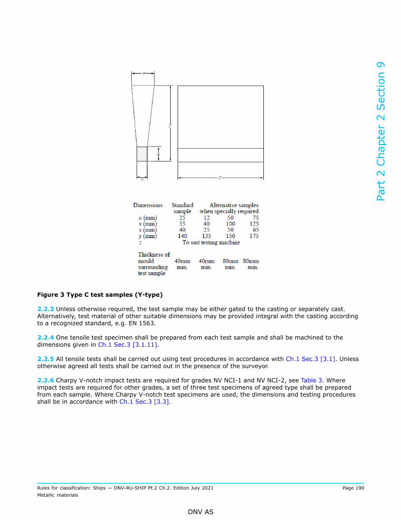
Figure 3 Type C test samples (Y-type)
2.2.3 Unless otherwise required, the test sample may be either gated to the casting or separately cast.Alternatively, test material of other suitable dimensions may be provided integral with the casting accordingto a recognized standard, e.g. EN 1563.
2.2.4 One tensile test specimen shall be prepared from each test sample and shall be machined to thedimensions given in Ch.1 Sec.3 [3.1.11].
2.2.5 All tensile tests shall be carried out using test procedures in accordance with Ch.1 Sec.3 [3.1]. Unlessotherwise agreed all tests shall be carried out in the presence of the surveyor.
2.2.6 Charpy V-notch impact tests are required for grades NV NCI-1 and NV NCI-2, see Table 3. Whereimpact tests are required for other grades, a set of three test specimens of agreed type shall be preparedfrom each sample. Where Charpy V-notch test specimens are used, the dimensions and testing proceduresshall be in accordance with Ch.1 Sec.3 [3.3].
Part 2 Chapter 2 Section 9
Rules for classification: Ships — DNV-RU-SHIP Pt.2 Ch.2. Edition July 2021 Page 190Metallic materials
DNV AS

2.3 Mechanical properties
2.3.1 Ferritic nodular cast iron with special requirements shall meet the values for grade NV NCI-1 and NVNCI-2, given in Table 3.
2.3.2 Nodular cast iron for ordinary use shall be in accordance with the requirements for grades NV NCI370to NV NCI800, given in Table 3. Values for elongation which correspond to the tensile strengths betweenthe values specified, shall be calculated by linear interpolation, i.e. relative to the specified minimum tensilestrength.
2.3.3 Mechanical properties for integrally cast specimens shall be agreed with the Society.
Table 3 Nodular cast iron - mechanical properties of separately cast test samples
Charpy V-notch impactenergy, average
GradeTensile strength1) Rm minimum
[N/mm2]
Proof stress2) Rp0.2minimum
[N/mm2]
Elongation A5
[%] Minimum 3)
[J]
Testtemperature4)
[°C]
Hardness5)
[HB]
Ferritic:
NV NCI-1 350 220 22 12 (9) - 40 110 to 170
NV NCI-2 400 250 18 12 (9) - 20 140 to 200
NV NCI370 370 230 17 - - 120 to 180
NV NCI400 400 250 12 - - 140 to 200
Ferritic (solid solution strengthened):
NVNCI450-18 450 350 18 - - 170 to 200
NVNCI500-14 500 400 14 - - 185 to 215
NVNCI600-10 600 470 10 - - 200 to 230
Ferritic-pearlitic:
NV NCI500-7 500 320 7 - - 170 to 240
NV NCI600-3 600 370 3 - - 190 to 270
Pearlitic or tempered structure:
NV NCI700 700 420 2 - - 230 to 300
NV NCI800 800 480 2 - - 250 to 350
Part 2 Chapter 2 Section 9
Rules for classification: Ships — DNV-RU-SHIP Pt.2 Ch.2. Edition July 2021 Page 191Metallic materials
DNV AS

1) For intermediate values of specified minimum tensile strength, the minimum values for 0.2% proof and elongationmay be obtained by interpolation (relative to the specified minimum tensile strength).
2) The 0.2% proof stress values are given for information purposes and unless otherwise agreed do not require to beverified by test. In the case of ferritic grades, the yield point revealed by the curve plotted by the testing machinemay be stated instead of the 0.2% proof stress.
3) The average value measured on 3 Charpy V-notch specimens one result may be below the average value but notless than the minimum shown in brackets. If the impact testing is carried out at +20°C the impact energy shall notbe less than 17 (14) and 14 (11) J, respectively, for NV NCI-1 and NV NCI-2.
4) When impact testing is required for a specific temperature (e.g. -10°C), the results for impact testing performed atlower temperatures (e.g. -20°C, -40°C) are acceptable as well.
5) Hardness values are given for information and need not to be tested unless specifically required by the purchaser.
2.4 Metallographic examination
2.4.1 Each sample as defined in [2.2] shall be subjected to metallographic examination. At least 90% of thegraphite shall be in spheroidal form.
Guidance note:Graphite types I and II according to plate I of ASTM A247 are considered to have a spheroidal form.
---e-n-d---o-f---g-u-i-d-a-n-c-e---n-o-t-e---
3 Grey cast iron
3.1 Scope
3.1.1 This subsection gives the specific requirements to grey cast iron.
3.2 Test material
3.2.1 The following requirements are given in addition to [1.9].
3.2.2 Separately cast test samples in the form of bars 30 mm in diameter and of a suitable length shall beused unless otherwise agreed between the manufacturer and purchaser.When two or more test samples are cast simultaneously in a single mould, the bars shall be at least 50 mmapart as given in Figure 4.
Part 2 Chapter 2 Section 9
Rules for classification: Ships — DNV-RU-SHIP Pt.2 Ch.2. Edition July 2021 Page 192Metallic materials
DNV AS

Figure 4 Test sample for grey cast iron
3.2.3 Integrally cast samples may be used when a casting is more than 20 mm thick and its mass exceed200 kg, subject to agreement with the Society. The type and location of the sample shall be agreed, e.g.according to a recognized standard like EN 1561.
3.2.4 With the exception of [3.2.7], at least one test sample shall be cast with each batch.
3.2.5 With the exception of [3.2.7], a batch consists of the castings poured from a single ladle of metal,provided they are all of similar type and dimensions. A batch cannot exceed two tonnes of fettled castings. Asingle casting will constitute a batch if its mass is 2 tonnes or more.
3.2.6 For continuous melting of the same grade of cast iron in large tonnages the mass of a batch may beincreased to the output of 2 hours of pouring.
3.2.7 If one grade of cast iron is melted in large quantities and if production is carefully monitored bysystematic checking of the melting process, such as chill testing, chemical analysis or thermal analysis, testsamples may be taken at longer intervals.
3.2.8 One tensile test specimen shall be prepared from each test sample and for 30 mm diameter samplesshall be machined to the dimensions given in Ch.1 Sec.3 [3.1.12]. Where test samples of other dimensionsare specially required, the tensile test specimens shall be machined to agreed dimensions.
3.2.9 All tensile tests shall be carried out using test procedures in accordance with Ch.1 Sec.3 [3.1]. Unlessotherwise agreed all tests shall be carried out in the presence of the surveyor.
Part 2 Chapter 2 Section 9
Rules for classification: Ships — DNV-RU-SHIP Pt.2 Ch.2. Edition July 2021 Page 193Metallic materials
DNV AS
3.3 Mechanical properties
3.3.1 Only the tensile strength shall be determined. The results obtained from tests shall comply with theminimum value specified for the supplied casting. The specified minimum tensile strength shall not be lessthan 200 N/mm2.Mechanical properties for integrally cast specimens shall be agreed with the Society.
3.3.2 The fractured surfaces of all tensile test specimens shall be granular and grey in appearance.
Part 2 Chapter 2 Section 9
Rules for classification: Ships — DNV-RU-SHIP Pt.2 Ch.2. Edition July 2021 Page 194Metallic materials
DNV AS

SECTION 10 ALUMINIUM ALLOYS
1 Wrought aluminium alloys
1.1 Scope
1.1.1 This subsection specifies the requirements for aluminium alloy plates, sections, tubes and bars tobe used in the construction of hulls and other marine structures and for cryogenic applications. Theserequirements are applicable to wrought aluminium products within the thickness range of 3 mm to 50 mm.
1.1.2 Plates and sections with thickness less than 3 mm or more than 50 mm may be manufactured andtested in accordance with the requirements of a recognized standard or specification.
1.2 Required compliance documentation
1.2.1 General compliance document requirements are given in Sec.1 [3.1].
1.2.2 The product shall be delivered with the type of compliance document required in the relevantconstruction rules giving the following particulars for each test unit which has been accepted:
— purchaser's name, order number and vessel identification, where known— manufacturer’s name— number, dimensions and mass of the product— alloy grade and temper condition— identification marking— chemical composition— results of mechanical tests— results of any supplementary and additional test requirements specified.
1.2.3 Where the alloys are not cast in the same works in which they are made into semi-finished products, aworks (W) certificate giving chemical composition is required for each charge.Semi-finished products (ingots or extrusion billets) used as base material for wrought products shall bemade at works approved by the Society. The chemical composition analysis produced by the manufactureris normally accepted (works certificate), with the surveyor reserving the right to have occasional checkanalyses carried out.
1.3 Documentation requirements
1.3.1 General documentation requirements are given in Sec.1 [3.2]. Additional manufacturer specificdocumentation requirements are given in Table 1.
Table 1 Qualification documentation for manufacturer
Item Documentation type Additional description
Wrought aluminium alloys Reference micrographs When metallographic examination is used as analternative to corrosion test:
Upon satisfactory establishment of the relationshipbetween microstructure and resistance to corrosion,the reference photomicrographs and the results ofthe corrosion tests shall be approved by the Society.
Part 2 Chapter 2 Section 10
Rules for classification: Ships — DNV-RU-SHIP Pt.2 Ch.2. Edition July 2021 Page 195Metallic materials
DNV AS

1.4 Survey, inspection and testing requirements
1.4.1 General survey, inspection and testing requirements are given in Ch.1 Sec.1 [3.3]. Additional specificrequirements are given in Table 2, as further detailed in this section.
Table 2 Additional survey and testing requirements
Survey, inspection and testing item Description
Chemical composition Required for all materials.
Mechanical testing Required for all grades in accordance with the requirements of therelevant paragraph.
Macrosection test,
Drift expansion test
Manufacturer shall verify and document proper fusion of presswelds for closed section extrusions by macrosection tests or driftexpansion tests. Other tests may be accepted after consideration.The testing and test results shall be recorded.
The surveyor shall be given the opportunity to survey and checkthe sampling, testing, test laboratory, etc. at any time, and thetest records shall be presented to the surveyor on request.
Corrosion test Rolled 5000 series alloys of certain grades and tempers intendedfor use in marine hull construction or in marine applicationswhere frequent direct contact with seawater is expected shall betested with respect to exfoliation and inter-granular corrosionresistance.
Microstructure/metallographic evaluation As an alternative to corrosion test, the manufacturers mayestablish the relationship between microstructure and resistanceto corrosion, and evaluate corrosion resistance based onphotomicrographs.
Visual inspection Wrought aluminium products shall be subject to visual inspectionand measurements of dimensions by the manufacturer.
1.5 Materials
1.5.1 Alloy grades suitable for marine environment are listed in Table 3. The numerical designation (grade)of aluminium alloys are based on those of the Aluminium Association. Temper conditions (delivery heattreatment) are defined in EN 515 or ANSI H35.1.
1.5.2 Where required by the relevant design and construction parts of the rules, wrought aluminium alloysshall comply with the requirements of Ch.1 and the requirements of this subsection.As an alternative to [1.5.1], materials which comply with national or proprietary specifications may beaccepted provided such specifications give reasonable equivalence to the requirements of this section orare approved for each specific application. Generally, such materials shall comply with the appropriaterequirements of Ch.1 Sec.1 [3.4].
1.5.3 The use of 6000 series aluminium alloys in direct contact with sea water may be restricted dependingon application and corrosion protection system. The use of these alloys shall be agreed with the Society.
Part 2 Chapter 2 Section 10
Rules for classification: Ships — DNV-RU-SHIP Pt.2 Ch.2. Edition July 2021 Page 196Metallic materials
DNV AS

1.6 Manufacture
1.6.1 All wrought aluminium products delivered with NV or works (W) certificate shall be manufacturedat works approved by the Society, see Ch.1 Sec.2 [2.2.2]. The semi-finished products (ingots or extrusionbillets) used shall be made at works approved by the Society.
1.6.2 The alloys may be cast either in ingot moulds or by a continuous casting process. Plates shall beformed by rolling and may be hot or cold finished. Sections, bars and tubes may be formed by extrusion,rolling or drawing.
1.7 Chemical composition
1.7.1 The chemical composition of each cast shall, unless otherwise agreed, be determined by themanufacturer on a sample taken during the pouring of the cast. The chemical composition shall comply withthe limits given in Table 3.
Table 3 Chemical composition limits 1) for wrought aluminium alloys
Other elements 2)Grade Si Fe Cu Mn Mg Cr Zn Ti
Each Total
NV 5052 0.25 0.40 0.10 0.10 2.2 to2.8
0.15 to0.35 0.10 - 0.05 0.15
NV 5059 0.45 0.50 0.25 0.6 to1.2
5.0 to6.0 0.25 0.40
to 0.9 0.20 0.05 5) 0.15 5)
NV 5083 0.40 0.40 0.10 0.40to 1.0
4.0 to4.9
0.05 to0.25 0.25 0.15 0.05 0.15
NV 5086 0.40 0.50 0.10 0.20to 0.7
3.5 to4.5
0.05 to0.25 0.25 0.15 0.05 0.15
NV 5154A 0.50 0.50 0.10 0.50 3.1 to3.9 0.25 0.20 0.20 0.05 0.15
NV 5383 0.25 0.25 0.20 0.7 to1.0
4.0 to5.2 0.25 0.40 0.15 0.05 4) 0.15 4)
NV 5454 0.25 0.40 0.10 0.50to 1.0
2.4 to3.0
0.05 to0.20 0.25 0.20 0.05 0.15
NV 5456 0.25 0.40 0.10 0.50to 1.0
4.7 to5.5
0.05 to0.20 0.25 0.20 0.05 0.15
NV 5754 0.40 0.40 0.10 0.50 3) 2.6 to3.6 0.30 3) 0.20 0.15 0.05 0.15
NV 6005A 0.50to 0.9 0.35 0.30 0.50 6) 0.40
to 0.7 0.30 6) 0.20 0.10 0.05 0.15
NV 6060 0.30to 0.6
0.10 to0.30 0.10 0.10 0.35
to 0.6 0.05 0.15 0.10 0.05 0.15
NV 6061 0.40to 0.8 0.7 0.15 to
0.40 0.15 0.8 to1.2
0.04 to0.35 0.25 0.15 0.05 0.15
Part 2 Chapter 2 Section 10
Rules for classification: Ships — DNV-RU-SHIP Pt.2 Ch.2. Edition July 2021 Page 197Metallic materials
DNV AS

NV -6063 0.20to 0.6 0.35 0.10 0.10 0.45
to 0.9 0.10 0.10 0.10 0.05 0.15
NV 6082 0.7 to1.3 0.50 0.10 0.40
to 1.00.6 to1.2 0.25 0.20 0.10 0.05 0.15
1) Given value is maximum content ([%] by weight) unless shown as a range or as a minimum.2) Includes Ni, Ga, V and listed elements for which no specific limit is shown. Regular analysis need not be made.3) Mn + Cr: 0.10 to 0.60.4) Zr: maximum 0.20. The total for other elements does not include Zirconium.5) Zr: 0.05 to 0.25. The total for other elements does not include Zirconium.6) Mn + Cr: 0.12 to 0.50.
1.7.2 Other alloys or alloys which do not fully comply with Table 3 may be accepted after consideration ineach particular case. Special tests and other relevant information, e.g. which confirm satisfactory corrosionresistance and weldability, may be required.
1.8 Temper conditions
1.8.1 5000 series alloys shall be supplied in any of the temper conditions given in Table 4 and Table 5, asapplicable. 6000 series alloys shall be supplied in any of the temper conditions given in Table 5.
1.8.2 Unless otherwise approved, aluminium for cryogenic applications shall be of the 5000 series alloys andsupplied in the annealed condition.
1.9 Mechanical testing
1.9.1 The mechanical properties shall comply with the values given in Table 4 and Table 5, as applicable.Other temper conditions with related mechanical properties may be accepted by the Society afterconsideration in each particular case.
Table 4 Mechanical properties for rolled aluminium alloys
Elongation 2)
Grade TemperThickness, t
[mm]
Yield strength Rp0.2min. or range 1)
[MPa]
Tensile strengthRm min. or range
1)
[MPa]A50 mm min.
[%]
A5d min.
[%]
O t ≤ 50 65 165 to 215 19 18
t ≤ 6 130 210 to 260 10 -H32
6 < t ≤ 50 130 210 to 260 12 12
t ≤ 6 150 230 to 280 7 -
NV 5052
H346 < t ≤ 50 150 230 to 280 9 9
O t ≤ 50 160 330 - 24
H111 t ≤ 50 160 330 24 24
t ≤ 20 270 370 10 10H116
20 < t ≤ 50 260 360 10 10
NV 5059
H321 t ≤ 20 270 370 10 10
Part 2 Chapter 2 Section 10
Rules for classification: Ships — DNV-RU-SHIP Pt.2 Ch.2. Edition July 2021 Page 198Metallic materials
DNV AS

Elongation 2)
Grade TemperThickness, t
[mm]
Yield strength Rp0.2min. or range 1)
[MPa]
Tensile strengthRm min. or range
1)
[MPa]A50 mm min.
[%]
A5d min.
[%]
20 < t ≤ 50 260 360 10 10
O t ≤ 50 125 275 to 350 16 14
H111 t ≤ 50 125 275 to 350 16 14
H112 t ≤ 50 125 275 12 10
H116 t ≤ 50 215 305 10 10
H128 4 < t ≤ 8 215 305 to 385 10 -
NV 5083
H321 t ≤ 50 215 to 295 305 to 385 12 10
O t ≤ 50 95 240 to 305 16 14
H111 t ≤ 50 95 240 to 305 16 14
t ≤ 12.5 125 250 8 -H112
12.5 < t ≤ 50 105 240 - 9
t ≤ 6.3 195 275 8 -
NV 5086
H1166.3 < t ≤ 50 195 275 10 9
O t ≤ 50 85 215 to 275 17 16
t ≤ 6 180 250 to 305 8 -H32
6 < t ≤ 50 180 250 to 305 10 9NV 5154A
H34 t ≤ 50 200 270 to 325 8 7
O t ≤ 50 145 290 - 17
H111 t ≤ 50 145 290 - 17
H116 t ≤ 50 220 305 10 10NV 5383
H321 t ≤ 50 220 305 10 10
0 t ≤ 50 85 215 to 285 17 16
t ≤ 6 180 250 to 305 8 -H32
6 < t ≤ 50 180 250 to 305 10 9NV 5454
H34 t ≤ 50 200 270 to 325 8 7
t ≤ 6.3 130 to 205 290 to 365 16 -O
6.3 < t ≤ 50 125 to 205 285 to 360 16 14
H116 t ≤ 30 230 315 10 10
30 < t ≤ 40 215 305 - 10
40 < t ≤ 50 200 285 - 10
NV 5456
H321
t ≤ 12.5 230 to 315 315 to 405 12 -
Part 2 Chapter 2 Section 10
Rules for classification: Ships — DNV-RU-SHIP Pt.2 Ch.2. Edition July 2021 Page 199Metallic materials
DNV AS
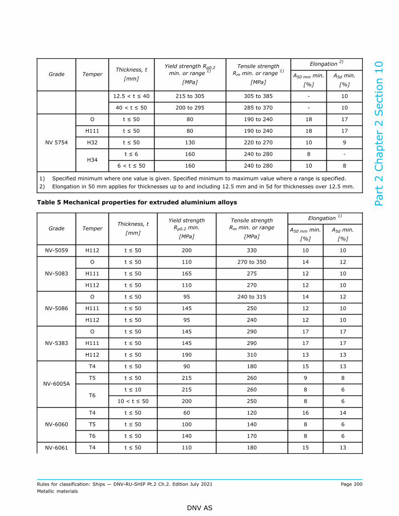
Elongation 2)
Grade TemperThickness, t
[mm]
Yield strength Rp0.2min. or range 1)
[MPa]
Tensile strengthRm min. or range
1)
[MPa]A50 mm min.
[%]
A5d min.
[%]
12.5 < t ≤ 40 215 to 305 305 to 385 - 10
40 < t ≤ 50 200 to 295 285 to 370 - 10
O t ≤ 50 80 190 to 240 18 17
H111 t ≤ 50 80 190 to 240 18 17
H32 t ≤ 50 130 220 to 270 10 9
t ≤ 6 160 240 to 280 8 -
NV 5754
H346 < t ≤ 50 160 240 to 280 10 8
1) Specified minimum where one value is given. Specified minimum to maximum value where a range is specified.2) Elongation in 50 mm applies for thicknesses up to and including 12.5 mm and in 5d for thicknesses over 12.5 mm.
Table 5 Mechanical properties for extruded aluminium alloys
Elongation 1)
Grade TemperThickness, t
[mm]
Yield strengthRp0.2 min.
[MPa]
Tensile strengthRm min. or range
[MPa]A50 mm min.
[%]
A5d min.
[%]
NV-5059 H112 t ≤ 50 200 330 10 10
O t ≤ 50 110 270 to 350 14 12
H111 t ≤ 50 165 275 12 10NV-5083
H112 t ≤ 50 110 270 12 10
O t ≤ 50 95 240 to 315 14 12
H111 t ≤ 50 145 250 12 10NV-5086
H112 t ≤ 50 95 240 12 10
O t ≤ 50 145 290 17 17
H111 t ≤ 50 145 290 17 17NV-5383
H112 t ≤ 50 190 310 13 13
T4 t ≤ 50 90 180 15 13
T5 t ≤ 50 215 260 9 8
t ≤ 10 215 260 8 6NV-6005A
T610 < t ≤ 50 200 250 8 6
T4 t ≤ 50 60 120 16 14
T5 t ≤ 50 100 140 8 6NV-6060
T6 t ≤ 50 140 170 8 6
NV-6061 T4 t ≤ 50 110 180 15 13
Part 2 Chapter 2 Section 10
Rules for classification: Ships — DNV-RU-SHIP Pt.2 Ch.2. Edition July 2021 Page 200Metallic materials
DNV AS

Elongation 1)
Grade TemperThickness, t
[mm]
Yield strengthRp0.2 min.
[MPa]
Tensile strengthRm min. or range
[MPa]A50 mm min.
[%]
A5d min.
[%]
T5 t ≤ 50 205 240 6 7
T6 t ≤ 50 240 260 10 8
T4 t ≤ 50 65 130 14 12
T5 t ≤ 50 110 150 8 7NV-6063
T6 t ≤ 50 170 205 10 9
T4 t ≤ 50 110 205 14 12
T5 t ≤ 50 230 270 8 6
t ≤ 5 250 290 6 -NV-6082
T65 < t ≤ 50 260 310 10 8
1) Elongation in 50 mm applies for thicknesses up to and including 12.5 mm and in 5d for thicknesses over 12.5 mm.
1.9.2 All materials in a test unit (lot) shall be of the same production process, alloy grade, temper, cast,product form (plates, sections etc.) and thickness. Artificially aged grades are in addition to be from thesame furnace charge.
1.9.3 For rolled products, one tensile test is required for each 2000 kg, or fraction thereof, in each test unit.For single plates or for coils weighing more than 2000 kg, only one tensile test per plate or coil is required.
1.9.4 For extruded products with a nominal mass of less than 1 kg/m, one tensile test is required for each1000 kg, or fraction thereof, in each test unit. For nominal masses between 1 and 5 kg/m, one tensile test isrequired for each 2000 kg, or fraction thereof, in each test unit. Where the nominal mass exceeds 5 kg/m,one tensile test is required for each 3000 kg, or fraction thereof, in each test unit.
1.9.5 For rolled products, the test material shall be taken at one third of the width from a longitudinal edge.The test specimens are normally to be cut with their longitudinal axis transverse to the final rolling direction.If the width is less than 300 mm, longitudinal tests will be permitted.
1.9.6 For extruded products, the test material shall be taken in the range 1/3 to 1/2 of the distance from theedge to the centre of the thickest part of the section. The test specimens are normally to be cut with theirlongitudinal axes parallel to the extruding direction.
1.9.7 The size, thickness location and preparation of test specimens and the procedures used for mechanicaltesting shall comply with the relevant requirements of Ch.1 Sec.3 [3.1.10].
1.10 Press weld testing of closed sections
1.10.1 Proper fusion of press welds for closed section extrusions shall be verified either by macrosectiontests or by drift expansion tests. Other tests may be accepted after consideration.For closed sections affecting the global strength of the vessel, every fifth section shall be sampled onesection. Sections with lengths exceeding 6 m shall be sampled every section in the start of the production.The number of tests may be reduced to every fifth section if the results from the first three sections arefound acceptable. Every sample section shall be tested at both ends.
Part 2 Chapter 2 Section 10
Rules for classification: Ships — DNV-RU-SHIP Pt.2 Ch.2. Edition July 2021 Page 201Metallic materials
DNV AS

For sections for structures not affecting the global strength of the vessel (e.g. helidecks), the extent of pressweld testing structures may be reduced as agreed with the Society, e.g. typical minimum extent of testingwould be:
a) testing of the two first sections and of the last section of each cast and each production batch, andb) one test from each heat treatment batch if this is less than that given by a).
1.10.2 Where verification is by macrosection tests, no indication of lack of fusion at the press welds ispermitted.
1.10.3 Where verification is by drift expansion test, the test specimens shall be cut with the endsperpendicular to the axis of the section. The edges of the end may be rounded by filing. The minimum lengthof the test specimen shall be twice the external diameter of the section or 50 mm, whichever is greater.Testing shall be carried out at ambient temperature and shall consist of expanding the end of the section bymeans of a conical mandrel having an included angle of at least 60°. The end diameter and/or tested endcircumference of the section shall be expanded by minimum 30% or until fracture. The test is considered tobe unacceptable if it fails with a clean split along the weld line.
Guidance note:For non-tubular closed sections, macro test will typically be more suitable. For further description of the drift expansion testmethod, reference is made to ISO 8493 and IACS UR W25.
---e-n-d---o-f---g-u-i-d-a-n-c-e---n-o-t-e---
1.11 Corrosion testing
1.11.1 Rolled 5000 series alloys of grade NV 5083, NV 5383, NV 5059, NV 5086 and NV 5456 in the H116and H321 tempers intended for use in marine hull construction or in marine applications where frequentdirect contact with seawater is expected shall be tested with respect to exfoliation and inter-granularcorrosion resistance. Extent is one test from each test unit. Accepted test standards are ASTM G66 (ASSET)and G67 (NAMLT) or equivalent standards.The indices for exfoliation corrosion shall be within the level EA and those for crevice corrosion rate shall bewithin PB according to ASTM G66. In case of testing in accordance with ASTM G67 the mass loss shall notexceed 15 mg/cm2.
1.11.2 As an alternative, the manufacturers may establish the relationship between microstructure andresistance to corrosion. A reference photomicrograph taken at 500x, under the conditions specified in ASTMB928-9.4.1 shall be established for each of the alloy-tempers and thickness ranges relevant. The referencephotographs shall be taken from samples which have undergone satisfactory testing according to [1.11.1].
1.11.3 Upon satisfactory establishment of the relationship between microstructure and resistance tocorrosion, the reference photomicrographs and the results of the corrosion tests shall be approved by theSociety. Production practices shall not be changed after approval of the reference micrographs.
1.11.4 For test unit acceptance, metallographic examination of one sample selected from mid width atone end of a coil or random sheet or plate shall be carried out. A longitudinal section perpendicular to therolled surface shall be prepared. The microstructure shall be compared to the reference photomicrographof acceptable material. If the microstructure shows evidence of continuous grain boundary network ofaluminium-magnesium precipitates in excess of the reference photomicrographs, the test unit shall either berejected or tested for exfoliation-corrosion resistance and inter-granular corrosion resistance. The corrosiontests shall be in accordance with [1.11.1]. If the results from testing satisfy the acceptance criteria stated in[1.11.1] the test unit is accepted, else it is rejected.
Part 2 Chapter 2 Section 10
Rules for classification: Ships — DNV-RU-SHIP Pt.2 Ch.2. Edition July 2021 Page 202Metallic materials
DNV AS

1.12 Inspections, dimensions and tolerances
1.12.1 Wrought aluminium products shall be subject to visual inspection and measurements of dimensionsby the manufacturer, in accordance with the requirements of the relevant standard and as given in [1.12.2]and [1.12.3].
1.12.2 The materials shall have a smooth surface compatible with the method of manufacture and shall befree from defects liable to impair further manufacturing processes or the intended application of the product,e.g. cracks, laps, appreciable inclusions of extraneous substances and major mechanical damage.
1.12.3 Permissible under-thickness tolerances for rolled products are given in Table 6. The under-thicknesstolerances for extruded products shall be in accordance with the requirements of recognized international ornational standards, e.g. ISO 6362-5/6, EN755-3, ANSI H35.2.
Table 6 Under-thickness tolerances for rolled products (mm)
Under-thickness tolerances, for width of plate, w [mm]Nominal thickness, t [mm]
w ≤ 1500 1500 < w ≤ 2000 2000 < w ≤ 3500
3.0 ≤ t < 4.0 0.10 0.15 0.15
4.0 ≤ t < 8.0 0.20 0.20 0.25
8.0 ≤ t < 12.0 0.25 0.25 0.25
12.0 ≤ t < 20.0 0.35 0.40 0.50
20.0 ≤ t < 50.0 0.45 0.50 0.65
1.12.4 Dimensional tolerances other than under-thickness tolerances shall comply with a recognized nationalor international standard.
1.12.5 The under-thickness tolerance acceptable for classification shall be considered as the lower limit of aplus-minus range of thickness tolerances which could be found in the normal production of a plant producingrolled or extruded products, on average, to the nominal thickness.
1.13 Repair
1.13.1 Surface imperfections may be removed by machining or grinding provided the final dimensions arewithin the tolerances. Repair by welding is not permitted.
1.14 Identification
1.14.1 Each item which has been tested and inspected with satisfactory results shall be suitably identified bythe manufacturer with the following:
— manufacturer’s name or trade mark— alloy grade and temper condition— identification number, cast number or other marking which will enable the full history of the product to betraced.
1.14.2 Where a number of items are securely fastened together in bundles, marking of the top item of eachbundle is sufficient. Alternatively, a durable label may be attached to each bundle.
Part 2 Chapter 2 Section 10
Rules for classification: Ships — DNV-RU-SHIP Pt.2 Ch.2. Edition July 2021 Page 203Metallic materials
DNV AS

2 Aluminium casting alloys
2.1 Scope
2.1.1 This sub-section is applicable to aluminium casting alloys which are intended for the fabrication ofvessels’ hulls and also machine construction parts and other components.
2.1.2 Suitable grades of castings to international or national standards, e.g. to EN 1706 shall be used, unlessotherwise agreed. Where castings conforming to manufacturer’s specifications shall be used, the specificationshall be submitted to the Society for approval.
2.1.3 For the applications mentioned in [2.1.1], casting alloys conforming to EN 1706 listed in Table 7 maybe applied.Other alloys may be applied provided these are suitable for the intended application and approved by theSociety.
Table 7 Aluminium-casting alloys
Designation of alloy Cast procedure Material condition Sea water suitability
EN AC-41000
(AlSi2MgTi)S, K F, T6 Good
EN AC-42100
(AlSi7Mg0.3)S, K, L T6, T64 Good
EN AC-42200
(AlSi7Mg0.6)S, K, L T6, T64 Good
EN AC-43100
(AlSi10Mg(b))S, K, L F, T6, T64 Good/moderate
EN AC-44100
(AlSi12(b))S, K, L, D F Good/moderate
EN AC-51000
(AlMg3(b))S, K, L F Very good
EN AC-51300
(AlMg5)S, K, L F Very good
EN AC-51400
(AlMg5(Si))S, K, L F Very good
S = sand casting
K = permanent mould casting
L = investment casting
D = pressure die casting
F = cast condition
T6 = solution heat treated and completely artificially aged
T64 = solution heat treated and not completely artificially aged - under aged (only for permanent mould casting)
Part 2 Chapter 2 Section 10
Rules for classification: Ships — DNV-RU-SHIP Pt.2 Ch.2. Edition July 2021 Page 204Metallic materials
DNV AS

2.2 Required compliance documentation
2.2.1 General compliance documentation requirements are given in Sec.1 [3.1]. Additional compliancedocumentation requirements for materials covered by this section are given in [2.2.2].
2.2.2 The product shall be delivered with the type of compliance document required in the relevantconstruction rules giving the following particulars for each test unit which has been accepted:
— purchaser and order number— type of casting and grade of casting— item numbers and quantities— method of manufacture— cast numbers and chemical composition— details of heat treatment— test pressures, where applicable— weight of the delivery.
2.3 Documentation requirements
2.3.1 General documentation requirements are given in Sec.1 [3.2]. Additional specific documentationrequirements are given in Table 8.
Table 8 Additional documentation requirements
Object Documentation type Additional description Info
Castings subject towelding M060 – Welding procedure (WPS) The WPS qualified in accordance with Ch.4
Sec.5 shall be approved AP, L
AP = for approval, L = locally
2.4 Survey, inspection and testing requirements
2.4.1 General survey, inspection and testing requirements are given in Ch.1 Sec.1 [3.3]. Additional specificrequirements are given in Table 9, as further detailed in this section.
Table 9 Additional survey and testing requirements
Survey, inspection and testing item Description
Chemical composition Required for all materials.
Mechanical testing Required for all grades in accordance with the requirements of therelevant paragraph.
Visual inspection Aluminium alloy castings shall be subject to visual inspection andmeasurements of dimensions by the manufacturer.
Part 2 Chapter 2 Section 10
Rules for classification: Ships — DNV-RU-SHIP Pt.2 Ch.2. Edition July 2021 Page 205Metallic materials
DNV AS

2.5 Manufacture
2.5.1 All aluminium castings delivered with NV or works (W) certificate shall be made at works approved bythe Society, see Ch.1 Sec.2 [2.2.2].
2.6 Chemical composition
2.6.1 The chemical composition of the castings shall correspond to the standards or to recognizedmanufacturer’s specifications and shall be demonstrated by the manufacturer of the castings for each charge.
2.7 Temper conditions
2.7.1 Aluminium casting alloys shall be supplied in any of the temper conditions given in Table 7, asapplicable.
2.8 Mechanical testing
2.8.1 With regard to mechanical properties, the requirements stated in the standards or the manufacturer’sspecifications are applicable.
2.8.2 For the tensile test, one test specimen shall be provided from each test unit. Each cast in each heattreatment batch is considered a test unit. For unfinished castings weighing 300 kg and over, a tensile testspecimen is required for each casting.
2.8.3 Specimens for tensile testing shall be taken from integrally cast sample bars which shall not beseparated from the casting before the final heat treatment has been performed.The use of separately cast samples will only be accepted subject to special agreement with the Society.When applicable, the manufacturer shall evaluate the effect of casting of separate samples on the mechanicalproperties. The acceptance criteria shall be adjusted accordingly.
2.9 Inspections, dimensions and tolerances
2.9.1 Cast aluminium products shall be subject to visual inspection and measurements of dimensions by themanufacturer in accordance with the requirements of the relevant standard and as given in [2.9.2].
2.9.2 All castings shall be free from internal and external defects which affect the application or the furthermanufacturing processes. Where defects shall be repaired by welding, a welding procedure specification(WPS) shall be produced by the manufacturer and approved by the Society.
2.10 Identification
2.10.1 As a minimum requirement, the manufacturer shall apply the following marks on the castings:
— manufacturer’s mark— short designation of the casting alloys— short designation of the condition of the material— charge number or some other mark to permit identification of the casting.
Part 2 Chapter 2 Section 10
Rules for classification: Ships — DNV-RU-SHIP Pt.2 Ch.2. Edition July 2021 Page 206Metallic materials
DNV AS

SECTION 11 COPPER ALLOY CASTINGS
1 General requirements
1.1 Scope
1.1.1 This subsection specifies the general requirements for copper alloy castings to be used for equipment,machinery and piping systems.
1.1.2 Where required by the relevant design and construction parts of the Rules, copper alloy castingsshall comply with the requirements in Ch.1, Sec.1, the general requirements of this subsection and theappropriate specific requirements of subsections [2] and [3]. If the specific requirements differ from thegeneral requirements, the specific requirements shall prevail.
1.1.3 As an alternative to [1.1.2], materials which comply with national or proprietary specifications maybe accepted provided such specifications give reasonable equivalence to the requirements of this section orare approved for each specific application. Unless otherwise agreed, such materials shall comply with theappropriate requirements of Ch.1.
1.2 Required compliance documentation
1.2.1 General compliance document requirements are given in Sec.1 [3.1]. Additional certificationrequirements for materials covered by this section are given in [1.2.2] and [1.2.3].
1.2.2 The manufacturer shall provide the type of compliance document required in the relevant constructionrules giving the following particulars for each test unit of castings which has been accepted:
a) manufacturer’s and purchaser's name, order number and vessel identification, where knownb) description of castings and alloy typec) identification marking of castingsd) cast number and chemical compositione) details of heat treatment, including temperatures and holding time at temperaturef) results of mechanical testsg) results of non-destructive tests, where applicableh) test pressure, where applicablei) results of any supplementary and additional test requirements specified.
1.2.3 For propeller castings, the following additional information shall be given:
a) drawing numberb) diameter, number of blades, pitch, direction of turningc) skew angle for high skew propellersd) final weighte) portion of alpha-structure for Cu1 and Cu2 alloysf) for certification, the manufacturer shall provide records of weld repairs as detailed below.
1.3 Documentation requirements
1.3.1 General documentation requirements are given in Sec.1 [3.2]. Additional manufacturer specificdocumentation requirements are given in Table 1.
Part 2 Chapter 2 Section 11
Rules for classification: Ships — DNV-RU-SHIP Pt.2 Ch.2. Edition July 2021 Page 207Metallic materials
DNV AS

Table 1 Qualification documentation for manufacturer
Item Documentation type Additional description
Castings subject to majorrepair by welding, andpropeller castings subjectto repair by welding inzones A and B
Z250 - Procedure Proposals for major weld repairs shall beaccompanied by a tailor-made procedure includingsketches or photographs showing the extent andpositions of the repairs. Special attention should bepaid to the high stress areas. The procedure shall beapproved case by case.
1.4 Survey, inspection and testing requirements
1.4.1 General survey, inspection and testing requirements are given in Ch.1 Sec.1 [3.3]. Additional specificrequirements are given in Table 2, as further detailed in this section.
Table 2 Additional survey and testing requirements
Survey, inspection and testing item Description
Chemical composition Required for all materials.
Mechanical testing Required for all grades in accordance with the requirements of the relevantsection.
Metallographic examination The proportion of alpha phase shall be determined for Cu1 and Cu2.
Test unit for castings made from twoor more casts
Where castings are made from two or more casts, which are not mixed in a ladleprior to pouring, one set of tests are required from each cast.
Visual inspection The manufacturer shall carry out visual inspection of all casting on accessiblesurfaces for surface finish and compliance with the dimensional and geometricaltolerances.
Visual survey Castings for which certification by the Society is required shall be presented tothe Society for visual inspection. The Society may require areas to be etched forthe purpose of investigating weld repairs.
Dimensional measurements The dimensions and tolerances are governed by the data contained in theapproval drawings or order documents. These shall be submitted to the Societyat the time of the test. Unless otherwise agreed between the purchaser andthe manufacturer, the verification of dimensions is the responsibility of themanufacturer.
NDT — castings shall be subject to non-destructive testing as specified in subsequentsubsections and shall comply with given requirements
— in addition, the relevant construction rules shall be referred for non-destructive testing of finished machined components
— where PT is specified, the tests shall be carried out after the final heattreatment when the surface is in the final condition, but before any coldworking. Machined castings shall be tested after final machining
— where certification by the Society is required, the Society may request to bepresent during NDT.
Part 2 Chapter 2 Section 11
Rules for classification: Ships — DNV-RU-SHIP Pt.2 Ch.2. Edition July 2021 Page 208Metallic materials
DNV AS

Survey, inspection and testing item Description
NDT related to repair — complete elimination of the defective material shall be verified by PT. Thisapplies also for areas which will be subsequently repaired by welding
— all areas repaired by welding shall be subject to NDT.
NDT of propellers: PT For all propellers, separately cast blades and hubs, the surfaces covered byseverity zones A, B and C are subject to PT. Testing of zone A shall be undertakenin the presence of the Society whilst testing of zones B and C may be witnessedby the Society upon his request.
NDT of propellers: RT, UT The Society may require NDT such as RT or UT for verification of internalsoundness. The extent, method and acceptance criteria are then to be agreedbetween the manufacturer and the Society.
Pressure test Pressure retaining castings shall be tested after machining to the test pressurerequired by the relevant design and construction parts of the rules.
1.5 Grading system
1.5.1 The castings concerned are classified by chemical composition into different alloy types e.g. bronzes,brasses, etc.
1.6 Manufacture
1.6.1 All castings delivered with NV or works certificate shall be made at foundries approved by the Society.
1.6.2 The melting shall be by induction melting or by gas or oil fired furnaces with a crucible or any otherprocess approved by the Society.
1.6.3 The mould cavity shall be filled with a laminar flow of metal. The gating, risers and moulding shall bein accordance with good foundry practice.
1.7 Chemical composition
1.7.1 The chemical composition of each ladle shall be determined and shall be within the specified limits.
1.7.2 When castings are made from alloyed ingots and no additions are made during melting, the chemicalcomposition from the ingot maker’s certificates can be adopted. If any foundry returns are added to the melt,the ingot maker's chemical analyses shall be supplemented by frequent checks as required by the Society.
1.7.3 Elements designated as residual elements in the individual specifications shall not be intentionallyadded to the melt. The content of such elements shall be reported.
1.8 Heat treatment
1.8.1 All castings shall be heat-treated for mechanical properties as specified in the following subsections.
1.8.2 Sufficient thermocouples shall be connected to the furnace charge (minimum at lower part and thickestpart of charge) to measure and record that its temperature is adequately uniform. This requirement does notapply when the temperature uniformity of the furnace is verified according to a recognized standard (e.g.ASTM A991) at regular intervals as agreed with the Society.
Part 2 Chapter 2 Section 11
Rules for classification: Ships — DNV-RU-SHIP Pt.2 Ch.2. Edition July 2021 Page 209Metallic materials
DNV AS
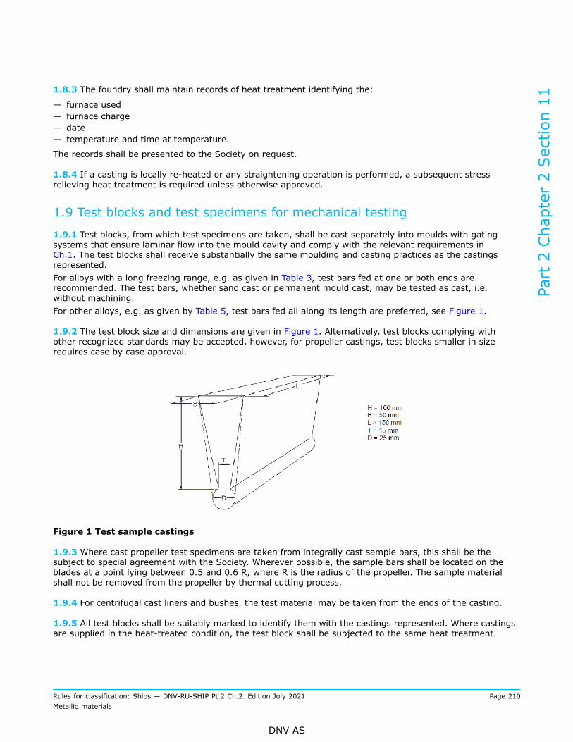
1.8.3 The foundry shall maintain records of heat treatment identifying the:
— furnace used— furnace charge— date— temperature and time at temperature.
The records shall be presented to the Society on request.
1.8.4 If a casting is locally re-heated or any straightening operation is performed, a subsequent stressrelieving heat treatment is required unless otherwise approved.
1.9 Test blocks and test specimens for mechanical testing
1.9.1 Test blocks, from which test specimens are taken, shall be cast separately into moulds with gatingsystems that ensure laminar flow into the mould cavity and comply with the relevant requirements inCh.1. The test blocks shall receive substantially the same moulding and casting practices as the castingsrepresented.For alloys with a long freezing range, e.g. as given in Table 3, test bars fed at one or both ends arerecommended. The test bars, whether sand cast or permanent mould cast, may be tested as cast, i.e.without machining.For other alloys, e.g. as given by Table 5, test bars fed all along its length are preferred, see Figure 1.
1.9.2 The test block size and dimensions are given in Figure 1. Alternatively, test blocks complying withother recognized standards may be accepted, however, for propeller castings, test blocks smaller in sizerequires case by case approval.
Figure 1 Test sample castings
1.9.3 Where cast propeller test specimens are taken from integrally cast sample bars, this shall be thesubject to special agreement with the Society. Wherever possible, the sample bars shall be located on theblades at a point lying between 0.5 and 0.6 R, where R is the radius of the propeller. The sample materialshall not be removed from the propeller by thermal cutting process.
1.9.4 For centrifugal cast liners and bushes, the test material may be taken from the ends of the casting.
1.9.5 All test blocks shall be suitably marked to identify them with the castings represented. Where castingsare supplied in the heat-treated condition, the test block shall be subjected to the same heat treatment.
Part 2 Chapter 2 Section 11
Rules for classification: Ships — DNV-RU-SHIP Pt.2 Ch.2. Edition July 2021 Page 210Metallic materials
DNV AS

1.9.6 The preparation of test specimens and the procedures used for mechanical testing shall comply withthe relevant requirements in Ch.1.
1.10 Test units and number of tests
1.10.1 Each ladle shall be regarded as a test unit. At least one set of mechanical test is required for eachtest unit.
1.10.2 In the case of multiple castings being poured from the same ladle, at least one set of mechanical testis required from the ladle representing all castings from that ladle.
1.10.3 Where castings are made from two or more ladles one set of mechanical test shall be made fromeach ladle unless the metal in the ladle originate from the same cast.
1.11 Mechanical properties
1.11.1 The mechanical properties specified in subsequent subsections refer to test specimens machined fromseparately cast test blocks and not to the castings themselves. The mechanical properties of integral-casttest material shall be specially approved.
1.11.2 If the results of the mechanical tests do not conform to the specified requirements, the re-testprocedures of Ch.1 Sec.2 [3.8] may be adopted.
1.12 Inspection
1.12.1 All finished castings shall be visually inspected on accessible surfaces. Where applicable, thisshall include the inspection of internal surfaces and bores. The surfaces shall be adequately preparedfor inspection. The surfaces shall not be hammered, peened or treated in any way which may obscurediscontinuities.
1.12.2 Castings for which certification by the Society is required shall be presented to the Society for visualinspection. The Society may require areas to be etched for the purpose of investigating weld repairs.
1.12.3 When visually inspected, castings shall have a workmanlike finish and shall be free from adheringsand, scale, cracks, hot tears or other imperfections which, due to their nature, degree or extent, willinterfere with the use of the castings or the further manufacturing processes.
1.12.4 The dimensions and the dimensional and geometrical tolerances are governed by the data specifiedin the approval drawings or order documents. These shall be submitted to the Society at the time of the test.Unless otherwise agreed, the verification of dimensions is the responsibility of the manufacturer.
1.12.5 Castings are subject to non-destructive testing where specified in subsequent sub-sections. Non-destructive testing shall be performed in accordance with the general practice of recognised standards, e.g.:
— liquid penetrant testing (PT): ISO 3452, ASTM E165.
1.12.6 For definitions relevant to PT indications the relevant parts of Sec.8 [1.12] apply.
1.12.7 Where PT is specified, the tests shall be carried out when the surface is in the final condition.Machined castings shall be tested after final machining. Where certification by the Society is required, theSociety may request to be present during PT.
Part 2 Chapter 2 Section 11
Rules for classification: Ships — DNV-RU-SHIP Pt.2 Ch.2. Edition July 2021 Page 211Metallic materials
DNV AS

1.12.8 The foundry shall maintain records of the foundry’s inspections traceable to each casting. The recordsshall be presented to the Society upon request where applicable. The foundry is also to provide the Societywith a statement confirming that non-destructive tests have been carried out with satisfactory results.
1.13 Repair
1.13.1 This paragraph gives general requirements for repair. Additional requirements are given in [2] and[3].
1.13.2 Defects may be removed by chipping, milling or grinding. Chipping or milling shall always be followedby grinding. The resulting grooves shall have a bottom radius of approximately three times the groove depthand shall be blended into the surrounding surface so as to avoid any sharp contours. Complete elimination ofthe defective material shall be verified by PT.
1.13.3 Where repair by welding is permitted, the excavations shall be suitably shaped to allow good accessfor welding. The resulting grooves shall be subsequently ground smooth and complete elimination of thedefective material shall be verified by PT.
1.13.4 All weld repairs shall be done by qualified welders using qualified procedures. For qualification ofwelding procedures for copper alloy propellers, see Ch.4 Sec.5 [13].
1.13.5 The welding consumables used shall be of a suitable composition. Welding consumables shall bestored and handled in accordance with the manufacturer's recommendations.
1.13.6 Weld repairs and adjacent material shall be ground smooth. All weld repairs are subject to non-destructive testing.
1.13.7 The foundry shall maintain records of welding, subsequent heat treatment and inspections traceableto each casting repaired. The records shall be presented to the Society on request.
1.14 Identification
1.14.1 Each casting which has been tested and inspected with satisfactory results shall be suitably identifiedby the manufacturer with the following:
— cast number or other marking which will enable the full history of the casting to be traced— the NV certificate No. where applicable and as furnished by the Society— test pressure, where applicable.
2 Castings for valves, fittings and general application
2.1 Scope
2.1.1 These requirements are supplementary to subsection [1] and apply to copper alloy castings for valves,fittings and other castings for use in vessel construction and machinery or piping systems.
Part 2 Chapter 2 Section 11
Rules for classification: Ships — DNV-RU-SHIP Pt.2 Ch.2. Edition July 2021 Page 212Metallic materials
DNV AS

2.2 Chemical composition
2.2.1 The chemical composition shall comply with the limits given in a recognised standard approved bythe Society for the application in question and where appropriate, with the limits for the principal elementsof the preferred alloys listed in Table 3. The copper alloys shall have a satisfactory resistance to sea watercorrosion, where applicable.
Table 3 Chemical composition limits for principal elements in copper alloy castings
Chemical compositionAlloy type Designation
Cu Sn Zn Pb Ni P
Typicalapplications
Phosphorbronze
Cu Sn11P
Cu Sn12
87.9 to89.5
85.9 to88.5
10.0 to11.5
11.0 to13.0
0.05 max
0.50 max
0.25 max
0.7 max
0.10max
2.0 max
0.5 to 1.0
0.60 max
Liners,bushes,valves andfittings
Gunmetal Cu Sn10 Zn2 Remainder 9.5 to 10.5 1.75 to2.75 1.5 max 1.0 max -
Liners,valves andfittings
Leadedgunmetal
Cu Sn5 Zn5 Pb5
Cu Sn7 Zn2 Pb3
Cu Sn7 Zn4 Pb7
Cu Sn6 Zn4 Pb2
83.0 to87.0
85.0 to89.0
81.0 to85.0
86.0 to90.0
4.0 to 6.0
6.0 to 8.0
6.0 to 8.0
5.5 to 6.5
4.0 to 6.0
1.5 to 3.0
2.0 to 5.0
3.0 to 5.0
4.0 to 6.0
2.5 to 3.5
5.0 to 8.0
1.0 to 2.0
2.0 max
2.0 max
2.0 max
1.0 max
0.10 max
0.10 max
0.10 max
0.05 max
Bushes,valves andfittings
Leadedbronze
Cu Sn10 Pb10
Cu Sn5 Pb9
Cu Sn7 Pb15
Cu Sn5 Pb20
78.0 to82.0
80.0 to87.0
74.0 to80.0
70.0 to78.0
9.0 to 11.0
4.0 to 6.0
6.0 to 8.0
4.0 to 6.0
2.0 max
2.0 max
2.0 max
2.0 max
8.0 to 11.0
8.0 to 10.0
13.0 to17.0
18.0 to23.0
2.0 max
2.0 max
0.5 to2.0
0.5 to2.5
0.10 max
0.10 max
0.10 max
0.10 max
Bushes
2.3 Condition of supply and heat treatment
2.3.1 The castings shall be supplied in either the as-cast condition or the heat-treated condition as specifiedin the relevant recognised standard.
2.4 Mechanical properties
2.4.1 The test blocks and test specimens for mechanical testing shall be as described in the approvedrecognised standard, see [2.2.1]. In addition subsections [1.9] to [1.11] shall apply.
Part 2 Chapter 2 Section 11
Rules for classification: Ships — DNV-RU-SHIP Pt.2 Ch.2. Edition July 2021 Page 213Metallic materials
DNV AS

2.4.2 The mechanical properties shall comply with the approved recognised standard, see [2.2.1] and whereappropriate, with the values given in Table 4.
Table 4 Mechanical properties for copper alloy castings
Proof stress Rp0.2minimum [N/mm2]
Tensile strength Rmminimum [N/mm2]
Elongation,minimum [%]Alloy type Designation
Sand Centrifugal Sand Centrifugal Sand Centrifugal
Phosphor bronzeCu Sn11 P
Cu Sn12
130
140
170
150
250
260
330
280
5
7
4
5
Gunmetal Cu Sn10 Zn2 130 130 270 250 13 5
Leaded gunmetal
Cu Sn5 Zn5 Pb5
Cu Sn7 Zn2 Pb3
Cu Sn7 Zn4 Pb7
Cu Sn6 Zn4 Pb2
90
130
120
110
110
130
120
110
200
230
230
220
250
260
260
240
13
14
15
15
13
12
12
12
Leaded bronze
Cu Sn10 Pb10
Cu Sn5 Pb9
Cu Sn7 Pb15
Cu Sn5 Pb20
80
60
80
70
110
90
90
80
180
160
170
150
220
200
200
170
8
7
8
5
6
6
7
6
2.5 Inspection
2.5.1 Pressure retaining castings shall be tested, after machining, in accordance with a recognised testingstandard to the test pressure and time required by the relevant design and construction parts of the rules. Noleaks are permitted.
2.6 Repair
2.6.1 Defective castings shall be repaired in accordance with [1.12] and as given in [2.6.2] to [2.6.5].
2.6.2 Small surface defects shall be removed by grinding to a depth of up to 10% of the section thicknessprovided the dimensional tolerances are not exceeded. Where the repair entails removal of more than 10% ofthe thickness, the defective area shall be repaired by welding.
2.6.3 Weld repairs are classified as major or minor. A weld repair is considered major when:
— the depth of the groove prepared for welding exceeds 20% of the section thickness, or— the total weld area exceeds 4% of the casting surface, or— castings have leaked on hydraulic testing.
All other weld repairs are considered minor.
2.6.4 Major weld repairs require the approval of the Society before the repair is commenced. Proposals formajor weld repairs shall be accompanied by sketches or photographs showing the extent and positions of therepairs.
2.6.5 Minor weld repairs do not require the approval of the Society before the repair is commenced but shallbe recorded on sketches showing the extent and positions of the repairs. The records shall be presented tothe Society on request.
Part 2 Chapter 2 Section 11
Rules for classification: Ships — DNV-RU-SHIP Pt.2 Ch.2. Edition July 2021 Page 214Metallic materials
DNV AS
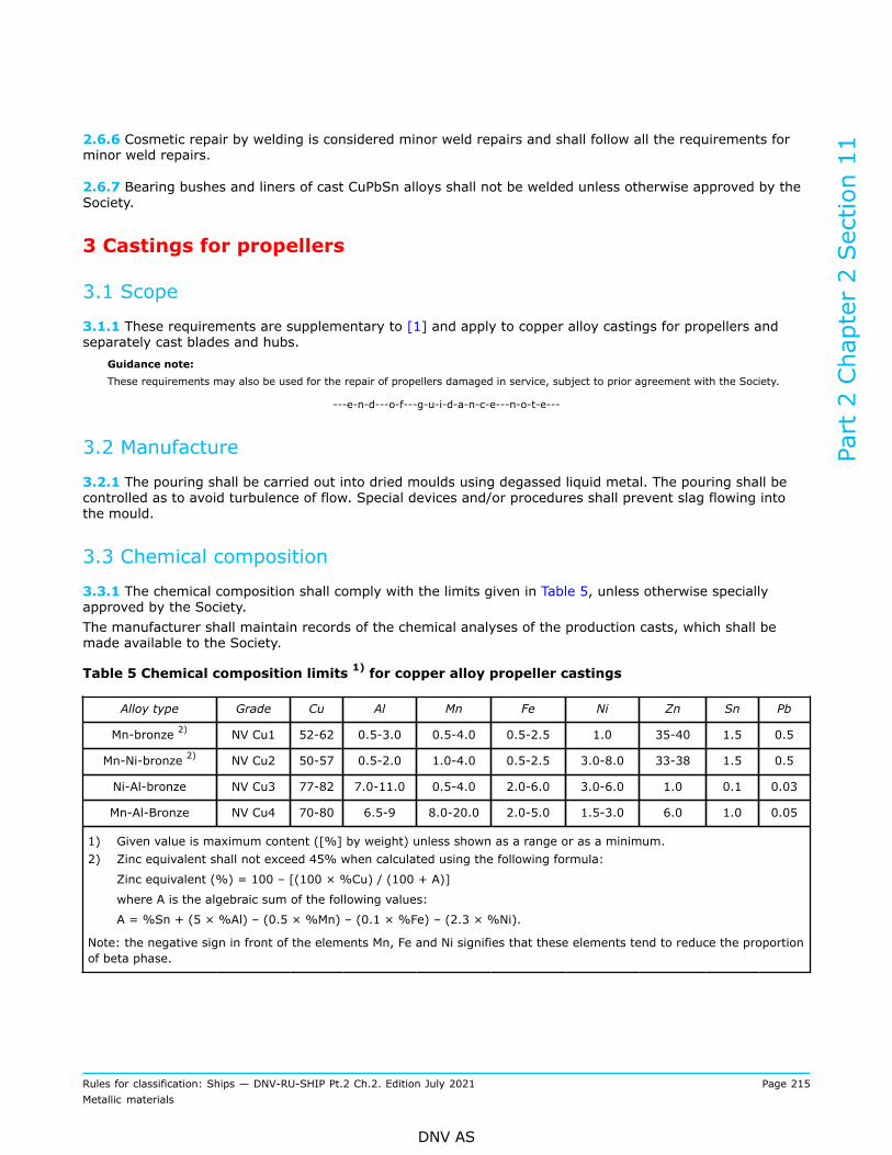
2.6.6 Cosmetic repair by welding is considered minor weld repairs and shall follow all the requirements forminor weld repairs.
2.6.7 Bearing bushes and liners of cast CuPbSn alloys shall not be welded unless otherwise approved by theSociety.
3 Castings for propellers
3.1 Scope
3.1.1 These requirements are supplementary to [1] and apply to copper alloy castings for propellers andseparately cast blades and hubs.
Guidance note:These requirements may also be used for the repair of propellers damaged in service, subject to prior agreement with the Society.
---e-n-d---o-f---g-u-i-d-a-n-c-e---n-o-t-e---
3.2 Manufacture
3.2.1 The pouring shall be carried out into dried moulds using degassed liquid metal. The pouring shall becontrolled as to avoid turbulence of flow. Special devices and/or procedures shall prevent slag flowing intothe mould.
3.3 Chemical composition
3.3.1 The chemical composition shall comply with the limits given in Table 5, unless otherwise speciallyapproved by the Society.The manufacturer shall maintain records of the chemical analyses of the production casts, which shall bemade available to the Society.
Table 5 Chemical composition limits 1) for copper alloy propeller castings
Alloy type Grade Cu Al Mn Fe Ni Zn Sn Pb
Mn-bronze 2) NV Cu1 52-62 0.5-3.0 0.5-4.0 0.5-2.5 1.0 35-40 1.5 0.5
Mn-Ni-bronze 2) NV Cu2 50-57 0.5-2.0 1.0-4.0 0.5-2.5 3.0-8.0 33-38 1.5 0.5
Ni-Al-bronze NV Cu3 77-82 7.0-11.0 0.5-4.0 2.0-6.0 3.0-6.0 1.0 0.1 0.03
Mn-Al-Bronze NV Cu4 70-80 6.5-9 8.0-20.0 2.0-5.0 1.5-3.0 6.0 1.0 0.05
1) Given value is maximum content ([%] by weight) unless shown as a range or as a minimum.2) Zinc equivalent shall not exceed 45% when calculated using the following formula:
Zinc equivalent (%) = 100 – [(100 × %Cu) / (100 + A)]
where A is the algebraic sum of the following values:
A = %Sn + (5 × %Al) – (0.5 × %Mn) – (0.1 × %Fe) – (2.3 × %Ni).
Note: the negative sign in front of the elements Mn, Fe and Ni signifies that these elements tend to reduce the proportionof beta phase.
Part 2 Chapter 2 Section 11
Rules for classification: Ships — DNV-RU-SHIP Pt.2 Ch.2. Edition July 2021 Page 215Metallic materials
DNV AS
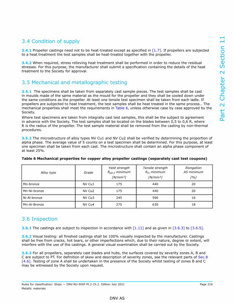
3.4 Condition of supply
3.4.1 Propeller castings need not to be heat-treated except as specified in [1.7]. If propellers are subjectedto a heat treatment the test samples shall be heat-treated together with the propeller.
3.4.2 When required, stress relieving heat treatment shall be performed in order to reduce the residualstresses. For this purpose, the manufacturer shall submit a specification containing the details of the heattreatment to the Society for approval.
3.5 Mechanical and metallographic testing
3.5.1 The specimens shall be taken from separately cast sample pieces. The test samples shall be castin moulds made of the same material as the mould for the propeller and they shall be cooled down underthe same conditions as the propeller. At least one tensile test specimen shall be taken from each ladle. Ifpropellers are subjected to heat treatment, the test samples shall be heat treated in the same process.. Themechanical properties shall meet the requirements in Table 6, unless otherwise case by case approved by theSociety.Where test specimens are taken from integrally cast test samples, this shall be the subject to agreementin advance with the Society. The test samples shall be located on the blades between 0,5 to 0,6 R, whereR is the radius of the propeller. The test sample material shall be removed from the casting by non-thermalprocedures.
3.5.2 The microstructure of alloy types NV Cu1 and NV Cu2 shall be verified by determining the proportion ofalpha phase. The average value of 5 counts on a test specimen shall be determined. For this purpose, at leastone specimen shall be taken from each cast. The microstructure shall contain an alpha phase component ofat least 25%.
Table 6 Mechanical properties for copper alloy propeller castings (separately cast test coupons)
Alloy type GradeYield strengthRp0.2 minimum
[N/mm²]
Tensile strengthRm minimum
[N/mm²]
ElongationA5 minimum
[%]
Mn-bronze NV Cu1 175 440 20
Mn-Ni-bronze NV Cu2 175 440 20
Ni-Al-bronze NV Cu3 245 590 16
Mn-Al-Bronze NV Cu4 275 630 18
3.6 Inspection
3.6.1 The castings are subject to inspection in accordance with [1.11] and as given in [3.6.3] to [3.6.5].
3.6.2 Visual testing: all finished castings shall be 100% visually inspected by the manufacturer. Castingsshall be free from cracks, hot tears, or other imperfections which, due to their nature, degree or extent, willinterfere with the use of the castings. A general visual examination shall be carried out by the Society.
3.6.3 For all propellers, separately cast blades and hubs, the surfaces covered by severity zones A, B andC are subject to PT. For definition of skew and description of severity zones, see the relevant parts of Sec.8[4.6]. Testing of zone A shall be undertaken in the presence of the Society whilst testing of zones B and Cmay be witnessed by the Society upon request.
Part 2 Chapter 2 Section 11
Rules for classification: Ships — DNV-RU-SHIP Pt.2 Ch.2. Edition July 2021 Page 216Metallic materials
DNV AS

3.6.4 For the purpose of evaluating PT indications, the surface shall be divided into reference areas of 100cm2, which may be square or rectangular with the major dimension not exceeding 250 mm. The area shall betaken in the most unfavourable location relative to the indication being evaluated.
3.6.5 The indications detected shall, with respect to their size and number, not exceed the values given inCh.4 Sec.5 Table 22. Weld repairs are, independent of their location, always to be assessed according to therequirements for zone A. The zone A requirements are applicable for the welded areas after final machiningand/or final grinding.
Guidance note:Radiographic test (RT); the absorption of the X-rays and gamma-rays is stronger in copper-based alloys than in steel. For propellerbronzes, 300 kV X-rays can normally be used up to 50 mm and Co60 gamma-rays up to 160 mm thickness. Due to the limitedthicknesses that can be radiographed as well as for other practical reasons radiography is generally not a realistic method forchecking of subsurface defects in the thicker parts of large propellers.Ultrasonic test (UT); as a general rule, ultrasonic testing of NV Cu1 and NV Cu2 is not feasible due to the high damping capacityof these materials. For NV Cu3 and NV Cu4, ultrasonic inspection of subsurface defects is possible. If UT is applied, the procedureshould be qualified.
---e-n-d---o-f---g-u-i-d-a-n-c-e---n-o-t-e---
3.6.6 Radiographic and ultrasonic testing: when required by the Society or when deemed necessary by themanufacturer, further non-destructive testing, e.g. radiographic and/or ultrasonic testing, shall be carriedout. The acceptance criteria or applied quality levels shall be agreed between the manufacturer and theSociety in accordance with a recognized standard.
Note:Due to the attenuating effect of ultrasound within cast copper alloys, ultrasonic testing may not be practical in some cases,depending on the shape/type/thickness, and grain-growth direction of the casting.In such cases, effective ultrasound penetration into the casting should be practically demonstrated on the item. This wouldnormally be determined by way of back-wall reflection, and/or target features within the casting.
---e-n-d---o-f---n-o-t-e---
3.6.7 Minor casting defects which may still be visible after machining such as small sand and slag inclusions,small cold shuts and scabs shall be trimmed off by the manufacturer, see [3.7].
3.6.8 Casting defects which would exclude the casting from proper application in service, e.g. major non-metallic inclusions, shrinkage cavities, blow holes and cracks, are not permitted. The defects shall beremoved by one of the methods given in accordance with [3.7] and repaired within the limits and restrictionsfor the applicable severity zone.
3.7 Repair
3.7.1 Defective castings shall be repaired in accordance with [1.13] and as given in [3.7.2] to [3.7.10].
3.7.2 The repairs shall be carried out by mechanical means, e.g. by grinding or milling. Weld repairs shall beundertaken only when they are considered to be necessary.
3.7.3 Welding shall generally be carried out in flat position (down-hand, 1G/PA). Where this cannot be done,gas metal arc welding (GMAW) or gas tungsten arc welding (GTAW) should be carried out.
3.7.4 Weld repairs in zone A and zone B require the approval of the Society before the repair is commenced.Proposals for weld repairs shall be accompanied by sketches or photographs showing the extent and positionsof the repairs. Welding of areas less than 5 cm2 shall be avoided.
3.7.5 Grinding in severity zone A may be carried out to an extent that maintains the blade thickness. Ifblade thickness after grinding is below specified under-thickness tolerance, the blade is either rejected, or
Part 2 Chapter 2 Section 11
Rules for classification: Ships — DNV-RU-SHIP Pt.2 Ch.2. Edition July 2021 Page 217Metallic materials
DNV AS
the grinding repair may be evaluated and possibly case-by-case approved by the Society. The balance testshall be repeated. Repair welding is not permitted in severity zone A and will only be allowed after specialconsideration by the Society.In some cases, the propeller designer may submit technical documentation to propose a modified zone Abased on detailed hydrodynamic load and stress analysis for consideration by the Society.
3.7.6 Defects in severity zone B that are not deeper than t/40 mm (t is the minimum local thicknessaccording to the rules) or 2 mm, whichever is greatest, may be removed by grinding. Those defects that aredeeper may be repaired by welding.
3.7.7 Repair welding is permitted in severity zone C.
3.7.8 Requirements for the welding workshop are given in Ch.4. Proof of compliance shall be furnished to thesatisfaction of the Society prior to welding. All welding work shall be carried out preferably inside the shopfree from draughts and influence of the weather.
3.7.9 Repair welding: the foundry shall maintain records of inspections, welding, and any subsequent heattreatment, traceable to each casting.Before welding is started, a detailed repair procedure shall be submitted including the extent and location ofthe repair, the WPS, see Ch.4 Sec.5 [13], weld preparation, welding parameters, filler metals, preheating,post weld heat treatment and subsequent inspection procedures for approval. Recommendations for weldingare given in Ch.4 Sec.5 Table 20.Arc welding shall be used for all types of welding repair on cast copper alloy propellers. Arc welding withcovered electrodes and gas-shielded metal arc process (GMAW) shall be applied.
Guidance note:Argon-shielded tungsten welding (GTAW) should be used with care due to the higher specific heat input of this process.Recommended filler metals, preheating and stress relieving temperatures are listed in Ch.4 Sec.5 Table 20.
---e-n-d---o-f---g-u-i-d-a-n-c-e---n-o-t-e---
Defects to be repaired by welding shall be grounded to sound material. The welding grooves shall beprepared in a manner which will allow fusion of the groove bottom. The resulting ground areas shallbe examined, in the presence of the Society, by liquid penetrant testing in order to verify the completeelimination of defective material.
3.7.10 With the exception of NiAl-bronze all weld repairs shall be stress relief heat-treated, in order to avoidstress corrosion cracking. However, stress relief heat treatment of alloy NV Cu3 propeller castings may berequired after major repairs in zone B (and specially approved welding in zone A) or if a welding consumablesusceptible to stress corrosion cracking is used. In such cases the propeller shall be either stress relief heattreated in the temperature 450°C to 500°C or annealed in the temperature range 650°C to 800°C, dependingon the extent of repair, see Ch.4 Sec.5 Table 20. The temperatures for the heat treatment are given inCh.4 Sec.5 Table 20. The soaking times for stress relief heat treatment of copper alloy propellers shall be inaccordance with Ch.4 Sec.5 Table 21. The cooling rate shall not exceed 50oC/h until a temperature of 200oCis reached.
3.7.11 If repairs have been made either by grinding, straightening, or by welding, the repaired areas shalladditionally be subjected to the liquid penetrant testing independent of their location and/or severity zone.
3.8 Straightening
3.8.1 Application of load: for hot and cold straightening purposes, only static loading shall be used.
3.8.2 Hot straightening: weld repaired areas may be subject to hot straightening provided it isdemonstrated that weld properties are not impaired by the hot straightening operations.
Part 2 Chapter 2 Section 11
Rules for classification: Ships — DNV-RU-SHIP Pt.2 Ch.2. Edition July 2021 Page 218Metallic materials
DNV AS

Straightening of a bent propeller blade or a pitch modification should be carried out after heating the bentregion and approximately 500 mm wide zones on either side to the suggested temperature range given inCh.4 Sec.5 Table 20.The heating should be slow and uniform and the concentrated flames such as oxy-acetylene and oxy-propaneshould not be used. Sufficient time should be allowed for the temperature to become uniform through the fullthickness of the blade section. The temperature shall be maintained within the suggested range throughoutthe straightening operation. A thermocouple instrument or temperature indicating crayons should be used formeasuring the temperature.
3.8.3 Cold straightening: cold straightening should be used for minor repairs of tips and edges only. Coldstraightening on NV Cu1, NV Cu2, and NV Cu4 casting should always be followed by a stress relieving heattreatment, see Ch.4 Sec.5 Table 20.
3.9 Identification
3.9.1 Castings shall be identified in accordance with [1.14] and with the following additional particulars:
— grade of cast material of corresponding abbreviated designation— manufacturer's mark— number of the Society's test certificate— ice class symbol, where applicable— skew angle for high skew propellers— date of final inspection.
3.10 Welding procedure qualification
3.10.1 Requirements for welding procedure qualification test are given in Ch.4 Sec.5 [13].
Part 2 Chapter 2 Section 11
Rules for classification: Ships — DNV-RU-SHIP Pt.2 Ch.2. Edition July 2021 Page 219Metallic materials
DNV AS

SECTION 12 NON-FERROUS TUBES
1 General requirements
1.1 Scope
1.1.1 This section specified requirements for copper and copper alloy tubes and fittings to be used inpressurized lines and for condenser and heat exchangers, and for titanium and titanium alloy tubes to beused in shipboard systems.
1.2 Required compliance documentation
1.2.1 General compliance document requirements are given in Sec.1 [3.1].
1.2.2 The manufacturer shall provide the type of compliance document required in the relevant constructionrules giving the following particulars for each test unit which has been accepted:
a) purchaser's name, order number and vessel identification, where knownb) manufacturer's namec) description of tubes/fittings and material qualityd) identification marking of tubes/fittingse) cast number and chemical compositionf) results of mechanical tests and, where applicable, technological testsg) test pressure or results of eddy current testsh) results of any supplementary and additional test requirements specified.
1.2.3 Where the copper alloys are not cast in the same works in which they are made into finished or semi-finished products, the works shall be approved by the Society, and the surveyor shall be given a works(W) material certificate validated by the smelting plant which indicates charge numbers and chemicalcomposition.
1.3 Documentation requirements
1.3.1 General documentation requirements are given in Sec.1 [3.2]. Additional product specificdocumentation requirements are given in Table 1.
Table 1 Documentation requirements – products required to be certified
Object Documentation type Additional description Info 1)
Copper material M010 – Material specification, metals When material other than those specifiedin this rule section is proposed FI
Titanium material M010 – Material specification, metals When material other than those specifiedin this rule section is proposed FI
1) FI = for information.
1.3.2 For general requirements to documentation including definitions, see DNV-CG-0550.
Part 2 Chapter 2 Section 12
Rules for classification: Ships — DNV-RU-SHIP Pt.2 Ch.2. Edition July 2021 Page 220Metallic materials
DNV AS
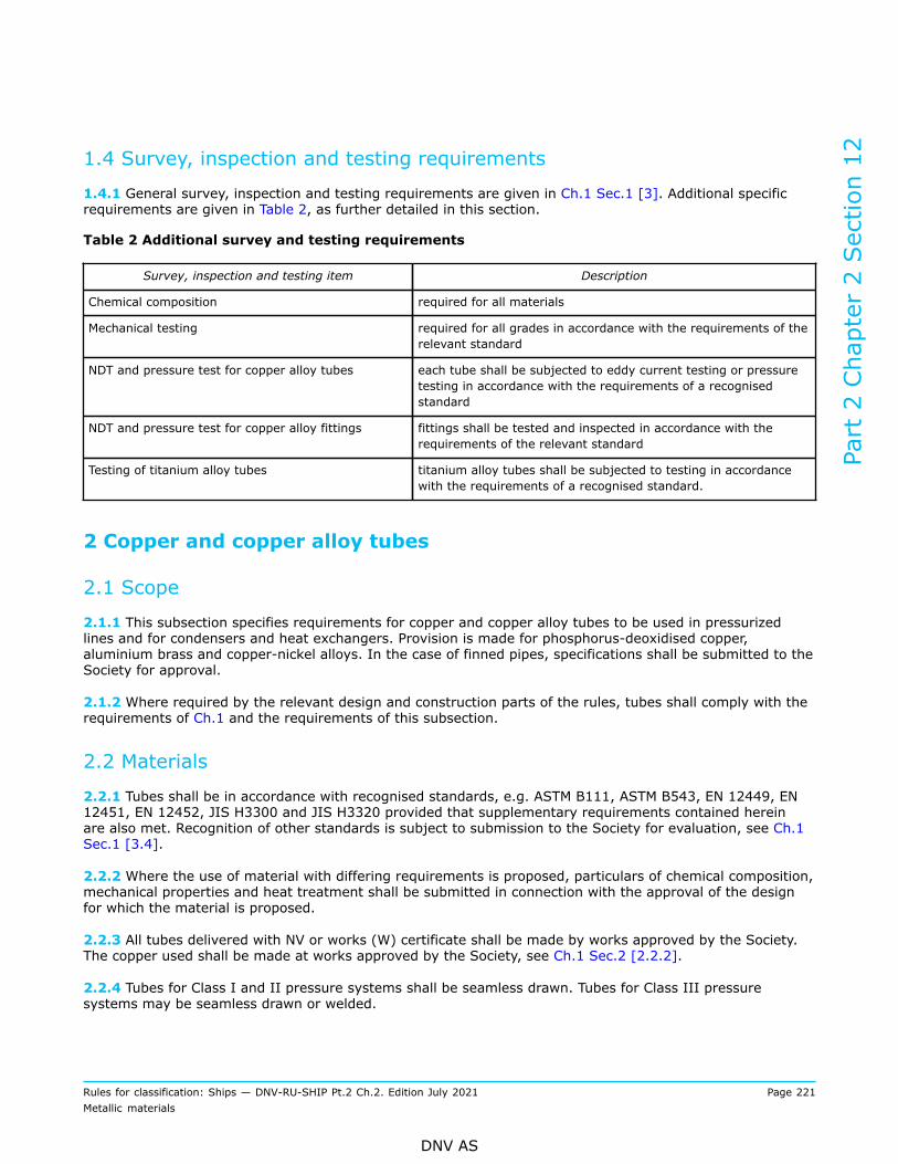
1.4 Survey, inspection and testing requirements
1.4.1 General survey, inspection and testing requirements are given in Ch.1 Sec.1 [3]. Additional specificrequirements are given in Table 2, as further detailed in this section.
Table 2 Additional survey and testing requirements
Survey, inspection and testing item Description
Chemical composition required for all materials
Mechanical testing required for all grades in accordance with the requirements of therelevant standard
NDT and pressure test for copper alloy tubes each tube shall be subjected to eddy current testing or pressuretesting in accordance with the requirements of a recognisedstandard
NDT and pressure test for copper alloy fittings fittings shall be tested and inspected in accordance with therequirements of the relevant standard
Testing of titanium alloy tubes titanium alloy tubes shall be subjected to testing in accordancewith the requirements of a recognised standard.
2 Copper and copper alloy tubes
2.1 Scope
2.1.1 This subsection specifies requirements for copper and copper alloy tubes to be used in pressurizedlines and for condensers and heat exchangers. Provision is made for phosphorus-deoxidised copper,aluminium brass and copper-nickel alloys. In the case of finned pipes, specifications shall be submitted to theSociety for approval.
2.1.2 Where required by the relevant design and construction parts of the rules, tubes shall comply with therequirements of Ch.1 and the requirements of this subsection.
2.2 Materials
2.2.1 Tubes shall be in accordance with recognised standards, e.g. ASTM B111, ASTM B543, EN 12449, EN12451, EN 12452, JIS H3300 and JIS H3320 provided that supplementary requirements contained hereinare also met. Recognition of other standards is subject to submission to the Society for evaluation, see Ch.1Sec.1 [3.4].
2.2.2 Where the use of material with differing requirements is proposed, particulars of chemical composition,mechanical properties and heat treatment shall be submitted in connection with the approval of the designfor which the material is proposed.
2.2.3 All tubes delivered with NV or works (W) certificate shall be made by works approved by the Society.The copper used shall be made at works approved by the Society, see Ch.1 Sec.2 [2.2.2].
2.2.4 Tubes for Class I and II pressure systems shall be seamless drawn. Tubes for Class III pressuresystems may be seamless drawn or welded.
Part 2 Chapter 2 Section 12
Rules for classification: Ships — DNV-RU-SHIP Pt.2 Ch.2. Edition July 2021 Page 221Metallic materials
DNV AS

2.2.5 For welded tubes, the characteristics of these and the method of manufacture employed shall be madeknown to the Society. The Society reserves the right to demand a procedure approval test in these cases.
2.3 Chemical composition
2.3.1 The chemical composition shall comply with the requirements of a recognised standard and with thelimits for principal elements given in Table 3.
2.4 Condition of supply and heat treatment
2.4.1 Copper tubes shall be supplied in the annealed or half-hard condition.
2.4.2 Copper alloy tubes shall be supplied in the annealed condition.
2.4.3 Tubes made of copper zinc alloys shall be free from stresses liable to cause stress cracks.
2.4.4 With the exception of tubes made of phosphorus-deoxidised copper in condition hard, all pipes shallbe capable of being cold formed with the degrees of deformation customary in workshop practice, e.g. bybending and expansion.
Table 3 Chemical composition limits 1) for principal elements in copper and copper alloy tubes
Designation Cu As P Pb Fe Zn Ni Al Mn
Phosphorus-deoxidisedcopper
Minimum99.9 2) - 0.015
to 0.040 - - - - - -
Aluminium brass 76.0 to79.0
0.02to 0.06 - 0.07 0.06 Remainder - 1.8
to 2.5 -
Copper-Nickel 90-10 3) Remainder - - - 1.0 to2.0 - 9.0 to
11.0 - 0.5to 1.0
Copper-Nickel 70-30 3) Remainder - - - 0.40to 1.0 - 29.0
to 33.0 - 0.5to 1.5
1) Given value is maximum content ([%] by weight) unless shown as a range or as a minimum.2) Including silver.3) When the product is intended for subsequent welding, the following maximum limits apply: zinc 0.50%, lead 0.02%,
phosphorus 0.02%, sulphur 0.02% and carbon 0.05%.
2.5 Mechanical testing
2.5.1 Tubes shall be sampled and subjected to testing in accordance with the requirements of a recognisedstandard.
2.5.2 The mechanical properties shall comply with the requirements of the applied standard (see [2.2]) andwhere relevant, with the minimum values given in Table 4.
2.5.3 Further requirements with respect to testing, retesting, identification and certification are outlined inCh.1.
Part 2 Chapter 2 Section 12
Rules for classification: Ships — DNV-RU-SHIP Pt.2 Ch.2. Edition July 2021 Page 222Metallic materials
DNV AS
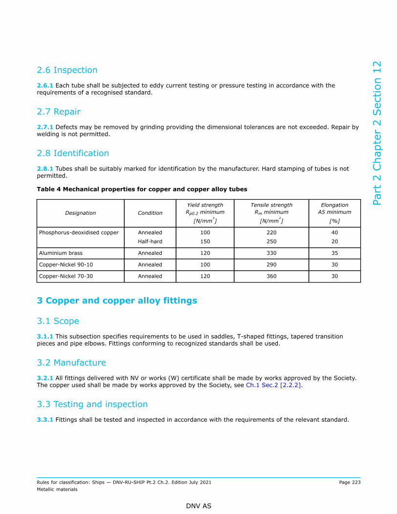
2.6 Inspection
2.6.1 Each tube shall be subjected to eddy current testing or pressure testing in accordance with therequirements of a recognised standard.
2.7 Repair
2.7.1 Defects may be removed by grinding providing the dimensional tolerances are not exceeded. Repair bywelding is not permitted.
2.8 Identification
2.8.1 Tubes shall be suitably marked for identification by the manufacturer. Hard stamping of tubes is notpermitted.
Table 4 Mechanical properties for copper and copper alloy tubes
Designation ConditionYield strengthRp0.2 minimum
[N/mm²]
Tensile strengthRm minimum
[N/mm²]
ElongationA5 minimum
[%]
Phosphorus-deoxidised copper Annealed
Half-hard
100
150
220
250
40
20
Aluminium brass Annealed 120 330 35
Copper-Nickel 90-10 Annealed 100 290 30
Copper-Nickel 70-30 Annealed 120 360 30
3 Copper and copper alloy fittings
3.1 Scope
3.1.1 This subsection specifies requirements to be used in saddles, T-shaped fittings, tapered transitionpieces and pipe elbows. Fittings conforming to recognized standards shall be used.
3.2 Manufacture
3.2.1 All fittings delivered with NV or works (W) certificate shall be made by works approved by the Society.The copper used shall be made by works approved by the Society, see Ch.1 Sec.2 [2.2.2].
3.3 Testing and inspection
3.3.1 Fittings shall be tested and inspected in accordance with the requirements of the relevant standard.
Part 2 Chapter 2 Section 12
Rules for classification: Ships — DNV-RU-SHIP Pt.2 Ch.2. Edition July 2021 Page 223Metallic materials
DNV AS

3.4 Identification
3.4.1 Fittings shall be suitably marked for identification by the manufacturer. Hard stamping of tubes is notpermitted.
4 Titanium and titanium alloy tubes and fittings
4.1 Scope
4.1.1 This subsection specifies requirements for titanium and titanium alloy tubes and fittings to be usedin shipboard systems. Provision is made for grade 1 and grade 2 unalloyed titanium and grade 9 titaniumalloys.
4.1.2 Tubes shall be in accordance with recognised standards, e.g. ASTM B338, ASTM B861 and ASTM B862provided that supplementary requirements contained herein also are met. Recognition of other standards issubject to submission to the Society for evaluation, see Ch.1 Sec.1 [3.4].
4.1.3 Fittings shall be in accordance with recognised standards.
4.1.4 Where required by the relevant design and construction parts of the rules, tubes and fittings shallcomply with the requirements of Ch.1 and the requirements of this subsection.
4.1.5 Where the use of material with differing requirements is proposed, particulars of chemical composition,mechanical properties and heat treatment shall be submitted in connection with the approval of the designfor which the material is proposed, see also Ch.1 Sec.1 [3.4].
4.2 Manufacture
4.2.1 All tubes and fittings shall be made at works approved by the Society.
4.2.2 Tubes for class I and II pressure systems shall be seamless. Tubes for class III pressure systems maybe seamless or welded.
Part 2 Chapter 2 Section 12
Rules for classification: Ships — DNV-RU-SHIP Pt.2 Ch.2. Edition July 2021 Page 224Metallic materials
DNV AS
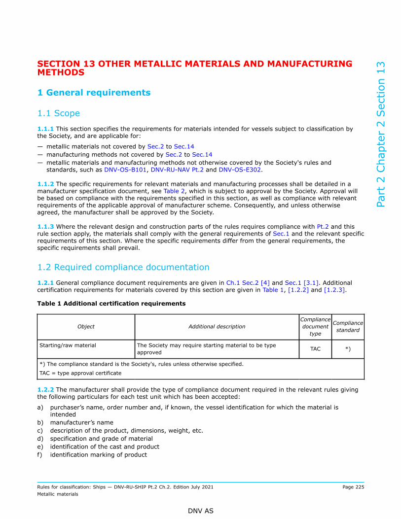
SECTION 13 OTHER METALLIC MATERIALS AND MANUFACTURINGMETHODS
1 General requirements
1.1 Scope
1.1.1 This section specifies the requirements for materials intended for vessels subject to classification bythe Society, and are applicable for:
— metallic materials not covered by Sec.2 to Sec.14— manufacturing methods not covered by Sec.2 to Sec.14— metallic materials and manufacturing methods not otherwise covered by the Society's rules andstandards, such as DNV-OS-B101, DNV-RU-NAV Pt.2 and DNV-OS-E302.
1.1.2 The specific requirements for relevant materials and manufacturing processes shall be detailed in amanufacturer specification document, see Table 2, which is subject to approval by the Society. Approval willbe based on compliance with the requirements specified in this section, as well as compliance with relevantrequirements of the applicable approval of manufacturer scheme. Consequently, and unless otherwiseagreed, the manufacturer shall be approved by the Society.
1.1.3 Where the relevant design and construction parts of the rules requires compliance with Pt.2 and thisrule section apply, the materials shall comply with the general requirements of Sec.1 and the relevant specificrequirements of this section. Where the specific requirements differ from the general requirements, thespecific requirements shall prevail.
1.2 Required compliance documentation
1.2.1 General compliance document requirements are given in Ch.1 Sec.2 [4] and Sec.1 [3.1]. Additionalcertification requirements for materials covered by this section are given in Table 1, [1.2.2] and [1.2.3].
Table 1 Additional certification requirements
Object Additional descriptionCompliancedocumenttype
Compliancestandard
Starting/raw material The Society may require starting material to be typeapproved TAC *)
*) The compliance standard is the Society's, rules unless otherwise specified.
TAC = type approval certificate
1.2.2 The manufacturer shall provide the type of compliance document required in the relevant rules givingthe following particulars for each test unit which has been accepted:
a) purchaser’s name, order number and, if known, the vessel identification for which the material isintended
b) manufacturer’s namec) description of the product, dimensions, weight, etc.d) specification and grade of materiale) identification of the cast and productf) identification marking of product
Part 2 Chapter 2 Section 13
Rules for classification: Ships — DNV-RU-SHIP Pt.2 Ch.2. Edition July 2021 Page 225Metallic materials
DNV AS

g) manufacturing processh) chemical compositioni) results of mechanical tests, including traceable test identificationj) results of corrosion tests where relevantk) condition of supply, e.g. heat treatment process, surface quality, finishing, coatingl) results of inspections and NDTm) results of all relevant tests specified by the referred specification/standardn) results of any supplementary and additional test.
1.2.3 The manufacturer shall in writing confirm compliance with the approved manufacturer specification andrelevant requirements before the compliance document is endorsed by the Society.
1.3 Documentation requirements
1.3.1 General documentation requirements are given in Sec.1 [3.2]. Additional manufacturer specificdocumentation requirements are given in Table 2.
Table 2 Qualification documentation manufacturer
Item Documentation type Additional description
Metallic materials Manufacturer specification The specific requirements for relevant materialsand manufacturing processes shall be detailedConsequently, and unless otherwise agreed themanufacturer shall be approved by the Society.
1.4 Survey, inspection and testing requirements
1.4.1 General survey, inspection and testing requirements are given in Ch.1 Sec.1 [3.3]. Additional specificrequirements are given in given in Table 3 and in the approved manufacturer specification.
Table 3 Additional survey and testing requirements
Survey, inspection and testing item Description
Surface inspection and verification of dimensions The manufacturer shall verify that the dimensions and tolerancesare complying with the approved manufacturer specification
See [1.12.2]
Chemical composition testing required for all metallic materials
Mechanical testing required for all grades covered by this section unless otherwisespecified, and witnessed by the Society for compliance documenttype MC, unless otherwise agreed
Other tests required as specified in the approved manufacturer specification
1.5 Grading system
1.5.1 The materials concerned shall be given a grade name according to the approved manufacturerspecification.
Part 2 Chapter 2 Section 13
Rules for classification: Ships — DNV-RU-SHIP Pt.2 Ch.2. Edition July 2021 Page 226Metallic materials
DNV AS
1.6 Manufacture
1.6.1 Materials manufactured in accordance with this section shall be made at works approved by theSociety, see Ch.1 Sec.2 [2.2.2], and according to an approved manufacturer specification. See also DNV-CP-0346.
1.6.2 All materials delivered with compliance document MC or MD, see Ch.1 Sec.2 [4.2], shall be made atworks approved by the Society for the type, grade, and dimensions of material being supplied and for therelevant manufacturing process and delivery condition, see Ch.1 Sec.2 [2.2.2].
1.6.3 The Society may require starting material to be type approved (TA) or supplied by works approved bythe Society.
1.6.4 Conditions of supply shall be in accordance with the approved manufacturer specification.
1.6.5 It is the manufacturer’s responsibility to ensure that effective manufacture and process controls andwhere relevant, qualified or approved processes, are implemented and adhered to in production.
1.7 Chemical composition
1.7.1 The chemical composition of each product shall be determined and shall be within the limits of theapproved manufacturer specification.
1.7.2 The composition shall be determined at a process stage where it will be representative of each productin a test unit. E.g. cast analysis or product analysis of the starting material, or representative productanalysis.
1.7.3 Elements designated as residual elements in the individual specifications shall not be intentionallyadded to the steel. The content of such elements shall be documented.
1.7.4 The manufacturer shall adopt adequate control to prevent accumulation of harmful elements in theproduct. This is particularly relevant for manufacturing processes where recycled scrap is used as rawmaterial, and where the ore may contain high levels of harmful elements.
1.7.5 When required, the carbon equivalent value (Ceq, Pcm or CET) shall be calculated. For further detailsand formulas, see Ch.1 Sec.2 [3.3].
1.7.6 The manufacturer's declared analysis may be accepted subject to random checks on request by theSociety.
1.8 Condition of supply and heat treatment
1.8.1 Conditions of supply and heat treatment shall be in accordance with the requirements given in theapproved manufacturer specification.
1.9 Test material and test specimens for mechanical testing
1.9.1 Test material shall be representative of the sample product and, where appropriate, shall not beseparated from the sample product until heat treatment has been completed. Test material or test specimensshall not be separately heat-treated unless otherwise approved.
Part 2 Chapter 2 Section 13
Rules for classification: Ships — DNV-RU-SHIP Pt.2 Ch.2. Edition July 2021 Page 227Metallic materials
DNV AS

1.9.2 The size, thickness location and preparation of test specimens and the procedures used for mechanicaltesting shall in general comply with the relevant requirements of Ch.1 Sec.3, unless specified otherwise inthe approved manufacturer specification.
1.9.3 Test material shall be suitably marked to identify the relation with the products represented.
1.10 Test units and number of tests
1.10.1 Depending on product and grade, provision is made in the approved manufacturer specification fortesting of individual pieces or for batch testing. Where batch testing is permitted, a test unit shall consist ofmaterials of the same product form, from the same cast, in the same condition of supply, and with a totalmass not exceeding limits given in the approved manufacturer specification.
1.10.2 At least one set of relevant mechanical and corrosion tests is required for each test unit, unlessotherwise specified in the approved manufacturer specification.
1.11 Mechanical properties
1.11.1 The material shall comply with the mechanical properties specified in the approved manufacturerspecification.
1.11.2 If the results do not comply with the specified requirements, the re-test procedures in Ch.1 Sec.2[3.8] may be adopted. Where the products are submitted to heat treatment or re-heat treatment, all thetests previously performed shall be repeated and the results shall comply with the specified requirements.
1.12 Inspection and tolerances
1.12.1 Surface inspection and verification of dimensions including shape and straightness are theresponsibility of the manufacturer. Acceptance by the Society of material later found to be defective shall notabsolve the manufacturer from this responsibility.
1.12.2 Products shall be subjected to a thorough, visual inspection by the manufacturer to ensure freedomfrom defects and harmful imperfections, and have a workmanlike finish consistent with the method ofmanufacture and the approved manufacturer specification, and shall be free from internal and surface defectsprejudicial to the use of the material for the intended application.
1.12.3 The dimensional tolerances shall be according to the approved manufacturer specification.
1.12.4 The non-destructive testing (NDT) shall be according to the approved manufacturer specification.
1.13 Repair
1.13.1 Surface defects may be removed by localized grinding followed by proper NDT to prove completeelimination of the defects, provided that the remaining dimensions are within the dimensional tolerances ofthe product in question.
1.13.2 Repair by other methods, including welding, is not permitted unless qualified and specified in theapproved manufacturer specification.
1.13.3 The manufacturer shall maintain records of repairs, subsequent heat treatment and inspectionstraceable to each product repaired. The records shall be presented to the Society on request.
Part 2 Chapter 2 Section 13
Rules for classification: Ships — DNV-RU-SHIP Pt.2 Ch.2. Edition July 2021 Page 228Metallic materials
DNV AS

1.14 Identification
1.14.1 The finished product shall be clearly marked by the manufacturer in at least one place with the detailsspecified in Ch.1 Sec.2 [4.1.3], unless specified otherwise in the approved manufacturer specification.
2 Material grades specified to a recognized standard
2.1 Scope
2.1.1 These requirements are supplementary to [1] and apply to material grades specified according torecognized standards, for the same or equivalent application, and where a corresponding manufacturingmethod is listed in Sec.2 to Sec.14, e.g. casting, forging, hot or cold rolling, extrusion and additivemanufacturing.
Guidance note:Some examples are given as follows:
— Titanium strips, sheets, plates to ASTM B265, JIS H4600, DIN 17860.
— Wrought copper alloy plates to EN 1653, ASTM B171 or GB/T 5231.
— Nickel base alloy plates to DIN 17750.
— Nickel base alloy pipes to ASTM B757.
— Superaustenitic plates to EN 10088-2.
— Nickel base alloy castings to proprietary specification.
— Aluminium alloy forgings to JIS H4140.
— Vermicular graphite cast iron to EN 16079.
— Malleable cast iron to EN 1562.
---e-n-d---o-f---g-u-i-d-a-n-c-e---n-o-t-e---
2.1.2 Acceptance will be based on the manufacturers risk evaluation [2.2.2], material specification [2.3.1],gap analysis [2.3.2] and qualification as described in [2.3.3].
2.2 Initial qualification and establishment of the manufacturer specification2.2.1 GeneralThe initial qualification and approval of the manufacturer specification is typically done in combination withthe manufacturer approval process, see [1.6.1].The manufacturer shall prepare a risk evaluation and manufacturer specification, including a materialspecification and a gap analysis as described in [2.3.1] to [2.3.2] and submit for approval by the Society.
2.2.2 Risk evaluationThe manufacturer shall provide a risk evaluation for the material and corresponding manufacturing process,for the given application and intended environment; compared to the corresponding materials listed in Sec.2to Sec.14, related to:
— manufactured quality (surface properties, internal quality, homogeneity in quality and properties, etc.)— typical failure modes (fatigue, brittle fracture, corrosion, environmental cracking, creep, erosion,cavitation, wear, etc.)
Where there are limited documented knowledge available for the material grade with respect to the intendedapplication, a technology qualification in accordance with DNV-RP-A203 may be required. Provided therelevant knowledge is available, but there are concerns for some specific properties or failure modes, thematerial may be further qualified through qualification testing as indicated in [2.3.3].
Part 2 Chapter 2 Section 13
Rules for classification: Ships — DNV-RU-SHIP Pt.2 Ch.2. Edition July 2021 Page 229Metallic materials
DNV AS

2.3 Manufacturer specification2.3.1 Material specificationThe manufacturer shall prepare a specification identifying the applicable requirements as follows:
— applicable international or national standard— material grade and delivery condition— additional requirements and options as relevant— intended application and relevant requirements given by the applicable design rules (Pt.3 to Pt.6)— corresponding requirements given for same manufacturing process, and for similar applications, see Sec.2to Sec.14
— scope and extent of testing for regular production control and product certification.
2.3.2 Gap analysisThe manufacturer shall prepare a gap analysis identifying the main differences between the requirements ofthe selected standard and the corresponding requirements of the Society rules for a comparable product, atleast considering the following:
— manufacturing process, including in-process control measures and process control parameters, controlranges and acceptance criteria
— manufacturing equipment, including maintenance and calibration requirements— chemical composition and testing— heat treatment/delivery condition— mechanical properties and testing (e.g. specified minimum yield strength, tensile strength, elongation,reduction of area, and impact toughness properties)
— high temperature and low temperature mechanical properties and testing (where relevant)— fracture toughness properties and testing (where relevant)— fatigue properties and testing (where relevant)— creep resistance and testing (where relevant)— corrosion resistance and testing (where relevant)— formability and testing (e.g. cold forming, strain age properties, where relevant)— weldability or joinability and testing of these (where relevant)— test unit size— test specimen sampling (e.g. integral, sacrificial, thickness position)— surface quality and properties, including testing and acceptance criteria— internal quality, including testing and acceptance criteria for internal defects— repair requirements— non-destructive testing (including NDT, pressure test, leak tightness test, load test, etc.)— dimensional tolerances including extent of testing.
2.3.3 Qualification testingThe material shall be qualified through testing. The manufacturer shall propose a test scope based on the:
— manufacturer's material specification, see [2.3.1]— gap analysis, see [2.3.2]— requirements given by the applicable material standard(s)— DNV-CP-0346 and the corresponding approval of manufacturer programmes for the manufacturingmethod in question (e.g. DNV-CP-0244 for rolled austenitic and ferritic austenitic stainless steels)
— risks identified in [2.2.2]— the qualification testing shall document the properties relevant for the application.
The test scope shall be agreed with the Society, and testing shall be witnessed by the Society unlessotherwise agreed.
Part 2 Chapter 2 Section 13
Rules for classification: Ships — DNV-RU-SHIP Pt.2 Ch.2. Edition July 2021 Page 230Metallic materials
DNV AS
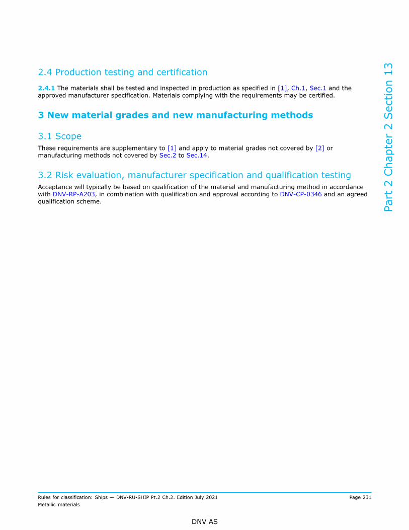
2.4 Production testing and certification
2.4.1 The materials shall be tested and inspected in production as specified in [1], Ch.1, Sec.1 and theapproved manufacturer specification. Materials complying with the requirements may be certified.
3 New material grades and new manufacturing methods
3.1 ScopeThese requirements are supplementary to [1] and apply to material grades not covered by [2] ormanufacturing methods not covered by Sec.2 to Sec.14.
3.2 Risk evaluation, manufacturer specification and qualification testingAcceptance will typically be based on qualification of the material and manufacturing method in accordancewith DNV-RP-A203, in combination with qualification and approval according to DNV-CP-0346 and an agreedqualification scheme.
Part 2 Chapter 2 Section 13
Rules for classification: Ships — DNV-RU-SHIP Pt.2 Ch.2. Edition July 2021 Page 231Metallic materials
DNV AS

SECTION 14 ADDITIVELY MANUFACTURED METALLIC MATERIALS
1 General requirements
1.1 Scope
1.1.1 This section specifies the general requirements for products manufactured by metal additivemanufacturing (AM) to be used for structure, equipment, machinery and piping systems.Synonyms: additive fabrication, additive processes, additive techniques, additive layer manufacturing, layermanufacturing, and freeform fabrication.
1.1.2 , Additively manufactured parts shall comply with the requirements in Ch.1 Sec.1 and therequirements of this subsection, as required by the relevant design and construction parts of the rules. If thespecific requirements differ from the general requirements, the specific requirements shall prevail.
1.1.3 Metal AM processes can be broadly categorized into four major groups, metal binder jetting (MBJ),powder bed fusion (PBF), sheet lamination and direct energy deposition (DED) in which the PBF and DEDbased technologies have been more adopted to the maritime applications. Both of these technologies can befurther classified based on the type of energy source, e.g. wire arc additive manufacturing (WAAM) underDED and laser beam powder bed fusion (PBF-LB) under PBF. For details on the processes, see DNV-CG-0197.
1.1.4 The terminology defined in ISO/ASTM 52900, ISO/ASTM 52921 and DNV-ST-B203 applies.
1.2 Required compliance documents
1.2.1 General compliance document requirements are given in Ch.1 Sec.2 [4] and Sec.1 [3.1]. Additionalrequirements for materials covered by this section are given in Table 1 and [1.2.2] to [1.2.4].
Table 1 Additional certification requirements
Object Compliancedocument type Validated by Compliance
standard Additional description
Feedstock TAC the Society *) See also Ch.1 Sec.1 [3.1.3] and DNV-CP-0291
AMmanufacturer
AoM the Society *) Required for prducts delivered with MC or MD,see also Ch.1 Sec.1 [3.1.3] and DNV-CP-0267For AM products delivered with MTR, themanufacturer shall be certified to a recognisedscheme, e.g. to ISO 9001, by an accreditedbody.
AM products MC,MD or MTR
the Societyfor MC,themanufacturerfor MD or MTR
*) See also Ch.1 Sec.1 [3.1.3].Proposals for any weld repairs shall beaccompanied a tailor-made procedure includingsketches or photographs showing the extent andpositions of the repairs. Special attention shouldbe paid to the high stress areas.
Heat treatment after repair to be accessed caseby case evaluation. The procedure shall beapproved case by case
*) The compliance standard is the Society's rules unless otherwise specified.
Part 2 Chapter 2 Section 14
Rules for classification: Ships — DNV-RU-SHIP Pt.2 Ch.2. Edition July 2021 Page 232Metallic materials
DNV AS
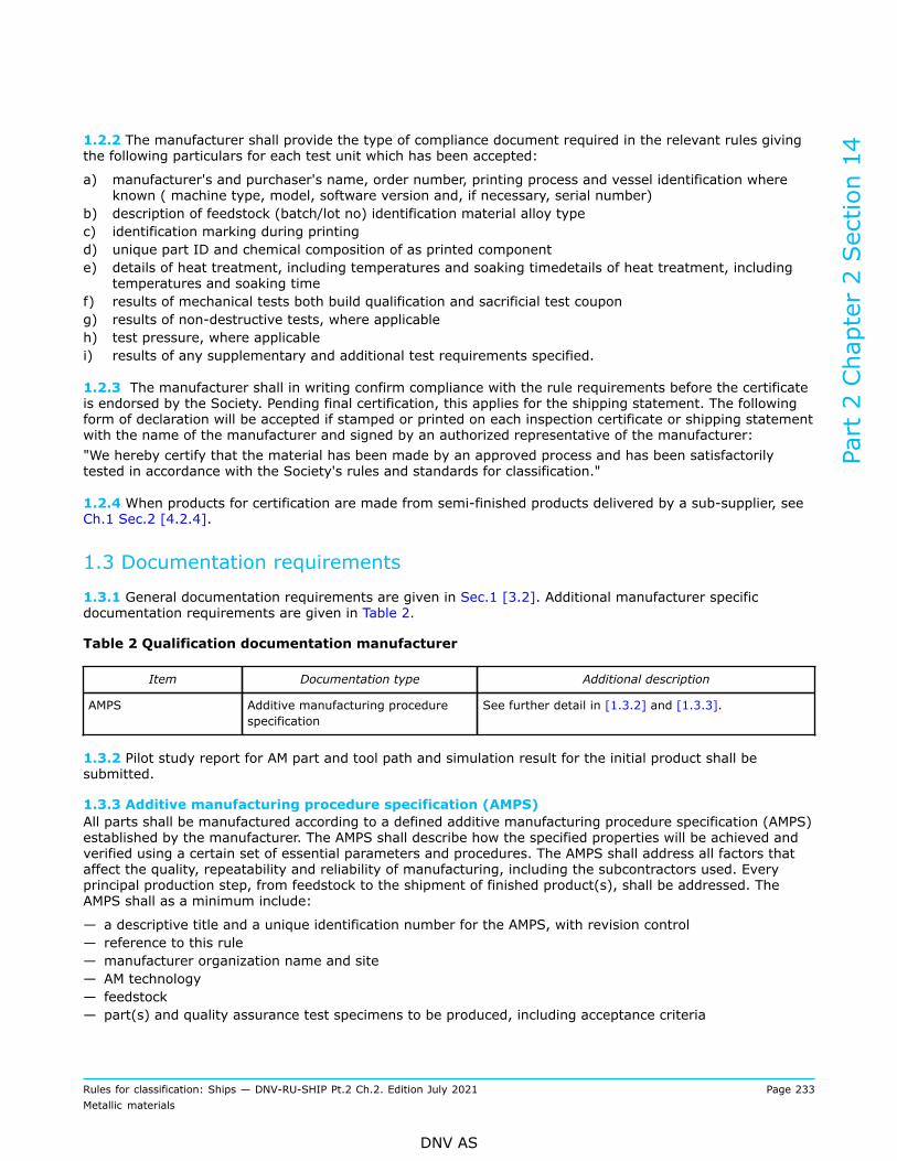
1.2.2 The manufacturer shall provide the type of compliance document required in the relevant rules givingthe following particulars for each test unit which has been accepted:
a) manufacturer's and purchaser's name, order number, printing process and vessel identification whereknown ( machine type, model, software version and, if necessary, serial number)
b) description of feedstock (batch/lot no) identification material alloy typec) identification marking during printingd) unique part ID and chemical composition of as printed componente) details of heat treatment, including temperatures and soaking timedetails of heat treatment, including
temperatures and soaking timef) results of mechanical tests both build qualification and sacrificial test coupong) results of non-destructive tests, where applicableh) test pressure, where applicablei) results of any supplementary and additional test requirements specified.
1.2.3 The manufacturer shall in writing confirm compliance with the rule requirements before the certificateis endorsed by the Society. Pending final certification, this applies for the shipping statement. The followingform of declaration will be accepted if stamped or printed on each inspection certificate or shipping statementwith the name of the manufacturer and signed by an authorized representative of the manufacturer:"We hereby certify that the material has been made by an approved process and has been satisfactorilytested in accordance with the Society's rules and standards for classification."
1.2.4 When products for certification are made from semi-finished products delivered by a sub-supplier, seeCh.1 Sec.2 [4.2.4].
1.3 Documentation requirements
1.3.1 General documentation requirements are given in Sec.1 [3.2]. Additional manufacturer specificdocumentation requirements are given in Table 2.
Table 2 Qualification documentation manufacturer
Item Documentation type Additional description
AMPS Additive manufacturing procedurespecification
See further detail in [1.3.2] and [1.3.3].
1.3.2 Pilot study report for AM part and tool path and simulation result for the initial product shall besubmitted.
1.3.3 Additive manufacturing procedure specification (AMPS)All parts shall be manufactured according to a defined additive manufacturing procedure specification (AMPS)established by the manufacturer. The AMPS shall describe how the specified properties will be achieved andverified using a certain set of essential parameters and procedures. The AMPS shall address all factors thataffect the quality, repeatability and reliability of manufacturing, including the subcontractors used. Everyprincipal production step, from feedstock to the shipment of finished product(s), shall be addressed. TheAMPS shall as a minimum include:
— a descriptive title and a unique identification number for the AMPS, with revision control— reference to this rule— manufacturer organization name and site— AM technology— feedstock— part(s) and quality assurance test specimens to be produced, including acceptance criteria
Part 2 Chapter 2 Section 14
Rules for classification: Ships — DNV-RU-SHIP Pt.2 Ch.2. Edition July 2021 Page 233Metallic materials
DNV AS

— reference to applicable standards or specifications— reference to AoM qualification detail— reference to a part qualification, including the report when an existing part qualification is used— reference to build process qualification record containing information produced during build processqualification, including all essential parameters, log files and test results
— reference to manufacturing procedures— safeguard to ensure traceability of the digital model and manufactured part, e.g. unique ID numbers— design history, if applicable— the number of parts and quality assurance test specimens per build job and their orientation and locationon the build platform. An image of the build platform shall be included. For PBF parts, the location ofsupport structures shall be included
— additional post processing steps including procedures and the sequence— additional processes, if any— testing or inspection requirements in addition to requirements given in this document, if required bypurchaser.Guidance note:Reliability in this respect means the ability of an item to perform a required function under given conditions for a given timeinterval or at a specified condition.
---e-n-d---o-f---g-u-i-d-a-n-c-e---n-o-t-e---
1.4 Survey, inspection and testing requirementsGeneral survey, inspection, and testing requirements are given in Ch.1 Sec.1 [3.3]. Additional specificrequirements are given in Table 3.
Table 3 Additional survey and testing requirements
Survey, inspection and testing item Description
Chemical composition Required for all materials.
Mechanical testing Required for all grades in accordance with the requirements of therelevant section.
Impact toughness test Relevant for all grades where specified in this section.
Impact toughness test of austenitic steel Charpy V-notch impact testing may be omitted if the design temperatureis above -105°C.
Test unit for large AM part (build volume,total usable volume available in the machinefor building parts)
For AM part with length more than 1 m (e.g. by WAAM), two sets ofmechanical tests are required for each test unit. The test blocks shall belocated as widely separated as possible.
Test unit for AM part made from two or morefeedstock batch number
Where large AM parts are made from two or more feedstock batchnumbers, representative sets of mechanical tests are requiredcorresponding to the number of batches involved. The test block shall belocated as widely seperated as possible.
Visual inspection The manufacturer shall carry out visual inspection of all AM part onaccessible surfaces for surface finish and compliance with the dimensionaland geometrical tolerances. If 100% visual inspection is not possibledue to geometrical limitations it shall be noted in the inspection report.Surface roughness shall be reported for fatique sensitive parts.
Part 2 Chapter 2 Section 14
Rules for classification: Ships — DNV-RU-SHIP Pt.2 Ch.2. Edition July 2021 Page 234Metallic materials
DNV AS

Survey, inspection and testing item Description
Visual survey AM part for which certification by the Society is required shall bepresented to the Society for visual inspection. The Society may requireareas to be etched for the purpose of investigating weld repairs.
NDT — The AM part shall be subjected to non-destructive testing as specifiedin the relevant rules for finished machined components. The NDTprocedures shall be established to suit the geometry of the part andthe material.
— where MT or PT is specified, the tests shall be carried out after thefinal heat treatment when the surface is in the final condition, butbefore any cold working. Machined AM part shall be tested afterfinal machining. PT may only be applied where MT is not possible orsuitable and for interpretation of open indications detected by MT
— where UT is specified, the tests shall be carried out after the final heattreatment when the AM part surface has been brought to a conditionsuitable for UT
— where certification by the Society is required, the Society may requestto be present during NDT
— NDT to be accordance to design criteria and allowable defect sizingand corresponding to application. Suitable inspection such as CTscan, digital RT, thermography shall be carried out according to thecriticality of the part.
1.5 Grading system1.5.1 Grade designation related to delivery conditionThe material grade designations related to feedstock for AM products intended for different deliveryconditions are defined as follows:
— F-AM-A: as printed.— F-AM-SR: stress relieve heat treated.— F-AM-SA: solution annealed (e.g. for homogenization).— F-AM-HIP: HIP (hot isostatic pressed).— F-AM-HPHT: HIP (high pressure heat treatment).— F-AM-X: other delivery conditions.
1.5.2 Grade designation related to additive manufacturing techniqueThe grade designation related to AM technology are defined as follows:
— PBF-LB: powder bed fusion for laser beam melting.— PBF-EB: powder bed fusion for electron beam melting.— BPT: blown powder technology.— WAAM: wire arc additive manufacturing.— Other methods: subject to agreement.
Examples of grade designations corresponding to AM delivery conditions can be found in Table 4.
Part 2 Chapter 2 Section 14
Rules for classification: Ships — DNV-RU-SHIP Pt.2 Ch.2. Edition July 2021 Page 235Metallic materials
DNV AS

Table 4 Examples of grade designations
Example DNV grade DesignationCorresponding gradein RU-Ship pt2ch2sec 2 to sec 11
Delivery condition
NV AM -C400UW-A NV AM-additivemanufacturing
C400UW — A: as printed— SR: stress relieve
heat treated— SA: solution
annealed (e.g. forhomogenization)
— HIP: HIP (hotisostatic pressed)
— HPHT: HIP (highpressure heattreatment)
— X: other deliveryconditions
NV AM-F400UW A NV AM-additivemanufacturing
F400UW
NV AM-E36 A NV AM-additivemanufacturing
E36
1.6 Manufacture
1.6.1 All materials delivered with compliance document MC or MD, see Ch.1 Sec.2 [4.2], shall be made atworks approved by the Society for the type, grade and dimensions of material being supplied and for therelevant manufacturing process and delivery condition, see Ch.1 Sec.2 [2.2.2].
1.6.2 It is the manufacturer’s responsibility to ensure that effective manufacture and process controls andwhere relevant, qualified or approved processes are implemented and adhered to in production. Wheredeviation from the controls occurs and this could produce products of inferior quality, the manufacturer shallinvestigate to determine the cause and establish countermeasures to prevent its recurrence. Investigationreports to this effect along with additional information as the Society may require shall be made available tothe Society on request. The frequency and extent of testing for subsequent products is at the discretion ofthe Society.
1.6.3 Process controlUnless otherwise agreed, the testing scope of the production shall be similar to casting and forging asreferred in Sec.6 and Sec.8.It is the manufacturer's responsibility to perform process control check. This shall be verified in accordancewith the AoM program, see DNV-CP-0267.Logged parameters shall be stored in a log-file and be available for review.
1.7 Chemical composition
1.7.1 The chemical composition of each product shall be determined.
1.7.2 The composition shall be determined at a process stage where it will be representative of each productin a test unit.
Part 2 Chapter 2 Section 14
Rules for classification: Ships — DNV-RU-SHIP Pt.2 Ch.2. Edition July 2021 Page 236Metallic materials
DNV AS

1.7.3 When required, the carbon equivalent value (Ceq, Pcm or CET) shall be calculated. For further detailsand formulas, see Ch.1 Sec.2 [3.3].
1.7.4 The manufacturer's declared analysis will be accepted subject to random checks on request by theSociety.
1.8 Condition of supply and heat treatment
1.8.1 Conditions of supply and heat treatment shall be in accordance with the qualified AMPS.
1.9 Test material and test specimens for mechanical testing
1.9.1 Based on the design requirement and application, the material to be tested shall meet the designcriteria. The functional testing requirement shall be according to the design requirements.
1.9.2 The building process should be simulated to aid manufacturing and to avoid foreseeable problemsduring the build job. Simulation may be used to aid quality assurance. Simulation shall not be used as areplacement for other requirements specified in this document.
1.9.3 Test material shall be representative of the sample product and, where appropriate, shall not beseparated from the sample product until heat treatment has been completed. Test material or test specimensshall not be separately heat-treated unless otherwise approved.
1.9.4 The size, thickness location and preparation of test specimens and the procedures used for mechanicaltesting shall in general comply with the relevant requirements of Ch.1 Sec.3, unless specified otherwise inthe qualified manufacturer specification.
1.9.5 Test material shall be suitably marked to identify them with the products represented.
1.9.6 Build axisSee also ISO/ASTM 52921:2013.The build axis may be defined by the manufacturer. It shall be referred in the tool path design and in thespecification (AMPS). and shall be agreed with the Society prior to manufacturing. . Below sketch may beused as basis.
Part 2 Chapter 2 Section 14
Rules for classification: Ships — DNV-RU-SHIP Pt.2 Ch.2. Edition July 2021 Page 237Metallic materials
DNV AS

Z‐axis= for processes emplying planar layerwise addition of material, the axis normal to the layersX‐axis= shall run perpendicular to the Z-axis and parallel to the front of the machineY‐axis= shall run perpendicular to the Z-axis and X-axis with positive direction defined to make a right hand
set of coordinates as specified in ISO 841.
Figure 1 Definition of build axis system (upward building)
1.9.7 Test blocksTest blocks, from which test specimens are taken, shall be printed integrally with the product. The test blocksare either directly printed specimen (e.g. tensile, bend, charpy) or a test block where the specimens areextracted by machining. When this is impracticable, the test blocks shall be printed with and gated to the AMproduct. If the test block cannot be printed along with the product, a separately printed similar block may beaccepted subject to prior agreement. The Societys shall be invited for witnessing of the process of test blockremoval before machining.The size and preparation of test specimens and the procedures used for mechanical testing shall comply withthe relevant requirements of Ch.1 Sec.3.
1.10 Test units and number of tests
1.10.1 Depending on product and grade, provision is made in the approved manufacturer specification fortesting of individual pieces or for batch testing. Where batch testing is permitted, a test unit shall consist ofmaterials of the same product form, from the same feedstock batch, in the same condition of supply and witha total mass not exceeding the agreed limits.
1.10.2 At least one set of relevant mechanical and corrosion tests is required for each test unit, unlessotherwise agreed.
1.11 Mechanical properties
1.11.1 The material shall meet the mechanical properties specified in the agreed specification. E.g.hardness, tensile strength, impact strength compressive strength, flexural strength, fatigue strength, creep,ageing, frictional coefficient, shear resistance, and crack extension.
Part 2 Chapter 2 Section 14
Rules for classification: Ships — DNV-RU-SHIP Pt.2 Ch.2. Edition July 2021 Page 238Metallic materials
DNV AS

1.11.2 If the results do not meet the specified requirements, the re-test procedures in Ch.1 Sec.2 [3.8]may be adopted. Where the products are submitted to heat treatment or re-heat treatment, all the testspreviously performed shall be repeated and the results shall meet the specified requirements.
1.12 Inspection and tolerances
1.12.1 Surface inspection and verification of dimensions including shape and straightness are theresponsibility of the manufacturer. Acceptance by the Society of material later found to be defective shall notabsolve the manufacturer from this responsibility.The manufacturer shall submit and agree on inspection and test plan with the Society prior to printing.The manufacturer shall carry out visual inspection of all AM parts on accessible surfaces for surface finish andcompliance with the dimensional and geometrical tolerances.
1.12.2 Products shall be subjected to a thorough, visual inspection by the manufacturer to ensure freedomfrom defects and harmful imperfections, and have a workmanlike finish, appearance, texture and colourconsistent with the method of manufacture and an agreed specification, and shall be free from internal andsurface defects, warping, hot tear or other defect prejudicial to the use of the material for the intendedapplication. Where applicable, this shall include the inspection of internal surfaces and bores. The surfacesshall be adequately prepared for inspection. if internal surface is not accessible due to geometry it shall betested by suitable NDT methodSuitable preparation methods for visual inspection include pickling, caustic cleaning, wire brushing, localgrinding, shot or sand blasting. The surfaces shall not be hammered, peened or treated in any way whichmay obscure discontinuities.AM part for which certification by the Society is required shall be presented to the Society for visualinspection. The Society may require areas to be etched for the purpose of investigating weld repairs.
1.12.3 The dimensional tolerances shall be according to an agreed specification.
1.12.4 The non-destructive testing (NDT) shall be according to an agreed specification and design criteria,and allowable defects size specified corresponding to given application. Suitable inspection like CT scan,digital RT, or thermography shall be carried out according to the criticality of the part.
1.12.5 Density shall fulfil the following: for PBF > 99% and for MBJ > 97%. For other AM processes thedensity shall be specified and agreed.
1.12.6 Other physical properties, microstructure analysis, etc. may be specified and agreed.
1.13 Repair
1.13.1 Surface defects may be removed by localized grinding followed by proper NDT to prove completeelimination of the defects, provided that the remaining dimensions are within the dimensional tolerances ofthe product in question.
1.13.2 Repair by other methods, including welding, is not permitted unless qualified and agreed.
1.13.3 The manufacturer shall maintain records of repairs, subsequent heat treatment and inspectionstraceable to each product repaired. The records shall be presented to the Society on request.
1.14 Identification
1.14.1 Every finished product shall be clearly marked by the manufacturer in at least one place with thedetails specified in Ch.1 Sec.2 [4.1.3].
Part 2 Chapter 2 Section 14
Rules for classification: Ships — DNV-RU-SHIP Pt.2 Ch.2. Edition July 2021 Page 239Metallic materials
DNV AS

Each AM part which has been tested and inspected with satisfactory results shall also be identified by themanufacturer with the following:
— product number or other marking which will enable the full history of the AM process to be traced— the unique identification number, where applicable and as furnished by the Society— test pressure, where applicable.
In case of AM parts of very small size (e.g. by PBF), other identification systems may be agreed with theSociety.
Part 2 Chapter 2 Section 14
Rules for classification: Ships — DNV-RU-SHIP Pt.2 Ch.2. Edition July 2021 Page 240Metallic materials
DNV AS
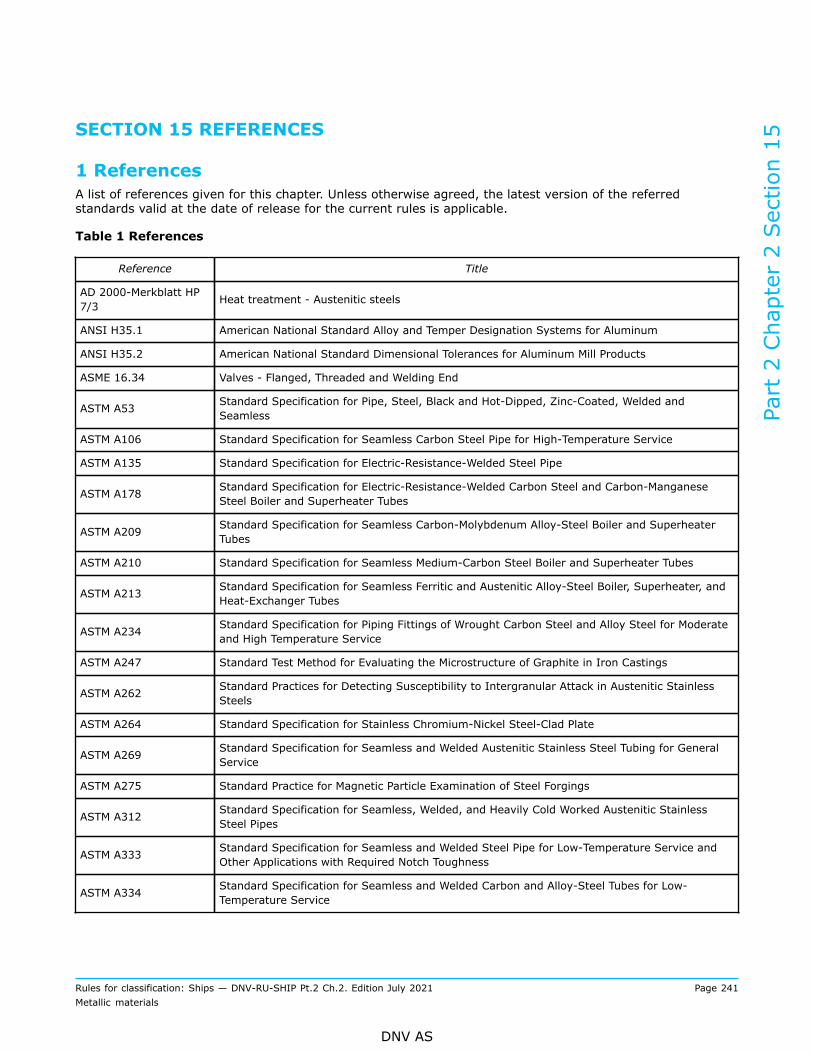
SECTION 15 REFERENCES
1 ReferencesA list of references given for this chapter. Unless otherwise agreed, the latest version of the referredstandards valid at the date of release for the current rules is applicable.
Table 1 References
Reference Title
AD 2000-Merkblatt HP7/3 Heat treatment - Austenitic steels
ANSI H35.1 American National Standard Alloy and Temper Designation Systems for Aluminum
ANSI H35.2 American National Standard Dimensional Tolerances for Aluminum Mill Products
ASME 16.34 Valves - Flanged, Threaded and Welding End
ASTM A53 Standard Specification for Pipe, Steel, Black and Hot-Dipped, Zinc-Coated, Welded andSeamless
ASTM A106 Standard Specification for Seamless Carbon Steel Pipe for High-Temperature Service
ASTM A135 Standard Specification for Electric-Resistance-Welded Steel Pipe
ASTM A178 Standard Specification for Electric-Resistance-Welded Carbon Steel and Carbon-ManganeseSteel Boiler and Superheater Tubes
ASTM A209 Standard Specification for Seamless Carbon-Molybdenum Alloy-Steel Boiler and SuperheaterTubes
ASTM A210 Standard Specification for Seamless Medium-Carbon Steel Boiler and Superheater Tubes
ASTM A213 Standard Specification for Seamless Ferritic and Austenitic Alloy-Steel Boiler, Superheater, andHeat-Exchanger Tubes
ASTM A234 Standard Specification for Piping Fittings of Wrought Carbon Steel and Alloy Steel for Moderateand High Temperature Service
ASTM A247 Standard Test Method for Evaluating the Microstructure of Graphite in Iron Castings
ASTM A262 Standard Practices for Detecting Susceptibility to Intergranular Attack in Austenitic StainlessSteels
ASTM A264 Standard Specification for Stainless Chromium-Nickel Steel-Clad Plate
ASTM A269 Standard Specification for Seamless and Welded Austenitic Stainless Steel Tubing for GeneralService
ASTM A275 Standard Practice for Magnetic Particle Examination of Steel Forgings
ASTM A312 Standard Specification for Seamless, Welded, and Heavily Cold Worked Austenitic StainlessSteel Pipes
ASTM A333 Standard Specification for Seamless and Welded Steel Pipe for Low-Temperature Service andOther Applications with Required Notch Toughness
ASTM A334 Standard Specification for Seamless and Welded Carbon and Alloy-Steel Tubes for Low-Temperature Service
Part 2 Chapter 2 Section 15
Rules for classification: Ships — DNV-RU-SHIP Pt.2 Ch.2. Edition July 2021 Page 241Metallic materials
DNV AS

ASTM A335 Standard Specification for Seamless Ferritic Alloy-Steel Pipe for High-Temperature Service
ASTM A358 Standard Specification for Electric-Fusion-Welded Austenitic Chromium-Nickel Stainless SteelPipe for High-Temperature Service and General Applications
ASTM A370 Standard Test Methods and Definitions for Mechanical Testing of Steel Products
ASTM A388 Standard Practice for Ultrasonic Examination of Steel Forgings
ASTM A403 Standard Specification for Wrought Austenitic Stainless Steel Piping Fittings
ASTM A420 Standard Specification for Piping Fittings of Wrought Carbon Steel and Alloy Steel for Low-Temperature Service
ASTM A578 Standard Specification for Straight-Beam Ultrasonic Examination of Rolled Steel Plates forSpecial Applications
ASTM A609 Standard Practice for Castings, Carbon, Low-Alloy, and Martensitic Stainless Steel, UltrasonicExamination Thereof
ASTM A744 Standard Specification for Castings, Iron-Chromium-Nickel, Corrosion Resistant, for SevereService
ASTM A770 Standard Specification for Through-Thickness Tension Testing of Steel Plates for SpecialApplications
ASTM A789 Standard Specification for Seamless and Welded Ferritic/Austenitic Stainless Steel Tubing forGeneral Service
ASTM A790 Standard Specification for Seamless and Welded Ferritic/Austenitic Stainless Steel Pipe
ASTM A815 Standard Specification for Wrought Ferritic, Ferritic/Austenitic, and Martensitic Stainless SteelPiping Fittings
ASTM A928 Standard Specification for Ferritic/Austenitic (Duplex) Stainless Steel Pipe Electric FusionWelded with Addition of Filler Metal
ASTM A960 Standard Specification for Common Requirements for Wrought Steel Piping Fittings
ASTM A961 Standard Specification for Common Requirements for Steel Flanges, Forged Fittings, Valves,and Parts for Piping Applications
ASTM A965 Standard Specification for Steel Forgings, Austenitic, for Pressure and High Temperature Parts
ASTM A991 Standard Test Method for Conducting Temperature Uniformity Surveys of Furnaces Used toHeat Treat Steel Products
ASTM B111 Standard Specification for Copper and Copper-Alloy Seamless Condenser Tubes and FerruleStock
ASTM B338 Standard Specification for Seamless and Welded Titanium and Titanium Alloy Tubes forCondensers and Heat Exchangers
ASTM B543 Standard Specification for Welded Copper and Copper-Alloy Heat Exchanger Tube
ASTM B861 Standard Specification for Titanium and Titanium Alloy Seamless Pipe
ASTM B862 Standard Specification for Titanium and Titanium Alloy Welded Pipe
ASTM B928 Standard Specification for High Magnesium Aluminum-Alloy Products for Marine Service andSimilar Environments
ASTM E94 Standard Guide for Radiographic Examination Using Industrial Radiographic Film
Part 2 Chapter 2 Section 15
Rules for classification: Ships — DNV-RU-SHIP Pt.2 Ch.2. Edition July 2021 Page 242Metallic materials
DNV AS

ASTM E165 Standard Practice for Liquid Penetrant Examination for General Industry
ASTM E709 Standard Guide for Magnetic Particle Testing
ASTM G48 Standard Test Methods for Pitting and Crevice Corrosion Resistance of Stainless Steels andRelated Alloys by Use of Ferric Chloride Solution
ASTM G66 Standard Test Method for Visual Assessment of Exfoliation Corrosion Susceptibility of 5XXXSeries Aluminum Alloys (ASSET Test)
ASTM G67 Standard Test Method for Determining the Susceptibility to Intergranular Corrosion of 5XXXSeries Aluminum Alloys by Mass Loss After Exposure to Nitric Acid (NAMLT Test)
DIN 267-13 Fasteners - Technical specifications - Part 13: Parts for bolted connections with specificmechanical properties for use at temperatures ranging from -200°C to +700 °C
DIN 50162 Testing of clad steels; determination of shear strength between cladding metal and parentmetal in shear test
DNV-ST-B203 Additive manufacturing of metallic parts
EN 515 Aluminium and aluminium alloys - Wrought products - Temper designations
EN 1011-2 Welding - Recommendations for welding of metallic materials - Part 2: Arc welding of ferriticsteels
EN 1369 Founding - Magnetic particle testing
EN 1371-1 Founding - Liquid penetrant testing - Part 1: Sand, gravity die and low pressure die castings
EN 1563 Founding - Spheroidal graphite cast irons
EN 1706 Aluminium and aluminium alloys - Castings - Chemical composition and mechanical properties
EN 10028 series Flat products made of steels for pressure purposes
EN 10088 series Stainless steels
EN 10160 Ultrasonic testing of steel flat product of thickness equal or greater than 6 mm (reflectionmethod)
EN 10163-1Delivery requirements for surface condition of hot-rolled steel plates, wide flats and sections
Part 1: General requirements
EN 10163-2Delivery requirements for surface condition of hot-rolled steel plates, wide flats and sections
Part 2: Plate and wide flats
EN 10163-3Delivery requirements for surface condition of hot-rolled steel plates, wide flats and sections
Part 3: Sections
EN 10164 Steel products with improved deformation properties perpendicular to the surface of theproduct - Technical delivery conditions
EN 10216-1 Seamless steel tubes for pressure purposes - Technical delivery conditions - Part 1: Non-alloysteel tubes with specified room temperature properties
EN 10216-2 Seamless steel tubes for pressure purposes - Technical delivery conditions - Part 2: Non-alloyand alloy steel tubes with specified elevated temperature properties
EN 10216-3 Seamless steel tubes for pressure purposes - Technical delivery conditions - Part 3: Alloy finegrain steel tubes
Part 2 Chapter 2 Section 15
Rules for classification: Ships — DNV-RU-SHIP Pt.2 Ch.2. Edition July 2021 Page 243Metallic materials
DNV AS

EN 10216-4 Seamless steel tubes for pressure purposes - Technical delivery conditions - Part 4: Non-alloyand alloy steel tubes with specified low temperature properties
EN 10216-5 Seamless steel tubes for pressure purposes - Technical delivery conditions - Part 5: Stainlesssteel tubes
EN 10217-1 Welded steel tubes for pressure purposes - Technical delivery conditions - Part 1: Non-alloysteel tubes with specified room temperature properties
EN 10217-2 Welded steel tubes for pressure purposes - Technical delivery conditions - Part 2: Electricwelded non-alloy and alloy steel tubes with specified elevated temperature properties
EN 10217-3 Welded steel tubes for pressure purposes - Technical delivery conditions - Part 3: Alloy finegrain steel tubes
EN 10217-6 Welded steel tubes for pressure purposes - Technical delivery conditions - Part 6: Submergedarc welded non-alloy steel tubes with specified low temperature properties
EN 10217-7 Welded steel tubes for pressure purposes - Technical delivery conditions - Part 7: Stainlesssteel tubes
EN 10222 series Steel forgings for pressure purposes
EN 10225 series Weldable structural steels for fixed offshore structures - Technical delivery conditions
EN 10228-1 Non-destructive testing of steel forgings - Part 1: Magnetic particle inspection
EN 10228-2 Non-destructive testing of steel forgings - Part 2: Penetrant testing
EN 10228-3 Non-destructive testing of steel forgings - Part 3: Ultrasonic testing of ferritic or martensiticsteel forgings
EN 10228-4 Non-destructive testing of steel forgings - Part 4: Ultrasonic testing of austenitic and austenitic-ferritic stainless steel forgings
EN 10253 series Butt-welding pipe fittings
EN 12449 Copper and copper alloys - Seamless, round tubes for general purposes
EN 12451 Copper and copper alloys - Seamless, round tubes for heat exchangers
EN 12452 Copper and copper alloys - Rolled, finned, seamless tubes for heat exchangers
EN 12680-3 Founding - Ultrasonic testing - Part 3: Spheroidal graphite cast iron castings
EN 12681 Founding - Radiographic examination
EN ISO 10893-2 Non-destructive testing of steel tubes - Part 2: Automated eddy current testing of seamlessand welded (except submerged arc-welded) steel tubes for the detection of imperfections
EN ISO 10893-3Non-destructive testing of steel tubes - Part 3: Automated full peripheral flux leakage testingof seamless and welded (except submerged arc-welded) ferromagnetic steel tubes for thedetection of longitudinal and/or transverse imperfections
EN ISO 10893-6 Non-destructive testing of steel tubes - Part 6: Radiographic testing of the weld seam of weldedsteel tubes for the detection of imperfections
EN ISO 10893-11 Non-destructive testing of steel tubes - Part 11: Automated ultrasonic testing of the weld seamof welded steel tubes for the detection of longitudinal and/or transverse imperfections
IACS Rec. 68 Guidelines for non-destructive examination of hull and machinery steel forgings
IACS Rec. 69 Guidelines for non-destructive examination of marine steel castings
Part 2 Chapter 2 Section 15
Rules for classification: Ships — DNV-RU-SHIP Pt.2 Ch.2. Edition July 2021 Page 244Metallic materials
DNV AS

IACS UR W9 Grey iron castings
IACS UR W10 Spheroidal or nodular graphite iron castings
ISO 3452-1 Non-destructive testing - Penetrant testing - Part 1: General principles
ISO 4967 Steel - Determination of content of non-metallic inclusions - Micrographic method usingstandard diagrams
ISO 5579 Non-destructive testing - Radiographic testing of metallic materials using film and X- or gammarays - Basic rules
ISO 6892-2 Metallic materials - Tensile testing - Part 2: Method of test at elevated temperature
ISO 9329-1 Seamless steel tubes for pressure purposes - Technical delivery conditions - Part 1: Unalloyedsteels with specified room temperature properties
ISO 9329-2 Seamless steel tubes for pressure purposes - Technical delivery conditions - Part 2: Unalloyedand alloyed steels with specified elevated temperature properties
ISO 9329-3 Seamless steel tubes for pressure purposes - Technical delivery conditions - Part 3: Unalloyedand alloyed steels with specified low temperature properties
ISO 9329-4 Seamless steel tubes for pressure purposes - Technical delivery conditions - Part 4: Austeniticstainless steels
ISO 9330-1 Welded steel tubes for pressure purposes - Technical delivery conditions - Part 1: Unalloyedsteel tubes with specified room temperature properties
ISO 9330-2Welded steel tubes for pressure purposes - Technical delivery conditions - Part 2: Electricresistance and induction welded unalloyed and alloyed steel tubes with specified elevatedtemperature properties
ISO 9330-3Welded steel tubes for pressure purposes - Technical delivery conditions - Part 3: Electricresistance and induction welded unalloyed and alloyed steel tubes with specified lowtemperature properties
ISO 9330-6 Welded steel tubes for pressure purposes - Technical delivery conditions - Part 6: Longitudinallywelded austenitic stainless steel tubes
ISO 9712 Non-destructive testing - Qualification and certification of NDT personnel
ISO 10474 Steel and steel products - Inspection documents
ISO 10893 series Non-destructive testing of steel tubes
ISO 15614-1 Specification and qualification of welding procedures for metallic materials - Welding proceduretest - Part 1: Arc and gas welding of steels and arc welding of nickel and nickel alloys
ISO/ASTM 52900 Additive manufacturing - General principles - Terminology
ISO/ASTM 52921 Standard terminology for additive manufacturing - Coordinate systems and test methodologies
JIS B2312 Steel butt-welding pipe fittings
JIS B2313 Steel plate butt-welding pipe fittings
JIS B2316 Steel socket-welding pipe fittings
JIS G3214 Stainless steel forgings for pressure vessels
JIS G3454 Carbon steel pipes for pressure service
JIS G3455 Carbon steel pipes for high pressure service
Part 2 Chapter 2 Section 15
Rules for classification: Ships — DNV-RU-SHIP Pt.2 Ch.2. Edition July 2021 Page 245Metallic materials
DNV AS

JIS G3456 Carbon steel pipes for high temperature service
JIS G3458 Alloy steel pipes
JIS G3459 Stainless steel pipes
JIS G3460 Steel tubes for low temperature service
JIS G3461 Carbon steel boiler and heat exchanger tubes
JIS G3462 Alloy steel tubes for boiler and heat exchanger
JIS G3463 Stainless steel boiler and heat exchanger tubes
JIS H3300 Copper and copper alloy seamless pipes and tubes
JIS H3320 Copper and copper alloy welded pipes and tubes
MIL-J-24445A Military specification for joint, bimetallic bonded, aluminum to steel
RESOLUTIONMSC.289(87) of SOLASCh. II-1, Pt. A-1, Reg.3-11
Performance standard for alternative means of corrosion protection for cargo oil tanks of crudeoil tankers
Part 2 Chapter 2 Section 15
Rules for classification: Ships — DNV-RU-SHIP Pt.2 Ch.2. Edition July 2021 Page 246Metallic materials
DNV AS

CHANGES – HISTORIC
July 2020 edition
Changes July 2020, entering into force 1 January 2021Topic Reference Description
WPS for products to becertified
Sec.1 [3] Location of WPS requirement amended such that it is relevantfor qualification documentation for the manufacturer, but not fordocumentation for the product to be certified.
Z-quality steels: retestingrequirements
Sec.2 [6.5.2] Clarification that already one obtained value which is less thanthe minimum individual value is a cause for rejection.
BCA1 and BCA2 steel grades Sec.2 [7] Updated IACS UR W31 with entry into force on 1st Jan 2021.Added new BCA2 grade with min. Kca ≥ 8000 N/mm3/2 whichmay be applied for areas requiring higher brittle crack arrestproperties. Previous steel grade BCA is renamed to BCA1.
Higher ductility (HD) steels Sec.2 [10] Added requirements for the manufacture, testing andidentification of HD steels.
Charpy testing for material forapplication as per IGC
Sec.3 [1.11], Sec.5[1], Sec.5 [6]
Normally, charpy testing is not required for thickness less than6 mm. However, for IGC application charpy testing is requiredalso for smaller thicknesses.
Cold forming on VL Mn 400steel
Sec.3 [5.2] For this steel grade cold forming of up to 5 % does not requiresubsequent heat treatment. Adding of grade VL Mn 400 torelevant table.
Pipes for pressure systems Sec.5 [2.2.1] The steel grades given by EN 10305 Part 1 and 2 have beenlimited to those with delivery condition N - normalised.
Pipes for pressure systems -Kv requirements
Sec.5 [2.4.1] Wording amended such that higher requirements specified byapplied standards may be applicable.
Starting materials for fittings Sec.5 [6.3] Specification that AoM for starting material manufacturer is onlyneeded for fittings which shall be delivered with VL or works(W) certificate.
Heat treatment Sec.6 [1.8.3] As example DNVGL-CP-0351 Manufacture of heat treatedproducts was added.
Charpy testing for forgingsintended for low temperatureapplication
Sec.6 Table 6 Specification that, unless specified, the test temperature fordesign temperatures below -10ºC shall be impact tested at 5ºCbelow the design temperature.
Clean steel forgings Sec.6 [4.1] Clarification that only in case of clean steel forgings specificrequirements are applicable.
Pressure testing - relevantstandards to be added, andrelevant materials to be added
Sec.6 [6.6], Sec.9[1.10.4], Sec.11 [2.5]
Wording added that pressure testing shall be performed inaccordance with a recognized standard. Requirement forpressure testing added for pressure retaining stainless steelcastings.
Steel forgings for lowtemperature
Sec.6 [7] Grade VL F1.5Ni added in Table 12 and Table 13.
Part 2 Chapter 2 Changes – historic
Rules for classification: Ships — DNV-RU-SHIP Pt.2 Ch.2. Edition July 2021 Page 247Metallic materials
DNV AS

Topic Reference Description
Design temperature limitationsfor stainless steel forgings andcastings
Sec.6 [8.1.4]
Sec.8 [7.1.2]
Design temperature limitations are specified for austenitic andduplex (ferritic/austenitic) steels.
Materials for bolts intended forpressure equipment
Sec.6 [9.2] Materials in accordance with industrial standards, such as ISO898 1 and 2, do not comply with rules for pressure equipment.Reference to relevant (more strict) mechanical properties havebeen added.
Nuts - KV testing no longerrequired
Sec.6 [9.3] Wording amended such that KV testing is not required for nuts.
Bolts - tensile test, testing asper standards
Sec.6 [9.5] Include test types as per the relevant standards.
Steel castings for anchors: finegrain treatment
Sec.8 Table 4 Wording added that steel castings for anchors shall be fine graintreated with aluminium.
Nodular cast iron: solidsolution strengthened ferriticgrades
Sec.9 [2] Added new developed solid solution strengthened ferritic gradeshave enhanced elongation behaviour which is beneficial formaritime application.
Copper alloy castings Sec.11 [1.6.1] Specification that approval of manufacturer (AoM) for copperalloy foundries is only needed when castings shall be deliveredwith VL or works (W) certificate.
July 2019 edition
Changes July 2019, entering into force 1 January 2020Topic Reference Description
Details of heat treatment onmaterial certificate for QTsteels
Sec.2 [2.1.2] andSec.3 [1.2.2]
Clarified that for QT steels the tempering temperature orrecommended post-weld heat treatment temperature shall beincluded in the certificate.
Details of heat treatment onmaterial certificate
Sec.2 [2.1.2] Clarified requirements for specification of heat treatmenttemperatures to be given on material certificate.
Impact test requirementsfor VL D47 / VL E47 steelswithout BCA, COD or BCACOD:clarification
Sec.2 [2.8] Corrected text such that for the grades VL D/E47 withoutsuffixes BCA, COD or BCACOD, impact testing for t/2 is notrequired.
Impact testing direction forVL D47 and VL E47, with/without BCA, COD, BCACOD:clarification
Sec.2 [2.8.6] Clarified that for these grades impact testing direction shall belongitudinal.
EN ISO 10893-6: acceptancecategory
Sec.2 [2.11.9] Acceptance category for RT (analogue) EN ISO 10893-6 iscorrected to the requirements specified therein.
Welded hollow sections:automated NDT
Sec.2 Table 4 Table added, containing the previous as well as furtherstandards for NDT of welded hollow sections. For definitionof automated NDT, and for appropriate acceptance criteria,reference to the corresponding standards are added.
Part 2 Chapter 2 Changes – historic
Rules for classification: Ships — DNV-RU-SHIP Pt.2 Ch.2. Edition July 2021 Page 248Metallic materials
DNV AS
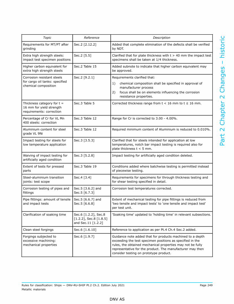
Topic Reference Description
Requirements for MT/PT aftergrinding
Sec.2 [2.12.2] Added that complete elimination of the defects shall be verifiedby NDT.
Extra high strength steels:impact test specimen positions
Sec.2 [5.5] Clarified that for plate thickness with t > 40 mm the impact testspecimens shall be taken at 1/4 thickness.
Higher carbon equivalent forextra high strength steels
Sec.2 Table 15 Added subnote to indicate that higher carbon equivalent maybe approved.
Corrosion resistant steelsfor cargo oil tanks: specifiedchemical composition
Sec.2 [9.2.1] Requirements clarified that:
1) chemical composition shall be specified in approval ofmanufacturer process
2) focus shall be on elements influencing the corrosionresistance properties.
Thickness category for t =16 mm for yield strengthrequirements: correction
Sec.3 Table 5 Corrected thickness range from t < 16 mm to t ≤ 16 mm.
Percentage of Cr for VL Mn400 steels: correction
Sec.3 Table 12 Range for Cr is corrected to 3.00 - 4.00%.
Aluminium content for steelgrade VL 9Ni
Sec.3 Table 12 Required minimum content of Aluminium is reduced to 0.010%.
Impact testing for steels forlow temperature application
Sec.3 [3.5.3] Clarified that for steels intended for application at lowtemperatures, notch bar impact testing is required also forplate thickness t < 5 mm.
Waiving of impact testing forartificially aged condition
Sec.3 [5.2.8] Impact testing for artificially aged condition deleted.
Extent of tests for pressedparts
Sec.3 Table 19 Conditions added where batchwise testing is permitted insteadof piecewise testing.
Steel-aluminium transitionjoints: test scope
Sec.4 [3.4] Requirements for specimens for through thickness testing andfor shear testing specified in detail.
Corrosion testing of pipes andfittings
Sec.5 [3.6.2] andSec.5 [6.7.3]
Corrosion test temperatures corrected.
Pipe fittings: amount of tensileand impact tests
Sec.5 [6.6.7] andSec.5 [6.6.8]
Extent of mechanical testing for pipe fittings is reduced from'two tensile and impact tests' to 'one tensile and impact test'per test unit.
Clarification of soaking time Sec.6 [1.2.2], Sec.8[1.2.2], Sec.8 [1.8.5]and Sec.11 [1.2.2]
'Soaking time' updated to 'holding time' in relevant subsections.
Clean steel forgings Sec.6 [1.6.10] Reference to application as per Pt.4 Ch.4 Sec.2 added.
Forgings subjected toexcessive machining:mechanical properties
Sec.6 [1.9.7] Guidance note added that for products machined to a depthexceeding the test specimen positions as specified in therules, the obtained mechanical properties may not be fullyrepresentative for the product. The manufacturer may thenconsider testing on prototype product.
Part 2 Chapter 2 Changes – historic
Rules for classification: Ships — DNV-RU-SHIP Pt.2 Ch.2. Edition July 2021 Page 249Metallic materials
DNV AS

Topic Reference Description
Forgings exposed to low airtemperature / for cold climateapplication
Sec.6 Table 8 Note added for forgings intended for exposure to low airtemperature / for cold climate application. Reference to Pt.4Ch.1 Sec.3 added.
Steel forgings for lowtemperature application
Sec.6 [7] Two new grades are implemented, and impact toughnessrequirements for nickel alloy grades are corrected.
Requirements for bolts andnuts
Sec.6 [9] Clarification of mechanical properties for 'applicationfor pressure equipment' and 'other application'. Testingrequirements and acceptance criteria aligned with thecorresponding requirements for other forgings as per Sec.6 [2]to Sec.6 [8]. Test batch size and test scope clarified.
Chain cables: heattreatment requirementsrecommended by the chaincable manufacturer
Sec.7 [2.2.2] Added that where chain cables are supplied in the as-rolledcondition, for the simulated heat-treatment, the parametersrecommended by the manufacturer for the chain cable shall beused.
July 2018 edition
Changes July 2018, entering into force 1 January 2019Topic Reference Description
Corrosion testing for stainlesssteel castings
Sec.8 [7.5] Wording amended making clear that intercrystalline corrosion(IK) testing shall be performed as required by the relevantconstruction rules.
Required details forcertification
Sec.2 [2.1] Information added on required details for the certificate,such as weight percentage of elements added for improvingcorrosion resistance, Ceq, heat treatment temperatures andinspection results.
Subsection restructured for better overview on the variousrequirements for manufacture, test units, test scope andmechanical properties considering dimensions lower than 16mm, lower than 39 mm and higher or equal to 39 mm.
Overview of requirements Sec.6 [9]
Amendment of test temperature from 25°C ± 5°C to 23°C± 5°C, which is standard definition of room temperature formechanical testing.
Small scale testing for BCAsteel grades
Sec.2 [7] Reference to DNVGL-CG-0240 added, providing informationabout appropriate process for conducting small scale tests.
Documentation requirementsfor testing for BCA steelgrades
Sec.2 [2.2] Documentation requirements added for large and small scaletesting for BCA steel grades.
Surface finish requirements forpipes
Sec.5 [1.11] Specific requirements provided for surface finish, consideringmanufacturing route and imperfections detrimental to theproduct, as well as minor surface discontinuities.
Part 2 Chapter 2 Changes – historic
Rules for classification: Ships — DNV-RU-SHIP Pt.2 Ch.2. Edition July 2021 Page 250Metallic materials
DNV AS

January 2018 edition
Changes January 2018, entering into force as from date ofpublication
Topic Reference Description
Updated IACS UR W11 Sec.2 [2.7], Sec.2[2.11], Sec.2 [2.12]
Terminology for rolling procedures in Sec.2 [2.7] alignedwith IACS UR W11; clarification of surface quality and NDTrequirements in Sec.2 [2.11] and Sec.2 [2.12].
Temperature for impact testingfor VL B
Sec.2 Table 6 Temperature for impact test changed from +20°C to 0°C.
Impact test for VL A / VL B Sec.2 Table 6 Remark is added in note 3), stating that the impact toughnessfor grade VL A and VL B shall be verified within manufacturerapproval process.
Acid soluble content Sec.2 Table 8 Clarified specification of acid soluble aluminium content.
High Manganese grades Sec.3 [3.2], Sec.3[3.4], Sec.3 [3.5]
Added Mn alloy grades in Sec.3 [3.2]. Included basicrequirements for Mn alloy grades, in terms of chemicalcomposition Sec.3 [3.3], heat treatment condition Sec.3 [3.4]and mechanical properties Sec.3 [3.5].
Pipe grades acc. to EN 10305 Sec.5 [2.2] EN 10305-1 and EN 10305-2 included.
Forging ratio and ratio forupsetting
Sec.6 Table 3 Table revised to precisely state requirements regarding forgingratio.
Additional options forcertification of steel grades
Sec.2 Table 16 Increase of application thickness for D/E47 grades to 3-100mm.
July 2017 edition
Changes July 2017, entering into force 1 January 2018Topic Reference Description
Hardness values forextra high tensile steels.
Sec.2 [5.5.1] Note implemented in Table 16 which indicates recommended maximumhardness values for materials exposed to anaerobic environments or tocathodic protection.
Detaching of testmaterial with regards toheat treatment.
Sec.6 [1.9.1] toSec.6 [1.9.4]
Clarified rules' text when detaching of test material from the forging itrepresents is permitted. The structure of the rules concerning samplingis improved. A paragraph was added to ensure that test material mustbe subjected to the same heat treatment as the forging it represents.
Withdrawn standardEN 20898 for bolts andnuts.
Sec.6 [9.2.2] Deleted withdrawn standard EN 20898, which is fully replaced by ISO898-1 and -2.
Specimen extraction forbolts and nuts > M39.
Sec.6 [9] Wording is modified in order that the requirements for bolts > M39 arestated more clear. Distinguishing between requirements for startingmaterial and final product is improved.
Part 2 Chapter 2 Changes – historic
Rules for classification: Ships — DNV-RU-SHIP Pt.2 Ch.2. Edition July 2021 Page 251Metallic materials
DNV AS

Topic Reference Description
Missing duplex stainlesssteel grades for castings.
Sec.8 [7.2] andSec.8 [7.4]
Duplex stainless steel grades added in the rules, as well as theirappropriate requirements for chemical composition in Table 15 andmechanical properties in Table 16.
Corrosion testing ofrolled 5xxx aluminiumalloys
Sec.10 [1.11.1] Amendment of affected grades / conditions as follows: rolled 5000 seriesalloys of grade 5083, 5383, 5059, 5086 and 5456 in the H116 and H321temper condition which are intended for use in marine hull constructionor in marine applications where frequent direct contact with seawater isexpected shall be tested with respect to exfoliation and inter-granularcorrosion resistance.
January 2017 edition
Main changes January 2017, entering into force 1 July 2017
• Sec.2 Rolled steel for structural application— Sec.2 Table 1: Heat treatment conditions amended and parameters for recording added— Sec.2 Table 2: BCA / COD grades included to 'Through thickness tensile test' resp. 'Fracture mechanicstest'
— Sec.2 Table 6: Toughness of VL A ≤ 50 mm and VL B ≤ 25 mm specified— Sec.2 Table 16: Adjustment of grade specification and footnotes 3) and 4)— Sec.2 Table 17: Footnote for grades 890MPa and 960MPa implemented— Sec.2 [5.1]: Grades 890MPa and 960MPa included
• Sec.3 Rolled steel for boilers, pressure vessels and special applications— Sec.3 [1.9.5]: Consideration of limitation of the yield to tensile ratio— Sec.3 [1.14]: Including of standards for intercrystalline corrosion testing— Sec.3 [3.2.1]: Including option to approve steel grades with t > 40 mm— Sec.3 [4.6]: Including of standards for intercrystalline corrosion testing
• Sec.5 Steel pipes and fittings— Sec.5 [1.5.5]: Consideration of limitation of the yield to tensile ratio— Sec.5 [1.10]: Definition of applicable test pressure for hydrostatic leak-tightness test— Sec.5 [3.6.2]: Deviation of testing temperature to be +/-2°C implemented— Sec.5 [4.1.1]: Consideration of pipes with thickness t>25 mm included— Sec.5 Table 3: Heat treatment condition included— Sec.5 [5.3]: Manufacturing processes updated with "cold finished electric resistance or induction weldedfollowed by heat treatment"
— Sec.5 [6.7.3]: Deviation of testing temperature to be +/-2°C implemented
• Sec.6 Steel forgings— Sec.6 [1.8.3]: Location of thermocouples on furnace charge during heat treatment— Sec.6 Figure 4: Placement of specimen on the driven side of crankshaft revised— Sec.6 [8.3.1]: Wording amended for Charpy V-notch testing for stainless steels other than austeniticstainless steels
Part 2 Chapter 2 Changes – historic
Rules for classification: Ships — DNV-RU-SHIP Pt.2 Ch.2. Edition July 2021 Page 252Metallic materials
DNV AS

• Sec.8 Steel castings— Sec.8 [1.6.4]: Amended description of welding workshop approval— Sec.8 [1.8.3]: Location of thermocouples on furnace charge during heat treatment— Sec.8 [2.3.1]: Deleting of condition "fully annealed"
• Sec.10 Aluminium alloys— Sec.10 [1.11.1]: Definition of grades to be subject to corrosion testing
• Sec.11 Copper alloy castings— Sec.11 [1.8.2]: Location of thermocouples on furnace charge during heat treatment
July 2016 edition
Main changes July 2016, entering into force 1 January 2017
• Sec.2 Rolled steel for structural application— Sec.2 Table 2: Testing of 'Brittle Crack Arrestability' implemented
• Sec.5 Steel pipes and fittings— Sec.5 [3.6.2]: Test time for corrosion testing implemented
• Sec.11 Copper alloy castings— Sec.11 [3.7.3]: Implemented IACS requirements for welding in down-hand position.
October 2015 editionThis is a new document.The rules enter into force 1 January 2016.
Amendments January 2016
• General— Only editorial changes have been made.
Part 2 Chapter 2 Changes – historic
Rules for classification: Ships — DNV-RU-SHIP Pt.2 Ch.2. Edition July 2021 Page 253Metallic materials
DNV AS

About DNVDNV is the independent expert in risk management and assurance, operating in more than 100countries. Through its broad experience and deep expertise DNV advances safety and sustainableperformance, sets industry benchmarks, and inspires and invents solutions.
Whether assessing a new ship design, optimizing the performance of a wind farm, analyzing sensordata from a gas pipeline or certifying a food company’s supply chain, DNV enables its customers andtheir stakeholders to make critical decisions with confidence.
Driven by its purpose, to safeguard life, property, and the environment, DNV helps tackle thechallenges and global transformations facing its customers and the world today and is a trustedvoice for many of the world’s most successful and forward-thinking companies.
WHEN TRUST MATTERS
Copyright © 2022 FDOKUMEN