DNV 100k Injector General Health, Safety, and Environment Guidelines
26
January 2001 5-1 DNV 100k Injector DNV 100k Injector Inspection and Maintenance Procedures Section 5
-
Upload
independent -
Category
Documents
-
view
1 -
download
0
Transcript of DNV 100k Injector General Health, Safety, and Environment Guidelines

January 2001 5-1 DNV 100k Injector
DNV 100k Injector Inspection andMaintenance Procedures
Section 5

January 2001 5-2 DNV 100k Injector
General Health, Safety, and EnvironmentGuidelinesWhen working with the injector and any associated equipment, follow thesesafety guidelines:
• Keep unauthorized personnel away from the unit during operationor maintenance. Only qualified personnel are authorized to operate andmaintain this equipment.
• Wear suitable protective clothing and equipment when operatingand servicing this equipment. Always follow the appropriateHalliburton Personal Protection Equipment (PPE) policy for yourlocation. Generally, the minimum required PPE is a hard hat, steel-toedwork boots, and coveralls. Most jobs require safety glasses, earplugs ormuffs, and work gloves.
If performing a hazardous job, you may need to wear a chemical“slicker” suit, goggles or a face shield, special gloves, and an SCBA orescape-pack breathing protection.
When working at dangerous heights, wear a safety harness.
Consult your site supervisors to determine the correct PPE necessary fora particular well treatment.
• Never operate this equipment without the guards in place. Keep allwork areas clean and clear of any obstructions.
• Never attempt to disconnect piping or any part of the high-pressuremanifolding without bleeding the pipe to zero. A sudden, uncontrolledrelease of pressure could result in injury.
• Use only the supplied lifting equipment to lift or transport the unit.This equipment is rated to withstand the weight involved.
• Always confirm that all components are secure before lifting them.
• Keep hands, hair, clothing, jewelry, rags, and tools away frommoving parts while you are working near this equipment. Looseitems could become entangled in the equipment, resulting in possiblebodily injury.

January 2001 5-3 DNV 100k Injector
IntroductionThe injector is exposed to severe and corrosive environments. A proper and thor-ough preventive maintenance program will help ensure that the injector performssatisfactorily for the anticipated life of the unit. Performing routine preventivemaintenance can help operators detect deterioration in the early stages, allowing theoperator to prevent a potentially catastrophic failure. Preventive maintenance oftenresults in lower repair costs, because worn parts can be replaced or repaired beforethey fail and cause damage to more expensive components.
A comprehensive preventive maintenance program consists of routine servicefor each unit at the end of each job, followed by preventive maintenance inspec-tion and servicing at established intervals. Each location should create, promote,and follow an inspection and maintenance procedure.
This document contains procedures for performing the following injectormaintenance operations:
• pretransport/prejob inspections
• recommended daily/post-job, monthly, and annual maintenanceschedules
• maintenance procedure for
– gripper chains
– linear chains
– injector brake
• checklists for scheduled maintenance
Pretransport/Prejob InspectionThe pretransport/prejob inspection should be performed before each job, prefer-ably before leaving the yard. This inspection is performed to ensure that thepost-job maintenance from the previous job was completed. Use a copy of thePretransport/Prejob Inspection Checklist provided on Page 5-46 to perform thepretransport/prejob inspection. Refer to Daily/Post-Job Inspection, Page 5-47,for further instructions on what maintenance is to be performed after the lastjob.
Scheduled Maintenance
Daily/Post-JobThe injector is often exposed to severe and corrosive environments, which makethe service duty cycle severe. Using the daily and post-job maintenance check-lists, inspect the injector at the end of each day and after every job. Figures 5-1(Page 5-4) and 5-2 (Page 5-5) show the locations of specific items, and Figure5-3 (Page 5-6) provides a diagram of the injector’s hydraulic system.

January 2001 5-4 DNV 100k Injector
1. Inspect the tubing guide and injector. If necessary, clean them using thefollowing procedures.
a. Clean the tubing guide and injector with fresh water and detergent ora steam cleaner. Clean the gripper-block grooves.
Important Remove any corrosive elements to which the unit may havebeen exposed. Corrosion is a primary cause of prematureequipment deterioration.
Caution Do not steam-clean the chains. Internal rust and corrosionwill result, causing premature failure. The chains are dippedin an oil bath at the factory and can never be completelyrelubricated internally while on the injector.
b. After cleaning the injector, immediately apply penetrating oil (PartNo. 101215642) to all chains, and then spin them.
c. Apply the proper chain lubricant according to Table 5-1 (Page 5-5).
d. Spin the chains again. The oil should penetrate the interior movingparts of the roller chain assemblies. Verify that both sets of gripperchains and linear-beam chains are thoroughly saturated with thechain lubricant.
Figure 5-1—Location of important components on the 100k injector
om00
2735

January 2001 5-5 DNV 100k Injector
Figure 5-2—Location of chains, cylinders, and gripper blocks
om00
2038
e. Use multipurpose grease to lubricate both the mounting tangs(Figure 5-4, Page 5-7) at the base of each linear-beam assemblyand the bellcrank mechanism’s roller surfaces (Figure 5-5, Page5-8).
Temperature Lubricant Part No.Below 10°F (-12°C) 101215641
Below 50°F (10°C) 101215642
Above 50°F (10°C) 1000005556
Table 5-1—Selecting the Proper Chain Lubricant

January 20015-6
DN
V 100k Injector
Figure 5-3—Injector hydraulic system diagram
om003525a

January 2001 5-7 DNV 100k Injector
2. Examine all hydraulic components and connections for leaks.
3. Ensure that all leveling legs are engaged in the outer frame and that theyare secured to the mounts on the lift frame with the appropriate pins.
4. Examine the gripper chains and the linear-beam roller chains for correctchain tension and sprocket alignment. Refer to Adjusting the Tension ofthe Gripper Chain (Page 5-40) for detailed instructions.
Important Chain tension is correct when the chain is snug, with only aslight dip in the center between supports. It should be similar tothe tension on a bicycle or chainsaw chain.
5. Check the sight gauge on the lube oil reservoir (Figure 5-6, Page 5-8) toensure that the lubricant level is sufficient. If necessary, add lubricantaccording to Table 5-1 (Page 5-5).
6. Check the accumulator precharge using the pressure gauge on top of theaccumulator, and record the pressure on the checklist.
Figure 5-4—Lubrication point on injector mounting tangs
om00
2849

January 2001 5-8 DNV 100k Injector
Figure 5-6—Chain lube oil reservoir
om00
3902
Figure 5-5—Surfaces to be lubricated on the bellcrank mechanism
om00
2850
January 2001 5-9 DNV 100k Injector
MonthlyUsing the monthly maintenance checklist, inspect the injector according to thefollowing guidelines:
1. Perform all the steps on the daily/post-job maintenance checklist, exceptfor recording the accumulator precharge pressure.
2. Inspect the condition of the hoses and fittings on the gripper cylinderconnections. The wire reinforcement must not be visible through therubber jacket. The fittings should not be damaged or leaking.
Important Always check the connections carefully. The failure of oneconnection or hose could result in a loss of gripper pressure.
3. Inspect the gripper blocks for wear and damage, and replace as needed.
Important Replace worn gripper blocks in complete sets. Do not mix wornand new gripper blocks on the same chain. Additionally, do notmix gripper block part numbers on the same chain assembly.
4. Examine the position of the cotter pins on the pins that secure thesideplates on each connector link of the chains. For proper cotter-pinorientation, refer to Figure 5-7 (Page 5-10) for the linear-beam chainsand Figure 5-8 (Page 5-10) for the gripper chains.

January 2001 5-10 DNV 100k Injector
Figure 5-7—Linear-chain cotter-pin orientation
om00
2181
Figure 5-8—Gripper-chain cotter-pin orientation
om00
2178
Correct Orientation of CotterPins in Linear Chain
Incorrect Orientation of CotterPins in Linear Chain
Cotter-pinmisalignment
Cotter-pinmisalignment
Cotter-pinmisalignment

January 2001 5-11 DNV 100k Injector
Figure 5-9—Maximum allowable elongation (baseline) for No. 100 linear chains
om00
2182
Caution Make sure the cotter pins are aligned with the links. Mis-aligned or rotated pins can be caused by the roller seizing oncorroded or galled pins. When this rotation occurs, the pin islikely to fracture rapidly, causing the chain to break. Referto Maintenance Procedures, starting on Page 5-27, for repairinformation.
5. After inspecting the chains, lockout the system, remove the protectiveguards, and measure the chain elongation. The baseline dimension forNo. 100 linear chains over a length of 10 links (11 pins) is 12.50 in.
Important The maximum allowable linear-chain elongation measured over10 links (11 pins) is 12.875 in. (Figure 5-9). Replace linearchains that have stretched beyond this point.
6. Measure the length across six links (seven pins) of gripper chain. If thelength is greater than 15.45 in., immediately replace the chain (seeFigure 5-10, Page 5-12). Record the length on the checklist provided.Refer to Page 5-31 of this section for information about replacing thegripper chain.
12.58 in. 12.88 in.
Elongation Out of Tolerance;Linear Chain is Unusable
Elongation Within Tolerance
Maximum allowable chainelongation for #100 linearchain = 12.875 in.

January 2001 5-12 DNV 100k Injector
Figure 5-10—Maximum allowable elongation for No. 200 gripper chains is 15.45 in.
om00
3791
Important Replace the chain when elongation exceeds 15.45 in. Continuedgripper chain use past the fatigue point violates Halliburton CTpractice. Do not remove links or install spacers to extend chainlife.
7. Verify that the bellcrank mechanism is not binding. Lubricate thesurfaces of the mechanism if necessary.

January 2001 5-13 DNV 100k Injector
8. Check the condition of the load pins. Make sure the wiring is notdamaged.
9. Using a grease gun, lubricate the following locations with multipurposegrease:
• gripper-chain and roller-chain sprocket bearings at each end ofthe linear beam (Figures 5-11 and 5-12, Page 5-14)
• chain tensioner take-up bearings at the base of each linear beam(Figure 5-13, Page 5-15)
• rod-end bearings on the hydraulic gripper cylinders and linear-beamchain sprockets (Figure 5-14, Page 5-16)
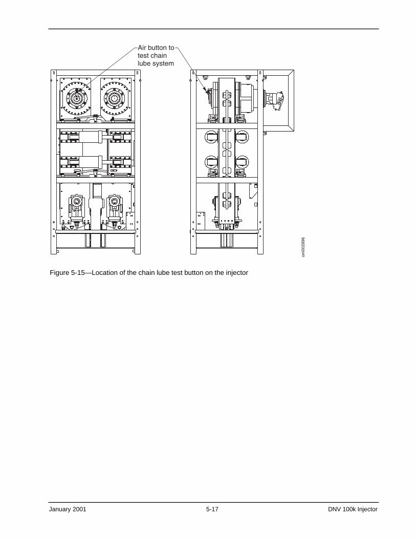
10. Function-test the chain lubricator by tripping the air switch located onthe gearbox housing. Verify that the system is delivering oil to the rollersof each gripper-block chain and each roller-bearing chain (Figure 5-15,Page 5-17).
11. Drain any water from both of the air filter/regulators on the chain-lubricator pump air lines (Figure 5-16, Page 5-18).
12. Check the fluid level in the reservoir for the hand pump/Haskel pumpthat energizes the injector connector. Add hydraulic fluid, if needed (PartNo. 70.30886) (Figure 5-17, Page 5-19).
Figure 5-11—Location of grease fitting on gripper-chain drive
om00
3494

January 2001 5-14 DNV 100k Injector
Figure 5-12—Location of grease fitting on linear-beam chain sprockets
om00
3494
b

January 2001 5-15 DNV 100k Injector
Figure 5-13—Location of grease fittings on gripper-chain tension adjustments
om00
2042

January 2001 5-16 DNV 100k Injector
Figure 5-14—Location of grease fittings on the hydraulic gripper cylinders andlinear-beam chain sprockets
om00
2041
January 2001 5-17 DNV 100k Injector
Figure 5-15—Location of the chain lube test button on the injector
om00
2896

January 2001 5-18 DNV 100k Injector
Figure 5-16—Location of drain valves on compressed air filter for chain lubricator
om00
2851

January 2001 5-19 DNV 100k Injector
Figure 5-17—Location of fill point on hydraulic fluid reservoir for hand pumpom
0028
52
13. Precharge pressure should be set to approximately 1/3 of the anticipatedoperating pressure. If the pressure needs to be changed, use the follow-ing procedure.
• Vent the hydraulic fluid back to the tank by opening the bleed valveon the bottom of the accumulator (Figure 5-18, Page 5-20)
• Use a gas charge kit (Part No. 130.17415) to measure the gaspressure.
• Use only nitrogen gas to recharge the accumulator. Recharge to thecorrect pressure.
• Record the precharge pressure on the checklist provided.

January 2001 5-20 DNV 100k Injector
Figure 5-18—Location of injector bleed valve
om00
3488
Every 6 MonthsUsing the 6-Month Checklist, perform the following inspection and maintenanceprocedures every 6 months.
1. Replace all three counterbalance valves. Two 10:1 valves are located onthe front of each counterbalance valve block, and one 5:1 valve islocated at the rear of the out-hole counterbalance valve-block. A plug islocated at the rear of the in-hole counterbalance valve-block.
a. Disconnect the 1 1/2-in. drive lines from the injector bulkhead.
b. Use a container to collect any spilled hydraulic fluid.
c. Using a hammer-wrench that fits the valve, loosen and gentlyremove the valve.
January 2001 5-21 DNV 100k Injector
d. Inspect the valve cavity for contamination. If contamination exists,clean the cavity.
e. Before installing the new counterbalance valve, coat the O-ringsalong the valve with a thin film of lubrication.
f. Gently install the new valve, taking care not to pinch the O-ring.
g. Repeat Steps a through f until all three valves are replaced.
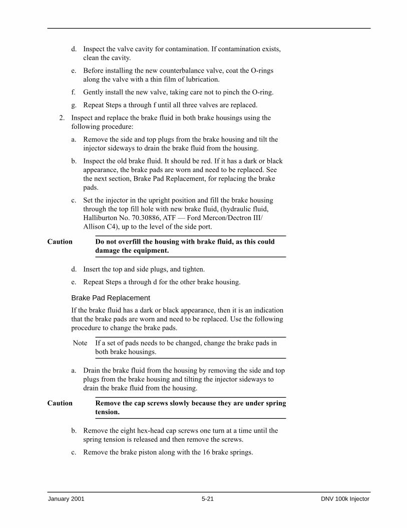
2. Inspect and replace the brake fluid in both brake housings using thefollowing procedure:
a. Remove the side and top plugs from the brake housing and tilt theinjector sideways to drain the brake fluid from the housing.
b. Inspect the old brake fluid. It should be red. If it has a dark or blackappearance, the brake pads are worn and need to be replaced. Seethe next section, Brake Pad Replacement, for replacing the brakepads.
c. Set the injector in the upright position and fill the brake housingthrough the top fill hole with new brake fluid, (hydraulic fluid,Halliburton No. 70.30886, ATF — Ford Mercon/Dectron III/Allison C4), up to the level of the side port.
Caution Do not overfill the housing with brake fluid, as this coulddamage the equipment.
d. Insert the top and side plugs, and tighten.
e. Repeat Steps a through d for the other brake housing.
Brake Pad Replacement
If the brake fluid has a dark or black appearance, then it is an indicationthat the brake pads are worn and need to be replaced. Use the followingprocedure to change the brake pads.
Note If a set of pads needs to be changed, change the brake pads inboth brake housings.
a. Drain the brake fluid from the housing by removing the side and topplugs from the brake housing and tilting the injector sideways todrain the brake fluid from the housing.
Caution Remove the cap screws slowly because they are under springtension.
b. Remove the eight hex-head cap screws one turn at a time until thespring tension is released and then remove the screws.
c. Remove the brake piston along with the 16 brake springs.

January 2001 5-22 DNV 100k Injector
d. Slide both the friction and the divider discs out.
e. Slide the brake hub shaft along with the ball bearings out.
f. Discard the old O-rings and the oil seal.
g. Use planetary brake repair kit, Lantec No. PMB180-60, SAP No.101215763, to replace discarded parts.
h. Set the injector in the upright position and fill the brake housingthrough the top fill hole with new brake fluid, (hydraulic fluid,Halliburton No. 70.30886, ATF — Ford Mercon/Dectron III/Allison C4), up to the level of the side port.
Caution Do not overfill the housing with brake fluid, as this coulddamage the equipment.
i. Insert top and side plugs and tighten.
3. Change the two hydraulic fluid filters on the inlet connections to theinjector drive motors (Figure 5-19).
Figure 5-19—Hydraulic fluid filters for injector drive motors
om00
3523

January 2001 5-23 DNV 100k Injector
Every 12 MonthsUsing the annual checklist, perform the following inspection and maintenanceonce a year. Figure 5-20 (Page 5-24) shows specific items to be maintained orinspected annually.
1. Inspect the tubing guide and injector. If necessary, clean them using thefollowing procedures:
a. Clean the tubing guide and injector with fresh water and detergentor a steam cleaner. Clean the gripper block grooves.
Important Remove any corrosive elements to which the unit may havebeen exposed. Corrosion is a primary cause of prematureequipment deterioration.
Caution Do not steam-clean the chains. Internal rust and corrosionwill result, causing premature failure. The chains are dippedin an oil bath at the factory and can never be completelyrelubricated internally while on the injector.
b. Although the chains were not cleaned, after cleaning the injector,immediately apply penetrating oil (Part No. 101215642) to allchains, and then spin them.
c. Apply the proper chain lubricant according to Table 5-1.
d. Spin the chains again. The oil should penetrate the interior movingparts of the roller chain assemblies. Verify that both sets of gripperchains and linear-beam chains are thoroughly saturated with thechain lubricant.
e. Use multipurpose grease to lubricate both the mounting tangs(Figure 5-4, Page 5-7) at the base of each linear-beam assemblyand the bellcrank mechanism’s roller surfaces (Figure 5-5, Page 5-8).
2. Examine all hydraulic components and connections for leaks.
3. Ensure that all leveling legs are engaged in the outer frame and that theyare secured to the mounts on the lift frame with the appropriate pins.
4. Examine the gripper chains and the linear-beam roller chains for correctchain tension and sprocket alignment. Refer to Adjusting the Tension ofthe Gripper Chain (Page 5-40) for detailed instructions.
Temperature Lubricant Part No.Below 10°F (-12°C) 101215641
Below 50°F (10°C) 101215642
Above 50°F (10°C) 1000005556
Table 5-1—Selecting the Proper Chain Lubricant

January 2001 5-24 DNV 100k Injector
Figure 5-20—Location of annual maintenance items on the injector
om00
2736
Important Chain tension is correct when the chain is snug, with only aslight dip in the center between supports. It should be similar tothe tension on a bicycle or chainsaw chain.
5. Check the sight gauge on the lube oil reservoir (Figure 5-6, Page5-8) toensure that the lubricant level is sufficient. If necessary, add lubricantaccording to Table 1, Page 5-23.
6. Inspect the condition of the hoses and fittings on the gripper cylinderconnections. The wire reinforcement must not be visible through therubber jacket. The fittings should not be damaged or leaking.
Important Always check the connections carefully. The failure of oneconnection or hose could result in a loss of gripper pressure.
7. Inspect the gripper blocks for wear and damage and replace as needed.
Important Replace worn gripper blocks in complete sets. Do not mix wornand new gripper blocks on the same chain. Additionally, do notmix gripper block part numbers on the same chain assembly.

January 2001 5-25 DNV 100k Injector
8. Examine the position of the cotter pins on the pins that secure thesideplates on each connector link of the chains. Refer to Figure 5-7(Page 5-10) for the linear-beam chains and Figure 5-8 (Page 5-10) forthe gripper chains for proper cotter-pin orientation.
Caution Make sure the cotter pins are aligned with the links. Mis-aligned or rotated pins can be caused by the roller seizing oncorroded or galled pins. When this rotation occurs, the pin islikely to fracture rapidly, causing the chain to break. Referto Maintenance Procedures starting on Page 5-27 for repairinformation.
9. After inspecting the chains, lockout the system, remove the protectiveguards, and measure the chain elongation. The baseline dimension forNo. 100 linear chains over a length of 10 links (11 pins) is 12.50 in.
Important The maximum allowable linear-chain elongation measured over10 links (11 pins) is 12.875 in. (Figure 5-9, Page 5-11). Replacelinear chains that have stretched beyond this point.
10. Measure the length across six links (seven pins) of gripper chain. If thelength is greater than 15.45 in., immediately replace the chain (SeeFigure 5-10, Page 5-12). Record the length on the checklist provided.Refer to Page 5-31 for information about replacing the gripper chain.
Important Replace the chain when elongation exceeds 15.45 in. Continuedgripper chain use past the fatigue point violates Halliburton CTpractice. Do not remove links or install spacers to extend chainlife.
11. Verify that the bellcrank mechanism is not binding. Lubricate thesurfaces of the mechanism if necessary.
12. Check the condition of the load pins. Make sure the wiring is notdamaged.
13. Using a grease gun, lubricate the following locations with multipurposegrease:
• gripper-chain and roller-chain sprocket bearings at each end of thethe linear beam (Figures 5-11 and 5-12, Pages 5-13 and 5-14)
• chain tensioner take-up bearings at the base of each linear beam(Figure 5-13, Page 5-15)
• rod-end bearings on the hydraulic gripper cylinders and linear-beamchain sprockets (Figure 5-14, Page 5-16)
14. Function-test the chain lubricator by tripping the air button located onthe gearbox housing. Verify that the system is delivering oil to therollers of each gripper-block chain and each roller-bearing chain (Figure5-15, Page 5-17).

January 2001 5-26 DNV 100k Injector
15. Drain any water from both of the air filters/regulators on the chainlubricator pump air lines (Figure 5-16, Page 5-18).
16. Check the fluid level in the reservoir for the hand pump/Haskel pumpthat energizes the injector connector. Add hydraulic fluid, if needed(Part No. 70.30886) (Figure 5-17, Page 5-19).
17. Precharge pressure should be set to approximately 1/3 of the anticipatedoperating pressure. If the pressure needs to be changed, use the follow-ing procedure:
• Vent the hydraulic fluid back to the tank by opening the bleedvalve on the bottom of the accumulator (Figure 5-18, Page 5-20).
• Use a gas charge kit (Part No. 130.17415) to measure the gaspressure.
• Use only nitrogen gas to recharge the accumulator. Recharge to thecorrect pressure.
• Record the precharge pressure on the checklist provided.
18. Drain the lubricant from each gearbox. Examine the drained fluid formetal particles and other indications that the lubricant is breaking down.With the gearbox axis level and the side port rotated to horizontal, fillthe gearbox with lubricant until the side port overflows (approximately2 gal in each gearbox). To prevent the reducer gear from overheating, donot overfill. Use the correct gear lubricant according to Table 5-2.
19. Check the vent ports on top of gear boxes to ensure that they are operat-ing properly and are not damaged, as this could allow moisture to enterthe gearbox.
20. Inspect the structural components of the frame, including all membersand welds, and the four pins at the top of the outer frame that are used toattach the lift eyes or tubing guide. To repair a crack in the welds, grindthe crack and weld it according to Halliburton Weld Specification70.79967. Document these repairs in the DNV (Det Norske Veritas) databook.
Temperature Lubricant Part No.50°F to 122°F (10°C to 50°C) 996.07893
32°F to 70°F (0°C to 21°C) 101215641
-5°F to 50°F (-21°C to 10°C) 101215642
Table 5-2—Gear Lubricant Recommendations