DMIC FILE COPY - DTIC
262
DMIC FILE COPY wC 'm 1l% N TI DW!313rON STAw .A Appzavod fcr PubaW Diatizu two="ns
-
Upload
khangminh22 -
Category
Documents
-
view
0 -
download
0
Transcript of DMIC FILE COPY - DTIC

DMIC FILE COPY
wC'm
1l%
N
TI
DW!313rON STAw .AAppzavod fcr PubaW
Diatizu two="ns

Federal Aviation A ainistrationU.S. Department of Transportation
Second Annual International Conferenceon
Aging AircraftAccesion For
NTIS CRA&oTIC TAB 0IJ anlo -. ed
i ~.)usI)h: ci +,
01st: 1bution I
Dist: '... /or
October 3-5, 1989
Grand BallroomMarriott Inner Harbor Hotel
Baltimore, Maryland
90 06 11 154
L _ d i._ ..

Technical Report Documentation Page
I, Report No. J ,J 2. GN...... Ac...... o No. 3. Rec .p nt's Catalog No.
DOT/FAA/CT-89/35
4. Ttle and Subttle S. Report Date
February 19902nd Annual International Conference on 6. Performng Organaton Cod.
Aging Aircraft Proceedings
S. Performing Organ,at.on Report No.
7. Author' $)
9. Performing Organilrton Name entd Addrles 10. Work Unt No. (TRAIS)
Flight Safety Foundation 11. Contract o, G ant No.
2200 Wilson Blvd., Suite 500 DTGAL1014-89-5-01Arlington, VA 22201 13. Type of Report and Period Co..ed
12. Sponsr.ng Agency Name and Address Proceedings
Department of Transportation October 3-5, 1989Federal Aviation Administration, Technical Center 14. Sponsoring Agency Code
Atlantic City International Airport, NJ 08405 ACD-200
15. Supplementary Notes
16. Abstract
This document contains the formal presentations made at the 2nd
Annual International Conference on Aging Aircraft. It includes statusreports in the areas of transport and commuter aircraft certification,maintenance, research and development, the ATA/AIA airworthinessassurance task force and efforts by NASA. Also included are detailedpresentations on the research and development efforts underway andplanned in the areas of structural fatigue, loads, corrosion,nondestructive testing/inspection and human factors. I.., - . -
17, Key Worde 1. Oistribution Statement
-., Aging Aircraft This document is available to the public
Airworthiness - through the National Technical InformationResearch and Development - . Service, Springfield, Virginia 22161
19. Security Clseif. (of this report) 20. Security Claesif. (of thil page) 21. No. of Peges 22. Price
Unclassified Unclassified 254
Ferm DOT F 1700.7 (8-72) Reproduction of completed page authorized

EDITORIAL NOTE
The majority of the papers presented in this proceeding were transcribedfrom audio tapes recorded during the conference. An attempt has beenmade to retain the sense of a conversational tone. In this type of presen-tation there tends to bea duplication in text and illustrations. To correct forthis feature, the editors deleted some illustrations that were better dis-cussed in the text. Conversely, certain textual changes were made in theseinstances where the use of the illustration itself was more appropriate.
Artwork used in this proceeding is the best available. In several instances,the original photographs or slides were not available or were of such aquality that they could not be used. In these cases the text was edited tocompensate.
NOTICE
This document is disseminated under the sponsorship of the Departmentof Transportation in the interest of information exchange. The UnitedStates Government assumes no liability for its contents or use thereof.
NOTICE
The United States Government does nc i ei _Irse products or manufacturers.Trade or manufacturers' names appear !' -in solely because they are con-sidered essential to the object of this report.
I

Table of Contents
OPENING SESSION
Introductory Remarks, Conference Chairman, Thomas E. McSweeny,Deputy Director, Aircraft Certification Service, FAA ............................................ 1
Welcome to Attendees, Joseph M. Del Balzo, Executive Directorfor System Developm ent, FA A .................................................................................. 2
Keynote Address, The Honorable James L. Oberstar, Chairman, HouseSubcommittee on Aviation, U.S. House of Representatives .................................. 5
Conference Overview, Anthony J. Broderick, Acting Executive Directorfor Regulatory Standards and Compliance, FAA .................................................. 9
STATUS REPORTS
Transport Aircraft CertificationLeroy A. Keith, Manager, Transport Airplane Directorate,FAA N orthw est M ountain Region .......................................................................... 12
Commuter Aircraft CertificationBarry D. Clements, Manager, Small Airplane Directorate,FA A C entral R egion ................................................................................................... 19
MaintenanceRaymond E. Ramakis, Assistant Director for Special Programs,Flight Standards Service, FAA Headquarters ....................................................... 24
Research and DevelopmentDick Johnson, Aging Aircraft Research Program Manager,FA A Technical C enter .............................................................................................. 30
ATA/AIA Airworthiness Assurance Task ForceClyde R. Kizer, Vice President, Engineering and Maintenance, ATA ............... 36
NASA Aging Aircraft EffortsDaniel R. Mulville, Deputy Director, Materials and Structures Division,N A SA H ead quarters ................................................................................................. 47

SESSION I: STRUCTURAL FATIGUE
Chairman, Thomas Swift, FAA National Resource Specialist .................................. 60
Continuing Airworthiness of Aging Jet TransportsUlf G. Goranson, Ph.D., Manager, Damage Tolerance Technology,Boeing Commercial Airplane Company ............................................................. 61
Multiple Site DamagePin Tong, Ph.D., Research and Special Programs Administrator,Transportation Systems Center, U.S. Department of Transportation .............. 90
Proof Testing of Pressure CabinsJ. Ben de Jonge, Netherlands National Aerospace Laboratory (NLR) .............. 99
SESSION II: LOADS
Chairman, Terence J. Barnes, FAA National Resource Specialist .............................. 105
Flight Load Data CollectionThomas DeFiore, Flight Loads Program Manager, FAA Technical Center ...... 110
Structures TechnologyNorman L. Crabill, Aerospace Technologist, Eagle Engineering ...................... 117
Flight LoadsJ. Ben de Jonge, Netherlands National Aerospace Laboratory (NLR) ................ 133
SPECIAL PRESENTATION
The Responsibilities of FAA, the Manufacturers and the Airlinesfor the Continuing Safety of Aging Aircraft
William R. Hendricks, FAA Director of Accident Investigations ...................... 142
SESSION III: CORROSION
Chairman, John J. De Luccia, Manager, Aerospace Materiais Division,N aval A ir Developm ent Center ............................................................................ 150
CorrosionJ. A. Marceau, Principal Engineer, Boeing Commercial Airplanes .................... 153
Corrosion ControlCharles Hegedus, Team Leader, Organic Coatings,Aerospace Materials Division, Naval Air Development Center .......................... 158
Corrosion ControlRobert DeRosa, Standards and Systems Division, United Airlines .................... 166
SESSION IV: NDE/NDI
Chairman, Stephen N. Bobo, NDI Specialist, Transportation Systems Center,U .S. Departm ent of Transportation ....................................................................... 174
Thermographic Inspection TechniquesWilliam Winfree, Advanced Sensors Group, NASA Langley Research ............ 184
Nondestructive Testing of Aging AircraftDonald J. Hagemaier, NDE Group Leader, Douglas Aircraft Co1tpany .......... 186
ATA/NDT ForumJames L. Morgan, Manager, Inspection/NDT, Trans World Airlines ................ 199
NDT EvaluationBruce A. Kotzian, FAA Aviation Safety Inspector-Maintenance ........................ 202
SESSION V: HUMAN FACTORS
Chairman, William T. Shepherd, Ph.D., Manager, FAA Biomedicaland Behavioral Science Branch .............................................................................. 204
The Vigilance PhenomenonEarl L. Wiener, Ph.D., Professor of Management Science,U niversity of M iam i, Florida .................................................................................. 206
Industrial InspectionColin G. Drury, Ph.D., The Center for Industrial Effectiveness,State U niversity of N ew York, Buffalo .................................................................. 213
Allies in Maintenance: The Impact of Organizational Roleson Maintenance ProgramsJames C. Taylor, Ph.D., Professor of Human Factors,U niversity of Southern California ......................................................................... 221

GUEST SPEAKER
The Honorable Tom Lewis, Congressman, State of FloridaSpeech presented by Dr. James C. Greene, Science Consultant,House Committee on Science, Space and Technology ............................................ 226
SUMMARY REMARKS
Conference Chairman, Thomas E. McSweeny, Deputy Director,A ircraft Certification Service, FAA ..................................................................................... 229
REG ISTERED A TTEN D EES ................................................................................................ 232

Introductory Remarks
THOMAS E. MCSWEENY, Conference Chairman
Deputy Director, Aircraft Certification Service, FAA
I want to welcome you all to the 2nd An- on with the business of ensuring a safe trans-nual International Conference on Aging Air- portation system as the fleet ages.planes. Many of you I'msurewereat last year's Much has been done since the last confer-conference. It was intended to be a general in- ence. In this conference we'll summarize theformation meeting where all in attendance could work accomplished or the work underway.share their experiences and give their views on Over the last year the FAA and industry havethe aging airplane issue and also what they seen many examples of aging airplanes, air-thought were some of the solutions at the time. planes that were not properly maintained, and
We had many views, some consensus on improper repairs that have compromised thethe part of those present, and we summarized structural integrity of the airplane's structure.all the material in the proceedings which we've We all need to look at the operations withinmade available through the National Technical our countries and within our airlines to ensureInformation Service in Springfield, Virginia, if we do not have any problems in our fleets likeanybody wants to obtain a copy. those shown.
Last yearat this time the FAAand industry With that short introduction, I would likewere trying to scope the problem, identify to now introduce Mr. Del Balzo. He is thesome short- and long-term solutions, and get FAA's Executive Director for System Develop-
ment.
.1

Welcome to Attendees
JOSEPH M. DEL BALZO
Executive Director for System Development, FAA
I will start by telling you that Administra- change views, exchange information and totor Busey is unable to be with us this morning. form a program to solve a problem. We didn'tHe has another commitment. He's asked me to do it to point fingers, and we continue thatextend his greetings to all of you, as well as his approach today. The world has really changed.regrets that he could not be here to attend this I don't know your views, but most of you,very important conference. I suspect, were at last year's conference. I think
I will also tell you that he believes that the it was a success. I think a lot of good thingssubjectofagingaircraftisextremelyimportant. happened as a result of that conference. AnWhat I have heard him talk about so many industry task force was initiated in August oftimes is how important it is for us to plan for the 1988. An FAA program review research initia-long term. Thedevelopmentandapplicationof tion was conducted in October, 1988 and thenew technologies is one way. Getting more Aviation Safety Research Act was passed inmileage out of the existing fleet is another way November. An Industry Research and Devel-to achieve that goal. Improved maintenance opment Task Force unit was formed in Marchtechnology, better quality control and highly of 1989 and an FAA Aging Aircraft Researchtrained inspectors are more keys to keeping Program Plan was completed in May of thisolder aircraft aloft. year. In a lot of areas, research has already
I couldn't help but be struck by the pictures begun.that Tom showed in the beginning. Not too We come to this second annual conferencelong ago we would not have had the courage to with a different agenda. We come with severalcome together to talk about an aging aircraft objectives. The first is to review the agency'sproblem. We certainly wouldn't have had the role in maintaining the high level of aviationcourage to do it out in the open. safety, especially in regard to aging transport
Certainly the world has changed. We came aircraft, those aircraft operating beyond thetogether last year for our first conference, and original economic design life approved by theas Tom McSweeny said, it was more to ex- FAA.
2

Joseph M. Del Balzo
A second objective is to discuss the prog- capacity, raise speed, and reduce crew work-ress that we in the industry have made in load. That's the good news.resolving the problems associated with these The bad news is that the advances haveolder aircraft that were first discussed at last brought-with them a large number of questionyear's conference. marks, and a large number of challenges that
Finally, we are here to listen to what the we must face together as an industry. There'sinternational aviation community thinks, and no question that technology has provided thehas done, about older aircraft since last year's aviation industry with the benefits that haveconference, and to hear its opinions about FAA's enabled air transportation to become strongnational aging aircraft program. What are we andviableand, yes, a safe industry worldwide.doing right? What have we done wrong? What But it is also the FAA's job to mandate thatshould we be doing more of? What changes we use the many benefits offered by our fastshould we make? moving technology to ensure that the safety
I think it goes without saying -and I speak and viability of the aviation industry continue.for FAA Administrator Busey, and Secretary of To meet these challenges, the FAA has es-Transportation Skinner as well - that we are tablished a very aggressive national aging air-here this week to listen. What we did last year craft research program. We developed andwas good and we'll do it again this year. We not published a multiyear program plan that in-only welcome all the inputs we will receive this cludes R&D projects and operational tasks. Inweek; we consider them the most important developing the plan, we listened to you, thebenefit that we will get from this conference, a aviation industry. We listened to you espe-series that will and must continue. cially carefully at last year's aging aircraft
I am reminded of what the manager, in the conference, and we liked a lot of what webaseball movie "Bull Durham," said after he heard. Those suggestions that still soundedlost the game. "Sometimes you win, some- good after scrutiny by experts we freely incor-times you lose, sometimes you get rained out." porated into the plan.If I were to add another comment, it would be, It was a good plan when we issued it. I"But in no case do you ever give up the quest." think it's a good plan now. But the worldThat's why we are here. We will not give up the changes and the plan will change, based on thequest to solve the problem of aging aircraft, discussions that take place this week.until it is truly solved. The short-term objectives of our national
The history of air transportation in the United aircraft aging program focus on the identifica-States during the last decade is a good news/ tion, definition, and resolution of immediatebad news story. The good news is that the problems. These are near-term issues associ-demand and traffic has grown at an unparal- ated with in-service aircraft. Meanwhile, theleled rate; and to meet the demands, the air- research side of the agency has started formu-lines have used their transport fleets beyond lating the multiyear R&D program.the aircraft's original economic design life. The longer term objectives of the plan con-
The bad news is that we are seeing prob- centrate on those issues and potential prob-lems not encountered before. These are the lems that apply to new and future aircraft. Weproblems of aging: stress, corrosion, high-cycle expect your inputs at this year's conference, asfailure, low-cycle fatigue, and their effects at last year's, to lead to changes in both theindividually and together on the safe opera- short- and long-term objectives of our plan.tions of transport aircraft. The question now is, how are we doing?
Another major contributor to the good news/ And that's what we hope to hear this week. Ibad news story is technology itself. Over the believe that we have made significant progresspast decade, technology has provided the avia- during the past 12 months. You will hear intion industry with a host of advanced materi- more detail about our progress on both the op-als, manufacturing methods, and designs that erational and research fronts during theconfer-save weight, reduce fuel consumption, increase ence.
3

Second Annual International Conference on Aging Aircraft
Following Tony Broderick's overview, Le- District of Minnesota, the Honorable James L.roy Keith, Manager of the Aircraft Certification Oberstar. Jim Oberstar is somewhat of an enigma.Division of FAA's Northwest Mountain Re- All my life I've wanted to call a Congressmangion, will present us with a status report on an enigma, and this morning I get that chance.transport certification. He is the son of a miner and he believes that
Barry Clements, who is the Manager of the public works projects have great potential asSmall Airplane Directorate from the Central job creators, but yet he's not the typical HouseRegion, will give you a status report on com- Public Works Committee member who believesmuter aircraft certification. in shoveling dirt first and thinking about policy
Ray Ramakis, who is Manager in the Air- implications later. In fact, in Congressmancraft Maintenance Division at FAA Headquar- Oberstar's case, our observations say it is justters, will updateus on the progress made in the the opposite.maintenance area. He has the instincts of a scholar and re-
Dick Johnson, who is the Aging Aircraft former, and he's legendary on Capitol Hill forProgram Manager at the FAA Technical Cen- his insightful and in-depth questioning of wit-ter, will follow with a report on the agency's nesses who appear before him.R&D efforts, focused on older transport air- As the taxpayer and traveler's interest incraft. aviation has grown, Congressman Oberstar's
Your challenge for this week, for all of you, chairmanship of the House Subcommittee onfor all of us, is to focus on what we should be Aviation has taken on greater importance anddoing together to improve the safety of aging significance. He is a distinguished leader in theairplanes. We look forward to the closeout dis- field of aviation. We are fortunate to have himcussions on Thursday afternoon. with us today. Please welcome Congressman
As I close, it is with great pleasure that I Oberstar.introduce the Congressman from the Eighth
4

Keynote Address
THE HONORABLE JAMES L. OBERSTAR
Chairman, House Subcommittee on AviationU. S. House of Representatives
Many years ago, Lyndon Johnson, long be- bespectacled, farmer approached me. And hefore he was President, was glowingly intro- said, "Say, Jimmy, you know, you better keepduced. As he got to the microphone, he said, "I on those guys about those old aircraft. By God,wish my parents had been here tu hear that you better make them fix them because I don'tintroduction. My father would have loved it, know if it's safe to fly anymore."and my mother would have believed it." Also there was a visiting group of farmers
Good morning. It was this past mid-Au- from Sweden on an exchange program. Mygust, and, as I do almost every year, I was at the friends asked me to come into the bus and talkAlmerlund Threshing Festival in the Swedish to the farmers. And you know, the first ques-part of my district, farm country, dairy coun- tion from those Swedes was, "Is it safe to fly?"try. I was down there for the annual display of And so it went for over an hour. I didn't getfarm equipment; pieces of machinery, some of a question about dairy price supports. Fourwhich have been running for well over 100 years earlier I went not to Almerlund, but toyears, meticulously cared for by farmers and Karl Lasterdase, which is in the same regionshown off to their friends and neighbors. I had with all those Swedes, and I remember thisboned up for what I knew was going to be a day young fellow by the name of Ernie Lund corn-of grilling about dairy price supports, the coming ing up. After we had a long discussion about50-cent cut in the price support for dairy farm- dairy price supports, he said, "Boy, I sure amers, regional marketing orders, the price sup- glad to hear you talking about dairy becauseallport for com and prices on soybeans, the drought we've been seeing you on television is aboutand the new legislation that several of us from flying and airplanes. We thought you'd forgotdairy country had authored to help dairy about us dairy farmers, wondering why youfarmers. spending so much time on aviation."
So I was all prepared when I walked down Well, today they know why. Today theyto the grounds and this big, burly, overalled, care and today they're worried. You and all of
5

Second Annual International Conference on Aging Aircraft
us are gathered here in the earnest purpose of the haunting reality that something terribleputting Ernie Lund's mind at rest, his fears to had gone wrong in all of our thought processesrest, and keeping aviation the safest mode of and our calculations about the way in whichtravel for all humankind, aircraft are built, flown, and maintained.
Over a year ago, when I addressed the first And there was a determination to make aaging aircraft conference, I expressed hope it real difference, and you have done so.wouldn't be the last. And I congratulate Secre- What concerned me then at the outset oftary Skinner and Administrator Busey, at the that conference was not that there wasn't ahelm of FAA, for strong support of this proc- tracking system for aging aircraft; there was.ess, but I particularly want to congratulate It's not that the system wasn't used; it was.Tony Broderick who has made it a cause; Tom What concerned me was that all the right stepsMcSweeny who has carried the heavy lifting on were taken, but for Flight Attendant Clarabellthis whole process; and for all the dedicated Lansing and for the injured and frightenedprofessionals at FAA and those in the industry passengers aboard Aloha Flight 243, the sys-who have really bent every effort, every idea, tem failed. For Clarabell Lansing, the failureevery energy to the multifaceted issues sur- was fatal.rounding aging aircraft, continuing what was We must keep that in mind because thatso brilliantly begun a year ago, courageously I conference was a demarcation point, a land-must say, by Alan McArtor, who did so in the mark in aviation history. A fundamental shiftpurpose that this effort would persist. It has, it in maintenance philosophy emerged as a prod-will and, as Joe Del Balzo just said, it must. And uct of that conference, and we saw a shift fromit must bring about change, change th; is the old approach of inspect and repair to a newdramatic, ever renewing and ever self-critiqu- philosophy of terminate and replace at specificing. The graying of America's civil aviation intervals. And in this mode, airline mainte-fleet has changed forever not just the way nance for high-time aircraft will no longer waitaircraft maintenance is conducted, but more for smallcracks to develop into large problems.importantly, it has radically changed our think- No longer will corrosion, fatigue, and multisiteing about maintenance, our philosophy if you damage have to be discovered by an airlinewill, about the conduct of maintenance, inspector often working late at night and al-
As the nation's air traffic continues to grow, ways subject to the limitations of the naked eye,aircraft that were expected to be retired at the fatigue and other human factors.end of their so-called economic design lives are The purpose of this conference, then, is tobeing kept in service, and will continue to be assess how far collectively, civil aviation - thekept in service, long beyond that point in order manufacturers, the airlines, the FAA and itsto meet the increasing passenger demand. counterparts in other countries - has come
We had 461 million boardings last year. We with this new philosophy. How far have weexpect that number to double in the next dec- come in correcting the deficiencies and to vastlyade. Last year, 2,400 aircraft were more than 20 improve the performance of high-cycled air-years old. By the year 2000, projections are that craft, and most of all to reassure the travelingthat number will rise to 5,700. The aging air- public?craft phenomenon is at our doorstep for keeps. On balance, I can say after extensive hear-
The dramatic Aloha Airlines tragedy of ings on this subject and very close involvementApril 28, 1988, not only shocked FAA and the with the process that I am pleased and I amindustry, but galvanized both groups into some impressed with the actions that industry andsteps that are fairly radical for what historically government have taken and the decisive andhas been a rather slow-movingsector. My most purposeful way in which all have acted in re-vivid memories of that first aging aircraft con- sponse to this phenomenon.ference are the electricity that was in the air, the I congratulate the Boeing and Douglas work-sense of anticipation, the unswerving determi- ing groups on the thorough review they havenation to do something good and lasting under undertaken of thousands of service bulletins.
6

James L Oberstar
Additionally, there have been other short-term between major maintenance undertakings. Andobjectives. Many of them are underway and as aircraft increasingly are operated in a widerthey include the development of more effective range of climate conditions and are increas-corrosion prevention and control programs, a ingly operated at the upper end of their eco-review of existing maintenance plans and an nomic design life, we have to change ourmind-assessment of supplemental structural inspec- set, and admit that we are operating at thetion programs. All of those actions are neces- threshold of knowledge and experience aboutsary to ensure fleet airworthiness, the aging aircraft phenomenon, that we are in
But I believe we need to go further. Last uncharted territory.week, aviation industry representatives told I have come to the conclusion that we needmy subcommittee on aging aircraft that with toraisearedflag, oratleastacautionflag, attheproper inspection and maintenance, aircraft high cycle point in an aircraft's life span. And Ican be operated virtually indefinitely. Maybe propose the establishment by the FAA of athey're right; but what if they are wrong? comprehensive, high-cycle, airworthiness audit
As we proceed through the process, let's and review procedure for aging aircraft. I pro-keep one sobering statistic in mind. The Na- pose that the audit require aircraft operators totional Transportation Safety Board data show justify the continued operation of the aircraft asthat from 1970 through 1985, metal fatigue or it approaches the high end of its design life.corrosion, in some cases both, were involved in A higher burden of proof of airworthiness77 out of 579 aviation incidents. Our goal should would be exacted of the operator at this stagebe to reduce that figure to a number approach- than for other previous maintenance actions.ing zero. Both the carrier and the FAA will have to meet
To reach that goal, all the recommenda- to review maintenance of the aircraft through-tions of the Boeing and Douglas groups must out its history, with emphasis on the agingbe rigorously implemented by the carriers, process: terminating actions; corrosion preven-domestic and foreign alike. That implementa- tion and control procedures; metal fatigue; thetion must be vigorously inspected and en- aircraft's total operating environment, where itforced by the FAA and its foreign civil aviation customarily and ordinarily operates; andcounterparts. There must be more hands-on damage tolerance. All the other stresses toinspection of aircraft by the FAA and foreign which aircraft are subjected would, in thisauthorities. We cannot afford, as in the past, a process, be rigorously and critically evaluated.rather substantial reliance upon paperwork This review would be supplemented by areview of maintenance operations. hands-on inspection by the airworthiness au-
Government and industry - I think this is thority. And if at the end of that process thevery important - must do a much better job of airworthiness audit authority concludes thatcollecting and analyzing trend data on aircraft the aircraft is fit to continue safe operation, anmaintenance so we can know how to anticipate appropriate notification can be issued and theemerging problems and how most effectively aircraft returned to service.to allocate our resources. What I envision and propose is a holistic,
Industry and government both need a com- not a segmented, piecemeal process applied topletely redesigned mindset about the longev- the continuing airworthiness and fitness op-ity of aircraft. The manufacturer's assumptions eration. I am advocating an approach in whichand projections about economic design life need the aging aircraft is scrutinized as a system, notto be reexamined, especially in light of how as pieces of a whole, and not as a collection ofcertain carriers accumulate flight cycles. For replaceable parts.example, Aloha accumulated flight cycles at Only then can we genuinely assure thetwice the rate for which Boeing designed the flying public that the nation's air transport737. system is operating not at the margin, not at
D check intervals need to be shortened as only the safety we can afford, but at the highestaircraft accumulate higher numbers of cycles possible level of safety.
7

Second Annual International Conference on Aging Aircraft
Civil aviation's biggest safety problem is unforgiving environment. Wecannot relax ourwhat has become known as the human factor. vigilance.Making decisions about a series of mechanical As we proceed in this process and work to-fixes and modifications to aircraft is much less gether, I want to assure you that my colleaguesdifficult than fully understanding why human in the congress are concerned about this issuebeings do not do what they are supposed to do and ready to do whatever is necessary andor why they fail to perform as we expect them devote whatever resources are required toto perform. address it effectively. I assure you also that the
There are a number of human performance traveling public, while not yet white-knuckled,questions that we need to address and I hope is serious and concerned and has a lot at stakewill be addressed in the course of this or other riding on what you do, what you decide, andconferences. What can be done about the fact what actions you take asaconsequence of thesethat rivet inspection is boring, tedious, mind- conferences.bending work, susceptible to human error? In conclusion, I am reminded so often, as IHow do we ensure that the means established deal with this issue of aviation, of Thorntonto communicate with each other are in fact Wilder's quest for truth and for answers to theeffective, and that the right information is find- age-old problem of death. He wrote of theing its way to the right people at the right time? bridge at San Louis Rey, and a tragic accident in
How do we know whether training of in- which five people fell into a chasm when thespectors and mechanics is all that it needs to be? bridge collapsed over a century-and-a-half ago.And how do we ensure that it will be? Brother Juniper, who happened upon a
All of these and other human factors are community where an annual remembrance wastough ones, difficult to attack because we are taking place, undertook to find the cause ofdealing with human beings who don't perform why those particular five people died at thataccording to mathematical models. But the particular time. And he said, either we live byFAA and the industry have to attack them with accident and die by accident, or we live by planthe same vigor that the task forces have ad- and die by plan.dressed to the other technological problems of Brother Juniper resolved to inquire into theaging aircraft. secret lives of those five persons to surmise the
Here there is no universe of documents to reason of their dying. At the conclusion of thatreview on performance history. We're dealing marvelous inquiry into human nature, he said,with people. We can't throw up our hands and "Some say that we shall never know, and thatsay they can't be dealt with; they can be, and to the gods we are like flies that boys kill on athey've got to be. We have to find answers to summer day. Some say, on the contrary, thatthe human dimension or we will not have done sparrows do not lose a feather that has not beenour job completely or well enough. brushed away by the finger of God."
The thinking here has to be just as bold and Let us not wait for philosophical interpreta-radical as it has been in other areas. Just be- tions, or prayer, or insight into lives lost, tocause we fixed the aircraft does not mean that unlock the secrets of aging aircraft and whatwe have fixed the problem of aging aircraft, best to do to prevent mysterious loss of life.and we won't have done so until we have dealt You are engaged in a great enterprise. Iwith the human factors. congratulate you. I wish you well in this en-
We have to remember that the aircraft, the deavor and will follow very closely the pro-flight crew and the passengers who ride those ceedings of this conference.aircraft all operate in an inherently hostile and Thank you for the privilege of being with
you this morning.
8

Conference Overview
ANTHONY J. BRODERICK
Acting Executive Director for Regulatory Standards and Compliance, FAA
Good morning, Mr. Chairman, ladies and need for better maintenance as airplanes age.gentlemen. This morning I would like to touch Those in attendance at this aging aircraft con-on some of the lessons we have learned so far ference a year ago heard many of the operatorsfrom our cooperative aging airplane efforts state that the majority of in-service failures areover the last year. I would also like to discuss a result of corrosion, prevention of which isactions that should be taken by airworthiness basically a maintenance function.authorities, manufacturers, and airlines around Since that conference, there have been manythe world. efforts on the part of the airlines to improve
Like most aviation issues, this is not one we maintenance as a whole, and corrosion controlface or can deal with alone. The FAA has initi- and prevention specifically.ated a program, as an integral part of our Multisitedamagedoes occurin service. It isoverall aging airplane program, for its inspec- hard to find, and itdoes reduce theability of thetors and engineers to visit operators while fuselage to tolerate in-service damage. We'veaging airplanes are undergoing major main- seen several instances of multisite damage ontenance. transport airplanes. While it had not progressed
This renewed emphasis on hands-on work to the point of becoming an imminent safetyhas enabled the FAA to gain better firsthand hazard some of that damage has been exten-knowledge of the condition of the aging fleet in sive and has obviously reduced the ability ofthe United States and the adequacy of opera- the airplane structure to accommodate the leveltors' maintenance efforts. of service damage which the original design
At the same time, the manufacturers have could withstand. Laboratory testing has alsointensified their programs of looking at aging confirmed the possibility of the occurrence ofaircraft under repair at airlines throughout the multisite damage in typical airplane structures.world. We have learned a number of lessons. Corrosion is more widespread than thought.Let me cite a few that strike us as significant. Programs must be adopted early in the life of
There appears to be more awareness of the an airplane to ensure continued safety, since as
9

Second Annual International Conference on Aging Aircraft
noted earlier, corrosion is the leading cause of protect their investments. Those requirementsin-service failures. will parallel very closely the programs recom-
As the FAA visits aging airplanes under in- mended by the manufacturers and, of course,spection, we are vigilant for corrosion and we mandatory aging airplane requirements thatsee it on a regular basis and in many areas not are issued by the cognizant airworthiness au-previously thought to be prone to corrosion. thority.The more cost-effective solution to the corro- Data have been obtained that show somesion problem is to adopt early programs to operators around the world are taking lesscontrol it, rather than replace or repair the than adequate care of aging airplanes. Thematerial after it corrodes. presentation by Tom McSweeny graphically
A good corrosion prevention and control described some examples. But don't think thatprogram must be one of the basic elements of it can't happen here. It could if we don't do ourany maintenance program. It is essential that job; but it shall not, because not one of us in thiscorrosion control not just be a secondary func- room can permit it to happen.tion performed when the opportunity presents In looking at aging airplanes, we discov-itself. Corrosion control should bea program of ered numerous cases of improper repairs thatits own, staged to coincide with other mainte- reduced the structural integrity and damagenance visits. tolerance capabilities of the basic airplane de-
In areas of the airplane where structural sign. In visits to U.S. carriers to evaluate agingstrength is important, where there is a high airplane maintenance, several cases were dis-probability of occurrence of cracking, and in- covered where the basic structural strengthspection is difficult, it is essential that modifica- and crack-stopping features of the design weretions or material replacement be accomplished compromised by a repair.as airplanes age. This is an essential element of More information needs to be provided bythe aging aircraft program. We can no longer the manufactuers regarding proper repair tech-rely on extensive, routine, boring and monoto- niques, and that guidance should be followednous inspections in areas that are critical to by all airlines.flight safety. A structure known to be prone to It appears clear that the international coop-the aging phenomenon must be replaced be- eration already evident in some of the agingfore it ages. airplane programs must be continued. Each of
The agingairplane problem is international us needs to draw on the lessons learned byin scope and requires the cooperation of all air- others. There must be a commitment, by thoseworthiness authorities and airlines in follow- in authority, to do several things:ing defined aging airplane programs includingmandatory airworthiness directives. 0 We must ensure that at the design stage, all
In countries that have adopted mandatory new airplanes adequately take into accountaging airplane requirements, we expect that the aging airplane phenomenon.more validation of service history and ade- * We must ensure that manufacturers of trans-quate maintenance will be required before bring- port airplanes prepare and revise supple-ing airplanes onto the register of that country mental structural inspection documents,or into service on its airlines, taking into account the lessons learned,
It is essential then, that airplanes moving and to be learned, from present and futurefrom country to country on leasing agreements, aging airplane programs.be maintained in accordance with recognized * We must ensure that all manufacturers ofand accepted standards; that maintenance rec- transport airplanes prepare a corrosionords and records of major modifications or al- control program for use by the operators.terations be complete. Mandatory action requiring adherence to
Future leasing agreements are likely to be this program should be considered by themuch more specific as to maintenance and cognizant airworthiness authority.inspection requirements as lessors attempt to * We must work together to review and rewrite
10

Anthony J. Broderick
the operators' maintenance and inspection assume other countries as well, stand ready toprograms so they are more in tune with the share their wealth of knowledge with air-aging airplane needs. We intend to require worthiness authorities and operators aroundall operators to have an approved corro- the world.sion control program modeled after the one In the past year, the airlines have donerecommended by the manufacturer. We much to improve the programs they are usingurge all other airworthiness authorities to to address these important safety issues. Theirconsider doing the same thing. efforts have been truly extraordinary.
" We must continue the work initiated in this This work of industry and governments, inpast year to ensure that a process exists a cooperative and nonadversarial environment,where service problems, structural failures has been a hallmark. We at FAA are proud ofand other significant events are reported to our part in the accomplishments of this jointthe airplane and engine manufacturer and effort. We pledge a continued dedication tomade available for others to benefit from. that spirit of cooperation.The current service difficulty report system I am delighted to see a continuation ofjust does not fill that bill. international interest in these important issues,
* Finally, we must continue to follow and co- as evidenced by the strong attendance here atoperate on worldwide aging airplane is- this meeting. I am particularly pleased to seesues in order to implement timely actions that we have sustained momentum on a broadand maintain the confidence of the travel- front and that theconference will cover in someing public, detail the areas of structure, loads, corrosion
and human factors.The FAA has committed its resources to All of us have an exciting opportunity to
these challenges. We stand ready to share ag- make a difference by applying our individualing airplane experiences with anyone. The manu- expertise to a variety of challenging technicalfacturers in the United States, and I would problems.
11
Transport Aircraft Certification
LEROY A. KEITH
Manager, Transport Airplane DirectorateFAA Northwest Mountain Region
Good morning, ladies and gentlemen. It's continued operational safety of all transportcertainly my pleasure and honor to address airplanes that have an FAA type certificate. Wesuch a distinguished group and to share with are responsible for the rulemaking for Part 25,you the status of all of the efforts that we have and for the certification of new or modifiedhad underway in the Transport Directorate in aircraft.the last 16 or 18 months, and to talk about some As Congressman Oberstar and Tony Brod-of the plans that we have underway. erick said, the tragic Aloha accident certainly
Before getting into the program, I would did refocus our attention on the aging airplanelike to just put in a little plug for our organiza- issue. What I want to cover today are basicallytion, the Transport Airplane Directorate. Lo- three things: what we did in the Transportcated in Seattle, I have a staff that handles all of Directorate immediately following Aloha; sec-the rulemaking activity concerning design rules ond, the accomplishments achieved in the lastfor transport airplanes. 18 months; and then finally, our plans for the
There is also an office in Seattle that deals future.primarily with Boeing airplanes. I have an Within hours after the Aloha accident, weoffice in Long Beach that deals with Douglas issued a precautionary telegraphic airworthinessand Lockheed airplanes, among a lot of other directive that limited the cabin pressure differ-things. That's where the transport activities are ential on those airplanes to a lower level, whilelocated, everybody went to work trying to understand
The staff in Seattle also deals with all of the the mechanics of that accident.imported transport airplanes that operate with Within a few days, we had issued anotherFAA type certificates. We're responsible for the immediately-adopted airworthiness directive
12

Leroy A. Keith
that did in fact require some inspections of spe- The task force is in fact reviewing five majorcific lap splices on the 737. In the meantime, in areas: (See Figure 1) The service bulletin re-the Transport Directorate, we sent people to view, which is pretty well completed, but isHawaii tosupport theNTSB investigation efforts. expanding to review all of the fatigue service
Those who stayed behind started asking bulletins that have been issued for these air-some fundamental questions about aging air- planes, use a criteria that I'll discuss shortly.craft and what assumptions we had made, and Corrosionprogram developmentisthemajorwhat philosophies we had used in certificating effort that's underway right now. The supple-airplanes in the past. We started to rethink our mental structural inspection document pro-philosophy and assumptions concerning the gram review is just beginning, and the repairdesign, the inspection, and the maintenance of review and maintenance review are things thatairplanes in general, and especially as they will happen in the future.start to approach their economic design goal Other actions that we have postured our-and beyond. selves for, are listed in Figure 2. We decided
We had been asking those kinds of ques- that we needed to pay more attention and focustions for at least 20 years. I know that the more on testing that was underway, or plannedindustry has long grappled with the aging by the manufacturers, and look at some of theaircraft question, but the degree of damage to teardowns that were planned for airplanes thatthat Aloha airplane certainly caused us to re- were out of service, and had been purchasedthink the issue. It was shocking to see that back by manufacturers. We wanted to see whatmuch damage, and it was totally unexpected. unexpected damage may have happened to
One of the first questions we asked our- those airplanes in their lifetime or during con-selves in Seattle was "Should we pick a time tinued fatigue testing. We've had a lot of in-when we start parking these airplanes?" We volvement with the manufacturers on those.also started looking at specific things on other We certainly support, as Joe Del Balzo men-transport airplanes besides the 737, to see if tioned earlier, the R&D efforts that are under-there were service bulletins that we needed to way. In addition to R&D in inspection, there ismake mandatory. some R&D effort in human factors.
All of these efforts were within weeks after We also support the flight standards agingthe Aloha accident, and they were pretty much fleet inspections. We have engineers involvedunilateral by the Transport Directorate. assisting and counseling flight standards in-
Our most immediate concern, as was eve- spectors in their review of the fleet.rybody else's, was the safety of the air carrier We support and responded to Dr. Marfleet. (MIT) and the technical oversight group for
We certainly weren't alone in asking those aging aircraft. They have been very active inkinds of questions, but those questions and critiquing our efforts. They have given us vari-concerns did prepare us for the aging aircraft ous recommendations and we have imple-conference that was held June 1-3 of 1988. I had mented or responded to those recommendations.10 people from our Directorate attend that June1988 conference. We were on various steeringcommittees and panels, and in the audience,and I think there was a very good dialogue. ATA/AIA/FAA Task Force
With that kind of a background, I'd like to Service Bulletin Reviewtalk about the ATA/AIA Airworthiness As- Corrosion Program Developmentsurance Task Force that was formed following SSID Program Reviewthe conference. Repair Review
We did have a lot of people involved in it, Maintenance Reviewand I think that this task force was one of thesingle, most significant outcomes of that con- ....ference. Figure 1 - Approach
13.

Second Annual International Conference on Aging Aircraft
Seattle & Long Beach ACO's 113 Meetings HeldFatigue Test/Teardown Reviews Steering CommitteeSupport R & D and Human Factors Working GroupsSupport Flight Standards Aging Fleet - Special CommitteesInspectionsSupport & Response to TOGAA * 22 Certification Engineers and Manag-Recommendations ers InvolvedParticipate in Training Program • Active Participation in All Meetings
Standards StaffDevelopment of Rules Figure 3 - FAA Participation In the Aging
Aircraft Task Force
Figure 2 - Approach (Cont.)There have been 22 engineers or managers
Additionally, our engineers are involved from the Directorate who have been involvedwith the flight standards training Ray Ramakis so far; one or more of whom participate inhas with Douglas and Boeing. every one of those meetings.
The standards staff in Seattle has four or Most of the 113 meetings have been review-five very significant rulemaking or advisory ingthefatigueservicebulletins, withlittleworkcircular projects underway. Again, I'll tell you on corrosion or the other activities we have hadabout the details later. underway. The focus has been on a review of
We also support headquarters. I hope Tom the fatigue service bulletins and to determineMcSweeny and Tony Broderick agree. It's re- those that should be terminated.lated back to what Congressman Oberstar was Figure 4 states one of the major things thatsaying about reassuring those white-knuckled happened during the year. It has to do with thefliers out there that there is reason for concern, policy change we made last August and imple-but there are no immediate safety problems mented in October, with a couple of significantthat we know of. So we do feed a lot of informa- airworthiness directives.tion back to the folks in headquarters to help The figure says basically that you can't in-allay some of those concerns. spect an airplane forever. There is a criteria that
One other thing that has happened in our was developed by the steering committee thatapproach is that I did create a dedicated posi- said if a fatigue crack is difficult to inspect, andtion, one person on the staff, to deal with the if the probability of detection is not high and ifaging aircraft issue. That job will be to pull the consequences could be catastrophic, thateverything together, not in a technical sense,but to include all of these various efforts thatwe have underway in the Directorate, in addi-tion to providing some dedicated resources to Continued inspection of an airplanefollowing through on some of the actions. for evidence of occurrence of a known
Figure 3 is the FAA's role in the Aging problem for that model airplane, is anAircraft Task Force. The Airworthiness Assur- unacceptable procedure toassure safety.ance Task Force is its new name. There have Modificationorreplacementofpartsmustbeen 113 meetings held. Those have been be accomplished to preclude the occur-composed of steering committee meetings, rence of the problem.working groups, and the special committeemeetings where thereare detailed looks at eachspecific type airplane and the history of thatairplane in service. Figure 4 - FAA Policy Change
14

Leroy A. Keith
service bulletin should be terminated by a The same thing applies to the 727, but itmodification or by replacement of the part. affects a significantly larger number of airplanes.
For example, the Boeing working groups Those modification programs are underway.for all the Boeing fleet reviewed 703 service Figures 6 and 7 are the AD products thatbulletins with this criteria in mind, and there came out of the working groups from the ATAare 157 that are being terminated by air- committee.worthiness directive. The Douglas working The working groups from Boeing gave usgroup reviewed 462 service bulletins, and there their recommendations in late February or Marchare 140 that will be terminated. The Lockheed 1989. We had an AD NPRM out in May. We'veworking group reviewed 251, and they are rec- gone through all of the comment and publicommending 39 for terminating action. notice period, review of the comments, and the
An issue that is not directly related to aging final rule should be out as indicated.aircraft, but that we are also looking at as a The Douglas group forwarded their recom-group, has to do with service bulletins other mendations to the FAA in September 1989. Wethan the fatigue type. Our review applies the followed with an NPRM AD within a week orsame sort of a philosophy that you can't in- so. We expect those ADs will take about sixspect forever. months to go through the public comment
We've also decided that we would go back process and would be final about March ofand review all service bulletins where there are 1990. The MD-80 and the DC-10 are also shown.possibly operational procedures and a design Figure 8 shows some other accomplish-change where a service bulletin or an FAA ments that we've had. We have had 10 airlineaction would allow both to continue. We're evaluations supported from the Transportgoing back and reviewing those and asking the Directorate, with engineers going out and look-question: "Does it make sense, if there is a ing at aircraft.design change available, to rely on an opera-tional procedure such as placards or mainte-nance procedures or something along that line?"
Figure 5 is the first application of the new 727policy that you can't inspect forever. In Octo- - 74 Service Bulletinsber we issued an AD NPRM on the 737 lap - 1,700 Airplanes World Fleetsplice that would affect the first 291 airplanes - $1,000,000/Airplanethat were cold-bonded, and which basically - Est. Final Rule AD Effective Januaryrequired button-head rivets on the airplane to 1990replace the cold-bonded lap splices.
0 737- 58 Service Bulletins
737 Lap Splice Fastener Replacement - 1,200 Airplanes World Fleet- First 291 Airplanes - $900,000/Airplane- 100 U.S. Registered Airplanes - Est. Final Rule AD Effective January- Total Cost/Airplane $80,000 1990- AD Effective May 8, 1989
* 7470 727 Lap Splice Fastener Replacement - 31 Service Bulletins
- First 849 Airplanes - 680 Airplanes World Fleet- 623 U.S. Registered Airplanes - $2,300,000/Airplane- Total Cost/Airplane $58,000 - Est. Final Rule AD Effective January- AD Effective August 21, 1989 1990
Figure 5 - First Application of New Policy Figure 6 - Aging Aircraft ADs - Boeing
15
Second Annual International Conference on Aging Aircraft
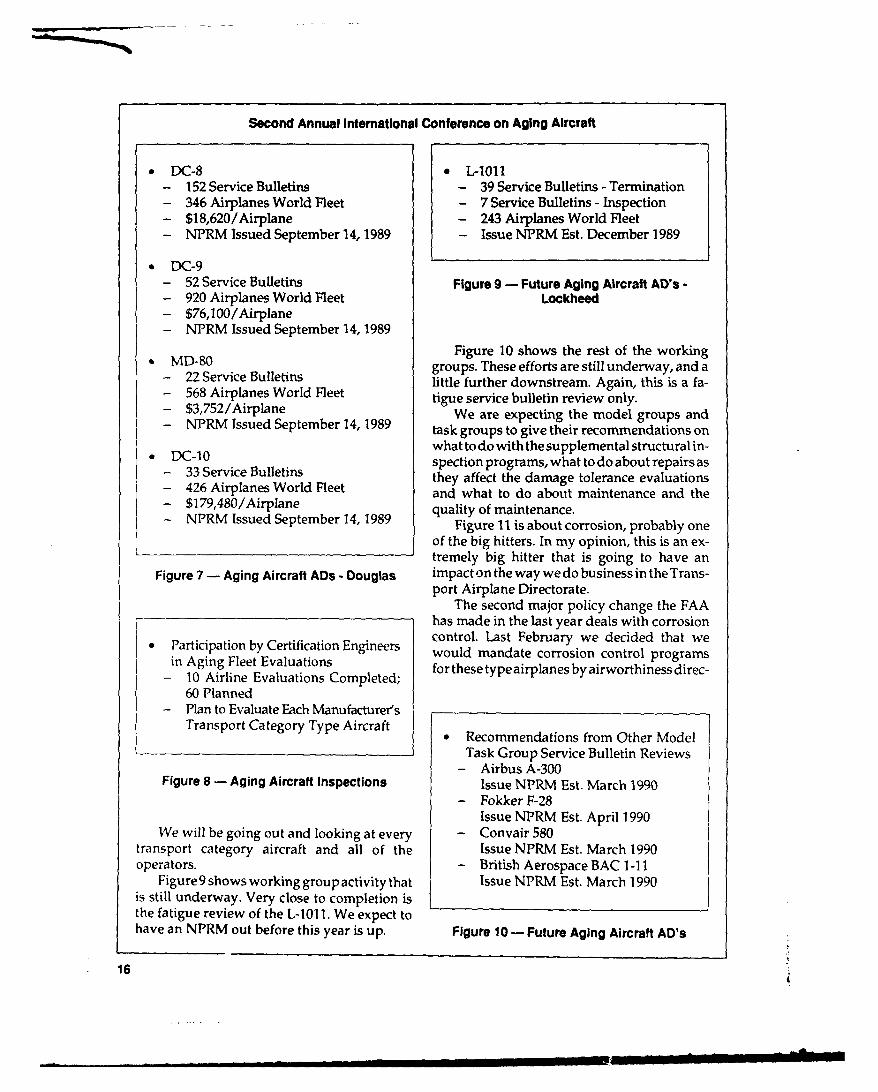
DC-8 L-1011- 152 Service Bulletins - 39 Service Bulletins - Termination- 346 Airplanes World Fleet - 7 Service Bulletins - Inspection- $18,620/Airplane - 243 Airplanes World Fleet- NPRM Issued September 14, 1989 - Issue NPRM Est. December 1989
" DC-9- 52 Service Bulletins Figure 9 - Future Aging Aircraft AD's -- 920 Airplanes World Fleet Lockheed- $76,100/Airplane- NPRM Issued September 14, 1989
MD-80 Figure 10 shows the rest of the working2 MDSO c Bgroups. These efforts are still underway, and a- 22 Service Bulletins little further downstream. Again, this is a fa-- 568 Airplanes World Fleet tigue service bulletin review only.- $3,752/Airplane We are expecting the model groups and- NVRM Issued September 14, 1989 task groups to give their recommendations on
DC- 10 what to do with the supplemental structural in-C- 3Srispection programs, what to do about repairs as
- 33 Service Bulletins they affect the damage tolerance evaluations- 426 Airplanes World Fleet and what to do about maintenance and the- $179,480/Airplane quality of maintenance.- NPRM Issued September 14, 1989 Figure 11 is about corrosion, probably one
of the big hitters. In my opinion, this is an ex-tremely big hitter that is going to have an
Figure 7 - Aging Aircraft ADs - Douglas impact on the way wedo businessin the Trans-port Airplane Directorate.
The second major policy change the FAAhas made in the last year deals with corrosion
Participation by Certification Engineers control. Last February we decided that wePrticion b lertiation Ewould mandate corrosion control programs
- 10 Airline Evaluations Completed; for these type airplanes by airworthiness direc-
60 Planned- Plan to Evaluate Each Manufacturer's
Transport Category Type Aircraft .Recommendations from Other ModelTask Group Service Bulletin Reviews
- Airbus A-300Figure 8 - Aging Aircraft Inspections Issue NPRM Est. March 1990
- Fokker F-28
Issue NPRM Est. April 1990We will be going out and looking at every - Convair 580
transport category aircraft and all of the Issue NPRM Est. March 1990operators. - British Aerospace BAC 1-11
Figure 9 shows working group activity that Issue NPRM Est. March 1990is still underway. Very close to completion isthe fatigue review of the L-101 1. We expect tohave an NPRM out before this year is up. Figure 10 - Future Aging Aircraft AD's
16
_ El I I I i . . . - L -

Leroy A. Keith
Recommendation from Model Task 0 Require SID Programs for All AirplanesGroup Review of Corrosion Program Certified to CAR 4b or FAR Part 25 -
- Boeing 707/727/737/747 to FAA HQ March 1990Issue NPRM Est. November 1989 0 Amend FAR Part 25.571 to Require 2
- Douglas DC-8/9/10 Life Times Fatigue Test - to FAA HQIssue NPRM Est. February 1990 January 1990
- Lockheed L-1011 0 Issue Revision to AC 25.571 - to FAAIssue NPRM Est. March 1990 HQ January 1990
- Airbus A-300 0 Propose SFAR to Require Fatigue Test-Issue NPRM Est. March 1990 ing of Existing Airplanes to 2 Life-
- Fokker F-28 times. (Retroactive Rule) - To FAAIssue NPRM Est. April 1990 HQ January 1990
- Convair 580 0 Issue New AC 25.1529 - To F.R. Pub-Issue NPRM Est. March 1990 lication November 1989, for Comments
- British Aerospace BAC 1-11 0 Issue New AC on Aging Aircraft Pol-Issue NPRM Est. March 1990 icy - FAA Coordination November
1989
Figure 11 - Future Aging Aircraft ADs
Figure 12- Future Regulatory Action
tive. We just received the Boeing working group'srecommendations and we plan on having an relates to damage tolerance and repairs. We'veAD NPRMsoon.Therewillbemorecomingon been working on that one for a number ofcorrosion control but we fundamentally will months.plan on a mandatory corrosion control pro- The new aging aircraft policy that we havegram for all transport aircraft operated in U.S. in coordination right now and plan to issueair carrier service, next month, talks about some of the policy
From the regulatory standpoint, we have changes made in the last year.some significant activities underway as shown In summary I would like to say I feel that itin Figure 12. A lot are internal in the Transport was a magnificent effort on the part of theDirectorate. These are internal evaluations right international aviation community to go to worknow and they're subject to change. the way we all did since June 1988, to make sure
A couple of items I'd like to call your atten- that there aren't going to be any more "Alohas."tion to on that figure are the second and fourth There have been a lot of accomplishments.bullet concerning two lifetimes of fatigue test- I have been very gratified with the work that Iing. The 25.571 rule would affect future design. have seen and the cooperative efforts that haveWe're also planning on proposing a special been made.Federal Aviation Regulation that would re- Still, there is certainly a lot more work thatquire fatigue testing of the existing fleet to two needs to be done with the aging aircraft. Therelifetimes. It would be a retroactive rule. are going to be some fundamental shifts, as I've
I want to stress that we do not believe that said, in the way we do business, especially as tofatigue testing is the ultimate solution to the the way it relates to corrosion and especiallyaging aircraft program. But it can help you concerning the Transport Directorate. I justbetter design SID documents or inspection made a quick calculation this morning. Weprograms or you can find unexpected, possibly have expended about 20 percent of the totalmultiple site damage that you hadn't predicted Transport Directorate resources on aging air-or found. AC 25.1529, which will be published craft today. Resources that we weren't spend-next month, is continued airworthiness as it ing last year. When we get into the corrosion
17

.... ...
Second Annual International Conference on Aging Aircraft
control business, it's going to take even more. believe, and in fact we are preparing a systemsThere's going to be a large involvement of working group dealing with transport aircraft,Transport Directorate engineers in monitoring and it's being structured almost exactly thethe health of the fleet. way we handled the aging aircraft program.
One of the measures of success of the way I'm comfortable in saying the fleet is cer-we have approached the aging aircraft prob- tainly safe today. If it weren't, the Transportlem is reflected in what happened following Directorate would be taking steps to do more.the tragic accident of United Flight 242 in Sioux We did ask that basic question early on: "ShouldCity last July. You recall the Administrator we park the airplanes at a given time?" Rightannounced then the formation of another group now we have no plans to have a mandatoryto be under the R&D advisory committee retirement age, but it's safe to say that the costsumbrella that Joseph Del Balzo is in charge of. are certainly going to be going up in maintain-The group is the Transport Aircraft Safety Sub- ing these older airplanes.group. That group is being chaired by ATA, I
18

Commuter Aircraft Certification
BARRY D. CLEMENTS
Manager, Small Airplane Directorate, FAA Central Region
Good morning. It is very much my pleas- The comr..LLtr class includes some trans-ure to speak to you this morning. Assisting me port category airplanes used in regional oris Bob Sexton, the Manager of our Aging commuter service. These are smaller airplanesCommuter Aircraft Program Plan. that the Transport Directorate has agreed we
Leroy Keith reviewed the transport airc:a ft should handle.program plan, some of their actions, some of I'm sure our friends at Aloha are tired oftheir accomplishments, and you've heard about seeing that mishap used as a catalyst, but in factthe need for action this morning from Con- it did act as a catalyst to focus renewed atten-gressman Oberstar, and from Tony Broderick. tion on the issue of aging aircraft in the com-You certainly are aware of it yourselves. We're muter fleet. We had to move very quickly fromtalking about actions not only by the FAA, but the talking about someday having a problem toby the industry and the other airworthiness developing an action plan to avoid a problem.support agencies. A significant and growing (See Figure 1)percentageofourregionalorcommuterfleet, is The second bullet is probably one of themade by non-U.S. manufacturers and we are most important ones we're able to share withgoing to have to enlist the support of the other- you. There has been no dramatic failure of athan-FAA airworthiness authorities to help us commuter airplane due to aging and we intendgeta handleon thecommuteraircraft program. to ensure that those airplanes used in regional
I'll review what's planned and what has passenger service do not have a structural fail-been accomplished to date on the commuter ure due to age-related issues.class of airplanes. Frankly, we're not as far into We have a pretty good workload. As showntheprogramas theTransport Directorate. They in Figure 2, the 1988 Regional Airline Associa-had a bit of a head start on us. tion figures show an air carrier passenger fleet
We do havesome important parallel efforts of 1,800 airplanes, 59 different types, 17 differ-to our engineering program and those are in ent manufacturers, and about 165 different op-maintenance and the research and develop- erators. It's a tremendous workload to try andment community. get a handle on. That includes, as I said, some
19

Second Annual International Conference on Aging Aircraft
Our approach has been to initiate this pro-" The April 28, 1988 Aloha structural gram within the available resources, and we
failure acted as a catalyst to focus have finite resources. We decided to addressrenewed attention on the issue of aging those aircraft with under 60 passenger seats,aircraft. not covered by the ATA/AIA task force initia-
" There has been no dramatic failure of tives, in scheduled or air carrier commutera commuter airplane due to aging. service, and initially those with a passenger
" The Aging Commuter Airplane Pro- capacity of 10 or more seats.gram is intended to assure that an This results in 1,180 airplanes or 66 percentairplane used in regional passenger of those used in the scheduled regional airservice does not have a structural fail- carrier fleet. Those are the airplanes most oftenure due to the issues related to aging. used in their operation, so we are confident we
are addressing a much greater percentage ofthe total passenger seat capacity of the com-
Figure I - Background muter fleet. We will be working with 92 opera-tors and 16 manufacturers.
The program content will initially be a serv-The 1988 Regional Aircraft Passenger fleet ice bulletin review for those service bulletins
that relate to aging issues, and appropriatea 1800 airplanes closing action; and a review of airworthiness0 59 different types directives we have on the books to see whicha 17 different manufacturers ones should be changed, perhaps from recur-* 165 different operators rent inspections to closing actions.
We had to have input on the very impor-Includes tant issue of maintenance considerations. We
are looking for recommendations from the* Transport Category Airplanes technical oversight group. And we are looking* Small Airplanes to SID and structural SID development and" Latest Designs approval. At some point in the process we have" Designs over 40 years old to get into major repair reviews: was enough
consideration given to fatigue and corrosion inthose repairs?
We're developing supporting regulatoryFigure 2 - Regional Fleet and policy actions and we have other actions,
for example those being taken by the R&Dtransport category airplanes, certainly what community.we call small airplanes. It includes some of the The airworthiness directive and servicelatest designs and technology and some de- bulletin review will be similar to the AIA/signs over 40 years old. ATA/Transport Directorate initiative. In this
The commuter program is going to be very, case, considering the limitations on manpowervery similar to the transport program, but with in the commuter regional air carrier industry,some differences due to the size, the design of it's going to be an FAA action with industrythe airplanes, the complexity of them, and the support instead of the reverse.smaller resources in terms of manpower of the We will review ADs for possible terminat-commuter or regional air carrier industry. And ing action and we will be reviewing age-relatedas with their program, ours has to be based on service bulletins for possible closing or manda-a mutual commitment from industry and the tory action.government, from the FAA, from the RAA and The technical oversight group's recommen-the operators, from GAMA and the manufac- dations are going to be very important to us inturers themselves, establishing and identifying whether we have
20

Barry D. Clements
a SID need; certainly in prioritizing the aging their efforts and ours. GAMA hosted a corro-airplane reviews; the adequacy of continued sion conference in March in St. Louis. GAMAairworthiness information that's available to and RAA jointly hosted the Commuter Inter-the industry now; and the adequacy itself of national Aging Conference in Kansas City insome of our service bulletin and AD actions April. We received the recommendations comingthat are presently out there. from that conference in June. We are continu-
The SID program is going to be very similar ing to develop our program plan.to the transport effort. There is a GAMA format We've had a number of meetings with theunder development. We are very anxious to technical oversight group and we're anxioussee the proposal that is forthcoming very shortly. for them to complete their site visits and makeWe envision the manufacturers developing the their reports available to us.SIDs, with FAA approval, in part if not all, and We had a meeting in August with Canada'sappropriate AD action to mandate those. Department of Transport, and Boeing de Hav-
We're still trying to get a handle on major illand, regarding an initiative needed on the derepair reviews and on how best to conduct Havilland fleet. It was a very productive meet-them. We see a very great problem in terms of ing. We are working very closely with themrecord access, record availability. But wedo see and I thank them publicly.a need for an industry review of existing airframe GAMA is developing the format for therepairs. Were the considerations for fatigue SID development program, a joint industry/adequate? Was corrosion control adequately FAA approach. We'll be proposing that shortly.addressed? Were repetitive inspections suffi- We are looking to industry to develop somecient to ensurecontinued airworthiness? Those damage tolerance, and to develop and conductare issues that have to be reviewed, some damage tolerance studies to support what
We have several initiatives underway in is going to be proposed in the SIDs.the areas of supporting regulatory and policy The SID development, of course, will be aactions. One, we are considering proposing long-term process running through early toeither rules to mandate SIDs or place hard mid-1991. The SID approval and FAA/ADlifetimes on those aircraft using commuter issuance to mandate those SIDs will follow inservice. Can they be maintained, or do they lock step.become paperweights? We intend to develop an NPRM and put
We are developing, and we will be propos- that out for an extensive comment period, toing, rulemaking addressing aircraft issues. For allow comments from the international indus-example, corrosion control in the initial certifi- try. We expect to have a final rule by early 1991.cation process. Figure 3 shows completed actions to date. I
We have, in a joint effort with Flight Stan- mentioned the GAMA-sponsored corrosiondards, a reviewof our service difficulty system. conference in St. Louis, a RAA and GAMA co-Are we getting the adequate information back sponsored conference in Kansas City, the de-to address both new certification and our aging velopment of 23 recommendations, all of whichaircraft program? we and other parts of the FAA are looking at.
There is a joint industry/FAA evaluation Many of which we acted on or are acting on,of possible licensing of NDI inspectors and a and some that we still have open IOUs on,level of effort in human factors consideration in unfortunately.NDI and NDE testing. Industry and FAA have a firm commit-
Charts 1 and 2show some of theactions we ment to jointly address the issues. We havehave taken. Again, we are exploring, more or developed a program plan for commuters similarless, the total commuter program plan. We had to that of the transport plan. It does not addressan initial GAMA/FAA/RAA steering com- the entire Part 23 fleet, if you will, but our initialmittee meeting in December 1988. We got to- actions, considering our resources, will notgether again in February 1989, to prioritize permit that.
21

Second Annual international Conference on Aging Aircraft
Im I m 1M1 190m19ACTION ITEMS DOC Mar Jute Sep De Me, JueM ep Dec Ur JueDeC
GAMA *RAA -FAASTEERING COMMITTEEMTG. (DECEMBER)
GAMA-'RAA -FAAUPRIORITIZATION(FEBRUARY)
GAMA CORROSIONUCONFERENCE(MARCH)
GAMA - RMA INTERNA-UTtONAL CONFERENCEAGING COMMUTER
AIRPLANES (APRIL)
GAMA -RMPRESENTA-UTION OF RECOMMENDA-TIONS (JUNE)
FAA DEVELOPMENT OFPROGRAM PLAN
TOGAA PRIORITIZATIONFumding approval M
*Team Idenification*Site Visits*Re~port
FAA -DOT CANArA MTG.(AUGUST)
TOGAA CDORDINATION
Chart 1 -Small Airplane Directorate, Aging Commuter Fleet Program
*GAMA Sponsored Corrosion Con-ference
*RAA/GAMA Co-sponsored Interna-tional Conference on Aging CommuterAirplanes- 23 recommended actions -
*Industry-FAA commitment to jointlyaddress issues
*FAA Developed Program Plan forcommuters similar to transportprogram
*Held first Mfgr/FAA/other Air-worthiness Authority meeting (Can-ada, DOT/FAA/BDHC)
*Other Actions by Flight Standards
Figure 3 - Completed Actions
22
Barry D. Clements
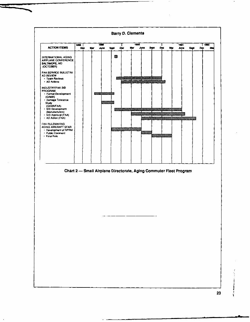
im I 'I lOU o l ju jISACTION ITEMS Dec MmW Jun 8 De Her M Jn ,ept Ae0 Hr June S Dec
INTERNATIONAL AGING 0AIRPLANE CONFERENCEBALTIMORE. MD(OCTOBER)
FAA SERVICE BULLETIN/AD REVIEW
* Team Reviews U /
* AD Actions
INDUSTRY/FAA SIDPROGRAM
* Format Development(GAMA)
* Damage ToleranceStudy(GAMAtFM)
* SID Development ,(Manufacturers)
* SID Approval (FAA)*AD Action (FAA)
FAA RULEMAKINGAGING AIRCRAFT SFAR
D Development of NPRM* Public Comment*Final Rule
Chart 2- Small Airplane Directorate, Aging Commuter Fleet Program
23

Maintenance
RAYMOND E. RAMAKIS
Assistant Director for Special Programs
Flight Standards Service, FAA Headquarters
Good morning, ladies and gentlemen. It is have accomplished already and share our plansindeed my pleasure to be here. This morning with you for the future.I'd like to share with you the Flight Standards We're going to evaluate the effectiveness ofaging fleet program, which complements Le- the airline maintenance programs and we'reroy Keith's program in the Transport Certifica- going to identify discrepancies in the programstion Directorate, and Barry Clements' in the and make changes. This will come about throughSmall Airplane Directorate. actual changes on site as they're found through
You've heard a lot about maintenance this advisory information, advisory circulars, FAAmorning. You heard about maintenance from policy changes forour inspector workforce andCongressman Oberstar, Mr. Broderick, Tom through regulatory changes for the entire in-McSweeny and the rest. Now you're going to dustry.hear a little bit more about it and some of the Our objectives are to look at the structuraldetails. It's one of flight standards' highest pri- inspection program relative to the aircraft andorities. In fact it is the highest priority program, the maintenance programs. We want to look atand a program designed to evaluate the effec- corrosion control and prevention, nondestructivetiveness of airline maintenance programs as inspection, major structural repairs, and, per-they affect the U.S. air carrier aging fleet. haps most important of all, human factors.
This program is fully underway and I'd So let's take each objective and look at whatlike to describe it to you. We believe it will go a we're going to do. (See Figure 1) In the struc-long way to eliminate the examples of aircraft tural inspection program, we start with a main-you saw earlier today. tenance planning document. That's a document
I want to give you some feedback on some developed by the airframe manufacturer inof the things we found in the 11 inspections we conjunction with the FAA. It's part of the
24

Raymond E. Ramakis
Nondestructive inspection (NDI), a criticalfactor in the review of problems on aging air-
( Maintenance Planning Document craft is detailed in Figure 3. We look at the(MPD) versus Operator's Program training given to the mechanics at the airlinesMPD Structural Sampling versus and what type of NDI equipment they use.Operators Program Does the operator contract his work out or does
* Is Operator Still Sampling he have his own people do it?" Review SSID Program We look at the certification of individuals.* On Site Inspection of Aircraft There are some industry certifications, (not
FAA's), and we actually observe nondestructiveinspection being performed on the aircraft.
Figure 1 - Objective Major structural repairs and data are coy-Structural Inspection Program ered in Figure 4. We look at the major repair
records of the airline and we examine them. WeMaintenance Review Board (MRB) process. find out if the airline classified the repairsWe take that document and match it up against properly, either major or minor, and we use athe operator's program. structural engineer to evaluate the repairs on
We also take the maintenance planning the aircraft.document and structural sampling program Human factors is shown in Figures 5. It'sversus what the operator is doing right now. one thing to talk about airline maintenance, it'sWe ask if the operator is still sampling. We another to work on an airplane at midnight, inreview his supplemental structural inspection a cold hangar, under poor lighting conditions,document program and we do on-site inspec- after you've had an argument with your wife.tion of the entire aircraft. We don't do it just on So we look at the human factors aspect ofthe day shift, we do it on the afternoon shift and the mechanic. We look at whether or not he haswe do it on the midnight shift. Our inspectors had a physical, including an eye test.are issued coveralls and everything else they We look at his work space and designneed to inspect an airplane. layout. We look at the types of stands, and
Corrosion control and prevention is shownin Figure 2. We look at the maintenance plan-ning document versus the operator's program.We look at how well he complied with corro-sion control service bulletins. Is the manufac- 0 Trainingturer's recommended corrosion control manual * Type of Equipment Being Usedbeing complied with? And we do on-site in- 0Does Operator Contract for Servicesspection of selected aircraft zones for corrosion. 0 Certification of Individuals* Observe NDI Being Performed
* MPD versus Operator's Program Figure 3 - Objective* Corrosion Service Bulletin Com- Nondestructive Inspection
pliance* Is the Manufacturer's Corrosion
Manual Being Complied with * Retrieval of Repair Records• Inspection of Aircraft Zones for * Classification of Repairs Major/Minor
Corrosion • Evaluate Repairs on Aircraft
Figure 2 - Objective Figure 4 - ObjectiveCorrosion Control and Prevention Major Structural Repalrsl/ata
2
25

Second Annual International Conference on Aging Aircraft
* Visual Acuity/Color Vision 1. Team Leader
" Workspace Design/Layout 2. Operator's Principal Maintenance
* Types of Stands/Platforms Inspector- Aircraft Overhaul Docks 3. Experienced Airworthiness Inspec-
- Construction Scaffolding tors
- Cherry-pickers 4. Structural Engineer
* Lighting 5. Human Factors Analyst from the
- Lighting Measurements Office of Aviation Medicine
- Primary Work Area Lighting- Supplementary Lighting
* Noise Figure 6- Team Composition- Noise Measurements- Ear Protection
* Eye Protection ommended maintenance and corrosion controlprograms. It's not enough to know what is onpaper. We want to know exactly what is being
Figure 5 - Objective done for the aircraft.Human Factors To do this we use a team. We start with the
team leader - the operator's principal mainte-nance inspector. That's the person who has
platforms, overhaul docks, and construction day-to-day contact with the air carrier. Theyscaffolding that he has to use to inspect an are experienced airworthiness inspectors, andairplane. we use about four of those inspectors. Even
I said before that we completed 11 inspec- though experienced, they go through a heavytions. We're going to do up to nearly 90 formal OJT program before we allow them toinspections, and we're going to do a compan- inspect the airplanes. We get a structural engi-ion, complementary, same type iteration with neer from the certification directorate; we planthe commuter category aircraft identified as to get structural engineers from the Small Air-aging. plane Directorate as part of the Aging Fleet In-
What approach are we going to use? We're spection Team. They participate in all teamgoing to do on-site evaluation of the operator's activities. And we get a human factors analystmaintenance programs and aircraft. We are from the Office of Aviation Medicine. We alsousing inspection protocols from the Boeing take nondestructive inspection experts along.company, from Douglas, and we plan to use Let me talk about some of the observationsothers. We have been given those documents we made during the 11 inspections done in thefreely by the airframe manufacturers. We've area of structural inspection, corrosion control,adopted them for the use of our inspectors. NDI, major structural repairs and human fac-They have the whole airplane categorized into tors.zones and they know exactly where to go and Now, take these in context. There isn't anywhat to look for. one of them that will cause anything cata-
We used qualified, experienced and trained strophic to happen to an airplane. But they areteams. We are gathering this inspection data symptoms of things wrong in the system, thingsand feeding it into a computer. At the end of all that need to be corrected and have been cor-the inspections we'll have a final picture of the rected.entire maintenance programs of the U.S. aging We go in, they welcome us with open arms,fleet. (See Figure 6) they give us all the information we need, and
We are going to observe, study, and corre- the feedback from them is that we have per-late the actual against the manufacturer's rec- formed a positive benefit for them. We have a
26

Raymond E. Ramakis
team right now that's at Aloha. I didn't plan it regard to the type of compounds used or theirthis way, it just so happened that's the way the application. It's one thing to have a program.schedule went. It's another thing to break it down into work
The structural inspection program is cov- cards that the mechanic will understand. That'sered in Figure 7. We found in some cases that what is imporant. The program is importantoperators' fleet sample sizes were wrong. The but you have to oe able to implement thatprogram was based on what the fleet size was program to make it effective.years ago. We found operators not removing Nondestructive inspection is anotheritems from the sampling program when de- concern. There are nogovernment standards forfects were found. They should have been. When industry to follow. There are a lot of industrya defect is found, then it should be converted to standards. There are no qualifications required,a 100 percent inspection. Sampling no longer no visual acuity test required. Everyone has aapplies. Operators have dropped sampling items different program. There's no formal programfrom their program and they can do that if they identified with the maintenance program, anddo an analysis. In some cases they just fell the calibration of the equipment is not current.through the cracks and were dropped out of What we plan to do with this one is keep ob-the program. Items removed from the sam- serving, making corrections, giving counsel,pling program, which should be put on a 100 getting things straight. We have a regulatorypercent inspection, were found to be in the review underway of FAR Part 65, (airmen othergeneral visual zonal program rather than de- than crew members), where we plan to issue antailed inspection program. NPRM that will propose a mechanic's rating
Some operators have no corrosion control for a nondestructive inspection. As you nowprogram at all. There is no real regulatory have airframe and power plant ratings, we'rerequirement to have one. You've heard Tony going to propose one for nondestructive in-Broderick say he's going to mandate corrosion spection. Nondestructive testing is very com-control by regulation, which is airworthiness plicated and if you don't do it right, you mightdirective. not catch multisite damage in the lap joints and
In cases where there is a specific program, you could have a problem.some of the work cards are too general with So we think it's significant enough to create
standards. Industry has a lot of standards, butthey are not mandatory.
Major structural repairs are shown in Fig-* Operator's Fleet Sample Size Wrong. ure 8. Sometimes we find that there are no
Program Based on Smaller Amount major repair records, and that comes fromof Aircraft than in Current Inven- confusion in the regulations. There are limitedtory. records, lost records, and improper classification.
* Operators not Removing Items from Human factors, (Figure 9), is a major con-Sampling Program when Defects Are cern. Noise levels are high, lighting levels areFound. Should Convert to 100%Inspection on All Aircraft.
* Operators Have Dropped Sampling 0 No Major Repair RecordsItems from their Program. 0 Limted Reors
• Items Removed from the Sampling 0 Limited RecordsProgram and Put on 100% Inspec- 0 Lost Recordstion Were Found to be in the General * Improper Classification of RepairsVisual Zonal Program Rather than a 0 No Reinspection Intervals for Re-Detailed Inspection Program. pairs
Figure 7- Structural Inspection Program Figure 8 - Major Structual Repairs
27

Second Annual International Conference on Aging Aircraft
Structurally the program is handled out of
* Noise Levels High Headquarters. AFS-1 means the Director of
* Lighting Levels Low/Poor Flight Standards, and AFS-3 is one of his staff
* Supplemental Lighting Inadequate people. We have two Project Managers out in
* Work Stands/Platforms Inadequate Seattle that handle this program. Eventually
* Ground Support Equipment in we plan to get up to six teams. We have about
General Poor/Lacking in Repair four people out there right now.We are going to expand that number to 25.
So we're really going to push and shove this
Figure 9 - Human Factors aging fleet inspection program.While the industry task force and groups of
people are working towards solving some of
low or poor, supplemental lighting is inade- the problems through the airworthiness direc-
quate, work stands and platforms inadequate. tive process on fatigue and corrosion, this
In a few places we visited, ground support program of necessity needs to continue be-
equipment was poor, lacking in repair, although cause you can have all the programs on paper
most larger organizations have good support you want, all the airworthiness directives you
equipment for the mechanics. want, all the structural inspection programs
Our schedule is shown in Figure 10. We you want but if you don't do the work, then
plan to extend it out a little bit in order to do at that's the problem.
least 90 airplanes, and I'll tell you how we're Our inspectors are trained. The Boeing
going to accomplish that later. company trained 300 of our inspectors and en-gineers on structural inspection document pro-
l919 119l l9ll 1912
TEAM VISITS TO AIRLINES•11 13 AIG 0A A 13Aj
REPORT INTERIM FINALA A A
COMMUTER AIRCRAFT VISITS 30A A
'IST PHASE 10 OR MORE COMMUTER AIRCRAFT
Figure 10 - Principal Activities and Milestones (Program Formation Began September 1988)
28

Raymond E. Ramakis
grams which included damage tolerance and Technical Center. We have an advisory circularcorrosion. Douglas is going to do that also, and on corrosion that's in coordination right now.train up to 300 of our people. We have a formal We're reviewing the nondestructive inspectionOJT program for inspectors. We have a corro- courses at Oklahoma City and we plan to makesion course underway in conjunction with the a major effort in the SDR program.
29

Research and Development
DICK JOHNSON
Aging Aircraft Research Program Manager, FAA Technical Center
It is my pleasure to be here this morning to define current technology gaps and develop aprovide an overview and brief summary of basis in which updated practices can be estab-FAA's National Aging Aircraft Research Pro- lished.gram. The program represents a major FAA Today, I am going to briefly touch upon thecommitment to develop and introduce new basic program elements, beginning with thetechnologies into the current maintenance, program background, major issues, overalldesign and manufacturing process. This effort research objectives and approaches, and awill ensure the structural integrity, and contin- description of the plan and status of the in-ued safe operation and maintainability of in- cluded short and long-term research studies.service and future aircraft designs beyond theiroriginally intended service lives. It should benoted that the program is being directed by the BackgroundFAA Technical Center in Atlantic City, and is intotal integration with and in support of actions The dates and initiated actions shown inbeing taken by the FAA Aircraft Certification, Figure 1 represent the basis for current re-Manufacturing and Flight Standard's Mainte- search on both the aging commuter and largenance Offices. Several of the regulatory issues air carrier aircraft starting out with the Junethat have been discussed previously (by Mr. 1988 International Aging Airplane ConferenceKeith, Mr. Clements, and Mr. Ramakis) will be which was initiated, in part, on the basic fatigueaddressed further. The primary focus will be related occurrences (including the Aloha B-737placed upon a review of emerging and ad- in-flight accident in April 1988). The primaryvanced technologies that can be applied to the recommendations for research at the confer-enhancement of current structural design, main- ence were presented by industry's Air Transporttenance and inspection procedures. Taking into Association/Aerospace Industry Associationaccount the safety and economic needs of the (ATA/AIA) and later reemphasized duringaviation industry, the program will attempt to the establishment of an air carrierindustry task
30

Dick Johnson
Issues* June 1988 International Aging
Airplane Conference Figure 2 shows the six major issues that areaddressed under the plan, and again were
" August 1988 Industry Task Force highlighted as a result of industry recommen-Initiation dations involving primarily large, pressurized,
aircraft structures. As affecting both large and* October 1988 FAA Program small airplanes, I would like to add that at this
Review/Research time the program emphasis and included tasksInitiation have been placed primarily upon the larger
pressurized transport airframe, and engine static* November 1988 Aviation Safety structures, because of a significant number of
Research Act reported fatigue-related occurrences and also,in part, because of the higher average age of the
" March 1988 Industry R&D Task transport air carrier fleet (12.1 years) as com-Unit Summary pared to a younger commuter fleet (5 years or
less)." April 1988 International Aging
Commuter AircraftConference Objective/Approach
" May 1988 FAA Research As previously discussed, the program'sProgram Plan primary objective will be the introduction ofPublication those technologies into the maintenance de-
sign and manufacturing process that will en-sure the structural integrity of high-time, highly
Figure 1 - Background cycled airframe and engine structures. Specifi-cally, we are interested in developing existing
force and an FAA program review in the fall of and new technologies that will provide us with1988. These recommendation were included the ability to predict, detect, prevent or controlunder the initiation of an FAA research pro- fatigue and corrosion in civil airframe andgram (in October 1988) and further reflected engine static structures. The approach consistsunder the subsequent "Aviation Safety Re- of short- (2 years), intermediate, and long-termsearch Act," which stated that the FAA under- (3-5 years and beyond) research study tasks.take and direct research into the development The major emphasis at this time is the comple-of technology to predict the effects of wear and tion of those near-term tasks that will providefatigue and to improve current maintenance a benefit or improvement to current in-servicepractices including nondestructive inspection airplanes, such as improved crack growth controlprocedures. In early 1989, a research program disbond inspection procedures, or improvedplan was drafted to accommodate further rec- corrosion inspection and control techniques.ommendations on large air carrier aircraft (pre-sented on behalf of the ATA/AIA research taskunit group,) and on smaller commuter aircraft 0 Fatigue/Fracture(presented by the Regional Airline Association 0 Flight Loadsand General Aviation Manufacturers Associa- • Corrosiontion (RAA/GAMA) at the April International * Nondestructive InspectionAging Commuter Aircraft Conference). In May 0 Repairs1989, a final FAA Aging Aircraft ResearchProgram Plan was published and the programbecame fully operational. Figure 2 - Issues
31

Second Annual International Conference on Aging Aircraft
Obviously, following our long-term tasks are new and updated advisory, training and regu-those that concern newer inspection concepts, latory material. At present, the plan providesand design or material properties that have for a multiyear short- and long-term researchgreater applicability to existing but primarily effort. We envision the plan to also represent ato future aircraft configurations. living document that can be updated periodi-
cally. It presently includes 27 identified re-Research Program Plan search tasks we anticipate completing during
the 2-5 year period. In the short-term segment,Figure 3 describes the basic elements of we will attempt to introduce existing and
FAA's Aging Aircraft Research Program Plan, emerging laboratory technology onto the manu-which initially provides for the identification of facturers and airlines for the benefit of theissues and the selection of recommended re- current and in-service fleet. In the long-term,search tasks that have a direct bearing on cur- we will concentrate on thedevelopment of newrent maintenance, and structural design and and advanced concepts that will have a majormanufacturing procedures. As shown, emerg- effect on the performance and maintenance ofing and advanced technologies will, and are new and future aircraft designs.being, transferred from ongoing basic researchactivities at NASA, the Department of Defense, Research Activitiesindustry institutions and universities. We pres-ently have agreements and contracts in place Some of the major short- and long-termwith these organizations. The results of this research tasks that are now underway are re-research effort are essentially a series of data flected in Figure 4. During the research sessionsbases that will provide for the establishment of beginning later this afternoon, many of these
IDEMMJSUES
* Fatigue/Fracture- Flight Loads
* Corrosion* Human Factors
SELECTr R&D TASKS T IRASFER TECHNOLOGY [E CT DTASKS !
InFecigourReeir o DOD/DOT legrity
3 Academia
DEVELOP DATA BAS.
o Handbooksv •~ Advisories -
o Standards0 Training
Figure 3 - Research Program Plan
32

Dick Johnson
ISSUES SHORT TERM LONG TERM(FY 89-90) (FY 91-Beyond)
Fatigue/Fracture • Develop Damage Tolerance * Review Analysis/TestHandbook Methodologies
@ Assess Proof Pressure Test * Assess MSC/DamageViability Tolerance Handbook
* Document DOD Tr. A/C • Evaluate Engine Life CycleLife Assessment Limits
* Evaluate Commuter Fleet * Review Analysis/TestStructures Methodologies
Flight Loads e Publish V-G-H Data Reports 9 Install Onboard Smarto Design Prototype Smart Recorders
Recorder * Conduct Flight Load DataCollection
Corrosion o Assess Corrosion Control * Develop Corrosion ProtectionAC 43-4 Handbook
* Review Manufacturer's • Conduct Corrosion CrackCorrosion Manuals Growth Control
* Develop Corrosion ProtectionTraining Material
Nondestructive * Survey NDI Equipment/ 9 Develop NDI SystemInspection Techniques Handbook
* Assess NDI AC 43-3/43-7 * Update NDI Training Manual* Evaluate Emerging NDI * Evaluate Advanced NDI
Systems Systems* Assess Engine NDI/
Microsensor Usage
Human Factors o Perform Task Analysis o Study Job Performance Aidso Study Equipment Design/ o Assess Job Selection/
Environment Placement Procedureo Assess Simulation Oriented o Develop Human Factors
CBI Handbook
Repair/MSIP Survey Engine Repair o Review Airframe RepairPractices Practices
* Document Engine ComponentCondition
* Establish Maintenance/Structural Design Integrity Plan
Figure 4 - Research
33

Second Annual International Conference on Aging Aircraft
tasks will be discussed in more detail. As shown Corrosionin the Figures, we are defining the short-termactivities as those that will be completed within Current research in the corrosion protec-the first two years of the program, while long- tion area consists of tasks being directed pri-
term efforts will be completed during a next 3- marily at corrosion control, in which case re-
5 year intermediate period and beyond. suits can be readily obtained for application tothe existing in-service fleet. Again, we are as-
Fatigue/Fracture sisting our flight standards people in the up-dating of Advisory Circular 43-4. Hopefully,
Under the identified fatigue/fracture area this update will identify new and more effec-which is being supported, in part, by NASA, tive coatings and inhibitors that have been pre-DOD, and DOT Transportation System Center, viously researched by the military. This leadswe have focused attention upon bringing up us to a review of current manufacturer pro-the level of awareness of our own technical posed manuals and into the development ofpersonnel with the development of a fracture new corrosion protection training material, allmechanics handbook or damage tolerance of which will be completed this fiscal year.design practices that will later, during the long- Long-term efforts include the development ofterm activity, be updated to include added a comprehensive corrosion control handbookdetails on multisite cracking and a further review for both engineers and maintenance personnel.of existing test and analysis methodologies. Also, as another long-term effort relating pri-One of the major efforts being taken presently marily to the structural fatigue area, we and theis an assessment on the viability of proof pres- CAA will be jointly involved in a study tosure testing as a means to ensure integrity of a determine the effects of corrosion on crackgiven fuselage structure. Other actions include growth.a review of DOD transport life assessmentprocedures and evaluation of smaller corn- Nondestructive Inspectionmuter aircraft structure for the establishmentof appropriate supplemental inspection proce- The approach taken to ensure the develop-dures. ment and introduction of new technologies
into the nondestructive inspection area was toFlight Loads survey what equipment and techniques are
presently being used, review their overall ef-In the flight load area, a major effort is being fectiveness, and then, simultaneously, provide
directed at the updating of an existing flight for a near-term evaluation of new emergingload data base. To this extent, we are working systems. This effort will be followed by a long-jointly with NASA-Langley in the develop- term assessment of new advanced conceptsment and implementation of an on board flight such as large scan holographic or neutron radi-load data collection program. During the 1970s, ography systems, or concepts which reduce orNASA collected a significant amount of V-G-H eliminate personnel workloads through use ofdata on current widebody airplanes. A joint robotics or automotive scanning systems. Atprogram with NASA is now under way to this time we are in process of reviewing a draftpublish this information and to further de- survey report which addresses current andvelop a new smart data recorder system for the existing NDI equipment used in airline service;purpose of obtaining additional in-flight gust assisting our Flight Standards maintenanceand maneuvering load data on current genera- organization in the assessment of current NDItion airplanes. The results of this effort should advisory material (43-3/43-7); and initiatingassistboth theairplanedesigneranduserinthe evaluation of other emerging NDI systems,establishment of safe and precise operating using the FAA Technical Center's B-727-100usage envelopes. [N-401. These systems include new acoustic
34

Dick Johnson
emissions and large area scan thermal systems job training procedures; therefore the needusing new image enhancement methods to re- exists to establish minimum guidelines.duce inspector workload. Long-term goals forFY-91 and beyond will include the develop-ment of a long overdue FAA NDI handbook Repair/MSIPand training material for FAA engineering andmaintenance personnel. In addition, we intend In view of recent industry and FAA fleetto look into new concepts of on-ramp engine surveys of older aircraft maintenance inspec-inspection including use of microsensors and tion and repair practices, there has been con-newly advanced automatic systems for airframe cern about the adequacy of some structuralinspection, repairs and their effect on the life of surround-
ing structures and supporting damage toler-ance design analysis. In many cases, repairs,
Human Factors such as structural patches and replacement offrame sections, may appear to be minor and
Short- and long-term research studies cov- satisfactorily meet local static loading require-ering the effects of human performance, on the ments. However, the same repairs, withoutoverall engineering, manufacturing and main- engineering or manufacturer review, could easilytenance process, first will involve a review and result in increased crack growth and failure ofassessment of personnel work tasks and envi- the surrounding structure. Other concernsronmental effects, followed "y the identifica- involving both airframe and engine repairtion of areas that could be improved - such as practices are variances that may exist betweenimprovements in equipment, equipment us- airlines and contractor repair facilities, and theage and training. The goal under the human effect these variances may have on fleet safety.factor study program will be the establishment At present, one of the near- and long-termof a human factors handbook that will include actions includes a review of these practices andequipment needs, job training, personnel per- otherrepairsand maintenancefactors affectingformance aids and updated job selection and engine and airframe life. One of the major tasksplacement procedures. At this time the major that we see developing from this effort is theemphasis of the program is aimed at the in- establishment of an overall maintenance andspection area. Civil Aviation Medical Institute structural design integrity plan (MSIP). ThepersonnelareactuallyparticipantsintheFlight plan will provide for the identification andStandard airline fleet evaluation program. With close integration of critical design issues andrespect to current funding involving this effort, maintenance action affecting the life of a givenour flight standards people indicate that there airplane. Specifically, it will provide the FAAis a wide variance of equipment and mainte- with the maintenance of documentation tonance manual instruction, including on-the- include minimum retention of permanent rec-
ords involving maintenance and repair.
35

ATA/AIA Airworthiness AssuranceTask Force
CLYDE R. KIZER
Vice President, Engineering & Maintenance, Air Transport Association
Several of the previous speakers have men- people who don't know that the problems aretioned the activities of the Airworthiness As- insoluble or unsolvable, they get resolved.surance Task Force, led by Robert Doll, Vice I'm going to borrow a comment made byPresident of Technical Services at United Airlines. Jim Marr of the Massachusetts Institute of
I think that the effectiveness of that group Technology. He was visiting Taiwan and metis unique in the history of the industry. It's withagentlemanwhoisascientistandanartistunique from several aspects: one, because of of that country. Jim marveled at the artistry ofthe activity that they have undertaken over this this gentleman.last year-and-a-half, but also more importantly, Jim asked the man if he thought that Jim, atit's unique because over 200 people have par- his age, could undertake this type of art activ-ticipated in this activity and have been able to ity, and the gentleman said to him, "Old menbreak down barriers that existed in the past to ask a lot of questions but don't make muchopen honest communications. progress. Young men don't ask any questions
And I think that we truly have a forum for and frequently make a lot of progress."open and honest discourse. That to me is the And that's truly been the case in many ofkey. If you don't have that honesty and that the things that we've done. We've turned re-openness, there's no way that you can under- ally difficult problems over to young engi-stand and address the issues. neers, and have been amazed at the creativity
The activities, of course, have been very that they bring to the problems. So it's been anproductive. The activity has been intensive, as intensive, creative and productive undertaking.related by Leroy Keith and some of the other Many in this audience are participants intask force members. It has also been very crea- what we have done over the last year-and- a-tive. Often, if you assign insoluble problems to half, and I sometimes feel that we're on a closed
36

Clyde R. Kizer
loop system where we gather together, we Aging Aircraft Task Force have been asked towork, we solve some problems, and then we participate in that meeting. So that again re-gather together to tell everybody what we've flects the true international recognition of thedone. And it's almost like preaching to the problem of continuing airworthiness and thechoir because everybody out there has been intensity with which people are trying to attackinvolved in one way, shape or form with this the problem and resolve it.whole activity. Numerous summaries of our activities have
One of the things that I'd like to stress is the been presented in various forums. What I wouldinternational scope of the activity. Several of like to do today is present a summary of whatthe previous speakers indicated that aging we recently gave to the ICAO Assembly. Thisaircraft is truly an international problem and it was an effort on the part of the FAA to informis being attacked on an international plane. that international body about our activities.
Considerable publicity has been accorded ICAO represents 170 different nations. Whatfor the Boeing working group and the Douglas I'd like to do today is run through that sum-working group, and those working groups of mary with you. This represents the latestcourse not only represent the manufacturer but summary update, as given to ICAO.are manned and staffed by all of the operators, This presentation is meant to convey theplus the regulatory agencies. We have over 94 historical background concerning the continu-separate and independent agencies involved ing airworthiness of the air transport fleet. Itin this activity, again involving over 200 people. includes the extraordinary activities intended
To get 94 separate agencies to agree to a to address the aircraft structural issues arisingcourse of action is not easy, and it is not easy to from the fact that many aircraft in the world'scommunicate with 94 separate agencies and commercial fleet are being operated beyondorganizations. But because of the quality of the their original economic design goals.people who have participated, we have been We shall start with a discussion of the back-able to do so, and do so effectively, ground, which has led us to our current fleet
In the past, the press, and perhaps our- status, followed by a brief summary of thatselves, have overlooked the fact that the inter- status and a discussion of the events leading tonational working groups are working as effec- the establishment of the ATA/AIA Air-tively as the Boeing and Douglas working groups worthiness Assurance Task Force, includingand in many cases are further ahead in their its objectives and progress to date.efforts. They haven't produced their results for Safety is the paramount issue relating to anpublication yet because of differences in the effective air transport system, and of primaryway we are going to have to promulgate that importance to the issue of safety is the air-information and ensure consistency between worthiness of the fleet of aircraft serving thatthe task units. system. From the time an aircraft is conceived
We can't overlook the activities of Lock- onthedrawingboarduntilitisretiredfromuseheed, Airbus, British Aerospace and Fokker in in the commercial system, its airworthiness isthis undertaking, because certainly it has been based on mutually dependent principles andas intense for the manufacturers and the opera- responsibilities.tors of those task units as it has for the Boeing Airworthiness begins when the aircraftand Douglas working groups. manufacturer incorporates damage tolerant
I received some information recently that design criteria according to regulatory require-the Aeronautical and Astronautical Associa- ments. That airworthiness is assured by thetion of France (AAF), which is equivalent to our airlines who must operate the aircraft in accor-American Institute of Aeronautics and Astro- dancewithaprogressiveprogramofpreventa-nautics (AIAA), is going to conduct a confer- tive maintenance.ence on aging aircraft in Bordeaux, France on The regulatory agency must provide aMarch 28th and 29th, 1990. The members of the system of surveillance to ensure that the design
37

Second Annual International Conference on Aging Aircraft
criteria are correct, that the manufacturer and With the advent of pressurization, the jetairlines operate in accordance with their de- engine, the swept wing, and the jumbo jet, wefined procedures and that any threat to air- have reached a point where major technologi-worthiness is detected, reported, analyzed and cal breakthroughs will be required to relegateacted upon in a timely and effective manner. an aircraft to a position of noncompetitiveness.
The airlines, manufacturers and regulatory Until and unless noise constraints or fuel costsagencies represent a triad of check and balance become prohibitive, the first and second gen-responsibilities meant to ensure the viability of eration jet aircraft can continue to be produc-the basic and crucial element of safety in air- tive in competition with their glass cockpitworthiness. The system has proven its effec- counterparts of the current generation.tiveness throughout the dynamic and successful These conditions have resulted in our cur-years of development of our world air trans- rent environment where a significant numberport system. It has been so successful, that over of aircraft in our commercial fleet are operatingthe years, aircraft have been retired from major beyond their original economic design goals.commercial use almost exclusively for economic We are facing a new era in our need to assurereasons when they could no longer compete the continuing airworthiness of our transporteffectively in the marketplace. fleet.
In many instances, those aircraft did not New challenges often mean that new phi-actually retire, but were shifted to another op- iosophies must be developed to meet thoseeration in which they could still perform a pro- challenges. We have faced similar challenges,ductive function for society. to our collective responsibilities for air-
With few exceptions, the ability to maintain worthiness in the past, and are required to doairworthiness has not entered the decision con- so again.cerning retirement for our commercial fleet. In When the first pressurized aircraft camefact, the industry has long believed that there into use, we found that we had to pool ourare no structural considerations which define resources so as to study this new technicallife limits for aircraft fleets. development and determine appropriate revi-
Aircraft are designed to meet many per- sions to design, test and maintenance proce-formance, tactical and economic goals. The dures in order to accommodate it.economic goals are generally meant to convey, In 1968, an industry panel of manufactur-to prospective buyers, planning considerations ers, airlines and the FAA was established tofor strategic and marketing issues. They do not address those issues. The success of that en-reflect the manufacturer's assessment of struc- deavor has led to a similar organizationaltural limitations. Economic design goals are approach to widespread industry issues, in-defined in terms of years of service, numbers of cluding the development of a new damageflight cycles and flight hours. tolerance criteria in 1978.
The fast-paced aircraft industry has devel- The industry was able to initiate revolu-oped at a phenomenal rate. The leading edge of tionary action in 1981 when it developed thetechnology moved us from wooden airplanes Supplemental Structural Inspection Programpowered by newly-developed internal com- (SSIP). This process allowed a proactive ap-bustion engines of sufficient performance and proach to maintenance problems through earlyweight to allow the briefest of flights, to our detection stemming from lead aircraft inspec-current inventory of metallic ships of the air tions. The industry was thus capable of plan-whose speed, range and comfort have allowed ning to accommodate expected maintenancemajor portions of the world's population to difficulties, rather than having to react to thembenefit from the advantages of air travel as they occurred.
That technology was a driving force to the The manufacturer was able to predict pro-economic obsolescence of our aircraft fleets. duction requirements. The airlines were able toBigger, faster, higher were always the precur- plan for appropriate resources, and the FAAsors to competitive success. had better guidance as to where problems were
38

Clyde R. Kizer
likely to occur so that they could initiate appro- cial fleet is almost 13 years. The figure indicatespriate regulatory requirements to ensure air- that better than 46 percent of that fleet is olderworthiness. than 15 years of age.
The process worked smoothly and effec- Figure 2 shows that eight common trans-tively until several aircraft structural failures port category aircraft have exceeded their eco-required that we reassess our process and our nomic design goals. Many of these aircraft arephilosophy. The seriousness and significance in common use throughout the world. Despiteof those failures required that the industry these age-related concerns and despite the struc-review the effectiveness of the well-established tural failures, which required that we questionprinciple of check and balance with respect to our current practices, the exceptional safetyour shared responsibilities. record compiled by the air transport system
These incidents demanded that we thor- and the continued safe and productive use ofoughly question our concepts concerning the those aircraft after they have left the majormeans to continuing airworthiness. airlines proves beyond question that airplanes
Let us review the status of the fleet (see are capable of operating safely beyond theirFigure 1) that contributed to our need for reas- economic design goals.sessment. The average age of the U.S. commer- Aircraft are like people; some show signs of
U.S. COMMERCIAL AIRLINE FLEET
Average Age: 12.7 Years
20 years or older960 aircraft
Under 5 years 26.2%707 aircraft 19.2%
5-10 years 15-20 years747 aircraft 14% 742 aircraft
10-15 years515 aircraft
TOTAL AIRCRAFT: 3,671
Figure 1
39

Second Annual International Conference on Aging Aircraft
The major concern rests with the interaction ofAirplanes from eight different models these two processes, for our understanding of(B-707, 720,727,737,747, DC-8, DC-9, fatigue principles is invalidated by the pres-BAC 1-11) have exceeded the economic ence of corrosion.design goal Airworthiness is not strictly a mechanical
process responding to known principles ofAirplanes are capable of operating 3tructures and materials. Human involvementsafely beyond their economic design is crucial to the process of continued air-goal worthiness. Because this will always be true,
we must develop, understand and apply knowl-edge of human interaction with the mainte-
Figure 2- Service History nance process. This must include conceptsregarding training and qualification as well asthe development of an effective man/machine
age earlier than others and for reasons not at- interface in the inspection process.tendant to chronology. The FAA brought focus to all of these con-
The major effects of aircraft ageare brought cerns when they sponsored the Conference onaboutby flight cycles due to the skin-stretching Aging Aircraft in June of 1988. That conferenceprocess involved in pressurization. Other ef- brought together over 400 world representa-fects result from hours of operation, years of tives to review the impact of aging on aircraftoperation and operating conditions. and engines and the need for improved inspec-
The major factor concerning continuing air- tion techniques and technologies to detect andworthiness for the operating fleet isdiligent ap- counter the aging effects.plication of an effective maintenance program. It was obvious to most of us who wereDespite recent events, structural failures ac- present at that conference that the technicalcount for a very small percentage of aircraft topics raised, airframes, engines, nondestructiveaccidents. testing and human factors, could not be re-
Figures 3, 4, 5, and 6 reflect the economic solved in the three days allotted for the confer-design goals and current status of the majorair- ence. Consequently, representatives of the Aircraft models prodcted in the United States. Transport Association and the Aerospace In-Most aircraft have a 20-year economical goal, dustry Association submitted a list of eightwhile the flight hour and cycle goals reflect the recommendations for consideration by thoseintended use of the aircraft in terms of stage attending the conference. The final point shownlength and flight frequency. in Figure 7, recommended the establishment of
The Boeing aircraft fleet status figure is an industry task force to resolve the technicaltypical of the expected growth in our aging issues raised at the conference.fleet resulting from the combined effects of The formula that had proven successful inhigh consumer demand, limited existing ca- the past was recommended once again, thispacity and extended lead time requirements time with a scope and scale that is unprece-for fleet replacement. dented in the world of aviation. Once again, the
The two major threats to the continuing air- triad of manufacturer, regulator and operatorworthiness for aircraft are fatigue and corro- were called upon to contribute their expertisesion. The mechanics for fatigue are generally and experience in response to a common threat.well-understood and our continuing mainte- Since the issues were not confined to inde-nance programs are based on these concepts pendent state borders, the resolution of those
Corrosion is not confined to age, for it can issues had to be international in scope. Thus,begin the moment two dissimilar metals are the parallel participation of an internationalbrought in contact on the assembly line. As triad was organized and enacted.aircraft age, the incidence of fatigue increases Figure 8 depicts the pyramid organiza-and corrosion can become more widespread. tional approach adopted to include a steering
40

Clyde R. Kizer
Atr . ALI ECONOMC HUMBER OF AIRPLANESAIRPLANE R"1AL ECNIC X N jjJVJRNT
MODEL SERVICE COEIGN°AA%DATE Ny W F~RoeF~4
A~N J- 75% 100%
SEPTIMER 213 20.000 FLIGHTS 170 59IM 80 (729) 60.000 HOURS 152 47
20 YEARS 192 123
720 JULY 6,00 FLIGHTS 14 7I19 7 14 40,000 HOURS 14 6
(153) 20 YEARS 14 14
727 FEBRUARY 60.000 FLIGHTS 170 2
19, 123 1649 50000 HOURS 785 358(1821) 20 YEARS 734 435
FEBRUARY 75,000 FLIGHTS 52 319" 132 (1490)3 51.000 HOURS 226 38
(____) 20 YEARS 297 9
747 K>JANUARY 20,000 FLIGHTS 64 5
1970 67 614 60,000 HOURS 222 68(648) 20 YEARS 10 0
> AIRPLANES REPORTED TO HAVE FLOWN DURING iM.
1> SPECIAL DESIGN LIFE OBJECTIVES HAVE BEEN ESTABLISHED FOR -SP AND -. R DERIVATIVES.
5> AT TINS POINT IN THE AIRPLANE LIFETIME. SOME INITIAL FATIGUE CRACKING MIGHT OCCUR.
Figure 3- Service History (March 1988)
A NO. ACIFT ACIPT DEs1oN DSIGN DESIGNMOL BILT CURRENTLY OBJECTIVE NO. ACFT OBJECTIVE NO ACEI ORJECIVC NO. ACFTBU IN fFLEET FLT-CYCLE EXCEEDING FLIT Ins EXCEEI)I(; YEAnS EXCEEDING
DC&a.n1 1 30 26,000 49 50.000 203 20 350
(DC.9IM DC O1176 924 40.000 1 04 30000 635 20 114
1I-1WI1543 496 50.000 0 50.000 n 70 0
440 42S 42.000 0 60.000 0 t0 0
Figure 4- DAC Commercial Jet Aircraft Fleet Status
41
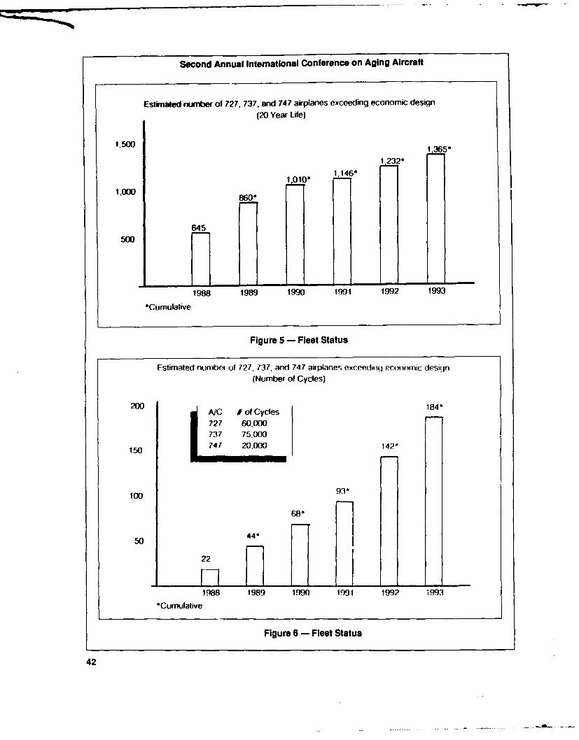
Second Annual International Conference on Aging Aircraft
Estimated number of 727, 737. and 747 airplanes exceeding economic design(20 Year Life)
1.500
1.23200 1,146*
1,000 8°*
645500
1988 1989 1990 1991 1992 1993
*Cumulative
Figure 5 - Fleet Status
Estimated number of 727, 737. and 747 airplane, exceedf iq economic desiqn(Number of Cycles)
2 A/C # of Cycles 1841
727 60.000737 75.000
150 747 20,000 142*
100 93*68"
50 44*
22
1988 1989 1990 1991 1992 1993
*Cumulative
Figure 6 - Fleet Status
42

Clyde R. Kizer
* Continue to use present system of maintenance and inspection with diligence andthoroughness. Find out why a single airplane suffered major structural failure andadjust systems as necessary.
* Initiate research to find better ways to assess structural condition and detect structuralproblems.
" Continue to pursue concept of tear-down of oldest airline aircraft to determinestructural condition and conduct fatigue tests on older airplanes.
* Pursue transfer of availablebody of knowledge of NDT and its application to airplaneinspection.
" Put research and development money into improving NDT techniques and methods.* Examine all aspects of human factors involved including training and qualification of
airline inspectors.* Ensure that the communications systems among airlines, the manufacturers and the
regulatory authorities are adequate.* Establish task forces from the airlines, manufacturing industry, FAA and NASA to
continue the work begun at this conference.
Figure 7 - Aging Aircraft Conference in Washington, D.C., June 1-3, 1988Airline/Manufacturer Recommendations
Stering Committee
I I
Un ed Bom ng/ FA Amer can/Douglas/FAA Alrbus-Conva lr-Fokker-British Aircraft Corporation
Task Groups Task Groups Task GroupsSTOY DC-3/6/7 - BAC 1-11/U.S. AIR
727 DC-8 - AIRBUS/PAN AM
737 DC-9 - FOKKER/PIEDMONT747-D- L-101 1IEASTERN-- 47DC-iO
CV-580
Figure 8 - ATA/AIA Airwothiness Assurance Task Force
43

Second Annual International Conference on Aging Aircraft
committee representing all agency and organ- organized along manufacturer product linesizational factions of the task force and three for Boeing and Douglas aircraft. The remainingworking groups which encompass all aircraft manufacturers are represented in the Interna-models employed by most major world air tional working group, comprised of Airbus,carriers. Lockheed, British Aerospace, Fokker, and
Figure 9 lists the 32 U.S. carriers and two Convair.military participants and the 42 international These working groups are composed of thecarriers who have contributed so effectively to front line engineering and technical personnelthe success of the task force. In addition to the who have the daily responsibility for the air-operators, seven airframe manufacturers and worthiness of their respective fleets. There arefive regulatory agencies are a part of the effort. over 200 individuals involved in this task force.
Finally, NASA and the Professional Avia- All activities are conducted during monthlytion Maintenance Association (PAMA), are rep- meetings, many of which require two to threeresented on the steering committee. weeks of preparation in order to adequately
The problem was large, with significant address the issues at hand. Leroy Keith indi-ramifications and the size and scope of the task cated earlier that there have been 113 suchforce reflects the sense of urgency needed to meetings sincp this task force was formed.address the concern. The goal was to bring The working group objectives are depictedtogether the most comprehensive body of tech- in Figure 10 and have been reviewed by previ-nical experience and expertise possible so as to ous speakers. They are short-term in natureaccurately define the problems and provide the and reflect the priorities of establishing im-best collective judgment to the resolution of proved safety margins for structural integrity,those problems. and developing an effective corrosion preven-
We identified the world users of the aircraft tion and control program to assure the viabilityfleets from the aircraft manufacturers' listings of the maintenance process.and invited operators of those fleets to partici- The first objective required a review of allpate on the basis of their fleet size. structural problems that have affected the fleet
Generally, 60 to 70 percent of the popula- since the specific aircraft model was introduced.tion of the world's fleet for the aircraft models This was accomplished during a review ofof concern is covered. Working groups are existing service bulletins, which are manufac-
Airlines - USA Airlines - International
United Evergreen Air France Scandinavian Dan AirAmerican Hawaiian SWISSAIR Air Canada AnsettDelta Midwest Express British Air German Cargo Service TATFederal Express Orion Air Alitalia Iceland Air LingeflugAloha Emery KLM Nationair MinervePiedmont United Parcel Service Lufthansa Trinidad Aero LloydNorthwest Braniff Britannia Saudia Oman RoyalUSAir Batch Air Canadian UTA TransfrickTrans World Dalfort Japan Airlines Va.ig World Ways CanadaEastern Emerald Air Qantas Gulf Air AustralIlan Am International Air Korean Thai Airways BWIAContinental Polaris Aircraft Alisarda Air Inter FinnairAmerican West Trans Continental Avensa Aer Lingus GarudaAlaska SunworldSouthwest MidwayFlying Tigers USNAirborne Express USAF
Figure 9- Airworthiness Assurance Task Force Working Group Participants
44

Clyde R. Kizer
generic corrosion prevention and control* Service bulletin review program.* Corrosion directed inspection program Other working group objectives include a* Review maintenance program for review of existing maintenance programs to
guidelines/recommendations determine if recommendations should be made* Review SSIP/SSID for effectiveness/ concerning limitations of such programs, a
recommendations review of the SSIP to determine if that program* Develop guidelines for structural has been effective with respect to its original
repairs in relations to long term op- intent, and a review of existing structural re-erations pairs to determine the need for additi3nal action.
The composition of the steering committeeheaded by Bob Doll (refer to Figure 8) reflects
Figure 10 - Working Group Objectives/ the parallel international scope of that body.Activities The function of the steering committee is to
define the objectives of the task force, provideturer-initiated action documents to address guidelines for the consistent accomplishmentreported fleet problems. of those objectives, ensure that time lines are
The collective experience of the working kept, and to provide coordination and resourcesgroup elements was then brought to bear on for longer range objectives.the issue to determine if mandatory action These objectives are delineated in Figure 11should be initiated for some of those service and includecoordination with the FAA humanbulletins based on their possiblesafety implica- factors efforts led by Dr. Shepherd of FAAtions and their difficulty in detection. Several Headquarters, establishment of a committee tothousand such service bulletins have been develop improved methods for technical datareviewed and two of the working groups have collection, analysis and distribution on an inter-made recommendations concerning manda- national basis, development of research andtory action. development efforts with respect to non-
The Boeing working group recommended destructive testing technologyand fatigue test-that 161 service bulletins become mandatory, ing and development of recommendations forwhile the Douglas working group recommended standardized training and qualification require-that 159 service bulletins become mandatory. ments for inspectors and mechanics. All ofThe FAA, as indicated earlier, is taking the these projects are well underway.necessary action to promulgate these recom- The Airworthiness Assurance Task Forcemendations in the form of rulemaking. Other was originally intended to complete all of theregulatory agencies will act as determined by objectives under its charge by the end of 1989their review of the proposals and the actionstaken.
All of the working groups have essentially 1completed their efforts regarding the develop- * Human factorsment of recommendations for an effective cor- * Maintenance communicationsrosion prevention and control program for their • Non-destructive testing technologyspecific aircraft models. Once compiled, this * Fatigue testingprogram will be submitted to the FAA and 0 Inspector/mechanic training andother regulatory agencies for consideration and qualificationsaction in the form of regulatory requirements. Industry commitment to fix the tech-
I might mention that since this text was pre- nical problems before political solu-pared, we have presented the Boeing working tions are forced upon usgroup program, which has been reviewed andadded to by other working groups, in a sub-committee action. This will form the basis of a Figure 11 - Long Term Objectives
45

Second Annual International Conference on Aging Aircraft
and then its activities were to be dissolved. The for the steering committee, and an annual basisunparalleled success of the individuals partici- for the working groups, so as not to lose thepating in the task force in achieving open, valuable synergism that this group has devel-honest and effective communications and ac- oped.tion plans indicates that this effort and its The task force was formed to address tech-,effects are too valuable to allow complete dis- nical issues in a responsible and responsivesolution. manner. I believe we have done that and I think
The intent at this time is to continue the the testimony and the activities to date indicateactivities of the steering committee and work- the success of the organization is unparalleleding groups, perhaps on a quarterly schedule in the history of the air transport system.
46

NASA Aging Aircraft Efforts
DANIEL R. MULVILLE
Deputy Director, Materials and Structures Division, NASA Headquarters
It's a pleasure to be here and have an op- Within the past year, NASA has developedportunity to discuss the activities that NASA is a focused program in coordination with theundertaking in support of the aging aircraft FAA to address specific issues that are relatedissue. We see the FAA as the lead agency directly to the issue of aging aircraft. We havewithin the government to undertake these signed a memorandum of agreement with theactivities, and our role is to work with the FAA FAA, which is focused in the areas identified inand to develop technology that would support Figure 1; nondestructive inspection andtheir actions. nondestructive evaluation, fracture fatigue tech-
What I will do toda; is provide a back- nology, and structural integrity predictionground in terms of our past activity and the methods.specific issues that we are focusing on at the The NASA program has been coordinatedpresent time and what we see as the opportu- with Dick Johnson and Nelson Miller at thenities for the future. FAA's Technical Center and we intend to have
NASA has historically been involved in de further discussions in terms of opportunitiesveloping materials and structures technology for us to cooperate and support their efforts.to support aircraft applications. Most of you We also had a number of discussions withare quite familiar with the work that we've industrytofindopportunitiesforustotransferdone at the NASA Langley and Lewis Research NASA technology to industry and to find waysCenters. Although we did not have an Aging for us to work together with industry so thatAircraft Program a year ago, we did have a thetechnologywedevelopmightbeusedinannumber of research and technology programs effective manner in addressing aging aircraft.that focused on materials and structures activi- As Clyde Kizer mentioned earlier, the ATAties of nondestructive inspection, fatigue and conducted an assessment of aging aircraft infracture, structural life prediction methodolo- which NASA participated. Mr. Sam Vennerigies, and a host of other activities related to from NASA's Office of Aeronautics and Spaceaircraft structures. Technology is the chairman of the materials
47

Second Annual International Conference on Aging Aircraft
* NASA research programs have his- Verify stress intensity factor solutionstorically focused on airframe materi- and fatigue crack growth methodol-als and structures technology ogy applicable to multiple-site dam-
age at riveted joints." NASA initiated a focused airframe
structural integrity program to sup- * Verify nonlinear global/local struc-port FAA as lead agency for aging "-ural analysis methodology for pre-aircraft research dicting crack growth in pressurized
stiffened shell structures.* NASA/FAA memorandum of agree-
ment on aging aircraft initiated with Develop and demonstrate NDE de-focus on: vices to characterize the development
- Nondestructive inspection/non- of damage in materials undergoingdestructive evaluation (NDI/NDE) laboratory simulated life testing.
- Fracture and fatigue technology- Structural integrity prediction Demonstrate NDE technologies to
methods economically and quantitatively evalu-ate aging aircraft.
* NASA participation in ATA agingaircraft technology assessment
Figure 2 - Airframe Structural Integrity
Figure 1 - Airframe Structural Integrity Program - ObjectivesProgram - Background
tween ourselves, the airframe industry and theand structures activities that addressed research aircraft users in order to transition this technol-and technology needs. ogy to the users.
Let me get into the discussion of the goals Figure 3 is a schematic that shows the vari-of our program, which are to develop and ous elements in our program. QNDE is Quan-verify technology in the areas of nondestructive titative Nondestructive Evaluation technology.inspection and fracture mechanics, and to The NASA program includes the elements ofdevelop structural life prediction methodol- fracture analysis, as I mentioned, analyticalogy that ensures the safety of airplane structures. modeling and nondestructive inspection that
The specific objectives in that program are focuses on a verified predicted methodology toshown in Figure 2. In the NASA program, we enable us to enhance the life of airframewill develop analytical methods that enable us structures.to predict crack initiation and growth from Before I describe the elements of those pro-multisite damage in fuselage structures as well grams in detail, I will review the organizationalas other elements of the airframe; we will de- structure within NASA so you will have anvelop analytical models that permit global and idea of who the participants are in the NASAlocal analysis of airframe structure to incorpo- Aging Aircraft program. (See Figure 4)rate the fracture and fatigue prediction meth- At NASA Headquarters, Mr. Sam Venneriodology; we will also develop NDE devices is the director of the Materials and Structuresand procedures within the laboratory and Division, which is the focal point for agingdemonstrate those on aircraft elements; and aircraft research and technology in the agency.then we will provide techniques whereby they At the Langley Research Center, which has thecould be economically applied to aging air- primary responsibility for airframe structures,craft. That requires a cooperative effort be- Dr. Jim Starnes is responsible for the structural
48
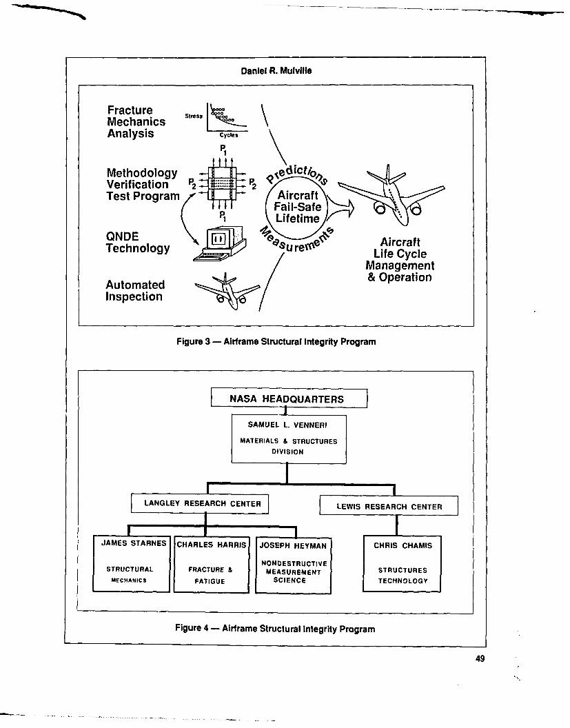
Daniel R. Mulville
Fracture StressMechanics sAnalysis cycles
P,Methodology He ict/oVerification P2 P2lt~,Test Program Aircraft
TT Fail-Safe*.6P Lifetime
ONDE AircraftTechnolo y d/re" Life Cycle
Management
Automated & Operation
Inspection
Figure 3 - Airframe Structural Integrity Program
NASA HEADQUARTERS_i
SAMUEL L. VENNERI
MATERIALS & STRUCTURESDIVISION
,_ _ - , ILANGLEY RESEARCH CENTER] LEWIS RESEARCH CENTER
JAMES STARNES CHARLES HARRIS JOSEPH HEYMAN CHRIS CHAMIS
NONDESTRUCTIVESTRUCTURAL FRACTURE I MEASUREMENT STRUCTURES
MECHANICS FATIGUE SCIENCE TECHNOLOGY
Figure 4 - Airframe Structural Integrity Program
49

Second Annual International Conference on Aging Aircraft
mechanics research and computational struc- global analysis. The formulation and verifica-tural mechanics issues. Dr. Charlie Harris, is tion of the fracture mechanics models is one ofresponsible for the fracture and fatigue meth- the developments that we see as a key to enableodology. Dr. Joe Heyman, who is developing us to make predictions for these complex struc-nondestructive measurement science methods tures which involve multisite damage.is responsible for NDE research. At the Lewis Another of the issues as I mentioned in theResearch Center, Dr. Chris Chamis is respon- scope of our activity was an assessment ofsible for developing the stochastic models for proof testing concepts. Figure 6 shows some oflife prediction of airframe structures. I'll dis- the benefits and concerns that we have con-cuss these technology areas later. cerning proof testing as it applies to large fuse-
The fatigue crack growth predictioh meth- lage structures.odology program is one of three program The potential benefits of proof testing iselements I'll be describing. The scope of this that it can be considered as a global non-program is broken down into two specific tasks. destructive inspection method. Proof testingThe first is an evaluation of proof test concepts provides a rapid way of assessing the integrityfor fuselage structures. The second task fo- of a structure, and it has been demonstratedcuses on a broader, long-term goal to develop very successfully in a number of specific appli-fatigue and fracture methodologies necessary cations, including the F-111 and B-2 wing struc-to address crack initiation and crack growth tures. But it also has been used on a number offrom multisite damage in fuselage structure. pressure vessels by the Department of De-This includes not only the analysis models but fense. For example, solid rocket motor casesalso experimental studies to verify those models. are proof pressure tested as part of the accep-
Figure 5 shows a composite of the various tance procedure.elements in the life prediction methodology. It If the proof of a metallic structure is com-illustrates the basis for the durability and damage bined with a fracture mechanics methodology,tolerance concepts that have been successfully then it can be shown that a specific level ofapplied to airframe structural design. The NASA proof test will assure a finite number of cyclesprogram focuses on crack initiation, fatigue at a specific load. A proof test approach forcrack growth models, to relate crack growth to assessing structrual integrity applies very wellthe applied loads, and some of the nonlinear to materials that have low ductility, essentiallyissues such as crack closure which causes a those materials in which linear elastic fractureretardation of crack growth due to overloads in mechanics concepts are applicable.the spectrum, as well as the significance of One of the concerns that we are addressingsmall cracks and the influence of small crack in our assessment is that there is very limitedgrowth versus large crack growth. experience on proof-testing of complex built-
Those are some of the basic elements and up fuselage structures. The issue of proof-issues that will be addressed in the fracture testing structures made from a ductile alloy, amechanics program. We will develop the stress 2024 fuselage-type metallic system, raises someintensity factor solutions which will allow the concerns about the application of the fracturepredicton of crack growth in metallic airfra- mechanics approach in ductile materials, asmes for a variety of configurations, including well as whether some damage may occur dur-multisite damage. ing the proof test.
We will conduct elastic and elastic-plastic There is another concern about the com-nonlinear analysis of some of the critical ele- plexity of corrosion and how corrosion influ-ments within the airframe, the splice joints as ences any kind of a proof-tested structure,well as the loaded rivet holes. We will analyze because crack growth in corrosive environ-short cracks emanating from rivet holes under ments is not addressed very well in a fracturespectrum loading, and then we will develop mechanics methodology.the analysis methodology to incorporate these As I mentioned, the issue of a very complexfracture mechanics concepts into large-scale structure, which would have built-up elements,
50

Daniel R. Mulville
Crack Initiation sites Fatigue crack growth data
2024-T3 2024-T3
*ls2hlSmn K 1 8 .17/ ,
dcrdN. ~c y c .... -1 p g.
11.11 2 4 tO 0 andjLong crack0. 1 M --- iacatterban
1 2 4 6 to 2o 40o too o
Stiese Intensity factor rnge. MPi-r4nt
Closure model life predictions Significance of small crack effect
2024-TI, FALSTAFF Spectru m 2024TI FALSTAFF Specirun S. a 205 MPG350
30 caf Large crack
250- sizeM ,el prediction
Msrss.- Test crackeMPa ISO size. O1 Graln crackas, Run size "
0 0 0.01 Material , Large crackdefeI j (l(no threshol)efe Test life
0 0.001 1 N ............ I10000 100000 1000000 10000000 I 0oI 10 IOo
N, cycles Fatigue life N cycles
Figure 5 - Prediction Methodology for Total Fatigue Life
penetrations, bolted and bonded configura- getting what we intend to get out of the prooftions is something that has really not been test. And that would be a specific life extensionaddressed completely in assessinE (he proof for a fixed period of time.test methodology. I'll discuss briefly the elements that we are
And, finally, if you can only assure a lim- addressing in our evaluation of the proof testited life after a proof test, then repeated proof concept. We are essentially looking at it from atests will be required and these proof loads fracture mechanics viewpoint, considering thebecome part of the overall spectrum and must various crack growth and retardation aspectsbe considered as part of the design spectrum. for 2024 aluminum alloys. We want to analyti-
So we're not saying that these are show cally establish the required proof test factorsstoppers, but we are saying that before we that could be used, using various parameterscommit ourselves to a proof test methodology such as the crack size, the crack location, con-to assure a specific life for a particular struc- figuration and the operating stress levels, andture, these are the elements that should be we have a program to experimentally conductaddressed and resolved to ensure that we are some limited testing that would load panels to
51

Second Annual International Conference on Aging Aircraft
BENEFITS
* Can provide simple, rapid, effective demonstration of structural integrity* Proven successful for military airframes
- F-111 wing box and B-52 wings- Fracture mechanics methodology- All metallic (low ductility) structures- Coordinated with stress analysis and NDE
CONCERNS
* Often discussed and seldom applied - actual experience limited* Proof testing of ductile alloys (2024 Al) raises ambiguities
- What is exact measure of fracture toughness?- Can ductile subcritical crack extension be damaging?
* Effects of proof testing corrosion-damaged material unknown* Response of complex riveted joints, cold-bonded joints, windows, doors, bulk-
heads unknown - only proven for detecting cracks in metallic structures* All structural details not equally critical - "safe life" varies with location• Repetitive proof test loading can cause significant fatigue damage
Figure 6 - Proof Testing Issues
133 percent of design limit load, (subsequently that program and intend to coordinate ourfatigue design operating load) to determine the activities with those that are being pursued byactual life of the elements. the FAA.
Figure 7 shows some of the configurations The fatigue crack growth prediction meth-we are testing and I must admit these are very odology program schedule in Figure 8 shows asimple when you consider the complexities of number of the issues that are being addresseda fuselage structure: single cracked panels, and the time interval over which this activitypanels with multiple penetrations and mechani- will be pursued. The proof test issue is the topiccally attached panels that are part of the test we are addressing at the present time, but thereprogram. These test panels will be proof loaded are a number of other activities in the fractureto design limit load and then subsequently mechanics analysis; experimental verificationloaded to design operating load which would on panels and scaled-up elements, as well asbe three-fourths of the proof load. In other the integration of the fracture mechanics meth-words, if you proof load to a level of 1.33, the odology into a large-scale structural analysissubsequent fatigue loading would be to a level program.of 1.0. I will mention some additional aspects of
This is part of the test program that we are the fracture and fatigue program later when Ipursuing at the present time to develop a data discuss the structural mechanics program andbase by which an informed decision can be the computational structural issues, becausemade concerning the benefits of proof testing. these two program elements are integratedWearehavingcontinuingdiscussionswiththe together, along with the NDE, in the totalvarious airframe industry participants, as well program.as the FAA participants, about the benefits of The scope of the second element of the
52

Daniel R. Mulville
W------4--
Test
Parameters: crack length and width multi-site damage multi-site damage.a (remote load) (pin load)
= -0.2, 0.5, 0.8 W =12" W =12"Test W 3, 12" d = 3/16 d =
Procedure: s = 1" s = 1"
(i) Determine critical crack lengths from proof tests(ii) Cycle to failure at operational load (proof load/1.33)
Figure 7 - Test Matrix to Evaluate Proof Test Concept
FY 89 FY 90 FY 91 FY 92 FY93 FY 94 AnticipatedResults
PROOF TEST
!TRESS INTENSIT)FACTOR
SHORT CRACK DATA BASE SOLUTIONS FORCRITICAL CRACK
CONFIGURATIONS
FRACTURE MECHANICS ANALYSES
EXPERIMENTAL VERIFICATION OF FLATPANEL CRACK GROWTH PREDICTION
METHODOLOGY
VERIFIED FATIGUE4,RACK GROWTH
STIFFENED SHELL CRACK GROWTH ANALYSIS METHODOLOGYFOR BUILD-UP
METHODOLOGY STRUCTURES
Figure 8- Fatigue Crack Growth Prediction Methodology Program
53
Second Annual International Conference on Aging Aircraft
Aging Aircraft Program, structural life predic- mesh is reconfigured to makepredictions abouttion and analysis verification, focuses on devel- crack growth and to conduct a fracture andopment of the analytical models to predict the fatigue analysis on a large-scale structure.overall structural response of large pressur- This summarizes the scope of the structuralized airframes. As part of this effort, we intend mechanics program in terms of the fractureto conduct some tests on prototype structural and fatigue analysis and planned testing pro-elements and subcomponents. We have also gram within NASA. Our program will includeinitiated discussions with industry whei'eby testing of small scale coupons up through biax-NASA would make predictions of structural ial testing to some panel testing and perhapsperformance of large-scale fuselage tests which some small elements in a shell structure test.would be conducted by industry to verify these NASA does not have the resources or theanalytical predictions. This activity provides facilities to conduct large-scale tests on fuse-NASA with an opportunity for us to work with lagestructures, and the optimum way for NASAindustry in a cooperative manner whereby our to work with industry is to have industry fab-technology in the fatigue and fracture and ricate the test panels and to conduct some of thecomputationalandstructuralmechanicswould panel tests and large scale fuselage elementbe verified through large-scale testing by the tests and for NASA to participate in a coopera-airframe industry. tive manner. Although we have had initial
One approach we use is the local-global discussions with some of the airframers, weanalysis where you go from analysis of an certainly would welcome opportunities to dis-entire aircraft down to panels with discontinui- cuss interactions with others within the airframeties, penetrations, elements and attachments in industry.a logical manner that enables you to transition Another aspect of the structural mechanicsthe loads from the large-scale structure down program conducted by the Lewis Researchinto the loads on the panel element. Center is focused on probabilistic structural
The specific issue that we intend to address analysis methods. In a probabilistic scheme,in our structural analysis methodology is to you don't assume that there is a specific pres-develop stiffened shell models which would be sure level or a specific geometry or perhaps arepresentative of airframe structures. These specific environment, but that there is a sto-models would include the complexities of the chastic variability associated with these para-frames, stringers, intersections and shear clips meters, and their variability is included in theand attachments, and would include linear as analysis. And so the stochastics associated withwell as nonlinear analysis, including geometri- a pressure level, the defect size and location,cal material nonlinearity. Our research will components, the material properties includingalso identify critical elements which will re- not only the metallic, but also the integrity ofquire three-dimensional structural analysis,and bonded configurations and the fastener load-develop analytical models by which we can in- ing conditions, are parameters that would becorporate the fracture mechanics concepts incorporated into the stochastic model. Thethrough adaptive methods so that as a crack approach that we propose is to use the proba-propagates through the structure, the mesh is bilistic model to predict structural responseadapted to the new geometry. and verify the model on small-scale test ele-
Figure 9 illustrates an example of one of the ments and then apply these results to large-pressurized fuselage issues, in which there is scale tests.an exaggerated view of the radial expansion, il- An example of how probabalistic structurallustrating deformations in the frame elements analysis has been used in the past is on theand perhaps some nonlinear responses in the space shuttle main engine blades. The bladesthin skin sections. operate in a very complex environment in which
Figure 10 illustrates the idea of embedding they experience thermal as well as mechanicala mesh surrounding the tip of a crack in the loading, and there are a number of variables infuselage skin, so that as a crack propagates, the terms of material properties and blade geome-
54
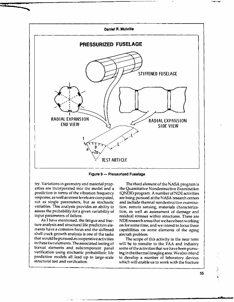
Daniel R. Mulville
PRESSURIZED FUSELAGE
STIFFENED FUSELAGE
RAILEPNIN RADIAL EXPANSIONEND VIEW ,SIDE VIEW
7TEST ARTICLE
Figure 9 - Pressurized Fuselage
try. Variations in geometry and material prop- The third element of the NASA program iserties are incorporated into the model and a the Quantitative Nondestructive Examinationprediction in terms of the vibration frequency (QNDE) program. A number of NDE activitiesresponse, as well as stress levels are computed, are being pursued at the NASA research centersnot as single parameters, but as stochastic and include thermal nondestructive examina-variables. This analysis provides an ability to tion, remote sensing, materials characteriza-assess the probability for a given variability of tion, as well as assessment of damage andinput parameters of failure, residual stresses within structures. These are
As I have mentioned, the fatigue and frac- NDE research areas that we have been workingture analysis and structural life prediction ele- on for some time, and we intend to focus thesements have a common focus and the stiffened capabilities on some elements of the agingshell crack growth analysis is one of the tasks aircraft problem.that wouldbepursued ascooperativeactivities The scope of this activity in the near termin these two elements. The associated testing of will be to transfer to the FAA and industrybiaxial elements and subcomponent panel some of the activities that we have been pursu-verification using stochastic probabilistic life ing in the thermal imaging area. We also intendprediction models all lead up to large-scale to develop a number of laboratory devicesstructural test and verification, which will enable us to work with the fracture
55
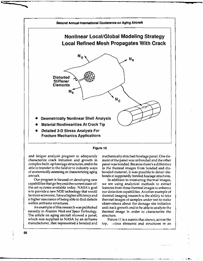
Second Annual International Conference on Aging Aircraft
Nonlinear Local/Global Modeling StrategyLocal Refined Mesh Propagates With Crack
N o N
DistortedStiffenerElements
Nx
* Geometrically Nonlinear Shell Analysis
* Material Nonlinearities At Crack Tip
* Detailed 3-D Stress Analysis ForFracture Mechanics Applications
Figure 10
and fatigue analysis program to adequately mechanically attached fuselage panel. One ele-characterize crack initiation and growth in ment of the panel was unbonded and the othercomplex built-up fuselage structures, and to be panel was bonded. Because there's a differenceable to transfer to the field or to industry ways in the thermal images from bonded and dis-of economically assessing or characterizing aging bonded material, it was possible to detect dis-aircraft. bonds in supposedly bonded fuselage structures.
Our program is focused on developing new In addition to measuring thermal images,capabilities that go beyond thecurrentstate-of- we are using analytical methods to extractthe-art systems available today. NASA's goal features from these thermal images to enhanceis to provide a new NDE technology that would our detection capabilities. Another example ofbe more economic, have a higher efficiency and thermal imaging research is the ability to takea higher assurance of being able to find defects thermal images of samples under test to makewithin airframe structures. observations about the damage site initiation
An example of this research was published and crack growth and to be able to analyze therecently in Aviation Week and Space Technology. thermal image in order to characterize theThe article on aging aircraft showed a panel, structure.which was supplied to NASA by an airframe Fiure 11 is a matrix that shows, across themanufacturer, that represented a bonded and top, -,rious elements and structures in an
56

Daniel R. Mulville
Technoiogies Landing Strut Corrosion Bonded & Structural Component & Rivet And Bolt Stress SensorsFatigue Measurement & Rivaled Lap Fatigue State Hardware Stress State & Stress
Assessment Joint Integrity Fatigue State Imaging
Magneo-AcoustlcResidual StressMeasurement
Magnetic BarkhausenSpectroscopy
Ultrasonic Plate &Surface Wave Phase
Propagation
Thermography WithExternal Heating
Thermoelasticity WithExternal Stimulus
Nonlinear AcousticTechniques 0
Cntical FastenerPreload & Certification
Ultrasonic PulsedPhase Locked Loop -
External Stimulus
Retrofit RemoteSensing Syte 101
Figure 11 O- NDE Technology Matrix
airframe, and along the left-hand side, various tems, is presented in Figure 12. We intend tonondestructive examination techniques that develop prototype quantitative NDE instru-are being explored. The chart indicates a number ments for aging aircraft, to evaluate proof ofof NDE techniques we see as potential applica- concepts in the laboratory with small scaletions for aging aircraft. We are pursuing a airframe components, develop prototype fieldnumber of these technologies at the present instruments and use baseline samples to maketime. those inspections.
An example of one of the NDE technologies NASA Langley has a Boeing 737 aircraftwe are developing is a phased array, or a large- that gives us an opportunity to conduct thesescale ultrasonic scheme, by which it is possible inspections on an operational aircraft and thento examine larger elements of the airframe and to move into field test and ultimately transferbe able to detect crack sites as well as corrosion, the technology out to the airframers and to theand that provides high resolution and oppor- manufacturers.tunities for a quantitative measurement through Finally, I'll give a synopsis on the NDE insome signal processing schemes that are cur- terms of what our near-term activities are. Werently being examined. There are a number of are working oit a coordinated program withlarge scale NDE methods such as NDE blan- the FAA and participating on the FAA NDEkets and concepts that have been applied to Committee. The three bullets in the lower partvarious airframe configurations. We are cur- of Figure 12 indicate the specific issues that werently exploring some of those for application are addressing in the area of thermal NDE.to aging aircraft. That includes thermal modeling of lap joints
How the technology that NASA develops and techniques to analytically extract featureswould eventually impact the operational sys- from the thermal image in order to measure
57

Second Annual International Conference on Aging Aircraft
S0800000000000000000000000
000
Figure-Advanced Ultrasonic Phased Array
PhiaRsluio eteton(imlr opasdara RD
.Imag AberAtinCrrayin.0u nttatve Cotrzon hr og sgnCompuroesnI g Dip y
Adacd il.Agurhed Arra Pvdane ls: ncPae ramgn
and characterize properties of specific samples. instrumenting elements to provide real-timeThe results of these studies wil permit us to feedback from NDE sensors.provide suggestions to the FAA for their ther- In summary, NASA has initiated a researchmal NDE testing, and to develop a thermal program in cooperation with the FAA to de-imaging technology and transfer capability to velop technology for enhanced airframe struc-the FAA and industry. tural integrity. I mentioned initially that we
We are working jointly with the industry in have a memorandum of agreement to addressthis area as well, and Figure 13 indicates our the three technical areas that I discussed earlieractivities for the FAA. in the presentation. We also have a memoran-
In the total scope of the NDE program, dumofagreementtoworkelementsassociatedthere are a number of activities indicated, in- with loads and loads measurements. Mr. Terrycluding lap joint inspection methods, detection Barnes of the FAA will be discussing that as-of cracks at fastener holes, inspection and ther- pect in some detail.mal modeling analytical methods, as well as We have a NASA/industry cooperativesome small scale laboratory experimental analysis and test program proposed for large-techniques. Thermal imaging and optical dis- scale verification test. As I mentioned, we'veplacements are being examined as large field had discussions with industry to identifymeasurement systems. The residual preload opportunities for us to verify fracture and fa-measurement and load distribution systems tigue analysis as well as NDE methods onare focused on mechanical attachments and large-scale structures.fasteners that can be instrumented. The technology transfer methods identi-
And at the lower end of Figure 13 are some fied for NDE, fracture and fatigue analysis, andof the longer-term concepts including smart structural life prediction are through our inter-material sensors in which we would envision actions with the ATA, through our discussions
58

Daniel R. Mulville
FY 89 FY 90 FY 91 FY 92 FY93 FY 94 RetJpaut
_________ ________ I_________ ___________________ Results
LAP JOINT & CRACK NDE, INVERSION MODELING, CORROSION PROFILE FIELD & NDEDEVICES TO& ASSESSDAMAGE
NONCONTACTINGTHERMOELASTIC STRAIN OPTICAL DISPLACEMENT/STRAIN SYSTEM LAB & FIELD
SENSOR ISENSORS FORSENOR _DISPLACEMENT/
STRAIN
FIELD STRESSINSTRUMENTA-
RESIDUAL, PRELOAD & LOAD DISTRIBUTION MONITORING TION
INTERNALNERVOUS
SMART MATERIALS SENSORS SYSTEMMONITOR OFSTRUCTURALHEALTH
Figure 13 - NDE Program
with industry and in cooperation with the FAA. dustry and to identify opportunities for us toW,. view this conference as a good opportunity work together and transfer the technology beingfor us to provide further interaction with in- developed in the NASA program.
59

Session I: Structural Fatigue
CHAIRMAN THOMAS SWIFT
FAA National Resource Specialist
The first session this afternoon is the first There has been a lot of discussion in thissession of the research and development series meeting about the aging airplane programof panel discussions and presentations. Ses- having been initiated by the Aloha accident butsion I is related to structural fatigue. the message I have is that the aging aircraft
With us today are Dr. UIf Goranson from program didn't really start with the AlohaBoeing Commercial Airplane Company, Dr. accident; it started many years ago. I thoughtPin Tong from DOT Transportation Systems I'd remind you about that fact before we continue.Center, and Ben de Jonge from the NationalAerospace Laboratory in the Netherlands.
60

Continuing Airworthinessof Aging Jet Transports
ULF G. GORANSON, PH.D.
Manager, Damage Tolerance TechnologyBoeing Commercial Airplane Company
Economic and market conditions have re- tions that will support continued safe operationsulted in the use of commercial jet airplanes of aging jet transports until their retirementbeyond their original economic design life from service.objectives. The average age of the world airlinejet transport fleet has increased from 8 to 12years since 1980. Standard Boeing practices to Introductionsupport continuing airplane structural integrityinclude inspection and overhaul recommenda- Boeing continually reviews reported serv-tions contained in maintenance manuals and ice data and other firsthand information fromservice bulletins. As airplanes exceed their eco- customer airlines in order to promote safe andnomic design life objectives, the incidence of economic operation of the worldwide fleet. Thefatigue increases and corrosion may become active service life of commercial airplanes hasmore widespread. This presentation is focused increased in recent years as a result of low fuelon recent special activities to assess the condi- costs, and incrEasing costs and delivery timestion of the aging airplane fleet and other joint for fleet replacements, (Figure 1). Air transportBoeing, airline and airworthiness authority industry consensus is that older jet transportsreviews of service bulletins, corrosion control will continue in service despite anticipatedprograms, basic maintenance and supplemental substantial increases in required maintenance.structural inspection programs and structural This paper is focused on recent initiatives torepair quality. These initiatives will provide enhance aging airplane safety in addition totimely preventive maintenance recommenda- standard Boeing practices to support continuing
61

Second Annual International Conference on Aging Aircraft
3025 Actual l 4 0 Forecast
25
20 Design Age ofobjective airplanes
Fleet at time ofag, 5 retirementage, 1
years
Average age
5 of fleet
0 1 _J
1970 75 80 85 90 95 2000
Figure 1 - World Jet Fleet Age
structural integrity by inspection and overhaul Structural Safetyrecommendations contained in maintenancemanuals and service bulletins. These actions Criteria and procedures used in commer-include fatigue testing and teardown inspections cial airplane design over the last three decadesof high-time airframes retired from service; have produced long-life damage-tolerant struc-timely development of Supplemental Struc- tures with an excellent safety record (Figure 2).tural Inspection Documents applicable to This has been achieved through diligent atten-selected older airplanes; and a 2-year surveil- tion to detail design, manufacturing, mainte-lance of 76 airplanes distributed throughout nance, and inspection procedures. Structuralthe world to gain an engineering assessment of safety has been an evolutionary accomplish-the condition of older Boeing airplanes. Con- ment, and attention to detail design the key tocerns have resulted in Boeing initiatives and this achievement. These design concepts, sup-joint manufacturer, airline and airworthiness ported by testing, have worked well due to theauthority actions. These actions are focused on system that is used to ensure that the fleet ofmandatory modification rather than continued commercial jet transports are kept flying safelyinspection defined in service bulletins for air- through their service life. This system has threeplanes exceeding design life objectives; devel- major participants: the manufacturers whoopment of improved mandatory corrosion design, build, andsupportairplanesinservice;control programs; reviews of basic maintenance the airlines who operate, inspect, and maintainprograms and supplemental structural inspec- the airplanes; and the airworthiness authori-tion programs; and development of guidelines ties who establish rules and regulations, approveto determine the adequacy of structural repairs the design and promote airline maintenancein relation to damage tolerance and long-term performance, (Figure 3). Airplane structuraloperation. safety depends on diligent performance of all
62

UIf G. Goranson
60
87%50
40 All othercauses
Hull loss*,accidents 30per million Structures 3%-.r11- Maintenance/departures 20 airplane - 13%
d Structures1 e • Systems
10 -0 Propulsion
Excludes 1960 65 70 75 80 85 90e Sabotage* Military action Year
Figure 2 - Commercial Aviation Safety Record
participants in this system and the responsibil- pacted by the cost and frequency of repair;ity for safety cannot be delegated to a single durability may, therefore, limit the productiveparticipant. life of the structure.
All Boeing jet transports are designed to bedamage tolerant, a principle that has evolvedfrom the earlier fail-safe principle. On the whole, Test Verificationservice experience with fail-safe designs hasworked very well with thousands of cases where It is impractical to conduct verification test-fatigue and other types of damage have been ing of all critical conditions and portions of thedetected and repaired. The question being airplane structure. Analysis methods and al-debated between experts in the industry, is lowables are therefore verified by test and thewhether or not the fail-safe design practices airworthiness certification substantiated byused in the 1950s and 1960s are adequate as analyses. Development and verification teststhese airplanes approach or exceed their origi- comprise small laboratory test specimens, largenal economic life objectives, (Figure 4). Boeing panels and major components representingjet transports are designed for a minimum 20 wing, empennage, and fuselage structure, andyears of economic operational service. It should full-scale airframes.be noted that there is no limit to the service life Full-scale static testing of new models isof damage-tolerant designed airplane struc- conducted to verify limit load carrying capabil-tures, provided the necessary inspections are ity and to satisfy certification requirements. Incarried out along with timely repair or replace- addition, full-scale fatigue tests are conducted.ment of damaged structure or preventive modi- The primary objective of these major cyclicfications for airplanes exceeding economic design tests is to locate areas that may exhibit earlylife objectives. Operational efficiency is im- fatigue problems. The testing is accelerated
63
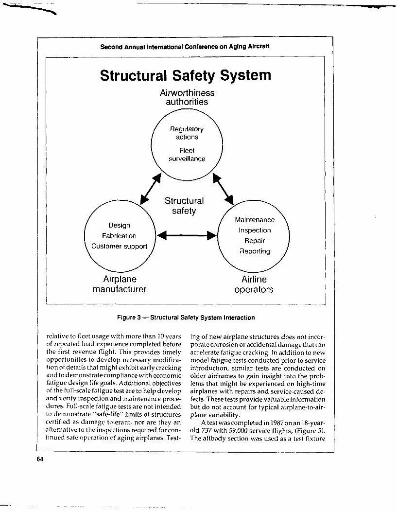
Second Annual International Conference on Aging Aircraft
Structural Safety SystemAirworthiness
authorities
Regulatoryactions
Fleetsurveillance
Structuralsafety
DesignMaintenanceDesignInspection
Fabrication PI RepairCustomer supportReotn
Airplane Airlinemanufacturer operators
Figure 3 - Structural Safety System interaction
relative to fleet usage with more than 10 years ing of new airplane structures does not incor-of repeated load experience completed before porate corrosion or accidental damage that canthe first revenue flight. This provides timely accelerate fatigue cracking. In addition to newopportunities to develop necessary modifica- model fatigue tests conducted prior to servicetion of details that might exhibit early cracking introduction, similar tests are conducted onand to demonstrate compliance with economic older airframes to gain insight into the prob-fatigue design life goals. Additional objectives lerns that might be experienced on high-timeof the full-scale fatigue test are to help develop airplanes with repairs and service-caused de-and verify inspection and maintenance proce- fects. These tests provide valuable informationdures. Full-scale fatigue tests are not intended but do not account for typical airplane-to-air-to demonstrate "safe-life" limits of structures plane variability.certified as damage tolerant, nor are they an Atestwascompletedin 1987onan 18-year-alternative to the inspections required for con- old 737 with 59,000 service flights, (Figure 5).tinued safe operation of aging airplanes. Test- The aftbody section was used as a test fixture
64

Ulf G. Goranson
Boeing Jet Fleet StatusJune 1989
Initial Active (total) 1-- Economic Number of airplanesAirplane service commercial fleet design exceeding given percentmodel date Number of Number of life [3T- of design objective
operators airplanes objective 75% 100%707 September 221 20,000 flights 180 80
1958 (728) 60,000 hours 155 5920 years 209 173
720 July 12 30,000 flights 11 3
1960 6 (153) 60,000 hours 10 01960 6_ (153) 20 years 12 12
727 February 1,643 60,000 flights 244 121964 125 (1,819) 50,000 hours 891 43120 years 893 589
737 February 1,632 75,000 flights 80 1138 51,000 hours 281 62968 3 (1,698) 20 years 310 161
747 January 604 20,000 flights r2 111 111970 59 (639) 60,000 hours 248 103
20 years 209 0
Airplanes known 1o have flown during the past 12 months.i - Excluding -SP and -SR derivatives.I, - Al this point in the airplane lifetime, some initial fatigue cracking might occur.
Figure 4 - June 1989 Fleet Status
for damage tolerance tests of the aft pressure cycles, dependingonlapjointcondition(corro-dome and fatigue testing of typical fuselage sion, disbond), (Figure 9). Following crackpressure structure. Cracking in a longitudinal linkup, insulation blankets were installed tobody lap spliceexpanded the focus of the test to simulate service conditions and prevent obvi-include close monitoring of these monocoque ous pressure loss. These cracks (and othersdetails. At 79,000 total cycles, corresponding to developing later) were allowed to grow unre-24 years of service, multiple site damage (MSD) paired. The major crack reached a longitudinalof approximately 0.09-inch length beyond the length of 32 inches with three tear straps failedfastener head was visually detected in the skin before a change in crack direction caused "skinat seven upper row countersunk fasteners along flapping" and safe decompression at 100,600stringer 4R. This equates to a 0.43-inch tip-to- total cycles equivalent to about 30 years oftip crack, (Figure 6). The cracking pattern after typical service usage, (Figure 10) (7 years with-linkup is depicted in Figure 7 in two similarly out repairs since initial crack detection).stressed adjacent tear strap bays, either side of Repairs were made to permit continueda frame. Approximately one-third of the fas- testing of the aft pressure dome to an equiva-teners in the critical row developed cracks. Test lent of 40 years of typical operator servicedata comparison with crack growth analysis usage or 130,000 total pressure cycles. Theprediction, assuming a short linkup period crack growth testing of the elliptical aft pres-from crack lengths I inch to 5 inch, is shown in sure dome structure followed 90,000 fatigueFigure 8. The damage detectio-, period prior to pressure cycles including the cycles experi-linkup ("uring which safety inspections are encedbytheairplaneduringfleetservice.Sincecarried , it) ranges from 10,000 to 40,000 flight no naturally occurring fatigue cracks were
65

Second Annual International Conference on Aging Aircraft
I
Figure 5 - Retired 737 Aft Fuselage Fatigue Test Article
Initial 737 Stringer 4 Lap Splice Cracking79,033 Cycles
FrameSTA STA STA797 787 777
Q S 3R :M:
- aximum *. - ar i h lypical
* Initial cracking at seven fastener holes on outside skina Eddy current detection
Figure 6 - Initial 737 Stringer-4 Lap Splice Cracking
66

Ulf G. Goranson
737 Stringer 4 Lap Splice Cracking100,290 Cycles
Frame CLFrame CLFrameand strap strap 10 inch and strap strap and strap
Fuselage La~pSice SDAnlyiadTest at
0 'Iailed1.0 inc
Deecio flight0 cycles,
Fiue8-7stlage- Lap Splice ISD Analysis adTs aaCmaio
at 10,673 yc67

Second Annual International Conference on Aging Aircraft
737 Lap Splice Crack Growth Data
0.75Linkup0.-70 - .-'"h--,,sol /.,-Prediction0 treshold 1987 service (disbonded)
0.65 - airplane
0.60 (fully disbonded)-- Boeing aftbdytest (mostly
Tip-to- 0.55 - bonded)tip Visual
Crack 0.50 - detection
length, 0.45 - thresho* Normalized to
L, inch 0.40 - 025-inch crack lengthLinh0.40 I . - -
035 -Initial high-frequency j.-O 25-M.
0.30 - eddy current
0.25 range of detection
0 1 I 1 1
0 10 20 30 40 50
Thousands of flights*
Figure 9 - 737 Stringer-4 Detection Opportunities Before Linkup
Figure 10 - Controlled Decompression of 737 Fuselage Test Article
68

Ulf G. Goranson
detected in the pressure dome by this time, saw rows in a splice is related to the accessibility forcuts were introduced to simulate large detect- inspection of the structural detail. Figure 13able cracks in the dome skin lap splices. Five shows the visible interior aft side of the pres-tests were completed that included four tests of sure dome. Hidden fastener row cracks arebay centered radial saw cuts simulating cracks buried between the exterior skin in the splicealong the radial lap splices and one test with and the internal radial stiffener. Before testing,two radial saw cuts centered in adjacent bays commercial insulation blankets, as used in pro-along another lap splice. A view of the dome, duction airplanes, were installed to provide apretest stress survey strain gages and saw cut realistic air seal. Pressure cycling was stoppedtesting locations can be seen in Figure 11. Most at scheduled intervals to facilitate detailedof the testing was performed in the middle bay inspections and measurement of crack length.and one in the inner bay of the dome, as these Portable eddy current inspection equipmentare the highest stressed regions and the most was used to detect and locate the crack tips, andlikely place for cracking to occur during the life crack length measurements were made visu-of the structure. A summary of the tests per- ally using a steel scale. These pressure domeformed is listed in Figure 12. Tests 4 and 5 had tests confirmed analysis procedures used toshorter initial crack lengths, but were tested determine supplemental structural inspectionunder the same conditions as tests 1 and 2 recommendations.respectively. These tests were done to deter- I he model 747 has now been in service formine crack growth rates for shorter cracks. The over 20 years and a high-time airplane retireddifference between visible and hidden fastener from service was acquired by Boeing in 1988
Pressure Dome Structure,Strain Gage and Test Locations
Preteststress survey 0.032-in
strain gages - 2024-T42clad sheet
Crack numberand location
Radial InnerRaadial
Outer lap spliceEd e and stiffener
Figure 11 - Pressure Dome Structure, Strain Gage and Test Locations
69

Second Annual International Conference on Aging Aircraft
737 Elliptical Pressure DomeTest Summary
Test Test Splice Initial Final Crack growthTe sawcut crack test cycles*
number bay row length, inch length, inch N
1 Middle Visible 9.3 19.4 11,800
2 Middle Hidden 9.4 18.1 4,800
A Inner Visible 5.3 12.6 26,1003
B Middle Visible 5.3 15.5 19,200
4 Middle Visible 4.3 5.95 29,100
5 Middle Hidden 4.3 4.6 24,300
*90,000 fatigue pressure cycles applied prior to crack growth testing
Figure 12- 737 Elliptical Pressure Dome Test Summary
Radial Stiffener and Crack Locations
Radial Pressurized Pressurized Radialcrack side side rac7
Visible row Hidden row
Figure 13 - Radial Stiffener and Crack Locations
70
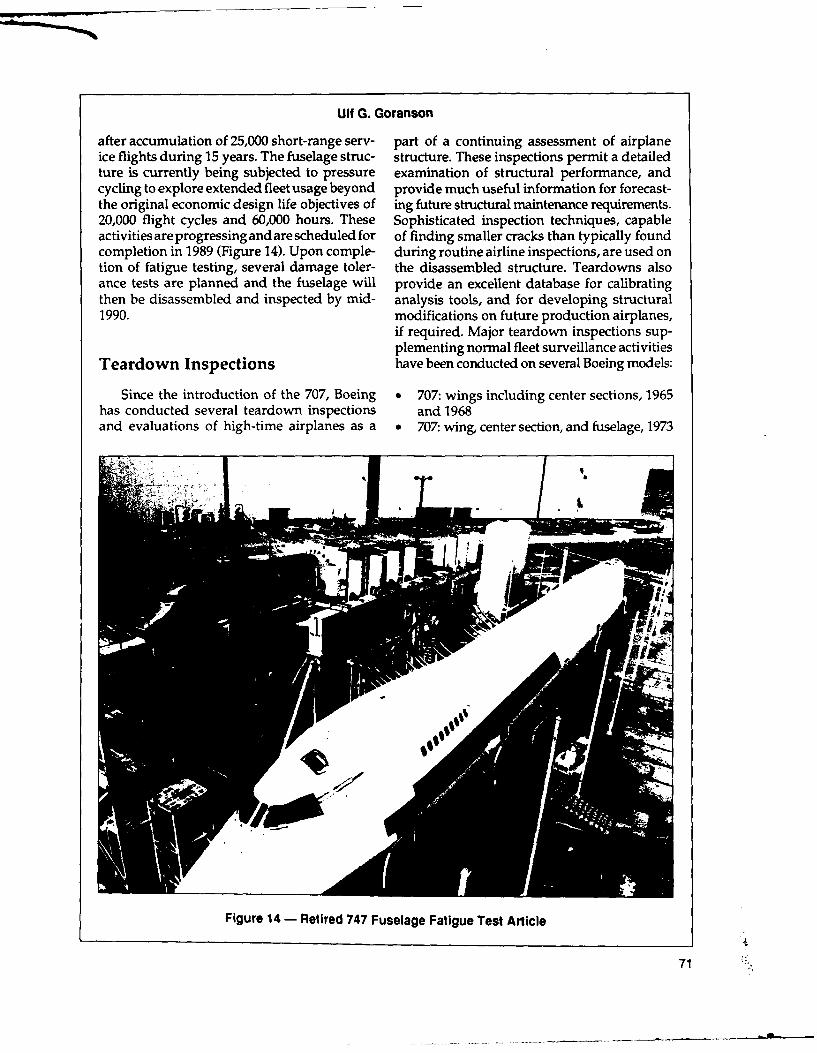
Ulf G. Goranson
after accumulation of 25,000 short-range serv- part of a continuing assessment of airplaneice flights during 15 years. The fuselage struc- structure. These inspections permit a detailedture is currently being subjected to pressure examination of structural performance, andcycling to explore extended fleet usage beyond provide much useful information for forecast-the original economic design life objectives of ing future structural maintenance requirements.20,000 flight cycles and 60,000 hours. These Sophisticated inspection techniques, capableactivities are progressing and are scheduled for of finding smaller cracks than typically foundcompletion in 1989 (Figure 14). Upon comple- during routine airline inspections, are used ontion of fatigue testing, several damage toler- the disassembled structure. Teardowns alsoance tests are planned and the fuselage will provide an excellent database for calibratingthen be disassembled and inspected by mid- analysis tools, and for developing structural1990. modifications on future production airplanes,
if required. Major teardown inspections sup-plementing normal fleet surveillance activities
Teardown Inspections have been conducted on several Boeing models:
Since the introduction of the 707, Boeing * 707: wings including center sections, 1965has conducted several teardown inspections and 1968and evaluations of high-time airplanes as a e 707: wing, center section, and fuselage, 1973
Figure 14 - Retired 747 Fuselage Fatigue Test Article
71
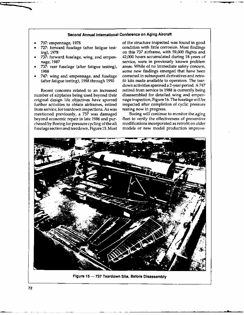
Second Annual International Conference on Aging Aircraft
* 707: empennage, 1978 of the structure inspected was found in good0 727: forward fuselage (after fatigue test- condition with little corrosion. Most findings
ing), 1978 on this 737 airframe, with 59,000 flights and* 737: forward fuselage, wing, and empen- 42,000 hours accumulated during 18 years of
nage, 1987 service, were in previously known problem* 737: rear fuselage (after fatigue testing), areas. While of no immediate safety concern,
1988 some new findings emerged that have been0 747: wing and empennage, and fuselage corrected in subsequent derivatives and retro-
(after fatigue testing), 1988 through 1990 fit kits made available to operators. The tear-down activities spanned a 2-year period. A 747
Recent concerns related to an increased retired from service in 1988 is currently beingnumber of airplanes being used beyond their disassembled for detailed wing and empen-original design life objectives have spurred nageinspection, Figure16. The fuselage will befurther activities to obtain airframes, retired inspected after completion of cyclic pressurefrom service, for teardown inspections. As was testing now in progress.mentioned previously, a 737 was damaged Boeing will continue to monitor the agingbeyond economic repair in late 1986 and pur- fleet to verify the effectiveness of preventivechased by Boeing for pressure cycling of the aft modifications incorporated as retrofit on olderfuselagesectionandteardown, Figure15. Most models or new model production improve-
Figure 15 - 737 Teardown Site, Before Disassembly
72

UIf G. Goranson
Figure 15 (Continued) -737 Teardown Site, After Disassembly
ments. Findings will be disseminated to opera- including recommendations for any necessarytors by service bulletins as required and incor- supplemental structural inspections, as an al-porated in maintenance recommendations ternative to imposing service life, operationalissued by Boeing. or inspection limitations. The resulting struc-
tural inspection program supplements existingoperator maintenance programs that generally
Supplemental Structural have been very effective in maintaining theInspection Programs inherent damage tolerance of Boeing jet trans-
port structures. Model specific documentsThe continued structural airworthiness of provide inspection options for selected struc-
aging transport airplanes has been the subject turally significant items (SSI) that will ensureof considerable discussion among experts in timely detection of fatigue damage in olderthe industry and airworthiness authorities, airplanes. This is achieved, where required, byAttention has been focused on the adequacy of use of more refined inspection techniques withininspection programs for timely damage detec- the operator's existing scheduled maintenancetion in support of fail-safe design practices program, or by supplemental inspections. Theseused during the last three decades. CAA Air- inspection requirements are applicable to thoseworthiness Notice 89 and FAA Advisory Cir- high flight cycle airplanes termed candiditescular 91-56 allow structural reassessments, since these are the most likely to experience the
73

Second Annual International Conference on Aging Aircraft
Figure 16 - 747 Test/Teardown Airplane Disassembly
earliest fatigue cracking in the fleet, Figure 17. is essential that timely action be taken to safe-Whencrackingisdetectedandreported, neces- guard the total fleet. Reported information issary action is taken to safeguard the total fleet. used to establish a threshold and a method and
The supplemental structural inspection repeat interval for inspections to find all dis-documents (SSID) for models 727,737, and 747 crepancies in the fleet. Several structural itemwere released in 1983 and contain usage proce- interim advisories (SIIA) and service bulletinsdures, lists of candidate airplanes, structurally have been issued to ensure proper attention insignificant item (SSI) information with example the total fleet based on discrepancies that havemaintenance program requirements, and a been found, Figure 18. The 707, 727, 737, anddiscrepancy reporting procedure. The SSID for 747 supplemental structural inspections aug-model 707 was first released in 1979 but is less ment existing inspection programs and providesophisticated in terms of the inspection options a valuable contribution towards maintainingthat are provided. The basic information and fleet safety.approach is, however, similar and several up-dates have been issued to reflect fleet compositionchanges. SSID inspections have been mandated Aging Fleet Surveyon selected 727, 737, and 747 airplanes since1984 and on selected 707 airplanes since 1985. Boeing continually reviews reported serv-
When a discrepancy is detected in an SSI, it ice data and other firsthand information from
74

Ulf G. Goranson
Supplemental Structural Inspection Program(SSIP)
Airplane Number ol
Moe Series aurplies
7770All 14 1f
100/?00 :3139
RX1(l 7-1
737100200 1:13
747 W, OOF.?(013 117
Number of 70 addl.feel charrqes wilh lime
airplanesFleet status atlime of SSIP
Candidate development
Number of flight cycles
Figure 17 - Supplemental Inspection Candidate Airplanes
Structure_ ___Model Wing Fuselage EmpDennage 1 Strut
727 4 10 1 N /A
737 3 6 0 0
747 0 11 0 0
Figure 18 - Significant Supplemental Structural Inspection Findings (1988)
75
Second Annual International Conference on Aging Aircraft
customer airlines in order to promote safe and and maintenance engineers recorded their ob-economic operation of the worldwide fleet. As servations in survey documents unique to eacha result of current fuel costs, and increasing airplane model and covering up to 350 struc-costs for equipment replacements, the active ture and 150 system items. Typically, 60 per-service life for commercial airplanes is gradu- cent to 80 percent of the items were surveyedally being extended. The average age of the since access was not available to all areas dur-world airline jet transport fleet has increased ing the period that the team was on site. Thefrom 8 years in 1980 to 12 years in 1989 and, surveyincludedareviewofairlinepracticesre-based on projections from the Boeing fleet garding airplane usage, r:,aintenance program,summary shown in Figure 4, this upward trend and dispatch reliability. The operators werein airplane operating age is likely to continue, briefed by the teams on their findings uponIn order to furttier expand existing Boeing completion of each survey.knowledge ofagingairplanesandthosefactors All significant findings pertaining to ainfluencing maintainability of structures and specific visit were reported upon return tosystems, a 2-year Aging Fleet Evaluation Pro- Boeing and assigned to appropriate organiza-gram was ihplemented in June 1986. The spe- tions for necessary action. The collected datacifiL objectives of this program were havebeen pooled for fleet evaluat:ions to deter-
mine if there are trends requiring additional* To gain an engineering assessment of the actions by Boeing or the operators. A number
condition of older airplanes with emphasis of detailed action items have resulted from theon structures and systems. surveys and their applicability has been re-
* To observe the effectiveness of Boeing cor- viewed across all Boeing models. To ensurerosion prevention features and othercorro- anonymity, all identifiable operator/airplanesion control actions taken by the operators. data are treated as confidential.
* To acquire additional fleet data that will beused to improve maintenance recommen- Survey Resultsdations and promote improved design ofnew airplanes. Operator response to the program has been
favorable, with full participation and excellentProgram Participation cooperation. The survey teams paid special
attention to the condition of structurally sig-A representative cross section of operators nificant items such as wing and empennage
with airplanes approaching the economic de- box structures, major bulkheads, fuselagesign life obiectives participated in the program. monocoque structure and primary systems suchBy September 1989, 80 airplanes from models as landing gear, flight controls and avionics.707, 727, 737, and 747 had been observed, Fig- There have been a number of significanture 19. Although a small percent of the active findings and this presentation will focus onBoeing fleet, the airplanes inspected represent some of those that relate to airplane structuresabout 15 percent of those airplanes exceeding and systems. Considerable variation has been75 percent of the economic design life objec- observedinbothairplaneconditionandairlinetives in flight cycles. The surveys covered a maintenance procedures, such as inspectionwide variety of operating environments and intervals and corrosion prevention measures.conditions, and involved 50 operators in 27 The condition of the structure was good incountries, Figure 20. many cases but considerably below expecta-
tion in a few. As a result of the observedSurvey Procedure variation, the following findings are worthy of
note:Survey teams were dispatched to observe
airplanes during scheduled heavy maintenance * The most significant finding has been thechecks. Six experienced structures, systems, relatively poor condition of a limited number
76

Ulf G. Goranson
September 1989:* 80 airplanes surveyed* 50 operators visited in 27 countries
4035
30
Number of 23airplanes 20surveyed 15
10 - 7
707/720 727 737 747
Boeing model
Figure 19 - Boeing Aging Fleet Survey Status
0Number or operators in region9
Figure 20 - Boeing Aqing Fleet Survey Participants
77

Second Annual International Conference on Aging Aircraft
of the airplanes. The teams observed that Significant corrosion of system items wasthe incidence and extent of discrepancies, limited to control system cables, and usuallyparticularly corrosion, was more than would only those passing under or near the lavatories.be expected cn a well maintained airplane. Minor corrosion, which had no effect on com-There is evidence that, in these cases, repair ponent performance, was found on the accu-action was not taken in a timely manner. mulator cylinders and on some landing gear
hydraulic components. These corrosion prob-Figure 21 shows corrosion in a fuselage lems are being reviewed to determine if addi-
stringer on a 707 airplane belonging to a small tional maintenance recommendations arecharter airline. It can be observed that much of needed.the cross section has disappeared. Similar Figure 22 shows corrosion in a lower fuselageproblems were observed at other locations on cargo door frameona 727airplane belonging tothe same airplane. The maintenance program a major airline with an excellent maintenanceon this airplane was based on flight hours. program. The reasons for the extent of theBecause the annual utilization of the airplane damage on this airplane cannot be ascertained.was relatively low, almost 10 years had elapsed It is, however, apparent that corrosion cansince the previous internal inspection of the affect all operators, large or small, and thatfuselage. Special maintenance programs have none are immune. Lower fuselage areas arebeen developed for low-utilization operators particularly vulnerable to corrosion attack sincethat define appropriate calendar-based inspec- condensation and spillages naturally tend totion intervals, helping to ensure that corrosion flow to the lowest point on the structure.is kept under control. Corrosion prevention and control meas-
Figure 21 - Fuselage Stringer Corrosion
78

Ulf G. Goranson
Figure 22 - Cargo Door Frame Corrosion
ures must be aggressively pursued to reduce oped and changes to the production linethe need for extensive repair, and to promote have been made to eliminate the problemcontinued airworthiness, from new deliveries of the 737 airplane.
0 The accomplishment of service bulletinMost fatigue cracking observed during the action varies with airline and ranges fromsurveys was previously known and action as low as 20 percent to 80 percent. Serviceidentified to the operators by means of bulletins often give alternative complianc2service bulletins. While a few new fatigue procedures in the form of repair or addi-problems were identified, none were tional inspections. It was observed thatimmediate safety of flight concerns. Figure airlines frequently chose the option to con-23 shows an example of a fatigue crack on tinue inspection rather than perform thea fuselage frame of a 737 airplane. This specified repair action that would permit aproblem had first been observed on an return to normal maintenance inspectionaging fleet survey and on the 737 rear fuse- procedures and intervals.lage fatigue test within the space of a few * There is concern over thenumber of repairsweeks. The same problem has since been found in close proximity to each other onobserved by two additional survey teams. some airplanes. The damage tolerance ofFatigue cracking has been attributed to the the structure may be impaired in such cir-effects of a stress concentration at a fuse- cumstances even though each repair maylage frame splice. Service actions in the besatisfactory in isolation. Figure24showsform of a service bulletin have been devel- sections from a lap joint on a 727 airplane.
79

Second Annual International Conference on Aging Aircraft
moval, it is inevitable that the problem willrecur.
In addition, a number of airplanes werefound with improper modifications or re-pairs. Examples include excessive use ofblind rivets and improper rivet patterns inprimary structure, improper use of screwsto attach repairs in primary structure,applying sealant or paint over existingcorrosion, and creating knife edges at fas-tener holes by using countersunk rivets inthin skins.Some airplanes subject to short-term c Lai angesof owner or operator did not appear to re-ceive adequate maintenance. Figure 25shows an example from the fuselage of a737 airplane that had changed hands sev-eral times during the last 10 years. It is
Figure 23 - Fuselage Frame Crack apparent from the corrosion and tear strapdisbonding that was observed that little
This joint has two previous repairs. Further attempt had been made to maintain thecracking has occurred in close proximity to airplane. Lack of continuity in maintenance
these repairs, leading to additional repair seems particularly prevalent when it comes
activity at the same location. Incomplete to leased airplanes. With the steady in-
removalofcorrosiondamageduringrepair crease in leased airplanes in worldwide
is also frequently encountered. Unless ex- service, the average condition of the fleet
treme care is taken during corrosion re- could worsen unless steps are taken to
Figure 24 - Multiple Repairs to Fuselage Skin Joint
80

Ulf G. Goranson
ensure that these airplanes receive the re- inventory. As a consequence, the H-11 boltsquired levels of maintenance. Adoption of were found to have been reinstalled on athe previous operator's maintenance pro- few airplanes. The need to remove thesegram, which is often the case, may not bolts from inventory has been re-empha-always be appropriate, particularly if there sized. A similar system example is the useare significant differences in the type of of certain three-phase circuit breakers in re-operation. For example, a maintenance pro- stricted high-amperage applications. Ongram developed fora major carrier with ex- several aircraft these breakers have beentensive capabilities may not be suited to a observed in one or two positions wheresmall, low-utilization operator who lacks they should have been replaced. Addition-sophisticated inspection equipment. ally, some system revisions were observedA few airplanes were found to be out of to be only partially installed. These installa-compliance with current airworthiness tions are tsought to occur due to line-typedirectives. As an example, H-1I steel bolts maintenance after original installation. Anwere installed as original equipment on example is the 727 ground spoiler hydrau-some Boeing models but were found to be lic line installation that was required to besusceptible to stress corrosion cracking in suitably marked or the fittings revised toservice. Appropriate service bulletin and prevent cross-connection of the up and downairworthiness directive actions required that ports. Subsequent replacement of one orthese bolts be removed from the fleet. It has more of these tubes, using different criteria,become apparent, however, that stocks of can negate the required change.spare parts are not always purged from The airplane systems observed are consid-
Figure 25 - Fuselage Corrosion and Tear Strap Disbonding in Leased Airplane
81
Second Annual International Conference on Aging Aircraft
ered to be generally in good to serviceable also under review for necessary action. Thesecondition. However, portions of some sys- findings address service bulletin and serv-tems, especially those where performance ice letter recommendations, production lineof function is not dispatch-critical, were ob- changes, spares support, customer andserved to be in unsatisfactory condition. design manual revisions and specific cus-Similar discrepancies were reported on a tomer concerns. To obtain maximum bene-number of surveys and it was obvious that fit from the program, actions have beenthese discrepancies existed for a long pe- distributed to ensure consistency betweenriod of time. airplane models.
Some of these areas are:-Placards: Placards for flight deck, pay- Boeing has committed to a continuation ofloads and service areas were missing, the Aging Fleet Evaluation Program with thedamaged or faded to the point that ne- objective of expanding knowledge of the ef-gated the installation. Sometimes, sev- fects of age on jet transports.eral placards in one area were illegible.-Air-Conditioning Ducts: In severalcases, air-conditioning system distribu- Maintenance Actions For Agingtion ducts, especially the 727 sidewall Fleet"Y" ducts, were in poor condition. Theextent of these discrepancies will have a Recent aging fleet concerns have resultedsignificant impact on the air-condition- in both specific Boeing initiatives and jointing system. industry, airline, and airworthiness authority-- Cargo Areas: On a large number of actions. Boeing formed a special Corrosionsurveys, the cargo door seals were found Task Force. In addition, meetings were heldto be damaged or deteriorated to a point with airline maintenance executives as a resultthat would significantly affect their abil- of the aging fleet survey findings. The confer-ity to limit air exchange to acceptable ence on aging airplanes, held in Washington,rates. Also, the cargo bay floorand liners D.C., in June 1988, resulted in the following rec-had unacceptable penetrations due to ommendations by the airlines and manufac-damage. turers:
Although these discrepancies were cor-rected during the heavy maintenance * Continue to use present system of mainte-check, it is obvious that their condition nance and inspection with diligence andhad existed for a long time. Maintenance thoroughness. Find out why a single air-of these type items should be accom- plane suffered major structural failure andplished at intermediate maintenance adjust system as necessary.points and not allowed to accumulate to * Initiate research to find better ways to as-the extent observed. sess structural condition and detect struc-
Design details may restrict accessibility to tural problems.certain structures and systems limiting the 0 Continue to pursue concept of teardown offrequency of inspection and increasing the oldest airline airplane to determine struc-cost to the airlines. Improved access is a turalconditionandconductfatiguetestsondesign requirement in later Boeing models older airplanes.and is being re-emphasized as a significant • Pursue transfer of available body of knowl-issue in future design reviews. For those edgeofNDTanditsapplicationtoairplaneareas where easy access cannot be pro- inspection.vided, further improvements in corrosion 0 Put research and development money intoprevention measures and fatigue margins improving NDT techniques and methods.will be made. Other, specific findings are 0 Examine all aspects of human factors in-
82

Ulf G. Goranson
volved including training and qualification * Develop directed corrosion inspection andof airline inspectors. prevention programs based on fleet data.
* Ensure that the communications systems * Review adequacy of SSID programs in termsamong airlines, the manufacturers and the of candidate fleet coverage and inclusion orregulatory authorities are adequate. deletion of significant structural items.
* Establish task forces from the airlines, manu- * Develop comprehensive maintenance rec-facturing industry, FAA, and NASA to ommendations for older airplanes in thecontinue the work begun at this conference. fleet.
. Assess structural repair quality relative toWorking groups were formed in August long-term operation.
1988 with the charter to foster a consistentapproach to the aging fleet concerns for each Service Bulletin Reviewsmajor manufacturer of commercial airplanes,Figure 26. The task groups for each Boeing As airplanes age, the incidence of fatiguemodel comprise about 15 airline representa- increases and corrosion becomes more wide-tives and Boeing structural specialists. The air- spread. Problems are often addressed in isola-line members were selected to provide a good tion during the early service use of airplanes.representation of fleet experience with a par- With age, two or more problems in an area mayticular model. These groups have been meet- degrade airplanestructural fail-safecapability.ing monthly in Seattle to: This increases the need to incorporate preven-
tive modifications in areas with known problems.Select service bulletins for high-time air- The criteria for selection of service bulletinsplane modification based on potential safety forhigh-timeairplane modification were basedproblems, probability of occurrence, and on considerations such as:inspectability.
Industry Aging Fleet Task GroupsFAA/ATA/Manufacturer
Steering Committee
I I IWorking rou p sJFAA/Delta,'Lockheedr
FAA Untieci!'Boeinq FAAAmericai, Douglas Airbus -Corvair-Fokker-Brilish Aircraft Corporalion
a'.k (Irotups ITask grou~ps Task groups
- 07 I-" DC-8 - BAC 1- 11 :USAIr-7;17 -'- DC 9 - Airbus'Pan Am
3;--- DC- 10 - Fokker /Piedmnt;,1 -- L 1011, Eastern
-- CV-560 'Not thwost
Figure 26 - Industry Aging Fleet Task Groups
83

Second Annual International Conference on Aging Aircraft
* Safety problem potential. mended are shown in Figure 28. These selec-" High probability of occurrence. tions were guided by a rating system devel-* Difficulty of inspection. oped by working group members to reflect
their own experience. Summary documents ofA candidate list of service bulletins was es- affected service bulletins have been issued for
tablished by Boeing as a baseline after a thor- each Boeing model. These serve as a referenceough review of service bulletins for long-term for airworthiness directive action by air-operation applicability, Figure 27. These serv- worthiness authorities.ice bulletins were reviewed by the respectiveworking groups for selection of those recom- Corrosion Prevention and Controlmended for terminating actions. The thresh- Requirementsolds for these mandated repairs/modificationswere typically selected as the life goal objec- Boeing aging fleet evaluations have showntives in flight cycles for fatigue related prob- that some operators do not utilize a provenlems. Earlier thresholds may be necessary for corrosion prevention and control program. Ifitems driven by corrosion or stress corrosion allowed to continue, this can lead to unac-considerations. The resulting service bulletins ceptable degradation of structural integrity and,for which mandatory modifications are recom- in an extreme instance, result in loss of an
Candidate Service BulletinsFor Mandatory Modifications
Model Bulletins Initialreviewed candidates
707' 327 192
727 286 81
737 189 66
747 228 83
Figure 27 - Initial Selection of Service Bulletin Candidates for Mandatory Modifications
84

Ulf G. Goranson
Structures Working GroupsService Bulletin Review Actions
Candidate Mandatory OtherModel bulletine modification
bulletins recommended action L'-
707 197 133 31
727 113 74 15
737 80 56 19
747 83 31 27
> Change inspection interval or method
> Address 80 specific structural problems
Figure 28 - Service Bulletins Recommended for High-Time Airplanes
airplane. The Boeing aging fleet working group * Prepare a summary of each major airplanecharter therefore included the development of zone for task group reviews.a mandatory corrosion-directed inspection andprevention program for each airplane model. Following review, an industrv approach
Boeing established a special team of engi- has been developed. This consists of a mini-neers to identify all known corrosion problems mum baseline program including an implem-that could affect continuing airworthiness of entation plan, thresholds and repeat inspectionthe aging fleet and to summarize existing intervals for basic corrosion control/preven-maintenance recommendations. The following tion tasks. Full details of the tasks will includetasks were accomplished in preparation for inspection, repair, application of preventionworking group reviews: standards and reporting. The thresholds and
repeat intervals are defined in calendar peri-* Interrogate Boeing data on repeated corro- ods, i.e., independent of flight cycles or flight
sion problems. hours. Operators who continue to experience• Compile list of known corrosion problems significant corrosion must make appropriate
grouped in general areas for each model, adjustments to their program to prevent orFigure 29. control the problem. The priority for imple-
" Combine general areas into suitable major menting the program and alternative means ofairplane zones based on similarities be- compliance will be subject to negotiation be-tween corrosion prevention and control or tween operators and appropriate airworthinessinspection access requirements. authorities.
85

Second Annual International Conference on Aging Aircraft
Exterior Esuraoer
surface su! E aero
727i
Main deck CE
sideall co partpenent
F Floors/pressure Bilge
i deck I
compartment bv ig
'~r,
Section 48 i Wing to-bodyrang
CF1 I CF14I
roors (upper L ger
L i / iand lower) baysj
Figure 29- Structural Breakdown for Corrosion Exposure and/or Access Assessment
Although this corrosion control and pre- Supplemental Structural Inspection
vention program addresses the aging fleet, it is Program (SSIP) Reviewsimperative that it is implemented early due to
the insidious nature of corrosion. This means The major issues of the SSIP reviews plannedthresholds of 5 to 6 years for some structures, are:
Figure 30. These programs define minimumrequirements for continuing airworthiness. c Adequacy of the present candidate fleet forHowever, additional and more frequent tasks fleet leader sampling.
may be required for an economically balanced * Inclusion or deletion of significant struc-program. Less stringent requirements may apply rural items.to operators with established corrosion pre-vention and control programs that have proven The candidate fleet for models 727, 737, andto be successful. 747 were those airplanes that were fleet leaders
at the time of initial Supplemental Structural
86
_ _ • 4k. . .

UIf G. Goranson
Corrosion Inspection Thresholdsand Inspection Interval, Years
707<720 727 737 717Cenea areraod Rpa hrsod Rpa irsor eetl
_________ _________ol ________ __________ 11-peal
Outer external 10 4 10 5 8 4 10rLeading edge interior 8 2 10 5 8 4 G 1Outer-main box interior 10 8 10 10 10 10 20 10Trailinq edge interior 8 2 10 5 8 2 10 2Center sechon interior 10 8 10 8 10 8 20 10[-xlr111,1 (inK;Itdirn doors G 2 6 1 5 5 1 5 10Otipper 1) uppe)r
a ( lardirlq gear bays) 5 lower 2 lowerk Fhl ctew roniparlnmeril Opportunity inspections and selected out- of-service,retired atipla Ps
Upoer lobe interior 8 8 10 8 8 8 15 8Lower lobe interior 6 6 6 6 6 5 G 6( except bilge)
Lower lobe bilge 6 3 6 3 6 2 6 1Section 48 interior 10 5 10 5 8 4 10 5External siirtaces 10 2 10 2 10 2 10 5
Z Leading edges to 8 10 8 10 8 15 8T=- Man box interiors 10 8 10 8 10 5 15 8> Trailing edges 10 8 10 4 10 5 10 5
I Center secion 10 5 10 5 10 8 10 8Center engine inlet duct - - 10 8 - -
Nose anrt main landing gear Landing gear ovehu Landinog gear oventau Lninig gear overtiani Landing gear overlrat
Powerplan4 and strut 45 / 2 Erigine chanc e 7 3
. i t" •p i, areIfasl is ,.,I the qeneal areas have independent Ilbieshohts arid re t isi vals
Figure 30 - Corrosion Inspection Thresholds and Inspection Intervals (Years)
Inspection Document (SSID) releases in 1983. gauge fuselage lap splices are an example ofBoeing periodically reviews the candidate air- this category of structure.plane list for any significant changes in fleet Another class of SSI is selected on the basisdistribution, composition, or utilization. To date, that the primary crack origin is in the mostonly minor changes have occurred in the active difficult area of structure to inspect, for ex-candidate airplanes subject to SSID compli- ample, internal structure. Cracking is assumedance. Although some noncandidate airplanes to spread into adjacent, external structuralhave overtaken candidate airplanes in terms of elements that are more readily inspectable.flight cycles, less than 10 percent would be Detection of a crack in the adjacent elementaffected in a simple replacement of candidate should lead to a thorough investigation of theairplanes with noncandidate airplanes having extent of damage, and as a result, the primaryhigher flight cycles, crack origin should be detected. One such
Some Structurally Significant Items (SSIs) example is fuselage frame cracking with secon-were not incorporated in the SSIDs based on dary skin cracking. However, experience hasobvious damage containment capability pro- shown that multiple frame cracking can occurviding damage detection without directed in- priorto any significant external secondary skinspections. Recent concerns on the extent of cracking.corrosion that has been observed and the prob- Inspection for Multiple Site Damage (MSD)able interaction with fatigue damage warrant a is a key consideration to ensure structural in-detailed review to determine if any additional tegrity of areas with numerous identical detailsSSIs should be included in SSID updates. Thin operating at similar stress levels. Full-scale
87

Second Annual International Conference on Aging Aircraft
fatigue testing of aging airplane structures has data, or have DER or SFAR36 approval on andemonstrated that rapid linkup in local areas individual basis.may occur (test verification) and analysis crite- A parallel activity to provide guidanceria based on this behavior, developed since material to classify major repairs has beenoriginal SSID releases, will be used as part of a addressed by a joint industry/operator taskreview of SSI coverage, force. Guidelines in the form of a logic system
will be provided in Air Transport AssociationOld Airplane Maintenance Programs report (51-10-01). Application of the guidelines
will exempt air carriers from the criteria forComprehensive maintenance program major repairs (FAR Part 43 Appendix A).
guidelines acceptable to the airlines, air-worthiness authorities and Boeing do not exist Summarythat properly address older airplanes in thefleet. The Supplemental Structural Inspection The Boeing Company is dedicated to designProgram, for example, addresses one issue, and manufacture safe commercial jet trans-namely fatigue cracking, in isolation. It is also ports. The successful discharge of this respon-perceived that maintenance intervals on older sibility over the last three decades, Figure 31,airplanes should be reduced as a function of has contributed significantly to a position ofage. Some sampling inspection programs should industry leadership and reflects the top prior-be revised or there should be a reversion to full ity given to safety. This paper illustrates thatfleet inspections. An activity is in progress to assurance of the structural integrity of com-review existing recommendations with a view mercial airplane structures is a very seriousto resolving these deficiencies. and disciplined process. High standards must
be maintained to ensure the safety of agingStructural Repair Quality airplanes until economics dictate their retire-
ment. Standard Boeing practices to oversee theMajor repairs are performed and validated continuing structural integrity of the commer-
based on existing FAA approved data such as cial fleet include:service bulletins (SB) and structural repairmanuals (SRM) or require new substantiating * Structural maintenance programs thatdata approval by Designated Engineering recommend airline inspection and over-Representatives (DER), repair approval author- haul requirements.ity (SFAR36) or other means. Aging fleet con- * Ongoing communication between fieldcerns have been raised about the quality of service representatives and the customerrepairs with regard to damage tolerance rela- support organizations.tive to long-term operation. Repair evaluations e Formal notification to airlines of additionalwill be focused on damage tolerance analyses recommended actions through service let-of typical major repairs of significant structure, ters, structural item interim advisories andparticularly involving patches or splices. These service bulletins.evaluations will provide recommended man-datory inspection requirements in terms of To help identify potential problems asseci-methods, thresholds, and repeat intervals. The ated with the aging jet transport fleet, Boeingairplane operators will complement this activ- has four other special activities:ity by documenting major repairs, based onvisual inspections and airplane records, within Supplemental structural inspection pro-a specified time period for external repairs and grams that require airlines regularly towhen areas are accessible for any reason for inspect structurally significant items oninternal repairs. These repairs will also be veri- selected older airplanes and report defectsfied to be in compliance with FAA approved to Boeing for prompt fleet action.
88

Ulf G. Goranson
Boeing Fleet Support ActionsDurability methods
V707 wing/fuselage teardowns
VAging fleet review
1600 Damage tolerance methods and test verification7 -
707 supplemental inspection documentV
1200 Damage tolerance rating system
Number at 727/737/747 supplemental inspection documentsBoeing jet Vtransports Aging fleet survey programexcedngr 00737/747 test and teardown20 years
service Worldwide corrosion seminars
400 / V ' Aging Ileeti V working groups
Service entry date / Aging airplane707 727 737 747 767 757 regional conferencesV I V IVy I V Vr I IV
1955 60 65 70 75 80 85 90
Figure 31 - Boeing Fleet Support Actions
* Teardown of older airframes to help iden- suggested modifications should be madetify corrosion and other structural service mandatory at some threshold.defects. * The development of mandatory corrosion
" Fatigue testing of older airframes to deter- inspection, prevention, and repair programs.mine structural behavior in the presence of * Reviews of the supplemental structural in-service-induced problems such as corro- spection programs for completeness andsion, repairs and loose or missing fasteners. clarity.
* An engineering assessment of the condi- e The development of comprehensive main-tion of a representative sample of older tenance guidelines for older airplanes inBoeing airplanes in the fleet to observe the fleet.effectiveness of corrosion prevention fea- * The development of guidelines to deter-tures and to acquire additional data that mine the adequacy of structural repairs inmight improve maintenance recommenda- relation to damage tolerance and longtermtions to the operators. operation.
Recent aging fleet concerns have also re- These initiatives, guided by a joint industrysulted in joint industry airlines and airworthiness steering committee, will provide timely pre-authority actions. Special task forces consisting ventive structural maintenance recommenda-of representatives of airlines, Boeing and the tions. These will permit continued safe operationFAA have been assigned the following tasks: of aging jet transports until their retirement
from service.0 The selection of service bulletins for which
I9

Multiple Site Dar age
PIN TONG, PH.D.
Research and Special Programs AdministratorTransportation Systems Center, U.S. Department of Transportation
Sixteen months ago at the first aging air- that originate from similar structure detailsplane conference, the Federal Aviation Ad- near one another. After some period of stableministration and the aeronautics industry made crack growth, the MSD still consists of smalla commitment to carry out research and devel- cracks similar in size or may consist of a largeopment necessary to maintain the structural crack growing toward a group of small cracks.integrity of the older transport category airfra- Neither situation is specifically addressed inmes which continue in service. ("Proceedings the current damage tolerance requirements forof the International Conference of Aging Air- transport category airplanes. (FAR 25.571 andplanes", DOT-TC-FA890-88-26, June 1-3,1988). FAA AC 25.571.1, Military specification, "Air-The private sector and the public sector both plane Damage Tolerance Requiemenrs," MIL-went quickly into action, in response at least in A-83444 (USAF), 1974.) Those requirementspart to the recent in-flight structure failure in consider only the isolated cracks which consti-the N7371 1. The plane in Figure 1 is a Boeing tuted the airframe service fatigue experience737, owned and operated by Aloha Airlines. base up to the mid '70s.
My prepared remarks today will address a Post-accident photographs of the N-73711major element of the FAA programs: research fuselage show the presence of MSD in locationsto understand the behavior of multiple site adjacent to or similar to the location where thedamage, in short MSD, how to find MSD dur- in-flight failure originated. Special inspectionsing airframe inspection and how to avoid MSD following the N-73711 accident have revealedin future designs. Under each of these head- MSD in other airframes, including models otherings, I will try to summarize what has been than the Boeing 737. Also, retrospective con-done and what is planned. sideration of the 1983 failure of the special
I define MSD as a group of small cracks that repair in the JAL-747 aft pressure bulkhead andappear in the airframe about the same time and earlier Air Force assessment of the widespread
90
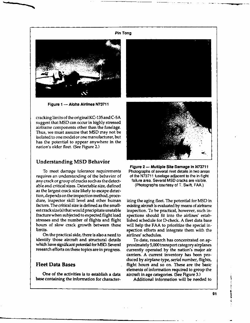
Pin Tong
Figure 1 - Aloha Airlines N73711
cracking limits of the original KC-135 and C-5Asuggest that MSD can occur in highly stressedairframe components other than the fuselage.Thus, we must assume that MSD may not beisolated to one model or one manufacturer, buthas the potential to appear anywhere in thenation's older fleet. (See Figure 2.)
Understanding MSD BehaviorFigure 2 - Multiple Site Damage in N73711
To meet damage tolerance requirements Photographs of several rivet details in two areasrequires an understanding of the behavior of of the N73711 fuselage adjacent to the in-flightany crack or group of cracks such as the detect- failure area. Several MSD cracks are visible.able and critical sizes. Detectable size, defined (Photographs courtesy of T. Swift, FAA.)as the largest crack size likely to escape detec-tion, depends on the inspection method, proce-dure, inspector skill level and other human izing the aging fleet. The potential for MSD infactors. The critical size is defined as the small- existing aircraft is evaluated by means of airframeest crack size(s) that would precipitate unstable inspection. To be practical, however, such in-fracture when subjected to expected flight load spections should fit into the airlines' estab-stresses and the number of flights and flight lished schedule for D-check. A fleet data basehours of slow crack growth between these will help the FAA to prioritize the special in-limits. spection efforts and integrate them with the
On the practical side, there is also a need to airlines' schedules.identify those aircraft and structural details To date, research has concentrated on ap-which have significant potential for MSD. Several proximately 5,000 transport category airplanesresearch efforts on these topics are in progress. currently operated by the nation's major air
carriers. A current inventory has been pro-duced by airplane type, serial number, flights,
Fleet Data Bases flight hours and so on. These are the basicelements of information required to group the
One of the activities is to establish a data aircraft in age categories. (See Figure 3.)base containing the information for character- Additional information will be needed to
91

Second Annual International Conference on Aging Aircraft
120 1u 100MBER 80
0F
60AIRC 40RAFT 20
0
5 10 15 20 25 30 35 40 45 50 55 60 65 70 75 80 85 90THOUSANDS Or LANDINGS
Figure 3 - DC-9 Fleet Age StatusThe data reflect the fleet as of October 31, 1988. The DC-9 design goal was 45,000 landings, each
assumed to represent a maximum service pressure cycle on the fuselage.
further group these aircraft in subcategories aircraft. Preparation is underway for a prelimi-relating to MSD potential. The additional ele- nary survey of the commuter fleet by a team ofments include model and sub-model (down to independent experts. The objective of the sur-the level of significant differences in the pri- vey is to identify those models that may havemary structure) and, for each individual air- sufficient potential for cracking to warrantplane, a history of its major repairs and the implementation of a SID program. Over theimplementation of major structural AD and next six to nine months, the expert team will beservice bulletin actions. (See Table 1.) visiting about 17 manufacturers to review about
Other existing data bases such as the Serv- 59 aircraft models for this purpose.ice Difficulty Report (SDR) and aviation safetyanalysis system (ASAS) are being searched forthese kinds of information. Currently, the ATA Tear t,:. p Effectivenesshas an Airworthiness Assurance Task Forcewhich has formed various committees to look Anot. , area of research is to examine theinto data analysis problems. The Transporta- effectiveness of tear straps. The ability of teartion Systems Center (TSC) is a participant on straps to contain fuselage fracture precipitatedthe subcommittee to define thedata format and by MSD linkup is of great concern. The trans-what data is required for analysis. port fuselages in service today are damage
In thecoming years, thedatabasedevelop- tolerant in the meaning of the term as estab-ment will also be extended to the commuter lished by two decades of design practice.
92

Pin Tong
AGING AIRPLANE FLEET DATA BASE
* TYPE, SERIAL NUMBER, N-NUMBER, UTILIZATION HISTORY
* OWNER HISTORY
* SIGNIFICANT DIFFERENCES IN PRIMARY STRUCTURES
* IMPLEMENTATION OF AD AND SB ACTIONS
* SDR - P REPAIR HISTORY
-1- TOWARDS A FLEET HEALTH MONITORING SYSTEM
Table I - Aging Airplane Fleet Data Base
(Thomas Swift, "Damage Tolerance in Pressur- nent tests. A special fixture presently underized Fuselages," 11th Planterna Memorial construction (Figure 4), will accommodateLecture, 14th symposium of the ICAO, Ottawa, curved panels which are 66 inches in circumfer-Canada, June 1987). Specifically, these structures ence by 120 inches axially. The fixture will beare able to contain up to a two-bay fracture at able to subject the panels to pressure loading,110 percent of design maximum pressure. In plus small amounts of shear and/or bending.other words, the damage tolerance require- Over the next few months, several simulatedment really is focused on protection against MSD fracture tests will be performed on thisisolated damage. (See Figure 4.) fixture. (See Figure 5.)
The objective of the present research is todetermine how effectively tear straps can con-tain a fracture in the presence of MSD. The Improved Analysis Methodsgeneral scenario assumes a fracture resultingfrom a linkup of a group of MSD cracks. The Another area of research is to improvefracture in this case lies along a skin splice, analysis methods. Fracture analyses of stiff-rather than in the middle of the bay, as is ened panels have been used Lo correlate testusually assumed in present design practices. data and predict design performance over twoIn the MSD scenario, the fracture is assumed to decades. The models most widely used forbe advancing toward adjacent bays which these analyses are based on the so-called dis-contain additional MSD cracks. (In broad out- placement compatible method (Thomas Swift,line, the scenario resembles the adjacent panel 'Damage Tolerance in Pressurized Fuselages,"cracking considerations raised during Air Force 11 th Planterna Memorial Lecture, 14th sympo-structural integrity assessments of the C-5A sium of the ICAO, Ottawa, Canada, June 1987)and C/KC-135 wings.) by our chairman, Tom Swift, and others.
The subject of tear strap effectiveness will But recent work has shown that advancedbe investigated by means of full-scale compo- finite element methods (P. Tong, "A Hybrid
93

Second Annual International Conference on Aging Aircraft
ALL RESIDUAL STRENGTH TESTS ,PERFORMED SO FAR FOR THETWO-BAY CRACK CASE HAVE BEENWITH CRACK TIPS IN PARENTMATERIAL
C7
- -TESTS ARE NEEDED FOR
THE TWO-BAY CRACKCASE WHERE CRACKTIPS ARE IN LINE WITHA ROW OF FASTENERHOLES AS IN LOCATION B
RESIDUAL STRENGTH TEST WITH CRACKS IN LINE WITHROW OF CHORDWISE HOLES
Figure 4 - Airframe Structural Integrity Program
Figure 5 - End-view Details of Test Fixture
94

Pin Tong
Finite Element Method for Damage Tolerance the curvature interacts with cracks to affectAnalysis," Computers and Structures, Vol 19, properties such as fracture resistance. Flat panelNo 1-2, pp. 263-269,1984) can provide equal or models must, therefore, be empirically cali-better results more efficiently. Both the panel brated by comparison with curved panel testsdisplacement method and the finite element in order to predict fracture resistance and cor-methods are able to model realistically the con- rection factors. The correction factors previ-struction details such as stringers and frame ously developed are valid for single bay cracks.offsets, load transfer through rivets, load trans- To establish similar factors for MSD wouldfer through bond and fastener or bond flexibili- require equally extensive testing.ties. The ability to do so is the result of years of The research objective in this case is toresearch effort. This model's ability carries over develop better analysis methods to account forto the MSD situation because the basic struc- curvature effects based on established prin-tural details do not change. (See Figure 6.) ciples of mechanics. The field of computation
Conversely, the ability to model the curva- mechanics has advanced considerably sinceture of the fuselage panel requires further re- the flat panel models were developed. It is nowsearch to make the extension to MSD, because possible to apply these advances to develop a
FINITE ELEMENT APPROACH
i ,.
-. . ..
1-J.-',1.-.
_iII +., I " ,
6 I I 5Ii r .
Figure 8 - Airframe Structural Integrity Program
95
Second Annual International Conference on Aging Aircraft
curved panel model. The type of behavior which Preliminary tests and the calculations basedcan noW be incorporated in the model includes on the N-73711 experience show that MSDbulging near the cracks and plastic collapse, must be detected at very small crack lengths
The development of curved panel models and in much shorter time than an isolated longwas started recently, and preliminary results crack, if MSD is to be found and repaired beforeshould be available in one year. Curved panel linkup and fracture occurs.fracture resisiance analysis will still require The detection requirements for MSD basi-checking against test results. However, model cally preclude reliance on thevisualinspection.validation should proceed rapidly because of The only alternative which has been reduced toreduced dependence upon the empirical corre- practice in the airlines' maintenance shop andlation. repair stations involves use of hand-held eddy
current probes. The eddy current method, aswe all know, is tedious to apply and can lead to
Basic Fracture Resistance human factors problems.
Another element of research is to define thefracture resistance characteristic. A better un- Nondestructive Inspectionderstanding of the basic fracture resistantproperty is required in order to predict the re- Better nondestructive inspection (NDI)sistance of a panel to MSD linkup. Panel frac- methods must be sought to arm the airlinesture predictions are currently made by means with procedures that are both proper and eco-of R-curve methods, which account for the fact nomical for MSD. The FAA and NASA havethat a crack in the thin ductile skin can extend been pursuing complementary programs inat stress levels below the fracture stress. The the NDI area. The details of this program willdata from which the R-curves are derived come be discussed in a session specifically devoted tofrom tests of wide panels containing large ini- NDI.tial cracks. These results are applicable to con- But I want to discuss an alternative to NDI,ventional damage tolerance assessments, but the so-called pressure proof test. Proof testingrecent calculations based on the N-73711 acci- was recently proposed as an interim means todent suggest that MSD fracture resistance protect the safety of certain older airframesestimates based on the conventional R-curve which are deemed to have high MSD potential,are not conservative, until terminating actions specified by air-
Therefore, laboratory test programs have worthiness directives have been taken on thosebeen started to investigate the possibility of airframes. The proposal calls fora one-time testderiving the special R-curve for MSD situ- in which a fuselage would be pressurized toations. The objective of a better understanding 1.33 times its maximum design pressure differ-for the MSD situation should be obtained in ential.about one year. (See Figure 7.) Proof testing is designed to eliminate the
uncertainty of NDI. If the structure does notfail, when loaded to the proof test level on the
How to Inspect for MSD ground, then fracture mechanics can be used toevaluate a safe interval for further flying be-
Just as Ulf Goranson showed in one of his cause passing the test establishes a precisefigures, there is no reason why a modem airframe upper limit on the size of any cracks which mayshould not continue to be flown indefinitely, be present.provided that it is properly maintained and The concept is certainly valid at large ratiosinspected. I think the last part of the statement of proof load to maximum service load, butis the key phrase, when we come to consider froma practical point of view, the ratio has tobethe implication for aging airframes with MSD limited by the need to avoid the damage topotential. adjacent structures during the test. Also, stable
96

Pin Tong
crack extension or even MSD linkup without alarge fracture during the test may not give anyobvious signs that something has happened.
The FAA is evaluating the fuselage pres-sure proof testing proposal. An analytic damagetolerance assessment was recently completedand is being reviewed by the oversight groupon aging aircraft.
Curved panels will also be fabricated forexperimentation on other aspects of the ques-tions raised about proof testing structures withMSD. The proof test evaluation work is ex-pected to be complete in four months.
How to Design for MSDResistance
Besides responding to the problems associ-ated with MSD potential in the existing fleet,the FAA research program also has the objec-tive of fostering improvement of design andfabrication practices to avoid MSD in the fu-ture. The goals apply to repairs as well as tonew design.
A conceptual model has been developed toprovide a quantitative ranking of the MSD po-tential of competing design and details. Theresearch will be continued in the direction ofexperiments in which MSD is induced in simu- Figure 7 - Simulated MSD Coupon Specimenlated design details. The development is ex-pected to take 18 to 24 months.
repairs will be used to identify critical designRepair Practices variables and their damage sensitivities. The
analyses will be validated by means of flat andAnother aspect of the research concerns curved panel tests. The validated models will
repair. Many major repairs to airframes are then be used to produce design charts for thedesigned to be installed by the airline mainte- handbook. The target date for completing thisnance repair station personnel. The repair handbook is October 1992.designs generally have static strength equiva- A part of the activity will also examine thelent to the original airframe's static strength. question of whether terminating actions suchSuch repairs can induce subsequent fatigue as specified in the 737 fuselage splice AD aredamage in adjacent areas unless they are de- fully terminating. It has been suggested thatsigned for damage tolerance as well as static fatigue cracking might reappear in a repairstrength. However, the maintenance organiza- splice (perhaps at the fastener row not in-tions are not equipped to conduct elaborate volved in the original MSD).damage tolerance assessments. The research The question is open, of whether reappear-objective in this area is to provide a handbook- ance of MSD should be expected in the remain-type of guideline for damage tolerance repair ing service life of the airplane. Tests of flatdesign. Fracture mechanics analyses of typical panels simulating pre-AD service, the repair,
97

Second Annual International Conference on Aging Aircraft
and post-AD service will be conducted to an- addresses a major issue which was raised byswer this question. Results are expected in the N-73711 accident. We hope that industryabout 18 months. will study the program results, as they are
developed, and take the final step to reducethose results to practice for specific designs and
Concluding Remarks maintenance actions.We invite you to hear the first detailed
The present research effort is directed by report on results at a symposium on structuralthe FAA Technical Center and the key staff of integrity of aging airplanes, sponsored by thethe research team at TSC, including Dr. Orrin- FAA Technical Center, and which will be hostedgar, Dr. Sampath, and Mr. Bobo. The work is by Georgia Tech in Atlanta, Georgia, on Marchalso supported by many independent experts 20-22, 1990. The symposium will cover theincluding the Technical Oversight Group on topics of mechanics of MSD, damage toleranceAging Airplanes (TOGAA) and other research of structures with MSD, structural integrity oforganizations such as FractuREsearch, Foster commuter airplanes, effects of corrosion onMiller, ADL, Battelle, SRI, and several structural integrity, repair, maintenance, lifeuniversities. enhancement schemes and life prediction meth-
The FAA research on aging airplanes, par- odologies.ticularly MSD, is fast-paced and realistic. It
98

Proof Testing of Pressure Cabins
J. BEN DE JONGE
Netherlands National Aerospace Laboratory (NLR)
I would like to give you a brief review of sons why one might consider the usefulness ofresearch on the topic of proof testing that is proof testing as an alternative inspection method.currently carried out at our laboratory under Proof testing cannot be called a non-contract with the Civil Aviation Department in destructive testing method, but it is not a purelythe Netherlands. I would also like to give a brief destructive testing method either. It is a verystatement of the reasons why one might con- peculiar type of testing. It saves good struc-sider proof testing of pressured cabins. I will tures and it destroys the bad ones. But, fortu-discuss briefly some of the associated prob- nately, it does that on the ground and not in thelems, potential problems, and the open ques- air, and that is an essential point.tions there are, followed by a review of NLR's Actually, the cabin is well-suited for prooftest program that we have carried out in the testing in the first place. The proof loading andbeginning of the year. its normal maximum is well defined. Loading
Why consider proof testing? As has been is relatively easy. You only need a pump andbrought up on several occasions today, the perhaps a piece of rope to bind the valves.aging aircraft cabin structure is prone to mul- And asan additional advantage, proof loadtiple site damage because of the repetitive nature may considerably retard or even stop the growthof the structure itself, the uniform loading of of existing cracks. We will come back to thatthat structure, and also the relatively low number later.of load cycles for which the structure is actually However, there are a number of associateddesigned to, 100,000 cycles, make it a kind of problems and questions, (see Figure 1). In thelow-cycle fatigue that is associated with rela- first place, one might consider the possibilitytively little scatter. For that reason, you may that rather than retarding the crack, you mayexpect multiple site damage. also have a crack jumping, a static crack exten-
It is clear that the inspection for multiple sion during your proof loading so that after thesite damage becomes increasingly difficult, proof loading you have actually a more dam-complicated and expensive and these are rea- aged structure than before the proof loading.
99
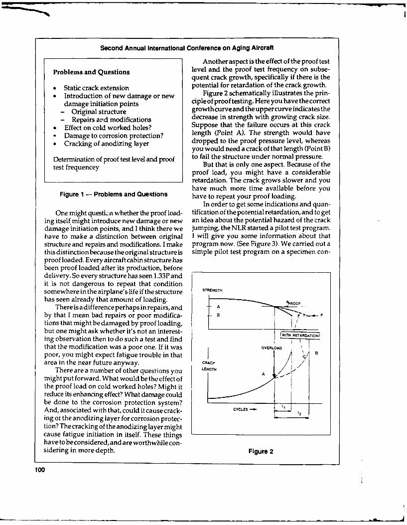
Second Annual International Conference on Aging Aircraft
Another aspect is the effect of the proof test
Problems and Questions level and the proof test frequency on subse-quent crack growth, specifically if there is the
* Static crack extension potential for retardation of the crack growth." Introduction of new damage or new Figure 2 schematically illustrates the prin-
damage initiation points ciple of proof testing. Here you have the correct
- Original structure growth curveand the upper curve indicates the
- Repairs and modifications decrease in strength with growing crack size." Effect on cold worked holes? Suppose that the failure occurs at this crack- Damage to corrosion protection? length (Point A). The strength would have
" Cracking of anodizing layer dropped to the proof pressure level, whereasyou would need a crack of that length (Point B)
Determination of proof test level and proof to fail the structure under normal pressure.test frequencey But that is only one aspect. Because of the
proof load, you might have a considerableretardation. The crack grows slower and youhave much more time available before you
Figure 1 - Problems and Questions have to repeat your proof loading.In order to get some indications and quan-
One might questi,.n whether the proof load- tification of the potential retardation, and to geting itself might introduce new damage or new an idea about the potential hazard of the crackdamage initiation points, and I think there we jumping, the NLR started a pilot test program.have to make a distinction between original I will give you some information about thatstructure and repairs and modifications. I make program now. (See Figure 3). We carried out athis distinction because the original structure is simple pilot test program on a specimen con-proof loaded. Every aircraft cabin structure hasbeen proof loaded after its production, beforedelivery. So every structure has seen 1.33P andit is not dangerous to repeat that conditionsomewhere in the airplane's life if the structure STRENGTH
has seen already that amount of loading.There is a difference perhaps in repairs, and A _-
by that I mean bad repairs or poor modifica- B Ptions that might be damaged by proof loading,but one might ask whether it's not an interest-ing observation then to do such a test and find ITI ON
that the modification was a poor one. If it was OVERLOAD /poor, you might expect fatigue trouble in thatarea in the near future anyway. cAcY /%/
There are a number of other questions you LENGTH A -
might put forward. What would be the ef fect ofthe proof load on cold worked holes? Might itreduce its enhancing effect? What damage couldbe done to the corrosion protection system?And, associated with that, could it cause crack- CYCLESing ot the anodizing layer for corrosion protec-
tion? The cracking of the anodizing layer mightcause fatigue initiation in itself. These thingshave to be considered, and are worthwhilecon-sidering in more depth. Figure 2
100
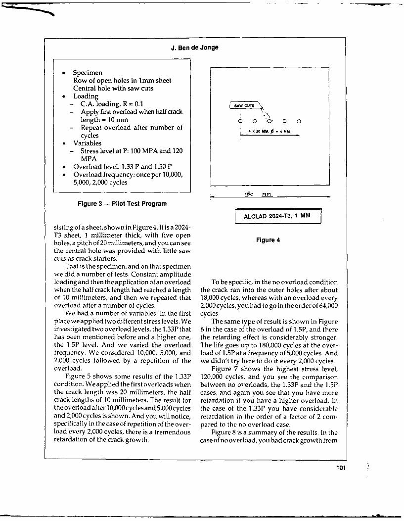
J. Ben do Jonge
* SpecimenRow of open holes in lmm sheetCentral hole with saw cuts
* Loading- C.A. loading, R = 0.1- Apply first overload when half crack
length = 10mm ( a- Repeat overload after number of
cycles I x2ou..4MM* Variables
- Stress level at P: 100 MPA and 120MPA
* Overload level: 1.33 P and 1.50 P* Overload frequency: once per 10,000,
5,000, 2,000 cycles
160 MM
Figure 3 - Pilot Test Program
ALCLAD 2024-T3, 1 MM
sisting of a sheet, shown in Figure 4. It is a 2024-T3 sheet, 1 millimeter thick, with five openholes, a pitch of 20 millimeters, and you can see Figure 4the central hole was provided with little sawcuts as crack starters.
That is the specimen, and on that specimenwe did a number of tests. Constant amplitudeloadingand then theapplication of an overload To be specific, in the no overload conditionwhen the half crack length had reached a length the crack ran into the outer holes after aboutof 10 millimeters, and then we repeated that 18,000 cycles, whereas with an overload everyoverload after a number of cycles. 2,000 cycles, you had to go in the order of 64,000
We had a number of variables. In the first cycles.place we applied two different stress levels. We The same type of result is shown in Figureinvestigated two overload levels, the 1.33P that 6 in the case of the overload of 1.5P, and therehas been mentioned before and a higher one, the retarding effect is considerably stronger.the 1.5P level. And we varied the overload The life goes up to 180,000 cycles at the over-frequency. We considered 10,000, 5,000, and load of 1.5P at a frequency of 5,000 cycles. And2,000 cycles followed by a repetition of the we didn't try here to do it every 2,000 cycles.overload. Figure 7 shows the highest stress level,
Figure 5 shows some results of the 1.33P 120,000 cycles, and you see the comparisoncondition. Weapplied the first overloads when between no overloads, the 1.33P and the 1.5Pthe crack length was 20 millimeters, the half cases, and again you see that you have morecrack lengths of 10 millimeters. The result for retardation if you have a higher overload. Intheoverloadafterl0,000cyclesand5,000cycles the case of the 1.33P you have considerableand 2,000 cycles is shown. And you will notice, retardation in the order of a factor of 2 com-specifically in the case of repetition of the over- pared to the no overload case.load every 2,000 cycles, there is a tremendous Figure 8 is a summary of the results. In theretardation of the crack growth. case of no overload, you had crack growth from
101

Second Annual International Conference on Aging Aircraft
10000 CYCLES 5000 CYCLES
NO OVERLOAD 1 J2000 CYCLES
OVERLOAD
-_____1.33 P
STRESS 100 MPa
. . . . ,- ,_-
0 10000 20000 30000 40000 50000 60000 70000
CYCLES
Figure 5
N 10000 5000
N)OVERLOAD CYCLES --- CYCLES
_ _ VELOAD 1.5 p
-Ik
2U SN g o Io 1200 I O 'SO
CYCLES ."0
Figure 6
102

J. Ben de Jonge
NO 1.33 P 1.50 P4 OVERLOAD- 500 CYCLES 5000 CYCLES - -
AL
0 5000 10000 15000 20000 25000 30000 35000
CYCLES -
Figure 7
OVERVIEW OF MAIN TEST RESULTS
STRESS PROOF PROOF CRACK GROWTH (CYCLES)LEVEL LOAD LOAD FROM A= 10 MM TO 42 M
LEVEL FREQUENCY
10OMPA 1901.33P 10000 /Z/ 90
50003202000 7777 20
1.50P 10000 7- 601.50P 5000//A 1QO
120 MPA 701.33P 50001201.50P 5000 m \1 kx 1 3001.50P 2000 h\40000
Figure 8 - Overview of Main Test Results
103

Second Annual International Conference on Aging Aircraft
10 millimeters to 42 millimeters, in the order of test level. Our design limit load is 1.33P, and19,000 cycles, and that increased with over- the design ultimate load is 2.OOP. With regardload. And the more often you apply the over- to the fail-safe load, there is little differenceload, the more retardation you have. If you between the FAR requirements and the JARapply an overload every 2,000 cycles it results requirements. And every new cabin is proofin a considerable increase in retardation. tested up to 1.33P. I understand that that's
I have to stress, of course, that these are standard practice, although it's not actually invery preliminary results. This was a very unre- the requirements.alistic configuration, just open holes, but I wanted We have to keep in mind that we expectto give you some feeling about the amount of every undamaged structure to be able to with-retardation that can be expected. And with stand the ultimate load or to withstand 2.OOP.regard to the crack jumping, we did not ob- We also say, and it came up also in Ulf Goran-serve any at all. You might have seen that also son's presentation, whenever damage is foundfrom the figures. The way the crack ran into the in a structure that might reduce the strengthnext hole was not influenced by the proof below ultimate load, or in this case below 2.OOP,loading at all. we must effect repairs. And in any case, it's
The results of this elementary series of tests normal practice that we expect every structureshowed important retardation due to over- to be, in all conditions, able to withstand theloads and no static crack extension was ob- limit load, and, in this case that would be 1.33P.served. We feel that these test results justify If you consider these things, you would sayfurther research in the viability of proof testing. there is no reason to be afraid of applying, now
At NLR we have plans to continue this test and then, that 1.33P load to your structure justprogram in the near future and we intend to do to show that it is able to withstand what youtests on more representative configurations expect from the structure.such as riveted lap joints of larger-scale with Proof testing may offer an interesting alter-natural crack initiation to include real multiple native to other inspection methods. We feelsites damage situations, and in those condi- that our pilot test results support its potentialtions we would again investigate the effect of usefulness, and we feel that further investiga-proof loading on the retardation effect. tions are required to get the answer to the
The next step will then be to investigate, potential problems that we defined.and to do the same type of tests by actual My recommendation is to try and coordi-loading to see whether that has any influence nate the worldwide R&D efforts on this subjectwhich could be the case. Then there is the so that we do not repeat or carry out the samepossibility to extend that testing to the condi- tests. Let's try to find some coordination in thistion of curved panels under biaxial loading, area. I think the results should become avail-with pressurization. able as soon as possible as we might need that
That's enough about the test program. I type of alternative test procedure.would like to say a few things about the proof
104

Session II: Loads
CHAIRMAN TERENCE J. BARNES
FAA National Resource Specialist
I am honored to be chairing this session and onto the early data base that we had, which wasam pleased to present three very qualified pre-1982. The data base was mostly pre-jet andspeakers for you today. Tom DeFiore of the mostly pre-deregulation.FAA Technical Center will be followed by We have the potential, after collecting theNASA's Norm Crabill. The third presentation data, to improve our design criteria.will be by Ben de Jonge who spoke yesterday in It's possible that we may be able to deter-Tom Swift's session. mine more precise inspection requirements.
Since this year the specialist sessions are We can validate our test spectra and somerunning sequentially, so all the conference at- other items which are fallouts of this type oftendeesareable tobepresentatall thesessions. program, and we can avoid operating airplanesFor this reason, and because this is the first time in particularly severe environments, if this isthat we have had this subject, "Loads," I've possible. Furthermore, we have the opportu-elected to take just a few minutes to explain nity to investigate flight incidents that may beexactly what we are doing in this session. abnormal.
As you will hear from Norm Crabill later, Figure I is included so that everyone canwe had a NASA program which was abruptly understand how we plan to get reliable loadsstopped in 1982. (This is probably a good point data from relatively simple measured parame-to tell you that in this program we're not actu- ters. I'd like to point out that the key to thisally going to measure loads. We're actually whole process is actually in the hands of thegoing to measure more measurable items such manufacturer.as altitude, speed, CG acceleration, et cetera.) When we look at design loads, we first get
What we are planning to do now is to build design flight load condition data. Airplane speed,
105
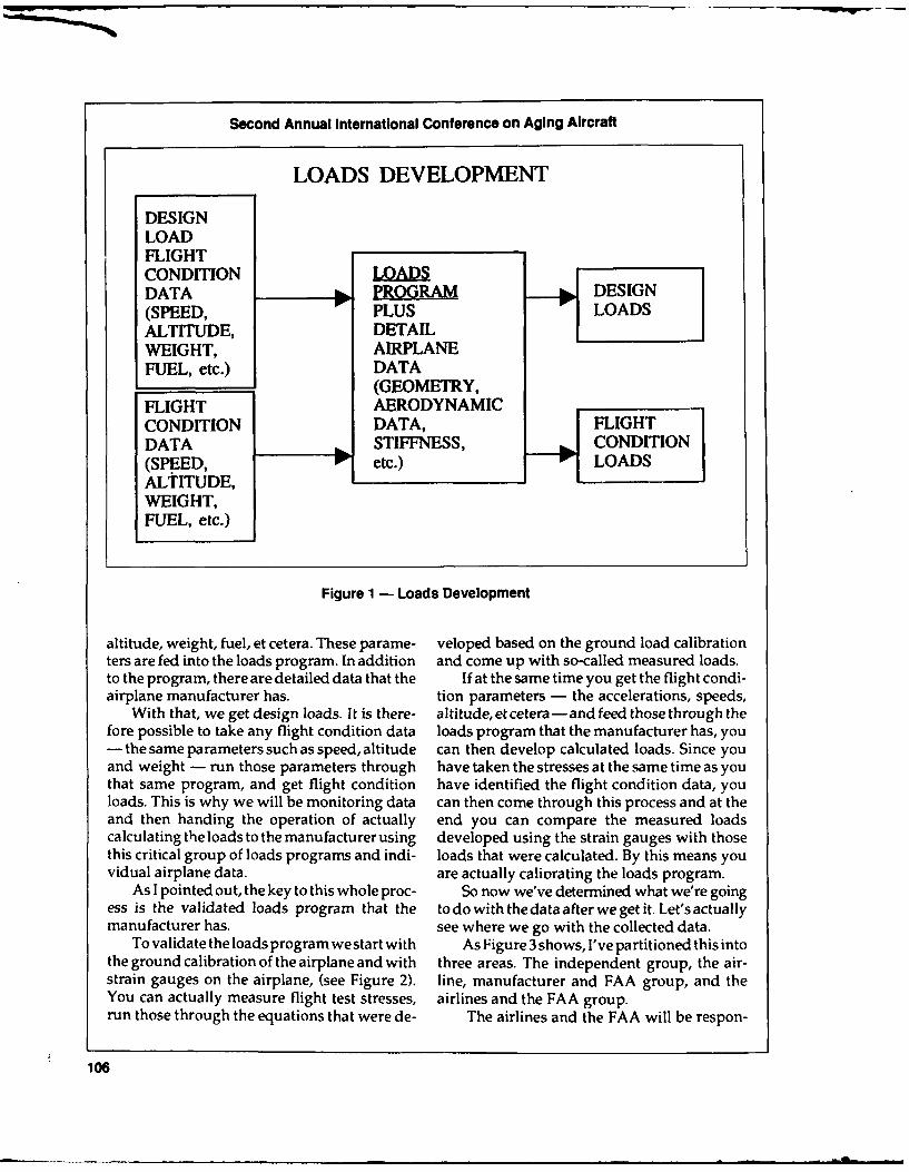
Second Annual International Conference on Aging Aircraft
LOADS DEVELOPMENT
DESIGNLOADFLIGHTCONDITION LOADSDATA PROGRAM o DESIGN(SPEED, PLUS LOADSALTITUDE, DETAILWEIGHT, AIRPLANEFUEL, etc.) DATA
(GEOMETRY,FLIGHT AERODYNAMICCONDITION DATA, FLIGHTDATA STIFFNESS,(SPEED, etc.) LOADSALTITUDE,WEIGHT,FUEL, etc.)
Figure 1 - Loads Development
altitude, weight, fuel, et cetera. These parame- veloped based on the ground load calibrationters are fed into the loads program. In addition and come up with so-called measured loads.to the program, there are detailed data that the If at the same time you get the flight condi-airplane manufacturer has. tion parameters - the accelerations, speeds,
With that, we get design loads. It is there- altitude, etcetera -and feed those through thefore possible to take any flight condition data loads program that the manufacturer has, you- the same parameters such as speed, altitude can then develop calculated loads. Since youand weight - run those parameters through have taken the stresses at the same time as youthat same program, and get flight condition have identified the flight condition data, youloads. This is why we will be monitoring data can then come through this process and at theand then handing the operation of actually end you can compare the measured loadscalculating the loads to the manufacturer using developed using the strain gauges with thosethis critical group of loads programs and indi- loads that were calculated. By this means youvidual airplane data. are actually caliorating the loads program.
As I pointed out, the key to this whole proc- So now we've determined what we're goingess is the validated loads program that the to do with the data after we get it. Let's actuallymanufacturer has. see where we go with the collected data.
To validate the loads program we start with As Figure 3 shows, I've partitioned this intothe ground calibration of the airplane and with three areas. The independent group, the air-strain gauges on the airplane, (see Figure 2). line, manufacturer and FAA group, and theYou can actually measure flight test stresses, airlines and the FAA group.run those through the equations that were de- The airlines and the FAA will be respon-
106

Terence J. Barnes
TYPICAL LOADS PROGRAM VALIDATION
FLIGHT STRESS/LOAD "MEASURED"TEST RELATIONSHIPS LOADS
STRESSES BASED ONGROUND LOADINGI CALIBRATION
AT SAME TIME COMPARE
FLIGHT LOADSTEST PROGRAM CALCULATED
CONDITION PLUS LOADSDATA DATA
Figure 2- Typical Loads Program Validation
COLLECTED DATA FLOW - STEP I
INDEPENDENT GROUP
MEASUREDACCELERATIONS -p, REMOVE
ETC. REVIEW SPECIFICDATA FLIGHT
AIRPLANEPARAMETERSSPEED,
WEIGHT,ALTITU1DE,ETC. ..
REVIEWSPECIALEVENTS
AIRLNES AIRLNEFAA MANUFACTURER
FAA
Figure 3 - Collected Data Flow - Step 1
107

Second Annual international Conference on Aging Aircraft
sible for collecting the data. All the data then At each one of these stages the data that wewill go to this independent group which will get will be fed back to the FAA in order toreview the data. If there are any special events produce the statistics.that are of interest, they will be fed back to a The manufacturer with the data producesgroup comprised of airline, manufacturer and component loads, and with the validated stressFAA representatives to review the special events, analysis program and detailed design data, the
Once these have been satisfactorily reviewed, manufacturer can now develop the componentthe data will go back into the package. The stresses. (See Figure 5)independent group will remove specific flight At this point I would like to tell you thatidentification and then we can start work. from the start of monitoring data we won't
Figure 4 shows the independent group with expect instant results. Rather than a couple ofall the data. The measured accelerations will be months we're looking at maybe a couple offiltered to separate gust and maneuvers. The years before we get some good data.maneuvers can then go back to the manufac- Another point is that we did put out aturer to be used in developing the component survey through ATA to the airlines and as ofloads using the validated loads program. last week we had two airlines that had re-
Filtering out the gusts, we will have gusts sponded favorably. One agreed to help usdefined as actual accelerations. Then, through develop the brass board data recorder andthe use of the airplane aerodynamic parame- another airline is willing to participate in theters, we can develop gust velocity, derived gust monitoring program.velocities, and these will also be fed to themanufacturer.
COLLECTED DATA FLOW - STEP 2
MEASURED MANEUVERSACCELERATIONS VALIDATED
ETC. FILTER LOADSPROGRAM
GUSTS ANDDETAIL
AIRPLANEAAIRPLANE DATA
PARAMETERS AEROSPEED, PARAMETERSWEIGHT, ETC.ALTITUDE,ETC.
STATISICS COMPONENTLOADS t
INDEPENDENT FAA MANUFACTURERGROUP
Figure 4 - Collected Data Flow - Step 2
108

Terence J. Barnes
COLLECTED DATA FLOW - STEP 3
VALIATEDSTRES
ANALYSISCOMPONENT PROGRAMCOPNT
LOADS & SRSEDETAILDESIGNDATA
MANUFACTURER
Figure 5 - Collected Data Flow - Step 3
109

Flight Load Data Collection
THOMAS DEFIORE
Flight Loads Program Manager, FAA Technical Center
Good morning. It's a pleasure to be here to FAA National Resource Specialist on flightspeak with you to describe our plans for rees- loads and aeroelasticity, FAA Headquarterstablishing the flight loads data collection (AIR-107) which provides the support, the FAAprogram. Technical Center, engineers who are the pro-
My briefing today will cover some of the gram manager for the effort, and NASA whochronology and activities that we've been in- conducted the prior U.S. flight data collectionvolved in in reestablishing our program. I am efforts.going to provide a functionaldescription of our We've added the membership of the ATAplanned new flight data recorder, and con- and the Flight Safety Foundation in August ofclude with some comments and concerns re- this year. Mr. Dick Tobiason has agreed to begarding the program integration, the ATA focal point with the airlines for the
The purpose of the program is to reactivate development of this program.the flight loads data collection effort by devel- Some of the future membership in ouroping and installing a state-of-the-art flight working group will consist of loads engineersdata recorder in transport aircraft: the objective from the aircraft manufacturers, the airlines,of which is to collect and analyze commercial and AIA/ARINC responsible for the data bussesaircraft in-service flight data and to provide on the aircraft, and the National Transporta-survey data on a continuous basis for airframe tion Safety Board who have a lot of experiencemanufacturers to review and assess whether in analyzing and handling flight data.typical operating load spectra used in design The contractual support summary for ourare representative for the jet transport fleet, program appears in Figure 2. Our initial planand, to develop structural design criteria for was to draw on all the prior experience in U.S.future generations of aircraft. In order. to ac- transport flight loads data collection, most ofcomplish these objectives we've established which resides at NASA Langley. We negoti-someworkinggroups. (SeeFigurel)Theinitial ated an interagency agreement with NASA inworking group consisted of Terry Barnes, the the spring of 1989. This actually involved the
110

Thomas DeFiore
Initial Support
FAA NRS * Interagency agreement (NASA)FAA HQTS - Eagle Engineering
FAA Tech Center * Flight test and aviation enterprisesNASA * Competitive procurement for 24
flight recordersAdded 0 Data reduction and analysis
ATAFSF
Figure 2 - FAA New Flight Loads DataFuture Collection Program
Aircraft Manufacturers bility to handle the volume of data we expectAirlines from the 24 recorders.
AIA/ARINC This reactivation of the flight loads pro-NTSB gram has been a part of the FAA's aging aircraft
program plan from the initial draft back inNovember 1988. Industry supports this effort.
Figure 1 - FAA New Flight Loads Data At the March 20-21, 1989 R&D task unit meet-Collection Program - Working Groups ing, flight loads was identified as one of the
R&D items for aging aircraft.The R&D task unit recommended a five-
transference of funds for these specific tasks. year data collection program, the purpose ofThis agreement is independent of the memo- which is to update the data base from the earlyrandum of agreement for joint research be- 1960s. This scope of effort corresponds withtween NASA and the FAA for the aging aircraft what we have planned at this time.signed just one week prior to this conference. Some of the chronology of our activities
Eagle Engineering, staffed with a number since the March 20-21 R&D summary areof former NASA personnel involved in the summarized in Figure 3. A program initiationprior flight load data collection programs, is and development session was conducted atproviding some of the direct support. NASA in March 1989. In April, we conducted a
Our own local contractor, Flight Test and workshop at the FAA Technical Center involv-Aviation Enterprises, are our consultants for ing, again, all prior flight loads data collectioninstrumentation. engineers.
We plan two additional procurements over We had an aircraft manufacturer briefing atthe next year or two. The first one will be a Boeing to explain our proposed program. Wecompetitive procurement for the 24 flight load received meaningful feedback indicating thedata recorders which we expect to install in the kind of program that would be most beneficialtransport aircraft along with a ground station for the industry.for data transcription. The second procure- We recently conducted the ATA and Flightment is planned to be a data reduction and Safety Foundation briefing where we foundanalysis contract to analyze the recorded fleet more ATA support for the program than wedata. had originally expected.
At the FAA Technical Center we have in- Currently, we are in the process of an inten-stalled a new IBM 4381 computer mainframe sive effort in the systems design. The nextwhich has more than enough processing capa- speaker, Norm Crabill, and I will be the co-
111 i

Second Annual International Conference on Aging Aircraft
Location/Sponsor Purpose Date
ATA Industry R&D 21 March 1989
NASA HQTS Program Initiation 31 March 1989
NASA Langley Program Development Meeting 17-18 April 1989
FAA Tech Center Workshop 3 May 1989
Boeing AC Manufacturer Briefing 13 June 1989
FAA HQTS ATA, FSF Briefing 22 August 1989
FAA/FSF Aging Aircraft Conference 3-5 October 1989
FAA Tech Center/NASA System Design Oct./Nov./Dec. 1989
ATA or FAA Working Group/Airline Introduction November 1989
McDonnell Douglas AC Manufacturer Briefing November 1989
Figure 3 - Program Activities
designers of the new data collection system, or data repository, of flight loads data andand we'll likely present this design at a future ultimatelybecomethecenterofinformationforconference in the spring or summer of 1990. the international flight loads data collection.
We are also planning to have another The longer term program efforts are forworking group meeting when we brief our NASA to develop and installa prototypesmartprogram to the airlines, data recorder in one revenue aircraft, to pur-
The schedule and program tasks and deliv- chase and install the 24 smart recorders overerables are listed in Figure 4. NASA refers to the next four years, (six recorders in each yeartasks within the scope of the Interagency Agree- 1991 through 1994) and to begin the task ofment. The initial task is to publish the reports collecting and analyzing data.for the prior NASA collected data on the four As Terry Barnes mentioned, we're not goingaircraft listed on the figure. While the aircraft to have any data immediately available formanufacturers have the reports for their par- analysis. January 1992 is the earliest likely dateticular aircraft, the data have not been pub- to get fleet data. Thus, flight loads data collec-lished in a formal report. tion is a long term aging aircraft effort.
The second task will be to publish a meth- Before I describe the proposed recorderods report. The intent is to document as much and what weexpect it to do, I do want to defineof the criteria and analysis, and assumptions the term "smart" recorder. A smart recorder isthat have been a part of both the U.S. and an on-board microprocessor-based system withforeign prior data collection programs. the capability of analyzing and making deci-
Wehavedraftcopiesofallfourdatareports sions on what data is meaningful to store forand the methods reports. These are in a final postflight evaluation.review process at this time and are due out The idea of using the smart recorder issoon. based on the availability and expanded capa-
The other short-term task is to acquire and bilities of off-the-shelf hardware. Some of thepublish all available flight loads data from characteristics of new recorders are listed inforeign carriers. This is part of the FAA Techni- Figure 5. We expect that they will have thecal Center's effort to become the data archive, ability to recognize the specific aircraft situ-
112

Thomas DeFlore
NEAR TERM 9 Recognize aircraft situation (climb,cruise, etc.)
" Publish report for NASA collected * Select appropriate data reduction al-data L-I011, B-727, B-747, and DC- gorithms10 (1978-1980) 0 Process data in real time (micro-10/89 (NASA) processor)
0 Reprogrammable & Upgradable" Publish Methods Report 0 No interference with flight operations
12/89 (NASA) 0 Applicable for transport and com-muter aircraft
* Acquire and publish flight loads data 0 Process/store large amounts of flightfrom foreign carriers data1290
LONG TERM Figure 5 - 'Smart' Recorder Characteristics
Develop prototype 'smart' data re- The recorders will be useable on both trans-9/90 (NASA) port and commuter aircraft, though it will bemore difficult to instrument commuters be-
* Purchase and install 24 'smart' cause they typically are not equipped with
recorders sophisticated data bases.12/91 We also expect to have the ability to trans-Six in each year (91, 92, 93, 94) fer data recorders from one airline to another,12/94 one plane to another and from one aircraft
category to another. The major benefit of this* Collect and analyze flight data new program is that we are going to be able to
1/92 process huge amounts of data in short periodsof time, especially when viewed in comparisonto some of the prior VGH data processing
Figure 4 - Program Schedule efforts.The proposed aircraft interface for trans-
ation, i.e., climb, cruise, taxi, landing, etc. Then, port aircraft is displayed in Figure 6. Beforebased on this situation, select the appropriate describing plans for the smart recorder datadata reduction algorithms. These can include acquisition, I want to describe how data wasmodifying the data sampling rate, changing acquired during NASA's recent DVGH survey.input parameters into the processing software The crash recorder, named the digital flightand modifying the processing algorithms which data recorder (DFDR), receives its data fromprovide the information that we need for flight three on-board sources: the flight data entrypath analysis. panels; the ARINC 429 data bus which pro-
All the data is expected to be processed in vides most of the flight and control surfacereal time. The recorders are going to be repro- information; and the three-axis accelerometer.grammable and upgradable, and there will be These three are fed into the digital flightno crash recorder requirement for the data data analyzer unit (DFDAU). This unit decidesstorage unit. There will be no interference with which parameters are to be stored on the crashthe flight operations. All the data we need for recorder and inputs that infornation into thethe flight recall will be self-contained on the crash recorder for storage. Prior survey datamemory storage unit which will be off-loaded was acquired by copying the 30 hours of dataperiodically, onto its own storage unit and then offloading
113

Second Annual International Conference on Aging Aircraft
FLIGHTDATA
ENTRYPANEL
(DIUITAL)
AIRCRAFT INTERFACE
A D DFDAU DFDR A SPRIOR, ... •SURVEY
32 IT RECORDER t
ACCELERO- DFDAU * lMICRO ] RECORDER
(ANALOG)
DFDAU (DIGITAL FLIGHT DATA ACQUISITION UNIT)
DFDR (DIGITAL FLIGHT DATA RECORDER)HIGHER SAMPLING RATES
Figure 6 - Aircraft Interface
these every three or four days whenever the Another design feature is that the smart re-storage unit was filled, corder will have to be offloaded only during the
We are planning to acquire our smart re- "B" level maintenance check, which occurscorder data in one of two ways: by picking up every 10 or 12 weeks. We plan to size ourour data immediately prior to it entering the recorder to store data from up to 500 points. IfDFDR or immediately prior to entering the the 500 seems a little bit small, then we'ddigital flight data analyzer unit. Part of our appreciate the feedback so we can know whatstudy is to determine which of these two meth- the proper sizing should be.ods is more cost effective. Choosing the former The data which we plan to collect are sum-method will require less hardware but it may marized on Figure 7. Some of the individualrequire costly additional software, while FAR parameters were available on prior surveys,Part 121 calls foraspecificminimumnumberof but never collectively as a group. These in-parameters for the crash recorder, a number of clude: typical flight path parameters, controlthe airlines have chosen to exceed that mini- surfaces, and individual flight data summaries.mum. It may turn out that we may need The output expected from the program asnumerous different software sets to accomo- presented in Figure 8, and to restate it: thedate the various airlines and this may not be entire process will be fully automated withcost effective. minimal airplane interface. All the data needed
Choosing the second method involves ac- will be on our data storage unit which will bequiring data prior to entering the FDAU. Since offloaded at the "B" level maintenance check.the ARINC 429 data for all airlines is similar, Some of the aircraft usage characteristicswe'll just need one set of software, though we that we will provide are listed on Figure 8.will need additional hardware. We hope to These include: typical flight profile statisticshave a decision on our system design shortly. such as frequency distributions, tables of flight
114

Thomas DeFiore
FLIGHT PARAMETERS 0 Accomplished by fully automateddata acquisition and ground com-
Fuel remaining puter processingAbsolute cabin pressureLongitudinal C.G. position 0 Aircraft usage characteristics (sum-Pressure altitude maries)Calibrated airspeed - Flight profile dataVertical acceleration - Acceleration statisticsLateral acceleration - Takeoff and landing parametersLongitudinal acceleration - Special eventsGear squat positionAutopilot status Aircraft in program
- Initially: B-737 (3), MD-80 (3)CONTROL SURFACES - Future candidates: B-747, B-757,
B-767, MD-11, A-320Flap positionSpoiler positionsRudder positionsAileron positions Figure 8 - Program OuputStabilizer positionsElevator positions The aircraft which we plan to incorporate
initially into our program, will be three B-737sFLIGHT SPECIFIC DATA and three MD-80s. Some of the future candi-
dates include: B-747, B-757, B-767, MD-11, andFlight origination code A-320, but we haven't firmed up our aircraftFlight destination code selections beyond the original six recorders.Date/time (takeoff and landing) The largest single benefit of using subject-Gross weight at takeoff smart recorders is the volume of data whichFuel load (takeoff, landing) can be collected. A comparison of the data
volume from the most recent NASA DVGHsurvey to what we expect from our new pro-
Figure 7 - Measured Data gram is presented on Figure 9. NASA's was atwo-and-a-half year program, and while I don'tknow specifically how many manhours or
duration, control surface usages, air speed, manyears were spent, they collected only aaltitudes; acceleration statistics for calculating little over 5,000 flight hours during their entireand measuring the maneuver loads and deriv- program. Our survey program with the new 24ing the gust velocities; takeoff and landing recorders will be expected to provide 30,000parameters, such as distributions of takeoff flight hours in just six months. As one can see,distance, takeoffvelocity, andlandingvelocity; when we implement our five-year data collec-and, if there is space available on our recorder, tion effort, the volume of data hours collectedspecial or unusual events. The United King- will leave no doubt as to what is the properdom Civil Aviation Authority (CAA) has a characterization of commercial aircraft fleet ormassive program called CAADRP with which service usage.they measure at least 25 structural related special I want to summarize with just a number ofevents. We plan to look at their program to see comments. Our program's primary goal is towhat parts of it might be applicable for U.S. collect and characterize typical fleet servicecommercial aviation, usage information and perform some investi-
115

Second Annual International Conference on Aging Aircraft
NASA DVGH survey (1978-1980): 0 Specific flight identification removedCollected and processed 5112 flighthours forL-1011,B-747, DC-10,andB- 0 Statistical flight data will be pub-
727 aircraft. lished
New flight loads survey: 0 Airline volunteers (ATA Focal Point)New 'smart' flight data recorders are - NASA prototypeexpected to provide 30,000 flight hours - First six "smart" recorders (B-737,in six months. MD-80)
Airline support
Figure 9 - Data Volume Comparison - Initial installation (kit)- Removal/replace data cartridge
(memory)
gation on the frequency of special or unusual - No flight log information required
events. We plan to eliminate specific flight - Inform FAA if system not
information. We don't want to know what day operating
or which pilot, we're interested in understand-ing only typical flight characteristics. We plan NOT a fatigue life assessmentto ask an independent party, such as NASA, programthe Flight Safety Foundation, or perhaps theATA, to review the data and remove specific Figure 10 - Concerns/Commentsflight identification data so that all we get is thestructural usage information. The resultant sta-tistical flight information and analysis will be beyond removing and replacing cartridges andpublished periodically. simply informing the FAA if the system isn't
We are looking for airline volunteers. The working, i.e., a look every now and then toATA's Dick Tobiason, has had some positive check if the right combination of green, red andfeedback from a couple of airlines willing to amber lights are blinking. If the system iswork with our NASA prototype installation malfunctioning, the FAA will make the neces-and one or two others interested in hosting the sary repairs.initial six recorders. We're planning a meeting The support for the NASA prototype sys-next month with the volunteer airlines and tem will probably involve more than what'sothers that are interested and we will provide listed on Figure 10, in that during the develop-a more detailed briefing of our program and ment process, we're going to need to see therequirements at that time. data more frequently than the "B" level 10-
The airline support that we need is listed in week interval.Figure 10. We'll provide a kit for installation I want to close with one final comment.and it's likely to be simple, involving just one This new program is not a fatigue life or struc-self-contained box no larger than two feet by tural life assessment program and we have noone half foot square. We'll provide installation plans on expanding it into one. Our primaryinstructions and ask the airline personnel to purposes, as I stated in the beginning, are toremove the data cartridges periodically, and provide data for the aircraft manufacturer toforward them to the FAA Technical Center. No assess how well the design and the fleet serviceflight log information will be needed whatso- usage correlate and to develop future designever. Airlines won't be asked to do anything criteria.
116

Structures Technology
NORMAN L. CRABILL
Aerospace Technologist, Eagle Engineering
I'm going to do a little bit of a retrospective. erometer, then, the VG recorder, which tracedIt is sometimes good to look back and consider velocity and accelerations directly on the de-what we did before, and how it relates to what signer's V-N diagram. That's the way you didwe are going to do in the future. So I'm going it in those days. You sketched out a V-N dia-to talk about the NACA/NASA Air Worthi- gram and built the airplane to it. Then youness Programs, including the loads program proofed the airplane against the V-N diagram.and the digital VGH program. So, theVGH time history approach was de-
Figure 1 is an overview of NASA in the veloped. It went on for quite a few years butNACA/NASA Operational Loads Program. was stopped in the late 1970s. The applicationAs you can see, there has been a long involve- of the digital VGH, or application of digitalment in airplane motions and loads, starting techniques to the VGH time history started inback in NACA Technical Report Number 1, by the late 1970s, then was terminated abruptly inHunsacker and Wilson, which looked at the 1982 just when we were really getting going.aircraft motions and their response to gusts. NASA has long been interested in gustThis was followed later by the Sharp EdgeGust loads, maneuver loads and ground loads. I'mResponse Analysis, the Gradient Gust Analy- not going to detail all the authors and theirsis and the cosine formulation. These were all reports since they are listed on the figure.for discrete gusts. The digital VGH program started in 1977
The generalized harmonic analysis tech- and we decided to use the digital flight datanique was then applied to estimate the re- typed from the crash recorder 25-hour loopsponses of airplanes in continuous turbulence tape. (See Figure 2) It was readily available ifand it was a fortunate thing because about that you were out there every two or three days totime airplanes started getting big and flexible. copy the tape before it got wiped out. But it had
Changes in measurement techniques fol- a lot of data, more than we could handle at thelowed. We used the state-of-the-art equipment time.every time. We started out with the basic accel- We started in 1977 with 15 tapes, pur-
117N

Second Annual International Conference on Aging Aircraft
SUMMARY OF NACA/NASA OPERATIONAL LOADSSURVEYS ON CIVIL AIRCRAFT
GRAD GUST .COS GUST
* ANALYSIS 3 NACA TR-I SE. GUST IlI
* MEASUREMENTS
* RECORDER
DATA GS LOADS
* AIRCRAFT
* SINGLE ENGINE 3 RHODE AND LUNDQUIST 1xv,PISTON I DOOLITTLE
TWIN-PISTON RHODE U RTI
LAND AND SEA WALKER AND STEINERPLANES DON'ELY
* PISTON, TURBOPROP LaRC AWB STAFF ]AND Ist GEN. JETS
COLE.MAN WLE
HUNTER
2nd GEN JET ZALOVCIK CRABILLI I I I
1910 1920 1930 1940 1950 1960 1970 1980 1990
Figure 1 - Surveys on Civil Aircraft
chased from an airline, of flights that were ing new data from several airlines covering themade in 1973, with about 200 hours of data to four airplane types. We got about 5,000 hoursdevelop the data acquisition techniques - such of data and we worked our way through thatas the operational techniques of getting the and then Phase 1-1/2, which included the grounddata from the airlines and all the flight log data operation parameters. We got data off ten flightsthat had to go with it because weights and so on an L-1011 on Phase 1-1/2.forth were not on the digital flight data re- Wedeterminedthatwecouldgetridofalotcorder tape. of manual labor if we did the processing on-
We developed a lot of analysis techniques, board before the data went to the crash re-and that meant editing every minute of it be- corder. We looked in real time at the bit stream,cause the transcription process of copying the and found that it was high quality data. It diddata from the flight recorder onto a copy tape not have all of the gaps and the duplicationswas fraught with all kinds of errors or prob- that we got from the copy recorder. Neitherdidlems, many of which we solved with a lot of it have the wild point spikes. Most of it wasmanpower. good clean data.
We went ahead with Phase I in 1978, buy- This meant the smart recorder approach
118

Norman L Crabill
landing roll was completed. This was a lot of
" Initiated 1977 fun but a lot of work, too.Figure 4 is an outline of the results from the
" Used DFDR data types (25 hour Phase 1 report. These data arebeing reported intape from "Crash Recorder") NASA CR-18-1909 which will be available
- "Readily" available shortly. We broke the data down into flight
- More data types [used 6 or 7 out profiles statistics and acceleration derived sta-
of available 19] tistics.These are generally broken down into per-
* Pilot Programs 1977-1978 - 200 cent of time or counts per hour - that is, on a
hours time basis - or percent of flights. We looked at- L-1 011 -15 tapes of various air- entire flights; that is, where the flaps were up or
craft flights in 1973 down, and we looked at flaps down only, and
- Developed techniques we looked at spoiler deflections. This break-- Data acquisition down can give you two things, the percent of" Analysis time at these gross weight and flight altitudes
for climb, level and descent, and percent of
* Phase 1.0 1978-1981: Flight Para- time at various air speeds and pressure alti-meters - 5000 hours tudes for climb, level and decent.
- L-1011 We looked at the weight at takeoff and- B-727, 747 landing as a percent of flights, and also maxi-- DC-10 mum pressure altitudes as a function of the
percent of flights.* Phase 1.5 1980-1982: GroundPar- The other categories include flap-detents
ameters - 10 flights usage in takeoff and landing per time. Gross- L-1011 weight, altitude above ground level, and air
speed versus flap-detents in takeoff and land-* Phase 2.0 1982-1985: SMART RE- ing, spoiler deflections versus calibrated air
CORDER - 200 hours speed and spoiler deflections greater than ten- King Air degrees with a function of altitude were statis-
tically analyzed.Acceleration derived statistics is another
Figure 2 - NASA Digital VGH Program category that is very important and is related to1977-1985 loads. We looked at total normal acceleration,
lateral acceleration, and from the normal wegot UDE counts.
was feasible, where you take the data in real Then, finally, with flaps down, we lookedtime, then reduce it down into the statistical at normal acceleration versus detent usage fordata-types and accumulate those as long as it's takeoff and landing.convenient. That is a considerable body of data, and the
Figure 3 are the parameters we took off the data reports, of up to 170 pages, are prettydigital flight data recorders in Phase 1. Phase 1 thick.was just the flight parameters, while Phase 1- Figure 5 is a simple sample of percent of1/2 included ground operation parameters. flights to maximum pressure altitude for an L-We added some data types over here that are 1011. As you would expect, most of the timenot normally carried on the DFDR. We found, was spent between 35,000 and 40,000 feet.for instance, that the nose wheel steering angle Figure 6 shows a portion of the flap study.was a real convenient indicator of when he got This shows percent of time in the flap detent inoff the runway. We looked at brake pressures percent of total flight time.and temperatures to help decide when the In the upper plot, we had about 14.2 hours
119
K ___aImmm mmmlr l• m m mnl ImI~lmimm
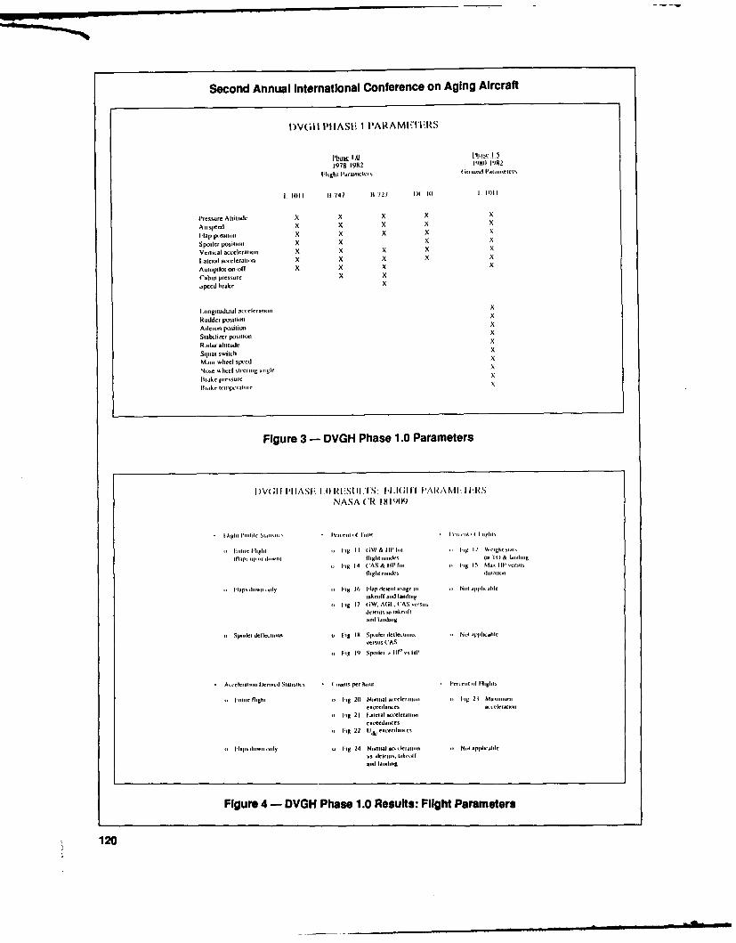
Second Annual International Conference on Aging Aircraft
IDV(;I PIIASI; I PARAMIi'IIFRS
1978 1982 1980 1992Htighit l'uurieier G tIiiti ('1 iaioit
li 1. I 1747 11 721 DCi 1) 1 li0t 1
lressure Aititiode x x X x
Airspeedt x X x x
H'ap potiii X X X X
Spoiter positiont x x x x
Vertical acceleration X x X x x
I ateral acecteliini X X X X x
Aut,,1utoi on-off x X 71 X
Cabin pressure 71 X
speedl brake X
Longitudinal accclerawe, X
Rudder positioni X
Aileron position X
Stabilizer positione xRadar altitude x
Squat smich 71
Main wheel sixed X
Ni,e wheel steering oirple x
liake pressurc x
Figure 3- DVGH Phase 1.0 Parameters
N ASA CR 18 1909
tuor M-igt 1 lHg I I tGt
& Ill It ti I 1 Weight wilt
ltaps up ii liiiiiglit stle (is 1i & la-uioi t.g 14 CAS & IlP ii i; i 5i Mae Ill "ros
flght luir lauir
,,ls t Iiuiiiy oi 1;g 16 Hlap dlet~ -g ini iiNt lpial
takeoftf and larit I;i
oi tIg 17 4,W. Alit.. C AS .e.....
oSpetlet dellecte. ig IN Spoiler, deflerutis i Nitaluuatt-csiu CAS
ii Fig ti9 Spoiler , u("s Ilil
A,, eletaoi sr ivcd Statistics luts per hotur teueit iii I-lights
imt flight Ii tg 210 Niontual -Mrenaiu ht;lu 21 Ma oiiii
"i Ii 21 L ateral accktaini.exceedarree
" I-lg 22 1i, .. ereilui u
Uii laporwut ary .i Fig 24 Nurottal ikatur iNtapu-.ll
Figure 4- DVGH Phase 1.0 Results: Flight Parameters
120

Norman L Crabill
914 Flights
44.5
0.3
39.5
RMEMMENX, \\F 57.1
34.5 -~15.8
29.5 -2.8
Maximum 24.5
Pressure7.Altitude. 19.5kft9.1
14.59.5 .4.3
-9.5
0.1
-. I I I I
1 10 20 30 40 50 60 70 80 90 100
Percent of Flights to Maximum Pressure Altitude
Figure 5 - Phase 1.0 Results: Flight Profile Statistics
of time when the flaps were extended in take- Figure 7shows that normal acceleration ex-off, and you can see the distribution. Most of ceedences are given on the level crossing countthe time flaps started at ten degrees and then technique and we're showing data for totalmilked up to four degrees and then the pilot normal acceleration, maneuver and gusts. Thecleaned up the airplane. A couple of flights separation was done basically in the frequencytook off with higher flap settings. plane. We looked at a lot of power spectra of
In the lower plot, the flap settings in land- these acceleration data types and found whating, you can see the most popular ones. The 18 you would expect, that maneuvers are gener-degree and 27 degree flap detents were tran- ally at a lower frequency than the gusts. On thissited rather rapidly. As the pilot moved from particular airplane about a tenth of a hertz10 to 22, he went right through 18. So you can seemed to be the demarcation line.get some idea of how long the flaps are used We then devised two numerical filters, aand under what conditions. low pass and a band pass filter, and derived the
121

Second Annual International Conference on Aging Aircraft
5-
Take Off 14.2 hours4
2
1 0.7691! 0.~1062m M 0.0005 0.0005
O 4 IC 18 22 27 33 42
Flap Detent
-tap Detent
4 10 18 22 27 33 42
0 2 7 14, 20 25 30 37 45
0)HFlp detent lirnits, deg(,rees
S-p
Laniding 98.8 hours
2 1.728~0
0.4684
C) 4 10 18 22 27 33 42
Flap Detent
Figure 8- OVGH Phase 1 .0 Results: Flight Profile Statistics
122

Norman L. Crabill
Total Flights 914Total Hours 1619.24Total Mies 703384
o,__ _ _ I105 .
0a101
1030
101-
-o
0 c
20: 0.0 0,6 0.8 1 00I ( ) -3 I I ! = 1 ,. . . .. ..,, , : , , , , I I [ '- :
.0-0.80 -0.60 -O4O -0.2() 0.00 0.20 0.40 0.60 0.80 1.00
Incremental Acceleration, g units
(m) a, a,, a,, -500 to 44500 feet altitude
Figure 7 - DVGH Phase 1.0 Results: Acceleration Statistics
123

Second Annual international Conference on Aging Aircraft
manuever and gust data. The data shown in 1978 data we were checking autopilot data andthis plot are the summary from 500 feet to found the autopilot was on about 75 percent of45,000 feet - 500 feet negative, 45,000 feet the time. Fifteen percent of the time the autopi-pressure altitude. The data for each 5,000 foot lot was on, we would get this low amplitudealtitude band is given in the report. oscillation. (Figure 8)
In looking at miles of paper-time histories The frequency corresponds with the fre-(we had special tables that were 60 feet long quency that you get when you analyze theand we could look at records all day long), we autopilot loops. The short period mode splitssaw, a lot of things. We got so that we could into two modes, one lower than the short pe-walk out to the record room and tell whether it riod and one higher than the normal, fixedwas a revenue flight or a non-revenue flight short period.just by the character of the acceleration time Figure 9 is a copy of a record that shows anhistory. We did, by the way, tabulate those autopilot divergence. It's correlated with thenon-revenue flights separately from the reve- autopilot usage. The airplane climbed to aboutnue flights. 35,000 feet and leveled off, and the autopilot
We found that on all four types of airplanes was engaged. There were several oscillationthere was an occasional limit cycle that showed episodes where there was some activity. It gotup in normal acceleration. It appears in Figure rather abrupt and the autopilot was shut off,10. The peak amplitudes, are about .1G and which damped the motion. When the autopilotabout .07 hertz. was reengaged, it seemed to behave fairly well.
We found out that it was correlated with Figure 10 shows a rough ride all the way upthe autopilot being in the "on" mode. In the to cruising altitude. Some maneuver loads are
AP(oN - 75%.(I II NIF
j1 (NI I I (1'C I.t"I'FR(f [N U \\-II '1.I II 1- I R 'I!NU €(('fIRS - 5 %
AT A(-II AlV'I I' ()F II Mf ,\PI()NAN1111 111 'DI- IRI T )qN('Y
0 - I 4 1 1 - 1 _ 0 A II I < 12 I," I" . ) 0( 1( (I ((I (06 08 I
FAK 11 IFAK ANIP I IlII I (N('. II, VIRG I
AI 11 II F I ( I)IIMII 'IF IbA'IA I.RO)I 1'7(1ii(1 i~ ~iR I I ))01 17S
Figure 8 - DVGH Phase 1.0: Other Results
124

Norman L Crabill
DVGH PHASE 1.0: UNUSUAL EVENTS
Time, Minutes
0 1 2 3 4 5 6 7 a 3 10 11 12 13 14 1S 16 17
000 AltitudC
35000
300001
26000H
1-72 COCO
1500
.2 an
-.
g s 0 e6,"'
-.os - Auto Pilot. ON 0Eeee -eee E)
Divergence Example
Figure 9- DVGH Phase 1.0: unusual Events
125

Second Annual International Conference on Aging Aircraft
Time, 11inuics
340 3 3 352 3 3 3 5 4 3 6 3536 37 338 33 400 401 40' 103 4 04 105 1106 407 08IO 40 410 1 II 112 413 41NIT , i t IrIT I n nt IT p nT r T T t tT rTr r nt
1 P tTTl i l I " I r r rT T T T 7 Fl T l 7 r t n1] M 1 1 71 1 3 IT fr lT l r t l r 1 1 1 1 7 7 r7 T 3 7 t3 1
'.350 -o - . .... . . ..... . . .. ..- -
FV~ - - -
lI{ - -I{ ). -
13m1- _ _ -
Kts
I uge Aceertions Example 2
Figure 10 - DVGH Phase 1.0: Other Results
due to the turbulence, and then we see a pretty corder concept that Tom DiFiore discussedhefty negative G load at time 407. A coffee earlier.slosher. We had a great thing going, but it took a lot
In Phase 1-1/2 we took data on ten flights, of manpower. In fact, that was one of the(See Figure 11) We looked at takeoff parame- reasons the program was cancelled. (See Fig-ters versus distance. We did histograms of ure 13) The idea was to develop an automatedground speeds at liftoff and at takeoff, takeoff system and demonstrate an automated datadistance durations and accelerations. We did acquisition and analysis system. To do that,the similar things for landings. The data were you obtain, analyze and store the data in thenot published. It was only ten flights. In Figure memory on board the aircraft with a minimum12 (page 128) you'll see that there is a lot of of ground processing.granularity in the data because of the small In 1982, we had the design review. Thenumber of samples. program was implemented through NASA
In Phase 2, we investigated the smart re- Wallops, which had a contract with the Re-
126C

Norman L. Crabill
The conclusion was that this methodologyAnalyzed 10 trips - unpublished was a practical way to go.
Figure 14 is a schematic of the system. WeTakeoff ground speed versus distance took data on the King Air from cockpit aircrafthistories sensors with tees into the existing signal lines.
Sensors like accelerometers were added to theHistograms of aircraft. King Airs don't normally come with
- Ground speeds at liftoff accelerometers.- Gross weight at takeoff The data goes into a signal conditioner unit- Takeoff distance like a flight data acquisition unit and into the- Takeoff durations smart recorder and on into the bubble memory.- Longitudinal accelerations at lift- At that time bubble memories were all the rage
off and we thought "this is going to be great, we'lluse bubble memories." Well, that's not the way
Landing ground speeds, brake pedal you want to go today. But in 1982 it was. Wepressures, heading vs. distance called it the plug-a-bubble because we could
remove the bubble without tying up the air-* Histograms of plane, put another in, and bring the removed
- Touchdown CAS unit to a ground processor and print out the- Gross weight at touchdown statistical data types.- Landing distances Figure 15 shows smart recorder results. It's- Landing times reported in the NASA CR 168353. This particu-- Maximum longitudinal accelera- lar data set is the percent of time at indicated air
tions speed versus altitude bins.Figure 16 is acceleration exceedances. This
* Correlations of was done on the level crossing counts per hour- Takeoff speed vs. distance basis. The data looked good. We monitored the- Takeoff distance vs. gross weight data screen to make sure that there were no- Takeoff distance vs. takeoff time spikes. You don't want spikes showing up on- Touchdown velocity vs. gross this. It will skew the data. It was good clean
weight at touchdown data.- Touchdown velocity vs. landing NASA has had a long involvement in air-
roll out distance worthiness programs both in the analysis and- Maximum decelerations vs. land- the measurement techniques. (See Figure 17)
ing roll-out distances At one time VG was the state-of-the-art. I stillthink it was a good invention. But we ended upwith the smart recorder, and I think that is agood invention too. NASA is looking forwardFigure 11 - DVGH Phase 1.5 Ground to this cooperative program with the FAA toParameters: Results continue to provide airworthiness data. The
first part of this program is the production ofsearch Triangle Institute in North Carolina. the digital VGH results. The second part of it,They built a brass board version. We received the long-term part, is the support of the meas-200 hours of data in the King Air in 1984 and urements program involving the smart recorder1985 and the data are reported in NASA CR concept.168353, in March 1988.
127

Second Annual International Conference on Aging Aircraft
10 TAKEOFFS
50
40
Percent 30of
Takeoffs20
10 ,
03000 3500 4000 4500 5000 5500 6000 6500 7000 7500 8000
Distance, ft.
10 LANDINGS
40 -
Percent 30of
Landings
0 0
10
3000 3500 4000 4500 5000 5500 6000 6500 7000 7500 8000
Distance, ft.
Figure 12 - DVGH Phase 1.5 Ground Parameter Results
128

Norman L Crabill
Objective * Development- To demonstrate automated data - Contracted to RTI through NASA
acquisition and reduction systems Wallops- Completed brass board
Approach - Obtained 200 hours in King Air,-- Process data in near real time on 1984-1985
board aircraft and store desired - Reported in CR 168353, March 1988statistical types
- Minimum ground processing 0 Conclusion - Practical way to go
Figure 13 - DVGH Phase 2.0 Smart Recorder
DV( HIt PI tASF 2.0 SMART RF()IRI)1R S YSTI'lY (i()N( 'PT11NASA \V;dops Fligh! Ccn(el ('o tI wilh R'I
Is 11NlWI NI I
I FXN I JN, INI '(Al I I N
INI I ; - III
N NI 'I ~-~N I )NW% N I
'IN
I(l1' 'PAl 1
I R NI P I 1 I q p
K) AP A I
II A. , 1 I 1 1N A 1NI I \11 N' Nl
(AI?, HI I HANH//
I %II I I, A-{' IIANII)
II )A A A IANS
Figure 14 - DVGH Phase 2.0 Smart Recorder System Concept
129

Second Annual International Conference on Aging Aircraft
Percent time of indicated airspeed versus altitude bins for allflight conditions derived from onboard processing
Altitude Bins (ft)
-500 4,500 9,500 14,500 19,500 -500IAS (Kts) to to to to to to
4,500 9,500 14,500 19,500 24,500 24,50W
100 to 120 10.91 .38 .11 .91 1.53 2.92120 to 140 23.51 11.66 8.89 13.68 25.46 15.06140 to 160 26.47 21.37 14.00 62.64 71.85 34.48160 to 180 18.51 18.51 41.83 20.34 1.16 23.36180 to 200 16.31 35.73 32.27 2.40 .00 19.77200 to 220 4.25 12.29 2.87 .03 .00 4.37220 to 240 .04 .06 .02 .00 .0) .03240 to 260 .00 .01 .00 .00 .00 .0()260 to 280 .00 .00 .00 .00 .00 .00280 to 300 .00 .00 .00 .00 .00 .02
Percent all 22.80 22.23 23.20 25.81 5.95 10.(X)modes vs.Altitude
Flight Time 41.90 40.83 42.63 47.42 10.93 183.72in All Modes(hours)
Total Flight 41.90 40.83 42.63 47.42 10.93 183.72Time per Bin(hours)
Percent Time in 100.(X) 100.00 100.00 100.00 100.00 100.(X)Altitude Bin
Number of flights 252Average flying time 0.82
Figure 15- DVGH Phase 2.0 Smart Recorder Results(from NASA CR 168353)
130

Norman L. Crabill
Level crossing counts per hour versusaltitude bins for vertical acceleration (gravity removed)
Altitudes Bins (ft)
Vertical On -500 4,500 9,500 14,500 19,500 -500Acceleration the to to to to to to
(G) ground 4,500 9,500 14,500 19,500 24,500 24,500
0.75 to 1.00 .0 .0 .0 .0 .0 .0 .00.50 to 0.75 .3 1.4 .4 .2 .1 .0 .50.40 to 0.50 .9 5.0 1.2 .7 .3 .0 1.60.30 to 0.40 3.7 21.9 4.1 1.9 1.0 .1 6.60.25 to 0.30 8.3 45.2 8.3 3.4 1.8 .4 13.40.20 to 0.25 23.1 100.8 17.9 6.8 4.0 1.6 29.70.15 to 0.20 69.9 225.9 42.1 16.2 10.8 7.6 67.90.10 to 0.15 232.2 489.3 108.9 53.4 34.2 34.6 159.10.05 to 0.10 970.6 1114.2 438.2 336.8 241.0 316.8 510.70.00 to 0.05 3951.0 2244.o 2655.2 2871.7 3346.3 3298.7 2828.5
-0.05 to 0.00 3955.5 2245.4 2655.4 2871.2 3346.1 3299.0 2828.6-0.10 to -0.05 590.5 811.5 358.9 272.4 165.8 162.7 380.5-0.15 to -0.10 141.2 312.7 83.1 44.8 26.4 25.7 108.5-0.20 to -0.15 39.9 134.2 31.6 14.4 8.9 6.4 43.7-0.25 to -0.20 11.9 56.4 14.0 6.2 3.5 1.6 18.4-0.30 to -0.25 3.8 25.1 6.9 2.8 1.7 .6 8.4-0.40 to -0.30 1.9 12.7 3.4 1.7 .8 .1 4.3-0.50 to -0.40 .2 2.9 1.1 .6 .3 .0 1.1-0.75 to -0.50 .1 .9 .5 .3 .1 .0 .4-1.00 to -0.75 .0 .2 .2 .1 .0 .0 .1
Average cts/hr 500.3 392.5 321.6 325.3 359.7 357.8 413.7
Flight time/bin 23.16 41.90 40.83 42.63 47.42 10.93 183.72
Figure 16 - DVGH Phase 2.0 Smart Recorder Results(from NASA CR 168353)
131 I
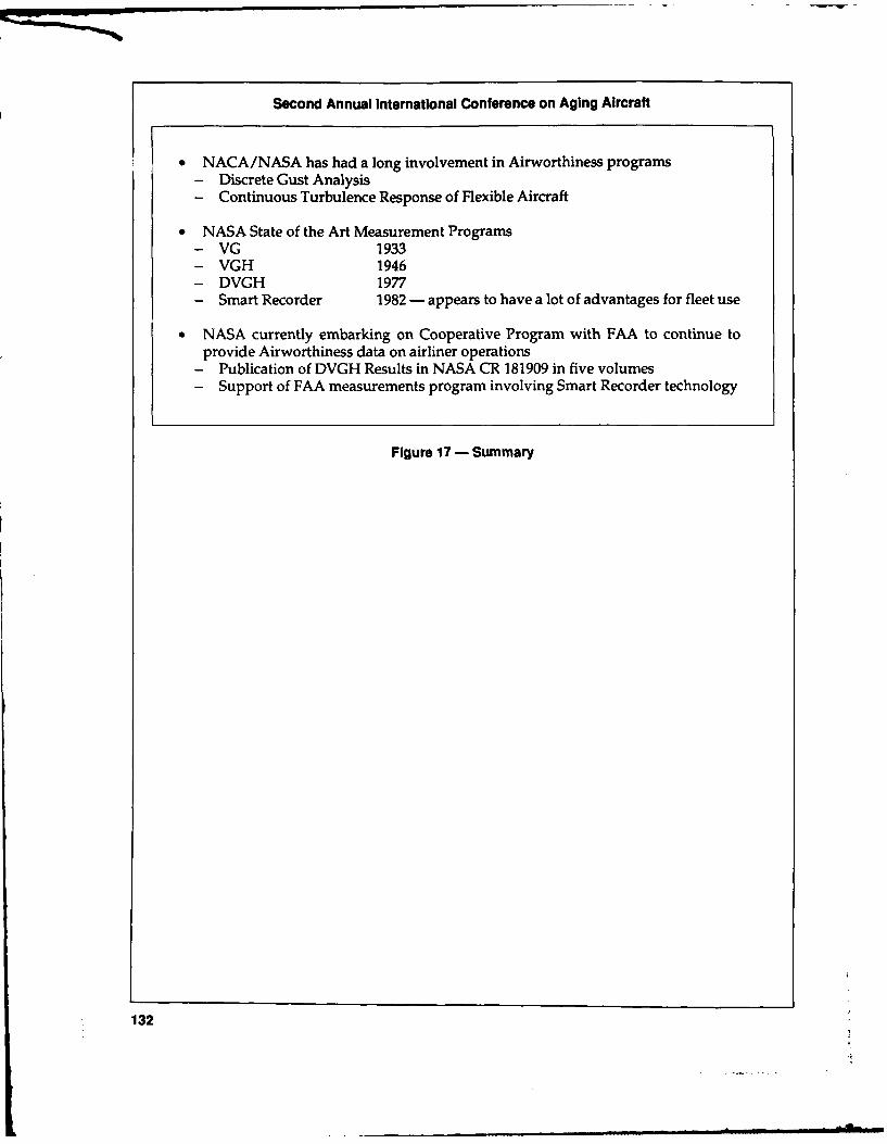
Second Annual International Conference on Aging Aircraft
* NACA/NASA has had a long involvement in Airworthiness programs- Discrete Gust Analysis- Continuous Turbulence Response of Flexible Aircraft
* NASA State of the Art Measurement Programs- VG 1933- VGH 1946- DVGH 1977- Smart Recorder 1982 - appears to have a lot of advantages for fleet use
* NASA currently embarking on Cooperative Program with FAA to continue toprovide Airworthiness data on airliner operations
- Publication of DVGH Results in NASA CR 181909 in five volumes- Support of FAA measurements program involving Smart Recorder technology
Figure 17 - Summary
132

Flight Loads
J. BEN DE JONGE
Netherlands National Aerospace Laboratory (NLR)
Ladies and gentlemen, it's my pleasure to The second is gathering of gust statistics.give you a review of program on the acquisi- Acceleration data were converted to derivetion and usage of loads data for the KSSU-747 gust velocities, and that is comparable to theaircraft from the Aircraft Condition Monitor- VGH programs.ing System (ACMS) recordings. KSSU stands That part of the objective is outside thefor KLM, Swiss Air, SAS Scandinavian, and scope of my present presentation. I will notUTA, the French airline, give you information about that part. How-
This program has been active from 1974 ever, the total data base at this moment in-until 1989 and we at NLR acquired this data cludes nearly 122,000 flight hours and andunder contract with KLM Dutch Airlines with more than 24,000 flights. That is considerablythe moral support, I would say, of the Dutch more than the NASA VGH data base on thatCivil Airworthiness Authorities, who also paid subject.for part of the data analysis programs. In this program we had a number of limita-
In mybrief review I will give you a shortde- tions. In the first place, we were only allowed toscription of the data acquisition procedures - make use of the existing ACMS that was onthe type of data acquired. I will give a brief board the aircraft. No changes to this systemreview of the total data base that is now avail- were allowed. No impairment of the aircraftable, but I will concentrate on an example of the operation was allowed. It was also a require-application of the data that were acquired in ment that the cost should be kept down to athis program. bare minimum. The total cost for KLM has
The program objectives were twofold. The never been more than $25,000 a year in thisfirst is the monitoring of aircraft usage and load project.experience in relation to fatigue for these air- The data acquisition procedure is as showncraft involved. This information is operator- in Figure 1. You have to keep in mind that theseoriented. 747 aircraft have been equipped with ACMS
133

Second Annual International Conference on Aging Aircraft
associated with the maintenance of the aircraft.
Data Acquisition Procedure But in this case they were run through a specificprogram that was called the AIDS fatigue data
* KSSU Boeing 747 aircraft have been program, and a limited number of the recorded
equipped with ACMS recorders data that were relevant for describing the air-craft usage and relevant to the load experience
" A large number of parameters are were extracted from this general batch of ACMScontinuously scanned and are re- data and stored in the ACMS fatigue data base.
In this data base all the data are stored on aflight-by-flight basis. There are three types of
* A limited number of data, relevant data. The first is general data describing the
for describing usage and load expe- type of flight, the date of the flight, takeoff date,
rience, are extracted from ACMS data the departure airport, destination airport, and
tape and stored in; things like that. The second is flight profiledata. Every flight is split up in a number of
ACMS Fatigue Data Base segments. For example, when the altitudechanges 2,000 feet, you start a new segment.
Data are stored on a flight-by-flight basis During cruise, a new segment is started everyhour. At the end of each flight segment the
Stored data include: speed, altitude, the aircraft weight, were re-corded. So, from this flight profile data you
* General flight data, such as type of have a picture of the mission profile. The thirdflight, date, tow, departure and des- is CG acceleration data. The peaks and troughstination airport values were scanned and stored in the data
base together with the instantaneous time of* Flight profile data, such asspeed,al- occurrence. Having the mission profile data,
titude, A/C weight and cabin pres- the change of the weight, speed and things likesure during flight that, you can then derive gust velocities. You
can reduce acceleration data to gust velocities.* C.G. acceleration data But, as I said, that is outside the scope of this
Values of recorded acceleration presentation.peaks/troughs with time of occur- Figure 2 gives a brief review of the type ofrence standard output that was produced as an over-
all summary of all flights. There are about24,000 flights. It is distributed by flight dura-tion intervals with a concentration in the area ofseven to eight hours, that's the trans Atlanticflight time of the 747. The general review in-
recorders. In these recording systems a large cludes the average flight duration, averagenumber of parameters - and I mean a few block time, and average takeoff rate.hundred parameters - are continuously The other type of information is usage sta-scanned and they are recorded if specific crite- tistics for various altitude bands. Figure 3 showsria are met. For example, in periods of severe the altitude band of 10,000 to 15,000 feet. Youturbulence, during takeoff, landing, and now see the average time spent in that flight inter-and then at intervals during the flight. val, the speed within that interval.
That's the standard equipment in these Figure4shows the35,000 feet to40,000 feetaircraft. The recorder data are put on a mag- interval that is, on the average, the cruise alti-netic tape. The magnetic tape is brought to the tude for the longer flights.computer facility of the airline and all the data Figure 5 is an overall summary of the re-are subjected to analysis for purposes largely corded CG accelerations according to altitude
134

J. Ben do Jonge
FLIGHT FLIGHT DURATION INTERVAL. 1I1RSI ALLT YPE FLIGHTL GEND .0- .5 .5- 1 1-1.5 1.5- 2 2 - 3 3 - 4 4 - 5 5 - 6 4 - 7 7 - 1 t - 9 9 -II 010 DUA TI ONS
NUMBER Or A 1591 1739 1110 1577 1347 1607 765 1651 4849 4696 1936 490 399 21757
PLIGHTS Of B 9 43 24 55 90 41 24 4 17 15 22 I0 0 362
INDICATED C 0 1 2 0 0 0 0 0 0 0 0 0 0 3
FLIGHT TYP9 0 1 4 3 10 7 10 0 a 1 0 0 0 0 36
0 23 37 1 11 22 16 4 4 39 24 17 5 0 200
ALL 1624 1624 5149 1453 1440 5668 765 159 4906 4735 175 S05 399 24356
AV•RA ELIGHT .44 .76 1.26 1.72 2.57 3.47 4.51 5.56 6.52 7.52 8.37 9.54 10.56 5.01
DURATION IHRS
AVERAGE BLOC% .16 1.14 1.61 2.15 3.05 3.95 5.04 6.02 1.04 0.05 9.14 9.96 10.94 5.41
TIME (10S6
AVERAGE TO 222.60 225.36 2)3.51 230.34 250.70 267.20 284.44 293,53 302.24 318.94 324.42 339.53 347.64 263.12
1X 1000 GJ
STAD. DEV. 13.9 21.49 24.97 20.22 20.27 24.50 21.60 19.16 15.95 1.71 17.05 17.70 14.04 43.13
TO (X 1000 OGI
AVERAGE FUEL 6.43 9.92 15.06 19.64 26.33 36.52 51.62 62.70 74.37 07.02 97.07 111.19 124.27 57.76
COSUPTIOW IN 1000 0GI
STAND. IV. FUEL 4.64 5.83 6.60 5.18 5.05 5.49 7.44 5.58 6.10 6.09 6.66 7.77 7.14 33.90
COOSUOPTION IX 1000 KG
Figure 2 - Summary Review of Recorded Flights
-------------------------------- U s A G E - S T A T 1 S T I C 9 PESULTS. FLIGHT PROFILE DATA
,,,,,,,nto,,,,,,,,,,,o *t #4A* ALTITUDE INTERVAL 10000 - 1500o FEET ****.....*.*..**...*04 o,,,,,,,,nn,,,0,,,,,,* *******
AVERAGE FLIGHT DURATION INTERVALS (0RSI ALLVALUES WITHIN FLIGHTALTITUDE SEGMENT .0- .S .5- 1 1-1.5 1.5- 2 2 - 3 3 - 4 4 - 5 5 - 6 6 - 7 7 - I 6 - 9 9 -10 010 DURATIONS
T1 SPEIUT [I .146 .101 .019 .100 .099 .099 .107 .102 .104 .110 .131 .125 .11 .11
0EIGHT I 1000 GI 216.37 220.41 221.14 220.54 214.41 247.69 256.4 262.3 2367.06 213.44 21.55 260.37 296.66 251.51
VELOCITY I6/OECI 189.34 10.26 176.62 168.46 174.06 170.62 162.44 164.44 112.23 161.21 177.25 101.59 116.93 160.10
MACH N06A .56 .55 .53 .51 .53 .54 .55 .504 .56 .55 .54 .55 .57 .5
ALTITOD8 IS 1000 Fti 12.94 12.60 12.43 12.31 12.47 12.43 12.42 12.43 12.42 12.43 12.44 12.42 12.40 12.49
#. ........ -4 .... ALTITUDE INTERVAL 15000 - 20000 FEET f- ....*.0* .04,H00,,,,,H,..t,,,,,,,.,0,0,,,,,,,.,,00,H
AVERAE FLIGHT DURATION IOTZPVALS I6S! ALLVALUBI WITHIN FL IGHTALTITUDE SEGMOE .0- .$ .5- 5 1-0.3 1.5- 2 2 - 3 3 - 4 4 - $ 5 - 6 G - 7 7 - 6 6 - 1 9 -10 >10 DURATIONS
TIM l1MIll (11831 .094 .010 .083 .062 .003 .093 .103 .09 .099 .116 .132 .117 .110 .10
6IGI0I6 (X 100 61 230.90 221.74 227.5 221.70 336.05 349.509 260.50 264.49 264.31 270.38 274.32 207.16 207.21 21.99
V3LOCl1 IN/KBCI 203.61 202.00 200.94 10.67 200.39 200.46 207.35 206.01 204.91 206.73 203.33 207.76 212.14 205.21
MACH NUMBER .63 .43 .62 .61 .42 .63 .64 .64 .44 .64 .63 .64 .64 .64
AL17UDIE II 1000 FTI 14.03 17.44 17.03 17.01 I.0 17.52 17.54 11.54 17.55 17.56 17.S6 17.54 17.SS 17.51
Figure 3- Example of Flight Profile Data
135

Second Annual International Conference on Aging Aircraft
--------- G - -T T I C S REULTS FLIGHT PFO... . . .............................
*U*U**,** * U***UU3*0 4*S ALTITID INTERlVAL 30000 - 35000 FEET 4**U*4*t*****OUU*0*******14**** ****C**************
AVERAG8 FLIGHT DOURATION INTKRVALE (11RS ALLVALUES WITHIN FLIGHTALTITUO SEGMIENT .0- . .3- 1 1-1.3 1.5- 2 2 - 3 3 - 4 4 - 5 3 - 6 6 - 7 7 - I I - 9 9 -10 >10 DONATIONS
TIME SPENT InoSI .002 .003 .292 .304 .029 1.034 1.007 2.077 2.004 3.021 4.402 4.055 5.289 2.20
WEIGHT IN 1000 E01 20.71 213.31 226.37 221.00 241.54 259.54 20.09 26.50 269.$1 279.59 261.67 200.65 269.09 214.63
VELOCITY 1N/SWI0 258.61 246.28 246.55 246.16 249.60 252.01 253.27 252.11 251.15 231.04 251.10 251.00 2S1.06 251.39
NACH NUBER .04 .62 .11 .02 .62 .83 .03 .13 .64 .64 .14 .84 .04 .14
ALTITOE ( 1000 OFT 22.79 22.17 J2.81 33.07 31.00 33.35 33.00 33.22 21.23 33.15 32.96 33.04 32.99 33.12
#+*,,, * .... #* ... t.0U4 ALTITUDE INTERVAL 33000 - 40000 FEET ...... I ........,,,*,U,*,,0,,,,,,A,,
AVERAGE FLIGHT DOJATIO6 INTERVALS (MIRSI ALL
VALUES WITHIN FLIGHTALTITUDE SEGMENT .0- .5 .3- 1 1-1.0 1.3- 2 2 - 3 3 - 4 4 - N 0 - . 0 - I - 0 - 9 9 -10 >0 DURATIONS
TIME SPORT 260SI .001 .009 .249 .628 1.106 1.549 1.561 2.420 2.113 2.504 2.62S 2.35 3.591 1.03
WEIGHT ( 1000 KG 236.04 216.12 216.10 215.06 231.11 234.14 244.19 246.65 249.16 251.01 20.90 251.40 241.09 247.22
VELOCITY 1I0S3C 251.30 246.00 247.99 240.31 249.14 250.00 250.11 250.53 249.01 250.53 249.91 250.64 250.20 250.10
MACN IMBER .5 .04 .1 .91 .#3 .04 .04 .84 .64 .04 .14 .04 .84 .84
ALTITUDE IN 1000 FTi MO.9N 35.05 36.11 31.12 31.15 11.14 36.53 36.62 36.46 30.29 36.20 36.56 36.65 36.51
Figure 4 - Example of Flight Profile Data
TOTAL TOTAL NUMBER OF PEAK OCCURRENCES IN INDICATED OLLTA-G. INTERVALSALTITUDE DISTANCE TIME U P W A R DINTERVAL FLONN SPENT
IFi I UNK] 1119S .15-20 .20-.25 .25-.30 .30-.40 .40-.50 .50-.60 .60-.75 .75-.90 .90-1.10 >1.10
1 3500 107652 1220.20 19072 x 6225 1329 717 60 21 3 1 41500- 3000 257511 167.30 14 00 9 1332 1412 612 00 6 6 53000- 5000 253521 1514.52 13164 6 4400 191 051 02 12 1 25000- 10000 870411 31S6.67 11361 x 436 1703 936 173 30 10 5 2
10000- 15000 05602 2722.50 4006 : 1963 015 429 113 32 16 415000- 20000 949962 231.51 2010 , 061 310 231 53 17 13 3 120000- 2500 1205227 2052.00 1639 X 700 206 154 54 21 6 325000- 30000 3029993 793,2 2947 x 1233 441 293 59 22 10 1 230000- 35000 26190429 53613.05 12215 K 4717 1611 974 170 50 26 2 2 535000- 40000 21687962 44611.17 9003 x 3666 1327 210 140 47 10 1 2
> 40000 141655 293.45 125 X 49 24 10 2ALL ALTITUDES 56140235 121094.30 00450 . 3405 11664 5767 1024 274 111 20 3 22
TOTAL TOTAL NU4E9 O PEAK OCCURRNCES SN INDICATED OELTA-G. INTERVALSALTITUDE DISTANCE TIME 0 0 W N W A N 0INTERVAL FLOWN SPENT(T! IM4) 1119S| .15-.20 .20-.25 .25-.30 .30-.40 .40-50 .50-.60 .60-.75 .15-.90 .90-1.10 >1.10
< 100 297652 1221.20 0942 X 1819 399 185 21 10 7 11500- 3000 251594 1367.30 71070 : 170 436 124 30 25 13 11 13000- 5000 352521 1574.52 5716 1009 517 202 20 15 3 4
000- 10000 870411 2110.01 0715 x 2473 911 491 94 20 a 3 120000- 13000 954820 2722.50 3310 x 1232 449 310 77 29 12 315000- 20000 949902 231.01 1011 641 205 154 33 9 A 3 120000- 25000 1290221 2052.00 1470 o 401 300 116 17 9 221000- 20000 302993 7993.32 2000 o 93 273 220 56 19 4 1 130000- 35000 26199429 53613.0 11217 X 309 1454 735 159 51 25 235000- 40000 21608762 44611.17 0214 x 2901 1034 594 120 43 12 5
, 40000 141655 293.45 111 * 37 14 12 1ALL ALTITUDES 5614123 121094.30 50162 K 17993 6022 3155 644 231 96 25 4
a STATISTICALLY URR3LSAIZL DATA DUE TO A FLOATING LIMIT SETTIN Or 0.16 G
Figure 5 - Recorded C.G. Acceleration Peaks
136

J. Ben do Jonge
interval and number of peaks within the vari- Air and KLM - and for KLM there is a combi-ous intervals. nation version and a full passenger version -
The application of the usage data is, in the average flight duration is in the order of fivefirst place, to compare the design usage with hours.the actual surface experience of the aircraft for The first observation, is that this flighta particular operator with regard to, let's say, duration is considerably longer than the designthe mission profile assumptions, flight length assumption of three hours. But looking then todistribution weights and cabin pressure differ- the flight length distributions for Swiss Airentials. (See Figure 6) compared to the KLM, you'll notice that for
You may also study the variation of usage Swiss Air there is a pronounced peak at thewith time for a particular operator. The changes very short duration flight lengths.in the network of an operator, for example, The reason for this is that Switzerland is amay result in changes of its operation and small country and there are two airports, Zu-changes of its load experience. rich and Geneva. They flew from Zurich to
That is, in the first place, the comparison of John F. Kennedy with an intermediate stop, athe design usage and, in the second place, you half-hour flight, at Geneva. That was a verymay compare the design loads with service short duration flight and it had a very pro-experience, and finally get some idea about the nounced influence on the average flight duration.conservatism of the design data with regard to Figure 9 looks at the average cabin pres-turbulence that is currently used. sures that were reached. The first observation
Figure 7 for the 747, gives a review of the is that in all KLM and Swiss Air flights the cabindesign mission mixture for the aircraft. This is pressure remained well below the design valuea specific mission mixture, with a concentra- of 9 psi. There is a concentration at the 8.7 to 8.8tion for the seven-hour transatlantic type of psi. That's a considerable difference in terms offlight. The average mission mixture resulted in fatigue from the 9 psi design value.an average flight duration, design flight dura- But for Swiss Air that is because of that verytion, of three hours. You may recall that the short flight from Geneva to Zurich. In 30 per-design life of the aircraft was 20,000 flights or cent of the flights the cabin pressure remained60,000 flight hours. These figures then match. below 8.2 psi. You can imagine that this has a
Figure 8 shows the observed flight dura- considerableeffectonthefatiguelifeconsump-tion distribution from our data base. The Swiss tion -- if you assume a pressure of 9 psi for
every flight and in actual fact, in 30 percent ofyour flight cycles the pressure remains below8.2, you have a considerable saving in fatiguelife consumption. This is the type of informa-
• Comparison of design usage with tion that is very useful for an aircraft operatorservice experience and also for the airworthiness authority.
- Flight length distributions Figure 10 looks at the mission profiles, the- Weights usage. The other subject, of course, is compar-- Cabin pressure differentials ing the design loads with actual measured- Variation of usage with time loads. Shown here is the CG acceleration spec-
* Comparison of design loads with serv- tra, thedotted curve is the measured curve,andice experience the other curve is the flight condition spectra.
- Conservatism of design We calculated the loads spectra that youwould find for the actual mission profile if you
" Gust load data used the NACA TN4332 data that were usedfor the 747 in calculating the design loads spec-tra. You see here that the TN4332 data areconservative compared to what is actually
Figure 6 - Examples of Application measured. That is a comforting feeling for the
137

Second Annual International Conference on Aging Aircraft
DESIGN MISSION MIXTURE FOR THE BOEING 747
38000 ft34000 ft
10000 ft..
If1 hr FLIGHT e 3 hr FLIGHT
(100 KIP PAYLOAD) (100 KIP PAYLOAD)
38000 ft34 000 f t
10000 ft1500 ft
so0 7 hr FLIGHT * 4 hr TRAINING FLIGHT
(100 KIP PAYLOAD) (0 PAYLOAD)
NOTE: IN 60,000 HOURS OF SERVICE OPERATION.THE FOLLOWING DISTRIBUTION OF FLIGHTSIS USED: 9 9600- ONE HOUR
* 4800 -THREE HOURS* 4800- SEVEN HOURS* 600- TRAINING
Figure 7 - Design Mission Mixture for the Boeing 747
airline and for the airworthiness authority and have the bank angle of the aircraft, you canin actual fact also for the passengers flying in calculate the associated maneuver load factorthese aircraft. with the bank angle. We measured the bank
We should keep in mind that we have angle and subtracted that from the total meas-measured here our data that include maneu- ured incremental acceleration and got the cor-vers and gusts. We were not able, because we rection. That way you have then subtracted thejust got acceleration peaks, to distinguish be- parts of the load factors due to the maneuver.tween maneuvers and gusts in the first in- In many cases, especially at low altitude, thestance. We were not able to apply a filter. We airplane is making turns, or is in a holdingjust received reduced data from the ACMS pattern, and you have a certain bank angle andsystem and we could not change them. you are meeting the turbulence. So, you have a
There is another conservatism in that. We situation that the turbulence loading is super-tried to correct our CG data for maneuvers by imposed on the long duration type of maneuver.subtracting a part of the load factor that we Looking at the results in Figure 11, youthought was due to a turning maneuver. If you have to consider that it is a logarithmic scale.
138

J. Ben de Jonge
This program shows that it is possible toobtain very relevant information at very little
FLIGHT DURATION DISTRIBUTIONS FOR cost and without very much difficulty.DIFFERENT 747 OPERATORS Very few airlines apply systematic usage or
SWISSAIR loads monitoring in their aircraft. KLM stopped(AVE.,, 5.10 ht)AV-. their activity just last year for the sake of saving
the $25,000 a year.The reason there is very little application so
far is that service loads monitoring only be-77 __comes effective if there is close cooperation and
agreement between the three parties involved.These three parties are the airline, the aircraftmanufacturer and the airworthiness authority.
The airlines say they know what they have1 _ _ ___ "/I-at the moment with regard to inspection and
E. to.71 hmaintenance burden. Those measurements canresult in two findings. Either our load experi-ence is more severe than expected, and then wewill get a more severe maintenance burden. Or,on the other hand, if it turns out that our loadexperience is less severe, we are not sure thatwe get the benefit for that. Will the authorities
KL. FULL PAX(AVE hr) really allow a reduction of the maintenance
burden?The airworthiness authorities are very re-
luctant to say beforehand that they are willing0 7 8 9 1 >10 to give a reduction. One of the reasons is that
FLIGHT LENGTH (hr) the civil airworthiness authorities are under-
staffed, people are very busy and they do notwish to commit themselves in this area.
Finally, you have the aircraft manufacturer.Figure 8 - Flight Duration Distributions The aircraft manufacturer is interested in this
type of activity but not really enthusiastic. Itturns out that they can do that but it would
This might be a relatively simple way of split- mean a lot of extra work.ting maneuver loads and gust loads. Although the means are there to apply
Figure 12 is just a picture of the variation in usage monitoring for operators at low cost,usage. You see three periods. The small tri- people don't do it or you find very low applica-angles on the right side are variations over the tion of systematic monitoring. We continue toperiods of the average flight time for the KLM apply relatively large safety factors or scatterCombination. Perhaps not very drastic here, factors to cover the uncertainty, the actualbut the average flight duration changed in the uncertainty, about our service loads experi-period of two years for this aircraft from nearly ence.six hours to a little bit more than five hours, just Monitoring usage and loads experiencebecause of a change in the network, an opera- offers the possibility to take away a certaintional change, or perhaps the introduction of amount of uncertainty in our fatigue assess-another aircraft in the fleet. These variations ment.Takingawayapartofuncertaintymeansmay be important, and it is interesting for the an inLrease in the overall accuracy and in theairline to be aware of such changes. overall safety of aviation.
139

Second Annual international Conference on Aging Aircraft
PRESSUREDIFFERENTIAL PERCENTAGE OF FLIGHTS
(PSI) 10 20 30 40 so
>8.
rDESIGN VALUE I Ml
Fiur -DitibtonofMxiumCbi resueDifeetilfo To74 Oeatr
CO8ARSO OFP-ICE8NDRCRDD8g
ACEERTONSECR8FR.OIG74
LOAD ~ ~~ --- FATRAERGWISINPOILEAI
PAKCERTEEN MPECAN CONTING METHO
Figure 10- Airframe Stutua IDrS FTGPROGRAM
140.

J. Ben do Jonge
LOAD FACTOR SPECTRA FOR BOEING 747 BELOW 10000 ft,WITH AND WITHOUT "BANK ANGLE CORRECTION" INLR ACMS DATA)
I &--- NOT CORRECTED FORO i TURNING MANOEUVRES i
1.0 0-43 CORRECTED FOR
LOAD FACTORINCREMENT
AINz 0.5_
0
-05-
-1.0 Anz
cor nz -- (col I
I O=BANK ANGLE LI.
-1.5~~~~~~~-j- 11iL IL LJ.JI UJ L1II10
-1 1 0 1 0 W 10 004
TOTAL EXCEEDINGS IN 3932 FLIGHTS
Figure 11 - Load Factor Spectra for Boeing 747 Below 10,000 ft,with and without "Bank Angle Correction" (NLR ACMS data)
PERIOD
82/83 - A,
80/81 -
% x"---x KLM FULL PAX
77/79 -' < 0 SWISSAIRKLM COMBI
I I45 6
AVERAGE FLIGHT TIME (HOURS)
Variation of average flight duration with timefor two 747 operators
Figure 12- Variation of Average Flight Duration with Time for Two 747 Operators
141
ima m i i /llmm - -- i n m I

The Responsibilities of FAA,the Manufacturers and the Airlines for
the Continuing Safety of Aging Aircraft
WILLIAM R. HENDRICKS
FAA Director of Accident Investigations
I'm very honored to present my paper to In these terms, I would place it in the samethis distinguished group and I realize that I'm category as the Eastern Flight 66 accident, whichin with the heavyweights of the industry and occurred at JFK in June of 1975, killing -113 pas-the top structural and maintenance experts in sengers and crew. This was a thunderstormthe world in the subject of aging aircraft. Your accident which precipitated the first full-scaleknowledge on this subject far exceeds mine. efforts by the FAA and the industry to develop
My perspective is from the window of acci- wind shear detection and training programs.dent investigation and I hope to focus on the I would also place it in the same category asAloha Airlines accident which occurred in the the PSA, the midair collision accident that oc-Hawaiian Islands on April 28th, 1988. I'd like to curred in San Diego in September of 1978. Thisshow the factors that were developed during accident killed 144 people and it resulted inthat investigation and how they spotlighted massive changes to the National Air Spacethe issues concerned with aging aircraft. System. TCAs and other major airspace changes
While the Aloha accident wouldn't be clas- have evolved from that accident.sified as a catastrophic event in terms of the The Aloha accident, which involves an in-classic high fatality major aircraft accident, I flight structural failure to a high-time airplane,believe that it will be looked on as a landmark may well be remembered as the springboardaccident in terms of the intense industry inter- for higher standards in new technology andest and expedited efforts for corrective aclions procedures for maintaining the world's agingthat have evolved, aircraft.
142

William R. Hendricks
Activity associated with the Aloha accident decelera ted below 170 knots, the airplane againby no means overshadows the long-term ef- became less controllable. The captain elected toforts both by the FA A and industry with regard maintain the speed at 170 knots throughout theto aging aircraft. There has been considerable landing approach.progress made over the years resulting in At that time it was also noticed that thecomprehensive programs to monitor and re- plane had lost power on the number one engine.pair transport airplanes throughout their op- The flight landed on runway 2 at the Kahuluierational life. The Aloha accident has served to Airport at 1358 hours. A normal touchdownaccelerate and to magnify these efforts. and landing was accomplished using the brakes
I would like to first look at the in-service and reverse thrust on the number 2 engine.structural history of the Boeing 737 and the The entire episode from the time of theinterrelationships between the FAA, the manu- structural failure at flight level 240 to touch-facturer, and the operator as they pertain to the down was approximately 11 minutes. Therecausal factors involved in the accident. I will were 95 persons on board; 89 passengers, twothen briefly discuss some of the specific activi- flight crew, three flight attendants and an FAAties and recommendations for corrective action air traffic controller in the jumpseat.that have been initiated since this occurrence. The senior flight attendant in the first-class
I think it might be a good idea to review first cabin was lost during the decompression; 59the accident scenario. As I mentioned before, passengers were taken to the hospital withthe accident occurred on April 28, 1988. Aloha injuries from minor to serious.Airlines Flight 243, a Boeing 737-200, was on a I think, all factors considered, it was aregularly scheduled passenger flight from the miraculous escape for those on board exceptIsland of Hilo to Honolulu, Hawaii. for the tragic loss of the flight attendant. In-
Shortly after leveling the airplane at flight deed, the flight is a testimony to the skill of thelevel 240, with the first officer at the controls, flight crew and to the residual strength of thethe crew heard a loud clap and a whooshing Boeing 737.sound behind them, followed by the sound of If you recall, the fuselage structure fromrushing air. They observed almost immedi- above the floorlevel on the left side to about theately that the cockpit door was gone and that top of the window belt on the right side andthere was blue sky where the ceiling of the extending from just aft of the passenger entryairplane had been in the first-cla-s section. door to just forward of the wing were missing
The captain immediately took control of completely, from body station 360 throughthe airplane and began a 4,000 foot per minute fuselage station 540. All fractures associatedemergency descent using speed brakes and with that break-away were typical of overload,maintaining an air speed of about 280 to 290 static overload separations.knots during the initial portion of the descent. The NTSB in their report determined thatAir traffic control was advised of the emer- the failure initiated along the number 10 stringergency and approved a diversion to Maui. on the left side near fuselage station 440. The
The captain stated that during this time top skin ripped from that point down and tothey were experiencing sev.wre vibrations and the left on the left side and up and over thethe airplane was handling very rough. He slowed airplane and rearward on the right side. Morethe airplane to about 200 knots as the flight like an egg shell breaking apart. The floor ondescended through 10,000 feet. The flaps were the left side in the area of fuselage station 440set to five degrees. Then the crew tried to was the most severely deformed. The oxygenextend the flaps to 15 degrees, the airplane system lines were torn out below the decks andbecame less controllable so the crew returned there was no oxygen available.the flaps to the five degree position. There were about four or five floor beams
The captain then attempted to slow the broken through, primarily on the left side of theaircraft in preparation for the landing, but as it airplane where the most severe damage oc-
143

Second Annual International Conference on Aging Aircraft
cured in the area of fuselage station 440 - that the service history of the 737, the manufacturerwas in the area where the NTSB surmised that issued several service bulletins pertaining tothe peak loads occurred. disbonding corrosion and fatigue cracking
After the accident a witness was located - around the fuselage lap joint.a passenger actually - who boarded the air- The fuselage is divided into sections, withplane at its origination point. The lady was sections 41, 43 and 46 comprising the majorityabout four-foot ten inches tall and as she was of the pressure vessel. (See Figure 1) Thesegetting on the airplane, she noticed a crack in sections, along with section 48, are butt joinedthe fuselage at about her eye level. She de- together at circumferential frames to form thescribed it in later conversations as about a six- entire fuselage. Section 43 forms the forwardinch crack with the skin actually protruding cabin area, which was the area of the missingfrom beyond the rivet heads. The area she upper section.describes was along the 10-L stringer in the The sections are constructed of circumfer-area that the NTSB figures that the separation ential frames and longitudinal stringers thatoccurred. are covered by formed skins which are rivetted
This was a high-time, high-use airplane to the underlying structure of the stringers.and it was manufactured in 1969. At the time of (See Figure 2)the accident, it had accumulated 45,493 flight Each skin panel in the upper lobe of sectionhours. More significantly, it had 89,090 cycles, 43 is the length of the entire section, which is 18which equates to about 13 flights a day for 19 feet long. I think it is interesting how theseyears. This was the second highest number of panels are constructed. Two sheets of .036 inchflight cycles in the worldwide 737 fleet. aluminum are hot-bonded together. The tear
A sister ship, also owned by Aloha Air- straps are formed by an acid milling processlines, had accumulated over 90,000 cycles, which which takes away one of the layers of skin inwas the highest for any 737 at the time. That the prepared places, and leaves a waffle-likeaircraft was in the Aloha hangar for mainte- appearance with the tear straps spaced aboutnance at the time of the accident. ten inches apart. The panels are joined longitu-
As I mentioned before, this accident has dinally by overlapping the edges of the indi-spawned many questions concerning aging vidual panels and fastening them with rivetsaircraft, not only the 737, but all categories of and a bonding process. One row of rivets se-the so-called senior aircraft fleet. It has also cures the lap joint to the underlying stringerfocused attention on the individual responsi- which in turn is attached to the frames bybilities of the FAA, the manufacturer and the riveted clips.airlines in maintaining the safety and integrity Through aircraft line number 291, singleof the system. thickness sheets at the lap joints are joined
By that I mean the manufacturer's respon- together with a cold bonding process. The three-sibility in the design, production and tracking inch overlap or lap joint area was single thick-of their aircraft, the FAA in their role of certifi- ness sheets for the two panels being joined. Thecation and surveillance, and the operator's single thickness areas for the lap joint were alsoresponsibilities in their compliance with the formed by the acid etch process. (See Figure 3)prescribed and approved maintenance practices. The cold-bonding process used an epoxy-
These responsibilities, when properly impregnated glass cloth, which was about theapplied, should overlap and tie together to width of the joint, to join together these longi-form a buffer or a margin of safety to preclude tudinal edges of the skin panels. Then, thean accident like this. These joint responsibili- bonded joint was fastened together with threeties form the premise on which safety of our longitudinal rows of countersunk rivets, thesystem is based. middle row of which attached the skin to the
Notwithstanding the facts of this accident, stringer. This formed the lap joint. This bond-it's my contention that the system almost worked this cold bond - cured at room temperatureand I say it for these reasons. Very early on in after assembly.
144

William R. Hendricks
as
S4, 907
0 '
5S14
8S S:20259.5
1S79
SEE DCTA L. I
Figure 1 - Lap Joint Inspection(See Figure 2 for Detail 1; Figure 3 for Detail 2)
After aircraft number 291, Boeing discon- locations of the fuselage lap joints. An inspec-tinued the cold-bonding process and used a tion and repair procedure was included in thesmooth close-fitting surface-sealed lap joint service bulletin.with increased joint thickness. The overlap- Following the third revision of the serviceping piece of skin was retained at the double bulletin by Boeing, and in view of confirmingthickness and attached to a single thickness reports of multiple site fatigue cracking alongunderneath. This redesigned joint became upper row fasteners, the FAA acted by issuingnecessary as problems of delamination of the an airworthiness directive in October 1987,cold-bonded joint were encountered. which required a visual inspection of the fas-
The first service bulletin which concerned teners along the number 4 stringer - 4 leftthe lap joint delamination corrosion repair was and right - from fuselage station 360 to 1016issued in 1972. Boeing revised this service bulletin on all 737s with 30,000 or more cycles.three times, elevating it to alert status with the It specified that any cracks detected wouldthird revision on August 20, 1987. This up- have to be repaired in accordance with thegraded state followed several reports from instructions contained therein and it also speci-operators of fatigue cracking along the fastener fied that if any cracks were found on the visual
145

Second Annual International Conference on Aging Aircraft
FP FA MESTATI ON
D OUBLER
LA ~ k" 4UPPERALUPE
TARA STRAP'k OWO PSEN~
CONLDCTONDA(NSE FIR3
SKIN
(DISSONDETAI SE EALI
TYPICAL SKIN LAP JOINT
Figure 2 - Lap Joint Inspection (Detail 1, Typical Skin Lap Joint)
146

William R. Hendricks
2 TYPICAL FATIGUECRACK LOCATION
CRITICAL UPPER OUTER OR
ROW OF FAS'tENERS UPPER SKIN
0o 0 Q © 0 Q
UP 0© ( 0 (D 0 Q
~STRIZNGER
INNER ORLOWER SKIN
Figure 3 - Lap Joint Inspection (Detail 2)
inspection, an eddy current inspection would of detectible multi-site cracking were foundbe required along the entire length of that along the number 4 stringer as well as in manystringer, other areas along the fuselage lap joints.
In accordance with the requirements of the In the fall of 1987, prior to the FAA's issu-AD issued by the FAA in November 1- 7, ance of the AD, the manufacturer, as part of itsAloha inspected its entire 737 fleet, and on the aging fleet research program, had sent a teamvisual examination of the accident airplane at of engineers to Aloha to collect data and to lookleast two areas of corrosion were found along at some of these high-time 737s. Although thisthe number 4 stringer. These areas were prop- accident airpiane was one of the four Alohaerly repaired and,according to Aloha, the eddy 737s with over 65,000 cycles, it was not one ofcurrent inspection along the entire stringer, as the airplanes examined during this visit.required by the AD, was also performed. Ac- In the general discussions with Aloha fol-cording to the maintenance records, no other lowing the team inspection, and in its reportdefects were found. delivered to the operator on April 14, 1988,
However, after the accident the airplane which was two weeks before the accident, thewas inspected by NTSB and many other areas Boeing team did express concern about the
147

Second Annual International Conference on Aging Aircraft
condition of the higher-time airplanes as well have been to discover cracks? The Board saidas about the adequacy of the maintenance notoallthesequestions.Apropereddycurrentprogram to cope with the existing corrosion inspection should have detected those cracksproblems in the corrosive environment that that were found along the number 4 lap jointAloha operates in. after the accident. They indicated that either an
So, in theory the system was working. All eddy current inspection was not conducted or,of the responsible parties were attuned to the if it was, it was ineffective.lap joint problem and had in fact taken some Was the FAA's surveillance of Aloha's main-form of action to correct this deficiency. These tenance program adequate? The Board said no,actions were not sufficient and in this case the the FAA failed to evaluate properly the Alohasystem failed and an accident occurred. maintenance program and to assure that the
The obvious questions are how and why airline's inspection and quality control defi-the system broke down and what are we doing ciencies were corrected.about it. Congressman Oberstar said it best at As I said before, this accident precipitated athe June 1988 aging aircraft conference. He said lot of questions. Many of them were raised atthen that what concerns us all is not that there the last conference and are still under consid-isn't a tracking system for aging aircraft. There eration here today.is. It's not that the system wasn't used because Do the current certification criteria and main-it was. What concerns us is that most of the tenance practices adequately account for theright steps were taken but the system still present use of high-time, high-cycle airplanes?failed. Is aviation technology adequate to detect
Boeing should have issued a service bulle- early signs of impending failures of aircrafttin to inspect cracks along the number 4 and 10 structure or do we need more advanced detec-stringers, and they did. The FAA should have tion technology?issued an AD requiring an inspection of the Are the corrosion control techniques usedstringer on number 4 lap joints, and they did today adequate for high-time airplanes?about six months before the accident. Aloha Are the human factors and realities of re-should have acted on these warnings, and they petitive, visual and NDI inspections properlydid, but they didn't find the problem. accounted for in the design and expectations of
A number of other people, including Con- inspections programs?gressman Oberstar and NTSB members, also Istherea limit to thelifespan of anairplane?asked these questions. Were the service bulle- And, if so, shouldn't it be taken out of servicetins issued by Boeing explicit enough or early before it reaches that threshold?enough. The Board said no, that Boeing should I know that a good many actions havehave issued an alert service bulletin in 1984 already been completed and many more areafter the first evidence of cracking along these actively underway as a result of your efforts.stringers were found. The regular service bul- With regard to the Boeing 737, as you know, theletin was issued and upgraded to alert status in FAA last year issued an AD that required the1987. replacement of all upper row rivets for aircraft
Was the airworthiness directive issued by 291 and below, depending on the number ofthe FAA as complete, comprehensive or timely cycles. That equates to about 7,200 rivets peras it should have been? The Board said no, the airplane and about $800,000 in expenses. So,FAA should have mandated the inspection of it's a big job.all lap joints instead of limiting inspections to Also, the FAA issued some NPRMs, one ofthe number 4 lap joints, which is applicable to the 737, which will re-
Were Aloha's inspection personnel suffi- quire mandatory structural modifications tociently trained for the task? Were they skilled those aircraft when they reach their economicaland experienced enough to recognize the prob- design goal. As I understand the meaning oflem when they encountered it? Was the inspec- that, it's the point in service where the mainte-tion as vigorous and meticulous as it should nance costs necessary to assure continued
148

William R. Hendricks
operational safety of an airplane would be this is an isolated exception to the provenexpected to increase significantly due to age- record of safety by all of our transport aircraft.related factors. Perhaps differently interpreted, I base this conclusion on the thousands of airit is the point where it becomes economically carrier hours that are successfully flown eachunfeasible to operate these airplanes. day all over the world.
For the Boeing 737 that goal was set for All one has to do is go to one of the major75,000 cycles or 20 years. Considering the origi- airports and look at the scope and the tempo ofnal cost of a 737 which was about $6 million, the operations and the complexity of the tech-and the cost of a new 737 today, which is at least nology involved to realize how extraordinarily$30 million, I would think that that economic safe our system is.design goal will be pushed out even further. The magnitude of this accomplishment is
The requirements of the new NPRMs rep- not only a tribute to the improved technology,resent a significant change in the philosophy but also to the constant attention to safety thatregarding the maintenance and safety of aging is deeply imbued in this industry and by theairplanes in that it sets a life limit on individual organizations that comprise our system.parts considered to be critical structure. This However, any failure, no matter how small ordiffers from the long-standing philosophy and insignificant, must be recognized and correctedpractice of repetitive inspections and appropri- before an accident occurs.ate repairs to assure safety throughout the Thus, while we did have a breakdown inlifetime of that airplane. the system in this case, we now have a tremen-
I think these actions are a positive step in dous effort underway to look at these deficienciesthe right direction and we all look forward to and make whatever corrections are necessary.more recommendations from the participants This, after all, is the purpose of this conference,of this conference which will address the con- to effect corrective action so that we don't havetinuing aging aircraft problems. another similar accident.
Although in the Aloha case, we did have an I think it's a great benefit to aviation to haveaccident, and indeed an example of how the the experts in this field meet together to resolvesystem didn't quite work, I would like to con- these most challenging issues, and we all lookclude on a positive note by saying that I believe forward to the results of your discussions.
149

Session III: Corrosion
CHAIRMAN JOHN J. DE LuCCIA
Manager, Aerospace Materials DivisionNaval Air Development Center
This is the second international conference how to protect airplanes and we do know howon the topic of aircraft aging, but since the first to treat corrosion. However, you have to realizeinternational conference did not have corro- that in order to maintain our airplanes, wesion as a speci 'c session, this will be the first expend a lot of manhours and we in the militarytime we're addressing this topic in regard to are not concerned with profit. We're concernedaircraft aging. with mission. Thus, for our F-14 airplanes it
Our laboratory is concerned about Naval takes, and we give, about 10 maintenanceaviation materials and specifically about their manhours per flight hour specifically devotedprotection. We have the most severe natural to corrosion. So, it takes a very labor-intensiveenvironment known to man, one in which we effort to make sure that those planes are prop-routinely fly our airplanes. erly maintained.
The fact is that some mechanical failures Figure 1 shows the triad relationship wehave their origin in corrosion and its electro- discussed before. How could we, the Navy, fitchemistry so we want to look at that aspect in into the triad?great detail. The FAA, asked us to share some of our
I also want to bring out now the fact that we products, procedures, techniques and knowl-have been flying some Navy airplanes - for edge with them with regard to corrosion. So,example, the A-3 - for upwards of 35 years. our little bubble at the upper right-hand por-Bear in mind that we fly in the world's worst tion of the triad is essentially us giving theenvironment and we have been able to do this information to the FAA.with the same airplane for 35 years. Before we go on to the formal topic, I again
You might say then, that the answers are all want to say a few words about the topic ofthere. Yes, the answers are there. We do know aging and corrosion. It's important to look at
IS0

John J. De Luccia
AGING AIRCRAFT PROGRAM _a_
CORROSION CONTROL & PREVENTION
Figure 1
that word "aging." The word aging, implies among them is corrosion fatigue and inter-time. We find that the phenomena of time has granular corrosion. Corrosion fatigue is a topicdifferent effects as you look at corrosion. of extreme importance and of extreme interest.
The left-hand portion of Figure 2 is the People very frequently talk about fatigue,time-dependent phenomena that we see on air- fatigue life, endurance limits and design loadsplanes. The corrosion that we see on airplanes and so forth and they're not taking into consid-that is time-dependent - general attack, pit- eration the environment. I was gratified to hearting, exfoliation, crevice corrosion and filiform Clyde Kizer make the statement that you throwcorrosion - all take time. What do they do? everything away when you have corrosionThey give us slow failure, with regard to fatigue because when you have
There are other phenomena that are time corrosion you don't have an endurance limit,independent. Those phenomena are, stress you don't have a design stress that you meas-corrosion cracking and environmental embrit- ured in the laboratory under dry conditions.tlement. These things happen without warn- Our speakers will talk about these topicsing. These are catastrophic. and hopefully we'll all go away smarter so that
In the middle of the figure we have time- we can preclude some catastrophic and long-related corrosion phenomena, and primary and short-term failures on our aircraft.
151.-
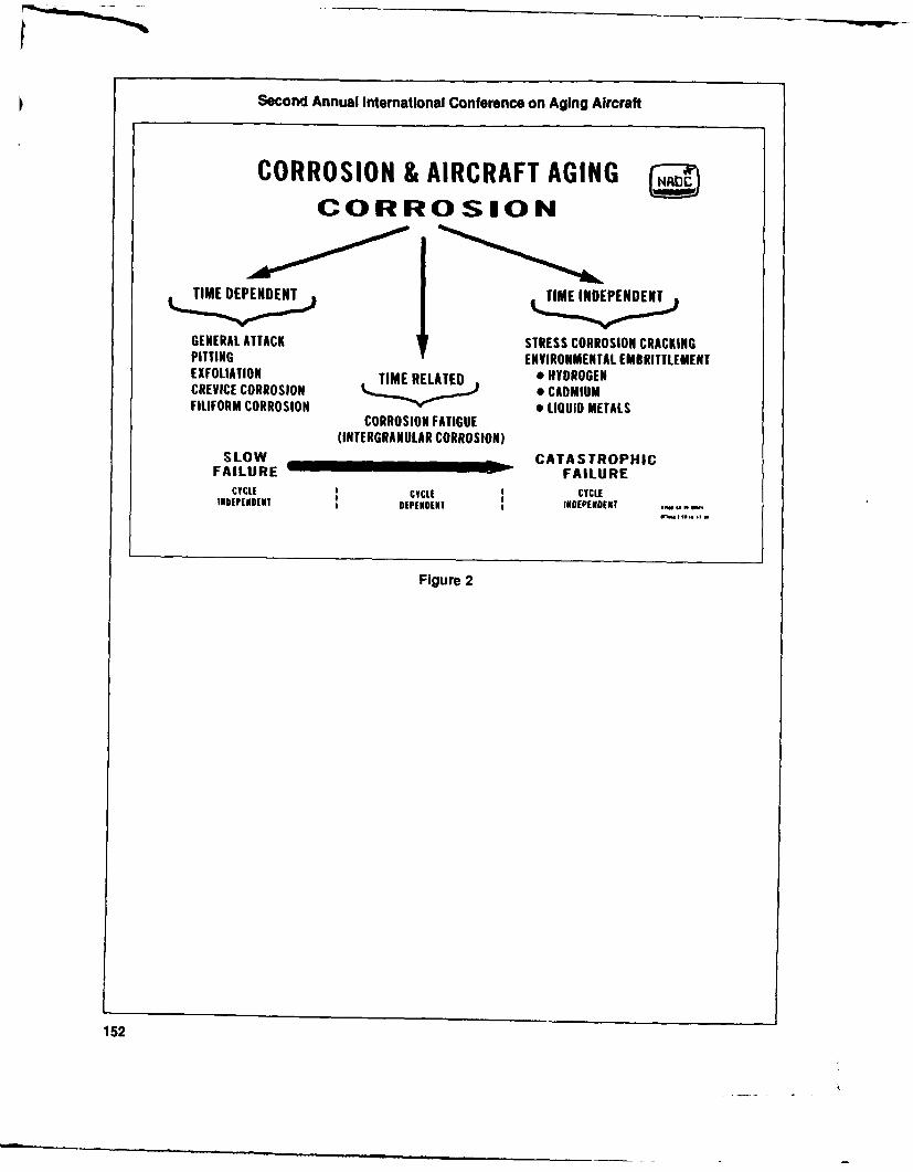
Second Annual International Conference on Aging Aircraft
CORROSION & AIRCRAFT AGINGCORROSION
TIME DEPENDENT TIME INDEPENDENT
GENERAL ATTACK STRESS CORROSION CRACKINGPITTING ENVIRONMENTAL EMBRITTLEMENTEXFOLIATION TIME RELATED * HYDROGENCREVICE CORROSION CADMIUMFILIFORM CORROSION 9 LIQUID METALS
CORROSION FATIGUE(INTERGRANULAR CORROSION)
SLOW CATASTROPHICFAILURE FAILURE
CYCLE t CYCLE CYCLEI E DEPENDENT INOEPENDENT
Figure 2
152

Corrosion
J. A. MARCEAU
Principal EngineerBoeing Commerical Airplanes
I would like to thank you for inviting me to and there were a number of survey findingsthis conference. It's a pleasure to stand here that came out of the investigation. The mostand talk to this group of people involved in the significant was corrosion. It varied significantlyaircraft industry, between operators and within an operator's
I've spent a fair amount of time in recent fleet.years with the aging fleet problems. What I Airplanes that were in corrosion preven-want to share with you today are some of the tion programs from the very beginning of serv-highlights of what I've seen as a manufacturer ice had very few corrosion problems as theyover the years as a result of the aging fleet aged. Repairs may be required more frequentlysurvey that Boeing conducted in the last two or if the corrosion program was implementedthree years. I'm going to talk about the basic later in the life of the aircraft - then the opera-corrosion control practices that we have been tor could expect to continue to have corrosionusing on aircraft over the last 20 years. When but at a lower level than if they did not doI'm finished you will have an understanding of anything.what we've done in the past and what we're In a few cases corrosion had progressed todoing today. the point where extensive repairs were re-
Normal signs of age are usually wear and quired. Also, we found that washing, if donefatigue. These are somewhat predictable and properly, removes corrosion-inhibiting com-can be accounted forby the airline maintenance pounds that then have to be replaced.program to preclude major structural prob- There are a number of causes of corrosionlems. But corrosion is a very insidious prob- and these start right from the very beginning oflem. The only thing you can be sure about with airplane design. (See Figure 1) For example,corrosion is that you're going to have it. But you could design good drainage into the air-you cannot predict how severe it's going to be. plane, which will help, or you could not, which
Boeing conducted the aging fleet survey can create problems in the life of the aircraft.
153
dh-

Second Annual International Conference on Aging Aircraft
CONTRIBUTING CAUSESOF CORROSION
-F--- - I
IFISIll A l 'I .K i MAIN'..NAN ' IIlASIC I,:ESIN FThIIRAION CON'AMINATION - I'IOII,:M ARE:AS
-PIor~ diaimage +Chilipiing •Lavatory spillage -Neglect
( Icv ices Scraces - Galley spillage - 1lirqnr r ,liairsS1 ess -Icaks around fastenters - Chemical spills - Poor cownlsioli conliolI )issimnilai nircials - Abrasion, - Mercury Ir-ograrn (ir lack of
- Ijirish syslen - Dcsposils - Fire residues impleietlaliOlr- MaIC IIs sclccirt1 - Age - IrvrnIiing
ENVIIRONMENTrAL
CONDITIONS OI NP14(OCESSING WITIIIN AII-PIANES ENVIIRONM INT
- 6 lri fillishiltg roU CSS1S3 - cotrldensalioll - Seacosasl- Blontdlling process - Ailhmals - lropical
I I1 iailiig - F~ish - I luillility- Assemibly - Micrubial growtd - lItltsitial
Figure 1
Stress corrosion cracking problems result from mals and a tremendous amount of condensa-the use of materials that are stress-corrosion tion. A lot of air carriers carry seafood in thesensitive. cargo holds. These containers leak quite often
Next you have the manufacturing process- and the essential ingredient for severe corro-ing situation. What's on the design drawing sion, plain common salt, is there. That can be ahas to be done in manufacturing, but if there big problem. You can also have microbial ef-are any manufacturing deficiencies, they can fects, particularly in fuel tanks. The fuel canalso affect corrosion. Additionally, you have support microbes and the byproducts creatematerial finishing processes that are very, very corrosion.critical. Once the aircraft is delivered, it's in the Then you have accidental contaminationhands of the operators and there are a number such as lavatory spillage and galley spillage.of factors that influence corrosion. You can These provide good electrolytes for corrosion.have finish deterioration, chipping, scratching, I'd like to share an incident that I observedbreaks in the paint, abrasion, or deposits. Just back in the late 1970s. We had delivered ageneral age of the finish can enter into the brand new 727 to an operator. It was only a fewproblem. You also have environmental condi- months old and was down in Miami when ittions within the airplane. had a fire on board while sitting on the runway.
For corrosion to occur, there is one element It burned through the crown of the 43 section.that you need, and that's water. However, The plane was ferried back to Seattle and itwater cannot be eliminated from the airplane was repaired. I looked at the structure severalsince there is always condensation. weeks after the fire and the smoke residue that
Condensation provides the carrier for the had condensed on the stringers, frames andelectrolyte that's going to cause corrosion. That throughout the entire fuselage was alreadycan be compounded if the airline carries ani- causing corrosion.mals. There is a lot of water given off by ani- We had to wash it out, spray it down with
154

J. A. Marceau
a neutralizer, and then we sprayed it with a As a result of our general experience withcorrosion inhibiting compound. Even with a corrosion reports and the aging fleet survey,small fire, the smoke residue can be very, very we have a number of areas of concern where weharmful. have most of the corrosion problems, and rather
Last but not least, is the maintenance area. severe problems at times.How the operator conducts his maintenance Areas of concern include the galley, underprogram, how he trains his people, and his the lavatory, at pressure bulkheads, near en-awareness of corrosion problems plays a tre- tryways and cargo doors, in bilge areas, bellymendous role in how badly corrosion will occur. skins, stringers and lap splices.
In the aging fleet survey we found that the When the lap splice delaminates, if the hotmost significant factor in the corrosion prob- bond is a marginal bond, you can have delami-lem of airplanes was the operator's mainte- nation of the bond material in the chem millnance program. His corrosion control program pocket and that's a perfect site for crevice cor-and how well he carried it out, not the geo- rosion.graphic location or the flight profiles or whether The lap is exposed to the exterior environ-or not there are sea coast or industrial environ- ment, which is a rather aggressive environ-ments involved was the most significant factor. ment. There are industrial pollutants, salt and
I'd like to touch briefly on various types of so forth in the environment that ingress throughcorrosion. Perhaps the most common form of the lap splice, causing that particular area to becorrosion in an airplane is just simple crevice quite vulnerable on the 737.corrosion where water and the electrolyte get Another problem area is in the wings. Thein between two parts. spar buildup areas have a lot of crevices where
Perhaps one of the most serious forms of waterand electrolytes would get in and we hadcorrosion is intergranular corrosion (exfolia- a lot of corrosion of spar cords, webs and wingtion), where a lot of the structure is rendered skin planks against the spars and on the em-useless with minimal amounts of consumption panage.of the mual itself. Most of this corrosion takes The 747 has a very large sump area at theplace in the grain boundaries, in the grain rear spar of the wing center section and westructure itself. The grain itself is not being have a lot of drains incorporated thee to re-corroded substantially. move the water. Now, if that area is not prop-
Another very detrimental form of corro- erly maintained and water sits in what we callsion is stress corrosion cracking. You can't the guppy pond, you can have rather severealways see the crack, but it's there. When you corrosion in that area. Someone found a deadhave stress corrosion cracking, there is very frog in a 747 in that area.little consumption of metal involved but the Another common corrosion area is pin jointsstructure itself is rendered almost useless be- where bushings are pressed in a bore of a hole.cause of the loss of structural integrity. Water gets in around the bushings if they are
Pitting corrosion can create fatigue cracks too loose and not sealed properly and you getor stress risers which result in fatigue cracks. corrosion inside those bores. That's prettyYou can have that in the bore of a hole or common whether it's aluminum or steel.perhaps even on the skin where you have Over the years we've learned a lot aboutenough pits occurring that could result in fa- what causes corrosion and we've done a lottigue cracking. over the years to improve the corrosion-prone
Another initiator of corrosion is dissimilar areas of our airplanes.metals, such as having an aluminum nickel The basic design philosophy today is quitebronze bushing in an aluminum housing. a bit different than 20 years ago, from the
There are other forms of corrosion that corrosion standpoint. Some of the significantaren't as destructive such as general corrosion, changes deal with materials selection. (See Figurefiliform corrosion and so forth. 2) The two materials on an airplane that are
155

Second Annual International Conference on Aging Aircraft
* Materials selection 0 Personnel training
* Effective drainage 0 Continual use of corrosion inhibitors
* Finish system selection 0 Planning forcorrosion and factoringSystem = Surface treatment process in the time to clean up corrosion+ primer/enamel early during "C" and HMV checks
* Elimination of crevices by faying 0 Accessibility to the structuresurface sealing
• Use of corrosion inhibiting compound Figure 3- Preventive Maintenance
Significant Factors
Figure 2 - Design Philosophy From the preventive maintenance end, what
Significant Factors the airline has to do is have good personnel
training, use corrosion-inhibitors on a continu-really prone to corrosion are aluminum and ous basis and plan for corrosion in their main-steel. I'm concentrating mainly on aluminum tenance programs. Plan for it because it's goingbecause that comprises about 80 percent of the to exist. (See Figure 3)aircraft structure, although steel has basically Accessibility to structure is also very im-the same problem. portant, as is cleaning. However, if you do too
If you build an airplane that's not going to much cleaning, you have to reapply inhibitorscorrode, you probably couldn't fly it because it and regrease the structure, otherwise you runwould either cost too much or it would be too into problems.heavy. But we make a lot of material compro- In summary, corrosion of airplanes is amises based on weight, cost, function, and combined effect of materials selection, designreliability to build an efficient structure. details, processing, finishes, maintenance pro-
The significant factors beyond that become grams and the operational environment. (Seeeffective drainage, finish system selection, and Figure 4) The thing I want to stress here is thatelimination of crevices. The way we do is this is the airplanes we build today are totally differ-we surface seal - and use corrosion-inhibiting ent than the ones that are in the aging fleetcompounds. today. Their corrosion performance should be
We have made corrosion improvements on tremendously better.the 737, and today we have a tremendous However, one must keep in mind that cor-number of improvements on the current pro- rosion is still going to occur and you have toduction 737s as well as 747s. The newly de- keep looking for it. You cannot slack off onsigned 767s and 757s have these improvements your corrosion prevention programs until weincorporated. build up a base, a history on these newer
airplanes.
156

J. A. Marceau
Corrosion of airplanes is the combined effect of:- Materials selection- Design- Detail processing/finishing- Maintenance programs- Operational environments
Airplanes manufactured today will have fewer corrosion problems than those inthe current aged fleet because of:
- Significant design and corrosion protection improvement- Operators increased awareness of their role in preventive maintenance
Maintenance and corrosion control programs will still play a major role in thecontrol of corrosion as airplanes age
Most significant factors in controlling corrosion:- Drainage- Sealing faying surfaces in corrosion prone areas- Finish system- Liberal use of corrosion preventive compounds- A good corrosion control maintenance program
Figure 4 - Summary
157
Corrosion Control
CHARLES HEGEDUS
Team Leader, Organic Coatings, Aerospace Materials DivisionNaval Air Development Center
Figure 1 indicates the relative corrosivity of rosion and to try and illustrate how that tech-several environments. We show an industrial nology could be transferred to the commerciallocation and a couple of sea coast locations. The arena.aircraft carrier is two or three times more corro- Obviously, the first place to start is withsive an environment than these other areas, design. When the Navy is going to build air-indicating that this is truly one of the most craft it builds design requirements into thecorrosive natural environments known to man. contract. We specify design documents and
One example of a severe location is the guidelines. We very heavily depend on designIndian Ocean (see Figure 2). Through the months evaluations and reviews where we go out andof May and August there are continuous over- observe how they're building aircraft or air-cast skies, high winds and temperatures rang- craft components. Some documents addressing from 80 to 90 degrees Fahrenheit. Relative what the Navy is looking for in corrosion pre-humidity is 80 percent or higher during the day vention and control.and close to 100 percent at night. There is a There are three levels of maintenance withincontinuous mist of salt particulates in the air. the Navy. The first is the organizational level.
What I'm showing here is that the Navy This is the squadron, the people who are actu-performs in an inherently corrosive environ- ally hands-on, day-to-day, every hour. Essen-ment. Dr. DeLuccia's depiction of corrosion tially they are performing maintenance fordamage illustrates that corrosion is a thermo- equipment that is still on the aircraft. Whendynamically and kinetically preferred process, they spot some corrosion, they try to remove itwhich means that corrosion prevention and tosomeextentandapplycorrosion-preventivecontrol need to be a continuous process. compound. It's a very quick but effective means
My objective today is to describe how the of a continuous day-to-day type of maintenance.Navy approaches its efforts in preventing cor- If there is a major piece of equipment that's
158

Charles Hegedus
The continuous southwest monsoonduring the months of May through
. -,. August produces extremely high hu-. "" A1904midity and low ceilings. The weather
during this period is unchanging.
74 - fA.l.. Overcast - 1000 to 1500 feet
* Winds - Southwest at 10-20 knots
17 ,.m,.a Temperature - 80_900 FC A11111
R.H. - 70-89% Day
95-100% Night
TIME WIOUIWRD TO PRODUCE SEVERE IXFO TI*O IN 2124 0.5" Continuous salt/particulate mist in thePtATF FAT TREATEO TO OF SUscrPTII TO FIXOUATION air up to 3000 feet
Figure 1 - Corrosivity Simulation Figure 2 - Environmental Conditions inof Aircraft Environment Indian Ocean
damaged, or something that needs to be re- support to ensure that corrosion prevention/placed or repaired, itcanbe taken off theplane. control receives a priority for timely accom-The part goes to an intermediate maintenance plishment." Greater than 90 percent of theactivity. The extent of the repair effort is at a sailors who work in the aviation branch of themuch higher degree and level of sophistication. Navy receive some form of corrosion control
Finally, there is the depot level. This is training. It doesn't matter what their job is;where the entire aircraft is brought into a depot they receive corrosion control training. That isand is put through a major overhaul. Navy Navy policy. To state it briefly, corrosion isaircraft are, in many cases, originally designed everybody's business in the Navy.to go fora depot overhaul approximately every Corrosion documentation forms are usedfour years. by the organizational and intermediate level
We have a good handle on what is causing people to keep very fine records of when andcorrosion and the fleet is doing a good job on a where they work on an aircraft. They docu-day-to-day basis. Because of this, depot inter- ment exactly what is done to the aircraft. Thisvals have been increased to five, six, and possi- gives engineers a good handle on what is oc-bly seven years. When an aircraft's depot cycle curring, which might indicate why it is occur-is due, engineers from the depot go out and ring, and eventually how it can be stopped.inspect the aircraft, and if they feel it can go for There is now a huge data base on this type ofanother year without any problems, they ex- information.tend the depot cycle a year. That will continue There are 89 intermediate maintenanceuntil the plane essentially needs to be rebuilt. activities. Most of these are on shore, but there
To emphasize the importance that the Navy is an IMA on each aircraft carrier. 127,000 re-puts on corrosion control, let's listen to this pairableitemsareprocessed permonth; 94,000policy statement. "Each command shall place are ready for issue, and 64,000 are repaired perspecial emphasis on the importance of the month. But the Navy still has its corrosioncorrosio-' control program and lend its full problems. It's a continuing battle.
159

Second Annual International Conference on Aging Aircraft
Figure3showsournewestaircraft, anF/A- what we operate in on a continuous basis. In18, which obviously doesn't relate to a com- the Navy we address this issue from a full-muter aircraft, but it illustrates that even though spectrum approach of fundamental researchwe have a good handle on what is going on, we and development, design and procurement,still have problems. and maintenance activities.
One area that I'd like to point out is the In our laboratory, we simulate, to somedorsal longeron where there is extensive pit- extent, the aircraft carrier environment. Weting. It's really amazing. This corrosion proba- have a fairly extensive program where we mountbly starts soon after the aircraft is built, to tell exposure racks onto aircraft. This allows us toyou the truth. Essentially, this area consists of expose specimens and study how they cor-aluminum and some graphite epoxy compos- rode; the mechanisms and the time to failure; etite. There is also some copper and silver. You cetera. We also try and simulate that in the lab.see the disadvantages. I guess one of the ad- One particular chamber we use is a saltvantages is that it probably could act as a spray/SO2 chamber that we quite frequentlysecond battery, if the aircraft ever needed it. use in investigating corrosion phenomena. Of
There have been about four fixes to this so course, we also do a battery of electrochemicalfar, and we always end up with a corrosion and other types of exposure studies.problem. There must be other reasons why it Figure 5 is a schematic of a stress corrosionkeeps occurring. But this is an example of cracking experiment. Obviously, if you have asomething that could really have been pre- crack, there is always a possibility of stressvented during design, and now the sailors corrosion cracking. It is possible to analyze thishave to deal with it on a day-to-day basis. situation, and this is what we're doing, evalu-
There are obviously quite a number of ating this phenomenon from a fracture me-corrosion-prone areas on this P-3 aircraft. (See chanics standpoint. Our objective is to developFigure 4) inhibitors to prolong or stop initiation or pro-
I'll mention a little story about one of the long propagation of any stress corrosionareas. It's an antenna, which is located on the cracking.underbelly of the aircraft. The antenna door Another phenomenon that is receiving a lothassomebondingstripswhicharecopper, and of attention at this conference is fatigue. Thethey attach to aluminum. Obviously, there's a upper curve of Figure 6 is a fatigue graphcorrosion problem there. That really was the (stress versus number of cycles) fora specimenobvious problem. As it turns out, right above that is exposed in "normal" air. Note that mostthe door there is a battery which has a tendency materials have an endurance limit. This endur-to leak onto the antenna. ance limit tells the design engineer that he can
It's hard to understand how people design design to that endurance limit and feel fairlythings like this, but it happens. secure that the part won't fail.
As Dr. DeLuccia mentioned, we are in the Unfortunately, when you expose that sameAerospace Materials Division at the Naval Air material to a corrosive environment, the fa-Development Center, and what I'd like to do is tigue curve drops down. This figure says twodescribe how we help the Navy in addressing things: One, not only does the number of stress-its corrosion problem. to-cycles curve drop dramatically, but it also
We provide the research and development says that there is no "design limit." So noand fleet support to assist everything from matter what you do, you can't design the fa-design to what goes on on a daily basis. I guess tigue failure out of the system, unless youit's in my job description to say that we are the maintain and consider this on a daily basis.best in the world at what we do. That sounds One approach we are working on is tolike boasting, but in a sense it's true, because develop instrumentation to test for the pres-we're forced to be. If you think about it, no ence of hydrogen in high-strength materials.airline or no other "air force," performs or What we're worried about is hydrogen embrit-operates in an environment anywhere close to tlement.
160
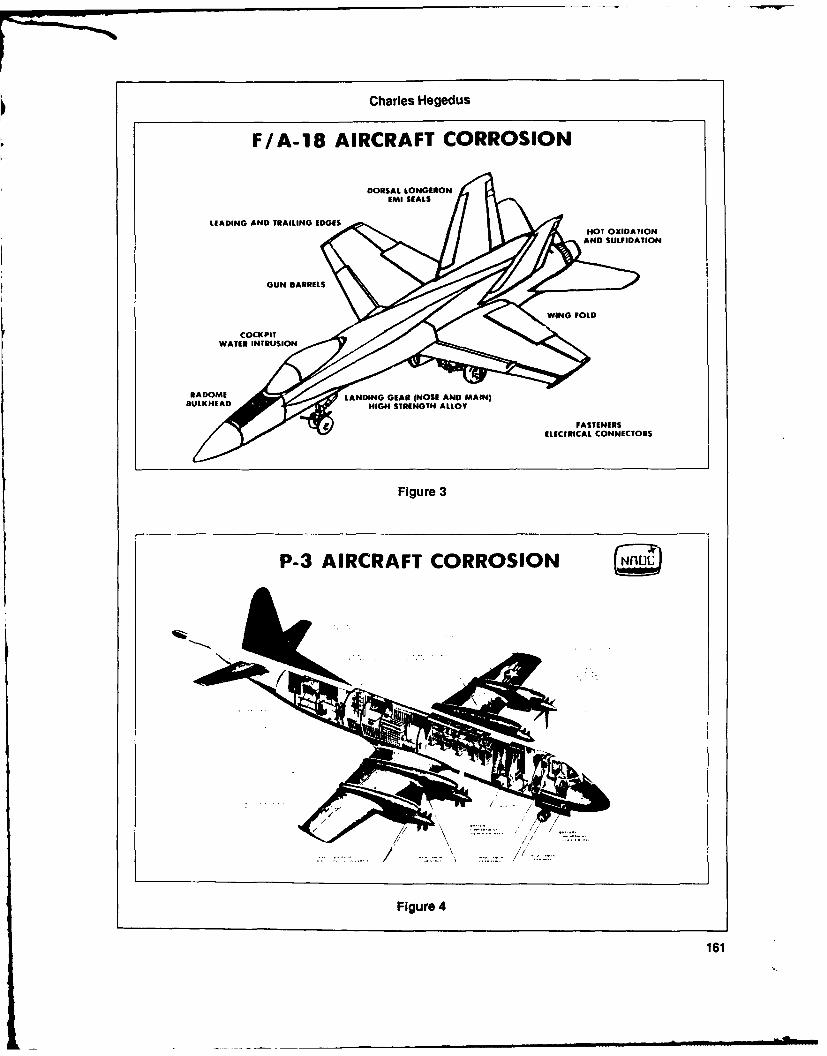
Charles Hegedus
F/A-18 AIRCRAFT CORROSION
DORSAL ,ONGEIION
LEADING AND TRAILING EDGES HOT OXIDATION
AND SULFIDATION
GUN BARRELS
WATER INTRUSION
RADOME // LANDING GEAR INOSE AND MAIN)BULKHEAD~ y HIGH STRENGTH ALLOY
FASTENERSELECTRICAL CONNECTORS
Figure 3
P-3 AIRCRAFT CORROSION
\%
/ /
Figure 4
161

Second Annual International Conference on Aging Aircraft
STRESS CORROSION CRACKING ogc.CORROSIVE
S ENVIRONMENT
STATIC
Eli STRESS
FRACTURERAIMECHANICS
FLAW ORIENTED FAILURE ANALYSIS
WITH CORROSION
Figure 5
IN AIR
S ENDURAN^CE - - - - - - - -- LIMIT
CORROSIVE
ENVIRONMENT
NUMBER OF CYCLES TO FAILURE --- a
Figure 6
162

Charles Hegedus
This instrumentation is not being used on a Corrosion preventive materials such ascontinuous basis, but we have several proto- AML-350, AMLGUARD, and WDP are sometypes and we're checking them out in the fleet. of the materials that are used in the fleet on a
Figure 7 addresses some of the materials daily basis. Essentially, they are corrosionthat we're working on. We have developed a preventive compounds that displace water.mixture or a cocktail, if you will, of inhibitor They are designed to be touch-up materials.materials. We call it DNBM; that's short for a And of course, when you're taking care of annumber of inhibiting compounds we mix to- aircraft on an aircraft carrier, even on a nice daygether. When they're together they address a there's a lot of humidity, there's a lot of conden-number of corrosion mechanisms, and there sation. Even if you prepare the surface beforeare probably some synergistic effects when applying a paint or a corrosion preventivethey're mixed. compound, there's still a good possibility that
The figure shows that the treatment with there's some water left on the surface.DNBM on a continuous basis shifts the crack So these materials were designed specifi-velocity versus K (stress corrosion cracking) cally to address some surface chemistry issues.over to the right fairly dramatically. When you apply the material, if there happens
On the other graph, we have corrosion to be water on the surface that's being coated,fatigue, and again, we see a shift in the curve thecompoundwilldisplacethewaterand formwhen DNBM is applied on a continuous basis. a barrier between the environment and the
I guessIshouldmentionthat this particular substrate. This type material ranges from soft,inhibitor mixture, is still in the research phase. greasy-like materials, to actual paints, and theyIt has been developed, but now we are trying to are being used on a continuous basis out in theapply it by putting it into corrosion preventive field.compounds, paints, greases, lubricating fluids, We recently developed what we call a self-et cetera. priming top coat. Our name for it is "Unicoat."
ARRESTMENT OF ENVIRONMENTALCRACKING BY DNBM IN AIRCRAFT ALLOYS
(HIGH HUMIDITY & SALT SPRAY)
STRESS CORROSION CRACKING CORROSION FATIGUE
A tC CONTROL CONTROL
TWITH 0NRM
V WTIH "N-
to /
C
T A. I ____, _______I ________
y Ki-( IK i$( A K
STRESS INTENSITY FACTOR
FOR ALL HIGH STRENGTH STEELS AND ALUMINUM ALLOYS
Figure 7
163

Second Annual International Conference on Aging Aircraft
Normally, when aircraft are painted (commer- Figure 8 is a list of manuals that we control.cial aircraft or military aircraft) a corrosion- The manuals address a number of issues: air-preventive primer is applied first. It's an epoxy craft cleaning and corrosion control, avionicsmaterial with some corrosion inhibitors and cleaning and corrosion prevention, preserva-then a polyurethane top coat is applied. The tion of aircraftand ground support equipment.primer is there to promote adhesion and en- These manuals are used on a daily basis by thehance the corrosion inhibition properties of the fleet. They also provide a direct and officialpaint system. The top coat is primarily there for means of transferring our technology from anaesthetics, but also for chemical resistance and R&D center to the person who is touching andweather resistance. working on the aircraft every single day.
Unicoat was designed to replace those two This technology, the manuals, the materi-coatings with just one coat. It contains some als and the specifications are available for tran-corrosion inhibitors, but it also can be tailored sition. As a technologist, I feel that what I doto a number of different colors. And it has just isn't worth it unless someone is actuallyobvious implications as far as weight savings, using the technology, whether it's in the mili-application, manpower, time and material tary or in the commercial area.savings. Also, it contains no chromate materi- As far as naval aviation corrosion control isals, and has lower volatile emissions, which concerned, there are three major issues thathas huge environmental implications. This is need to be continuously addressed; and that isan enormous issue in reworking aircraft these design, preventive and corrective actions on adays. continuous basis, and a continuous research
This particular coating is not in a full-scale and development program to address state-of-production phase yet. However, we have painted the-art issues. If a new alloy comes out, we11 aircraft, four of which were painted approxi- need to address it. New inhibitors are beingmately two years ago. Some aircraft that have introduced every day that could be appropri-seen nine months of sea duty, look as good or ate for paints and corrosion preventive corn-better than those that used the standard paint pounds.system. So the Navy definitely sees the poten- The technology that we are developing istial of saving a lot of money with this particular definitely available for transition to the com-coating, without sacrificing corrosion inhibi- mercial community. (See Figure 9)tion properties.
164

Charles Hegedus
Contain technical information detailing corrosion prevention/control proceduresand required corrective acions.
I - NAVAIR 01 -1 A-509 - Aircraft cleaning and corrosion control
II- NAVAIR 16-1-540 - Avionics cleaning corrosion/prevention control
III - NAVAIR 15-01-500 - Preservation of naval aircraft
IV - NAVAIR 15-02-5 - Preservation of aircraft engines
V - NAVAIR 17-1-125 - Ground support equipment cleaning and corrosion control
VI - NAVAIR maintenance publications peculiar to specific aircraft modelsand related equipment
Figure 8 - Techricai Manuals
AGING AIRCRAFT PROGRAM NROC
TRANSFER OF CORROSION TECHNOLOGYFROM DOD DOT(NAVY) (FAA)
TRANSFER OF:
(1) KNOWLEDGE (CORROSION WORKSHOPS/ COURSES )(2) PRODUCTS (COATINGS, CORROSION PREVENTIVES)(3) PROCEDURES (ADV. CIRC., MANUALS)
TECHNIQUES (LEVELS AND FREQ. OF MAINT.)
MAINT. INTERVALS AND PERFORMERS
UPDATE ADVISORY CIRC.; START MANUAL PAYOFFSAMLGUARD, UNICOAT ETC. JNAESU CORROSION COURSE ADAPTED FOR FAA INSPECTORS
Figure 9
165

Corrosion Control
ROBERT DEROSA
Standards and Systems Division, United Airlines
Good afternoon. I've worked forUnited for airframe by minimizing the amount of struc-23 years, so we've had plenty of time to develop tural corrosion repairs required.corrosion programs. We've had Boeing 727 air- The optimum program would be one whereplanes from the start, and B-737s from the start. the only repairs necessary would be restora-
United has a fleet of well over 400 airplanes. tion of protective finishes. This of course is notWe operate throughout the United States, North achievable. However, it is possible to maintainAmerica and the Far East. These airplanes vary the integrity of the airframe indefinitely by anin age from brand new - we're getting deliv- effective treatment and prevention program.eries every week- to well over 25 years old. So Treatment of corrosion depends primarilyconsequently, the degree of corrosion protec- on the amount and severity of the corrosiontion incorporated into design of the airplane found. In most cases, the corrosion is fairlyvaries from virtually non-existent with some of localized and easily repaired. Where corrosionthe early airplanes, to fairly extensive on the blend-out exceeds structural repair manuallater airplanes. limits, localized repairs or replacement of parts
Because of this, our corrosion control pro- is used to restore structural integrity.grams are tailored to individual fleets, depending The exception is adhesive bond corrosion,on age, prior experience, flight environment which I believe everybody here is well awareand degree of corrosion protection incorpo- of. This type of corrosion is generally wide-rated into the airplane prior to delivery, spread and difficult to contain. In most cases,
In addition to maintaining all the protec- skin panel replacements and extensive skinlaptive finishes, we apply corrosion-preventive repairs are the only effective method of repair.compounds, such as LPS-3 or Dynol, to all When this occurs, we take advantage of theareas on periodic visits. Our periodic mainte- opportunity to upgrade the corrosion protec-nance visits are established on the basis of tion of the underlying structure. Stringers andmaintaining the structural integrity of the frames are repaired or replaced as necessary,
166
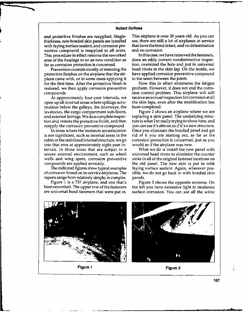
Robert DeRosa
and protective finishes are reapplied. Single- This airplane is over 20 years old. As you canthickness, non-bonded skin panels are installed see, there are still a lot of airplanes in servicewith faying surface sealant, and corrosion pre- that have the bond intact, and no delaminationventive compound is reapplied to all areas. and no corrosion.This procedure in effect restores the reworked In this case, we have removed the fasteners,area of the fuselage to an as-new condition as done an eddy current nondestructive inspec-far as corrosion protection is concerned. tion, oversized the hole and put in universal
Prevention consists mostly of restoring the head rivets in the skin lap. On the inside, weprotective finishes on the airplane that the air- have applied corrosion preventive compoundplane came with, or in some cases applying it to the seam between the joints.for the first time. After the protective finish is Now this in effect eliminates the fatiguerestored, we then apply corrosion preventive problem. However, it does not end the corro-compounds. sion control problem. This airplane will still
At approximately four-year intervals, we receive an annualinspection for corrosion at allopen up all internal areas where spillage accu- the skin laps, even after the modification hasmulates below the galleys, the doorways, the been completed.lavatories, the cargo compartment sub-floors, Figure 2 shows an airplane where we areand external fairings. We do a complete inspec- replacing a skin panel. The underlying struc-tion and restore the protective finish, and then ture is what I'm really trying to show here, andreapply the corrosion preventive compound. you can see it's almost as if it's a new structure.
In areas where the moisture accumulation Once you eliminate the bonded panel and getis not significant, such as internal areas in the rid of it you are starting out, as far as thecabin or the stabilized internal structure, we go corrosion protection is concerned, just as youinto that area at approximately eight-year in- would as if the airplane was new.tervals. In those areas that are subject to a What we do is install the new panel withsevere external environment, such as wheel universal head rivets to eliminate the counterwells and wing spars, corrosion preventive sinks in all of the original fastener locations oncompounds are applied annually. the old panel. The new skin is put in with
The indicated figures show typical examples faying surface sealant. Again, wherever pos-of corrosion found on in-service airplanes. The sible, we do not go back in with bonded skinrepairs range from relatively simple, to complex. panels.
Figure 1 is a 737 airplane, and one that's Figure 3 shows the opposite extreme. Onbeen reworked. The upper row of the fasteners the left you have extensive light to moderateare universal head fasteners that were put in. surface corrosion. You can see all the white
Figure 1 Figure 2
167

Second Annual International Conference on Aging A;rcraft
~,I.
Figure 3 Figure 5
powder residue built upon the joint. Theactual it's a fairly extensive one. This one is only oncorrosion on this lap, however, in most cases the upper skin. But again, it's almost a fulldoes not exceed the 10 percent limit. In fact, panel-length repair.what we found is that once you clean the corro- Figure 6 shows another 737 panel replace-sion products off the airplane, the actual loss of ment. You can see the rework going on, wherematerial is minimal. However, getting the cor- we are putting in universal head rivets. Therosion products out of thereusuallymeans that next panel down, you can see the skin cut outwe exceed the 10 percent limit because we can- for a corrosion repair. Then we replace thenot control the methods of removal, entire panel.
Figure 4 shows a skin lap repair. What we I'd like to point out that you can see thehave found is that if you are going to repair the condition of the stringers and the frames underskin lap, it's better to just cut the full length of the skin and their relatively good condition.the panel and install a full-length repair dou- When the panel goes back on, we would firstbler on the lap. This eliminates the entire bonded put faying surface sealant back on those framesjoint, and stringers.
Again, you can see above where we are Figure 7 is a better shot of the area. You canreplacing the remaining fasteners with button see where the primer has been reapplied to thehead fasteners in the lap. stringers and the frames. You can see the con-
Figure 5 shows another skin lap repair, and dition of the bonded straps, where all the adhe-
Figure 4 Figure 6
168

Robert DeRosa
Figure 7 Figure 9
sive remains have been cleaned off. The struc- out on these frames and reinforcements haveture is alodined and primed prior to putting on been applied per the SRM.the new panel. The intention is to go back with Incidentally, all repairs that we install,a panel that is non-bonded wherever possible. whether they are skin repairs or extruded angle
Figure 8 is showing you the condition of the repairs, are installed with faying surface seal-panels now. The deep dark purple or plasti- ant between the repair and the primary structure.cized color shows you the delamination. The Figure 10 is some typical cut-out doublerred light spotty areas where you see the white repairs. The reworked areas have been done bypowder residue, which are the oxides, is the reinstalling the universal head rivets.actual corrosion. Up in the upper corner is an Figure 11 is another door doubler, and itindication of where the bond is still good. And shows how extensive the damagecan get whenit's very descriptive of showing the three stages you have corrosion and fatigue cracks buildingofbondedpanelshere.Youhavedelamination, up that extend through all the layers of thecorrosion and good material, external skin and throughout the doublers. It
Figure 9 is showing a galley area. You can also shows you another area that's verysee the pressure dome bulkhead and the area critical-make sure you pull up scuff plates onunder the doorway, which is essentially where a routine basis and make sure that you checkthe galley and lavatories sit, and where you get the area in the entryways of all the doorways.the spillage. The corrosion has been cleaned Figure 12 is a shot that shows the cabin
Figure 8 Figure 10
169
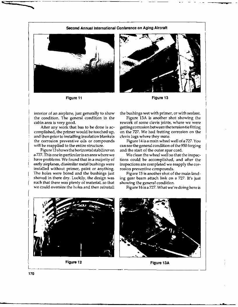
Second Annual International Conference on Aging Aircraft
Figure 11 Figure 13
interior of an airplane, just generally to show the bushings wet with primer, or with sealant.the condition. The general condition in the Figure 13A is another shot showing thecabin area is very good. rework of some clevis joints, where we were
After any work that has to be done is ac- getting corrosionbetweenthetensiontiefittingcomplished, the primer would be touched up, on the 727. We had fretting corrosion on theand then prior to installing insulation blankets clevis lugs where they mate.the corrosion preventive oils or compounds Figure 14 is a main wheel well of a 727. Youwill be reapplied to the entire structure. can see the general condition of the 950 forging
Figure13showsthehorizontalstabilizeron and the start of the outer spar cord.a 727. This one in particular is an area where we We clean the wheel well so that the inspec-have problems. We found that in a majority of tions could be accomplished, and after theearly airplanes, dissimilar metal bushings were inspections are completed we reapply the cor-installed without primer, paint or anything. rosion preventive compounds.The holes were bored and the bushings just Figure 15 is another shot of the main land-shoved in there dry. Luckily, the design was ing gear beam attach link on a 727. It's justsuch that there was plenty of material, so that showing the general condition.we could oversize the holes and then reinstall Figure 16 is a 727. What we're doing here is
V
Figure 12 Figure 13A
170

Robert DeRosa
replacing the two aft-belly skin panels. Theserun from body station 950 to body station 1183,from stringer 26-left to 26-right.
We have a somewhat unique problem onthe 727, in that the bonded panels, unlike the737 where the panels were bonded and thenchemically milled, were not chem milled. Socorrosion preventive compounds do not helpyou very much on a 727. Once the panel isdelaminated and you have corrosion starting,the oils cannot penetrate, bcauze in ;ome casesit would have to travel 12 to 18 inches, and weknow that the range that the preventive com-
Figure 14 pounds can penetrate is not that great.Rather than continue patching the airplanes,
we elected to replace these panels. We startedin about 1972, and went through all of ourdash-1 00 airplanes. We had 90 of them and wereplaced the panels. In some of the early ones,where we couldn't get the single thicknesspanel, we had to go back in with the bondedpanels. In some cases we replaced those panelstwice.
Figure 17 shows the corrosion repair aroundan outflow valve. This is one of the areas whereit is virtually impossible to prevent corrosion.When you get spillage out of the service tanksfor the lavatories, all you can really do is makesure you have a very effective corrosion protec-
ltion program and do periodic inspections toensure the integrity of the area.
Figure 15 Figure 18 is the center engine inlet duct areaof the 727.
Figure 19 is related to the stress corrosion
Figure 16 Figure 17
171
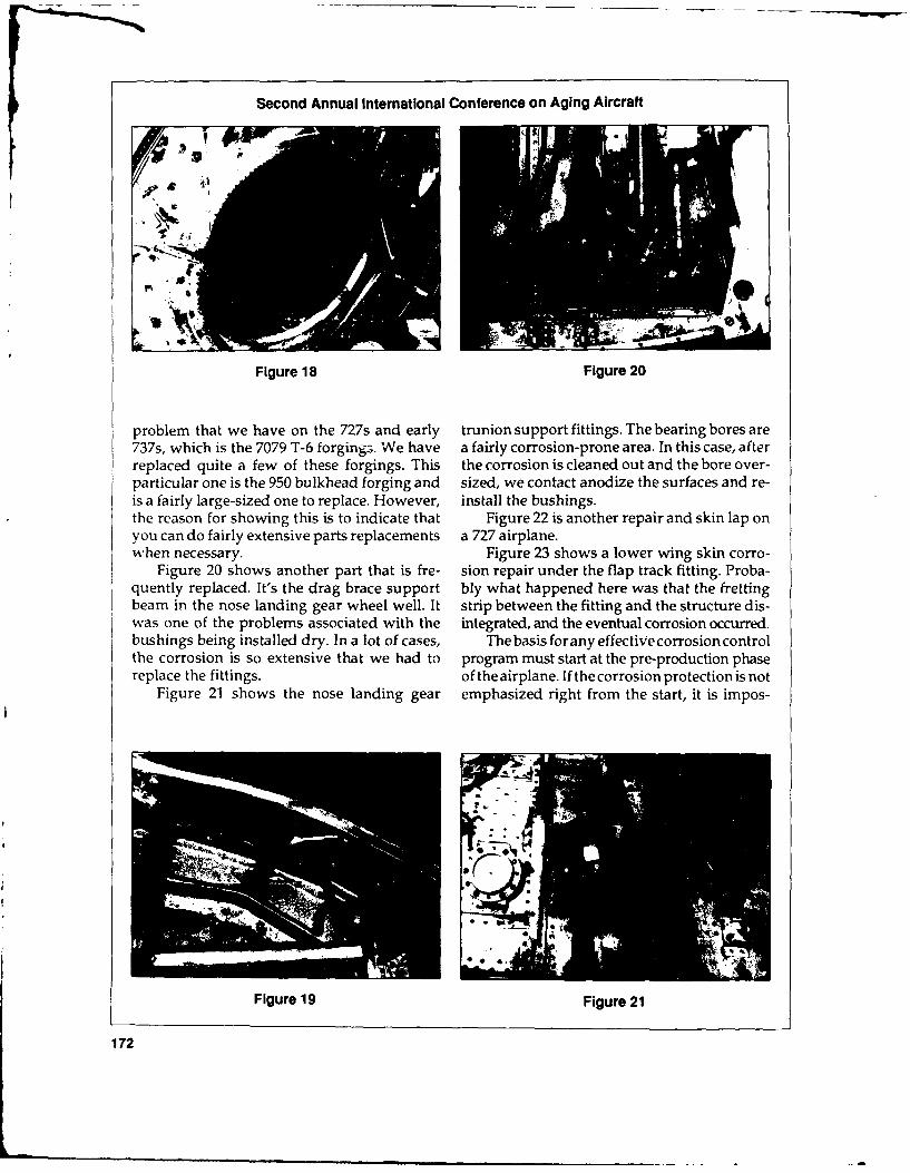
Second Annual International Conference on Aging Aircraft
Figure 18 Figure 20
problem that we have on the 727s and early trunion support fittings. The bearing bores are737s, which is the 7079 T-6 forgings. We have a fairly corrosion-prone area. In this case, afterreplaced quite a few of these forgings. This the corrosion is cleaned out and the bore over-particular one is the 950 bulkhead forging and sized, we contact anodize the surfaces and re-is a fairly large-sized one to replace. However, install the bushings.the reason for showing this is to indicate that Figure 22 is another repair and skin lap onyou can do fairly extensive parts replacements a 727 airplane.when necessary. Figure 23 shows a lower wing skin corro-
Figure 20 shows another part that is fre- sion repair under the flap track fitting. Proba-quently replaced. It's the drag brace support bly what happened here was that the frettingbeam in the nose landing gear wheel well. It strip between the fitting and the structure dis-was one of the problems associated with the integrated, and the eventual corrosion occurred.bushings being installed dry. In a lot of cases, The basis forany effective corrosion controlthe corrosion is so extensive that we had to program must start at the pre-production phasereplace the fittings. of the airplane. If the corrosion protection is not
Figure 21 shows the nose landing gear emphasized right from the start, it is impos-
Figure 19 Figure 21
172

Robert DeRosa
Figure 22 Figure 23
sible to ensure a corrosion-free airplane through percent inspection of bonded skin panels forits life. delamination is necessary prior to airplane
With that point in mind, we stress corro- delivery.sion prevention in all new airplane design The program I have outlined is a briefreviews. in general, our goal is to ensure that all summary of United's approach to corrosionstructue below the floor line be assembled control programs. With some minor differ-with faying surface sealant, and all detail parts ences, I believe the majority of airlines havebe top coated with polyurethane paint before developed similar programs. Our programassembly. adheres closely to the baseline corrosion pre-
In addition, we try to limit, as much as vention and control program recommended bypossible, the use of bonded fuselage skin pan- the Aging Fleet Task Force.els below the floor line and areas that are This baseline program should alleviate somesubject to severe corrosion environments, such of the concerns associated with operating air-as galleys and lavatories, planes beyond their original design life goals.
Wealsorequirethatallbasicfuselagestruc- Although it is true that protective finishestures be treated with corrosion preventive deteriorate and break down, periodic repair orcompounds. Since bonded structures are our replacement of parts and restoration of protec-most significant concern, we are attempting to tive finishes can ensure the structural integrityconvince the airframe manufacturers that 100 of the airframe.
173

Session IV: NDE/NDI
CHAIRMAN STEPHEN N. BoBo
NDI Specialist, Transportation Systems Center
U.S. Department of Transportation
Introduction individual inspection of thousands of fastenersand bonded joints on each aircraft; and with
Since the Aloha aircraft accident, all compo- current technology, the inspections of the exist-nents of the aircraft industry have made a mas- ing fleet of some 1,600 aircraft will require mil-sive effort to ensure the continued airworthiness lions of dollars. Clearly, a major need exists forof the air carrier fleet under the purview of the improved, more cost effective inspectionFAA. methods.
In an effort to coordinate these activities the As a result of the recommendations fromFAA hosted an International Conference on the conference, a research plan was completedAging Aircraft in June, 1988. in May 1989, one component of which was a far
One problem which became apparent was reaching NDI initiative aimed at developingthat the need exists for improved NDI particu- improved inspection methodologies for the airlarly in the following areas: carrier fleet. The work includes an assessment
of existing methods, a search for relevant meth-" Detection of crack growth as an element of ods not now being fully utilized, and an evalu-
fatigue damage to fuselage structures. ation of emerg;ng technology that might be" Development of improved methodologies brought to bear on the problem. Oversight of
for characterizing integrity in bonded lap the projects related to the initiative is obtainedjoints, through an NDI Working Group (AANWG)
• Identification and isolation of corrosion consisting of representatives from the air car-damage in aircraft structures. rier industry, aircraft manufacturers, acade-
mia, DOD and NASA.Perhaps the major problem, however, is the Figure 1 is a flow diagram containing the
huge scale of the task. Current plans call for the major elements related to NDI.
174

Stephen N. Bobo
Aging AircraftNDI Working Group
Technology Maintenance NewTransfer Inspection & Repair Technology
NDI Technology NDI Equipment SBIR ProposalsSurvey Evaluation I
Survey of NDI I Pressure Test &iAudit D Checks Sample and Test AircraftData Base Specimen Program
I Acoustic EmissionNDI Workshops Infrared
Engine NDI ,-AutoscanLBowdoin QNDE Conf. KNeutron RadiznrannvKAging Aircraft r-Holography
Intl. Symposium NDI Handbooki MoireASNT Workshop -Eddy Current :.magi.g
K PhotogrametrvMemoranda of Review Existing I -Test Data Fus-n
!Understanding Technology
NAVY -DOD NDI HandbooksARMY -Boeirq NDI HandbooksNASA -McD-D NDI SSIDS
-ISU -Bond Tester Evaluation-Eddy Current Evaluation-Human Factors
Figure 1 - NDI Flow Diagram
Technology Transfer FAA engineering and inspection elements foruniformity of practice and effectiveness of pro-
The first task under the NDI portion of the cedures. The framework for this audit is providedAging Aircraft Program has been to assess the by a massive checklist in which all elements ofeffect of baseline aircraft NDI activity, now the inspection are covered; from documenta-being accomplished in two projects: an ongo- tion to training and human factors. The NDIing audit of heavy maintenance checks or "D" portion of the audit checklist seeks to deter-checks, the major periodic inspection carried mine types of inspections, procedures, instru-out by most commercial carriers to fulfill the mentation, training, qualification of inspectorsFAA requirements for continuing airworthiness; and storage and handling of specimens andand a broad based survey of NDI practice, both samples. Data from the checklists are beingin the aircraft industry and in other industries collected, organized and condensed with a viewwhich may have relevant technology, to preparation of a report late in 1990. Mean-
while, NDI data is being reviewed to determineD-checks uniformity and level of quality of the NDI
practice, and to serve as a baseline for potentialUp to 60 heavy maintenance inspections improvements to the system.
are now being monitored by representatives of
175

Second Annual International Conference on Aging Aircraft
Survey of NDI Practice users and industry in general is through sym-posia and workshops. A series of workshops is
The Nondestructive Testing Information being scheduled in 1990, beginning with one inAnalysis Center is currently under contract to April on Structures and Fracture Mechanics.conduct a state-of-the-art survey of NDI as re- Others are planned on Human Factors andlated to its use in commercial aircraft over Corrosion.seven years old. The purpose of the survey is todetermine whether existing technology in otherareas of the industry may be effective in im- Other Activitiesproving the effectiveness of the inspection pro-cedures now in use in the industry. The survey In addition to the above activities, a datawill contain but not be limited to the following base is being maintained of potential bidders inelements: technical areas likely to become fruitful as new
1. Physical principles used, i.e. ultrasonics, NDI initiatives. Those wishing to be on theed current and aided visual bidders list will be requested to provide infor-2. Generalized description of the instrumen- mation about their capability and will betation. A listing of each instrument consid- considered for projects in their areas of exper-tatiod qaliing fof se isstruenitons- tise. Also, a library of articles and up-to-dateered qualified for use, its specifications, dcmnsfo urn ieauei en anapproximate cost and an estimate of the documents from current literature is being main-apploxite ccotandate o the industrytaned and circulated. In addition to work withlevel of its acceptance by the industry, clas- industry, Memoranda of Understanding are insified by physical principle from No. 1 above. effectr a ren otiated i emen
3. A generalized description of the inspection effect or are being negotiated with elements ofprocedure used for each instrument cited DOD and NASA.in No. 2.
4. An assessment of the cost of use of the in-strument, either on the basis of cost per Maintenance Inspection andhour of use, or cost per inspectable unit or Repairunit of area being inspected.
5. An assessment of the future development The FAA has several major tasks in connec-potential of the physical principle from No. tion with its NDI responsibilities in the area of1, and some kind of estimate of the ultimate maintenance and repair. The first task is evalu-limitation of the technique. ation of NDI equipment and procedures;
6. A summary evaluation of other promising supplementary work under this task is the or-techniques form other areas, either DOD, ganization and implementation of a compre-nuclear, utilities or others. This summary is hensive library of flaw samples. The second isheavily biased by considerations of the eco- to assess the NDI needs of the industry innomic pressures found in the commercial engine NDI. The third task is to create guide-aircraft industry, lines for utilization of NDI practice by prepara-
7. A listing of sites on the aircraft where the tion of an FAA NDI Handbook.bulk of the NDI is carried out, and the pre-ferred instrumentation for these inspections.A preliminary document is available now, Equipment Evaluation
and a final report is scheduled for August, Two major short-term inspection problems1990. exist within the aircraft fleet: the need to relia-
bly inspect large numbers of rivets for theWorkshops and Symposia existence of multiple site damage (MSD), andthe ability to inspect extensive areas of fuselageAn important means of obtaining a con- for adhesive bond integrity in the presence of
tinuing technology transfer between the NDI corrosion and other contaminants. With indus-
176

Stephen N. Bobo
try help, various inspection methods are being cedures for utilizing NDI equipment on air-evaluated in an effort to find the most reliable craft structures. Also, it is frequently necessaryand cost effective method for inspection of lap to evaluate fatigue by using complicated struc-joints and other sites in which MSD is likely to tures fully simulating the construction aspectsoccur. Figure 2, from the Boeing 737 NDT and geometry of aircraft in which fatigue hasManual, shows areas in a Boeing 737 that re- been found. Accordingly, in order to meet thequire emphasized inspection. Existing meth- objectives of the aging airplane program, it is aods for detecting adhesive bonds are generally vital requirement to collect and maintain a li-satisfactory in uncontaminated areas, but when brary of simple and complex examples repre-corrosion, its byproducts, or other contamina- sentative of structures found on aircraft. Fig-tion exists in riveted lap joints and doubled ures 4 and 5 are examples of the specimens thatbutt joints, detection of adhesive bond integrity are being collected.becomes unreliable. Accordingly, the FAA is This library is now being assembled at thediligently searching for a more effective method Department of Transportation's Transporta-for inspecting the adhesive bonds in aircraft. tion Systems Center in Cambridge, Massachu-
setts. The specimens will be used to validatenew NDI techniques, compare the effectiveness
Criteria for Determining the of instrumentation, quantify the effectiveness
Effectiveness of Inspection of various procedures and evaluate operatortraining.
The FAA is developing criteria for evaluat-ing the effectiveness of NDI procedures. Ingeneral, these criteria are similar to those found Engine NDIin DOD and in airframe manufacturers' hand-books. They consist of utilizing a set of stan- Several initiatives aimed at on-board en-dard samples, some of which have characteristic gine diagnostics are being investigated along
flaws and some of which have no flaws. The with an assessment of current inspection practice.
samples are inspected by several inspectors,and the number of flaws detected are counted.The number of missed flaws are also counted NDI Handbook(Class I errors) as well as the false positives(flaws averred to be present where no flaws VariouselementsofDODhavemaintainedexist are Class II errors). From the data ob- ahandbookonNDIformanyyears, ashaseachtained, statistics may be derived for a given of the airframe manufacturers. In an effort totechnique and compared with other competing provide guidance for minimum requirementstechniques. Probability of detection (POD) is for such a handbook, to be used by those certi-calculated for a given confidence level, as well fied by the FAA and to promote commonalityas error rate and incidence of Class II errors. of handbookapproach, it is appropriate for theFigure 3 is a typical family of POD curves for FAA to prepare a standardized FAA NDI hand-four commonly used NDI methods. (D. Hage- book.maier, McDonell Douglas, Maintenance Engi- The FAA already has an NDI Advisoryneering Plan, May, 1988) Table 1 is a listing, Circular, but it requires updating to be relevantfrom the same source, of the common NDI to the needs of inspectors in the field. Themethods and their capabilities and limitations, current AC will be reviewed, along with other
handbooks available from industry and DOD.When the review is complete, the FAA staff
Sample and Specimen Program will prepare an outline for the FAA handbookand develop a plan for orderly flow of informa-
Samples and specimens play a large part in tion on relevant NDI procedures into the hand-calibration, training and development of pro- book format. The deliverable from this work
L
177

Second Annual International Conference on Aging Aircraft
NONDESTRUCTIVE TEST
as ,CLFZEA~A
C2ACK 1 R I SaoAC
*YIC' FATIGUE CRACK KI
CRACKPAG IONAIO
178

Stephen N. Bobo
1.0 --
-1 -jj'- EDDY CURRENT
0.8 1 IF - PENETRANT...... RADIOGRAPHY
NO OF -- ULTRASONIC
DETECTED 0.6 'IFLAWS/TOTAL IFLAWS 0.4 I
0.2 - I
0 ....0 0.100 0.200 0.300 IN.
0 1.00 200O 3.00 400O 5.00 600O 7.00 8.00 9.00 Prm
LENGTH OF THIN SPECIMEN FLAWS, 2c
Figure 3 - Proportion as a Function of Length in Thin Aluminum Specimens, Combined Data
MlI I'll[)(I MI'LOYTLD APPLICATION ALIVANWAGfS LASALIVANIAGES
I qIAt OF TO (ION OIF SI Ill All O1F TCT, Il '01011 F TO) 11F IN AWnrAS WIrn If r IF0 II W it IABILHfT DEPENDS UPON THlE ABILITYSTI1ICIUIIAL IIAMAI..I IN ALL MATEIlIAIS MtI HOLS AlIf IMIACI ICAL OTICAL AND EXPERIENCE Of IlE USER ACCESSI
AlLIFUlIIItiEII ENhIANCE flltS MCIPO 111 ILIlY RFQIIIED FOR DIRECT visBILItuy(aORl D0ORF SCOPE
II III MIAN;I D[I .2TION Or SIIIIFACE CItACIIS IN ALL sIM IF TOI lISF ACCUIIATE. FAST. EASY ITEFECT MOST Of OPEN TOSLURFACE ANDPAT rI kS CA.I INI.S. FlIRGIN;S. toI INIEIIIPlLI ACCESSIBLE t0 OrERlAfOR EECf MAY BE-ACl. ) 11 .'All IS. WfCUMENTS COVERED BY SMERARED METAL. PART MUST
BE CLEANED BEFORE ANDAFTER CHECK
I TiI J l, OF TTOII. IAI Cl u(N hf "1l1'A1 It FtC 1IN UlSEFLf fOl CIE CINT'.All Al MWNI TRIAINED0 OPERlATORI lIE QII SENSITIVE'lI4 M IAt [I SIIIlACLS, CI iKS. PI IS. IfIFfS FORlCIIACKS NI If tt IMI]LL CIIUOINAI IONS AND VAIIIA IIONS IN
I Ifli NI Il ItC;IIANIIAIAl CIIIOSII)N ANTD IT VISUIAL Il PUN[ IIIANT MLIICITIS MATERIIAL. SPECIAL PRFlS REQUIRED?ilAl 11A T NT IIII T I:IINI AK DIIVITY FAST. SLNSIIVE VlOllIILE io)11 ACIIAPPI CAl ION REF ERENCEI(1 OMl A-0,IM~MINI 1(111 UIIIMINING SIAfIDAIIDSRIEQUIREDI) 1111 ITAMA4.I I All( A
" Yl 111 1111010 NI lllCIOI(fSIIIFACF TIEPECTS USEFULI fOR CHIECKING rOIICRACKS TRAINEEIOPERAIOR RIEQUIRED, LARGER
II11? Nl I IN MAT TALLIC MATE IllAl . COLHIOSION WIIIEJ)ll REMOVAL OF FAST( Hf RS PROBES NEEDED FOR LOWER FIIEQt*NCYCIIII~i N I IINTIING ANDI SO-ACING Oil DISASSEMBLY OF SUIISIlUXI UE USAGE SPECIALI'1100FI5REQUIRED FOR
EACH APPLICATION REFERENCE STANDARDSREQUIRED
MINK11. Of It C FLON lI TIE LAMINATIONS. DEBIONDS. CAN RE ACCOMPLISHEfI EROTM ONE COSES SENSIIIIT Willi INCREASINGVIDIS AND CIPSIff 1)CORE IN COM SORIFACE DIRECT READING 001 S MAIERIAI. THICKNESS LLECTRICALSOUIRCEPOSIIE ANTI hOUN YCOMB MAFEIIIALS NOT REIR~E PAINT REMOVAI OlR REQUIRED
SPE CIAL SURF ACE PR~eAAl[ONX IAT OFI 11I.TIIN Of INFRNAL FIAWS AND ELIMINAIES MANY DISASSEMBL Y RADIAWIONIIAZAFII TRAINEDOOPERATORS
lIE FEf C IS SIICI A'; CIIACAS. CORROSION. REIJUIIIEMCNWS HAS 111.11STNSITtVIIT. AND FILM PROCESSING EQUIPMENTINClU 5IONS. AND ThIC(KNESS VAIAIONS ANTIPRiOVIES A PERMANENT REQIIIIE CRACK PLANE MUST BE NEARLY
RiECORID ON F ILM PARALLEL To X RAT BEAM toOf E DjCTEDELECTRICAL SOIURCE REQUIRED SPECIALEQUIPMENT REQUIRED Eo POSIFION X RAYT UBE AND FILM
MAl III1. 1l )lI#C i ll i, irifm rI Wi0 REAR SiMIj IF IN PIiNCIPI f F AST l*ll IABI F. I IAIRtOI OPET AOR IIFQIREI PARIS MUJSTI-All11 tShIt Mill Al IF OfIh ( i% IN FIA RIliMAT.NE IIC FAST MCI U is PLOSITIVL BE CLEANEDBEFORE AIADDEMAGNCETIED
-. MAIl IIIAS % ll ANT SHiAVE Ofl NIEAT AT WFR CHIECK MACNE TIC FLUX MUST BEIIIII CNUIIOHNOIIMAI HIT PLANE OF DEFECT TO YIELD
,Il I IA'AIII INI l1I INOF '.IIIWIACI ANIISO11 FAST.IhFIIIT iS'P1)n[ ASTK; TOTII'EAlT TRAIIEOOPEAWR REQUiREDO ELECTRICAL.'5IIIWFACE IFLIS (hIACKS TIEBONDIS RESULTS Alir IMMfOIIATE1TKNOIWN SOURJWCE REQUIRED CRACK PLANE ORTIENIAI AMINAIl ThAWS. AND WTHICENESS 1111.11 Y ACCURATE. IliG;lSENSIW TIlT lION MUST1 BE KNOWN TO SELECI WAVEGAGIFNG iN MOS I ME ITALS By PULSE AND PORTFABLEMOEWRUSDTTSADRDECHOIItECIIIQUES AEQUIRED TO ESIABLISII INSTRUMENT
I - -- I NSIWIVIIT
Table 1 - NDI Methods
179

Second Annual International Conference on Aging Aircraft
* 'l
..~ ..
Figure 4 - Keel Beam Panel with Corrosion
Figure 5 - MSO Crack Linkup Sample
180

Stephen N. Bobo
will be a series of recommended actions by the erally mandated 1.33 times the nominal pressurecertifying authority in the FAA on best NDI (P). Nominal is conventionally assumed to bepractice for inclusion in the NDI handbook between 8 and 9 psi, depending on the altitudeformat. at which the aircraft flies. A real concern exists,
supported by some evidence, that pressuriza-New Technology tion to 1.33 P in older aircraft may either intro-
duce damage or accelerate the rate at whichIt is necessary for the FAA to concern itself fatigue occurs in the structure, particularly if
with emerging technologies to keep pace with the proof pressure test is to be carried out on ainspection tasks prompted by the rapid expan- periodic basis.sion of the aging fleet. To determine whether pressure testing is
As promising techniques are uncovered, appropriate for older aircraft, the FAA willthey are validated using tests and statistical pressure test two 727 aircraft, one with rela-pruIciples described earlier. Probabilities of tively few operating cycles, and one very highdetection, confidence levels and false positives cycle aircraft.are estimated. Human factors considerations Serious concerns have been raised "n theare factored into the statistical plan, and agen- technical community about the safety of thecies within the FAA responsible for human proof test. Accordingly, another pressurizationfactors are consulted for inputs to the experi- approach has been proposed, namely pressuri-mental design. The new techniques are added zation to 1.0 P with accompanying surveillancetoamatrixcontainingthetypesofflawsknown by relevant NDI methods to observe the pro-to exist in airframes and the various technolo- gression of fatigue damage and identify itsgies for detecting them. The whole is then in- location.corporated in the NDI Handbook. Prior to pressurization, the aircraft will be
Resources have been allocated to evaluate subjected to an exhaustive and meticulous in-new technologies using a series of contract spection, using the best of existing technology,efforts as well as studies on actual aircraft. At including NDI. All damage or anomalous con-present, several initiatives are being considered: ditions will be rigorously and completely char-* Development of a standardized method of acterized and recorded.
sizing, characterizing and reporting flawsin aircraft structures Baseline Measurements
• Development of improved image process-ing for X-ray photographs Existing proven inbpection equipment will
* Evaluation of on-board engine probes be used in evaluation of the aircraft to pro. ide* Evaluation of the role of neutron radiogra- baseline data about the aircraft condition. Two
phy in detection of corrosion in aircraft basic conditions will be evaluated: adhesivestructures bond in the lap joints of the structure and evi-
• Eddy current imaging dence of cracks around rivet heads.* Optical interference methods of large area
microstain measurement New Technology* Thermal diffusion measurement using in-
frared imaging In addition to already validated technolo-Table 2 is a matrix showing some of the gies such as eddy current and bond testers,
newer methods now being considered. potentially valuable new technology will beutilized. Based on the hypothesis that any un-
Pressure TeO of 727 Aircraft restored strains when the structure is relaxedafter pressurization represent potential sites of
During manufacture, the fuselages of com- stable crack growth, the NDI will focus onmercial airliners are pressure tested to the fed- detection of crack growth during pressuriza-
181

Second Annual International Conference on Aging Aircraft
Advanced Automated NDT Systems
System Function NDT Method Operator
System for Inspect Aircraft Multicoil, Dual Airbus Industrie
Inspection- Fuselage in Region FrequencyAssisted by of Rivet Holes Impedance Plane
Microprocessor Eddy Current
Maneuverable X- Inspect Aircraft Realtime U.S. Air Force
Ray Radiography Structural Radiography
System Elements forCracking
Maneuverable Inspect Aircraft Californium 252 U.S. Air Force
Neutron Structural Neutron SourceRadiography Elements for and anSystem Corrosion Amplification Tube
Realtime Imager
Automated Inspect Aircraft Ultrasonic U.S. Air ForceRealtime Imaging Structural ThroughSystem (ARIS) Elements for Transmission or
Disbonds and Pulse Echo withDelaminations Color Scale
Processing ofTime, Depth, orAmplitude Data
Robotic Deriveter Machine Removal Multi-element Eddy U.S. NavySystem (RPS) of Rivets and Current
Inspection of SkinAround Rivet Hole
On Board Collect and Multiple Strain Canadian AirStructural Process Strain Gauges ForceComputer (OBSC) Gauge Data from
Aircraft Wings andFuselage
Table 2
182

Stephen N. Bobo
tion, evidence of nonlinear expansion of the Moire motion detectionfuselage, and evidence of unrestored growth (Accuracy ±0.00010 inches)after depressurization. Shearograph
Some of the methods being investigated (Accuracy ±0.000001 inches)are:
Each of the above is an area detection method1. Acoustic emission (AE) sensing may be covering large areas of fuselage during the
able to detect the existence and location of pressurization cycle.all events of stable crack growth within the After pressurization, the aircraft under testfuselage during pressurization, will be carefully inspected for evidence of dam-
2. Abnormal growth of sites on the fuselage age, and the data compared with those ob-as well as unrestored pressurization should tained prior to pressurization. The older aircraftbe detectable, depending upon magnitude, will then be available as a testbed for validationby one of the methods below: of promising NDI procedures and new NDI
technology.Photogrammetry The FAA has done a good job of ensuring
(Accuracy ±0.010 inches) airworthiness in the short term. The need existsfor superior NDI technology to meet the in-spection challenge of the aging aircraft fleet.
183

Thermographic Inspection Techniques
WILLIAM WINFREE
Advanced Sensors Group, NASA Langley Research Center
What I'd like to talk about is some of the One of the biggest advantages of thermogra-research that we'redoingat NASA-Langley. In phy is the ability to scan large areas at a time,particular, I'd like to talk about some of the including large, complex geometries. If there isthermographic inspection techniques that we're a flaw, we are able to detect the variation in thedeveloping, heat flow around that flaw. And from that
This is basically an outline, an overview of variation in heat flow, we're able to character-the program at Langley. I'll talk about ther- ize the flaw.mographic techniques and why one would use We use some type of heat source. We cana thermographic technique. I'll also talk about use a lamp, a hot air gun or other source. Wedelamination detection, crack detection and heat up the sample. We then use an IR cameracorrosion detection. in order to monitor the temperature or the
Most of theworkdonelatelyat Langley has radiation on the surface of the sample.been aimed at trying to increase the safety of a One of the important things we found andsolid rocket motor. We've done a lot of NDE on that other groups have found, is to attach thata lot of different parts of the solid rocket motor IR camera to some type of image processor,(SRM) in order to increase its safety. What we where you take images in and average theare doing is taking some of the same technolo- images in order to increase the signal to noisegies that we developed for the solid rocket and also to do some signal enhancement.motor and applying them to aging aircraft. One of the things that we've embraced at
One of these technologies is thermogra- Langley is the use of modeling to give somephy. Thermography has some advantages, it's insight into what is happening in the ther-a non-contacting technique. You don't have to mographic process. We have some typicaluse coupling, like in ultrasonics. Wecan use the simulation results where we've modeled thecomputer to control both the application of SRM. We can use this in order to say what is theheat and the data acquisition afterwards. optimum heatingtimeweshoulduseand what
184

William Winfree
is the optimum time to look at the sample to looking at it at different times. We're able toacquire images. We can also use it to get an clearly pull out whether the doubler is bondedinsight into the actual process that's going on, ornot. We can see the region where it's bonded,and use that insight in order to come up with a and then we can see the region where it's obvi-data reduction technique that helps us to draw ously not bonded.out from those thermal images what we are We have also done work looking at cracksreally interested in seeing. and seeing whether or not we can detect cracks.
What you do is measure the temperature We began this with some modeling of a crackprofile on the front surface. What you are inter- that was in a lap joint. By looking at the vari-ested in looking at is the flow, or the heat flux ations of heat flow, we very clearly detect theout the back surface, because that flow or heat crack. By processing the data, we're able to pullflux out the back surface is what tells you out features or see the presence of defects.where the delamination is. In summary, what I briefly have talked
One thing we see in some images is the fact about today is looking at physical-based tech-that we weren't able to evenly apply heat to the niques for enhancing the data, that by model-sample. However, we process the data in such ing and using the physics of how the heat isa way to pull that flow out the back surface. flowing in the sample, we are able to draw outThen we can clearly see the delamination at the things that we couldn't see previously.back surface of the sample. Also, we presented data showing the abil-
With the lap joint, you're interested in ity to detect different delaminations, as well asputting heat in as evenly as possible.And then some of the research to do with looking forwe try to see whether or not we could see those cracks in lap joints and for modeling that backbonded doublers on the back side. surface and corrosion.
We can now take data and process it by
1185 .;

Nondestructive Testingof Aging Airc.aft
DONALD HAGEMAIER
NDE Group LeaderDouglas Aircraft Company
Welcome, ladies and gentlemen. The one Introductionthing I have to explain is that airplanes are builtdifferently by different manufacturers, and the After an airplane enters service, ongoingproblems we are confronted with are different, inspection and maintenance of its structure areand the methods of inspection are somewhat essential to ensure a continuing high level ofdifferent from company to company. So what safety. These maintenance programs are speci-I'm going to cover is the Douglas approach to fied and approved by the certifying agencies.the aging airplane inspection program and cor- However, these aircraft will eventually reachrosion detection methods. an age where an increase in corrosion and
Douglas Aircraft Company has developed fatigue cracking can be expected. Industry anda supplemental inspection document (SID) airworthiness experts recognize that an addi-program for fatigue crack detection and is pres- tional structural inspection program, whichently developing a corrosion control program would supplement the existing operator main-for aging aircraft. This paper describes the tenance programs, is necessary for aging air-implementation of nondestructive testing in craft. Working with the aircraft operators,the SID program and various nondestructive Douglas developed a SID for each of its aircrafttest (NDT) methods useful for detection of cor- models and is currently developing a corrosionrosionandstresscorrosioncracksin theaircraft control program for aging aircraft.structure. The SIDs identify the principal structural
Ise

Donald Hagemaier
elements (PSE) on each aircraft. (A PSE is de- groups on each aircraft model. The guidelinesfined as "a structural part or assembly of parts include: (1) reviewing candidate PSEs andwhose failure, if it remained undetected, could methods of inspection; (2) reviewing existinglead to loss of the aircraft.") SIDs also identify operator maintenance programs; (3) establish-the inspection methods and proceduresassoci- ing a SID fleet-operator sampling inspectionated with each PSE. This is an inspection program program; (4) establishing fatigue-life thresh-to supplement or adjust existing structural olds for the start of each PSE inspection; andinspection programs, as required, to ensure the (5) developing an adequate computerized re-continued safety of older aircraft. porting system between operators and Douglas.
This paper presents an overview of the The working groups for each model reviewDouglas SID program that was developed to their PSE list and methods of inspection. Thesedetect fatigue cracks in high-time aircraft and reviews entail: (1) reviewing the basis of analy-various NDT methods that are useful for de- sis and assessment of criticality and submittingtecting corrosion and stress corrosion cracks. the findings to the Federal Aviation Admini-
stration (FAA) and the Civil AirworthinessAuthority (CAA); (2) reviewing proposed in-
Supplemental Structural spection methods and performing on-aircraftInspection Program verification; (3) reviewing SID maintenance
planning information; and (4) reviewing man-
Douglas has developed a SID program based power requirements, special skill requirements,on fleet-leader-operator sampling (Figure 1). and special tooling/equipment requirements.During the sampling, inspections are carriedout on a PSE-by-PSE basis. Symmetrical struc-ture results in two samples, left and right, per Inspection Proceduresaircraft. For sampling purposes, one or bothsides of the aircraft may be inspected. It is Damage-tolerance analysis is performedimportant to note that each PSE always stands for each PSE, and a marked-up engineeringby itself; i.e., inspection start points, inspection drawing of the component is submitted to theintervals, etc., are generally different for each NDT engineer who determines the materialsPSE. involved and the thickness of the various parts
An industry steering committee (ISC) de- making up the component PSE. Potential non-velops basic guidelines for use by the working destructive inspection (NDI) methods and tech-
niques are then selected for inspecting the PSE.For ultrasonic and eddy current inspec-
tions, simulated structure is fabricated withelectrical discharge machining (EDM) notches
SUPPLEMENTAL INSPECTION of different sizes. These notched specimens areNORMAL MAINTENANCE SAMPLNG (IF NECESSARY) then used to work out preliminary procedures
-FAILURE EXTREMELY )MPROSASUJ and determine the detectable flaw size (ade) forIN I each method as it applies to each PSE. Obvi-
NCDENCE
oA ously, the adet must be less than a 1 t (instabilityflaw size) for each PSE. The procedures are
L Ifinalized and then verified on operational air-.~L~ _N~rPE~.T~I~ON~ T L craft. The verification procedure provides a
I NA EENDED.UFE PS means of detecting constraints that are not-TIME . obvious from drawings or sketches and defines
access and/or removals required to performFigure 1 - Douglas Supplemental Structural the desired inspection. Finally, the inspection
Inspection Program procedures are reviewed by the operator and
187

Second Annual international Conference on Aging Aircraft
manufacturer working groups (for each model A summary of DC-9-30 SID inspections foraircraft) prior to release to the FAA and CAA. 45 PSEs dearly shows that high-frequency eddy
current (for surface cracks) and low-frequencyDetectable Flaw Size (adet) eddy current (for subsurface cracks) are the
primary inspection methods:In practical applications, an NDT limit, ad.,
is usually specified; this is a crack length "a" Magnetic Particle .......................... 1corresponding to a high detection probability. Visual ............................................. 3The fracture mechanics residual life Ndi/ 2, is Ultrasonic ..................................... 5the time required for a crack length adet to Radiographic ................................ 12propagate to unstable crack length a,, at limit High-frequency Eddy Current .... 28load (see Figure 2). The inspection interval is Low-frequency Eddy Current ...... 65set as Ndl! 2, giving two opportunities to detectthe crack before it reaches ai... Detectable crack The statistic of primary interest in the SIDsize is defined for each inspection method and inspections is the capability of positive detec-PSE. Although the detectable crack size is dif- tion (see Figure 3). The probability of detectionferent for each method, the probability of de- (POD) curve provides a convenient method fortection (POD) in the SID program is considered comparing inspection process performance. Itto be 0.90 regardless of the method chosen. graphically depicts discrimination capability.However, the method chosen will govern ade However, the POD curve does not provide anand establish inspection start points and indication of the calibration performed to es-intervals. tablish the baseline, the acceptance criteria im-
Primary NDI method and at least one alter- posed on the process, or the level of incorrectnative method are developed for most PSEs. rejections (false calls) inherent in the applica-The primary method is the most sensitive tion. The common denominators for both NDImethod; i.e., it can detect the smallest crack, performance and modeling of the performanceand it gives the largest crack growth interval, of a specific technique are: (1) the signal andANdi. noise response distributions generated by ap-
NDI demonstration programs consistently plication of the technique; and (2) the accep-show that eddy current inspection is very reli- tance criteria applied to the decision process.able in detecting small, tight fatigue cracks. 12
Eddy current testing became the primary crackdetection method used in the Douglas SID in-spection programs because of these findings. 3 A
a Ing (AT UNIT LOA) .C -
UNSAFEFOR UMIT
CRACK RorLo (00%) DETECTIONCURV(FORA0%) PROBASIUTY
CRACK (PERCENT ep
" / NOTE: POINT AMI THE______INSPECTION THRESHOLD
TIME
Figure 2 - Damage-Tolerance and Figure 3 - Interaction of Signal/NoiseNondestructive Testing Discrimination and the Probability of
Detection (POD)
188

Donald Hagemaler
A POD curve typically reflects all the vari- method used and the crack growth and resid-ations in signal-to-noise response and discrimi- ual strength characteristics of the PSE. Thenation levels shown in Figure 3. A continuing interval is set to equal ANdi (Figure 4) dividedvariation in signal-to-noise response is reflected by 2. ANdi is the time for a crack to grow fromby variation in the discrimination level (thresh- ade to ai. which is the crack length that wouldold) along the POD. Where the NDI response produce instability failure due to limit load.(signal) distribution from a flaw is coincident ANdI is divided by 2 in order to provide two op-with the process noise signals, there is no dis- portunities to detect the crack before it reachescrimination and the inspection is not valid. art. Statistical-probabilistic considerations and
In order to achieve successful detection, the number of aircraft that must be inspectedDouglas T TDT engineers choose an ad. for each (sample size n) are used to calculate NTH. Fa-PSE. This ade is obtained from the laboratory tigue life to reach a specified crack length is ademonstration and is defined as detection thresh- random variable represented by a log-normalold A in Figure 3. At this threshold, there is a distribution. The mean fatigue lives for a crackgood separation between flaw signals and noise, to reach ad, and a,,t are N(ad.) and M(a,,)resulting in a reliable inspection. In addition, (Figure 4).decision criteria (crack versus no crack) are Because the inspection threshold, NTH, var-clearly defined. ies from PSE to PSE, inspections will start at
various times. Ten of the samples to be in-spected must be the highest-time aircraft. The
Inspection Program samples required in addition to the 10 highest-time aircraft (n-10 samples) are allocated in
The SID inspection program is established proportion to the number of samples in thefrom statistical-probabilistic concepts of hav- sampling population. Sample size n is a func-ing and detecting a crack. These concepts are tion of N(ail,) and ANdi that reflects the NDIbased on each PSE's fatigue-life estimate, its used; therefore, sample size may be differentdamage-tolerance characteristics, and the NDI for different PSEs and NDI methods. For typi-method selected by the airline.4 The basic con- cal N(ai) and ANdi values, n may vary from 20cepts are illustrated in Figure 4. In the sampling to 120. All samples n, are to be inspected duringprogram, aircraft are to be inspected before a specified inspection interval.they exceed the fatigue life threshold NTH, withinspections starting at NTH/ 2 .
After a PSE exceeds NTH, the intervals be- Aircraft Corrosiontween inspections are a function of the NDI
Severity of corrosion attack varies with air-craft types, design techniques, operating envi-ronment, and operator's maintenance programs.Common areas of corrosion problems are listed
P (t, ..1. 3X,10-'-6 Pt,. VERS -Nbelow:
* AVER~,I .A H C .. __ER -- - Floors in vicinity of, and structure underLC .ACK . C SN lavatory systems and galleys
(OR) del . "Structures surrounding doors, particularlyP(M), aPROS"MUY -. landing gear doorsDISTRIUTION- * Wing skin adjacent to countersunk fastener
headsNTH k 'del * Aluminum-faced honeycomb panels used
for exterior panels and floorsFigure 4 - Durability, Damage Tolerance and S Wing-to-body joint fittings
Statistics-Probability Concepts SO Fuselage lower structure (bilge area)
189

Second Annual International Conference on Aging Aircraft
9 Areas having environmentally unstablematerials
0 Structures susceptible to protective treat- LiIIIII!ment damage during installation and repair, PITTING INTERGRANULARdue to abrasion, fretting, and erosion.
I ACorrosion is a general term for the oxida- Ti.
tion process of materials and can appear in I CREVICE AND GALVANICmany forms depending on the metals and the EXFOLIATIONmechanism of damage. Corrosion on alumi- (INTERGRANULAR)
num alloys and plated steel surfaces can oftenbe recognized by dulling or pitting of the area,and sometimes by white or red powdery de- V7posits. It may also be the origin for, or revealed MICROBIALby, delamination, cracking, metal thinning and STRESS-CORROSION CRACKING WUNIFORM)fretting. Thedetection of each type of corrosionmay require various NDT methods or tech-niques due to different characteristics that are Figure 5 - Types of Corrosioninvolved.
Corrosion is the destruction of metals by * Corrosion Fatiguechemical or electrochemical action, and is caused 9 Frettingby a chemical reaction between metals (serving * Erosion Corrosionas electrodes) and an aqueous solution contain-ingdifferentionsordissolvedoxygen, actingas Exposure to salt water, moisture conden-the electrolyte. sate, chemicals, and soil and dust in the atmos-
When the airplane, constructed of many phere affect the degree of corrosion. Themetals,is exposed to a corrosive environment, geographical flight routes and bases of operationsuch as exhaust gases, moisture, waste water will expose some airplanes to more corrosiveand spillage, all factors necessary for chemical conditions than others. Corrosion preventionor galvanic action are present. Since someareas and control requirements will, therefore, varyof the airplane are exposed to more corrosive somewhat from one area to another.contaminants than others, the necessary controlmeasures vary accordingly. Corrosive attack Inspection for Corrosionstarts on the surface of the metal; if allowed tocontinue, the corrosion penetrates into the core. All aircraft should be carefully inspected
The most common types of corrosion found for signs of corrosion at each scheduled inspec-in one form oranother on aircraft structures are tion period. Severe environmental conditions,illustrated in Figure 5 and are as follows: such as salt spray, humidity and temperature,
may require increased frequency of inspec-* Pitting tions. Areas most susceptible to corrosion should* Intergranular be inspected more often.* Exfoliation The first appearance of corrosion on un-* Crevice/Galvanic or Dissimilar Metal painted surfaces is in the form of white powder* Stress-Corrosion Cracking or spots. Areas where sand, dirt and grime* Microbial collect are particularly susceptible. In conduct-
ing inspections for corrosion, particular atten-Less common types of corrosion are: tion must be given to the lower interior of the
fuselage, upper surfaces of wings, wing flaps,* Filiform ailerons and actuating mechanisms. Areas* Thermogalvanic subjected to battery electrolyte and exhaust
190

Donald Hagemaier
gases require dose attention and frequent main- rosion products or pitting are revealed, thetenance. hole is checked a second time with a 70-or 90-
Naturally there will be less corrosion on degree (side-view) endoscope. When pits arepainted, plated or aluminum clad surfaces than detected, the beam is removed from the aircrafton unprotected surfaces. However, corrosion and the pits are removed by oversizing thewill also attack protected metal since moisture affected holes. Beams showing slight corrosionand contaminants may permeate the barrier may be left in service if periodic endoscope andcoat when it has been damaged. In such cases, ultrasonic shear wave inspections are made tothe affected areas are generally characterized detect possible stress-corrosion cracks that mayby a scaly or blistered appearance, or some- originate at a pit.times by discoloration of the paint. Corrosion Figure 7 illustrates typical stress-corrosionon aluminum alloys and plated steel surfaces cracks that have occurred in 7079-T6 Al maincan often be recognized as a dulling or pitting landing gear attach forgings. Large cracks areof the area, and sometimes as white or red detected bya careful visual inspection. Asillus-powdery deposits. trated in Figure 8, smaller cracks, originating at
fastener holes, are detected by removing thefasteners and performing an eddy current in-
Conventional NDT Techniques for spection using a surface plug probe.Corrosion Detection Intergranular corrosion occurs along alu-
minum grain boundaries, which in sheet andSeveral NDT techniques are commonly used plate, are oriented parallel to the surface of the
for corrosion detection and evaluation. When material due to the rolling process. (Intergranu-the inspected area is physically accessible, vis- lar corrosion in its more severe form is exfolia-ual tests are commonly used as periodic checks. tion corrosion.) Exfoliation corrosion is basi-Sometimes, tools such as magnifying glasses cally intergranular delamination of thin layersor borescopes are used for further evaluation or of aluminum parallel to the surface, with whitefor less accessible areas. The inspection in- corrosion products between the layers. Wherevol ;es a visual search for cracks, change of fasteners are involved, the corrosion extendscolor, texture or bulges. outward from the fastener hole, either from the
Unprotected parts made from magnesium, entire circumference of the hole, or in one direc-aluminum, and steel are susceptible to pitting tion from a segment of the hole. In advancedcorrosion. Isolated pits may be difficult to de- cases, the surface bulges upward (Figure 9),tect before they penetrate the part. Fortunately, but in mider cases there may be no telltalepitting corrosion generally occurs over a large bulging and the corrosion can be detected onlyenough area (frequency of attack) to allow by NDT methods.detection by NDI techniques. Figure 6 showspitting corrosion of the high-strength steel main Hidden Corrosionlanding gear truck beam. The corrosion canoccurinthefourlubricationholesifthelubrica- In the case of hidden corrosion, severaltion (grease) is not replaced at periodic inter.. NDT methods are being used:vals as specified by the aircraft maintenancemanual. The pitting, if undetected, can result in X-ray and Thermal Neutron Radiographystress corrosion or corrosion fatigue cracking Ultrasonicand possible failure of the part. Eddy Current
In-service inspection for these pits requires Acoustic Emissionthe removal of the lubrication fitting and greasefrom each hole. The internal surface of each Radiographyhole is checked using a zero-degree (forward-looking) 2.8-mm (.01-inch)-diameter endoscope Radiography is used to facilitate inspectionthat is a high-quality medical borescope. If cor- of complex structures and to provide an over-
191

Second Annual International Conference on Aging Aircraft
J",4 FFINSPECTION METHOD:
VISUAL ENDOSCOPE (W>
BEAM CORROSION CAUSEDBY FAILURE TO APPLY LUBRICAN
Figure 6 -Pitting Corrosion and Stress-Corrosion Crack in Steel Main Landing Gear
TYPICAL CRACKS
INSPECTION METHODS
VISUAL (a
EDDY CURRENT r ;
Figure 7- Stress-Corrosion Cracking of 7079-T6 Main Landing Gear Attach Forging
192
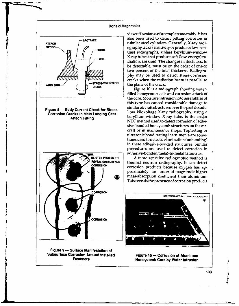
Donald Hagemaler
view of the status of a complete assembly. It hasalso been used to detect pitting corrosion in
ATTACH tubular steel cylinders. Generally, X-ray radi-FITTIN PROBography lacks sensitivity or produces low-con-
trast radiographs, unless beryllium-windowCOIL X-ray tubes that produce soft (low-energy) ra-
diation, are used. The changes in thickness, toPbe detectable, must be on the order of one-to
two percent of the total thickness. Radiogra-phy may be used to detect stress-corrosioncracks when the radiation beam is parallel to
-- STRESS-CORROSION the plane of the crack.CRAC Figure 10 is a radiograph showing water-
filled honeycomb cells and corrosion attack ofthe core. Moisture intrusion into assemblies ofthis type has caused considerable damage to
Figure 8 - Eddy Current Check for Stress- similar aircraft structures over the past decade.Corrosion Cracks in Main Landing Gear Low kilovoltage X-ray radiography, using a
Attach Fitting beryllium-window X-ray tube, is the majorNDT method used to detect corrosion of adhe-sive-bonded honeycomb structures on the air-craft or in maintenance shops. Taptesting orultrasonic bond testing instruments are some-times used to detect delamination (unbonding)in these adhesive-bonded structures. Similarprocedures are used to detect corrosion inadhesive-bonded metal-to-metal laminates.
3lSTER PROBED TO A more sensitive radiographic method isREVEAL SUBSURFACE thermal neutron radiography. It can detectCORROSION corrosion products because oxygen has ap-
proximately an order-of-magnitude-highermass-absorption coefficient than aluminum.This reveals the presence of corrosion products
INSPECTION METHOD: XRAY RADIOGRAPHY
Figure 9 - Surface Manifestation ofSubsurface Corrosion Around installed Figure 10 - Corrosion of Aluminum
Fasteners Honeycomb Core by Water Intrusion
193
PC

Second Annual International Conference on Aging Aircraft
as wellasmetal thinning. If moisture is present zontal stabilizer skin planks. The cracks runin the corrosion products, then the hydrogen fore and aft from the attachment holes in theatom adds additional absorption of the neu- integrally machined plate stock. The cracks aretron bearer, which provides additional contrast detected by directing the ultrasonic beam normalto the neuron radiograph. Two major obstacles to the crack plane. The inspection is performedare encountered in applying this technique: the from the external surface of the stabilizer centerstate-of-the-art practical thermal neutron sources box.are not portable and require long exposures be- Ultrasonic thickness gages are commonlycause of the low flux; and the presence of used for detection of exfoliation, stress-corro-hydrogen compounds such as trapped mois- sion cracks, and general material thinning. Pit-ture, fuel, or sealing materials, can mask the ting and intergranular corrosion cause scatter-corrosion products and reduce detectability. ing of the ultrasound and can be detected by
the use of shear waves in an angular incidence.Ultrasonic In addition, this scattering can result in attenu-
ation of longitudinal waves (straight beam)Ultrasonic testing provides a sensitive de- commonly referred to as loss of back surface
tection capability for corrosion damage when signal. This phenomenon serves as a means ofaccess is available to a surface having a con- corrosion detection in relatively thick struc-tinuous bulk of material exposed to the corro- tures. Its main limitation is that increased at-sion. Stress-corrosion cracks or exfoliation are tenuation may also be caused by sealants orexpressed by production of a new interface adhesives. Additionally, ultrasonics cannotwithin the material that causes reflections in a provide any information about layers furthershorter time period than reflections from the than the probed one unless they are properlyback surface. bonded.
As illustrated in Figure 11, ultrasonic test- The manual ultrasonic technique, for de-ing has been successfully used to detect stress tection of exfoliation corrosion, requires thecorrosion cracks in the 7075-T6aluminum hori- use of a liquid couplant on the surface of the
UPPER TYPICALSKIN ULTRASONICPANEL - INSPECTION
LOWER SKINAN PANEL
SCASCAN
TYPICAL CRACKTYPICAL CLOCATION ALLPAON T LOWER PANELSAUL UPPERLTYPICAL
ULTRASONIC
INSPECTION AREA
Figure 11 - Ultrasonic Detection of Stress Corrosion Cracks in HorizontalStabilizer Skin Planks
194

Donald Hagemaler
test part. Small diameter [6.35-mm(.25-inch)] reflection is obtained. This inspection techniquesearch units are employed to reveal small areas is very successful in detecting medium to largeof corrosion. The circle template may also be areas of corrosion but will not find smallerused to guide the search unit around the pe- areasthataredetectableusingtheeddycurrentriphery of the fastener head. Tests performed technique.at both 5 and 10 MHz yielded equally good re-sults. Theultrasonicdetectionoftheexfoliation Eddy Current Testingscorrosion is based on the principle of both ul-trasonic scattering and attenuation. When the To perform the high-frequency eddy cur-search unit (probe) is placed over an uncor- rent test, the instrument is calibrated using aroded areas, multiple back reflections (thick- known corroded sample. Typical eddy currentness values) are obtained as depicted in Figure response to exfoliation corrosion around in-12. However, when the probe is place over an stalled fasteners is shown in Figure 13. Thearea of exfoliation corrosion, no back surface phase angle on the impedance plane cathode
ray tube (CRT) is about 45 degrees at 20kHzand about 90 degrees at 50kHz. Hence, a morereliable inspection can be performed at thehigher frequency. The use of high-frequency(100 to 300kHz) pencilpoint probes and a circle
RESPONSE FROM UNPAINTED template is necessary in order to detect veryOR NORMAL PAINT small areas of corrosion. The circle template isTHICKNESS - NO CORROSION centered over each fastener and a 360-degree
scan is made with the eddy current probe. The
-2
I ] In I A i
PAO E ONI n'
(Al EDDY CURRENT RESPONSE, (8) EDDY CURRENT RESPONSERESPONSE FROM NO CORROSION FROM CORROSION USINGCORRODED AREA - LOSS 20-kHz. 1/2.IN.-DIAMETEROF BACK REFLECTION PROBE
2- EDDY CURRENT PRIIH L
t;] 1 -111 1 l l 1
(C) EDDY CURRENT RESPONSEFROM CORROSION USING50-kHz, 1/4-1N.-DIAMETERI l 1 ] l I PROBE c
Figure 13 - Eddy Current Impedance-PlaneFigure 12 - Contact Ultrasonic CRT Responses for Exfoliation Corrosion AroundResponse Fastener Holes In Wing Skins
195

Second Annual International Conference on Aging Aircraft
corrosion response will appear on theCRT and portion of the fuselage (bilge) is a notorious col-remain there until electronically erased. This lector of liquids and waste materials. Areasmethod is quite slow but has been shown to be around lavatories, galleys, and batteries areaccurate in the detection of very small areas of especially susceptible to corrosion. In this case,corrosion around installed fasteners. 6 moisture found its way into the crevice between
Eddy current testing (mainly low frequency) the titanium and aluminum, and galvanic cor-is being used to detect thickness changes, due rosion thinning occurred in the aluminum skin.to corrosion and cracks in multilayer struc- The thinning is not detectable from the outsidetures. The use of eddy current instrumentation the aircraft until it has eaten completely through.that indicates the amplitude and phase allowsdifferentiation of corrosion thinning from spac- Acoustic Emission Testinging of layers, liftoff, and cracking. The low-frequency eddy current technique has been Modem adhesive-bonded aircraft structuresuseful in detecting crevice or galvanic corro- are protected from corrosion by using baresion between aluminum skins and titanium (nonclad) aluminum, phosphoric or sulfuricdoublers. anodic layers on the substrates, corrosion-in-
Whenever there is a contiguous fraying hibiting primers over the anodic layers, non-surface t .:at can trap moisture between two perforated honeycomb core and sealants overdissimilar metals, a good possibility exists for exposed adhesive fillets or fraying surfaces.the generation of galvanic corrosion. In the Oldearbondedstructuresweremadeusingcladexample of Figure 14, a titanium doubler was materials, Forrest Products Laboratory (FPL)installed in the lower section of the fuselage etch of the substrates, no corrosion-inhibitingand adjacent to the aluminum skin. The lower primers, and perforated honeycomb core. These
conditions enhanced the possibility for crevicegalvanic corrosion attackbetween the adhesiveand the adherents.
To further enhance NDI detectability ofcorrosion and water in honeycomb structures,personnel at McClellan Air Force Base in Sacra-
.CORROSI mento, California developed the acoustic.XRPN emission method for this purpose.7 The test is
;I conducted by heating a local area of the structure-FF T.T and then placing an acoustic emission probeR R over the area and listening for emission caused
PRESENTATION A PRESENTATION BbCRT PRESENTATION FOR CRT PRESENTATION FOR by hydrogen gas or steam generated within
NO CORROSION SEVERE CORROSION (Figure 15). The test is conducted at about six-
inch intervals over the entire structure. Reports-. PROBE pindicate that the acoustic emission technique is
K A -MINUM-SKIN capable of detecting both gross corrosion and, j-- I1., corrosion initiation that is not detectable by
FAIR CROI other NDT methods. The method does giveoRO TITANIUM OUBLER some false calls at times but is still considered
R -the primary inspection method for checkingPRESENTATION C <4' honeycomb structures at McClellan AFB.
METHOD FOR DETERMINING
DEPTH OF CORROSION
Corrosion Summary
Major concerns associated with corrosion,Figure 14 - Impedance Plane CRT a destructive and costly enemy ofaircraft dura-
Presentations for Corrosion Thinning bility, are that it is extremely difficult to predict,
196
IL

Donald Hagemaler
cracks and general material thinning.__Eddy current testing (mainly low-frequency)
is being used to detect thinning due to cor-rosion and cracks in multilayered struc-
AC--ZTIC E.tSM MNO fr tures. High-frequency eddy current is mostappropriate for detection of stress-corro-
X-Y REcoRXR- sion cracks.SEARCH UI Acoustic emission testing (employing heat-
-- SPECIMEN generated emissions) has been used to de-tect corrosion and moisture in adhesive-
PR-AMPIFR-" bonded metal honeycomb structures.
Although the above NDT methods havebeen used successfully to detect corrosion, with
_respect to the type of corrosion they can detect,they are not equal in the following areas:
Figure 15 - Acoustic Emission Detection of 0 equipmentWater Intrusion into Adhesive-Bonded * sizeHoneycomb and Corroded Laminates * mobility or availability
* cost of performing the testto prevent, and to detect early in its formation. I availability of the test method to the operatorAccess to corroding areas is frequently limitedor impossible due to intervening structure. These test method factors are rated in FigureTherefore, conventional NDT techniques are 16. Visual inspection is the primary corrosion-often used to detect such corrosion and elimi- detection method. Non-destructive inspectionnate the costly and potentially destructive dis- is generally not used until corrosion has beenassembly involved, detected during routine maintenance of the
When the inspected area is physically aircraft. Therefore, it is applied after the fact toaccessible, visual inspection is commonly used similar structures on other aircraft in the fleet.for corrosion detection. Sometimes, tools suchas magnifying glasses or borescopes are used Gaps in Present Technologyfor evaluation of less accessible areas. These in-spections involve a search for change of color, Because NDI is an important part of aircrafttexture, corrosion products, bulges, or cracks. maintenance programs, it must continually be
In the case of hidden corrosion, several improved to meet the challenges and demandsNDT methods can be used: X-ray or thermal of the industry. A few gaps still exist in theneutron radiography, ultrasonic, eddy currnt current technology:or acoustic emission.
* Specific NDI methods are used for each* Radiography is generally used for its ad- case of corrosion, based on:
vantage in inspecting complex structures -Type of corrosionand revealing an overview of the status of -Site of corrosion on aircrafta complete assembly. -Access to corroded area
* Ultrasonic testing provides a sensitive de- -NDI techniques available to operatortection capability for corrosion damage when -Severity of corrosionaccess is available to a surface with a con- o Corrosion initiation or small areas of corro-tinuous bulk of material exposed to the sion are difficult to detectcorrosion. Ultrasonic inspection is commonly e Most NDI technicians have not been trainedused to detect exfoliation, stress-corrosion in corrosion detection
197

Second Annual International Conference on Aging Aircraft
DETECTION EQUIPMENT
METHODS SIZE J MOBILITY AUTOMATED SPEED COST AVAILABILITY
VISUAL SMALL GOOD NO FAST LOW YES
TAP TEST A % SMALL GOOD POSSIBLE FAST LOW YES
ULTRASONIC A. MEDIUM GOOD POSSIBLE MODERATE MODERATE YES
SMALL GOOD POSSIBLE MODERATE MODERATE YESEDDY CURRENT TO
MEDIUM
XRAY MEDIUM FAIR NO SLOW HIGH MOST SHOPS
RADIOGRAPHY TOLARGE
NEUTRON LARGE POOR NO SLOW VERY RARERADIOGRAPHY I HIGH
'ACOUSTIC ( MEDIUM FAIR NO MODERATE MODERATE VERY FEW SHOPS
WITH HEA T
*PARTS MUST BE REMOVED FROM AIRCRAFT FOR TEST
Figure 16 - Rating of Test Methods
Many NDE engineers are not familiar with 3. D.J. Hagemaier, Reliable Supplementalcorrosion-detection methods or techni, ues. Inspections of Aging Commercial Aircraft,
Douglas Paper 7954, Douglas AircraftImprovements must be made in the above Company, Long Beach, California, (1987).
items to advance the state-of-the-art NDI tech- 4. D.J. Hagemaier, P. Abelkis, and M. Har-nology concerning corrosion detection. mon, Supplemental Inspection of Aging
Aircraft, Materials Evaluation, Vol. 44, No.8, July 19, 1986.
References 5. D.J. Hagemaier, Application of Eddy Cur-rent Impedance Plane Testing, Materials
1. W. Rummel, et. al: Characterization of Struc- Evaluation, Vol. 42, No. 8, July 1984.tural Assessment Testing. SA-ALC/MMEI- 6. D.J. Hagemaier, Nondestructive Detection1/86, Kelly Air Force Base, San Antonio, of Exfoliation Corrosion Around FastenerTexas, (1986). Holes in Aluminum Wing Skins, Materials
2. R. Bessmer, et. al: Exploratory Develop- Evaluation, Vol. 40, No. 6, (1982).ment of Advanced Surface Flaw Detection 7. J. Rodgers, Acoustics Emission in AircraftMethods, AFWAL-TR-4121, AFML, Wright- Structural Integrity in Maintenance Pro-Patterson Air Force Base, Ohio, (1984). grams, Journal Acoustics Society, Vol. 1,
No. 2, (1982).
198

ATA/NDT Forum
JAMES L. MORGAN
Manager, Inspection /NDTTrans World Airlines
Good afternoon. It is an honor for me to The 31st ATA/NDT forum was held lastspeak before you this afternoon. August in Minneapolis. In attendance were
I am a member of the Air Transport Asso- over 340 people representing a variety of disci-ciation Task Force on Non-DestructiveTesting. plines involving NDT activities. Representa-This task force has had a number of responsi- tives from 21 U.S. and Canadian airlines and 36bilities over the years. The primary responsibil- foreign carriers attended the latest forum. Inity of this group has been to conduct an annual addition to conducting this annual forum, theATA/NDT forum. ATA Task Force has also been involved in
The purpose of this forum is to foster corn- many other endeavors. Among them are themunication and cooperation on technical and creation of safety standards to be observed bypractical aspects of NDT within the airline airline radiographers; the establishment of abusiness. The first forum was held in Kansas data file of the NDT equipment and a list ofCity in June of 1957. In attendance were 36 airframes and power plants used by each air-representatives from 14 U.S. airlines and seven line represented at the meetings. We have as-manufacturers. sisted in establishing the Spec 100 format of
At the first meeting the group was interested vendor produced NDT manuals covering theirin exchanging ideas and information between product. We have given assistance to the FAAthe airlines, and other interested organizations, flight standards service in the development ofon X-ray methods for inspecting aircraft. By advisory circulars relating to NDT practices.1958, two foreign carriers, Air France and SAS, Committee members have served as represen-also attended the meetings as well as represen- tatives on various national and technical com-tatives of the then newly organized FAA. The mittees and have provided reports on thesefirst mention of ultrasonic and eddy current functions at the regular ATA/NDT meetings.inspection methods appeared on the 1958 Examples of these include the American Soci-agenda. ety for Testing Materials, American Society for
J
199
Second Annual International Conference on Aging Aircraft
Nondestructive Testing, and American National and the human factors will enter here. Is theStandards Institute. instrument user friendly?
Now, as in the past, the forum functions to How complex is the application? To be ef-present common problems and stimulate dis- fective, our instructions must be very clear.cussion among the members and manufactur- What supplemental equipment may be needed?ers as to ways to solve these problems. Just this There is usually a test standard involved. Wepast August, at the forum, the Boeing Company need to consider the certification of the testrepresentative presented papers on inspection standard. There is a project in one of our ATAof lap seams. This is an important and a very committees right now to consider this and howinteresting subject to all air carriers. Many to approach it with the manufacturers, and thequestions were asked and many answers were vendors who sometimes manufacture test stan-given on that subject. And, as Mr. Hagemaier dards for us.demonstrated, the same type of discussion that What are the inspector's qualifications? Ishe just gave you is offered by representatives at he experienced? Is he certified? Are his work-the ATA forum. ing conditions comfortable? Procedures may
Another subject that is of great interest to be written without first being tried in the realme is what it really takes just to go out and do world, only to find that we provided access, butan inspection. The manufacturers give us meth- we can't get to it and the procedure doesn'tods of doing it, but what are all the different work.things involved? These are all important considerations, and
Among these I would list things such as the they're all within the context of the ATA /NDTtechnique. The technique to do the job is de- forum.pendent on the focus of the inspection. By focus It is in this framework of the ATA that anI mean the direction of the inspection or the Airline Inspection Task Force was formed. Ourintent of the inspection or the orientation of the latest project has been to develop the curricu-inspection.Whattypeofaflawisit?Isitacrack lum for the in-house training of NDT inspec-or is it corrosion or is it a void? tors. Once adopted by the carriers it will serve
Where is the flaw? Once again we have to to standardize the NDT training program byconsider the orientation of the inspection. specifying the minimum class content and train-
How accessibile is it? How much opening ing manhours.up is required. This is a consideration any time Last January the task force received formalyou have an aircraft out of service. Do you have approval to proceed with this project. A draftthe time to do it on the subject maintenance copy of this document was submitted to thevisit? operators in April. They indicated their ap-
What sensitivity is required? This requires proval, with minor changes. The final versioninformation from the stress people-they usu- of this document is nearly complete for distri-ally determine what the lead crack is and the bution as an ATA specification, ATA Spec 105.propagation mode and this determines our This is the recommended guideline for traininginspections. and qualifying personnel in nondestructive
We must consider logistics in the equip- testing methods.ment decisions. Can I afford a new Whizzit? This guideline will be available for eachWell, if I've decided I can and I've bought one, airline to use in the formulation of their trainingI might find that I have this nice piece of equip- program for qualifying NDT inspectors.ment, but I don't have the people trained in all An interesting finding during our discus-of the places that I need to use it. Equipment sions formulating these guidelines is the differ-sensitivity is continuing to grow with each ence in management systems within which wechange and state-of-the-art improvement that must operate to accomplish the same thing.we get. Each airline has a different labor contract rela-
Flaw detectability goes along with the sen- tionship or there may be no contract at all.sitivity required. The condition of the material Those with no contracts are free to develop
200

James L. Morgan
specialty groups which management can con- Included in any talk of NDT inspectiontrol, and provide training and utilize people should be a "wish list." I would like to see anywhere needed. new system to be reliable and cost effective.
Another airline may have a labor contract Give us improved detection with computerwhich allows little or no management control enhancement; and reduce the incidence of falseover who is selected. This system would suffer finds - the bane of all NDT inspectors. Tofrom many defects, including having to con- make a first-find crack inspection with a rapid,stantly train newpeople. Seniority is nota good large area inspection system would be the ulti-criteria for the selection, training and qualifica- mate tool, but it seems to be contrary to all thattion of NDT personnel. However, with the use is in existence today. A first-find crack wouldof this document, Spec 105, a program can be be at the onset of the cracking problem, whichset up to be compatible with any management would mean you are looking for a very smallsituation. It will provide a tool for the airline to crack. All of our systems for detecting smallimplement their in-house program for the most cracks inspect a very small area with each scan.efficient, effective inspector training by using The large area scan is used where you arethe same technical terms and equipment that is looking for a large defect.in use by the group that he will be working in. The ATA/NDT forum has served well toIt will be the most cost effective, due to the help the airlines stay abreast of the needs andflexibility with which the training is available issues in our industry. Airlines share a com-to the inspector. mon problem, aging aircraft. This phenome-
The requirements of our inspections are non will not just go away. Its demand ondetermined by the aircraft. The methods we maintenance and inspection functions willuse to do the requirements are determined by continue and increase. Nondestructive testingthe manufacturer. There are optional ways to shares this problem. It's the lion's share. It'sinspect, but the procedure is determined by the this share that is causing the rapid change inmanufacturer. There are also mandatory in- the NDT operation. It is evolving from a some-spections, which experience has shown should times used tool, to a continuing series of man-be thoroughly understood and followed, dated or mandatory NDT inspections. Each of
The methods of NDT inspection are many, these inspections require a greater and greaterthere are tried and true techniques. There is a degree of expertise and more and more man-need for innovation in these fields to aid in hours of inspection.maintaining and extending the air worthiness The demands placed on NDT inspectors asof the nation's aircraft. I have spoken about the a result of this increased work load call for theresult of the inspection being dependent on the best possible training and equipment to ensureaccurate statement of the inspection proce- they have the best technical skill and equip-dure, the training and qualification of inspec- ment to accomplish his job.tion personnel and the equipment and facilitiesneeded.
201

NDT Evaluation
BRUCE A. KOTZIAN
FAA Aviation Safety Inspector - Maintenance
Good afternoon. Yesterday morning Mr. down with the inspectors on each shift andRamakisaddressedthisconferenceonongoing query their observations on NDT proceduresaircraft maintenance evaluation by the FAA. and training. We also review the operator'sPart of the evaluation is to examine the opera- NDT equipment to see if it meets today's de-tor's nondestructive testing program. I'vebeen mands, plus we are interested in what stepsasked to give a thumbnail sketch of what areas have been taken to have state-of-the-art equip-of nondestructive testing (NDT) are being ment to meet the future needs of aging aircraftevaluated. inspection.
Each evaluation team spends about two All this data that we' re acquiring is enteredweeks performing the evaluation at each of the into our computer program along with otheroperators. The first week isspent reviewing the aging aircraft evaluations. And as Stephen Bobopaperwork. We take a look at the NDT manu- discussed, we're on the 11th aircraft and we'realsand theircontents. Weexaminework proce- going up to 90.dures by reviewing the work cards and NDT What are our observations so far? We havetechniques used by the operator. We evaluate found some operators using some antiquatedthe manufacturer's service bulletin, matching equipment even though they have the state-of-that against the techniques used by the air the-art equipment on hand. In many cases thecarrier and we review the operator's training NDT section is not separate from the qualityprograms, classroom training, on-the-job-train- control department, which presents traininging and the experience of the NDT inspector, problems for the operator. The lack of stan-
Thesecond week weevaluate theaircraft in dardization between the manufacturer's serv-its heavy maintenance "D" check. We evaluate icebulletin presents a problem for the operator.the NDT inspector performing the actual in- Most operators seem to have a difficult time inspection on the aircraft, on all shifts. We sit purchasing state-of-the-art NDT equipment and
202

Bruce A. Kotzlan
there isn't any standardization in the training to look at approximately 90 aircraft total. Weprograms between operator to operator nor to hope to have a good idea on how the operatorthe manufacturer. performs nondestructive testing. We will look
In summary, as I said earlier, there are 11 at the problems that he faces and help himaircraft that have been evaluated, and we plan solve them.
203=..

Session V: Human Factors
CHAIRMAN WILLIAM T. SHEPHERD, PH.D.
Manager, FAA Biomedical and Behavioral Science Branch
When we were asked to take part in the way of presenting a service bulletin? What areAging Aircraft R & D program, we thought this good ways of writing work cards?would be a pretty tall order. We have done a We want to provide a sort of menu or selec-fair amount of work on air traffic control prob- tion of things that would be useful to a widelems and we had to grapple with just what it is audience. We would like to talk about thingswe could do, what we could produce for this like trainingandselection of maintenance tech-program. nicians and inspectors. We want to deal with
After some debate we decided the best questions related to the work environment.thing we could do would be to provide infor- What constitutes a good one and what are badmation. That is essentially what we aregoing to things to have in your work environment?do for the next couple of years. We are going to Equipment, maintenance equipment, jobprovide information that will be useful to de- performance aids - there are all sorts of newsigners, manufacturers, and, included in that technology coming on the scene now and weof course, would be the people who deal with would like to be able to describe that. Alsothings like maintainability, worthy of scrutiny are inspection methods,
We want to try and help the air carriers and human limits and physiology, vision, color0 their maintenance operations including, repair vision, vigilance, boredom and complacency.
stations and not the least of which - the FAA. Those topics that are very prominent and haveWe want to providea compendium of informa- been shown to be important in recent years.tion and we'll call it a handbook for now. We havealready started our research activ-
We may end up with things like video ity. One of our speakers this morning will telltapes and other forms of media. But what we you a little about some of the work alreadywant to do initially is provide information done at Pan Am at JFK.dealing with such topics as information trans- We send our people on aging fleet evalu-fer. How do you write an AD? What's a good ation visits. So far we have been to United, Pan
204
William T. Shepherd
Am and Aloha. We have been to Henson at conference. We held a kickoff conference lastSalisbury, TWA at Kansas City and Tramco, a year. We used it to scope the problem and torepair station in Everett, Washington. There calibrate things for ourselves, and in that con-are many more site visits planned and we ference we identified a number of topics thatintend to have more of our people on each one were more prominent than others.of these. Among them as I mentioned earlier, are
The intention is to try and gather as much information transfer and training. Now we aredata and information as we can related to planning another conference for December 1989.human factors aspects of the maintenance in- We are going to dedicate that conference to thespection business. We have some of our people one topic of information transfer.from CAMI, the Civil Aviation Medical Insti- We hope to deal with a whole spectrum oftute in Oklahoma City, managing this particu- issues. We are in the process now of formulat-lar task. ing our speaker list and we would be happy to
We are also looking at human factors asso- take any suggestions on that too. What I wouldciated with nondestructive inspection, human like to ask any of you who would be intereJ. iengineering of equipment and training issues. in providing us some input, is make your
What we want to do is to get as much input wishes known to me.as we can to our program. Since we are hope- We want to get information from air carri-fully providing useful information we really ers, training organizations, people who are inneed to get a lot of this from the user commu- the business of training A & P mechanics andnity, that is, the industry, the training organizations within air carriers.
By all means, feel free to communicate with We also would like to talk with NASA andus on things you think are important to this DOD representatives since they may have someeffort. Our ultimate product is going to be an special expertise that may be applicable to theinformation compendium covering all those civil side. And of course, we want to talk to thetopics I mentioned earlier plus others, too. academic community. We intend to have our
We have already held one human factors next human factors conference in June 1990.
205

The Vigilance Phenomenon
EARL L. WIENER, PH.D.
Professor of Management Science
University of Miami, Florida
I'd like to talk to you today about a basic probability of detection started to drop to abouthuman factors phenomenon, the vigilance half of what it was under alerted conditions,phenomenon and the problems when we ap- and continued to drop throughout the flight.ply that to the inspection of one kind or another. Let me outline what I am going to cover
The vigilance story has an interesting his- today. In the basic vigilance process, I'll talktory, which I'll briefly give you. During WW II about how it is applied to inspection and whatwhen the RAF was flying long missions over the problems of the inspector may be, and thenthe Bay of Biscay on anti-submarine patrols look ahead into the future.hoping to catch a surfaced submarine, it was These are the elements of a vigilance task.noticed that the radar operator seemed to be First, the signals are subtle. By the signal Ithe last one to see the target on the radar scope. mean whatever it is the person is looking for, be
Someone else would walk past the radar it a crack in a component of an aircraft or ascope, bend over and say, "How about that one defect in a manufactured good or a surfacedright there?" The radar operator would say, submarine showing on radar - that's a signal."Oh, yes! I never saw it." So it looked as if the A vigilance task looks at signals that areperson most qualified and in the best position subtle. They have a low signal-to-noise ratioto spot the radar target on these long, monoto- and often they are evanescent, that is, they maynous patrols was the one least likely to do so. appear and then disappear rapidly and theThe problem was taken into the laboratory and vigilant inspector has to catch it while he can.this was the beginning of the scientific study of There are a class of signals which expandhuman vigilance or watchkeeping, and it was and become more conspicuous over time. I amfound that the decay curve for alertness was thinking of something like a radiologist look-very rapid, far more rapid than anyone had ingatan expanding tumor. That is, month afterever thought. month he may x-ray a patient and the target in
In a matter of less than half-an-hour the this case would be a tumor which is getting
206

Earl L. Wiener
more and more conspicuous as time goes on. has ever been done. We can duplicate the radarBut for the most part in your industry, we're operator and his loss of vigilance in the labora-talking about flaws which are fairly constant, tory very easily. We see from the first to thealthough I suppose one could argue that a second twelve minute period a drop from 70 orcrack might open up and become more con- 75 or so percent down into the 60 percent rangespicuous over time. and then it continues and levels off. Sometimes
The second feature of the vigilance task is one sees an upswing in the last period of thelow signal rate. That is, low probability events, experiment.Namely, the lower the probability of the event, Figure 2 was an experiment in which subjectsthe lower the probability of detecting it. were trained the first day by various training
The final feature is that the events occur methods and then on the second day, labeledwith temporal uncertainty - they are random Day Two, they ran under the most sparsein time. One cannot predict the appearance of condition with no training aids available. Youone of these events and, furthermore, they are see the slight increase in performance, whichindependent of previous events. That is, after was realized with an investment of only a 48-you see one of these events it is no more or no minute run.less likely that another event will occur in any In general, with vigilance and inspectionspecified interval following this. tasks, practice alone does not improve per-
Figure 1 shows the typical vigilance func- formance. But one can find training methodstion, the decline of vigilance or probability of that are effective in increasing the performancedetection over time. The time period in this level, that is, the probability of detection. Merelyparticular experiment was only 48 minutes and practicing the task, continuing to do it over andthe decline in the probability of detection is over does not lead to an improvement in per-apparent. formance. But there are methods that can be
This is the so-called vigilance decrement applied that will increase the probability ofand it appears in almost every experiment that detection of the signals.
The signal rate effect in Figure 2 and theparameter of those 16, 32 and 48 curves, werethe number of signals that were introducedduring the 48-minute experimental run. You
so could think of that as the number of defects thatwould appear as the person did an inspectiontask over a 48-minute period.
The larger the number of defects, (the poorerthe quality of the product) the higher the proba-
S70 bility of detection. This is one result that hasheld up for years from one experiment to thenext. It is almost irrefutable in its constancy anda conclusion one might draw is that a higher
4quality product will lead to the worst inspec-tion. When the probability of a defect being
0 |Y: present is low, the probability of finding it willbe low.
Figure 3 shows more data from the real
3 4 world of inspection. This vigilance curve is onerme Blocks that I produced a number of years ago by cre-
ating a computer driven adaptive vigilancetask such that the size of the signal increased ifthe inspector missed and decreased if he caught
Figure 1 the signal.
207

Second Annual International Conference on Aging Aircraft
__-9o._ _ _ _ _ _ _ _ _ _ _ _ _ _ _ _ _ _
0%
Bo- DAY I DAY 2
4)70-4\\
o. -.-O N
332
3 4"| 2 3 4
12 Minute Blocks
Figure 2
Therefore, the size of the signal was con- the point being that the human inspector istinually adapting according to his proficiency, influenced by the environment, physical andset for a target detection rate of 75 percent. If he social, in which he operates. He is not operatingfell below 75 percent, the gap opened up, so to in a physical or social vacuum. He is influencedspeak. And, if he overperformed by detecting by economic conditions. He is influenced bybetter than the target of 75 percent, the task got social conditions, including peerpressure fromharder. So it got harder or easier depending on his fellow workers and managerial pressure ashis level of performance, and asyou can see this well, often managerial pressure to pass goodsis the width (w). The curve is drawn upside rather than to reject them.down to make it look like a typical vigilance He is also affected by standards, specifica-curve. As before, 32 signals were presented in tions, training, experience and the payoff to48 minutes, and the width of the signal neces- him is the cost of the two types of errors hesary to lead to a 75 percent detection rate, in- could make. Figure 4 is a typical decision pay-creased, a new definition of vigilance decrement. off matrix.
The application to your area is that if you When there are only two choices, the in-want a constant probability of detection, you spector can accept or reject an item and therecan expect that over time the vigilance rate, the are two possible conditions of the item. Thesize of the signal (defect or flaw) one looks for, product can either be effective - good, ormust increase. If you are looking for constant defective - poor. One can then cast this into asize signals, as before, the probability of detec- two-by-two decision matrix.tion will decrease. If the product is good and he accepts it, that
Let us focus on the human inspector with is a correct decision. If it is defective and he
208

Earl L. Wiener
300
310 - 60 POINTS 1 INCH
Z 320V)
0330
' ,- 340-"
350 _ 1 1 1 - 1 1 -l I
2 8 16 24 32SIGNAL NUMBER
Figure 3 - Airframe Structural Integrity Program
rejects it, that is correct. But let us focus for now Two Errors. They carry with them a price, Vad,on the two erroneous decisions that can be which would be the value or cost of acceptingmade. a defective item.
One erroneous decision is that the product What the inspector must do is balance theis effective but he rejects it. That is called a Type cost of those two errors. One cannot eliminateOne Error. That carries a price, Vre, thevalueor those errors altogether but one tries to mini-cost of a false rejection. mize the total cost of those two items. Let me
The cost would be acceptable goods that give you a few examples of detection rates fromhave been rejected and carry the price of rein- real world inspection tasks published in the in-spection or scrapping something that is good spection literature and I ask you to focus on the-all the work that would be involved in either last column in Figure 5. These are typical in-reclaiming or replacing rejected goods that spections where the goods are reinspected andshould not have been rejected. the rate of rejection can be found. The percent-
Perhaps far more serious would be another age of detection is alarmingly low.comer of the two-by-two matrix and that is These are real world, not experimental,when defective goods that are passed on, Type data. You see detection rates as low as 30
209

Second Annual International Conference on Aging Aircraft
PRODUCT PRODUCT
EFFECTIVE DEFECTIVE
TYPE IIERROR
CORRECTA P ACCEPTANCE
0 Vad
oJr TYPE IERROR CORRECT
REJECTCREJC REJECTIONVre
Figure 4 - Decision Payoff Matrix
AUTHOR DATE PRODUCT % DETECTED
Jacobson 1952 Solder joints 83
McCornack 1961 Various 30-91
Chaney/Teal 1967 Machine parts 30-50
Sheehan/Drury 1971 Metal hooks 57-80
Fox 1964 Metal coins 55
Jamieson 1966 Telephone equip. 41-70
Rigby/Swain 1975 Various 30-90
Figure 5 - Examples of Accuracy in Inspection Tasks
210

Earl L. Wiener
percent there. The average is somewhere around can change the nature of the task and perhaps60 percent. In other words, an awful lot of give better inspection tools and training asgoods are going through. well.
Figure 6 does not show the false rejection I want to point out that there are ergonomicrate, those cases where good, acceptable, effec- methods that can be used to overcome thistive goods are rejected. There can be more than problem. But it cannot be overcome by select-two states. It is possible to classify product into ing better workers. That has not been proven tok states, yielding a k-by-k decision matrix, be effective at all. In fact, there is a kind of a
Figure 7 are data from 39,000 inspections of reverse thought there. It has often been felt thata small metal hook. This is a relatively high the low end of the intelligence scale in the workquality product; 98 percent of the hooks were force might be the best inspectors: dull peopleeffective and two percent were defective. About for dull jobs, but that has not been proven to befour out of five of the defectives were detected the case at all.here and rejected; and about a fifth passed the I have reviewed the literature on selectioninspection and became Type One errors. of inspectors in a chapter in Dr. Drury's book.
So, in summary, I'd like to say that the Attempts to improve inspection performancevigilance problem is severe, it's built into the by going out and selecting the right people tohuman. It is difficult for the human to maintain do the job have not proven to be effective at all.alertness over time, and that time period is far So I would put my money into ergonomicless than an hour, really more like half an hour, improvement, job redesign, better tools andin which one would see a significant decline better training; and, not be led into the trap thatfrom an alerted condition to a far diminished there are some good guys out there, if youperformance curve, could only find them, test them and bring them
There are things that we can do about it. We in.
QUALITY 1 QUALITY 2 QUALITY 3 QUALITY 4 QUALITY 5
zo V 1.1 V1.2 V1.3 V1.4 V1.5
I V 2.1 V2.2 OVER-RATED
Co,
V 3.1 V3.2 V3.3 V3.4 V3.5
0 UNDER-RATED V4.4 V4.5
a-U) V5.1 V5.2 V5.3 V5.4 V5.5
Figure 6 - Utility Matrix for K-States
211

Second Annual International Conference on Aging Aircraft
DATA FROM 39,000 INSPECTIONS
INSPECTOR'S PRODUCT PRODUCT
ACTION DEFECTIVE EFFECTIVE
ACCEPT 134 (.0034) 38,195 (.9793) 3329 (.9828)
REJECT 646 (.0166) 25 (.0006) 671 (.0172)
TOTAL 780 (.0200) 38,220 (.9800) 39,000 (1.0)
Figure 7
212

Industrial Inspection
COLIN G. DRURY, PH.D.
The Center for Industrial EffectivenessState University of New York, Buffalo
I am going Lo talk about inspection, particu- can inspect better, how you save money bylarly industrial tasks, so I am beginning where doing good human factors work. Then I'll talkEarl Wiener ended. about what we can change and what we can't
He showed how a human being does an change and, finally, how we proceed frominspection job, starting off with laboratory data here-my views, not necessarily the official viewsand then moving to field data from inspection of the FAA.situations in factories. I am going to start straight The challenge is to take a typical aircraftout with inspection data from factories. Almost inspection situation and find out how to do itall the data I have is from actual plants that we better. We are just starting task analysis ofhave worked in. This is not laboratory oriented inspections. We are visiting inspection andwork. maintenance sites to analyze how the job is
For many years we have studied human being done as a starting point for how we canfactors inspection and quality control in manu- help people do it better.facturing industry. The challenge is to apply it You can treat inspection as a single task orto the industry of aviation inspection, aviation take it apart into its components. I am going tomaintenance. break them down a bit using simple task analy-
The human as a technical system is what I sis or task description of an inspection job.want to emphasize first. We know a lot about A part comes to the inspector who, first ofthe human as a mechanical, cognitive system, all, searches to find if there is anything therea system you can put numbers onto and get that iq of interest. The search can either bedata from to find out how to do things better visual, (and I will concentrate on visual searchand how to optimize. Next, I want to give you today, because it is an area you can quantifysome case studies from manufacturing. I have and it is still the cornerstone of lot of lot of ourchosen a couple which have shown how you inspection) or it can be NDI or any other proce-
213-K

Second Annual International Conference on Aging Aircraft
dure we are using for searching. Once thesearch procedure has found something calledthe flaw, something which is interesting - itmay or may not be a fault - you then have todecide. Is it a good item? Is it a bad item? Is this Ifault too severe? Is it not severe enough? Youhave to compare it against standards.
So there is a search task, a decision task and N ,, C
then disposal of the item. In industry this means E :oHput it on the conveyor, put it in a different box.In aviation inspection it means write it up ortake some other action.
This can be visualized as a model ratherthan a list. (Figure 1) An item comes to theinspector, who, if it is a visual task, fixates a '0
small area. The inspector can only fixate a small ._part of this area because it is impossible to seeeverything in one glance. LA
If they find a flaw in it then they go into the LESdecision making box in Figure 1. If they do notfind a flaw in it then they go around and fixateanother small area and continue the searchprocess. If they find a flaw they get down into LIIIIthe flaw rejectable box and then decide whetherto accept or reject the item.
But if there is no rejection, if the flaw seen isnot sufficient to cause rejection, then they haveto decide whether it is worth continuing to Figure 1look. From Figure 2, the inspector decideswhether there is time left to continue searching.Whether management or the inspector makes reach the accept box, you must do two things inthis decision, a decision will eventually be made. parallel. Either the search can fail to find aThe inspector will eventually have to call this defect, or when the defect is found, you cangood item good. The point about this model is come to the wrong decision. So it is hardlythat it says the only reason you ever accept surprising that there are a lot more errors insomething is that you cannot spend more time terms of missing signals than there are in termsto look any further for defects. The truth is that of false alarms because one of them is a serialthe only reason we accept anything is that we process and the other one is a parallel process.have decided that it is no longer wortn searching. This model begins to explain some of the data
From Figure 1, we can derive some conse- that Earl Wiener discussed about why you tendquences. First, if the item is in fact good, then to to get more missed defects than false alarms.get down to the reject box, you have to do two We have seen that there are search andthings in series. You have to find a flaw that is decision making in this simple task analysis.not really a flaw, which means the search proc- Those are the two error prone parts of an in-ess has to fail. And, you have to call the flaw a spection job and we have to examine them afault, which it really is not, which means the little more deeply to find out something aboutdecision process has to fail. Hence, if you want them.to make a Type One Error of a false alarm, you Search can be visual, which I have talkedhave to make two errors in series. about already. It could well be procedural as
However, if the item is in fact faulty, then to when you are searching lower rivets with an
214

Colin G. Drury
NDI device to detect any cracks. That would be you are looking for, the lighting, the contrasta procedural search rather than a visual search. and many other factors. We can do the same
A decision to make is where you compare thing for decision making tasks. Here we ex-an indication to standards. You compare a blip amine a flaw to see whether it is better or worseor a trace on your machine against a standard than standard. The standard may well be heldthat you stored in your head ora standard that in memory, which brings in another fallibleyou have physically used to calibrate the ma- human information processing component.chine. Almost all of the components of the human
We thus have a model of the inspection being are fallible, as are almost all of the compo-process we can work with, a model which nents of machines. In human factors engineer-works just as well with pure manual inspection ing we are doing just as we do with any otheras it works with machine-aided inspection, human endeavor--trying to build an infallibleThe same thing applies equally well to totally system with fallible components.machine inspected inspection. There is still a Earl Weiner has discussed signal to noisesearch portion and a decision portion. If you concepts. A fault is a signal, a non-fault is noisehave ever analyzed the literature on, for ex- and the Type One and Type Two Errors tradeample, printed circuit board inspection using off against each other so that as you get more ofpurely automated devices, you can find exact one you tend to get less of the other. Decision isparallels between what I am saying about the what is called a data limited task. Usually, thehuman and what is going on in the machine, time taken to make the decision is fairly short.
Letusexamineinmoredetailoneofthetwo The inspector either comes to one decisionerror prone stages: visual search. Figure 3 shows quickly or comes to the other decision quickly.an example of an industrial task where a per- Looking at the fault for longer usually does notson is searching for a bad solder joint. It is very allow you to make a better decision, hence it isdifficult to tell when you have a good joint and data limited. The data or the signal to noisewhen you have a faulty one. The inspector ratio of the data coming in is typically poor,pe >-rms a search task of this sort by having an causing problems of decision accuracy.area in which the fault can be seen, a small area To give you an example of a decision task,around the line of sight which is called the Figure 3 shows some work we have done onvisual lobe. Within this visual lobe, you can see printed circuit board inspection where youa defect. Outside this visual lobe, you cannot compareagoodboardagainsta faulty board orsee it. The inspector searches the item by moving potentially faulty board and the display givesthis visual lobe successively to different por- you both of them together so that the inspectortions of the visual field. Some obvious conse- can do a direct comparison. You can make aquences of this are if you have a fixed size of comparative judgment of whether an item isvisual lobe then the longer you spend search- faulty, rather than an absolute judgment, whiching the more coverage you get and the greater is much more error prone. In decision tasksyour probability of detecting a fault. such as this, the two errors trade off against
Thus, something as simple as how long each other.you give a person to do a task, is very impor- Figure 4 plots the two inspection outcomestant in visual search tasks. Search is what is against each other. Each point represents onecalled a resource limited task It uses the human of seven human inspectors in an experiment inresource of searching and the more resources the glass industry. The inspector whose pointyou can put in it, the better. You can tell re- liesattheupperendofthecurvefindsabout80source limited tasks because the longer you percent of the defects but only accepts about 50give a person to do them the better job they do. percent of the good items. The person whoseFigure 2 gives an example. You can see a defect point is at the bottom right finds 95 percent ofclearly within a certain area and outside that the good items (so he does not make many falsearea you cannot. The actual size of the visual alarms) but, he only finds 30 percent of thelobe of course depends on the size of the defect defects. Neither performance is particularly
215

Second Annual International Conference on Aging Aircraft
Figure 2
Figure 3
216
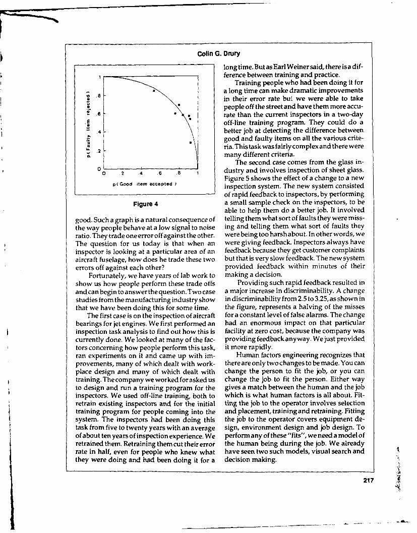
Colin G. Drury
long time. But as Earl Weiner said, there is a dif-1 ference between training and practice.
Training people who had been doing it for
.8 a long time can make dramatic improvementsin their error rate but we were able to takepeople off the street and have them more accu-rate than the current inspectors in a two-day
E0 off-line training program. They could do a4 better job at detecting the difference between
*good and faulty items on all the various crite-ria. This task was fairly complex and there were
C. many different criteria.The second case comes from the glass in-
0 .2 .4 .6 .8 1 dustry and involves inspection of sheet glass.Figure 5 shows the effect of a change to a new
p( Good item accepted )inspection system. The new system consisted
of rapid feedback to inspectors, by performingFigure 4 a small sample check on the inspectors, to be
able to help them do a better job. It involvedgood. Such a graph is a natural consequence of telling them what sort of faults they were miss-the way people behave at a low signal to noise ing and telling them what sort of faults theyratio. They trade one error off against the other. were being too harsh about. In other words, weThe question for us today is that when an were giving feedback. Inspectors always haveinspector is looking at a particular area of an feedback because they get customer complaintsaircraft fuselage, how does he trade these two but that is very slow feedback. The new systemerrors off against each other? provided feedback within minutes of their
Fortunately, we have years of lab work to making a decision.show us how people perform these trade offs Providing such rapid feedback resulted inandcan begin to answer the question. Two case a major increase in discriminability. A changestudies from the manufacturing industry show in discriminability from 2.5 to 3.25, as shown inthat we have been doing this for some time. the figure, represents a halving of the misses
The first case is on the inspection of aircraft for a constant level of false alarms. The changebearings for jet engines. We first performed an had an enormous impact on that particularinspection task analysis to find out how this is facility at zero cost, because the company wascurrently done. We looked at many of the fac- providing feedback anyway. We just providedtors concerning how people perform this task, it more rapidly.ran experiments on it and came up with im- Human factors engineering recognizes thatprovements, many of which dealt with work- there are only two changes to be made. You canplace design and many of which dealt with change the person to fit the job, or you cantraining. The company we worked for asked us change the job to fit the person. Either wayto design and run a training program for the gives a match between the human and the jobinspectors. We used off-line training, both to which is what human factors is all about. Fit-retrain existing inspectors and for the initial ting the job to the operator involves selectiontraining program for people coming into the and placement, training and retraining. Fittingsystem. The inspectors had been doing this the job to the operator covers equipment de-task from five to twenty years with an average sign, environment design and job design. Toof about ten years of inspection experience. We perform any of these "fits", we need a model ofretrained them. Retraining them cut their error the human being during the job. We alreadyrate in half, even for people who knew what have seen two such models, visual search andthey were doing and had been doing it for a decision making.
217

!-w
Second Annual International Conference on Aging Aircraft
4-
.3-
E
1 Change
0-
0 I I
0 10 20 30 40
Time - weeks
Figure 5
Let us consider the design of training pro- job is selection and placement, which is a favor-grams. In progressive-part training, a task is ite because it apparently costs little to find thebuilt up from its components. The trainee starts right person to fit the job. There are large indi-with one part of the job, say A. This is learned vidual differences in inspectors. Some peopleto criterion. Next another part of the job, B, is are better than others. So we would expect to belearned to criterion. When both are mastered, able to develop a good selection procedure forthey are then learned together to criterion, who is going to be a good inspector. What areThen you add a third task, C. Learn to do all the correlates of a good inspector? We havethree to criterion, and so on. In each case, the done a number of studies on this. What wetrainee doesnotjustsit there listening, which is found is that we can get some parts of ourprobably the least effective form of training, selection procedures to correlate with someYou have to get active reponses by the trainee aspects of performance, but the tests do notand control feedback during training. Tell people generalize well. A good inspector on this in-how well they are doing and don't cut out the spection job is not necessarily a good inspectorfeedback entirely when they get into the plant. on another inspection job. We have not foundThat is the difference between practice and an "inspection type."training. The best test we found is a small simulation
A second area of fitting the operator to the of the actual task. If people do well on the
218

Colin G. Drury
simulation, they are likely to do well on the telling us how to do things and we have to gotask. After considerable work it is not a particu- and get this information before we can use it.larly revealing statement. We have to look at Technology is now getting to the point whereselection again in the aircraft inspection con- we should be better able to provide this infor-text but it is not where I would put my money mation to the operator at the working point.for effective results. That is one of the i- ,gs that I'd like to see us
Where I would put money is on job design doing, supporting the inspector in a difficultand equipment design; decision aids at the and vital job.work place. In Figure 4, showing printed cir- The next steps are task analysis and taskcuit board inspection, you have two circuit description. This is where we are now, trying toboards and you can compare one to the other. describe what has to be done in the wholeThis is an effective job aid. So is feedback to the maintenance field, and is one of the major jobsinspector. Feedforward to the inspector is tell- that needs to be done before serious researching the inspector what to expect and also can be can begin. Task description tells us what peoplevery powerful. Maintaining vigilance is equally have to do. From this task description we takeimportant. quantitative data on human capabilities and
What is needed now is human factors input compare it with the task demands to create ainto the inspection process, which is what the task analysis. This tells us where the errors areFAA is sponsoring. Two things need attention; likely and it also tells us how we should organ-one is improving the number of human factors ize our resources to make sure that we arepeople who are going to interface with this doing the right thing with the human factorssystem. If there are just two or three of us we input. It allows us to concentrate on thosecannot do the work required. The other aspect actions which will have the major impact onof this is to get what we know about human reducing inspection errors.factors rapidly into the system so it can help in The short term changes are, getting knowl-advance of the research findings that we hope edge out to industry quickly, getting moreto generate. human factors involvement, and getting people
Here is the challenge. We would like to in human factors fields who do not know avia-take an inspection situation in aviation and tion inspection up to speed so they can startknow as much about it as we do about indus- working on these problems.trial inspection, so that we can make the same The next step is to aim for long-term changessort of improvements as we did in industry, with research on equipment design. From whatImprovements are there to be made and are Ihaveseenofsomeoftheequipmentitdoesnotcost-effective if we apply knowledge correctly fit good human factors principles. The signalto do this. and noise are not widely different on many
Asan example of changes that are possible, instruments.consider the information used. Going around In environmental design, much of the air-some of the inspection work places, I have seen craft inspection is performed in what industrypieces of information in hard copy (pencil and would call peculiar environments, both in termspaper) pasted onto the wall. So I went back of the physical environment, (the lighting, thethrough my library and looked at rigging notes glare, the noise, the thermal environment), andfrom WW I and found the same sort of things- also, the managerial environment (eg. comingpoints to observe when overhauling machines. in at night and having to get a lot of inspectionI also went back to my father's notes, he was a done quickly so that the company can begin tofitterin WW II. His notes showed how to repair schedule all the maintenance). There are manycracksand holes in windows of aircraft. Healso environmental factors in here: job design re-had some diagrams of how to sew up the fuse- search, how you provide the feedback andlage of a Mosquito bomber, which was made of feedforward in a sensible way. All of thesewood. What I see is that things have not changed depend on knowing the human operators as amuch. We still have information upon the walls technical system.
219

Second Annual International Conference on Aging Aircraft
Unless we have good quantitative data on over the world for many years, and with thethe human being then we cannot design for the particular system of aircraft inspection.human being. This is where we have to inter- The challenge is to take a job that we allface between the human factors knowledge know well and make it easier and better for thethat has been generated in labs and factories all operator to be more effective. Thank you.
220

Allies in Maintenance:The Impact of Organizational Roles
on Maintenance Programs
JAMES C. TAYLOR, PH.D.
Professor of Human FactorsUniversity of Southern California
Good morning, everyone. It is a pleasure to ing the human factor merely as an individualbe able to attend this conference on aging air- automaton, directed to use skills learned incraft and I am happy to be able to address you vocational schools or in "by-the-numbers" mili-on a part of human factors that we often over- tary training. Instead we need to begin to under-look in aircraft maintenance, stand and reform the network of relationships,
As air transport carriers are pressured to commitments, loyalties and motivations of allincrease the number of passenger seats avail- human roles in air carrier maintenance - notable, the job of the air carrier's maintenance only those of A&P mechanics, avionics techni-system increases in complexity and becomes cians, inspectors, and their unions; but those ofeven more crucial for the quality of mainte- maintenance supervisors and foreman, techni-nance provided. This is a chaotic environment! cal trainers, maintenance managers and FAAThe problem of aging aircraft is the most critical inspectors as well.onefacinganindustryalreadyconfrontedwith Flexibility in and anticipation of responsemore than its share of crises over the past dec- to unpredictable events and situations in aade. The need for reform in maintenance has chaotic world is what is needed in maintenancebecome more urgent than ever before. today. Such adaptability requires a system of
Attention to the human factor in mainte- allies among the various maintenance roles,nance is growing, thanks to conferences such allies in theirshared understanding of businessas this one. There is a risk, however, in regard- constraints, passenger service and pilot support.
221

11 LIC procuct is good and he accepts it, thatLet us focus on the human inspector with is a correct decision. If it is defective and he
208
Second Annual International Conference on Aging AircraftBut such reform has not been shown to nance people being complex and intelligent,
work in industries where a top-down manage- but this is countered by statements that me-ment style is the norm, or in companies experi- chanics are still "doing what they're told," butencing bitter labor relations. What will work, do not show that they "know what they areunderanycircumstances, aregenuinealliances doing." A number of ATA sources state thatin which mechanics and their unions join with around 80 percent of all cracks in aircraft are. managers and the FAA to design and imple- found by visual inspection, presumably byment reforms. persons doing a complete, general walk around,
anca not by persons looking specifically forcracks. These alert people are probably not in
The present problem the category of doing just what they are told.They are going beyond the formal confines of
In aircraft maintenance there is hardly any- their jobs and are acting in a complex andthing published about human factors at either intelligent manner.the individual worker or organizational levels. Of course this not surprising, people gener-There are few references in the human factors ally do work beyond the borders of their jobor organizatiorAl studies literature on mainte- descriptions, and in line with the expectationsnance and even fewer on aircraft maintenance, of those around them. It is ironic that we be-A recent search of published references from come most aware of such informal accommo-the 13-year period 1976-1988 yielded only 15 dation when it is suddenly withheld. An examplepapers in the latter category. Of those found, a (probably familiar to the present audience) isnumber dealt with the physiology of human the time during the late days of the Carterresponse. Examples of these include discus- administration, when air traffic controllerssions of the effect of location, shape, oi conven- "worked to rule" as a protest, by maintainingience of cockpit controls (such as for ejection the safe but unrealistic distances between planesseats in military aircraft) serviced by mechan- specified in their work rules. (This was beforeics. Only a few studies discussed the whole they took matters further and actually went onperson in context. strike in 1980). When this slowdown happens
One reference described and reported tech- in Britain it's called "working to rule." At thenical advances in aircraft engine design that time it happened here, FAA spokesmen calledwere developed to make field maintenance it "malicious obedience." Controllers had beenduties soldier-proof. This reference to eliminat- expected to balance safe flight and on-time land-ing the human factor through technology (orat ings even though they had not been givenleast as much as possible) is an alternative to explicit direction or permission to close dis-the notion of a system of allies - but such an tances between aircraft.alternative isn't necessary in my opinion. Expectations are the essence of social roles
Technical advances, in some cases even and they require a network of relations (some-total automation, can be used to strengthen the times positive and constructive, and sometimesmaintenance system's human response to its not) with others in the work place, elsewhere inchaotic world. For instance, one air carrier re- the organization, and with outsiders.ported reforming a rule-based maintenancesoftware system, originally intended to directmechanical work, into a supplemental tool for Social roles in aircraftmechanics. The results included retaining the maintenancecost benefits of the former system while im-proving maintenance quality and mechanic Peoples' roles at work vary from their jobs.satisfaction. Thecarriercalls this reform chang- jobs are formal statements of what we agree toing an "Expert System" into a "System for perform, while roles rely primarily on theExperts." communicated expectations of others, and of
Some reference has been made to mainte- our perception of those expectations that often
222

James C. Taylor
go far beyond mere job descriptions. The me- the practice of aircraft maintenance, particu-chanics who actually perform aircraft mainte- larly as it relates to the aging fleet. The sam-nance not only do what they know, but doubtless pling of sites should consider carrier size (beingknow a lot more than they do. It would be certain to include at least one commuter linevaluable to assess the areas of common expec- carrier) and location of sites around the country.tations among the various roles in the total The object of this series of visits is to exam-maintenance system. This means understand- ine practices within the context of a socio-tech-ing how technicians, inspectors, managers, flight nical systems model, examining work placescrews and others can share common goals, can and practices to discern whether a commonshare awareness of resources to deal effectively language of work exists. The specific focuswith the aging fleet, or how they can collec- would be the routine maintenance operationstively understand "hot spots" on particular related to older aircraft. Such a study wouldtypes of aircraft. seek to identify some innovative, insightful
There are a number of questions that such and appropriate styles, practices, and com-an assessment might address. For instance, to pany cultures.what degree do the various roles in mainte-nance understand one another and the overallsafety system? How similar and intense is the Socio-technical systemscommitment to safety and quality of the aging managementfleet by all persons in the maintenance system?Can steps be taken to create a common lan- The basis of STS management is that organ-guage of safety and quality among all of the izational systems have a technical function, avarious roles? What would such a language common language, to perform in a complexlook and sound like? For example, would it be and turbulent environment. Aircraft mainte-based on the aircraft themselves (JAL's dedi- nance organizations need to retain their efficient,cated maintenance teams make this a require- responsive and reliable operational services;ment). Or perhaps such a language could be while improving their response to the specialanchored in a shared maintenance paradigm problems of the aging fleet. They can begin to("damage tolerance" is a case in point). Or do so by developing explicit mechanisms thatmight it reflect one of the various total quality ensure collaboration and shared expectationmanagement programs currently popular between groups. In doing so we begin to dealamong American manufacturing management? with the human factor in a larger sense.Is a pioneering effort to create true joint techni- A lot of information has been developed oncian-management commitment worth consid- STS management. It is an aid to understandingering- and are the needs great enough and the and designing organizations. The products ofgroups close enough in their wishes and expec- the approach follows.tations to make it possible? In short, how should Technical analysis of a maintenance proc-change be approached? ess is expressed in terms of the mission and
unit operations of the work process. Once theboundaries of input into the system and outputA first step from it have been defined, it is possible toidentify state changes in the throughput as it is
Now is the time to visit and to observe (and directed toward the conscious purpose of theeventually survey) a sample of American air enterprise. These state changes will often becarrier maintenance operations. This should found different from the departments andinclude observation of the maintenance and functions of the typical organization for thatinspection work process as it relates to fuselage industry. Identification of key factors or vari-corrosion and cracking. Additionally, manage- ances is the second part of the technical analy-ment practices should be reviewed, to the ex- sis. This is the important task of describingtent they are visible, to assess how they affect normal deviations in terms descriptive of the
223

Second Annual International Conference on Aging Aircraft
throughput, and then identifying the most crucial environment. Any organization, if it is to sur-of those for the purpose and product of the vivein those environments, must perform fourenterprise. These key factors will often include basic functions. First, setting and attainingthe "hot spots" mechanics and inspectors evolve performance goals. Second, adaptation to thefor themselves, but may also include important external environment. Third, integration of thevariances previously overlooked because they activities of people within the system; anddo not show the direct results on product, but forth, long-term development. The task for theplay an important, if indirect, upstream function. social analysis is to describe the ways that these
Analysis of the management of these key necessary social system functions actually getfactors frequently reveal that they are often not carried out in a specific organization, and tocontrolled where they originate and that much evaluate how effective these methods are forof the control is undertaken long after the vari- satisfying the human and technical require-ance limits are exceeded. This is a design deci- ments of the enterprise. The focal role networksion- whether by omission orby commission. and social grid are tools for attaining this product.
Often managers feel capable of making Here are some key bases of organizationalorganizational decisions based on intuition and design as they apply to maintenance or-experience. But the issues of aircraft mainte- ganizations:nance today have become extremely complex.Thus, many of the structures that seemed intui- * The technical bases of cooperative work. Totive have proven unsatisfactory. Among the build an atmosphere of cooperation, themany organizational forms that have been tried design of the organization must ensureare assigning inspection and maintenance to identifiable product lines for every groupseparate departments, organizing all systems within maintenance. When charters aremaintenance strictly by application domain. In unclear- either poorly defined, too broad,short, the maintenance staff structures that or inconsistent - the natural drive for ex-may have proven adequate in the old days are cellence is thwarted. A healthy organiza-breaking down in the era of complex planes tion design should provide a crystal clearand turbulent environments, when strategic definition of the business of each groupplanning must include all parties to the work. within the maintenance function, as well as
Until maintenance organizations are ap- of the business of the overall carrier.propriately structured to their joint commit- • The explicit interdependencies in organi-ments and expectations, it is unlikely that zations. When organizational structure isanything can be done to build a strategic main- stated simply in terms of boundaries, terri-tenance function. New methods, policies, tech- torial battles can be minimized. However,nologies and people won't help if the design of interdependencies may not be clear. Whenthe organization impedes people's best efforts. collaboration is required, it is not clear whoEach organization needs to be designed to suit is serving whom, and who had leadershipits own business, its own people, and its own responsibility for which issues. Organiza-future. tional design should provide clear guidance
The key variance control analysis described on how the various maintenance functionsabove provides an important opportunity to work together.see how conventional ways are often inappro- * Structural dependence on higher manage-priate because of the difficulty of communicat- ment. Many problems may be invisible ining among groups. The social systems analysis the presence of a top management teamexamines the work-related interactions among that is friendly and works well together.people in an enterprise. It permits description Nonetheless, this is a fragile truce. Further-of the coordinating and integrating buffer be- more, an inordinate amount of manage-tween the technical transformation process and ment time is spent resolving problems thatthe demands and constraints of a turbulent arise from a dysfunctional organizational
224

James C. Taylor
structure. Clearly an organizational struc- nance and inspection processes, as well as inture thatdepends on thegood will of senior management style and support activities.managers is not a high performance or- Using these tools to create allies in mainte-ganization. nance is a way of fixing the problem, not merely
fixing the airplane. It is a way that has provenThe issues above are all the sort addressed powerful to organizations within PG&E, AT&T,
by socio-technical analysis and design. Such a and major auto companies, in their pursuit ofstudy would describe (and recommend where success and survival in their turbulent environ-possible based on best practices) strategies for ments. It seems timely to begin to look thisoverall improvements in the normal mainte- direction in air transport a , well.
225
Attanden

Guest Speaker
THE HONORABLE TOM LEWIS
Congressman, State of Florida
Speech presented by Dr. James C. GreeneScience Consultant, House Committee on Science, Space and Technology
Congressman Tom Lewis, who is Vice Chair- More important however, their goals are toman of the Subcommitte on Transportation, Avia- address aviation problems, such as aging air-tion and Materials, asked me to let you know that he craft safety, effectively and efficiently.regrets not being able to be with you today. I will The National Aging Aircraft Research Pro-read Congressman Lewis' remarks as if he were gram, begun earlier this year, is one positivegiving them. result of this leadership. It demonstrates that
I am pleased to have the opportunity to there is a commitment to implement the goalsaddress the Second Annual International Con- and objectives of last year's conference.ference on Aging Aircraft sponsored by FAA. Just last week, at the FAA R & D Confer-As many of you may remember, I also had the ence, Mr. Busey released the revised researchprivilege of addressing the first conference on plan that contained details of the Aging Air-June 1, 1988. craft Research Program. If anybody can suc-
At that time it was not clear to me if FAA cessfully implement this plan, the dynamicwas willing to make the commitment neces- duo of Skinner and Busey can.sary to accomplish the operational objectives Congress has also been active in the area.and research and development goals recom- One week before the first Aging Aircraft Con-mended by the conference. Now, 16 months ference, I introduced the Aviation Safety Re-later, we are seeing significant activity, search Legislation. Thebill mandated that FAA
First and foremost, the Secretary of Trans- spend 15 percent of its research funds for long-portation, Mr. Skinner, and the FAA Adminis- term research.trator, Mr. Busey, are working as a team. The Specifically mandated was research, andwinds of change are both kinder and gentler. this is a quote, "to develop technologies and to
226
Tom Lewis
conduct data analyses for predicting the effects gram there must be effective agency manage-of aircraft design, maintenance, testing, wear ment. A General Accounting Office report thatand fatigue on the life of aircraft and on air I requested, cast doubt on the management
safety. To develop methods of analyzing and techniques of the past. For example, GAO foundimproving aircraft maintenance, technology that during fiscal year 1988, funds were trans-and practices, including non-destructive evalu- ferred among 70 of 101 subprograms in FAA'sation of aircraft structures." research program.
Other congressmen supported this concept Moreover, GAO expressed concern aboutbecause 161 days later the bill became Public the agency's ability to meet its goals and objec-Law 100-591. And, not a single representative tives because there was no consistent criteriaor senator voted against it as it passed both on which to base these transfers. I do not thinkhouses of Congress. that it is possible to have a viable long-range re-
One reason for this strong support is that so search program if the funding levels are consis-many members of Congress hear from their tently changing.constituents about their concerns on the ade- In addition, this will make it almost impos-quacy of air safety. This, coupled with the fact sible for FAA to attract qualified scientists andthat almost all congressmen are frequent flyers engineers to conduct aging aircraft research.and understand their constituents' concerns, Even so, it is no longer sufficient to wait until anaccounts for much of the congressional sup- accidentoccursbeforebeginninganaggressiveport for aging aircraft research. research program in accident prevention.
Aviation is almost unique in the business Tombstone technology is not an acceptableworld in that there are essentially no organized research policy. I believe that the Americangroups that are advocates for the flying public, people demand more and the improvement inConsequently, people look to Congress to be the technology will certainly lead to more break-their spokespersons. This has led to congres- throughs in aging aircraft safety that will permitsional concerns about the adequacy of FAA's better inspection and preventive maintenance.aging aircraft safety programs. We have made great strides during the past
For example, the fiscal year 1990 funding year in addressing the safety problems associ-level for aging aircraft research is $4,000,000. ated with agiaig aircraft. But we must not beUp from zero in fiscal year 1988. Is that an satisfied until there is a long-term researchadequate level? Will it permit the development program at FAA that coordinates data and fillsof non-destructive inspection technologies that gaps that may occur between different, non-will detect problems before they become acci- federal research and development efforts.dents? I am not sure that it is. To fulfill that goal established by the Avia-
In the House Transportation Appropria- tion Safety Research Law, Public Law 100-591,tions Bill, we were successful in getting the requires a commitment by the Secretary ofFAA research budget increased from Transportation and the FAA Administrator.$165,000,000 to $185,000,000 for fiscal year 1990. Now, I think we have that commitment and IThis will translate into increased funding for will work with them to fulfill this goal of mak-aging aircraft research as well. ing travel in aging aircraft safer.
With the surplus in the Aviation Trust Fund This time n2xt year we should see a largerthere is no reason why the research funding research budget requested by the administra-levelshouldnotbesignificantlyhigher.Butitis tion and approved by Congress. We shouldnot and we must increase our efforts to con- hear research papers from FAA scientists dis-vince those who control the use of the Trust cussing preliminary results of research proj-Fund to spend it for important aviation pro- ects underway at the agency.grams, such as aging aircraft research. That is We should see the implementation of anwhat it is intended to be used for. agressive long-term aging aircraft research
In order to have an effective research pro- program. That may be a little bit easier. The
227

Second Annual International Conference on Aging Aircraft
Transportation, Aviation Materials Subcom- to universities so that they can contract formittee, yesterday, passed legislation that would needed research.allow FAA to give competitive research grants The American people are asking for this
commitment and deserve nothing less.
228
L ... I n l - -. . ,

Summary Remarks
CONFERENCE CHAIRMAN THOMAS E. MCSWEENY
I want to thank everybody for being here. It's clearly an issue, there is no question aboutWho would have ever thought last year that it. Does looking at one airplane tell you any-after holding an aging aircraft conference and thing about another one? It may do so in some-having 400 people attend, that we could turn one's fleet. It may have less importance inaround and have 340 people attend a year later someone else's.on the same subject. I think it says a lot about There was some concern expressed on thethe interest that is out there worldwide. Of the FAA's new policy of replacing materials in341 people in attendance, over a hundred people known problem areas. That is certainly some-registered with addresses outside the United thing that is revolutionary and we expected aStates. Those people represent many different lot of discussion on that.countries. I think that is a wonderful tribute to There was some concern expressed aboutthe aviation community in getting behind a other problems. We talked about the 737 upperprogram like this. I know there were side meet- splice and the upper rivet line on the splice butings in the evenings and all of you probably feel what about the lower one?as I do that many times that is where the real I think one of the elements of the agingbusiness is done. I think we need to continue aircraft program is that we try to make a com-the dialog we have started. mitment, hopefully all of us, that the program
I want to thank the representatives from won't end. Certainly 757s, Airbus 320s, MD-the Joint Airworthiness Authority who are here. 11s and Fokker 1 00s are going to age some day.They have a big share of this program and the We need to make sure that the lessons learnedFAA really appreciates their support. in the last year, and to be learned in years to
Travel is international. The products are come, are put to use predicting age time andinternational. There is no such thing anymore doing what is necessary so we don't haveas a U.S. airplane. It might be put together here another major structural failure due to aging.but it is 50 percent somebody else's parts. That The FAA has clearly been pushing in thatgoes for Airbus and other manufacturers as area-to make sure that we uncover all thewell. We are a real international community aging problems, not just the ones that are hereand I am glad to see that we have continued today facing us.with that in the aging aircraft area. I asked the There was a lot of discussion about adhe-session chairmen to summarize what they sive bonds. In the loads area, there was somethoughtsomeofthetopicsofinterestwerethat discussion about the hub and spoke concept.were discussed. Are the flight profiles that we are using in
In the structural fatigue area, there was a lot computing the 'oads meaningful in this newof discussion about proof pressure testing and hub and spoke concept? That is a good question.I am sure that will go on as that concept is Is the environment that we use in our fa-pursued. Some people indicated that the con- tigue analysis the right environment?cept was misunderstood. As weget moreinfor- There was some discussion about unique-mationaboutit andtheresearch isdone, I think ness of operations. I do not know that anyonepeoplewillsoon realize what theobjectivesare. would argue with the fact that Part 25 doesn't
There was some discussion about 100 per- really differentiate between types of operation.cent sampling versus 100 percent inspection. There is a fatigue spectrum used. It is a broad
229

216
Second Annual International Conference on Aging Aircraft
spectrum and is probably a very conservative inspection procedures throughout the indus-one. try be uniform? Should they not be uniform?
But there is really no way, without going I was glad to hear NASA is moving in theback and doing the number crunching, of say- direction of trying to turn over some of thating, "youroperationisdifferentand, therefore, new technology to the industry and to look atyou can have a different design life." If that in how it can be used in the typical airline opera-fact is a goal, then I see a lot of work that needs tions. I find that very encouraging. I also haveto be done. noticed that the airlines are themselves asking
I am encouraged that other people are talk- "How can we do things better?" I have hearding about that issue. It really shows that the people say they only allow visua' inspectionsbasic issues behind the fatigue spectrum are the first four hours of the shift when the em-being discussed. Corrosion clearly was a much- ployees are sharp and eager; that they do notdiscussed topic. Someof the recommendations do them two shifts in a row with the sameseem to suggest we standardize on one pro- person. They try to vary their tasks so thatgram throughout the industry. Whether that is boredom and other human factors issues, canpossible or not will be determined by the air- be addressed.lines. In the human factors area, there was some
Concern was expressed that visual inspec- discussion of training and how to design it, andtion may not be adequate for corrosion. Hope- the important human factors that go into train-fully, some of our NDI research that is being ing, the sociological and the physical environ-done and some of the new techniques that are ment in the work area.being developed may help us in that area. Some of the remote devices may allow the
There was some concern expressed over inspector doing the actual inspection to do itthe fact that there was no incentive for corro- away from the airplane, with a robot actuallysion control when there are short-term leases. doing the inspection. Those are schemes thatClearly, it's one of the issues, one of the prob- show that some of the problems are beinglems. I have attended a couple of leasing semi- addressed.nars in which aging airplanes were discussed, Even though we have gone a little over aand it is of concern to the leasors to ensure that, year since the Aloha accident, the average per-after theirairplanehasbeen leased by five orsix son in this country, and worldwide, is stilldifferent airlines over 10 years, that they have concerned about aging airplanes.a product at the end that has some market I think Congressman Oberstar's examplevalue to it. That is a big concern. I see eagerness of the concerned farmer in Minnesota was aon their part to move toward standardized good example of that concern. I have had notmaintenance manuals, standardized corrosion only the press and TV talk to me about agingcontrol manuals and procedures so that these aircraft but I have had people who travel callcan be written into contracts. me and want to know if airplanes are safe. The
In this country, we are moving away from average person is clearly concerned about ag-zinc chromate. That is going to present some ing aircraft. In fact, when people find out Ivery significant issues and problems that have work for the FAA, they ask me, "What are youto be dealt with. I know the aluminum manu- doing about aging airplanes?"facturers are looking at new alloys to try to The press interest is still there. The numbermake things better. of phone calls I get are down but the interest is
It sounds as if the panels were pretty much still there. They still want a report on it. Weon the mark as to what needs to be discussed. technocrats have to find a way of telling theIn NDIand NDT there seemed to be some indi- press and the public what we are doing aboutcation that there were a lot of techniques out aging aircraft. I think wearedoinga lot of goodthere that were doing a good job. things and they seem to appreciate what weare
Training was clearly identified as oneof the doing about it. I think the press has a big roleissues that needs further discussion. Should and I see them taking that role. I have seen
230

Thomas E. McSweeny
some articles recently about some of the good The key is to get in front of the problemsthings we are doing and some of the positive and not wait for another event like Aloha tothings that have come out of the aging aircraft shake us into doing something. I think from allprogram. of these meetings we ought to be able to get the
I think the industry and Congress are tak- expertise to predict aging airplanes better thaningup that role. While we are being scrutinized we ever have before and we should be able toover our aging aircraft program, we are also do what is necessary in the initial design, and inbeing congratulated for the things we have follow on, to make sure that we do not have adone. major event 10 years from now that causes us
The last point I would like to leave you with to rethink aging airplanes.is that I see the aging aircraft program as ongo- I want to thank everybody for coming. Weing. History shows a 30-year aging aircraft havealreadystartedtolookatwhenandwhereprogram with 10-year cycles. We had major we are going to have the Third Annual Agingmeetings or major events every 10 years, ap- Aircraft Conference.proximately. We need to change our approach If anybody in the audience has suggestionsand say that we do not want to become compla- about how to better do the agenda, and topicscent or solve this problem and relax until we that should be discussed, please let us know. Ihave another problem. Our vigilance must be ask that you send your comments to the Flightconstant. Safety Foundation. We could use that in plan-
ning for next year's conference.
231

FAA 2nd Annual International Conferenceon Aging Aircraft
Registered Attendees
Arnold Anderjaska Terence J. Barnes, FAAAerostructures, Inc. National Research Specialist1725 Jefferson Davis Hwy, Flight Loads/AeroelastictySuite 704 Fixed Wing - ANM 105NArlington, VA 22202 P.O. Box C-68966703-979-1600 Seattle, WA 98168
206-431-1912George Ansley28422, SE 63rd Street Jon L. BartosIssaquah, WA 98027 General Electric206-392-5149 1 Neumann Way, M/D E45
Cincinnati, OH 45215Harvey J. Armstrong 215-241-5485Northwest AirlinesMinneapolis/St. Paul International Airport John J. BashMS C8910 Miami Aviation CorporationSt. Paul, MN 55111 P.O. Box 385612-762-7368 Opa Locka, FL 33054
305-688-0511Yasushi AsakoJapan Air System Co., Ltd. Peter J. BashfordEngineering Dept. British Aerospace Public Ltd.DAI-2 Sogo Building, 1-7-1 Civil Aircraft DivisionHaneda-Kuko Filton House, Bristol, Avon
Ohta-ku, Tokyo 144, Japan BS99 7LR U.K.03-747-6069 02-72362202
Mike Autrey William H. BathBusiness Express BK AssociatesHangar 85-176, Bradley Int'l Airport 1295 Northern Blvd.Windsor Locks, CT 06096 Manhasset, NY 11030203-623-5188 516-365-6272
M.J. Baker Donald BeckerAir Transport-New Zealand Dupont CompanyP.O. Box 31441, Lower Hutt Imaging Systems DepartmentNew Zealand 1 Markham Court04-600-400 Hockessin, DE 19707
302-992-3263
232

Attendees
Bradford Beigon Stephen N. Bobo, DTS-75
American Institute of Aeronautics U.S. DOT Transportation Systems Center
and Astronautics Kendall Square370 L'Enfant Promenade, S.W. Cambridge, MA 02142
Washington, D.C. 20024-2518 617-494-2165202-646-7431
Bernard W. Boisvert
Alan P. Berens B&B Technical Services
University of Dayton P.O. Box 1375Dayton, OH 45469 Dayton, OH 45401
513-434-2179 513-439-5077
Daniel Berninger Edmond BoullayGalaxy Scientific Corporation Embassy of France
71 Cantillion Blvd. 4101 Reservoir Road., N.W.
Mays Landing, NJ 08330 Washington, D.C. 20007
609-625-0200 202-944-6054
Manfred Besinger R.L. BraceMesserschmitt-Bolkow-Blohm GMBH VSE CorporationKreetslag 10 2550 Huntington Avenue
2103 Hamburg 95 Alexandria, VA 22303-1499
West Germany 703-329-4614040-74375638
Jack BracelenJames Bethke Alaska AirlinesNaval Air Development Center P.O. Box 68900Code 606F Seattle, WA 98168Warminster, PA 18974-5000 206-433-3201215-441-2809
D. Michael Brandewie
David M. Blake FAA Technical CenterGeneral Electric ACD-11515 Market Street Atlantic City InternationalPhiladelphia, PA 19102 Airport, NJ 08405215-241-5485 609-484-6085
R.P. Blouin Ray BrentShorts Aircraft (USA) Australian Civil Aviation Authority2011 Crystal Drive, #713 c/o Federal Aviation AdministrationArlington, VA 22202 (AIA-7)703-769-8700 800 Independence Ave., S.W.
Washington, D.C. 20591Alan Blum 202-267-8122Corporate AviationP.O. Box 20109New Orleans, LA 70141504-465-3223
233

Second Annual International Conference on Aging Aircraft
Werner V. Breymann Jerry BurrowLufthansa German Airlines Continental AirlinesDepartment Aircraft Overhaul P.O. Box 12788Airport, D-2000 Hamburg 63 Houston, TX 77217West Germany 713-834-5730040 5092042
Caesar CaiafaWalter Bridgman Galaxy Scientific CorporationSundstrand Corp. 71 Cantillion Blvd., Suite 1001000 Wilson Blvd. Mays Landing, NJ 08330Arlington, VA 22209 609-625-0200703-276-1626
Richard CarusoJohn W. Bristow TextronU.K. CAA 2 Industrial AvenueAviation House, Gatwick Airport Lowell, MA 01851Gatwick, Sussex RH6 OYR 508-452-5759U.K.44-293-573531 Roger M. Casterline
United AirlinesAnthony J. Broderick, FAA San Francisco Int'l AirportAssociate Administrator for San Franciso, CA 94128Regulation and Certification AVR-1 415-876-3748800 Independence Ave., S.W.Washington, D.C. 20591 Don Cavanaugh202-267-3131 Transport Canada
200 Kent StreetDavid Broek Ottawa, OntarioFracturesearch Inc. Canada KI A ON89049 Cupstone Drive 613-952-4356Galena, OH 43021614-965-2999 Frank Celona
International AssociationJohn Burest of MachinistsDOT (TSI) 1300 Connecticut Ave., N.W.6500 S. MacArthur Blvd., DMA 603 Washington, D.C. 20036Oklahoma City, OK 73125 202-857-4909405-680-7205
Christo ChamisHal Burnside NASA Lewis Research CenterSouthwest Resource Institute 21000 Brookpark P.d., MS 49-86220 Culebra Rd. Cleveland, OH 44135San Antonio, TX 78228 216-433-3252512-522-2332
234
Attendees
R.E. Chuck Larry CrawfordBritish Aerospace, Avitas Inc.Commercial Aircraft 1835 Alexander Bell, 2nd Floor
Comet Way, Hatfield Reston, VA 22091Hartfordshire, ALl0 9TL 703-476-2300U.K07072-62345 Benjamin T. Cross
Southwest Research Institute6220 Culebra Road
Irno Cjumlich San Antonio, TX 78228Mexican Airlines 512-522-2332Avenue 602, #161A Int'l AirportMexico, CD Kenneth J. Cross905-571-2808 Perceptics/Westinghouse
P.O. Box 22991Bill Clamp Knoxville, TN 37933-0991Lockheed Aeromed 615-966-92001044 Terminal Rd.Greenville, SC 29605 Harold Curtis803-299-7175 Northern Air Cargo Inc.
3900 W. Int'l Airport Rd.Barry D. Clements, FAA Anchorage, AK 99502Manager, Small Airplane Directorate, ACE- 907-243-5957100601 E. 12th Street, Room 1544 Luigi D'AntonioKansas City, MO 64106 Aeritalia816-426-6937 Pomigliano Darco (NA)
Viale Dell'AeronauticaJoe Clifford 80038, ItalyBall Corporation 39 81845237613457 Alder CourtSaratoga, CA 95070 R.L. Dack408-867-4955 Pilatus Britten Norman Ltd.
The Airport, Bembridge
Jeffrey Cole Isle of Wight,St. Paul Dispatch U.K. P035 5PR345 Cedar Street 0983872511St. Paul, MN 55101612-228-5435 Guy D. Davis
Martin Marietta LaboratoriesNorman L. Crabill 1450 S. Rolling RoadAerospace Technologist Baltimore, MD 21227105 Inland View Drive 301-247-0700Newport News, VA 23603804-887-9339
235

Second Annual International Conference on Aging Aircraft
Gael Deguillebon Eugene DomichAir Safety International, Inc. America West AirlineBureau Veritas Group Phoenix Sky Harbor Int'l Airport3420 Norman Berry Drive, Suite 515 4000 E. Sky Harbor Blvd.Atlanta, GA 30354 M.D. HG-ENG404-765-0066 Phoenix, AZ 85034
602-392-7135Gregg A. DelkerUSAir Dan DoneganGreater Pittsburgh Int'l Airport GPA Group LimitedHangar 3, PIT 405 GPA House, ShawnowPittsburgh, PA 15231 County Claro, Ireland412-472-7674 353 61-360000
Skip Derra Maurice DorlandAssociate Editor Air InterR&D Magazine 1, Avenue du Marechal Devaux1350 E. Touhy Avenue F-91550 Paray Vielle PosteDes Plaines, IL 60017-5080 France312-390-2737 467-51212
Richard Deweese James E. DoughertyU.S. Air Force Gen. Aviation Manufacturers Assoc. Suite 801OC-ALC/MMARB 1400 K Street, N.W.Tinker AFB, OK 73145 Washington, D.C. 20005405-736-5294 202-393-1500
Raymond L. Dickey Alan DriverPiper Aircraft Corp. British Aerospace Inc.2926 Piper Drive 13850 McLearen RoadVero Beach, FL 32960 Herndon, VA 22071407-567-4361 703-435-9100
Boro Djordjevic Colin G. DruryMartin Marietta Laboratories c/o TCIE1450 S. Rolling Rd. 1576 Sweet Home RoadBaltimore, MD 21227-3898 Amherst, NY301-247-0700 14221-2029
716-636-2568Robert DollUnited Airlines Fred DuvallSan Francisco Int'l Airport FAASan Francisco, CA 94128 17900 Pacific Highway South415-876-5700 C 69866
Seattle, WA 98168206-431-2339
236
Ln nn ~ llm Il m m n m m " ' "
- - -

Attendees
Bernard DeAnnuntis, Sr. Ronald D. EllmanAtlantic Science and Technology NAEW Force Command HQ1939 Rt. 70E B-7010 ShapeCherry Hill, NJ 08003 Belgium609-751-0237 32 65347216
Thomas DeFiore Richard ElmslieProgram Manager, Flight Loads Boeing Aerospace & ElectronicsFAA Technical Center, P.O. Box 3999, M/S 23-72ACD-210 Seattle, WA 98124Atlantic City Intl. Airport, NJ 08405 206-655-3329609-484-5009
John EndersJ.Ben de Jonge Flight Safety Foundation, Inc.National Aerospace Laboratory 2200 Wilson Blvd., Suite 500P.O. Box 90502 Arlington, VA 222011006 BM Amsterdam 703-522-8300The Netherlands5274 8291 Tom Evans
Alaska AirlinesJoseph M. Del Balzo, FAA P.O. Box 68900Executive Director for Systems Seattle, WA 98168Development 703-433-3201
AXD-1800 Independence Avenue, S.W. F.G. EverestWashington, D.C. 20591 British Aerospace202-267-7111 (Commercial Aircraft)
Airlines Division, HatfieldJohn J. De Luccia Herts, EnglandNaval Air Development Center AL10 9TLManager, Aerospace Materials Div. 707262345Code 606Warminster, PA 18974-5000 John Fabry215-441-3016 FAA Technical Center
ACD-1Robert DeRosa Atlantic City Int'l Airport, NJ 08405Staff Engineer, United Airlines 609-484-6132SFOEGSan Francisco International Airport Hans-Eberhard FaeskornSan Francisco, CA 94128 OC-Air Logistics Center, MMKI-NATO415-876-3760 NATO Liaison Office
Tinker AFB, OK 73145W.L. Easton 405-736-3108FAA12 New England Executive Park Anna Lochin FaethBurlington, MA 01803 Falcon Jet Corporation617-273-7088 777 Terrace Ave.
Hasbrouck Hts., NJ 07604201-288-5300
237

Second Annual International Conference on Aging Aircraft
Patrick Fahey John C. GaliziaContinental Airlines Boeing Canada, Ltd.7300 World Way West, Room E247 DeHavilland Division, Garratt Blvd.
Los Angeles, CA 90009 Downsview, Ontario M3K IY5
213-646-7214 Canada416-633-7320
Domenico FerreriAeritalia Andres F. Garcia
Italian Aerospace Industrie TACA International Airlines
1235 Jefferson Davis Highway P.O. Box 20046
Arlington, VA 22202 New Orleans, LA 70141
703-271-9200 504-468-5261
David Finch Olav 1. Geleyns
British Airways KLM Royal Dutch Airlines
P.O. Box 10, London Heathrow P.O. Box 7700
Airport 1117 ZL Schiphol
Hounslow, TW6 2JA The Netherlands
England 20 6494634
44 15625038Despierre Ghislaine
John J. Flaherty DGAC/STPA
Flare Technology 4, Avenue Porte D'Issy
671 Grosvener Lane 75015 Paris, France
Elk Grove Village, IL 60007 33-1-45-52-53-38312-493-7465
Frank Gilbried
Roger Foster AerotestDouglas Aircraft Aerotest Building 683855 Lakewood Blvd. Mojave Airport
Long Beach, CA 90846 Mojave, CA 93501
213-539-2966 805-824-9331
Jack L. French Mike GilsonTWA Polaris Aircraft Leasing
Room 1-150 4 Embarcadero Center, 40th Floor
P.O. Box 20126 San Francisco, CA 94111
Kansas City, MO 64195 415-362-0333816-891-4672
Detlef Gliesche
Armando Gaetano Dornier Luftfahrt GMBH
FAA Technical Center P.O. Box 3, D-8031 Wessling
Building 301, ACN-371 Federal Republic of Germany
Atlantic City Intl. Airport, NJ 08045 8153-30-2833609-484-4551
238

Attendees
Ulf G. Goranson Robert H. GrillsManager, Damge Tolerance Technology SAIC-ULTRA Image InternationalBoeing Commercial Airplanes Two Shaw's Cove, Suite 101P.O. Box 3707, M/S 73-50 New London, CT 06320Seattle, WA 98128-2207 203-442-0100216-237-9909
Donald J. HagemaierAnil Govada NDE Group LeaderALCOA Douglas Aircraft Co.1615 M Street, N.W., Suite 500 Dept. ELJ, M/C 36-14Washington, D.C. 20036 3855 Lakewood Blvd.412-337-2710 Longbeach, CA 90846
213-593-7304Dave GrahamNorthwest Airliens James N. HallockMinneapolis-St. Paul Int'l Airport DOT Transportation Systems CenterM/S C8500 DTS-76, Kendall SquareSt. Paul, MN 55111 Cambridge, MA 02142612-726-7655 617-494-2513
Lars Granqziest Louise HammondAirbus Industrie McDonnell Douglas Corporation1 Rond Point, Maurice Bellant 3855 Lakewood Blvd.31707 Blagnac France Long Beach, CA 9084633 61933739 213-982-6833
Robert Reed Gray Michael HanchuckFlight Safety Foundation, Inc. System, Maintenance & Technology2200 Wilson Blvd., Suite 500 Charles Professional CenterArlington, VA 22201 P.O. Box 20703-522-8300 Waldorf, MD 20601
301-870-4286Robert E. GreenJohns Hopkins University Charlie HarnsRoom 102, Maryland Hall NASA Langley Research CenterCharles & 34th Streets Hampton, VA 23665Baltimore, MD 21218 804-864-3449301-338-6115
David HarperDan Greenwood USAF Safety CenterNetrologic HQ AFISC/SESO5080 Shoreham Place, Suite 201 Norton AFB, CA 92409San Diego, CA 92122 714-382-6844619-587-0970
239

Second Annual International Conference on Aging Aircraft
Ed Harris, FAA William R. Hendricks, FAAExecutive Director for Director of AccidentSystems Operations (AXO) Investigations, AAI-1
800 Independence Avenue, S.W. 800 Independence Ave., S.W.Washington, D.C. 20591 Washington, D.C. 20591202-267-7222 202-267-9612
Frank Harris Norman E. HenningsCESSNA Aircraft Company Boeing Commercial AirplanesP.O. Box 7704 P.O. Box 3707, MS 2H-95Wichita, KS 67277 Seattle, WA 98124-2207316-946-6658 206-544-8500
James W. Hart, FAA William HeuserAircraft Certification Office Physical Research, Inc.17900 Pacific Highway South 6940 S. Kings Highway, Suite 202Box C-68966 Alexandria, VA 22310Seattle, WA 98168 703-971-0800206-431-2339
Robert F. HillLawrence Hatcher Perceptics CorporationJnt'l Bureau of Aviation P.O. Box 22991E, Bemerc Street Knoxville, TN 37933-0991London W1P 3AG 615-966-9200United Kingdom636-8620 Peter Hilton
Arthur D. Little, Inc.David Heath 15 Acorn ParkEvergreen International Aviation Cambridge, MA 021403850 Three Mile Run Lane 617-864-5770McMinnville, OR 97128503-472-9361 Andrew J. Hinkle
ALCOACharles Hegedus 1615 M Street, N.W., Suite 500Naval Air Development Center Washington, D.C. 20036Code 6062 412-337-5321Warminster, PA 18974215-441-1452 Ma; gery E. Hoffman
Naval Air Development CenterRobert B. Held Code 6042CESSNA Aircraft Company Warminster, PA 18974P.O. Box 7704 215-441-3016Wichita, KS 67277316-946-6747 Ames Hoggard
McDonnell Douglas Corporation3855 Lakewood Blvd., M/C 36-90Long Beach, CA 90848213-593-5511
240

Attendees
Bayard Samuel Holmes Michael Jacobs
SRI International FAA Technical Center
333 Ravenswood Avenue Atlantic City International Airport
Menlo Park, CA 94025 Atlantic City, NJ 08405
415-859-2278 609-484-6253
William W. Hoover Warner Janof
Air Transport Asssocation Galaxy Scientific
Executive Vice President for 2052 North Abingdon Street
Operations . nd Safety Arlington, VA 22207
1709 New York Avenue, N.W. 703-379-2107
Washington, D.C. 20006202-626-4003 Dick Johnson
Research Program Manager
Richard Horn Aging Aircraft (ACD-205)
Aerotest FAA Technical Center
Mojave Airport Atlantic City Int'l Airport, NJ 08405
Mojave, CA 93501 609-484-4280
805-824-9331William B. Johnson
David Hsu, FAA Search Technology
Aircraft Certification Office 3294 Wake Robin Trail
800 Independence Avenue, S.W. Atlanta, GA 30341
Washington, D.C. 20591 404-441-1457
213-988-5323M. Richard Johnson
David Hunter Boeing Commercial Airplanes
Air Safety International P.O. Box 3707, Mail Stop 7Y-89
3420 Norman Berry Drive Seattle, WA 98124-2207
Atlanta, GA 30354 206-234-9991404-765-0066
A.A. Jongebreur
E.A. Jngham Fokker Aircraft B.V.
Civil Aviation Authority P.O. Box 7600
Safety Regulations Group 1117 ZJ Schiphol-Oost
Aviation House, Gatwick Airport The Netherlands 020 5442981Sussex, U.K.0293 573157 Robert W. Hall, Jr.
Air Line Pilots Association
Brian Jackson P.O. Box 1169, 535 Herndon Parkway
Intercredit Corporation Herndon, VA 22070
3490 Piedmont Road, Suite 1010 703-689-4205Atlanta, GA 30033404-262-7411 Joe Kaiser
RaytekP.O. Box 67Doylestown, OH 44230216-658-3417
241

Second Annual International Conference on Aging Aircraft
Gottfried Kaiser Stan KlomstadDornier Luftfahrt GMBH SAAB Aircraft of AmericaPostfach 1303 200 Fairbrook DriveD-7990 Friedrichshafen 1 Herndon, VA 22070West Germany 703-478-97208153302833
J. KlootwykMaged Abdel Karim KLM Royal Dutch AirlinesPemco Aeroplex, Inc. Engineering & Maintenance DivisionP.O. Box 2287 (SPL/CH)Birmingham, AL 35201-2287 P.O. Box 7700205-592-0011 1117 ZL Schiphol Airport
The NetherlandsWilliam M. Kaufman 020 6492046Mellon Institute4400 Fifth Avenue Shinobu KobayashiPittsburgh, PA 15213 Japan Air Lines412-268-3190 9-1, Haneda Kuko
1 Chome Ota-kuNorbert Kauthold Tokyo, Japan 144Luftfahrt-Bundesamt LBA 03747-3730Braunschweig, Postfach 37913300 Brauchshin, Flughafen Nick KonidarisWest Germany Hypress053139021264 500 Executive Blvd.
Elmsford, NY 10521Leroy A. Keith, FAA 914-592-1190Manager, Transport AirplaneDirectorate (ANM-100) Bruce Kotzian, FAA
17900 Pacific Highway South Aviation Safety InspectorC-68966 Air Carrier District OfficeSeattle, WA 98168 6020 28th Avenue S.206-431-2100 Room 202
Minneapolis, MN 55450Hubert Keller 612-725-4315Dornier Luftfahrt GMBHP.O. Box 1303 Martin KrupitskyD-7990 Friedrichshafen I Lockheed Corp.West Germany Dept. 6916, P.O. Box 55107545 83896 Burbank, CA 91520
818-474-4560Clyde R. KizerV. P. Engineering and Hideaki KurokiMaintenence Division All Nippon Airways Co., Ltd.
ATA 1-6-5 Haneda Airport1709 New York Avenue, N.W. Ota-ku, Tokyo Japan 144Washington, D.C. 20006-5206 03 745 8644202-626-4003
242

Attendees
Robert Kurth John LaveryScience Application Ontario Aircraft Sales and Leasing
International Co. Box 446, R.R. #52941 Kenny Rd., #210 Peterborough, Ontario K9J 6Z3Columbus, OH 43221 Canada614-451-0515 705-742-9631
Shinji Kuze Damien LawsonJapan Aircraft Development Corporation Canadian Aviation Safety BoardToranomon Daiichi Building P.O. Box 9120, Alta Vista Terminal1-2-3 Toranomon, Minato Ottawa, Ontario KIG 3T8Tokyo 105 Japan Canada03 503 3233 819-994-8036
Charles Lagrossa William LaynorAtlantic Science & Technology NTSB1939 Rt. 70 E Deputy Director (TE-1)Cherry Hill, NJ 08003 800 Independence Blvd., S.W.609-751-0237 Washington, D.C. 20594
202-382-6610Michael LandyFatigue Technical Inc. Eugene B. LeidermanBox 88388 FAA (APR-320)Seattle, WA 98138 800 Independence Ave.S.W., Rm 308C206-246-2010 Washington, D.C. 20591
202-267-9659Steve LariviereBoeing Commercial Airplanes Rep. Tom LewisBox 3707, MS 9R-58 Congressman, State of FloridaSeattle, WA 98136 1216 Longworth House Office Bldg.206-393-7446 Washington, D.C. 20515-0912
202-225-5792George C. LarsonAir & Space/Smithsonian Jess Lewis, FAA370 L'Enfant Promenade, S.W. Aircraft Engineering DivisionWashington, D.C. 20024-2518 800 Independence Ave., S.W.202-287-3733 Washington, D.C. 20591
202-267-9287Barry LarsonNorthwest Airlines Jack Lincoln (John W.)Minneapolis-St. Paul Int'l Airport ASD/ENFS-USAFMS C8500 Wright-Petterson AFB, OH 45433St. Paul, MN 55111 513-255-6879612-726-7655
243

Second Annual International Conference on Aging Aircraft
Eric Lister Doug MarinaroGalaxy Scientific Corporation ALCOA4900 Seminary Road 1615 M Street, N.W. Suite 500Suite 530 Washington, D.C. 20036Alexandria, VA 22311 202-956-5326703-379-2107
Robert MarkerRichard Livingston Systems Research LabsCon~ultant 2800 Indian Ripple Road1805 Crystal Drive South, Suite 1112 Dayton, OH 45400Arlington, VA 22202 513-426-6000703-920-3377
Giffen A. MarrJohn Lucas Bell Helicopter Textron, Inc.USAir Leasing and Services P.O. Box 482, Dept. 81, M/D 2A2345 Crystal Drive, 5th Floor Fort Worth, TX 76101Arlington, VA 22227 817-280-2193703-418-7500
Mason MarvinPatrick E. Mallen GE Aircraft EnginesIsland Helicopter 1 Neumann WayNorth Avenue Cincinnati, OH 45215Garden City, NY 11530 513-583-3715516-228-9355
Lou MashburnJames W. Mar Corporate AviationMIT P.O. Box 2010977 Massachusetts Avenue New Orleans, LA 70141Room 33-303 504-465-3220Cambridge, MA 02139617-253-2426 Dale Mason
Airbus IndustrieMaurice Marais 593 Herndon Parkway, Suite 300Sogerma-Socea Herndon, VA 22070Bordeaux Airport, BP-2 703-834-340033701 Merignac, CedexFrance Ronald Mayville56554000 Arthur D. Little, Inc.
15 Acorn ParkJ.A. Marceau Cambridge, MA 02140Principal Engineer, Boeing Commercial 617-864-5770AirplanesP.O. Box 3707, MS 73-51 John McGratitSeattle, WA 98124-2207 FAA206-237-8763 800 Independence Avenue
Washington, D.C. 20591202-267-9580
244

Attendees
Allen Mears Frank MoxleyFlight Safety Foundation, Inc. Embry-Riddle Aeronautical University2200 Wilson Blvd., Suite 500 Dept. of Aviation Business Admin.Arlington, VA 22201 Daytona Beach, FL 32115703-522-8300 904-239-6705
Paul Meyer Daniel R. MulvillePratt & Whitney NASA400 Main Street Deputy Director, MaterialsEast Hartford, CT 06108 and Structures (OAST/RM)203-565-8103 600 Independence Avenue
Washington, D.C. 20546Gary Michel, FAA 202-453-2862AGC-210, Room 914B800 Independence Ave., S.W. John MurphyWashington, D.C. 20591 John Hopkins/APC202-267-8756 John Hopkins Road
Laurel, MD 20707Nelson Miller 301-953-6214FAA Technical CenterBuilding 201, ACD-200 James R. MurphyAtlantic City Int'l Airport, NJ 08405 Church & Dwight Co., Inc.609-484-4464 Houston Southwest Airport
FM 521 and Hwy 6James Mitchell 503 McKeever #1510Physical Acoustics Arcola, TX 77583-9805P.O. Box 3135 713-431-1536Princeton, NJ 08543-3135609-896-2255 Harold N. Murrow
NASA Langley Research CenterManuel Monteiro Mail Stop 243Embraer Aircraft Corp. Hampton, VA 23655-5225276 S.W. 34th Street 804-864-5863Ft. Lauderdale, FL 33315-3688305-524-5727 Vince Muscarella
Southern Air TransportGerald Moore P.O. Box 52-4093Short Brothers Miami, FL 33152Queens Island 305-871-5171Belfast, N. Ireland548444 Ross MacLeod
Qantas Airways LimitedJames L. Morgan Aircraft Engineering, MA2Manager, Inspection/NDT Administration Building No. 1, Qantas JetTrans World Airlines BaseKansas City Airport, Room 1-150 Mascot, Sydney, Australia 2020Kansas City, MO 64195 612 669 7428816-891-4128
245
Second Annual International Conference on Aging Aircraft
Sarah MacLeod Stephen NicolayAeronautical Repair Station Assoc. Intermetrics1612 K Street, N.W., Suite 1400 607 Louis DriveWashington, D.C. 20006 Warminster, PA 18974202-293-2511 215-674-2913
Gwynn K. McConnell G. Ross NicollNaval Air Development Center, Code 6063 Boeing CompanyWarminister, PA 18974 MS 2H-95, P.O. Box 3707215-441-1772 Seattle, WA 98124-2207
206-544-9804Bruce McCoyGalaxy Scientific Corporation Michael O'Neill, FAA71 Cantillion Blvd., Suite 100 Aircraft Certification OfficeMays Landing, NJ 08330 800 Independence Avenue, S.W.609-625-0200 Washington, D.C. 20591
213-988-5320Thomas E. McSweeny, FAADeputy Director, Aircraft Certification Sten R. ObergService, AIR-2 The Swedish Civil Aviation800 Independence Ave., S.W. AdministrationWashington, D.C. 20591 Flight Safety Department202-267-7270 Airworthiness Section
S-601 79 Norrkoeping, SwedenRalph Nelson 011 46 11192067Flight Safety Foundation, Inc.2200 Wilson Blvd, Suite 500 Rep. James L. OberstarArlington, VA 22201 Chairman House Subcommittee703-522-8300 on Aviation, Committee on Public
Works and TransportationLawrence N. Neri 2209 Rayburn House Office BuildingFAA Technical Center Washington, D.C. 20515-2308ACD-210, Building 201 202-225-0211Atlantic City Int'l Airport, NJ 08405609-484-4459 Donald W. Oja
Boeing Commercial AirplanesBernard Newton P.O. Box 3707, MS 2H-60Britannia Airways Ltd. Seattle, WA 98124-2207Luton Airport 206-544-8391Bedfordshire, England LU2 9ND011 44 582-428020 Jiro Okamoto
Japan AirlinesTran Ngoc T253, 4-6-16 Hamatake, Chigasaki-CityDrexel University Kanagawa-PrefecturePhiladelphia, PA 19104 Japan215-895-1485 03 747 3832
246

Attendees
Robert L. Oldahi Christine N. PetersonBoeing Commercial Airplanes SRI InternationalP.O. Box 3707 1611 N. Kent StreetSeattle, WA 98124 Arlington, VA 22209206-544-8500 703-247-8459
Evandro Oliveira Frank G. PetersonVarig Airlines Federal Express622 3rd Avenue 1317 Obrspo AvenueNew York, NY 10017 Coral Gables, FL 33134212-340-0200 305-446-6140
E.S. Palmer Clarence C. PoeTrans World Airlines NASA Langley Research CenterTWA Inc., KCI Airport Hampton, VA 23665P.O. Box 20126 804-864-3467Kansas City, MO 64195816-891-4337 Robert H. Prause
BattelleWilliam N. Palmerton 505 King AvenueFAA-Aircraft Evaluation GP ACE-270 Columbus, OH 43201601 East 12th Street 614-424-3294Kansas City, MO 64106816-426-3946 Raymond E. Ramakis, FAA
Assistant Director forMichael Paone Special Programs (AFS3)McDonnell Douglas Corporation 800 Independence Avenue, S.W.3855 Lakewood Blvd., M/C 73-33 Washington, D.C. 20591Long Beach, CA 90846 202-267-8237213-496-5805
Clement RammeL.A. Papastergiou Airbus IndustrieOlympic Airways P.O. Box 33Technical Operations Department F-31707 Blagnac CedexAthens Airport West, Athens France166 04, Greece 33 61933739301-989-2217
Steven RehrmannJean-Pierre Pascal Avmark NewsletterAir Inter 1911 N. Fort Myer Drive, Suite 10008889 7ih Avenue Arlington, VA 22209New York, NY 10106 703-528-5610212-245-7578
Bob ReichEd Peery Air Line Pilots AssociationFlight Safety Foundation, Inc. 4 Somerset Court2200 Wilson Blvd., Suite 500 Annapolis, MD 21403Arlington, VA 22201 301-268-2704703-522-8300
247

Second Annual International Conference on Aging Aircraft
Richard C. Rice Roberto SalazarBattelle TPI International Airways, Inc.505 King Avenue 7830 N.W. 64th StreetColumbus, OH 43201 Miami, FL 33166614-424-4433 305-591-1594
James R. Riedmeyer S.G. SampathAviation Consulting U.S. DOT521 Carysbrook Cove Research & Special ProgramMemphis, TN 38119 Adminstration901-755-8487 Transportation Systems Center
DTS-76 Kendall Square,William Robertson Cambridge, MA 02142Gulfstream Aerospace 617-494-2513P.O. Box 2206Savannah, GA 31402 Glenn Sanders912-964-3089 IAM
5369 North RichmondDiana Rocheleau Kansas City, MO 64119Canadian Aviation Safety Board 816-452-7481P.O. Box 9120, Alta Vista TerminalOttawa, Ontario KiG 3T8 Nicholas SantangeloCanada Trump Shuttle819-998-8230 Marine Air Terminal
Building 7 SouthRobert Rodriguez LaGuardia AirportUTA Industries Flushing, NY 11371UTA-B.P. 20202 718-803-650595712 Roissy, AeroportCharles De Gaulle C.W. Van Santen
France JAA (RLD)01 483 88383 Aeronautical Inspection Directorate
P.O. Box 575, 2130 AN HoofddorpR. Roll The NetherlandsFokker Aircraft B.V. 31 2503 63122Amsterdam, Holland31 20564 7414 Richard Scarlett
EG&GErwin Rueger 45 William StreetSwissair Wellesley, MA 02181P.O. Box TFE 617-431-42108058 Zurich AirportSwitzerland Paul Schall01 8126709 PACS
4852 Muirwood CourtSimi Valley, CA 93063805-583-0514
248
Attendees
Hans-Jurgen Schmidt Robert Sexton, FAAMesserschmitt-Bolkow-Blohm GMBH Small Airplane Directorate, ACE-100Postfach 950 109 601 East 12th Street2103 Hamburg 95 Kansas City, MO 64106West Germany 816-426-56884074372252
William SharkeyOwen E. Schrader AER LingusFederal Aviation Administration Dublin Airport17900 Pacific Highway So.,C-68966 Dublin, IrelandSeattle, WA 98168 01 370011206-431-2339
William T. Shepherd, FAAW.H. Schultz Manager, Biomedical andBeech Aircraft Behavioral Science Branch9709 E. Central 800 Independence Ave., S.W.Wichita, KS 67206 Washington, D.C. 20591316-681-7113 202-267-3435
Fred Schur Mark ShoemakerLufthansa Douglas Aircraft Company2000 Hamburg 63 3855 Lakewood Blvd., 73-30Post Box 300 Long Beach, CA 90846DEP WD64, Germany 213-982-6935040 5092042
Michael SieversStuart Schwartzberg Douglas AircraftCIT Group-Capital Financing, Inc. 3855 Lakewood Blvd.270 Park Avenue, 29th Floor Long Beach, CA 90846New York, NY 10017 213-593-6297212-286-7739
Frederick W. SineRobert Scoble United Parcel ServiceUnited Airlines 9504 Williamsburg PlazaSFOIQ Louisville, KY 40223San Francisco Int'l Airport 502-339-6007San Francisco, CA 94128415-876-4784 Bruce M. Singer
FAA Technical Center, ACD-2George Sedlack, FAA Atlantic City Int'l Airport, NJ 0840517900 Pacific Highway So. C-69866 609-484-6086Seattle, WA 98168206-431-2339 Dell Skluvak
AlcoaEdward M. Seiwert 1615 M Street, S.W., Suite 500Boeing Military Airlines Washington, D.C. 200363801 S. Oliver, P.O. Box 7730 319-359-3023Wichita, KS 67277316-526-2654
249

Second Annual International Conference on Aging Aircraft
Brian Southam William SullivanAEA Technology FAA (AIR-3)Riley, Warrington 800 Independence Avenue, S.W.Cheshire, England Washington, D.C. 20591
202-267-9554Jerry SpigelmyerKrautkramer-Branson Hiromitu Suwabe50 Industrial Park Road All Nippon Airways Co., Ltd.Lewistown, PA 17044 1-6-5 Haneda Airport717-242-0327 Ota-ku, Tokyo Japan 144
03 745 8644Jacob W. SpringerFederal Express Anthony Swierzbin7401 World Way West, Int'l Airport U.S. DOTLos Angeles, CA 90045-0010 Kendall Square213-649-8492 Cambridge, MA 02142
617-494-2702Warren A. StaufferDOT, Inc. Thomas Swift, FAAP.O. Box 1387 National Resource SpecialistSan Clemente, CA 92672 (ANM-101N)714-498-2917 Los Angeles Aircraft Certification
OfficeDan Stinger 3229 East Spring StreetAutomaker Long Beach, CA 90806-24254030 Blue Bonnett 213-988-5205Stratford, TX 77477
James C. TaylorEdward E. Straub Adjunct ProfessorMartin Marietta Laboratories University of Southern California1450 S. Rolling Road Los Angeles, CA 90272Baltimore, MD 21227 213-743-7915301-247-0700 Ext.2312
Don TekawaA.J. Strickland Boeing Commercial AirplanesBatch-Air P.O. Box 3703, MS 2H-95Box 522187, Building T-2146 Seattle, WA 98124-2207Miami Int'l Airport 206-544-9804Miami, FL 33152305-871-5300 Barry Templeton
Lockheed Aero CenterShoji Sugie 1044 Terminal RoadJapan Civil Aviation Bureau Greenville, SC 296052-1-3 Kasumigaseki 803-299-7415Chiyoda-kuTokyo, Japan 10003 580 3111 3355
250

Attendees
B.L. Terrell Tony L. TrexlerDelta Airlines NASA Langley Research CenterHartsfield Atlanta Int'l Airport 255A/T.A. TrexlerAtlanta, GA 30320 Hampton, VA 23665-5225404-765-3162 804-865-3995
Alan Teyssier Charles C. TrohaGalaxy Scientific Corp. Aerostructures, Inc.71 Cantillion Blvd., Suite 100 1725 Jefferson Davis Hwy, Suite 704Mays Landing, NJ 08330 Arlington, VA 22202609-625-0200 703-979-1600
Patrick J. Thompson Thomas TuckerMESABA Aviation, Inc. GE Aircraft Engines7501 - 26th Avenue South 1 Neumann WayMinneapolis, MN 55450 Cincinnati, OH 45216612-726-5151 513-552-2500
Jurgen Thorbeck John TysonLufthansa German Airlines Laser Technology, Inc.P.O. Box 63 03 00 1055 W. Germantown PikeD-2000 Hamburg 63 Morristown, PA 19403West Germany 215-631-5043040 509 2136
Frank A. ValentiWesley Timmons Atlantic Science & TechnologyPhaneuf Associates, Inc. 1939 Route 70 E1030 15th Street, N.W., #206 Cherry Hill, NJ 08003Washington, D.C. 20005 609-751-0237202 898 1410
Robert VandelNoriaki Tomita Flight Safety Foundation, Inc.All Nippon Airways Co., Ltd. 2200 Wilson Blvd., Suite 500239 East Alameda Ave. Arlington, VA 22201P.O. Box 6808 703-522-8300Burbank, CA 91502818-842-1112 Walter E. Vanduyne
General Electric AircraftPin Tong Engine GroupU.S. DOT 111 Merchant Street, Room 360Research & Special Programs Cincinnati, OH 45246
Administrator 513-552-2500Transportation Systems CenterDTS-076, Kendall Square Anthony VaskoCambridge, MA 02142 Timco617-494-2513 4401 Bland Road, Suite 250
Raleigh, NC 27609
251
Second Annual International Conference on Aging Aircraft
Paulo Viana Tom WelchBrazilian Air Ministry Physical AcousticsCenipa P.O. Box 3135Ministero De Aeronautica Princeton, NJ 08543-3135Brasilia 70045, Brazil 609-896-2255212-340-0200
Clifford H. WellsA.C.V. Victorazzo Failure Analysis Association, Inc.Embraer-Empresa Bras.Aer. P.O. Box 51470276 S.W. 34th Street Palo Alto, CA 94303Ft. Lauderdale, FL 33315-3688 415-856-9400305-524-5727
Magnus Westerberg0. Vlamis SAAB-Scania ABOlympic Airways Dept. TudksTechnical Operations Department S-58188 Linkoping, Sweden 0Athens Airport West 13180000Athens 166 04, Greece301 989 2217 William Westfield
United Technologies CorporationKen Walker 1825 1 Street, N.W., Suite 700674 County Square Drive Washington, D.C. 20006Ventura, CA 93003 609-484-5064805-650-8944
William WestfieldKeith Walker FAA Technical CenterTransport Canada, AARDD ACD-210T.C. Building, Ottawa Atlantic City Int'l Airport, NJ 08405Ontario, Canada KI A ON8 609-484-5064613-952-4326
Earl L. WienerBob Walling ProfessorShorts Aircraft (USA) University of Miami2011 Crystal Drive, #713 Coral Gables, FL 33124Arlington, VA 22202 305-284-6595703-769-8700
Douglas WilderHarold N. Wanties Douglas Aircraft CompanyAloha Airlines 3855 Lakewood Blvd., MC 73-30P.O. Box 30028 Long Beach, CA 90846Honolulu, HI 96820 213-593-5511808-836-4221
Jim WildeyJean Watson National Transportation Safety BoardFAA, (AAM-240) 800 Independence Ave., S.W.(TE-70)800 Independence Avenue, S.W. Washington, D.C. 20594Washington, D.C. 20591 202-382-6696202-267-3435
252

Attendees
Dean Wilkins Fred WorkleyCorporate Aviation World AirwaysP.O. Box 20109 13873 Park Center RoadNew Orleans, LA 70141 Suite 490504-465-3220 Herndon, VA 22071
703-834-9200Craig WillanOmega Research Mike YaffeeP.O. Box 574 FAA Technical CenterHurst, TX 76053 ACD-210817-488-5828 Atlantic City Int'l Airport, NJ 08405
609-484-5221Ron WilliamsFAA Brenda Yager800 Independence Avenue, S.W. FAA, Room 1026Washington, D.C. 20591 800 Independence Avenue, S.W.
Washington, D.C. 20591William Winfree 202-267-3277NASA Langley Research CenterHampton, VA 23665 Ta-Lun Yang804-864-4963/4970 FNSCO, Inc.
4OO Port Royal RoadJohn Winter Springfield, VA 22151Johns Hopkins University 703-321-9000102 Maryland Hall, 3400 Charles St.Bajtimore, MD 21218 Stephanie Yoffee301-338-7152 Flight Safety Foundation
2200 Wilson Blvd., Suite #500Richard Witkin Arlington, VA 22201New York Times 703-522-8300229 West 43rd StreetNew York, NY 10036 Taye Yemeru212-556-1234 Evergreen Int'l Aviation
3850 Three Mile Run LaneKenneth Wong McMinnville, OR 97128Canadian Aviation Safety Board 503-472-9361P.O. Box 9120Alta Vista Terminal Masahiro YoshiiOttawa, Ontario KIG 3T8 Japan Air System Co., Ltd.Canada Engineering Department819-998-8230 DAI-2, Sago Building
1-7-1 Haneda-KukoEdward Wood Ohta-ku, Tokyo 144 JapanConsultant 03 747 6069214 S. Fayette St.Alexandria, VA 22314703-836-4968
253

Second Annual International Conference on Aging Aircraft
Jurgen Zwick Michael ZywakarteDornier Luftfahrt GMBH Federal Aviation AdministrationNAEW Force Command 5609 Kings Park DriveB-7010 Shape, Belgium Springfield, VA 221516535 5245 202-267-7450
254


![Page 1 (C :' ]\ HYDRAULICS BRANCH OFFICIAL FILE COPY Bur..u ...](https://static.fdokumen.com/doc/165x107/6317b04371e3f2062906e3cf/page-1-c-hydraulics-branch-official-file-copy-buru-.jpg)


![ITI] FILE COPY - CiteSeerX](https://static.fdokumen.com/doc/165x107/632c409c7b8f8552bd07ddea/iti-file-copy-citeseerx.jpg)