DIVERSITY TECHNIQUES Prepared by Deepa.T, Asst.Prof ...
49
DIVERSITY TECHNIQUES Prepared by Deepa.T, Asst.Prof. /TCE
-
Upload
khangminh22 -
Category
Documents
-
view
0 -
download
0
Transcript of DIVERSITY TECHNIQUES Prepared by Deepa.T, Asst.Prof ...

DIVERSITY TECHNIQUES
Prepared by
Deepa.T, Asst.Prof. /TCE
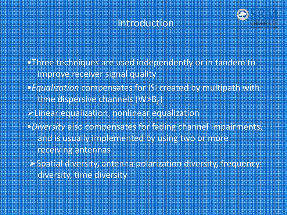
Introduction
•Three techniques are used independently or in tandem to improve receiver signal quality
•Equalization compensates for ISI created by multipath with time dispersive channels (W>BC)
Linear equalization, nonlinear equalization•Diversity also compensates for fading channel impairments,
and is usually implemented by using two or more receiving antennas
Spatial diversity, antenna polarization diversity, frequency diversity, time diversity

Diversity: It is the technique used to compensate for fading channel impairments. It is implemented by using two or more receiving antennas. While Equalization is used to counter the effects of ISI, Diversity is usually employed to reduce the depth and duration of the fades experienced by a receiver in a flat fading channel. These techniques can be employed at both base station and mobile receivers. Spatial Diversity is the most widely used diversity technique.
Diversity
Spatial Diversity Technique‐ A Brief Description
In this technique multiple antennas are strategically spaced and connected to common receiving system. While one antenna sees a signal null, one of the other antennas may see a signal peak, and the receiver is able to select the antenna with the best signal at any time. The CDMA systems use Rake receivers which provide improvement through time diversity.
• Unlike Equalization, Diversity requires no training overhead as a transmitter doesn’t require one.
• It provides significant link improvement with little added cost.
• It exploits random nature of wave propagation by finding independent ( uncorrelated) signal paths for communication.
Diversity Techniques‐ Highlights
ISI has been recognized as the major obstacle to high speed data transmission over mobile radio channels. Equalization is a technique used to combat inter symbol interference. As the mobile fading channels are random and time varying, equalizers must track the time varying characteristics of the mobile channel, and thus are called adaptive equalizers.
Fundamentals of Equalization

• It is a very simple concept where in one path undergoes a deep fade and another independent path may have a strong signal.
• As there is more than one path to select from, both the instantaneous and average SNRs at the receiver may be improved, often as much as 20‐30 dB
Diversity Techniques‐ Highlights
Channel coding: It is the technique which improves mobile communication link performance by adding redundant data bits in the transmitted message. In this technique, the base band portion of the transmitter, a channel coder maps a digital message sequence into another specific containing greater number of bits than originally contained in the message. The coded message is then modulated for transmission in the wireless channel.
Channel Coding
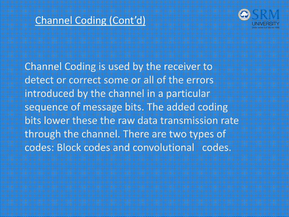
Channel Coding is used by the receiver to detect or correct some or all of the errors introduced by the channel in a particular sequence of message bits. The added coding bits lower these the raw data transmission rate through the channel. There are two types of codes: Block codes and convolutional codes.
Channel Coding (Cont’d)

Operating modes of adaptive equalizer
1) Training mode
2) Tracking Mode
DIVERSITY
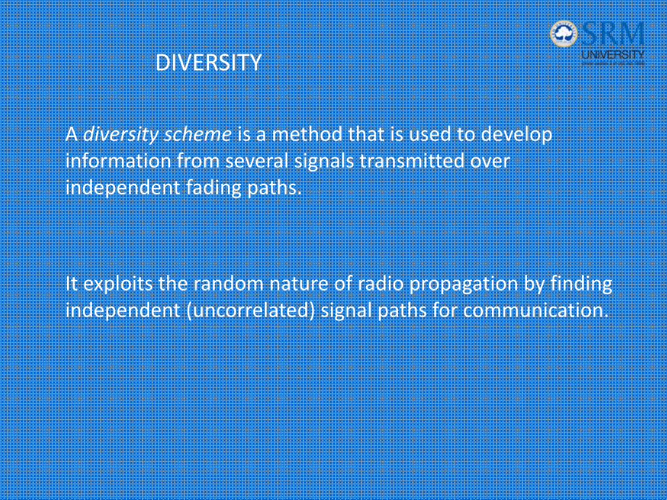
A diversity scheme is a method that is used to develop information from several signals transmitted over independent fading paths.
It exploits the random nature of radio propagation by finding independent (uncorrelated) signal paths for communication.
Diversity Technique
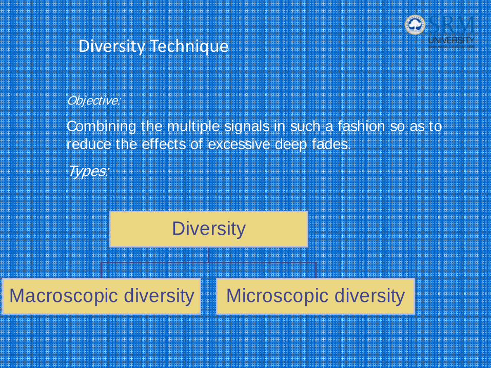
Macroscopic diversity Microscopic diversity
Diversity
Objective:
Combining the multiple signals in such a fashion so as to reduce the effects of excessive deep fades.
Types:
Types Of Diversity
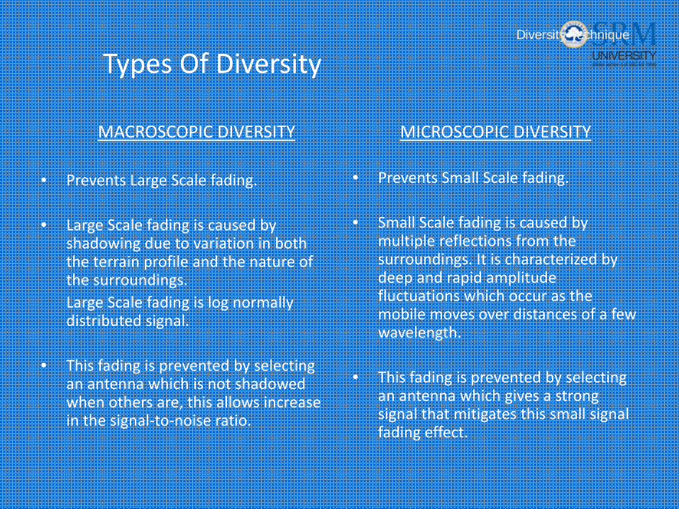
MACROSCOPIC DIVERSITY
• Prevents Large Scale fading.
• Large Scale fading is caused by shadowing due to variation in both the terrain profile and the nature of the surroundings.Large Scale fading is log normally distributed signal.
• This fading is prevented by selecting an antenna which is not shadowed when others are, this allows increase in the signal‐to‐noise ratio.
MICROSCOPIC DIVERSITY
• Prevents Small Scale fading.
• Small Scale fading is caused by multiple reflections from the surroundings. It is characterized by deep and rapid amplitude fluctuations which occur as the mobile moves over distances of a few wavelength.
• This fading is prevented by selecting an antenna which gives a strong signal that mitigates this small signal fading effect.
Diversity Technique
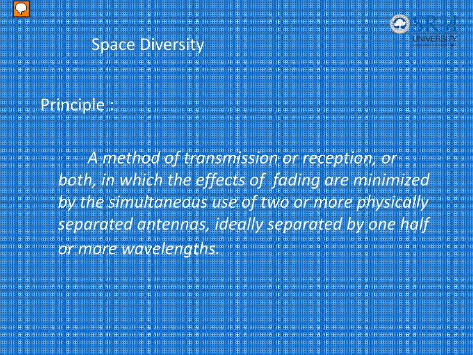
Space Diversity
Principle :
A method of transmission or reception, or both, in which the effects of fading are minimized by the simultaneous use of two or more physically separated antennas, ideally separated by one half or more wavelengths.
Presenter
Presentation Notes
Antenna diversity
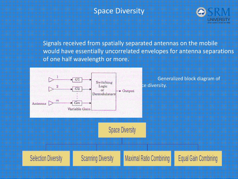
Space Diversity
Signals received from spatially separated antennas on the mobile would have essentially uncorrelated envelopes for antenna separations of one half wavelength or more.
Generalized block diagram of space diversity.
Selection Diversity Scanning Diversity Maximal Ratio Combining Equal Gain Combining
Space Diversity
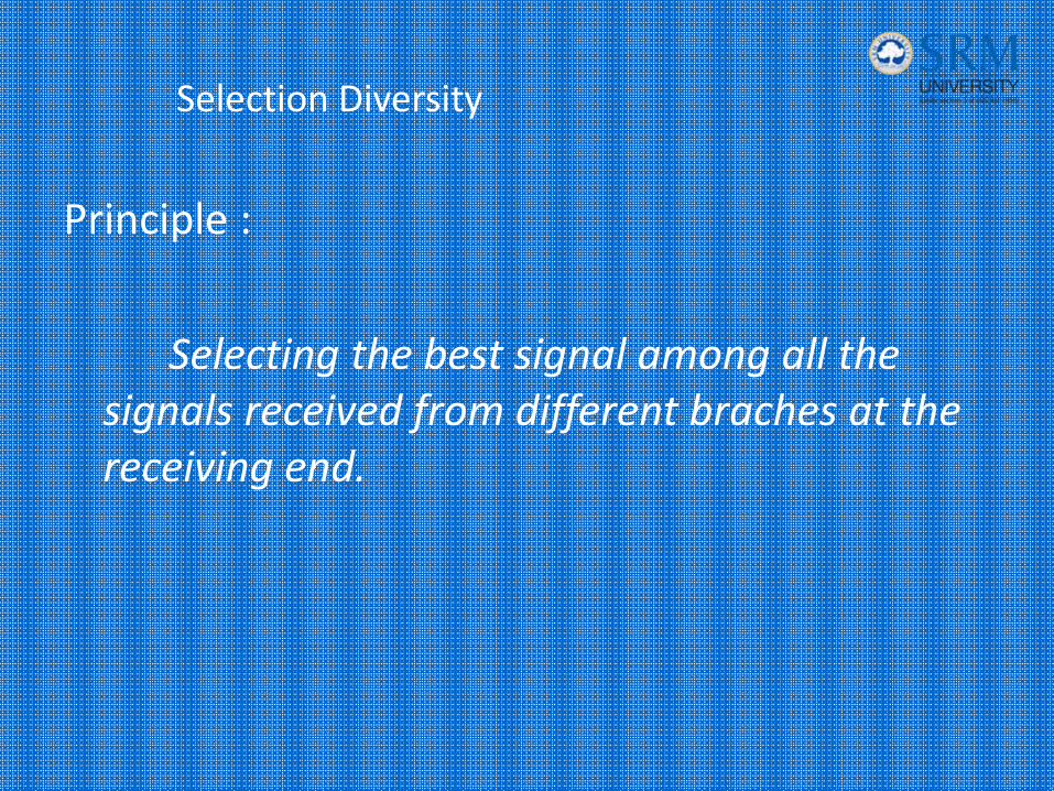
Selection Diversity
Principle :
Selecting the best signal among all the signals received from different braches at the receiving end.
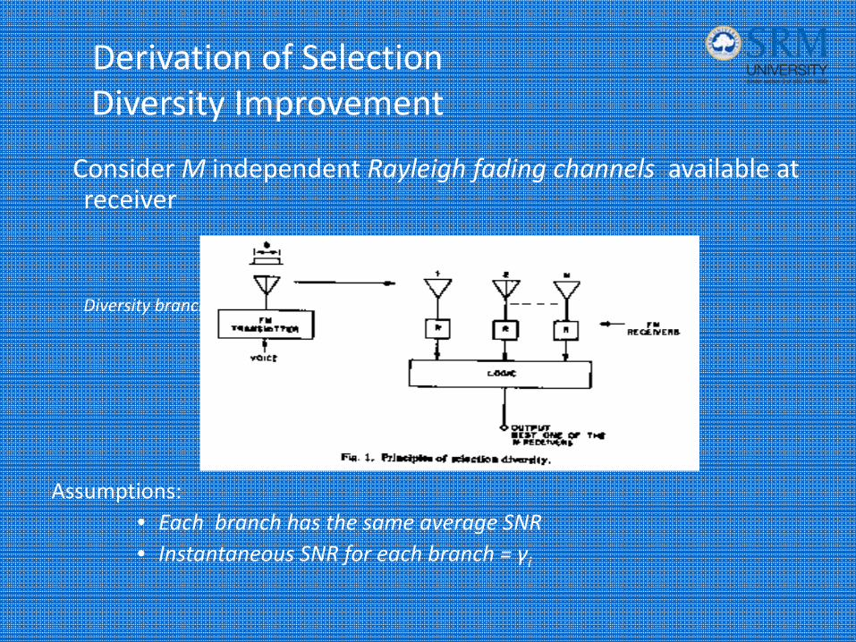
Derivation of Selection Diversity Improvement
Consider M independent Rayleigh fading channels available at receiver
Diversity branch
Assumptions:• Each branch has the same average SNR• Instantaneous SNR for each branch = γi
Selection Diversity
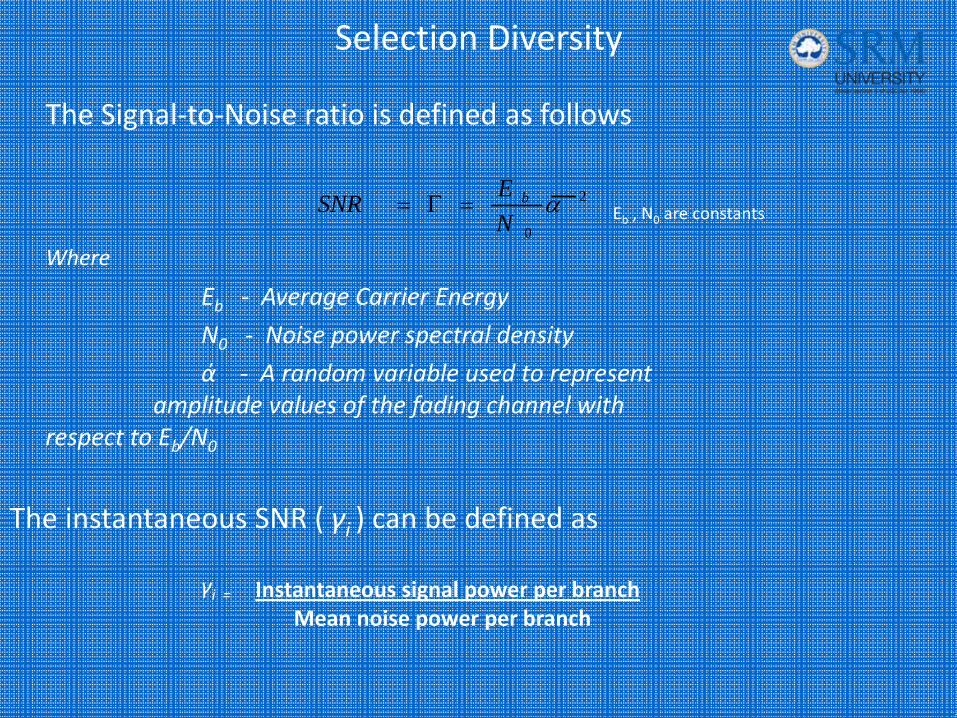
The Signal‐to‐Noise ratio is defined as follows
Eb , N0 are constants
Where
Eb ‐ Average Carrier Energy
N0 ‐ Noise power spectral density
ά ‐ A random variable used to represent amplitude values of the fading channel with
respect to Eb/N0
The instantaneous SNR ( γi ) can be defined as
2
0
αNESNR b=Γ=
Instantaneous signal power per branchMean noise power per branch
γi =

Selection Diversity (cont’d)
For Rayleigh fading channels, α has a Rayleigh
distribution and so α 2 and consequently γi have a
chi‐square distribution with two degrees of freedom.
The probability density function for such a channel is
The pdf for a single branch that has SNR less than some threshold γ is
0 exp1)( i ≥⎟⎠⎞
⎜⎝⎛
Γ−
Γ= γγγ i
ip
Γ−
−=Γ
−Γ
==≤ ∫∫γγγ
γγγγγγ eddpP ii
iiir 1)exp(1)()(00
Presenter
Presentation Notes
This is not a test, but a distribution. The Chi-square distribution, is derived from the Normal distribution. It is the distribution of a sum of squared Normal distributed variables. That is, if all Xi are independent and all have an identical, standard Normal distribution then X^2 = X1*X1 + X2*X2 + X3*X3 + ... + Xv*Xv is Chi-square distributed with v degrees of freedom with mean = v and variance = 2*v. �The importance of the Chi-square distribution stems from the fact that it describes the distribution of the Variance of a sample taken from a Normal distributed population.�Note that X^2 is a Sum of Squares and should be tested One-Sided only. The distribution of the underlying sample values X has mean = 0 and variance = 1, i.e., is Standard Normal. As a consequence, X^2 has mean equal to the Degrees of Freedom and a variance equal to 2 * Degrees of Freedom. Assumptions:�The values from which X^2 is calculated are themselves Normal distributed with unit variance.
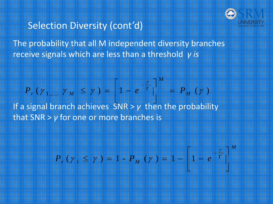
Selection Diversity (cont’d)
The probability that all M independent diversity branches receive signals which are less than a threshold γ is
If a signal branch achieves SNR > γ then the probability that SNR > γ for one or more branches is
)( 1)(M
,......1 γγγγγ
MMr PeP =⎥⎦
⎤⎢⎣
⎡−=≤ Γ
−
M
Mir ePP ⎥⎦
⎤⎢⎣
⎡−−==≤ Γ
−γ
γγγ 11 )(-1 )(
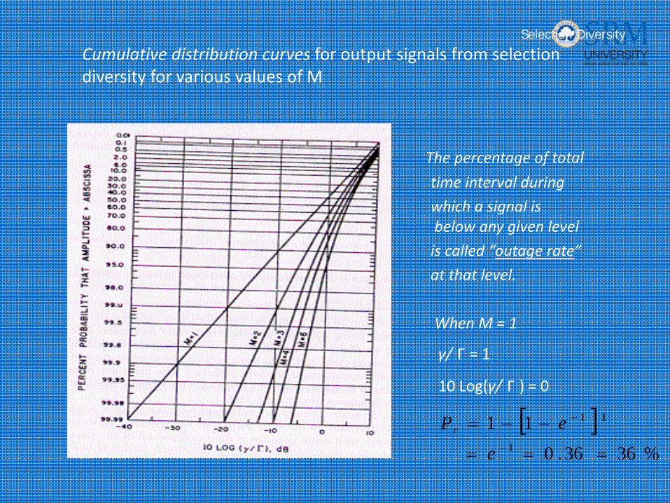
Cumulative distribution curves for output signals from selection diversity for various values of M
The percentage of total
time interval during
which a signal is below any given level
is called “outage rate”
at that level.
When M = 1
γ/ Г = 1
10 Log(γ/ Г ) = 0
Selection Diversity
[ ]%3636.0
11 1
11
===
−−=−
−
e
ePr
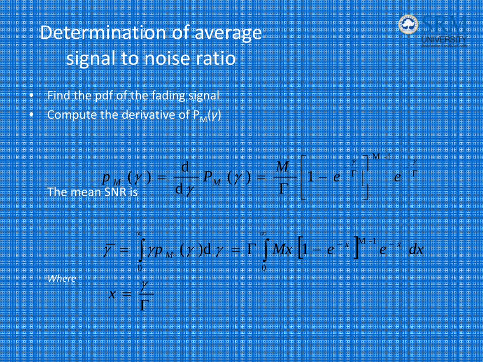
Determination of average signal to noise ratio
• Find the pdf of the fading signal
• Compute the derivative of PM(γ)
The mean SNR is
Where
1)(dd)(
1-M
Γ−
Γ−
⎥⎦
⎤⎢⎣
⎡−
Γ==
γγ
γγ
γ eeMPp MM
[ ] dxeeMxp xxM ∫∫
∞−−
∞
−Γ==0
1-M
0
1)d( γγγγ
Γ=γx
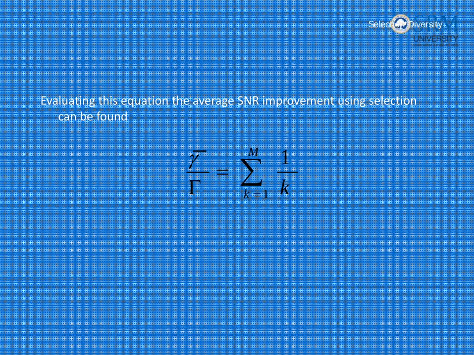
Evaluating this equation the average SNR improvement using selection can be found
∑=
=Γ
M
k k1
1γ
Selection Diversity
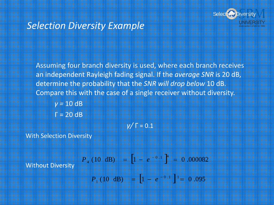
Selection Diversity Example
Assuming four branch diversity is used, where each branch receives an independent Rayleigh fading signal. If the average SNR is 20 dB, determine the probability that the SNR will drop below 10 dB. Compare this with the case of a single receiver without diversity.
γ = 10 dB
Г = 20 dB
γ/ Г = 0.1With Selection Diversity
Without Diversity[ ] .0000820 1dB)10( 41.0
4 =−= −eP
[ ] .0950 1dB)10( 11.01 =−= −eP
Selection Diversity
Conclusion
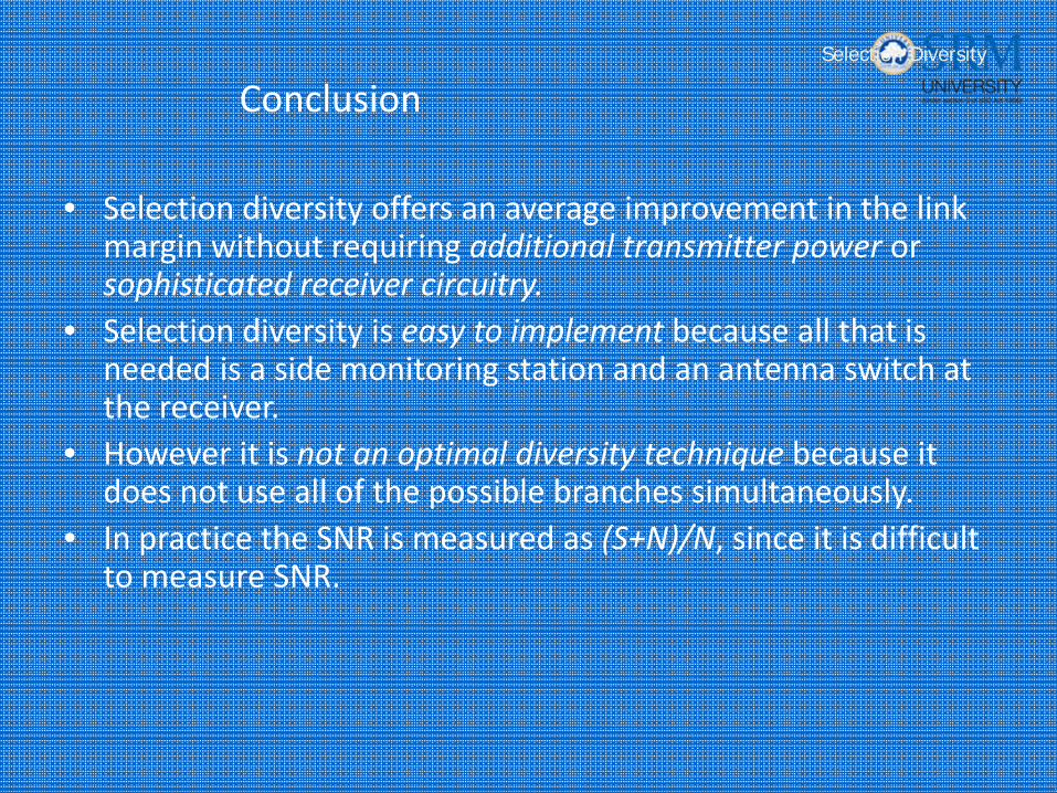
• Selection diversity offers an average improvement in the link margin without requiring additional transmitter power or sophisticated receiver circuitry.
• Selection diversity is easy to implement because all that is needed is a side monitoring station and an antenna switch at the receiver.
• However it is not an optimal diversity technique because it does not use all of the possible branches simultaneously.
• In practice the SNR is measured as (S+N)/N, since it is difficult to measure SNR.
Selection Diversity
Conclusion
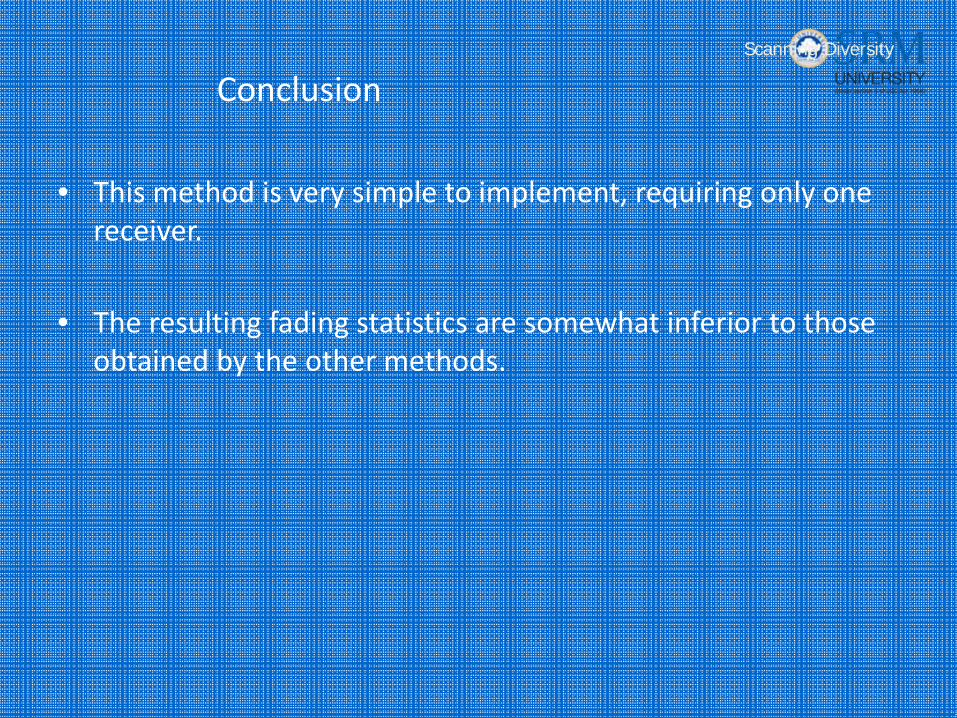
• This method is very simple to implement, requiring only one receiver.
• The resulting fading statistics are somewhat inferior to those obtained by the other methods.
Scanning Diversity
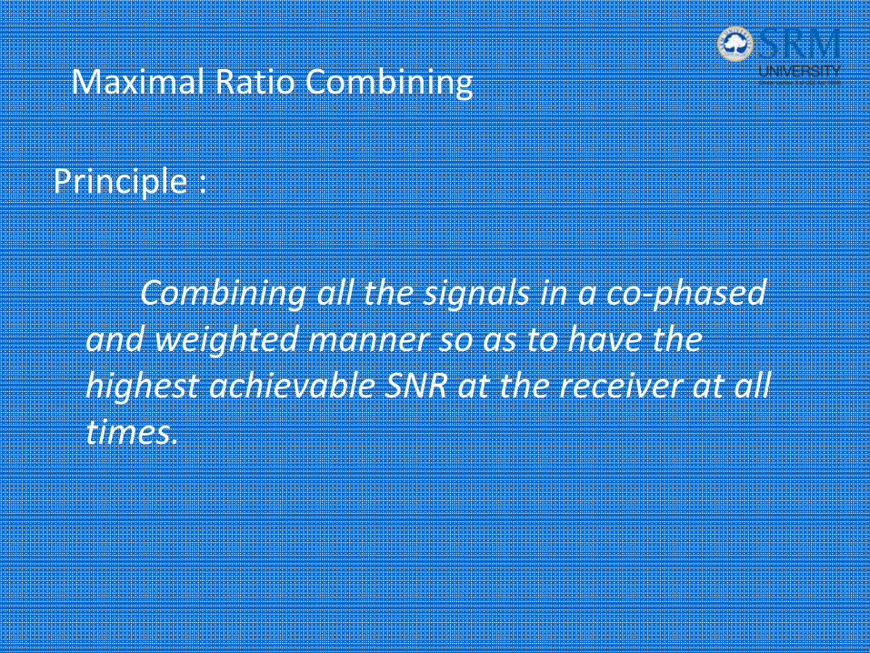
Maximal Ratio Combining
Principle :
Combining all the signals in a co‐phased and weighted manner so as to have the highest achievable SNR at the receiver at all times.
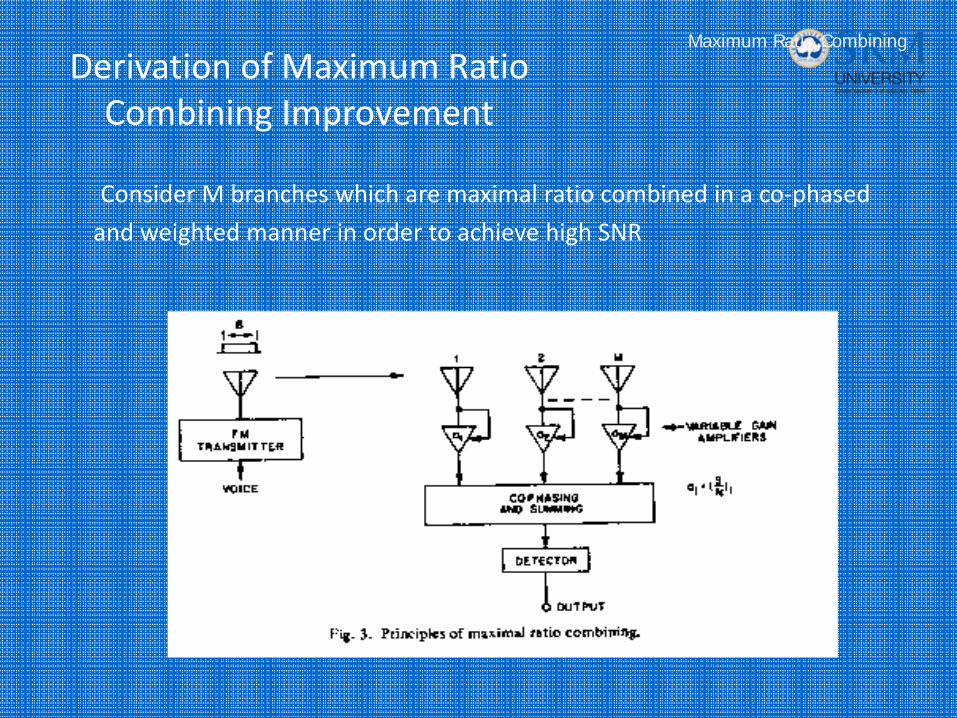
Derivation of Maximum Ratio Combining Improvement
Consider M branches which are maximal ratio combined in a co‐phased
and weighted manner in order to achieve high SNR
Maximum Ratio Combining
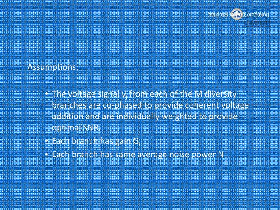
Assumptions:
• The voltage signal γi from each of the M diversity branches are co‐phased to provide coherent voltage addition and are individually weighted to provide optimal SNR.
• Each branch has gain Gi
• Each branch has same average noise power N
Maximal Ratio Combining
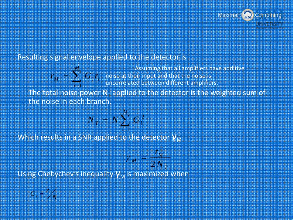
Resulting signal envelope applied to the detector isAssuming that all amplifiers have additive
noise at their input and that the noise is uncorrelated between different amplifiers.
The total noise power NT applied to the detector is the weighted sum of the noise in each branch.
Which results in a SNR applied to the detector γM
Using Chebychev’s inequality γM is maximized when
Maximal Ratio Combining
∑=
=M
iiiM rGr
1
∑=
=M
iiT GNN
1
2
T
MM N
r2
2
=γ
NrG i
i =
Maximal Ratio Combining
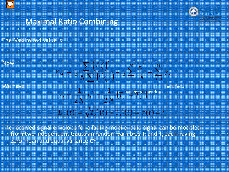
The Maximized value is
Now
We have The E field received envelop
The received signal envelope for a fading mobile radio signal can be modeled from two independent Gaussian random variables Tc and Ts each having zero mean and equal variance σ2 .
( )( ) ∑∑∑
∑==
===M
ii
M
i
i
Nr
Nr
M Nr
N i
i
11
2
21
2
21
2
2
2
γγ
( )222
21
21
scii TTN
rN
+==γ
iscz rtrtTtTtE ==+= )()()()( 22
Presenter
Presentation Notes
Thus the snr out of the
Maximal Ratio Combining
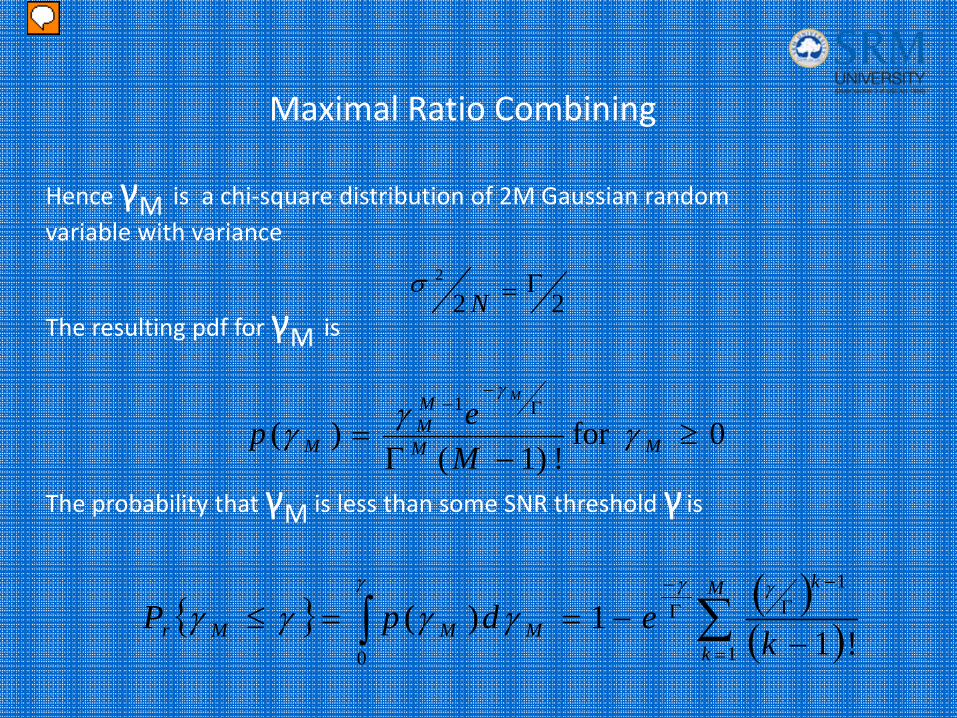
Hence γM is a chi‐square distribution of 2M Gaussian random variable with variance
The resulting pdf for γM is
The probability that γM is less than some SNR threshold γ is
222 Γ=N
σ
0for ! )1(
)(1
≥−Γ
=Γ
−−
MM
MM
M Mep
M
γγγγ
{ } ( )( )∑∫
=
−ΓΓ
−
−−==≤
M
k
k
MMMr kedpP
1
1
0 ! 11)(
γγ γ
γγγγ
Presenter
Presentation Notes
Thus the snr out of the
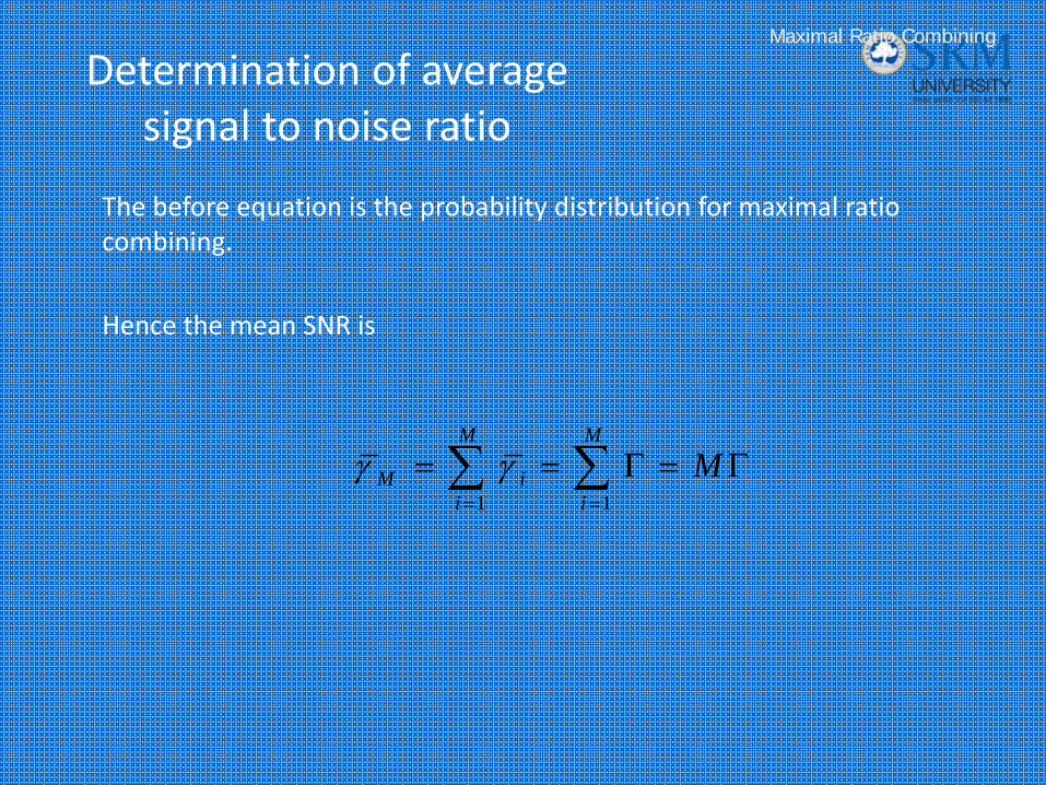
Determination of average signal to noise ratio
The before equation is the probability distribution for maximal ratio combining.
Hence the mean SNR is
Maximal Ratio Combining
Γ=Γ== ∑∑==
MM
i
M
iiM
11γγ
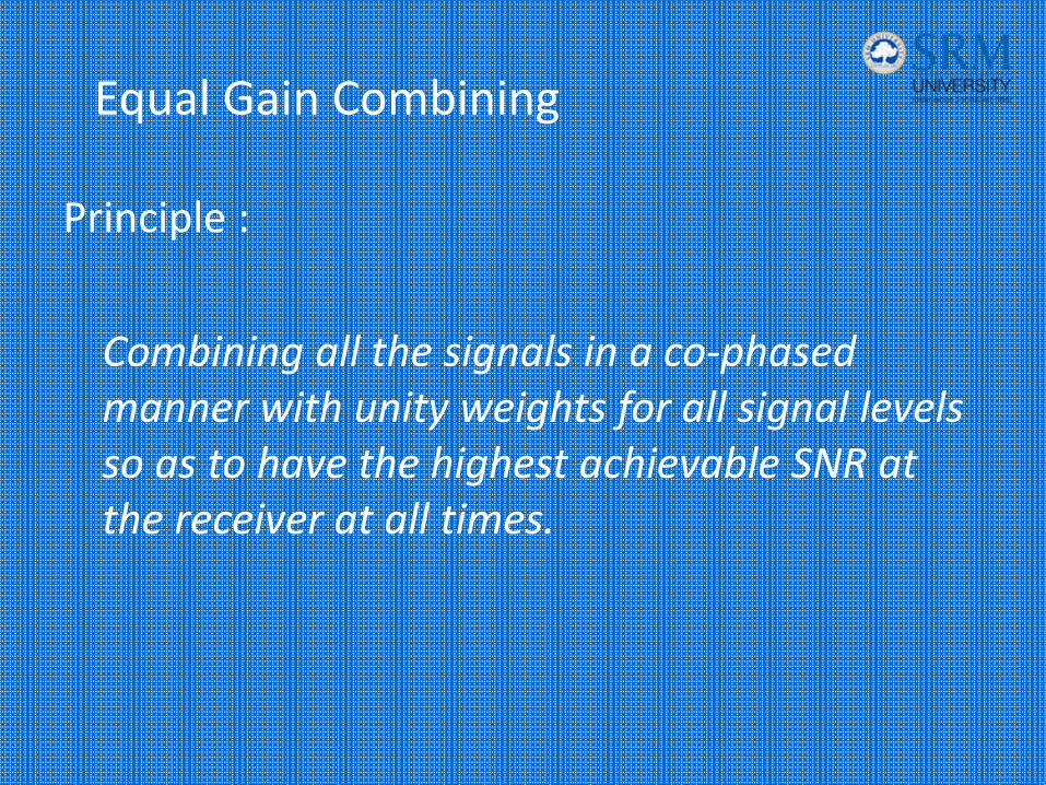
Equal Gain Combining
Principle :
Combining all the signals in a co‐phased manner with unity weights for all signal levels so as to have the highest achievable SNR at the receiver at all times.
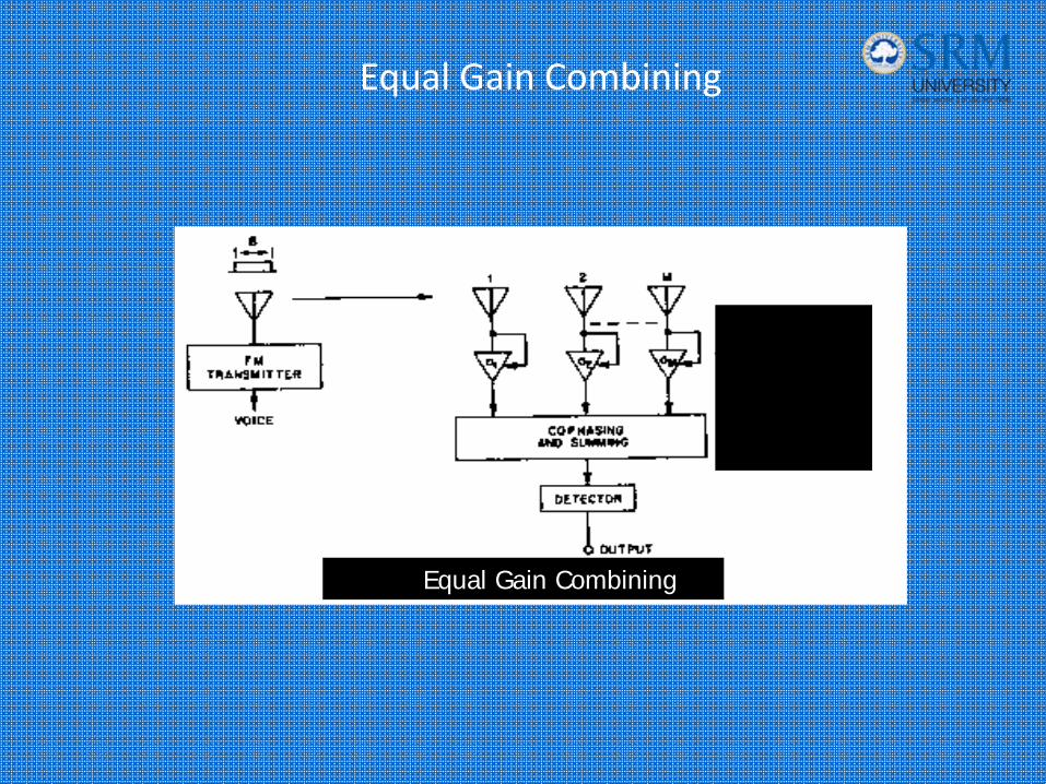
Equal Gain Combining
Equal Gain Combining
Equal Gain Combining
• In certain cases it is not convenient to provide for the variable weighting capability.
• This allows the receiver to exploit signals that are simultaneously received on each branch.
• The probability of producing an acceptable signal from a number of unacceptable inputs is still retained.
• The performance is marginally inferior to maximal ratio combining and superior to selection Diversity.
Polarization Diversity
Principle :
Polarization diversity relies on the decorrelation of the two receive ports to achieve diversity gain. The two receiver ports must remain cross-polarized.
Presenter
Presentation Notes
Many wireless service providers have discussed the adoption of a polarization diversity scheme in place of a space diversity approach. Like space diversity, polarization diversity relies on the decorrelation of the two receive ports to achieve diversity gain. The diversity gain from polarization diversity is maximized if the dual-polarized antenna has receive and receive diversity ports that receive radiation in a cross-polarized fashion over the desired coverage area with equal field strengths. Stated in another way, in a typical sectorized system, the two receive ports must remain cross-polarized (i.e., orthogonal) and capable of tracking one another over the forward 120-degree sector and into the hand-over area. The orthogonality, combined with tracking ability, is necessary if systems using dual-polarized antennas in a polarization diversity scheme with an advanced combining technique are to perform as well as systems employing vertically polarized antennas in a horizontal space diversity format.

Polarization Diversity
Effective Diversity is obtained with a Correlation Coefficient below 0.7
In order to keep the correlation at this level
• space diversity at a base station requires antenna spacing of up to 20 wavelengths for the broadside case, and even more for the inline case.
• Polarization diversity at a base station does not require antenna spacing.
Polarization Diversity(cont’d)
– At the base station, space diversity is considerably less practical than at the mobile because the narrow angle of incident fields requires large antenna spacing.
– The comparatively high cost of using space diversity at the base station prompts the consideration of using orthogonal polarization.
– Polarization diversity provides two diversity branches and allows the antenna elements to be considered.
Polarization Diversity
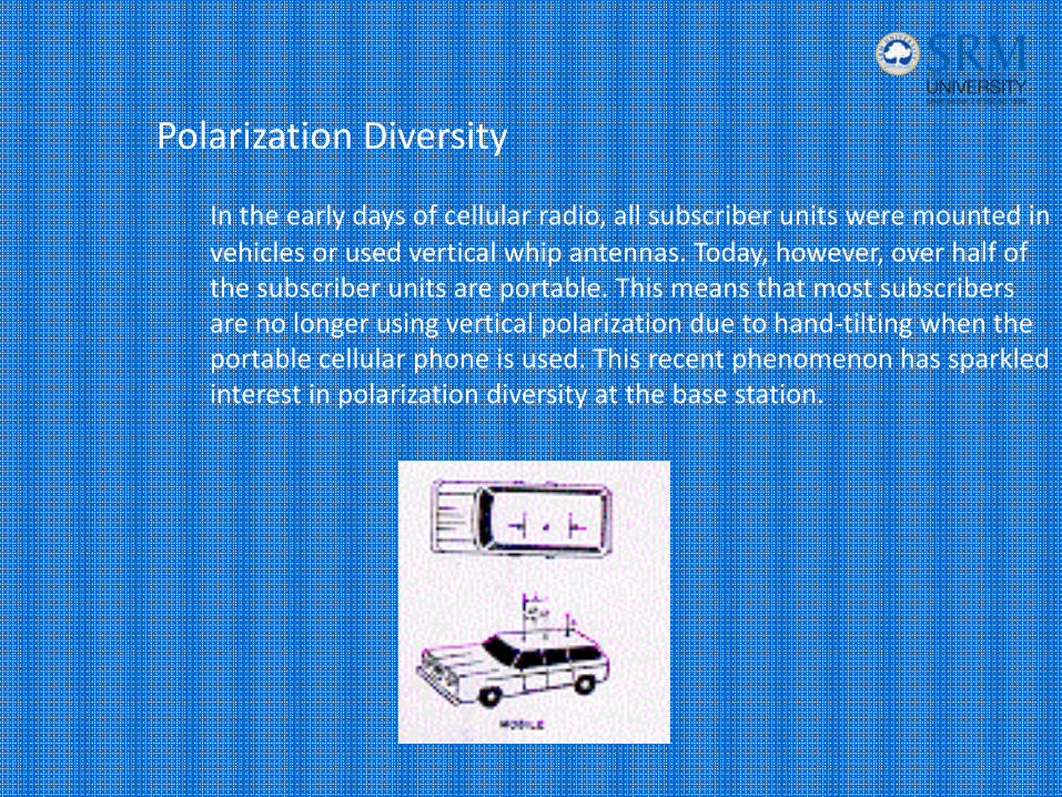
In the early days of cellular radio, all subscriber units were mounted in vehicles or used vertical whip antennas. Today, however, over half of the subscriber units are portable. This means that most subscribers are no longer using vertical polarization due to hand‐tilting when the portable cellular phone is used. This recent phenomenon has sparkled interest in polarization diversity at the base station.
Frequency Diversity
Principle :
The same information signal is transmitted and received simultaneously on two or more independent fading carrier frequencies.
Frequency Diversity
– The rational behind this technique is that frequencies separated by more than the coherence bandwidth of the channel will not experience the same fade.
– The probability of simultaneous fade will be the product of the individual fading probabilities.
– This is often employed in microwave LOS links which carry several channels in a frequency division multiplex mode(FDM).
Frequency Diversity
– This technique not only requires spare bandwidth, but also requires that there be as many receivers as there are channels used for the frequency diversity.
However, for critical traffic, the expense may be justified.
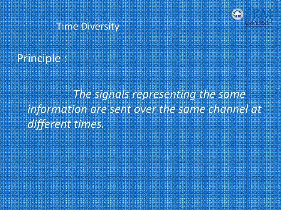
Time Diversity
Principle :
The signals representing the same information are sent over the same channel at different times.
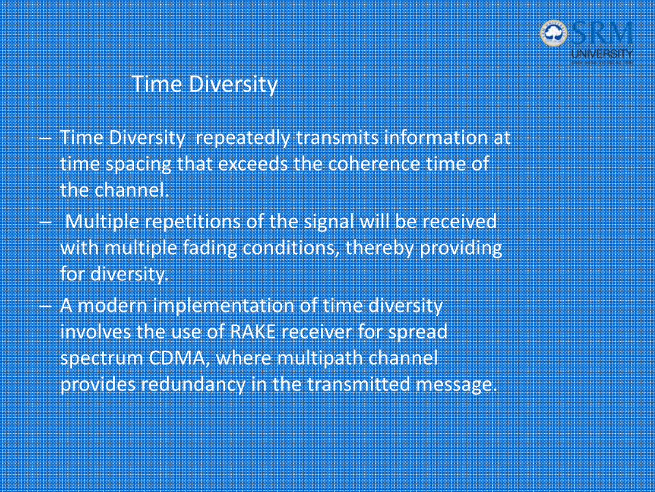
Time Diversity
– Time Diversity repeatedly transmits information at time spacing that exceeds the coherence time of the channel.
– Multiple repetitions of the signal will be received with multiple fading conditions, thereby providing for diversity.
– A modern implementation of time diversity involves the use of RAKE receiver for spread spectrum CDMA, where multipath channel provides redundancy in the transmitted message.
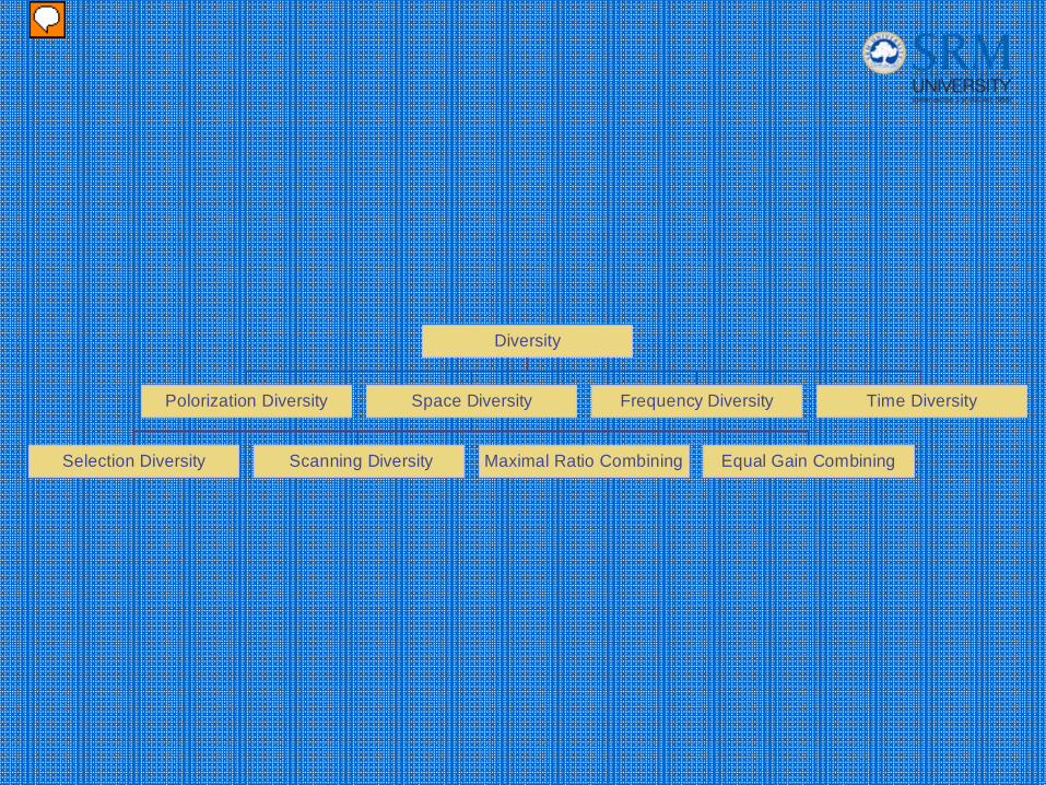
Polorization Diversity
Selection Diversity Scanning Diversity Maximal Ratio Combining Equal Gain Combining
Space Diversity Frequency Diversity Time Diversity
Diversity
Presenter
Presentation Notes
summary
References
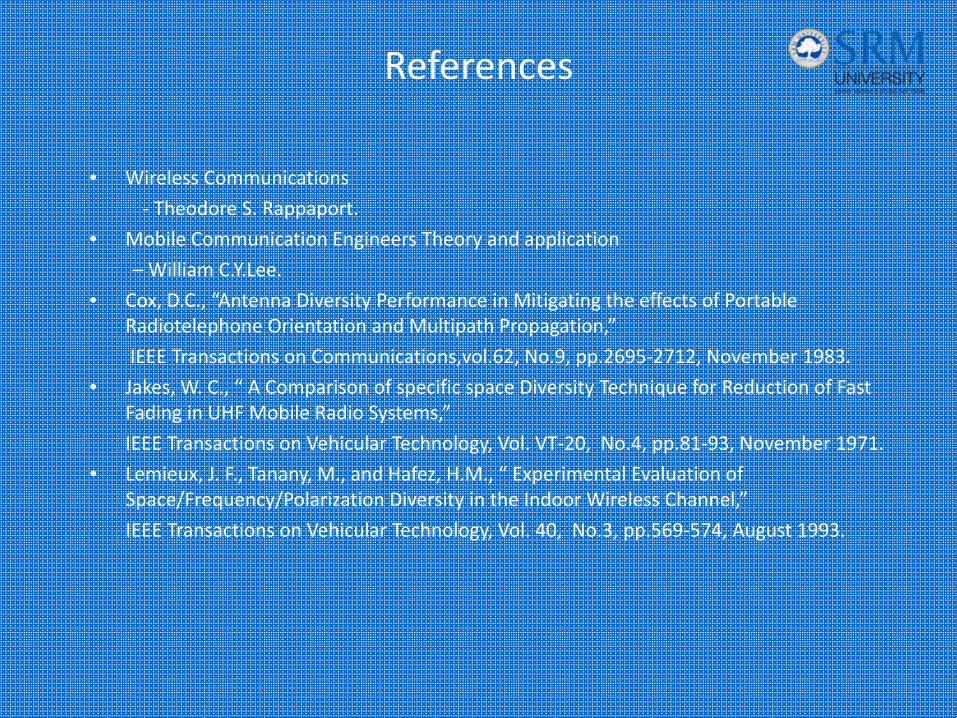
• Wireless Communications
‐ Theodore S. Rappaport.
• Mobile Communication Engineers Theory and application
– William C.Y.Lee.
• Cox, D.C., “Antenna Diversity Performance in Mitigating the effects of Portable Radiotelephone Orientation and Multipath Propagation,”
IEEE Transactions on Communications,vol.62, No.9, pp.2695‐2712, November 1983.
• Jakes, W. C., “ A Comparison of specific space Diversity Technique for Reduction of Fast Fading in UHF Mobile Radio Systems,”
IEEE Transactions on Vehicular Technology, Vol. VT‐20, No.4, pp.81‐93, November 1971.
• Lemieux, J. F., Tanany, M., and Hafez, H.M., “ Experimental Evaluation of Space/Frequency/Polarization Diversity in the Indoor Wireless Channel,”
IEEE Transactions on Vehicular Technology, Vol. 40, No.3, pp.569‐574, August 1993.
References
• Rappaport, T.S., and Hawbaker, D.A, “Wide band Microwave Propagation Parameters Using Circular Frequency Reuse Efficiency for the Reverse Channel ,”IEEE Transactions on Vehicular Technology, Vol. 40, No.2, pp.231‐242, February 1992.
• Vaughan , R., “ Polarization Diversity in Mobile Communications,”IEEE Transactions on Vehicular Technology, Vol. 39, No.3, pp.177‐186, August 1990.
• Kozono , S., “ Base Station Polarization Diversity Reception for Mobile Radio,”IEEE Transactions on Vehicular Technology, Vol. VT‐33, No.4, pp.301‐306, November 1985.
• Lee, W.C.Y, “ Polarization Diversity System for Mobile Radio,”IEEE Transactions on Communications, Vol. 20, pp.912‐922, October 1972.
References
[10] G. D. Forney, “The Viterbi algorithm, ” Proceedings of the IEEE, vol.61, no.3, pp. 268‐‐278, March 1978.
[11] B. Widrow, and S.D. Stearns, Adaptive Signal Processing, Prentice Hall, 1985.
[12] S. Haykin, Adaptive Filter Theory, Prentice Hall, Englewood Cliffs, NJ, 1986.
[13] T. Eng, N. Kong, and L. B. Milstein, “Comparison of Diversity Combining Techniques for Rayleigh‐Fading Channels,” IEEE Trans. Commun., vol. 44, pp. 1117‐1129, Sep. 1996.
[14] W. C. Jakes, “A Comparision of Space Diversity Techniques for Reduction of Fast Fading in UHF Mobile Radio Systems,” IEEE Trans. Veh. Technol., vol. VT‐20, No. 4, pp. 81‐93,
Nov. 1971.
[15] L. Kahn, “Radio Square,” Proceedings of IRE, vol. 42, pp. 1074, Nov. 1954.
[16] S. Kozono, et al, “Base Station Polarization Diversity Reception for Mobile Radio,” IEEE Trans. Veh. Technol., vol VT‐33, No. 4, pp. 301‐306, Nov. 1985.
[17] R. Price, P. E. Green, “A Communication Technique for Multipath Channel,” Proceeding of the IRE, pp. 555‐570, March 1958