JOURNAL OF TECHNIQUES
13
Journal of Techniques, ISSN: 2708-8383, Vol. 3, No. 3, September 30, 2021, Pages 31-43 31 RESEARCH ARTICLE - ENGINEERING Design and Implementation of Multifunction Relay Based on Microcontroller Ali Abdulsattar Hameed 1,3 , Ahmed Jasim Sultan 1 , Mehdi F. Booneya 2 1 Electrical Power Engineering Techniques Dept., Electrical Engineering Technical College, Middle Technical University, Baghdad, Iraq. 2 Kut Technical Institute, Middle Technical University, Baghdad, Iraq. 3 Industrial Development & Research, Ministry of Science & Technology, Iraq. * Corresponding author E-mail: [email protected] Article Info. Abstract Article history: Received 26 June 2021 Accepted 13 August 2021 Publishing 30 September 2021 The power systems are exposed to many abnormal conditions, so an advanced protection system must be provided to stand up to these challenges. Protection devices evolved continuously with the development of power systems. The accuracy, high response, reliability, and speed of fault detection are required in the operating mode of multi-function protective relays. A Multifunction Relay has been designed and implemented, which consists of three types of relays: over current relay OCR, over/under voltage relay OVR/UVR, and differential relay DFR. The relays OCR, OVR/UVR, and DFR are designed according to the standards IEC 60255, IEEE 1159, and IEEE C37.91, respectively, based on Arduino MEGA. The multi-function relay was implemented to work on a single phase. The setting of the multi-function relay configuration done using a new design based on the MATLAB GUI environment. Furthermore, the results obtained after each test appear on it and LCD screen. The multi-function relay which is designed can work as (OCR, OVR/UVR, DFR) in the case of a single-phase source. The experiential results show that the proposed multi-function relay is accurate, fast response, reliable, selective, good performance, low cost, and sensitivity when used to protect the power system equipment under different operating conditions. 2019 Middle Technical University. All rights reserved Keywords: Multifunction Relay; Overcurrent Relay; Arduino MEGA; PZEM004-T Sensor; Extremely Inverse; Temporary 1. Introduction The rapid development in the production of electric power and the accompanying development in equipment, transmission lines, transmission, and distribution stations contributed to the development of the protection systems. Protection devices are an essential part of the electric power system and an important part of modern advanced protection systems [1]. A strong protection system is necessary to stand firmly in front of these challenges. There are several protection methods in the power system to prevent any change in electrical values that occurs suddenly [2]. Protection relays are developed to match the growth and development of the complex power system. The biggest revolution in protection systems was the invention of a microprocessor in 1971 when a microprocessor-based relay was developed after a short period of this invention [2]. The modern protection relay depending on the microprocessor. The microprocessor relay is one of the software devices that is based on numerical measurement [3]. There are several types of protection relay classified according to the nature of the need and the work. The first type of protection relay is overcurrent. The overcurrent Relay (OCR) is widely used in transmission and distribution systems to protect the ring and radial system [4]. The overcurrent relay is mainly used in power systems as backup protection in power systems [2]. The directional overcurrent (DOR) differs from the Overcurrent (OCR) by one point is the DOR measure the value of the current in addition to the angle, while the OCR measures the current value only [5]. JOURNAL OF TECHNIQUES Journal homepage: http://journal.mtu.edu.iq
-
Upload
khangminh22 -
Category
Documents
-
view
0 -
download
0
Transcript of JOURNAL OF TECHNIQUES
Journal of Techniques, ISSN: 2708-8383, Vol. 3, No. 3, September 30, 2021, Pages 31-43
31
RESEARCH ARTICLE - ENGINEERING
Design and Implementation of Multifunction Relay Based on
Microcontroller
Ali Abdulsattar Hameed1,3, Ahmed Jasim Sultan1, Mehdi F. Booneya2
1 Electrical Power Engineering Techniques Dept., Electrical Engineering Technical College, Middle Technical University, Baghdad, Iraq.
2 Kut Technical Institute, Middle Technical University, Baghdad, Iraq.
3 Industrial Development & Research, Ministry of Science & Technology, Iraq.
* Corresponding author E-mail: [email protected]
Article Info. Abstract
Article history:
Received
26 June 2021
Accepted
13 August 2021
Publishing
30 September 2021
The power systems are exposed to many abnormal conditions, so an advanced protection system must be provided to stand up to these challenges. Protection devices evolved continuously with the development of power systems. The accuracy,
high response, reliability, and speed of fault detection are required in the operating mode of multi-function protective
relays. A Multifunction Relay has been designed and implemented, which consists of three types of relays: over current relay OCR, over/under voltage relay OVR/UVR, and differential relay DFR. The relays OCR, OVR/UVR, and DFR are
designed according to the standards IEC 60255, IEEE 1159, and IEEE C37.91, respectively, based on Arduino MEGA.
The multi-function relay was implemented to work on a single phase. The setting of the multi-function relay configuration done using a new design based on the MATLAB GUI environment.
Furthermore, the results obtained after each test appear on it and LCD screen. The multi-function relay which is designed
can work as (OCR, OVR/UVR, DFR) in the case of a single-phase source. The experiential results show that the proposed multi-function relay is accurate, fast response, reliable, selective, good
performance, low cost, and sensitivity when used to protect the power system equipment under different operating
conditions.
2019 Middle Technical University. All rights reserved
Keywords: Multifunction Relay; Overcurrent Relay; Arduino MEGA; PZEM004-T Sensor; Extremely Inverse; Temporary
1. Introduction
The rapid development in the production of electric power and the accompanying development in equipment, transmission lines, transmission,
and distribution stations contributed to the development of the protection systems. Protection devices are an essential part of the electric power
system and an important part of modern advanced protection systems [1]. A strong protection system is necessary to stand firmly in front of
these challenges. There are several protection methods in the power system to prevent any change in electrical values that occurs suddenly [2].
Protection relays are developed to match the growth and development of the complex power system. The biggest revolution in protection
systems was the invention of a microprocessor in 1971 when a microprocessor-based relay was developed after a short period of this invention
[2]. The modern protection relay depending on the microprocessor. The microprocessor relay is one of the software devices that is based on
numerical measurement [3].
There are several types of protection relay classified according to the nature of the need and the work. The first type of protection relay is
overcurrent. The overcurrent Relay (OCR) is widely used in transmission and distribution systems to protect the ring and radial system [4]. The
overcurrent relay is mainly used in power systems as backup protection in power systems [2]. The directional overcurrent (DOR) differs from
the Overcurrent (OCR) by one point is the DOR measure the value of the current in addition to the angle, while the OCR measures the current
value only [5].
JOURNAL OF TECHNIQUES
Journal homepage: http://journal.mtu.edu.iq

Ali A. H. et.al, Journal of Techniques, Vol. 3, No. 3, September 30, 2021, Pages 31-43
32
Nomenclature
MFR Multifunction Relay CT Current Transformer
OCR Overcurrent Relya PT Potential Transformer OVR Overvoltage Relay TFT Thin-Film-Transistor
DFR Differential Relay TFT Thin-Film-Transistor
The principle work of OCR is if the flowing current through the system exceeds the set value in a relay, the relay directly disconnects the current
to provide the required protection.
There are some types of Overcurrent relay [1-2]:
1- Instantaneous Overcurrent Relay.
2- Definite Time Overcurrent Relay.
3- Inverse Time Overcurrent Relay.
4- Vary Inverse Overcurrent Relay.
5- Extremely Inverse Overcurrent Relay.
The second type is the overvoltage relay. The over/under voltage is an abnormal voltage that occurs as a result of special, unusual conditions
in the power system. This voltage formed as a result of excessive voltage in the transformer, generator which leads to a failure in the equipment
that must be protected [6]. Most electrical equipment, such as transformers or generators, is designed on voltages that can withstand up and
down in voltage. In the event of overvoltage, devices are designed to work on a voltage between (105-110%) of the normal voltage, Whereas,
in the case of the voltage drop, the devices are designed to work on voltages in the range) 90% (of the normal voltage. For these reasons, devices
that sense the rise and fall of voltage are designed to send a signal to the circuit breaker when such situations occur, called over / under voltage
Relay. The third type of protection relay is the Differential relay. Differential protection is a unit that provides instantaneous protection used
to protect specific equipment such as the generator, transformer, motor, etc., but is more used in transformers [7]. The function of the differential
protection Relay is comparing the incoming and outgoing currents of the element to be protected; if the difference between two values exceeds
a certain value, this means that a fault occurs inside the transformer. As a result, a signal is sent from DFR to the circuit breaker to disconnect
the current from the element to protect it from breakdown [5-7]. In any electrical power system, an inrush current (magnetizing current) is
generated from an energized transformer [8]. The value of the Inrush current is between 1-2% of the rated current value when the transformer
in the steady state, while the Inrush current value is more than 8-30 times the rated current when the transformer is energized [2]. The design
of the protection digital relay consists of some inputs such as voltage, current, etc. The Current is measured by the current transformer while
voltage is measured by the potential transformer [9]. Any electrical power system must contain a set of protection systems such as Over-current,
Over and under voltage, differential protection, etc. [1-5]. The MFR contains several self-operating relays when exceeding the values passing
through the power system, the values stored inside the relay, the relay sends a signal at high response speed to the circuit breaker to perform
the protection function assigned to it. The fault in the power system usually occurs but not continuously. One of the basics of the multi-function
relay is to distinguish faults between acceptable conditions and unacceptable conditions, and these conditions include increased current, high
and low voltage, change impedance, frequency, etc. [10] .
This work aims to design a multi-functional relay that contains the main requirements for the electrical network. The MFR includes several
protection devices such as (overcurrent relay, over/under voltage relay m differential relay, etc.).
1.1. Literature Review
In 2017, Deshmukh et al. [11] implemented a differential relay to protect the transformer using fuzzy logic to distinguish between fault state
and normal states using MATLAB software by selecting an appropriate slope for the differential protection of 25% .The practical part was
implemented using two current transducers and a microcontroller from type dsPIC33E, operating as a part of the fuzzy logic controller. The
result did not base on IEEE standardized; also, the researcher did not perform all the tests on the transformer.
In 2018, Majumder et al. [12] implemented an overcurrent relay from type inverse definite minimum time (IDMT). The protection system was
tested on three-phase transmission lines, depending on the signal conversion method from analog to digital. The current value is sensed using
a hall effect sensor (ACS712). The researchers did not implement all overcurrent relay types such as (vary inverse, extremely inverse). Also,
the hall effect sensor was used inaccurately to measure currents .
In 2018, Kotb et al. [13] designed and implemented of over / under voltage relay for the protection of the solid-state transformer using the
microcontroller Arduino from type UNO. The system is built using the proteus program. The transformer chosen consider a branch of future
renewable electric energy delivery and management. The results showed inaccurate sensors to measure voltage compare to the modern sensors.
Also, the researchers did not implement all overvoltage relay types according to IEEE standards.
In 2019, Kotb et al. [14] designed and implemented an overcurrent relay using Arduino from UNO type as a microcontroller. The author used
the proteus program to build the schemes. The relay is used to protect the Future Renewable Electric Energy Delivery and Management from
any increase in current value as backup protection. The design is depending on standardized IEC 60255-151 to implement three types of OCR
which are (normally inverse, very inverse, and Extremely inverse) for different TDS values. The researchers did not implement all overcurrent
relay types according to IEEE standards such as (vary inverse, extremely inverse) in real-time.
In 2020, Rahebi et al. [15] designed and implemented a model for a multi-function relay using a three-phase transmission line system. Different
type of multi-function relay was implemented such as (over/under voltage, over current, and over/ under frequency). The MFR design is built
using MATLAB SIMULINK. The prototype used different tests such as (overload, change the voltage value, and change the frequency) to
Ali A. H. et.al, Journal of Techniques, Vol. 3, No. 3, September 30, 2021, Pages 31-43
33
make fault in the system. The researchers did not design the proposed model in real-time. Also, the researchers did not implement all protection
relay types according to IEEE standards.
This work aims to design a multi-functional relay to implement the protection requirements of the electrical power system. The MFR contains
more than one relay. Each relay works according to characteristics. The MFR consists of three types of the relay (overcurrent relay, over/under
voltage relay, differential relay).
This paper consists of (MFR problem, Overcurrent relay, Inverse definite minimum time, extremely inverse, Very inverse, Over/under voltage
relay, differential relay, the proposed MFR, the experiential results and conclusion).
2. MFR Problem
Protection relay devices in power systems monitor the flow of power continuously to ensure the continuity of electricity and ensuring the least
damage to electrical equipment [16]. The proposed MFR is one of the essential parts of a modern power system. The MFR interface is designed
by using MATLAB GUI software. The MFR consists of several protection relays that are used according to protection degree, such as (OCR,
OVR, UVR, and DFR).
2.1. Overcurrent relay
The development of power systems is important to provide electric energy with high quality to consumers and to keep up with demand
increasing. Over-current protection was evolved many years ago [3]. It is one of the simplest, cheapest, and most popular protection systems in
the world. The working principle of Overcurrent Relay is when a fault occurs in the power system, the value of the current measured by the
OCR increases, the relay compares the measured value with the setting value if the measured value is greater than the setting value and continues
for a period of time, the relay directly sends a trip signal to separate the current from the part to be protected, three types of overcurrent can be
classified according to delay time [12]:
1- Inverse definite minimum time
2- Vary Inverse Overcurrent Relay
3- Extremely Inverse Overcurrent Relay.
2.1.1. Inverse definite minimum time
The disadvantage of inverse time-current is the operating time is not specified for the higher fault current; hence it is difficult to obtain good
coordination between relays. To avoid this problem, we can adjust the relay to get an operation time at a definite minimum have a PSM (Plug
setting multiplier) value. Therefore, the relay characteristic becomes an inverse relationship between the time and the current values that are
less than PSM, and a straight line with values above PSM. In this type of relay, the operating time of the relays connected to different zones of
the feeders is set even at the minimum operating time of the relays to make true separation when a fault occurs. The process adjustment of a
relay is called time setting. It is implemented in steps starting from 10% of the maximum operating time to design a specific plug setting that
has a value that varies between 10% to 100%. These steps are regulated under the term time multiplier setting (TMS) can be expressed as (1)
[16].
𝑇𝑀𝑆 =𝑎𝑐𝑡𝑢𝑎𝑙 𝑜𝑝𝑒𝑟𝑎𝑡𝑖𝑜𝑛 𝑡𝑖𝑚𝑒 𝑜𝑓 𝑟𝑒𝑙𝑎𝑦
𝑠𝑡𝑎𝑛𝑑𝑎𝑟𝑑𝑟𝑖𝑧𝑒𝑑 𝑜𝑝𝑒𝑟𝑎𝑡𝑖𝑛𝑔 𝑡𝑖𝑚𝑒 𝑓𝑜𝑟 𝑎 𝑠𝑝𝑒𝑐𝑖𝑎𝑙 𝑃𝑆𝑀 (1)
Inverse definite minimum time (IDMT) characteristics can be represented by a group of curves between PSM and the operation time. Each
curve corresponds to a certain value of the Time multiplier setting (TMS).
For standard overcurrent relay relationship of type Inverse Definite Minimum Time (IDMT) As per IEC 60255 standard can be expressed as
(2) [17]:
𝑡 = 𝑇𝑀𝑆 ∗0.14
(𝐼𝑟0.02−1)
(2)
Where: 𝐼𝑟 =I
Is
Where: I = the measured current
Is= the setting current
t = operation time of relay.
2.1.2. Extremely inverse
The properties of this type of OCR is the time value of the operation is inversely proportional to the square of the current passing through the
relay, This makes it convenient and practical to protect the distribution feeders in the event that the distribution circuit is exposed to the peak
current at the switching moment [17].
The mathematical expression for the Extremely inverse current as per IEC 60255 standard can be expressed as Eq. (3) [12]:
𝑡 = 𝑇𝑀𝑆 ∗ 80
(𝐼𝑟2−1) (3)

Ali A. H. et.al, Journal of Techniques, Vol. 3, No. 3, September 30, 2021, Pages 31-43
34
2.1.3. Very inverse
Vary inverse current relay is especially used for faults that are a long distance from the power source and have a lower value of the fault current,
which means an increase in the fault impedance [17].
Vary inverse has a characteristic that the operation time is doubled to reduce setting current from 4 to 7 times setting current. This makes it
convenient to use the same TMS for more than one relay connected in series. The mathematical expression for the vary inverse current As per
IEC 60255 standard can be expressed as (4) [17].
𝑡 = 𝑇𝑀𝑆 ∗ 13.5
(Ir−1) (4)
The characteristics of Inverse relay compared to a different type of relay (Inverse definite minimum time, extremely inverse relay) are shown
in Fig. 1.
Fig. 1 Curves of various Inverses relay
The flow chart of Overcurrent Relay in Fig. 2.
Fig. 2 The flowchart of OCR

Ali A. H. et.al, Journal of Techniques, Vol. 3, No. 3, September 30, 2021, Pages 31-43
35
2.2. Over/under voltage relay
The electrical energy supplied to the consumer must have a powerful and developed protection system to detect faults by the protection relays
and send a trip signal to protect the equipment inside the power system. The relays protect all parts of the power system from generation to
distribution through the transmission line. Protection relays are available in several types, Such as electromechanical, digital, etc. One of the
most important protection devices necessary in the power system for protection against high and low voltage is over voltage / under voltage
Relay. Electronic appliances and electrical equipment are greatly affected by voltage variation [18]. There are two types of voltage protection
devices.
2.2.1. OVR
Overvoltage occurs because the voltage is increased to 110% times the applied voltage more than the permissible limits. Overvoltage is less
common than under-voltage, but it also causes faults in the system [19]. The principle work of this type is when the voltage Increase to a certain
value above the set value defined by the user and continues for a certain time. The relay sends a signal to the circuit breaker to isolate the voltage
source from equipment and protect it from failure after the end of this time [20]. The principle work of this type of protection compares the
reference voltage with measured voltage as follow:
The overvoltage can be classified according to IEEE 1159 standard [21]:
1- Instantaneous: The standard duration between (0.5 s- 30 cycles) and the standard voltage magnitude between (1.1 P.U-1.8 P.U).
2- Momentary: The standard duration between (30 cycles- 3 sec) and the standard voltage magnitude between (1.1 P.U-1.4 P.U).
3- Temporary, The standard duration between (3 sec – 1 min), and the standard voltage magnitude between (1.1 P.U-1.2 P.U) .
2.2.2. UVR
Under voltage occurs when a high load is suddenly connected to the power system, the current draw at this moment start in high value, this
resulting decrease in voltage suddenly [22]. Under voltage is reduced value to 90% of the applied voltage for a period of time more than the
certain time. The Under-voltage state occurs at the Switching moment.
The principal work of this type is when the voltage Decrease to a certain value below 90 % of the setting value defined by the user and continue
for a period more than the delay time according to the equation of IDMT. After the end of time, the relay sends a signal to the circuit breaker
to isolate the voltage source from equipment to protect it. The principle work of this type of protection is comparing the reference voltage with
measured voltage as follow:
The under-voltage can be classified according to IEEE 1159 standard [21]:
1- Instantaneous, The standard duration between (0.5 s- 30 cycles), and the standard voltage magnitude between (0.1 P.U-0.9P.U).
2- Momentary: The standard duration between (30 cycles- 3 sec) and the standard voltage magnitude between (0.1 P.U-0.9P.U).
3- Temporary: The standard duration between (3 sec – 1 min), and the standard voltage magnitude between (0.1 P.U-0.9P.U).
The flow chart of the overvoltage relay according to IEEE 1159 is shown in Fig. 3.
2.3. Differential relay
The differential protection is characterized by the ability to distinguish both internal and external faults [18]. The DFR sometimes is known as
unit protection because it is responsible for protecting one unit, such as a transformer, generator, etc. The unit may be a transformer or maybe
generator and perhaps both transformer and generator together. In all cases, differential Relay does not work unless the fault occurs inside the
zone (internal fault) to be protected, but not operate when the fault occurs out the zone [24]. In the following Fig. 4, a single line diagram is
shown representing the differential protection system [25].
The principle of differential relay protection work is based on the results from the primary and secondary currents. The primary and secondary
conductors connect to the current transformer CT to bring the current from the transformer to the differential relay. The result of the two currents
is almost approximately equal to zero in the pre-fault cases, while in the case of the event faults, the difference values are greater than the pickup
value, as shown in Fig. 5. This fault leads to the operation of the differential relay and sends a signal to the circuit breaker to start the separation
process [2].
The differential relay can be used to detect internal faults in the transformer. While internal faults with lower values, it is difficult to use the
same method. To avoid this problem, the percentage differential protection was used. The differential protection compares two factors, the
restraining and operation current [26]. The operation current (differential current) IOP for ideal condition equal to zero and it can be calculated
as follow:
𝐼𝑜𝑝 = |𝐼𝑝 + 𝐼𝑆| (5)
Where
𝐼𝑝, 𝐼𝑠 are the primary and secondary current.
The restrain current 𝐼𝑟𝑡 can be found in this way.
𝐼𝑟𝑡 = 𝐾|𝐼𝑃 − 𝐼𝑆| (6)
𝐼𝑟𝑡 = 𝐾(|𝐼𝑃| + |𝐼𝑆|) (7)
Where k is constant equal (1 or 0.5)

Ali A. H. et.al, Journal of Techniques, Vol. 3, No. 3, September 30, 2021, Pages 31-43
36
Fig. 3 The flowchart of OVR/UVR
Fig. 4 The basic of Differential Relay under External fault or normal state

Ali A. H. et.al, Journal of Techniques, Vol. 3, No. 3, September 30, 2021, Pages 31-43
37
Fig.5 The differential relay characteristics
The differential relay characteristics are shown in fig. 5, the restraint current 𝐼𝑟𝑡 located at the x-axis and operation current located on the y-
axis. The characteristics having two lines the straight line represent the pickup current and the slop (SLP). The straight line divided the Figure
into two regions: the lower region represents the operation part of the relay while the upper region represents the restraint part of the relay. The
choice of the slope value depends on the value of the current. In light currents, the slope is small to sense the value of the fault current at the
lowest value. While at higher value currents, the slope is high . The Differential relay sends a signal to the circuit breaker if the operation current
is greater than the percentage restraining current, and at some time, the operation current is larger than the pickup current.
𝐼𝑜𝑝 > 𝑆𝐿𝑃 ∗ 𝐼𝑟𝑡 , (8)
Where
𝑆𝐿𝑃𝑖 : The slop of differential relay.
The flowchart of DFR can be seen in Fig. 6.
3. The Proposed MFR
The proposed MFR is one of the essential parts of a modern power system. The MFR interface is designed by using MATLAB GUI software.
The MFR consists of several protection relays that are used according to protection degree, such as (OCR, OVR, UVR, and DFR). The MFR
window contains types of the relay, the setting value that must be entering it according to each type, and the table to of result, etc., as shown in
Fig. 7.
The MATLAB program was used to input setting data for current and time values etc. When any fault occurs, results are obtained to know the
fault current and the time delay.
The proposed OCR & OVR consists of the following parts:
1- Arduino Mega
2- Current and voltage sensors
3- Relay
4- Dc source 12v &5V
5- LCD
6- Switch
7- Load
8- Variac
The practical component of single-phase relay as shown in Fig. 8.

Ali A. H. et.al, Journal of Techniques, Vol. 3, No. 3, September 30, 2021, Pages 31-43
38
Fig. 6 The flowchart of DFR
Fig. 7 The MATLAB GUI window for MFR

Ali A. H. et.al, Journal of Techniques, Vol. 3, No. 3, September 30, 2021, Pages 31-43
39
Fig. 8 The proposed OCR and OVR
The proposed design of DFR can be seen as shown in Fig. 9.
Fig. 9 The practical circuit of DFR
While the practical circuit of MFR can be seen as shown in Fig. 10.
Fig. 10 The practical circuit of MFR

Ali A. H. et.al, Journal of Techniques, Vol. 3, No. 3, September 30, 2021, Pages 31-43
40
4. The Experiential Results
The new MFR is an essential part of the modern power system because of its high ability to detect and predict fault. The MFR consist of a
number protection relay device.
4.1. OCR
4.1.1. Case 1 Standard Inverse (TMS=100ms)
The first type of overcurrent relay is standard inverse. The setting value as follows entered: C=0.14, Alpha =0.02, I set =1A and TMS=100ms
After entering the settings and sending the data from the computer to the Arduino, we got the following results as shown in Table 1.
Table 1 The result of overcurrent Relay when Relay work as Standard Inverse
(IF) (A) I pickup (A) Time Delay (s) Theoretical time (s) The difference State
1 1.25 - - - No Trip
1.1 1.25 - - - No Trip
2.15 1.25 1.31 1.28 0.03 Trip
1.69 1.25 2.93 2.31 0.62 Trip
1.93 1.25 1.62 1.6 0.01 Trip
2.15 1.25 1.3 1.28 0.02 Trip
8.84 1.25 0.42 0.35 0.07 Trip
6.48 1.25 0.5 0.42 0.08 Trip
4.1.2. Case 2 Very Inverse OCR (TMS=100ms)
The Second type of OCR is very inverse, the setting value of this type entered as following :
C=13.5, Alpha =1set =1A and TMS=100ms
After entering the setting value and sending the data from the MATLAB program to the Arduino. The operation order is executed by clicking
on the start reading button in MATLAB GUI, we get the following results as shown in Table 2.
Table 2 The result of overcurrent relay very inverse type when TMS = 100ms
(IF) (A) I pickup (A) Time Delay (s) Theoretical time (s) The difference State
0.7 1.25 - - - No Trip
1.54 1.25 6.53 5.82 0.7 Trip
2. 16 1.25 1.96 1.85 0.11 Trip
1.92 1.25 0.261 2.52 0.09 Trip
1.71 1.25 3.92 3 0.16 Trip
3.77 1.25 0.74 0.67 0.07 Trip
8.17 1.25 0.33 0.24 0.09 Trip
1.5 1.25 5 6.75 - No Trip
4.1.3. Case 3 Extremely Inverse (TMS=100ms)
The last type of OCR is extremely inverse. The setting value of this type is set as follows: C=80, Alpha =2 I set =1 A and TMS=100ms
After completing enter the data and sending it to the OCR device by clicking on Send data, give the start operation command in the MATLAB
GUI; we get the following results as shown in Table 3.
Table 3 The result of OCR extremely inverse type when TMS = 100ms
(IF) (A) I pickup (A) Time Delay (s) Theoretical time (s) The difference State
0.9 1.25 - - - No Trip
1. 56 1.25 14.53 14.34 0.19 Trip
1.97 1.25 5.38 5.38 0.00 Trip
2.58 1.25 2.47 2.45 0.02 Trip
2.35 1.25 3.28 3.15 0.13 Trip
2. 78 1.25 2.04 2.02 0.02 Trip
3.18 1.25 1.65 1.46 0.19 Trip
2. 4 1.25 1 2.98 - No Trip
4.2. OVR/UV
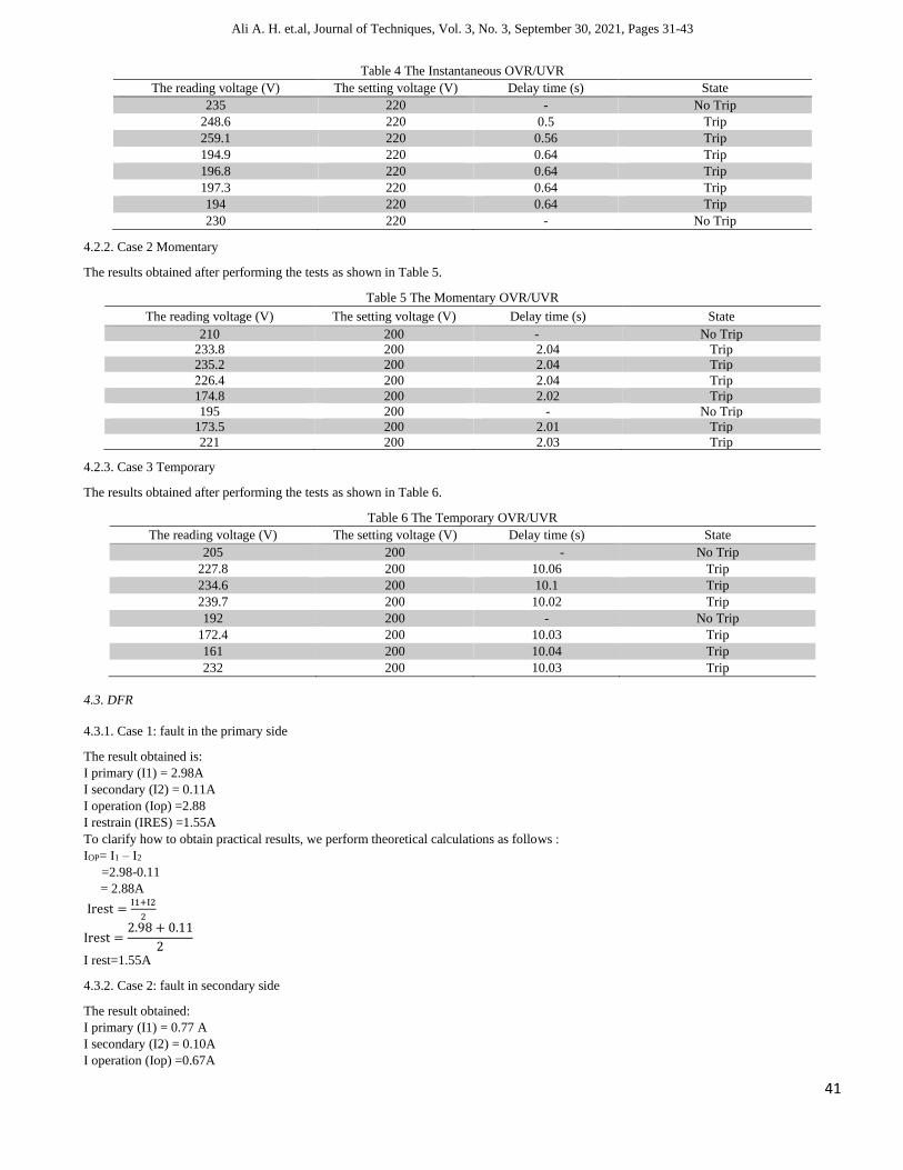
4.2.1. Case 1 Instantaneous
The results obtained after performing the tests as shown in Table 4.
Ali A. H. et.al, Journal of Techniques, Vol. 3, No. 3, September 30, 2021, Pages 31-43
41
Table 4 The Instantaneous OVR/UVR
The reading voltage (V) The setting voltage (V) Delay time (s) State
235 220 - No Trip
248.6 220 0.5 Trip
259.1 220 0.56 Trip
194.9 220 0.64 Trip
196.8 220 0.64 Trip
197.3 220 0.64 Trip
194 220 0.64 Trip
230 220 - No Trip
4.2.2. Case 2 Momentary
The results obtained after performing the tests as shown in Table 5.
Table 5 The Momentary OVR/UVR
The reading voltage (V) The setting voltage (V) Delay time (s) State
210 200 - No Trip
233.8 200 2.04 Trip
235.2 200 2.04 Trip
226.4 200 2.04 Trip
174.8 200 2.02 Trip
195 200 - No Trip
173.5 200 2.01 Trip
221 200 2.03 Trip
4.2.3. Case 3 Temporary
The results obtained after performing the tests as shown in Table 6.
Table 6 The Temporary OVR/UVR
The reading voltage (V) The setting voltage (V) Delay time (s) State
205 200 - No Trip
227.8 200 10.06 Trip
234.6 200 10.1 Trip
239.7 200 10.02 Trip
192 200 - No Trip
172.4 200 10.03 Trip
161 200 10.04 Trip
232 200 10.03 Trip
4.3. DFR
4.3.1. Case 1: fault in the primary side
The result obtained is:
I primary (I1) = 2.98A
I secondary (I2) = 0.11A
I operation (Iop) =2.88
I restrain (IRES) =1.55A
To clarify how to obtain practical results, we perform theoretical calculations as follows :
IOP= I1 – I2
=2.98-0.11
= 2.88A
Irest =I1+I2
2
Irest =2.98 + 0.11
2
I rest=1.55A
4.3.2. Case 2: fault in secondary side
The result obtained:
I primary (I1) = 0.77 A
I secondary (I2) = 0.10A
I operation (Iop) =0.67A

Ali A. H. et.al, Journal of Techniques, Vol. 3, No. 3, September 30, 2021, Pages 31-43
42
I restrain (IRES)=0.43 A
To clarify how to obtain practical results, we perform theoretical calculations as follows :
IOP= I1 – I2
=0.77 -0.10
= 0.67A
Irest =I1+I2
2
Irest =0.77 + 0.10
2
I rest=0.43 A
4.3.3. Case 3: fault out of the zone
I primary (I1) = 0.13 A
I secondary (I2) = 0.17A
I operation (Iop) =0.04A
I restrain (IRES)=0.15 A
To clarify how to obtain practical results, we perform theoretical calculations as follows:
IOP= I1 – I2
=0.17 -0.13
= 0.04A
Irest=(I1+I2)/2
Irest=(0.13+0.17)/2
I rest=0.15 A
After each test, the result show in the TFT screen contains the type of the relay and information about the fault, as shown in Fig. 11.
Fig. 11 The TFT screen of MFR
5. Conclusions
The multi-function relay is a smart relay for easy adjustment of the control signals, with multi-functions (Over Current relay, Over Voltage
/Under Voltage Relay, and Differential Relay) and multi-voltage input built-in. Multifunction relay offers high functionality on a small footprint.
The new design of MFR was built using Arduino from type (MEGA) to work single-phase source that consists of the following types (OCR,
OVR/UVR, DFR). The settings are tuned through the MATLAB GUI environment of the proposed configurations. After each fault, the results
will appear on the MATLAB GUI interface and TFT screen. These features enable result acquisition and setting-control more flexibly.
References
[1] J.C. Das. “Power Systems Protective Relaying,'', Georgia, USA, 2018.
[2] PAITHANKAR, Yeshwant G.; BHIDE, S. R. Fundamentals of power system protection, India, 2010.

Ali A. H. et.al, Journal of Techniques, Vol. 3, No. 3, September 30, 2021, Pages 31-43
43
[3] Sachdev, Mohindar S. “Understanding microprocessor-based technology applied to relaying” Report of Working Group I-01 of the
Relaying Practices Subcommittee ,2009
[4] Birla, Dinesh, Rudra Prakash Maheshwari, and Hari Om Gupta. "Time-overcurrent relay coordination: A review." International Journal of
Emerging Electric Power Systems, Vol 2,2, 2005.
[5] Gan, Zhijun, S. Elangovan, and A. C. Liew. "Microcontroller based overcurrent relay and directional overcurrent relay with ground fault
protection." Electric power systems research Vol38,1, pp.11-17, 1996.
[6] Torres, Francisco, Yofre Jacome, and Charles Henville. "Application of overvoltage protection to the Peruvian power system." ,506-512,
2008.
[7] Miss. Nidhi Reddiwar, and Prof. Pratik Ghutke. "Design and Results of Differential Relay Settings for Power Transformers 80MVA,
40MVA and 100MVA." Int. J. Sci. Eng. Technol. Res 2, Vol 8, pp 32-34, 2019.
[8] Y. L. Goh, A. K. Ramasamy, A. A. Z. Abidin, and F. H. Nagi, “Design of Digital Differential Relay for Protection of Power Transformer”,
International Journal of Emerging Technologies in Science, Technology and Management, Vol 2: Issue 3. 2017
[9] Mozina, Charles, and Michael Young. "Multi-function digital relay commissioning and maintenance testing." IEEE Industry Applications
Magazine Vol 11, pp50-58,2005.
[10] Kezunovic, Mladen, Jinfeng Ren, and Saeed Lotfifard. " Design, Modeling and evaluation of protective relays for power systems. ".
Switzerland: Springer International Publishing, 2016
[11] Deshmukh, M. S., & Barhate, V. T. “Microcontroller based differential relay using fuzzy logic for transformer protection”. In 2017
International Conference on Intelligent Computing and Control Systems (ICICCS), pp. 712-717. IEEE, 2017.
[12] Majumder, R., Dolui, S., Agasti, D., & Biswas, S. “Micro-controller-based overcurrent relay using Hall Effect current sensor”. In 2018
Emerging Trends in Electronic Devices and Computational Techniques (EDCT), pp. 1-4. IEEE, 2018.
[13] Kotb, Mohamed Fawzi, Magdi M. El-Saadawi, and Eman H. El-Desouky. “Design of Over/Under Voltage Protection Relay using Arduino
Uno for FREEDM System”. European Journal of Electrical Engineering and Computer Science, vol. 2, Issue. 7,2018.
[14] Kotb, Mohamed F., Magdi El‐Saadawi, and Eman H. El‐Desouky. “Overcurrent protection relay‐based Arduino Uno for FREEDM
system”. International Transactions on Electrical Energy Systems, vol. 29, Issue. 6,2019.
[15] Rahebi, Javad, and Muhanned Mahmood Shakir Al-Shalah. “Design, Modeling and Implementation of Multi-Function Protective Relay
with Digital Logic Algorithm”. Avrupa Bilim ve Teknoloji Dergisi, vol. 19, pp. 549-565, 2020.
[16] Chen, Zejian. "Advanced microprocessor based intelligent relay for multi-function protection system. ". Diss. Victoria University of
Technology, 1995.
[17] Alstom Grid, ''Network Protection and automation guide, protective Relay, Measurement & control May,2013.
[18] Paul, Manish, Barnali Talukdar, and Banani Baishya. "Simulation of Overvoltage and Under-Voltage Protection in PSIM." International
Journal of Engineering Research & Technology (IJERT), Vol 3, Issue 11, pp 1005-1008, 2014.
[19] Bhosale, G., Vakhare, A., Kaystha, A., Aher, A., & Pansare, V.,"Overvoltage undervoltage protection of electrical equipment".
International Research Journal of Engineering and Technology (IRJET), Vol 5, Issue 2, p.p 29-32., 2018.
[20] Sleva, Anthony M. " Protective relay principles". CRC Press, New york,USA , 2018.
[21] IEEE Power & Energy Society, “IEEE Recommended Practice for Monitoring Electric Power Quality”, IEEE Standardd 1159, New York,
June 2009.
[22] Kumar, N., PrakashVerma, V., Singh, V. K., Nandi, S., & Ventru, V. Double relay-based sag, swell, over and under voltage protection
and detection scheme. In 2013 International Conference on Communication and Signal Processing. IEEE, pp.1008-1012, 2013.
[23] Tripathy, Manoj, Rudra Prakash Maheshwari, and H. K. Verma. "Power transformer differential protection based on optimal probabilistic
neural network." IEEE transactions on power Delivery Vol 25, Issue 1, pp 102-112, 2009.
[24] Kumar, S. D., Raja, P., & Moorthi, S." Self-adaptive differential relaying for power transformers using FPGA". In 2015 International
Conference on Condition Assessment Techniques in Electrical Systems (CATCON) IEEE pp. 121-126, 2015.
[25] Perez, Sandro Gianny Aquiles. "Modeling relays for power system protection studies". Diss. University of Saskatchewan, 2006.
[26] Al-Khalifah, A. K., & El-Saadany, E. F., Investigation of magnetizing inrush current in a single-phase transformer. In 2006 Large
Engineering Systems Conference on Power Engineering, IEEE, pp. 165-171, 2006.