Distributed real time architecture for small biped robot YABIRO
6
Proceedings 2005 IEEE International Symposium on Computational Intelligence in Robotics and Automation June 27-30, 2005, Espoo, Finland Distributed real time architecture for small biped robot YABIRO. M. Albero, F. Blanes, G. Benet, P. Perez, J.E. Simo, J. Coronel Departamenito de Informatica de Sistemas y Computadores. (DISCA) UniversidadPolit&nica de Valencia. Camino de Vera sln Valencia, Spain mialgildoctor.upv.es, {pblanes,gbenet,pperez,jsimo}@disca.up.es, jocopa(doctor.upv.es Abstract - In this paper we present a real time architecture for embedded control systems to be used in a mobile biped robot called YABIRO'. The robot has a total of 14 degrees of freedom (DOF). This number of joints enables YABIRO to produce many different gait configurations, and is also suitable to test and validate the proposed real time control architecture. A new embedded intelligent motor controller (IMCD) has been also designed and implemented in each joint node of the distributed architecture, to work inside the real time network. Index Terms- embedded systems, humanoid robots, distributed control systems. I. INTRODUCTION One of the most exciting research areas inside field of mobile robotics is the bipedal locomotion problem. A decade ago, the number of research groups in bipedal locomotion was very small; only a few laboratories, like Honda [1], AIST- Waseda [2], etc. had a mechanical robot structure where to execute their proposed algorithms. If we look over all the different designs around the world today we could see the increase of these research groups whose focus their investigations in different areas of bipedal walking. Today we can find a great number of different robots architectures, like the most sophisticated designs ASIMO [3], HRP-2 [4], QRIO [5], and so on. These robots have been implemented with the best mechanical materials and accurately mechanized parts actuators and sensors have been specially designed for the robot distributed control architecture, as well as many other expensive features. The other group of bipedal architectures have been developed for small and cheap bipeds robots. Some of these robots have been described in Pino [6], Wasedanian [7], Rope [8], etc. Main features of these robots are the low cost 1 YABIRO stands for Yet Another BIped RObot, and is currently being developed with funds from the projects DPI 2002-04434-C04-03 from Spanish FEDER-CICYT, and the GV04B-392. platform, where they use a commercial and cheap cost pieces, like servomotors, cheap sensors, and common materials for the mechanical platform. Fig. 1: YABIRO walking In the last few years the number of new robot designs has been increased, because it is a good way to obtain a reliable biped robot platform to develop and study new control architectures with reduced cost and maintenance. The main problem of these robots is the poor performance of their control architecture due to the fact that their actuators (servos) haven't got any feedback of their state, and the only communication between the control board and the servo nodes are analog servo cables instead of a digital communications bus. It is expected in the next years that this type of biped robots will improve many of their actual features by using smart, embedded nodes and distributed control architectures around real-time bus communications. In this paper, some preliminary results of our research in the field of distributed real time control architectures are described, applied to biped robot YABIRO [9], our low cost biped robot platform. This research has been focused to improve the real-time communications between all the actuators, sensors and control boards inside YABIRO, using the CAN bus. This means to obtain a small, low-cost biped robot platform with a powerful distributed control architecture 0-7803-9355-4 / 05 / $20.00 ©2005 IEEE. 653
Transcript of Distributed real time architecture for small biped robot YABIRO
Proceedings 2005 IEEE International Symposium onComputational Intelligence in Robotics and AutomationJune 27-30, 2005, Espoo, Finland
Distributed real time architecture for small biped robotYABIRO.
M. Albero, F. Blanes, G. Benet, P. Perez, J.E. Simo, J. CoronelDepartamenito de Informatica de Sistemas y Computadores. (DISCA)
UniversidadPolit&nica de Valencia.Camino de Vera sln Valencia, Spain
mialgildoctor.upv.es, {pblanes,gbenet,pperez,jsimo}@disca.up.es, jocopa(doctor.upv.es
Abstract - In this paper we present a real timearchitecture for embedded control systems to be used in amobile biped robot called YABIRO'. The robot has a totalof 14 degrees of freedom (DOF). This number of jointsenables YABIRO to produce many different gaitconfigurations, and is also suitable to test and validate theproposed real time control architecture. A new embeddedintelligent motor controller (IMCD) has been alsodesigned and implemented in each joint node of thedistributed architecture, to work inside the real timenetwork.
Index Terms- embedded systems, humanoid robots, distributedcontrol systems.
I. INTRODUCTION
One of the most exciting research areas inside field ofmobile robotics is the bipedal locomotion problem. A decadeago, the number of research groups in bipedal locomotion wasvery small; only a few laboratories, like Honda [1], AIST-Waseda [2], etc. had a mechanical robot structure where toexecute their proposed algorithms. If we look over all thedifferent designs around the world today we could see theincrease of these research groups whose focus theirinvestigations in different areas of bipedal walking.
Today we can find a great number of different robotsarchitectures, like the most sophisticated designs ASIMO [3],HRP-2 [4], QRIO [5], and so on. These robots have beenimplemented with the best mechanical materials andaccurately mechanized parts actuators and sensors have beenspecially designed for the robot distributed controlarchitecture, as well as many other expensive features.
The other group of bipedal architectures have beendeveloped for small and cheap bipeds robots. Some of theserobots have been described in Pino [6], Wasedanian [7], Rope[8], etc. Main features of these robots are the low cost
1 YABIRO stands for Yet Another BIped RObot, and iscurrently being developed with funds from the projects DPI2002-04434-C04-03 from Spanish FEDER-CICYT, and theGV04B-392.
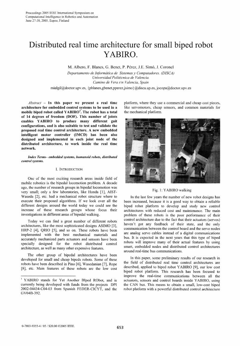
platform, where they use a commercial and cheap cost pieces,like servomotors, cheap sensors, and common materials forthe mechanical platform.
Fig. 1: YABIRO walking
In the last few years the number of new robot designs hasbeen increased, because it is a good way to obtain a reliablebiped robot platform to develop and study new controlarchitectures with reduced cost and maintenance. The mainproblem of these robots is the poor performance of theircontrol architecture due to the fact that their actuators (servos)haven't got any feedback of their state, and the onlycommunication between the control board and the servo nodesare analog servo cables instead of a digital communicationsbus. It is expected in the next years that this type of bipedrobots will improve many of their actual features by usingsmart, embedded nodes and distributed control architecturesaround real-time bus communications.
In this paper, some preliminary results of our research inthe field of distributed real time control architectures aredescribed, applied to biped robot YABIRO [9], our low costbiped robot platform. This research has been focused toimprove the real-time communications between all theactuators, sensors and control boards inside YABIRO, usingthe CAN bus. This means to obtain a small, low-cost bipedrobot platform with a powerful distributed control architecture
0-7803-9355-4 / 05 / $20.00 ©2005 IEEE. 653
where all the robot joints feedback signals. the actual state olall nodes, etc., can be transmitted without any jitter.
The final goal of this designi is to produce a roboticplatformn that can be used to design and test new controlarchitectures, vision systems, humanoid behaviour, etc, andalso to create an accessible platform for students. Therefore,to test all these final goals and create a simplified robot modelwe have implemented an easy and intuitive system controlarchitecture, based on ZMP control [10]
This paper is organized as follows. An outline of theYABIRO layout is given in Section 2 Hardware of thedistribute architecture is commented in section 3. The realtime commnunications protocol is shown and described insection 4. The main control platform is explained in thesection 5. Finally, experimental results and conclusions areshowni in sections 6 and 7 respectively.
IL. YABIRO DESCRIPTION.
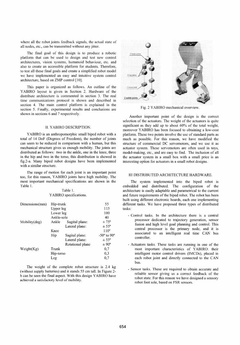
YABIRO is an anthropomorphic small biped robot with atotal of 14 DoF (Degrees of Freedom), the number of jointscan seem to be reduced in comparison with a human, but thismechanical structure gives us enough mobility. The joints aredistributed as follows: two in the ankle, one in the knee, threein the hip and two in the torso, this distribution is showed infig.2-a. Many biped robot designs have been implementedwith a similar structuLre.
The range of motion for each joint is an inlportant pointtoo, for this reason, YABIRO joints have high mobility. Themost important mechanical specifications are shown in theTable I
Table I.YABIRO specifications.
Dimensions(mm)
Mobility(deg)
Hip-trunkUpper legLower legAnkle-soleAnkle Sagital plane.
Lateral planetKneeHip
Weight(Kg)
Sagital plane:Lateral plane:Rotational plane
TrunkHip-torsoLeg
11510040
.1c}±550I Il0c
-(0? to 900±; 550
90"9
0.307
The weight of the complete robot structure is 2.4 kg(without supply batteries) and it stands 55 cm tall. In Figure 2-b can be seen the final aspect. With this design YABIRO haveachieved a satisfactory level of mobilitv.
Fig. 2 YABIRO mechanical overviexw.
Another important point of the desigin is the correctselection of the actuators. The weight of the actuators is quitesignificant as they add up to about 6000 of the total weight,moreover YABIRO has been focused to obtaining a low-costplatform. These two points involve the use of standard parts as
much as possible. For this reason, we have modified thestructure of commercial DC servomotors. and we use it as
actuator system. These servomotors are often used in toys,model-making, etc. and are easy to find. The inclusion of allthe actuator system in a small box with a small price is an
interesting option for actuators in a small robot designs,
III DISTRIBUTED ARCHITECTURE H4ARDWARE.
The system implemented into the biped robot isembedded and distributed. The configuration of thearchitecture is easily adaptable and parametrical to the currentand future requirements of the biped robot. The robot has beenbuilt using different electronic boards, each one inmplementingdifferent tasks. We have proposed three types of distributedtasks:
Control tasks. In the architecture there is a centralprocessor dedicated to trajectory generation, sensor
fusion and high level goal planning and control. Thiscentral processor is the primarv node, and it isassociated to an intelligent real time C.AN buscontroller,
Actuators tasks. These tasks are running in one of themost important characteristics of YABIRO theirintelligent motor control drivers (IMCDs). placed ineach robot joint and directly connected to the CANbus.
- Sensor tasks. These are required to obtain accurate andreliable sensor giving us a correct feedback of therobot state. For this reason we have designed a sensoryrobot foot sole, based on FSR sensors.
654
A. Bus control board.
Together with the main embedded Trasmeta Crusoecontrol board, a new intelligent PC104-CAN controller boardhas been designed and included into the main node. Thisadditional board has been designed to manage a real timeCAN protocol without intervention of the main control board.This board has two main tasks, first is to adapt all the inputmessages from the embedded-PC to a TDMA-CAN bus. Thismeans that the CAN controller board uses a previouslyprogrammed messages time table to send all the CANmessages in their correct time window.
The second task of this CAN board is to guarantee andcontrol the timing correctness for all the time slots on the bus.For this task all the nodes must be previously loaded with anupdated time table. Since the bus starts in time-triggered modethe bus control board manages all the starting procedures ineach node.
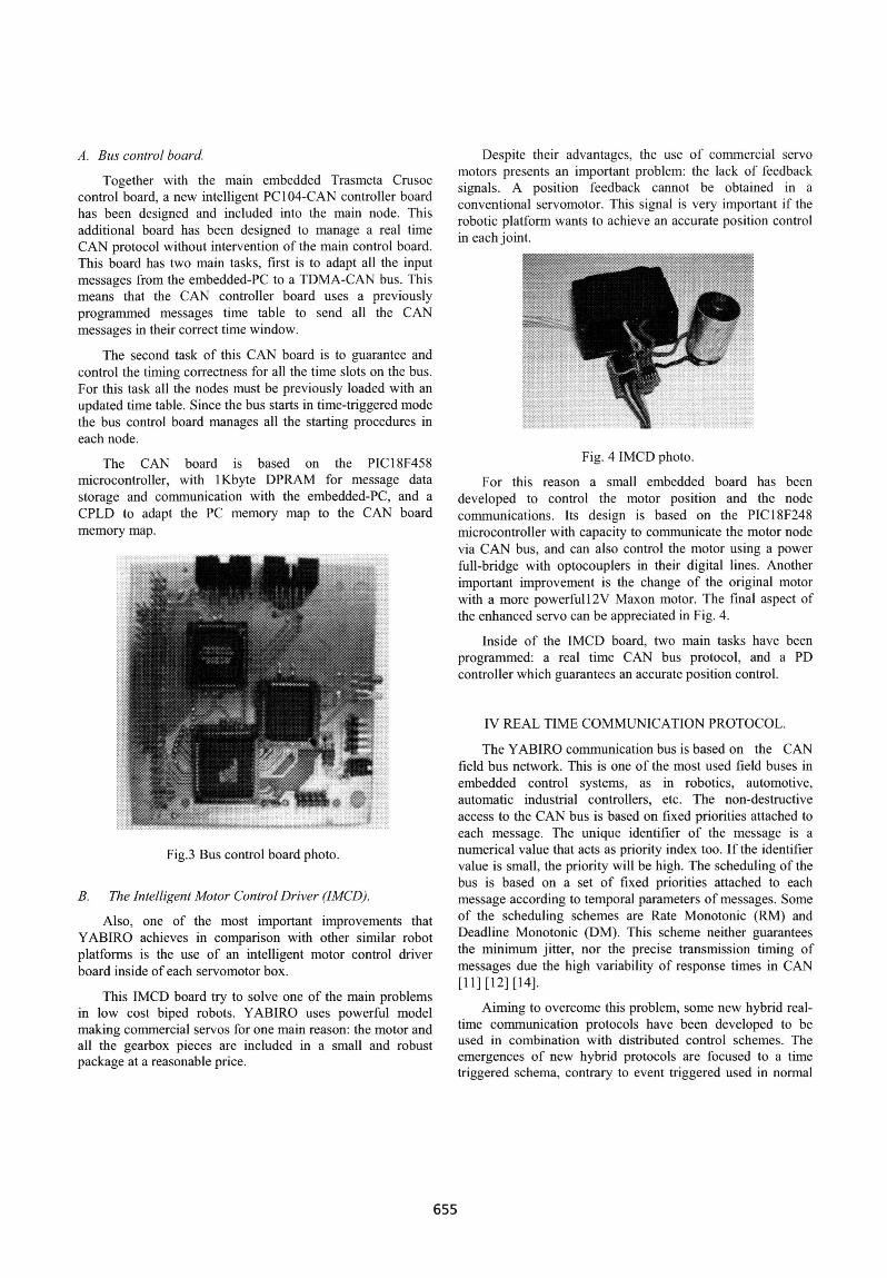
The CAN board is based on the PIC18F458microcontroller, with lKbyte DPRAM for message datastorage and communication with the embedded-PC, and aCPLD to adapt the PC memory map to the CAN boardmemory map.
Fig.3 Bus control board photo.
B. The Intelligent Motor Control Driver (IMCD).
Also, one of the most important improvements thatYABIRO achieves in comparison with other similar robotplatforms is the use of an intelligent motor control driverboard inside of each servomotor box.
This IMCD board try to solve one of the main problemsin low cost biped robots. YABIRO uses powerful modelmaking commercial servos for one main reason: the motor andall the gearbox pieces are included in a small and robustpackage at a reasonable price.
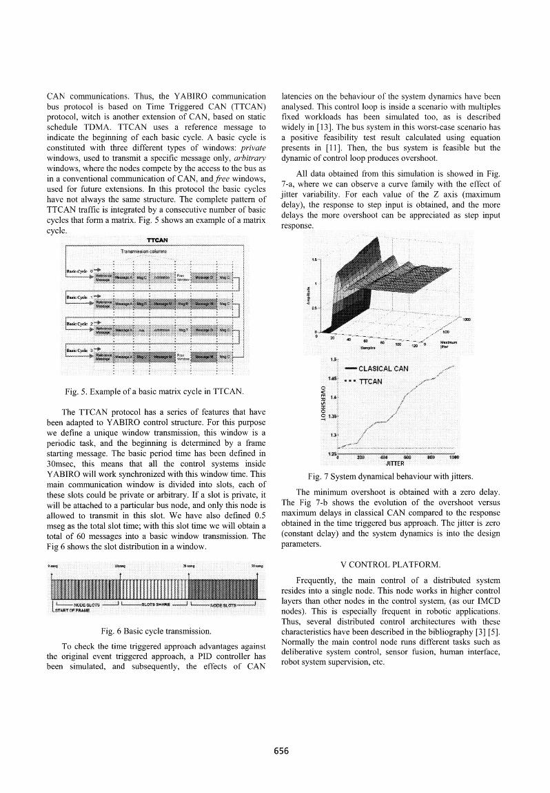
Despite their advantages, the use of commercial servomotors presents an important problem: the lack of feedbacksignals. A position feedback cannot be obtained in aconventional servomotor. This signal is very important if therobotic platform wants to achieve an accurate position controlin each joint.
Fig. 4 IMCD photo.
For this reason a small embedded board has beendeveloped to control the motor position and the nodecommunications. Its design is based on the PIC18F248microcontroller with capacity to communicate the motor nodevia CAN bus, and can also control the motor using a powerfull-bridge with optocouplers in their digital lines. Anotherimportant improvement is the change of the original motorwith a more powerfull2V Maxon motor. The final aspect ofthe enhanced servo can be appreciated in Fig. 4.
Inside of the IMCD board, two main tasks have beenprogrammed: a real time CAN bus protocol, and a PDcontroller which guarantees an accurate position control.
IV REAL TIME COMMUNICATION PROTOCOL.
The YABIRO communication bus is based on the CANfield bus network. This is one of the most used field buses inembedded control systems, as in robotics, automotive,automatic industrial controllers, etc. The non-destructiveaccess to the CAN bus is based on fixed priorities attached toeach message. The unique identifier of the message is anumerical value that acts as priority index too. If the identifiervalue is small, the priority will be high. The scheduling of thebus is based on a set of fixed priorities attached to eachmessage according to temporal parameters of messages. Someof the scheduling schemes are Rate Monotonic (RM) andDeadline Monotonic (DM). This scheme neither guaranteesthe minimum jitter, nor the precise transmission timing ofmessages due the high variability of response times in CAN[11] [12] [14].
Aiming to overcome this problem, some new hybrid real-time communication protocols have been developed to beused in combination with distributed control schemes. Theemergences of new hybrid protocols are focused to a timetriggered schema, contrary to event triggered used in normal
655
CAN communications. Thus, the YABIRO communicationbus protocol is based on Time Triggered CAN (TTCAN)protocol, witch is another extension of CAN, based on staticschedule TDMA. TTCAN uses a reierence message toindicate the beginning of each basic cycle. A basic cycle isconstituted with three different types of windoxxws: pi-ivctewindows, used to transmit a specific message only. arbitrai-vwindows, where the nodes compete by the access to the bus asin a conventional communication of CAN, and fiee windows,used -for future extensions. In this protocol the basic cycleshave not always the same structure. The complete pattern ofTTCAN traffic is integrated by a consecutive number of basiceycles that form a matrix. Fig. 5 shows an example of a matrixcycle.
TTGAN...Tronmsnass.on c...n..s
v ~ ~ ~ ~ ~ ~ ~ ~ ~ ~ ....
~~fRuw44. 2.5
ig Example of a basic matrix cycle in TC N.
The TTCAN protocol has a senes o1 features that havebeen adapted to YABIRO control structure. For this purposewe define a unique window transmission, this window is a
periodic task, and the beginning is determined by a framestarting message. The basic period time has been defined in30msec, this means that all the control. systems insideYABIRO will work synchronized with this window time. Thi-smain communication window is divided into slots, each ofthese slots could be private or arbitrary. If a slot is pnxvate, itwill be attached to a particular bus node. and only this node isallowed to transmit in this slot. We havc also defined 0.5mseg as the total slot time; with this slot time we will obtain atotal of 60 mnessages into a basic window transmission. TheFig 6 shows the slot distribution in a window.
Fig. 6 Basic cycle transmission.
To check the time triggered approach advantages againstthe original event triggered approach, a PID controller hasbeen simulated, and subsequently. the etfects of CAN
latencies on the behaviour of the system dynamics have beenanalysed. This control loop is inside a scenario with multiplesfixed workloads has been simulated too. as is describedwidely in [ 13]. The bus system in this worst-case scenario hasa positive feasibility test result calculated using equationpresents in [11]. Then, the bus system is feasible but thedynamic of control loop produces overshoot.
All data obtained from this simulation is showed in Fig7-a, where we can observe a curve family with the effect ofjitter variability. For each value of the Z axis (maximum)delay), the response to step input is obtained, and the moredelays the more overshoot can be appreciated as step inpulresponse.
Ii10
g
o 310w
r'- $00.; o
Maxt:§nsmaqe,s 20 jitor
-CLASICAL CAN
8X 1sTTCAN=
0H s:.:1:l' 9~~~~~~~~~~~~~~~~~~~~~~~~~C
,
0 020. Ot .0NJITTER
P1 j1J
Fig. 7 System dynamical behaxviour with jitters.
The minimum overshoot is obtained with a zero delayvThe Fig 7-b shows the evolution of the overshoot versusmaximum delays in classical CAN compared to the responseobtained in the time triggered bus approach. The jitter is zero(constant delay) and the system dynamics is into the desigRnparameters.
V CONTROL PLATFORM.
Frequently, the main control of a distributed systemresides into a single node. This node works in higher controllayers than other nodes in the control system, (as our IMCDnodes). This is especially frequent in robotic applications.Thus, several distributed control architectures with thesecharacteristics have been described in the bibliography [3] [5].Normally the main control node runs different tasks such asdeliberative system control, sensor fusion, human interface,robot system supervision, etc.
656
l
OJ Sam
f-.-
To carry out some of these tasks, YABIRO includes amulti-tasking real time control platform, based on a TransmetaCrusoe processor board, where RTLinux 3.0 real time kernelis running. The use of this kernel together with a Linux 2.4.18kernel, makes possible the division between critical tasks andother tasks into the same control system. For this reason wehave used a layered distribution based on different taskrequirements. YABIRO runs a great number of differenttasks, with different time restrictions and periodicity.
A schema with this layer distribution is shown in Fig. 8,where the three main layers of YABIRO can be observed.The top layer is the decision layer, where non real time tasks,like path planning, behavior, and human interaction tasks canbe executed. The decision layer is implemented into theLinux kernel. The middle layer or RT layer has beenimplemented in RTLinux. In this layer, real time tasks, suchas control task, robot path generation, sensor data fusion, etc.,can be executed. Finally the lower layer, named local layer, ismade up for all the distributed nodes in the robot.
..........
-: .- AMi D'VQNN8CRT-LNX
Fig. 8 Control layer distribution.
Scalability and modularity are some of the main featuresof YABIRO control structure. To emphasize this idea, the RTlayer implements different tasks across the RTLinux modules.Different set of advantages can be obtained using thisprogramming model. Among others, dynamically loading ofmodules, the use of real time tools for modulescommunication, or a modular and scalable system, can becited.
The Robot Reference Interpretation (RRI), is the taskresponsible of passing correctly all the informnation from anymodule of RTLayer into a communication package, with itscomplete identifier information. RRI is a 30 msec periodictask that is synchronized with the window transmission busperiod. The Network task controls all the input-outputmessages, and manages the bus control board. FinallyTrajectory Generator task and Control task are periodic tasks,which are synchronized with a RRI task. All these tasksimplement a control architecture based on inverted pendulummodel control (IPMC) [10].
Actually the RTLayer in YABIRO can manage a, set ofdifferent tasks, like a RRI task, Trajectory Generator, Controltask and Network Communication task (each one of them asan independent module). The communication between all
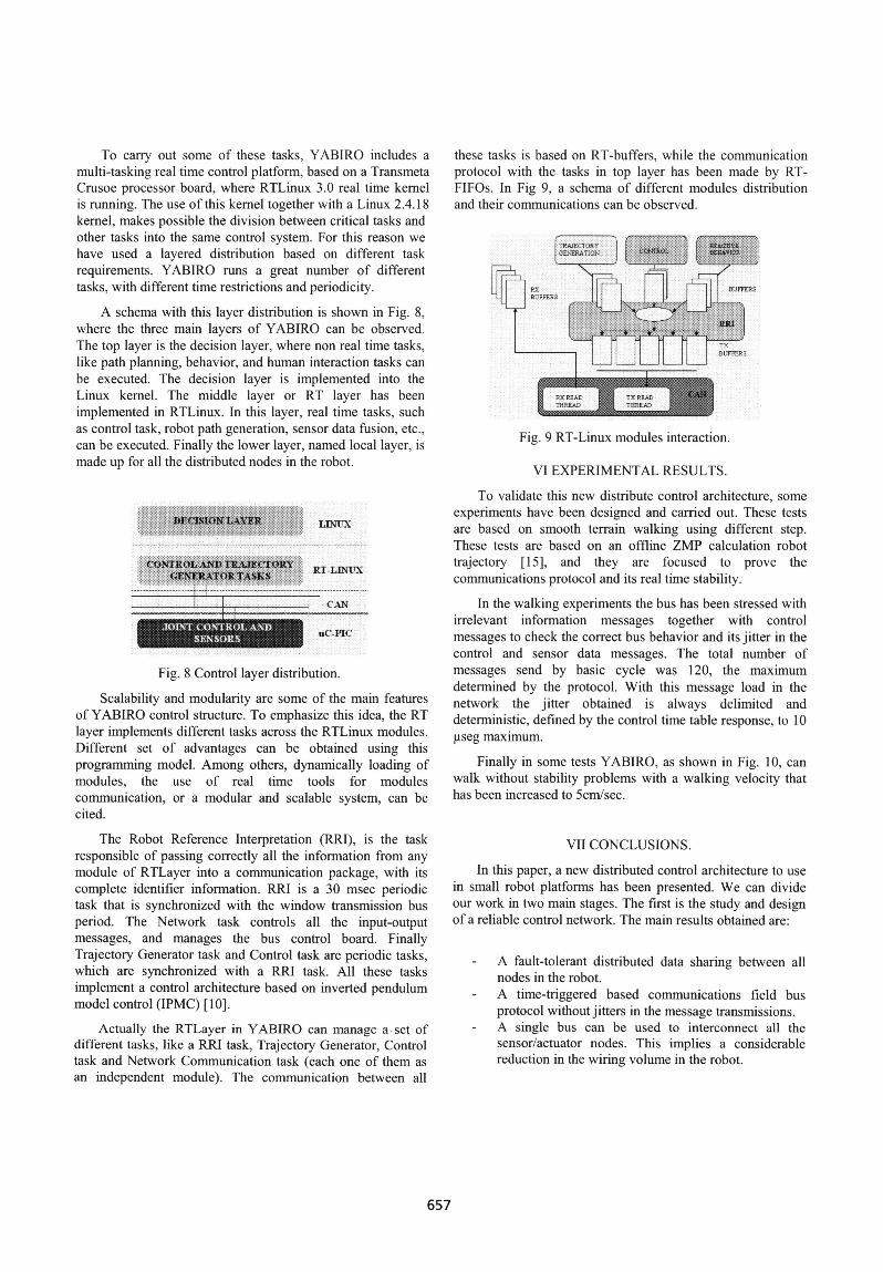
these tasks is based on RT-buffers, while the communicationprotocol with the tasks in top layer has been made by RT-FIFOs. In Fig 9, a schema of different modules distributionand their communications can be observed.
'TRAJECTORY:,-GENERATIO
il :BUUR; i[f-- I0 | F FERS-BU FFERS~~ ~~~~~~BFER
:TXBUFFERS
Fig. 9 RT-Linux modules interaction.
VI EXPERIMENTAL RESULTS.
To validate this new distribute control architecture, someexperiments have been designed and carried out. These testsare based on smooth terrain walking using different step.These tests are based on an offline ZMP calculation robottrajectory [15], and they are focused to prove thecommunications protocol and its real time stability.
In the walking experiments the bus has been stressed withirrelevant information messages together with controlmessages to check the cor-rect bus behavior and its jitter in thecontrol and sensor data messages. The total number ofmessages send by basic cycle was 120, the maximumdetermined by the protocol. With this message load in thenetwork the jitter obtained is always delimited anddeterministic, defined by the control time table response, to 10giseg maximum.
Finally in some tests YABIRO, as shown in Fig. 10, canwalk without stability problems with a walking velocity thathas been increased to 5cm/sec.
VII CONCLUSIONS.
In this paper, a new distributed control architecture to usein small robot platforms has been presented. We can divideour work in two main stages. The first is the study and designof a reliable control network. The main results obtained are:
- A fault-tolerant distributed data sharing between allnodes in the robot.
- A time-triggered based communications field busprotocol without jitters in the message transmissions.
- A single bus can be used to interconnect all thesensor/actuator nodes. This implies a considerablereduction in the wiring volume in the robot.
657
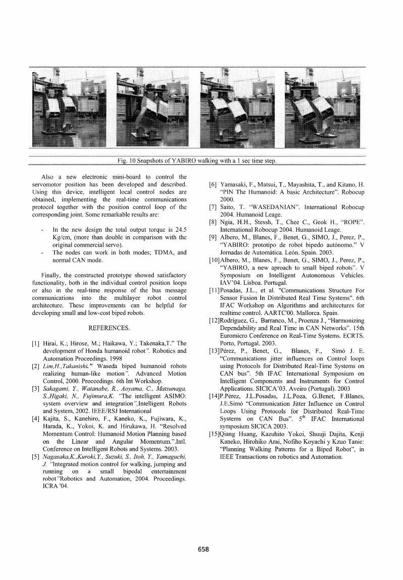
Fig. 10 Snapshots of YABIRO walking with a I sec time step."....fMsI--*-"",^N>$s.tt-.,.r .^u. ;Kz.v
Also a new electronic mini-board to control theservomotor position has been developed and described.Using this device, intelligent local control nodes areobtained, implementing the real-time communicationsprotocol together with the position control loop of thecorresponding joint. Some remarkable results are:
- In the new design the total output torque is 24.5Kg/cm, (more than double in comparison with theoriginal commercial sen o).
- The nodes can work in both modes; TDMA, andnormal CAN mode.
Finally, the constructed prototype showed satisfactoryfunctionality, both in the individual control position loopsor also in the real-time response of the bus messagecommunications into the multilayer robot controlarchitecture. These improvements can be helpful fordeveloping small and low-cost biped robots.
REFERENCES.
[1] Hirai, K., Hirose, M.; Haikawa, Y. Takenaka,T.' Thedevelopment of Honda humanoid robot ". Robotics andAutomation Proceedings. 1998
[2] Lim,H.,Takanishi." Waseda biped humanoid robotsrealizing human-like motion". Advanced MotionControl, 2000. Proceedings. 6th Int Workshop.
[3] Sakagani, Y Watanabe, R. Aovama, C. Matsunaga,S.,Higaki, FujimuraK. "The intelligent ASIMOsystem overview and integration' Intelligent Robotsand System, 2002. IEEE/RSJ International
[4] Kajita, S., Kanehiro, F., Kaneko, K, Fujiwara, K.,Harada. K., Yokoi, K. and Hirukawa, H. "ResolvedMomentum Control: Humanoid Motion Planning basedon the Linear and Angular Momentum.".Intl.Conference on Intelligent Robots and Systems. 2003.
[5] Nagasaka,K.,Kuroki, Y., Suzuki, S., Itoh. Y, Yaniaguchi,""Integrated motion control for walking, jumping and
running on a small bipedal entertainmentrobot "Robotics and Automation, 2004 Proceedings.ICRA '04
[6] Yamasaki, F., Matsui, T., Mayashita, T., and Kitano, H."PIN The Humanoid: A basic Architecture". Robocup2000.
[7] Saito, T. 'WASEDANIAN'. International Robocup2004. Humanoid Leage.
[8] Ngia, H.H., Stessh, T.. Chee C., Geok H., -ROPEIIntemational Robocup 2004. Humanoid Leage.
[9] Albero, M., Blanes, F., Benet, G., SIMO, J1. Perez P,"'YABIRO: prototipo de robot bipedo autonomo,"' 'V'Jomadas de Automatica. Le6n. Spain. 20035
[lO]Albero, M., Blanes, F., Benet, G.. SIMO, J., Perez. P.,"YABIRO, a new aproach to small biped robots". VSymposium on Intelligent Autonomous Vehicles,IAV'04. Lisboa. Portugal.
[I l]Posadas, J.L., et al. "Communications Structure ForSensor Fusion In Distributed Real Time Systems'. 6thIFAC Workshop on Algorithms and architectures forrealtime control. AARTC'00. Mallorca. Spain.
[I 2]Rodriguez, G., Barranco, M., Proenza J., "HarmonizingDependability and Real Time in CAN Netwvorks'. 15thEuromicro Conference on Real-Time Systems. ECRTS,Porto, Portugal. 2003.
[13]Perez, P., Benet. G., Blanes, F., Simo J. E."Communications jitter influences on Control loopsusing Protocols for Distributed Real-Time Systems onCAN bus"'. 5th IFAC Intemational Symposium onIntelligent Components and Instruments for ControlApplications. SICICAO03. Aveiro (Portugal). 2003
[14]P.P6rez, J.L.Posadas, J.L.Poza, G.Benet, F.Blanes,J.E.Sim6 "'Communication Jitter Influence on ControlLoops Using Protocols for Distributed Real-TimeSystems on CAN Bus". 5th IFAC Intermationalsymposium SICICA 2003.
[1 5]Qiang Huang, Kazuhito Yokoi, Shuuji Dajita, KenjiKaneko, Hirohiko Arai, Nofiho Koyachi y Kzuo Tanie"Planning Walking Pattems for a Biped Robot'. inIEEE Transactions on robotics and Automation,
658