A control architecture with stabilizer for 3D stable dynamic walking of SHERPA biped robot on...
6
A Control Architecture With Stabilizer For 3D Stable Dynamic Walking of SHERPA Biped Robot on Compliant Ground A. Chemori, S. Le Floch, S. Krut and E. Dombre Abstract— This paper deals with design and implementa- tion of a control architecture for 3D dynamic walking with foot/ground compliant contact. This architecture includes a ZMP-based pattern generator, a computed torque controller based on the reduced order dynamics of the system, and a stabilizer to enhance the stability robustness of the control architecture. The effectiveness of the proposed control archi- tecture is shown through numerical simulations. I. INTRODUCTION AND RELATED WORKS Legged robots are those mechanical structures which are able to move on ground by alternating support legs. The problem of control of such robots is more complex than the case of classical robot manipulators with a fixed base, inasmuch as the legs are not attached to the ground and consequently they can lift off during movement. Further- more, control of legged robots should take into account stability of the whole structure of the robot during walking. Most successful legged robots have 2 (biped), 4 (quadrupeds) or 6 (hexapods) legs. This legs-over-wheels approach lends itself for use in all-terrain purposes seeing as legs are more effective in an uneven ground than wheels. One interesting class of legged robots is biped walking robots where mainly two sub-classes are studied, namely 2D and 3D biped robots. In biped walking locomotion, two gaits could be underlined. Static walking which refers to a system that stays balanced by always keeping the center of mass (COM) of the system vertically projected over the polygon of support formed by feet. On the contrary, dynamic walking is not constrained in such a manner, therefore the COM may leave the support polygon for periods of time. When interesting in 3D biped walking robots, many control approaches have been proposed to resolve the problem of locomotion control. The basic control architecture in this context includes mainly three components, namely the tra- jectory generator, the controller and the stabilizer. The classical way to deal with stable trajectories generation is to use the concept of Zero Moment Point (ZMP) [2] [5] [19]. However, other criteria have also been proposed, such as the Contact Wrench Sum (CWS) [9] or the Foot Rotation Indicator (FRI) [16]. The aim of the second component is to track reference trajectories, generated by the pattern generator. Within this framework, many control approaches have been proposed in the literature. A classical Proportional Derivative (PD) con- troller has been proposed in [8] to control HanSaRam-VII, A. Chemori, S. Le Floch, S. Krut, and E. Dombre are with LIRMM, Univ. Montpellier 2 - CNRS, 161 rue Ada, 34392 Montpellier, France [email protected] a 27 degrees of freedom (dof) 3D biped walking robot. In [1], the problem of control of BIP, a 15 dof 3D biped walking robot is resolved through a nonlinear predictive control scheme with constraints. In [3], a 12 dof 3D biped walking robot has been controlled thanks to an optimal controller. In [15], an impedance control has been proposed to control a 12 dof 3D biped robot in simulation, while in [14], the same authors have proposed a hybrid control architecture based on an impedance control and computed torque control for the same application. A feedforward PID controller has been proposed in [6] to deal with walking control of Pneumat-BT, a 3D 13 dof biped robot with 26 artificial muscles. Even if these controllers are not the only ones used in 3D biped robot control, they highlight the diversity of the proposed solutions in term of control schemes. In order to improve the performance and robustness of the controller with respect to numerical errors and external perturbations, the control architecture needs an outer control loop, this is achieved through the stabilizer. The stabilization could be performed at different levels by modifying trajec- tories either in joint space, in operational space, or in both. In joint space, one solution chosen to stabilize the posture of the 12 dof robot WL-10RD was to modify the ankle joints’ trajectories of the support leg [20]. An other solution is that proposed in [10], where the idea was to update the hip’s trajectory. In operational space, one of the original ideas, is that of Raibert [17], where the author has proposed to modify the feet’s trajectories to change landing position such that the stability and the behavior of a hopping robot is improved. This idea was reproduced in [4] on P2 Honda robot, where the authors have proposed a complex control architecture including different stabilizers (body inclination control, ZMP control, and ground reaction force control) as well as the Raibert’s foot landing controller. In this paper, a control architecture (cf. figure 5) is proposed for a 3D biped walking robot nicknamed SHERPA, to deal with stable dynamic walking control. Simulation results are presented to illustrate the effectiveness of the proposed control architecture through the obtained biped walking on horizontal compliant ground. The paper is organized as follows: In section II, the prototype of SHERPA robot is introduced as well as its different mathematical models (kinematics and dynamics), the com- pliant contact model is also introduced and discussed in this section. In section III, the proposed control architecture is introduced where its components (pattern generator, con- troller, and stabilizer) are detailed. Section IV is devoted 2010 IEEE-RAS International Conference on Humanoid Robots Nashville, TN, USA, December 6-8, 2010 978-1-4244-8689-2/10/$26.00 ©2010 IEEE 480
-
Upload
univ-montp2 -
Category
Documents
-
view
1 -
download
0
Transcript of A control architecture with stabilizer for 3D stable dynamic walking of SHERPA biped robot on...

A Control Architecture With Stabilizer For 3D Stable Dynamic
Walking of SHERPA Biped Robot on Compliant Ground
A. Chemori, S. Le Floch, S. Krut and E. Dombre
Abstract— This paper deals with design and implementa-tion of a control architecture for 3D dynamic walking withfoot/ground compliant contact. This architecture includes aZMP-based pattern generator, a computed torque controllerbased on the reduced order dynamics of the system, and astabilizer to enhance the stability robustness of the controlarchitecture. The effectiveness of the proposed control archi-tecture is shown through numerical simulations.
I. INTRODUCTION AND RELATED WORKS
Legged robots are those mechanical structures which are
able to move on ground by alternating support legs. The
problem of control of such robots is more complex than
the case of classical robot manipulators with a fixed base,
inasmuch as the legs are not attached to the ground and
consequently they can lift off during movement. Further-
more, control of legged robots should take into account
stability of the whole structure of the robot during walking.
Most successful legged robots have 2 (biped), 4 (quadrupeds)
or 6 (hexapods) legs. This legs-over-wheels approach lends
itself for use in all-terrain purposes seeing as legs are more
effective in an uneven ground than wheels. One interesting
class of legged robots is biped walking robots where mainly
two sub-classes are studied, namely 2D and 3D biped robots.
In biped walking locomotion, two gaits could be underlined.
Static walking which refers to a system that stays balanced
by always keeping the center of mass (COM) of the system
vertically projected over the polygon of support formed by
feet. On the contrary, dynamic walking is not constrained in
such a manner, therefore the COM may leave the support
polygon for periods of time.
When interesting in 3D biped walking robots, many control
approaches have been proposed to resolve the problem of
locomotion control. The basic control architecture in this
context includes mainly three components, namely the tra-
jectory generator, the controller and the stabilizer.
The classical way to deal with stable trajectories generation
is to use the concept of Zero Moment Point (ZMP) [2] [5]
[19]. However, other criteria have also been proposed, such
as the Contact Wrench Sum (CWS) [9] or the Foot Rotation
Indicator (FRI) [16].
The aim of the second component is to track reference
trajectories, generated by the pattern generator. Within this
framework, many control approaches have been proposed in
the literature. A classical Proportional Derivative (PD) con-
troller has been proposed in [8] to control HanSaRam-VII,
A. Chemori, S. Le Floch, S. Krut, and E. Dombre are with LIRMM,Univ. Montpellier 2 - CNRS, 161 rue Ada, 34392 Montpellier, [email protected]
a 27 degrees of freedom (dof) 3D biped walking robot. In
[1], the problem of control of BIP, a 15 dof 3D biped
walking robot is resolved through a nonlinear predictive
control scheme with constraints. In [3], a 12 dof 3D biped
walking robot has been controlled thanks to an optimal
controller. In [15], an impedance control has been proposed
to control a 12 dof 3D biped robot in simulation, while
in [14], the same authors have proposed a hybrid control
architecture based on an impedance control and computed
torque control for the same application. A feedforward PID
controller has been proposed in [6] to deal with walking
control of Pneumat-BT, a 3D 13 dof biped robot with
26 artificial muscles. Even if these controllers are not the
only ones used in 3D biped robot control, they highlight
the diversity of the proposed solutions in term of control
schemes.
In order to improve the performance and robustness of
the controller with respect to numerical errors and external
perturbations, the control architecture needs an outer control
loop, this is achieved through the stabilizer. The stabilization
could be performed at different levels by modifying trajec-
tories either in joint space, in operational space, or in both.
In joint space, one solution chosen to stabilize the posture of
the 12 dof robot WL-10RD was to modify the ankle joints’
trajectories of the support leg [20]. An other solution is that
proposed in [10], where the idea was to update the hip’s
trajectory. In operational space, one of the original ideas, is
that of Raibert [17], where the author has proposed to modify
the feet’s trajectories to change landing position such that the
stability and the behavior of a hopping robot is improved.
This idea was reproduced in [4] on P2 Honda robot, where
the authors have proposed a complex control architecture
including different stabilizers (body inclination control, ZMP
control, and ground reaction force control) as well as the
Raibert’s foot landing controller.
In this paper, a control architecture (cf. figure 5) is proposed
for a 3D biped walking robot nicknamed SHERPA, to deal
with stable dynamic walking control. Simulation results
are presented to illustrate the effectiveness of the proposed
control architecture through the obtained biped walking on
horizontal compliant ground.
The paper is organized as follows: In section II, the prototype
of SHERPA robot is introduced as well as its different
mathematical models (kinematics and dynamics), the com-
pliant contact model is also introduced and discussed in this
section. In section III, the proposed control architecture is
introduced where its components (pattern generator, con-
troller, and stabilizer) are detailed. Section IV is devoted
2010 IEEE-RAS International Conference on Humanoid RobotsNashville, TN, USA, December 6-8, 2010
978-1-4244-8689-2/10/$26.00 ©2010 IEEE 480

481

482

1) Reduced order dynamic model: During walking, the
biped is constantly in contact with the ground. Assuming that
the friction is enough to forbid any sliding, therefore support
leg do not lifts from ground during walking. For example
in a single support phase, 4 contact points in space are
considered. Six of these 12 geometric constraints are derived
w.r.t time twice, as made in equation (11), in order to write
a 6 order dynamic system using generalized coordinates.
Φ(q) = 0 (9)
∂Φ(q)
∂ t= J(q)q = 0 (10)
∂ 2Φ(q)
∂ t2= J(q)q+Π(q, q) = 0 (11)
Contact constraints introduce dependencies in the vector of
generalized coordinates, so that it can be split up into two
vectors: actuated qa and unactuated qna coordinates. The later
can be expressed in function of the former:
q =[
qTa qT
na
]T(12)
J(q)q = Ja(q)qa + Jna(q)qna (13)
Matrices of the reduced order model are expressed by the
following [12]:
M∗(q) = HT (q)M(q)H(q) (14)
N∗(q, q) = HT (q)(
N(q, q)H(q)+M(q)H(q))
(15)
where H(q) and N(q, q) are given by:
H(q) =
(
I12
−J−1na (q)Ja(q)
)
(16)
N(q, q) = C(q, q)q+G(q) (17)
So, with (4) and (11), we deduce the reduced order dynamic
model equation:
M∗(q)qa +N∗(q, q) = S12u (18)
In (18), S12 ∈ R12×12 is given by:
S12 = diag{S2,S2,S2,S2,S2,S2} (19)
S2 =
(
12
12
− 12
12
)
(20)
S2 ∈ R2×2 is the matrix of decomposition of the torques of
one cable differential actuator module in joint space.
Remark 1: For more details about the computation of the
reduced order model, the reader is referred to [11], [12].
2) Computed torques control: Once the articulation ref-
erence trajectories are computed, a control law is needed to
track them in order to perform the stable walking. For that,
a computed torque controller is proposed together with the
reduced order model to compute the resulting closed loop
system. This control must compensate all nonlinearities of
the system in order to obtain a 2nd order decoupled linear
equivalent system. The proposed control law is the following:
u = S+12
(
M∗(q)(
qd −Kv˙q−Kpq
)
+N∗(q, q)
)
(21)
where q = qa − qd , the expression of u in (21), replaced in
(18) gives the closed-loop decoupled linear system:
¨q+Kv˙q+Kpq = 0 (22)
The Kp and Kv coefficients are the controller feedback gains.
Choosing positive coefficients leads to an asymptotically
stable closed loop system that is:
limt→∞
(
q˙q
)
= 0 (23)
With Kp and Kv values, it is possible to choose the closed-
loop dynamics as a classical 2nd order over-damped linear
system.
C. The ZMP stabilizer
Even if the joint trajectories are well tracked thanks to
the controller, modeling errors or external disturbances could
lead to the fall of the robot. Consequently, an outer stabi-
lization loop is then needed to update online the trajectories.
The aim of this stabilization is to keep the ZMP inside the
polygon of support. In the pattern generator, the desired
ZMP depends on COM trajectory. So, the desired COM
trajectory is modified in this loop as follows. Let us the ZMP
positions given by Pdes (the desired position), and Preal (the
real position). The ZMP position error is then given by:
∆P = Pdes −Preal (24)
To control the ZMP error ∆P, for simplicity and real-time
implementation reasons, a PD controller is proposed. The
output of this controller is an auxiliary COM, added to the
desired COM (cf. figure 5):
xaux(s) = (kpstab+ s.kvstab)∆P (25)
xdes = xpend + xaux (26)
The kpstaband kvstab coefficients have been chosen differently
for single and double support phases.
IV. SIMULATION RESULTS
The proposed control scheme has been implemented in
simulation. The scenario proposed is a 14 steps with a
variable (increasing) walking speed. These steps are 0.2 m
long at a speed of 0.33 m.s−1. At the beginning of simulation
the robot is assumed to be in rest (double support phase of
2 s duration). The different parameters of the walking gait,
as well as the control approach are summarized in table I.
The control feedback gains Kp and Kv are chosen such
that the resulting closed-loop dynamics behaves as a second
order over-damped linear system. Stiffness and damping
coefficients depend on robot weight and ground deformation
at equilibrium position. With this combination, the ground
deformation is of 0.5 mm without oscillation due to the
damping. The obtained simulation results are depicted in
figures 7-12.
Figure 7 shows the evolution of joint articular positions
of the right leg of the robot, and figure 8 shows those of the
left leg. From these two figures, it can clearly be seen the
increase of walking speed (going from slow to high walking
483
Parameter Description Value
dt sampling time 1e−2 sec
dt× NL previewing period 1.6 sec
Hpend inverted pendulum height 0.66 m
Npas number of steps 4 steps
Lpas step length 0.2 m
Tpas step duration 0.6 sec
Kp position gain 500 sec−2
Kv velocity gain 50 sec−1
k stiffness coefficient 35e4 N.m−1
µ damping coefficient 6e6 N.sec.m2
TABLE I
PARAMETERS USED FOR THE SIMULATION
0 10 20 30−0.5
0
0.5
q1
0 10 20 300
0.5
1
q2
0 10 20 30−0.5
0
0.5
q3
0 10 20 300.5
1
1.5
q4
0 10 20 30−0.6
−0.4
−0.2
Time [sec]
q5
0 10 20 30−0.5
0
0.5
Time [sec]
q6
Fig. 7. Evolution of joint trajectories of the right leg versus time.
velocity).
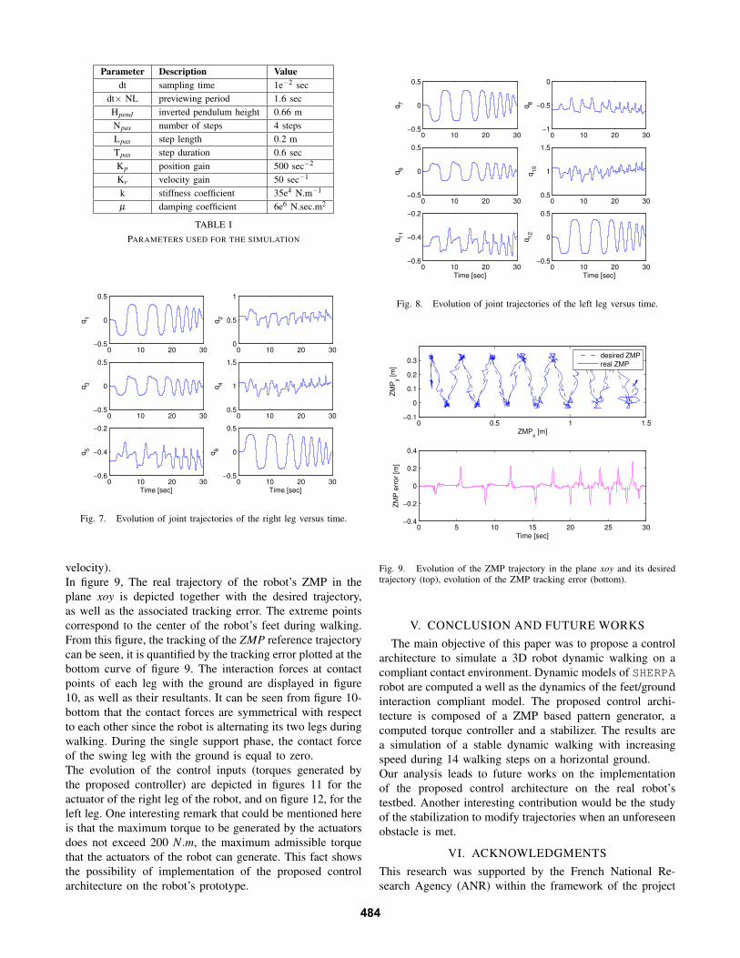
In figure 9, The real trajectory of the robot’s ZMP in the
plane xoy is depicted together with the desired trajectory,
as well as the associated tracking error. The extreme points
correspond to the center of the robot’s feet during walking.
From this figure, the tracking of the ZMP reference trajectory
can be seen, it is quantified by the tracking error plotted at the
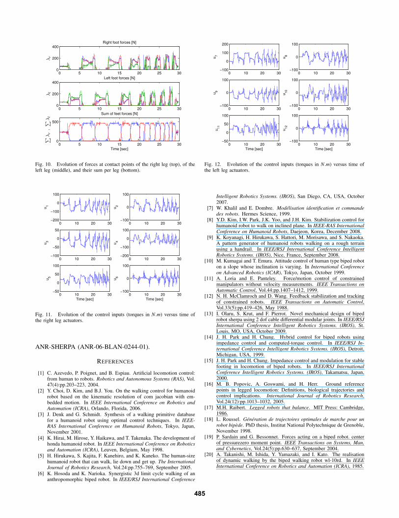
bottom curve of figure 9. The interaction forces at contact
points of each leg with the ground are displayed in figure
10, as well as their resultants. It can be seen from figure 10-
bottom that the contact forces are symmetrical with respect
to each other since the robot is alternating its two legs during
walking. During the single support phase, the contact force
of the swing leg with the ground is equal to zero.
The evolution of the control inputs (torques generated by
the proposed controller) are depicted in figures 11 for the
actuator of the right leg of the robot, and on figure 12, for the
left leg. One interesting remark that could be mentioned here
is that the maximum torque to be generated by the actuators
does not exceed 200 N.m, the maximum admissible torque
that the actuators of the robot can generate. This fact shows
the possibility of implementation of the proposed control
architecture on the robot’s prototype.
0 10 20 30−0.5
0
0.5
q7
0 10 20 30−1
−0.5
0
q8
0 10 20 30−0.5
0
0.5
q9
0 10 20 300.5
1
1.5
q1
0
0 10 20 30−0.6
−0.4
−0.2
Time [sec]
q1
1
0 10 20 30−0.5
0
0.5
Time [sec]
q1
2
Fig. 8. Evolution of joint trajectories of the left leg versus time.
0 0.5 1 1.5−0.1
0
0.1
0.2
0.3
ZMPx [m]
ZM
Py [
m]
desired ZMP
real ZMP
0 5 10 15 20 25 30−0.4
−0.2
0
0.2
0.4
Time [sec]
ZM
P e
rro
r [m
]
Fig. 9. Evolution of the ZMP trajectory in the plane xoy and its desiredtrajectory (top), evolution of the ZMP tracking error (bottom).
V. CONCLUSION AND FUTURE WORKS
The main objective of this paper was to propose a control
architecture to simulate a 3D robot dynamic walking on a
compliant contact environment. Dynamic models of SHERPA
robot are computed a well as the dynamics of the feet/ground
interaction compliant model. The proposed control archi-
tecture is composed of a ZMP based pattern generator, a
computed torque controller and a stabilizer. The results are
a simulation of a stable dynamic walking with increasing
speed during 14 walking steps on a horizontal ground.
Our analysis leads to future works on the implementation
of the proposed control architecture on the real robot’s
testbed. Another interesting contribution would be the study
of the stabilization to modify trajectories when an unforeseen
obstacle is met.
VI. ACKNOWLEDGMENTS
This research was supported by the French National Re-
search Agency (ANR) within the framework of the project
484
0 5 10 15 20 25 300
200
400λ
r
Right foot forces [N]
0 5 10 15 20 25 300
200
400
λl
Left foot forces [N]
0 5 10 15 20 25 300
500
∑
λr
,∑
λl
Sum of feet forces [N]
Time [sec]
Fig. 10. Evolution of forces at contact points of the right leg (top), of theleft leg (middle), and their sum per leg (bottom).
0 10 20 30−200
−100
0
100
u1
0 10 20 30−100
0
100
u2
0 10 20 30−100
−50
0
50
u3
0 10 20 30−200
−100
0
100
u4
0 10 20 30−50
0
50
100
Time [sec]
u5
0 10 20 30−100
0
100
Time [sec]
u6
Fig. 11. Evolution of the control inputs (torques in N.m) versus time ofthe right leg actuators.
ANR-SHERPA (ANR-06-BLAN-0244-01).
REFERENCES
[1] C. Azevedo, P. Poignet, and B. Espiau. Artificial locomotion control:from human to robots. Robotics and Autonomous Systems (RAS), Vol.47(4):pp.203–223, 2004.
[2] Y. Choi, D. Kim, and B.J. You. On the walking control for humanoidrobot based on the kinematic resolution of com jacobian with em-bedded motion. In IEEE International Conference on Robotics and
Automation (ICRA), Orlando, Florida, 2006.
[3] J. Denk and G. Schmidt. Synthesis of a walking primitive databasefor a humanoid robot using optimal control techniques. In IEEE-
RAS International Conference on Humanoid Robots, Tokyo, Japan,November 2001.
[4] K. Hirai, M. Hirose, Y. Haikawa, and T. Takenaka. The development ofhonda humanoid robot. In IEEE International Conference on Robotics
and Automation (ICRA), Leuven, Belgium, May 1998.
[5] H. Hirukawa, S. Kajita, F. Kanehiro, and K. Kaneko. The human-sizehumanoid robot that can walk, lie down and get up. The International
Journal of Robotics Research, Vol.24:pp.755–769, September 2005.
[6] K. Hosoda and K. Narioka. Synergistic 3d limit cycle walking of ananthropomorphic biped robot. In IEEE/RSJ International Conference
0 10 20 30−100
0
100
200
u7
0 10 20 30−100
0
100
u8
0 10 20 30−100
0
100
u9
0 10 20 30−100
0
100
u1
0
0 10 20 30−50
0
50
100
Time [sec]
u1
1
0 10 20 30−100
0
100
Time [sec]
u1
2
Fig. 12. Evolution of the control inputs (torques in N.m) versus time ofthe left leg actuators.
Intelligent Robotics Systems. (IROS), San Diego, CA, USA, October2007.
[7] W. Khalil and E. Dombre. Modelisation identification et commande
des robots. Hermes Science, 1999.[8] Y.D. Kim, I.W. Park, J.K. Yoo, and J.H. Kim. Stabilization control for
humanoid robot to walk on inclined plane. In IEEE-RAS International
Conference on Humanoid Robots, Daejeon, Korea, December 2008.[9] K. Koyanagi, H. Hirukawa, S. Hattori, M. Morisawa, and S. Nakaoka.
A pattern generator of humanoid robots walking on a rough terrainusing a handrail. In IEEE/RSJ International Conference Intelligent
Robotics Systems. (IROS), Nice, France, September 2008.[10] M. Kumagai and T. Emura. Attitude control of human type biped robot
on a slope whose inclination is varying. In International Conference
on Advanced Robotics (ICAR), Tokyo, Japan, October 1999.[11] A. Loria and E. Panteley. Force/motion control of constrained
manipulators without velocity measurements. IEEE Transactions on
Automatic Control, Vol.44:pp.1407–1412, 1999.[12] N. H. McClamroch and D. Wang. Feedback stabilization and tracking
of constrained robots. IEEE Transactions on Automatic Control,Vol.33(5):pp.419–426, May 1988.
[13] I. Olaru, S. Krut, and F. Pierrot. Novel mechanical design of bipedrobot sherpa using 2 dof cable differential modular joints. In IEEE/RSJ
International Conference Intelligent Robotics Systems. (IROS), St.Louis, MO, USA, October 2009.
[14] J. H. Park and H. Chung. Hybrid control for biped robots usingimpedance control and computed-torque control. In IEEE/RSJ In-
ternational Conference Intelligent Robotics Systems. (IROS), Detroit,Michigan, USA, 1999.
[15] J. H. Park and H. Chung. Impedance control and modulation for stablefooting in locomotion of biped robots. In IEEE/RSJ International
Conference Intelligent Robotics Systems. (IROS), Takamatsu, Japan,2000.
[16] M. B. Popovic, A. Goswami, and H. Herr. Ground referencepoints in legged locomotion: Definitions, biological trajectories andcontrol implications. International Journal of Robotics Research,Vol.24(12):pp.1013–1032, 2005.
[17] M.H. Raibert. Legged robots that balance. MIT Press: Cambridge,1986.
[18] L. Roussel. Generation de trajectoires optimales de marche pour un
robot bipede. PhD thesis, Institut National Polytechnique de Grenoble,November 1998.
[19] P. Sardain and G. Bessonnet. Forces acting on a biped robot. centerof pressurezero moment point. IEEE Transactions on Systems, Man,
and Cybernetics, Vol.24(5):pp.630–637, September 2004.[20] A. Takanishi, M. Ishida, Y. Yamazaki, and I. Kato. The realisation
of dynamic walking by the biped walking robot wl-10rd. In IEEE
International Conference on Robotics and Automation (ICRA), 1985.
485