
User Guide for Alcatel Telephone User Guide for Alcatel Telephone Contents
Upload
khangminh22Category
view
0download
0
DIGITAL KEY TELEPHONE SYSTEM
INSTALLATION MANUAL
MODEL : GDK-FPII

GDK-FPIIDIGITAL KEY TELEPHONE SYSTEM
3
REVISION HISTORY
ISSUE Date REVISIONSISSUE 1.0ISSUE 1.1
ISSUE 1.2
ISSUE 1.3
1997.051997.091998.03
1998.05
1. Initial Release1. Add the description of ISDN 2BRI installation.1. Table 2.3.3 Electrical Specifications.2. Power Installation.1. Add the description of Ferrite core installation on audio cables.
ISSUE 2.0
ISSUE 2.1
1998.09
1998.09
1. The manufacturer is changed to LGIC.2. Separate from the software programming manual.1. The design of KSU and board is changed.
ISSUE 3.0 1998.12 1. The PSU is changed from Linear type to SMPS type.
ISSUE 4.0
ISSUE 4.1ISSUE 4.2
1999.10
2000.122001.02
1. Update ISDN boards and their installation2. Update the cabling method of the whole system3. Add SMEMU, 2B-modules, CTI module, GDK-TRC1 module, BWDIDB.4. Update the Customer Database Programming (99A version).5. Add Alpha-numeric INDEX.1. Added 99A Plus Version.1. Added APPENDIX D(GDK-PHU installation).

GDK-FPIIDIGITAL KEY TELEPHONE SYSTEM
4
Table of Contents
SECTION 1. INTRODUCTION..........................................................................................9
1.1 PURPOSE ..................................................................................................................................91.2 REGULATORY INFORMATION....................................................................................................9
1.2.1 Telephone Company Notification ...........................................................................................91.2.2 Incidence Of Harm ...............................................................................................................91.2.3 Changes In Service..............................................................................................................91.2.4 Maintenance Limitations .....................................................................................................101.2.5 Notice Of Radiated Emissions.............................................................................................101.2.6 Hearing Aid Compatibility....................................................................................................101.2.7 Notice Of Replacement with Lithium Battery.........................................................................10
SECTION 2. GENERAL DESCRIPTION ...................................................................11
2.1 INTRODUCTION ....................................................................................................................... 112.2 SYSTEM CAPACITY.................................................................................................................12
2.2.1 System Capacity................................................................................................................122.2.2 System Configuration Chart ................................................................................................13
2.2.2.1 Overview.....................................................................................................................132.2.2.2 Typical System Configuration Chart ...............................................................................142.2.2.3 System Configuration Chart with PRI Line......................................................................152.2.2.4 System Configuration Chart without PRI Line.................................................................16
2.3 SYSTEM SPECIFICATIONS ......................................................................................................172.4 SYSTEM COMPONENTS ..........................................................................................................20
2.4.1 KSU (Key Service Unit) ......................................................................................................202.4.2 PSU (Power Supply Unit)....................................................................................................202.4.3 MBU (Main Board Unit).......................................................................................................202.4.4 RGU (Ring Generator Unit).................................................................................................212.4.5 PFTU/PFTU-I (Power Failure Transfer Unit).........................................................................212.4.6 DVIB (Digitized Voice Interface Board).................................................................................222.4.7 Extension Boards ...............................................................................................................23
2.4.7.1 DTIB (Digital Terminal Interface Board)..........................................................................232.4.7.2 ETIB (Electronic Terminal Interface Board).....................................................................232.4.7.3 SLIB/4SLI (Single Line Interface Boards).......................................................................242.4.7.4 WTIB /WTIU (Wireless Terminal Interface Board / Unit)...................................................25
2.4.8 Analog CO line Boards .......................................................................................................252.4.8.1 LCOB/4LCO (Loop Start CO Line Interface Board).........................................................262.4.8.2 AC15 Board(AC15 private Line Interface Board) - UK .....................................................262.4.8.3 TLIB (Tie Line Board) -Korea ........................................................................................262.4.8.4 BWDIDB (Both-way Direct Inward Dialing Board) - New Zealand.....................................27
2.4.9 ISDN Boards......................................................................................................................272.4.9.1 ISDN PRI (Primary Rate Interface Board) ......................................................................272.4.9.2 ISDN 2BRI (Basic Rate Interface Board: T interface only)...............................................282.4.9.3 ISDN STIB (S/T Basic Rate Interface Board: switchable S/T interface) ............................28
2.4.10 Add-on boards ...................................................................................................................29

GDK-FPIIDIGITAL KEY TELEPHONE SYSTEM
5
2.4.10.1 MEMU (Memory Expansion Unit) ..................................................................................292.4.10.2 SMEMU (Security Memory Expansion Unit)...................................................................302.4.10.3 MODU (Modem Unit)....................................................................................................302.4.10.4 PLLU2 (Phase Locked Loop Unit2)................................................................................312.4.10.5 SIU (Serial Interface Unit) .............................................................................................312.4.10.6 DTRU (DTMF Receiver Unit).........................................................................................312.4.10.7 MSGU (Message Wait Unit)..........................................................................................312.4.10.8 CPTU (Call Progress Tone Detection Unit: CPTU/A, CPTU/B).........................................322.4.10.9 CMU (Call Metering Unit)..............................................................................................322.4.10.10 DMEU/DMEU4 (DRAM Memory Expansion Units)..........................................................322.4.10.11 ADPU (ADPCM unit) ....................................................................................................32
2.4.11 Keyset & Terminals ............................................................................................................332.4.11.1 Digital Keysets and Terminals .......................................................................................332.4.11.2 Electronic Keysets and Terminals..................................................................................342.4.11.3 2B-module ...................................................................................................................362.4.11.4 GDK-PC PHONE (CTI).................................................................................................37
2.4.12 Cables (5MC1, 5MC2)........................................................................................................382.4.13 BRI Line Termination Board (GDK-162/100 TERM: 2923NP1656A).......................................382.4.14 Trace Tool (GDK-TRC1) .....................................................................................................382.4.15 Test Accessories for the Purpose of Test. ............................................................................38
SECTION 3. INSTALLATION..........................................................................................45
3.1 INTRODUCTION .......................................................................................................................453.2 SITE PREPARATION.................................................................................................................45
3.2.1 General Site Consideration .................................................................................................453.2.2 Back-Board Installation.......................................................................................................463.2.3 Verify On-Site Equipment....................................................................................................46
3.3 KSU INSTALLATION.................................................................................................................473.3.1 Mounting KSU....................................................................................................................483.3.2 RGU Installation.................................................................................................................493.3.3 PFTU Installation................................................................................................................503.3.4 KSU Grounding..................................................................................................................513.3.5 PSU Installation .................................................................................................................52
3.4 PCB INSTALLATION.................................................................................................................543.4.1 PCB Handling & General Installation ...................................................................................543.4.2 MBU Installation.................................................................................................................56
3.4.2.1 MEMU Installation ........................................................................................................593.4.2.2 SMEMU Installation......................................................................................................593.4.2.3 PLLU2 Installation ........................................................................................................603.4.2.4 MODU Installation ........................................................................................................603.4.2.5 SIU Installation.............................................................................................................60
3.4.3 Extension Board Installation................................................................................................613.4.3.1 DTIB Installation...........................................................................................................613.4.3.2 ETIB Installation...........................................................................................................623.4.3.3 SLIB/4SLI Installation...................................................................................................633.4.3.4 DTRU Installation.........................................................................................................643.4.3.5 MSGU Installation ........................................................................................................64
3.4.4 Analog CO Line Board Installation.......................................................................................64

GDK-FPIIDIGITAL KEY TELEPHONE SYSTEM
6
3.4.4.1 LCOB/4LCO Installation................................................................................................653.4.4.2 AC15 Board Installation - UK ........................................................................................673.4.4.3 TLIB Installation - Korea ...............................................................................................673.4.4.4 BWDIDB Installation - New Zealand ..............................................................................68
3.4.5 ISDN Board Installation ......................................................................................................683.4.5.1 ISDN 2BRI ( Basic Rate T Interface) Installation.............................................................683.4.5.2 ISDN STIB ( Basic Rate S/T Interface) Installation..........................................................703.4.5.3 ISDN PRI ( Primary Rate Interface) Installation ..............................................................73
3.4.6 DVIB Installation ................................................................................................................743.5 SYSTEM WIRING......................................................................................................................76
3.5.1 Battery Back-Up Wiring ......................................................................................................763.5.2 RS-32C WIRING on SIU.....................................................................................................773.5.3 MBU wiring .......................................................................................................................78
3.5.3.1 External Music Source wiring ........................................................................................793.5.3.2 External Paging wiring..................................................................................................793.5.3.3 External Paging Port and General Purpose Relays wiring...............................................803.5.3.4 Relay Contacts for General Purpose..............................................................................803.5.3.5 Alarm Detection wiring..................................................................................................813.5.3.6 Contact Assignments of RJ21 Type Connector for Basic Connection ...............................81
3.5.4 Extension Board wiring .......................................................................................................833.5.4.1 Digital Keyset and Terminal wiring .................................................................................833.5.4.2 Electronic Keyset and Terminal wiring............................................................................853.5.4.3 Single line Telephone wiring..........................................................................................873.5.4.4 Intercom/Door Phone Box installation ............................................................................883.5.4.5 Contact Assignments of RJ21 Type Connectors for Expansion connection.......................90
3.5.5 PFTU Wiring ......................................................................................................................913.5.6 Analog CO line wiring .........................................................................................................93
3.5.6.1 LCOB/4LCO wiring.......................................................................................................933.5.6.2 AC15 Board wiring - UK................................................................................................943.5.6.3 BWDIDB wiring - New Zealand......................................................................................953.5.6.4 TLIB wiring - Korea.......................................................................................................963.5.6.5 Contact Assignments of RJ21 type connectors on Analog CO line board .........................97
3.5.7 ISDN wiring .......................................................................................................................983.5.7.1 ISDN 2BRI wiring....................................................................................................... 1013.5.7.2 ISDN STIB wiring....................................................................................................... 1023.5.7.3 ISDN PRI wiring ......................................................................................................... 1033.5.7.4 Terminating Resistors on Basic Rate interface(2BRI/STIB)............................................ 1043.5.7.5 Clock Control Connection- Multi ISDN board installation............................................... 1053.5.7.6 QSIG connection........................................................................................................ 109
3.5.8 Contact Assignments of various types of connectors .......................................................... 1103.5.8.1 RJ21 type connectors ................................................................................................. 1103.5.8.2 Miniature 6-position jack ............................................................................................. 1103.5.8.3 Miniature 8-position jack for ISDN connection ...............................................................111
SECTION 4. ISDN BOARDS.........................................................................................112
4.1 Basic Information ............................................................................................................. 1124.2 Station/CO Line Number Assignments............................................................................... 1134.3 Other Information............................................................................................................. 113

GDK-FPIIDIGITAL KEY TELEPHONE SYSTEM
7
SECTION 5. CUSTOMER DATABASE PROGRAMMING ..............................114
5.1 INTRODUCTION ..................................................................................................................... 1145.2 TO ENTER THE PROGRAMMING MODE ................................................................................ 1145.3 PERMANENT UPDATE PROCEDURE..................................................................................... 1155.4 NUMBERING PLAN ................................................................................................................ 1155.5 ADMIN PROGRAMMING INDEX .............................................................................................. 1195.6 DEFAULT VALUES ................................................................................................................. 121
TABLE 5.6.1 INITIALIZATION................................................................................................... 121TABLE 5.6.2 FLEXIBLE NUMBERING PLAN – GDK-162 ........................................................... 121TABLE 5.6.3 FLEXIBLE NUMBERING PLAN – GDK-100 ........................................................... 122TABLE 5.6.4 FLEXIBLE NUMBERING PLAN – GDK-FPII........................................................... 124TABLE 5.6.5 SLOT ASSIGNMENT............................................................................................ 125TABLE 5.6.6 MSN/SUB-ADDRESS ASSIGNMENT.................................................................... 126TABLE 5.6.7 FLEXIBLE DID TABLE PROGRAM........................................................................ 126TABLE 5.6.8 EMERGENCY SERVICE CALL............................................................................. 126TABLE 5.6.9 LCR TABLE ASSIGNMENT................................................................................... 126TABLE 5.6.10 SYSTEM ATTRIBUTE - IV .................................................................................... 127TABLE 5.6.11 ISDN COLP TABLE ASSIGNMENT....................................................................... 127TABLE 5.6.12 STATION BASE PROGRAM ................................................................................ 127TABLE 5.6.13 STATION LINK PROGRAM................................................................................... 129TABLE 5.6.14 FLEXIBLE BUTTONS PROGRAM......................................................................... 129TABLE 5.6.15 CO LINE BASE PROGRAM.................................................................................. 130TABLE 5.6.16 SYSTEM BASE PROGRAM.................................................................................. 131TABLE 5.6.17 TOLL TABLE........................................................................................................ 136TABLE 5.6.18 PRINT DATABASE............................................................................................... 137TABLE 5.6.19 NATION SPECIFIC SYSTEM PROGRAM.............................................................. 137TABLE 5.6.20 SYSTEM ATTRIBUTE .......................................................................................... 137
APPENDIX A. Maximum Number of Boards in a System........................................... 138APPENDIX B. Power Consumption ................................................................................. 139APPENDIX C. PSU Installation .......................................................................................... 140APPENDIX D. GDK-PHU Installation................................................................................ 142APPENDIX E. Declaration of Conformity........................................................................ 143
Alpha-Numeric INDEX............................................................................................................144

GDK-FPIIDIGITAL KEY TELEPHONE SYSTEM
8
SECTION 1. INTRODUCTION
1.1 PURPOSE
This manual provides the information necessary to install, operate, and maintain the LG Digital KeyTelephone System (GDK-FPII, GDK-34I and GDK-34e). For the system Administration Programming,see the PROGRAMMING MANUAL, which is separately supplied.
l Note: The model name of GDK-FPII may be called as GDK-34i, GDK-34e in some specialcountries, but the system is the same. In this manual, GDK-FPII will be mainlydescribed as a model name.
1.2 REGULATORY INFORMATION
1.2.1 Telephone Company Notification
Before connecting the GDK-FPII to the telephone network, you may be required to notify your localservicing telephone company of your intention to use "customer provided equipment". You may furtherbe required to provide any or all of the following information;
l Number of telephone lines to be connected to the systeml Model name of GDK-FPII (GDK-34i, GDK-34e)l Local regulatory agency registration numberl Ringer equivalencel Registered jackThe necessary information is available from your local representative of LGE.
1.2.2 Incidence Of Harm
If the telephone company determines that the customer provided equipment is faulty due to any possiblycausing harm or interruption in service to the telephone network, it should be disconnected until repaircan be effected. If this is not done, the telephone company may temporarily disconnect service.
1.2.3 Changes In Service
The local telephone company may make changes in its communication facilities or procedures. Ifthese changes could reasonably be expected to affect using the GDK-FPII system or compatibility withthe network, the telephone company is required to give advanced written notice to user, allowing theuser to take appropriate steps to maintain telephone service.

GDK-FPIIDIGITAL KEY TELEPHONE SYSTEM
9
1.2.4 Maintenance Limitations
Maintenance on the GDK-FPII Digital Key Telephone System should be only performed by LGE. or itsauthorized agent. The user may not make any changes and/or repairs except as specifically noted inthis manual. Unauthorized alternations or repairs may affect the regulatory status of the system andmay void any remaining warranty.
1.2.5 Notice Of Radiated Emissions
The GDK-FPII Digital Key Telephone System complies with rules regarding radiation and radiofrequency emission as defined by local regulatory agencies. In accordance with these agencies, youmay be required to provide information such as the following to the end user.
WARNING :
"This equipment generates and uses R.F.energy, and if not installed and used inaccordance with the Instruction Manual, it may cause interference to radiocommunications. It has been tested and found to comply with the appropriate limits for atelecommunication device. The limits are designed to provide reasonable protectionagainst such interference, when operated in a commercial environment.
Operation of this equipment in a residential area could cause interference, in which case theuser, at his own expense, will be required to take whatever measures may be required tocorrect the interference."
1.2.6 Hearing Aid Compatibility
The GDK-FPII Digital Key Telephone System has been designed to comply with theHearing Aid Compatibility requirements as defined in Section 68.316 of Part 68 FCC Rules.
1.2.7 Notice Of Replacement with Lithium Battery
This product is also designed for IT power system with Phase to Phase voltage 230V.
CAUTION
- Danger of explosion if the battery is incorrectly replaced.- Replace only with the same or equivalent type recommended by the manufacturer.- Dispose of used batteries according to the manufacturer’s instructions.

GDK-FPIIDIGITAL KEY TELEPHONE SYSTEM
10
SECTION 2. GENERAL DESCRIPTION
2.1 INTRODUCTION
The GDK-FPII Digital Key Telephone System is a fully digital hybrid Key Telephone System, designedto meet the telecommunication needs of small/medium sized business offices.
The GDK-FPII system incorporates state of the art digital technology for command processing andvoice switching, utilizing a Pulse Code Modulation/Time Division Multiplexing (PCM/TDM, "A" law)distributed switching matrix.
The GDK-FPII system achieves a high level of flexibility by 1) employing a Universal Card Slotarchitecture with a cabinet to house plug-in Printed Circuit Boards, and 2) providing support fordifferent types of instrumentation.
The KSU of the GDK-FPII is a wall-mounted cabinet that houses the MBU (Main Board Unit) andcontains card slots for the CO line/Key Station/SLT/ISDN/DECT interface boards, and other usefulPCBs. There are 7 slots in the system, four (slot #4~7) of them are universal slots and others(slot#1~3) are fixed slots for specific cards. The 1st fixed slot (slot #1) is used to install only one of theDVIB, STIB or WTIB, the 2nd fixed slot(slot #2) is used to install the 4SLI(SLT interface card) card onlyand the 3rd fixed slot(slot #3) is used to install one of the 4LCO, 2BRI or PRI card.
There are four universal slots (slot #4~7) in the system. Station, CO line, SLT, and another optionboard can be installed to the system universal card slots up to the system’s maximum configuration.Thus, the system capacity is established by the number of installed interface boards and is not limitedby an artificially fixed station to CO line ratio.
The system architecture has been designed to allow a high level of software control over the system'shardware. The software incorporates a vast array of features and capabilities including PC DatabaseAdministration, Auto Route Selection, ACD, etc.
The GDK-FPII system supports a combination of Digital Keysets (KD, KD/E, KD/S, KD/C, LKDseries), Electronic Keysets(GSX, GSX/E series), various kinds of ISDN terminals, and wirelessterminals as well as analogue single line devices. With the keysets, commonly used features areactivated by direct button selection. Additionally, many functions may be accessed by dialing specificcodes or optionally, by assigning these dial codes to flexible buttons on the keyset. In addition to keytelephones, an array of optional terminals is available including DSS/DLS Console, Intercom/Door Box.
With the flexibility of the GDK-FPII extensive feature content, and the capability to use an array of
instruments, the GDK-FPII can be tailored to meet the short and long term needs of the mostdemanding customer requirements.

GDK-FPIIDIGITAL KEY TELEPHONE SYSTEM
11
2.2 SYSTEM CAPACITY
The following Table and Chart provide system capacities and displays the configuration flexibility of thesystem.
2.2.1 System Capacity
Table 2.2.1 System Capacities
Description Basic & Expansion Total
Time Slots 96
CO Line Ports Max. 20 (with analog CO ) 1)Max. 24 (with ISDN BRI) 1)Max. 34 (with ISDN PRI) 1)
Station Ports(Digital/Electronic/SLT/DECT)
Max. 48 ( without GAP-DECT) 1)Max. 64 ( with GAP-DECT) 1)
DSS/DLS Consoles 3/Keyset
Attendant Positions 1 System, 5 Main, 5Group Attendants
Intercom Links Non-blocking
Paging All Call External Internal
1 zone1 zone
5 zones
Station Speed Dial 20/station, 24 digits each 200
System Speed Dial 24 digits each 200
Last Number Redial 48 digits
Save Number Redial 48 digits
Memo Dial 48 digits
SMDR 100 (without MEME/SMEMU)2,000 (with MEMU/SMEMU)
2,000
Music Source Inputs 1 internal / MBU1 external / MBU
2
External Control Contacts Flexibly assigned 2 / MBU
Alarm/Door Bell Input 1 / MBU
Power Fail Circuits 6 lines / PFTU2 lines / PFTU-I
20
RS 232C Ports 1 / SIU 2) 2
DTMF Receivers 2 / MBU 3)2 / DTRU
14
CO Line Groups 9
Intercom Groups 5
Hunt/UCD Groups 8
DISA Lines All CO ports
Conference 3-party4-party5-party
no limit135

GDK-FPIIDIGITAL KEY TELEPHONE SYSTEM
12
l Note:
1) Not all maximum capacities may be achieved simultaneously.
For the maximum number of boards in a system, see APPEDIX A.
The 2B-modules are limited by the power capacity.
The maximum extensions with PSU(Linear) are limited by 34 without WTIB and 48 with
WTIB, because of its power capacity.
The maximum extensions with PSU2(SMPS) are limited by 48 without WTIB and 64 with
WTIB.
2) The SIU has one channel of RS-232. Normally, one SIU can be installed in the position of SIU(1)on MBU. However, in case that MODU is not installed, one more SIU can be installed in theposition of SIU(2) on MBU. The purpose of each SIU can be programmable in AdminProgramming.
3) A DTRU contains two DTMF receiver circuits, and can be installed on 4LCO, LCOB, 4SLI andSLIB as a optional.
MBU contains two DTMF receiver circuits.
2.2.2 System Configuration Chart
2.2.2.1 Overview
This typical Configuration Chart is made up according to the physical capacity of system, without 2B-module and Wireless Terminal(GAP-DECT).
Maximum capacity can be limited by software version and the type of PSU.
a) With relation to the type of PSU, refer to note 1 on table 2.2.1.
Manufacturing GDK-FPII PSU(linear) has been officially stopped after launching
PSU2(SMPS) in 1st half of 1999.
b) At the main program version 1.2Xx or earlier,
The number of stations should not be over 34 even though 2B-modules are connected.
c) At the main program version 1.4Xx or later,
- If the WTIB is not installed, the number of stations should not be over 48.
- If the WTIB is installed, the number of stations except Wireless Terminal should not be
over 32 and the number of stations including Wireless Terminal should not be over 64.
The following configuration charts, figures 2.2.2 to 2.2.5 can be made up in the system installed thesoftware version 1.4Xx or later, and PSU2(SMPS).

GDK-FPIIDIGITAL KEY TELEPHONE SYSTEM
13
2.2.2.2 Typical System Configuration Chart
l Note1) This typical Configuration Chart is made up according to the physical capacity of system, without
2B-module and Wireless Terminal (GAP-DECT).
0 6 10 16 22 28 34 Stations
34
30
(PRI)
24
20
16
12
8
4
CO
Basic DKT(6 ports in MBU) SLT(with 4SLI)
with PRI
with BRI including STIB, and Analog COwith Analog CO
FIGURE 2.2.2.2 GDK-FPII System Configuration Chart

GDK-FPIIDIGITAL KEY TELEPHONE SYSTEM
14
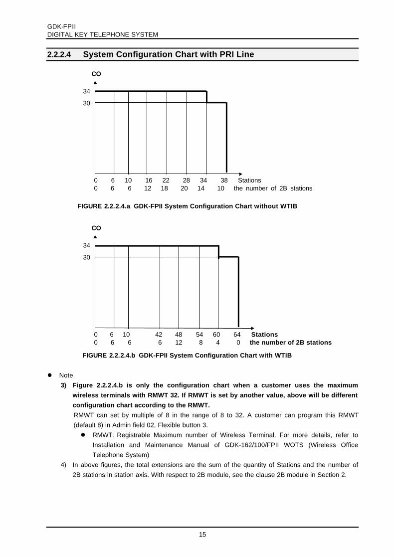
2.2.2.3 System Configuration Chart without PRI Line
l Note1) Figure 2.2.2.3.b is only the configuration chart when a customer uses the maximum
wireless terminals with RMWT 32. If RMWT is set by another value, above will be different
configuration chart according to the RMWT.
RMWT can set by multiple of 8 in the range of 8 to 32. A customer can program this RMWT(default 8) in Admin field 02, Flexible button 3.l RMWT: Registrable Maximum number of Wireless Terminal. For more details, refer to
Installation and Maintenance Manual of GDK-162/100/FPII WOTS (Wireless OfficeTelephone System)
2) In above figures, the total extensions are the sum of the quantity of Stations and the number of2B stations in station axis. With respect to 2B module, see the clause 2B module in Section 2.
0 6 10 42 48 54 60 Stations 0 6 6 6 12 10 4 the number of 2B stations
0 6 10 16 22 28 34 Stations 0 6 6 12 18 20 14 the number of 2B stations
24
20
16
12
8
4
CO
with BRI including STIB, and Analog COwith Analog CO
FIGURE 2.2.2.3.a GDK-FPII System Configuration Chart without WTIB
24
20
16
12
8
4
CO
with BRI including STIB, and Analog COwith Analog CO
FIGURE 2.2.2.3.b GDK-FPII System Configuration Chart with WTIB
GDK-FPIIDIGITAL KEY TELEPHONE SYSTEM
15
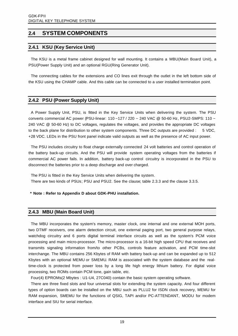
2.2.2.4 System Configuration Chart with PRI Line
l Note3) Figure 2.2.2.4.b is only the configuration chart when a customer uses the maximum
wireless terminals with RMWT 32. If RMWT is set by another value, above will be different
configuration chart according to the RMWT.
RMWT can set by multiple of 8 in the range of 8 to 32. A customer can program this RMWT(default 8) in Admin field 02, Flexible button 3.l RMWT: Registrable Maximum number of Wireless Terminal. For more details, refer to
Installation and Maintenance Manual of GDK-162/100/FPII WOTS (Wireless OfficeTelephone System)
4) In above figures, the total extensions are the sum of the quantity of Stations and the number of2B stations in station axis. With respect to 2B module, see the clause 2B module in Section 2.
FIGURE 2.2.2.4.a GDK-FPII System Configuration Chart without WTIB
0 6 10 16 22 28 34 38 Stations 0 6 6 12 18 20 14 10 the number of 2B stations
34
30
CO
0 6 10 42 48 54 60 64 Stations 0 6 6 6 12 8 4 0 the number of 2B stations
34
30
CO
FIGURE 2.2.2.4.b GDK-FPII System Configuration Chart with WTIB

GDK-FPIIDIGITAL KEY TELEPHONE SYSTEM
16
2.3 SYSTEM SPECIFICATIONS
The following Tables provide general system specifications.
Table 2.3.1 Dimensions & Weights
Items Height Width Depth Weight
Key Service Unit 463mm18.2in
403mm15.9in
160mm6.3in
15 Kg31.1 lbs
Digital Keyset 236mm9.3in
192mm7.6in
84mm3.3in
1.5 Kg3.3 lbs
Electronic Keyset 220mm8.6in
245mm9.6in
70mm2.8in
1.6 Kg3.5 lbs
Digital DSS/DLS Console 236mm9.3in
125mm4.9in
62mm2.4in
0.9 Kg2.0 1bs
Electronic DSS/DLS Console 236mm9.3in
125mm4.9in
62mm2.4in
0.9 Kg2.0 1bs
Digital ICM/Door Box 45mm1.8in
140mm5.5in
100mm3.9in
0.5 Kg1.1 1bs
Electronic ICM/Door Box 45mm1.8in
140mm5.5in
100mm3.9in
0.5 Kg1.1 1bs
Table 2.3.2 Environmental Specifications
degrees C degrees F
Operating Temperature 0-50 32-122
Optimum Operating Temperature 20-26 68-78
Storage Temperature 0-70 32-158
Relative Humidity 0-85% non-condensing

GDK-FPIIDIGITAL KEY TELEPHONE SYSTEM
17
Table 2.3.3 Electrical Specifications
Power Supply (PSU – linear): 1) AC Voltage Input AC Power AC Input Fuse
DC Output Voltages
AC 110-127V / AC 220-240V @ 47~63Hz100W
T 1.6A H250V (220-240V)T 3.15A L250V (110-127V)
+5, -5, +28Volts Power Supply (PSU2 – SMPS): AC Voltage Input AC Power AC Input Fuse DC Output Voltages
AC 88V~132V, AC 176V~264V @ 47~63Hz170W
T 3.15A H250V+5, -5, +28Volts
Back-up Battery : PSU Input Voltage PSU Battery Fuse Charging Current
24 Volt DC250 Volt/5AMax. 500mA
Ext. Relay Contacts 1 amp @ 24 Volt DC Music Source Input Max. 0 dBm @ 600 ohms External Page Port Max. 0 dBm @ 600 ohms
1 milli-watt max. input
l Note:
1. Manufacturing GDK-FPII PSU(linear) has been officially stopped after launching
PSU2(SMPS) in 1st half of 1999.
Table 2.3.4 Electrical Specifications
22 AWG Wire 24 AWG Wire
Digital Keyset 2-wire loop 500 m (1.6 Kft) 330 m (1 Kft)2B modules( with Power Adapter, 24Vdc/200 mA)
System – Primary KeysetPrimary Keyset – Secondary KeysetPrimary Keyset – Secondary SLT
300 m300 m1000 m
2B modules( without Power Adapter)System – Secondary KeysetSystem – Secondary SLT
10 m100 m
Electronic Keyset 4-wire loop
500 m (1.6 Kft)
330 m (1 Kft)
Single Line Telephone 2-wire loop
2,500 m (8.2 Kft) 1,600 m (5.2 Kft: 490 ohm)
l Note: The distance between KSU and SLT may differ from above in some countries,
because of the relevant special national specification.

GDK-FPIIDIGITAL KEY TELEPHONE SYSTEM
18
Table 2.3.5 CO Loop Specifications
Ring Detect Sensitivity 16-30 Hz, 40 Vrms
30-60 Hz, 30 Vrms
DTMF Dialing
Frequency Deviation
Signal Rise time
Tone Duration, on-time
Inter digit time
less than ±1%
3 msec, maximum
75 mesc, minimum
75 mesc, minimum
Pulse Dialing
Pulse Rate
Break/Make Ratio
10 pps or 20 pps
60/40% or 67/33%
l Note: Ring Detection sensitivity and Pulse Ratio may differ from above in some countries,
because of the relevant special national specification.
Table 2.3.6 Miscellaneous Specifications
Main System Memory Memory size
Read-Only-Memory, EPROM
Random Access Memory, RAM
basic = 2 Megabytes
basic = 256 Kbytes
expansion = 256 Kbytes (MEMU / SMEMU)
Account Codes Number
Number of codes
Digits per code
no limit
12
Authorization of codes Number
Number of codes
Digits per code
110
5
GDK-FPIIDIGITAL KEY TELEPHONE SYSTEM
19
2.4 SYSTEM COMPONENTS
2.4.1 KSU (Key Service Unit)
The KSU is a metal frame cabinet designed for wall mounting. It contains a MBU(Main Board Unit), aPSU(Power Supply Unit) and an optional RGU(Ring Generator Unit).
The connecting cables for the extensions and CO lines exit through the outlet in the left bottom side ofthe KSU using the CHAMP cable. And this cable can be connected to a user installed termination point.
2.4.2 PSU (Power Supply Unit)
A Power Supply Unit, PSU, is fitted in the Key Service Units when delivering the system. The PSUconverts commercial AC power (PSU-linear: 110 ~127 / 220 ~ 240 VAC @ 50-60 Hz, PSU2-SMPS: 110 ~240 VAC @ 50-60 Hz) to DC voltages, regulates the voltages, and provides the appropriate DC voltagesto the back plane for distribution to other system components. Three DC outputs are provided : ±5 VDC,+28 VDC. LEDs in the PSU front panel indicate valid outputs as well as the presence of AC input power.
The PSU includes circuitry to float charge externally connected 24 volt batteries and control operation ofthe battery back-up circuits. And the PSU will provide system operating voltages from the batteries ifcommercial AC power fails. In addition, battery back-up control circuitry is incorporated in the PSU todisconnect the batteries prior to a deep discharge and over charged.
The PSU is fitted in the Key Service Units when delivering the system.There are two kinds of PSUs; PSU and PSU2. See the clause; table 2.3.3 and the clause 3.3.5.
* Note : Refer to Appendix D about GDK-PHU installation.
2.4.3 MBU (Main Board Unit)
The MBU incorporates the system's memory, master clock, one internal and one external MOH ports,two DTMF receivers, one alarm detection circuit, one external paging port, two general purpose relays,watchdog circuitry and 6 ports digital terminal interface circuits as well as the system's PCM voiceprocessing and main micro-processor. The micro-processor is a 16-bit high speed CPU that receives andtransmits signaling information from/to other PCBs, controls feature activation, and PCM time-slotinterchange. The MBU contains 256 Kbytes of RAM with battery back-up and can be expanded up to 512Kbytes with an optional MEMU or SMEMU. RAM is associated with the system database and the real-time-clock is protected from power loss by a long life high energy lithium battery. For digital voiceprocessing, two ROMs contain PCM tone, gain table, etc.
Four(4) EPROMs(2 Mbytes : U1-U4, 27C040) contain the basic system operating software.There are three fixed slots and four universal slots for extending the system capacity. And four different
types of option boards can be installed on the MBU such as PLLU2 for ISDN clock recovery, MEMU forRAM expansion, SMEMU for the functions of QSIG, TAPI and/or PC-ATTENDANT, MODU for modeminterface and SIU for serial interface.
GDK-FPIIDIGITAL KEY TELEPHONE SYSTEM
20
There are 3 CHAMP connectors on the MBU’s left most side. The upper one is used to connect 6digital terminal interface circuits of the MBU, 4 single line interface circuits with 4SLI board that installedon the slot #2, and two dry contacts of general purpose relays. The middle one is used to connect COlines with CO interface board(s) that installed on slot #3~7. The last one is used to connect extensionlines (digital terminals or SLTs) with DTIB or SLIB that installed on universal slots (slot #4~7).
It should be noted that the analog keysets can be connected to the ETIB directly through modular typeconnectors –RJ11 on the ETIB.
The PSU is fitted in the KSU when delivering the system.MBU contains 1 internal and 1 external MOH sources, one external paging port, one alarm detection
circuit, 2 general purpose relays, 2 DTMF receivers, and 6 digital terminal interface ports on itself.Add-on boards: MEMU, SMEMU, PLLU2, MODU, SIU
2.4.4 RGU (Ring Generator Unit)
The Ring Generator Unit provides the 25Hz sinusoidal ring voltage to the 4SLI/SLIB circuits for ringing theSLT. The output of the RGU is 90Vac, 25Hz with RGU-EX and can support simultaneous ringing forfive(5) SLTs at a time, so up to 25 SLTs can be ringing by using time sharing technique.
The RGU is installed on the right bottom side of the KSU. And the RGU is electrically connected to theMBU.
2.4.5 PFTU/PFTU-I (Power Failure Transfer Unit)
PFTUThe PFTU provides the relay contacts for transfer of 6 CO Lines to 6 SLTs in the event of a power or
processor failure. The PFTU is installed outside of the KSU and up to 3 PFTU modules can be connectedto the KSU with the cascade connection of control wire. The PFTU is equipped with a manual switch thatactivates the Power Failure Transfer mode for testing purpose.
A 2-pin connector with screws is fitted for the control signal. And a RJ21 type male connector is fitted forthe connection between CO line, CO interface circuit, SLT interface circuit and SLT.
PFTU-IThe PFTU-I provides relay contacts for transferring the first 2 CO lines of the 4LCO boards to SLT in the
event of a power or processor failure. The PFTU-I can be installed on the 4LCO board only.

GDK-FPIIDIGITAL KEY TELEPHONE SYSTEM
21
2.4.6 DVIB (Digitized Voice Interface Board)
The Digitized Voice Interface Board (DVIB) provides announcements for the system's ACD/UCDfeatures as well as the System Voice Prompts and Recorded User Greetings. Following table shows thecapacity of memory, ADPCM channel of DVIB, and its optional board.
Table 2.4.6 The capacity of DVIB
Maximum CapacityItem Basic Option(for expansion)
a board a system
ADPCM channel 4 channels ADPU; 4channels 8 channels 16 channels
System Voice Prompt 2 EPROMs1 Mbytes240 seconds
none 1 Mbyte4 min.
1 Mbyte4 min.
ACD/UCDAnnouncement
6 SRAMs768 Kbytes180 seconds
none 768 Kbytes180 sec.(3 min)
768 Kbytes180 sec.(3 min)
User Greeting 8 DRAMs4 MBytes1024seconds
DMEU:2 Mbytes(512 seconds)orDMEU4:4 Mbytes(1024 seconds)
8Mbytes2048 sec.(34 min.)
16 Mbytes4096 sec.(68 min.)
l DVIB allows a DMEU or a DMEU4 to be expanded.l GDK-FPII allows up to 2 DVIB board to be installed.l ACD/UCD Announcements are protected from power loss by a long life lithium battery, but User
Greetings are not.l The capacity of ACD/UCD announcements will not be expanded even though 2 boards are
installed in a system.
DVIB employs ADPCM channel to store and play System Voice Prompts, ACD/UCD announcements,and Recorded User Greetings. All voice data will be stored and reproduced by using ADPCM techniquethat compresses the 64Kbps to the 32Kbps in record mode and expands the 32Kbps to the 64Kbps inplay mode.
Note that each channel can operate as either record or play mode at a time.The System Voice Prompts for the standard version of the DVIB are recorded in English. However,
customized recordings can be made available for local market requirements.
There are three option board, one is ADPU for ADPCM channel expansion and the others are DMEUand DMEU4 for DRAM expansion.
DVIB can be installed in any of slot No. 1 or slot No. 4~7.
And maximum two boards can be installed in a system.
Add-on boards: ADPU, DMEU, DMEU4

GDK-FPIIDIGITAL KEY TELEPHONE SYSTEM
22
2.4.7 Extension Boards
The various types of GDK-FPII Extension Boards have capable of supporting various types of terminalsas followings,
Board Name Function Remark
DTIB Provides 6 Digital Terminal interfaces 2 wire
ETIB Provides 6 Electronic Terminal interfaces 4 wire4SLI Provides 4 SLT interfaces with a line voltage of 24V. 2 wire
SLIB Provides 6 SLT interfaces with a line voltage of 24V. 2 wire
WTIB/WTIU Be capable of accommodating up to 8 Base Stations.(up to 64 wireless terminals)
4 wire
STIB Be capable of accommodating up to 2 ISDB BRI S interfaces, 4 Bchannels. (Each interface is T/S switchable)
4 wire
l Note:1. 4SLI can be only installed in slot No. 2. SLIB can be installed in the universal slots (slot No. 4~7).
2.4.7.1 DTIB (Digital Terminal Interface Board)
The DTIB provides 6 circuits of the LGE proprietary digital interface for the system. It provides 2-wireinterface to digital terminals. The DTIB functions as a MUX/DEMUX for the digitized voice and datasignals to and from the digital keysets by using the CHAMP connector (CN16) on the MBU. In addition,one LED is mounted on the PCB to indicate the state of connected keysets. LED will turn on when one ormore ports are busy. The DTIB allows for either 1 or 2 bearer voice channels from a single hardware portunder the control of system software. Note that each keyset requires only a single channel however, 2-channel operation can be provided for simultaneous voice and data applications or future feature as 2Bphone.
DTIB can be installed in any of four universal slots. (slot #4~7)
The maximum 4 boards can be installed in a system. See the clause 2.2 SYSTEM CAPACITY.
2.4.7.2 ETIB (Electronic Terminal Interface Board)
The ETIB allows GSX series of Electronic Keysets to be connected to the system. The PCB provides for6 interface circuits and incorporates circuitry for A/D and D/A conversion of voice signals, and interpretsand sends signaling data to and from the keysets. The ETIB has an industry standard modular jackconnector per interface and mounted on the front edge for connecting to the station termination port. Inaddition, a LED is mounted on the PCB to indicate the status of ports connected to the ETIB, LED willturn on when one or more ports are busy.
This board can be installed in any one of four universal slots. (slot #4~7)
The maximum 4 boards can be installed in a system. See the clause 2.2 SYSTEM CAPACITY

GDK-FPIIDIGITAL KEY TELEPHONE SYSTEM
23
2.4.7.3 SLIB/4SLI (Single Line Interface Board)
SLIB allows single line analog devices to be connected.Two kinds of SLIB boards are available in GDK-FPII system;
Board Name Interface circuit Feed voltage Remark
4 SLI 4 cct 24VDC battery feed In slot No. 2SLIB 6 cct 24VDC battery feed In universal slots
There are two kinds of Single Line Interface boards, one is 4SLI and the other is SLIB. The majordifference is the 4SLI board should be installed on slot #2 only and the SLIB can be installed on any oneof four universal slots (slot #4~7). The 4SLI provides the capability to connect 4 SLTs to the system, butthe SLIB provides the capability to connect 6 SLTs to the system with appropriate A/D and D/Aconversion. The 4SLI/SLIB allow SLT access to CO lines connected to the system, other stations, andmost features of the system through the use of dial codes. Connections to the single line telephones aremade via a 25-pair CHAMP connectors on the MBU. To connect SLTs to the GDK-FPII system, the 4SLIboard on slot #2 uses upper most CHAMP connector(CN14) and the SLIB(s) on the universal slot(s) useslower most CHAMP connector(CN16) of the MBU. The 4SLI/SLIB can be equipped with a Message Waitsource(optional MSGU), which activates a lamp in the SLT, if so equipped. The Message Wait sourcesends a 90Vdc signal to the SLT illuminating the message waiting lamp. And an optional DTMF receiverunit(DTRU) can be installed on the 4SLI/SLIB. A Ring Generator Unit is required in cabinet if a 4SLI/SLIBis installed. The 4SLI/SLIB allows a single line telephone to be connected up to 2.5 Kilometers (8,200feet, loop resistance: 490 ohm) from the system by using 22 AWG wire. In addition, a LED is mounted onthe PCB to indicate the status of interface circuits connected to 4LSI/SLIB, LED will turn on when one ormore ports are busy.
4SLI can be only installed in slot No. 2.SLIB can be installed in the universal slots (slot No. 4~7)The maximum 4 SLIBs can be installed in a system. See the clause 2.2 SYSTEM CAPACITY
Add-on boards: DTRU, MSGU

GDK-FPIIDIGITAL KEY TELEPHONE SYSTEM
24
2.4.7.4 WTIB /WTIU (Wireless Terminal Interface Board / Unit)
The WTIB provides standard interface between the GDK-FPII digital Key Telephone system and DECT(Digital Enhanced Cordless Telecommunications) Network. The system can accommodate one WTIB,which is capable of supporting up to 4 Base Stations. The WTIB can be optionally equipped with WTIU toexpand Base Stations, which can support up to additional 4 base stations. So the system allowsmaximum 8 Base Stations to be connected. Following table shows the capacity of WTIB and itsexpansion board.
Items WTIB Max. Capacity
with WTIU(expansion)
Maximum Cell Number(Base Station Number)
4 8
Voice channels / Cell 5 5
Registrable MaximumTerminal Number
8 – 32by step 8
8 – 32by step 8
Max. SimultaneousWireless calls
16 16
l Note1. Registrable Maximum Wireless Terminal numbers are programmable in Admin field 02.2. WTIB/WTIU contains RJ11 type connectors for the connection to Base Stations.
A WTIB should be installed in any of slot No. 1 or the universal slots (slot No. 4~7).
MEMU( or SMEMU ) should be installed on the MBU for proper operation.
For more details, see INSTALLATION and MAINTENANCE MANUAL (GAP) of GDK-162/100/FII
WOTS(Wireless Office Telephone System).
2.4.8 Analog CO Line Boards
GDK-FPII Analog CO line Boards have capable of supporting various types of analog CO line asfollowings,
Board Function connection
LCOB Provides Loop Start CO interfaces, 4 interfaces 2 wireAC15 Provides AC15a signaling interfaces, 2 interfaces; UK 4 wire
TLIB Provides 2-wire E&M interfaces, 2 interfaces; Korea 4 wire
BWDIDB Provides Both-way DID interfaces, 4 interfaces; New Zealand 2 wirel Note
Analog CO line Boards except LCOB are designed to comply with special national specification andapplication, so it may not suitable for the other national specification and/or application.

GDK-FPIIDIGITAL KEY TELEPHONE SYSTEM
25
2.4.8.1 LCOB/4LCO (Loop Start CO Line Interface Board)
There are two kinds of Loop-start CO line boards. One is 4LCO and the other is LCOB. The majordifference is the 4LCO board should be installed on slot #3 only, but the LCOB can be installed on anyone of four universal slots.(slot #4~7)
All these two boards have 4 Loop Start CO lines with ring and loop current detection, A/D and D/Aconversions, and pulse signaling. An optional Call Metering Unit(CMU) and a Call Progress Tonedetection Unit(CPTU) and a DTMF Receiver Unit(DTRU) can be installed on the 4LCO/LCOB.
An optional Power Failure Transfer Unit-I (PFTU-I) board can be installed on the 4LCO only. This PFTU-I supports power failure transfer function for the first two ports (CO1 & CO2) of the 4LCO boards.
For power failure transfer from LCOB, you have to use external PFTU module.
4LCO and LCOB contain four LEDs, one for each port, to indicate the status of each CO line.
4LCO can be only installed in slot No. 4.
LCOB can be installed in any of universal slots (slot No.4~7).
The maximum four LCOB can be installed in a system. See the clause 2.2 SYSTEM CAPACITY.
Add-on boards: DTRU, CPTU/A, CPTU/B, CMUPR/CMU50/CMU12/CMU16/CMU12PR/CMU50PR
2.4.8.2 AC15 Board (AC15 Private Line Interface Board) - UK
The AC15 board provides an analog interface between outside tone controlled private lines and thesystem. An AC15 board has 2 interface circuits and each AC15 private line interface circuit provides two-pair(transmitting and receiving) audio interface circuit and is designed to comply with the tone signalingrequirements of UK. There are two private line interface circuits per one board and each AC15 private lineinterface circuit provides the A/D and D/A conversions for audio and signaling to and from the system andAC15 private line. The AC15 board contains two LEDs to indicate the status of each line.
It is designed to comply with the UK specification and application, so it may not suitable for the othernational specification and/or application.
This board can be installed in any one of four universal slots.(slot #4~7).
The maximum four AC15 boards can be installed in a system. See the clause 2.2 SYSTEM
CAPACITY in section 2.
2.4.8.3 TLIB (Tie Line Board) -Korea
TLIB provides 2 interface circuits that can support 2-wire E&M or Ring Down according to theadministration. Each line supports E&M type V of E&M line.
The TLIB board contains two LEDs to indicate the status of each line.
It is designed to comply with the Korean specification and application, so it may not suitable for the othernational specification and/or application.
This board can be installed in any one of four universal slots.(slot #4~7).
The maximum four TLIBs can be installed in a system. See the clause 2.2 SYSTEM CAPACITY.
Add-on board: DTRU

GDK-FPIIDIGITAL KEY TELEPHONE SYSTEM
26
2.4.8.4 BWDIDB (Both-way Direct Inward Dialing Board) - New Zealand
BWDIDB provides 4 both-way DID interfaces, which support DTMF or Pulse dialing. It supports bothIncoming and Outgoing calls with pulse or DTMF.
Each interface consists of polarity reversal, pulse dialing, call direction control, open loop control, loopdetection and polarity detection circuit.
The BWDIDB contains four LEDs to indicate the status of each line. DTMF Receiver Unit (DTRU), CallProgress Tone detection units (CPTU/A) can be installed optionally on the BWDIDB.
It is designed to comply with the New Zealand specification and application, so it may not suitable for theother national specification and/or application.
This board can be installed in any one of four universal slots.(slot #4~7).
The maximum four BWDIDBs can be installed in a system. See the clause 2.2 SYSTEM
CAPACITY.
Add-on boards: DTRU, CPTU/A
2.4.9 ISDN Boards
GDK-FPII ISDN Boards are capable of supporting various types of ISDN as followings,
Board Function connection
PRI Provides ISDN Primary Rate interfaces,1 interface /30 B channels
4 wire
2BRI Provides ISDN Basic Rate interfaces(T),2 interfaces /4 B channels
4 wire
STIB Provides ISDN Basic Rate interfaces(T/S switchable),2 interfaces /4 B channels
4 wire
2.4.9.1 ISDN PRI (Primary Rate Interface Board)
PRI (Primary Rate Interface) board has capability of one(1) PRI line, which has a interface circuit for 30channel time slots with 2.048Mbps data rate speed. PRI will be positioned at reference point Ia(T) on ETS300. 001, that is TE slave without power feeding. And, Data & bit clock are transmitted by the NT masterand extracted by the TE slave.
PRI contains reset circuit, address decoder and DBID, and the board line’s specific circuitry withPEB2254. The PRI has no local micro-processor and the micro-processor on the MBU controls PRI carddirectly.
The PRI board can be installed only in the slot No. 3.
The PLLU2 MUST be installed for proper operation.
The MEMU( or SMEMU ) should be installed on the MBU for proper operation.
Only 1 PRI board can be installed in a system, and total CO lines should not be more than 34
lines(channels) including PRI and Analog lines..
QSIG function can be supported through PRI (software version 99A), and SMEMU MUST be used
for this function.

GDK-FPIIDIGITAL KEY TELEPHONE SYSTEM
27
2.4.9.2 ISDN 2BRI (Basic Rate Interface Board: T interface only)
2BRI has specified to support two interface circuits that allow interfacing the ISDN BRI. Data and bit clockare transmitted by the NT master and extracted by this board. The GDK-FPII system will be positioned atreference point Ia on ETS 300. 012, that is TE slave without power feeding.2BRI contains reset circuit, address decoder, the circuitry to control the highway interface (DBID), and theboard line’s specific circuitry with PEB2086 for physical layer and data link layer. The 2BRI has no localmicro-processor and the micro-processor on the MBU controls 2BRI card directly.
The 2BRI board can be installed only in the slot No. 3.
The PLLU2 MUST be installed for proper operation.
QSIG function can be supported through 2BRI (software version 99A), and SMEMU MUST be
used for this function.
2.4.9.3 ISDN STIB (Basic Rate Interface Board: switchable S/T interface)
The S,T interface is based on the existing interface described in ETSI 300. 012 which is based uponITU_T Recommendations I.430 and provides modifications and further requirements.
This is applied at the S or T reference points for the basic interface structure defined in ITU_T I.412.Layer 1 interfacing requires a balanced metallic transmission medium, for each direction of transmittingcapability to support 192Kbps(2B+D). Data & bit clock are transmitted by the NT master and extracted byTE slave. The GDK-FPII system can be positioned at reference point Ia(T) or Ib(S) on ETS 300. 012, thatis TE-slave without power feeding or NT-master with power feeding. By selecting the jumper position andDIP switch on each line interface, the STIB can support either S-interface (Line card function) or T-interface (Trunk function).
SCC1 of CPU(MC68LC302) is assigned as 512Kbps HDLC communication to main processor on MBU.SCC2 of CPU is assigned as 38400bps RS-232C channel. This RS-232C channel will be used only indevelopment stage for software and hardware debugging.
The board line’s specific circuitry contains PEB2086 for physical layer and data link layer.
STIB should be installed in the slot #1 and/or in any one of universal slots (slot #4~7).
The PLLU2 MUST be installed for proper operation.
The maximum 5 STIB boards can be installed in a system. But with respect to total CO lines and
extensions, See the clause 2.2 SYSTEM CAPACITY.
QSIG function can be supported through STIB T-interface only (software version 99A), and
SMEMU MUST be used for this function.

GDK-FPIIDIGITAL KEY TELEPHONE SYSTEM
28
2.4.10 Add-on boards
This chapter describes add-on boards, which can be installed on various types of boards to support theproper function
Board Name Function positionMEMU Expands SRAM size. MBUSMEMU Expands SRAM size and provides QSIG,CTI, and PCATTN. MBUMODU Provides a 1200/2400 baud modem for local access MBUPLLU2 Provides the synchronized system clock when ISDN installed. MBUSIU Provides additional an RS232 serial interface. MBUDTRU Provides further 2 DTMF receivers 1)MSGU Provides Message Waiting signals to 6 SLT ports 2)CPTU/A,CPTU/B Provides Call progress detection function 3)CMU Provides Call Metering signal detection 4)DMEU/DMEU4 Expands DRAM size for User Greetings(2M/4M) DVIBADPU Expands 4 ADPCM channels DVIB
l Note:1. DTRU can be installed on 4SLI, SLIB, LCOB, BWDIDB, and TLIB.2. MSGU can be installed on 4SLI and SLIB.3. CPTU/A, CPTU/B can be installed on LCOB, BWDIDB.4. Each type of CMU can be installed on the LCOB according to the local market condition and
regulatory requirements.5. MODU, PLLU2 (issue3 or later), DTRU, MSGU, CPTU/A, CPTU/B and ADPU can be commonly
used in both GDK-100 and GDK-FPII systems. But PLLU2 issue 2 or earlier can be only usedin GDK-FPII system.
6. CMU and DMEU/DMEU4 can be commonly used in GDK-162, GDK-100, and GDK-FPIIsystems.
2.4.10.1 MEMU (Memory Expansion Module)
The MBU contains the basic system RAM memory. The RAM provides the memory for the systemdatabase, speed dial numbers, SMDR buffer, etc. The basic RAM is 256 Kbytes and can be expanded upto 512 Kbytes with the MEMU.
MEMU is required for following function.- Increase the SMDR record buffer from 100 to 2,000- On-demand Ring- ISDN CLIP and CO Message Wait: up to 1000- ISDN Flexible DID table: 000~999 (* User programmable bins: 000~299)- MSN- ACD Statistics- Expanded LCR Table- WTIB (DECT GAP)- Enhanced CCR 1)
l Note:1) Above features are supported by the software 98FEB or later version. But the Enhanced
CCR is only supported by the software 99A or later version.
MEMU is optionally installed on the MBU.MEMU or SMEMU MUST be installed for the operation of PRI and/or WTIB.

GDK-FPIIDIGITAL KEY TELEPHONE SYSTEM
29
2.4.10.2 SMEMU (Security Memory Expansion Unit)
The SMEMU is an enhanced version of existing MEMU. So it provides all the function of MEMU. Inaddition, the SMEMU allows QSIG, TAPI and/or PC-ATTENDANT to be operated in GDK-FPII system.The memory size is 256 Kbytes.
SMEMU is required for following features.- Increase the SMDR record buffer from 100 to 2,000- On-demand Ring- ISDN CLIP and CO Message Wait: up to 1000- ISDN Flexible DID table: 000~999 (* User programmable bins: 000~299)- MSN- ACD Statistics- Expanded LCR Table- WTIB (DECT GAP)- Enhanced CCR 1)- QSIG 1), 2)- PC-Attendant 1), 2)- GDKSP based on TAPI 2.1 1), 2)l Note:
1) Above features are supported by the software 98FEB or later version. But the featuresmarked 1) are only supported by the software 99A or later version.
2) SMEMU should be required for the features marked 2).
The SMEMU can be optionally installed on the position of MEMU of MBU.SMEMU MUST be installed on the MBU for the proper operation of QSIG, TAPI and/or PC-
ATTENDANT in the system.
SMEMU or MEMU MUST be installed for the operation of PRI and/or WTIB.
2.4.10.3 MODU (Modem Unit)
The Modem Unit provides an asynchronous modem for access to the system database and faultreporting features from a remote site. The module is optionally installed on the MBU and incorporates a1200/2400 baud modem. The modem may be connected to a pre-selected CO line through the systemswitching matrix. The remote side which contains an external modem port, may be connected to thesystem through this MODU with pre-selected CO line. The MODU port is independent with the SIUstandard RS-232C port, allowing system database access, etc. without the need to interrupt the SMDRoutput.
Basically, the system can support two(2) serial channels at a time. One is SIU(1) for serial RS-
232C interface and the other is one of SIUs(2) for serial RS-232C interface or MODU for modem
function.
So, it should be noted that if the MODU is installed, the system supports one SIU(1) module.

GDK-FPIIDIGITAL KEY TELEPHONE SYSTEM
30
2.4.10.4 PLLU2 (Phase Locked Loop Unit)
PLLU2(PLL Unit 2) is an option board of MBU and generates 32.768MHz clock which is synchronized toISDN line. The 32.768MHz clock is provided to GSXD on the MBU. It consists PLL circuit and clock (fromDigital Trunk interface board) monitoring circuit.
For the system synchronization, the clock should be extracted from 2BRI, PRI or STIB. But, if clock isnot generated from 2BRI, PRI or STIB(clock from ISDN card is not present), this unit generates masterclock(32.768MHz) when ISDN card is absent, this unit generates master clock(32.768MHz) using internalclock.
The PLLU should be installed on MBU when any ISDN card is installed in the system.
2.4.10.5 SIU (Serial Interface Unit)
The Serial Interface Unit provides a RS-232C interface port with 9-pin connector. The maximum baudrate is 9600bps(default). The SIU is useful for system maintenance, PC based admin., SMDR print outand SMDI for PC based voice mail system. And two SIU boards can be installed on the position of SIU(1)and SIU(2) of the MBU when the MODU is not installed. Followings are the list of the system’s output;
- Administration database- Off-line SMDR (on-demand)- On-line SMDR- Statistical Information- SMDI (voice mail)- System trace data
The purpose of each SIU(1 & 2) can be defined by admin. programming.
2.4.10.6 DTRU (DTMF Receiver Unit)
One DTMF Receiver Unit contains 2 DTMF receiver circuits. The DTRU can be optionally installed onthe 4LCO/LCOB and 4SLI/SLIB and each receiver is time-shared under the control of the systemsoftware.
The DTRU can be optionally installed on 4SLI, SLIB, LCOB, BWDIDB, and TLIB.
The maximum DTMF receivers including DTMF receivers on MBU are 14 in a system.
2.4.10.7 MSGU (Message Wait Unit)
The Message Wait Unit sends a 90Vdc signal to the SLT for illuminating the Message Wait lamp. TheMessage Wait Unit contains 6 circuits to support 6 SLTs.
The MSGU can be installed on 4SLI/SLIB.
GDK-FPIIDIGITAL KEY TELEPHONE SYSTEM
31
2.4.10.8 CPTU (Call Progress Tone Detection Unit; CPTU/A, CPTU/B)
The Call Progress Tone Detection Unit is used to detect specific call progress tones which are suppliedfrom the CO or PABX. Tone detection is employed to support features such as ACNR(Automatic CalledNumber Redial).
CPTU provides 2 tone detection circuits that are time-shared under the control of the system software,as a system resource regardless its position.
CPTU have two versions; CPTU/A and CPTU/B. CPTU/A has wide tone detection range (305Hz -640Hz), and CPTU/B has narrow tone detection range (350Hz, 620Hz, 440Hz, 480Hz ± 1% ).
Any Kind of CPTU can be optionally installed on the LCOB and BWDIDB.
It is important to check the local specification regarding call progress tone to use CPTU/B.
2.4.10.9 CMU (Call Metering Unit)
The Call Metering Unit detects call metering signals from the CO or PABX to monitor callduration/charges. There are six kinds of CMUs as followings,
- 12KHz- 12KHz and Polarity Reversal- 16KHz- 50Hz Longitudinal- 50Hz Longitudinal and Polarity Reversal- Polarity Reversal
The CMU can be optionally installed on the 4LCO/LCOB and each CMU supports one CO line.
Each type of CMU can be installed on the LCOB according to the local market condition and
national regulatory requirements.
2.4.10.10 DMEU/DMEU4 (DRAM Memory Expansion Unit)
The DMEU or DMEU4 allows for expansion of the DRAM memory on the DVIB. The DMEU expands to512 seconds for Recorded User Greetings time. And the DMEU4 expands to 1024 seconds for RecordedUser Greetings time.
DMEU or DMEU4 can be optionally installed on the DVIB. See clause 2.4.8 DVIB.
2.4.10.11 ADPU (ADPCM Unit)
The ADPU allows for expansion of ADPCM channels on DVIB. The ADPU expands to 4 channels forADPCM.
ADPU can be optionally installed on DVIB,

GDK-FPIIDIGITAL KEY TELEPHONE SYSTEM
32
2.4.11 Keyset& Terminals
In addition to supporting analogue Single Line devices, by selecting appropriate interface boards, thesystem will support either or both the LG Digital Keysets /Terminals or the LG Electronic Keysets/Terminals.
2.4.11.1 Digital Keysets and Terminals
Various types of digital terminals are used with GDK-FPII MBU,DTIB as below:
Model Description Model Description
KD-36EXE 24 Flexible Button Display KD/E-36EXE 24 Flexible Button Display
KD-36ENH 24 Flexible Button Normal KD/E-36ENH 24 Flexible Button Normal
KD-24EXE 12 Flexible Button Display KD/E-24EXE 12 Flexible Button Display
KD-24ENH 12 Flexible Button Normal KD/E-24ENH 12 Flexible Button Normal
KD-33LD 8 Flexible Button Large Display KD/E-8BTN 8 Flexible Button Normal
KD-DSS 48 Button DSS/DLS Console KD/E-36LD 24 Flexible Button Large Display
KD/E DSS 48 Button DSS/DLS Console
LKD-30DS 30 Flexible Button Display KD-Digital PhoneBox
Digital Intercom Box
LKD-8DS 8 Flexible Button Display CTI module1)
CTI module
LKD-2NS 2 Flexible Button Normal
LKD-30LD 30 Flexible Button Large Display
LKD-48DSS 48 Button DSS/DLS Console
l Note:1) This type of terminal and KD/C and KD/EC series Keysets will not be supplied any more, but
CTIU8/CTIU30 which are inserted on the bottom side of LKD Keysets, are supplied for CTIoperation. See GDK-PC PHONE (CTI) in this section.
2) Minimum software requirements for LKD operation: 1.2 or later version (except 1.4 version)
Digital KeysetsGeneral DescriptionEach Digital Keyset has a standard 12 button dial-pad, color coordinated handset, an integral Wall
Mount kit, a slide-out Directory Tray, an array of “Flexible Buttons”, and 12 Fixed Feature Access keys.All of the Flexible and Fixed Buttons, except Volume, incorporate a long-life, super-bright LED to indicatethe feature or circuit status. The number of “Flexible Buttons” differ from mdes in above table . The fixedfeature access keys are the same for each keyset 8/2 button Keyset. Each Digital Keyset includes a RJ-11 type jack for connection to the system. See Figures 2.4.1 to 2.4.3.
Speaker PhoneEach Digital Keyset except LDK-2NS is equipped with circuitry that enables the telephone to be used
hands-free in two way conversations. This circuitry provides voice-switched speaker phone operationwhich gives channel control to the party with the highest energy level. The speaker phone circuit iscontrolled by the user with the MON button at KD, KD/E and the ON/OFF button at LKD Keyset.

GDK-FPIIDIGITAL KEY TELEPHONE SYSTEM
33
Volume Control
The volume control is a rocker arm button. Pressing the right side increases volume, the left decreasesvolume. The volume button controls the volume level of voice and ring signals received at the speaker inthe keyset. Also, in the Dial-By-Name (Directory Dial) mode, the volume button scrolls the name displayup and down, scrolling display information to find a telephone number in the directory.
LCD Display
The Display Keysets with EXE suffix in model name incorporate a 2-line, 48-character Liquid CrystalDisplay (LCD). The LCD provides alpha-numeric display of various information to assist the user inoperation of features. In the idle mode, the display will show the station name or number on the top lineand the time and date on the second line.
And The Large Display Keysets with LD suffix also incorporate a 7-line, 112-character large LiquidCrystal Display (LCD)
Digital DSS
The Digital Direct Station Selection/Direct Line Selection (DSS/DLS) Consoles can be connected to anyport of a DTIB in place of a Keyset. Up to 6 DSS/DLS Consoles can be associated with a Keyset in thesystem database. Each console incorporates a 4 by 12 matrix of “Flexible Buttons”, a total of 48 Buttons,each with an associated LED for status indications. The DSS/DLS Console includes a RJ-11 type jack forconnection to the system.
Digital Phone Box
The Digital Phone Box provides hands-free intercom conversation from any location that generally doesnot require a fully functional Key Telephone. The Digital Phone Box is connected to any port of a DTIB inplace of a Keyset. The Digital Phone Box includes a volume control slide switch and has 2 feature buttonswith LEDs; one to call preprogrammed stations CALL and the second to block incoming calls DND.
2.4.11.2 Electronic Keysets and Terminals
Electronic terminal means the Keysets that can be connected to the LG Analog Key Telephone Systemsuch as GHX system.
Various types of electronic terminals are used with GDK-FPII ETIB as below:
Model Description Model Description
GSX 8 8 Button Keyset GSX/E 8 8 Button Keyset
GSX 21 ENH 21 Button Enhanced Keyset GSX/E 21 ENH 21 Button Enhanced Keyset
GSX 21 EXE 21 Button Executive Keyset GSX/E 21 EXE 21 Button Executive Keyset
GSX 33 ENH 33 Button Enhanced Keyset GSX/E 33 ENH 33 Button Enhanced Keyset
GSX 33 EXE 33 Button Executive Keyset GSX/E 33 EXE 33 Button Executive Keyset
GSX 48DSS 48 Button DSS/DLS Console
KD-ICMB Electronic Intercom/Door Box 1)
l Note:All the types of electronic terminals can be connected to the GDK-FPII ETIB. Almost every terminal
can be also connected to the LG analog KTS, but KD-ICMB can be connected only to the LG DigitalKTS, not to the LG analog KTS. On the contrary, GSX Phone Box can be connected only to the LGAnalog KTS, not to the LG Digital KTS

GDK-FPIIDIGITAL KEY TELEPHONE SYSTEM
34
Following table shows three types of Phone Boxes and the system to which they can be connected.
Digital KTSModel
The DTIB of Digital KTS The ETIB of Digital KTS
Analog KTS
KD-Digital Phone Box Yes X X
KD-ICM Box X Yes XGSX Phone Box X X Yes
Electronic KeysetsGeneral DescriptionEach Electronic Keyset has a standard 12 button dial-pad, color coordinated handset, an integral Wall
Mount kit, a slide-out Directory Tray, volume control slide switches, an ICM control switch, an array of“Flexible Buttons”, and 5 or 11 Fixed Feature Access keys. All of the Flexible and Fixed Buttons,incorporate a long-life LED, indicating the feature or circuit status. Each Electronic Keyset includes a RJ-11 type jack for connection to the system. See Figure 2.4.4.
Speaker PhoneEach Electronic Keyset is equipped with circuitry that enables the telephone to be used hands-free in
two way conversations. This circuitry provides voice-switched speaker phone operation which giveschannel control to the party with the highest energy level. The speaker phone circuit is controlled by theuser with the MON button.
Volume Control
The Electronic Keysets have a volume control slide switch RING VOL, which controls the volume of all
tone signals sent to the speaker of the Keyset including muted ring. In addition, each 21 and 33 ButtonElectronic Keyset includes a second volume control slid switch SPKR VOL to control the level of all voice
signals sent to the speaker of the Keyset. Moving the control to the right increase volume, to the leftdecrease volume.
H-T-P switch
The Electronic Keysets are equipped with a three position slide switch which determines the signalingmode for incoming intercom calls.
Position Function
“HF” position Intercom call announce w/hands free reply
“TN” position Intercom tone ring
“PV” position Intercom call announce w/Privacy
LCD Display
The 21 33 Button Executive Keysets incorporate a 2-line, 48-character Liquid Crystal Display (LCD).The LCD provides alpha-numeric display of various information to assist the user in operation of features.In the idle mode, the display will show the station name or number on the top line and the time and dateon the second line.
Electronic DSS
The Electronic Direct Station Selection/Direct Line Selection(DSS/DLS) Consoles can be connected toany port of an ETIB in place of a Keyset. Up to 6 DSS/DLS Consoles can be associated with a Keyset inthe system database. Each console incorporates a 4 by 12 matrix of “Flexible Buttons”, a total of 48Buttons, each with an associated LED for status indications. The DSS/DLS Console includes a RJ-11type jack for connection to the system.

GDK-FPIIDIGITAL KEY TELEPHONE SYSTEM
35
Electronic Phone Box
The Intercom/Door Box, KD-ICM Box, provides hands-free intercom conversation from any location thatgenerally does not require a fully functional Key Telephone. The ICM/Door Box is also used to monitorareas such as a door or entry-way. The ICM/Door Box is connected to any port of an ETIB in place of aKeyset. The ICM/Door Box incorporates a volume control slide switch and has 2 feature buttons withLEDs; one for calling preprogrammed stations CALL and The second to block incoming calls DND.
2.4.11.3 2B-module
The 2B-module allows another terminal, DKTU (Digital Key Telephone Unit) or SLT (Single lineTelephone) behind LKD-30DS to be connected. There are 2 kinds of 2B-modules; 2B-DTIU30 for theconnection to another DKTU behind LKD-30DS, and 2B-SLIU30 for the connection to another SLT behindLKD-30DS. These 2B-modules can be only installed in LKD-30DS. See Figure 2.4.5 2B modules.
In GDK-FPII system, LDK-30DS with 2B-module can be connected to any port of Digital terminalInterfaces.
The advantage of 2B module in GDK-FPII system;1. Increase the system capacity. See the SYSTEM CAPACITY in section 2.2. Simple wiring with two terminals.3. DTIB is capable of connecting to single line device such as Fax/Modem without any SLIB board.
2B modules are supported in the following condition- Software: 1.2 or later version (except 1.4 version)- Hardware: Digital Terminal Interface only, LKD-30DS, 2B-DTIU30 or 2B-SLIU30- Line length. See Table 2.3.4 Electrical Specifications
l Note:1. In case of using 2B-DTIU30 and the secondary digital keyset, it is recommended to use the
separate mains adapter, which confirms to the appropriate national or local electricaladapter for the secondary DKTU.
2. The separate mains adapter can be get in local market, the recommended specification is;- Output capacity: 24 to 30Vdc, more than 200 mA- Size of output plug: the inside diameter - 2.1mm, the outside diameter: 5.5mm
The following table shows LKD series which the 2B module can be installed.
DKTU 2B-DTIU30 2B-DTIU30
LKD 30DS Yes YesLKD 30LDS X X
LKD 8DS X X
LKD 2NS X X
l Note: 2B-modules and extensions are limited as followings,
CapacityClassification
1.2 or earlier S/W version 1.4 or later S/W version
CO lines 34 34Max. Extensions 34 48 without WTIB
64 with WTIB
Max. 2B-modules 16 24
2B module numbering 38 48 or (the last number of 1B + 1)

GDK-FPIIDIGITAL KEY TELEPHONE SYSTEM
36
1. At the program 1.2 or earlier version,- the number of 2B modules should not be over 16,
- the number of stations should not be over 34 even though the 2B-modules areconnected.
2. At the program version 1.4 or later version,- the number of 2B modules should not be over 16,
- if the WTIB is not installed, the number of stations should not be over 48 even
though the 2B-modules are connected,- if the WTIB is installed, the number of stations except wireless terminals should not
be over 32 even though the 2B-modules are connected,
3. Above table is subject to use PSU2 extended capacity.
- The maximum extensions with PSU(Linear) are limited by 34 without WTIB/ 48 withWTIB, because of its power capacity.
- The maximum extensions with PSU2(SMPS) are limited by 48 without WTIB/ 64 with
WTIB.
2.4.11.4 GDK-PC PHONE (CTI)
GDK-PC PHONE is based on Microsoft TAPI (Telephony Application Programming Interface) StandardSpecification and Windows 3.1 or Windows 95 environment. With Computer Telephony, a customer canuse computer to take an advantage of a wide range of sophisticated communication features andservices over a telephone line. GDK-PC PHONE includes the various value added features to integrateComputer and Telephone, to manage all the details associated with telephone business.
There are 2 kinds of hardware configurations, one is an external CTI module with KD/C or KD/EC seriesDKTU, the other is an internal CTI module with LKD series DKTU. See Figure 2.4.6 CTI module.
External CTI module package
An external CTI module contains three connectors, 2 RJ-11 type jacks and a RS-232C. One of RJ-11type jack is used for the connection to Digital Terminal Interface port of the system through 2-wiretelephone line, and the other is for the connection to KD/C or KD/EC series through 6-wire telephone line.And RS-232C, comprised of 9-pin connector, is for the connection to a computer. All the line cords andRS-232 cable are provided in the same package.
External CTI module allows only KD/C or KD/EC series to be connected, but not another type of DKTU.
Internal CTI module package
An internal CTI module can be installed on the bottom side of LKD series DKTU. And the cable with RS-232C 9-pin connector and RJ11 type plug is provided for the connection to a computer in the package.
There are two kinds of internal CTI modules, CTIU30 and CTIU8. CTIU30 can be installed in LKD-30DS,and CTIU8 in LKD-8DS and LKD-2NS, but not possible in LKD-30LDS with Large Display.
DKTU CTIU30 CTIU8
LKD 30DS Yes X
LKD 30LDS X XLKD 8DS X Yes
LKD 2NS X Yes
For more details, see “ Installation And User’s Guide for GDK-PC PHONE”.

GDK-FPIIDIGITAL KEY TELEPHONE SYSTEM
37
2.4.12 Cables (5MC1, 5MC2)
There are two kinds of line connection cables, one (5MC1: 6851NF0023A) is for the connection toanalog CO lines or PFTU, and the other (5MC2: 6851NF0028A) is for the connection to the terminals ormiscellaneous devices. 5MC1 consists of the 25-pair cable with 5 meter line length and a RJ21 typefemale connector, and 5MC2 consists of the 25-pair cable with 5 meter line length and a RJ21 type maleconnector. One end of the cable is connected to a RJ21 type connector, and the other is open.
So the RJ21 type connector of the cable can be connected to another RJ21 type connector on thefunction boards according to the type of connector described above. And open wires of the cable can beconnected to a user connection point, e.g. the MDF which a supplier provides.
MDF, which is in wide use in the countries, can be locally used according to the requirements oflocal regulation.
If necessary, above cables can be supplied from a supplier on the order.
2.4.13 BRI Line Terminating Board (GDK-162/100 TERM: 2923NP1656A)
GDK-162/100 TERM unit provides four pairs of 100 ohm terminating resistors. The unit is capable ofaccommodating 4 BRA lines with RJ45 type jacks. It has metal case.
This can be connected at outside of the system. If a customer use Basic Rate (S or T) interface but the100 ohm terminating resistors are not introduced on the interface circuit, this board will be useful.
See the parts of 2BRIB Installation and Terminating Resistors on Basic Rate Interfaces in section 3.
2.4.14 Trace Tool (GDK-TRC1)
GDK-TRC1, Figure 2.4.7, provides a RS-232 Serial Interface for the maintenance of special cards ofGDK-FPII system. It provides 4-wire interface to connect to GDK-FPII boards and RS-232 interface toconnect to the serial port of PC. All two cables are offered in the GDK-TRC1 package.
GDK-TRC1 can be connected to the following board for access..
System Name Board NameGDK-FPII STIB, WTIB, DVIB
Caution: This tool should be only used by LGE. and its agent for the purpose of the maintenance
of GDK-FPII system, but not by an end user.
2.4.15 Accessories For The Purpose Of Test.
These boards are useful to test GDK-FPII system and functional boards for the purpose of investigation.These are not required for an end customer.
Extension Board
These are dummy boards so that the required function board may be positioned at outside of the systemcabinet. They are directly installed on the card slot, and then the function cards are connected to theother side of them.

GDK-FPIIDIGITAL KEY TELEPHONE SYSTEM
38
These boards are used when an engineer or a service man wants to investigate the function
boards in state of operation.
Board Name Function Board Name Remark
BEXT of GDK-FPII GDK-FPII 4SLI, 4LCO, 2BRI, PRI (slot2,3) 2923NP1431A
UEXT of GDK-FPII All GDK-FPII boards except above 2923NP1432A
Modular connector board
These are the boards for line connection, which contain a RJ21 type connector and RJ-11 type jacks. ARJ21 type connector of the board is connected to the opposite type of RJ21 type connector on thefunction boards or the system, and RJ-11 type jacks of the board are connected to CO lines or terminalsthrough line cord. It is easy to connect CO line and terminals for the purpose of testing system andterminals.
These boards are used when an engineer or a service man wants to investigate the operation of
the system and terminals.
Board Name Function Board Name Remark
EXT-BLOCK of GDK-FPII All GDK-FPII extension board except ETIB,WTIB 2923NP2168ACO-BLOCK of GDK-FPII GDK-FPII Analog CO boards 2923NP2169A

GDK-FPIIDIGITAL KEY TELEPHONE SYSTEM
39
KD-36EXE KD-33LD
Figure 2.4.1 KD Digital Keysets
KD/E-8BTN KD/E-36EXE
KD/E-36LD
Figure 2.4.2 KD/E Digital Keysets

GDK-FPII DIGITAL KEY TELEPHONE SYSTEM
40
LKD-2NS LKD-8DS
LKD-30DS LKD-30LD
Figure 2.4.3 LKD Digital Keysets
GSX-33 EXE GSX-8BTN
Figure 2.4.4 GSX Electronic Keysets

GDK-FPII DIGITAL KEY TELEPHONE SYSTEM
41
Note: 1. For the connection to any digital keyset behind LKD-30DS, 2B-DTIU30 should be
inserted in the bottom side of LKD-30DS. 2. In case of using 2B-DTIU30 and Secondary digital Keyset, It is recommended to
use optional mains adapter, which confirms to the appropriate national or localelectrical adapter.
a. 2B-DTIU30 Connection
Primary Station ( LKD-30DS)
Secondary Station(Digital Keyset)
GDK-FPII system MBU(DTI), DTIB
2 wire 2 wire
Optional Mains Adapter(AC/DC)
Figure 2.4.5 2B-Modules
Note: For the connection to SLT device (SLT, FAX, Modem etc) behind LKD-30DS, 2B-SLIU30 should be inserted in the bottom side of LKD-30DS.
b. 2B-SLIU30 Connection
Primary Station ( LKD-30DS)
Secondary Station(SLT)
GDK-FPII system MBU(DTI), DTIB
2 wire 2 wire
Optional Mains Adapter(AC/DC)

GDK-FPII DIGITAL KEY TELEPHONE SYSTEM
42
Note: 1. For this type of the connection using the external CTI module (GDK-PC PHONE unit),
KD/C or KD/EC keyset should be required. 2. All the line cords and RS232C cable are provided with GDK-PC PHONE unit in the
same package.
a. The connection method of the external CTI module
GKD-PC PHONE
GDK-PC PHONE
(CTI Module)
KD/C,KD/EC Keyset
(CTI Keyset)
PC
-PC application
-Window 3.1 or 95
environment
2 wire connection
6 wire
line cord
RS-232C
(9 pin)
GDK-FPII system -MBU(DTI), DTIB -MP Call Software (99A or later version)
Note: 1. For this type of connection using the internal CTI module (CTIU30/CTIU8), LKD
Keyset should be required. 2. The cable with RS232C and RJ11 type plug is provided with CTIU30/CTIU8 in the
same package.
b. The connection method of the internal CTI module
Figure 2.4.6 CTI modules
PC
-PC application
-Window 3.1 or 95
environment
The cable with
RS-232C(9 pin)
and RJ11 type
plug
LKD Keyset with CTI module -LKD-30DS and CTIU30 -LKD-8DS/2NS and CTIU8
2 wire connection
GDK-FPII system -MBU(DTI), DTIB -MP Call Software (99A or later version)

GDK-FPII DIGITAL KEY TELEPHONE SYSTEM
43
Note: 1. A 4-wire and a RS232C cables are provided with GDK-TRC1 unit in the same
package. 2. Caution: This tool should be only used by LGE. and its agent for the purpose
of the maintenance of GDK-FPII system, but not by a end user.
Figure 2.4.7 The connection method of the GDK-TRC1
GKD-TRC1
GDK-TRC1 (External trace Tool)
PC
4 wire cable RS-232C
(9 pin)
GDK-FPII system - STIB/DVIB/ WTIB

GDK-FPIIDIGITAL KEY TELEPHONE SYSTEM
44
SECTION 3. INSTALLATION
3.1 INTRODUCTION
As with any sophisticated communications device, installation of the GDK-FPII System requires the careand fore-thought of a competent technician. Installation proceeds in 5 major steps;
- Site Preparation- KSU and PSU Installation- PCB Installation- System Wiring- System Programming and Verification
By utilizing the instructions that follow, the installation is quick and efficient. Directions for SystemProgramming are briefly given in SECTION 5. CUSTOMER DATABASE PROGRAMMING
3.2 SITE PREPARATION
3.2.1 General Site Consideration
The first step is to locate an acceptable site for the common equipment. (KSUs, boards, etc.) Whenlocating a mounting site for the KSUs, the following points should be considered:
1. The KSUs are designed for wall-mounting and should not be mounted directly to a masonry orplaster-board wall. It is recommended that a ½ inch thickness plywood back-board be firmlymounted to the wall at first and then the KSU.
2. The location must have access to a dedicated 110~127 Volt AC or 220~240 Volt AC, 50-60Hz witha circuit breaker or fuse rated at 15amps. A 3-wire parallel blade grounded outlet should be withinapproximately 2 meters (6 feets).
3. The location must have access to a good earth ground, such as a metallic cold water pipe withno non-metallic joints. The ground source should be located as close as possible to the system.
4. The system should be located in an area which is well-ventilated with a recommended temperatureof 20~26 degrees C (68~78.8 degrees F) and a relative humidity of 5~90 % (non-condensing).
5. The system should be located within 8 meters (25 feets) of the telephone company's terminationpoint. Also, the location should be within the prescribed station loop lengths for all keysets andterminals. If existing cabling is to be employed, the location of existing cabling and conduits shouldbe considered.
6. The location should have adequate accessibility, space and lighting for future servicing and shouldconsider the need for future expansion.
7. The site should be away from radio transmitting equipment, arc-welding devices, copy machines,and other electrical equipment capable of generating electrical interference. The system should beprotected from flooding and heavy machinery as well as excessive dust and vibration.

GDK-FPIIDIGITAL KEY TELEPHONE SYSTEM
45
3.2.2 Back-Board Installation
A wooden back-board is recommended for all installations and should be installed when the location hasmasonry or plaster-board walls. A ½ inch plywood material is sufficient for most installations. The back-board should be mounted at a convenient height, about 1 meter above the floor, and be bolted in anumber of places to distribute the weight of the system..
Space should be available on the bottom and left side of the back-board for another MDF and foroptional equipment such as a music source and PFTU, etc.
3.2.3 Verify On-Site Equipment
Once the equipment installation site has been identified and a dedicated AC outlet, earth ground, andlighting and ventilation are available, verify that all required equipment are on-site and have not beendamaged during shipment. Unpack the KSU and assure there is no shipping damage. Note that amounting template is packed with KSU and this template will be required later in the installation. Checkthat the type and quantity of received boards are correct and optional equipment are on-site. Note that theindividual boards should not be unpacked at this time.
If any equipment is damaged or missing, notify appropriate personnel to correct the situation.
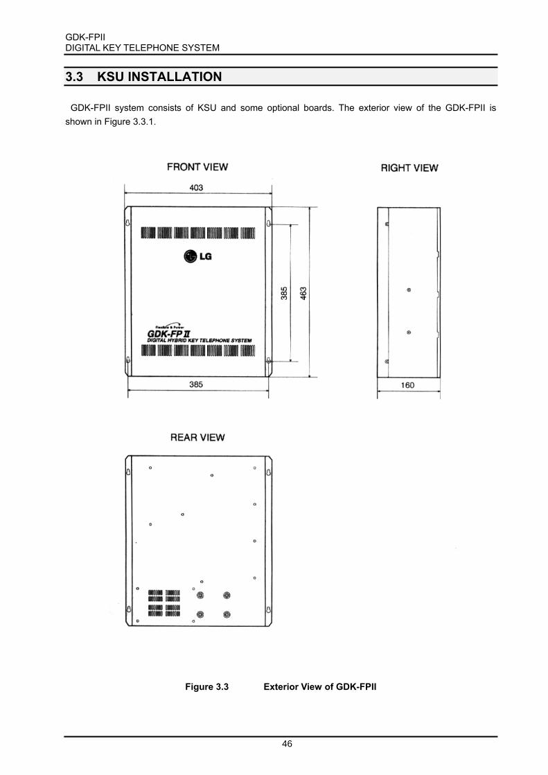
GDK-FPII DIGITAL KEY TELEPHONE SYSTEM
46
3.3 KSU INSTALLATION GDK-FPII system consists of KSU and some optional boards. The exterior view of the GDK-FPII is
shown in Figure 3.3.1.
Figure 3.3 Exterior View of GDK-FPII

GDK-FPII DIGITAL KEY TELEPHONE SYSTEM
47
3.3.1 Mounting KSU The KSU is a metal frame cabinet designed for wall-mounting. Employing the KSU mounting template
provided with the KSU, mark the location of the four screws to mount the KSU. Again, the KSU must not be mounted on a masonry or dry-wall surface, in this case a wooden back-board is required, refer to paragraph [Back-Board Installation]. The distance between mounting holes and the position of mounting holes is shown in Figure 3.3.1.
The KSU is mounted with four #10 or larger, 1.5 inch or longer screws. At first, drill pilot holes in the four locations marked, insert the screws and tighten leaving about 0.5 inch exposed. Mount the KSU on the screws and tighten the screws securely.
Figure 3.3.1 KSU MOUNTING HOLES & INSTALLATION LAYOUT

GDK-FPII DIGITAL KEY TELEPHONE SYSTEM
48
3.3.2 RGU Installation The Ring Generator Unit is needed in KSU if 4SLI or SLIB is installed for using single line telephone, to
provide ringing power and Message Wait Source power. The RGU-EX is mounted on the right bottom side of the KSU with two screws and is connected to the Main Board Unit(MBU) with a CN5(PCB lettering) connector. (See Figure 3.3.2)
A cable for connecting between RGU and MBU is provided with RGU in the same package.
Figure 3.3.2 Ring Generator Unit Installation
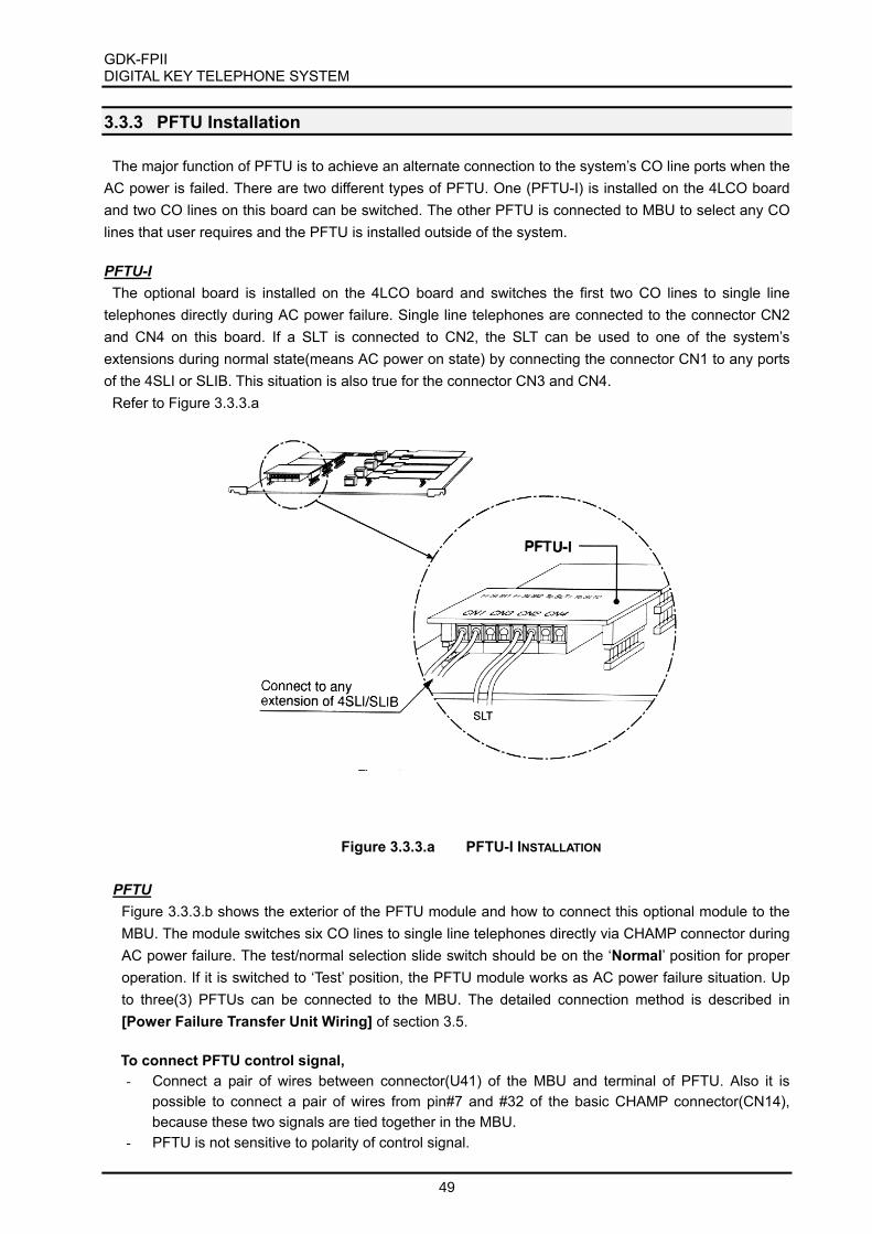
GDK-FPII DIGITAL KEY TELEPHONE SYSTEM
49
3.3.3 PFTU Installation The major function of PFTU is to achieve an alternate connection to the system’s CO line ports when the
AC power is failed. There are two different types of PFTU. One (PFTU-I) is installed on the 4LCO board and two CO lines on this board can be switched. The other PFTU is connected to MBU to select any CO lines that user requires and the PFTU is installed outside of the system.
PFTU-I
The optional board is installed on the 4LCO board and switches the first two CO lines to single line telephones directly during AC power failure. Single line telephones are connected to the connector CN2 and CN4 on this board. If a SLT is connected to CN2, the SLT can be used to one of the system’s extensions during normal state(means AC power on state) by connecting the connector CN1 to any ports of the 4SLI or SLIB. This situation is also true for the connector CN3 and CN4.
Refer to Figure 3.3.3.a
PFTU Figure 3.3.3.b shows the exterior of the PFTU module and how to connect this optional module to the MBU. The module switches six CO lines to single line telephones directly via CHAMP connector during AC power failure. The test/normal selection slide switch should be on the ‘Normal’ position for proper operation. If it is switched to ‘Test’ position, the PFTU module works as AC power failure situation. Up to three(3) PFTUs can be connected to the MBU. The detailed connection method is described in [Power Failure Transfer Unit Wiring] of section 3.5. To connect PFTU control signal, - Connect a pair of wires between connector(U41) of the MBU and terminal of PFTU. Also it is
possible to connect a pair of wires from pin#7 and #32 of the basic CHAMP connector(CN14), because these two signals are tied together in the MBU.
- PFTU is not sensitive to polarity of control signal.
Figure 3.3.3.a PFTU-I INSTALLATION

GDK-FPII DIGITAL KEY TELEPHONE SYSTEM
50
Connecting Wire; - AWG #22 ~ AWG #26 (diameter : about 0.6mm ~ 0.4mm) - Length : Max. 10 meters ~ 1 m ~ 1.5 m (recommended)
Note : The installer can adjust the diameter and length of above wires depending on the site condition.
a) Exterior of the PFTU Module
b) PFTU Installation
Figure 3.3.3.b PFTU Installation
3.3.4 KSU Grounding Before connection to the mains supply, the GDK system must be earthed in conformance with
the appropriate IEE requirements. Earthing is required for user safety and also to minimize EMC interference.
CN14
PFTU
U41
CN15 MBU
NORMAL
TEST
pin#7 & #32 OR
AWG 24

GDK-FPII DIGITAL KEY TELEPHONE SYSTEM
51
To ensure proper system operation and for safety purpose, a good earth ground is required. A metallic
COLD water pipe usually provides a reliable ground. Carefully check that the pipe does not contain insulated joints that could isolate the ground path. If insulated joints exist, another earth ground source should be used or, if allowed, the joints may be bridged.
A separate conductor should be used between the ground source and the KSU, which confirms to the appropriate national or local electrical codes. AGW #14 or larger copper wire is recommended. The wire should be kept as short as possible, it is recommended that the wire be no longer than 8 meters (about 25 feet).
3.3.5 PSU Installation
The Power Supply Unit(PSU) provides the power for the system boards and telephones, converting the AC voltage input to appropriate DC voltages.
The PSU is basically installed when delivering the system. But if PSU is replaced with new one, assure that the AC power cord is NOT plugged into the AC outlet before installing new one.
Note: 1. There are 2 kinds of PSUs, PSU which is a linear type of Power supply Unit, and PSU2 which is
a SMPS. The production of PSU (linear) has been officially stopped after replacing with PSU2(SMPS) in the 1st half of 1999.
2. Following Figure 3.3.3.a shows PSU2 (SMPS). 3. Refer to the APPEDIX C for the installation of PSU (linear). 4.
Figure 3.3.5.a PSU2 without PSU cover

GDK-FPII DIGITAL KEY TELEPHONE SYSTEM
52
After the PSU installation, assemble the cover with three(3) screws. The cover assembling method is shown in Figure 3.3.5.b.
Figure 3.3.5.b PSU2 Cover Assembly

GDK-FPII DIGITAL KEY TELEPHONE SYSTEM
53
3.4 PCB INSTALLATION
3.4.1 PCB Handling & General Installation All boards should not be installed or removed with power applied.
Power must be turned off prior to insertion or removal of the PCB. The system PCBs contain digital circuitry which, while extremely reliable, can be damaged by
exposure to excessive static electricity. When handling PCBs, a grounded wrist strap should be used to protect the boards from static discharges. Also, use common sense when handling the PCBs. For example, do not place a PCB in locations where heavy objects might fall on the PCB and damage components.
To insert a PCB, hold the PCB on the mounting knobs and, with components side facing up, insert the
card into the system’s card edge connector firmly and tighten with screw(s). To remove a PCB, reverse the procedure. Installation method of PCB is shown in Figure 3.4.1.a.
Figure 3.4.1.a PCB Installation

GDK-FPII DIGITAL KEY TELEPHONE SYSTEM
54
There are 7 slots in the GDK-FPII system to extend or modify the system configuration. But, there are some restrictions for optional board installation. Note that the system can not operate properly with wrong installation. The most upper slot (slot #1) is reserved for DVIB, STIB or WTIB, the next slot(slot #2) is reserved only for 4SLI board, the next slot(slot #3) is reserved for one of 4SLI, 2BRI, or PRI boards and the next four(4) slots(slot #4~7) are universal slots.
To summarize, see the following Table 3.4.1.a and Figure 3.4.1.b.
Slot No. Cards Remarks
SLOT 1 DVIB, STIB, WTIB Option cards with own CPU SLOT 2 4SLI Fixed slot for 4SLI board SLOT 3 4LCO, 2BRI, PRI Fixed slot for 4LCO or 2BRI or PRI SLOT 4 SLOT 5 SLOT 6 SLOT 7
LCOB, AC15, BWDIDB, STIB,
SLIB, DTIB, ETIB, DVIB, WTIB, TLIB
Universal Slot *Not allow PRI, 2BRI, 4LCO, 4SLI
Table 3.4.1 Table for Option Cards Installation When the system power is on, the default slot assignment is automatically redefined according to board
installation status. (For this, the switch pin #1 and #4 of the SW1 in MBU should be set to ON position.) And it can be modified by user’s needs.
Insert a short pin when PLLU2 is not installed.
SLOT 1 (DVIB/STIB/WTIB)
SLOT 2 (4SLI)
SLOT 3 (4LCO/2BRI/PRI)
SLOT 5 (Universal Slot)
SLOT 4 (Universal Slot)
SLOT 7 (Universal Slot)
SLOT 6 (Universal Slot)
PSU
RGU -EX
MBU
CN16
CN15
CN14
MEMUor
SMEMU
PLLU2
MODU
SIU(1)
SIU(2)
U41
CN18
CN21
For external PFTU
Insert a short pin when SIU(2) is installed
Figure 3.4.1.b Slot Assignments

GDK-FPII DIGITAL KEY TELEPHONE SYSTEM
55
3.4.2 MBU Installation The MBU is installed in the KSU in default. It is comprised of main processor, six(6) digital terminal
interface circuits, seven(7) card slots for optional boards, memory, real-time clock circuit and data communication circuit which transmits and receives to/from other cards. The MBU may be equipped with four daughter boards; a MEMU for RAM expansion, a SMEMU for the function of QSIG, TAPI and/or PC-Attendant, a MODU for remote access to the system, a PLLU2 for system synchronization and a SIU for serial data transmission. Refer to Figure 3.4.2.a
It should be noted that two SIU boards can be installed when the MODU is NOT installed, and to
install a SIU in the position of SIU(2), an option jumper pin contained in the SIU package should be inserted between pin #1 and pin #2 of MODU connector (CN21) as shown in Figure 3.4.1.b and 3.4.2.5.
Figure 3.4.2.a MBU, MODU, MEMU, SIU, and PLLU2 installation

GDK-FPII DIGITAL KEY TELEPHONE SYSTEM
56
Lithium Battery The MBU contains a lithium dry-cell to keep the memory contents and real-time clock functions during
power failure. The battery is soldered to the MBU, and connected circuitry by an on/off DIP switch (SW3). So the DIP switch knob must be ON position before installing MBU. Refer to Figure 3.4.2.b.
“ CAUTION : Danger of explosion if battery is incorrectly replaced. Replace only with the same
or equivalent type recommended by the manufacturer. Dispose of used batteries according to the manufacturers instruction.”
System Clock Connection without PLLU2 It is important that a shorting trap (option pin) should be inserted to connect the pin #12 and #13 of the
connector CN18(See Figure 3.4.1.b and 3.4.2.c) in the MBU for proper operation when the PLLU2 is NOT installed. Refer to the clause of PLLU2 Installation.
Figure 3.4.2.b Memory Back-Up switch setting
Figure 3.4.2.c System Clock connection without PLLU2

GDK-FPIIDIGITAL KEY TELEPHONE SYSTEM
57
Function of SW1The MBU also has an four-position DIP switch, SW1. The function of each switch position is as
followings:Default setting: All ON position
Switch Function ON OFF
1 Administration Programming Access Enable Disable
2 Trace Control (The purpose of testing software) Disable Enable3 SMDI (Simplified Message Desk Control –Voice Mail ) SMDI OFF SMDI ON
4 Database default on power up Enable Disable
Table 3.4.2 The function of each pole of SW2
Once the database has been initialized, switch 4 should be placed in the OFF position to protect thedatabase in the memory. Before programming the system, switch 4 should be placed in ON position.Then, the system program initializes the system database to default value when the system power is on.Refer to Figure 3.4.2.b.
Function of various switches and connectors
Switch/Connector Functions Remark
SW2 CPU Reset
SW3 Lithium Battery ON/OFF switchCN5 RGU connection
CN6 DC Power connection
CN7~CN13 Function Board Connection for slots 1~7CN14 Basic Port Connection including Relay contacts For MBU, Slot No. 2
CN15 Analog CO line Connection
CN16 Expansion Port Connection For Slot No. 3~7CN17,CN18 PLLU2 connection ISDN 1)
CN19 SIU(2) connection System Access 2)
CN24 SIU(1) connection System AccessCN20, CN21 MODU connection 2)
CN22,23 MEMU or SMEMU connection
CN41 PFTU control signal connectionPJ1 RCA Jack for the external paging
PJ2 RCA Jack for the external music sourcel Note
1) When ISDN board is installed, PLLU2 should be installed. Otherwise there is no necessity forinstalling PLLU. If PLLU is not installed, the shorting trap (short pin) should be locatedbetween contacts 12 and 13 of CN18.The shorting trap (short pin) is installed on above position when the board delivered.
2) It is possible to use one of both MODU and SIU(2). If the SIU is installed on SIU(2) position,contacts 1 and 2 of CN21(connector for MODU) should be short.The shorting trap (short pin) is installed on above position when the board delivered.

GDK-FPIIDIGITAL KEY TELEPHONE SYSTEM
58
Function of LED
LED Function Status Remark
LED1 Display system software operation Turn ON/OFF at every 100 msec
LED2 Display event processing Turn ON during event processingLED3 Display task changing
(software testing purpose)Turn ON/OFF in toggle when thesoftware task is chaging.
LED4 Basic Digital Keyset In-use LED ON: At least one port is busy.OFF: all ports are idle
Check Points- The DIP switch, SW3 should be turned ON position to protect system data in the case of a
power fail.
- The 4th pole of SW1 should be OFF to protect the variety features by Admin programming
after the system power up and initialization. See Table 3.4.2
When the system power is on, the boards in slots will be automatically detected if the 4th pole ofSW1 is set to ON position.
- The pin #12 and #13 of the connector CN18 in the MBU should be shorted with a shorting
trap (short pin) for proper operation when the PLLU2 is NOT installed. Refer to the clause
3.4.2.3 PLLU Installation.
- Add-on boards: MEMU, SMEMU, PLLU, MODU. SIU
3.4.2.1 MEMU Installation
The MBU may be equipped with MEMU for memory expansion. Before power on, install MEMU asrequired, refer to Figure 3.4.2.a. The MEMU has a lithium dry-cell and SW1 must be set to ON position toprotect the database in the memory, before power on.
l Note:- If MEMU is newly installed during operation, then the SMDR recorded in the basic memory of
MBU before MEMU installation will be lost.- If MEMU is replaced with SMEMU during operation, the database will be lost. So it is
recommended that the database is downloaded to PC before replacement, and unloaded afterreplacement.
The MEMU should be installed on MPB through the dual line connectors, CN22 and CN23 of MBU, sorecommend visual inspection of the connecting state between MBU and MEMU after installing it on MBU.
3.4.2.2 SMEMU Installation
The MBU may be equipped with SMEMU for the memory expansion and the QSIG, CTI, PC-ATTNfeatures. Before installing the GDK-FPII, install SMEMU if required, refer to Figure 3.4.2.a. The SMEMUhas a lithium dry-cell and SW1 must be set to ON position to protect the database in the memory, beforepower on.
The SMEMU should be installed on the position of MEMU on MBU.

GDK-FPII DIGITAL KEY TELEPHONE SYSTEM
59
Note: - If SMEMU is newly installed during operation, then the SMDR recorded in the basic memory of
MBU before SMEMU installation will be lost. - If MEMU is replaced with SMEMU during operation, some database will be lost. So it is
recommended that the database is downloaded to PC before replacement and unloaded after replacement.
- If you want to use the QSIG, CTI, PC-ATTN features, the software package 99A version should be required.(See the SMEMU in section 2)
The SMEMU should be installed on MBU through the dual line connectors, CN22 and CN23 of MBU, so
recommend visual inspection of the connecting state between MBU and MEMU after installing it on MBU.
3.4.2.3 PLLU2 Installation The PLLU2 board should be installed on the MBU to use the ISDN interface board such as 2BRI, PRI
and STIB. If PLLU2 is not installed, a short pin should be used to connect the pin #12 and #13 of the connector CN18 (See Figure 3.4.2.c) in the MBU for proper operation.
3.4.2.4 MODU Installation The MODU is used for remote access the system for system maintenance and PC based administration
function. Refer to Figure 3.4.2.a. If MODU is installed, SIU(2) should be removed from the system.
3.4.2.5 SIU Installation
The SIU board is used for system maintenance, PC based Admin, SMDR print and SMDI. The system supports up to two SIU boards when the MODU is not installed. The installation method is shown in Figure 3.4.2.5.
It should be noted that two SIU boards can be installed when the MODU is NOT installed, and an option jumper pin packed with the SIU should be inserted between pin#1 and pin#2 of MODU connector(CN21) of the MBU.
a) When 1 SIU is installed

GDK-FPII DIGITAL KEY TELEPHONE SYSTEM
60
3.4.3 Extension Board Installation The system can be equipped with any combination of the extension boards; DTIB, ETIB, 4SLI, SLIB,
and WTIB. The WTIB can be installed in the most upper slot (slot #1) and the universal slots(slot #4~7), the 4SLI board can be only installed in the next slot(slot #2), DTIB, ETIB, SLIB, and WTIB can be in the universal slots (slot #4~7). See the clause 3.4.1.
3.4.3.1 DTIB Installation The DTIB provides 6 interface circuits for normal type or 2B type digital terminals. All the interface
circuits can support 2B format of digitized voice data. The connection between DTIB and digital terminals are performed through RJ21 type connector (CN16) on the MBU. The exterior of the board is shown in Figure 3.4.3.1.
Function of LEDs
LED Function Remark LD1 The status of ports. (ON: in use, OFF: idle)
In GDK-FPII system, all Digital Terminal Interfaces are capable of accommodating 2B-channel operation.
LDK-30DS with 2B-module and secondary terminal can be connected to every port of DTIB or MBU. See clause 2.4.13.3 2B-module and clause 2.4.13.4 GDK-PC PHONE in section 2 for more details regarding 2B-module and CTI module.
b) When 2 SIUs are installed
Figure 3.4.2.5 SIU Installation

GDK-FPII DIGITAL KEY TELEPHONE SYSTEM
61
Figure 3.4.3.1 DTIB layout
The DTIB board can be installed on any slot of universal slots (slot #4~7). The Maximum 4 boards can be installed in a system.
3.4.3.2 ETIB Installation
The ETIB provides 6 interface circuits for analog type electronic key telephones. The connection between ETIB and electronic terminals are performed through RJ11 type jacks on the board. The exterior of the board is shown in Figure 3.4.3.1.
Function of LED
LED Function Remark LED1 The status of ports. (ON: in use, OFF: idle)
Function connector
Connector Function Remark MJ1~MJ6 RJ11 type jack for terminal connection. See clause 3.4.5
Figure 3.4.11 ETIB layout
The ETIB board can be installed on any slot of universal slots (slot #4~7). The Maximum 4 boards can be installed in a system.

GDK-FPII DIGITAL KEY TELEPHONE SYSTEM
62
3.4.3.3 SLIB/4SLI Installation There are two kinds of single line telephone interface boards, one is 4SLI and the other is SLIB. The
4SLI card provides four(4) interface circuits for SLT and the SLIB card provides six(6) interface circuits for SLT. The 4SLI/SLIB can be optionally equipped with a DTRU for DTMF detect and a MSGU for control the message wait lamp of the SLT. And an RGU is required for ringing SLTs.
The exterior of them are shown in Figure 3.4.3.3. The major difference is shown in below Table 3.4.3.3. The 4SLI board can be installed on slot #2 only, but the SLIB can be installed any one of universal slots
(slot #4~7).
Board Slot Interfaces circuits Add-on Boards 4SLI Slot # 2 4 DTRU, MSGU SLIB Slot # 4~7 6 DTRU, MSGU
Table 3.4.3.3 Difference between 4SLI and SLIB
Function of LED
LED Function Remark LED1 The status of ports. (ON: in use, OFF: idle)
Function of various connectors
Connector Function Remark CN1 and CN2 DTRU connection 1) CN3 and CN4 MSGU connection 1) Note:
1) If you want Message Waiting function on 4SLIB or SLIB, GDK-100 MSGU should be installed on 4SLI and SLIB.
2) The distance between SLIB and SLT: see Table 2.3.4
a) 4SLI Card

GDK-FPII DIGITAL KEY TELEPHONE SYSTEM
63
b) SLIB Card
Figure 3.4.3.3 Exterior of the 4SLI/SLIB
3.4.3.4 DTRU Installation
A DTRU contains 2 DTMF receiver circuits. Each receiver of DTRU is time-shared under the control of the system software, as a system resource regardless its position.
Board The position of Installation The quantity of receivers Marking on PCB DTRU 4SLI, SLIB, 4LCO, LCOB, TLIB,
BWDIDB 2 DTMF receivers DTRU of GDK-34/36
The System is capable of supporting DTMF receivers up to 14. 2 DTMF receivers are basically laid out on MBU. Take a cautious attitude in installing DTRU on the boards because DTRU contains the
connectors without the connection guide, otherwise DTRU may be damaged by wrong connection.
3.4.3.5 MSGU Installation A message waiting unit can be optionally installed on a SLT interface board to light a message waiting
lamp in the SLT connected.
Board The position of Installation The quantity of circuits The line voltage MSGU 4SLI, SLIB 6 circuits +24Vdc Signal voltage: 90~100Vdc
3.4.4 Analog CO Line Board Installation There are several types of analog CO line boards available. These boards include the 4LCO and LCOB.
Additional CO interface boards such as AC15, TLIB and BWDIDB may be available for support of local market conditions and regulatory requirements.
The slot No.3 to No. 7 in the system, which are available for use as a CO Line board, are wired to 4 or 2 CO Lines at the CN15 connector through the MBU. The connection matrix is shown in section 3.5. Analog CO line wiring; contact assignments of RJ21 type male connector (CN15).

GDK-FPIIDIGITAL KEY TELEPHONE SYSTEM
64
3.4.4.1 LCOB/4LCO Installation
There are two kinds of available analog CO line interface (Loop-start technology) boards. One is 4LCOand the other is LCOB. The exteriors of them are shown in Figure 3.4.4.1.
The major difference is shown in below Table 3.4.2. The 4LCO board can be installed on slot #3 onlyand the LCOB can be installed on slot #4~7(universal slot).
All these two boards provide four(4) Loop Start lines, can be optionally equipped with Call MeteringUnit(CMU) for monitoring call charge and a Call Progress Tone Unit(CPTU) for monitoring call progresssignals and a DTMF Receiver Unit(DTRU) for detecting DTMF for single line devices. A CMU should beprovided for each Loop Start CO line which requires call metering function. In addition, the appropriatetype of CMU should be employed. Each CPTU contains two tone detection circuits that are time sharedunder software control. These detectors are used to support several features including ACNR. If suchfeatures are to be used, it is recommended that CPTU be installed for every 4LCO/LCOB. According tosensitivity of tone detector, two types of CPTUs(CPTU/A, CPTU/B) are available. CPTU/A has wide tonedetection range(305Hz~640Hz) and CPTU/B has narrow tone detection range (350Hz, 620Hz, 440Hz,480Hz±1%). If required, install the CMUs, a CPTU and a DTRU, on the 4LCO/LCOB.
And an optional PFTU-I can be installed on the 4LCO only. This module supports power failure transferfunction of the first 2 CO lines of the 4LCO board.
Board Slot Interface Circuits. Option Boards
4LCO SLOT #3 4 CPTU, CMU, DTRU, PFTU-I
LCOB SLOT #4~7 4 CPTU, CMU, DTRU
Table 3.4.2 Differences between 4LCO and LCOB
Function of LED
LED Function RemarkLD1 The status of line 1, ON: in use, GreenLD2 The status of line 2, ON: in use, Green
LD3 The status of line 3, ON: in use, Green
LD4 The status of line 4, ON: in use, Green
Function of various connectors
Connector Function Remark
CN1 and CN2 DTRU connection
CN3 and CN4 CPTU connectionCN5 and CN6 PFTU-I connection 4LCO only
CN100 and CN104 The connectors for a CMU on line 1 See Note
CN101 and CN105 The connectors for a CMU on line 2 See NoteCN102 and CN106 The connectors for a CMU on line 3 See Note
CN103 and CN107 The connectors for a CMU on line 4 See Notel Note:
1. The pin #6 and #7 of CN104, CN105, CN106 and/or CN107 should be shorted by shortingtraps (short pin) when CMU12(12 KHz meter pulse) including CMU12PR or CMU16(16 KHzmeter pulse) is not installed on the interface circuit(s). Otherwise the receiving voice path ofthe related line will be open.

GDK-FPII DIGITAL KEY TELEPHONE SYSTEM
65
2. The 0 ohm resistors are usually mounted on R168-R171 of LCOB for the countries using only CMU PR(Polarity Reversal) and/or 50L(50 Hz longitudinal). If these CMUPR, CMU50L or CMU50PR are not installed on any CO interface circuit neither R168-R171 are mounted on LCOB, the pin #6 and #7 of CN104, CN105, CN106 and/or CN107 should be also shorted by shorting traps (short pin) on the related interface circuit.
3. CN104/R168 are on the 1st interface circuit, CN105/R169 on the 2nd interface circuit, CN106/R170 on the 3rd interface circuit and CN107/R171 on 4th interface circuit.
4LCO can be only installed in slot No. 3. LCOB can be only installed in the universal slots (No. 4 to 7), and the maximum four LCOBs can
be installed in a system. Add-on boards: DTRU, CPTU/A, CPTU/B, CMU, PFTU-I (4CLO only).
a) 4LCO Card
b) LCOB Card
Figure 3.4.4.1 4LCO/LCOB Board

GDK-FPIIDIGITAL KEY TELEPHONE SYSTEM
66
3.4.4.2 AC15 Board Installation - UK
The AC15 board provides 2 Tie interface circuits, each line supports AC15a signaling.It is designed to comply with the UK specification and application, so it may not suitable for the other
national specification and/or application.
Function of LED
LED Function RemarkLD1 The status of line 1, ON: in use
LD2 The status of line 2, ON: in use
The AC15 board can be installed in any of slot No. 4~7.
The maximum four AC15 boards can be installed in a system.
3.4.4.3 TLIB Installation - Korea
The TLIB provides 2 analog E&M interfaces. It can support type I and V of 2-wire E&M.It is designed to comply with the Korean specification and application, so it may not suitable for the other
national specification and/or application.
Function of LED
LED Function Remark
LD1 The status of line 1, ON: in useLD2 The status of line 2, ON: in use
Function of various connectors
Connector Function Remark
CN1 and CN2 DTRU connection
Line mode selection
E&Mconnectors
Type V Type I
Ring Down
JP9,CN12 short pin no. 1-2 short pin no. 1-2 short pin no. 2-3JP10,CN11 short pin no. 2-3 short pin no. 1-2 Don’t care
l Note: TLIB mainly supports 2-wire E&M type V. It is recommended to set 2 wire E&M Type V.
Check pointTLIB can be installed in any of slot No. 4~7.
The maximum four TLIBs can be installed in a system.
When installing E&M line, It is important to check the type of the opposite line and jumper
position.
Add-on board: DTRU

GDK-FPIIDIGITAL KEY TELEPHONE SYSTEM
67
3.4.4.4 BWDIDB Installation – New Zealand
The BWDIDB provides 4 analog both-way DID interfaces. Each line supports Outgoing/Incoming call.It is designed to comply with New Zealand specification and application, so it may not suitable for the
other national specification and/or application.
Function of LED
LED Function RemarkLD1 The status of line 1, ON: in use
LD2 The status of line 2, ON: in use
LD3 The status of line 3, ON: in useLD4 The status of line 4, ON: in use
Function of various connectors
Connector/Switch Function Remark
CN1 and CN2 DTRU connectionCN3 and CN4 CPTU/A or CPTU/B connection
BWDIDB can be installed in any of slot No. 4~7.The maximum four BWDIDBs can be installed in a system.
Add-on boards: DTRU, CPTU/A, CPTU/B
3.4.5 ISDN Board Installation
There are 3 kinds of ISDN boards such as PRI, 2BRI, and STIB are available. PRI and 2BRI can be onlyinstalled in slot No.3, and STIB in slot No.1, 4~7.
Each ISDN board contains RJ45 type jack on boards themselves.
3.4.5.1 ISDN 2BRI (Basic Rate T interface) Installation
The 2BRI card provides 2 interface circuits of BRI(Basic Rate Interface) format digital CO interface. Forusing this board, the PLLU2 board should be installed on the MBU. If more than one ISDN board isrequired, some special cable should be used for clock signal control. CN1 and CN2 are used to controlthe clock signal when multi-ISDN boards are installed. Refer to [Clock Control Cable Wiring] of section3.5.
Function of LED
LED Function Status RemarkLD1 The status of Line 1 Red: Error, Green: Synchronized
LD2 The status of Line 2 Red: Error, Green: Synchronized
Function of SW1; default -all OFF when delivering the board
Pole Function ON OFF Remark1 Loop Back Mode (for testing purpose) Enable Disable
2 Not used - -
3 Trace Enable Disable Note 14 Trace: for the purpose of Lab. test Enable Disable Note 1

GDK-FPIIDIGITAL KEY TELEPHONE SYSTEM
68
l Note:1. These two poles are for the purpose of developing, testing and maintaining 2BRI.2. The TEI mode of 2BRI is set to Fixed TEI as default.
3. All poles should be OFF during normal operation. Especially the pole 1 should be OFF.
Function of various connectors
Connector Function RemarkCN1 Clock control OUT Note 1
CN2 Clock control IN Note 1l Note:
1. CN1, CN2: They are used to control the reference clock signal when multi-ISDN boards areinstalled. See [Clock Control Cable Wiring] in section 3.5.
The line connector and terminating resistors
Terminating ResistorsLine No RJ45 type jackSwitch All ON All OFF
Line 1 MJ1 CN3 terminating open
Line 2 MJ2 CN4 terminating open
l Note1. Two terminating resistors are required on a line, one for TX pair and the other for RX pair,
for proper operation. Two connectors of CN3 and CN4 should be set to the ON position toterminate two terminating resistors on a line.
2. Terminating resistors and selectable switches are introduced only on PCB issue 2 or later,
but not on PCB issue 1. So if you use 2BRI issue 1, the external terminating resistors are
required. For the external termination, you can get the terminating unit locally or use GDK-
162/100 TERM, which is the terminating unit with 4 P-to-P connection provided by LGE.
Figure 3.4.5.1.a The connection of Terminating Resistors on 2BRI issue 2
Ter. Res.
LINE 1
CN3
OFF
ON
OFF
Ter. Res.
LINE 2
CN4
MJ1 MJ2
RJ45 type Jack
ON

GDK-FPII DIGITAL KEY TELEPHONE SYSTEM
69
Figure 3.4.5.1.b 2BRI Board
Check Points 1. 2BRI boards can be installed only in the slot No. 3. 2. The PLLU2 MUST be installed on MBU. 3. The 2BRI supports Fixed TEI. 4. The RX and TX pairs of line should be correctly connected to the TX and RX pairs of NT1. 5. The clock control cable should be connected to the proper position when multi-ISDN
cards are installed in a system. See section 3.5. 6. Terminating resistors on the line. (CN3 and CN4) 7. SMEMU MUST be required on MBU for QSIG operation. See SMEMU in section 2.
3.4.5.2 ISDN STIB (Basic Rate S/T Interface) Installation The STIB provides 2 interface circuits of BRI(Basic Rate Interface) format ‘S’ and ‘T’ mode interface.
The operating mode selection is performed by setting the short pins and DIP switch to associate position. The ‘S’ mode is used for connecting the ISDN terminal and the ‘T’ mode is used for connecting the ISDN CO line. For using this board, the PLLU2 board should be installed on the MBU. If more than one ISDN board is required, some special cable should be used for clock signal control. CN1 and CN2 are used to control the clock signal when multi-ISDN boards are installed. Refer to [Clock Control Cable Wiring] of section 3.5. Function of LED
No Function Status Remark LD1 The status of Line 1 Red: Error, Green: Synchronized LD2 The status of Line 2 Red: Error, Green: Synchronized
Function of SW1: default - all OFF when delivering the board
Pole Function ON OFF Remark 1 Not used - - 2 TEI Fixed TEI Automatic TEI Note 1, 2 3 Layer 2 trace Enable Disable Note 3 4 Layer 3 trace Enable Disable Note 3

GDK-FPIIDIGITAL KEY TELEPHONE SYSTEM
70
l Note:1. The function of 2nd pole has been implemented in firmware version 1.1 or later.2. This is set to OFF position as default, therefore it is important to note that 2nd pole is
set to the proper position after checking the type of TEI in your country.
3. These two poles are for the purpose of developing and maintaining STIB.
Function of various connectors
Connector Function Remark
CN1 Clock control OUT Note 1CN2 Clock control IN Note 1
CN104 Serial interface connector Note2l Note
1. CN1, CN2: They are used to control the reference clock signal when multi-ISDN boards areinstalled.See [Clock Control Cable Wiring] on section 3.5.
2. CN104: Trace for the purpose of development and maintenance. The external module for RS 232C serial interface should be required for trace.See GDK-TRC1 in section 2.
The line mode selection (S or T interface setting)
S/T mode selection Changing the contact assignmentsLine No RJ45type Jack Switch All to “T “ All to “S” Connector All to “T “ All to “S”
Line 1 MJ1 SW2 T S CONN1 T S
Line 2 MJ2 SW3 T S CONN2 T S
l Note:1. The setting method of S/T mode selection switches and connectors: default -all T position
when delivering the board.Each line interface can be used for T interface or S interface with different operation interface.If necessary, the S/T selection switch/connector of SW2/CONN1 or SW3/CONN2 can berespectively set to the T or S position.
2. Each line can be selected to T or S interface according to the needs.3. After setting all lines respectively, the slot(s) of STIB must be assigned as CO slot(s) and STA
slot(s) together in Admin field 02 for the proper operation of STIB. See the clause 4.2 and theProgramming Manual.
The line termination / the power feed to TE
Terminating Resistors(Two poles in the right side )
Power Feed to TE(Two poles in the left side )
Line No
Connector Set to ON Set to OFF Connector Set to S Set to T
Line 1 CONN3 terminating open CONN3 Feed open
Line 2 CONN4 terminating open CONN4 Feed open
l Note:1. Two poles in the right side of CONN3/CONN4 should set to the ON position to terminate two
terminating resistors on a line.2. Two poles in the left side of CONN3/CONN4 should set to the S position to the power into
ISDN terminal.

GDK-FPII DIGITAL KEY TELEPHONE SYSTEM
71
Check Points
1. STIB can be installed in any of the slot No. 1, 4~7. 2. PLLU2 MUST be installed on MBU. 3. Each interface should be set to the correct type, T or S with S/T selection connectors,
according to the needs of user. And the RX and TX pairs of line should be correctly connected to the TX and RX pairs of NT1 or TE according to the interface type of each line.
4. Terminating resistors on the line. 5. The 2nd pole of SW1 should be set to the proper position according to the type of TEI. 6. The clock control cable should be connected to the proper position when multi-ISDN
cards are installed in a system. See section 3.5. 7. SMEMU MUST be required on MBU for QSIG operation. See SMEMU in section 2.
Figure 3.4.5.2.b STIB Installation
Figure 3.4.5.2.a The setting method for termination and Power feeding
If the user want to use on-board terminating resistors, the right two short pins of CONN3(forLine1)/CONN4(for Line 2) should be placed on the ‘ ON ‘ position. And If the interface is in “S”mode operation and power feed to external ISDN terminal is not required, the left two short pins ofCONN3(or CONN4) should be placed on the “T” position. On PCB issue 1(6870N01591), the Markings, POWER and TER.RES. may different from above.But the physical tracks are the same as above.
Power is not fed
Power is fed
POWER TER.RES
T
S
Termination resistor is not connected. Termination is connected.
CONN3/CONN4
OFF
ON
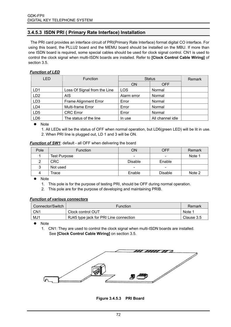
GDK-FPII DIGITAL KEY TELEPHONE SYSTEM
72
3.4.5.3 ISDN PRI ( Primary Rate Interface) Installation The PRI card provides an interface circuit of PRI(Primary Rate Interface) format digital CO interface. For
using this board, the PLLU2 board and the MEMU board should be installed on the MBU. If more than one ISDN board is required, some special cables should be used for clock signal control. CN1 is used to control the clock signal when multi-ISDN boards are installed. Refer to [Clock Control Cable Wiring] of section 3.5.
Function of LED Status LED Function
ON OFF Remark
LD1 Loss Of Signal from the Line LOS Normal LD2 AIS Alarm error Normal LD3 Frame Alignment Error Error Normal LD4 Multi-frame Error Error Normal LD5 CRC Error Error Normal LD6 The status of the line In use All channel idle Note
1. All LEDs will be the status of OFF when normal operation, but LD6(green LED) will be lit in use. 2. When PRI line is plugged out, LD 1 and 3 will be ON.
Function of SW1: default - all OFF when delivering the board
Pole Function ON OFF Remark 1 Test Purpose - - Note 1 2 CRC Disable Enable 3 Not used - - 4 Trace Enable Disable Note 2 Note
1. This pole is for the purpose of testing PRI, should be OFF during normal operation. 2. This pole are for the purpose of developing and maintaining PRIB.
Function of various connectors
Connector/Switch Function Remark CN1 Clock control OUT Note 1 MJ1 RJ45 type jack for PRI Line connection Clause 3.5 Note
1. CN1: They are used to control the clock signal when multi-ISDN boards are installed. See [Clock Control Cable Wiring] on section 3.5.
Figure 3.4.5.3 PRI Board

GDK-FPIIDIGITAL KEY TELEPHONE SYSTEM
73
Check Points1. One PRI board can be installed only in the slot No.3.
2. PLLU2 MUST be installed on MBU.
3. For QSIG operation, SMEMU MUST be required on MBU for QSIG operation. See SMEMU insection 2.
4. The clock control cable should be connected to the proper position when multi-ISDN cards
are installed in a system. See section 3.5.
3.4.6 DVIB (Digitized Voice Interface Board) Installation
DVIB provides system announcement, ACD/UCD announcement, and User Greeting. If necessary, theDMEU(DVU Memory Expansion Unit) or DMEU4 can be installed on DVIB for the expansion of UserGreetings. And, if necessary, the ADPU(ADPCM Unit) can be installed on DVIB for the expansion of useraccess channels.
Function of LED
StatusNo DescriptionON OFF
Remark
LED1 The status of channel 1 In use Idle
LED2 The status of channel 2 In use Idle
LED3 The status of channel 3 In use IdleLED4 The status of channel 4 In use Idle
LED5 The status of channel 5 In use Idle
LED6 The status of channel 6 In use IdleLED7 The status of channel 7 In use Idle
LED8 The status of channel 8 In use Idle
Function of various connectors
Connector Function RemarkCN1 Dummy connector
CN2 Serial interface connector( 4pin) for trace Note 1
CN3 and CN4 ADPU connectionCN5 and CN6 DMEU or DMEU4 connection
CN13 For the purpose of development
PJ1 RCA jack for Audio Input, DVU MOH input BluePJ2 RCA jack for Audio Output. Red
l Note1. CN2: Trace for the purpose of development and maintenance.
The external module for RS 232C serial interface should be required for trace using thisconnector. See GDK-TRC1 in section 2.
2. CN13, PJ2: It is impossible to use them for user access.These connectors are usually used for the purpose of development and production test.Especially, all the pins of CN13 should be open for the normal operation.

GDK-FPII DIGITAL KEY TELEPHONE SYSTEM
74
Function of various switches
Switch Function Remark SW2 SRAM back-up when power interruption or failure ON SW5 For the purpose of development OFF SW6 Not used Note
1. SW2: This is for the purpose of SRAM back-up for ACD/UCD announcement. It should be turned ON during installing the DVU/EDVU, to protect announcements in the case of a power fail.
“ Caution : Danger of explosion if battery is incorrectly replaced. Replace only with the
same or equivalent type recommended by the manufacturer. Dispose of used batteries according to the manufacturers instruction.”
Add-on boards: DMEU, DMEU4, ADPU
Figure 3.4.6 Board Layout and ADPU, DMEU/DMEU4 installation
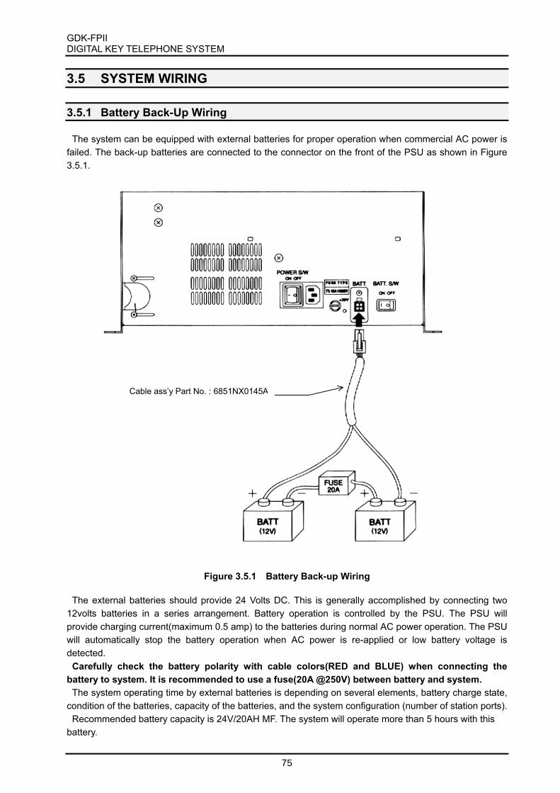
GDK-FPII DIGITAL KEY TELEPHONE SYSTEM
75
3.5 SYSTEM WIRING
3.5.1 Battery Back-Up Wiring The system can be equipped with external batteries for proper operation when commercial AC power is
failed. The back-up batteries are connected to the connector on the front of the PSU as shown in Figure 3.5.1.
Figure 3.5.1 Battery Back-up Wiring The external batteries should provide 24 Volts DC. This is generally accomplished by connecting two
12volts batteries in a series arrangement. Battery operation is controlled by the PSU. The PSU will provide charging current(maximum 0.5 amp) to the batteries during normal AC power operation. The PSU will automatically stop the battery operation when AC power is re-applied or low battery voltage is detected.
Carefully check the battery polarity with cable colors(RED and BLUE) when connecting the battery to system. It is recommended to use a fuse(20A @250V) between battery and system.
The system operating time by external batteries is depending on several elements, battery charge state, condition of the batteries, capacity of the batteries, and the system configuration (number of station ports).
Recommended battery capacity is 24V/20AH MF. The system will operate more than 5 hours with this battery.
Cable ass’y Part No. : 6851NX0145A

GDK-FPIIDIGITAL KEY TELEPHONE SYSTEM
76
3.5.2 RS 232C WIRING on SIU
The SIU has one industry standard 9-pin RS-232C connector. The RS-232C ports are connected by 9-pin “D” connectors as shown 3.5.2. Note that the communication settings are 9600bps, 8 bits data, noparity bit and 1 stop bit.
The SIU(1) position of the MBU provides all the serial communication control signals such as TXD, RXD,CTS, RTS, DSR, DTR and ground. But the SIU(2) position does not provide all these signals and onlyprovides three(3) control signals such as TXD, RXD and ground. For the reason, in case of using twoSIUs, you have to consider this situation and connect carefully for proper operation.
DB-9 connectorfor RS-232Con Terminal
a) SIU wiring on the SIU(1) position of MBU
2
3
4
6
7
8
5
2
3
4
6
7
8
5
TD
RD
DSR
DTR
CTS
RTS
SG
RD
TD
DTR
DSR
RTS
CTS
SG
DB-9 connectorfor the RS-232Cof SIU on SIU(1)
2
3
4
6
7
8
5
3
2
20
6
4
5
7
TD
RD
DSR
DTR
CTS
RTS
SG
RD
TD
DTR
DSR
RTS
CTS
SG
DB-9 connectorfor the RS-232Cof SIU on SIU(2)
DB-25 connectorfor RS-232Con Terminal
Name FunctionTD Transmitted DataRD Received DataRTS Request To SendCTS Clear To SendDTR Data Terminal ReadyDSR Data Set ReadySG Signal Ground
DB-9 connectorfor RS-232Con Terminal
2
3
5
2
3
4
5
TD
RD
SG
RD
TD
SG
DB-9 connectorfor the RS-232Cof SIU on SIU(1)
2
3
6
3
2
6
TD
RD
SG
RD
TD
SG
DB-9 connectorfor the RS-232Cof SIU on SIU(2)
DB-25 connectorfor RS-232Con Terminal
Figure 3.5.2 Pin assignments and wiring of DB25 and DB9 for RS-232C
b) SIU wiring on the SIU(2) position of MBU

GDK-FPII DIGITAL KEY TELEPHONE SYSTEM
77
Note: 1. Protective Ground (Frame Ground) may be used between DTE and DCE(GDK system) for
more stable communication. And it is recommended. In DTEs and DCEs, protective ground (frame ground) is a point which is electrically bonded to the equipment frame. Protective ground (frame ground) is not an interchange circuit in RS232 standard.(EIA/TIA-232-F) If bonding of the equipment frames of the DCE and the DTE is necessary, a separate conductor should be used which confirms to the appropriate national or local electrical codes.
3.5.3 MBU wiring There are three(3) RJ21 type connectors(CN14 ~ CN16) and 2 RCA jacks on MBU for the external line
or devices. There are three(3) RJ21 type connectors(CN14 ~ CN16) in the left most side of the MBU. These connectors are used to connect all ports of the system except ETIB and ISDN line/terminal, such as CO lines, electronic keysets, digital keysets and single line telephones. So, station wiring is performed by these connectors. The method of RJ21 type cable connection is shown in Figure 3.5.3.
The middle one (CN15) is assigned to CO line connection only, and signal lines of this connector are
distributed to slot #3 to slot #7. Refer to [CO Wiring] section.
The cable with RJ21 type male connector is required to connect with terminal or external devices. It is
possible to get the cable locally, or use GDK-162 5MC2 supplied by LGE on the order if necessary.
Figure 3.5.3 Connection Method of RJ21 type connector
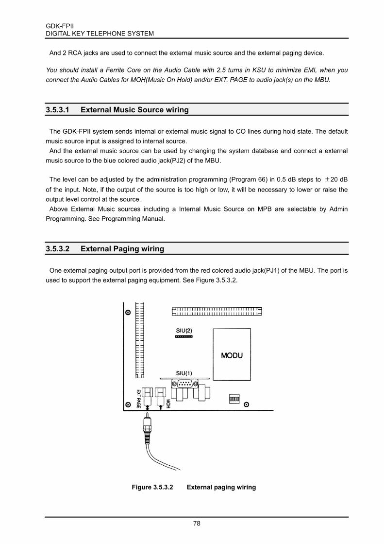
GDK-FPII DIGITAL KEY TELEPHONE SYSTEM
78
And 2 RCA jacks are used to connect the external music source and the external paging device. You should install a Ferrite Core on the Audio Cable with 2.5 turns in KSU to minimize EMI, when you connect the Audio Cables for MOH(Music On Hold) and/or EXT. PAGE to audio jack(s) on the MBU.
3.5.3.1 External Music Source wiring The GDK-FPII system sends internal or external music signal to CO lines during hold state. The default
music source input is assigned to internal source. And the external music source can be used by changing the system database and connect a external
music source to the blue colored audio jack(PJ2) of the MBU. The level can be adjusted by the administration programming (Program 66) in 0.5 dB steps to ±20 dB
of the input. Note, if the output of the source is too high or low, it will be necessary to lower or raise the output level control at the source.
Above External Music sources including a Internal Music Source on MPB are selectable by Admin Programming. See Programming Manual.
3.5.3.2 External Paging wiring One external paging output port is provided from the red colored audio jack(PJ1) of the MBU. The port is
used to support the external paging equipment. See Figure 3.5.3.2.
Figure 3.5.3.2 External paging wiring

GDK-FPIIDIGITAL KEY TELEPHONE SYSTEM
79
3.5.3.3 External Paging Port and General Purpose Relays wiring
One external paging output port is provided from the red colored audio jack(PJ1) of the MBU. The port isused to page outside through external amplifier as a system extension.
And there are two general purpose relays in the MBU and these contacts are connected throughCHAMP connector(CN14) of the MBU. Detailed pin assignment of these contacts are shown in Table3.5.3.6. The dry relay contact can be used to power on/off function for external amplifier. The control ofthese relays are done by system programming.
For example, the following Figure 3.5.3.3 shows how to connect external amplifier with relay andexternal paging port.
3.5.3.4 Relay contacts for general purpose
GDK-FPII supports up to 2 Relay contacts, which can be used for the functions of Loud Control, DoorOpen and so on under the software control. These relay contacts are respectively connected withexternal equipment through 2 pairs of a RJ21 type connector, CN14 on the board.
RLY1: Pin No. 1 and Pin No. 26RLY2: Pin No. 3 and Pin No. 28
External
AmplifierExt. paging output(PJ1 of the MBU)
Pin #1 of CN14
Pin #26 of CN14
RJ21 type connector (CN14)
Figure 3.5.3.3 Example of External Paging Wiring
External DC
Power Supply
MD
F
GDK-FPII MBU
RJ21 type connector, CN14
1
26
Figure 3.5.3.4 An example of Loud Bell wiring

GDK-FPIIDIGITAL KEY TELEPHONE SYSTEM
80
3.5.3.5 Alarm Detection wiring
GDK-FPII MBU provides an external alarm detection input, which can be used to notify to extensionswhen the external switch is on/off. This alarm detection input is provided through a pair of a RJ21 typeconnector, CN14 on the board.
ALARM: Pin No. 12 and Pin No. 37
Close or open detection is programmable by Admin. Programming.
3.5.3.6 Contact Assignments of RJ21 type connector for Basic Connection
The upper one(CN14) and lower one(CN16) are assigned to system’s extension line such as digitalkeysets and single line telephones. Basically the upper most connector(CN14) is used to connect basicsystem resources and basic digital extensions. The upper one’s usage is listed as follows and detailed pinmapping table is shown in Table 3.5.3.6.
The usage of CN14 in the left upper side of MBU is as followings,- 6 ports of digital terminals on the MBU: See the Digital Keyset and Terminal wiring in this section.- 4 ports of SLTs of the 4SLI board on the slot #2: See the Single Line Telephone wiring in this section.- 2 ports of general purpose relay dry contacts- 1 alarm detect port- 1 external PFTU control port; See the PFTU wiring in this section.
MD
F
GDK-FPII MBU
RJ21 type connector, CN14
12
37
Figure 3.5.3.5 An example of External Switch wiring
ExternalSwitch

GDK-FPIIDIGITAL KEY TELEPHONE SYSTEM
81
Table 3.5.3.6 shows the contact assignments of RJ21 type female connector (CN14) on MBU for BasicConnection.
Punch-Down MBU Connector CN14
Block Pin Pair Pin Color-Code Designation
1 1 26 WH/BL RELAY-R11 BL/WH RELAY-T1
3 2 27 WH/OR4 2 OR/WH5 3 28 WH/GN RELAY-R26 3 GN/WH RELAY-T27 4 29 WH/BN8 4 BN/WH9 5 30 WH/SL10 5 SL/WH11 6 31 RD/BL12 6 BL/RD13 7 32 RD/OR PFT-VO14 7 OR/RD PFT-CTL15 8 33 RD/GN16 8 GN/RD17 9 34 RD/BN18 9 BN/RD19 10 35 RD/SL20 10 SL/RD21 11 36 BK/BL22 11 BL/BK23 12 37 BK/OR ALARM-T24 12 OR/BK ALARM-R25 13 38 BK/GN26 13 GN/BK27 14 39 BK/BN28 14 BN/BK29 15 40 BK/SL30 15 SL/BK31 16 41 YL/BL VR-432 16 BL/YL VT-433 17 42 YL/OR VR-334 17 OR/YL VT-3 SLT35 18 43 YL/GN VR-2 Port36 18 GN/YL VT-237 19 44 YL/BN VR-138 19 BN/YL VT-139 20 45 YL/SL DR-640 20 SL/YL DT-6 BL:BLUE41 21 46 VI/BL DR-5 BK:BLACK42 21 BL/VI DT-5 BN:BROWN43 22 47 VI/OR DR-4 OR:ORANGE44 22 OR/VI DT-4 Digital WH:WHITE45 23 48 VI/GN DR-3 Port GN:GREEN46 23 GN/VI DT-3 SL:SLIVER47 24 49 VI/BN DR-2 VI:VIOLET48 24 BN/VI DT-2 RD:RED49 25 50 VI/SL DR-1 YL:YELLOW50 25 SL/VI DT-1
Table 3.5.3.6 Basic Connector (CN14) Wiring
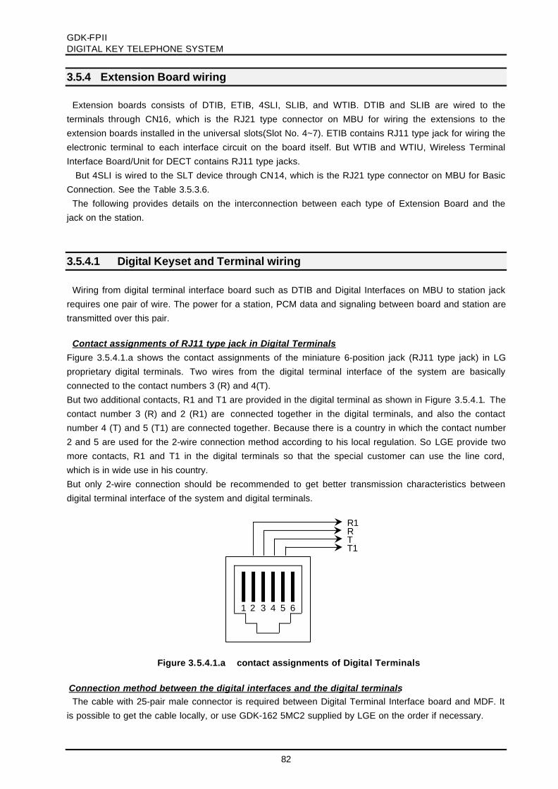
GDK-FPIIDIGITAL KEY TELEPHONE SYSTEM
82
3.5.4 Extension Board wiring
Extension boards consists of DTIB, ETIB, 4SLI, SLIB, and WTIB. DTIB and SLIB are wired to theterminals through CN16, which is the RJ21 type connector on MBU for wiring the extensions to theextension boards installed in the universal slots(Slot No. 4~7). ETIB contains RJ11 type jack for wiring theelectronic terminal to each interface circuit on the board itself. But WTIB and WTIU, Wireless TerminalInterface Board/Unit for DECT contains RJ11 type jacks.
But 4SLI is wired to the SLT device through CN14, which is the RJ21 type connector on MBU for BasicConnection. See the Table 3.5.3.6.
The following provides details on the interconnection between each type of Extension Board and thejack on the station.
3.5.4.1 Digital Keyset and Terminal wiring
Wiring from digital terminal interface board such as DTIB and Digital Interfaces on MBU to station jackrequires one pair of wire. The power for a station, PCM data and signaling between board and station aretransmitted over this pair.
Contact assignments of RJ11 type jack in Digital TerminalsFigure 3.5.4.1.a shows the contact assignments of the miniature 6-position jack (RJ11 type jack) in LGproprietary digital terminals. Two wires from the digital terminal interface of the system are basicallyconnected to the contact numbers 3 (R) and 4(T).But two additional contacts, R1 and T1 are provided in the digital terminal as shown in Figure 3.5.4.1. Thecontact number 3 (R) and 2 (R1) are connected together in the digital terminals, and also the contactnumber 4 (T) and 5 (T1) are connected together. Because there is a country in which the contact number2 and 5 are used for the 2-wire connection method according to his local regulation. So LGE provide twomore contacts, R1 and T1 in the digital terminals so that the special customer can use the line cord,which is in wide use in his country.But only 2-wire connection should be recommended to get better transmission characteristics betweendigital terminal interface of the system and digital terminals.
Connection method between the digital interfaces and the digital terminalsThe cable with 25-pair male connector is required between Digital Terminal Interface board and MDF. It
is possible to get the cable locally, or use GDK-162 5MC2 supplied by LGE on the order if necessary.
Figure 3.5.4.1.a contact assignments of Digital Terminals
TT1
RR1
1 2 3 4 5 6

GDK-FPIIDIGITAL KEY TELEPHONE SYSTEM
83
The MDF that is in wide use in the country can be locally used according to the requirements of localregulation.
Connection method with special condition between the digital interfaces and the digital terminalsOnly two-wire connection between the digital terminal interface and digital terminals is
recommended to reduce the line noise exited from useless wires. Because R and R1/T and T1 areconnected together in the terminals for various national conditions, the useless wires can cause theenvironment noise, which may affect the data transmission, to flow in the digital terminal the 4-wire linecord is used.In this case, cut or remove the useless wires connected the contact number R1 and T1 (or, R and
T) of the terminals at the Terminal connection point, e.g. terminating adapter, so that those are not
drawn out any more.
Note:1. Digital terminals operate regardless of line polarity, not with a fixed polarity.2. Each area means the followings,
A: GDK system, B: between the GDK system and MDF, C: cable in building,D: between Terminal connection point, e.g. terminating adapter and Terminal,E: digital terminals
3. DTIB is capable of connecting to up to 6 digital terminals through CN14 on MBU.MBU is capable of connecting to up to 6 digital terminals through CN14 on MBU..
Figure 3.5.4.1.b Basic connection methodbetween digital terminal interface of the system and digital terminal
MD
F
12
34
56
GD
K-F
PII
DT
IB/M
BU
(DT
I)
RJ21 typeconnectoron the MBU
2550
2449
2348
2247
DT1DR1
DT2DR2
DT3DR3
Area A Area B Area C Area D Area E

GDK-FPIIDIGITAL KEY TELEPHONE SYSTEM
84
Pin Assignments of RJ21 type jack on DTIB, MBU(DTI)See the clause 3.5.3.6 Contact Assignments of RJ21 type connector(CN14) on MBU for Basic
Connector wiring.See the clause 3.5.4.6 Contact Assignments of RJ21 type connector (CN16) on MBU for DTIB wiring
3.5.4.2 Electronic Keyset and Terminal wiring
Contact assignments of RJ11 type jack in ETIB and Eletronic Terminals
Wiring from electronic terminal interface board to station jack requires two pairs of wires. The first pair isfor the audible analog signal including voice, and the second one is for signaling and data communication.The pair for data and signaling is polarity sensitive, so electronic terminal will not properly operate whenreversed. However the reversal will not harm terminal or system.
Power is delivered by applying DC voltage to the center tap of the coupling transformers of each of 2pairs.
Figure 3.5.4.2.a shows contact assignments of RJ11 type jack on ETIB and LG proprietary electronicterminals.
Area A Area B Area C Area D Area E
Note:1. Each area means the followings,
A: GDK system, B: between the GDK system and MDF, C: cable in building,D: between Terminal connection point, e.g. terminating adapter and Terminal,E: digital terminals
2. Only two wires should be connected to digital terminals and Interface Board, so the
rest should be removed at MDF or Terminal Connection Point, as X points shown in
above figure.
Figure 2.5.4.1.c Connection method when the 4-wire line cord, or special connection method with with contact number 2 and 5.
MD
F
12
34
56
GD
K-F
PII
DT
IB/M
BU
(DT
I)
RJ21 typeconnectoron the MBU
2550
2449
2348
2247
DT1DR1
DT2DR2
DT3DR3
12
34
56
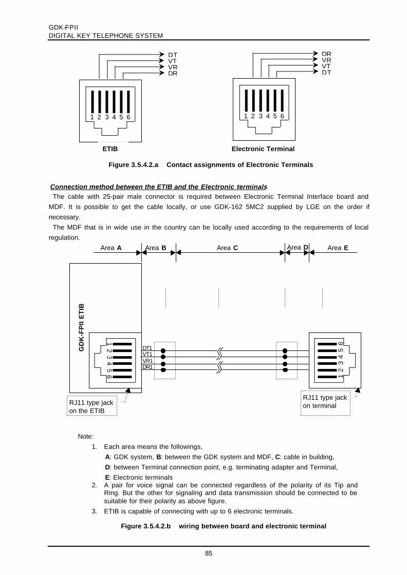
GDK-FPIIDIGITAL KEY TELEPHONE SYSTEM
85
Connection method between the ETIB and the Electronic terminalsThe cable with 25-pair male connector is required between Electronic Terminal Interface board and
MDF. It is possible to get the cable locally, or use GDK-162 5MC2 supplied by LGE on the order ifnecessary.
The MDF that is in wide use in the country can be locally used according to the requirements of localregulation.
Figure 3.5.4.2.b wiring between board and electronic terminal
Note:1. Each area means the followings,
A: GDK system, B: between the GDK system and MDF, C: cable in building,D: between Terminal connection point, e.g. terminating adapter and Terminal,E: Electronic terminals
2. A pair for voice signal can be connected regardless of the polarity of its Tip andRing. But the other for signaling and data transmission should be connected to besuitable for their polarity as above figure.
3. ETIB is capable of connecting with up to 6 electronic terminals.
Figure 3.5.4.2.a Contact assignments of Electronic Terminals
VTDT
VRDR
1 2 3 4 5 6
VRDR
VTDT
1 2 3 4 5 6
ETIB Electronic Terminal
Area A Area B Area C Area D Area E
12
34
56
GD
K-F
PII
ET
IB
RJ11 type jackon the ETIB
RJ11 type jackon terminal
VT1
65
43
21
VR1DR1
DT1

GDK-FPIIDIGITAL KEY TELEPHONE SYSTEM
86
3.5.4.3 Single line Telephone wiring
SLT interface boards such as SLIB24, SLIB48, SLIB II and DSIB are wired to SLT or standard analogdevice with a single pair of wire that provides battery feed, voice and signaling from/to the connected SLT.Typical contact assignments of RJ11 modular connector, a miniature 6-position jack as following figure3.5.4.3.a. But the contact assignments and connector type may be different from following figure inspecial countries according to the special national condition. Before wiring, it is important to check them.
The cable with 25-pair male connector is required between SLT Interface board and MDF. It is possibleto get the cable locally, or use GDK-162 5MC2 supplied by LGE on the order if necessary.
MDF can be locally used according to the requirements of local regulation and/or an usual usage in thefield.
Note:1. SLT (TE) typically operates with both polarities, since a fixed polarity is not guaranteed
according to most of specification.2. 4SLI is capable of connecting to up to 6 SLT through CN14 on MBU.
SLIB is capable of connecting to up to 12 SLT through CN16 on MBU.
MD
F
12
34
56
2550
2449
2348
2247
T1R1
T2R2
T3R3
4SLI, SLIB
Amphenol connectoron board
RJ11 socketon SLT
Figure 3.5.4.3.b wiring between board and analog TE including SLT
R
T
Figure 3.5.4.3.a contact assignments of SLT
1 2 3 4 5 6Registered Jackspecified in FCC, CFR

GDK-FPIIDIGITAL KEY TELEPHONE SYSTEM
87
3.5.4.4 Intercom/Door Phone Box installation
The Intercom/Door Phone Box is intended to be wall mounted. There are two kinds of Intercom/DoorPhone Boxes in GDK-FPII system available. KD-Digital Phone Box is can be connected to the digitalterminal interface, and KD-ICM Box is can be connected to the electronic terminal interface (ETIB). Butanother GK or GSX phone box connected to LG Analog Key Telephone System can not be connected toETIB.
At first, separate the ICM/Door Box from the base plate by inserting a flat thin edged screw driver in thebottom of the product. Press the screw driver inward which will release the retaining tan and twist thescrew driver to separate the base plate. Fasten the base plate of the ICM/Door Box to the wall with # 8screws. Route the cable through the cable entry hole in the base plate and connect the wires to the fourscrew terminals as shown in the figures 3.5.4.4.a and 3.5.4.4.b. When the wiring is complete, pull anyslack wire back through the base plate and push the housing back together.
Connection method between the Digital Interface Board and KD-Digital Phone BoxKD-Digital Phone Box can be only connected to the Digital Interface Board. Wiring from digital terminal
interface board to KD-Digital Phone Box requires one pair of wire.
Connection method between the ETIB and KD-ICM BoxKD-ICM Box can be only connected to ETIB. Wiring from electronic terminal interface board to KD-ICM
Box requires two pairs of wires.
Note: KD-Digital Phone Box operates regardless of line polarity, not with a fixed polarity
MD
F
GD
K-F
PII
DT
IB/M
BU
(DT
I)
RJ21 type connectoron the MBU
2550
2449
2348
2247
DT1DR1
DT2DR2
DT3DR3
The solderingside ofKD-DigitalPhone Box
GRRD
Figure 3.5.4.4.a wiring between the board and KD-Digital Phone Box

GDK-FPIIDIGITAL KEY TELEPHONE SYSTEM
88
Note:1. A pair for voice signal can be connected regardless of the polarity of Tip and Ring. But the other
for signaling and data transmission should be connected with a fixed polarity as above figure.2. The GSX or GK Phone Box that can be connected to the LG Analog Key Telephone System,
should not be connected to the GDK-FPII ETIB.
Figure 3.5.4.4.b wiring between the board and KD-ICM Box
The solderingside ofKD-ICM Box
GRBKYL RD
GD
K-F
PII
ET
IB
RJ11 type jackon the ETIB
VT1
65
43
21
VR1DR1
DT1

GDK-FPIIDIGITAL KEY TELEPHONE SYSTEM
89
3.5.4.5 Contact Assignments of RJ21 Type Connectors for Expansion Connector
Basically the lower most connector (CN16) is used to connect extensions with option board which isinstalled in universal slots(slot #4~7). So, any kind of extensions(digital keysets or SLTs) can beconnected to this connect. It depends on what kind of interface boards are installed.
The lower one’s detailed pin mapping is shown in Table 3.5. 4.5.
Punch-Down MBU connector CN16Block Pin Pair Pin Color-Code Designation
1 1 26 WH/BL2 1 BL/WH3 2 27 WH/OR slot #7 - R64 2 OR/WH slot #7 - T65 3 28 WH/GN slot #7 - R56 3 GN/WH slot #7 - T57 4 29 WH/BN slot #7 - R48 4 BN/WH slot #7 - T49 5 30 WH/SL slot #7 - R310 5 SL/WH slot #7 - T311 6 31 RD/BL slot #7 - R212 6 BL/RD slot #7 - T213 7 32 RD/OR slot #7 - R114 7 OR/RD slot #7 - T115 8 33 RD/GN slot #6 - R616 8 GN/RD slot #6 - T617 9 34 RD/BN slot #6 - R518 9 BN/RD slot #6 - T519 10 35 RD/SL slot #6 - R420 10 SL/RD slot #6 - T421 11 36 BK/BL slot #6 - R322 11 BL/BK slot #6 - T323 12 37 BK/OR slot #6 - R224 12 OR/BK slot #6 - T225 13 38 BK/GN slot #6 - R126 13 GN/BK slot #6 - T127 14 39 BK/BN slot #5 - R628 14 BN/BK slot #5 - T629 15 40 BK/SL slot #5 - R530 15 SL/BK slot #5 - T531 16 41 YL/BL slot #5 - R432 16 BL/YL slot #5 - T433 17 42 YL/OR slot #5 - R334 17 OR/YL slot #5 - T335 18 43 YL/GN slot #5 - R236 18 GN/YL slot #5 - T237 19 44 YL/BN slot #5 - R138 19 BN/YL slot #5 - T139 20 45 YL/SL slot #4 - R640 20 SL/YL slot #4 - T6 BL:BLUE41 21 46 VI/BL slot #4 - R5 BK:BLACK42 21 BL/VI slot #4 - T5 BN:BROWN43 22 47 VI/OR slot #4 - R4 OR:ORANGE44 22 OR/VI slot #4 - T4 WH:WHITE45 23 48 VI/GN slot #4 - R3 GN:GREEN46 23 GN/VI slot #4 - T3 SL:SLIVER47 24 49 VI/BN slot #4 - R2 VI:VIOLET48 24 BN/VI slot #4 - T2 RD:RED49 25 50 VI/SL slot #4 - R1 YL:YELLOW50 25 SL/VI slot #4 - T1
Table 3.5.4.5 EXP. Connector(CN16) Wiring

GDK-FPIIDIGITAL KEY TELEPHONE SYSTEM
90
3.5.5 PFTU Wiring
The PFTU is wired from the RJ21 type male connector on the modue itself to the MDF, cross connectedto the CO Line inputs from the telephone company, to the CO Line inputs of the system, and to PowerFailure SLTs. The CO lines and SLTs are used as CO line inputs and extensions of GDK-FPII System innormal operation, but each CO line and SLT is directly connected in power failure mode by connecting asshown in figure 3.5.5
The cable with RJ21 type female connector is required between PFTU connector and MDF. It is possibleto get the cable locally, or use GDK-162 5MC1 supplied by LGE on the order if necessary.
The MDF that is in wide use in your country can also be locally used according to the requirements oflocal regulation.
Connected to MBU(Note 3)
MD
F
126
429
SLIB1-TSLIB1-R
PFTU
2550
COT1-INCOR1-IN
227
COT1-OUTCOR1-OUT
328
TEL1-TTEL1-R
SLIB interface
CO line
LCOB interface
SLT
RJ21 type connectorin PFTU
Connected toanother PFTU
Note:1. A connector block with screws, which is connected to MBU, is supplied in the PFTU package,
but control wires are not supplied. It is recommended that 2 wires with AWG22, 24 or 26 beused for the connection of control signal.
2. The control wires can be connected regardless of their polarities .3. The control wires can be connected to CN41 on MBU with a connector block or the contact
No. 7 and 37 of CN14 on MBU without a connector block. See PFTU installation in section 2.
Figure 3.5.5 PFTU wiring

GDK-FPIIDIGITAL KEY TELEPHONE SYSTEM
91
Table 3.5.5. shows the contact assignments of RJ21 type connector on PFTU.
Punch-Down PFTU connector PFTU PFTBlock Pin Pair Pin Color-Code Designation Circuit
1 1 26 WH/BL COT1-IN 1st Circuit2 1 BL/WH COR1-IN3 2 27 WH/OR COT1-OUT4 2 OR/WH COR1-OUT5 3 28 WH/GN TEL1-T6 3 GN/WH TEL1-R7 4 29 WH/BN SLIB1-T8 4 BN/WH SLIB1-R9 5 30 WH/SL COT2-IN 2nd Circuit
10 5 SL/WH COR2-IN11 6 31 RD/BL COT2-OUT12 6 BL/RD COR2-OUT13 7 32 RD/OR TEL2-T14 7 OR/RD TEL2-R15 8 33 RD/GN SLIB2-T16 8 GN/RD SLIB2-R17 9 34 RD/BN COT3-IN 3rd Circuit18 9 BN/RD COR3-IN19 10 35 RD/SL COT3-OUT20 10 SL/RD COR3-OUT21 11 36 BK/BL TEL3-T22 11 BL/BK TEL3-R23 12 37 BK/OR SLIB3-T24 12 OR/BK SLIB3-R25 13 38 BK/GN COT4-IN 4th Circuit26 13 GN/BK COR4-IN27 14 39 BK/BN COT4-OUT28 14 BN/BK COR4-OUT29 15 40 BK/SL TEL4-T30 15 SL/BK TEL4-R31 16 41 YL/BL SLIB4-T32 16 BL/YL SLIB4-R33 17 42 YL/OR COT5-IN 5th Circuit34 17 OR/YL COR5-IN35 18 43 YL/GN COT5-OUT36 18 GN/YL COR5-OUT37 19 44 YL/BN TEL5-T38 19 BN/YL TEL5-R39 20 45 YL/SL SLIB5-T40 20 SL/YL SLIB5-R BL:BLUE
41 21 46 VI/BL COT6-IN 6th Circuit BK:BLACK42 21 BL/VI COR6-IN BN:BROWN43 22 47 VI/OR COT6-OUT OR:ORANGE44 22 OR/VI COR6-OUT WH:WHITE45 23 48 VI/GN TEL6-T GN:GREEN46 23 GN/VI TEL6-R SL: SLIVER
47 24 49 VI/BN SLIB6-T VI:VIOLET48 24 BN/VI SLIB6-R RD:RED
49 25 50 VI/SL - - YL:YELLOW50 25 SL/VI -
Table 3.5.5 PFTU Wiring

GDK-FPIIDIGITAL KEY TELEPHONE SYSTEM
92
3.5.6 Analog CO Line wiring
Analog CO boards such as 4LCO, LCOB, AC15, BWDID, TLIB are wired to the CO lines from thetelephone company through CN15, which is a RJ21 type male connector on MBU. Table 3.5.6.5 gives thecontact assignments of an RJ21 type male connector, CN15. If using the AC15 or TLIB, the contactassignments of this connector are different to normal CO lines. See AC15 wiring and TLIB wiring in thissection; sub-clauses.
The following provides details on the connection of each type of analog CO line Board.
The cable with RJ21 type female connector is required between CN15 connector and MDF. It is possibleto get the cable locally, or use GDK-162 5MC1 supplied by LGE on the order if necessary.
The MDF or terminating points that is in wide use in your country can be locally used according to therequirements of local regulation.
3.5.6.1 LCOB/4LCO wiring
4LCO, LCOB are respectively capable of connecting 4 loop start CO lines through an RJ21 type maleconnector on the MBU.
The following Figure 3.5.6.1 is an example connection in case that 4LCO is installed in slot 3. Therelation between the contact assignments of CN15 on MBU and the slots is given in Tables 3.5.6.5.
Note:1. CO lines of 4LCO/LCOB can operate regardless of line polarity.2. Connect TRC (Telecommunication reference cable) to 25th pair of RJ21 type connector if it is
supplied from Network.3. Both 4LCO/LCOB are respectively capable of connecting to up to 4 lines.
Figure 3.5.6.1 loop start CO line wiring
MD
F
126
429
R4T4
CN15 on MBU
RJ21 type connectoron the MBU
2550
R1T1
227
R2T2
328
R3T3
Network

GDK-FPIIDIGITAL KEY TELEPHONE SYSTEM
93
3.5.6.2 AC15 Board wiring -UK
AC15 is capable of connecting 2 Private lines through an RJ21 type male connector on the MBU..The following Figure 3.5.6.2 is an example connection in case that the AC15 board is installed in slot 4.
The relation between the contact assignments of CN15 on MBU and the slots is given in Tables 3.5.6.5.
MBU connector CN15(for slot #4~7)
Direct mappingto AC15 line
Remark
SLOT #N - CO1-T RX-T1
SLOT #N - CO1-R RX-R1
SLOT #N - CO2-T TX-T1 Port 1
SLOT #N - CO2-R TX-R1
SLOT #N - CO3-T RX-T2
SLOT #N - CO3-R RX-R2
SLOT #N - CO4-T TX-T2 Port 2
SLOT #N - CO4-R TX-R2
Table 3.5.6.2 Direct Mapping Table for AC15
Note:1. Above figure is an example connection in case that AC15 board is installed in slot No. 4.2. A pair of a line is for RX signal, and the other is for TX signal. So, 2 pairs of wires are
required for the connection of 1 line.3. Each pair can be connected regardless of the polarity of Tip and Ring.4. AC15 board is capable of connecting to up to 2 lines.
Figure 3.5.6.2 AC15 Private line wiring
MD
F
530
833
4R (TXR2)4T (TXT2)
CN15 on MBU
2550
1R (RXR1)1T (RXT1)
631
2R (TXR1)2T (TXT1)
732
3R (RXR2)3T (RXT2)
Network
TXRTXT
RXRRXT
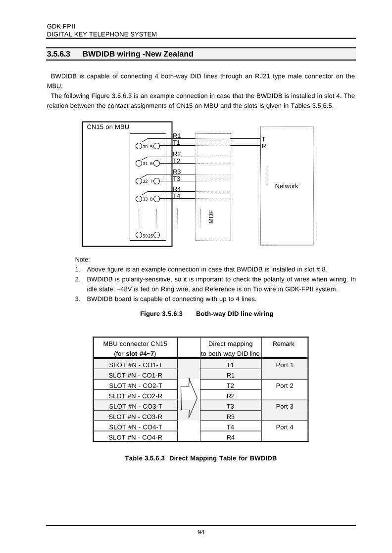
GDK-FPIIDIGITAL KEY TELEPHONE SYSTEM
94
3.5.6.3 BWDIDB wiring -New Zealand
BWDIDB is capable of connecting 4 both-way DID lines through an RJ21 type male connector on theMBU.
The following Figure 3.5.6.3 is an example connection in case that the BWDIDB is installed in slot 4. Therelation between the contact assignments of CN15 on MBU and the slots is given in Tables 3.5.6.5.
MBU connector CN15(for slot #4~7)
Direct mappingto both-way DID line
Remark
SLOT #N - CO1-T T1 Port 1
SLOT #N - CO1-R R1
SLOT #N - CO2-T T2 Port 2
SLOT #N - CO2-R R2
SLOT #N - CO3-T T3 Port 3
SLOT #N - CO3-R R3
SLOT #N - CO4-T T4 Port 4
SLOT #N - CO4-R R4
Table 3.5.6.3 Direct Mapping Table for BWDIDB
Note:1. Above figure is an example connection in case that BWDIDB is installed in slot # 8.2. BWDIDB is polarity-sensitive, so it is important to check the polarity of wires when wiring. In
idle state, –48V is fed on Ring wire, and Reference is on Tip wire in GDK-FPII system.3. BWDIDB board is capable of connecting with up to 4 lines.
Figure 3.5.6.3 Both-way DID line wiring
MD
F
530
833
R4T4
CN15 on MBU
2550
R1T1
631
R2T2
732
R3T3
Network
TR
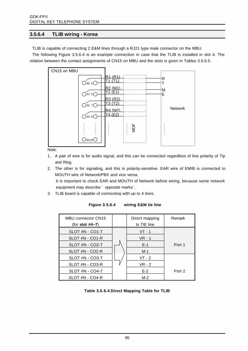
GDK-FPIIDIGITAL KEY TELEPHONE SYSTEM
95
3.5.6.4 TLIB wiring - Korea
TLIB is capable of connecting 2 E&M lines through a RJ21 type male connector on the MBU.The following Figure 3.5.6.4 is an example connection in case that the TLIB is installed in slot 4. The
relation between the contact assignments of CN15 on MBU and the slots is given in Tables 3.5.6.5.
MBU connector CN15(for slot #4~7)
Direct mappingto TIE line
Remark
SLOT #N - CO1-T VT - 1
SLOT #N - CO1-R VR - 1
SLOT #N - CO2-T E-1 Port 1
SLOT #N - CO2-R M-1
SLOT #N - CO3-T VT - 2
SLOT #N - CO3-R VR - 2
SLOT #N - CO4-T E-2 Port 2
SLOT #N - CO4-R M-2
Table 3.5.6.4 Direct Mapping Table for TLIB
Note:1. A pair of wire is for audio signal, and this can be connected regardless of line polarity of Tip
and Ring.2. The other is for signaling, and this is polarity-sensitive. EAR wire of EMIB is connected to
MOUTH wire of Network/PBX and vice versa.It is important to check EAR and MOUTH of Network before wiring, because some networkequipment may describe ‘ opposite marks ‘.
3. TLIB board is capable of connecting with up to 4 lines.
Figure 3.5.6.4 wiring E&M tie line
MD
F
530
833
R4 (M2)T4 (E2)
CN15 on MBU
2550
R1 (R1)T1 (T1)
631
R2 (M1)T2 (E1)
732
R3 (R2)T3 (T2)
Network
RT
ME

GDK-FPIIDIGITAL KEY TELEPHONE SYSTEM
96
3.5.6.5 Contact Assignments of RJ21 type Connectors on Analog CO Boards.
Table 3.5.6.5 shows the contact assignments of RJ21 type connector(CN15) on MBU.
Punch-Down MBU Connector CN15Block Pin Pair Pin Color-Code Designation
1 1 26 WH/BL CO1-R2 1 BL/WH CO1-T3 2 27 WH/OR CO2-R4 2 OR/WH CO2-T Slot #35 3 28 WH/GN CO3-R6 3 GN/WH CO3-T7 4 29 WH/BN CO4-R8 4 BN/WH CO4-T9 5 30 WH/SL CO5-R10 5 SL/WH CO5-T11 6 31 RD/BL CO6-R12 6 BL/RD CO6-T Slot #413 7 32 RD/OR CO7-R14 7 OR/RD CO7-T15 8 33 RD/GN CO8-R16 8 GN/RD CO8-T17 9 34 RD/BN CO9-R18 9 BN/RD CO9-T19 10 35 RD/SL CO10-R20 10 SL/RD CO10-T Slot #521 11 36 BK/BL CO11-R22 11 BL/BK CO11-T23 12 37 BK/OR CO12-R24 12 OR/BK CO12-T25 13 38 BK/GN CO13-R26 13 GN/BK CO13-T27 14 39 BK/BN CO14-R28 14 BN/BK CO14-T Slot #629 15 40 BK/SL CO15-R30 15 SL/BK CO15-T31 16 41 YL/BL CO16-R32 16 BL/YL CO16-T33 17 42 YL/OR CO17-R34 17 OR/YL CO17-T35 18 43 YL/GN CO18-R36 18 GN/YL CO18-T Slot #737 19 44 YL/BN CO19-R38 19 BN/YL CO19-T39 20 45 YL/SL CO20-R40 20 SL/YL CO20-T41 21 46 VI/BL - BL:BLUE42 21 BL/VI - BK:BLACK43 22 47 VI/OR - BN:BROWN44 22 OR/VI - OR:ORANGE45 23 48 VI/GN - WH:WHITE46 23 GN/VI - GN:GREEN47 24 49 VI/BN - SL:SLIVER48 24 BN/VI - VI:VIOLET49 25 50 VI/SL - RD:RED50 25 SL/VI - YL:YELLOW
Table 3.5.6.5 CO Connector (CN15) Wiring

GDK-FPII DIGITAL KEY TELEPHONE SYSTEM
97
3.5.7 ISDN wiring ISDN boards such as 2BRI, STIB and PRI contain RJ45 type jacks on each board, to connect to ISDN. Following figure shows ISND reference point and Functional group, Reference point: Theoretical point to classify the functional unit
1. V-point: PX line 2. U-point: Subscriber line
Subscriber line between public exchange and NT1 (Network termination), 2wire and 4-5Km distance
3. T-point: ISDN Trunk line Trunk line for PBX between NT1 and PBX system, 4wire and 1Km max distance.
4. S-point: ISDN standard user interface Standard point for ISDN terminal connection, physically same as T-point, multiple connection possible.
5. R-point: X or V series terminal interface. Reference point between Terminal adapter and non-ISDN terminal connection
Functional Units
1. NT1: Network Termination 2. NT2: Protocol Handle, PBX 3. TE1: Standard ISDN interface TE 4. TE2: Non-Standard ISDN interface TE 5. TA: Adapter for non-standard ISDN interface
ISDN PX
(LT)
ISDN Network
or
PC
G4-Fax
S
V,X
Terminal
SLT NT2
TA
ISDN-TEL
NT1
NT1U
UTSR
V
The position of GDK-System
Figure 3.5.7.a ISDN Reference Points and Functional Group

GDK-FPIIDIGITAL KEY TELEPHONE SYSTEM
98
ISDN trunk connection (Basic Rate)
ISDN Terminal Connection(Basic Rate)
Max. 1000 meters
GDK- FPIIISDN Board
2BRISTIB(T)
NT1 ISDNTRTR
Figure 3.5.7.b ISDN Trunk connection (Basic Rate Interface: T)
1. Point to Point connection2. TR: Termination resistor, 100 ohm
Figure 3.5.7.c ISDN Terminal connection (Basic Rate Interface: S)
1. Connection TypeP to P: Point to Point connectionP to MP: Point to Multi-Point connection
2. TR: Termination resistor, 100 ohmThis may be contained in a TE among multi-TEs.
P to P Connection TRTE TR
GD
K-S
YS
TE
M
TR
STIB(S) 2BRISTIB(T)
TRTR
Max. 1000 meters
TE1 TE2 TE8
Max. 200 meters
TRTR
TE1 TE2 TE8
Max. 500 meters
Max. 50 meters
P to MP Connection- Short Passive
P to MP Connection- Extended Passive

GDK-FPIIDIGITAL KEY TELEPHONE SYSTEM
99
ISDN Trunk connection (Primary Rate)
Physical Connectors
Basic Rate User network Interface
Primary Rate User network Interface (E1/T1)
Max. 1000 meters
GDK SystemISDN Board
PRIDSU ISDN
Figure 3.5.7.d ISDN Trunk connection (Primary Rate Interface)
1. Point to Point connection only2. Without power feed.3. Line Impedance: 120 ohm
Repeater
Table 3.5.7.a Contact assignmentsFigure 3.5.7.e RJ-45 Type Jack
1 2 3 4 5 6 7 8
ISO 8877ITU-T Rec. I.430
Contact
12345678
TE
Power Source 3Power Source 3TransmitReceiveReceiveTransmitPower Source 2Power Source 2
NT
Power Source 3Power Source 3ReceiveTransmitTransmitReceivePower Source 2Power Source 2
Polarity
+-++---+
Figure 3.5.7.f RJ-45 Type Jack
1 2 3 4 5 6 7 8
ISO 10173ANSI T1.408
Table 3.5.7.b Contact assignments
Contact
12345678
TE
ReceiveReceiveShield(R) *TransmitTransmitShield(T) *Power Source *Power Source *
NT
TransmitTransmitShield(T) *ReceiveReceiveShield(R) *Power Source *Power Source *
Polarity
-+
* Optional

GDK-FPIIDIGITAL KEY TELEPHONE SYSTEM
100
3.5.7.1 ISDN 2BRI wiring
BRIB is capable of connecting 2 Basic Rate Trunk lines through RJ45 type jacks.The contact assignments of RJ45 type jack on BRIB show in figure 3.5.7.1.a.
The TX pair of RJ45 type jack on BRIB is connected to the RX pair of NT1, and the RX one on BRIB isto the TX one of NT1 as Figure 3.5.7.1.b.
Terminating resistors should be required on each line to match line impedance. See clause 3.5.7.4.
Note:1. Connect the TX pair of an RJ45 type jack on BRIB to the RX pair of NT1 and vice versa.2. Check terminating resistors. See clause 3.5.7.4.1. 2BRI is capable of connecting to up to 2 lines.
Figure 3.5.7.1.b BRI trunk line wiring
Figure 3.5.7.1.a contact assignments of RJ-45 type jack of 2BRI board
1 2 3 4 5 6 7 8
RX+RX-TX-
TX+
NT1 (NT-Box)2BRI board
RJ45 type jack
TX+
TX-
RX+
RX-
3
6
4
5
3
6
4
5
RX+
RX-
TX+
TX-
From/to PX

GDK-FPIIDIGITAL KEY TELEPHONE SYSTEM
101
3.5.7.2 ISDN STIB wiring
STIB is capable of connecting to 2 Basic Rate Trunk lines or Terminals through RJ45 type jacks. Eachline is switchable by hardware and software setting. (see clause 3.4.6.2)
The contact assignments of RJ45 type jack on STIB show in figure 3.5.7.2.a.
The TX pair of RJ45 type jack on STIB/STIU is connected to the RX pair of NT1 or Terminal, and the RXone on STIB/STIU is to the TX one of NT1 or terminal as Figure 3.5.7.2.b.
Terminating resistors should be required on each line to match line impedance. See clause 3.5.7.4.
Figure 3.5.7.2.a contact assignments of RJ-45 Connectors of STIB
1 2 3 4 5 6 7 8
TX+TX-RX-
RX+
1 2 3 4 5 6 7 8
RX+RX-TX-
TX+
a. When a line is set to T interface a. When a line is set to S interface
Note:1. Connect the TX pair of RJ45 type jack on STIB to the RX pair of NT1 and vice versa. And connect the TX pair of RJ45 type jack on STIB to an RX pair of ISDN terminal and vice versa.2. Check terminating resistors. See clause 3.5.7.4.3. STIB is capable of connecting to up to 2 lines/terminals.
Figure 3.5.7.2.b BRI trunk line (T) or terminal connection (S) wiring
NT1 (NT-Box)STIB
RJ45 type jack
TX+
TX-
RX+
RX-
3
6
4
5
3
6
4
5
RX+
RX-
TX+
TX-
From/to PX
ISDN Terminal
RX+
RX-
TX+
TX-
3
6
4
5
3
6
4
5
TX+
TX-
RX+
RX-
S T
S T
OR
T interface
S interface

GDK-FPIIDIGITAL KEY TELEPHONE SYSTEM
102
3.5.7.3 ISDN PRI wiring
PRI board is capable of connecting to 1 Primary Rate Trunk lines through an RJ45 type jack.The contact assignments of RJ45 type jack on PRI board show in figure 3.5.7.3.a.
The TX pair of RJ45 type jack on PRI board is connected to the RX pair of DSU, and the RX one on PRIboard is to the TX one of DSU as Figure 3.5.7.3.b.
GDK-FPII PRI board is only used as TE. So the PRI board can not be used as TE even though used forQSIG function with another GDK PRIBs directly.
The contact assignments of RJ45 type jack on GDK-162/100 PRIB are not changed even though theboard is set to NT mode. See Table 3.5.7.b and Figure 3.5.7.3. So it is important that the wiring withcontact assignments of RJ45 type connector should be checked, when PRIB of another system is set tomaster mode (NT) during installation. The TX pair of RJ45 connector on PRIB in master mode isconnected to the RX pair of PRIB of another system and vice versa as following figure 3.5.7.3.c.
Note:2. Connect the TX pair of RJ45 type jack on PRI board to the RX pair of DSU and vice versa.3. PRI board is capable of connecting with 1 PRI line.
Figure 3.5.7.3.b PRI trunk line (TE connection) wiring
DSU (NT-Box)PRI board
RJ45 type jack
RX
RX
TX
TX
1
2
4
5
1
2
4
5
TX
TX
RX
RX
From/to PX
Figure 3.5.7.3.a Contact assignments of RJ-45 type jack of PRI board
1 2 3 4 5 6 7 8
RX
TXGND (T)
GND (R)
RX
TX
Note: Only two pairs of RX and TX are typically connected with RRI line.

GDK-FPIIDIGITAL KEY TELEPHONE SYSTEM
103
3.5.7.4 Terminating Resistors on Basic Rate interface(2BRI/STIB)
Terminating resistors are required on each line of BRIB/STIB for the proper operation. Switchableterminating resistors are introduced on 2BRIB issue 2 or later version and all STIB version. So thecontacts of connectors on each line of the board should be short at ON position to terminate them wheninstalling line.
Figure 3.5.7.3.c PRI line wiring with GDK system PRIBs for QSIG function
GDK-FPIIPRI (TE mode only)
GDK-162/100 PRIB/PRIU(NT mode)
RJ45 connector
RX
RX-
TX
TX
1
2
4
5
1
2
4
5
RX
RX
TX
TX
Note:1. R is 100 ohm terminating resistor, and the line is terminated at 100 ohm when switches are ON.2. Terminating connectors and shorting traps on each interface of 2BRI/STIB. See clause 3.4.5.1 and
3.4.5.2.
Figure 3.5.7.4.a Terminating method of BRIB/STIB with switchable terminating resistors
2BRI/STIB
RJ45 type jack
TX+
TX-
RX+
RX-
3
6
4
5
RX+
RX-
TX+
TX-
3
6
4
5
OR
T interface: BRIB and STIB (T)
S interface: STIB (S)
R
R
R
R
From/ToBRI Line
From/ToISDN Terminal
TE
R. R
ES
ON OFF
TE
R. R
ES
ON OFF

GDK-FPIIDIGITAL KEY TELEPHONE SYSTEM
104
But terminating resistors are not introduced on 2BRI board issue 1, which is very old version and notsupplied now. So the external terminating unit should be required to terminate if 2BRI issue1. Theexternal terminating unit can be locally got, otherwise 2923NP1656, which is the terminating unit providedby LGE, can be used.
3.5.7.5 Clock Control Cable wiring- Multi ISDN board installation
GDK-FPII system allows Multi-ISDN boards to be installed. When Multi-ISDN board installation, clockcontrol cable should be connected according to the priority of the cards. Then, in case that the ISDN lineof the board with the higher priority is in the state of Loss of signal or clock failed, the synchronized clockfor system will be supplied from next daisy chained ISDN board. Every ISDN card in TE mode generatesthe reference clock synchronized with ISDN line and transmits the clock to PLLU2 on MBU according tothe clock control signal.
High(1) state Low(0) state
IN Enable the reference clock circuit Disable the reference clock out circuit
OUT Enable next clock circuit Disable next clock circuit
Figure 3.5.7.5.a Example of multi-ISDN board installation when PRI is the highest priority.
Note:1. R is 100 ohm terminating resistors.2. 2BRI issue 1 is very old version of 2BRI. Now LGE stopped to produce 2BRI issue1.
2BRI issue 1
RJ45 type jack
TX+
TX-
RX+
RX-
3
6
4
5
T interfaceFrom/ToBRI Line
R
R
External terminating Unit
MBU
PRI(Slot No.3 only)
STIB(T interface)
STIB(T interface(s))
PLLU2
OUT IN
< <
OUT IN OUT IN
BRI LineTE
S T
PRI Line
1
Priorityof Boards
Figure 3.5.7.4.b Terminating method of BRIB/STIB without switchable terminating resistors
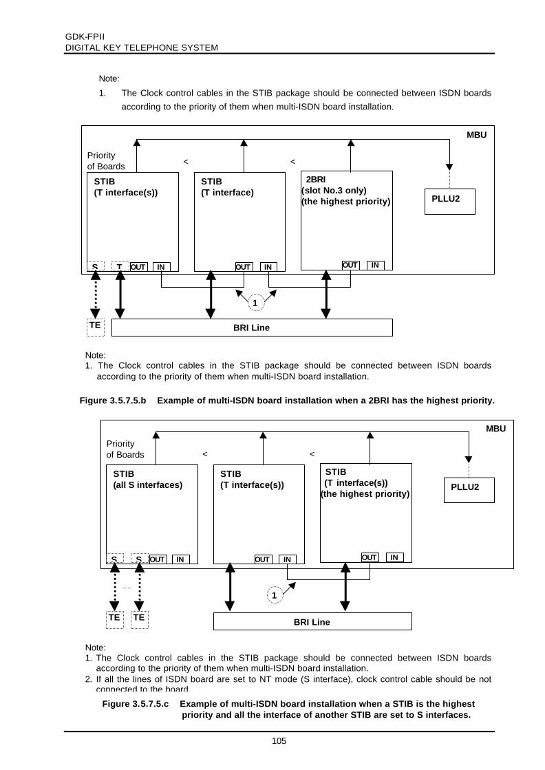
GDK-FPIIDIGITAL KEY TELEPHONE SYSTEM
105
● Note:
1. The Clock control cables in the STIB package should be connected between ISDN boardsaccording to the priority of them when multi-ISDN board installation.
Note:1. The Clock control cables in the STIB package should be connected between ISDN boards
according to the priority of them when multi-ISDN board installation.
MBU
2BRI(slot No.3 only)(the highest priority)
STIB(T interface)
STIB(T interface(s))
PLLU2
OUT IN
< <
OUT IN OUT IN
BRI LineTE
S T
1
Priorityof Boards
Figure 3.5.7.5.c Example of multi-ISDN board installation when a STIB is the highestpriority and all the interface of another STIB are set to S interfaces.
Note:1. The Clock control cables in the STIB package should be connected between ISDN boards
according to the priority of them when multi-ISDN board installation.2. If all the lines of ISDN board are set to NT mode (S interface), clock control cable should be not
connected to the board.
MBU
STIB (T interface(s))(the highest priority)
STIB(T interface(s))
STIB(all S interfaces)
OUT IN
<
OUT IN OUT IN
BRI LineTE
S
1
TE
S
<
PLLU2
Priorityof Boards
Figure 3.5.7.5.b Example of multi-ISDN board installation when a 2BRI has the highest priority.
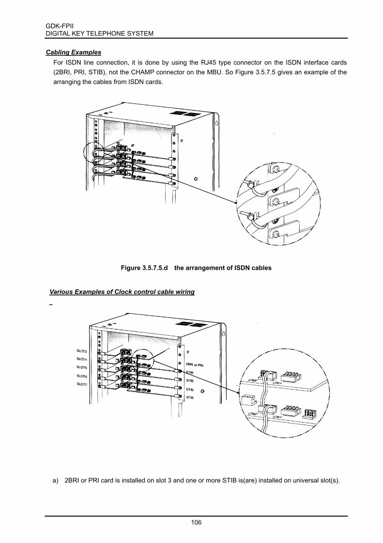
GDK-FPII DIGITAL KEY TELEPHONE SYSTEM
106
Cabling Examples For ISDN line connection, it is done by using the RJ45 type connector on the ISDN interface cards (2BRI, PRI, STIB), not the CHAMP connector on the MBU. So Figure 3.5.7.5 gives an example of the arranging the cables from ISDN cards.
Figure 3.5.7.5.d the arrangement of ISDN cables
Various Examples of Clock control cable wiring
a) 2BRI or PRI card is installed on slot 3 and one or more STIB is(are) installed on universal slot(s).

GDK-FPII DIGITAL KEY TELEPHONE SYSTEM
107
b) 2BRI or PRI card is installed on slot 3, and one or more STIB is(are) installed on slot 1 and universal slot(s).
c) STIBs are installed on universal slots.
Figure 3.5.7.5.e Clock Control Cable Wiring

GDK-FPIIDIGITAL KEY TELEPHONE SYSTEM
108
3.5.7.6 QSIG connection
GDK-FPII system supports QSIG function using ISDN boards. There are two kinds of connection forsupporting QSIG function. One is the direct connection between GDK systems with PRI line, the other isthe connection through Public Network with PRI or BRI lines.
For QSIG function, the SMEMU should be required.
Direct connection
Only GDK PRI boards can be used for the direct connection.For more details, see the manual for GDK186/100/FPII Q-signaling Interface.
The connection through Public Network
GDK-PRIB/BRIB/STIB can be used for this connection.For more details, see the manual for GDK186/100/FPII Q-signaling Interface.
Note:1. GDK-FPII PRI board could not be set to master (NT) mode.
Figure 3.5.7.6.a The direct connection for QSIG feature
GDK system GDK systemPRI (NT) PRI (TE)
Public Network
Figure 3.5.7.6.b The connection through the Public Network for QSIG feature
GDK system GDK system
Public Network
GDK system
PRI /BRI(TE)
PRI /BRI(TE) PRI /BRI(TE)

GDK-FPIIDIGITAL KEY TELEPHONE SYSTEM
109
3.5.8 Contact Assignments of various types of connectors
The contact assignments of various types of connectors are described in this clause.
3.5.8.1 RJ21 type connectors
The contact assignments of RJ21 type (25-pair Amphenol) connectors on MBU
3.5.8.2 Miniature 6-position jack
The contact assignments of miniature 6-position jack registered in FCC.
Figure 3.5.8.2 Contact assignments of miniature 6-position jack
T1R2
R1T2
1 2 3 4 5 6
Figure 3.5.8.1 Contact assignments of RJ21 type connectors
2550
126
227
328
a. Female connector b. male connector
2550
328
227
126

GDK-FPIIDIGITAL KEY TELEPHONE SYSTEM
110
3.5.8.3 Miniature 8-position jack for ISDN connection
The contact assignments of miniature 8-position jack used for ISDN connection.
a. Basic Rate User network Interface
b. Primary Rate User network Interface (E1/T1)
Figure 3.5.8.3.a RJ-45 Connector
1 2 3 4 5 6 7 8
ISO 8877ITU-T Rec. I.430
Table 3.5.8.3.a Contact assignments
Contact
12345678
TE
Power Source 3Power Source 3TransmitReceiveReceiveTransmitPower Source 2Power Source 2
NT
Power Source 3Power Source 3ReceiveTransmitTransmitReceivePower Source 2Power Source 2
Polarity
+-++---+
Figure 3.5.8.3.b RJ-45 Connector
1 2 3 4 5 6 7 8
ISO 10173ANSI T1.408 Contact
12345678
TE
ReceiveReceiveShield(R) *TransmitTransmitShield(T) *Power Source *Power Source *
NT
TransmitTransmitShield(T) *ReceiveReceiveShield(R) *Power Source *Power Source *
Polarity
-+
Table 3.5.8.3.b Contact assignments
* Optional
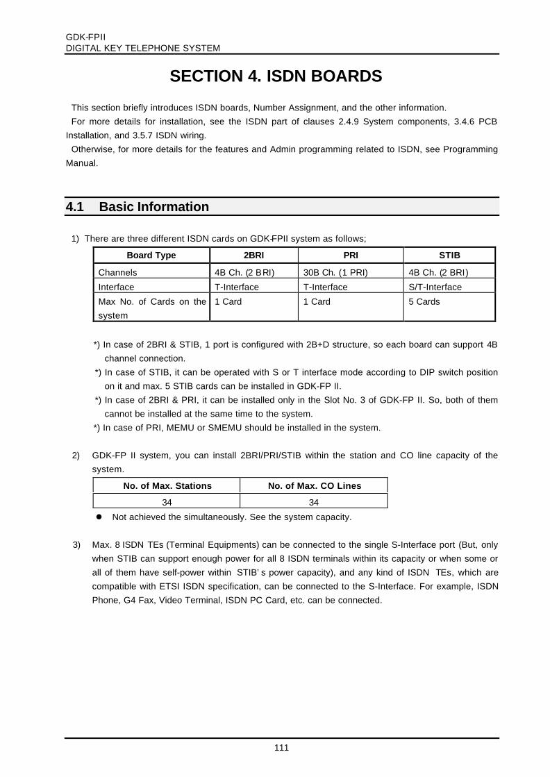
GDK-FPIIDIGITAL KEY TELEPHONE SYSTEM
111
SECTION 4. ISDN BOARDS
This section briefly introduces ISDN boards, Number Assignment, and the other information.For more details for installation, see the ISDN part of clauses 2.4.9 System components, 3.4.6 PCB
Installation, and 3.5.7 ISDN wiring.Otherwise, for more details for the features and Admin programming related to ISDN, see Programming
Manual.
4.1 Basic Information
1) There are three different ISDN cards on GDK-FPII system as follows;
Board Type 2BRI PRI STIB
Channels 4B Ch. (2 BRI) 30B Ch. (1 PRI) 4B Ch. (2 BRI)
Interface T-Interface T-Interface S/T-Interface
Max No. of Cards on thesystem
1 Card 1 Card 5 Cards
*) In case of 2BRI & STIB, 1 port is configured with 2B+D structure, so each board can support 4Bchannel connection.
*) In case of STIB, it can be operated with S or T interface mode according to DIP switch positionon it and max. 5 STIB cards can be installed in GDK-FP II.
*) In case of 2BRI & PRI, it can be installed only in the Slot No. 3 of GDK-FP II. So, both of themcannot be installed at the same time to the system.
*) In case of PRI, MEMU or SMEMU should be installed in the system. 2) GDK-FP II system, you can install 2BRI/PRI/STIB within the station and CO line capacity of the
system.
No. of Max. Stations No. of Max. CO Lines
34 34
l Not achieved the simultaneously. See the system capacity. 3) Max. 8 ISDN TEs (Terminal Equipments) can be connected to the single S-Interface port (But, only
when STIB can support enough power for all 8 ISDN terminals within its capacity or when some orall of them have self-power within STIB’s power capacity), and any kind of ISDN TEs, which arecompatible with ETSI ISDN specification, can be connected to the S-Interface. For example, ISDNPhone, G4 Fax, Video Terminal, ISDN PC Card, etc. can be connected.

GDK-FPIIDIGITAL KEY TELEPHONE SYSTEM
112
4.2 Station/CO Line Number Assignments (1) As same as any other station/CO cards, the station/CO line number on ISDN card is assigned by
PGM 02 in Admin. Programming. (2) In PRI board, the 30 continuous CO line numbers are assigned by PGM 02. (3) In 2BRI board, the 4 continuous CO line numbers are assigned by PGM 02. Two continuous CO
line numbers are assigned per each port (2B+D). (4) In STIB with all T-Interface, as same as 2BRI, the 4 continuous CO line numbers are assigned by
PGM 02. Two continuous CO line numbers are assigned per each port (2B+D). (5) In STIB with all S-Interface, the 4 continuous station numbers are assigned by PGM 02. Two
continuous station numbers are assigned per each port (2B+D). (6) If STIB is used for S-Interface and T-interface, then system assigns the continuous CO line No. on
each T-Interface, and the continuous station No. on each S-Interface as follows;
(If the first Sta. No. is 120 and the first CO No. is 24 )
Port 1 S-Interface Station 120~121STIB BoardPort 2 T-Interface CO Line 24 ~25
(7) Two continuous station numbers assigned to a single S-Interface act as the same station No. Forexample, calling to station 120 is the same as calling to station 121.
(8) If you want to change S-Interface to T-Interface, or vise versa, on STIB board, you have to re-
program Slot Assignment (PGM 02) even if the slot assignment is not changed and reset the GDKsystem. After that, system works as required.
(9) In STIB,To use 'T' interface only - Slot Assignment (PGM 02) at COL onlyTo use 'T' & 'S' interface - Slot Assignment (PGM 02) at COL & STATo use 'S' interface only - Slot Assignment (PGM 02) at COL & STA
4.3 Other Information
l ISDN TEs (Terminal Equipment)
(1) There are many ISDN TEs(ex. ISDN Phone, Video-Phone, G4 Fax, PC-Card, etc.). The GDK-FP II supports all ISDN TEs, which are compatible with Euro-ISDN (ETSI ISDN Specification)till now on.
(2) ISDN phone can call another station (DKTU,EKTU,SLT) connected to the GDK-FPII and
access analog/ISDN CO lines. (3) The LCD display on ISDN TE is depending on its own feature, not GDK-FP II system’s feature.
1) Etc.o ISDN station cannot be the master of conference and a member of conference.o ISDN station cannot call station which is activated to Off-net Call Forward.o ISDN station cannot be an attendant station.o ISDN station cannot belong to Hunt Group.

GDK-FPIIDIGITAL KEY TELEPHONE SYSTEM
113
SECTION 5. CUSTOMER DATABASE PROGRAMMING
5.1 INTRODUCTION
The GDK Key Telephone System can be programmed to meet each customer's individual need. Allprogramming is done at station 100 (station port # 00) using KD-36D digital key telephone. (You cannotprogram with Large LCD keyset.). Additional programming stations can be assigned (PGM 21-BTN 4),but only 1 keyset can be active in programming mode at any one time. (While activating GDK PC Admin,no keyset can be active and the reverse also.)
Upon entering the program mode, the key telephone at station 100 cannot operate as a normaltelephone but as a programming instrument with all of the buttons redefined. The keys of the dial pad areused to enter the various data fields and to enter numerical information. The 24 buttons located at the topof the phone (Flexible Buttons) are used to indicate the specific data field and to enter information.Sometimes the [SPEED] button and ‘*’ of the dial pad is used to delete the data or to indicate end of datainput.
See TABLE 5.6.1 - 5.6.20 for default data. If this pre-programming suits the customer, additional adminprogram is not necessary. To change admin data, the user enters the admin. programming mode andselect program code. During admin programming other keysets operate normally.
When Admin programming, LCD and LEDs indicate the current programmed data and status. If theprogrammer enters correct data, then LCD and LEDs show the entered data and the data is stored in thetemporary buffer area. Real system databases is not changed and has no effect on telephone operationunless permanent-updating procedure is executed. Pressing [HOLD/SAVE] button, all data in thetemporary buffer (same as LCD and LEDs show their status) is saved into permanent memory. Tones areprovided to let the programmer know data entry is correct (confirmation tone) or not (error tone).
5.2 TO ENTER THE PROGRAMMING MODE
1. Lift handset or press the [MON] button on the admin station, and hear ICM dial tone (optional).
2. Press the [TRANS/PGM] button and dial *# (Confirmation tone is heard).
3. Enter Admin password if the password has been set. This places the station into the adminprogramming mode (confirmation tone heard).
Each program is accessed by pressing the [TRANS/PGM] button and dialing the two-digit programnumber. If an error is made while entering data, the [s] or the [TRANS/PGM] button can go the previousstatus. When the [TRANS/PGM] button is pressed, the LCD will display;
ENTER PROGRAM CODE

GDK-FPIIDIGITAL KEY TELEPHONE SYSTEM
114
5.3 PERMANENT UPDATE PROCEDURE
When the data has been entered, the [HOLD/SAVE] button is used to store the data permanently. If alldata was entered correctly, confirmation tone is heard when pressing the [HOLD/SAVE] button. If therewere any errors in the entry, then an error tone is presented and data is not stored in the permanentmemory.
5.4 NUMBERING PLAN
The following numbering plan can be changed by Admin Programming 01 depending on the user'sneeds.
NUMBER ITEM REMARK
162 100–291
100 100–235
FPII 100–177
Station Number
162 620–649
100 620–634
FPII 620-627
Station Group Number
3 PGM Enter Code SLT
162 401-420
100 401-415
FPII 401-405
Internal Page Zones
43 Internal All Call Paging
44 Meet Me Page
46 External Page Zone -1
47 External Page Zone -2
48 External All Call Paging
49 All Call Paging
50 Enter SMDR Account Code 4/8 BTN Keyset, SLT
51 Flash Command to CO Line
52 Last Number Redial (LNR)
53 Do Not Disturb
54 Call Forward
55 Station Speed Dial
56 Message Wait Enable
57 Message Wait Answer
58 Speed Dial Access
59 Cancel DND/Call Forward/Pre-selected MSG
162 601-619
100 601-610
FPII 601-605
Call Park Location
65 Alarm Reset
66 Group Call Pick-up

GDK-FPIIDIGITAL KEY TELEPHONE SYSTEM
115
NUMBER ITEM REMARK
67# DVU – Record User Greeting for Busy Forwarding
67* DVU – Delete User Greeting for Busy Forwarding
670 DVU – Play User Greeting for Busy Forwarding
671 DVU – Time Announcement
672 DVU – Date Announcement
673 DVU – Station Number Announcement
674 DVU – Record User Greeting for No Answer Forwarding
675 DVU – Delete User Greeting for No Answer Forwarding
676 DVU – Play User Greeting for No Answer Forwarding
677 DVU – Station Statue Announcement
678 DVU – Record Page Announcement
679 DVU – Retrieve Page Announcement
69 Universal Night Answer (UNA)
7XXX Direct Call Pick-up (XXX = Station Number)
162 801-848
100 801-824
FPII 801-809
CO Group Access
162 8801-8896
100 8801-8848
FPII 8801-8834
CO Line Access
89 Tie Routing Access
8## Retrieve Holding CO Group Keyset
162 8#01-8#96
100 8#01-8#48
FPII 8#01-8#34
Retrieve Holding CO Line Keyset
9 Access the first CO line
0 Attendant Call
*0 Print SMDR (Station Base) Attendant
*1 Print SMDR (Account Group Base) Attendant
*2 Delete SMDR (Station Base) Attendant
*3 Delete SMDR (Account Group Base) Attendant
*4 Display Call Charge on LCD Attendant
** Abort SMDR Printing Attendant
#*1 Door Open 1
#*2 Door Open 2
#*3 Door Open 3
#*4 Door Open 4
*8 VM Message Wait Enable
*9 VM Message Wait Cancel
[SPEED] + * Last Number Redial
[SPEED] + # Save Number Redial Keyset
[SPEED] + 00-19 Station Speed Dial Access Keyset
[SPEED] + XXX
System Speed Dial Access XXX (Bin No. of SystemSpeed Dial)
162: 200-999
100/FPII: 200-399

GDK-FPIIDIGITAL KEY TELEPHONE SYSTEM
116
n To enter user programming mode, press the [TRANS/PGM] button in a keyset or dial 3
(Programming enter code) in a SLT.
n The following numbering plan is fixed, cannot be changed by Admin. Programming.
NUMBER ITEM REMARK
18 Walking COS Keyset
30 Station User Name Registration 4/8 BTN Keyset, SLT
25 Receive Station Number from KSU WHTU only
29 Erase Subscription Data ATD only
2* Display Date / Time WHTU only
40 MPB Version Display Keyset
41# Wake-up Time Registration (Continuous )
41 Wake-up Time Registration (One-time)
42 Wake-up Time Cancel
43 SMEMU Serial Number Display Keyset with LCD
44 Authorization Code Registration
45 Authorization Code Change
46 Station COS Change
47 Station COS Restore
48 Custom Message Display (Message 00)
49 Intercom Answer Mode (1 HF / 2 TONE / 3 PV) Digital Keyset
50 Differential Ring
51 LCD Display Mode (English/Korean) Keyset
52 Set World Time “
54 [RECORD] BTN Assignment – With Voice Mail Keyset
55 Restrict DID Ring System Attendant
56 Restore DID Ring System Attendant
57 Headset/Speakerphone Mode Keyset
58 [COLR] BTN Assignment “
59 Erase All CO Message Wait “
61 Enable/Disable DID Call Wait “
62 Enable/Disable Send Keypad Facility IE “
73 Background Music "
77XX Custom Message Display (XX = 00-20) "
80 [Dial Memo] BTN Assignment "
81 [Account Code] BTN Assignment "
83 [ICM Hold] BTN Assignment "
84 [LOOP] BTN Assignment "
85 [Camp-on] BTN Assignment "
86 [ATD Override] BTN Assignment "
87 [UCD DND] BTN Assignment "
88 [ACNR] BTN Assignment "
89 [Stop Watch] BTN Assignment "
8* [ACD] BTN Assignment Digital Keyset
8# [Data Module] BTN Assignment Digital Keyset

GDK-FPIIDIGITAL KEY TELEPHONE SYSTEM
117
NUMBER ITEM REMARK
90 [SPEED] BTN Assignment 4/8 BTN Keyset
91 [CONF] BTN Assignment "
92 [CALLBK] BTN Assignment "
93 [DND/FWD] BTN Assignment "
94 [FLASH] BTN Assignment "
95 [MUTE] BTN Assignment "
96 [MON] BTN Assignment "
97 [CLIR] BTN Assignment Keyset
41# Wake-up Time Registration (Continuous ) Attendant
41 Wake-up Time Registration (One-time) "
42 Wake-up Time Cancel "
*4 Authorization Code Cancel System Attendant
*5 LCD Date Mode Change "
*6 LCD Time Mode Change "
*7 Custom Display Message Program (11-20) "
*8 CO Line Access Attendant
*9 DND/Call Forward/Pre-selected MSG Cancel "
*0 Door Phone Music Selection "
#1 System Date/Time Setting "
#2 Station COS Change (COS 7) "
#3 Station COS Restore "
#4 DVU - Record System Greeting System Attendant
#5 External Page Music -1 Assignment/Cancel Attendant
#6 External Page Music -2 Assignment/Cancel Attendant
#71 Start Traffic Analysis System Attendant
#72 Disable Traffic Analysis "
#73 Print Traffic Analysis "
#74 Abort Traffic Analysis "
#8 Dial By Name "
#9 Automatic Day/Night Mode Program Attendant
## Subscribe WHTU ATD only
*# Admin Programming Code

GDK-FPIIDIGITAL KEY TELEPHONE SYSTEM
118
5.5 ADMIN PROGRAMMING INDEX
INITIALIZATION PGM 00 Database Initialization
FLEXIBLE NUMBERING PLAN PGM 01 Flexible Numbering Plan
SLOT ASSIGNMENT PGM 02 Slot Assignment
MSN/SUB ADDRESS ASSIGNMENT PGM 03
PGM 03
PGM 04
MSN/Sub-address Assignment (GDK-162)
PTRP Gain Table Program (GDK-100/FPII)
PTRP Gain Table Program (GDK-162)
FLEXIBLE DID TABLE PGM 05 Flexible DID Table
EMERGENCY SERVICE CALL TABLE PGM 06 Emergency Call
LCR(LEAST COST ROUTING) PGM 07 LCR
SYSTEM ATTRIBUTE – IV PGM 08 System Attribute - IV
ISDN COLP TABLE PGM 09 ISDN COLP TABLE
STATION BASE PROGRAM PGM 10 Station Attribute - I
PGM 11 Station Attribute - II
PGM 12 Station Attribute - III
PGM 13 Station ID Assignment
PGM 14 Station Class-Of-Service
PGM 15 CO Line Group Access
PGM 16 ICM Tenancy Group
PGM 17 Internal Page Zone
PGM 18 Preset Call Forward
PGM 19 Hot Line/Warm Line
PGM 20 SMDR Account Group
PGM 21 Station Attribute - IV
PGM 22 CTI Attribute
PGM 23 ISDN Station Attributes - V
PGM 24 Station Attribute - VI
PGM 28 Linked Pairs
PGM 29 Flex Buttons Assignment
CO LINE BASE PROGRAM PGM 30 CO Line Attribute – I
PGM 31 CO Line Attribute - II
PGM 32 CO Line Ring Assignment
PGM 33 CO Flash Timer
PGM 34 Open Loop Detect Timer
PGM 35 TIE Line Assignment
PGM 36 DID Line Assignment
PGM 37 CO Line Attribute – III
PGM 38 CO Line Attribute – IV
PGM 39 R2 DCOB CO Line Attribute
SYSTEM BASE PROGRAM PGM 40 System Attribute - I
PGM 41 System Attribute - II
PGM 42 System Attribute - III
PGM 43 System Timer - I
PGM 44 System Timer - II
PGM 45 Admin Password

GDK-FPIIDIGITAL KEY TELEPHONE SYSTEM
119
SYSTEM BASE PROGRAM PGM 46 Main Attendant Assignment
PGM 47 Station GroupPGM 48 Station Group Attribute
PGM 49 Executive/Secretary Pairs
PGM 50 Alarm AttributePGM 51 External Control Contact
PGM 52 PBX Access Code
PGM 53 SMDR Long Distance CodesPGM 54 Authorization Code
PGM 55 DID Digit Conversion
PGM 56 DID/DISA DestinationPGM 57 Pulse Dial Speed Ratio
PGM 58 Modem Assignment
PGM 59 Setting System Date/TimePGM 60 LCD Date/Time Display Mode
PGM 61 S/W Version Display
PGM 62 SMDR Attribute - IPGM 63 SMDR Attribute - II
PGM 65 TIE Routing Tables
PGM 66 System Gain ControlPGM 67 System Speed Zone Programming
PGM 68 ACNR Tone Cadence
PGM 69 System Tone FrequencyPGM 71 World Time Attribute
PGM 72 Display World Time
PGM 73 Voice Mail Dialing CodesPGM 74 CO Line Name Assignment
PGM 75 Ring Frequency (Called Station base)
PGM 76 Ring Frequency (Calling Station base)PGM 77 DCO TX Gain Control
PGM 78 Digit Insert Table
PGM 79 CCR TablePGM 92 Nation Specific Attribute - I (For Australia)
PGM #1 System Attributes - V
TOLL TABLE PGM 70 Exception TablePGM 64 Canned Toll Exception Table
PRINT DATABASE PGM 80 Database Print
HOTEL PROGRAMMING(See Hotel Programming Manual for detail)
PGM 81PGM 82
PGM 83
PGM 84PGM 85
PGM 86
PGM 87PGM 88
PGM 89
Hotel Attribute SettingHotel Room Attribute
Hotel Service Station
Class of RoomRoom Rate Attribute
Attribute of Call Charge Rate
Bar Product NamesTax Rate
Fee for Part Time
QSIG TABLE PGM *1 QSIG Basic AttributePGM *2 QSIG Routing Table

GDK-FPIIDIGITAL KEY TELEPHONE SYSTEM
120
5.6 DEFAULT VALUES※ The default values may be different by country adaptation.
TABLE 5.6.1 INITIALIZATION
PGM BTN ITEM DEFAULT REMARK
00 1 Station Data Initialization -
2 CO Line Data Initialization -
3 System Data Initialization -
4 Flex. Buttons Data Initialization -
5 Toll Table Initialization -
6 Flexible Numbering Plan Initialization -
7 Slot Assignment Initialization -
8 All Data Initialization -
9 Nation / Extend Initialization KOREA/BASIC
10 System S/W Reset -
TABLE 5.6.2 FLEXIBLE NUMBERING PLAN – GDK-162
PGM BTN ITEM BASIC EXTEND REMARK
01 First 24 Flexible Number
1 Station Number 100-291 100-699
2 Station Group Number 620-649 *620-*649
3 Station PGM Enter Code 3 *3 SLT
4 Internal Page Zones 401-420 *401-*420
5 Internal All Call Page 43 *43
6 Meet Me Page 44 *44
7 External Page Zone - 1 46 *46
8 External Page Zone - 2 47 *47
9 External All Call Page 48 *48
10 All Call Page (EXT/INT) 49 *49
11 Enter SMDR Account Code 50 *50
12 Flash Command to CO line 51 *51
13 Last Number Redial (LNR) 52 *52
14 Do-Not-Disturb 53 *53
15 Call Forward 54 *54
16 Speed Dial Programming 55 *55
17 MSG Wait/Call-Back Enable 56 *56
18 MSG Wait/Call-Back Answer 57 *57
19 Speed Dial Access 58 *58
20 Cancel DND/CFW/ Pre-selected MSG
59 *59
21 Call Park Locations 601- 619 *601-*619
22 Alarm Reset 65 *65
23 Group Call Pick-Up 66 *66
24 Station DVU Access 67 *67
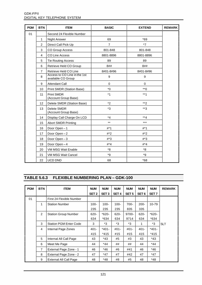
GDK-FPIIDIGITAL KEY TELEPHONE SYSTEM
121
PGM BTN ITEM BASIC EXTEND REMARK
01 Second 24 Flexible Number
1 Night Answer 69 *69
2 Direct Call Pick-Up 7 *7
3 CO Group Access 801-848 801-848
4 CO Line Access 8801-8896 8801-8896
5 Tie Routing Access 89 89
6 Retrieve Held CO Group 8## 8##
7 Retrieve Held CO Line 8#01-8#96 8#01-8#96
8 Access to CO Line in the 1stavailable CO Group 9 9
9 Attendant Call 0 0
10 Print SMDR (Station Base) *0 **0
11 Print SMDR(Account Group Base)
*1 **1
12 Delete SMDR (Station Base) *2 **2
13 Delete SMDR(Account Group Base)
*3 **3
14 Display Call Charge On LCD *4 **4
15 Abort SMDR Printing ** ***
16 Door Open – 1 #*1 #*1
17 Door Open – 2 #*2 #*2
18 Door Open – 3 #*3 #*3
19 Door Open – 4 #*4 #*4
20 VM MSG Wait Enable *8 *8
21 VM MSG Wait Cancel *9 *9
22 UCD DND 68 *68
TABLE 5.6.3 FLEXIBLE NUMBERING PLAN – GDK-100
PGM BTN ITEM NUM
SET 2
NUM
SET 3
NUM
SET 4
NUM
SET 5
NUM
SET 6
NUM
SET 7
REMARK
01 First 24 Flexible Number
1 Station Number 100-
235
100-
235
100-
235
700-
835
200-
335
10-79
2 Station Group Number 620-634
*620-*634
620-634
9700-9714
620-634
*620-*634
3 Station PGM Enter Code 3 *3 *3 *3 1 *3 SLT
4 Internal Page Zones 401-
415
*401-
*415
#01-
#15
#01-
#15
401-
415
*401-
*415
5 Internal All Call Page 43 *43 #5 #3 43 *43
6 Meet Me Page 44 *44 ## ## 44 *44
7 External Page Zone - 1 46 *46 #6 #41 46 *46
8 External Page Zone - 2 47 *47 #7 #42 47 *47
9 External All Call Page 48 *48 #8 #5 48 *48

GDK-FPIIDIGITAL KEY TELEPHONE SYSTEM
122
PGM BTN ITEM NUM
SET 2
NUM
SET 3
NUM
SET 4
NUM
SET 5
NUM
SET 6
NUM
SET 7
REMARK
10 All Call Page (EXT/INT) 49 *49 #00 #6 49 *49
11 Enter SMDR Account Code 50 *50 50 91 50 *50
12 Flash Command to CO line 51 *51 51 51 51 *51
13 Last Number Redial (LNR) 52 *52 52 52 52 *52
14 Do-Not-Disturb 53 *53 53 53 53 *53
15 Call Forward 54 *54 54 49 54 *54
16 Speed Dial Programming 55 *55 55 *40 55 *55
17 MSG Wait/Call-Back Enable 56 *56 56 *66 56 *56
18 MSG Wait/Call-Back Answer 57 *57 57 *67 57 *57
19 Speed Dial Access 58 *58 58 *9 58 *58
20 Cancel DND/CFW/ Pre-selected MSG
59 *59 59 59 59 *59
21 Call Park Locations 601-
610
*601-
*610
601-
610
950-
959
601-
610
*601-
*610
22 Alarm Reset 65 *65 65 *65 65 *65
23 Group Call Pick-Up 66 *66 ** *1 66 *66
24 Station DVU Access 67 *67 40 *22 67 *67
01 Second 24 Flexible Number
1 Night Answer 69 *69 77 2 69 *69
2 Direct Call Pick-Up 7 *7 *7 *42 7 *7
3 CO Group Access 801-
824
801-
824
801-
824
401-
424
801-
824
801-
824
SLT
4 CO Line Access 8801-8848
8801-8848
8801-8848
4801-4848
8801-8848
8801-8848
5 Tie Routing Access 89 89 89 47 89 89
6 Retrieve Held CO Group 8## 8## 8## 4* 8## 8##
7 Retrieve Held CO Line 8#01-
8#48
8#01-
8#48
8#01-
8#48
4#01-
4#48
8#01-
8#48
8#01-
8#48
8 Access to CO Line in the 1stavailable CO Group
9 9 9 1 0 9
9 Attendant Call 0 0 0 0 9 0
10 Print SMDR (Station Base) *0 **0 661 671 *0 **0
11 Print SMDR(Account Group Base)
*1 **1 662 672 *1 **1
12 Delete SMDR (Station Base) *2 **2 663 673 *2 **2
13 Delete SMDR(Account Group Base)
*3 **3 664 674 *3 **3
14 Display Call Charge On LCD *4 **4 665 **4 *4 **4
15 Abort SMDR Printing ** *** 666 *** ** ***
16 Door Open – 1 #*1 #*1 #*1 #*1 #*1 #*1
17 Door Open – 2 #*2 #*2 #*2 #*2 #*2 #*2
18 Door Open – 3 #*3 #*3 #*3 #*3 #*3 #*3
19 Door Open – 4 #*4 #*4 #*4 #*4 #*4 #*4
20 VM MSG Wait Enable *8 *8 *8 *8 *8 *8
21 VM MSG Wait Cancel *9 *9 *9 **9 *9 *9
22 UCD DND 68 *68 68 68 68 *68

GDK-FPIIDIGITAL KEY TELEPHONE SYSTEM
123
TABLE 5.6.4 FLEXIBLE NUMBERING PLAN – GDK-FPII
PGM BTN ITEM NUM
SET 2
NUM
SET 3
NUM
SET 4
NUM
SET 5
NUM
SET 6
NUM
SET 7
REMARK
01 First 24 Flexible Number
1 Station Number 100-
177
100-
177
100-
177
700-
777
200-
277
10-79
2 Station Group Number 620-
627
*620-
*627
620-
627
9700-
9707
620-
627
*620-
*627
3 Station PGM Enter Code 3 *3 *3 *3 1 *3 SLT
4 Internal Page Zones 401-
405
*401-
*405
#01-
#05
#01-
#05
401-
405
*401-
*405
5 Internal All Call Page 43 *43 #5 #3 43 *43
6 Meet Me Page 44 *44 ## ## 44 *44
7 External Page Zone - 1 46 *46 #6 #41 46 *46
8 External Page Zone - 2
9 External All Call Page 48 *48 #8 #5 48 *48
10 All Call Page (EXT/INT) 49 *49 #00 #6 49 *49
11 Enter SMDR Account Code 50 *50 50 91 50 *50
12 Flash Command to CO line 51 *51 51 51 51 *51
13 Last Number Redial (LNR) 52 *52 52 52 52 *52
14 Do-Not-Disturb 53 *53 53 53 53 *53
15 Call Forward 54 *54 54 49 54 *54
16 Speed Dial Programming 55 *55 55 *40 55 *55
17 MSG Wait/Call-Back Enable 56 *56 56 *66 56 *56
18 MSG Wait/Call-Back Answer 57 *57 57 *67 57 *57
19 Speed Dial Access 58 *58 58 *9 58 *58
20 Cancel DND/CFW
/ Pre-selected MSG
59 *59 59 59 59 *59
21 Call Park Locations 601-
605
*601-
*605
601-
605
950-
954
601-
605
*601-
*605
22 Alarm Reset 65 *65 65 *65 65 *65
23 Group Call Pick-Up 66 *66 ** *1 66 *66
24 Station DVU Access 67 *67 40 *22 67 *67
01 Second 24 Flexible Number
1 Night Answer 69 *69 77 2 69 *69
2 Direct Call Pick-Up 7 *7 *7 *42 7 *7
3 CO Group Access 801-
809
801-
809
801-
809
401-
409
801-
809
801-
809
SLT
4 CO Line Access 8801-
8834
8801-
8834
8801-
8834
4801-
4834
8801-
8834
8801-
8834
5 Tie Routing Access 89 89 89 47 89 89
6 Retrieve Held CO Group 8## 8## 8## 4* 8## 8##
7 Retrieve Held CO Line 8#01-
8#34
8#01-
8#34
8#01-
8#34
4#01-
4#34
8#01-
8#34
8#01-
8#34

GDK-FPIIDIGITAL KEY TELEPHONE SYSTEM
124
PGM BTN ITEM NUM
SET 2
NUM
SET 3
NUM
SET 4
NUM
SET 5
NUM
SET 6
NUM
SET 7
REMARK
8 Access to CO Line in the 1st
available CO Group
9 9 9 1 0 9
9 Attendant Call 0 0 0 0 9 0
10 Print SMDR (Station Base) *0 **0 661 671 *0 **0
11 Print SMDR
(Account Group Base)
*1 **1 662 672 *1 **1
12 Delete SMDR (Station Base) *2 **2 663 673 *2 **2
13 Delete SMDR
(Account Group Base)
*3 **3 664 674 *3 **3
14 Display Call Charge On LCD *4 **4 665 **4 *4 **4
15 Abort SMDR Printing ** *** 666 *** ** ***
16 Door Open – 1 #*1 #*1 #*1 #*1 #*1 #*1
17 Door Open – 2 #*2 #*2 #*2 #*2 #*2 #*2
18 Door Open – 3
19 Door Open – 4
20 VM MSG Wait Enable *8 *8 *8 *8 *8 *8
21 VM MSG Wait Cancel *9 *9 *9 **9 *9 *9
22 UCD DND 68 *68 68 68 68 *68
TABLE 5.6.5 SLOT ASSIGNMENT
PGM SYS BTN DEFAULT REMARK
02 GDK-FP II 1 03 CO Line Slot Assignment
Max. 34 CO lines or Max. 6 slots
2 02 Station Slot Assignment
Max. 78 stations or Max. 7 slots
3 08 WTIB Port Number
4 30 No. of Basic Primary Dev. (PRIB, DCOB, R2)
GDK-100 1 08 07 06 12 11 CO Line Slot Assignment
Max. 48 CO lines or Max. 8 slots
2 01 02 03 04 05 09 10 11 Station Slot Assignment
Max. 136 stations
3 08 WTIB Port Number
4 30 No. of Basic Primary Dev. (PRIB, DCOB, R2)
GDK-162 1 06 07 08 14 15 16 17 CO Line Slot Assignment
Max. 96 CO lines
2 02 03 04 05 09 10 11 12 13 Station Slot Assignment
Max. 186 stations
3 08 WTIB Port Number
4 30 No. of Basic Primary Dev. (PRIB, DCOB, R2)
5 30 No. of Option Primary Dev. (PRIU)
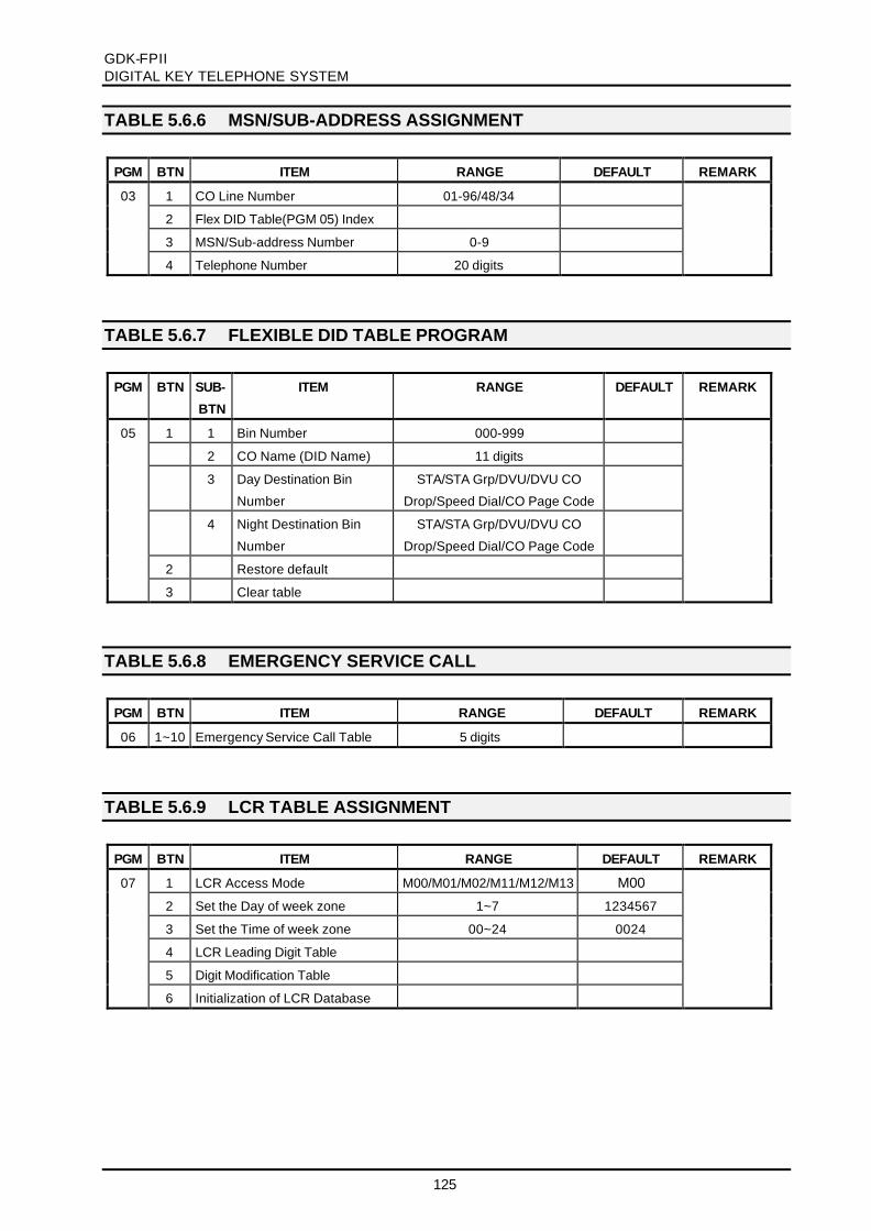
GDK-FPIIDIGITAL KEY TELEPHONE SYSTEM
125
TABLE 5.6.6 MSN/SUB-ADDRESS ASSIGNMENT
PGM BTN ITEM RANGE DEFAULT REMARK
03 1 CO Line Number 01-96/48/34
2 Flex DID Table(PGM 05) Index
3 MSN/Sub-address Number 0-9
4 Telephone Number 20 digits
TABLE 5.6.7 FLEXIBLE DID TABLE PROGRAM
PGM BTN SUB-
BTN
ITEM RANGE DEFAULT REMARK
05 1 1 Bin Number 000-999
2 CO Name (DID Name) 11 digits
3 Day Destination Bin
Number
STA/STA Grp/DVU/DVU CO
Drop/Speed Dial/CO Page Code
4 Night Destination Bin
Number
STA/STA Grp/DVU/DVU CO
Drop/Speed Dial/CO Page Code
2 Restore default
3 Clear table
TABLE 5.6.8 EMERGENCY SERVICE CALL
PGM BTN ITEM RANGE DEFAULT REMARK
06 1~10 Emergency Service Call Table 5 digits
TABLE 5.6.9 LCR TABLE ASSIGNMENT
PGM BTN ITEM RANGE DEFAULT REMARK
07 1 LCR Access Mode M00/M01/M02/M11/M12/M13 M00
2 Set the Day of week zone 1~7 1234567
3 Set the Time of week zone 00~24 0024
4 LCR Leading Digit Table
5 Digit Modification Table
6 Initialization of LCR Database

GDK-FPIIDIGITAL KEY TELEPHONE SYSTEM
126
TABLE 5.6.10 SYSTEM ATTRIBUTE - IV
PGM BTN ITEM RANGE DEFAULT REMARK
08 1 In Prefix Code Insertion 1/0 0 (OFF)
2 My area code 5 digits
3 CO ATD Code 2 digits
4 DID Conversion Table 0/1/2 0
5 Calling Sub Address 1/0 0 (OFF)
6 Type of Calling Number 0~4 2 (National No.)
7 Advice of Charge 0~5 0
8 Out Prefix Code Insertion 1/0 1 (ON)
9 Paging Conference Index Internal Page Group
10 U-A Law Line Installed 1/0 0 (OFF)
11 ISDN Sending Mode 1/0 0 (Overlap)
12 Enblock Inter-digit Timer 15
For Israel
For Israel
13 Prefix Code 2 digits 0
14 International Access Code 4 digits
15 LCR Display/Print Mode 0/1 1
TABLE 5.6.11 ISDN COLP TABLE ASSIGNMENT
PGM BTN ITEM RANGE DEFAULT REMARK
09 1-10 ISDN COLP Table 10 digits
TABLE 5.6.12 STATION BASE PROGRAM
PGM BTN ITEM DEFAULT REMARKRANGE
FP II 100 162
10 1 DND (Do-Not-Disturb) YES / NO NO
2 Speed Dial Access YES / NO YES
3 Page Access YES / NO NO
4 Call Forward Access YES / NO NO
5 PLA (Preferred Line Answer) YES / NO YES
6 Auto Speaker Select YES / NO YES
7 Warm Line YES / NO NO
8 SMDR Dial Digit Hidden Display YES / NO NO
11 1 CO Line Queuing YES / NO YES
2 3-Minute Warning Tone YES / NO NO
3 Override Privilege YES / NO NO
4 Automatic CO Hold
YES-For Attendant, NO-For Others
YES / NO
5 Data Line Security YES / NO NO
6 Group Listening YES / NO NO
7 Speaker-Phone/Headset SP / HEAD Speakerphone
8 Howling Tone To SLT YES / NO YES
9 DID Call Waiting on busy station YES / NO NO

GDK-FPIIDIGITAL KEY TELEPHONE SYSTEM
127
PGM BTN ITEM DEFAULT REMARKRANGE
FP II 100 162
12 1 Alarm/Door Bell Signaling YES / NO YES
2 ICM Box Signaling YES / NO YES
3 CO Line Access with dialing YES / NO YES
4 No Touch Answer YES / NO NO
5 DVU Access YES / NO NO
6 Voice Over YES / NO NO
7 Suppress RX Data connected DM YES / NO NO
8 Prepaid Call YES / NO NO
13 Station ID Assignment 1-12 Keyset
1 Keyset
2 DSS MAP 1
3 DSS MAP 2 N/A - -
4 DSS MAP 3 N/A - -
5 DSS MAP 4 N/A N/A -
6 DLS MAP 1 -
7 DLS MAP 2 N/A N/A -
8 ICM Box -
9 SLT (DTMF) -
10 SLT (Pulse) -
11 SLT with Msg Wait (DTMF) -
12 SLT with Msg Wait (Pulse) -
13 Station ID Display -
14 1 Station COS : Day 1 - 7 1
2 Station COS : Night 1 - 7 1
15 CO Group Access
1- 24 CO Line Group 01~24 01-09 01-24 01-24
CO Line Group 25~48 N/A N/A 25-48
16 1 ICM Tenancy Group Assign 01 - 05/10 01
2 ICM Tenancy Group Attendant STA No. -
3 ICM Tenancy Access Group 01 - 05/10 01
17 1-xx Internal Page Zone Access 01 - 05/20 GRP 01
18 Preset Call Forward -
19 Hot Line / Warm Line -
1 Flex Button 01 - 24 -
2 CO Line 01-34/48/96 -
3 CO Group 01-09/24/48 -
4 Station STA No. -
20 SMDR Account Group Assign 01 - 24/99 -
21 1 DID Ring YES / NO YES
2 ACD Warning Tone YES / NO YES
3 CO Button Program Enable YES / NO NO
4 ADMIN Program Enable YES / NO NO
5 UCD Service YES / NO NO
6 Differential Ring 0 - 4 0
7 CO Call Drop Timer Enable YES / NO NO

GDK-FPIIDIGITAL KEY TELEPHONE SYSTEM
128
PGM BTN ITEM DEFAULT REMARKRANGE
FP II 100 162
22 1 CTI Mode 1 - 3 2
2 CTI Baud Rate 1 - 3 1
23 1 ISDN Sub Address YES / NO NO
2 ISDN Long YES / NO NO
3 MSN 1/0 0 (NO)
4 EXT or CO ATD 1/0 1 (EXT)
5 Progress IND 1/0 0 (NO)
6 CO Message Wait 1/0 0 (NO)
7 Station Base CLIP 1/0 0 (NO)
8 Station Base COLP 1/0 0 (NO)
9 Station Base CPN 1/0 0 (NO)
10 Station Base CLIR 1/0 0 (NO)
11 STA CLI NAME DISP 1/0 1(ON)
24 1 CO Name Bin 00 - 10 00
2 COLR YES / NO NO
3 HSR (Headset Ring) ON / OFF OFF UK: ON
4 CO Group Access with dialing YES/NO YES
5 Keypad Facility YES/NO NO
TABLE 5.6.13 STATION LINK PROGRAM
PGM BTN ITEM RANGE DEFAULT REMARK
28 1 Linked Station Pairs View - -
TABLE 5.6.14 FLEXIBLE BUTTONS PROGRAM
PGM BTN ITEM RANGE REMARK
FP II 100 162
DEFAULT
29 01-48 Flex. Buttons Assignment BTN 01-48
1: User Button -
2: {COxx} Button 01 -34 01 -48 01-96
3: {CO Group xx} Button 01 -09 01 -24 01-48
4: {LOOP} Button -
5: {STA xxx} Button STA No.
6: STA PGM Button -
7: {SPD xxx} Button SPD Bin No.

GDK-FPIIDIGITAL KEY TELEPHONE SYSTEM
129
TABLE 5.6.15 CO LINE BASE PROGRAM
PGM BTN ITEM RANGE DEFAULT REMARK
30 1 CO Line Group Assign 00 - 10/25/49 01
2 CO Line COS 1 – 5 1
3 CO Line Group Account YES / NO NO
4 DISA-xx U/N/B/S/D, 0 - 9 U0
5 DISA Account Code YES / NO YES
6 CO Line Name 00 - 10 00
31 1 CO Line Type CO / PBX CO
2 CO Line Signal Type DTMF / Pulse DTMF
3 Universal Night Answer (UNA) YES / NO NO
4 Flash Type Ground / Loop Loop
5 Metering Type 0 – 6 0
6 Voice/Data For CEPT VOICE / DATA VOICE
7 Line Drop using CPT YES / NO NO
8 Night DVU YES / NO NO
32 CO Line Ring Assignment
1 Ring Assign to Stations
- Ring Mode
- Delay Ring Counter
U/D/N/B/O
0 - 9
U0 U : Unassigned (0)
D : Day Only (1)
N : Night Only (2)
B : Day/Night (3)
O :On-demand (4)
2 Ring Assign to Hunt Group 0 -4 (Ring Mode)
33 CO Flash Timer 00 -30 05 (100msec base)
34 Open Loop Detect Timer 00 -20 00 (100msec base)
35 TIE Line Assignment 1-7 1
1
2
3
4
5
6
7
Normal Ring
Ring/Down
Loop/Dial
Ear/Mouth Continuous
Polarity Reverse
Ear/Mouth Discontinuous
DID Line For Digital CO Line
36 DID Line Assignment 1-4 1
1
2
3
Immediate Start
Wink Start
Delayed Dial Start
37 ISDN CO Line Attributes
1
2
COLP
DID RN
00-11
00-99
00
00

GDK-FPIIDIGITAL KEY TELEPHONE SYSTEM
130
PGM BTN ITEM RANGE DEFAULT REMARK
38 CO Line Attributes -IV
1
2
3
4
5
6
7
8
CO Distinct Ring
CO Line MOH
CO Line Dial Tone
Ring Back Cause Handling
Error Cause Handling
Busy Cause Handling
Announce Cause Handling
Enable/Disable CO Page
0-4
0-4
YES/NO
1/0 (ON/OFF)
1/0 (ON/OFF)
1/0 (ON/OFF)
1/0 (ON/OFF)
1/0 (ON/OFF)
0
0
YES
0 (OFF)
0 (OFF)
0 (OFF)
0 (OFF)
0 (OFF)
For GDK-162
For GDK-162
For GDK-162
For GDK-162
39 R2 DCOB CO Line Attribute For GDK-162
1
2
3
4
Incoming Signal
Outgoing Signal
B-Signal
Grp II Signal
Pulse(0)/DTMF(1)/REC(2)
Pulse(0)/DTMF(1)/REC(2)
1-9
1-9
DTMF (1)
DTMF (1)
CHARGE (6)
Grp II-1 (1)
TABLE 5.6.16 SYSTEM BASE PROGRAM
PGM BTN ITEM RANGE DEFAULT REMARK
40 1 Hold Preference SYS / EXC SYS
2 Privacy YES / NO YES
3 Privacy Warning Tone YES / NO YES
4 Page Warning Tone YES / NO YES
5 Off-Hook Ring Signal Type Mute Ring
/One Burst Ring
Mute Ring
6 Multi-Line Conference YES / NO YES
7 Common Speed Toll Check YES / NO YES For GDK-162
8 Attendant Call Queuing Ringback/MOH MOH
41 1 Background Music Channels 0 - 9 1
2 MOH Channel 0 - 9 1
3 ICM BOX Music Channel 0 - 9 1
4 Music source on Channel 1 Internal / External Internal For GDK-162/100
5 LCD Display Language 0 - 24 1 (KOREAN) 3 : Invalid
6 Print Caller-ID YES / NO NO
7 CAMP, MOH/RBT YES / NO NO
8 SMDR Dial Digit Hidden Display 0 - 4 0 For GDK-100/FPII
42 1 External Night Ring YES / NO NO
2 CO Line Access mode in CO Grp Round Robin
/Last Choice
Last Choice
3 Continuous Dial-Tone YES / NO YES
4 Ring Exchange on SLT YES / NO NO
5 Dial-Tone Detect YES / NO NO
6 Clear ACD Database after printing YES / NO NO
7 ACD Print Duration 10SEC / 1Hour 1 Hour

GDK-FPIIDIGITAL KEY TELEPHONE SYSTEM
131
PGM BTN ITEM RANGE DEFAULT REMARK
43 1 Exclusive Hold Recall Timer 000 - 300 060 1 sec base
2 System Hold Recall Timer 000 - 300 030 1 sec base
3 Transfer Recall Timer 000 - 300 030 1 sec base
4 I-Hold Recall Timer 000 - 300 030 1 sec base
5 ATD Recall Timer 00 - 60 01 1 min base
6 CO Ring Detect Timer 1 - 9 2 100 msec base
7 Pause Timer 3 - 9 3 1 sec base
8 CO Release Guard Timer 010 - 150 020 100 msec base
9 CO Warning Tone Timer 060 - 900 180 1 sec base
10 CO Dial Delay Timer 00 - 99 01 1 sec base
11 Call Park Timer 000 - 600 120 1 sec base
12 Preset Call Forward Timer 00 - 99 10 1 sec base
13 Unsupervised Conference Timer 00 - 99 10 1 min base
14 ACNR Retrial Pause Timer 030 - 300 030 1 sec base
15 ACNR Retrial Delay Timer 000 - 300 030 1 sec base
16 Flexible DID Time-out Timer 000 - 300 030 100 msec base
17 ACNR No Answer Timer 10 - 50 30 1 sec base
18 ACNR Retry Counter 1 - 3 3
19 Warm Line Timer 01 - 20 05 1 sec base
20 PBX Code Print 1 / 0 0
21 Prepaid Call Warning Tone Timer 00 - 99 15 1 sec base
22 DISA Retry Counter 1 - 13 3
23 COS when DISA seize CO 1 - 6 6 (UK: 1)
24 DVU Forward Answer Timer 04 - 40 04
25
25
R2 Out Manage Timer
ACNR Retry Time Count
01 - 50
1 - 9
14
3
For GDK-162
For GDK-100/FPII
26
26
R2 Pulse Timer
Switch Pause Timer
01 - 30
00 -40
7
00
For GDK-162
For GDK-100/FPII
27
27
DT Delay Timer
First CO Group OVR
01 - 30
0 / 1
20
1
For GDK-162
For GDK-100/FPII
28
28
ACNR Retry Time Count
CO Call Drop Timer
1 - 9
01 - 99
3
10
For GDK-162
For GDK-100/FPII
29 Switch Pause Timer 00 - 40 00 For GDK-162
30 First CO group OVR 0 / 1 1 (UK : 0) For GDK-162
31 R2 Incoming Manage Timer 01 - 50 14 N/A in FPII/100
32 R2 Disappear Timer 01 - 50 14 N/A in FPII/100
33 CO Call Drop Timer 01 - 99 10 1 min base
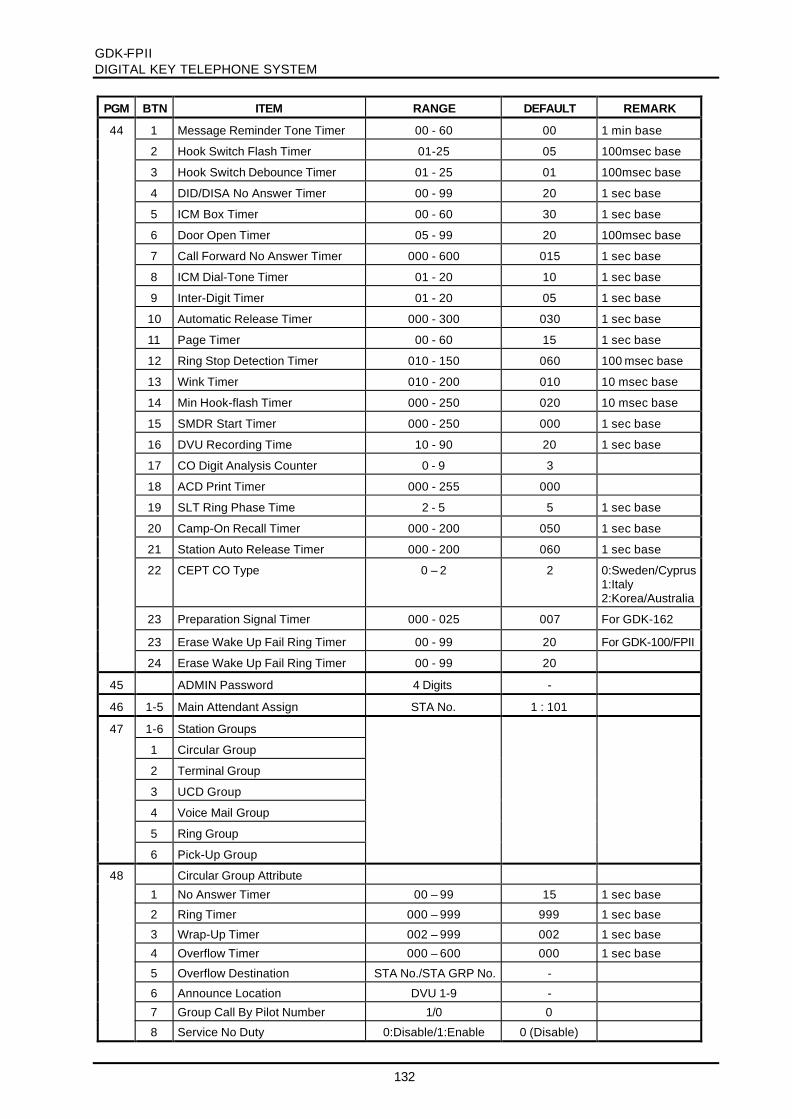
GDK-FPIIDIGITAL KEY TELEPHONE SYSTEM
132
PGM BTN ITEM RANGE DEFAULT REMARK
44 1 Message Reminder Tone Timer 00 - 60 00 1 min base
2 Hook Switch Flash Timer 01-25 05 100msec base
3 Hook Switch Debounce Timer 01 - 25 01 100msec base
4 DID/DISA No Answer Timer 00 - 99 20 1 sec base
5 ICM Box Timer 00 - 60 30 1 sec base
6 Door Open Timer 05 - 99 20 100msec base
7 Call Forward No Answer Timer 000 - 600 015 1 sec base
8 ICM Dial-Tone Timer 01 - 20 10 1 sec base
9 Inter-Digit Timer 01 - 20 05 1 sec base
10 Automatic Release Timer 000 - 300 030 1 sec base
11 Page Timer 00 - 60 15 1 sec base
12 Ring Stop Detection Timer 010 - 150 060 100 msec base
13 Wink Timer 010 - 200 010 10 msec base
14 Min Hook-flash Timer 000 - 250 020 10 msec base
15 SMDR Start Timer 000 - 250 000 1 sec base
16 DVU Recording Time 10 - 90 20 1 sec base
17 CO Digit Analysis Counter 0 - 9 3
18 ACD Print Timer 000 - 255 000
19 SLT Ring Phase Time 2 - 5 5 1 sec base
20 Camp-On Recall Timer 000 - 200 050 1 sec base
21 Station Auto Release Timer 000 - 200 060 1 sec base
22 CEPT CO Type 0 – 2 2 0:Sweden/Cyprus1:Italy2:Korea/Australia
23 Preparation Signal Timer 000 - 025 007 For GDK-162
23 Erase Wake Up Fail Ring Timer 00 - 99 20 For GDK-100/FPII
24 Erase Wake Up Fail Ring Timer 00 - 99 20
45 ADMIN Password 4 Digits -
46 1-5 Main Attendant Assign STA No. 1 : 101
47 1-6 Station Groups
1 Circular Group
2 Terminal Group
3 UCD Group
4 Voice Mail Group
5 Ring Group
6 Pick-Up Group
48 Circular Group Attribute
1 No Answer Timer 00 – 99 15 1 sec base
2 Ring Timer 000 – 999 999 1 sec base
3 Wrap-Up Timer 002 – 999 002 1 sec base
4 Overflow Timer 000 – 600 000 1 sec base
5 Overflow Destination STA No./STA GRP No. -
6 Announce Location DVU 1-9 -
7 Group Call By Pilot Number 1/0 0
8 Service No Duty 0:Disable/1:Enable 0 (Disable)
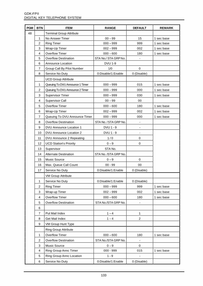
GDK-FPIIDIGITAL KEY TELEPHONE SYSTEM
133
PGM BTN ITEM RANGE DEFAULT REMARK
48 Terminal Group Attribute
1 No Answer Timer 00 – 99 15 1 sec base
2 Ring Timer 000 – 999 999 1 sec base
3 Wrap-Up Timer 002 – 999 002 1 sec base
4 Overflow Timer 000 – 600 180 1 sec base
5 Overflow Destination STA No./ STA GRP No. -
6 Announce Location DVU 1-9
7 Group Call By Pilot Number 1/0 0
8 Service No Duty 0:Disable/1:Enable 0 (Disable)
UCD Group Attribute
1 Queuing To DVU Announce 1 Timer 000 – 999 015 1 sec base
2 Queuing To DVU Announce 2 Timer 000 – 999 000 1 sec base
3 Supervisor Timer 000 – 999 030 1 sec base
4 Supervisor Call 00 – 99 00
5 Overflow Timer 000 – 600 180 1 sec base
6 Wrap-Up Timer 002 – 999 002 1 sec base
7 Queuing To DVU Announce Timer 000 – 999 000 1 sec base
8 Overflow Destination STA No. / STA GRP No. -
9 DVU Announce Location 1 DVU 1 - 9 -
10 DVU Announce Location 2 DVU 1 - 9 -
11 DVU Announce 2 Repeating 1 / 0 0
12 UCD Station’s Priority 0 – 9 0
13 Supervisor STA No.
14 Alternate Destination STA No. /STA GRP No.
15 Music Source 0 – 9 0
16 Max. Queue Call Count 00 - 99 00
17 Service No Duty 0:Disable/1:Enable 0 (Disable)
VM Group Attribute
1 Service No Duty 0:Disable/1:Enable 0 (Disable)
2 Ring Timer 000 – 999 999 1 sec base
3 Wrap-up Timer 002 – 999 002 1 sec base
4 Overflow Timer 000 – 600 180 1 sec base
5 Overflow Destination STA No./STA GRP No. -
6
7 Put Mail Index 1 – 4 1
8 Get Mail Index 1 – 4 2
9 VM Group Hunt Type
Ring Group Attribute
1 Overflow Timer 000 – 600 180 1 sec base
2 Overflow Destination STA No./STA GRP No. -
3 Music Source 0 – 9 0
4 Ring Group Annc Timer 000 - 999 015 1 sec base
5 Ring Group Annc Location 1 - 9 -
6 Service No Duty 0:Disable/1:Enable 0 (Disable)

GDK-FPIIDIGITAL KEY TELEPHONE SYSTEM
134
PGM BTN ITEM RANGE DEFAULT REMARK
48 Pick-Up Group Attribute
1 Auto Pick-Up YES / NO NO
2 All Ringing YES / NO NO
49 1-xx Executive/Secretary Pairs STA No. -
50 1 Alarm Enable YES / NO NO
2 Alarm Mode Alarm / Door-Bell Alarm
3 Alarm Contact Type Close / Open Close
4 Alarm Signal Mode Repeat / Once Repeat
51 1 - x External Contact Assign 1 - 2/4/6 -
52 1 - 5 PBX Dialing Codes Max 2 digits -
53 1 - 5 SMDR Long Distance Codes Max 2 digits 1 : "0"
54 Authorization Codes 5 digits -
55 1 DID Received Digit from PX 2 - 4 3
2 DID First Two Digits Conversion 4 digits #*** 0 - 9# : Ignore Digit* : using received
digit
3 DID Second Digit Conversion 10 digits 1234567890
56 DID/DISA Destination
1 Busy Destination Tone / ATD Tone
2 Error Destination Tone / ATD Tone
57 1 - 4 Pulse Dial Speed Ratio 2 1: 10 PPS 60/402: 10 PPS 66/333: 20 PPS 60/404: 20 PPS 66/33
58 1 Modem Mode Modem / Bypass Modem
2 Modem Baud Rate 1 - 8 4
3 Modem Associated Device CO No.(0)/
STA No.(1)
STA 167/171/291
59 System DATE/TIME Setting
60 1 LCD Time Display Mode 12/24 Hour 12 Hour
2 LCD Date Display Mode MMDDYY /
DDMMYY
DDMMYY
61 S/W Version Display
62 1 Save SMDR YES / NO NO
2 Print SMDR YES / NO NO
3 SMDR Recording Call Type LD / All Long Distance Only
4 Print Incoming Call YES / NO NO
5 Record Detailed SMDR YES / NO YES
6 SMDR Print Baud Rate(RS-232)
1 - 8 6 1: Baud 3002: Baud 6003: Baud12004: Baud 24005: Baud 48006: Baud 96007: Baud 192008: Baud 38400
7 SMDR Currency 3 English Chars -

GDK-FPIIDIGITAL KEY TELEPHONE SYSTEM
135
PGM BTN ITEM RANGE DEFAULT REMARK
63 1 SMDR Cost Per Unit Pulse 6 digits -
2 SMDR Fraction 0 - 5 0
65 1 - 6 TIE Routing Table (01 - 30) CO 01-34/48/96 -
66 1 -12 System Gain Control 0 - 63 1 dB base
67 1 - 3 System Speed Zone 01 - 10
68 1 - 4 ACNR Tone Cadence 0 - 255 20 msec base
69 1 - 4 System Tone Frequency 4 digits
1 - 4 World Time Attribute -
1 Display World Time YES / NO NO (OFF)
2 Celsius/Fahrenheit C/F Celsius (ON)
3 ISD Code Length 1 - 4 3
71
4 ISD Code - 00
1 - 4 World Time
1 Nation Code 3 digits -
2 Area Code 4 digits -
3 Equation of Time 00-23 00
72
4 Temperature 000
73 1 - 9 VM dialing Table Max. 12 digits
74 CO Line Name (01-10) Max. 12 ENG. chars -
75 1 - 4 Ring Frequency 0000 - 9999
76 1 - 4 Distinct Ring Frequency 0000 - 9999
77 1 - 7 DCO TX Gain 00 - 63 1 dB base
78 1 - 3 Digit Insert Table
TABLE 5.6.17 TOLL TABLE
PGM BTN ITEM RANGE DEFAULT REMARK
70 Exception Tables
1 Allowed Table A 01 - 20 -
2 Denied Table A 01 - 10 -
3 Allowed Table B 01 - 20 -
4 Denied Table B 01 - 10 -
64 Canned Toll Exception Table
1 Allowed Table 01 - 10
2 Denied Table 01 - 10
79 CCR Tables 01 - 09

GDK-FPIIDIGITAL KEY TELEPHONE SYSTEM
136
TABLE 5.6.18 PRINT DATABASE
PGM BTN ITEM REMARK
80 1 Print Flexible Numbering Plan
2 Print Slot Assignment
3 Print Station Database
4 Print Flex Buttons Assignment
5 Print CO Line Database
6 Print System Database
7 Print Toll Tables
8 Print System Speed Dial Bins
9 Print All Database
10 Print Specific Nation’s Database
11 Print QSIG Admin Database
TABLE 5.6.19 NATION SPECIFIC SYSTEM PROGRAM
PGM BTN ITEM RANGE DEFAULT REMARK
92 1 CPE CO Connection Program For Australia
2 CPE Port Selection Program 0 - 1 -
3 CLI TEL No. or Name Display 0 - 1 0
TABLE 5.6.20 SYSTEM ATTRIBUTE – V
PGM BTN SUB-
BTN
ITEM RANGE DEFAULT REMARK
#1 1 Virtual DIP Switch For GDK-FPII only
1 CTS ON/OFF OFF
2 SOFT ON/OFF OFF
3 ECHO ON/OFF OFF
4 XONOFF ON/OFF OFF
2 1-5 Assign MOH via SLT Station No
6 1-8 Print Port Selection 1-2(4) 1

GDK-FPIIDIGITAL KEY TELEPHONE SYSTEM
137
APPENDIX A. The Maximum Number of Boards in a system
The maximum number of boards is described in this section. Some boards can be limited by thecapacity of system power supply, PSU linear.
A.1 The Maximum Number of Cards in a system..The maximum capacity of boards in a system is given in table A.1 Not all maximum capacities may be
achieved simultaneously. The complex configuration can be limited by the system power supply, e.g.PSU(linear). Especially if you want to make the complex configuration with various extensionboards including WTIB and 2B-modules, consult it with its supplier or authorized agent.
Table 1.1 The maximum number of cards per a cabinet
Board Name The Maximum Numberof Cards per a cabinet
Slot Position Remark
2BRI 1 3 Basic slot 4LCO 1 3 Basic slot 4SLI 1 2 Basic slot AC15(UK) 4 4~7 BWDIDB(NZ) 4 4~7 DTIB 4 4~7 DVIB 2 1,4~7 ETIB 4 4~7 LCOB 4 4~7 MBU 1 KSU PRI 1 3 Basic slot SLIB 4 4~7 STIB 5 1,4~7 TLIB(KOREA) 4 4~7 WTIB 1 1,4~7 WTIU 1 on WTIB 2B-SLIU30 and SLT 24 on LKD30 * Note 1l Note;
1. The 2B-modules are limited by the power capacity.The maximum terminals with PSU(Linear) are limited by 34 without WTIB and 48 with WTIB,because of its power capacity.The maximum terminals with PSU2(SMPS) are limited by 48 without WTIB and 64 with WTIB,because of its power capacity.
A.2 The Capacity of GDK-FPII Power SupplyThe capacity of GDK-FPII Power Supplies, PSU(linear) and PSU2(SMPS), is given in table A.2. The
capacity of +30Vdc in table A.2 includes the capacity of +5Vdc,-5Vdc. -48Vdc is locally generated on thecard that it is required.
Table A.2 Power Capacity of GDK-FPII PSU and PSU2
PSU +5Vdc -5Vdc +30Vdc -48Vdc GDK-FPII PSU (Linear) 2000 500 3000 None GDK-FPII PSU2(SMPS) 3500 800 4000 Nonel Note:
Manufacturing GDK-FPII PSU(linear) will be officially stopped after launching PSU2(SMPS) fromthe first half of 1999.

GDK-FPIIDIGITAL KEY TELEPHONE SYSTEM
138
APPENDIX B. Power Consumption
Board Name The Power Consumption/a Card(all boards) +5V -5V +30V -48V
2BRI 55 0 0 04LCO 85 65 80 04SLI 55 50 135 0
AC15(UK) 65 55 0 0BWDIDB(NZ) 100 60 490 0DTIB 50 0 360 0
DVIB 475 5 0 0ETIB 65 55 410 0LCOB 100 70 80 0
MBU 360 15 370 0PRI 125 0 0 0SLIB 80 65 195 0
STIB 120 0 150 0TLIB(KOREA) 60 35 280 0WTIB 680 0 320 0
WTIU 200 0 320 02B-SLIU30 and SLT 0 0 50 0
MEMU 3 0 0 0
SMEMU 5 0 0 0PLLU2(issue 1,2) 20 0 0 0PLLU2(issue 3) 30 0 0 0
MODU 15 7 0 0SIU(UK) 58 0 0 0SIU(ST) 15 0 0 0
CMU 8 3 0 0
PFTU(External) 0 0 55 0PFTU-I(Internal) 0 0 25 0
RGU 0 0 110 0Charging Battery 0 0 500 0

GDK-FPII DIGITAL KEY TELEPHONE SYSTEM
139
APPENDIX C. PSU installation This is the description of PSU(linear type) for the user who uses it.
Note: There are 2 kinds of PSUs, PSU which is a linear type of Power supply Unit, and PSU2 which is a SMPS. The production of PSU (linear) has been officially stopped after replacing with PSU2(SMPS) in the 1st half of 1999.
The PSU is basically installed when delivering the system. But if PSU is replaced with new one, assure that the AC power cord is NOT plugged into the AC outlet before installing new one. The system contains any one of two linear PSU assemblies; one is PSU with transformer 6170NI0008A, the other is PSU with transformer 6170NI0007A PSU with Main Transformer 6170NI0008A: for European and Oceanic countries The linear type PSU can operate from 220VAC~240VAC with transformer 6170NI0008A based on the connection of the cable(2-wired) from transformer to the connector CN1 of the PSU PCB. This type only operate from 220~240VAC, not 110VAC. Fuse: T1.6AH250V PSU with Main Transformer 6170NI0007A: for the countries except European and Oceanic countries. The linear type PSU can be operate from ether 110VAC or 220VAC with transformer 6170NI0007A based on the connection of the cable(5-wired) from transformer to the connector CN1 or CN2 of the PSU PCB. Generally shipped the PSU with 220VAC. If local AC voltage 110~127VAC volts, move the cable to the CN2 shown as Figure C.1
Input Voltage Connect to Fuse 110VAC CN2 T3.15AL250V 220VAC CN1 T1.6AH250V
Figure C.1 Connection of PSU linear

GDK-FPII DIGITAL KEY TELEPHONE SYSTEM
140
After the PSU installation, you have to assemble the cover with three(3) screws. The cover assembling method is shown in Figure C.2
Figure C.2 Power Supply Unit Cover Assembly

GDK-FPIIDIGITAL KEY TELEPHONE SYSTEM
141
APPENDIX D. GDK-PHU Installation
1. Introduction
-. This manual provides the information necessary to install the PHU of GDK with GDK system.(The packing of GDK-PHU may be different by country adaptation.)
-. This product is the PHU(Power Harmonic filter Unit), Input is AC 90 ~ 260V under single phase.-. It used to GDK-FPII KSU for meet to EN61000-3-2.
(EN61000-3-2 : Limit for harmonic currents emissions)-. The packing of GDK-PHU may be different by country adaptation. But the country listed
below is adaptable as follows;※ Country Adaptation : Belgium, Denmark, Finland, Ireland, Italy, Netherlands, Norway,
Poland, Spain, Sweden, United Kingdom
2. Installation
3. Specification
Item Specification Remark
1. Input Voltage AC 90V ~ 260V
2. Input Frequency 50/60Hz
3. Input Current Max. 4A4. Test voltage Between AC Mains and Chassis
3KV AC
1 2 3
● Put on screw the PHU at side of KSU like figure.
● Insert the cord of PHU at the PSU like figure.
● Insert power cord of external power source at the PHU like figure.

GDK-FPII DIGITAL KEY TELEPHONE SYSTEM
142
APPENDIX E. Declaration of Conformity
GDK-FPIIDIGITAL KEY TELEPHONE SYSTEM
143
Alpha-Numeric INDEX
2B-module ....................................................................................................................... 36
A
AC15 Board Installation - UK................................................................................................. 67AC15 Board wiring - UK ........................................................................................................ 94AC15 Board(AC15 private Line Interface Board) - UK ............................................................. 26ADMIN PROGRAMMING INDEX..........................................................................................119ADPU (ADPCM unit)............................................................................................................. 32Add-on boards .................................................................................................................. 29Alarm Detection wiring .......................................................................................................... 81Analog CO Line Board Installation ......................................................................................... 64Analog CO line Boards.......................................................................................................... 25Analog CO line wiring............................................................................................................ 93
B
BRI Line Termination Board (GDK-162/100 TERM: 2923NP1656A) ......................................... 38BWDIDB (Both-way Direct Inward Dialing Board) - New Zealand ............................................. 27BWDIDB Installation - New Zealand....................................................................................... 68BWDIDB wiring - New Zealand .............................................................................................. 95Back-Board Installation ......................................................................................................... 46Battery Back-Up Wiring......................................................................................................... 76
C
CMU (Call Metering Unit) ...................................................................................................... 32CO LINE BASE PROGRAM ................................................................................................ 130CPTU (Call Progress Tone Detection Unit: CPTU/A, CPTU/B) ................................................. 32Cables (5MC1, 5MC2) .......................................................................................................... 38Changes In Service.................................................................................................................9Clock Control Connection- Multi ISDN board installation........................................................ 105Contact Assignments of RJ21 Type Connector for Basic Connection........................................ 81Contact Assignments of RJ21 Type Connectors for Expansion connection. .............................. 90Contact Assignments of RJ21 type connectors on Analog CO line board.................................. 97Contact Assignments of various types of connectors ..............................................................110
D
DEFAULT VALUES - PROGRAMMING ................................................................................ 121DMEU/DMEU4 (DRAM Memory Expansion Units).................................................................. 32DTIB (Digital Terminal Interface Boards)................................................................................. 23DTIB Installation .................................................................................................................. 61DTRU (DTMF Receiver Unit)................................................................................................. 31DTRU Installation ................................................................................................................. 64DVIB (Digitized Voice Interface Board) ................................................................................... 22DVIB Installation .................................................................................................................. 74Digital Keyset and Terminal wiring.......................................................................................... 83Digital Keysets and Terminals................................................................................................ 33

GDK-FPIIDIGITAL KEY TELEPHONE SYSTEM
144
E
EMERGENCY SERVICE CALL ........................................................................................... 126ETIB (Electronic Terminal Interface Board)............................................................................. 23ETIB Installation .................................................................................................................. 62Electronic Keyset and Terminal wiring.................................................................................... 85Electronic Keysets and Terminals .......................................................................................... 34Extension Board Installation .................................................................................................. 61Extension Board wiring.......................................................................................................... 83Extension Boards ................................................................................................................. 23External Music Source wiring................................................................................................. 79External Paging Port and General Purpose Relays wiring........................................................ 80External Paging wiring .......................................................................................................... 79
F
FLEXIBLE BUTTONS PROGRAM ....................................................................................... 129FLEXIBLE DID TABLE PROGRAM...................................................................................... 126FLEXIBLE NUMBERING PLAN – GDK-100.......................................................................... 122FLEXIBLE NUMBERING PLAN – GDK-162.......................................................................... 121FLEXIBLE NUMBERING PLAN – GDK-FPII......................................................................... 124
G
GDK-PC PHONE (CTI) ......................................................................................................... 37General Site Consideration.................................................................................................... 45
H
Hearing Aid Compatibility ...................................................................................................... 10
I
INITIALIZATION - PROGRAMMING ................................................................................... 121ISDN 2BRI ( Basic Rate T Interface) Installation ..................................................................... 68ISDN 2BRI (Basic Rate Interface Board: T interface only)........................................................ 28ISDN 2BRI wiring................................................................................................................ 101ISDN Basic Information........................................................................................................112ISDN Board Installation......................................................................................................... 68ISDN Boards .................................................................................................................. 27ISDN COLP TABLE ASSIGNMENT..................................................................................... 127ISDN Other Information........................................................................................................113ISDN PRI ( Primary Rate Interface) Installation....................................................................... 73ISDN PRI (Primary Rate Interface Board)............................................................................... 27ISDN PRI wiring ................................................................................................................ 103ISDN STIB ( Basic Rate S/T Interface) Installation.................................................................. 70ISDN STIB (S/T Basic Rate Interface Board: switchable S/T interface)..................................... 28ISDN STIB wiring................................................................................................................ 102ISDN Station/CO Line Number Assignments .........................................................................113ISDN wiring .................................................................................................................. 98Incidence Of Harm..................................................................................................................9Intercom/Door Phone Box installation..................................................................................... 88

GDK-FPIIDIGITAL KEY TELEPHONE SYSTEM
145
K
KSU (Key Service Unit)......................................................................................................... 20KSU Grounding .................................................................................................................. 51KSU INSTALLATION............................................................................................................. 47Keyset & Terminals............................................................................................................... 33
L
LCOB/4LCO (Loop Start CO Line Interface Board) ................................................................. 26LCOB/4LCO Installation ........................................................................................................ 65LCOB/4LCO wiring ............................................................................................................... 93LCR TABLE ASSIGNMENT................................................................................................. 126
M
MBU (Main Board Unit) ......................................................................................................... 20MBU Installation .................................................................................................................. 56MBU wiring .................................................................................................................. 78MEMU (Memory Expansion Unit)........................................................................................... 29MEMU Installation................................................................................................................. 59MODU (Modem Unit) ............................................................................................................ 30MODU Installation................................................................................................................. 60MSGU (Message Wait Unit)................................................................................................... 31MSGU Installation................................................................................................................. 64MSN/SUB-ADDRESS ASSIGNMENT.................................................................................. 126Maintenance Limitations........................................................................................................ 10Miniature 6-position jack.......................................................................................................110Miniature 8-position jack for ISDN connection........................................................................111Mounting KSU .................................................................................................................. 48
N
NUMBERING PLAN.............................................................................................................115Notice Of Radiated Emissions ............................................................................................... 10Notice Of Replacement with Lithium Battery ........................................................................... 10
P
PCB Handling & General Installation...................................................................................... 54PCB INSTALLATION............................................................................................................. 54PFTU Installation .................................................................................................................. 50PFTU Wiring .................................................................................................................. 91PFTU/PFTU-I (Power Failure Transfer Unit) ........................................................................... 21PLLU2 (Phase Locked Loop Unit2) ........................................................................................ 31PLLU2 Installation................................................................................................................. 60PRINT DATABASE - PROGRAMMING ................................................................................ 137PROGRAMMING - INTRODUCTION....................................................................................114PROGRAMMING - PERMANENT UPDATE PROCEDURE ....................................................115PROGRAMMING - TO ENTER THE PROGRAMMING MODE................................................114PSU (Power Supply Unit)...................................................................................................... 20PSU Installation .................................................................................................................. 52PURPOSE .........................................................................................................................9

GDK-FPIIDIGITAL KEY TELEPHONE SYSTEM
146
QQSIG connection................................................................................................................ 109
RREGULATORY INFORMATION...............................................................................................9RGU (Ring Generator Unit) ................................................................................................... 21RGU Installation .................................................................................................................. 49RJ21 type connectors ..........................................................................................................110RS-232C WIRING on SIU ..................................................................................................... 77Relay Contacts for General Purpose...................................................................................... 80
SSITE PREPARATION............................................................................................................ 45SIU (Serial Interface Unit)...................................................................................................... 31SIU Installation .................................................................................................................. 60SLIB/4SLI (Single Line Interface Boards)................................................................................ 24SLIB/4SLI Installation............................................................................................................ 63SLOT ASSIGNMENT ...................................................................................................... 125SMEMU (Security Memory Expansion Unit)............................................................................ 30SMEMU Installation .............................................................................................................. 59STATION BASE PROGRAM ............................................................................................... 127STATION LINK PROGRAM ................................................................................................. 129SYSTEM ATTRIBUTE - IV................................................................................................... 127SYSTEM BASE PROGRAM................................................................................................ 131SYSTEM COMPONENTS ..................................................................................................... 20SYSTEM SPECIFICATIONS ................................................................................................. 17SYSTEM WIRING................................................................................................................. 76Single line Telephone wiring .................................................................................................. 87System Capacity .................................................................................................................. 12System Configuration Chart................................................................................................... 13System Configuration Chart - Typical ..................................................................................... 14System Configuration Chart with PRI Line .............................................................................. 15System Configuration Chart without PRI Line ......................................................................... 16
TTLIB (Tie Line Board) -Korea................................................................................................. 26TLIB Installation - Korea........................................................................................................ 67TLIB wiring - Korea ............................................................................................................... 96TOLL TABLE - PROGRAMMING......................................................................................... 136Telephone Company Notification..............................................................................................9Terminating Resistors on Basic Rate interface(2BRI/STIB).................................................... 104Test Accessories for the Purpose of Test................................................................................ 38Trace Tool (GDK-TRC1)........................................................................................................ 38
V
Verify On-Site Equipment ...................................................................................................... 46
W
WTIB /WTIU (Wireless Terminal Interface Board / Unit)........................................................... 25
Copyright © 2022 FDOKUMEN