68 KEY TELEPHONE SYSTEM DIALOG* INTERCOM SYSTEM
85
• ( ( BELL SYSTEM PRACTICES AT&TCo Standard SECTION 518-411-100 Issue 2, June 1980 68 KEY TELEPHONE SYSTEM DIALOG* INTERCOM SYSTEM CONTENTS PAGE 1. GENERAL 2 2. DESCRIPTION 2 SYSTEM 2 572Al KSU 4 KEY TELEPHONE UNITS 6 A. 484A KTU-Station Interface Circuit 6 B. 485A KTU-Controller Circuit 7 C. 486A KTU-System Service Circuit 7 D. 487A KTU-Battery Feed Circuit 8 E. 488A KTU-Line Interface Circuit F. 489A KTU- TOUCH-TONE Decoder Circuit 184C 1 BACKBOARD 3. INSTALLATION ORDERING GUIDE A. Basic System B. Optional Features 572A1 KSU KEY TELEPHONE UNITS TELEPHONE SETS OFF-PREMISES EXTENSIONS 8 9 9 9 9 9 9 12 13 13 21 NOTICE CONTENTS PAGE EXTERNAL SIGNALING OR LOUD RINGING BELLS 21 4. OPERATION-STANDARD FEATURES 21 INTERCOM LINE PICKUP AND HOLD 21 SUPERVISORY FLASH FEATURES 28 DIAL-ACTIVATED FEATURES 28 A. Flexible Dial Conferencing 28 B. Do-Not-Disturb (DND) 29 C. Call Forwarding 29 D. Call Forwarding-Do-Not-Disturb 30 AUTOMATIC CALLBACK (ACBK) 30 CALL SCREENING 31 OVERRIDE (OVRD) 31 REMOTE ANSWER (REAN) 31 5. OPERATION-OPTIONAL FEATURES 32 FOUR LINKS 32 TOUCH-TONE SETS 32 HANDS-FREE ANSWER ON INTERCOM (HFAI) 32 PAGING ACCESS 33 *Trademark of AT&T. Not for use or disclosure outside the Bell System except under written agreement Printed in U.S.A. Page 1
-
Upload
khangminh22 -
Category
Documents
-
view
1 -
download
0
Transcript of 68 KEY TELEPHONE SYSTEM DIALOG* INTERCOM SYSTEM

•
(
(
BELL SYSTEM PRACTICES AT&TCo Standard
SECTION 518-411-100 Issue 2, June 1980
68 KEY TELEPHONE SYSTEM
DIALOG* INTERCOM SYSTEM
CONTENTS PAGE
1. GENERAL 2
2. DESCRIPTION 2
SYSTEM 2
572Al KSU 4
KEY TELEPHONE UNITS 6
A. 484A KTU-Station Interface Circuit 6
B. 485A KTU-Controller Circuit 7
C. 486A KTU-System Service Circuit 7
D. 487A KTU-Battery Feed Circuit 8
E. 488A KTU-Line Interface Circuit
F. 489A KTU-TOUCH-TONE Decoder Circuit
184C 1 BACKBOARD
3. INSTALLATION
ORDERING GUIDE
A. Basic System
B. Optional Features
572A1 KSU
KEY TELEPHONE UNITS
TELEPHONE SETS
OFF-PREMISES EXTENSIONS
8
9
9
9
9
9
9
12
13
13
21
NOTICE
CONTENTS PAGE
EXTERNAL SIGNALING OR LOUD RINGING BELLS 21
4. OPERATION-STANDARD FEATURES 21
INTERCOM LINE PICKUP AND HOLD 21
SUPERVISORY FLASH FEATURES 28
DIAL-ACTIVATED FEATURES 28
A. Flexible Dial Conferencing 28
B. Do-Not-Disturb (DND) 29
C. Call Forwarding 29
D. Call Forwarding-Do-Not-Disturb 30
AUTOMATIC CALLBACK (ACBK) 30
CALL SCREENING 31
OVERRIDE (OVRD) 31
REMOTE ANSWER (REAN) 31
5. OPERATION-OPTIONAL FEATURES 32
FOUR LINKS 32
TOUCH-TONE SETS 32
HANDS-FREE ANSWER ON INTERCOM (HFAI) 32
PAGING ACCESS 33
*Trademark of AT&T.
Not for use or disclosure outside the Bell System except under written agreement
Printed in U.S.A. Page 1

SECTION 518-411-100
CONTENTS PAGE
CO/PBX UNE ACCESS 33
ATTENDANT RECALL 35
6. MAINTENANCE 35
A. Feature Sequence Charts 35
B. Trouble Analysis Charts 35
c. Diagnostic Test Sequence 35
1. GENERAL
1.01 This section provides description, installation, connection, operation, and maintenance
information for the 6B Key Telephone System (KTS).
1.02 This section is reissued to add information on:
• New 554BMS and 2554BMS telephone sets
• New 324A adapter for external ringing in noisy locations
• Wiring modification of the following telephone sets for use with 6B KTS:
830/2830FM telephone sets
TOUCH-A-MATIC® (872-/2872-) telephone sets
TRIMLINE® telephones
Jack equipped CALL DIRECTOR® telephones.
1.03 This issue of the section is based on SD-69946-01, Issue 1. If this section is to
be used with equipment or apparatus reflecting later issues of the drawings, reference should be made to the SDs and CDs to determine the extent of the changes and the manner in which the section may be affected.
2. DESCRIPTION
SYSTEM
2.01 The 6B KTS is a fully electronic intercom which has a capacity of four separate talking
Page 2
paths (links) and 52 station codes. Up to eight CO/PBX calls can be answered, held, or transferred but CO/PBX calls cannot be originated using the 6B KTS.
Note: More than 52 stations can be installed by having stations share a code. Only two stations per code are permitted and only even numbered codes should be bridged. With this limitation, there can only be six sets served per station circuit (484A key telephone units [KTUS]).
2.02 All required KTUs are mounted in a 572A1 key service unit (KSU). The KSU includes
an integral 206A power supply, but 24-volt direct current (de) and 10-volt alternating current (ac) and their associated grounds must be supplied from the associated key system or a separate power supply.
2.03 All wmng, except power, is brought into the 572A1 KSU through connector cables
plugged into the rear of the unit (Fig. 1). An optional 184C1 backboard has been developed as a terminal field for the 6B KTS, or existing blocks in the yellow field of a centralized key system can be used.
2.04 The 6B KTS can be added as an adjunct to any KTS using A -lead control such as the
1A1 or 1A2 KTS. Only one button is required on key telephone sets (rotary dial or TOUCH-TONE® dial). Modification of the HOLD key wiring and a separate 10-volt ac buzzer are required in the telephone sets used with the 6B KTS. Nonkey sets •which can be modified for A-lead control, may• be used but they will not supply those features involving the HOLD key. •A new 554/2554BMS wall telephone set has been introduced as an intercom only instrument for the 6B KTS. This set does not need modification of wiring as do all the other key and nonkey sets used with the 6B KTS. A 500/2500MM or a 502/2502BM telephone set may be used as an intercom only set where the wall set is not applicable. •
2.05 •Loud or external ringers may be added to the 6B KTS with the use of the 324A
adapter. Off-premises stations may be added to the 6B KTS but require a separately provided long-line circuit .•
{
(

ISS 2, SECTION 518-411 - 1 00
POWER CONNECTOR
FRAME GROUND TERMINAL
Fig. 1- .572A 1 KSU (Rear View).
2 .06 The basic system provides the following features:
• Intercom call progress tones such as dial tone, ringback, error tone, etc
• Ringing- the intercom audible is blocked at stations •busy on CO/PBX calls•
• 3- or 4-party conferencing
• Do-not-disturb (DND)
• Call transfer
• Call add-on
• Station and consultation HOLD
• Two-link operation- the register IS held during dialing only
• System busy indication
• Privacy-except when override ts activated
• Single button appearance on key telephone sets
• Call forwarding
Page 3

SECTION 518-411-100
• Override-permits certain stations to bridge onto an established intercom connection or override DND
• Remote answer-permits user at one station to intercept and answer a call intended for a second station
• Automatic callback-enables a user who dials a busy station to program the system to call back when both stations are idle and a link is available.
2.07 Additional features that cart be supplied on an optional basis are:
• Additional links-to a maximum of four
• Paging access
• The CO/PBX line access when the line is in the ringing or hold state
• Attendant recall
• Hands-free answer on intercom (HF AI) and voice signaling using a separate station adjunct
• TOUCH-TONE service
• Off-premises stations
• •External signaling .•
2.08 Features (standard and optional) are activated by operation of the station HOLD key, line
switch flashing, or by dialing a specified code (Table A). Refer to Part 4 and 5 for complete operation information.
2.09 Call progress tones, indicating that an action is required by the user or that the feature
has been activated, are returned to the originator as required (Table B). Cancellation of dial-activated features, where required, is accomplished by dialing the code of the station that originally activated the feature. This must be done from the originating station.
Page 4
SYSTEM CODE ASSIGNMENTS
CODE FUNCTION
00 Attendant Recall
01 Override
02 Call Forwarding
03 Three-Party Conference
04 Four-Party Conference
06 Do-Not-Disturb
07 Remote Answer
09 Automatic Callback
10-11 Station Codes (2-Station Override)
10-19 Station Codes (10-Station Override)
20-61 Station Codes (10-Station Override)*
20-69 Station Codes (2-Station Override)*
70-73 Paging Access*
80-87 CO /PBX Line Access
* Codes 50-53 will not be available for station codes when paging access is provided. These codes become 70-73. See Fig. 39 for further details.
572A1 KSU
2.10 The 572Al KSU consists of:
• 727A panel equipped with connectors for 22 KTUs
• Plug-in KS-21651, L4 fuseboard
• Fourteen microribbon plugs (PO is not used in this system)
• Terminal board for incoming power connections
• 206A power supply
•
(

(
(
(
TONE
Intercom Diat Tone (IDT)
Intercom Audible Ringback (IAR)
Intercom Busy Tone (IBT)
Error Tone (ET)
Acknowledgment Tone (AT)
Reminder Tone (R T)
Override Tone (OT)
Hold Tone (HT)
• •Two option switches:
Paging access
Override .•
ISS 2, SECTION 518-411-100
TABLE B
CALL PROGRESS TONES
SIGNAL HEARD REMARKS
128 Hz continuous
256Hz interrupted; If any station is equipped with a 2A 1 second on, 3 HF AI unit, IAR consists of a single seconds off spurt (1 second) of 128-Hz time.
128Hz interrupted at 1/2-second intervals
256/512 Hz alter- Tone heard when errors are made in nating at 1/2-second setting up dial-activated features. intervals Indicates procedure must be restarted.
128 Hz for 250 ms Tone heard when feature has been properly activated or canceled. Also heard on paging access calls.
128 Hz interrupted Tone heard at start of all calls, followed at 75 ms intervals by dial tone at stations that have
· for 1-1/4 seconds; activated CFWD, ACBK, or DND as a then continuous reminder that feature is in effect. 128Hz
128 Hz for 500 ms Tone heard by both parties of a conver-sation when a station exercising OVER-RIDE is bridged on-line.
Four bursts of Tone heard when switchhook is flashed 128-Hz tone during a call. Hold tone is always
followed by steady dial tone.
2.11 The 206A power supply is mechanically linked to the 727 A panel of the KSU. Interconnection
is made through a cable from the panel which is plugged into the power supply.
2.12 The 572Al KSU mounts on 23-inch mountings Twelve microribbon plugs (P1 through P12) on the rear of the KSU accept A25B connector cables which are routed to the 184Cl backboard or the yellow field of centralized key system installations. A P13 also accepts one A25B connector cable but is routed to pick up the incoming CO/PBX lines. The fuseboard on the KSU protects the 10-volt ac and 24-volt de circuits (Table C). A light emitting diode (LED) on the board indicates operation of any fuse.
and requires 13 inches of vertical space. It can be mounted in a 16C apparatus mounting with the center bar removed, or it can be rack-mounted. When mounted in a 16C apparatus mounting, a 117C cover can be provided.
2.13 Refer to Fig. 2 for the location of the KTUs in the 572Al KSU and the location of major
components.
Page 5

SECTION 518-411-100
tTABLE Ct
FUSE ASSIGNMENTS-572A1 KSU
LOCATION FUSE TYPE
1
2
3
4
5
6
7 70H
KS-21651L4 Fuseboard 8
9
10
11
12
13
14 70G
15
1 24F
2
3 206A Power Unit 24C
4
5 24E
MDL 2 BUSSMAN
KEY TELEPHONE UNITS
2.14 The KTUs employed in the 6B KTS are all 8-inch SO-contact boards. All but the 488A
KTUs occupy a single-width (3/4 inch) position. The 488A KTUs require a double-width position.
Page 6
CAPACITY FUNCTION
10-volt ac-Station KTU in J6
10-volt ac-Station KTU in J7
10-volt ac-Station KTU in J8
10-volt ac-Station KTU in J9
10-volt ac-Station KTU in J10
10-volt ac-Station KTU in Jll
3/4 Ampere 10-volt ac-Station KTU in J12
10-volt ac-Station KTU in J13
10-volt ac-Station KTU in J14
10-volt ac-Station KTU in J15
10-volt ac-Station KTU in J16
10-volt ac-Station KTU in J17
10-volt ac-Station KTU in J18
-24 volt dc-572A1 KSU 1/2 Ampere
Spare
-5 volt de (Logic) for J1-J8 5 Ampere
-5 volt de (Logic) for J9-J25
-10 volt de 2 Ampere
+10 volt de
1/2 Ampere RAM ground
2 Ampere 110-volt ac input
The system options and method of application are shown in Table D.
A. 484A KTU-Station Interface Circuit
2.15 The 484A KTUs are installed in jacks 6 through 18, depending on the station codes
(

(
(
ISS 2, SECTION 518-411-1 00
J1 J2 J3 J4 J5 J8 J7 JB J9 J10 J11 J12 J13 J14 J15 J1B J17 J18 J19A J21A J23A J25A J27 A A A A A A A A A A A A A A A A A A
* * * * *
('I) ..... (\j ID CD ('I) ..... :;: ID CD ('I) ..... a; :::2 :::2 :::2 :::2 :::2 I I C\1 C\1 ('I) ('I) • • ID ID C\1 • (Q CD ~ ~ ~ ~ ~ I I I I I I I I I I I I I I I • llll: llll: llll: llll: llll: 0 • CD C\1 (Q 0 • CD C\1 (Q 0 • CD ...... ('I) ID ..... ......
c: ...... ...... ...... C\1 C\1 ('I) ('I) ('I) • • ID ID ID u; c: c: c: c: w w w w CD ID CD ..... ..... c: c: c: c: c: c: c: c: c: c: c: c: c: z z z z (Q CD CD CD CD CD ~ ~ ~ ~ ~ ~ ~ ~ ~ ~ ~ ~ ~ .... .... .... .... (\j • • • • • Cl) Cl) Cl) Cl) Cl) Cl) Cl) Cl) Cl) Cl) Cl) Cl) Cl) ...... ...... ...... ......
I Cl)
484A KTU ~ 488A KTU ____. llll:
J1 J2 J3 J4 J5 Jsl J71 Jsl J9,J1ojJ111J121J131J14j J151 J1sj J171 J18 J198,J21B,J238,J25B .8 B B B B B B B B B B B B B 8 8 B B
484A KTU-STATION CIRCUIT 485A KTU-CONTROLLER CIRCUIT 48BA KTU-SERVICE CIRCUIT 487A KTU-BATTERY FEED CIRCUIT
* SEE PARAGRAPH 4.20 FOR OPTIONAL OVERRIDE STATION CODE ASSIGNMENTS
* SEE PARAGRAPH 5.08 FOR OPTIONAL PAGING * ACCESS CODES
208A POWER UNIT
488A KTU-LINE INTERFACE CIRCUIT 489A KTU-TOUCH-TONE DECODER
CIRCUIT KS-21B51L4-FUSEBOARD
Fig. 2-·572A I KSU Orcuit Pack Layout (Front View).
being installed. Each KTU contains the circuitry for four station codes. The 484A controls the station visual and audible signals from signals received over the H, B, and A leads, and also controls the station busy and station hold features. Control of the seized intercom link is also through the station circuit.
Note: Power interruptions greater than 1.7 seconds will release any calls in progress. Stations that are off-hook when the power is restored will be out of service until they go on-hook momentarily.
B. 485A KTU-Controller Circuit
2.16 The controller circuit processes the calls and features through the system. Contained
on the board are the central processing unit, memory, timing circuits, and the -10 volt voltage regulator. The 485A KTU is installed in J.2.
C. 486A KTU-System Service Circuit
2.17 The service circuit performs the following functions:
• Generates required system tones
• Switches the tones to the talking links
• Interfaces the control signals from the line and station circuits to the controller
• Switches the TOUCH-TONE receiver to the talking links as required
• The timing generator produces timing signals required by the system, such as lamp flash and lamp wink, and also sets other system timing standards.
Refer to Table B for an outline of the tones used in the 6B KTS. The 486A KTU is installed in J3.
Page 7

SECTION 518-411-100
tTABLE D.
68 KEY TELEPHONE SYSTEM OPTIONS
OPTION KTU OPTION PLUG OR SWITCH POSITION
T-Continuous Ring A-B (1st and 2nd stations)
484A D-E (3rd and 4th stations)
V-Interrupted Ring (Note 1)
B-C (1st and 2nd stations) E-F (3rd and 4th stations)
W-Single-Spurt Audible Ringback 486A A-B, D-E
X-Repeated Audible Ringback (Note 2)
B-C, E-F
Y-Fast Disconnect (CSBR) B-C,(1st circuit) E-F (2nd circuit)
488A Z-Slow Disconnect (ESS Office) A-B (1st circuit)
D-E (2nd circuit)
S-Without Paging Access Paging Access Switch Switch OFF (factory-provided)
R-With Paging Access (Note 3)
Switch ON
N-Two Station Override Override Switch "10-11" (factory-provided)
Q-Ten Station Override (Note 3)
"10-19"
Note 1: If hands-free answer on intercom (HF AI) is provided, install option T for station involved. If one of paired circuits has option T, other stations will have it.
Note 2: If any station has HF AI, system must have option W.
Note 3: The paging access and override option switches are located on the rear of the 572A1 KSU.
D. 487A KTU-Battery Feed Circuit
2.18 Each 487 A KTU provides the de voltages for two links. The KTU for the first two
links is installed in J4; if a third and fourth link is provided, another KTU must be installed in J5. The 487 A KTU also provides a LED for call supervision and dial pulse detection.
E. 488A KTU-Line Interface Circuit
2.19 The 488A KTU provides limited access to the CO/PBX lines. One 488A KTU is
Page 8
required for each two lines to perform the following functions:
• Isolate the 6B KTS from CO/PBX line potentials
• Detect and acknowledge supervisory signals from the line
• Transfer control information on the A and L leads from the CO/PBX line circuit to the controller circuit.
The 488A KTUs are installed in jacks J19, J21, J23, and J25, as required. These KTU s occupy double-width jack positions.
('
(

r··
(
F. 489A KTU-TOUCH-TONE Decoder Circuit
2.20 The 489A KTU performs the function of interpreting the tone address signals from
the station dial. The frequency detectors of the 489A KTU convert the information to bits which are processed by the controller circuit. The controller resets the TOUCH-TONE receiver after each dialed digit in preparation for subsequent dialing. The optional 489A KTU is installed in Jl.
184C1 BACKBOARD
2.21 The optional184Cl backboard (Fig. 3) consists of a yellow backboard equipped with a
14A2-125 terminal block, providing terminations for eight CO/PBX lines and 20 stations (Fig. 4). Space is provided for the addition of two more terminal blocks which must be separately ordered. Addition of the second block adds capacity for 25 more stations. Addition of the third block adds the final stations. The 184Cl backboard offers a convenient method of grouping the 6B KTS terminations, but is not required if the yellow field of a centralized key system installation can be utilized.
2.22 The 14A2-125 terminal blocks used with the 184Cl backboard consist of a 66-type
connecting block wired to five microribbon plugs. The plugs accept A25B connector cables to provide connections between the backboard and the 572Al KSU. The layout of the 184Cl backboard and the plugs to be used in connecting to the 572Al KSU is shown in Fig. 4. All station connections and the A and lamp leads from the station side of the line circuits are made on the terminal blocks of the 184Cl backboard. Tip and ring of the CO/PBX lines (from ahead of the line circuit) are fed through a separate cable to P13 on the KSU.
3. INSTALLATION
ORDERING GUIDE
A. Basic System
• Unit, Key Service, 572Al-one required per system. Where desired, the 572Al KSU can be mounted in a 16C apparatus mounting with a 117C cover. These items must be separately ordered.
ISS 2, SECTION 518-411-100
• Backboard, 184Cl-equipped with one 14A2-125 terminal block. Order one per system when yellow field of centralized system is not used. Has terminations for eight CO/PBX lines (A and L leads) and 20 stations.
• Block, Terminal, 14A2-125-order one to add additional25 stations to 184Cl backboard. Order second block to extend number of stations over 45.
• Cable, Connector, A25B-order as required for connections between 572Al KSU and 184Cl backboard or yellow field. Cables used with 184Cl backboard must be double-ended.
• Unit, Key Telephone, 484A (station circuit)-order as required. Each KTU has circuitry for four stations.
• Unit, Key Telephone, 485A (controller circuit)-order one per system.
• Unit, Key Telephone, 486A (service circuit)-order one per system.
• Unit, Key Telephone, 487A (battery feed circuit)-order one per system. The KTU provides battery for two links. Order second KTU if four links are provided.
• D-180852 Kit of Parts-order one for each telephone set used with 6B KTS. Kit contains a 533F diode, a 150A designation strip (feature cue card for rotary dial), a 74A faceplate (feature cue card for TOUCH-TONE dial), and a station user card.
Note: The 150A designation strip and 74A faceplate can be ordered separately for maintenance purposes.
B. Optional Features
• Unit, Key Telephone, 487A-order one to increase to three and four links.
• Unit, Key Telephone, 488A (line interface circuit)-order as required to access CO/PBX lines. One KTU required for each two CO/PBX lines.
Page 9

SECTION 5 18-4 11-1 00
Fig. 3-.184C1 Backboard Equipped With Three 14A2-125 Terminal Blocks.
Page 10
(
(
(
ISS 2, SECTION 518-411-1 00
ABCDEFG·HI o oooo_
BLOCK A BLOCK B BLOCK C
2 3 4 5 2 3 4 5 2 3 4 5
..... m I
Q mm
I (I)--w-
Q (I)Q w WOt-z Q MOZ ........ _
0 0000
0 0000 0 0000 0 0000 0 0000
500 0000 500 0000
.... .... CJ) .... CJ) (I) m...-m...- CJ)
Ui - - C\1 C\1 I Cll ...- ...- ID ID I I I I Q I I I I I I
OIDOID (I) IDOIDQ ID Q ....-..-NC\1 Cll...- .... 10 ID CD cc cc cc cc <. cc cc cc cc cc cc t- t- t- t- t- t- t- t- t- t- t-(I) (I) (I) (I) (I) (I) (I) (I) (I) (I) (I)
NOTES: 1. CONNECTOR 1 ON BLOCK A IS CONNECTED TO P12 ON REAR OF KSU. 2. CONNECTORS 2, 3, 4, 5 ON BLOCK A AND CONNECTORS 1, 2, 3, 4,
5 OF BLOCK B AND C SHOULD BE CONNECTED TO P1-P11 AS REQUIRED. SEE TABLE E FOR IC CODE TO 572A1 KSU PLUG ASSIGNMENT.
3. IN SMALL SYSTEMS USING ONLY BLOCK A AND HAVING PAGING, CONNECT CABLE FROM P9 OF KSU TO CONNECTOR 5 ~BLOCK A. IF BLOCK B IS LATER REQUIRED BECAUSE OF EXPANSION, CONNECT CABLE FROM P4 OF KSU TO CONNECTOR 5 OF BLOCK B TO ACCESS STATIONS 25-29. STATION CABLES FOR 25-29 MUST BE CUT DOWN ON BLOCK B.
Fig. 4-Layout of 184C1 Backboard
• Unit, Key Telephone, 489A (TOUCH-TONE decoder circuit)-order one per system.
treated on an individual basis depending on the spare power available from the associated key system.
• Unit, Power, 19- or 20-Type-order one per system when 24-volt de and 10-volt ac cannot be obtained from associated KTS.
Note: The 6B KTS requires a maximum of 0.35 ampere at 24-volt de and 0.17 ampere at 10-volt ac for the first six stations plus 0.04 ampere for each additional station. As a guideline for considering additional power requirements, installations under 25 stations should not require any supplementary power. Installations greater than 25 stations must be
• Adapter, 278A-order one per paging zone (maximum of three).
• Transmitter-Receiver, 2A-order one for each station equipped with HF AI. Also order one 2012D transformer for each transmitter-receiver.
• •set, Telephone, 554BMS-order one for each rotary dial intercom-only wall telephone station .•
Page 11
\

SECTION 518-411-100
• •set, Telephone, 2554BMS-order one for each TOUCH-TONE intercom-only wall telephone station.
• Set, Telephone, 500MM -order one for each rotary dial intercom-only desk telephone station.
• Set, Telephone, 2500MM-order one for each TOUCH-TONE intercom-only desk telephone station.
Note: If 500/2500MM telephone sets are not available, 502/2502BM telephone sets may be ordered as replacement .•
• Mounting, Apparatus, llOA-order one for each two off-premises stations.
• • Unit, Key Telephone, 420A-order one for each off-premises station.
• Adapter, 324A-order one for each two loud or external ringer stations .•
• Diode, 518A-surge protection for off-premises station-order two per station.
• •Panel, 642A.
• Block, Connecting, 92A.
• Buzzer, KS-20419, Ll.
• Pack, Circuit, HK-14 .•
Note: If 6B KTS system has off-premises extensions, ringing voltage must be supplied to the llOA apparatus mounting from the associated key system.
572A1 KSU
3.01 The 572A1 KSU can be mounted in a 16C apparatus mounting, or in available space
on a 23-inch relay rack or other suitable mounting. The KSU requires approximately 13 inches of vertical space. If the KSU is to be floor mounted in a 16C apparatus mounting, use a ED-95023-70 Group 10 floor stand. For information on other apparatus mountings, and associated mounting hardware, refer to Section 463-140-100. If a 117C cover is to be
Page 12
used with the 16C apparatus mounting, install the bracket supplied with the cover as follows:
(1) Position backboard of 16C apparatus mounting as desired and mark location of fasteners
using double-ended keyhole slots. Gate can open to right or left.
(2) Install fasteners, letting heads protrude about 1/4 inch.
(3) Place mounting on fasteners.
(4) Before tightening top two fasteners, slide cover bracket between backboard and the
mounting surface. The slots in the bracket should engage the top fasteners.
(5) Tighten all fasteners.
The center bar of the 16C apparatus mounting must be removed.
3.02 Incoming CO/PBX line connections and the required leads to the stations are brought
into the KSU using A25B connector cables plugged into the rear of the KSU. The number of cables required will depend on the number and codes of the stations to be installed. The wiring between the jacks on the front of the KSU and the plugs on the rear are shown in Fig. 35, 36, 37, and 38. The plugs are marked PO through P13. The PO is dedicated to future expansion and is not used in this application.
3.03 The distant end of the connector cables from P1 through P12 can be terminated on the
yellow field of a centralized key system distribution field; or a 184C1 backboard, which was designed for use with the 6B KTS, can be used. If the 184C1 backboard is used, these connector cables must have a connector at each end for connecting to the backboard and the KSU.
3.04 The connector cable from P13 contains the tips and rings of the incoming lines ahead
of the line circuits and is routed to access these leads instead of to the 184Cl backboard.
3.05 Each connector cable from P1 through PlO of the 572A1 KSU contains the leads for
five station codes-PH contains the last two. Connector cables should be run between the KSU and the 184Cl backboard depending on the codes
(
(

(
(
required and as shown in Table E and Fig. 4. The one exception is when paging access is supplied. If the system is small enough, requiring only one connecting block and paging access is supplied, connect the cable from P9 of the KSU to connector 5 of block A (Fig. 39). Under this arrangement, station codes 25-29 cannot be used. If future expansion requires the addition of block B and the use of station codes 25-29, connect the cable from P4 of the KSU to connector 5 of block B. The cables from stations 25-29 must be cut down on column H of block B. If the original installation requires more than one block, the cables from the blocks to the KSU should be terminated as shown in Table E and Fig. 4.
If override is furnished, the coding of stations 10 through 19 can vary. If the override toggle switch is in the "10-19" position, the codes will be 10 through 19. If the switch is in the u10-11'' position, codes 12 through 19 become 62 through 69 and must be designated and dialed as such. See Table A for the system code assignments.
3.06 The 572A1 KSU requires 24-volt B battery, B ground, 10-volt lamp battery and lamp
ground from an external power source. The power source can be the power unit for the associated key system, or if of insufficient capacity, a separately provided source. The 6B KTS will require a maximum of 0.35 ampere at 24-volt de and 0.17 ampere at 10-volt ac for the first six stations plus 0.04 amperes for each additional station.
Note: As a guideline for considering additional power requirements, installations under 25 stations should not require any supplementary power. Installations greater than 25 stations must be treated on an individual basis depending on the spare power available from the associated key system.
3.07 Power is connected to the 572A1 KSU using the terminal block on the rear of the unit.
Earlier production KSUs were equipped with a 6-terminal block. The top two terminals were marked "-5V" and "GRD." No connection should be made to these terminals. Current production KSU s will not have these terminals stenciled. The "SIG GRD" terminal in the KSU should be connected directly to the power supply SIG GRD (B ground)
ISS 2, SECTION 518-411-100
only. Likewise, the "AC GRD" terminal in the KSU should be connected to the 10-volt ac power supply ground only. The gauge of wire used is dependent on the distance between the power unit and the KSU as follows:
0-6 feet, use 18 gauge
6-10 feet, use 16 gauge
10-15 feet, use 14 gauge
15-25 feet, use 12 gauge.
3.08 The power unit frame is grounded through the green wire of the ac power cord and
plug. The 206A power unit plug must be mated to a 3-prong ac outlet which is properly connected to the power supply service ground. When a properly grounded 3-wire outlet is not available, connect a No. 12 gauge ground wire to the FRAME GRD terminal on the rear of the 206A power unit and route it to the closest acceptable ground point. Refer to Fig. 1 for the location of the FRAME GRD terminal. For additional information on key system grounding, refer to Section 518-010-105.
KEY TELEPHONE UNITS
3.09 The KTUs should be installed in the designated jacks as shown in Fig. 2. Options are made
using factory-supplied option plugs on the KTUs except for paging access and override stations which require positioning a toggle switch on the rear of the KSU. The system options and the method of application are shown in Table D.
TELEPHONE SETS
3.1 0 Any key telephone set that can be wired for A-lead control (except special purpose
CALL DIRECTOR sets) can be used with the 6B KTS. Only one button appearance is required on the key telephone set, even though a maximum of four links may be available. Ten leads are required between each key telephone set and the. KSU. The A1 lead is not required if it already appears in the set. Five of these leads (T, R, A, LG, and L) are associated with the button assigned to the 6B KTS. Two spare leads are required-one becomes the H lead and the other the B lead. A diode is installed in the B lead in the same manner as for station busy lamp. The B lead can be the lead normally used as the BL or any other spare
Page 13/14

(
(

(
ISS 2, SECTION 518-411-100
TABLE E
572A1 KSU PLUG AND 184C1 BACKBOARD CONNECTOR ASSIGNMENTS
PLUG ON 184C1 BACKBOARD
LEADS INVOLVED 572A1 KSU
BLOCK A BLOCK B BLOCK C
PO Not Used
P1 Connector 2 Stations 10-14*
P2 Connector 3 Stations 15-19*
P3 Ccnnector 4 Stations 20-24
P4 Connector 5 Stations 25-29
P5 Connector 1 Stations 30-34
P6 Connector 2 Stations 35-39
P7 Connector 3 Stations 40-44
P8 Connector 4 Stations 45-49
P9 Connector 5 Stations 50-54t
P10 Connector 1 Stations 55-59
Pll Connector 2 Stations 60-61
P12 Connector 1 A and L Leads for eight CO/PBX Lines
P13 See Note Incoming T and R for CO/PBX Lines
Note: Cable from P13 is routed to access point for incoming CO/PBX lines-not to 184C1 backboard.
* If override switch on rear of 572A1 KSU is in "10-11" position, codes 12-19 become 62-69.
t If paging access switch on rear of 572A1 KSU is operated to ON position, codes 50-53 become 70-73.
lead. The last two leads required are the BZ and BZ1 which are connected to a 10-volt ac buzzer. If the key telephone set is not equipped with a separate 10-volt ac buzzer, one must be separately ordered and installed. The set ringer cannot be used as the 6B KTS audible signal •unless used with a 324A adapteti .
3. 11 The telephone sets used with the 6B KTS •(except the 554/2554BMS sets)• must be
modified to connect the normally open contact on the HOLD key to the H lead and a diode added
and connected in the same manner as for the busy lamp feature. In CALL DIRECTOR sets, the set of HOLD key contacts normally used for 1A KTS are substituted for those factory wired. The factory-wired contacts are then insulated and stored. The general purpose key sets and CALL DIRECTOR sets as modified are shown in Fig. 5. Refer to Section 502-110-102 for conversion of wall telephone sets.
3.12 If nonkey telephone sets are required (intercom only), •554/2554BMS wall telephone sets have
Page 15

SECTION 518·411-100
584HD (MD), HK (MD), HL TELEPHONE SETS
PU _T_t;.___~0~->*<--
88 KTS MODIFICATION OF 584HD (MD), HK (MD), HL TEL SETS
UNIT LEAD R f _;..___~0~-)*(--A f M HOLD KEY [Y-BK]
H (B-Y) SG
A1 (O-W)
L
LG (0-Y)
[Y-BKj (0-BK
18
L2 L-
H
(0-BK)
(Y) LINE SWITCH (BR)
LAMP STRAP ASSEMBLY
TERMINALS STftAP (W) 533F DIODE
STRAP
LEGEND: LS - LINE SWITCH BZ (G-Y) S STRAP *LG
~ HS - HEADSET JACKS CS - CHAINING SWITCH H - HOLD KEY
* ON THESE TEL SETS, THE LAMP GRD MUST BE SEPARATED FROM THE COMMON LAMP GRD., AND RUN SEPARATELY ON THE 0-Y (SPARE) LEAD
f ON THE 564HO (1'10) TEL SET, THE FIRST LINE PU KEY MUST BE USED FOR THIS MODIFICATION
* THESE COLORS ARE FOR LATE MODEL 584HK (1'10) AND HL SETS, EARLY MODEL HK (MD), HL AND 584HD (MD) SETS USED (S-W) IN PLACE OF (Y) AND (S-0) IN PLACE OF (BR)
] COLOR OF LEAD IN 584HD (MD)
FROM TO
N SG
N L2
COMMON LG-6*
- N-G
- L2-I+G
Fig. 5-.Modification of Key Telephone Sets for Use With 68 Key Telephone System (Sheet 1 of 6).
Page 16
(

(
(
585HKPI TELEPHONE SET T PU (G)
( 0 )( ........ R 9
iGl LS
!Wl ( 0 )( .,.:::4 0 )( N
H (BR-Y)
B (Y-BR)
AG (V-S)
(NOTE 1) A1 (O-W)
~ BZ (G-Y) 8 (BL)
BZ1 (Y-G) 5 (BL) AC
2565HKPI TELEPHONE SET T PU (G)
( 0 )( ........ R 9 (G) LS (W)
( 0 )( ....... 0 )( N
H H (BR-Y) SG (0-BK)
AG (V-S)
B (Y-BR)
(NOTE 1) L1
A1 (O-W)
~ BZ (G-Y) 8 (BL)
BZ1 (Y-G) 5 (BL) AC
ISS 2, SECTION 518-411-1 00
68 KTS PIOOIFICATION F OF 565HKPI
0 LEAD FROPI TO c 0
0-BK N SG
V-SL N L2 BR N L2 ADD STRAP - N-G 533F DIODE - L2--t-G
(BR) BUZZER - 5 AND 8
18
NOTE 1:
L2 0 c 0
(BR)
LS
18
FOR 4A SPEAKERPHONE (WITH ADAPTER TERPIINATED IN SET) PIOVE LEAD IN PI16C CORD AS FOLLOWS:
SET LEAD FROPI TO 585HKPI N L2 2565HKPI W·O N 1
830D, 631D 5 6 2630D, 2631D
63DDAPI, 2630DAPI BL-W 13 L2 631DAPI, 2631DAPI
68 KTS PIODIFICATION OF 2585HKPI
LEAD FROPI TO
0-BK N SG
V-SL N 1
BR N 1 533F DIODE - 1--t-N BUZZER - 5 AND 8
Fig. 5-.Modification of Key Telephone Sets for Use With 68 Key Telephone System (Sheet 2 of 6).
Page 17

SECTION 518-411-100
830D, 831D, 28300, 28310 TELEPHONE SETS,
--1(( ;~ ,« 0 (V-BL) 0 )( ,e== 0 (BL-V) 0 (G) ~~ (W) 0
A-H ~'~(-~)(~•,.......::::..._0 (V-BR) )j
5 (BR-V) H
SG (G-Y)
18 (0-V)
~ * (Y-G)
~j * (W-0) ) H
( BZ < (BL)
( BZ1 (BL) AC <
830DAM, 831DAI'I, 2830DAI'I, 2831DAM TELEPHONE SETS
--1(( )( ,..:::::::: 0 ~( (G) lS (W) c
)( .e=== )( 0 ~(
---'i(
~ ~ (Y-G)
(NOTE 1) ¢!< (0-W)
~ *(W-O))j
~ *(Y)) H
24 (0-BK) 0 ) ( BZ ( (S-Y) 22 (BL) ,..,::.;....._....,
AC
* INSULATED AND STORED
88 KTS MODIFICATION OF 8300, 8310, 2830D, 2831D
LEAD FROI'I TO
Y-G A-H INSULATE & STORE
W-0 5 INSULATE & STORE
V-BR SPARE A-H BR-V SPARE 5 GR-Y A-H SG BR 5 6 533F DIODE - 6-*5
BK 3 INSULATE & STORE
BUZZER - SPARE TERI'IINALS
0-Y SPARE ,8
88 KTS MODIFICATION OF 830DAM, 631DAI'I, 2830DAI'I,
2631DAPI LEAD FRO PI TO
W-0 7 INSULATE & STORE
y 10 INSULATE & STORE
Y-BR L2 7 R1 AND R2 13 L2 G 13 L2
G 10 18 V-BR SPARE 10
BR-V SPARE 13
Y-GR SPARE 7 533F DIODE - 7-*13 BUZZER - 22 AND 27
Fig. 5-.Modification of Key Telephone Sets for Use With 68 Key Telephone System (Sheet 3 of 6)
Page 18
(

(
(
836/2636CA, CAft, AND 637, 2637DA, DAPI TEL SETS
D-180990 GRD KIT OF PARTS ...:::.:::.----4!'.7)...------;u-~~ r-..., 2
(Y-BL) (Y-BL)** 1
A I --~24~~~~~~~~~~~ I
(BL-Y)
·£'·-~)":~!: .------tO')...---..!.:( S:_-.:.:.RJ...)*_* ___ ____.- ( Y-0 )**
A (R)**
(NOTE 3)
T
R
A
L
~ BZ 27
BZ1 AC
22
A1 (0-V) H (Y-G)
NOTES:
1j OR Rt
10 (V-BR)
(V-G) PRECEEDING cs
(BR-V)
5 LAST cs
6 *(G-V)
(G)
14 4
(0) (BK) ~---------,
I I I
24
ISS 2, SECTION 518-411-100
6B KTS PIODIFICATION OF 636/2638 CA, CAP!, AND 837/2637 DA, DAPI TEL SETS
UNIT LEAD FROPI TO HOLD KEY (W-0) 7 INSULATE
STORE HOLD KEY (Y) 10 INSULATE
STORE HOLD KEY (0-BK) 24 INSULATE
STORE HOLD KEY (V-BR) SPARE 10 HOLD KEY (BR-V) SPARE 4 HOLD KEY (G) 10 24 PLUG 111 (Y-G) SPARE 24 ASSIGNED A TERPI 5j P.U. KEY
FL KEY (BR-R) 1j/Rt
1 NOTE 4
FL KEY (BK-BR) GNt 8j D-180483 KIT OF PARTS
P-90D033 (BK) - 4
" (Y) - 7
" (BL) - L2t
" (0) - 14 840361836 (V-G) CS5 TO 25 PLUG ASS. LEAD
.. .. " (G-V) CS6 TO 14 D-180990 KIT OF PARTS
A' WINDING (Y-BL) - 2 **
A' WINDING (O-W) - 6j ** A' BREAK (R) - A LEAD
** TERPIINAL A' BREAK (S-R) - 5j ** A' PlAKE (S-BK) - GNt ** A' PlAKE {Y-O) - 1j/Rt
** NOTE 4 2. B LEAD FOR 6B KTS ONLY, IF A STATION BUSY CONSOLE IS USED. A SECOND D-180463 KIT OR PARTS ~ST BE INSTALLED IN PARALLED WITH THE FIRST EXCEPT FOR THE BLUE LEAD ONE BLUE LEAD WOULD
LEGEND:
GO TO THE STATION BUSY CONSOLE AND THE OTHER TO THE BB KTS.
3. FOR THIS PIODIFICATION, BB KTS PIUST BE ON P.U. KEY 5 OF FIRST PIODULE OR P.U. KEY 5 OR 8 ON SECOND THRU FIFTH ~DULES.
4. FL KEY IS CONNECTED TO 1j ON 636/637 SETS AND TO Rt ON 2636/2637 SETS.
P.U. - PICK UP KEY FL - FLASH KEY LS - LINE SWITCH HS - HEADSET JACKS CS - CHAINING SWITCH H - HOLD KEY
* - 840361838 PLUG ASSEMBLY LEADS. P/0 D-180463 KIT OR PARTS
** - SPADE TIP LEADS FROM D-180990 KIT OF PARTS
t - NETWORK TERMINALS j - AMPLIFIER BOARD
TERMINALS
Fig. s-•Modification of Key Telephone Sets for Use With 68 Key Telephone System {Sheet 4 of 6).
Page 19

SECTION 518-411-100
830, 2830, 831, 2831 TELEPHONE SETS (EXCEPT OM-TYPE)
E T ~E ..-=::::: 0 E R ~E ..-=::::: 0 (G) ~E (W)
0 (RCL)
18
(NOTES 5, 8 AND 7) H
H V-BR (0-BK) 13
B Y-0 22 8TH LINE (BR)
BR-Y LMP
29 LS (Y)
A1 (0-W) 2 9TH LINE
~ ) (BL)
BZ (0-Y) 5 12 (BL) AC
NOTES: 5. FOR THIS MODIFICATION, 68 KTS MUST BE ON 9TH
P.U. KEY. 8. IF SPEAKERPHONE POWER (4A) IS SUPPLIED FROM
ASSOCIATED KEY SYSTEM, USE SPARE PAIR OTHER THAN (Y-0) (0-Y) AND CONNECT THEM TO THE (R-G) (G-R) IN THE M18C CORD USING SPARE TERMINALS OR D-181488 CONNECTORS.
7. RECALL CONTACT IN "A" LEAD IS ONLY IN FM TYPE SETS.
68 KTS MODIFICATION OF 830, 2830, 831, 2831,
(EXCEPT DM) LEAD FROM
G-W 22 553F DIODE
8 (Y-0) 14
H (V-BR) 4
BUZZER 12 AND 14
LG (V-BR) LINE 8
LEGEND: LS - LINE SWITCH HS - HEADSET JACKS CS - CHAINING SWITCH H - HOLD
4
TO 18
22 ..... 18 22 13
12 AND 10
10
Fig. 5-tModification of Key Telephone Sets for Use With 68 Key Telephone System (Sheet 5 of 6).
Page 20
(

(
(
(
851/2851 TELEPHONE SET
T )( .,<
R )( .~
A 9 3 ADD STRAP
H (BR-Y)
8 (Y-BR)
AG (V-S)
l
~ (Y) A1 (O-W)
4
BZ (Y-G) (BL)
BZ1 (G-Y) (BL) AC
872A1M, 2872A1M, 2872A2M TELEPHONE SETS (NOTE 8)
TIP (G) TB1-8 )( .,< 0
RI~ PSB-12 -( .,< 0
H
_B __ ...;(_Y-_B_R.:....) ----------(/) TB1-6
BZ (Y-Bl) TB2-5
BZ1 (BL-Y) TB2-11 AC
ISS 2, SECTION 518-411-100
SB KTS MODIFICATION OF 851/2851 TEL SET
LEAD FROM TO
A (G-W) 3 9
(0-BK) 3 11
AG (V-S) 3 L2
(BR) 3 L2
(BK-Bl) 9 3
STRAP - 3 TO G
DIODE - L2-*G
NOTE: 8. NOT COMPATIBLE WITH ONE-TOUCH
CALLING FEATURE
68 KTS MODIFICATION OF 872A1M, 2872A1M, OR
2872A2M TEL SET LEAD FROM TO
Y-Bl TB1-3 TB1-10
G TB1-1 TB1-3
STRAP - TB1-6 TO TB1-1
BL SPARE T(NETWK)
BUZZER - TB2-5 TB2-11
Fig. 5-tModification of Key Telephone Sets for Use With 68 Key Telephone System (Sheet 6 of 6).
Page 21122

(
J I,

('
(
(
been developed especially for 6B KTS and need no modification. If a nonkey desk-type telephone set is required (intercom only), the 500/2500MM set with six conductor (D6AM) mounting cords, the 502/2502BM telephone set, or the TRIMLINE telephone may be modified per Fig. 6 for use with the 6B KTS. The 10-volt ac buzzer must be separately ordered and installed. Wiring of the 554BMS telephone set is shown in Fig. 7 and the wiring of the 2554BMS telephone set is shown in Fig. s• . 3.13 The station lead cutdown for the 184C1
backboard is shown in Fig. 36, 37, and 38. The variation of wiring for paging access is shown in Fig. 39.
3.14 TOUCH-TONE telephone sets can be equipped with a 74A faceplate and rotary sets with a
150A designation strip. The 74A faceplate is a clear plastic overlay that fits over the buttons of a TOUCH-TONE dial (Fig. 9). The 150A designation strip is a stick-on label to be located on a rotary set housing between the switchhook plungers (Fig. 9) or on the breakover of the housing beneath the dial. The lettering on the faceplates or designation strips is associated with the buttons or finger holes according to the code to be dialed for dial-activated features. The desired code must be preceded by a digit 0. For instance, to activate call forwarding, the code 02 is dialed. Refer to Table A for system code assignments.
3.15 Stations having the HFAI feature must be equipped with a 2A transmitter-receiver
adjunct. The cord of the adjunct can be wired directly to the telephone set terminals or to a separately supplied 66E8-25 connecting block. •The intercom buzzer must be disconnected.. A 2012D transformer may be used to power each adjunct. Typical adjunct to telephone connections is shown in Fig. 10. For further information on the 2A transmitter-receiver, refer to Section 518-010-115.
Note: Tip and ring to the adjunct must be reversed for proper operation of S HOLD.
Caution: The 2A transmitter-receivers, used with the 6B KTS, must bear a manufacture date of May 1978 or later. Earlier manufactured models will cause customer complaints of low volume.
ISS 2, SECTION 518-411-100
OFF-PREMISES EXTENSIONS
3.16 Off-premises extensions from the 6B KTS can be provided using a 420A KTU (long-line
circuit). The maximum station conductor loop is 500 ohms. A separate m9unting must be provided for the 420A KTU(s). For one or two circuits, use a llOA apparatus mounting-for a larger number of circuits use a 642A panel. The necessary voltages can be obtained from the associated key system if sufficient capacity is available. Connections for an off-premises station are shown in Fig. 40.
3.17 •If power source for 642A panel is a 19-, 20-, 29-, or 30-type power unit, the installer
should use a 92A connecting block as shown in Section 518-215-419.
EXTERNAL SIGNALING OR LOUD RINGING BELLS
3.18 External signaling or loud ringing bells in the station set may be provided in the 6B
KTS with the addition of a 324A adapter. The 324A adapter is a wall-mounted unit approximately 2-5/8 inches wide, 5-1/2 inches high, and 3-inches deep. It consists of two power relays and a terminal strip assembled on a metal plate, which in turn, is mounted on an insulating base and has a plastic screw down cover. Each power relay will service one station. The relays are operated with 10 volts at 60 Hz and have a single-make contact. Connections are shown in Fig. 41.•
4. OPERATION-STANDARD FEATURES
INTERCOM LINE PICKUP AND HOLD
4.01 Intercom calls are originated by depressing the designated button on the telephone set.
Only one button appearance is required in either single link or multilink systems. Only the calling and called stations enter into an intercom call, unless special features such as conferencing, call add-on, or override are used. Intercom calls are processed through the controller circuit ( 485A KTU) with tones supplied by the service circuit (486A KTU) and talk battery by the battery feed circuit (487A KTU).
4.02 To make a station-to-station intercom call:
(1) Depress line pickup button associated with intercom.
Page 23

SECTION 518-411-100
~
~
~
~
~
~
CORD JACK 500/2500m D8AM 823D8 TELEPHONE SET 8B KTS MODIFICATION OF
(G) (NOTE 2) F 500/2500MM TEL SETS
LEAD FROM BL SPARE w SPARE
l1 BUZZER ORDER BK F
LS
>-'-~t------(,.1')-....1 ( y) R K
DSAL OR
AC (NOTE 1)
* SPARE TERMINAL OR D-181488 KIT OF PARTS
NOTES: 1. 10V AC BUZZER MUST BE ORDERED SEPARATELY 2. REPLACE MODULAR JACK WITH 823D8 JACK IF
NOT FURNISHED
502/2502
TO L2 D-181488 L2 AND * INSULATE STORE INSULATE STORE
DSAM TELEPHONE SETS SB KTS MODIFICATION OF CORD
(G) 2 (G) F ~) 0 0
502/2502 TEL SETS
LEAD FROM TO 1 (R) L2 LS c
~) (R) 0 0 (G))( (W) 0
BK 2 INSULATE & STORE
5 (BR)
~ : (BK)
! ~ (Y) (Y) LS
fX
s 1 INSULATE ·& STORE
BK L1 INSULATE & STORE
y L2 INSULATE & STORE
(BL) 3
I~ ~ : ! (NOTE 1)
~ (W)
BUZZER ORDER 3 AND 4
Fig. 6-.Modification of Nonkey Telephone Sets for Use With 68 Key Telephone System (Sheet 1 of 2).
Page 24
( \

(
(
ISS 2, SECTION 518-411-100
AD2, ADS TELEPHONE BASE
DSAM 623T6 AD2 DR ADS MTG JACK TELEPHONE BASE CORD ASSEMBLY
) i> (Y) s ----( ,. ....... ~
~
~
~
~
~
) :) (BK) 1 AC (NOTE 1)
( ,. ""-'"
B (S) c ( ) , (BL) _ (BR)'"" LS -'C;,..' "I ""
(W) G (Y)
( ) , ,. .......
( ) ... (G) _!;! (W) ~~ (G) ~(G) ~ ....... ,...
"" " ( ) 1 ...
(R) ]:! (R) ~ - '
t INSULATE AND STORE tt INSULATE AND STORE (AD2 ONLY)
SB KTS MODIFICATION OF AD2 AND ADS BASES
BASE WRITE
OR LEAD COLOR TERMINAL BOARD
LEAD DESIG REMOVE CONNECT FROM TO
RING R L2 TIP G L1
623TG JACK BZ y s (NOTE) BZ1 BK 1
A1 BL B A w G A1 BR c B A y L2 G
LINE SWITCH s A c BL 1 t
RINGER s B t
S-R G t STRAP BK A L2 HANDSET R c L2 CORD JACK
tt IN BASE w B
DIAL LAMP y s t BUZZER 1 & s
Fig. 6-tModification of Nonkey Telephone Sets for Use With 68 Key Telephone System (Sheet 2 of 2).
Page 25

-: CD
CD ...., o-
INSIDE BZ WIRES
BZ1 TIP
RING
A1 GROUNI
A
ISWITCHHOOK ASSEMBLY
+
I I
I I r
• +
DIAL 9CA
(G) (W)
I I I I
I I I!R) I
I ltBKl
• (BR) (Y) (S)
554BMS TELEPHONE SET-SHALL NOT BE CONNECTED DIRECTLY TO PUBLIC SWITCHED NETWORK TERM. NETWORK BUZZER JACK CORD HANDSET ST!!Ps (BL) 4228A KS-20419L1 818C H4DU 815 TYPE
TYPE ::::: 8 (BL)
~ (SEE NOTE
..... I i
1)
'\..... 1 (BK) - --RINGER, C48
I ~ (R) I ~
I I I I I I c~K L_ __ ~ I I
:::~
(R) ( ) -...
A RV" (W) !Gl ( )
... (BK[ ( ) RR 7, ( )
F,, " (Bl) ., ., "GN
=-~ NOTE: ~
1'\ CORD SHOWN FOR -CI.I (Bl) INFORMATION ONLV
2 I (BK) STRAP ~- Is I I I NOT INCLUDED
WITH APPARATUS
I C" " I I I I (W) I (Wl
).,.
1
Fig. 7-.Wiring of 554BMS Telephone Set.
.-.._ )
VI
~ i "' ... co .L. ... ... I ... 8

'l Ul
CD ..., ......
.. - -- -2554BMS TELEPHONE SET-SHALL NOT BE CONIIECTED DIRECTLY TO PUBLIC SWITCHED NETWORK
INSIDI P1B SWITCH JACK 818B TERPIINAL NETWORK DIAL WIRE RINGE~ ASSEPIBL Y b HANDSET BOARD 4228K 35Y3D
ORD) .f. (G) CLOsEd (W) IG 11
SECOND " BK 31 (R) 5 (W-BL) I
OP~~ 8 IBK) 0 3 LAS (G) 0L10L2 s TIP A,1
y 06 I I I (BK) I I (BK) (WJ 30
A1 J I I I GROUN
3 '(R) K
i ii? 3 Ci C~RR -: ._. .....
A T -;:; -.,. -... _ ...... __ ~ I I IV) I
• • r-1 I (R-Gll 4 8
I I I IS I I I R I 'I t • .
I~(BR' ;:f:: T 4
PIAKES (W~ c~A ... GN
e-L.~..!!!!!!l 'r'
BEFORE ST AP ,~ BREAKS S2
RING 1110::3(!) 2 1 ..... [,- - '~ ~--- -
BZ .... s ,-r '~ B (BL) 5 ~ I I (BL) I I I I ....
I I I RCV"" 1 I I I ~~ 'b I ~· ·~
(BL t--BZ1 ........ 8
BUZZEI "'L ....
-KS-20419 il n;;. I ..,.C (0-BK) 6 L1 -- (BK) STRAP /
615A *CORD SHOWN FOR INFORPIATION ONLY; HANDSET NOT INCLUDED WITH APPARATUS (HS1)
Fig. 8-tWiring of 2554BMS Telephone Se ..
~ ~;
.. -~ w.-
~
~ :::r:- ~
·~
~~
'r-'1
,~
'--1
r-1_
r-1_ ~ ~ VI
-r Q i U1 -t --!. 8

SECTION 5 18-4 11-1 00
Page 28
INTERCOM OPERATION @ 01 • Overnde 02 · Call forward 03 • Three Party Conference 04 • four Pilrty Conference 06 • Do Not Chsturb 07 • Remote Answer
• •llh<:k
150A DESIGNATION STRI P
4-Party Conference
Remote Answer
@
Call
Start
74A FACEPLATE
3- Party
I NTERCOM OPERATION
Fig . 9-Application of 150A Designation Strip and 74A Faceplate

(
(
(
ISS 2, SECTION 518-411-100
r'T R
TELEPHONE SET (NOTE 3)
r---,..,. -~ (W-BL) (BL-W)
A "-"' (NOTE 4) 0
TO STATION CUTDOWN (NOTE 1)
TO 2012D TRANSFORPIER OR 24V 8-BATTERY
....-
(
A1 L LG BZ(NOTE 7) BZ1 B(NOTE 5) H
* INSULATE AND STORE NOTES:
~ (O-W)
"-"' (S-W) .n. '<J (W-S) 0 I (BR-W) ~ - J (W-BR) ....... "-"' .n. '<J
..1?\ "-"' (G-W) ,..,. "-"' (W-G) ,..,. - (W-0) .....__
*
2A T-R (NOTE 2) -T
R
A1 vs LG2 LP LG1
AC1 AC2
.....____
1. TERPIINATE ON TERPIINALS FOR STATION CODE ASSIGNED ON 184C1 BACKBOARD OR YELLOW FIELD.
2. IF TELEPHONE SET IS EQUI~PED WITH SCREW TERPIINALS, D10W CORD FROPI 2A TRANSPIITTERRECEIVER CAN BE TERPIINATED DIRECTLY IN SET. WHERE SCREW TERPIINALS ARE NOT AVAILABLE, SUCH AS IN CALL DIRECTORS, USE 66E3-25 OR 66E8-25 CONNECTING BLOCK TO ACCESS PROPER LEADS.
3. T, R, LP, AND LG ARE LEADS ASSOCIATED WITH PICKUP BUTTON ASSIGNED TO SB INTERCOPI.
4. T AND R TO 2A TRANSPIITTER - RECEIVER PIUST BE REVERSED.
5. DISCONNECT B LEAD FOR OPERATION OF HFAI UNIT WHEN STATION IS OFF-HOOK ON CO/PBX LINE
6. ADD CONTINUOUS RING OPTION TO 484A KTU. 7. REPIOVE BUZZER FROPI TEL SET. 8. ADD SINGLE-SPURT AUDIBLE RINGBACK OPTION
TO 48BA KTU.
Fig. 10-tcGnnections Between 2A Transmitter-Receiver and Telephone Set for HFAI.
Note: Button should be dark-if lit steady, system is busy and no links are available.
(2) Lift telephone handset. Lamp should light steady and intercom dial tone heard. Refer
to Table B for call progress tones.
(3) Dial desired 2-digit station code. Lamp
Note: If the called station is busy on intercom (handset off-hook), the calling station will hear the busy signal. If the called station is busy on a CO/PBX call (handset off-hook) the calling party will hear audible ringback and the called station will have a flashing intercom lamp. The intercon,. audible signal at the called station will be blocked.
associated with intercom at called station will flash and 10-volt ac audible signal will operate. Audible ringback is heard at the calling station.
(4) When called station answers, the flashing lamp goes steady and the audible signal is
Page 29

SECTION 518-411-100
silenced. Two-way private conversation is now possible.
(5) When both stations restore their handsets, the link returns to normal and both lamps
go dark.
4.03 With a talking circuit established as in paragraph 4.02(4), the intercom call can be
placed on station hold (S HOLD) by depressing the HOLD key on the telephone set. The lamp at the tholdin~ station will wink and the associated pickup button will restore. The S HOLD cannot be activated by the following:
• Calling stations before the called station answers
• Called station in consultation hold (C HOLD)
• Intercom-only stations
• Paging calls.
SUPERVISORY FLASH FEA lURES
4.04 Consultation hold (C HOLD), call add-on (CADD), and call transfer (XFER) are features
activated by breaking the calling party A lead using the line switch. The flash must take place with the intercom call in the talk mode with the duration of the flash from 275-ms to 1.5 seconds. If the flash is too short, no action will take place, and if too long, disconnect will occur.
4.05 To activate supervisory flash features:
(a) Assume station 20 is talking to station 30 and station 20 flashes (either station could
initiate flash). Station 30 is put on hold (C HOLD) and hold tone followed by dial tone is returned to station 20.
(b) Station 20 may now dial a third station (assume station 40) for consultation. Station
30 does not hear the conversation.
(c) At this point:
(1) Station 20 may flash a second time to return to the original connection with
station 30. Station 40 leaves the call by going on-hook.
Page 30
(2) Either 20 or 40 can flash a second time to add 30 to the conversation (CADD), or
(3) Station 20 may disconnect from call by going on-hook, leaving 30 connected to 40
(XFER).
Supervisory flash cannot be used to activate paging, flexible conferencing, or remote answer tof intercom call• .
Note: If the station originating C HOLD hangs up before the third station answers, the 6B KTS calls the originating station back. This prevents the held station being accidentally forgotten. tDial-activated features should not be invoked while in supervisory flash mode .•
DIAL-ACTIVATED FEATURES
4.06 The 6B KTS can furnish both standard and optional features activated by dialing a 2-digit
access code (Table A) and, where required, the station code(s) to which the feature is directed. The standard dial-activated features are flexible dial conferencing (FLEX), do·-not-disturb (DND), call forwarding (CFWD), automatic callback (ACBK), remote answer (REAN), and override (OVRD).
tNote: Dial-activated features should not be invoked while in the switchhook flash mode .•
A. Flexible Dial Conferencing
4.07 Conferencing on intercom of either three or four parties (including originator) can be set
up by any 6B KTS station. To set up a conference call of two stations plus the originating station (assume station 20 wants to conference with stations 30 and 40):
(1) Depress intercom button (button should be dark)
(2) When first dial tone is received, dial access code 03
(3) When second dial tone is received, dial code of one station to be conferenced (30)
(4) When third dial tone is received, dial code of other station to be conferenced (40)
(
(

(
(5) Audible ringback will be heard by station 20 and audible signals will operate at 30
and 40
(6) When conference stations answer, talk path is established to all parties.
Note: If either of the conference stations do not answer, the •audible signal• will time out after approximately 12 seconds. However, the lamp will continue to flash at the unanswered station for the duration of the conference call. The unanswered station may enter the call at any time while the lamp is flashing.
If a busy station (off-hook) is encountered while setting up a conference call, busy tone will be returned to the originator and the call procedure terminated. Only station codes (10 through 69) can be dialed in setting up conferences. If a feature, paging, or CO/PBX access code is dialed, error tone will be returned when the invalid code is dialed.
4.08 The procedure for setting up a 4-party conference call is the same as covered in
paragraph 4.07 except that the access code is 04. One additional dial tone will be received to permit dialing the fourth station before all stations are rung.
4.09 No cancellation of this feature is required. The circuit returns to normal when all parties
go on-hook.
B. Do-Not-Disturb (DND)
4.10 With the DND feature in effect, all 6B KTS audible signals at the station activating the
feature are silenced. On incoming calls, the lamp on the intercom button will flash as an indication that the feature is in effect. All stations can originate DND. The automatic callback feature cannot be used while a called station is in DND.
4.11 Operation of DND is as follows:
(1) The feature is put into effect by dialing the access code 06 from the station desiring
the feature. Acknowledgment tone is returned to the user to indicate the feature is in effect. The station can then hang up or switchhook flash to originate another call.
ISS 2, SECTION 518-411-1 00
(2) Incoming calls to a DND station will be indicated by a flashing lamp at the DND
station. The calling station will hear busy tone. The DND station can elect to answer the flashing lamp or ignore it.
Note 1: Station codes 10 through 19 have the capability to override the DND feature upon receiving the busy tone. Refer to the override feature.
Note 2: If a station activates DND after it becomes an alternate station for the call forwarding feature (see paragraph 4.12) it will receive forwarded calls in a normal manner, but if the code of the station is dialed directly, the calling station will hear busy tone.
(3) To cancel the feature, the station code of the station originating DND must be dialed
from the originating station. For example, if station 20 has DND in effect, to cancel DND, 20 is dialed from station 20. Acknowledgment tone is heard at the station to indicate the feature is canceled.
Note: Selective cancellation is not possible, ie, if a station has more than one dial-activated feature in effect, cancellation of one feature will cancel all others in effect for that station.
C. Call Forwarding
4.12 With this feature, calls intended for a user's station can be routed to an alternate station.
The audible and lamp signals will operate at both the originating and alternate stations but the originating station can answer the call with the feature in effect. All calls for the originating station will be forwarded. If the alternate station is busy, the calling station will receive a busy signal even though the originating station is idle. Calls for the originating station will be forwarded to the alternate even if the alternate activates DND after call forward is activated. A station cannot be set up for call forwarding and automatic callback at the same time. An attempt to activate one with the other in effect will result in error tone. Up to 16 call forwarding indications can be handled by the 6B KTS. Additional attempts will result in error tone. More than one connection can go to the same alternate station. The system will not forward to more than one alternate, ie, station 20 cannot have calls forwarded
Page 31

SECTION 518-411-100
to both stations 30 and 40 at the same time. Also, calls for station 20 can be forwarded to 30, station 30 can forward to 40 but station 20 will not forward to 40.
4.13 Assuming station 20 wants to forward calls to station 30, the sequence is as follows:
(1) Station 20 goes off-hook on the intercom, receives first dial tone, and dials 02.
(2) When second dial tone is received, station 20 dials 30.
Note: If originating station is already in CFWD, the system will update to the new alternate. If the alternate station is in DND, station 20 will receive busy tone. If alternate selected is not a working station or a nonstation code is dialed (such as a feature code), error tone will be returned.
(3) Station 20 hears acknowledgment tone indicating feature is in effect.
(4) With CFWD in effect, when station 20 is dialed, the call is terminated at station 30.
The audible and visual signals will operate at both stations. The audible signal at the lk:all-forwarding• station will time out after 12 seconds.
(5) To cancel CFWD, the station code of the •call-forwarding41 station must be dialed
from the originating station.
D. Call Forwarding-Do-Not-Disturb
4.14 When these two features are put into effect in sequence, calls will be forwarded as
described, but no signals will be received at the •call-forwarding41 station. With CFWD alone, audible and lamp signals are received at both stations. To affect, activate CFWD as shown in paragraph 4.12 then DND as shown in paragraph 4.10. Canceling either feature will cancel the other.
AUTOMATIC CALLBACK (ACBK)
4.15 Automatic callback (ACBK), when activated by a user who has dialed a busy station,
will automatically attempt to establish the connection when both stations become idle and a link is available. For instance, if station 20 receives a
Page 32
busy in calling station 30 and if station 20 activates ACBK, the system will call back station 20 when station 30 becomes idle, then ring station 30. The system can process up to eight requests for ACBK. The ninth request will result in busy tone indicating memory is unavailable. A station can originate only one ACBK call at a time, but the called party can receive more than one ACBK call. An attempt to originate more than one ACBK call at a time will result in error tone.
4.16 The called station in an ACBK connection cannot be a station in the DND mode, a
paging access code, or a CO/PBX access code (results in error tone). If the calling station has activated call forwarding to another station in addition to ACBK, the ACBK call will still go to the calling station. If the called station is call forwarding, the ACBK call will be forwarded to the alternate station.
4.17 Once originated, the A CBK feature stays in effect until (a) the callback call is completed,
(b) the feature is canceled by the originating station, or (c) the system attempts ACBK and the originating station does not answer in approximately 16 seconds.
4.18 The automatic callback feature operates as follows:
(1) Assume station 20 is calling station 30 and receives a busy to'ne.
(2) Station 20 flashes the switchhook to obtain dial tone again, dials 09, and when a second
dial tone is received, then dials 30. Acknowledgment tone will be heard by station 20, indicating the feature is in effect.
Note: If station 30 becomes idle while ACBK is being effected, the system will complete the call by ringing station 30 and returning audible ringback to station 20. The ACBK feature will not be put into effect.
(3) When both stations are idle and a link is available, the system will attempt to complete
the call. Station 20 will be rung first and when it answers, station 30 will be rung. Station 20 will hear ringback as an indication that the ACBK call is being attempted.
(4) If during callback, station 30 becomes busy again before station 20 answers, callback
(-

(
(
{
\
will be suspended and the system will attempt completion again when both stations are idle.
(5) If it is desired to cancel ACBK before the system has completed the call, station 20
must go off-hook and dial its own code from station 20. Acknowledgment tone will be returned to station 20 to indicate the feature is canceled.
CALL SCREENING
4.19 Where desired, station 20 can also activate DND (see paragraph 4.10) after ACBK to
selectively screen incoming calls; ie, with DND in effect, all incoming calls to station 20 will receive busy tone, but the ACBK call will be completed. Once ACBK has been completed, DND can be canceled to permit other incoming calls.
OVERRIDE (OVRD)
4.20 This feature permits selected stations to bridge onto other stations that are in a busy
status, ie, engaged in conversation or in the DND mode. Override (OVRD) is available in two versions depending on the location of the toggle switch on the rear of the 572A1 KSU (Fig. 1). With the switch in one position, station codes 10 and 11 have override capability (factory-provided) in the other position, codes 10 through 19 are override stations. •with the override switch in the 10-19 position, the station codes are as shown in Fig. 2. With the override switch in the 10-11 position, station codes associated with J6 become 10, 11, 62, 63; station codes associated with J7 become 64-67; and station codes associated with J8 become 68, 69, 20, 21.. The OVRD cannot be effected to the following stations or codes:
• A station in consultation hold
• A paging access code
• A CO/PBX access code.
Any of the preceding conditions will result in error tone being returned to the station attempting override.
ISS 2, SECTION 518-411-100
4.21 Assuming station 10 encountered a busy in calling station 20 and wishes to override,
the sequence is as follows:
(1) Station 10 flashes to obtain system dial tone and dials 01.
(2) When second dial tone is heard, station 10 dials station code 20.
(3) If station 20 is busy in a conversation, override tone (128 Hz for 500-ms) will be
heard by the talking parties before the executive station is bridged onto the conversation. The overriding station does not hear the tone.
( 4) If station 20 is in the DND mode, or had become idle while OVRD is being activated,
station 10 will hear ringback and station 20 will be rung.
(5) If station 20 was being called, ie, by station 30 but has not answered, station 30 will
hear the override tone while 10 will enter the connection and hear ringback. When station 20 answers, the three parties will be connected.
REMOTE ANSWER (REAN)
4.22 Remote answer (REAN) permits one station to answer any incoming •intercom• calls
intended for another station while the call is in the ringing state. Calls cannot be remotely answered under the following conditions:
• A call to a station that has answered
• Calls to a nonstation code such as paging access or CO/PBX line access unless CO/PBX call is in the ringing or hold state
• A call-forwarded call where the call has been answered by the alternate station
• •While in supervisory flash mode .•
Call intercepts attempted under the above will be routed to error tone.
4.23 The REAN is accomplished as follows:
(1) If station 20 is in the ringing state and station 10 wishes to answer the call, station
10 dials 07; and after the second dial tone is
Page 33

SECTION 518-411-100
received, dials 20-the code of the station to be answered.
(2) If the feature is properly activated, station 10 will be immediately connected to the
calling party. At station 20, the intercom lamp will flash the same as for a regular call and station 20 can enter the call at any time. No audible signal is received at station 20 tafter station 10 answers call~ .
(3) The REAN feature is on a one-call basis, ie, only the one incoming call in progress
will be intercepted, therefore, the feature does not have to be canceled.
5. OPERATION-OPTIONAL FEATURES
FOUR LINKS
5.01 The basic 6B KTS is furnished as a two-link system. To add the third and fourth link,
a second 487 A KTU must be separately ordered and installed in J5.
TOUCH-TONE SETS
5.02 TOUCH-TONE sets require the addition of a 489A KTU to the system installed in Jl.
With the 489A KTU installed, the system will recognize either rotary signal or TOUCH-TONE signal.
HANDS-FREE ANSWER ON INTERCOM (HFAI)
5.03 This feature requires the addition of a 2A transmitter-receiver tunitt at each station
desiring the feature. The HF AI permits a calling station to voice signal a HFAI-equipped station and also allows the HF AI station to answer without going off-hook. In addition to equipping the desired stations with tthe 2A transmitter-receiver unitt , the continuous ring option (option tTt ) must be installed on the 484A KTUs involved and the single-spurt audible ringback option (option tWt ) installed on the 486A KTU (service circuit). If HF AI is removed from a station, the 484A KTU should be changed back to the interrupted ring option (option tV) provided the other station on the unit is not a HF AI station.t
Note: If any station in the system has HF AI, all stations will have single-spurt audible alerting tone since option tWt is on a system
Page 34
basis. In addition, the station associated on the station circuit KTU with the HF AI station will have continuous ring tsince each option plug on the 484A KTU is for two stations.t
For example, if station 20 has HF AI, station 21 will have continuous alerting tone.
The 2A transmitter-receiver is connected to the station as shown in Fig. 10. Additional information on the 2A transmitter-receiver can be found in Section 518-010-115.
5.04 Stations with HF AI operate as follows:
(1) When a HF AI station is dialed, the microphone in the adjunct is turned on as indicated by
the MIC-ON LED, and a single 1/2-second tone burst is heard at both stations.
(2) After hearing the tone burst, the calling party can voice signal the HF AI station.
The HF AI station may answer without going off-hook via the mike in the adjunct.
(3) If the HF AI station does not want local conversation or noise to be heard, the
MIC-OFF button must be depressed, during which time the LED will turn off. In this condition, incoming calls can be received but cannot be answered. The called station may return to HF AI by releasing the MIC-OFF button.
5.05 The following conditions apply to HF AI calls:
(a) If a HF AI station is called on a dial conference call, it must go off-hook within 16 seconds
of the first called station going off-hook to prevent the possibility of a conference call being broadcast at an unattended HF AI station. After 16 seconds the tHF AI featuret will time-out but the lamp at the HF AI station will continue to flash. The HF AI station can enter the conference while the lamp is flashing but only using the handset.
(b) A station in HF AI cannot be added as the third party in call add-on. The station can
be called and can converse while in HF AI but to be added on, must go to handset operation before the calling station operates the switchhook a second time to return to the original connection. Failure to go to handset will cause the HF AI station to be dropped.
(

(
(
(c) Calls cannot be transferred to a station in the HF AI mode without going off-hook before
the transfer. As in add-on, the HFAI station will be dropped.
(d) The HFAI stations can be placed on station hold but not consultation hold. This prevents
a HF AI station being connected to a CO/PBX line for transmission reasons.
(e) Two HF AI stations called on a dial conference call will not be able to communicate with
each other and must go to their handsets.
(f) Calls cannot be originated in HF AI.
5.06 The 2A transmitter-receiver adjunct is equipped with a DND button which operates
separately from the system DND. Station DND is operated by depressing the DND button which locks down. To allow incoming calls, the DND button must be depressed again, releasing it. If the station DND and system DND are activated at the same time, or if just the system DND is activated, the calling station will hear the system tone (busy signal). If only the station DND is activated, both stations will hear a double tone burst from the adjunct.
PAGING ACCESS
5.07 This feature permits the 6B KTS stations to access a customer-owned and maintained
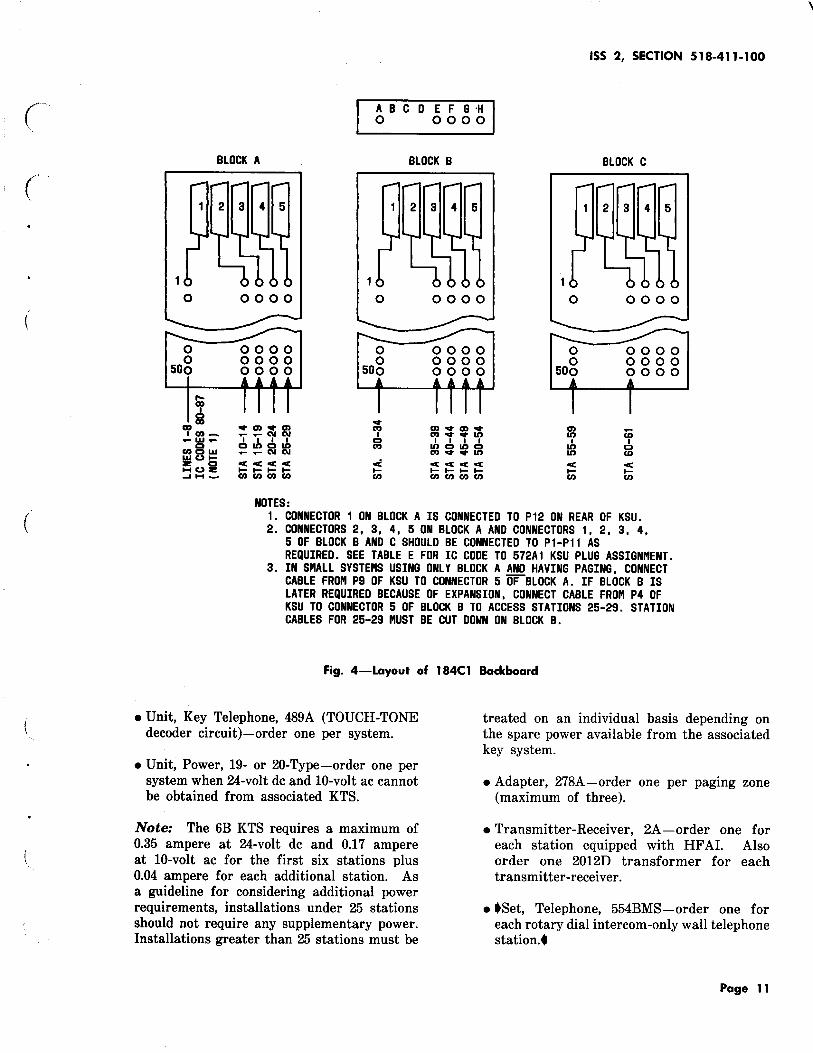
(COAM) or telephone company-provided amplifier and loudspeaker for paging. Up to three paging zones, plus one all-page zone, can be provided. When paging access is provided, the number of station codes is reduced by four since the 484A KTU in J16 becomes dedicated to paging. These leads appear in J9 on the rear of the KSU. Each paging zone (except all page) requires a 278A adapter as an interface between the 6B KTS and the amplifier (Fig. 11). A separate amplifier should be supplied for each zone. If desired, a separately supplied music source can be connected to the 278A adapter(s) as background music through the amplifiers to the paging speakers. If background music is connected, one 278A adapter must be strapped to present an 8-ohm load to the music source. The adapters must be separately mounted from the KSU and require -24 volts de and ground which must be supplied from a separate source.
ISS 2, SECTION 518-411-1 00
5.08 The codes assigned to paging addesss are 71, 72, and 73. If all page is desired, the
code is 70. When paging access is provided, station codes 50 through 53 are converted to use as 70 through 73 and, therefore, are not available as station codes. The conversion is accomplished by operating the toggle switch marked P AG ACC to the ON position. The switch is located on the rear of the 572Al KSU just above the connectors for the incoming cables. As factory provided, the switch is in the OFF position. The 484A KTU for codes 50 through 53 must be converted for the continuous ring option (option A). •cabling methods, when paging access is provided, are shown in Fig. 39 .•
5.09 Any 6B KTS station can make a paging call as follows:
(1) Paging station goes off-hook and dials 71, 72, 73 for desired paging zone or code 70
if all zones are to be paged.
(2) The 278A adapter associated with the zone(s) will disconnect the background music if
provided and connect the paging station to the amplifier. •A muted• alerting tone will be sent through the speakers and the paging station will hear acknowledgment tone.
(3) Paging station can now make announcement to speakers using telephone handset.
CO/PBX LINE ACCESS
5.10 All 6B KTS stations can access up to eight CO/PBX lines under the following conditions
only:
• While ringing is applied to the line
• If the line has been placed on hold through the associated key system line circuit.
Access cannot be made when the line is idle or in the talk mode; therefore, outgoing calls cannot be made through the 6B KTS. The CO/PBX line must be terminated in a lAl or 1A2 line circuit having A-lead control. The line circuit is required to determine whether the CO/PBX line is ringing, idle, busy, or on hold. Access to the lines in the proper state is made by dialing a 2-digit code. Once an incoming call has been answered and put
Page 35
SECTION 518-411·100
TO STATION CONNECTIONS CODES 51. 52 OR 53
TO COAPt [ AIFLIFIER
[
TO BACKGROUND [ IIJSIC SOURCE
TO OTHER [ 278A ADAPTERS
NOTES:
T
R
A
A1
BZ1
BZ
-248
8 GRD
-
278A ADAPTER
""T (NOTE 2}
""' -Q)R : :=J (NOTE 1} ....,. BV2 ~
1?. BV1 ~ Co
..nt. BZ1 XJ Do
1?. BZ2 --<.1 : :=J (NOTE 1)
"" CT XJ
-0 CR : :=J (NOTE 1) 0 -v
-Q)GRD Jo
0A Ko
0 C1
0C2
V"1 ,PI2
1. OPTION PLUGS IIJST BE POSITIONED IN E-F AND G-H ON ONE ADAPTER ONLY - LEAVE PLUGS STORED ON SECOND AND THIRD ADAPTER. POSITION PLUG IN A-B ON ALL ADAPTERS
2. ADD CONTINUOUS RING OPTION TO ASSOCIATED 484A KTU.
Fig. 11-278A Adapter Connections for Paging Access
on hold, the call can be transferred to another station or a station can be added on.
5.11 Incoming CO/PBX calls are handled by intercom stations as follows:
(1) When line is called, associated line circuit. will provide flash indication.
(2) Answering station accesses line by dialing a 2-digit CO/PBX access code (80 through 87)
assigned to line.
Page 36
(3) The answering station can then either:
(a) Handle the call and disconnect by going on-hook
(b) Pass the call to another intercom station by flashing the switchhook to place call
on hold, dialing the other station and, when they have answered, disconnecting
(c) Add another station by flashing the switchhook to place call on hold, dialing
the other station and, when they have answered,
(-
(
(
(
(
flashing a second time to reenter the original connection.
The previous procedure is for 6B KTS stations and does not prevent the CO/PBX line being picked up in a normal manner on key system sets if it appears.
ATTENDANT RECALL
5.12 To recall the attendant on a PBX call that is connected through the 6B KTS, the
answering station must flash the switchhook which will return intercom dial tone. The station then dials 00 which will send a timed flash to the PBX •line which will alert the PBX operator. This feature should not be used with PBX lines that return dial tone on a switchhook flash or on a CO line as it will result in a lost call• .
6. MAINTENANCE
6.01 Maintenance information pertaining specifically to the 6B KTS is provided in three forms:
• Feature sequence charts (Tables F through 0)
• Trouble analysis charts (Fig. 13 through 22)
• Diagnostic test sequences (Fig. 23 through 34).
A. Feature Sequence Charts
6.02 These charts provide a method of testing for the proper sequence of each feature.
No equipment failure indications are given.
B. Trouble Analysis Charts
6.03 This series of charts provide an analysis of the probable trouble causes depending on
the more likely trouble reports. Some results may require further testing using the Diagnostic Test Sequences.
ISS 2, SECTION 518-411-100
C. Diagnostic Test Sequences
6.04 These tests require the use of the optional HK-14 circuit pack (Fig. 12) and a 1013-type
hand test set. Maintenance operations involving the HK-14 circuit pack should be performed by 2nd-tier maintenance personnel only. Using the test sequences, the status of the major signaling busses and the system power for all links can be tested. Visual signals are provided on the circuit pack and audible tones heard in the hand test set.
6.05 The HK-14 circuit pack must be plugged into J6 in place of the first 484A KTU.
As soon as it is plugged in, the stations associated with the first 484A KTU will get a system busy indication, ie, the intercom lamp will light steadily at the stations. •connect hand test set in talk mode to terminals at bottom of HK-14 circuit pack .• When the ON switch is operated, all stations will see a system busy and the system will be taken out of service until the switch is turned off'.
6.06 To start the sequence after the switch is turned to ON, 05 must be dialed •on the
hand test set• . The circuit pack will then test each link for each test. For instance, after 05 is dialed, the digit 1 will be displayed and link 1 tested for dial tone, then link 2 and if provided, links 3 and 4. •The craftsperson must listen for dial tone as well as look at the "PASS" LED .• The test will then be repeated unless the STEP switch is depressed or the circuit pack turned off. If the STEP switch is depressed, the circuit pack will make the next test of each link in sequence. The test being made is displayed visually (Fig. 12). If it is desired to make a particular test, the circuit pack must be stepped until the proper digit or letter is displayed. Refer to Table P and Fig. 23 through 34 for the circuit pack preparation sequence and the individual test sequences.
6.07 The voltages used in the system are monitored continuously as soon as the circuit pack is
plugged in.
Page 37

SECTION 518-411 - 1 00
Page 38
0 CIRCUIT PACK ON SWITCH
TEST VISUAL DISPLAY
TEST STEP SWITCH
TERMINALS FOR HAND T ESTSET
Fig. 12-HK-14 Circuit Pack Faceplate

(
(
TABLE F
OVERRIDE (OVRD)
ISS 2, SECTION 518-411-100
At override station, depress IC button, go off-hook.
OK
IC dial tone.
IC dial tone.
OK
Override tone heard by conversing parties then override station enters call
or Override station hears audible ringback and called station in DND or idle mode is rung.
Dial 01. FAILURE
Error tone-1. Feature attempt by nonoverride station. 2. Invalid procedure, station must reattempt
feature activation.
Dial code of station to be overridden.
TABLE G
DO-NOT-DISTURB . (DND)
FAILURE
Error tone-1. Paging code dialed or called station paging. 2. Called station not a working station. 3. Called station on hold. 4. Called station link at maximum capacity.
At any station, depress IC button, go off-hook.
OK
IC dial tone.
Dial 06.
OK
\ '· Acknowledgment tone.
Calling stations receive busy tone. Lamp will flash at DND station but audible signal is silenced. Call can be answered or ignored.
Page 39

SECTION 5 '18-411-1 00
OK
IC dial tone.
OK
IC dial tone.
OK
IC dial tone.
OK
Audible ringback heard at calling station-audible signals heard at called station.
OK
Conference established.
Page 40
TABLE H
CONFERENCING (FLEX)
At any station, depress IC button, go off-hook.
Dial 03 ( 3-party conference) or 04 ( 4-party conference).
FAILURE
Error tone-Invalid procedure station must reattempt feature activation.
Dial code of 1st station to be conferenced.
FAILURE
Busy tone-Busy station dialed. Procedure terminated.
Dial code of 2nd (and 3rd) station to be conferenced. Dial tone returned after each code dialed.
Called stations go off-hook.
FAILURE
Error tone-Invalid code (otherthan 10 through 69) in conference call.
FAILURE
If HF AI station answers from adjunct it may be dropped-must go to handset.

{
(
IC dial tone.
IC dial tone.
Feature activated. Call answered.
OK
OK
OK
TABLE I
REMOTE ANSWER (REAN)
ISS 2, SECTION 518-411-100
At any station, depress IC button, go off-hook.
Dial 07. FAILURE
Error tone-Invalid procedure, station must reattempt feature activation.
Dial code of station to be answered.
FAILURE
Error tone-1. Nonstation code dialed. 2. Call already answered by remote station. 3. Attempt is to station which has activated
CFWD and alternate station has answered.
Page 41

SECTION 518-411-100
IC dial tone.
OK
IC dial tone.
OK
Acknowledgment tone.
OK
Flash dial tone.
OK
Timed flash (450 ms) to PBX operator.
Page 42
TABLE J
CALL FORWARDING (CFWD)
At any station, depress IC button, go off-hook.
Dial 02.
Dial code of alternate station.
FAILURE
Error tone-Automatic callback in effect. Busy tone-No memory available.
FAILURE
Error tone-
1. Alternate station not a working station. 2. Nonstation code.
Busy tone-Alternate station in DND.
Audible and lamp signals operate at both stations on calls to originating station. Calls can be answered at either station. Signals time-out at originating station after 12 seconds.
TABLE K
PBX OPERATOR RECALL
PBX call in progress. Station flashes switchhook.
Dial 00. FAILURE
Error tone-no PBX link available.
Operator answers or dial tone is returned if connected to a PBX/CTX line.
(

(
(
TABLE L
SUPERVISORY FLASH FEATURES (C HOLD, CADD, XFER)
ISS 2, SECTION 518-411-100
Connection established to another 6B station or CO/PBX line.
Flash dial tone-connection put on hold (C HOLD).
I Station flashes switchhook.
Third station dialed-answers.
~-----------------------<'>---------------~ y Third station goes on·hook. Originating station flashes.
I Original connection reestablished.
Originating station flashes.
I Original connection reestablished, third station added (CADD).
Originating station goes on-hook.
Third station connected to held station (XFER).
Page 43

SECTION 518-411-100
OK
Flash dial tone.
OK
IC dial tone.
OK
Acknowledgment tone.
Page 44
TABLE M
AUTOMATIC CALLBACK (ACBK)
Busy tone received when IC station is called. I
Flash switchhook.
Dial 09.
Dial code of busy station.
FAILURE
Error tone-1. ACBK already originated by station. 2. Invalid procedure-station must reattempt
feature activation. Busy tone-Memory unavailable.
FAILURE
Error tone-1. Code of nonworking station dialed. 2. Busy station is in DND. 3. Nonstation code dialed.
Audible ringback-Busy station became idle during feature activation. Call completed in normal manner.
When called station becomes idle, system will ring originating station then called station.
(
(

(
( OK
Reminder dial tone.
OK
Acknowledgment tone.
OK
IC dial tone.
OK
Connection established to CO/PBX line.
TABLE N
FEATURE CANCELLATION
DND, ACBK, or CFWD feature in effect.
I Originating station goes off-hook.
Originating station dials own station code.
DND, ACBK, and/or CFWD canceled.
TABLE 0
CO/PBX LINE ACCESS
Line button flashes, indicating incoming call. I
At any 6B station, depress IC button, go off-hook.
Dial code (80-87) assigned to CO/PBX line.
6B station can handle call, then go on-hook or
Transfer call by flashing (call goes on hold), calling another station, and going on-hook when answered
or Add station by flashing, calling another station, and flashing a second time when other station answers.
ISS 2, SECTION 518-411-100
FAILURE
CO/PBX line idle or busy.
Page 45/46


ISS 2, SECTION 518-411-100
IS ONLY YES REPLACE LAJIIP TROUBLE YES ONE STATION . AT AFFECTED CLEARED AFFECTED STATION
NO NO NO (
CHECK FOR 10 VAC ON LG LEAD ARE AFFECTED YES CHECK FUSE
STATIONS ON . IN FUSE ONE 484A KTU BOARD*
NO r IS 10 VAC NO CHECK ON LAMP ...... LG LEAD LEAD CHECK 10 VAC
WIRING. CHECK YES LAJIIP WIRING
CHECK L LEAD
~ ~
TROUBLE NO REPLACE ASSOCIATED * IF FUSE IS OPERATED, BOTH LA CLEARED 484A KTU AND BUZZER WILL BE AFFECTED.
PIPS
YES
Fig. 13-lntercom Lamp Does Not Light
Page 47

SECTION 518-411-100
IS SIDE TONE PRESENT
NO
TO SHEET 2
Page 48
IS ONLY ONE STATION AFFECTED
NO
ARE AFFECTED STATIONS ON ONE 484A KTU
NO
REPLACE 48GA KTU
YES REPLACE ASSOCIATED 484A KTU
TROUBLE CLEARED
YES
Fig. 14-No Dial Tone (Sheet 1 of 2)
NO
TROUBLE CLEARED
NO
REPLACE 485A KTU
TROUBLE CLEARED
NO
PERFORM DIAGNOSTICS TEST NO. 1
("
(
YES
YES

(.
(
FROPI SHEET 1
NO
NO
REPLACE 48GA KTU
YES
REPLACE ASSOCIATED 484A KTU
TROUBLE CLEARED
NO
PERFORM DIAGNOSTICS TEST NO. 1
YES
TROUBLE CLEARED
NO
DOES INTERCOM LAMP LIGHT
NO
CHECK FOR FAULTY A LEAD CONNECTIONS
Fig. 14-No Dial Tone (Sheet 2 of 2)
ISS 2, SECTION 518-411-100
YES
CHECK FOR FAULTY T AND R CONNECTIONS
Page 49

l ca I'll
U'l 0
IS ONLY YES ONE STATION AFFECTED
NO
REPLACE 485A KTU
CHECK FOR FAULTY TROUBLE YES T AND R -- CLEARED WIRING
NO
TROUBLE YES REPLACE CLEARED ASSOCIATED
484A KTU
NO
CHECK FOR LINK TROUBLE YES
CROSSTALK .. CLEARED
NO
, PERFOR" DIAGNOSTICS TEST NO. 1
Fig. 15-lk:Cmnot Dial From Rotary Dial Telephone Se ..
REPLACE TELEPHONE SET
1\
NO
' TROUBLE YES .. CLEARED
............. , .... ')
U'l
-~ 0 z U'l -t --I -0 0

'l CD
CD
Ul -
IS ONLY YES .. ONE STATION . AFFECTED
NO
REPLACE 489A KTU ..
CHECK FOR FAULTY .. TROUBLE YES T AND R CLEARED WIRING
NO
TROUBLE YES REPLACE
CLEARED ASSOCIATED 484A KTU
NO
'
REPLACE TROUBLE YES 488A KTU -- CLEARED
NO
1
REPLACE 485A KTU
Fig. 16-.Cannot Dial From TOUCH.JONE Telephone Set.
REPLACE TELEPHONE SET
NO
TROUBLE CLEARED
TROUBLE .. CLEARED
NO
PERFORM DIAGNOSTICS TEST NO. 1
--- ---.,_
YES
YES
~ ~11.:1
"' p; -1
0 z Ul -00 .1. --I -8

SECTION 518-411-100
DOES IC LMP LIGHT AT AFFECTED STATION
NO
ARE AFFECTED STATIONS ON ONE 484A KTU
Page 52
NO
ARE ALL STATIONS AFFECTED
NO
CHECK OPTION PLUGS ON ASSOCIATED 484A KTU
CHECK FUSE ON FUSE BOARD
REPLACE 48SA KTU
NO
REPLACE BUZZER
TROUBLE CLEARED
TROUBLE CLEARED
NO
CHECK FOR FAULTY BZ, BZ1 I OR B LEAD WIRING
Fig. 17-lntercom Buzzer Does Not Operate
YES
NO
YES
REPLACE ASSOCIATED 484A KTU
r·
(

( IS DIAL TONE PRESENT
( NO
SEE PROCEDURE FOR NO DIAL TONE
CHECK OPTION PLUGS ON 488A KTU
TROUBLE CLEARED
NO
REPLACE 488A KTU
TROUBLE CLEARED
NO
REPLACE 485A KTU
YES
YES
Fig. 18-No Audible Ringback
ISS 2, SECTION 518-411-100
TROUBLE CLEARED
NO
PERFIJRIII DIAGNOSTICS TEST NO. 2
YES
Page 53
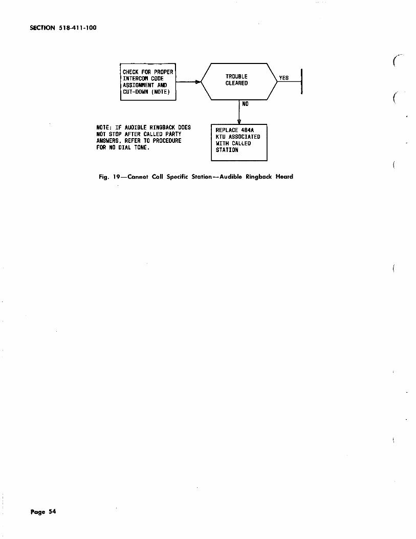
SECTION 518-411-100
CHECK FOR PROPER INTERCOPI CODE ASSIGNPIENT AND CUT-DOWN (NOTE)
NOTE: IF AUDIBLE RINGBACK DOES NOT STOP AFTER CALLED PARTY ANSWERS, REFER TO PROCEDURE FOR NO DIAL TONE.
TROUBLE CLEARED
NO
REPLACE 484A KTU ASSOCIATED WITH CALLED STATION
YES
Fig. 19-Cannot Call Specific Station-Audible Ringback Heard
Page 54
(

{
(
(
ARE ALL STATIONS AFFECTED
NO
GROUND H LEAD AT AFFECTED STATION. PUT CALL ON HOLD
DOES CALL GO ON HOLD
NO
CHECK FOR FAULTY H LEAD WIRING
YES
YES
REPLACE 488A KTU*
CHECK WIRING OF HOLD KEY
TROUBLE CLEARED
NO
REPLACE ASSOCIATED 484A KTU
YES
ISS 2, SECTION 518-411-100
TROUBLE YES CLEARED
NO
PERFORf'l DIAGNOSTICS TEST NO. 8
*CALLS PlAY BE GOING ON HOLD BUT LAf'IP WINK FUNCTION IS NOT OPERATING. REPLACE 488A KTU.
Fig. 20-Cannot Place Intercom Call On Hold
Page 55

SECTION 518-411-100
BUSY TONE HEARD WITH LINE BEING RUNG DR ON HOLD
LINE DROPPED DR GOES INTO HOLD WHEN ACCESSED
Page 56
REPLACE ASSOCIATED 488A KTU
CHECK WIRING 1-----EIII OPTIONS
TABLE D
TROUBLE CLEARED
CHECK FOR FAULTY A AND/OR L CONNECTIONS
TROUBLE CLEARED
YES
CHECK FOR PROPER LINE ACCESS CODE ASSIGNPIENT
TROUBLE CLEARED
Fig. 21-~nnot Access CO/PBX Line in Ringing State or On Hold.
REPLACE ASSOCIATED 488A KTU
TROUBLE CLEARED
NO
CHECK FOR FAULTY A LEAD
YES
Fig. 22-Cannot Release From Answered CO/PBX Line
CHECK FOR OPEN T AND R CONNECTIONS
(
( \

ISS 2, SECTION S 18-411-l 00
REMOVE FIRST CONNECT HAND 484A KTU FROM
~ TEST SET TO JB TERMINALS
(
PLUG HK-14 TURN SWITCH INTO JB TO ON
(
ALL VOLTAGE NO CHECK FUSING LINK LAMP NO SYSTEM PlAY BE SUPPLY LAMPS AND POWER ON BUSY- IF NOT, ON CONNECTIONS REPLACE 48BA KTU
YES YES
RTC LAPIP NO REPLACE 48BA KTU, ON 485A KTU OR
POWER SUPPLY DIAL 05
( YES
r
SCN LAMP NO REPLACE ON 485A KTU DIGIT 1 SHOWS TURN BOARD OFF.
NO RECHECK STATUS ON VISUAL ~ LAMPS. RESTART YES DISPLAY PROCEDURE.
YES 1" REPIOVE 484A AND
A LAMP NO 488A KTUs ONE AT A TIME UNTIL LAPIP ON LIGHTS. REPLACE DEFECTIVE KTU READY FOR
YES TESTS
Fig. 23-HK-14 Diagnostic Circuit Pack Preparation
Page 57

SECTION 518-411-100
DIGIT 1 SHOWS NO SEE FIGURE FOR LINK 3 NO REPLACE 486A ON VISUAL CIRCUIT PACK LAMP ON KTU OR SECOND DISPLAY PREPARATION 487A KTU
YES YES (
NO REPLACE 486A PASS NO REPLACE LINK 1 KTU OR FIRST LAMP ON SECOND LAMP ON 487A KTU 487A KTU
YES YES REPLACE 486A KTU OR SECOND 487A KTU.
PASS NO REPLACE DIAL TONE NO REMOVE 484A AND _.. LAMP ON FIRST HEARD 488A KTUs ONE AT 487A KTU TIME UNTIL DIAL
YES YES TONE IS HEARD.
REPLACE 486A KTU OR FIRST 487A KTU.
DIAL TONE NO REMOVE 484A AND REPLACE 486A HEARD ~ 488A KTUs ONE AT LINK 4 NO KTU OR SECOND TIME UNTIL DIAL LAMP ON 487A KTU
YES TONE IS HEARD. YES
NO REPLACE 486A PASS NO REPLACE LINK 2 KTU OR FIRST LAMP ON SECOND LAMP ON 487A KTU 487A KTU
YES YES REPLACE 486A KTU OR SECOND 487A KTU.
PASS NO REPLACE DIAL TONE NO REMOVE 484A AND LAMP ON FIRST HEARD 488A KTUs ONE AT 487A KTU TIPIE UNTIL DIAL
YES YES TONE IS HEARD.
REPLACE 486A KTU OR FIRST 487A KTU.
DIAL TONE NO REMOVE 484A AND HEARD 488A KTUs ONE AT
TIME UNTIL DIAL YES TONE IS HEARD.
IS SYSTEM YES EQUIPPED WITH TWO 487A KTUs
NO END OF TEST 1
Fig. 24-Test I Sequence-Link Operation and Dial tone
Page 58

ISS 2, SECTION 518-411-100
LINK 2 NO SEE ( LAMP ON TEST 1
NOTE: IF SYSTEM IS EQUIPPED YES WITH SINGLE SPURT AUDIBLE RINGBACK OPTION, THE AUDIBLE RINGBACK TONE WILL BE
AUDIBLE NO REPLACE CONTINUOUS FOR THE TEST. RING BACK .. 485A OR HEARD. 48SA KTU
YES
~
IS SYSTEM YES EQUIPPED WITH
\, TWO 487A KTUs
NO
END OF TEST 2
Fig. 25-Test 2 Sequence-Audible Ringback
Page 59

SECTION 518-411-100
DEPRESS STEP
LINK 3 ND SEE
SWITCH LAJIIP ON - TEST 1
YES
, (
DIGIT 3 SHOWS IF 2 IS DISPLAYED
ND DEPRESS SWITCH BUSY TONE NO REPLACE
ON VISUAL - AGAIN. IF 2 STILL HEARD - 485A OR
DISPLAY DISPLAYED, START 488A KTU
FROM PREPARATION YES YES
,, , LINK 1 NO SEE
LINK 4 NO SEE LAMP ON -- TEST 1 (
LAMP ON -... TEST 1 YES
YES , BUSY TONE NO REPLACE BUSY TONE NO REPLACE
HEARD 485A OR HEARD - 485A OR ....... 488A KTU
488A KTU YES
YES
LINK 2 NO SEE LAI"'P ON -- TEST 1
YES
BUSY TONE NO REPLACE HEARD -- 485A OR
488A KTU
YES
IS SYSTEM YES EQUIPPED WITH TWO 487A KTUs
ND , END OF
"' TEST 3
Fig. 26-Test 3 Sequence-Busy Tone
Page 60

ISS 2, SECTION 518-411-1 00
DEPRESS STEP LINK 3 NO SEE
SWITCH ....... LAMP ON TEST 1
YES
( , , IF 3 IS DISPLAYED
DIGIT 4 SHOWS NO DEPRESS SWITCH ERROR TONE NO REPLACE
ON VISUAL --,.. AGAIN. IF 3 STill HEARD 485A OR DISPLAY DISPLAYED, START 488A KTU
FROM PREPARATION YES YES --, ,
LINK 1 NO SEE LINK 4 NO - SEE
LAMP ON TEST 1 LAMP ON TEST 1 (
YES YES
, , ERROR TONE NO REPLACE ERROR TONE NO REPLACE
485A OR HEARD 485A OR HEARD -.. 488A KTU
488A KTU
YES YES
~
, '_,
LINK 2 NO SEE LAMP ON TEST 1
YES
,lr
ERROR TONE NO REPLACE HEARD 485A OR
488A KTU
YES l-.
IS SYSTEM YES EQUIPPED WITH TWO 487A KTUs
NO ,
~ END OF ""' TEST 4
Fig. 27-Test 4 Sequence-Error Tone
Page 61

SECTION 518-411-1 00
Page 62
DEPRESS STEP SWITCH
YES
DISPLAY TURNS ON AND OFF AT FLASH RATE
YES
END OF TEST 8
DEPRESS STEP SWITCH
IF 4 IS DISPLAYED DIGIT 5 SHOWS NO DEPRESS SWITCH ON VISUAL AGAIN. IF 4 STILL DISPLAY DISPLAYED, START
FRO" PREPARATION. YES
lr
TEST 5 NOT PRESENTLY USED. PROCEED TO NEXT TEST.
Fig. 28-Test 5 Sequence
DISPLAY BLANK
YES
REPLACE 485A OR 488A KTU OR RE"OVE 484A
>-NO _ _.. KTUs ONE AT A TI"E UNTIL DISPLAY FLASHES. REPLACE DEFECTIVE KTU.
NO
Fig. 29-Test 6 Sequence-Flash Rate
IF 5 IS DISPLAYED DEPRESS SWITCH AGAIN. IF 5 STILL DISPLAYED, START FRO" PREPARATION.
(

(
(
DEPRESS STEP SWITCH
YES
YES
END OF TEST 7
DISPLAY BLANK
YES
REPLACE 485A OR 48BA KTU OR RE~VE 484A KTUs ONE AT A TIRE
~-.....,UNTIL DISPLAY SHOWS RING RATE. REPLACE DEFECTIVE KTU.
Fig. 30-Test 7 Sequence-Ring Rate
ISS2,SECTION 518-411-100
IF 6 IS DISPLAYED DEPRESS SWITCH AGAIN. IF B STILL DISPLAYED, START FRO" PREPARATION.
Page 63

SECTION 518-411-100
Page 64
DEPRESS STEP SWITCH
YES
YES
END OF TEST 8
NO
DISPLAY BLANK
YES
REPLACE 485A DR 488A KTU DR RE"OVE 484A KTUs ONE AT A TIME
>--...... UNTIL DISPLAY WINKS. REPLACE DEFECTIVE KTU.
Fig. 31-Test 8 Sequence-Wink Rate
IF 7 IS DISPLAYED DEPRESS SWITCH AGAIN. IF 7 STILL DISPLAYED, START FRO" PREPARATION.
(

ISS 2, SECTION 518-411-100
( DEPRESS STEP SWITCH
( IF 8 IS DISPLAYED
DIGIT 9 SHOWS NO DISPLAY NO DEPRESS SWITCH ON VISUAL .. __., AGAIN. IF 8 STILL DISPLAY BLANK DISPLAYED, START
FROM PREPARATION. YES YES
( REPLACE 486A KTU
END OF OR REMOVE 488A TEST 9 KTUs ONE AT A TIME
UNTIL DISPLAY SHOWS 9. REPLACE DEFECTIVE KTU.
Fig. 32-Test 9 Sequence-Slow CO Disconnect
DEPRESS STEP SWITCH
IF 9 IS DISPLAYED LETTER A SHOWS ON NO DISPLAY NO DEPRESS SWITCH
__., AGAIN. IF 9 STILL VISUAL BLANK DISPLAYED, START DISPLAY FROM PREPARATION YES YES
REPLACE 486A KTU END OF DR REMOVE 488A TEST A KTUs ONE AT A TIME
UNTIL DISPLAY SHOWS A. REPLACE DEFECTIVE KTU.
Fig. 33-Test A Sequence-Fast CO Disconnect
Page 65

SECTION 518-411-100
Page 66
DEPRESS STEP SWITCH
LETTER b SHOWS ON VISUAL DISPLAY
YES
DISPLAY TURNS ON AND OFF ABOUT 8 TIPIES
YES
END OF TEST b
NO
DISPLAY BLANK
YES
REPLACE 485A OR 486A KTU OR REMOVE 484A KTUs ONE AT
r--~ A TIME UNTIL DISPLAY SHOWS b. REPLACE DEFECTIVE KTU.
Fig. 34-Test 8 Sequence-Alert Time-Out
IF A IS DISPLAYED DEPRESS SWITCH AGAIN. IF A STILL DISPLAYED, START FROM PREPARATION.
c·

(
{
ISS 2, SECTION 518-411-100
CIRCUIT PACK HK-14 LAMP INDICATIONS AND SWITCHES
LAMP OR SWITCH FUNCTION
1
2
3 Indicates which link is being tested
4
PASS
FAIL Indicates the outcome of a test
A When lit, indicates proper operation of the A lead buss
Status Lamps ATLL When lit, indicates ATLL buss is operating properly
RTC When lit, indicates proper operation of Real Time Clock
SCN When lit, indicates processor is scanning stations
+7V
-lOV
+lOV When lit, indicates presence of proper voltage in system
-24V
-5V
1 Link operation and dial tone
2 Audible ringback
3 Busy tone
4 Error tone
5 Automatic transfer function*
LED Display 6 Flash rate Lamp 7 Ring rate
8 Wink rate
9 Slow CO disconnect
A Fast CO disconnect
B Check for Alert Time Out
ON In the ON position, provides off-hook indication to the system
Switch STEP Steps the Diagnostic Test program through the steps
ATXFR Used with test number 5*
*When making this test, FAIL lamp is normally lit. When ATXFR switch is depressed, PASS lamp lights. Test 5 is presently not used with 6B KTS.
Page 67/68

/
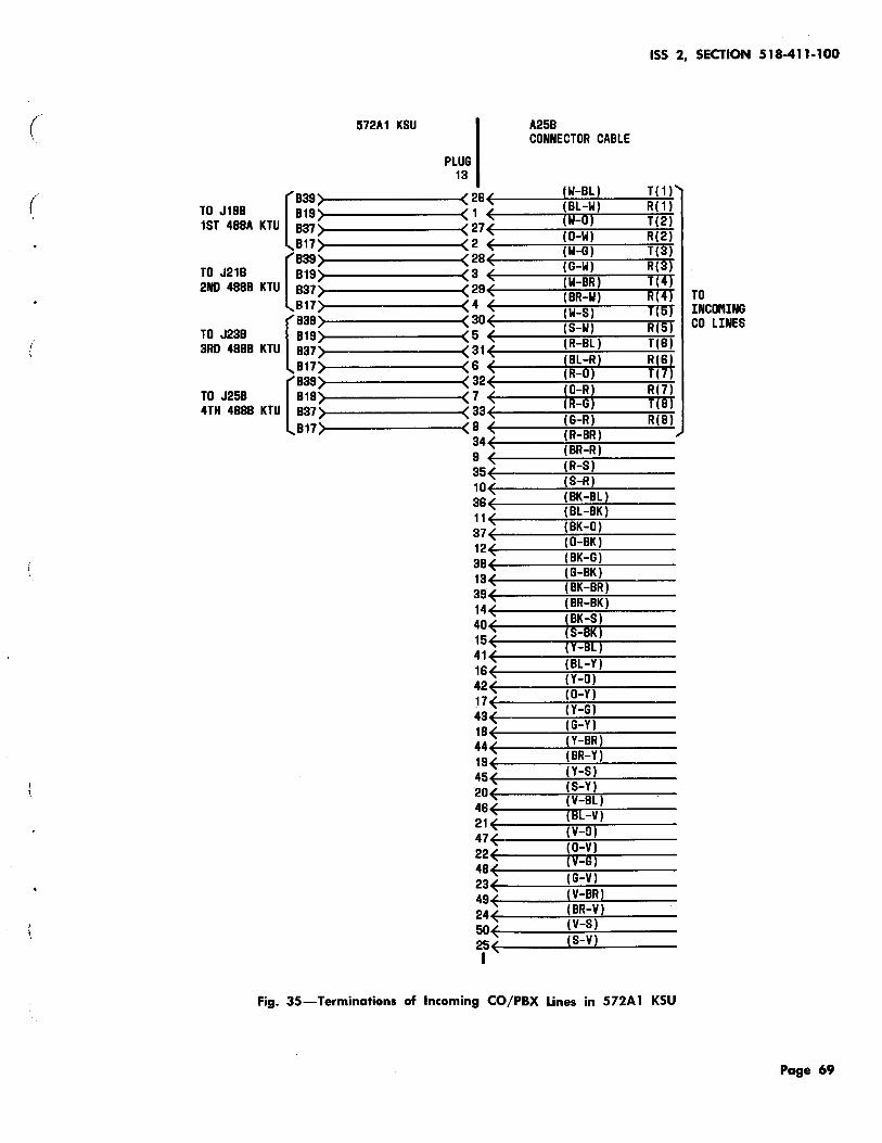
(
( [
839 TO J198 819 1ST 488A KTU 837
817
[
839 TO J21B 819 2ND 4888 KTU 837
817
[
839 TO J23B 819 3RO 4888 KTU 837
817
[
839 TO J25B 819 4TH 4888 KTU 837
817
572A1 KSU
.... , ,
ISS 2, SECTION 518-411-100
A258 CONNECTOR CABLE
PLUG 13
....
26 E ( W-BL ) T ( 1 ) 1 ( (BL-W) R(1)
27 < tw-O) T(2J 2 ( (0-W) R(2) 28 E (W-G) 1(3) 3 ( (G-W) R(3)
29 ( (W-BR) T(4) (BR-W) R(4) TO
4 ~(----:(~W~-S~).:__ _ __;,;.f.;.,;(S;..;.) INCOPIING 30 ( (S-W) R(5) CO LINES 5 ~(---...;.:...~,.....---....;;.;.;+ 31 ( (R-BL) T(6) 6 E (BL-R) R(6)
32 ( (R-0) T(7) 7 ( (0-R) R(7)
33 ( (R-G) T(8) 8 E (G-R) R(8) 34~(----:(~R~-B~R~) ___ _ 9 ~E----:(~B~R-,:.;.R.!...) ----35~(---~(=::-R--=S~) ----10~(---..\(;,.S-.;.:.R~) ..,....----36~(---~(~BK~-~B~L)~----11 ~(----~(~B~L-~BK~)~---37~(----~(~BK~-~0~)-----12~(-----:(~0-~B~K~) ___ _ 38~(---~~~B~K-~G~) ___ _ 13 ~ (G-BK) ~,---~~~B~K-~B~R)~----
39~(---~~~B=::-R--=B~K)~---14~(---~(~B~K-..;S~) ~---40~(----~(S~-~BK~)~----15~(-----~(Y~-~BL~)-----41~(----~~B~L~-Y~)-----16~(----+(Y~-~0~)----42~(----~~------17~(---..;(::-0--:i:-Y~) ----43~(----~(.:-Y-~G~) ----18 (G-Y) ~(----~(::-Y-~BR~)----
44~E-----~(=BR~-Y~)~----19~(----..\(::;:.Y-~S.:...l) ~---45~(------~(~S-~Y.!...)-----20~(----~(~V-~B~Ll,.....-----46~(---~(~Blr-~yr)----21~(----:,mv-~o~J.:.__ __ __ 47~(-----:(~0-~V~)-----22~(----:(~V~-Gri)-----48~(----~,G~-~v~,----23~(-----~....::=-:,.....-----49~(---~~~V~-B~R~) ___ _ 24~(-----~(B~R~-V~) ___ _ 50~(-----~~v~-~s~) ___ _ ~~(----~(S~-~VL) ___ _
Fig. 35-Terminations of Incoming CO/PBX Lines in 572A 1 KSU
Page 69

SECTION 518-411-100
572A1 KSU A25B 184C1 BACKBOARD ( CONNECTOR CABLE
PLUG I BLOCK A 12 COLUMN A
28E (W-BL) ~28
1 ( (BL-W) 1 E (W-liJ ) 1 ) 0
A( 1) 811 27E (O-W) ) 27) 0
831 2 E (W-G) ) 2 ) a5 TO J198 28 E (G-W) )28) a
L(1) 1ST 488A KTU 814 s E [lii-BRJ ~3 ) a
29E (8R-W) )29 4 E llii-SJ )4 ) 0
A(2) 812 SOE (S-W) ) SO) 0 10 8S2 s E (R-8L) )5
s1 E ) S1) a I 815 8 E IBL-RI ) 6 ) 0
L(2)
32E (R-D) ) S2
7 E !O-R~ ) 7 ) 0 15 811 SSE (R-G) ) 3S) A(S) (G-R)
0
831 a E (R-8R) )8 TO J21B S4E (BR-R) )34) 0
L(S) 2ND 488A KTU 814 9 E (R-S) )9 ) 0
SSE (S-R) ) 35) 0
20 10 E (8K-8L) ) 10) 0 A(4) 812 36E ) S8) (I)
(8L-8K) 0 1-.....
832 11 E ) 11 ;::, (BK-0) u
S7E ) S7) 0 a: (0-8K) L(4) .....
815 12 E ) 12) u (8K-G) 0 25 w
SSE ) sa z (G-8K) .....
1s E ) 1S) 0 ..... 811 SSE (8K-8R) ) S9) A(5) (I)
(BR-BK) 0 1-
8S1 14 E ) 14 :...:
(BK-S) TO J2SB 40E (S-BK) ) 40) 0 30 L(5) 3RD 488A KTU 814 15E (Y-I!I[J ) 15) 0
41 E (8L-Y) ~ 41 16 E (Y-O)
) 16) 0 A(6) B12 42E (0-Y) ) 42) 0
BS2 11E (Y-G) ) 17) 0
S5 4SE (G-Y) ) 4S) 0 L(6) 815 18E (Y-BRJ ) 18) 0
44E (BR-Y) ) 44
19 E (Y-S) ) 19) 0 A(7) 811 45E (S-Y) ) 45) 0
40 8S1 20E (V-BL) ) 20) 0
TO J258 48E 11!1[-llJ ) 46) 0 L(7) 4TH 488A KTU 814 21E (V-0) ) 21) 0
47E (0-V) ) 47
22E (V-G) ) 22) 0 45 A(S) 812 4BE (G-V) ) 48) 0
8S2 23E (V-BR) ~ 2S 49E (BR-V) ) 49) 0 L(B) B15 24E (V-S) ) 24) 0
50E (S-V) ) 50) 0 50 25( ) 25 I
Fig. 36-tconnections Between Plugs 12 and 1 to 4 of 572Al Key Service Unit and 184C1 Backboard (Sheet 1 of 5).
Page 70

TO FUSE 1
1ST 48 TO J68 4A KTU
TO J78 2ND 48 48 KTU
TO FUSE 2
"'86 826 87
828'" ,,
827, 88 ' , 89 80 812 832' a31~ ,,
810' .,
811' 830~ 829' ., 820 813 833 814
835'" ,,
834' 815~ -, 818 82 819 839 838
817' ,,
818 837 836 822
>as 827 87 ' ,
828" ,,
827' 88 ~ , 89 '" (
.... 80 ,
P1 I 26(
572A1 KSU
1 ( 27( 2 ( 28( 3 ( 29(
/
; '
4 ( 30( 5 ( 31 ( 6 ( 32 ( 7 ( 33( 8 ( 34( 9 (
' 35( 10 ( 38( 11 ( 37( 12( 38( 13( 39(
) '
14( 40( 15( 41 ( 16 ( 42( 17 (
/
' 43(
' 18( 44( 19 ( 45( 20( 46(
;
'
21 ( 47( 22( 48( 23( 49( 24 ( 50( 25( I
ISS 2, SECTION 518-411-100
A25B 184C1 BACKBOARD CONNECTOR CABLE (SEE TABLE E)
BLOCK A COLUMN E
(W-BL) )28) 1 T (8L-W)
0 ) 1 ) R
fii-!H 0 A (O-W) )27) 0 A1 (W-G) )2 ) 05 L TO (G-W) )28) 0
LG STATION 10 (lii-BRI )3 ) 0
H (BR-W) )29) a
B (11-SJ )4 ) 0
8Z (S-W) )30) 010 8Z1 {R-8L)
)5 ) 0 T (8L-R~
)31) 0 R (R-0) )6 > 0 A (O-R)
)32) 0 A1 )7 ) (R-G) ) 33) 015 L TO
(G-R) a LG STATION 11
(R-8R) )8 ) a
H (8R-R) )34) a 8 (R-~j )9 ) a 8Z (S-R)
)35) 020 BZ1
(8K-BL) ) 10) 0 T (8L-8K) )36) 0 R (BK-0)
) 11) a A (0-BK)
)37) 0 ~1
(8K-G) ) 12) a25 L )38) TO
(G-8K) 0 LG ) 13) STATION 12
(8K-8R) a
H OR 62 (BR-8K) )39) 0 B (BK-S) ) 14) 0 BZ (S-8K) )40) 0 30 BZ1 (Y-8Lj ) 15) 0 T (BL-Y)
)41) 0 R (Y-O)
) 18) a A (0-Y)
)42) 0 ~~
(Y-G) ) 17) 035 L )43) TO
(G-Y) 0 LG
U-BRJ ) 18) 0 STATION 13
)44) H OR 63 (8R-Y)
0 8 (Y-S) ) 19) a BZ (S-Y)
)45) 040 8Z1
(V-8L) )20) a T (B[-Vj )46) a R (V-0)
) 21) a A (0-V)
)47) 0 A1 (V-G) )22) 0 45 L (G-V)
)48) 0 LG TO
)23) 0 STATION 14 (V-BR) )49)
H OR 64 (8R-V) 0 B (V-§j )24 > 0 8Z (S-V) )50) 0 50 8Z1
)25) 0
Fig. 36-~nnections Between Plugs 12 and 1 to 4 of 572A 1 Key Service Unit and 184C1 Backboard (Sheet
2 of 5).
Page 71

SECTION 518-411-100
TO FUSE 2
TO J7B 2ND 48 4A KTU
TO FUSE 3
3RD 48 TO J8B 4A KTU
,. 812 832 831
810' .,
811'" sao' B29 B20 813 B33 B14
835' .,
B34' B1S( ., B16, 82 819 839 B38
B17' ,
818' B3-i~ 836
>B22 86 826, 87 ' ,
B28' .,
B27' 88 ( B9 ( BO ( , 812 B32 B31
B10,
B11' 830~ B29 B20
572A1 KSU
P2 I 26E 1 E 21 E 2 E 28E 3 E 29E 4 E 30 E 5 E 31 E 6 E 32 E 7 E 33 E 8 E 34E 9 E 35E 10 E 36 E 11 E 37E 12E
~
) ...
38E 13 E 39E 14 E 4DE 15 E 41 E 1BE
" 42E 11E 43E 18E 44E 19 E 45 (
J
' 2DE
; ;
<
46E 21 ( 47 E 22E
' 48 (
_) ~ ~ ; "
23E 49E 24( 5DE 25E I
A25B 184C1 BACKBOARD CONNECTOR CABLE (SEE TABLE E)
BLOCK A COLUP'IN F
(W-BL) ) 26) D1 T (8L-W) R lA-D) ) 1 ) D A (O-W) ) 27) D A1 (W-G) ) 2 ) D5 L TO (G-W) ) 28) D LG STATION 15 IA-BRJ ) 3 ) D
H OR 65 (BR-W) ) 29) D
B (A-S I ) 4 ) D
BZ (S-W) ) 30) 0 10 BZ1 (R-BL)
) 5 ) D T ) 31) D R (BL-RI ) 6 ) D
(R-0) ) 32) A !O-R)
D A1 ) 7 ) (R-G) ) 33)
0 15 L TO (G-R)
D LG STATION 16 (R-BR)
) 8 ) D H OR 66
(BR-R) ) 34) D B (R-S) ) 9 ) D BZ (S-R)
) 35) 020 BZ1
(BK-BL) ) 10) D T (BL-BK)
) 36) D R (BK-0)
) 11) D A (0-BK)
) 37) D A1
(BK-G) ) 12) 0 25 L TO (G-BK)
) 38) D L~
) 13) STATION 17 (8K-BR)
D H DR 67
(BR-BK) ) 39) D B
(BK-S) ) 14) D BZ (S-BK) ) 40) 0 30 BZ1 (Y-BL) ) 15) D 'I' (BL-Y)
) 41) D R (Y-O)
) 16) D A (0-Y)
) 42) D A1
(Y-G) ) 17) 0 35 L ) 43) D TO
(G-Y) LG STATION 18 ) 18) D (Y-BR) ) 44) H OR 68 (BR-Y)
D B (Y-S) ) 19) D BZ (S-Y)
) 45) D 40 BZ1 ) 20) 0 (V-BL) ) 46) T (BL-V) D R (V-0) ) 21) D A (0-V)
) 47) D A1
(V-G) ) 22) 0 45 L ) 48) D LG
TO (G-V) )23) 0 STATION 19 (V-BR) H DR 89 (BR-V) ) 49) D B (11-SI ) 24) D BZ (S-V) ) 50) 0 50 BZ1
) 25) a
Fig. 36-tConnections Between Plugs 12 and 1 to 4 of 572A 1 Key Service Unit and 184C1 Backboard (Sheet 3 of 5).
Page 72
( ..
..
(

(
(
TO FUSE 3
TO J88 3RD 48 4A KTU
4TH 48
TO FUSE 4
TO J9B 4A KTU
572A1 KSU
~"'813
833 814
835' .,
834'-., 815 B18 82 819 839 ass' .,
817'-,
818 837 838
>822 88 ' 828( 87 "( ,
828' ,
827 88 89 80 812' ss2~ ., 831' .,
810' .,
811 830 839 820' 81:3" B33 814
835' .,
834, B15' B1S( B2 ~ .... ,
A25B CONNECTOR CABLE
(W-BL) )28 > (BL-W) P3 28~(------~~~--~ 1 ~(-------m~~--~ 27~(------~~----~
2 ~(------~~----~ 28~(------~~~--~ 3 ~(-------m-.w.;....----4 29~(-----~,...-.,.;---4
4 ~(-------m~~--~ 30~(------~~----~ 5 ~(------~~~--~ 31~(------~~~--~
8 ~(------+:-=~:-....-4 32~(------~~~--~
7 ~(------~~----~ 33~(------~~----~
8 ~<------~~~--~ 34~(------~~~--~
9 ~(------~~~--~ 35~(------~~-----4
10~(------~~~---4
~~(------~~~---4 11 ~(------~::;....;.~---4 37~(------~~~--~ 12~(--------T;:;;~t----~
38~(------~~~---4
13~(--------+:::-~:-:----~
39~(------~~~--~
14~(------~~~---4
40~(------~~~--~ 15~(------....;-.:....,..,.+---~
41~(------~~~--~
18~(------~~...!...---~
42~(------~~----~ 17~(-------:-::~----~
43~(------~~~--~
18 ~(-------+.ir-7::0...---~ 44~(------~~~--~ 19~(------.....;..n;,.....~---4
45~(------~~~--~
20~(------~~----~ 48~(------~r7.r---~ 21~(------~~~--~
47~(------~:--:-:-:~--~ 22~(-------rn~----~ 48~(---~..,..;----+ 23~(---..;.;:;....~---+
49~(---~r:-m--~ 24~(----TtT-;,n...:.--~ 60~(------~~~--~ 25~(---~~---+
(w-0) ) 1 )
(0-W) )27)
(W-G) )2 )
(G-W) )28)
(W-BR) )3 )
(BR-W) )29)
lw-SJ )4 )
(S-W) )30)
(R-BL) )5 ) )31)
(BL-:Rl )8 ) (R-0) )32) (0-R) (R-G) )7 )
(G-R) )33)
(R-BR) )8 )
(BR-R) )34)
(A-S) )9 )
(S-R) )35)
(BK-BL) ) 10)
(BL-BK) )38)
(BK-0) ) 11)
(0-BK) )37)
(BK-G) ) 12)
(G-BK) )38) ) 13)
(8K-BR) (BR-BK) )39)
(BK-S) ) 14)
(S-BK) )40)
(Y-BL) ) 15)
(SL-Y) ) 41)
(Y-O) ) 18)
(0-Y) )42)
(Y-G) ) 17) )43)
(G-Y) ) 18) (Y-BR) (BR-Y)
)44)
(Y-S) ) 19)
(S-Y) )45)
(V-BL) )20)
(BL-V) )48)
(V-0) )21)
(0-V) )47)
(V-G) )22) )48)
(G-V) )23) (V-BR) (BR-V) )49)
tv-s) )24)
(S-V) )50) )25)
" ~ ~ '
~ '
_, ~ ...
J
~ ~ ...
" ) ) )
<
_,
~ ~ ' I
ISS 2, SECTION 518-411-100
184C1 BACKBOARD (SEE TABLE E)
BLOCK A COLUMN G
1 T a R a A a A1
a5 L TO a LG STATION 20 a
H a B a BZ a10 8Z1 a T a R a A a A1 a15 L TO a LG STATION 21 a H a B a BZ a20 BZ1 a T a R a A a A1 a25 L TO a LG STATION 22 0 H a B a BZ a30 BZ1 a T 0 R a A a A1 a35 L a TO
LG STATION 23 a H a B
0 BZ a40 BZ1 a T 0 R a A a A1 a45 L a LG
TO STATION 24 a H
0 B 0 BZ a 50 BZ1 0
Fig. 36-tconnections Between Plugs 12 and 1 to 4 of 572A1 Key Service Unit and 184C1 Backboard (Sheet
4 of 5).
Page 73/74

(

(
T 4TH 48
0 J98 4A KTU
TO FUSE 4
T 5TH 48
0 J10B 4A KTU
TO FUSE 5
572A1 KSU
, 819) 839' 83S~ .,
817' ,
818 837 836
>822 86 B26 87
828' ,
827 B8 89 80 812 832 B31'
B10" ,
B11 830 829 B20 B13 B33 814"
835'" .,
B34 B15 816 82 ' B19'" B39~ B38~ ,
817' ,
B18" B37' B36
..... 822
ISS 2, SECTION 518-411-100
( P4 I
26~(------~~~--~
A25B
I 184C1 BACKBOARD
CONNECTOR CABLE (SEE TABLE E)
BLOCK A COLUJIIN H
(W-BL) 1 T )26)
...
'
~
) '
~
) ) ~
'
~
'
' ;
1 ~(----iiT~~-~ 27~(----7..'7ri---~ 2 ~(-----rn......-T--~ 28~(----~~--~ 3 ~(----m--ninr---~ 29~(----~~--~ 4 +(----Tn-ftT.!..--~ 30~(------~~----~ 5 ~(----~-::+-,--~ 31 ~(----:-=:-~--~ 6 ~(---~~--~ 32~(----~~--~ 7 ~(----t;:;-~--~ 33~(------~~~--~ 8 ~(------~~~--~ 34~(------~~~--~ 9 ~(----iW-~--~ 35~(---~-="---~ 10~(--------+=~ .......... --~ 36~(---~~;-;..---~ 11 ~(----+=::;....::;:.!...--~ 37~(------~~~--~ 12~(------~~~--~ 38~(---~~--~ 13~(------~~::-:----~ 39~(------~~~--~ 14 ~(--------+=:iri~--~ 40~(------~~~--~ 15~(----;..,....,.,.;..;.--~
41~(----~~~-~
16~(----~;;.,.,:..!...--~
42~(----~~--~ 17~(----~~----~
43~(----~~--~ 18+(-----m---;~;,;..----~
44~(-----~~~--~ 19 ~(------+.;,;.;....;'"'"----~ 45~(------~~----~
20+(-------m~~--~ 46~(------~~~--~ 21+(------~~~--~ 47+(------~~----~
22+(-------mrr.~--~
48~(----~~--~
23~(----+,7-..;..r;.--~
49~(------~~rr---~ 24+(-------n~~--~ 50~(------~~r---~ 25+(------~~~----+ I
(BL-W) (w-o) ) 1 )
(O-W) ) 27)
(W-G) ) 2 )
(G-W) ) 28)
(W-BR) ) 3 )
(BR-W) ) 29)
tw-s) ) 4 )
(S-W) ) 30)
(R-8L) ) 5 ) ) 31)
(BL-R! )6 ) (R-0) ) 32) (0-R) (R-G)
) 7 )
(G-R) ) 33)
(R-8R) ) 8 )
(BR-R) ) 34)
(R-s) )9 )
(S-R) ) 35)
(BK-BL) ) 10)
(BL-BK) ) 36)
(BK-0) ) 11)
(0-BK) ) 37)
(BK-G) ) 12)
(G-BK) ) 38)
(BK-BR) ) 13)
(BR-BK) ) 39)
(8K-S) ) 14)
(S-BK) )40)
(Y-BL) ) 15)
(8L-Y) ) 41)
(Y-O) ) 16)
(0-Y) ) 42)
(Y-G) ) 17)
(G-Y) ) 43)
(Y-BR) ) 18)
(8R-Y) ) 44)
(Y-S) ) 19)
(S-Y) ) 45)
(V-8L) )20)
(BL-V) )46)
(V-0) ) 21)
(0-V) ) 47)
CV-G) ) 22)
(G-V) ) 48)
(V-8R) ) 23)
(8R-V) ) 49)
(v-s) ) 24)
(S-V) ) 50) ) 25)
a R 0 A 0 A1
05 L a LG 0 H 0
B 0 BZ 010 BZ1 0
T 0 R 0 A 0 A1 0 15 L
0 LG 0
H 0 B 0 BZ a20 BZ1 a T 0 R 0 A D
A1 025 L a LG D H 0 B D BZ 0 30 BZ1 0 T D R 0 A 0
A1 035 L
0 LG D
H 0 B 0 8Z
D 40 BZ1 0 T 0
R D A 0
A1 045 L 0 LG 0 H D B D BZ 050 8Z1 0
...
<
<
<
_<
"
TO STATION 25
TO STATION 26
TO STATION 27
TO STATION 28
TO STATION 29
Fig. 36-.Connections Between Plugs 12 and 1 to 4 of 572A1 Key Service Unit and 184C1 Backboard (Sheet
5 of 5).
Page 75

SECTION 518-411-100
TO FUSE 6
T 6TH 48
0 J11B 4A KTU
T 7TH 48
0 J12B 4A KTU
TO FUSE 7
,...BB B28 B7
B28,.
B27 88 B9 80 B12 B32 831
B10'-.,
B11,. B30, 829' 820, B13 833 B14
B35'-.,
834' 815' 818 B2 B19 B29'-83B( .,
817' ,
818'-B37~ B38~
;( >822~
BB B28~ B7
828'-.,
B27 B8 B9 BO
'
572A1 KSU
P5 28~ 1 E 27E 2 ~
~
" 28E 3 E 29E 4 E 30E 5 E 31 ~ 6 E 32E 7 E 33~ 8 E 34 E
" 9 E 35E 10 E 36E 11 E 37 E 12 E
~
; )
38E 13 E 39E
~ 14E 40~ 15 E 41 E
~
) '
18 E 42E 11E 43E 18 E 44E
~
) '
19E 45E 20 E 48 E 21 E 47 E 22E
1
) 48 ( 23E
/ 49E /
; ; ....
24E 50E 25E I
A25B 184C1 BACKBOARD CONNECTOR CABLE (SEE TABLE E)
BLOCK 8 COLUJ•IN A
(W-BL) ) 26) 01 T (BL-W) R (W-DJ
) 1 ) 0 A (0-W)
) 27) 0 A1 (W-G) )2 ) 05 L TO (G-W) ) 28) 0 LG STATION 30 (A-BRJ ) 3 ) 0
H (BR-W) ) 29) 0 B !A-SJ )4 ) 0 BZ (S-W)
) 30) 010 BZ1 (R-BL)
) 5 ) 0 T ) 31) 0 R (BL-R) ) 6 ) 0 (R-0) ) 32) A (0-R)
0 ) 7 ) A1
(R-G) 015 L TO
(G-R) ) 33) 0 LG STATION 31
(R-BR) ) 8 ) 0 H
(BR-R) ) 34) 0 B lR-SJ ) 9 ) 0 BZ (S-R)
) 35) 020 BZ1
(BK-8L) ) 10) 0 T (BL-BK)
) 38) 0 R (BK-0)
) 11) 0 A (0-BK)
) 37) 0 A1 (8K-G) ) 12) 025 L TO (G-BK)
) 38) 0 LG ) 13) STATION 32
(BK-BR) 0 H
(BR-BK) ) 39) 0 B
(BK-S) ) 14) 0 BZ (S-BK) ) 40) 030 BZ1 (Y-BL) ) 15) 0 T (SL-Y)
) 41) 0 R (Y-O)
) 16) 0 A (0-Y)
) 42) 0 A1 (Y-G)
) 17) 035 L ) 43) 0 TO
(G-Y) ) 18) LG STATION 33 (Y-BR) 0
H (BR-Y)
) 44) 0 B (Y-S) ) 19) 0 BZ (S-Y)
) 45) 0 BZ1 (V-BL) ) 20) 040
T (BL-V) ) 46, R (V-0)
) 21) 0 A (0-V)
) 47) 0 A1 (V-G) ) 22) 045 L
) 48) 0 LG TO
(G-V) ) 23) 0 STATION 34 (V-BR) ) 49)
H (RR-V) 0 B lV-SJ ) 24) 0 BZ (S-V) ) 50) 050 BZ1
) 25) 0
Fig. 37-.Connections Between Plugs 5 to 8 of 572A1 Key Service Unit and 184C1 Backboard (Sheet 1 of
4).
Paae 76 ·
(
(
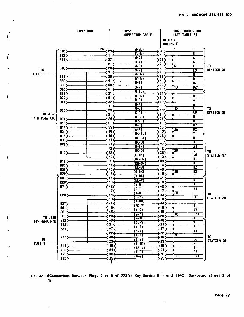
(
(
TO FUSE 7
T 7TH 48
0 J12B 4A KTU
T 8TH 48
0 J13B 4A KTU
TO FUSE 8
572A1 KSU
"'B12) B32'-B31<: ,
B10" .,
B11"' , B30" B29~ B20~ B13~ B3a~ B14~ .,
B35" .,
B34" . , B15 B14 82 B19 B39 B38
B17" ,
B18 B37 B38
>B22 B8 B28 B7 " , B28" .,
B27 BB B9 BO B12 B32 B31" ., 810,
B11 B30 B29
..... B20
P8 < 28( /
~ 1 ( 27( 2 (
~
' 28( 3 ( 29( 4 (
~
~ ~ ~ ) '
30( 5 ( 31 ( 8 ( 32 ( 7 ( 33( 8 ( 34 ( 9 (
... 35( 10 ( 38( 11 ( 37( 12 (
J
~ 38( 13(
) 39 ( 14 (
' 40( 15 ( 41 ( 18 ( 42 ( 17 (
J
) 43 ( 18 (
J
) ...
44( 19 ( 45( 20( 48( 21 ( 47 (
s ) ...
22( 48( 23 (
~
~
~
'
49( 24( 50( 25 ( I
ISS 2, SECTION 518-411-100
A25B 184C1 BACKBOARD CONNECTOR CABLE (SEE TABLE E)
BLOCK B COLUtiN E
(W-BL) )28) 1 T (BL-W)
a R ) 1 ) (W-iH a A
(O-W) )27) a A1 (W-G) ) 2 ) a5 L TO (G-W) ) 28) a LG STATION 35 (lii-BRJ ) 3 ) a H (BR-W) )29) a
B (lii-SJ )4 ) a BZ {S-W) )30) a10 BZ1 (R-BL) ) 5 ) a T (BL-R)
) 31) a R (R-0) )8 ) a A (0-R)
)32) a ) 7 ) a15
A1 (R-G) L TO (G-R)
) 33) a LG STATION 38 (R-BR)
) 8 ) a H (8R-R) )34) a B lR-SJ ) 9 ) a BZ (S-R) ) 35) a20 BZ1 (BK-BL) ) 10) a T {BL-BK) ) 38) a R (BK-0)
) 11) a A (0-8K) )37) a A1 (BK-G) ) 12) a25 L )38) a TO (G-8K) ) 13) LG STATION 37 (BK-8R) a H (BR-8K) )39) a B (BK-S) ) 14) 0 BZ (S-BK) ) 40) a30 BZ1 CY-BLI ) 15) a T (BL-Y) ) 41) a R (Y-O)
) 18) a A (0-Y) )42) a A1 (Y-G)
) 17) a35 L ) 43) TO (G-Y) a LG ) 18) STATION 38 (Y-BR) a H (BR-Y) )44) a B {Y-S) ) 19) a BZ (S-Y)
)45) a40 BZ1 (V-BL) )20) a T {BL-Vl )48) a R {V-0)
) 21) a A {0-V)
) 47) a A1
{V-G) )22) a45 L )48) 0 LG
TO (G-V) )23) a STATION 39 {V-BR) )49) H (BR-V) a B (11-SJ )24) a BZ (S-V) )50) a 50 BZ1
)25) a
Fig. 37-~nnections Between Plugs 5 to 8 of 572A1 Key Service Unit and 184Cl Backboard (Sheet 2 of 4)
Page 77

SECTION 518-411-100
TO FUSE 8
T 8TH 48
0 J138 4A KTU
T 9TH 48
TO FUSE 9
0 J14B 4A KTU
"'813 833 814
835" ·~
834 815 816 82 819 839" B3S(
'/
817' ,
818' B37~ B36(
>822 86 B26 B7
828'-.,
B27' 8 ~ 8 , 89 80 812 832 B31
810' .,
B11 B30 839 B20 B13 833 814
B35" .,
B34' ., 815 818 B2
'
572A1 KSU
P7 I 26E 1 E 27E 2 E
~
" 2s E 3 oE 29E 4 E 30 E 5 E 31 E 6 E
" 32E 7 E 33 E a E 34E 9 E
" 35E 10E 36 E 11 E 37E 12E
" ' 38 E
~ 13 E 39 E
~
~ 14E 40E 15E 41E 16 E 42E 11E
~ "
43 E 18 E
' 44E
" 19E
" 45E
" 2DE 46E 21 E 47 E
5 '
22E 48 E
" 23 E
) ) ~ ....
49 E 24 E 50E 25 ( I
A25B
I 184C1 BACKBOARD
CONNECTOR CABLE (SEE TABLE E)
BLOCK B COLUMN F
(W-BL) ) 26) 1 T (BL-W)
0 R
(W-Il} ) 1 A (O-W) ) 27) 0 A1 (W-G) ) 2 ) 05 L TO (G-W) ) 28) 0 LG STATION 40 lA-mn ) 3 ) 0 H (BR-W) ) 29) 0 B {A-S I ) 4 ) 0 BZ (S-W) ) 30) 0 10 BZ1 (R-BL)
) 5 ) 0 T jBL-R~
) 31) 0 R )6 (R-0) ) 32) A (0-R)
0 ) 7 ) 015
A1 {R-G) L TO {G-R)
) 33) 0 LG STATION 41 (R-8R)
) 8 ) 0 H (BR-R) ) 34) 0 B IR-SJ ) 9 ) 0 BZ (S-R)
) 35) 020 BZ1
{BK-BL) ) 10) 0 T (BL-BK) ) 36) 0 R (BK-0)
) 11) 0 A (0-BK)
) 37) 0 A1 (8K-G) ) 12) 0:!5 L TO ) 38) 0 [G (G-BK) ) 13) STATION 42 (BK-BR)
0 H (BR-BK)
) 39) 0 8 (BK-S) ) 14) 0 BZ (S-BK) ) 40) 030 BZ1 (V-BLj ) 15) 0 T (8L-Y) ) 41) 0 R (Y-O)
) 16) 0 A (0-Y) ) 42) 0 A1 (Y-G)
) 17) 035 l ) 43) TO (G-Y)
0 LG ) 18) STATION 43
(Y-BR) 0 H (BR-Y)
) 44) 0 B (Y-S) ) 19) 0 BZ (S-Y)
) 45) 0 BZ1 (V-BL) ) 20) 040
T (BL-V) ) 46) 0 R (V-0) ) 21) 0 A (0-V)
) 47) 0 A1
(V-G) ) 22) 0 45 L (G-V)
) 48) 0 LG TO
) 23) 0 STATION 44 (V-BR) H (BR-V) ) 49) 0 B li7-SJ ) 24) 0 BZ (S-V) ) 50) 050 BZ1
) 25) 0
Fig. 37 -·Connections Between Plugs 5 to 8 of 572A 1 Key Service Unit and 184C1 Backboard (Sheet 3 of
4).
Fage 78
(
(

(
( "B19'" ., B39'"
TO 9TH 484
J14B B3B~ A KTU .,
TO FUSE 9
TO 10TH 484
TO FUSE 10
J15B A KTU
B11'" ,
B18 B37 B38
>B22 B8 , B28, B7 '"
B28'" .,
B27 B8 89 BO .... , B12'" ., B32'" B31~ .,
B10'" .,
B11 B30 B29 B20 B13 B33'" B14~ ,
B35' .,
B34'" ., 815' ., B18 B2 B19 B39 B38
B17'" , B18 B37 B38
'B22
572A1 KSU
P8
;
/
'
" /
'
/
; ...
/
/
'
" ;
' )
I A25B CONNECTOR CABLE
28( (W-BL) (BL-W) 1 ( (W-!J;
27( (O-W) 2 ( (W-G) 28 ( (G-Irl) 3 ( (A-BRJ 29 ( (BR-W) 4 ( [A-S I 30( (S-W) 5 ( (R-BL) 31 (
IBL-Rl 8 ( (R-0) 32( (0-R) 7 ( (R-G) 33( {G-R) 8 ( (R-BR) 34 ( (BR-R) 9 ( [R-SI 35 ( (S-RI 10 ( (BK-BL)
38( (BL-BK) 11 ( (BK-0) 37 ( (0-BK) 12 ( (BK-G)
38( (G-BK) 13 ( (BK-BR) 39( (BR-BK) 14 ( (BK-S) 40( (S-BK) 15 ( (Y-BLI 41 ( (BL-Y) 18 ( (Y-O) 42( (0-Y) 17 ( (Y-G) 43( (G-Y) 18 ( (Y-BRI 44(
(BR-Y) 19 ( (Y-S) 45(
{S-Y) 20 ( (V-BL) 48 ( (BL-V) 21 ( (V-0) 47 ( (0-V) 22( (V-G)
48( (G-V) 23( (V-BR) 49 ( (BR-V) 24( (V-Sl 50( (S-V) 25 ( I
ISS 2, SECTION 518-411-100
184C1 BACKBOARD (SEE TABLE E)
BLOCK B COLUMN G
(28 ( 1 T a (1 ( R a
A (27 ( a A1 (2 ( a5 L TO (28 ( a LG STATION 45 (3 ( a H (29 ( a
B (4 ( a BZ (30 ( a10 BZ1 (5 ( a T (31 ( a R (8 ( a A (32( a
(7 ( a15 A1 L TO (33 ( a LG STATION 48 (8 ( a H (34 ( a B (9 ( a BZ (35( a20 BZ1 < 10 ( a T (38 ( a R < 11 ( a A (37 ( a A1 < 12 ( a25 L (38 ( TO a LG < 13( STATION 47 a H (39( a B < 14 ( 0 BZ
(40( 030 BZ1 < 15 ( 0 T < 41 ( 0 R < 16 ( 0 A (42 ( 0 A1 (11( a35 L (43 ( TO 0 LG < 18 ( STATION 48 0 H (44( a B < 19 ( a BZ (45 ( 040 BZ1 (20( 0 T (48( a R (21 ( 0 A (47 ( a
(22 ( 04~ A1 L
(48( 0 LG TO
(23( STATION 49 0 H (49( a
B (24( 0 BZ (50 ( a 50 BZ1 (25( 0
Fig. 37 -tconnections Between Plugs 5 to 8 of 572A 1 Key Service Unit and 184C1 Backboard (Sheet 4 of
4).
Page 79

SECTION 518-411-100
TO FUSE 11
T 11TH 48
0 J188 4A KTU
T 12TH 48
TO FUSE 12
0 J17B 4A KTU
"B6 B26 B7
B28,
B27' B8 ~ B9 ( 80 B12 B32 B31
B10' ,
B11 B30 B29 B20, B13 833 B14
B35' .,
834' B1S~ B1S~ B2.,
819 829 B38,
B17,
B18 837 B36
>B22 88 826' B7·~ ,
828' .,
B27' 88 ( B9 ( 80 ( ' ,
572A1 KSU A258 CONNECTOR CABLE
/
/
; '
~
' ' ' " " "
/
~
~
~ ) " /
; ; ; ~ ~
) )
<
> > > > > > > > > > > > > > > > > > > > > > > > > )
> > > )
> > > > > )
>
P9 26 ~(-----:(~W-:-'B7.L+-) ---7) 28 ) (BL-W)
1 < tw-o) > 1 > 27 ( 1 o-w 1 ) 21 > 2 ( ) 2 > 28 ( (W-G) ) 28)
(G-W) 3 < (w-HRI >3 > 29 ( (BR-W) ) 29) 4 < (w-sl > 4 > 30 ( ( s-w 1 ) so ) 5 ( ) 5 > 31 ( (R-BL) ) 31) 8 ( (8L-R) ) 6 ) 32 ( (R-O) ) 32 7 ( (0-R) ) 7 33 ( (R-G) ) 33 8 ( (G-RI ) 8 34 ( (R-BRI ) 34)
(BR-R) 9 ( (A-s) ) 9 35 ( (S-R) ) 35 10 ( (BK-BL) ) 10 38 ( (BL-BK) ) 38 11 ( (BK-OI ) 11 37 ( (O-BK) ) 37 12 ( (BK-G) ) 12 38 ( (G-BK) ) 38 13 ( (BK-BRI ) 13 39 ( (8R-BK) ) 39 14( (8K-S) )14 40 ( (S-BK) ) 40 15( (Y-BLI )15 41 ( (BL-Y) ) 41 16 ( (Y-O) ) 18 42 ( ( 0_ y I ) 42 17 ( (Y-G) ) 17 43 ( ( G-y I ) 43 18 ( (Y-BR) ) 18 44 ( (BR-YI ) 44 19 ( (Y-SI ) 19 45 ( (S-Y) ) 45 20 ( (V-BLI ) 20 46( (BL-V) )48 21( (V-Ol )21 47 ( (O-V) ) 47 22 ( (V-GI ) 22 48( (G-VI ) 48 23 ( (V-BR) ) 23 49 ( (BR-V) ) 49 24 ( (v-s) ) 24 50 ( (S-VI ) 50 25( )25 I
184C1 BACKBOARD (SEE TABLE E)
BLOCK B COLUMN H
1 T a R a A a A1
a5 L a LG a H a B a BZ
a10 BZ1 a T
a R a A a A1
a15 L a
LG a
H a
B a
BZ a20 8Z1 a
T a
R a
A a
A1 0
25 L a LG a
H a B a
BZ a30 BZ1 a T a
R a A a
A1 a35 L a
LG a
H a
B a
BZ a40 BZ1 a
T a
R a
A a
A1 a45 L a LG a H a B a BZ a 50 BZ1 a
....
<
<
<
<
,
TO STATION 50, OR CODE 70 (ALL ZONE PAGING)
TO STATION 51, OR CODE 71 (PAGING ZONE 1)
TO STATION 52, OR CODE 72 (PAGING ZONE 2)
TO STATION 53, OR CODE 73 (PAGING ZONE 3)
TO STATION 54
Fig. 38-.Connections Between Plugs 9 to 11 of 572A 1 Key Service Unit and 184C1 Backboard (Sheet 1 of
3).
Page 80
(
(

(
(
TO FUSE 12
TO 12TH 484
J178 B KTU
0 J18B T 13TH 48
TO FUSE 13
4A KTU
..... B12 Bs2( B31' ,
B10' ,
B11' aso' B2s' ., B20, B13 B33 B14
B35' .,
B34' B15~ B1S~ 82.,
B19 B39 B38
B17' ,
B18' Bs7~ B38~ .,
>B22 BS B28 B7
B28' .,
B27' 88, B9 , BO B12 B32 B31
B10' .,
B11 B30 B29 B20
"
572A1 KSU
P10 /
; ; '
~
) ; ..
/ ...
~
) '
~ ...
< /
'
ISS 2, SECTION 518-411-100
A25B 184C1 BACKBOARD CONNECTOR CABLE (SEE TABLE F)
I BLOCK C COLUMN A
(W-BL) ) 28) (BL-W) 28~(------~~~--~
1 ~(------~~~--~ 27~(------~~----~ 2 ~(------~~----~ 28~(------~~----~ 3 ~(-------Trr.....;..._...--~
29~(------~~~--~
4~(---.;.rr.;:~-~ 30~(------0A~----~ 5 ~(------~-::-~--~ 31~(------~~~--~ 8 ~(-------+='~"'---~ 32~(------~~----~ 7 ~(-------+=-.....;:+----~ 33~(------~~~--~ 8 ~(------......;.:.-:=-.,.---~
34~(------~~~--~ 9 ~(-------TW;.;,.;r.:...__4
{l;j-IJ) ) 1 )
(0-W) ) 27)
(W-G) ) 2 )
(G-W) ) 28)
tw-BR) ) 3 )
(BR-W) ) 29)
(w-s) ) 4 )
(S-W) ) 30)
(R-BL) ) 5 ) ) 31)
(BL-R) ) 8 ) (R-0) ) 32) (O-R) ) 7 > (R-G) ) 33) (G-R) (R-BR) ) 8 > (BR-R) ) 34)
) 9 ) (R-s) (S-R)
) 35)
(BK-BL) ) 10)
(BL-BK) ) 38)
(BK-0) ) 11)
(0-BK) ) 37)
(BK-G) ) 12) ) 38)
(G-BK) ) 13) (BK-BR) (BR-BK) ) 39)
(BK-S) ) 14)
(S-BK) ) 40)
(Y-BLJ ) 15)
(BL-Y) ) 41)
(Y-O) ) 18)
(0-Y) ) 42)
(Y-G) ) 17) ) 43) (G-Y) ) 18 > (Y-BR)
(BR-Y) ) 44)
(Y-Sj ) 19)
(S-Y) ) 45)
(V-BL) ) 20)
(BL-V) ) 48)
(V-0) ) 21)
(0-V) ) 47)
(V-G) ) 22) ) 48)
(G-V) ) 23) (V-BR) ) 49) (BR-V) tV-sJ ) 24)
(S-V) ) 50) ) 25)
I
35~(------~~~--~ 10~(-----~~~--~ 38~(------~~~--~ 11 ~(---------=-=~~---+ 37~(---------=-=~~--~ 12~(-------n~~--~ 38~(------~-::'!"!"~--4
13~(------+=~,..._-~ 39~(------~=-=;.;.;.....--4
14~(-------n~~--~
~~(---~~~-~ 15 ~(-------Tt....-;n-T----+ 41~(------~~~---+ 18~(---~~~-~ 42~(------~~-----+
17~(------~~----4 43~(------~~~---+
18~(-------+.;...,;..or..-----+
44~(------~~~---+
19~(----rn=-::~-~ 45~(------~~----~ 20~(------~~~--~ 48~(------~~r---~ 21~(------~~~--~
47~(------~~----~
22~(------~~~--~
48~(------~~----~ 23~(------~-=~--~ 49~(-------n~ri---~ 24~(-------n~~---+ 50~(----~~--~ 25~(------~~~--~ I
01 0 0 05 a 0 0 0 a10 0 0 0 0 015 0 0 a 0 0
20 a 0 0 0 025 0 0 0 0 030 0 0 0 0 035 0 0 0 0 0
40 0 a 0 0 0 4! 0 0 0 0 050 0
T R A A1 L LG H B BZ BZ1 T R A A1 L LG H B BZ BZ1 T R X A1 L LG H B BZ BZ1 T R A A1 L LG H B BZ BZ1 T R A A1 L LG H 8 112 BZ1
TO STATION 55
TO STATION 58
TO STATION 57
TO STATION 58
TO STATION 59
Fig. 38-.Connections Between Plugs 9 to 11 of 572A 1 Key Service Unit and 184C 1 Backboard (Sheet 2 of
3).
Page 81

SECTION 518-411-1 00
TO FUSE 13
0 J188 T 13TH 484 A KTU
572A1 KSU A25B 184C1 BACKBOARD CONNECTOR CABLE (SEE TABLE E)
I BLOCK C COLUMN E
(W-BL) (BL-W)
) 26 )
(W-0) ) 1 )
(0-W) ) 27 ) ) 2 )
"813 833 814
P11 26~(---.....!.,;~=-!--------4
835' " ., ... (W-G) (G-W) ) 28 )
1 ~(---~:..,.;:..:~-4 27 ~(-----;..;,......,;,.:-------4 2 ~(---~....;.;..;....--4 28~(---...;..;;......;:;.;...--4
3 ~(---....;.,.......,;,.,.---4
29~(---~~~--4 4 ~(-----;.;;,:..:.,..;,;.:---4 30~(---~~~--4 5 ~E---.....!,;:......:;.!'-,----4
31~(---~~~--4
8 ~(---~~:.L---4 32~E---~~~--4
7 ~( -----!-;;....:.;..?.---~
33~(---~~--4 8 +-(---....;.=-..;,;:..,--4 34~(---~~~--4 9 ~(---...;;o;.~--4 35~(---...:,.._....:....:....--4
10~(-----!-i,~-;---4
{w-8R) ) 3 )
(BR-W) ) 29 )
(w-SJ ) 4 )
(S-W) ) 30 )
(R-BL) ) 5 ) ) 31 )
!BL-Rl ) 6 ) (R-0) (O-R)
) 32 ) ) 7 )
' 834 815 816 82 819 839 838
(R-G) (G-R)
) 33 ) 817" f , )
(R-BR) ) 8 )
(BR-R) ) 34 )
(R-s) ) 9 ) ) 35 )
818 '
837 836
(S-R) (BK-BL) ) 10 ) 822)
(BL-BK) ) 36
(8K-0) ) 11
(0-BK) ) 37
>-------~36~(---~~~--4 >-------~11~(---.....!.,;~~--4
>-------<37~E---.....!,;~~--4
(BK-G) ) 12
(G-BK) ) 38
(BK-BR) ) 13
(8R-BK) ) 39 ) 14
)
(8K-S) (S-BK) ) 40 )
12~(----.+=;,..=.;,n----4
>-------<38~(---~~~--4
---------<13~(---.....!.,;~~--4
>-------<39~(----~~~--4
>-------<14~(----+=~~--4
>-------<40~(---~~~--4
~------<15~(----~~~--4
>-------<41~(---~~~--4 >-------<16~(---~~~--4
>-------<42~(----~~---4
(Y-BL) ) 15 '
(BL-Y) ) 41
(Y-O) ) 16 ) 42
(0-Y) (Y-G)
) 17 ) 17~(-----:-;:~~--4
~.> -------<43~(---~~~--4 (G-Y) ) 43 )
(Y-8R) ) 18
(BR-Y) ) 44 ) 19
-----------<18~(---~~~--4
2 44~(----~~~--4 .. 19~(---~;:.:..,...;;....!---4 (Y-S)
(S-Y) ) 45 ) >-------<45~(---~~~---4
>-------<20~(---~~'-,----4
>-------<46~(---~~~--4
>-------~,21~(---~~~-~ >-------~47~(---~~:----4
(V-BL) ) 20 )
(8L-V) ) 48
(V-0) ) 21 ) 47
(0-V) (V-G) ) 22
(G-V) ) 48
(22~(---~~--4
>-------<48~(---~~~--4
(V-BR) ) 23
(BR-V) ) 49
(v-s) ) 24
(S-V) ) 50 ) 25
------------<23~(---~~~--4
>-------<~49~(---~~~--4
>--------<~24~(----;.r;~r-:---4
~--------<~50~(---~~~-~
~------<'25~<---~~~-~ ' I '
)
) )
1 a a a a5 a 0
a a a10 a a 0
a a15 a 0
a a
a20 a
0 25
0 30
a35 0
0 40 a ,
a45
a 50 0
T R A A1 l LG H B BZ BZ1 T R A A1 L LG H B BZ BZ1
TO STATION 80
TO STATION 81
Fig. 38-.Connections Between Plugs 9 to 11 of 572A 1 Key Service Unit and 184C1 Backboard (Sheet 3 of
3).
Page 82
(
(

(
(.
ISS 2, SECTION 518-411-100
572A1 KSU
P13 P9
\S-
BLOCK A
5
PAGING CODES --~ 70-73 AND STATION 54
P4 PO
-~-~ L (SEE NOTE) ---,
BLOCK B I NOTE: IF BLOCK B IS ADDEO FOR EXPANSION ROUTE CABLE SHOWN BY DASHED LINE TO ACCESS CODES 25-29.
STATIONS 25-29
A. S"ALL SYSTE" USING ONE BLOCK INITIALLY AND HAVING PAGING ACCESS
572A1 KSU
P13 P9
\S-
BLOCK A
STATIONS 25-29 --~
P4 PO
-~
BLOCK B
STATIONS 50-54 OR PAGING CODES 70-73 AND STATION 54
B. LARGER SYSTE" INITIALLY USING TWO BLOCKS WITH OR WITHOUT PAGING ACCESS'
Fig. 39-Cabling Methods When Paging Access is Supplied
Page 83

, __
SECTION 518-411-100
Page 84
110A APP PIOUNTING (NOTES 2 AND 5)
OFF-PREPIISES R 4 / 13
TELEPHONE SET T 3 " (NOTE ~) " 12
'
8B KTS (NOTE 3)
(NOTE 4) -
T 1 1";-111,.....,.~~~=;-t~;------<< 14 ~----~ ~R---h~~~'~~~-2------<" 9 A '(..( 10 ' r-~H,.....,.zr~~~~+-o-------<j 1 BZ """ 5 " r-~H"""~~-+-++-o-------<"' 18 ~---1 BZ1 df-- 8 "
~'+---' '----
A BAT 45 ------+-----------4-~--~--~/ 18 ~--~ A GRD 48 " ------+-----------4-~--~--~" 3 B BAT 47 ' ------+-----------4-~--~--~/ 17 ~--~ B GRD 48 " ------+-----------4-~--._--~j 15 +---~ 105t 39 ------+-----------4-~------~/ 10 ~--~
KTS POWER 8 ~ 8 SUPPLY RG l 9 "
NOTES: 1. PIAXIPIUPI STATION CONDUCTOR LOOP IS 500 OHMS. TELEPHONE
420A KTU
TB1
SET PlAY BE EQUIPPED WITH A TOUCH-TONE DIAL PROVIDED 88 KTS IS SO EQUIPPED. WIRE SET WITH BRIDGED RINGER.
2. PlAKE CONNECTIONS ON LEFT BLOCK IF 420A IS IN P1 OR ON RIGHT BLOCK IF IN P2.
3. ANY DIGIT PlAY BE ASSIGNED TO OFF-PREPIISES STATION. TE~INATE LEADS ON 184C1 BACKBOARD DEPENDING ON CODE ASSIGNED.
4. 521AA DIODES PIUST BE INSTALLED FROPI TIP AND RING TO GROUND AS SHOWN. USE CONNECTING BLOCK AS SHOWN AS TE~INATING POINT.
5. IF PIORE THAN TWO 420A KTUS ARE REQUIRED, A 842A PANEL CAN BE USED.
fig. 40-.Connections for Off-Premises Extensiont
ADD STRAPS
(
_.
(

(
(
RI
K1 BI
A ~f ~ ,.
BZ '-"
,.--~4" Sl BZ1
RI
81 K2 .........
~ A ~t" 1-
BZ ~
BZ1 '-"
'--H4"s~ 1-- t105
AC-G .._
342A ADAPTER
RI ..,
CKT1 GRD
RI CKT2
GRD
"
ISS 2, SECTION 518-411-100
TO EXTERNAL SIGNAL DEVICE NGER OR LOUD RI
BZ CKT1
BZ1
BZ CKT2
BZ1
TO ASSOCIAT
TO 68 KTS TER .. INAL BLOCK
"~] GRD FREQUENCY G ED KTS ENERATOR
Fig. 41-t<Annections for External Signal or Loud Ring (324A Adapter).
Page 85 85 Pages