
Digital image analysis system for monitoring crack growth at elevated temperature(Final Report, 15...
33
Strainoptic Technologies, Inc. 108 West MotoeyAvenue North Wales, PA 19454 May 1988 Final Report for Period July 1987 - January 1988 Approved for Public Release; Distribution is Unlimited DTIC AUG 1 0166 H FLIGHT DYNAMICS LABORATORY AIR FORCE WRIGHT AERONAUTICAL LABORATORIES AIR FORCE SYSTEMS COMAN WRIGHT-PATTERSON AIR FORCE BASE, OHIO 45433-6553 Arkd cyS .ol os c Fina "l otIC roproduct- FLIG HT in bAaM c aRA
Transcript of Digital image analysis system for monitoring crack growth at elevated temperature(Final Report, 15...

Strainoptic Technologies, Inc.108 West MotoeyAvenue
North Wales, PA 19454
May 1988
Final Report for Period July 1987 - January 1988
Approved for Public Release; Distribution is Unlimited
DTICAUG 1 0166
H
FLIGHT DYNAMICS LABORATORYAIR FORCE WRIGHT AERONAUTICAL LABORATORIES
AIR FORCE SYSTEMS COMANWRIGHT-PATTERSON AIR FORCE BASE, OHIO 45433-6553
Arkd cyS .ol os cFina "l otIC roproduct-
FLIG HT in bAaM c aRA

NOTICE
WHEN GOVERNMENT DRAWINGS, SPECIFICATIONS, OR OTHEP DATA AREUSD FOP ANY PURPOSE OTHER THAN IN CONNECTIO WITH A DEFIVITFLYGOVERNMENT-RELATED PROCUPEMENT, TfHE UNITED STATES GOVERNMENTINCURS NO RESPONSIBILITY OR ANY OBLIGATION WHATSOEVER. THE FACTTHAT THE GOVERNMENT MAY HAVE FORMULATED OR IN ANY WAY SUPPLIEDTHE SAID DRAWINGS, SPECIFICATIONS, OR OTHER DATA, IS NOT TO BERFGARDED BY IMPLICATIOM, OR OTHERWISE IN ANY MANNER CONSTRUED, ASLICENSING THE HOLDER, OR ANY OTHER PERSON OR CORPORATION; Or ASCONVEYING AMY RIGHTS OR PERMISSION TO MANUFACTURE, USE, OR SELLANY PATEPTED INVENTION THAT MAY IN ANY WAY BE RELATED THFPFTO.
THIS PEPOrT HAS BEEN REVIEWED BY THE OFFICE OF PUBLIrAFFAIRS (ASP/CPA) AND IS RELEASABLE TO THE NATIONAL TECHNrICALINFORMATION SERVICE (NTIS), AT NTIS, IT WILL BE AVAILABLE TO THFGENERAL PUBLIC, INCLUDING FOREIGN NATIONS.
THIS TECHNICAL REPORT HAS BEEN REVIEWED AND IS APPROVED FOrPUBLICATION,
------------! _- _- ----. . . . . . . . . . . . . . . . . . . -------
ARVIND NAGAR, Project Engr DONALD B. PAUL, Actg ChiefFatigue, Fracture & Reliability Gp Structural Integrity Branch
Structural Integrity Branch Structures Division
FO. THE COMMANDER
FREDERICK L. DIETRICH, Col, USAFChief, Structures Division
IF YOUR ADDRESS HAS CHANGED, IF YOU WISH TO BE REMOVED FROMOUR MAILING LIST, OR IF THE ADDRESSEE IS NO LONGER EMPLOYED BYYOUr OBBANIZATION PLEASE NOTIFY A.WAL/FIBEC , WRIGHT-PATTERSON AFB,nH IJ4>>--6553 TO HELP US MAINTAIN A CURRENT MlAILING LIST,
COPIES OF THIS REPORT SHOULD NOT BE RETURNED UNLESS RFTURNIS PCOUIRED BY SECURITY CONSIDERATIONS, CONTRACTUAL OBLIGATIONS,OR NOTICE ON A SPECIFIC DOCUMENT,

REPORT DOCUMENTATION PAGE O# "sI&. REPORT SECURITY CLASSIFICATION 1b. RESTRICTIVE MARKINGS
2. SECURITY CLASSIFICATION AUTHORITY 3. OSTRIOUT IONIA VAAI RMUT OF REPORT
2 b. DECLASSIFICATWO/OWGADING SCHEDULE Distribution is Unlimited
4. PERFORMING ORGANIZATION REPORT NUMAE(S)5.MNTRGOGAIAONEPTNME()
Sales Order #88104 AFWAL-TR'-88-3Q3O
6. NAME OF PERFORMING ORGANIZATION 6 b. OFFICE SYMBOL ?a. NiAMEfOF MONITORING OGNZTO
StrinoticTehnoogis, I (N^W Flight Dynamics Laboratory (AFWAL/FIECStranopic echoloiesInc ___________ Air Force Wright Aeronautical Laboratories
k ADDRESS (City. State, &Wi ZFCofs) 7b. ADDRESS WAiY. stte. SowE ZIP ui108 West Montgomery AvenueNorth Wales, PA 19454 Wright Patterson AFB, OHi 45433-6553
G&. NAME OF FUNDING /SPONSORING 6 b. OFFICE SYMBOL 9. PROCUREMENT INSTRUMENT IDETIICATION NUMBERORGANIZATION if SA~kStrainoptic Technologies, Inc F33615-87-C-3233
kZ ADDRESS (Cfty, State. and ZIP Code) '10 SOURCE OF FUNDING NUMBERS108 West Montgomery Avenue PROGAd PROJECT ITASK IWORK UNITNorth Wales, PA 19454 ELEMENT NO. N(0 NO CCSSION NO.
_______________________________65502F I TOOI 30 f911. TITLE (find Sftuvdtp C00SfKC1bon)
DIGITAL IMAGE ANALYSIS SYSTEM FOR 11MII1DU CRAa QGJdH AT HLVAIED THIPEAITh
12. PERSONAL AUTHOR(S)Redner, Alex, S. and Voloshin, Arkady, S.
13&. TYPE OF REPORT 13b. TIME COVERED 14. DATE OF REPORT (YwMAft .e S5. PAGE COUNTFINAL FRO7-5..LTojl-1-8 1988 July 32
16. SUPPLEMENTARY NOTATION "Export Control Res'trictions Apply"
This is a Small Business Innovation Research Programr Report
7.COSATI CODES 16. SUBJECT TERMS (Cenbain on ff eovw &W cfta* b 10 rAdFIELD GROUP SUB-GROU
13 1
1~ ~ KW. ABaAT( nhmn avwue nacmy ow d M by bw numbe)
SUMMARY -NEXT PAGE
2DiSTRIU.aIV.AILIT VOF A2TRC - 1. ABSTRACT SECURITY CLASSIFCATIONC UNCLASSIFIEDIUNLIMIIED WSAME AS RpT. DOTIC LamR Unclassified
22a NAME OF RESPONSIBLE INDIVIDUAL. 22b TELEPHONE (N*#a At" C*) 22c OFFIC SYMBOLMr. Arvind Nagar (513) 255-6104 AFWAL/FIBEC
DO Form 147. JUN M pmam*, gooftw SECURITY CtLAU 4 OF THIS PAGEUNCLAS SIF~IED

TABLE OF CONTENTS
PAGE
1. SUMMARY ............................................................ 1
2. PHASE I RESEARCH OBJECTIVES ........................................ 2
3. DESCRIPTION OF THE MEASURING SYSTEM FOR MONITORING CRACK GROWTH .... 4
3.1. Transmission of the Specimen Image to the Digital Analysis System 5
3.2. Linear Motion, Digitally Controlled Stage for Positionning of theViewing Camera and Penetrator .................................... 11
3.3. Digital Image Analysis System .................................... 17
4. RESOLUTION OF THE SYSTEM ........................................... 21
5. TEST RESULTS ....................................................... 22
5.1. System Components ................................................ 22
5.2. Test and Evaluation of the Optical System ........................ 22
5.3. Testing of the Positionning Stage ................................ 26
5.4. Testing of the System ............................................ 26
5.5. Conclusions ...................................................... 27
6. RECOMMENDATION - FUTURE RESEARCH ................................... 28
6.1. Extension of Temperature Range to 27000 F ........................ 28
6.2. Research on Methods of Absolute Position Indexing Using DigitalImage Analysis ................................................... 28
6.3. Illumination Methods ............................................. 28
6.4. Handling Methods in a Variable Temperature Loading Spectrum ...... 28
6.5. Software Development ............................................. 28For
DTIC TAB L
tiJustif l
Dimtribution/
Availability Codes
,Avail and/or!W st 1 Special, '

i. SUMMARY
The objective of the research work reported here was to develop a new con-cept~based on Digital Image Analysis,for monitoring the crack-tip positionat elevated temperatures.
The proposed system includes: -
a) CCD camera observing the crack-tip.
b) PC-based frame grabber, capturing a 512 x 512 pixel frame.
c) Digital Image Analysis software developed to locate and digitize theposition of the crack-tip, on the observed image area.
d) Step-motor driven stage, permitting the image-transmitting penetratorto follow-up the tip as it advances.
e) A penetrator (fiber-optic or lenses) transmitting the magnified imagefrom the vicinity of the crack-tip to the camera.
In the course of the research work, the system was designed, assembled, andtested. Also, a program was developed for digitizing the crack-tip position.To evaluate the feasibility of the concept, its potential accuracy, resolution,temperature limitation and usefulness the system was tested at room andelevated temperature.
The results of the testing and evaluation prove that the proposed conceptis feasible, practical, and capable of performing at temperatures exceedingour initial objectives.
Potential Application of the Research Results
The measurements of crack-tip advance is performed daily by hundreds of labora-tories, investigating material fatigue properties and fracture behavior.
These measurements are labor-intensive operations, requiring fequent micro-scope-assisted observation and delicate micrometer-eyepiece adjustments.The precision required is difficult to achieve, using visual judgment. Still
the results of these measurements are critical in the design and in assessingthe performance of critical components subjected to cyclic loads and vibration,
such as turbine blades, aircraft structural components and hundreds of otherstructural elements in automotive industry.
The newly developed concept, using Digital Image Analysis as replacement ofthe visual follow-up, and offers:
- Labor saving- Automation of the data acquistion.- Objective interpretation- Extension to 20000 F and above, not presently feasible
We expect that the system, when fully developed, will find a broad commercialmarket.
-1-

2. PHASE I RESEARCH OBJECTIVES
The objective of the Phase I research reported here was to develop andevaluate the feasibility of a novel system, capable of monitoring the crack-tip progress at elevated temperature reading 20000 F, using Digital ImageAnalysis for observation and location of the crack-tip coordinates.
The successful completion of this research demonstrated the feasibility ofa potentially powerful tool for in-situ, real-time, automated crack-tippropagation monitoring. The developed methodology, not only significantlyincreases the accuracy of the crack-tip determination, but it also eliminatesthe uncertainty associated with the human decision on the exact location ofthe crack-tip. In addition, a correct log of crack-tip position versus actualtime and number of cycles is automatically saved in a computer readable form,thus allowing for immediate analysis with any applicable software packages.
The importance of this newly developed technique, reported he2, is furtheremphasized by an extensive round-robin study conducted by fifteen differentlaboratories with several test specimen geometries, in order to develop arecommended practice for fatigue crack-growth rate testing. The results ofthis study (1) were evaluated statistically, and the variability and biasassociated with both analytical and experimental aspects of crack-growth ratetesting were determinated.
The results of the study showed that the primary source of variabilityassociated with fatigue crack-growth rate testing is the experimental pro-cedure used to obtain the raw test data - crack length versus elapsed cycles.
The problems and difficulties associated with accurate crack-tip positionmonitoring are multiplied ten-fold, when there is a need for a high-temperatureapplication.
A recently published paper (2) described the work on crack-growth evaluationin INCONEL 718 Alloy at 6500 C. This work was based mainly on the experimentaldata derived from the crack-tip position measured at this high temperature.Another application was presented (3), where crack-growth rate was evaluatedin the blade of a modern gas turbine, which operates at 9250 C. During eachflight, this component undergoes a large number of thermally induced stress-strain cycles, which may cause crack growth. Those and many other examplespoint to the necessity of an accurate, non-contact technique for automateddata acquisition for the crack-tip position.
The research undertaken in this project faced the technical challenge ofintegrating the known principles of the visual crack-tip monitoring approachwith the Digital Image Analysis system to create a working system capable ofautomated monitoring of the fatigue crack-growth rate. Since the modernDigital Image Analysis system components became easily available, severaluses for experimental strain and stress analysis were developed. Applicationsto photoelasticity and Moire were recently described elsewhere (4, 5).
-2-

Newly developed materials for high-temperature application need to betested, and data has to be acquired for crack-growth rate versus number ofloading cycles. This process is extremely complicated and, because of theneed for constant human interaction with the data gathering, is prone to
human errors. Those errors may destroy efforts of the long and expensive
high-temperature test. The methodology developed and described here can beexterded to high-temperature applications, opening a new avenue for the
testing without all the difficulties associated with human interpretationof the crack-tip position. Only the high-temperature quartz lenses will beexposed to the realm of 2000-2500* F heat.
All the necessary optical information is transmitted to a CCD video camerathrough an organized fiber-optic bundle, thus eliminating any human inter-ference with the process of data gathering. Human intelligence is neededfor data analysis, interpretation and conclusions, not for data acquisition,which can be handled much more efficiently and accurately by computer-basedImage Analysis system.
REFERENCES
1. Clark, W. G. and Hudak, S. J., "Variability in Fatigue Crack Growth RateTesting", Journal of Testing and Evaluation, JTEVA, Vol. 3, #6, 454-476, 1975.
2. Diboine, A. and Pineau, A., "Creep Crack Initiation and Growth in INCONEL718 Alloy at 650"o, Fatigue and Fracture of Engineering Materials andStructures, 10 (2), 141-151, 1987.
3. Marchand, N. J., Pelloux, R. M. and Ilschner, B., "Non-Isothermal FatigueCrack Growth in Hastelloy - X", Engineering Materials and Structures, 10(1),59-74, 1987.
4. Voloshin, A. S. and Burger, C. P., "Half-Fringe Photoelasticity: A NewApproach to Whole Field Stress Analysis", Experimental Mechanics, 23(3),304-313 (1983).
5. Voloshin, A. S., Burger, C. P., Rowlands, R. E. and Richard, T. G.,"Fractional Moire Strain Analysis Using Digital Imaging Techniques", ExperimentalMechanics, 26(3), 254-258, (1986).
-3-

3. DESCRIPTION OF THE PROPOSED MEASURING SYSTEM FOR MONITORING CRACK GROWTH
The system using the DIA for monitoring the crack-tip position is shown
schematically on the Figure 1.
The specimen under investigation is subjected to a cycling load at room orelevated temperature. As a result of loading spectrum, the crack length "a"increases. The crack growth&a must be recorded as a function of time ornumber of load cycles N, in order to evaluate the material toughness, ofother desired material properties. The region that includes the crack-tipis observed by the CCD-TV camera, and the acquired image is digitized andstored in a 512 x 512 points (pixel) format by the IMAGE GRABBER board,installed in a PC-AT computer. This stored quantitative photo is thenanalyzed, looking for discontinuities in a vertically scanned light intensity,revealing the a(x) and a(y) position of the crack-tip. As the crack-tip
advances, a new "x" (or *y") position of the tip reveals quantitatively thecrack length increase Aa, as function of time, or function of number of cycles N.
As the crack approaches the end of the area observed by the camera, a steppingmotor is instructed to drive the stage, moving the camera to a new position,defined by the program and selected in accordance with the observed field ofview.
The scan for measuring &a can be continuous, or can be initiated by timeinterval (a vs. time) or N count (a vs. N). In the system that wasused, the scan time for one frame acquisition was 1/30 seconds.
One monitor is used to display a(x) and the prompts for the system operation,while the other monitor displays the image observed and is useful for initialfocusing and position adjustments.
Since in most installations the furnace windows are too small to properlyfollow-up a long crack, and are too far from the specimen to provide adequatemagnification, a penetrator was developed for carrying the image from thevicinity of the crack-tip back to the camera. The penetrator moves togetherwith the camera and follows the crack-tip, permitting the observation of thecrack-tip at high magnification. The span of the follow-up was 100mm (4 in.).
Strainoptic and Dr. Voloshin of Lehigh University developed software forinterpretation of the observed image and retrieval of information. Thesoftware permits the measurements of the crack-tip position advance, issuescommand to the stepping motor and interprets the a vs. N information interms of the fracture mechanic parameters.
-m4-

0 *
0 0w w
Cy 0 Ll Ow I tf
3: < Lii
0 <
0 w
< UI)
Z- C-
U '-, LLJ
z -5-

3.1. Transmission of the Specimen Image to the Digital Analysis System
A. Visual Observation of the Crack-Tip Position
Using visual inspection, the region of the specimen containing thetip of the crack is directly observed using a microscope at low tomedium magnification level. Use of high magnification is notpractical, since it limits the size of the observed area and makesit difficult to see reference marks or scale.
a) The crack-tip progress can be monitored using a micrometer eye-piece in the microscope, measuring the distance to the nearestreference line, on the specimen, or on the attached scale.
b) As an alternative solution, a traveling microscope (or telescope)can be used. The cross-hair of the eyepiece is moved to thenew crack-tip position, and the measured motion provides thenthe crack-tip advance.
The above visual procedures require skill and experience, mostlywhen using a micrometer eyepiece. The procedure (b) does notaccount for the lateral motion of the specimen, and is mostly use-ful for room temperature observation.
The visual observation at elevated temperature becomes difficult.Using a window, one can see the specimen and use the procedures (a)or (b) above, provided the window size is sufficiently large tofollow-up the crack-tip. The hot air motion introduces a randomfluctuation of the image affecting seriously the visibility andthe precision.
The visual observation is labor-intensive, lacks the continuityand becomes impractical at high temperature.
3.1.1. Image Transmission for Digital Image Analysis
The concept of measuring the crack-tip position using the DigitalImage Analysis is similar to the visual concept, except that theanalysis of the image is performed by the computer, rather than human
interpretation.
The logic of the image interpretation needed to locate the tip ofthe crack is discussed in 3.4.1 below.
Once the crack-tip position is digitized, the progress can be measuredusing approaches similar to visual (a) and (b) above, measuring the
crack-tip positon with reference to:
- Previous position- Reference on the specimen- Edge- Translator stage position
-6-

Three methods of the image transmission to the camera are possible,
and were analyzed for their practical usefulness in this study.
3.1.1.1 Direct Observation
Figure 2 below shows schematically the direct observationconcept.
DIGITAL IMAGE ANALYSIS-SPECIMEN
WINDOWla vs. NJ. . .. . . . 1 - " | T
CCD CAMERA I A
STEPPING MOTOR__ _._ CONTROLLER
TRANSLATIONSTAGE FIGURE 2
For room temperature testing, this is a simple and practicalsolution. The CCD camera observes directly the specimen.The camera is mounted on a digitally-controlled translationstage that moves the camera to a new position, whenever thecrack progress requires repositionning.
At elevated temperature, this approach is less practical,since it requires a large access window. Also, as mentionedabove, hot air currents degrade the image quality and theresolution.
3.1.1.2 Penetrator
In order to eliminate the difficulties due to a limitedwindow size, and hot-air eddies typical of direct observation,a penetrator was designed to carry the image from the specimento the camera.
The penetrator requires only a small 20 mm (* in.) diameterhole in the furnace side-wall and permits to locate theobjective lens (1) within approximately 15 mm (5/8 in.) fromthe specimen, reducing considerably the image distortion dueto the hot-air motion.
-7-

Two designs (Figures 3 and 4) were tested for evaluation of
their relative merits and limitations.
a) Fiber-Optic Penetrator
In the fiber-optic penetrator design, the objectivelens (1), (See Figure 3) forms the image of the tip ofthe crack on the face of a fiber-optic image-transmittingguide.
The same image (1:1 ratio) is transmitted and becomesvisible at the other end of the guide, and projected bymeans of the camera imaging lens (2) (Figure 3) on theCCD sensor of the camera.
b) Relay-Lens Penetrator
The relay-lens penetrator is identical to the abovedesign, except that it replaces the fiber-optic guide bya set of relay lenses (See Figure 4) to carry the imageof the crack-tip to the camera sensor.
In both (a) and (b) penetrator designs (Figures 3 and 4), thelength of the penetrator was arbitrarily set at 300 mm (12"),and the OD at 19 mm (Q in.) fitting our high-temperaturefurnace. The specimen side (lens 1) was equipped with afused-silica lens, and right-angle prism, forming the imageon the tip of the image guide.
On the camera-side a glass lens was used to project the fiber-optic image guide on the camera CCD chip. For thefiber-opticpentrator, the IMAGE GUIDE was selected after reviewingseveral suppliers. The IMAGE GUIDE procured for experimenta-tion was 6.35 mm diameter coherent bundleconsisting of fused12 micron preform fibers.
For the relay-lens penetrator, a telecentric lens system wasdesigned, including quartz lenses at the hot end, and glass
lens at the camera end.
The relative performance of these concepts is discussed inTest Results and Conclusions.
-8-

U V) wU-J
w
f.D 0
zz
z C) LrJU
4jc- w1m -- M
w 0U
>wz Z)tzr
C) - 0
L.
_ 0rLLI-
2z LL- w I9-

cc0
Cw z
w
z
Lu zcc 0
cr -j U-)
2 OLuI
UU>> 0<
Li
LL >
LU-10-

3.2. Linear Motion, Digitally Controlled Stage for Positionning of theViewing Camera and Penetrator (Figure 5)
The objective of this stage is to automatically position the viewinghead, that includes the CCD camera with the pentrator and maintain thecrack-tip within the field of view.
The desired travel was 100 mm with the precision of positionning com-patible with the system, as discussed below. The stage was designedby Strainoptic Technologies, Inc.
3.2.1. Selection Criterion for Stage Motion Drive Control
A motion control system typically consists of Translator/Driver,communications port, and power supplies. In most cases each of thesecomponents is sold separately by manufacturers. While they do pro-vide flexibility to the user, they require the user to install cardsin the computer. Experience has shown that motor controller cardsinstalled in the computer sometimes tend to produce interferencein image processing hardware. Purchasing individual components mayalso involve a considerable amount of user wiring.
These were some of the factors we considered during our market surveyand decided to acquire a Superior Electric motor controller/driver.It offered the following advantages over other reputed manufacturersof motion control systems:
a) The Translator/Driver, communications port and power supplywere all enclosed in one, stand-alone unit known as the "indexer"module. This arrangement minimizes user wiring requirements.
b) The communications port had a standard RS 232 serial interface.
c) The indexer is capable of handling a broad range of motioncontrol applications from single repetative index motion up to400 line programs.
d) The indexer's non-volatile memory can be programmed, edited, ormanipulated through a serial or parallel port.
e) The indexer has an over-travel limit switch to prevent excessivetravel in either direction. This factor was particularly
important, since the optical probe could be damaged very easilyby collision due to over travel.
f) This system is priced very competitively for the features itoffers. Since it is a composite package, it saved us time thathas to be normally invested in configuring a system.
3.2.2. Description of Selected System
The system consists of a Superior Electric 230 PI Indexer module andand MGi motor. (FIGURE 6)
Indexer Module - The indexer module is a sheet-metal enclosure con-taining an indexer and a power supply for all motor and logic powerrequirements.
~-11-

Ix~w
uzol LfL&JO
CL I ij
LU
0 ~0i (DQ
LJA
LU-
LAJ)
N U LL-
00 o0
77,,
-12-

.12 (TO MOTOR)
AS (POWER SUPPLY)
(TO RLS232 PORT)
230 PI INDEXER MODULE
MOTOR M61
0 RS232 PORT
PC
FIGURE 6
-13-

An indexer is a microprocessor-based programmable motion controller
which contains the (a) translator, (b) oscillator/pulse generator,and appropriate logic and intelligence to control the speed, dis-
tance, limit switch inputs and other programmable functions.
Translator - a translator is an electronic device which accepts a
command in the form of a pulse from the data source. It then trans-lates or converts that pulse into the appropriate switching of thedrive module power transistors to move the motor shaft one step,hence the name translator. The translator will accept the pulse or
pulses provided by the data source and will change the motor speed
to correspond with any change in frequency of pulses provided to thetranslator.
Oscillator/Pulse Generator - an oscillator is a digital pulse source
which provides an alternate pulse source to allow manual control ofthe motor.
An indexer is a very cost effective means of control versus theexpense of microcomputer programmable logic controller module. Anindexer typcally takes in a commmd from a data source, an RS 232computer interface, in our case, and then applies the appropriatenumber of pulses at the proper frequency to the translator portion ofthe system, thereby positionning the motor and load. An indexer isthus a device that is dedicated to the control of motion.
MGI Motor - The MGI is a brushless DC stepper motor. It is capableof converting digital signals from the indexer into fixed mechanicalincrements of motion. The motor provides angular increments of1.8 degrees per step.
Although motors with smaller angular increments were available, thiswas considered appropriate, since with a proper selection of lead
screw pitch it was possible to achieve the required resolution. The
load requirement is very small, hence the smallest available motorsize (MGI) was selected.
Relevant Programmable Motion Control Features - The manufacturer hasprovided codes for each control option. These codes can be storedin the indexer's non-volatile memory. By assigning numbers to eachof these codes, the user can program various control features. The
indexer also has a 400 line non-volatile program memory. The usercan call the codes in a program saved in the memory. Once set, the
codes and the program reside in the memory permanently. During
software development, Strainoptic Technologies, Inc., has factoryset the following codes. (These codes are most relevant to systemperformance. For full detail, please refer to the Programmer's
Manual for the 230 PI Indexer).
- L Codes - These codes are used to set parameters for each indexer.
They are not part of an indexer program. These commands are madeprior to any motion programming.
Acceleration/Deceleration (LIi):
Sets the value, in pulses/sec./sec., for acceleration and deceleration.
The same rate applies to both. Set at Li 500 pulses/sec./sec.
-14-

Clockwise and Counter Clockwise Software Travel Limit Switches (L18, L19):
When the absolute position of the motor exceeds the limits setby these switches in clockwise and counter clockwise directions ahold is placed on the motor.
Set at L18 4000 steps clockwise (from electrical home).L19 4000 steps counter clockwise (from electrical home).
Translator Resolution (L70):
This sets the step resolution of the motor. It has been set tofull step or 1.8 degrees. Set at L70 1.
Programming Codes (N, G, X, F) - Up to 400 lines of program
instructions can be stored as a unique motion control program.Each program line is in a fixed format and is composed of a linenumber, a "G" code, an "X" field and "F" field. The significanceof these codes is as follows:
N(nnn) Line Number: Sets the program line pointer to a specifiedline.
X (snnnnnn) Move direction and distance: Moves the motor in clock-wise direction for the distance specified.
F(nnnnnn) Federate: Sets motor speed in pulses/sec.
G91 Incremental Mode: By issuing this conmend all motor moves arecounted either plus or minus from present motor position.
Indexer Progran Function- As mentioned earlier, the indexer communicates withthe host computer. The host computer is capable of executing a pro-
gram stored in the indexer memory by issuing "H" code commands throughthe RS 232 port. Following is a sample program, its function is toadvance the motor by 800 steps at a predefined speed, acceleration/dece-leration (set by L11 code), each time an "H" code commn is issuedby the host computer.
Typical Indexer program:
NOOl G91 X+00000800 F0000500 Line 1 sets the indexer in incrementalmode with G91 and the motor moves toposition - current position + 800pulses at a feed rate of 800 pulses.sec.
Typical Fortran subroutine to execute Indexer program:
Write (*, 10) 'H01'
Function
Unit 10 has been defined as the RS 232 serial port. HO will bewritten into the RS 232 port in ASCII format. HOl is the CYCLE STARTcommd for the indexer. It will cause execution of the indexer
program from line I to line 400. On completion of the execution theline pointer will be returned to 0. (Please note that L06 is setto 2 and L41 is set to 0 for this format).
-15-

Tais ?AGs VIAs LU!! SLAK IUTEUTIONALLY

Closed loop and open loop operation - One key consideration behindselecting an open loop system is that the inertia of the system isvery small. Hence, it is not likely to loose step in any of theoperations. The error from one step to the next is noncumulative andis only 3% to 5%. This translates to +0.09 degrees/step. Thiserror is applicable to the motor alone and cannot be improved uponby having a closed loop system.
The feedback that will be part of the research program proposed inthe Phase II will include consideration of the absolute specimen-position. A fixed reference will then be required to provide theverification of the absolute position, rather than the "conventional"feedback, related to the axis of the stage only.
3.3. Digital Image Analysis System
The Digital Image Analysis System assembled at Lehigh University andused in the Phase I research consists of a CCD high-resolution camera(installed on the translation stage described above), providing anRS-170 compatible output, to the data acquistion board.
The hardware of the image analysis system consists of DT2851 highresolution frame grabber for real time data acquisition. The image iscaptured during 33 msec. To utilize fast averaging and other imageenhancing procedures, a DT 2858 Arithmetic Coprocessor is also installedinto PC. It can provide high speed real-time image processing withthe DT2851 frame grabber. The 512 x 512 x 16-bit frame processingincludes N x M convolutions, frame averaging, division and arbitrarynormalization. It has an on-board frame storage for one frame and16-bit accuracy per pixel.
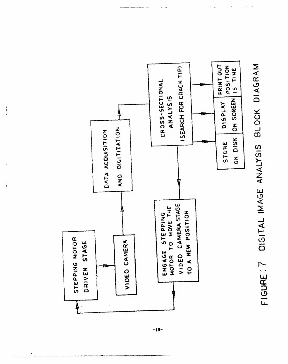
The process of data acquisition is usually repeated 2-5 times. Thus,an average picture is obtained, which is relatively free of random,hardware induced, noise. The image is digitized into 512 x 512 pixelsand light intensity of each one is evaluated with 8-bit accuracy. Thedigitized image is used for analysis of the crack-tip position.The block diagram of the developed software package is shown inFigure 7.
-17-
C
0 a:0 4X
a. U0AZ
o i 4E c
I(ZD
4~~ zr~ . ~
040U) 4
Zr 0 0
L> 0
U 0
0-18-

3.4. Soitware
3.4.1. Logic of the Automated Crack-Tip Follower (ACTIF) Software Package
Without loss of generality, let us assume that the crack is propagatingfrom the top of the screen to the bottom. In every experimental set-upsuch postionning is possible by simple rotation of the camera head.Let us set the origin of the absolute coordinate system at the locationof the tip of the crack before it started to grow.
I X
* crack* tip
The process of crack location, recording and decision on advance ofthe stepping motor is set as follows:
1) Adjust the camera head position, location, and lighting in such away that the initial crack is visible on the screen similar tothe sketch above.
2) Using the cursor, show the position of the reference scale on thescreen. This information is needed for scaling of the visualimage to its real size.
3) Enter information about the desired temporal length of the testand frequency of data acquisition.
4) Using the cursor, show the position of the crack-tip on the screen.
5) When everything is ready for a test hit (return), and process ofthe crack-tip following will be initiated.
6) The system will acquire the optical image and digitize it into512 x 512 pixels, at each location the relevant light intensitywill be acquired with 8-bit resolution, i.e. value between 0and 255 will be assigned.
7) Since the crack is growing from the top and its initial positionis known, the system will scan horizontally, starting 30 rows abovethe given crack-tip position (to ensure that we are above theactual crack-tip). The acquired light intensity along any particularrow is analyzed, and the position of the crack line is determined,since at the crack line location value of light intensity is lessthan any place around this area.
-19-

After the scan of one row is completed, the system advances tothe next row and the same process is repeated. At one instanceof time, the crack line will not be detected, since we advancedbelow position of the actual crack-tip. This will signify thecrack-tip position. The absolute coordinate and time will bestored, the system will wait for the prescribed time intervalbefore the next picture is acquired, and the whole process willbe repeated.
8) After several advances, the crack-tip will approach the lower endof the screen, i.e., it will arrive close to the boundary of theavailable optical image. At this point, the stepping motor willbe engaged and the camera head will be linearly moved by a pre-scribed distance to ensure that the crack-tip is now at the upperpart of the screen.
Assuming parallel motion of the camera head, with respect to thespecimen surface, the new position of the crack within the opticalimage can be easily calculated. On the other hand, by assumingslow rate of the crack-tip propagation and locating the positionof the crack on the screen, the two positions can be compared toone another.
In an unlikely event of a large crack advance, that occurred duringthe camera motion, the operator will be notified by a "beep" andthis event will be noted on the data file, which contains allspatial and temporal information about crack-tip history. Thus,necessary adjustment can be implemented.
9) The system will now, again, return to step 7, and this process(steps 7 and 8) will repeat itself until the prescribed time limitis achieved or the specimen will fail catastrophically.
10) In the case, where information on the applied load is availablein electronic form (analog or digital), it can also be fed intothe system, thus providing all necessary information for automatedanalysis of the fatigie test results.
Since the objective of the Phase I was limited to the demonstrationof feasibility, the software described above did not include additionalalternative approaches that are highly desirable, to insure a full-proofindustrial-environment operation. The complete software package willbe more fully developed in the Phase II of this project.
-20-

4. RESOLUTION OF THE SYSTEM
The resolution of the crack-length measuring device is important, since itaffects exponentially the precision determination of the fracture mechanic
parameters that are tested.
A purely optical observation at room temperature has virtually no resolutionlimits, since the magnification of the observing microscope can be increasedat will. A bonded sensor, such as crack-propagation gage introduces severalpotential inaccuracies:
a) The crack-tip of the sensor does not coincide with the crack-tip of the
specimen.
b) The sensor consists of grid lines that are discretely spaced.
c) The instrument used for readout of a bonded sensor has limits of resolution.
The optical method proposed here has the resolution that depends of the
objective lens used at the tip of the penetrator (See Figure 2 & 3).
a) Resolution of the Digital Image Analysis System
The full frame is resolved in 512 x 512 pixels. Selecting the magnifi-cation to observe a 6 m (Q in.) on the full-size screen, the resolutionbecomes:
6 mm/ 512 - 0.012 mm (.0005 in.).Using a 3 mm image, one can increase the resolution to:
3 mm/512 = 0.006 mm (.00025 in.).
b) Resolution of the Stage: Positionning of the Penetrator
The step motor is geared 1:1 to the lead screw, I" diameter - 20 TPI.The stepping motor controller resolves I step (400-1 steps/rev.) providingan overall position resolution:
.050 in./revolution/400 half-steps - 0.000125 in.
The stage was equipped with anti-backlash drive and 4 in. travelcapabilities.
c) Resolution of the Optical System
Two concepts of optical systems transmitting the image between the twopenetrators were tested (Figures 3 and 4). The resolution of the systemusing relay-lenses (Figure 4) is much greater than the resolution ofthe system user fiber-optic guide (Figgre 3). The fiber-opptic imageguide was constructed of 12 (12 x 10- m) fibers yielding a resolutionthat is nearly identical to the pixel resolution of the DIA system.
The overall resolution is, therefore, limited by the DIA system, and is0.00025 in., approximately four times better than the precision required,initially for set-up as a target of this feasibility study.
-21-

5. TEST RESULTS AND CONCLUSIONS
5.1. System Components
Upon completion of the system design, the components were assembled andeach individual performance verified.
Figure 9: Illustrates the Digital Image Analysis System used in thisprogram.
Figure 10: Shows the stepping-motor driven stage, with the programmableindexer. The penetrator and camera are mounted on the stage.
Figure 11: Set-up used in the furnace for verification of the performanceof optical materials at 20000 F.
Figure 12: Typical display of the crack-tip position on the monitor screen.
5.2. Test and Evaluation of the Optical System
5.2.1. Room Temperature Testing
The penetrator was assembled, for testing of both configurations, RELAY-LENS(Figure 3) and Fiber-Optic image guide (Figure 4).
Both configurations provided the desired image transmission. The relay-
lens system yielded a slightly lower transmission effficiency, due toreflection losses on each lens surface.
The QUALITY of the image transmitted by the relay-lens model was considerablyhigher. The fiber-optic guide image, when carefully focused, (See Figure 13),
(at higher magnification than used in operation), shows fiber-boundaries.
The presence of these boundaries could adversely affect the crack detectionability of the Digital Image Analysis, when used at the same magnificationlevel For this reason, we concluded that the relay-lens system should bepreferred.
5.2.2. Elevated Temperature Testing
Presently available fiber-optic guides are limited in their high-temperature
capabilities. Although several manufacturers advertise the availabilityof fused-silica fibers, not a single manufacturer was able to quote a
coherent image conduit. Two manufacturers stated that they are presentlyworking on this item and fused-silica image conduits will be available inthe near future, (probably for the Phase II program). For the relay-lens
penetrator, FUSED SILICA lenses were procured and installed as shown inFigure 3.
The assembled penetrator was installed in the high-temperature furnace inour laboratories, facing a specimen containing a naturally grown crack at20000 F. The lens-system performed flawlessly.
-22-

FIGURE 9: DIGITAL IMAGE ANALYSIS SYSTEM
FIGURE 10: MOTION CONTROL STAGE
-23-

FIGURE 11: PENETRATOR USED TO OBSERVE A SPECIMEN INSIDE THE HIGH-TEMPERATURE
FURNACE.
FIGURE 12: CRACK-TIP POSITION READOUT
-24-

110113 13: IMAGE NYMRflD3 FISS-OFTIC GUIDEt

After several 20008 F cycle, there was no visible trace of an opticalsurface degradation or lenses exposed to 20000 F, but some oxydation waspresent on all stainless steel surfaces. It is probably advisable toreplace some st. st. components by ceramics, mostly for all future testingat high temperature.
The penetrator design was fully successful in separating the CCD camerafrom the high-temperature environment. A thermocouple measuring thetemperature at the camera end yielded the following results:
Furnace Temperature Penetrator Temp. at Camera Mount
RT RT
10000 F 1100 F
20000 F 1450 F
A cut-off filter installed in front of the CCED sensor prevented theinfrared radiation from reaching the camera.
From the above test, both at room temperature and at 20000 F, it can beconcluded that the optical system can operate at 20000 F, and that theconcept of a penetrator is feasible and practical.
5.3. Testing of the Positionning Stage
To evaluate the positionning motion, the stage was computer-driven tovariouspositions, and requested to return to its "home" position. In alltests, the stage returned to the position within a fraction of a step,within a precision that exceeded our requirements. It was concluded thatthe motion control system is perfectly capable of performing the desiredtasks.
5.4. Testing of the System
The system evaluation was performed on a system that included the DigitalImage Analysis package (Figure 9) the positionning stage, with the penetratorand camera mounted on it (FigurelO) and the indexer driven by the softwaremeasuring the crack-tip position.
-26-

To assess the feasibility of the proposed method of detection of the crack-tip position using the Digital Image Analysis, and quantitatively determinethe crack progress, the following procedure was used:
a) The surface showing a crack was positioned in front of the system.
b) After the initial focusing, the area was illuminated, for best contrast.
c) The screen cursor was used to set-up the scale factor and the boundaries.
d) Using the software developed and described above, the coordinates ofthe crack-tip were measured.
e) The surface containing the crack was moved to a new position, simulatingthe crack growth. This simulated motion was used in order to comparethe change in (xy) tip-of-the crack coordinates measured by theDigital Image Analysis to the actual displacement measureed on a realscale.
f) The surface containing the crack was moved beyond the boundary set-upby the system to test the program ability of repositioning of thepenetrator to a new position.
The results of these tests showed that the software designed was performedin accordance with out expectations, in particular:
- The crack-tip position coordinates were displayed correctly, as thecrack-tip moved.
- Upon reaching the prescribed motion, the stage-driving motor was timelyinstructed to advance to its new position, within 0.001 in.
These results demonstrated the system operation, the software proficiency,and the feasibility of the concept.
5.5. Conclusions
From the test results obtained, it was possible to conclude that:
a) All the components needed to perform the targeted task were designedand tested at temperatures up to 20000 F.
b) An operational prototype, including all components, was assembled and
tested.
c) The software designed for detection of a crack-tip using Digital ImageAnalysis performed this function, demonstrating the feasibility of theconcept.
d) The research completed under Phase I has a broad significance. Theproposed NEW METHOD is of interest to researchers in government andindustry, and should be properly promoted pending Air Force release,ABSTRACTS will be mailed submitting the publication of the researchresults to:
- Society for Experimental Mechanics.- ASTM - Committee of Fracture Mechanics (E24)- BSSM - British Society for Strain Measurements- SPIE - Society of Photo-optical Instrumentation Engineering
In view of the novelty and originality of the optic, the acceptanceof the publication is virtually secured.
-27-

6. RECOMMENDATION - FUTURE RESEARCH
The results of the Phase I Research reported above proved the feasibilityof the concept, and demonstrated that fully automated system, based on theDigital Image Analysis can be designed and operated, providing a continuousmonitoring of the crack-tip position, at room or elevated temperature.
6.1. Extension of Temperature Range to 27000 F
Such a system can contain fused-silica optics, to operate at 20000 F, oremploy other readily available optical materials, such as sapphire toextend the operational temperature to approximately 30000 F.
In addition to investigation ofthe increased temperature capabilities,the future research (to be included in the Phase II objectives) shouldinclude:
6.2. Research on Methods of Absolute Position Indexing Using Digital ImageAnalysis
These methods should include usage of the specimen edge and/or referenceposition marks in the specimen, for verification of the absolute imageposition, with a feedback provision for updating of the stage "zero".
6.3. Illumination Methods
The illumination methods needed to provide a high-contrast image neededfor the accurate measuring is affected by the specimen temperature.Above 20008 F, the specimen radiation in the visible range becomes veryhigh and spectral filtering approach will be needed to enhance the crackvisibility.
6.4. Handling Methods in a Variable Temperature Loading Spectrum
The Phase I tests were conducted at room temperature and at 2000* F(constant temperature) steady state. In a variable temperature situation(ramp) specimen displacement and optics changes must be analyzed andincorporated in the Digital Image Analysis, for proper data interpretation.The research and experimental program should be included in the Phase IIresearch, suggesting procedures to deal with thermal gradients, assessingthe precision and developing proper thermal compensation methods.
6.5. Software Development
The software development appears to be the most desirable part of thefuture research. In addition to the USER FRIENDLY features, thatinclude on-the-screen instructions and help, the additional developmentsneeded are:
- Inclusion of the machine input, providing N (number of cyles), as a
control parameter.
- Graphic capabilities and output.
- Calculation of parameters.
Strainoptic intends to submit a Phase II proposal, including all of theabove topics, and additional objectives that appear desirable designobjectives.
-28-

kDATE
ILMED

![arXiv:2107.14484v1 [math.CO] 30 Jul 2021](https://static.fdokumen.com/doc/165x107/63237d4bbe5419ea700ea0c1/arxiv210714484v1-mathco-30-jul-2021.jpg)


![arXiv:2007.07430v1 [astro-ph.HE] 15 Jul 2020](https://static.fdokumen.com/doc/165x107/633337fda6138719eb0a81d1/arxiv200707430v1-astro-phhe-15-jul-2020.jpg)

![arXiv:2108.00061v1 [cs.CL] 30 Jul 2021](https://static.fdokumen.com/doc/165x107/6319d7d01e5d335f8d0b5455/arxiv210800061v1-cscl-30-jul-2021.jpg)


![arXiv:2107.07216v1 [physics.optics] 15 Jul 2021](https://static.fdokumen.com/doc/165x107/631e619b5ff22fc74506aacd/arxiv210707216v1-physicsoptics-15-jul-2021.jpg)


![arXiv:1907.02142v1 [cs.CR] 3 Jul 2019](https://static.fdokumen.com/doc/165x107/6320f1fceb38487f6b0fd715/arxiv190702142v1-cscr-3-jul-2019.jpg)

