Digital Design - UCSD CSE
25
1 CSE140L: Components and Design Techniques for Digital Systems Lab FSMs Instructor: Mohsen Imani Slides from Tajana Simunic Rosing Source: Vahid, Katz
-
Upload
khangminh22 -
Category
Documents
-
view
2 -
download
0
Transcript of Digital Design - UCSD CSE

1
CSE140L: Components and Design
Techniques for Digital Systems Lab
FSMs
Instructor: Mohsen Imani
Slides from Tajana Simunic Rosing
Source: Vahid, Katz

Hardware Description Languages
and Sequential Logic• Flip-flops
– representation of clocks - timing of state changes
– asynchronous vs. synchronous
• FSMs
– structural view (FFs separate from combinational logic)
– behavioral view (synthesis of sequencers – not in this course)

3
Controller Design
• Five step controller (FSM) design process
3.4

4
Controller Design: Laser Timer Example
• Problem: Pressing button (b)
once turns on laser for 3 clock
cycles
• Step 1: Capture the FSM
• Step 2: Create architecture
• Step 3: Encode the states
• Step 4: Minimize logic
• Step 5: Implement & testa
Combinational
logic
State register
s1 s0
n1
n0
xb
clk
FS
M
inp
uts
FS
M
ou
tpu
ts
Controller
x
b
clk
laser
patient

5
Laser Timer
• Pressing button (b) once turns on
laser for 3 clock cycles
• Step 1: Capture the FSM
3.3
Controller
x
b
clk
laser
patient
Clock here is “compressed” to
save space

6
Controller Design: Laser Timer Example
• Step 1: Capture the FSM
– Already done
• Step 2: Create architecture
– 2-bit state register (for 4 states)
– Input b, output x
– Next state signals n1, n0
• Step 3: Encode the states
– Any encoding with each state
unique will work
x=1 x=1 x=1
x=0
b
b’
01
00
10 11On2On1
Off
On3
a
Inputs: b; Outputs: x
Combinational
logic
State register
s1 s0
n1
n0
xb
clk
FS
M
inp
uts
FS
M
ou
tpu
ts

7
Controller Design: Laser Timer Example (cont)
• Step 4: Create state/excitation table
x=1 x=1 x=1
x=0
b
b’
01
00
10 11On2On1
Off
On3
Inputs: b; Outputs: x
Combinational
logic
State register
s1 s0
n1
n0
xb
clk
FSM
inp
uts F
SM
ou
tpu
ts

8
Controller Design: Laser Timer Example (cont)
• Step 5: Implement
combinational logic Combinational
logic
State register
s1 s0
n1
n0
xb
clk
FSM
inp
uts F
SM
ou
tpu
ts
x = s1 + s0
n1 = s1’s0b’ + s1’s0b + s1s0’b’ + s1s0’b
n1 = s1’s0 + s1s0’
n0 = s1’s0’b + s1s0’b’ + s1s0’b
n0 = s1’s0’b + s1s0’

9
Controller Design: Laser Timer Example (cont)
• Step 5: Implement
combinational logic (cont)
x = s1 + s0
n1 = s1’s0 + s1s0’
n0 = s1’s0’b + s1s0’
Combinational
logic
State register
s1 s0
n1
n0
xb
clk
FSM
inp
uts F
SM
ou
tpu
ts
n1
n0
s0s1
clk
Combinational Logic
State register
b
FSM inputs
x

10
Understanding the Controller’s Behavior
s0s1
b x
n1
n0
x=1 x=1 x=1b
01 10 11On2On1
Off
On3
00
0 0
0
00
0
b’
0
0
0
00
x=0
000
clk
clk
Inputs:
Outputs:
1
0
10
b
1
0
10
0
s0s1
b x
n1
n0
x=1 x=1 x=1
b’
01 10 11On2On1
Off
On3
clk
b
x
00
0 0
x=0
000
state=00 state=00
s0s1
b x
n1
n0
x=1 x=1 x=1
x=0
b
b’
01
00
10 11On2On1
Off
On3
1
0
1
1
0
00
110
clk0 1
01
state=01

Laser timer in Verilog
11
module LaserTimer(b, x, clk, rst);
input b, clk, rst;
output x;
reg x;
parameter S_Off = 2'b00,
S_On1 = 2'b01,
S_On2 = 2'b10,
S_On3 = 2'b11;
reg [1:0] currentstate;
reg [1:0] nextstate;
// state register procedure
always @(posedge rst or posedge clk)
begin
if (rst==1) // initial state
currentstate <= S_Off;
else
currentstate <= nextstate;
end
// combinational logic procedure
always @(currentstate or b)
begin
case (currentstate)
S_Off: begin
x <= 0; // laser off
if (b==0) nextstate <= S_Off;
else nextstate <= S_On1;
end
S_On1: begin
x <= 1; // laser on
nextstate <= S_On2;
end
S_On2: begin
x <= 1; // laser still on
nextstate <= S_On3;
end
S_On3: begin
x <= 1; // laser still on
nextstate <= S_Off;
end
endcase
end
endmodule // LaserTimer

FSM design example – Moore vs. Mealy
• Remove one 1 from every string of 1s on the input
1
0
0
0
11
zero[0]
one1[0]
two1s[1]
1/00/0
0/0
1/1
zero[0]
one1[0]
Moore Mealy

module reduce (clk, reset, in, out);
input clk, reset, in;
output out;
parameter zero = 2’b00;
parameter one1 = 2’b01;
parameter two1s = 2’b10;
reg out;
reg [2:1] state; // state variables
reg [2:1] next_state;
always @(posedge clk)
if (reset) state = zero;
else state = next_state;
state assignment
(easy to change,
if in one place)
Verilog FSM - Reduce 1s example
• Moore machine
1
0
0
0
11
zero[0]
one1[0]
two1s[1]

always @(in or state)
case (state)
zero:
// last input was a zero
begin
if (in) next_state = one1;
else next_state = zero;
end
one1:
// we've seen one 1
begin
if (in) next_state = two1s;
else next_state = zero;
end
two1s:
// we've seen at least 2 ones
begin
if (in) next_state = two1s;
else next_state = zero;
end
endcase
crucial to include
all signals that are
input to state determination
Moore Verilog FSM (cont’d)
note that output
depends only on state
always @(state)
case (state)
zero: out = 0;
one1: out = 0;
two1s: out = 1;
endcase
endmodule

module reduce (clk, reset, in, out);
input clk, reset, in;
output out;
reg out;
reg state; // state variables
reg next_state;
always @(posedge clk)
if (reset) state = zero;
else state = next_state;
always @(in or state)
case (state)
zero: // last input was a zero
begin
out = 0;
if (in) next_state = one;
else next_state = zero;
end
one: // we've seen one 1
if (in) begin
next_state = one; out = 1;
end else begin
next_state = zero; out = 0;
end
endcase
endmodule
Mealy Verilog FSM
1/00/0
0/0
1/1
zero[0]
one1[0]

module reduce (clk, reset, in, out);
input clk, reset, in;
output out;
reg out;
reg state; // state variables
always @(posedge clk)
if (reset) state = zero;
else
case (state)
zero: // last input was a zero
begin
out = 0;
if (in) state = one;
else state = zero;
end
one: // we've seen one 1
if (in) begin
state = one; out = 1;
end else begin
state = zero; out = 0;
end
endcase
endmodule
Synchronous Mealy Machine

highway
farm road
car sensors
Example: Traffic light controller
• Highway/farm road intersection

Traffic light controller (cont.)
• Detectors C sense the presence of cars waiting on the farm road
– with no car on farm road, light remain green in highway direction
– if vehicle on farm road, highway lights go from Green to Yellow to Red, allowing
the farm road lights to become green
– these stay green only as long as a farm road car is detected but never longer than
a set interval; after the interval expires, farm lights transition from Green to Yellow
to Red, allowing highway to return to green
– even if farm road vehicles are waiting, highway gets at least a set interval of green
• Assume you have an interval timer that generates:
– a short time pulse (TS) and
– a long time pulse (TL),
– in response to a set (ST) signal.
– TS is to be used for timing yellow lights and TL for green lights

Traffic light controller (cont.)
• inputs description outputs description
reset place FSM in initial state HG, HY, HR assert green/yellow/red highway lights
C detect vehicle on the farm road FG, FY, FR assert green/yellow/red highway lights
TS short time interval expired ST start timing a short or long interval
TL long time interval expired
• state description
HG highway green (farm road red)
HY highway yellow (farm road red)
FG farm road green (highway red)
FY farm road yellow (highway red)
Reset
TS'
TS / ST
(TL•C)'
TL•C / ST
TS'
TS / ST
(TL+C')'
TL+C' / ST
HG
FG
FYHY

Inputs Present State Next State OutputsC TL TS ST H F0 – – HG HG 0 Green Red– 0 – HG HG 0 Green Red1 1 – HG HY 1 Green Red– – 0 HY HY 0 Yellow Red– – 1 HY FG 1 Yellow Red1 0 – FG FG 0 Red Green0 – – FG FY 1 Red Green– 1 – FG FY 1 Red Green– – 0 FY FY 0 Red Yellow– – 1 FY HG 1 Red Yellow
SA1: HG = 00 HY = 01 FG = 11 FY = 10SA2: HG = 00 HY = 10 FG = 01 FY = 11SA3: HG = 0001 HY = 0010 FG = 0100 FY = 1000 (one-hot)
output encoding – similar problem to state assignment(Green = 00, Yellow = 01, Red = 10)
Traffic light controller (cont.)
• Generate state table with symbolic states
• Consider state assignments

module FSM(HR, HY, HG, FR, FY, FG, ST, TS, TL, C, reset, Clk);
output HR;
output HY;
output HG;
output FR;
output FY;
output FG;
output ST;
input TS;
input TL;
input C;
input reset;
input Clk;
reg [6:1] state;
reg ST;
parameter highwaygreen = 6'b001100;
parameter highwayyellow = 6'b010100;
parameter farmroadgreen = 6'b100001;
parameter farmroadyellow = 6'b100010;
assign HR = state[6];
assign HY = state[5];
assign HG = state[4];
assign FR = state[3];
assign FY = state[2];
assign FG = state[1];
specify state bits and codes for each state as well as connections to outputs
Traffic light controller FSM
• Specification of inputs, outputs, and state elements

initial begin state = highwaygreen; ST = 0; end
always @(posedge Clk)
begin
if (reset)
begin state = highwaygreen; ST = 1; end
else
begin
ST = 0;
case (state)
highwaygreen:
if (TL & C) begin state = highwayyellow; ST = 1; end
highwayyellow:
if (TS) begin state = farmroadgreen; ST = 1; end
farmroadgreen:
if (TL | !C) begin state = farmroadyellow; ST = 1; end
farmroadyellow:
if (TS) begin state = highwaygreen; ST = 1; end
endcase
end
end
endmodule
Traffic light controller FSM
case statementtriggerred byclock edge

module Timer(TS, TL, ST, Clk);
output TS;
output TL;
input ST;
input Clk;
integer value;
assign TS = (value >= 4); // 5 cycles after reset
assign TL = (value >= 14); // 15 cycles after reset
always @(posedge ST) value = 0; // async reset
always @(posedge Clk) value = value + 1;
endmodule
Timer FSM for traffic light controller
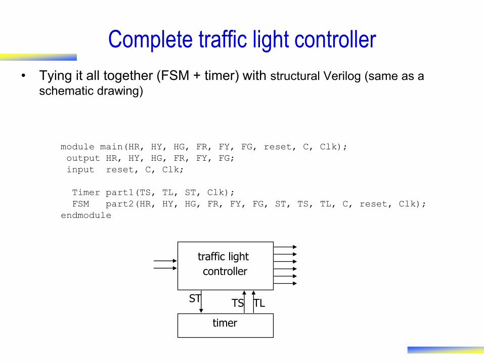
module main(HR, HY, HG, FR, FY, FG, reset, C, Clk);
output HR, HY, HG, FR, FY, FG;
input reset, C, Clk;
Timer part1(TS, TL, ST, Clk);
FSM part2(HR, HY, HG, FR, FY, FG, ST, TS, TL, C, reset, Clk);
endmodule
Complete traffic light controller
• Tying it all together (FSM + timer) with structural Verilog (same as a
schematic drawing)
traffic light
controller
timer
TLTSST

Finite state machines summary
• Models for representing sequential circuits
– abstraction of sequential elements
– finite state machines and their state diagrams
– inputs/outputs
– Mealy, Moore, and synchronous Mealy machines
• Finite state machine design procedure
– deriving state diagram
– deriving state transition table
– determining next state and output functions
– implementing combinational logic
• Hardware description languages
– Use good coding style
– Communicating FSMs