Die casting present and future in automotive applications
150
Alexandra Cheșa, BSc Die Casting Technology – Present and Future in Automotive Applications Master’s thesis to achieve the academic degree of Diplom-Ingenieur Master’s degree program: Production Science and Management Submitted to Graz University of Technology Supervisor Associate Prof. Dr. Mario Hirz Institute of Automotive Engineering Graz, June 2019
-
Upload
khangminh22 -
Category
Documents
-
view
0 -
download
0
Transcript of Die casting present and future in automotive applications

Alexandra Cheșa, BSc
Die Casting Technology – Present and Future in Automotive Applications
Master’s thesis
to achieve the academic degree of
Diplom-Ingenieur
Master’s degree program: Production Science and Management
Submitted to
Graz University of Technology
Supervisor
Associate Prof. Dr. Mario Hirz
Institute of Automotive Engineering
Graz, June 2019

II
Affidavit
I declare that I have authored this thesis independently, that I have not used other than the declared sources/resources, and that I have explicitly indicated all material which has been quoted either literally or by content from the sources used. The text document uploaded to TUGRAZonline is identical to the present master‘s thesis dissertation.
…………………………… ….…………………………………………… Date Signature

III
Acknowledgement
I would like to thank my thesis supervisor Associate Prof. Dr. Mario Hirz from the Institute of Automotive Engineering at Graz University of Technology. The door to his office was always open whenever I ran into a trouble spot or had questions regarding my research or the writing of the thesis. He consistently allowed this paper to be my own work, but steered me in the right direction whenever he considered I needed it.
I would also like to thank the professors of Production Science and Management who taught me so much during the master program. Due to their passionate dedication I was able to successfully finish this chapter of my life, becoming the professional I am today.
I would also like to acknowledge every single person that is part of the company Zatorcal for sharing all their knowledge with me, for considering me part of their family. I am gratefully indebted to Zatorcal management board for their support in finishing my studies and for helping me grow by their side.
Finally, I must express my very profound gratitude to my family, especially to my parents who made me the person I am today and to my life partner for providing me with unfailing support and continuous encouragement throughout my years of study and through the process of researching and writing this thesis. This accomplishment would not have been possible without them. From the bottom of my heart, thank you!
Alexandra Cheșa
IV
Abstract
High-pressure die-casting (HPDC) is a technology that is proper for high production rates, being used as the main manufacturing process in different industrial fields. Nowadays, about 50% of the world production of light metal castings is obtained through this technology.
Due to the actual preoccupation for the environment, a need for updating the actual technologies and materials to environment-friendly technologies and materials has been created. Since it’s not enough to only develop ecological technologies, a deeper study regarding the replacement of actual used materials has been performed.
An overview of the actual status of HPDC technology is described in the present work, where both critical aspects and potential advantages are highlighted; new technologies and materials are considered with focus on the new requirements of environment-friendly cars of the future in terms of new design and advanced hardware capable of providing autonomous driving capabilities in the future.
Particular attention is given to the finishing of the parts and the quality requirements of car manufacturers, cost saving potentials through improvements and new technologies that could substitute the present ones.
The purpose of this research is to also emphasize the most relevant challenges for the Die Casting Industry, such as: reducing scrap rates and achieving zero-defect productions, reacting in real time to blocking points, reaching the suitable variables and continuous process optimization, lean manufacturing, continuous improvement and introduction of R&D tasks. Therefore, at the end, an efficient approach to HPDC will be concluded and strategies to exploit its potential will be introduced.
V
Kurzfassung
Hochdruck-Druckguss (HPDC) ist eine Technologie, die für hohe Produktionsraten geeignet ist und als Hauptproduktionsprozess in verschiedenen Industriebereichen eingesetzt wird. Heute werden etwa 50% der weltweiten Produktion von Leichtmetallguss durch diese Technologie gewonnen.
Aufgrund der laufend höheren Anforderungen bezüglich der Umweltverträglichkeit der Produktionstechnologien besteht ein Bedarf zur Verbesserung der aktuellen Technologien und Materialien. Da es nicht ausreicht, ökologische Technologien nur zu entwickeln, wurde eine vertiefte Studie über das Potenzial für den Austausch von tatsächlich verwendeten Materialien durchgeführt.
Ein Überblick über den aktuellen Stand der HPDC-Technologie wird in der vorliegenden Arbeit beschrieben, in der sowohl kritische Aspekte als auch mögliche Vorteile hervorgehoben warden. Neue Technologien und Materialien werden mit dem Fokus auf die neuen Anforderungen an umweltfreundliche Autos der Zukunft in Bezug auf neues Design und fortschrittliche Hardware betrachtet; zusätzlich werden potenzielle Anwendungsfälle für Komponenten und Module für autonome Fahrzeuge erarbeitet.
Besonderes Augenmerk wird auf die Veredelung der Teile und die Qualitätsanforderungen der Autohersteller gelegt, unter Berücksichtigung potenzieller Kosteneinsparungen durch Verbesserungen und neue Technologien.
Ziel dieser Forschung ist es, die wichtigsten Herausforderungen für die Gießindustrie hervorzuheben, wie zum Beispiel die Reduzierung der Schrottpreise und das Erreichen von Null-Fehler-Produktionen, die Möglichkeit in Echtzeit auf Änderungsanforderungen zu reagieren. Des Weiteren müssen Prozesse entwickelt werden, welche eine kontinuierliche Prozessoptimierung, schlanke Fertigung, kontinuierliche Verbesserung sowie die Einführung von F & E-Aufgaben ermöglichen. In diesem Zusammenhang werden am Ende der Arbeit ein effizienter Ansatz für HPDC vorgestellt und Strategien zur Nutzung des Potenzials diskutiert.

VI
Table of Content Acknowledgement........................................................................................................ III
Abstract ........................................................................................................................ IV
Kurzfassung ................................................................................................................. V
1 Introduction ............................................................................................................ 2
1.1 Objectives ......................................................................................................... 2
1.2 Structure of the thesis ....................................................................................... 3
2 An introduction to die casting .............................................................................. 4
2.1 Overview ........................................................................................................... 4
2.2 Process ............................................................................................................. 5
2.3 Equipment ......................................................................................................... 6
2.3.1 The ejector die half .................................................................................... 6
2.3.2 The cover die half ...................................................................................... 7
2.3.1 Hot-chamber machines .............................................................................. 9
2.3.2 Cold-chamber machines .......................................................................... 10
2.4 Die-casting - advantage and disadvantages ................................................... 11
2.4.1 Advantages of high pressure die casting ................................................. 11
2.4.2 Disadvantages of high pressure die casting ............................................ 12
2.4.3 Potential alternative production technologies ........................................... 12
2.5 Materials – alloys used in die casting .............................................................. 14
3 Die casting - present ............................................................................................ 18
3.1 A fingerprint of the company ........................................................................... 18
3.2 Optimization of actual processes in the company ........................................... 21
3.2.1 Artificial vision for quality check ............................................................... 22
3.2.2 Monitoring of die casting tools with thermal imaging cameras ................. 23
3.2.3 Internationalization in die casting ............................................................. 25
3.2.4 Prototype manufacturing in house ........................................................... 26
3.2.5 Other possible improvements .................................................................. 30
3.2.6 Vacuum assisted die casting ................................................................... 31
3.2.7 Die spraying process ............................................................................... 32

VII
3.3 Materials now .................................................................................................. 33
3.3.1 Steel – the material of the present ........................................................... 33
3.3.1 Typically used materials in die casting and their main properties and applications ............................................................................................................ 34
3.3.2 Different alloys properties and the die casting process ............................ 39
3.3.3 Aluminum alloys and their benefits .......................................................... 41
3.3.4 Magnesium alloys .................................................................................... 42
3.3.5 Aluminum vs. magnesium alloys .............................................................. 44
3.3.6 Zinc vs. magnesium alloys ....................................................................... 44
3.3.7 Zinc and zinc-aluminum alloys ................................................................. 45
3.3.8 Aluminum vs. zinc alloys .......................................................................... 45
3.3.9 Determining alloy and casting costs ........................................................ 46
4 Vehicles of the future ........................................................................................... 47
4.1 Electromobility ................................................................................................. 48
4.1.1 Electromobility: definition, vehicles and future ......................................... 49
4.1.2 Types of electric drives ............................................................................ 50
4.1.3 Differences between electric engine and gasoline engine ....................... 51
4.1.4 Advantages and disadvantages of electric mobility ................................. 52
4.1.5 Electromobility - current market data ....................................................... 53
4.1.6 E-cars - energy storage technology ......................................................... 54
4.1.7 Charging systems for electric cars ........................................................... 55
4.1.8 Reaction of automotive manufacturers towards e-mobility....................... 56
4.1.9 The future of die casting influenced by electromobility ............................ 56
4.2 Autonomous cars ............................................................................................ 58
4.2.1 ADAS - The pre-step technology to autonomous driving ......................... 58
4.2.2 The technology behind autonomous cars ................................................ 59
4.2.3 Advantages, disadvantages and challenges of autonomous cars ........... 64
4.2.4 The global market of autonomous vehicles in 2040 ................................. 65
4.2.5 The six levels of autonomous driving ....................................................... 66
5 Die casting – future .............................................................................................. 68

VIII
5.1 Development of die casting ............................................................................. 68
5.2 Radical change in die casting foundries .......................................................... 68
5.3 Electromobility relies on foundries .................................................................. 69
5.3.1 Electrification of the powertrain ................................................................ 71
5.3.2 Lightweight structures – key factors ......................................................... 72
5.3.3 Electrical strip – a core material ............................................................... 72
5.4 The influence of electromobility ....................................................................... 73
5.4.1 Overview .................................................................................................. 73
5.4.2 Forecast of electromobility ....................................................................... 74
5.4.3 Global market .......................................................................................... 75
5.5 Technological advances ................................................................................. 76
5.6 Changes in foundries product portfolio ........................................................... 77
6 New business cases ............................................................................................ 80
6.1 Effects of electromobility on vehicle architecture ............................................ 80
6.2 Motor housings made from cast aluminum ..................................................... 82
6.3 New drive concepts with formed steel and die-casting ................................... 83
6.4 Vehicles with cameras instead of typical side-view mirrors ............................. 83
6.5 KERS .............................................................................................................. 87
6.6 Sensor housing ............................................................................................... 90
6.7 Cameras ......................................................................................................... 91
6.8 Radar .............................................................................................................. 93
6.9 Lidar ................................................................................................................ 94
7 Alternative technologies to die casting ............................................................. 95
7.1 Alternatives to injection molding ...................................................................... 95
7.2 Metal casting processes [55] ........................................................................... 100
7.3 Hybrid additive manufacturing ....................................................................... 101
7.4 Additive manufacturing ................................................................................. 102
7.4.1 Printed sand molds for metal casting ..................................................... 103
7.4.2 High-precision melt-off models for investment casting ........................... 104
7.5 3D metal printing ........................................................................................... 105

IX
7.5.1 Powder bed welding .............................................................................. 106
7.5.2 Selective laser melting (SLM) ................................................................ 106
7.5.3 EBM - Melting with an electron beam .................................................... 106
7.5.4 LMD - Laser deposition welding ............................................................. 107
7.5.5 MPA ....................................................................................................... 107
7.6 Overmolding .................................................................................................. 107
7.6.1 Insert molding ........................................................................................ 108
7.6.2 Two-shot molding .................................................................................. 108
7.6.3 Co-injection molding .............................................................................. 108
7.6.4 Macromelt molding ................................................................................ 108
8 Materials of the future ........................................................................................ 110
8.1 Material requirements in automotive design.................................................. 110
8.1.1 Light weight ............................................................................................ 110
8.1.2 Economic effectiveness ......................................................................... 112
8.1.3 Safety..................................................................................................... 113
8.1.4 Recycling ............................................................................................... 113
8.2 New materials for automotive industry .......................................................... 113
8.2.1 Aluminum ............................................................................................... 113
8.2.2 Magnesium as a lightweight material ..................................................... 117
8.2.3 Advanced composite materials .............................................................. 119
8.2.4 Glass-fiber composites .......................................................................... 119
8.2.5 Graphene ............................................................................................... 119
8.2.6 Aerogel .................................................................................................. 119
8.2.7 Transparent aluminum ........................................................................... 119
8.2.8 Carbon-fiber epoxy composite ............................................................... 120
8.2.9 Carbon fiber ........................................................................................... 120
8.3 Effects of electromobility on materials ........................................................... 123
8.4 The importance of lightweight materials in automotive industry .................... 124
9 Conclusion and outlook .................................................................................... 129
References ................................................................................................................. 130

X
List of Tables ............................................................................................................. 140
List of Abbreviations ................................................................................................. 141

Die casting technology – Present and future in automotive applications
2
1 Introduction
The global automotive industry is facing 4 changes today, connected cars, electrification of the propulsion systems, autonomous driving technologies and car sharing. Automotive industry suppliers can see them as opportunities or threats. Each challenge is potentially existential to car manufacturers who operate in the automotive sector, which might influence the supply lines by cumulative advances typically deployed by tier-1 and tier-2 automotive sub-system suppliers. This thesis focuses on the traditional manufacturing method of die casting technology as it is in the present and where it might stand in the future.
1.1 Objectives
The objective of this research is to analyze tendencies in automotive industry and emphasize how they might influence the die casting industry and where the corresponding market is heading to.
Die casting foundries might benefit from the study by being prepared to face the new challenges. New technologies, new materials and new requirements for the products might bring significant changes in the present die casting production strategy.

Die casting technology – Present and future in automotive applications
3
1.2 Structure of the thesis
The thesis is structured in 2 main parts. The first one deals with an analysis of die casting as it is used in the present, taking as a reference the company Zatorcal [1], a tier 2 die casting organization, providing parts for tier 1 companies. Out of this analysis, some optimization proposals are realized in order to obtain cost improvement benefits and promote digitalization and self-assessment in production.
The second part of the thesis deals with new challenges that this technology might encounter. The rising speed of technological progress and technology adoption imply new specifications in the cars of the future. The transition to electric drivetrain systems and improvements that have to deal with aerodynamics, self-driving functions and security in terms of design, new technologies and new materials requires changes in actual technologies.
Since the core products of the mentioned company are mirror holders, this study will reveal the position of the company in the near future taking into consideration the new possible design of external mirrors, emphasizing the landscape of the criticality of products and the risk of the core products to disappear. Therefore, a need to react quickly to this demand has been created.
At the end of the thesis, the reader will have a clear view regarding die casting technology, about the advantages and disadvantages that this technology implies and the changes it might face in the near future, during changing times when the automobile industry is in a continuous development and more and more car manufacturers embrace new design, technology and systems.

Die casting technology – Present and future in automotive applications
4
2 An introduction to die casting
Die casting technology dates back to the mid 1800´s. It is one of the most creative and adaptable metalworking processes. It provides endless varieties of products used in various industries. New technologies and innovations keep this manufacturing process moving forward.
High-pressure die casting is the process, in which the molten metal is injected into the mould cavity under very high pressure up to 30,000 psi (200 MPa), in order to manufacture high precision die cast products.
The steel mould used in the die casting process is called a die and it is designed to cast engineered shapes and complex features with great accuracy and quality surfaces. It has a limited lifetime before it is deteriorated and needs corrections or replacement.
Global automotive die-casting parts market is expected to highly raise by the year 2026. The market growth is fueled by factors such as favorable government initiatives, the growing market for lightweight components and technological advancements. [2]
The following exemplary parts are manufactured by die casting method: automotive connecting rods, pistons, cylinder beds, electronic enclosures, toys and plumbing fittings. Therefore, it is a highly productive method for producing parts with high surface quality and low dimensional tolerances.
Die casting is a highly used technology among industrial manufacturers due to the good mechanical properties that it can achieve. Here are a few advantages to highlight: high-speed production rates can be achieved, which automatically implies an economical process, dimensional accuracy can be reached, parts with high quality surface finish, complex shaped parts with thin walls and different geometries or small sized parts are suitable for casting.
2.1 Overview
High pressure die casting is a metal casting process that injects molten metal under high pressure into the mold cavities. The cavity is built from 2 hardened tool steel dies previously machined into the desired shape. The casting equipment represents a large investment, therefore, die casting is an economical process only if used for high volume production.
Since the manufacturing process using die casting technology is relatively simple, it is able to keep the cost per item low. Die casting produces more castings than any other

Die casting technology – Present and future in automotive applications
5
castings, being a manufacturing process suitable for small to medium sized castings in large quantities.
Die casted parts are used because of their relatively good surface finish and dimensional consistency.
Most die castings are made from non-ferrous metals, specifically zinc, copper, aluminum, magnesium, lead, pewter and tin based alloys. Depending on the type of metal being cast, a hot- or cold-chamber machine is used.
2.2 Process
The following are the four steps in traditional die casting, also known as high-pressure die casting, these are also the basis for any of the die casting variations: die preparation, filling, ejection, and shakeout. The dies are prepared by spraying the mold cavity with lubricant. The lubricant both helps control the temperature of the die and it also assists in the removal of the casting. The dies are then closed and molten metal is injected into the dies under high pressure; typically between 10 and 175 megapascals (1,500 and 25,400 psi). Once the mold cavity is filled, the pressure is maintained until the casting solidifies. The dies are then opened and the shot (shots are different from castings because there can be multiple cavities in a die, yielding multiple castings per shot) is ejected by the ejector pins. Finally, the shakeout involves separating the scrap, which includes the gate, runners, sprues and flash, from the shot. This is often done using a special trim die in a power press or hydraulic press. Other methods of shaking out include sawing and grinding. A less labor-intensive method is to tumble shots if gates are thin and easily broken; separation of gates from finished parts must follow. This scrap is recycled by re-melting it. The yield is approximately 67%.
The high-pressure injection leads to a quick fill of the die, which is required so the entire cavity fills before any part of the casting solidifies. In this way, discontinuities are avoided, even if the shape requires difficult-to-fill thin sections. This creates the problem of air entrapment, because when the mold is filled quickly there is little time for the air to escape. This problem is minimized by including vents along the parting lines, however, even in a highly refined process there might still be some porosity in the center of the casting.
Most die casters perform other secondary operations to produce features not readily castable, such as tapping a hole, polishing, plating, buffing, or painting.

Die casting technology – Present and future in automotive applications
6
2.3 Equipment
The equipment involved in die casting process is mainly represented by the die halves. Apart from the dies, which in some exceptional die casting processes can be more than two, the tool is also built of slides, which accommodate undercuts in a die cast part, the interchangeable cores that make the different size holes in the die casted parts and the ejectors pins that push the part out of the mould.
2.3.1 The ejector die half
Figure 1. Die casting tool – the ejector die half [3]
Die casting process involves a tool that is mainly made of two dies; one is called the "cover die half" or the fixed part of the tool and the other the "ejector die half" or the mobile part of the tool. Where they meet is called the parting line. The cover die contains the sprue (for hot-chamber machines) or shot hole (for cold-chamber machines), which allows the molten metal to flow into the dies; this feature matches up with the injector nozzle on the hot-chamber machines or the shot chamber in the cold-chamber machines. The ejector die contains the ejector pins and usually the runner, which is the path from the sprue or shot hole to the mold cavity. The cover die is secured to the stationary, or front, platen of the casting machine, while the ejector die is attached to the movable platen. The mold cavity is cut into two cavity inserts, which are separate pieces that can be replaced relatively easily and bolt into the die halves.
At the end of the cycle, the finished casting will slide off the cover half of the die and stay in the ejector half as the dies are opened. This assures that the casting will be ejected

Die casting technology – Present and future in automotive applications
7
every cycle because the ejector half contains the ejector pins to push the casting out of that die half. The ejector pins are driven by an ejector pin plate, which accurately drives all of the pins at the same time and with the same force, so that the casting is not damaged. The ejector pin plate also retracts the pins after ejecting the casting to prepare for the next shot. There must be enough ejector pins to keep the overall force on each pin low, because the casting is still hot and can be damaged by excessive force. Since the pins might leave a mark, they are designed to be located in places that do not interfere with the rest of the final assembly, so that they do not hamper the castings purpose.
2.3.2 The cover die half
Figure 2. Die casting tool - the cover die half [3]
Cores and slides are other components that make the die. Cores are components used to produce holes, openings or to create different types of details. There are three types of cores: fixed, movable, and loose. Fixed cores are ones that are oriented parallel to the pull direction of the dies (i.e. the direction the dies open), therefore they are fixed, or permanently attached to the die. Movable cores are ones that are oriented in any other way than parallel to the pull direction. These cores must be removed from the die cavity after the shot solidifies, but before the dies open, using a separate mechanism. Slides are similar to movable cores, except they are used to form undercut surfaces. The use of movable cores and slides greatly increases the cost of the dies. Loose cores, also called pick-outs, are used to cast intricate features, such as threaded holes. These loose cores are inserted into the die by hand before each cycle and then ejected with the part at the end of the cycle. The core then must be removed by hand. Loose cores are the most expensive type of core, because of the extra labor and increased cycle time. Other
Die casting technology – Present and future in automotive applications
8
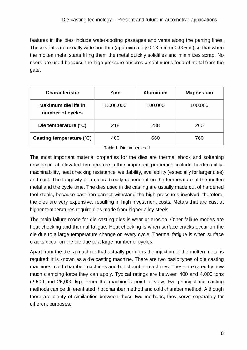
features in the dies include water-cooling passages and vents along the parting lines. These vents are usually wide and thin (approximately 0.13 mm or 0.005 in) so that when the molten metal starts filling them the metal quickly solidifies and minimizes scrap. No risers are used because the high pressure ensures a continuous feed of metal from the gate.
Characteristic Zinc Aluminum Magnesium
Maximum die life in number of cycles
1.000.000 100.000 100.000
Die temperature (ºC) 218 288 260
Casting temperature (ºC) 400 660 760
Table 1. Die properties [1]
The most important material properties for the dies are thermal shock and softening resistance at elevated temperature; other important properties include hardenability, machinability, heat checking resistance, weldability, availability (especially for larger dies) and cost. The longevity of a die is directly dependent on the temperature of the molten metal and the cycle time. The dies used in die casting are usually made out of hardened tool steels, because cast iron cannot withstand the high pressures involved, therefore, the dies are very expensive, resulting in high investment costs. Metals that are cast at higher temperatures require dies made from higher alloy steels.
The main failure mode for die casting dies is wear or erosion. Other failure modes are heat checking and thermal fatigue. Heat checking is when surface cracks occur on the die due to a large temperature change on every cycle. Thermal fatigue is when surface cracks occur on the die due to a large number of cycles.
Apart from the die, a machine that actually performs the injection of the molten metal is required; it is known as a die casting machine. There are two basic types of die casting machines: cold-chamber machines and hot-chamber machines. These are rated by how much clamping force they can apply. Typical ratings are between 400 and 4,000 tons (2,500 and 25,000 kg). From the machine´s point of view, two principal die casting methods can be differentiated: hot chamber method and cold chamber method. Although there are plenty of similarities between these two methods, they serve separately for different purposes.

Die casting technology – Present and future in automotive applications
9
2.3.1 Hot-chamber machines
Hot-chamber machines, also known as gooseneck machines, rely upon a pool of molten metal to feed the die. At the beginning of the cycle the piston of the machine is retracted, which allows the molten metal to fill the "gooseneck". The pneumatic or hydraulic powered piston then forces this metal out of the gooseneck into the die. The advantages of this system include fast cycle times (approximately 15 cycles a minute) and the convenience of melting the metal in the casting machine. The disadvantages of this system are that high-melting point metals cannot be utilized and aluminum cannot be used because it picks up some of the iron while in the molten pool. Due to this, hot-chamber machines are primarily used with zinc, tin, and lead based alloys.
Hot chamber die-casting requires the usage of alloys with low melting temperatures such as zinc and some magnesium alloys. High melting alloys would lead to damage to the gooseneck, nozzle and other components.
The fixed die, which is also known as the cover die, is placed on a large plate also known as a stationary platen and gets aligned with the nozzle of the gooseneck. The movable die, which is also placed on another large plate performs the function of ejecting when sliding along the tie bars. The picture below states as an explanation for the functionality of a hot chamber die casting machine.
Figure 3. Functionality of a hot chamber die casting machine [4]
The hot chamber process consists of translating the metal from the open holding pot to the furnace in order to melt it to the specified temperature. In this type of machines, it is crucible that the pressure chamber (cylinder) and the plunger are submerged in the molten metal in the pot. The plunger goes up, allowing the molten metal to flow into the shot chamber and fill the cylinder space. At this stage, the die is completely closed. As the plunger goes down, due to the high pressure ranging from 1000 to 5000 psi, it forces the material to flow into the die cavity through a gooseneck. After the die is completely

Die casting technology – Present and future in automotive applications
10
filled with the molten metal, the machine pushes the moving platen towards the cover die and holds it closed with great pressure until the injection is completed. The plunger is held in the ´down´ position, under pressure until the solidification is completed and the casting cools off. Then, after solidification, the die opens and the plunger retracts, allowing the melt residuals to return through the gooseneck back to the pot. The casting remains in the die part equipped with ejectors. At this point, the casting can be either manually removed or pushed off from the machine by the ejector die with its ejector pins. The die halves are released and the cycle continues repeatedly.
2.3.2 Cold-chamber machines
One remarkable difference when compared to hot chamber consists of the fact that cold chamber machines function in a horizontal orientation and do not have the gooseneck. A principal scheme of a cold chamber die-casting machine is shown below, in the picture.
Figure 4. A schematic of a cold-chamber die casting machine [4]
Cold chamber die-casting requires the usage of alloys with high melting temperatures like aluminum, some magnesium alloys, copper alloys and zinc alloys with a large composition of aluminum.
The process of these machines starts with melting the metal in a separate furnace. In contrast to hot chamber die-casting, where molten metal is pumped into the machine, in cold chamber die-casting, a precise amount of molten metal is transported from the furnace to the cold-chamber machine through the pouring hole and into the unheated shot chamber, also called injection cylinder. When the pressure chamber is filled, the plunger starts moving and by building up a pressure ranging from 2000 to 20000 psi, it forces the molten metal to flow through the shot chamber (sprue) into the die cavity.
The plunger holds the pressure and after solidification, it returns to its initial position. A new quantity of molten metal can now fill the pressure chamber. The die opens and the ejector pins remove the casting from the die. The casting cycle starts over again.
The biggest disadvantage this system presents is the slower cycle time due to the need to transfer the molten metal from the furnace to the cold-chamber machine.

Die casting technology – Present and future in automotive applications
11
2.4 Die-casting - advantage and disadvantages
2.4.1 Advantages of high pressure die casting
Compared to plastic injection molding, die casting produces stronger parts with closer tolerances that have greater stability and durability. Die cast parts also have greater resistance to temperature extremes and superior electrical properties.
Since they are not components that are manufactured by being joined or welded together, die casted parts are as strong as the alloy that makes them, rather than the actual joining process. Another benefit is that parts that have been die cast can have many finishing techniques and surfaces, and can easily be designed to have a certain desired appearance.
Sand casting is another technique that is usually contemplated for manufacturing parts. Sand cast parts typically have a rough surface appearance, surface variations and impurities. Compared to sand casting, die casting is able to produce parts that have thinner walls, closer dimensional tolerances and smoother surfaces. Die casting process is also much more economical than sand casting (for large quantities), the production is faster, finishing costs are lower, and significant overall savings are seen.
While there are always certain exceptions for specific applications, the distinct advantages of die casting over other processes are specified below.
High-speed production
Die casting is able to produce complex shapes within the required tolerances. It reduces or even eliminates secondary machining operations. It can achieve rapid production rates; therefore, millions of identical castings can be produced before sub-processes or additional tooling are required.
Dimensional accuracy and stability
Die casting outputs parts that have excellent dimensional accuracy and stability with close tolerances and of high durability. They are also resistant to heat (depending on the material).
Strength and weight
Due to the fact that parts from die casting do not consist of separate welded parts, they are stronger than plastic injected moldings. Moreover, the strength is that of the alloy rather than the joining process. Also, the thin walls castings (up to approximately 0.75 mm) are lighter and stronger compared to those produced through other production methods such as sand and permanent mold casting.

Die casting technology – Present and future in automotive applications
12
Multiple finishing techniques
Die casted parts have a smooth or textured surface (Ra 1-2.5 micrometers) which can easily get plated or finished.
Simplified Assembly
Bosses or studs represent some of the integral fastening elements that can be produced through die casting. External threads or inserts, heating elements and high strength bearing surfaces can also be cast-in.
2.4.2 Disadvantages of high pressure die casting
High capital costs
The main disadvantage of high-pressure die casting is the high investment cost. Due to the required equipment, such as the injection machines, the dies and the related components such as trimming tools reach high costs, compared to other manufacturing processes. Implicitly, in order to be considered an economical process, it requires a large production volume. Apart from the die, a machine that actually performs the injection of the molten metal is required; it is known as a die casting machine.
Process limitations
The process is limited to high-fluidity metals. It is not applicable for high melting point metals and alloys. (e.g. steels). Part weights can only be between 30 grams and 10 kg and geometrically large parts cannot be casted.
Defects in the final surface
The heat causes gas in the pores to expand and creates micro-cracks inside the part and exfoliation on the surface. Gas may be stuck in the parts. Therefore, in some cases the final part might present a small amount of porosity.
Large lead times
Another negative point to highlight is the large lead-time needed for the design definition, tool construction, trials, adjustments and corrections.
2.4.3 Potential alternative production technologies
In the past years, metal parts were produced with different technologies. Among them can be listed: additive manufacturing, 5-axis high speed CNC machining (computer numerically controlled), metal stamping.
Additive manufacturing

Die casting technology – Present and future in automotive applications
13
Additive manufacturing, or 3D printing is currently a cost effect way to produce high complexity and small batch size parts. It replaced conventional manufacturing and design processes.
Among the advantages of additive manufacturing are weight reduction, functional customization, part consolidation, through personalization and aesthetics.
Compared to die casting, additive manufacturing presents geometrical freedom that allows the production of optimized components for their functionality. The disadvantages, however, consist in the production costs. They need to be closely analysed to assess the economical convenience of additive manufacturing with respect to high pressure die casting technology. At a first glance, the production volume for which additive manufacturing is cost-effective is from prototypes to small batch production, whereas die casting is cost-effective in large serial production.
Recent developments in additive manufacturing technologies for the production of metal parts make it attractive to high technology industries. It has the potential to be considered one of the technologies of the future, especially because it´s suitable for producing plastic, metal, ceramic or composite parts.
Machining
CNC machining is one of the most precise manufacturing method in which tools and machinery movements are dictated by pre-programmed computer software. It is the process of carving a piece of raw material into a desired shape.
The CNC machining process can be used to control a range of complex machinery, from grinders and lathes to mills and routers. Three-dimensional cutting tasks can be accomplished in a single set of prompts.
Compared to die casting, CNC machining is a highly adaptable process. Equipment cost and maintenance are higher, but cost of running operations are much lower. In terms of production batches cost effectiveness, machining is one of the most expensive for mass production, due to the large time that it requires. It has a long-term useful life, though. In contrast to die casting, labor costs are higher due to the fact that CNC machining requires skilled operators. The similarity to die casting stands in the high removal amount of material made up with recycling return.
Stamping
Stamping is a manufacturing method that deals with all forms of sheet metal work. These processes include stamping, bending forming and coining. In the metal stamping process, a sheet metal is automatically fed into a hydraulically or mechanically driven press which

Die casting technology – Present and future in automotive applications
14
shapes the metal. It is an efficient manufacturing method commonly used to make production parts.
Metal stamping and die casting are two extremely different metal forming processes. Die casting utilizes ingots or billets, while stamping requires sheet metal blanks or coils; metal is heated past its melting point to be die cast, while stamping is almost always a cold working process.
The two different processes also have different strengths and weaknesses. Die casting is capable of producing parts with extremely complex geometries. Metal stamping is more economical when it is used for parts with simpler geometries. Stamping is capable of producing very complex parts, but at a cost: the more complex a part is, the more components the tool and die require – the more tool and die components there are, the higher tooling costs become.
Metal stamping can be performed on ferrous and non-ferrous materials alike, while die casting is generally limited to only non-ferrous materials. While careful design can minimize it, stamping creates a large amount of scrap material – it can be recycled, but the material costs include the cost for material that isn’t directly used. Die casting generates a much lower volume of scrap and the scrap that is produced is more easily recyclable, simply being turned to the holding pot and allowed to re-melt. [5]
Extrusion
Extrusion is the process of manufacturing parts of either plastic, metal or rubber that have a fixed cross-sectional profile, such as pipes. Extruded parts are made by squeezing hot raw material through a custom cross-section die.
The two main advantages of this process over die casting method are its ability to create very complex cross-sections, and to work materials that are brittle, because the material only encounters compressive and shear stresses. It also forms parts with an excellent surface finish. Due to these particularities, extrusion is a manufacturing method that will still be used in the future.
2.5 Materials – alloys used in die casting
Die casting moulds are usually constructed from hardened steel and they are often the most expensive component in a die casting machine. These moulds can handle a range of different alloy families with varying results, but die casting is generally most effective on metals with low fusing temperatures. For this reason, the common die casting alloys fall into a handful of categories based on their composition and material properties.

Die casting technology – Present and future in automotive applications
15
Zinc alloys
Zinc-based materials are relatively easy to die cast, and respond well to the die moulding process. These materials are comprised of multiple metals in specific ratios. For example, a typical zinc-based die casting workpiece consists of 86 percent zinc, 4 to 7 percent copper, and 7 to 10 percent tin. Slightly higher proportions of tin make the workpiece more flexible, while increased copper levels improve rigidity. Zinc alloys have a melting point around 420 °C.
Zinc die castings are often used in place of cast iron or brass, but tend to have lower tensile strength than their sturdier counterparts. As a result, die cast zinc products are generally not used in applications involving high mechanical loads. Zinc castings can also be corroded by alkaline substances or salt-water, and are often plated to preserve their luster despite atmospheric conditions.
Advantages and typical applications of zinc-alloys:
o They permit longer die life since they are easily die cast at lower temperature. o Relatively high strength can be obtained in zinc alloys. Tensile strength is of the
order of 300 kg/cm2. o At usual casting temperatures, zinc-alloys provide very good fluidity and thus
permit casting of very thin sections. o Zinc die castings are widely used in automotive industry (engine components,
power steering systems, brake parts and systems, air-conditioning components and systems, chassis hardware, climate control components, fuel systems). [6]
Tin alloys
Alloys composed with a significant amount of tin as a base metal are most often used in applications requiring corrosion resistance, such as those involving the internal and external bearings. While the proportion of metals in these alloys can vary widely, a typical tin alloy consists of 90 percent tin, 6 percent antimony, and 4 percent copper, which is added to strengthen the material’s durability. They are valued for their resistance to alkaline, acids, and water, but feature a comparatively low tensile strength of 600 kg/cm2. Tin alloys have a melting point around 230°C. Typical applications are: light duty bearings, battery parts, X-ray shields and non-corrosive metal applications. [6]
Bronze and brass alloys
Most bronze and brass materials can be die casted as effectively as zinc-based alloys, although small holes can only be drilled into the workpiece after casting, rather than during the casting process. A typical brass alloy consists of 60 percent copper, 40 percent

Die casting technology – Present and future in automotive applications
16
zinc, and 2 percent aluminum, but there are many variations on this mixture. Die casting bronze and brass is capable of yielding products with a durable surface and highly accurate interior specifications.
Some brasses have difficulty tolerating shrinkage from high temperature processes, but despite these challenges, most of these alloys can be used for products weighing up to 30 kilograms. They are generally suitable for applications requiring low tensile strength.
Bronze and brass alloys have a melting point around 900 °C. They are commonly used to create washers, camshaft components, and decorative products (due to their distinctive coloring and potential for surface finishes).
Typical applications are: low-friction applications (locks, gears, doorknobs, and valves), electrical connectors and springs, bearings and clips. [6]
Aluminum alloys
Die cast aluminum alloys are often found in automobile parts and gears, and have been used to create surgical instruments in the past. They are generally stronger and lighter than most zinc-based materials, but tend to be more expensive to create. These are very popular especially in cold chamber application as molten alloys of aluminum will stick to steel, if kept in continuous contact.
Using aluminum alloys can reduce the need for finishing treatments, such as plating, and a common grade is composed of 92 percent aluminum mixed with 8 percent copper.
Magnesium may be added to this alloy to improve its tensile strength, while nickel can be included to increase rigidity and provide a higher surface finish. The melting point for an exemplary aluminum alloy is about 650°C. Tensile strength is of the order of 1250 to 2500 kg/cm2.
Advantages and typical applications of aluminum-alloys:
o They are among the lightest alloys and hence castings obtained are lighter in weight.
o Aluminum alloys have good corrosion resistance. o The chilling action of the dies promotes a fine grained structure, which improves
the mechanical properties of the alloys. o These castings have good machinability and surface finish. [6]
Lead alloys
Lead has the advantages of low melting temperature and extreme malleability, which allow easy casting, shaping and joining of lead articles. However, compared with other metals, lead has extremely low strength, exacerbated by its creep and fatigue behavior. Some of its mechanical properties are similar to those of higher strength plastics rather

Die casting technology – Present and future in automotive applications
17
than to those of most metals. Therefore, it is not suitable for applications that require even moderate strength. Lead is rarely used in its pure form, as small alloying additions considerably increase its strength. The tensile strength of pure lead is quoted as 12-17 MPa.
It has a very low melting point, compared with most other metals, of 327°C. This is useful for ease of casting and joining lead.
Lead has a high mass attenuation coefficient, particularly for higher energy X-rays (as have other elements of high atomic number) and high density, so it makes an excellent shielding material. [7]
Like tin alloys, lead-based materials tend to be used for their corrosion resistance. Common applications include fire-safety equipment, bearings, battery plates, various decorative metal goods and lead alloy solder applied to copper or steel is used in roofing applications. They are relatively inexpensive for producing castings under 7kg, but lead alloys cannot be used for products that will be in contact with food. A typical lead alloy might be 90 percent lead and 10 percent antimony, with tin being a common addition as well.

Die casting technology – Present and future in automotive applications
18
3 Die casting - present
3.1 A fingerprint of the company
Zatorcal [1] was founded in 1999 as a zinc and magnesium die casting company for tier1 suppliers in the automotive industry. Afterwards it also started to work with aluminum and in the present, they focus mostly on aluminum and magnesium die casting.
As an overview, Zatorcal has 20 years of successful experience supplying to the top 1st tier suppliers being fully focused on the automotive market, leading through functionality, quality, good service and competitive prices.
Based in Barcelona, in Santa Maria de Palautordera, it supplies to several countries all around the world: USA and Mexico, Spain, France, Portugal, Germany, Czech Republic, Romania, Italy and India. Among the customers, Magna, Magneti Marelli, Automotive Lighting, Continental, SMR, Autoliv, Batz, Flex & Gate, can be listed.
OEMs for which Zatorcal represents a strategic supplier are: Audi, Ford, Daimler, Opel, Volkswagen, Ferrari, Jaguar, Jeep, Mini, Honda and many others.
Figure 5. Sales mix matrix in Zatorcal [1]
Currently the applications of the product mix are 75% electronics and 25% mechanical. The line of core aluminum and magnesium components for 1st tier suppliers can be classified as seen below:
Vision systems (aluminum and magnesium door brackets and internal brackets), driving systems (magnesium support airbags), closure systems (magnesium glass door rails), engine components (aluminum oil and water pumps), lighting and electric system (aluminum heat sinks and support frames), touch-panels (magnesium and aluminum housings), door opening systems (zinc and aluminum door brackets and levers), support systems (aluminum roof rails).

Die casting technology – Present and future in automotive applications
19
Figure 6. Support frame for lighting and electric system [1]
Figure 7. Zamak castings – oil and water pumps [1] Figure 8. Aluminum LED ECUs castings – lighting and electric systems [1]
Figure 9. Painted and unpainted aluminum door-
bracket castings [1] Figure 10. Aluminum heat sinks castings [1]
Since the produced parts are delivered prepared to be assembled right away, the company´s sub-suppliers offer different types of finishes, such as: e-coating, powder coating, tumbling, shot blasting, polishing, assembly and machining.

Die casting technology – Present and future in automotive applications
20
Figure 11. Die casted powder-coated internal mirror holder [1]
Zatorcal has its own system regarding knowledge management by making use of the experience gathered in the previous projects. Therefore, it applies to the design of the parts, foresee possible failures through QuiKCast Simulation software [8] and implement changes or possible improvements via the CAD Station. All these features are used in the design of the tools and are successfully adapted to the productive processes.
Figure 12. Dimensional control illustration of a support frame part [1]
The company is in a continuous thirst for improvement, therefore the goal is to reach a high technological level and innovation. Due to the technological experience, more than 15 million magnesium parts were produced for the automotive industry in the last 15 years. One example to highlight is the tool that reached the 1 million shots, without any replacement.

Die casting technology – Present and future in automotive applications
21
3.2 Optimization of actual processes in the company
Today´s industries deal with competition, cost reduction, reduced lead times, rapid development of new products, time to market. In order to remain competitive and efficient, industries have to constantly reconsider and optimize the way they do business and adapt their facilities to support evolving business processes.
Processes improvement in a company is not only about the pursuit of efficiency and effectiveness. It is also for helping the company to meet its strategic goals by adding value in different activities of the production process to manufacture good parts at the lowest possible price in order to be able to provide the lowest costs and the best customer experience.
Constant plant upgrades help the company to profitably produce valuable structural components under client’s specifications. Reducing costs and increasing productivity are behind substantial upgrades in die casting factories. Upgrading the plant with the latest digital controllers, improving dosing accuracy, energy consumption and system availability is a must. Besides that, suppliers have to support foundry expansions through significant R&D to develop parts tailored to die casting technology and to the specific material properties. In order to be competitive, productive processes need to be built. Businesses have to consider investing in performance enhancing equipment. Manufacturers in automotive industry seek getting the highest quality metal in order to reach structural strength, produce consistent castings, with low porosity, with good mechanical characteristics. This implies using high pressure die casting machines with high stability and solid rigidity and careful revision of the casting processes such as energy efficiency, working environment and sustainability, cost reduction per part through process optimization. These aspects are all growing in importance.
It is not easy to spot these often-subtle issues. To study these aspects in a structured way, I have performed an analysis in order to find the best tools for project improvement strategy by modifying or redesigning the company processes.
The first ideas that came to my mind were the typical issues that can be found in a factory such as: bottlenecks that could taper and cause delays in operations, customer satisfaction-related issues, risky activities that could paralyze operations etc.
My goal was to detect on one way or another the activities, which add the most value and improve them as much as possible and the activities that do not add value and find a manner to automate them or delete them, gaining this way a lot of value. Therefore, I chose process stability with focus on quality and implicitly on cost improvement, the improvement of the process by a close control of the melted material, how to face internationalization and the importance of prototyping.

Die casting technology – Present and future in automotive applications
22
The objective of this analysis is to get to implement new technology, in order to become a factory 4.0 and be able to optimize the interaction between man, machine and organization with the aid of efficient and intelligent processes.
3.2.1 Artificial vision for quality check
Die casting industry is exposed to extreme drivers and profound changes such as digitalization, alternative and innovative manufacturing processes as well as product-related changes, e.g. e-mobility. There is also the factor of competitivity that obliges the industry to quickly adapt to changing customer requirements and successfully react to new trends.
Cost improvement can be achieved by becoming market leader while implementing the mentioned changes. Therefore, in order to still see economic benefits, die casting companies need to improve their actual processes.
One of the areas that could use some improvement is represented by the quality check. The change consists in avoiding human errors as much as possible, increase the level of automation and implicitly reduce failure rates. Digitalization is one of the main pillars of factory 4.0. It is of growing importance since the processes can be efficiently controlled by digital methods that lead to potentials in optimization. The machines, processes and production data provided by digitalization are capable of managing the overall conditions of the production systems and to identify optimization potential even at an early stage. All the saved data help to predict future behaviors of the plant facility, contribute to liability and plan the preventive and predictive maintenance.
Exemplary, auto control of the die casted and trimmed parts realized by the machines through a camera can detect failures in the geometry of the recently produced parts. Digitalization makes it easy to document the defects and their recurrence. Optimization potential of the machine, process or design can be spotted at an early stage. Data connectivity between the 3D model of the part and the scanned one through a camera can hugely contribute to the automation of control process, which directly leads to higher performances and cost optimization. The ability to program the system in order to detect different types of failures also helps the foundry to realize the SPC (Statistical Process Control) in a reliable way.
Among the advantages, can be spotted reliable key performance indicators (KPI) such as overall equipment efficiency (OEE) data provided directly by the machine, reach auto-control and 100% process control, decrease the risk of not detected parts to get to the customer and reduce workforce. The replaced person is able to dedicate its resources to doing other proactive jobs for reaching a continuous improvement. An enormous

Die casting technology – Present and future in automotive applications
23
advantage is the ability to realize a follow up in real time by linking artificial vision results and the scrap rates detected and the total produced parts. Otherwise, this KPI can only be seen and calculated after the final inspection step. Reduction of costs is an obvious result due to not having to process and manipulate parts that are detected as scrap from an early stage. Post-processing such as tumbling, machining, coating, washing or final inspection is not applied anymore to the defect parts, therefore there will be lower scrap rates from the suppliers and implicitly cost improvements.
Digitalization is one of the drive factors to optimization of the core processes and seen as one that is responsible for bringing benefits to the company.
3.2.2 Monitoring of die casting tools with thermal imaging cameras
Quick detection and elimination of temperature-related faults can be achieved by controlling the high pressure die casting process through thermography system for factory 4.0.
In the die casting industry, the secret to reaching quality parts stands in reaching the best thermal balance of the mould. Thermography is a highly used technology that is mainly responsible for regulating the temperature and proper application of the release agent.
Factory 4.0 implies integration of smart production through new production technologies that are able to connect all the parameters and elements involved in the production. The aim is to reach maximum potential by coordinating machines, tools and operators in an ideal working environment.
Flawless results in die casting are related to reaching the perfect temperature balance, the used release agents and their method of application. A die thermos control system is therefore needed to measure the distribution of die casting tool temperature in real time.
Maintaining the right temperature of the melted material, apart from reaching quality of parts, the energetic efficiency is improved and sustainability is persuaded.
Die thermos control system is capable of increasing process efficiency by optimally monitoring defects caused by improper temperature such as cold flow, porosity or die soldering and preventing them by quickly reacting on the process conditions.
Die casting technology – Present and future in automotive applications
24
Figure 13. Centralized melting machinery. Temperature maintenance - a key process in die casting [1]
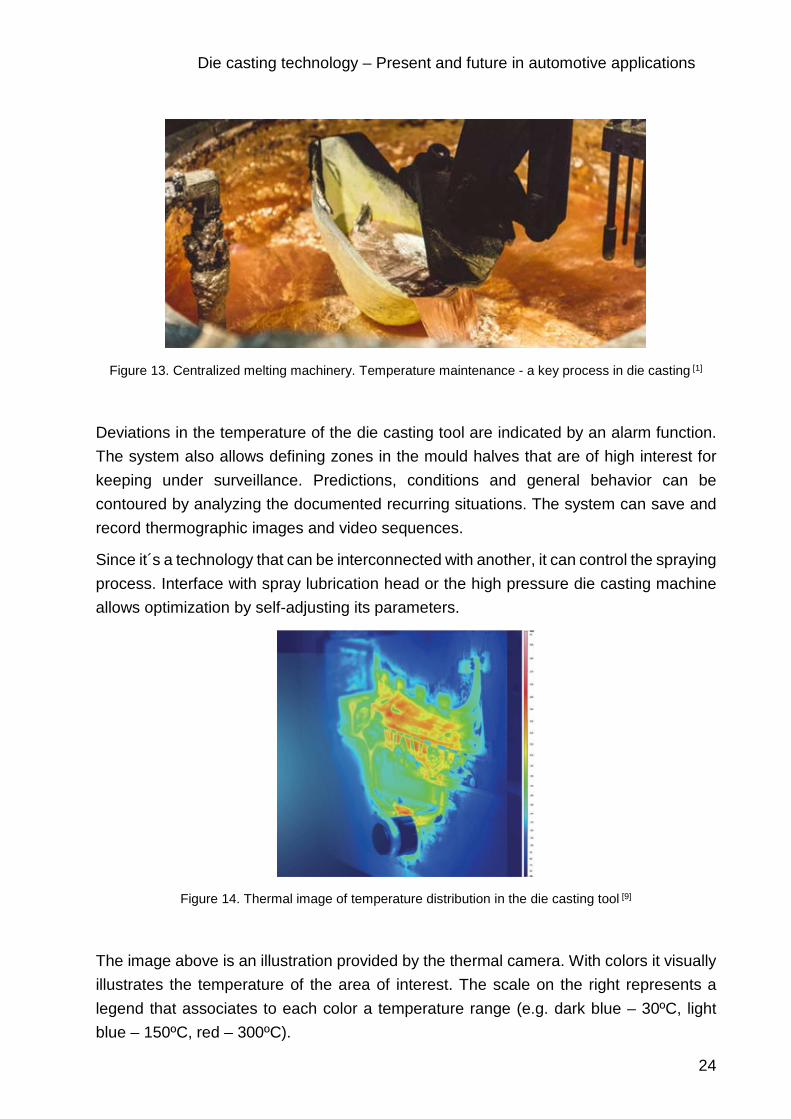
Deviations in the temperature of the die casting tool are indicated by an alarm function. The system also allows defining zones in the mould halves that are of high interest for keeping under surveillance. Predictions, conditions and general behavior can be contoured by analyzing the documented recurring situations. The system can save and record thermographic images and video sequences.
Since it´s a technology that can be interconnected with another, it can control the spraying process. Interface with spray lubrication head or the high pressure die casting machine allows optimization by self-adjusting its parameters.
Figure 14. Thermal image of temperature distribution in the die casting tool [9]
The image above is an illustration provided by the thermal camera. With colors it visually illustrates the temperature of the area of interest. The scale on the right represents a legend that associates to each color a temperature range (e.g. dark blue – 30ºC, light blue – 150ºC, red – 300ºC).

Die casting technology – Present and future in automotive applications
25
Below a graphical representation states as an example of temperature trajectory between the stated ranges and its variations.
Figure 15. Illustration of temperature trajectory with thermal imaging camera [9]
Cycle time reduction, spray optimization, energy efficiency, safety of the operators, quick and reliable leak detection, no porosity, are some of the thermal imaging cameras incorporation, together with improvement of product quality, economic and ecological advantages.
3.2.3 Internationalization in die casting
One of the main objectives of automobile suppliers is to provide reliable parts with a high quality in time. Therefore, an important advantage when automobile manufacturers are sourcing is represented by the geographical distance that their suppliers operate their own manufacturing facilities. In order to reach these expectations, die casting foundries must cope with many challenges. One of them is globalization. The global connections between industries make automotive suppliers deal with a high international competition. Proximity to future markets is the long-term strategic answer to this significant challenge. One of the key drivers of internationalization is the speed of growth of automotive industry. In the present, OEMs are partly situated in growth regions. However, specialist forecast that in the near future, growth will happen outside the existing growth regions. In the long term, only the factories that have the short-term strategic decision to expand in the future markets will be successful. Growth regions such as China, India and Mexico should be considered as potential regions for expansion.
Another option would be to do the expansion through cooperation or joint venture. It´s an easier way for small foundries to internationalize. Integration in this case can take place through clients (forward integration), through suppliers (backward integration) or through competitors (horizontal integration). Tier 1 suppliers are already reaching success by purchasing aluminum foundries and turning into leading competitors.

Die casting technology – Present and future in automotive applications
26
Among competitivity and proximity to markets, another factor that play a huge role in internalization is the cost optimization. Cost optimization can successfully be achieved through expansion or building new plants in new countries. Internalization has the advantage of choosing between different locations in terms of wage, raw material costs and overall supply chain reduced costs. In the short-term, the foundries oriented to provide for the OEMs have to position themselves internationally.
Every foundry is directly influenced by the factors mentioned above. Zatorcal should analyze the prospect of getting closer to strategic suppliers and to future markets to be able to quickly react to new requirements, new trends and reach cost optimization.
3.2.4 Prototype manufacturing in house
In order to be competitive, foundries need to offer quality products in reduced lead times. Due to blocking points or a limited margin of time during tool construction phase of the projects, delays might appear. One solution that could save the foundry time, money and reputation would be a 3D metal printer that is able to produce real-size parts. 3D printing technology has the ability to provide a complete metal solution by printing metal powder bound in a plastic matrix. It enables new features like closed-cell infill for reduced part weight and cost.
3D printing is sometimes referred to as Additive Manufacturing (AM). In 3D printing, one creates a design of an object using software, and the 3D printer creates the object by adding layer upon layer of material until the shape of the object is formed. The object can be made using a number of printing materials, including plastics, powders, filaments and paper.
There are different types of 3D printing technologies available. Below, an overview of these technologies is presented. [10]
Stereolithography (SLA)
Stereolithography makes use of a liquid plastic as the source material and this liquid plastic is transformed into a 3D object layer by layer. Liquid resin is placed in a vat that has a transparent bottom. A UV (ultra violet) laser traces a pattern on the liquid resin from the bottom of the vat to cure and solidify a layer of the resin. The solidified structure is progressively dragged up by a lifting platform while the laser forms a different pattern for each layer to create the desired shape of the 3D object. The schematic representation of stereolithography illustrates how a light-emitting device such as a laser (a) selectively illuminates the transparent bottom (c) of a tank (b) filled with a liquid photo-polymerizing resin. The solidified resin (d) is progressively dragged up by a lifting platform (e).

Die casting technology – Present and future in automotive applications
27
Figure 16. Schematic representation of stereolithography [11]
Digital light processing (DLP)
3D printing DLP technology is very similar to stereolithography but differs in that it uses a different light source and makes use of a liquid crystal display panel. This technology makes use of more conventional light sources and the light is controlled using micro mirrors to control the light incident on the surface of the object being printed. The liquid crystal display panel works as a photomask. This mechanism allows for a large amount of light to be projected onto the surface to be cured, thereby allowing the resin to harden quickly.
Fused deposition modeling (FDM)
With this technology, objects can be built with production-grade thermoplastics. Objects are built by heating a thermoplastic filament to its melting point and extruding the thermoplastic layer by layer (2 - Deposited material). Special techniques can be used to create complex structures. For example, the printer can extrude a second material that will serve as support material for the object being formed during the printing process (1 - Nozzle ejecting molten material). This support material can later be removed or dissolved. All these processes take place on a controlled movable table (3).
Figure 17. Fused deposition modelling [12]

Die casting technology – Present and future in automotive applications
28
Selective laser sintering (SLS) SLS has some similarities with stereolithography. However, SLS makes use of powdered material that is placed in a vat. For each layer, a layer of powdered material is placed on top of the previous layer using a roller and then the powdered material is laser sintered according to a certain pattern for building up the object to be created. The portion of the powdered material that is not sintered can be used to provide the support structure and this material can be removed after the object is formed for re-use.
Figure 18. Selective laser sintering process [13]
Selective laser melting (SLM)
The SLM process is very similar to the SLS process. However, unlike the SLS process where the powdered material is sintered the SLM process involves fully melting the powdered material.
Electronic beam melting (EBM)
This technology is also much like SLM. However, it makes use of an electron beam instead of a high-powered laser. The electron beam fully melts a metal powder to form the desired object. The process is slower and more expensive than for SLM with a greater limitation on the available materials.
Laminated object manufacturing (LOM)
This is a rapid prototyping system. In this process, layers of material coated with adhesive are fused together with heat and pressure and then cut into shape using a laser cutter or knife. More specifically, a foil coated with adhesive is overlaid on the previous layer and a heated roller heats the adhesive for adhesion between the two layers. Layers can be made of paper, plastic or metal laminates. The process can include post-processing steps that include machining and drilling. This is a fast and inexpensive method of 3D printing. With the use of an adhesion process, no chemical process is necessary and relatively large parts can be made.

Die casting technology – Present and future in automotive applications
29
Figure 19. Laminated object manufacturing [14]
Rapid prototyping processes such as the 3D metal printer are particularly suitable for individual prototypes. It is a more economical alternative, and a further advantage is in the cases where the design is not frozen, it still needs to be changed and modifications are considered. Prototype can help close the design, and leave it ready for the tool construction, avoiding reworking subsequently with chamfer milling the die-casting tool.
Being able to go from design to fully functional metal parts in under 24 hours, the metal 3D print system is the ultimate manufacturing solution.
The required material for this technology is up to 10 times less expensive than alternative metal additive manufacturing technologies and up to 100 times less than traditional fabrication technologies like machining or casting. [10]
The technology is called ADAM (atomic diffusion additive manufacturing) and stands at the intersection of 3D printing and metal injection moulding. The printed metal part that can have a complex geometry is fully functional and ready to use having a corrosion resistance of 316L stainless steel. [10]
The principle behind this technology stand in the fact that the metal powder bound in plastic is printed layer by layer into the shape of the designed part. Parts are scaled up after in order to compensate for shrinkage during the sintering process. The resulted parts are then washed to remove the extra binder. They are then sintered in a furnace and the metal powder fuses into solid metal which makes the resulted part similar to a die casted one. The final part is then immediately ready for use, being built of pure metal and is characterized by having a density of up to 99.7%. This makes it suitable for further processing or treatments just like any other metal part.
However, additive manufacturing loses its advantages when used for large quantity production. High costs for the metal powder and the high time required make it a process
Die casting technology – Present and future in automotive applications
30
suitable only for individual prototype production. Another disadvantage is that magnesium components are not able to be produced by this technology because of the fire hazard.
3.2.5 Other possible improvements
Cleanliness specifications are among the first requirements from automotive manufacturers to their suppliers. Combining the washing process with the deburring one through water pressure washing machine could lead to significant cost improvement and customer satisfaction.
From supply chain point of view and for a better traceability, RFID technology could be implemented directly into the product. Once this technology is implemented, process automatization is also possible. Therefore, human errors and extra verification documents can implicitly be eliminated. Machines could easily replace them. Reduction in personnel costs and human mistakes add real value to the business.
The word nanotechnology is widely used as shorthand to refer to both the science and the technology of this emerging field. Narrowly defined, nanoscience concerns a basic understanding of physical, chemical, and biological properties on atomic and near-atomic scales. Nanotechnology, narrowly defined, employs controlled manipulation of these properties to create materials and functional systems with unique capabilities.
Nanotechnology can be used in manipulation and manufacturing of products and devices on a scale of atoms or small groups of atom. The technique of working at the nanoscale have become essential to electronic engineering, and nano-engineered materials have begun to appear in consumer products. Nanotechnology may make it possible to manufacture lighter, stronger, and programmable materials that require less energy to produce than conventional materials, that produce less waste than with conventional manufacturing, and that promise greater fuel efficiency. Materials built at this scale often exhibit distinctive physical and chemical properties due to quantum mechanical effects. Nano-coating for both opaque and translucent surfaces may render them resistant to corrosion, scratches, and radiation. Nanoscale systems with unprecedented levels of information processing may be fabricated. By producing nanotechnology inside the material, it could provide information regarding that material. The traceability once again could reach another level by providing improved performance, reliable information.
Using the processes of nanotechnology, basic industrial production may veer dramatically from the course followed by steel plants and chemical factories of the past. Raw materials will come from the atoms of abundant elements—carbon, hydrogen, and silicon—and these will be manipulated into precise configurations to create nanostructured materials that exhibit exactly the right properties for each particular application. For example, carbon atoms can be bonded together in a number of different

Die casting technology – Present and future in automotive applications
31
geometries to create variously a fibre, a tube, a molecular coating, or a wire, all with the superior strength-to-weight ratio of another carbon material - diamond. Additionally, such material processing need not require smokestacks, power-hungry industrial machinery, or intensive human labor. Instead, it may be accomplished either by “growing” new structures through some combination of chemical catalysts and synthetic enzymes or by building them through new techniques based on patterning and self-assembly of nanoscale materials into useful predetermined designs. Nanotechnology ultimately may allow people to fabricate almost any type of material or product allowable under the laws of physics and chemistry. While such possibilities seem remote, even approaching nature’s virtuosity in energy-efficient fabrication would be revolutionary. [16]
Figure 20. Applications of nanoparticles [17]
3.2.6 Vacuum assisted die casting
Vacuum-assisted die casting reduces gas entrapment during metal injection and decreases porosity in the casting, which leads to a higher level of quality of parts. The

Die casting technology – Present and future in automotive applications
32
vacuum pump is attached at the end of die assembly process. The functionality is illustrated in the picture below.
Figure 21. Vacuum assisted die casting [11]
3.2.7 Die spraying process
Dies could be cooled between shots with die spray. Replacement of lubricants with spraying cooling solution on the faces of the dies for casting separation lead to improve quality of production. The functionality scheme is shown in the picture below.
Figure 22. Cool die casting spraying concept [11]

Die casting technology – Present and future in automotive applications
33
3.3 Materials now
Die casting is notable for its capacity to manufacture parts with a high degree of uniformity, close design accuracy, and quality surface finishes. In many cases, die casting can reduce or eliminate the need for post-production machining, raising the cost-efficiency of the process and shortening fabrication time. While it may be difficult to die cast sturdier metals, such as certain grades of steel, there are many other types of well-suited for die casting methods.
Figure 23. Magnesium car audio heat sink and touch-panel housing [1]
There are several metal materials suitable for die casting manufacturing, such as: aluminum, steel, zinc, copper, brass, cast iron and magnesium.
3.3.1 Steel – the material of the present
The main factors of selecting materials includes a wide variety of characteristics such as thermal, chemical or mechanical resistance, ease of manufacture and durability. Therefore, in case of necessity of a material with these characteristics, steel is the first choice. There were many developments in irons and steels over the past couple decades that made the steel more light-weight, stronger, stiffer and improving other performance characteristics. Applications include not only vehicle bodies, but also engine, chassis, wheels and many other parts. Iron and steel form the critical elements of structure for the vast majority of vehicles, and are low-cost materials. During the past years, steady increases in the use of high-strength steels have been seen, that are referred to as high-strength, low-alloy steels. The prime reason for using steel in the body structure is its inherent capability to absorb impact energy in a crash situation.
Nowadays, steel is one of the most used material for components and structures in automotive industry. New possible business cases are highly related to steel components, since most of the new technologies will have in mind the replacement of

Die casting technology – Present and future in automotive applications
34
steel made parts. When it comes to weight reduction strategies, replacement of steel components makes the top of the list.
3.3.1 Typically used materials in die casting and their main properties and
applications
From the creation of scale replica cars and airplanes to the durable mechanical parts housed in their real-life counterparts, die casting is one of the most cost-effective and versatile manufacturing processes in the world.
Die casting is a precision process that involves injecting molten metal under high pressure into a die, or mould, of a desired shape. Dies are usually constructed with long-lasting, quality steel. Upon solidification and cooling of the material, the design, which can support a range of complex geometries and intricate details, is ejected for quenching, machining or finishing.
This process can be repeated again and again with incredible dimensional accuracy, making it one of the best ways for manufacturing a high volume of castings.
In addition, some castings can be completely finished when they are ejected from the die, which can eliminate the need for machining and additional finishing work. By offering a high-speed production process, precision and high-quality castings, die casting has become a valuable manufacturing method since its invention in 1838. [12]
One of the most important choices to make when setting out to die cast a design is determining the type of alloy best suited to its specific application. Aluminum, magnesium, zinc, and zinc-aluminum (ZA) are the most common types of metallic alloys used in the die casting process.
Each alloy has its own physical and mechanical properties, which are important factors in determining the longevity, strength and overall functionality of the finished product.
The tables below present their mechanical and physical properties and the composition of each alloy. The last column states whether it is suitable to die cast in a hot chamber die casting technology or with a cold chamber die casting technology.

Die casting technology – Present and future in automotive applications
35
Aluminum
Aluminum casting is a widely used method, due in large part to the superior versatility of the metal. It is one of the materials able to undergo most metal casting processes, being a relatively adaptable substance to work with. Aluminum's outstanding corrosion resistance, high thermal/electrical conductivity, good mechanical properties and strength at high operating temperatures make it an effective choice for die casting. It is also a lightweight material, having a good strength-to-weight ratio, good finishing characteristics and is fully recyclable. [20]
Table 2. Mechanical properties of aluminium [21]

Die casting technology – Present and future in automotive applications
36
Table 3. Physical properties of aluminum [21]
Table 4. Composition of aluminum alloys [21]

Die casting technology – Present and future in automotive applications
37
Magnesium
Apart from being the lightest of all the structured materials, Magnesium also has excellent stiffness and strength-to-weight ratios. Additionally, it has outstanding shielding properties, perfect for connectors and electrical housings. Other benefits of magnesium die castings include: high electrical and thermal conductivity, good environmental corrosion resistance, high dimensional accuracy and stability, it has good finishing characteristics, exceptional thin wall capability and can withstand high operating temperatures. It is also known for its full recyclability.
Table 5. Mechanical properties of magnesium [21]
Table 6. Physical properties of magnesium [21]
Table 7. Composition of magnesium alloys [21]
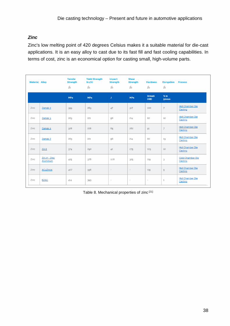
Die casting technology – Present and future in automotive applications
38
Zinc
Zinc's low melting point of 420 degrees Celsius makes it a suitable material for die-cast applications. It is an easy alloy to cast due to its fast fill and fast cooling capabilities. In terms of cost, zinc is an economical option for casting small, high-volume parts.
Table 8. Mechanical properties of zinc [21]

Die casting technology – Present and future in automotive applications
39
Table 9. Physical properties of zinc [21]
Table 10. Composition of zinc alloys [21]
3.3.2 Different alloys properties and the die casting process
Each alloy has its own physical and mechanical properties, which are important factors in determining the longevity, strength, and overall functionality of the finished product. Unlike copper or ferrous alloys, the most commonly used alloys have lower melting temperatures, which influences cast ability. The complexity of the part, the minimum wall thickness and the required precision of the part will also influence how castable it is.

Die casting technology – Present and future in automotive applications
40
Depending on the application of design and the metal alloy used, there are several different methods of die casting which offer more flexibility in manufacturing. These include the hot chamber and cold chamber processes.
Hot chamber die casting is ideal for metals with lower melting temperatures like zinc and magnesium, and cold chamber processes are used for metallic alloys like aluminum that have higher melting temperatures. Squeeze casting is a process that requires no gas entrapment and produces high-quality components.
Aluminum, magnesium, zinc and zinc-aluminum are the four most commonly used alloys in die casting processes. The design’s application, material density, tensile strength, yield strength, melting temperature and modulus of elasticity are all important factors in selecting the alloy best suited for the design needs.
While it is not considered as castable as zinc due to a higher melting temperature, aluminum is the most commonly used alloy in the die casting industry, and it remains one of the most economical materials used in high-volume casting projects. Die cast aluminum parts can be found in a broad range of components used to run a car to the electronics and power tools millions of people utilize every day.
With a specific gravity of 2.7, aluminum is considered to be a lightweight, structural material, but it is rarely cast in its purest form.
Because of the risk of hot cracking and shrinkage, aluminum is often alloyed with other materials including silicon, magnesium and copper. Silicon increases fluidity, pressure tightness and modulus of elasticity in the alloy. In addition, silicon also reduces the metal’s specific gravity, thermal expansion and shrinkage. It also improves corrosion resistance.
Copper is used to increase corrosion resistance, tensile strength and the hardness of the alloy, providing it with superior mechanical properties.
There are now several aluminum alloys available to designers which are practical for a wide range of applications because of their varying physical and mechanical properties.
In addition to being lightweight, aluminum alloys are also resistant to corrosion, maintain strength at high temperatures provide high dimensional stability when casting intricate geometries and areas with thin wall thickness. They also possess high thermal and electrical conductivity. Machining aluminum is easier as well when compared to other materials including iron, steel and titanium.
Automotive components suitable for casting made of the above mentioned materials could be: brake system (brake calipers, master cylinder), fuel supply system (fuel rails, petrol collectors, diesel engine pump), engine and suspension (engine block, suspension

Die casting technology – Present and future in automotive applications
41
arms, belt cover, pulleys, pistons), steering system (power-steering valve box, clutch, cylinder, wheels).
3.3.3 Aluminum alloys and their benefits
A wide range of aluminium alloys are utilised in manufacturing.
Classification of aluminum alloys is established by the International Alloy Designation System (IADS), based on the classification developed by Aluminum Association of the United States. This classification is accepted by most countries. [22]
Each cast aluminum alloy is designated by a four digit number with a decimal point separating the third and the forth digits.
The first digit indicates the alloy group according to the major alloying element:
o 1xx.x Aluminum 99.0% minimum o 2xx.x Copper (4%...4.6%) o 3xx.x Silicon (5%...17%) with added copper and/or magnesium o 4xx.x Silicon (5%...12%) o 5xx.x Magnesium (4%...10%) o 7xx.x Zinc (6.2%...7.5%) o 8xx.x Tin o 9xx.x Others
The second two digits identify aluminum alloy or indicate the alloy purity.
In the alloys of the 1xx.x series the second two digits indicate the level of purity of the alloy – they are the same as the two digits to the right of the decimal point in the minimum concentration of aluminum (in percentages): 150.0 means minimum 99.50% of aluminum in the alloy, 120.1 means minimum 99.20% of aluminum in the alloy.
In all other groups of aluminum alloys (2xx.x through 9xx.x) the second two digits signify different alloys in the group.
The last digit indicates the product form: casting (designated by “0”) or ingot (designated by “1” or “2” depending on chemical composition limits.)
A modification of the original alloy or impurity limits is indicated by a serial letter before the numerical designation. The serial letters are assigned in alphabetical order starting with A but omitting I, O, Q, and X (the letter “X” is reserved for experimental alloys).
The finished metal typically belongs to the 1xxx, 3xxx, 5xxx or 8xxx alloy series. All alloys in the same series share similar properties. [22]

Die casting technology – Present and future in automotive applications
42
1xxx series: Provide corrosion resistance, good formability, weldability and conductivity.
3xxx series: Exhibit moderate resistance to atmospheric and chemical agents, and offer higher mechanical properties and better formability than pure aluminum.
5xxx series: Typically used in applications in which corrosion resistance, high strength, good response to surface treatment, and good surface finish are required. 5xxx series alloys respond well to gloss variations achieved by etching or brightening, and the final aesthetic finish obtained after anodizing. They also offer excellent formability and good weldability.
8xxx series: Offer a combination of properties similar to 1xxx series alloys but with higher strength, better formability, and improved stiffness. 8xxx series alloys are normally suitable for thinner gauge applications.
Alloy 380 is used in a variety of products including home appliances, furniture, power tools, automotive parts, electronics and lawnmower housings because it offers the best range of properties for both the finished product and casting. With a combination of 8.5 percent silicon, and 3.5 percent copper. [22]
Alternatives to alloy 380 include alloys 383 and 384, which are more resistant to hot cracking, and they offer improved die filling characteristics during the casting of complex components.
When compared to other aluminum alloys, alloy 360 offers greater strength during exposure to higher temperatures. It also offers better resistance to corrosion.
Alloy 443 offers the highest ductility, or the ability to stretch under tensile strength, of all aluminum alloys.
While zinc is ideal for casting components with thin walls, aluminum alloy 413 is useful for casting a variety of intricate parts. When manufacturing hydraulic cylinders, or other pressure machinery, it also offers better pressure tightness compared to its counterparts.
Alloy 390 provides better resistance to abrasion and wear, and it was originally developed for automotive engine blocks. However, alloy 390 offers the lowest ductility of aluminum alloys with elongation less than 1 percent.
Higher ductility comes from Alloy 518, which also possesses excellent resistance to corrosion when compared to other alloys used in casting.
3.3.4 Magnesium alloys
Magnesium is another lightweight structural material commonly used in die casting, but like aluminum, it is alloyed with other metals to provide greater stability and better mechanical properties. In combination with metals like silicon, manganese, aluminum and
Die casting technology – Present and future in automotive applications
43
zinc, magnesium alloys have become a great asset to the die casting industry. With a specific gravity of 1.7, magnesium is the lightest of the commonly used alloys available.
Cast magnesium alloys are manufactured by die casting, permanent mold casting and sand casting methods.
Cast Magnesium-Aluminum-Manganese Alloys (AM100A, AM60A) are heat-treatable and may be strengthened by precipitation hardening (solution treatment followed by aging). Alloys AM60B, AM50A and AM20 are also commonly used in die casting, but they offer better ductility, while still maintaining corrosion resistance and strength. For applications that require enhanced strength when exposed to higher temperatures, alloys AS41B and AE42 are often the best option.
Cast Magnesium-Aluminum-Zinc Alloys (AZ63A, AZ81B, AZ91A, AZ92A) may be hardened by heat-treatment. The alloys have good mechanical strength combined with excellent ductility and impact toughness. Alloy AZ91D is about 9 percent aluminum and 1 percent zinc, and it is the most widely used available magnesium alloy. AZ91D offers excellent strength, corrosion resistance and better cast ability compared to other magnesium alloys. By putting limits on impurities such as iron, copper and nickel, better corrosion resistance is obtained, making AZ91D one of the best choices when casting components that need to withstand wear.
Cast magnesium-aluminum-zinc alloys are used for manufacturing automotive wheels and structures, components of electric instruments and motors, plastic molds.
Cast Magnesium-Rare Earth-Zirconium- Alloys (EZ33A, EK30A, EK41A) may be hardened by heat treatment.
Cast magnesium-rare earth-zirconium alloys have good mechanical strength at elevated temperatures – up to 500°F (260°C).
Cast Magnesium-Zinc-Zirconium Alloys (ZK51A) may be hardened by heat treatment.
The alloys possess high yield strength combined with good ductility.
Cast magnesium-zinc-zirconium alloys are used for manufacturing small and relatively simple highly stressed parts.
Cast Magnesium-Thorium-Zirconium Alloys (HK31A, HZ32A, ZH42, ZH62A) may be hardened by heat treatment.
The alloys have good mechanical strength at the temperatures above 500°F (260°C) and good Creep resistance.
Magnesium is lightweight, and it has a durable structure for certain die cast components. Substituting magnesium components in place of heavier aluminum ones may contribute

Die casting technology – Present and future in automotive applications
44
to lower fuel costs in vehicles, which has car manufacturers developing new technology to utilize magnesium’s unique properties.
For engine components that are susceptible to higher temperatures and corrosion, alloys AS41B and AE42 are an excellent choice. All magnesium alloys exhibit a high tensile yield strength and modulus of elasticity. [24]
3.3.5 Aluminum vs. magnesium alloys
Like aluminum, magnesium alloys are utilized in the casting of automotive parts and provide their own unique mechanical and physical properties. While there have been experiments conducted to substitute magnesium for aluminum, it is still softer, less stable, more expensive and tends to bend easier when under stress.
While aluminum alloys take longer to solidify compared to magnesium alloys, its alloys provide a longer die life. In addition, aluminum does not require as much finishing work as magnesium. Special treatments and coatings are needed when determining a magnesium casting’s application.
When compared to the cost of melting aluminum, new technology has lowered the expenses required to melt magnesium alloys, but casting requires a higher injection speed. Conversely, magnesium has a quicker ejection time over aluminum casting. Magnesium is also better at casting components with thinner walls and tighter tolerances than aluminum.
However, even with the many advantages of magnesium, aluminum remains a less expensive alternative for die casting.
3.3.6 Zinc vs. magnesium alloys
One of the main differences between magnesium and zinc alloys is that zinc and zinc-aluminum alloys require lower pressure and temperatures for casting. Because of a lower casting temperature, zinc provides a much longer die life than magnesium, which can help reduce production costs.
Unlike magnesium, which requires special treatments and coatings for corrosion resistance and finishing, zinc alloys also offer excellent corrosion resistance and a better surface finish when they are ejected from the die.

Die casting technology – Present and future in automotive applications
45
3.3.7 Zinc and zinc-aluminum alloys
When it comes to casting components with tight tolerances and areas with thinner wall sections, no other alloys compare to the zinc and zinc-aluminum alloys. The element has a specific gravity of 7.0, making it one of the heaviest materials commonly used in die casting. Zinc is perfect for miniature die casting parts in high volume through a special hot-chamber injection process.
Like magnesium and aluminum, zinc is alloyed with other metals to provide better corrosion resistance, stability, dimensional strength and impact strength. Several of the available zinc alloys are referred to as zamak, an acronym for zinc, aluminum, magnesium and copper.
Zinc 3 is the most commonly used zinc alloy, and it is sometimes exclusively used by die casters because of its tendency to be priced lower. In addition, the alloy provides a better surface finish during higher production rates, and it’s still capable of casting stable, intricate designs and complex components.
Another alternative to Zinc 3 is Zinc 5, which is used for its increased tensile strength, hardness and lower ductility. When it comes to producing a higher volume of components with thin walls, Zinc 7 can be used as it has a higher fluidity than other zinc alloys, which could increase production rates.
When looking for the highest strength and creep resistance, or deformation under mechanical stress, the Zinc-Aluminum alloy, ZA-8, is the best choice. With 8.4 percent aluminum and 1 percent copper content, ZA-8 provides lower densities with higher resistance to wear. Zinc alloys also provide better impact strength when compared to other commonly cast alloys. [25]
3.3.8 Aluminum vs. zinc alloys
Just like with magnesium, one of the main differences between aluminum and zinc alloys is that zinc has a lower melting temperature and requires lower pressures for casting. Zinc is considered to be the most castable of all of the commonly used alloys.
By having a lower melting temperature, this enables a zinc die to last much longer than an aluminum die. Dies are expensive, and keeping them in service longer will provide a more cost-effective approach to large volume casting projects.
In addition, zinc’s lower melting temperature allows for hot chamber casting, which is less expensive than cold chamber processes. By using the hot chamber die casting method, production speed will also be increased. Zinc is one of the toughest alloys around, and it surpasses even aluminum in its ability withstand impact.

Die casting technology – Present and future in automotive applications
46
Another advantage to using a zinc alloy over an aluminum one is that zinc is great for castings with very intricate details and thin walls. When utilizing zinc, very little machining, trimming or finishing work is needed as the lower pressure and melting point reduce the thermal shock it experiences during casting. When casting in zinc, it maintains a smoother surface when a component is ejected from a die.
3.3.9 Determining alloy and casting costs
Aluminum remains the most inexpensive alloy per cubic inch of all the commonly used alloys in die casting, but market value still fluctuates. Depending on the application and size of your design, costs may be lower based on the amount of material needed and the weight of the material.
Magnesium and aluminum are lightweight materials that offer excellent stability, but they have higher melting temperatures than zinc, which can contribute to higher casting costs. Hot chamber casting, which can be utilized with zinc and magnesium alloys, is less expensive than cold chamber processes, and it can run at a faster rate.
Die manufacturing is also an expensive process, and while the costs remain steady for the actual production of the die, determining the overall expected life a die is a good way to reduce expenses. For alloys like zinc, die life lasts much longer. Magnesium’s melting temperature is lower than aluminum and will allow for a longer die life as well.
When considering what alloy best suits your design needs, machining and finishing operations should also be considered. Zinc and zinc-aluminum alloys offer superior results over aluminum and magnesium when it comes to finishing, and they can drastically reduce the workload needed to produce a final product.
The most important thing to consider when selecting an alloy is the unique mechanical and physical properties they provide and how those will impact the performance and longevity of your design’s application.
For projects involving exposure to higher temperatures, aluminum offers better strength than other alloys. For designs that require a high yield strength and modulus of elasticity, zinc alloys are the best choice. Magnesium also offers many benefits due to its lighter weight, and it can be substituted for aluminum for specific components.

Die casting technology – Present and future in automotive applications
47
4 Vehicles of the future
Automotive industry is a sector that has been in a continuous change. Lately, because of fuel shortages and preoccupation for the environment, it has become necessary for people to use better and more efficient forms of energy that is not limited to regions like the case of fossil fuels in order to drive their cars. This is how the modern electric car has been invented. It is known for its efficiency and its reduced energy consumption, a feature that makes it environmentally friendly.
Figure 24. Autonomous car – Renault EZ-GO, as seen in Automobile Barcelona Motor Show, 2019

Die casting technology – Present and future in automotive applications
48
4.1 Electromobility
Most of the cars nowadays that humanity used for almost a century are powered by internal combustion engines. Most of these engines run on diesel or gasoline fuel. These engines release vast amount of energy when ignited which is then used to power the vehicle.
In the present time, there are the new breed of cars commonly known as the electric cars that are run by an electric engine and there are those that have hybrid propulsion system. However, the cleanest of them all are those with electric engines and they are the ones currently a hot sale in the market today.
Electric cars are powered by rechargeable batteries installed inside the car. In appearance, electric cars look like conventional vehicles, lacking only the exhaust system. On the inside, however, they are designed differently. Since electric cars do not use fuel for locomotion or for propelling the engines, they do not have a gas tank.
As a consequence, the battery packs are placed in the vehicle lower area or sometimes in the trunk. As battery systems, lithium-ion technology is used.
Climate controls system, brakes as well as air bags are the same as in traditional cars. One of the main differences is the electric motor. There are two types of them in the market: AC induction motor and permanent magnet synchronous motor.
The 3 principal components of an electric car are: electric motor, controller and battery. When you switch on the car, the current is passed from the battery. The controller takes power from the battery and passes it on to the electric motor. Before passing the current to motor, the controller converts the DC into AC, 3 phase power, to drive the motor. The electric motor then converts electrical energy to mechanical energy. The mechanical energy moves the vehicle forward. Controller stands as the buyer of power from battery and gives output power to motor accordingly. Variable potentiometers are connected between accelerator and the controller. These potentiometers tell the controller how much power it is supposed to deliver.
Below, there are listed the types of used batteries.
Lithium ion batteries are known for giving extra performance. They are lighter than Lead acid and Nickel metal. These are the batteries are also used to store data in digital camera or smart phone.
Lead acid battery: These batteries are the most popular, cheapest and 97% recyclable, but not applied in electric cars for supply of the propulsion system.

Die casting technology – Present and future in automotive applications
49
Nickel metal hydride batteries: They are cost much more than lead acid but provide higher output and better performance, but less than lithium-ion batteries.
Battery housings for electric vehicles represent a subject of interest for die casting foundries since it represents a new business case that enriches their product portfolio. It is suitable for die casting technology because of its robustness requirement to be crash resistant, lightweight design and made of steel/aluminum.
Apart from the integrated crash safety design and underbody protection, it has a flat design, which makes die casting the perfect manufacturing method. Among the other characteristics of the housing, I will emphasize the need to include a cooling system, corrosion protection and impermeability, it has to be electromagnetic compatible with the battery and most of all to be easy to assemble and change in case of damaging or internal short circuit.
Figure 25. Battery housing in an electric car [13]
As the electric car moves, the forward momentum generated by electric motor can be used to charge the batteries when the brakes are applied. This is a phenomenon commonly referred to as regenerative braking and can recover up to about 85% of used energy for acceleration. This is done by applying generated momentum in braking process to the car batteries. As much as this is effective, it does not however generate enough to fully recharge the car fully to run it. Therefore, it is important to charge battery additionally, e.g. at the electric grid.
4.1.1 Electromobility: definition, vehicles and future
Electromobility is defined as the use of electric vehicles. Originally this is referred to all types of vehicles (from bicycles to high-speed trains).

Die casting technology – Present and future in automotive applications
50
Electromobility is one of the main topics in the automotive industry. Car manufacturers are working on major product developments.
In the early days of automotive history, around 1900, there were more electric cars in the USA than with combustion engines. Only inventions such as the starter motor made the combustion engine ready for series production. In the decades that followed, the electric motor was only playing a niche role. In the 1970s, for example, milk floats were in great demand in Great Britain: Small vans that delivered the milk silently in the morning.
Figure 26. "Semper Vivus" with electric wheel hub drive developed by Ferdinand Porsche [14]
Late electrification started in 1997 with the Toyota Prius, which is a hybrid-electric car. It has produced so far, a total of almost eleven million units. [15]
4.1.2 Types of electric drives
Hybrid (HEV) — It is a combination of combustion engine and electric motor
Mild Hybrid — Hybrid with electric motor of limited power, which supports the internal combustion engine.
Plug-in Hybrid (PHEV) — Hybrid vehicle with charging ability via the power grid
Electric car with Range Extender (REX) - Additional combustion engine in an electric car that does not drive the vehicle but charges the battery via a generator
Battery (BEV) — A battery electric vehicle without internal combustion engine. Power supply via battery, charging via charging station
Fuel cell — An electric vehicle with fuel cell. By using electrolysis of hydrogen and oxygen, this technology provides electrical energy for the drive and the battery

Die casting technology – Present and future in automotive applications
51
4.1.3 Differences between electric engine and gasoline engine
Energy storage
Electric vehicles store energy inside the battery while gasoline engine driven vehicles use energy produced by ignition of fuel (petrol or diesel).
Environment impact
Electric engines may use energy from renewable energy source like solar, wind or may use energy from non-renewable energy source like coal and natural gas. Gasoline engines on the other hand burn fuel, which releases carbon dioxide and has huge environmental impact.
Fuel
Gasoline engines or other internal combustion engines run by burning of fuel whereas electric engines receive power from rechargeable battery.
Cost
Just as with gasoline cars, some electric vehicles are more efficient than others, and the average EV needs about 30 kWh of electricity to power the vehicle for 100 miles (161 km). For example, the EPA rating for the Nissan LEAF is exactly 30 kWh per 100 miles. A Tesla Model S 60D is rated at a combined 32 kWh per 100 miles and uses a little more energy since it’s heavier and more powerful than a LEAF. The Chevrolet Bolt is currently the most efficient electric car and has a combined consumption rating of 28 kWh per 100 miles. [16]
According to Researchers at the University of Michigan Transportation Research Institute, the sales-weighted average fuel economy of all new vehicles sold in the United States in 2016 was 25.3 mpg (11.6 liters/100km). The average cost for a gallon (3.785 liters) of regular gasoline in the US over the past two years was $2.35/gallon. Using 15,000 miles (24140 km) as the average amount of miles a person will drive in a year, the annual cost of gasoline for the average car will be about $1,400 per year, using the average cost of gasoline in the US from 2015 through 2016. One thing to also consider is that the cost of gasoline is currently much lower than it has been through most the past decade and it’s likely to rise again sometime soon. [17]
Recharge or refuel
A normal gasoline powered car takes less than 5 minutes to fill the empty tank whereas an electric car takes from 30 minutes to 6 hours or even longer to charge. This again depends on the size of battery and the technology.

Die casting technology – Present and future in automotive applications
52
Speed
The speed if an electric vehicle can go up to 130-150 km/hour [18] while the same for a gasoline engine can go up to approximately 200-230 km/hour.
Other aspects include battery types, which makes it more efficient in energy. With the new developments being made today, these electric cars are nearing that stage where they will be seen as the best alternatives to other types of cars. This will greatly reduce pollution associated with combustion in the world today.
4.1.4 Advantages and disadvantages of electric mobility
One of the advantages is locally emission-free driving, although this fact already implies a disadvantage. The extent to which emissions are actually reduced in the overall balance depends on the energy mix. However, the energy required for vehicle production must also be considered. According to a study conducted by the Swedish Energy Agency [19], the life cycle assessment of an electric vehicle is more favorable after 30,000 km (small vehicle) to 100,000 km (large vehicle) than that of a "combustion engine" of the same size. An ecologically critical factor is also the demand for mineral resources (for example Lithium) for battery production.
If the electric cars were powered by regenerative electricity, the balance would be excellent. As an example, the generation of one kilowatt hour of electricity in the electricity mix produces an average of 530 grams of CO2. [33] What needs to be taken into consideration is the fact that the energy mix is different in different from one country to the other.
A clear disadvantage is (still) their limited driving range and the incomplete charging infrastructure, especially of fast charging stations on long-distance routes. The pleasant driving experience (low-noise, high torque right from the start) is regarded as an advantage.
From the point of view of vehicle development, it is positive that the lack of a combustion engine and mechanical drive train allows completely new freedom in construction and design. For the economy and the labor market, electromobility could result in job losses in the automotive industry (including suppliers) because an electric drive is much less complex and requires fewer components than a combustion engine. For example, Volkswagen reported that 7,000 jobs in the Hanover and Emden plants had become obsolete as a result of their electric offensive. [19]

Die casting technology – Present and future in automotive applications
53
4.1.5 Electromobility - current market data
In Germany, between 100,000 and 120,000 electric cars are currently registered (as of December 2018). This corresponds to a share of around 1.9 % (based on new registrations). The goal set by the federal government — one million electric vehicles in Germany by 2020 - will therefore not be realized. But the share of e-cars is now growing and there is a strongly growing supply of new vehicles. In 2018, the German Federal Motor Transport Authority (KBA) registered 36,062 pure electric cars, representing a significantly higher number of new registrations than a year ago (25,056).
In the USA, the benchmark of one million electric vehicles was reached in December 2018. There, the share of new registrations is 1.8 % (based on the first three quarters of 2018). Around 1.2 million electric cars are currently on the roads in China (3.5 % of new registrations), and more than three million worldwide. The highest proportion of new registrations of electric vehicles is in Norway (46.7 %), followed by the Netherlands with 4.7 %. [19]
Figure 27. The Renault Zoe, the best-selling electric car in Germany [20]
The best-selling electric vehicle in the German market in the period from January to July 2018 was the Renault Zoe, with 3,011 units, followed by VW Golf-E, Smart Fortwo EQ, Kia Soul and BMW 3i.
By the year 2030, it is to be expected that sales of passenger cars with combustion engines will decline sharply. In 2035, for the first time worldwide, more cars with electric drives than with combustion engines are likely to be sold. However, since total car sales

Die casting technology – Present and future in automotive applications
54
will rise sharply by then (by 57 % to more than 116 million vehicles in 2030), a considerable number of cars with combustion engines will probably still be produced. [19]
Political framework conditions are also a driver of e-mobility: This is another reason why car manufacturers have an interest in selling electric vehicles in order to keep fleet consumption low and to avoid fines (from 2021) that become due if specified values are exceeded. In addition, driving bans for vehicles with diesel engines are already being considered in numerous metropolises - for example in London, Mexico City and Paris. In the present great cities such as Madrid and Barcelona restricted the access into the city center of vehicles with diesel engines.
Electric drives (including hybrid technology) in these cities can make it possible to travel the "last few miles" to their destination in the city. In addition, electrically operated miniature vehicles like electric pedal scooter, hover boards or other micro vehicles are an alternative, since the legislation now also creates the framework conditions for this future in Europe.
4.1.6 E-cars - energy storage technology
The traction motors used in electric vehicles are mainly three-phase motors. The gearboxes are much simpler and usually two-stage. Lithium-ion rechargeable batteries have established themselves as the state of the art in energy storage.
For decades there was hardly any serious battery research (electrochemistry), at least in Europe. They're catching up now. At the University of Münster, in the MEET Institute around 140 researchers are working on battery technologies of the future - with a focus on automotive applications. The main objectives of battery development are to reduce costs and increase range.
In addition to the enhancement of lithium-ion technology, battery researchers worldwide are also working on making new types of battery systems ready for series production. These include lithium iron phosphate (LiFePO4) technology and - to an even greater extent - solid state batteries, in which both electrodes and the electrolyte are made of solid materials. This enables a higher energy density. Several car manufacturers have announced that they will use solid state batteries in their electric cars from around 2025 onwards. Volkswagen invests € 90 million, for example into a start-up company researching solid state batteries.
Some car manufacturers have set up their own battery system production facilities in which cells are assembled into ready-to-install complete batteries. The battery cells as

Die casting technology – Present and future in automotive applications
55
the heart of the energy storage system are supplied by a few, such as Bosch, to name one. [19]
European car manufacturers need their own cell production – this is currently the subject of intense debate in industry and politics. The reason for this is that batteries account for a considerable part of the added value of an electric vehicle. The question of security of supply also plays a role in this discussion. There are also discussions as to which battery technology will be favored. Much speaks in favor of solid-state batteries. [19]
4.1.7 Charging systems for electric cars
Three or four connector systems are currently the standard on the market. In Europe, the "Type 2" plug and the CCS plug (Combined Charging System) with fast charging function dominate. The CHAdeMO (charge de move) connector is used in Japan. Tesla relies on its own connector system for its "superchargers".
Figure 28. Several connector systems are currently in use [21]
Charging columns - from the wallbox for the garage to the high-power charging system - are offered by various manufacturers. Charging systems with an output of up to 320 or 350 kW (ADS-Tec and ABB) are currently technically feasible. They allow the "refueling" of energy for 200 kilometers within eight minutes.

Die casting technology – Present and future in automotive applications
56
Some electric vehicles, such as the BMW 530e with plug-in hybrid, offer the option of wireless inductive charging. In this case, however, the charging performance is limited. In the future, inductive charging systems are also conceivable (and are already being tested), which are integrated into the roadway and charge the batteries of electric cars while driving. [19]
The acceptance of electromobility depends on the range of a battery charge and - especially for long-distance journeys - on the availability of charging stations and the speed of the charging process.
By 2020, around 15,000 charging stations should be available in Germany, around 5,000 of them with a charging capacity of more than 50 kilowatts. These rapid charging systems ("High Power Charging") are to be installed primarily along the highways. Ionity - a joint venture of Audi, BMW, Daimler, Ford, Porsche and VW - is working on such a network, for example. However, the general power grid is not designed for such charging capacities and grid-supported stationary battery storage will be required. [19]
In practice, there are still obstacles to overcome.
4.1.8 Reaction of automotive manufacturers towards e-mobility
VW alone wants to present around 80 new electric models by 2025 and introduce its own brand ID for electric vehicles in 2020. In November 2018, the Group announced that by 2025 it would invest around 30 billion euros in electric mobility.
Audi has presented the all-electric SUV E-Tron, Mercedes the EQC and Porsche prepares the launch of the Taycan (based on the Mission E study) for 2019. BMW has been on the market with the i3 and i8 models since 2013. Opel has had various Ampera models in its range since 2012 - when it was still a General Motors subsidiary - and Ford plans to introduce several electric car models such as the crossover vehicle Mach E in 2020.
4.1.9 The future of die casting influenced by electromobility
According to experts, it has not been determined whether electromobility is the ideal solution for the era after the use of fossil fuels. There are voices that see electric vehicles only as a bridge technology for other types of energy and drives. In particular, fuel cell vehicles powered by hydrogen could prevail in the medium term, as could alternative liquid fuels (so-called e-fuels).

Die casting technology – Present and future in automotive applications
57
During the past decade, there has been a significant increase in the required volumes of die-casting components. Vehicle manufacture is acquiring more and more of a dominant position in the die-casting market, accounting for 80% now. The remaining 20% of die-casing production is divided between all sorts of different industries.
Discussions about the future of the internal combustion engine represents a source of potential evaluation in die-casting industry changes. It is believed that fewer diesel-powered vehicles are being purchased, therefore manufactured. Introduction of electric vehicles is a factor that highly influences the trajectory of die-casting technology. Due to future-related discussions about internal combustion, die-casting foundries are in need of strategically plan their facilities and get ready for radical changes in demand. There are still a lot of unanswered questions that arose in the context.
Meanwhile, strategic decisions will be taken. They will have a long-term impact on OEMs, policy-makers, die-casting foundries and their suppliers and consumers.
The shift to electromobility is not yet at a mature level. Though, the initial development phase and its positive results can be seen. Along with the market penetration of electric cars will also increase the proportion of lighter parts on the market. This can be done by replacing heavy, steel-made components with light, die-casted parts. The benefits of die-casting can be applied everywhere, from optimized components for controlling traditional engines to structural parts and components for electric drive units. Many new components need die-casting technology to be fabricated. Once electromobility is completely implemented, it will create substantial demands on new foundry business cases. The growing number of die-cast parts used in car bodywork will also increase the demand for structural parts.
New designs and new components in electromobility expand the range of products to be sourced from casting foundries. The challenge stands in the fact that entirely new production lines often have to be created for them. Large electric motors casings can also be made through die-casting method of production, but because of dimensional reasons create new challenges of their own.
To conclude with, there will be an increased need for die-cast parts, even after the change in drive technology.

Die casting technology – Present and future in automotive applications
58
4.2 Autonomous cars
Autonomous car is a vehicle that can drive itself from one point to another without assistance from a driver; in other words, with an autopilot system.
The core mission of present and future cars is safety. Therefore, car manufacturers pushed safety development forward with significant innovations. Driver error is the most common cause of traffic accidents. The use of cell phones and entertainment systems, more traffic and more complicated road systems making it more frequent.
The automotive future is electric. Tendencies and studies show that combustion engines will soon become obsolete. Cars are going to be not only electric, but also autonomous. Experiments have been conducted on automating cars since the 1920s. Ever since, various companies have developed working prototype of autonomous car.
4.2.1 ADAS - The pre-step technology to autonomous driving
ADAS – Advanced driver assistance functions are known as driving assisting functions. Their aim is reduce road accidents and the associated casualties by helping drivers avoid collisions altogether. These systems are designed to react faster than humans, are constantly vigilant, and are already being adopted and deployed across various car segments, from premium to economy models.
ADAS systems constantly monitor the vehicle surroundings, alert the driver of hazardous road conditions, and take corrective actions, such as slowing or stopping the vehicle. These systems use inputs from multiple sensors, such as cameras and radars. The fusion of these inputs is processed and the information is delivered to the driver and other parts of the system. The same sensor technologies can be used both in the current ADAS systems and in the upcoming fully autonomous driving systems (level 4 and 5). [36]

Die casting technology – Present and future in automotive applications
59
Figure 29. Volkswagen – ID BUZZ as seen in Automobile Barcelona Motor Show, 2019
Camera-based technologies provide high-reliability and adaptability for a wide-range of driver assistance applications, for example lane keeping, pedestrian detection, traffic sign recognition, rear view camera, driver monitoring, electronic mirror. Radar-based ADAS uses two different carrier frequencies, 24 GHz for narrow band and 77 GHz for wide band applications, to support features such as blind-spot detection, automatic emergency braking and adaptive cruise control.
4.2.2 The technology behind autonomous cars
Autonomous car concept incorporates easy to use technology with intuitive interfaces, cruise control with stop function through which the vehicle is able to adapt to the speed in front and to maintain the safe distance. In case of necessity, the car is able to stop by itself automatically through the automatic emergency braking. Another feature is the collision risk alert that warns the pedestrians and the passengers in case of a possible accident. The lane departure warning system makes the car automatically go back into the lane in case of deviation. The park assist function detects parking space according to its size and is capable of commanding the steering system in order to successfully complete the parking.
With the introduction of ADAS functions, technology is getting closer to the autonomous driving concept.

Die casting technology – Present and future in automotive applications
60
Night vision onboard system that can identify obstacles and driver attention monitoring system that can track the driver´s alertness are based on high performance sensors. Cars manufacturers are going to incorporate more and more similar advances and improvements in the design of the future cars for a better driving experience and an increased level of safety.
Figure 30. Components that make an autonomous car [22]
Self-driving vehicles are cars or trucks in which human drivers are never required to take control to safely operate the vehicle. Also known as autonomous or "driverless" cars, they combine sensors and software to control, navigate, and drive the vehicle. The components that make the autonomous vehicle are represented by systems like: lidar (light detection and ranging), radar system, ultrasonic sensors, video cameras, GPS (global positioning system), inertial measurement unit, CPU or computer.
Once the driver sets a destination, the car’s software calculates a route and starts the car on its way. A rotating, roof-mounted lidar sensor monitors a 60-meter range around the car and creates a dynamic 3-D map of the car’s current environment. A sensor on the left rear wheel monitors sideways movement to detect the car’s position relative to the 3-D map.

Die casting technology – Present and future in automotive applications
61
Lidar system
It is a remote, laser-based scanning technology that images objects in 3D. It uses laser, ultra violet, visible light or infrared light to image objects. By illuminating a target with a light beam and analyzing the reflected light, it is able to measure distances.
Self-driving cars may be able to ‘see’ the world in 3D. Self-driving cars must be able to visualize the world around them and differentiate between objects such as roads, buildings and people in order to be able to operate safely on our urban roads.
Essentially the cars vision system needs to be able to mimic what a human driver does as they constantly scan the road and immediate environment around them with their eyes making a thousand micro decision about speed, direction etc.
Self-driving cars need to have enough information so that they can plan ahead to avoid upcoming incidents such as a potential crash.
Many self-driving car companies use a lidar (Light Detection and Ranging) system to do this. One of them is General Motors. The technology uses spinning lasers to build up a 3D map of the environment. [38]
The system should also be placed on the roof of the car for the best perspective which also adds extra drag potentially reducing the range of an electric car. [39]
The careful placement of cameras on either side of a vehicle behind its windshield, can produce stereoscopic images, which are converted to a 3D point cloud through 5G technology which is then rotated in 3D to produce a top-down perspective of a vehicle’s surroundings. [39]
Figure 31. Subaru, external camera for 360º view as seen in Automobile Barcelona Motor Show, 2019

Die casting technology – Present and future in automotive applications
62
The dramatic improvement and accuracy in detection, with the bird’s-eye representation of camera data, has the potential to completely revolutionize the industry. It allows the car to convert into a platform that allows drivers or passengers to use time in traffic in a different manner, without having to constantly check the surroundings to avoid collisions. This way passengers are able to use new forms of media, services or dedicate the freed-up time to personal activities.
The revolution consists in security features such as the possibility to video record surroundings in case of an accident to successfully determine the cause. Another improvement is represented by the anti-theft feature alert by uploading information in real time to a cloud that allows the user to monitor any unusual behavior.
Radar system
It is used for detecting oncoming vehicles, their speed, other obstacles, for self-parking, blind spot detection etc. The Radar systems are installed on the front and rear bumper of the vehicle. It detects the surrounding environment and the central computer combines this result with that of the lidar system.
Radar systems in the front and rear bumpers calculate distances to obstacles. Artificial intelligence software in the car is connected to all the sensors and has input from Google Street View and video cameras. The artificial intelligence simulates human perceptual and decision- making processes and controls driving systems such as steering and brakes. [23]
The car’s software consults Google Maps for advance notice of things like landmarks and traffic signs and lights. An override function is available to allow a human to take control of the vehicle.
Lidar versus radar
If we are to compare these two technologies separately without any background, it will be a waste of time. They have similar working principles, but each uses different kinds of waves and wave sources. Radar uses an antenna to emit radio signals, but a lidar device has specialized optics and lasers for receiving and transmission.
Radars are obviously more convenient when the detection distance is more important than the actual look of an object. For example, in the air, something large that is flying is likely an airplane, and it is important to detect it as soon as possible to avoid collision.
On the other hand, when we are on the road, it is highly important to recognize whether an object is a pedestrian, car, or wall. This recognition will allow the system to predict the movement with onboard software, and also does not focus on objects further than 500m

Die casting technology – Present and future in automotive applications
63
ahead. These qualities make a device with a light-based working principle a winner when it comes to lidar vs radar autonomous driving.
Ultrasonic sensors
They are used for blind spot detection as well as to detect nearby objects or measure the position of other vehicles during parking. These sensors are seamlessly mounted onto the vehicle, on the left rear wheel of a vehicle.
Figure 32. Ultrasonic sensors
Video cameras
They are installed at the top of the front glass, near the rear-view mirror. These are used to detect the traffic lights, traffic signs, pedestrians etc. They also detect different road signs like “STOP” signs, zebra crossings, sign boards etc.
GPS
It uses satellites to gather information about the current position of the vehicle. By using the GPS a map of the area is loaded into the central computer.
Inertial measurement unit
Data from GPS alone is less accurate. This data is combined with outputs from the IMU. IMU uses a combination of accelerometers, gyroscopes and magnetometers. IMU is an electronic device which measures and gives information about the vehicle’s velocity, orientation, gravitational forces etc. IMU helps GPS system to work when signals are unavailable such as in tunnels, bad weather conditions and when electromagnetic interference is present.
CPU
All the data obtained from each and every sensor system is fed to the central computer. The central computer is a very powerful processing unit mounted on the inside of the vehicle.
Die casting technology – Present and future in automotive applications
64
4.2.3 Advantages, disadvantages and challenges of autonomous cars
On the one hand, autonomous cars never get tired, are not affected by alcohol and they are not distracted by their cell phones.
On the other hand, the road to self-driving hasn't been entirely smooth. Five people have died in self-driving car accidents. Computers are not perfect. Human-driven cars have a worse record. Worldwide, over 1.3 million people are dying per year on the road. [24] The purpose of self-driving features is to dramatically reduce that number and prevent those deaths.
Advantages
o Reduction of car accidents o Optimal speed o Increase in productivity o Efficient use of highways o Fuel economy o Maximum utilization of parking space o Reduction in the need for traffic police and vehicle insurance o Reduction in car theft, due to the vehicle's self- awareness
Disadvantages
o Higher chances to be hacked o Failure of sensor leads to accident o Loss of privacy o Fewer job o Can be used for terrorism o Competition for radio spectrum
Challenges
o Heavy rains affect the functionality of roof mounted sensors (lidar) o Snowy conditions o Traffic signal detection o Legal issues o High cost of manufacturing
Cars of the future need to be safer and stronger. Therefore, in case of a crash they need to absorb as much as energy as possible during the impact to reduce this way damages to the people inside and to the vehicle itself.
For die casted crash relevant components, air inclusions have to be eliminated or at least reduced. This can be done through vacuum die casting.

Die casting technology – Present and future in automotive applications
65
4.2.4 The global market of autonomous vehicles in 2040
According to the latest Autonomous Vehicle Sales Forecast from IHS Markit published in February 2018, the global sales of autonomous cars will increase from 51,000 units in 2021 to 33 million in 2040. [25]
The United States market will see the first initial deployment and early adoption of autonomous vehicles as early as 2019. Europe and China will begin adding considerable volume from 2021 onward. Mobility-as-a-service (MaaS) is going to bring autonomous vehicles to the masses before individual ownership in the form of autonomous taxi services and share rides.
The first autonomous vehicle volumes arrived in 2019 through driverless mobility services. "Volumes will surpass 51,000 units in 2021, when personally owned autonomous cars reach individual buyers for the first time, and IHS Markit forecasts estimates nearly 1 million units will be sold in 2025 across shared fleets and individual owned.
According to IHS, mobility services have already taken hold in many cities. Driverless vehicles are expected to remain popular with consumers. The automotive and technology industries are closing the gap in sectors including autonomous driving and artificial intelligence (AI). Experts predict that China will sell an estimated 14.5 million autonomous cars by 2040, on a total global volume of around 33 million units.
IHS expects that regulations on autonomous vehicles testing and deployment are going to be in place soon. This is going to provide clarity for the industry as China reaches 14.5 autonomous vehicles sales in 2040, according to IHS' analysts. [26]

Die casting technology – Present and future in automotive applications
66
Figure 33. Autonomous cars global market by 2040 [27]
4.2.5 The six levels of autonomous driving
Auto manufacturers including Tesla, Volvo, Mercedes, Audi, and others are working toward Level 5 of autonomous driving. Progressively, car makers are adding more autonomous features to their vehicles. Soon after 2020, autonomy driving is going to be complete. [28] To get familiar with the different levels of autonomy driving as the automotive industry reaches the Level 5 goal, here is a summary of each level of automation:
Level 0: No automation
The majority of the cars on the road today belong to this category. The human driver is in full charge of all and every aspect of the dynamic driving tasks. The car perhaps is enhanced by warning or intervention systems, but the human driver has all the control to make the decisions.
Level 1: Driver Assistance
In a vehicle with Level 1 autonomy, the human driver is in control of either steering or acceleration/deceleration using information about the driving environment. The human driver is expected to perform the remaining aspects of the dynamic driving task, covering radar-based cruise control.
Level 2: Partial Automation
Driving Mode controls both the steering and acceleration/deceleration. The human driver performs the remaining aspects of the dynamic driving task being responsible for changing lanes, exiting freeways, and making turns.
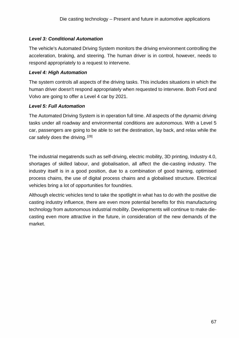
Die casting technology – Present and future in automotive applications
67
Level 3: Conditional Automation
The vehicle's Automated Driving System monitors the driving environment controlling the acceleration, braking, and steering. The human driver is in control, however, needs to respond appropriately to a request to intervene.
Level 4: High Automation
The system controls all aspects of the driving tasks. This includes situations in which the human driver doesn't respond appropriately when requested to intervene. Both Ford and Volvo are going to offer a Level 4 car by 2021.
Level 5: Full Automation
The Automated Driving System is in operation full time. All aspects of the dynamic driving tasks under all roadway and environmental conditions are autonomous. With a Level 5 car, passengers are going to be able to set the destination, lay back, and relax while the car safely does the driving. [28]
The industrial megatrends such as self-driving, electric mobility, 3D printing, Industry 4.0, shortages of skilled labour, and globalisation, all affect the die-casting industry. The industry itself is in a good position, due to a combination of good training, optimised process chains, the use of digital process chains and a globalised structure. Electrical vehicles bring a lot of opportunities for foundries.
Although electric vehicles tend to take the spotlight in what has to do with the positive die casting industry influence, there are even more potential benefits for this manufacturing technology from autonomous industrial mobility. Developments will continue to make die-casting even more attractive in the future, in consideration of the new demands of the market.

Die casting technology – Present and future in automotive applications
68
5 Die casting – future
5.1 Development of die casting
Due to the serious changes in the area of the product portfolio, as well as the increased pressure of cost optimization, technological developments are absolutely necessary.
The requirements that define this for the foundries are enormous. In terms of time, the situation gives no room to move. At the same time, new products must be designed and industrialized at short notice, as well as new processes developed or at least further developed.
A high demand for foundry expertise resources and financial resources is needed in the short term and is also needed in the medium term. This results in the following relevant short-term fields of action: Salt cores, Vacuum die casting, Minimal lubrication, Heat treatment, Alloy development, Additive manufacturing process (currently only interesting for prototype development)
Based on the long-term corporate strategy and the individual know-how level of the foundries, technology roadmaps have to be created and prioritized.
Partnerships with customers, suppliers, universities as well as market companions can save time, money and resources and make the necessary difference at the end of the day. The following tasks are on the agenda:
o The technology roadmap has to be prioritized and focused o The financial base needs to be stabilized. Financial resources are to be secured
in the long term o The need for foundry know-how must be secured o Profitability remains the top priority, regardless of all other projects
5.2 Radical change in die casting foundries
The past few years have been turbulent for foundries. From constantly growing requirements and fluctuating revenues. One of the main drivers of change is the automotive industry, as one of the most important customer of the casting industry.
On the one hand, future projects of the automotive industry such as electromobility require enormous investments. Structural and lightweight design play crucial roles in the realization of these projects. Many lightweight components are already produced as

Die casting technology – Present and future in automotive applications
69
prototypes in 3D printers. OEMs such as BMW or Mercedes-Benz are already using this technology to print spare parts. [43]
On the other hand, the sales of new vehicles are starting to decline, partly due to the diesel scandal. Compared with the previous year, the share of new diesel-powered vehicles fell by more than 13 % in the European market. Constant uncertainties and political discussions upset consumers and prevent them from buying new vehicles.
The rising speed of technological progress and technology adoption is a fact that manufacturers need to face constantly. The automotive sector represents one of the best examples.
Nowadays, we live in an era of connectivity, where new ideas for improvement or new products can fly and reach the consumers without effort. Technological progress is not the only one rising at an exponential rate. Another thing that is also getting faster is the rate at which manufacturers adopt newly commercialized technologies.
The future of die casting companies in general and of Zatorcal´s in particular is expected to receive a huge influence by the new upcoming changes in design and implicitly in the new requirements of the automotive industry.
5.3 Electromobility relies on foundries
Electric motors continue to rely on castings. Yet foundries and die-casting companies still need to prepare themselves for the transformation.
The combustion engine has been standard for a long time now. Electric motors and hybrid propulsion systems present new challenges but also chances to suppliers and manufacturers of engines and engine parts.
At the moment, there are several possible concepts regarding what drive systems will look like in future. Whether it´s the electric engine, the hybrid drive or the fuel cell or the good old combustion engine — powered by CO2-neutral e-fuel (synthetic fuel produced with the help of renewable energy).
Electromobility is broadly considered to be the key to CO2-neutral private transport in the long term. How long the combustion engine will continue to be the transitional solution depends not only on political decision-makers but also and above all on progress in the development of battery technology and on the widespread availability of charging infrastructure. After all, users require a longer range at economic cost.
In the meantime, experts think that combustion engines will be continuing to play a role for a long time in the transition period and afterwards as well. FEV

Die casting technology – Present and future in automotive applications
70
(Foschungsgesellschaft für Energietechnik und Verbrennungsmotoren), an independent development service provider in the automotive field, has conducted a study on e-mobility. According to the results, less than one percent of all vehicles sold globally in 2016 were primarily driven by electricity. The experts expect that the majority of vehicles sold in Europe in 2030 will still have a combustion engine (75 to 85 percent), although most of them (about 90 percent) will be in hybridized powertrains. The global situation does not look any different. Even if there is a strong increase in electrification of the powertrain, most drives will still have combustion engines in 2030 as well. The experts at FEV emphasize that these combustion engines will need to operate in very varied drive topologies. [29]
Professor Hermann Rottengruber from Magdeburg University is certain: “The switch to purely electrical vehicles will be taking place via hybrid drive systems.” He expects a hybrid powertrain with a combustion engine and an electric motor to remain the optimum solution for many different applications and types of vehicles in the long term as well. The motor expert issues a warning, however: “It is nevertheless time to think about how the market for vehicle drive components will be transformed in view of these changes”.
Figure 34. Electronic axle drive with two-speed transmission - presented at IAA 2017 [45]
Nevertheless, traditional production processes will not be obsolete: electromobility will not have a viable future without foundries and steel mills. Major components of the engine, the powertrain and the body of electric vehicles are made from steel or aluminum — either moulded or cast.

Die casting technology – Present and future in automotive applications
71
5.3.1 Electrification of the powertrain
The experience of driving an electric vehicle is powered by a great variety of systems. The reduction in fuel consumption and CO2 emissions, which are the aims of electrification, begin with the comparatively simple automatic start-stop systems based on 12 V electrics and end with a completely battery electric vehicle (BEV) with high-voltage technology.
All of these systems have consequences for the design: Electrification leads to a fundamental change in the powertrain. Consequently, entire supply chains for engine manufacturing need to be rethought completely. While combustion engine drives are dominated by manual and automatic transmissions with up to ten gears, an exclusively electric vehicle manages without complex engines and transmissions. While the engine and transmission of a conventional car consist of about 1,400 parts, an electric motor plus transmission have no more than about 200. [46]
The consequence for foundries of the elimination of combustion engines: no cylinder blocks, no cylinder heads, no pistons, no exhaust and other manifolds. Steel manufacturers lose the production of forged crankshafts, camshafts and complicated transmissions. Yet steel mills and foundries have every reason to be relaxed about such developments. Classic combustion engines and new electric motors will need to be manufactured alongside each other for many more years anyway, which will initially even lead to an increase in components. Moreover, electric vehicles include forged and moulded steel parts and castings as well, so that new opportunities will be created. No battery vehicle moves without highly complex cast and steel components. The battery, electric motor, powertrain and power electronics are the crucial components in electromobility.
Figure 35. Casting and steel: prototyping of the prospective gear of an electric drivetrain [46]

Die casting technology – Present and future in automotive applications
72
5.3.2 Lightweight structures – key factors
The Tesla electric limousine with the longest range (600 kilometers) incorporates a battery that weighs 750 kilograms. Average electric cars have to move batteries weighing between 200 and 300 kilograms. In order for electromobility to reach the mass market in spite of the weight and expense of the batteries, economic lightweight structures are becoming a key technology in automotive manufacturing. Initially, the electric car pioneer Tesla started with a blend of aluminum, titanium and steel, while BMW chose expensive lightweight carbon fiber-reinforced plastic for its electric car i3. Now, a change is apparent thanks to new lightweight steel materials. The new Tesla Model 3 is based mainly on steel and BMW has in the meantime discontinued its joint venture with the carbon manufacturer SGL Carbon. [49]
The need for lightweight structures and the weight reduction associated with electromobility are an encouragement to foundries. Lightweight cast components made from non-ferrous metal – aluminum and, to a lesser extent, magnesium – are becoming increasingly important as rivals to steel and aluminum sheet and profile components for chassis and body parts. Struts and longitudinal bars made from die-cast aluminum make some good examples.
Structural components made from die-cast aluminum represent in general a very interesting combination of weight reduction potential, costs and component properties. In the meantime, structural casting is finding its way into higher-volume, mid-sized vehicle platforms that need to be manufactured in identical quality in several different markets all over the world at the same time.
In the future, interesting business cases for die casting industry in general and Zatorcal company in particular could be control units housings or housing structures for power electronics or electric motor, housing structures for autonomous applications such as lidar or cameras, energy recovery components or parts that build the internal transmission.
5.3.3 Electrical strip – a core material
Both steel and cast products continue to be essential for the engine and powertrain as the switch is made to electric cars. Electromobility is not possible without steel.
The core material for all electric motors is electrical strip. Motor torque depends to a large extent on the quality of the magnetically soft steel product. The iron-silicon alloy determines the efficiency level, which is supposed to be as high as possible, and the energy loss due to demagnetization, which is supposed to be as low as possible.

Die casting technology – Present and future in automotive applications
73
Research and development work in the electrical strip area have not been completed yet, but it has been demonstrated just how much potential the electrical strip technology has.
Figure 36. The electric engine of E-Tron Quattro - the 1st purely electric model by Audi [50]
5.4 The influence of electromobility
5.4.1 Overview
In order to produce light metal castings economically and in a high quality, an "all-in-one" system is essential. The focus thereby is on melting and dosing as well as on heat treatment. This aims to guarantee a high availability of the entire process, and also to take the optimization of individual process steps into consideration. For the melting sector, this means an increase in metal yield. The company relies on targeted temperature and flow control, state-of-the-art burner technologies and minimized excess air. The manufacturer also optimizes the energy efficiency of its melting furnaces by using waste heat. In addition to dosing accuracy and process reliability, the topics of metal yield and energy efficiency are also at the forefront.
During the production of cast aluminum parts for electric cars, special attention is also paid to the final heat treatment. Therefore, all necessary steps can be precisely coordinated. Progressive automation of all processes is intended to ensure that capacities are used optimally at all times, thus saving time, energy and manpower. Affordability remains the most important argument. As long as components made of cast

Die casting technology – Present and future in automotive applications
74
aluminum or magnesium are not only convincing in terms of quality but also remain affordable, strong growth in electromobility can be seen as an opportunity rather than a threat.
Tomorrow´s mobility is associated with the mega-trends of electrification, autonomous driving, additive manufacturing and lightweight construction.
In the case of lightweight electric vehicles, the range can be increased and lateral dynamics can be improved, and when it comes to autonomous driving, for instance, the vehicle weight is closely connected to vehicle safety. The keyword is compatibility. Lightweight construction is the essential and central driver of innovation, as lightweight construction is necessary to be able to meet the' legal regulations. This applies to conventional drive concepts, hybrid drives, e-mobility, connected drive and autonomous driving in passenger cars and commercial vehicles alike.
5.4.2 Forecast of electromobility
If electromobility takes roots, it will have a significant impact on the future sales opportunities of the automotive industry.
Based on the assumption, that the charging infrastructure will be significantly expanded, the analysis of the markets carried out by the Center of Automotive Management from
Gladbach concludes: "E-mobility will prevail and will have serious consequences for the automotive industry in general and the companies organized in the IVG in particular." [51]
Figure 37. The development of electromobility until 2030 (Source: Studie des Center of Automotive Management im Auftrag des Industrieverbands Giesserei-Chemie e. V.) [52]

Die casting technology – Present and future in automotive applications
75
The companies that mainly supply parts for vehicles with internal combustion engines will face these effects.
The same research concludes that automotive industry suppliers need to prepare appropriate strategies to adapt and transform their businesses.
“On the one hand, the result shows that by 2030 still 70 % of the cars will have an internal combustion engine. Secondly, electric engines are also an opportunity for us. For instance, by improving them with the aid of cast parts or by developing solutions for mounting the batteries. Especially because these non-flammable components constitute an important safety feature” concludes Kuhlgatz, Chairman of the Industrieverband Giesserei-Chemie.
Nevertheless, the study concludes that suppliers have to prepare appropriate strategies to adapt and transform their businesses. These include the expansion of their technological know-how, such as about the components required in electric vehicles. Furthermore, diversification strategies including sectors beyond the automotive industry can be suitable to expand their leeway. Finally, companies should increase the depth and breadth of added value in the production of internal combustion engines and thus be among the winners of the consolidation process. “However, in view of the enormous requirements involved in such transformation strategies, companies should not take too long," says study leader Professor Bratzel. Although these developments take place gradually and will only gain momentum at the beginning of the 2020s. [52]
5.4.3 Global market
The most important global markets for vehicles by far are still China, the USA and (western) Europe. These markets also remain decisive for the strategies of global automobile manufacturers. However, while the US and European markets will tend to stagnate in the medium term, China holds further growth potential for passenger cars until 2030. Motorization rates are low, with the population's prosperity expected to increase. Especially as the government sets relatively strict standards. In the next few years, for example, there will be e-car quotas for OEMs and a sales stop for combustion engines. China therefore plays a central role in future strategies. If the battery development is on track and the expansion of the charging station network continues to progress at the same pace, the number of e-cars has the potential to rise to 114 million vehicles until 2030. In the long term, India also holds considerable future potential.
The analysis on the "Market development of electric vehicles until 2030: Germany, EU, USA, and China" provides valid data about the future of the automotive industry for the foundry sector. It shows that the industry is aware of the signs of the times and is preparing for the future. [52]

Die casting technology – Present and future in automotive applications
76
5.5 Technological advances
The changes in the product portfolio and the pressure to optimize costs are forcing foundries to make technological advances. In particular, the technologies below should be considered.
Vacuum die casting is ideally suited for the production of crash-relevant components, as air inclusions are thus avoided. It is believed that the know-how on vacuum die casting could be successfully implemented by joining ventures with suppliers, who could ensure the transfer of knowledge.
Minimal lubrication offers several advantages at the same time. Firstly, water consumption is reduced through the use of minimum lubrication. Secondly, cycle times are also significantly reduced. Moreover, minimal lubrication is also relevant for structural parts, as it increases process reliability.
Rheocasting and thixocasting are becoming more and more important due to increasing demands on components. Also, with SSM Casting, costs and processes can be increasingly optimized for highly stressed castings.
Heat treatment is becoming increasingly important. Higher elongation and tensile strength are particularly important for crash-relevant components.
As structural parts have high elongation requirements, alloy development is an important challenge.
This technology fields have top priority in the short term. Only foundries with expertise in these issues will benefit from the booming market of changing product portfolios. In the medium term, productivity improvements with these technologies are of existential importance.
The currently emerging change in the aluminum foundry industry is far more serious in its effects than anything we have known in recent years. Companies that are unable to cope with the challenges have no market authorization in the medium or short term.
Foundries need to adapt their business model to the new situation and take the following steps:
o the corporate strategy of the foundries must be revised with regard to internationalization and the emergence of new products.
o new technologies, such as vacuum die casting, heat treatment or alloy development, must be illuminated and possibly incorporated into the technology roadmap.
o foundries corporate culture must be geared to the new requirements

Die casting technology – Present and future in automotive applications
77
o implementation of new technologies requires high investments, which in turn require sufficiently qualified personnel. To this end, the foundry's cost base urgently needs to be optimized.
o for fast and efficient knowledge acquisition, foundries should enter into partnerships. This can facilitate market entry into new product or technology fields.
o foundries have to secure long-term financing to make new investments through a financing roadmap that could help with the implementation.
o despite all the changes, management quality should be given the highest priority.
5.6 Changes in foundries product portfolio
Die casting is an economic method for the manufacture of structural components in which foundries are confronted with numerous challenges. Modern manufacturing technologies and cooperation with other companies strengthen their competitiveness.
New technologies, such as E-mobility, create new products. The previous "bread and butter" parts, engine and gearbox disappear. In particular chassis and structural parts are becoming increasingly important. Many of the vehicle components that were made of steel some time ago are now largely made of light metals. Machining large structural components requires die casting machines with high clamping forces. However, the demand for die casting machines with high clamping forces is higher than the previous supply. These changes in the product portfolio, internalization, appearance of new technologies and the recruitment of qualified personnel present foundries with new challenges, such as high costs in case of acquisition of larger die casting machines, high expenses during new product launches, losses in earnings because of falling demand for previous core products and the already declared competition.
Changes in the product portfolio can be seen as both an opportunity and a risk. The foundries that will be able to seize the opportunity are the ones with the appropriate technology, prepared employees, financial strength and clear strategy.
Specialists expect that the market for structural castings will continue to grow strongly in the coming years. The general global demand for automotive die castings is expected to increase from more than € 6.7 billion in 2015 to nearly € 11 billion in 2021 with an estimated average annual growth rate (CAGR) of more than 7.8% in the period from 2016 to 2021. [47] One of the strengths of die casting technology is that die casting processes enable in one operation step the manufacture of parts which can combine different geometries, partially reinforced or thinned wall thicknesses and various functions.

Die casting technology – Present and future in automotive applications
78
The automobile industry is undergoing a period of transition in terms of drive technology. It´s difficult to predict where this change will end. However, it seems already clear that suppliers which manufacture only components for combustion engines and conventional powertrains will lose market segments. On the other hand, vehicles with hybrid, electric, fuel-cell or other "alternative" drives require special components, such as battery housings, which can be optimally manufactured by die casting. Vehicles with hybrid drive need also a weight compensation because they have two drive systems. Also, for this purpose, die castings are very suitable. Last but not least, as every motor vehicle irrespective of its drive requires structural parts, there are good market opportunities for die casting foundries in this field also in the future.
Light metals, such as aluminum and magnesium are used in die casting manufacturing of structural components like modern automotive bodies and chassis. Die casting can reliably produce these parts while also meeting important crash strength requirements, lightweight objective and being entirely recycled once it reaches its life end.
Figure 38. Subaru e-BOXER, hybrid vehicle as seen in Automobile Barcelona Motor Show, 2019
Weight reduction and E-mobility have an enormous influence in the CO2 reduction. As a result of this development, the aluminum foundry industry will experience the biggest change in the product portfolio of the past 100 years.
The die casting industry needs to prepare itself for the ambitious future prospects. High performance equipment built with innovative technology needs to be used to reach positive effects on productivity and competitivity.

Die casting technology – Present and future in automotive applications
79
For the past 50 years, the growth of the aluminum foundry industry has been characterized by the substitution of different engine and gearbox components by aluminum castings. Automobile engine blocks and truck gearboxes were the last significant parts from the early 1980s, which led to significant market growth in the field of aluminum casting. Meanwhile, this substitution is completed in principle. In addition to Europe, all other regions worldwide have now followed suit. In the engine and transmission sector, no increases in the aluminum casting requirement due to substitution are expected.
The main drivers of automotive industry that will contribute to the revolution in the product portfolio of aluminum foundries are autonomous driving, car-sharing, digitalization and electrification.
Previous conventional parts, such as engine and transmission will disappear, but new parts in the powertrain will be created. Together with the growth market of chassis and structural parts, there is the potential to generate growth in the area of die casting in the next few years, despite this dramatic change.

Die casting technology – Present and future in automotive applications
80
6 New business cases
6.1 Effects of electromobility on vehicle architecture
The elimination of the internal combustion engine and the integration of the heavy battery in electric vehicles have a great impact on vehicle architecture. In order to compensate for this change in terms of weight, new technologies and materials are introduced to body construction.
Electromobility presents opportunities for new concepts and innovation. Companies see opportunities for incorporating new technologies such as additive manufacturing processes and for automotive lightweight design or for electric motors manufacturers to entry into the automotive industry market.
The effects of electromobility on the supply chain are just as severe. All components of the combustion engine (a four-digit number of components) become obsolete, as are auxiliary units such as the tank and exhaust system. The (usually two-stage) gearbox is much simpler in design or is completely omitted. Braking and steering systems as well as the wheel suspension are changing significantly, as are, for example, the heating/air conditioning. At the same time, additional electrical and electronic components are required.

Die casting technology – Present and future in automotive applications
81
Figure 39. New components in a hybrid vehicle. Subaru Hybrid e-BOXER as seen in Automobile Barcelona Motor Show, 2019
Electric mobility will result in significant changes in the supplier industry. Therefore, in order to remain market leaders, automotive suppliers need to accelerate their strategy change towards e-mobility and update their product portfolio.
The economic effects should also not be underestimated. According to a study conducted by the Institute for Labor Market and Occupational Research in December 2018 [48], almost 100,000 jobs will be lost in Austria due to the switch to electric drive systems for passenger cars. The main reason for this is the much simpler design of the drive train.
Plenty of castings from foundries are also common in electric cars. Foundries will be producing battery housings made of aluminum with an integrated cooling system for car manufacturers. The additional growth is being generated by the change in drive concepts and the introduction of new structural electromobility components like battery housings to begin with.
Electric drive systems for cars require a large number of new components. Besides housings for batteries, these are, first and foremost, housings for electric motors and power electronics, which are designed preferably as castings due to their complexity.
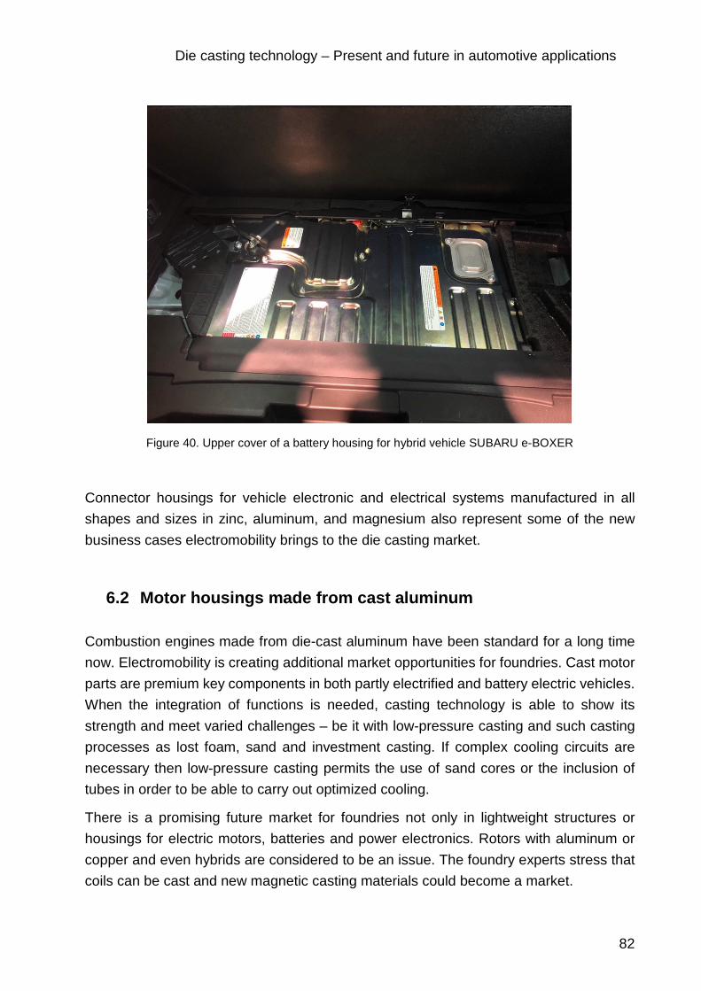
Die casting technology – Present and future in automotive applications
82
Figure 40. Upper cover of a battery housing for hybrid vehicle SUBARU e-BOXER
Connector housings for vehicle electronic and electrical systems manufactured in all shapes and sizes in zinc, aluminum, and magnesium also represent some of the new business cases electromobility brings to the die casting market.
6.2 Motor housings made from cast aluminum
Combustion engines made from die-cast aluminum have been standard for a long time now. Electromobility is creating additional market opportunities for foundries. Cast motor parts are premium key components in both partly electrified and battery electric vehicles. When the integration of functions is needed, casting technology is able to show its strength and meet varied challenges – be it with low-pressure casting and such casting processes as lost foam, sand and investment casting. If complex cooling circuits are necessary then low-pressure casting permits the use of sand cores or the inclusion of tubes in order to be able to carry out optimized cooling.
There is a promising future market for foundries not only in lightweight structures or housings for electric motors, batteries and power electronics. Rotors with aluminum or copper and even hybrids are considered to be an issue. The foundry experts stress that coils can be cast and new magnetic casting materials could become a market.

Die casting technology – Present and future in automotive applications
83
6.3 New drive concepts with formed steel and die-casting
Another component that will still be needed for the drive technology of electric vehicles is the transmission, and thus highly complex die-cast aluminum components as well as equally complex steel components manufactured via forming technology.
The established manufacturing segment for conventional powertrains is already being substituted in the hybridization of existing drive concepts up to and including completely integrated electric drive modules. Some existing components will be eliminated entirely in future, while other components such as control units for power electronics will be integrated directly into the transmission. The product range will be extending more and more in the coming years. The expert lists such components as internal transmission parts, housing structures for electromobility applications, housing structures for power electronics, electric motor housings, energy recovery components and fuel cell stacks.
6.4 Vehicles with cameras instead of typical side-view mirrors
The first Ford Model T marked the beginning of automotive industry and the assembly line in 1908 in Detroit. Ever since, nearly all the components of the automobiles went through dramatic changes and evolution. Car body is more aerodynamic, engines are more and more efficient and powerful and modern electronic systems that make today´s driving easier. There is still one part that didn´t suffer major changes. The element in question is the old-fashioned car mirror. Many automakers are considering replacing it altogether.
A digital alternative to the side-view and rear-view mirrors is foreseen to be adopted by the car manufacturers. The new digital outer and inner mirror system consists of replacing the side-view mirrors with small cameras and introduce in-car display monitors on both sides for a better visibility.
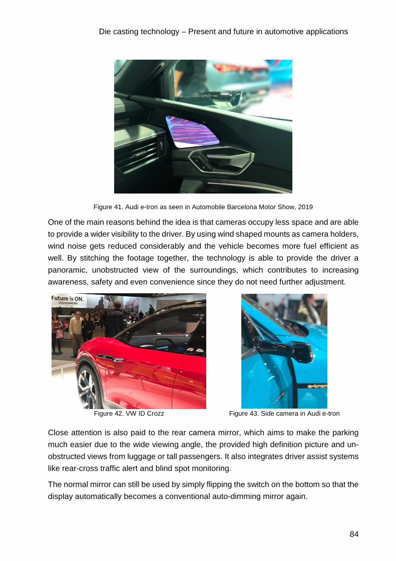
Die casting technology – Present and future in automotive applications
84
Figure 41. Audi e-tron as seen in Automobile Barcelona Motor Show, 2019
One of the main reasons behind the idea is that cameras occupy less space and are able to provide a wider visibility to the driver. By using wind shaped mounts as camera holders, wind noise gets reduced considerably and the vehicle becomes more fuel efficient as well. By stitching the footage together, the technology is able to provide the driver a panoramic, unobstructed view of the surroundings, which contributes to increasing awareness, safety and even convenience since they do not need further adjustment.
Figure 42. VW ID Crozz Figure 43. Side camera in Audi e-tron
Close attention is also paid to the rear camera mirror, which aims to make the parking much easier due to the wide viewing angle, the provided high definition picture and un-obstructed views from luggage or tall passengers. It also integrates driver assist systems like rear-cross traffic alert and blind spot monitoring.
The normal mirror can still be used by simply flipping the switch on the bottom so that the display automatically becomes a conventional auto-dimming mirror again.

Die casting technology – Present and future in automotive applications
85
Figure 44. Digital rear view camera
Among the automobile manufacturers that plan on adopting this design, can be named: BMW, Nissan, Tesla, Toyota, Cadillac. All of them have already experimented with similar systems in recent years.
The image below represents an accurate example of the improvement when it comes to the driving experience. The inner display is able to show a clear image captured by the camera even in bad weather conditions, such as rain or during night driving. The devices are shaped to keep water droplets from hampering the view and similarly to the conventional mirrors, they have embedded heaters in order to prevent fogging on the lens. This new design also offers a wider view when backing up or during turns.
Figure 45. Conventional technology (low visibility during rain) versus new technology (high visibility) [49]
Display monitors are attached at the foot of the front pillars for an easy transition for the driver.

Die casting technology – Present and future in automotive applications
86
Even though the car manufacturers embrace the new camera mirrors, and more and more self-driving features begin to proliferate across automaker ranges, the conventional ones are not yet headed to the scrapyard. They will still continue to have their place in the entry-level automotive industry, at least for some time.
When automotive industry adopts a new technology, it rarely goes back to the one already replaced. Therefore, it is not difficult to envision a near future where reflective glass mirrors are left behind.
As these systems remain costly, they are limited to high-end models for the time being. The digital display systems are expected to aid development of next-generation technologies like autonomous driving. [50]

Die casting technology – Present and future in automotive applications
87
6.5 KERS
A fuel-operated internal combustion engine efficiency even in today’s world is just about 35%. [51] This means a considerable amount of energy is lost due to various inefficiencies in the vehicle system. Heat loss due to heat dissipation from various components is one of the major contributors to reduced vehicle efficiency.
A kinetic energy recovery system, also known as KERS, is an automotive system for recovering a moving vehicle's kinetic energy under braking. In cars that do not present this system, during braking, energy is wasted because kinetic energy is mostly converted into heat energy or sometimes sound energy that is dissipated into the environment. Vehicles with KERS are able to harness some of this kinetic energy. Its potential as a device that increases the overall efficiency of a modern car is tremendous.
The recovered energy is stored in a reservoir (for example a flywheel or high voltage batteries) for later use under acceleration. It is able to release this stored energy back into the drive train of the vehicle, giving an extra power boost to the vehicle. The new brake-by-wire system interacts with the energy recovery system and reduces fuel consumption and emissions by recovering kinetic energy under braking. It is able to improve fuel economy by 15 per cent. [51]
KERS system is rather simple. It requires a component for generating the power (the MGU), one for storing it (the battery/flywheel) and another to control it all (the PCU). The entire assembly weighs in at just around 28kg. [51] This keeps the overall weight of the car really low.

Die casting technology – Present and future in automotive applications
88
Figure 46. Illustration of working principle of KERS [30]
KERS was also adopted in Formula 1 cars. The original KERS was a small and light device designed to meet the FIA regulations for the 2009 Formula One season. Racing teams started developing and using it in their F1 cars which made them have a power advantage. This was seen as a major problem by the F1 Rules & Regulations Board. Though the F1 regulators did not ban this technology, the companies came to a mutual agreement to do without it and stick to regular racing.
When a car breaks, it dissipates a lot of kinetic energy as heat. Braking in sports car produces upwards of 700 degrees C. The KERS tries to store this energy and converts this into power that can be used to boost acceleration. A standard KERS operates by a ‘charge cycle and a ‘boost cycle’. As the car slows for a corner, an actuator unit captures the waste kinetic energy from the rear brakes. This collected kinetic energy is then passed to the storage unit. The storage unit is positioned centrally to minimize the impact on the balance of the car.
MGU (motor/generator unit)
While a motor-generator set may consist of distinct motor and generator machines coupled together, a single unit motor-generator will have both rotor coils of the motor and the generator wound around a single rotor, and both coils share the same outer field coils or magnets working in two modes, the MGU both creates the power for the batteries when the car is braking, then return the power from the batteries to add power directly to the engine, when the KERS button is deployed.

Die casting technology – Present and future in automotive applications
89
PCU (power control unit)
It serves two purposes, firstly to invert & control the switching of current from the batteries to the MGU and secondly to monitor the status of the individual cells with the battery. Managing the battery is critical as the efficiency of a pack of Li-ion cells will drop if one cell starts to fail. A failing cell can overheat rapidly and cause safety issues. As with all KERS components the PCU needs cooling.
Batteries become hot when charging them so many of the KERS cars have more cooling ducts since charging will occur multiple times throughout a race. Super-capacitors can also be used to store electrical energy instead of batteries; they run cooler and are debatably more efficient.
Figure 47. KERS System Layout [52]
Housings for the energy storage device and for the ECU represent possible business cases for the die casting manufacturing industry.
It’s a technology for the present and the future because it’s environment-friendly, reduces emissions, has a low production cost, increases efficiency and is highly customizable and modifiable, it is light weight and small sized, is a long-life system. That could reach
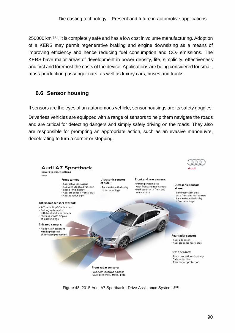
Die casting technology – Present and future in automotive applications
90
250000 km [30], it is completely safe and has a low cost in volume manufacturing. Adoption of a KERS may permit regenerative braking and engine downsizing as a means of improving efficiency and hence reducing fuel consumption and CO2 emissions. The KERS have major areas of development in power density, life, simplicity, effectiveness and first and foremost the costs of the device. Applications are being considered for small, mass-production passenger cars, as well as luxury cars, buses and trucks.
6.6 Sensor housing
If sensors are the eyes of an autonomous vehicle, sensor housings are its safety goggles.
Driverless vehicles are equipped with a range of sensors to help them navigate the roads and are critical for detecting dangers and simply safely driving on the roads. They also are responsible for prompting an appropriate action, such as an evasive manoeuvre, decelerating to turn a corner or stopping.
Figure 48. 2015 Audi A7 Sportback - Drive Assistance Systems [53]
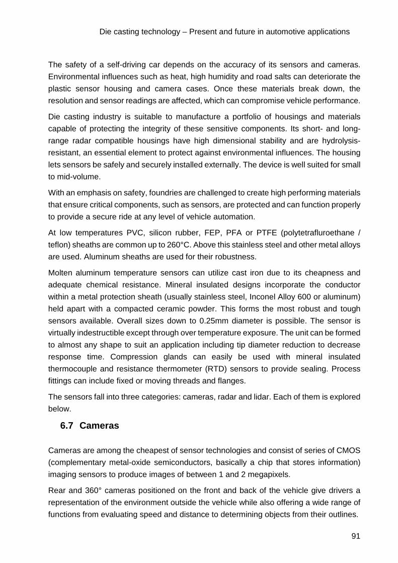
Die casting technology – Present and future in automotive applications
91
The safety of a self-driving car depends on the accuracy of its sensors and cameras. Environmental influences such as heat, high humidity and road salts can deteriorate the plastic sensor housing and camera cases. Once these materials break down, the resolution and sensor readings are affected, which can compromise vehicle performance.
Die casting industry is suitable to manufacture a portfolio of housings and materials capable of protecting the integrity of these sensitive components. Its short- and long-range radar compatible housings have high dimensional stability and are hydrolysis-resistant, an essential element to protect against environmental influences. The housing lets sensors be safely and securely installed externally. The device is well suited for small to mid-volume.
With an emphasis on safety, foundries are challenged to create high performing materials that ensure critical components, such as sensors, are protected and can function properly to provide a secure ride at any level of vehicle automation.
At low temperatures PVC, silicon rubber, FEP, PFA or PTFE (polytetrafluroethane / teflon) sheaths are common up to 260°C. Above this stainless steel and other metal alloys are used. Aluminum sheaths are used for their robustness.
Molten aluminum temperature sensors can utilize cast iron due to its cheapness and adequate chemical resistance. Mineral insulated designs incorporate the conductor within a metal protection sheath (usually stainless steel, Inconel Alloy 600 or aluminum) held apart with a compacted ceramic powder. This forms the most robust and tough sensors available. Overall sizes down to 0.25mm diameter is possible. The sensor is virtually indestructible except through over temperature exposure. The unit can be formed to almost any shape to suit an application including tip diameter reduction to decrease response time. Compression glands can easily be used with mineral insulated thermocouple and resistance thermometer (RTD) sensors to provide sealing. Process fittings can include fixed or moving threads and flanges.
The sensors fall into three categories: cameras, radar and lidar. Each of them is explored below.
6.7 Cameras
Cameras are among the cheapest of sensor technologies and consist of series of CMOS (complementary metal-oxide semiconductors, basically a chip that stores information) imaging sensors to produce images of between 1 and 2 megapixels.
Rear and 360° cameras positioned on the front and back of the vehicle give drivers a representation of the environment outside the vehicle while also offering a wide range of functions from evaluating speed and distance to determining objects from their outlines.

Die casting technology – Present and future in automotive applications
92
Most cameras are 2D but some manufacturers – especially luxury class car makers – are beginning to incorporate 3D cameras too. Both 2D and 3D camera need sensors with a very high dynamic range of more than 130 dB, which is necessary to ensure a clear image even with direct sunlight on the lens.
Cameras (as opposed to lidars, radars and ultrasonic sensors) are passive sensors that collect light reflected from the environment. While cameras offer a higher resolution, their data is subject to a variety of environment influences, such as: fog, rain, sun, snow, dust, darkness etc. Camera data needs to be interpreted by computer vision algorithms in order to provide useful information for autonomous driving, while the data from distance measuring sensors such as lidar can be used for collision avoidance. On the positive side camera data (once interpreted) provides the semantically richest representation of the vehicle’s environment.
Figure 49. New camera system in the rear side of the car, model Volkswagen ID Cross (Showroom Auto show Barcelona, 2019)
Cameras in modern vehicles represent a great opportunity for die casting foundries because they are able to build die cast aluminum housings that have a high impact resistance, can have an adjustable sliding tray design and can have entry glands for cables and mounting holes on the bottom of the housing.

Die casting technology – Present and future in automotive applications
93
6.8 Radar
Radar or radio detection and ranging – uses radio waves to detect and localize objects. Electromagnetic waves are emitted, hit and bounce back from an object, and are detected upon their return, to provide information about an object’s location and speed.
Current systems are based on short-wave sensors at 24 GHz or longer wave at 77 GHz. Both sensors are used at the front and back of the vehicle to monitor surrounding traffic ranging from a just few centimeters to hundreds of meters away. The shorter-range sensors are found on the corner of the vehicle and are designed to support highly automated driving; as such they are generally used for blind spot detections, parking assist and emergency braking for example. The longer-range sensors are forward facing and placed at the front of the vehicle; they offer higher accuracy for speed and distance measurements, more precise angular resolution, have a smaller antenna size and therefore lower interference problems.
The electronics involved, however, represent only a part of the aspects that need to be considered. While designing the radar system, a major focus needs to be put on the protection of the radar electronics and of the antenna. The material properties and the design need to be analyzed carefully during the selection of the housing.
The first factor to consider is how the housing might affect the radar performance in relation to the antenna. Any type of material, when placed besides the antenna affects the emitted radiation pattern. Most of the electronics enclosures already on the market are made of polymers. These have the potential to interfere with the RF transparency of the housing. Therefore, ensuring have the compatibility between the radar frequency and the material properties of the housing is a crucial step when designing a sensor. Thus, new materials need to be accounted for radar and antenna housings.
The next important thing to consider during the housing design concept creation phase is the mechanical performance and the physical configuration of the housing. In the necessity of performing various functions simultaneously, it might lead to making technical trade-offs. The primary consideration, however, is the protection of the electronics and antenna from the environment factors, such as vibration, shock, moisture, light exposure and temperature variations, dust and aggressive chemicals. The challenge comes during exposure to extreme temperatures; the housing must either keep electronics cool or heat them in order to keep them in their optimum temperature range.
Another challenge the physical design of the housing might face is to reach the barrier of being robust enough to prevent theft or tampering, but also allow easy mounting or servicing of the system without interfering with its performance.

Die casting technology – Present and future in automotive applications
94
By combining these features, die casting industry is able to build high performance radar sensing housing solutions.
6.9 Lidar
Lidar - or light detection and ranging – was developed shortly after the advent of lasers in the 1960s, and was first used to measure clouds. It is perhaps the most significant piece of hardware in the contest to develop self-driving cars. Lidar shoots rapid pulses of ultraviolet (UV), visible or near infrared (IR) laser light at a surface – up to 150,000 pulses a second – and measures the time taken for the pulse to bounce back from the target. The distance to the object is deduced by using the speed of light to accurately calculate the distance travelled. The result is an accurate three-dimensional picture of the target object and its surface characteristics.
Google and Uber are among the many names developing autonomous vehicles: their roofs feature a continuously spinning box which gives 360° visibility and precise, in-depth data about the exact distance to an object to an accuracy of ±2 cm [54]. This box is the lidar system and consists of a laser, scanner and optics and a specialized GPS receiver, which is especially important if the system is moving. Huge 3D maps are generated for the vehicle to navigate through, while pedestrians and cyclists, traffic signs and other nearby obstacles are also detected.
However, each sensor technology is not without its pitfalls and it is likely a combination of the three will be necessary to make a safe, truly autonomous vehicle.
The general physical requirements of the lidar system are to be robust, compact, stable, easy to operate, remote control, low weight and cheap to maintain.
Among the lidar housing physical properties can be listed: it needs to be compact, weather-proof, protect from solar radiation and to be able to control temperature-humidity.

Die casting technology – Present and future in automotive applications
95
7 Alternative technologies to die casting
Injection moulding is the most well-known plastic-moulding process and is used to produce nearly one-third of all plastic components. However, other moulding processes such as thermoforming, rotational moulding, or blow moulding, to name a few, offer significant cost advantages, provide better structural capabilities, and can make larger parts compared to injection moulding.
Alternative moulding processes can produce hollow, multi-colored or multi-layered components which are often bigger, stronger, and less costly than their injection molded counterparts.
7.1 Alternatives to injection molding
Low-pressure molding
Gas-assist moulding — an extension of injection moulding, gas-assist partially fills the mould with material in what is commonly referred to as a “short-shot.” Near the end of polymer fill, nitrogen is injected into the system. The gas bubble forces the polymer deep into mould cavities, hollowing out channels as it travels through the material. Nitrogen is either injected via the same nozzle as the polymer, into the mould cavity by way of runners, or directly into the part or rib sections. Multi-nozzle gas fill is called web moulding. Moulders must design both the part and nozzle’s location carefully to optimize the flow patterns of the gas. Otherwise gas bubbles will follow the path of least resistance and may bleed into thin areas.
The biggest advantage of gas-assist is that the resulting hollow channels boost stiffness without adding weight. Gas-assist can produce large parts with large cross sections that once were considered impractical for moulding. Other benefits of gas-assist include reduced cycle times, more uniform packing with reduced stress, less part warpage, and less sink marks.
Structural-foam moulding
Constructed of foam core encased in a solid skin, structural-foam-moulded parts have higher strength to- weight ratios than those made by conventional injection moulding. Skin-core construction improves load bearing performance by up to 70%. Structural foam is made either by introducing inert gas into the melt or pre-blending a chemical blowing agent into the resin. The resin/gas mixture is injected into the mould, in a short-shot. The

Die casting technology – Present and future in automotive applications
96
pressure from the gas expands the resin into the rest of the mould. Structural-foam parts have low moulded-in stress because short-shots do not require high-pressure packing of the mould. Tooling costs may be lowered by 10 to 20%. The process additionally uses a low clamp tonnage. Which makes larger parts or multicavity moulds practical.
Structural foam provides good dimensional control. Inserts such as brackets, threaded fasteners, or structural supports are easily moulded-in and eliminate costly secondary assembly operations. The process also reduces sink marks on part surfaces even when designs incorporate large ribs, bosses, standoffs, or mounting pads. Sink marks and warpage are also not as prevalent even when parts with relatively thicker walls of 0.25 to 0.125 in. are moulded.
The primary disadvantage of the process is a characteristic swirl-patterned surface. When surface cosmetics are a priority, structural-foam parts need secondary sanding and painting operations to get the same quality as injection moulding. The process also requires longer cycle times because of thicker walls and foam’s insulating properties.
Co-injection moulding
Also called sandwich moulding, co-injection uses a specially designed nozzle to inject two materials into a mould so that one completely encapsulates the other. Several constructions are possible. The most common are composites with either a solid-skin/solid-core or solid-skin/foam-core.
Co-injection moulding provides an aesthetic surface. Solid skin/ solid-core gives a rigid part while maintaining a nice looking or flexible surface. Apart from the multi-material use possibility advantages of solid-skin/foam-core include thick walls with injection quality surfaces, no sink marks, and good rigidity at less cost.
Material selection for co-injection, however, is critical. Core and skin material must shrink and expand at the same rate and be compatible. Viscosity of the materials must also match up well. Typically, the skin is a lower viscosity material and lets higher viscosity core materials flow through its center. Use of recycled core material and a quality surface make this process attractive. However, there are some economic hurdles. For one thing, the capital equipment required costs 50 to 100% more than that of injection moulding.
In-mold polymerization
Reaction-injection moulding (RIM) — In-mould polymerization lets RIM form large parts with 10 to 15% less injection pressure and less than 5% of the clamping force used in conventional injection moulding.

Die casting technology – Present and future in automotive applications
97
RIM starts with two low viscosity components, that when mixed and injected into the closed mould, quickly react and polymerize. The low pressures needed to mould the low-viscosity components produce complex geometries with no moulded-in stresses and little shrinkage. It accepts inserts or stiffeners and readily duplicates mould surfaces. The low-pressure, slow-cavity fill also handles walls whose thickness varies. Ribs and bosses can be moulded without the threat of sink marks, and the process can accommodate in-mould coating which reduces finishing costs.
Polyurethane remains the dominant RIM material. Designers can tailor part structural properties through judicious selection of its different families. Elastomeric urethanes exhibit good impact resistance, while solid urethane RIMs can be made to resist static build-up or can be flame retardant. Other varieties of urethane include RIM foams which range from flexible to rigid. Like other engineered resins the RIM polyurethanes accept fillers or other reinforcements. The resulting processes are commonly referred to as RRIM (reinforced RIM) or SRIM (structural RIM).
RRIM combines short-fiber or flake reinforcement directly into the reaction process, while SRIM uses moulds containing structural preforms. Preforms are three-dimensional precursors of the part and can be plastic or metallic inserts, fibrous reinforcements, or core materials. The most common preforms are fiberglass and can be mats of either thermoformed continuous strands or chopped fibers sprayed onto part-shaped screens.
Contoured in-mould cores, sometimes referred to as the male, hollow out three-dimensional SRIM parts giving thicker profiles and reduced weight. Metallic inserts provide localized stiffening, attachment points for high stress areas, and weldable studs. SRIM uses urethanes similar to those of RIM. However, the SRIM resins must have lower viscosities in order to better penetrate the preforms.
Blown up or spun around - Technical blow moulding
Blow moulding produces lightweight parts with the highest stiffness-to-weight ratio of any thermoplastic process. It starts with a hollow tube of material (parison) extruded between open mould halves. As the mould closes, the parison is grasped and pinched off at each end. Air injects through a blow pin, expanding the parison into the mould cavity, where it solidifies and takes shape.
Blow-moulded parts have lower moulded-in stresses than injection-molded components. Consequently, there is less warpage and fewer failures from stress. This single-operation process easily moulds complex parts or flat panels. The technique employs foam filling, moulded-in stiffeners or compression welds — tack offs — between opposite sides of the parison to boost stiffness and strength in flat panels.
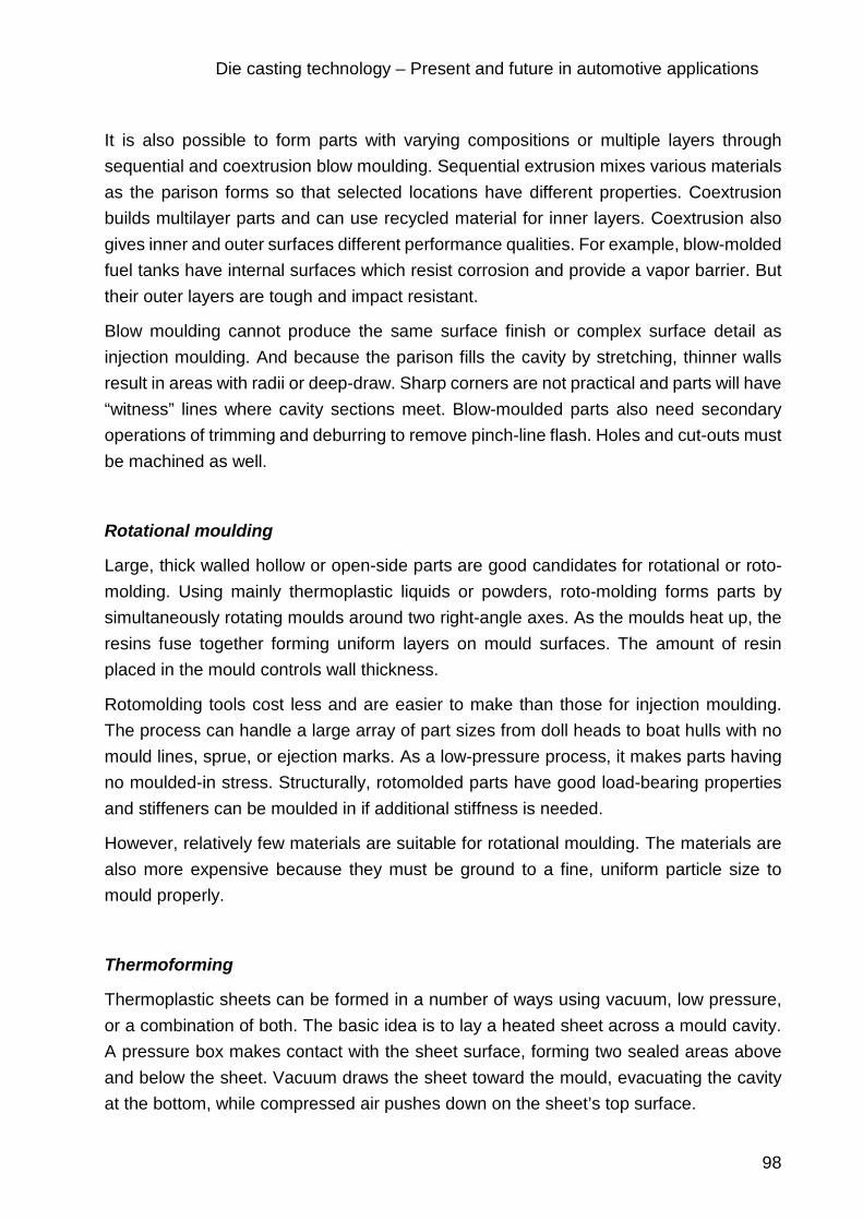
Die casting technology – Present and future in automotive applications
98
It is also possible to form parts with varying compositions or multiple layers through sequential and coextrusion blow moulding. Sequential extrusion mixes various materials as the parison forms so that selected locations have different properties. Coextrusion builds multilayer parts and can use recycled material for inner layers. Coextrusion also gives inner and outer surfaces different performance qualities. For example, blow-molded fuel tanks have internal surfaces which resist corrosion and provide a vapor barrier. But their outer layers are tough and impact resistant.
Blow moulding cannot produce the same surface finish or complex surface detail as injection moulding. And because the parison fills the cavity by stretching, thinner walls result in areas with radii or deep-draw. Sharp corners are not practical and parts will have “witness” lines where cavity sections meet. Blow-moulded parts also need secondary operations of trimming and deburring to remove pinch-line flash. Holes and cut-outs must be machined as well.
Rotational moulding
Large, thick walled hollow or open-side parts are good candidates for rotational or roto-molding. Using mainly thermoplastic liquids or powders, roto-molding forms parts by simultaneously rotating moulds around two right-angle axes. As the moulds heat up, the resins fuse together forming uniform layers on mould surfaces. The amount of resin placed in the mould controls wall thickness.
Rotomolding tools cost less and are easier to make than those for injection moulding. The process can handle a large array of part sizes from doll heads to boat hulls with no mould lines, sprue, or ejection marks. As a low-pressure process, it makes parts having no moulded-in stress. Structurally, rotomolded parts have good load-bearing properties and stiffeners can be moulded in if additional stiffness is needed.
However, relatively few materials are suitable for rotational moulding. The materials are also more expensive because they must be ground to a fine, uniform particle size to mould properly.
Thermoforming
Thermoplastic sheets can be formed in a number of ways using vacuum, low pressure, or a combination of both. The basic idea is to lay a heated sheet across a mould cavity. A pressure box makes contact with the sheet surface, forming two sealed areas above and below the sheet. Vacuum draws the sheet toward the mould, evacuating the cavity at the bottom, while compressed air pushes down on the sheet’s top surface.

Die casting technology – Present and future in automotive applications
99
Similarly, hollow parts are made using a twin-sheet forming process. Two opposing moulds come together with the heated sheets between them. Vacuum draws each sheet to the corresponding mould half, while compressed air is introduced between them. Ballooning out, the sheets take the shape of the mould and fuse together where the moulds meet. Vacuum can also be used alone to draw thermoplastic sheets into female moulds or over male ones.
At low volumes, thermoforming produces near-injection moulded quality. Thermoforming tooling is also less costly, less complicated, and easier to make than injection-moulding tools. It is a process that makes economic sense for the small production runs, when compared to other moulding techniques such as injection moulding.
Materials for thermoforming are more expensive because they have already been processed into sheet form. Finished parts also require secondary trimming or routing for holes, louvers, or grills. Robotic trimmers, however, have reduced the cost of these operations so thermoforming prices, especially at low volumes, are comparable to injection moulding.
Compression moulding
Here matched male and female dies close around a “charge” of material filing the cavity. The pressure and heat inside the mould cure the resin. One of the most common thermoset materials is sheet-moulding compound (SMC). It consists of 20 to 25% glass fibers, uncured thermoset resin, and thickeners sandwiched between carrier films. Before moulding, the carrier films are removed and the SMC is placed in the bottom mould where it is compressed as the moulds come together. Moulded openings are possible by the use of shear edges or “mash-offs.” As the moulds come together, the mash-off technique squashes the material in selected locations to a membranelike thickness. A secondary process cuts the membrane from the part. Holes created by mash-off give the parts less stress in the surrounding material.
SMC is a low-pressure process and can use less robust tools made from materials such as reinforced thermosets for low-volume components that do not require shear edges or slides. Reinforced SMCs have good strength-to-weight ratios and tight tolerances, but low-impact resistance. The biggest disadvantage is the refrigeration storage requirements and shelf life of the SMC.
Glass Mat Thermoplastic (GMT)
Moulded composites made of reinforced thermoplastic sheets offer advantages for large parts when compared to SMCs, wood, or steel. The preheated, reinforced thermoplastic sheets are laminated together in a single mould. Often called stamping, it differs from

Die casting technology – Present and future in automotive applications
100
conventional steel stamping because it forms parts in just one operation instead of the progressive steps required by steel. The ability to laminate layers of varying reinforcement, continuous, unidirectional, and chopped fibers, make it extremely flexible. When compared to SMCs, thermoplastic moulding produces less scrap and has shorter cycle times. The thermoplastic material also has an indefinite shelf life.
Threaded fasteners, steel-edge stiffeners, and sheet metal plates are easily moulded-in. Dissimilar, decorative materials such as fabrics or carpet can also be laminated-in with proper temperature and mould pressures. The technique also easily produces textured mould surfaces.
7.2 Metal casting processes [55]
Metal soft tool die casting
The term “Soft Tool” is used to describe a metal casting tool made out of P-20 steel. The P-20 steel is softer than H-13 steel and thus yields parts in less time with a decrease in tooling cost. This is attributed to the ability to run faster feed rates when CNC machining the tool. Typically, a P-20 metal casting tool can yield 10,000-40,000 castings before showing any significant wear.
Metal permanent mould casting
Permanent mould casting is an excellent solution for low volume metal casting requirements (1,000-5,000). A permanent mould casting looks very similar to a die casting. The main benefit of permanent mould casting compared to a die casting is a significant reduction in tooling cost.
Metal sand casting
Sand casting can be a good fit for low to mid volume production. Metal casting requirements and often the most cost effective for larger components.
Metal RP investment casting
Metal RP (Rapid Prototype) investment casting can be an excellent alternative to CNC machined, SLA, or SLS prototypes. RP investment casting is the only metal casting process that is both cost effective at low quantities and yields metal casting properties.
Metal investment casting
Production investment casting can be an excellent fit for mid to high metal casting quantity requirements. It is good for casting requirements when the geometry cannot be made using other metal casting processes. Compared with RP investment casting, production investment cast metal casting requires a higher upfront investment with a much lower

Die casting technology – Present and future in automotive applications
101
reoccurring metal casting cost. Investment cast metal casting has fewer design constraints than traditional cope and drag metal casting processes.
Metal plaster casting
Metal plaster casting is a very similar process to sand casting, but yields a much better metal casting surface finish which is very similar to a die casting finish. Plaster casting is often used for metal casting quantities of 50-300 to prototype a future die casting. Plaster casting also has the capability of metal casting wall thicknesses as thin as 0.8mm.
7.3 Hybrid additive manufacturing
3D printing without post-processing is a new technology offered by generative manufacturing processes. Additive manufacturing opens up completely new technical and economic opportunities. The disadvantage of usual 3D printing processes is that the components have to be reworked. This hybrid technology enables the production of thin and deep geometries such as ribs, so that the parts can be manufactured without the need for a complex erosion process. [56]
This also reduces the design effort for the injection mould, as there is no need to develop electrodes for eroding. The time and effort involved in creating the various NC machining programs is also eliminated. Depending on the component, it is possible to reduce the lead time from design to the finished mould by 50 % with hybrid additive manufacturing.
Another major advantage of hybrid additive manufacturing is weight reduction. The best example of this comes from the production of a certain part for the housing of the milling spindle conventionally. Eleven individual parts had been produced in different machining processes. Today, the same part can be produced in one piece using hybrid additive manufacturing. This has resulted in a weight reduction of 6.9 kg to 4.2 kg [56]. Since additive process generates the component very close to the final contour the amount of waste is also reduced. The entire machining process for this component has been significantly improved by hybrid additive manufacturing. Very high demands are placed on quality and the precise manufacturing of spindle components. Therefore, the conventional production of spindle components is very complex and expensive. The individual parts must be manufactured very accurately, the positional tolerances are very narrow, and quality must be monitored. In addition, there is the entire logistics chain and storage costs until the end product is assembled. Hybrid additive manufacturing eliminates the need for all logistics processes and the component can be completed in one piece.

Die casting technology – Present and future in automotive applications
102
Generative methods have proven their suitability for lightweight construction. Since the processes give complete freedom of design, components with cavities and network structures can be manufactured. The weight of the components can be optimized according to strength and stiffness requirements. These are just two examples of the potential offered by generative processes and hybrid additive manufacturing.
7.4 Additive manufacturing
In addition to traditional manufacturing processes, which still have great potential, additive manufacturing is regarded as a promising enabler for new integrative lightweight construction concepts. In order to exploit the full potential of the generative process, the design of the components has to be completely rethought and constructed in new ways.
Foundries can benefit of various advantages offered by additive 3D printing processes.
Figure 50. Industrial printer [57]
Industrial printers have an overall build space volume of 4 x 2 x 1 meters. On the one hand, the huge construction space permits the fast production of extremely large individual molds, but it can also be used flexibly for the economical production of entire small series.
For many years now, a large number of foundries have regarded sand casting molds and cores produced with a 3D printer as the standard. This technology is well established and is used wherever it pays off. While these applications primarily lie in the area of prototypes and small batches, the limits are increasingly shifting toward bigger and bigger volumes, as the performance of the 3D printing systems continues to improve.

Die casting technology – Present and future in automotive applications
103
Figure 51. Tool-free production of an impeller: 3D-printed sand core (left) and the final casting (right) [57]
Due to the elimination of tool costs, 3D printing up to a certain batch size is always more cost-effective than conventional printing methods. The smaller the batch size, the greater the cost advantages of this technology. With complex geometries in particular, 3D printing is the most economical choice, even in batch sizes of several hundred units, although it cannot replace classic mold construction in large series. Other benefits range from shorter production times to less post-processing of the unfinished cast parts.
7.4.1 Printed sand molds for metal casting
In contrast to the conventional production of molds, in which only the production of model plates or core boxes can take several weeks, with 3D printing even complex sand molds can usually be printed overnight or in a few days.
The molds are created without expensive mold set-ups, and are produced in a fully automated process purely based on CAD data in a layering process, in which 300-micrometer quartz sand layers are applied repeatedly and selectively glued together with a binder, using the system's print head. After the printing process is complete, the mold only has to be unpacked and cleaned of excess sand — that's all. Since the sand molds are produced directly on the basis of CAD data, they set the standard where rich detail and precision are concerned.
Along with a shorter production time, design freedom is also far less limited than in conventional manufacturing. Designs can be made true to their structure without having to watch for draft angles, separating lines or undercuts. Even molds that are modified during the testing phase can be printed immediately in accordance with the new CAD data, without time-consuming tool modifications. Moreover, gating systems can be

Die casting technology – Present and future in automotive applications
104
customized individually to parameters such as casting pressure, thus avoiding turbulence and increasing quality.
Figure 52. Combination of 3D-Printed Cores and Classic Mold Construction [57]
Innovative foundries today also use a combination of 3D-printed cores and conventionally produced molds whenever it pays off. This approach is suitable, for example, for the production of complex cores with undercuts, such as those required for impellers. The cores can be printed in the 3D printer and then integrated into the conventional mold. The advantages lie not only in the reduction of the number of parts and in the considerably minimized effort required for mold construction process, since the time-consuming conventional production and assembly of the complex cores is no longer necessary, but also the subsequent mechanical reworking is reduced.
Another interesting alternative, which experienced die casters are increasingly choosing, is the parallel production of the time-consuming molds and the 3D printing of the sand molds. Since the printed sand molds are immediately available, the first parts can be cast for test purposes in order to optimize the tools under construction. In many cases, this variant is faster and more cost-effective than classical mold making alone.
In terms of stability and strength of the molds, 3D printing and classic mold making are on the same level. With adjustable values between 220 and 380 N/cm2, the bending strength that can be achieved in the layering process is in the range of the strength of conventionally manufactured cores.
7.4.2 High-precision melt-off models for investment casting
In addition to printing sand molds, more and more foundries are also using models from the 3D printer for investment casting. This process enables the simple and uncomplicated production of wax models. The wax models are then no longer made of wax but of plastic, but this is irrelevant for the subsequent process steps. The production of PMMA models in 3D printers is very simple: they are printed exactly according to CAD data. In order to increase the quality of the melt-off process, the plastic models are infiltrated with wax, which gives them a particularly fine-pored and homogeneous surface.

Die casting technology – Present and future in automotive applications
105
In addition to tool-free and cost-effective model production, the process also offers impressive time savings. The subsequent steps in the investment casting process are identical both for the use of classic waxed models and for the 3D-printed models.
Each individual case confirms how 3D printing technology expands the tool range of foundries considerably— without replacing traditional mold making. Whether in the spare parts business, in small and special series or in prototype construction, whether in the automotive industry, the aerospace industry or in classic mechanical engineering, additive manufacturing can help foundries to achieve significant competitive advantages in all areas.
7.5 3D metal printing
3D printing or additive manufacturing is a process of making three dimensional solid objects from a digital file. 3D printing is an innovative method of production: a three-dimensional object is visualized in detail using computer software, the data is sent to a 3D printer, and the printer creates it. Until recently, printers could only print in plastic, but nowadays, the current additive printing processes is also able to print in metal.
The creation of a 3D printed object is achieved using additive processes. In an additive process an object is created by laying down successive layers of material until the object is created. Each of these layers can be seen as a thinly sliced horizontal cross-section of the eventual object.
3D printing is the opposite of subtractive manufacturing which is cutting out / hollowing out a piece of metal or plastic with for instance a milling machine. It enables to produce complex (functional) shapes using less material than traditional manufacturing methods.
Metal printing is a relatively new technique based on an existing technology. It has proved to be invaluable in the prototyping process, but its high cost is the factor that prevents it from being used widely. Other limiting factors include the relative lack of accuracy on the small scale, and high cost of parts. It is expected, however, that this will be gradually resolved as technology advances.
Today’s metal fabrication processes involve both a huge amount of energy and a substantial amount of waste: in the manufacture of some products, up to 90% of the metal used is cut away. This involves excessive use of energy as well as metal, besides making the finished product up to 60% heavier than it needs to be, the latter being an expensive handicap in the automotive industry.
3D printing, in contrast, uses almost precisely as much material as is present in the actual object, bringing wastage down to nothing whatsoever. But all this didn’t count until now,

Die casting technology – Present and future in automotive applications
106
because of the huge limiting factor that 3D printers could only work in plastic. But now, several companies across the world are designing 3D printers that print in metal instead of plastic.
7.5.1 Powder bed welding
In powder bed welding, a slider is used to apply a thin layer of metallic material onto the building platform. Then a laser or electron beam cuts out the desired shape. Now the installation space is lowered a little and the next layer of metal powder is pushed over the object. In this way, the component is created layer by layer.
7.5.2 Selective laser melting (SLM)
This technology includes Selective Laser Melting (SLS), which is also called Direct Metal Laser Sintering (DMLS) or Laser Metal Fusion (LMF). The term SLS is also used in plastic 3D printing, where the "S" at the end stands for "sintering". The average powder size is 20 to 50 µm, but also particles of up to 100 µm can printed. The printing space is preheated to just below the melting temperature of the material, minimizing the energy consumption of the laser and preventing distortion of the component. Also, the atmosphere in the installation space is nitrogenous. The residual powder can be reused after passing through a sieve. This method requires support structures only if the component has overhangs > 45°. Basically, support structures also compensate for stresses. They are produced before the actual construction process with half the energy input of the laser and twice the scanning speed.
7.5.3 EBM - Melting with an electron beam
Another powder bedding process is electron beam melting (Electron Beam Melting, EBM). The differences to the SLM process are due to the electron beam. It requires a vacuum, which is why the installation space must be completely sealed. However, it does not need to be preheated because the high scanning speed generates sufficient preheating. This makes the process even faster, but also hotter. Increased speed is also due to the fact that the electron beam can be split up and the powder is melted in several places. This advantage becomes a disadvantage when it comes to fine structures, because the electron beam is wider than that of the laser.

Die casting technology – Present and future in automotive applications
107
7.5.4 LMD - Laser deposition welding
In additive processes, the powder is applied accurately by a nozzle and solidifies on the spot. Here again two different techniques are distinguished: LMD and MPA. Both methods usually do not require support structures. LMD stands for Laser Metal Deposition. Other terms are: Direct Energy Deposition (DED), Direct Metal Deposition (DMD) or Laser Cladding. The powder is sprayed into the protective gas stream and melted in the melting bath of the laser. In this way, the material can be applied accurately. Powder particles between 40 and 90 µm as well as a low feed rates are best suited for this application. Small particles and high feed rates would block the laser beams and thus impair the efficiency and quality of powder deposition welding.
This process is a logical further development of conventional deposition welding. It is therefore particularly suitable for repairs, coating work, joining processes or components made of different materials, even on one machine, as it can be supplied by several powder containers. This enables individual alloys to be mixed and sandwich structures to be printed. LMD is also used in hybrid machines that use machining technology in addition to additive processes.
7.5.5 MPA
The metal powder application (MPA) can do without lasers. Powder particles are rapidly accelerated by means of a carrier gas and applied to a substrate or a previously printed layer. Both the powder and the surface are deformed significantly, thus creating an adhesive contact surface. A powder jet comprising several millimeters and build-up rates of more than 200 cm³ per hour qualify the thermal spraying process for a comparatively massive volume build-up on medium to large component surfaces. A combination of several materials is also possible. The manufacturer combines this additive process with a cutting machine.
7.6 Overmolding
Overmolding is an innovative process that is halfway between casting and injection molding technologies. Overmolding is also called 2 times injection molding. Compared with the third-party material bonding, overmolding process makes the process faster and more cost-effective, it has been widely employed in plastic design.
Overmolding is differentiated in 3 types: insert molding, double shot molding, co-injection molding. Among its advantages can be listed: low injection pressure, improved productivity, superior material properties and total cost reduction.

Die casting technology – Present and future in automotive applications
108
7.6.1 Insert molding
The most commonly used to mold soft elastomers to rigid plastics, insert molding is the most economical way to do overmolding. In the insert design, the hard segment has been separated into tools in advance, and then eject the soft materials in.
Elastomers are adhesion bond, which can be mechanical locks, chemical and other methods. In order to achieve chemical adhesion, the elastomer must be sufficiently heat to melt the surface of the hard segment to achieve chemical bonding.
7.6.2 Two-shot molding
This over molding process requires two injection molding machines. Hard segment is injected first, and then led by the elastomeric mold to the injection molding machine, finished the process of hard segment into the elastomer injection. Heat substrate is usually semi-solid, gel state. These molds can be designed and shaped projecting laterally of the hard segment on the substrate. This can achieve a stable mechanical bond.
7.6.3 Co-injection molding
In co-injection molding, while the hard substrate and the elastomer is injected into the same mold, compatibility between materials is essential, it must be carefully controlled.
Co-Injection is very expensive and difficult to control; it is used least comparing with other 2 method. However, because the hard and soft substrates elastomers in a fully molten state, it provides the best bonding between soft and hard parts, the molded parts quality is also the best.
7.6.4 Macromelt molding
Macromelt molding is a low-pressure molding process with hotmelt adhesives. It can achieve superior sealing, better protection of electrical/electronic components with higher productivity compared to those materials widely used in current sealing processes e.g. 2-component casting/potting resins or silicones. This notable process is environmentally compatible and contributes to total cost reduction due to improved productivity.
The outstanding areas of application of the overmolding are the encapsulation of components, the filling of connectors and the injection of washers in situ. Deriving from them a multitude of solutions for different sectors, electronics, automotive industry, mobile telephony. The featured applications of macromelt molding are electronic component encapsulation, connector potting and grommet injection molded in place.

Die casting technology – Present and future in automotive applications
109
Figure 53. Electronic component encapsulation [58]
It is the low pressure applied during the molding process that prevents damage to the sensitive electronic components and elements. The molding protects the electronics from external influences (moisture, mechanical stressing, etc.) and is capable of serving as a housing.
Macromelt molding can be applied to various automotive electronic systems and devices, such as tire pressure monitoring systems (TPMS), PCBs for seat occupant sensors, belt lock sensors, ECUs for motorcycles, air quality sensors, antennas for RF devices, smart entry (E-Key) systems etc. It can also be applied to the antenna and other delicate components that require water-tightness, protection or encapsulation.
The molding system consists of the molding product, the mold set, the machine, and the melting unit. The melting unit for the hotmelt is usually used for injection of the hotmelt adhesive into the mold set at lower pressure compared to conventional injection molding machines. The mold set, which is usually made from aluminum, facilitates the process to trial stage as it is lower in cost compared to conventional ones.

Die casting technology – Present and future in automotive applications
110
8 Materials of the future
The choice of materials for a vehicle is an important factor for automotive design. There is a variety of materials that can be used in the automotive body and chassis, but the purpose of design is the main challenge here. The most important criteria that a material should meet are lightweight, economic effectiveness, safety, recyclability and energy balance and life cycle considerations. Efficiency and cost-effectiveness are the main focus during research & development phases. Some of these criteria are the result of legislation and regulation and some are the requirements of the customers. However, some of these criteria may be conflicting and therefore the optimization comes into business here. In the beginning I start with explaining each criterion and then continue to introducing several materials and where they can be used.
8.1 Material requirements in automotive design
8.1.1 Light weight
As there is a high emphasis on greenhouse gas reductions, reduction of emission and improving fuel efficiency this criterion is an important one for an automotive company. Lightweight materials can improve fuel efficiency. Experiments reveal that 10 percent of weight reduction can lead to 6 to 8 percent improvement in fuel usage. [59] But the single main obstacle in application of lightweight materials is their high cost. Yet the weight reduction is one cost-effective means to reduce fuel consumption. Lightweight construction achieves indirect benefits for the end customer, such as: low consumption, lower pollutant emissions or better driving dynamics.
Weight reduction can be obtained by three ways:
o Replacing materials of high specific weight with lower density materials without reducing rigidity and durability. For example, replacement of steel with aluminum, magnesium, composites and foams.
o Optimizing the design of load-carrying elements and exterior attachments so as to reduce their weight without any loss in rigidity or functionality.
o Optimizing the production process, such as reducing spot welding and replacing new joining techniques.
8.1.1.1 Light metal casting
Lightweight materials are metal alloys and composites used to decrease the weight of vehicles, aircrafts, and windmills without affecting the strength and efficiency of the
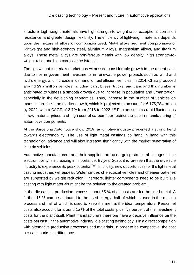
Die casting technology – Present and future in automotive applications
111
structure. Lightweight materials have high strength-to-weight ratio, exceptional corrosion resistance, and greater design flexibility. The efficiency of lightweight materials depends upon the mixture of alloys or composites used. Metal alloys segment compromises of lightweight and high-strength steel, aluminum alloys, magnesium alloys, and titanium alloys. These metal alloys are non-ferrous metals with low density, high strength-to-weight ratio, and high corrosive resistance.
The lightweight materials market has witnessed considerable growth in the recent past, due to rise in government investments in renewable power projects such as wind and hydro energy, and increase in demand for fuel efficient vehicles. In 2014, China produced around 23.7 million vehicles including cars, buses, trucks, and vans and this number is anticipated to witness a smooth growth due to increase in population and urbanization, especially in the developing economies. Thus, increase in the number of vehicles on roads in turn fuels the market growth, which is projected to account for € 175,784 million by 2022, with a CAGR of 3.7% from 2016 to 2022. [59] Factors such as rapid fluctuations in raw material prices and high cost of carbon fiber restrict the use in manufacturing of automotive components.
At the Barcelona Automotive show 2019, automotive industry presented a strong trend towards electromobility. The use of light metal castings go hand in hand with this technological advance and will also increase significantly with the market penetration of electric vehicles.
Automotive manufacturers and their suppliers are undergoing structural changes since electromobility is increasing in importance. By year 2025, it is foreseen that the e-vehicle industry to experience its peak potential [59]. Implicitly, new opportunities for the light metal casting industries will appear. Wider ranges of electrical vehicles and cheaper batteries are supported by weight reduction. Therefore, lighter components need to be built. Die casting with light materials might be the solution to the created problem.
In the die casting production process, about 65 % of all costs are for the used metal. A further 15 % can be attributed to the used energy, half of which is used in the melting process and half of which is used to keep the melt at the ideal temperature. Personnel costs also account for around 15 % of the total costs, plus five percent of the investment costs for the plant itself. Plant manufacturers therefore have a decisive influence on the costs per cast. In the automotive industry, die casting technology is in a direct competition with alternative production processes and materials. In order to be competitive, the cost per cast marks the difference.

Die casting technology – Present and future in automotive applications
112
8.1.1.2 Lightweight construction - the innovation driver
Future cars will demand lighter components as compared to iron and steel ones in order to compensate for the additional weight of the heavy batteries. The factors that contribute to the automotive lightweight construction, are represented by legal requirements, resource conservation, electromobility and improved driving dynamics from the perspective of costs, new technology and their implementation and final customer benefits. The demanding emission regulations and technical requirements of future vehicles are the major drivers for considering new lightweight materials. The energy balance in the future between low-emissions and low energy highly depends on effective lightweight construction. Therefore, the solution is building integrative vehicle concepts that embraces lightweight material concepts, technology and innovation altogether.
It is believed that a multi-material approach would be the solution to environment protection concerns and energy efficiency improvement. Cost-effective solutions also lead to combining different materials approach by considering the stability requirements and other specifications. It is also expected that hybrid-lightweight construction and composite construction methods will continue to gain in importance.
8.1.2 Economic effectiveness
One of the most important consumer driven factors in automotive industry is the cost that determines whether any new material has an opportunity to be selected for a vehicle component.
Cost includes three components:
- actual cost of raw materials - manufacturing value added - cost for product designing and testing
Aluminum and magnesium alloys are certainly more expensive than the currently used steel and cast irons. Since cost may be higher, decisions to select light metals must be justified on the basis of improved functionality. Meanwhile the high cost is one of the major obstacles in use of the composite materials.

Die casting technology – Present and future in automotive applications
113
8.1.3 Safety
The ability to absorb impact energy and be survivable for the passengers is called “crashworthiness” of the structure in vehicle. At first two concepts in automotive industry should be considered: crashworthiness and penetration resistance. In the more accurate definition of crashworthiness, it is the potential of absorption of energy through controlled failure modes and mechanisms. However, penetration resistance is concerned with the total absorption without allowing projectile or fragment penetration.
8.1.4 Recycling
Most important concerns in industries such as automotive, are ‘protection of resources’, ‘reduction of CO2 emissions’, and ‘recycling’. There are some guidelines in European Union and Asian countries about this issue. While the United States has not issued any regulations concerning automotive end-of-life requirements. [60]
For example, in the UK, around two million vehicles reach the end of their life each year and these vehicles are considered as hazardous waste until they have been fully treated.
8.2 New materials for automotive industry
8.2.1 Aluminum
There is a wide variety of aluminum usage in automotive powertrain, chassis and body structure. Use of aluminum can potentially reduce the weight of the vehicle body. Its low density and high specific energy absorption performance and good specific strength are its most important properties.
Aluminum is also resistance to corrosion. But according to its low modulus of elasticity, it cannot substitute steel parts and therefore those parts need to be re-engineered to achieve the same mechanical strength, but still aluminum offers weight reduction.
Aluminum usage in automotive industry has grown within past years. In automotive powertrain, aluminum castings have been used for almost 100% of pistons, about 75% of cylinder heads, 85% of intake manifolds and transmission. For chassis applications, aluminum castings are used for about 40% of wheels, and for brackets, brake components, suspension, steering components and nutriment panels. Aluminum is used for body structures, closures and exterior attachments such as crossbeams, doors or bonnets.

Die casting technology – Present and future in automotive applications
114
Recent developments have shown that up to 50% weight saving for the body in white (BIW) can be achieved by the substitution of steel by aluminum. This can result in a 20- 30% total vehicle weight reduction. [64]
The cost of aluminum and price stability is its biggest obstacle for its application.
Aluminum is becoming popular material slowly owing to its ability to be easily recycled. About 70% of aluminum consumed can be reused. Increased automation in the die casting industry has penetrated productivity. This has raised the demand for eminently durable die casting parts from the automotive industry.
North America is the leading market for automotive aluminum die casting worldwide. More than 90% of the aluminum die-casting produced in the United States is made from post- consumer recycled aluminum. [61]
Rising esteem for fuel-efficient vehicles and a need to reduce the vehicle weight significantly influenced the aluminum die casting parts in the UK automotive industry.
Automotive industry grew significantly over the last decades. Shrewd die-casting companies took advantage of the aluminum boom and expanded alongside it, benefitting from the vast die casting market.
Aluminum production is in a continuous growth due to the increasing number of products from automotive and aerospace industry, mechanical engineering sector and packaging industries that can be produced through die casting technology. World aluminum production grew by 6% only in 2017. [61]
In the past, Aluminum was one of the most valuable substances in the world. Nowadays, it is the second most popular metal (after steel). Studies show that global consumption of Aluminum is expected to significantly rise to 120 million tones by the year 2025 [61]. This high demand will have a great influence on the world´s foundries. The main drivers to the constantly growing aluminum production are represented by the environmental legislation pressure to reduce CO2 emission by reducing fuel consumption. The idea of green vehicles, environment friendly lead to light vehicles. This is possible by replacing the heavy steel in the components with featherweight aluminum. It is foreseen that by 2022, most of the heavier components to be built of aluminum; the average car will be contain approximately 100 extra kilograms of aluminum [61], which will lead to a lighter vehicle and a significant reduction in fuel consumption. By 2025, it is expected to double the global consumption of aluminum in vehicle construction from 12% to around 25% (30 million tons). Foundries already notice that aluminum and other light metals take a more prominent part in their casting markets. [61]
Other casting producing regions, such as India, are also pivoting towards aluminum. In Europe, the situation is similar. Aluminum use is increasing a lot because of the changes

Die casting technology – Present and future in automotive applications
115
that automotive manufacturing sector is suffering. The rapid shift to aluminum from steel and other metals marks a great opportunity for foundries.
Electrical vehicles boost new components suitable for die casting technology. The switch of the automotive industry towards complete electric cars will have a major impact on aluminum foundries as suppliers.
The penetration of BEVs will increase rapidly. Looking at the latest projections from 24 different automotive forecasting institutes and tier suppliers a worldwide BEV penetration of 6,86% (range between 2% - 15%) is expected by 2025 growing to 18,56% (range between 5,75% - 34%) in 2030.
Figure 54. Development of demand for aluminum castings in the automotive industry over the next
decade [62]

Die casting technology – Present and future in automotive applications
116
Figure 55. The forecasts for pure electric vehicles depending on the policy of different countries. [62]
Figure 56. Cast aluminum frame applications contribute to the growing market [62]
Though aluminum is dominating the current market, it is expected that magnesium will be gaining a significant market share.

Die casting technology – Present and future in automotive applications
117
8.2.2 Magnesium as a lightweight material
In the car industry, manufacturers focus on lightweight materials such as aluminum or carbon fiber. Their advantage stands in the fact that there are affordable and common. Automotive industry is aiming to also establish magnesium as a lightweight material. It is becoming increasingly common in automotive engineering.
In terms of weight, Magnesium is 33% lighter than Aluminum and 73% lighter than steel or Zinc. Magnesium is used in manufacturing not only for the weight reason. Between its properties can be listed its dumping capacity, it can be used in driving wheels, engine cases, has a good application for electronic cases, presents good heat dissipation, wear resistance, good resistance at impact, dimensional stability and it is not magnetic. Magnesium alloys have distinct advantages over aluminum that include better manufacturability, longer die life and faster solidification. Magnesium components have higher machinability.
Low weight. Density (gr / cc)
Mg AI Zn
1.8 2.7 6.7
Table 11. Density comparison among materials produced in Zatorcal
Magnesium components have many physical property disadvantages that require unique design for application to automotive products. Although its tensile yield strength is about the same, magnesium has lower ultimate tensile strength fatigue strength, and creep strength compared to aluminum. The modulus and hardness of magnesium alloys is lower than aluminum and the thermal expansion coefficient is greater.
Because of its too low mechanical strength, pure magnesium must be alloyed with other elements. The most common alloying elements is Mg-Al-Zn group that contains aluminum, manganese, and zinc.
Increased efficiency through weight reduction and cost optimization due to a larger shot guarantee in the die casting tool are the main reasons OEMs choose Magnesium for components.

Die casting technology – Present and future in automotive applications
118
Tooling guarantee (shots)
Mg AI Zn
500.000 150.000 – 250.000 400.000
Table 12. Tooling guarantee depending on the used material for injection
Due to the increasing preoccupation for the finite natural resources, specialists are looking for material substitutions. The strategy is to adapt processes in order to reduce the input as much as possible and still be able to have a great output. In other words, companies need to adapt their manufacturing strategies so that they can get as much done with the least possible resources and still be able to keep the economic benefit. This is the case of the materials used in industries. From the perspective of components material, there are some key characteristics that the materials of the future need to meet. They need to be economical (so that the business is still profitable), to be durable (to meet quality and safety standards) to be lightweight (to save as much energy as possible), but at the same time they need to be stiffen so that in case of an impact to be able to absorb as much energy as possible.
The higher price per kilo of magnesium compared to aluminum discourages many companies. Due to the lower density, however, the volume price is almost identical. Magnesium is the lightest technical metallic construction material. It is more heat-resistant than plastic and provides a high shielding capacity against electromagnetic interference. Due to the high elasticity of magnesium, vibrations can be absorbed even with large and thin-walled parts. Magnesium components require surface protection and can be painted or powder-coated in various processes. The light metal also offers a major advantage in terms of availability: even seawater contains 1 kg of magnesium per cubic meter. Further advantages are a high-quality metallic appearance and perfect recyclability.
Capability to form casting with EMI and RFI shielding, complete recyclability, more electrical conductivity are some of the factors propelling the growth of magnesium market.
China produces more than 50% of the global magnesium metal [62]. Magnesium being cheap in China collapsed the main supply base of the western world.
Automotive industry is continuously analyzing the consumption of lightweight materials in automotive applications. Lightweight materials like aluminum, magnesium and carbon

Die casting technology – Present and future in automotive applications
119
fiber are currently in high demand as low weight equals longer range or a reduction of the battery cost for an electric vehicle.
8.2.3 Advanced composite materials
Fiber reinforced composites offer a wide range of advantages to the automotive industry. It has the potential for saving weight offered by their low density. Component designs can be such that the fibers lie in the direction of the principal stresses, and amount of fiber used is sufficient to withstand the stress, thus optimizing materials usage. [63]
8.2.4 Glass-fiber composites
Glass fiber is being used mostly for the sports car which includes Formula 1 cars. It is lighter than steel and aluminum, easy to be shaped and rust-proof. And more important factor is that it is cheap to be produced in small quantity. [63]
8.2.5 Graphene
Graphene in its purest form is a single sheet of carbon arranged hexagonally on the atomic level. A semi-metal, and currently the strongest and thinnest material known to science, graphene is being shortlisted as a potential replacement for silicon as an essential component of computer chips.
Graphene is also being explored for use in touchscreen displays and filtration technology. First discovered in 2004, controlled-manufactured graphene has only become a reality in the last ten years, meaning commercial graphene sheets have only recently stopped being cost-prohibitive. The increasing affordability of graphene is due to the chemical vapor deposition method of creating the material as well as other refinements of the process. [63]
8.2.6 Aerogel
Technically an entire class of different types, aerogel is an ultralight material, with 95-99% of it consisting of air or other gas. Although it may appear to be foam or a type of translucent sponge, the insulating nature of aerogels make them capable of protecting against extremely high temperatures.
This makes aerogels an attractive material for heat insulation as well as other uses which require shielding from against high temperatures. [64]
8.2.7 Transparent aluminum
Transparent aluminum is a clear material three-times stronger than steel. While being able to use transparent aluminum to build ultrathin windows capable of withstanding

Die casting technology – Present and future in automotive applications
120
direct bullet impacts, it is being considered as a huge breakthrough, as a result of the perseverance of science. [64]
8.2.8 Carbon-fiber epoxy composite
Most recently, the most of the racing car companies much more rely on composites form whether it would be plastic composites, Kevlar and most importantly carbon-fiber epoxy composition. It is because the composite structures are the high strength/low weight ratio. The most common materials used for racing cars are carbon (graphite), Kevlar and glass fibers. Epoxy composites have been the first choice in Formula 1 car industries and other race cars. [63]
8.2.9 Carbon fiber
Carbon fibers are fibers about 5–10 micrometers in diameter and composed mostly of carbon atoms. Carbon fibers have several advantages including high stiffness, high tensile strength, low weight, high chemical resistance, high temperature tolerance and low thermal expansion. These properties have made carbon fiber very popular in aerospace, civil engineering, military, and motorsports, along with other competition sports. However, they are relatively expensive when compared with similar fibers, such as glass fibers or plastic fibers. [63]
To produce a carbon fiber, the carbon atoms are bonded together in crystals that are more or less aligned parallel to the long axis of the fiber as the crystal alignment gives the fiber high strength-to-volume ratio (making it strong for its size). Several thousand carbon fibers are bundled together to form a tow, which may be used by itself or woven into a fabric.
Carbon fibers are usually combined with other materials to form a composite. When impregnated with a plastic resin and baked it forms carbon-fiber-reinforced polymer (often referred to as carbon fiber) which has a very high strength-to-weight ratio, and is extremely rigid although somewhat brittle. Carbon fibers are also composited with other materials, such as graphite, to form reinforced carbon-carbon composites, which have a very high heat tolerance.
Carbon fibers were developed in the 1950s as a reinforcement for high-temperature molded plastic components on missiles. The first fibers were manufactured by heating strands of rayon until they carbonized. This process proved to be inefficient, as the resulting fibers contained only about 20% carbon and had low strength and stiffness properties. [65]
In the manufacturing process, the raw materials, which are called precursors, are drawn into long strands or fibers. The fibers are woven into fabric or combined with other

Die casting technology – Present and future in automotive applications
121
materials that are filament wound or molded into desired shapes and sizes. There are typically five segments in the manufacturing of carbon fibers from the PAN process. These are:
o Spinning. PAN mixed with other ingredients and spun into fibers, which are washed and stretched.
o Stabilizing. Chemical alteration to stabilize bonding. o Carbonizing. Stabilized fibers heated to very high temperature forming tightly
bonded carbon crystals. o Treating the Surface of fibers (fibers are oxidized to improve bonding properties). o Sizing. Fibers are coated and wound onto roll, which are loaded onto spinning
machines that twist the fibers into different size yarns. To form composite materials, heat, pressure, or a vacuum binds fibers together with a plastic polymer.
When the carbon is manufactured into fibers, special additives and elements are introduced to increase strength properties. Carbon is manufactured into tiny fibers through either the PAN or Pitch process. The carbon is manufactured in bundles of thousands of tiny filaments, and wound onto a roll. There are three major categories of raw carbon fiber:
o High Modulus Carbon Fiber (Aerospace Grade) o Intermediate Modulus Carbon Fiber o Standard Modulus Carbon Fiber (Commercial Grade)
When compared to steel, carbon fiber is actually 5 times stronger than steel. It is also 2 times more stiffness. This material has a really very strength-to weight ratio, which makes it great for almost anything that requires high strength and low weight. It is also highly chemically resistant and have high temperature tolerance with low thermal expansion.
Manufacturing carbon fibers carries a number of challenges, such as:
o the need for more cost-effective recovery and repair o close control required to ensure consistent quality o health and safety issues o skin irritation o breathing irritation
Among its advantages, can be listed the following:
o it has the greatest compressive strength of all reinforcing materials o long service life o low coefficient of thermal expansion o its density is much lower than the density of steel o exhibit properties better than any other metal

Die casting technology – Present and future in automotive applications
122
o insensitive to temperature changes
Among its disadvantages can be listed:
o high cost o can cause some forms of lung cancer
Applications of carbon fiber:
o portable power o rechargeable batteries and fuel cell electrodes o fiber reinforced plastics, FRP o energy production, windmill blades, wind turbines o building and construction materials o aerospace and aircraft industry o sports equipment o automotive parts o compressed natural gas storage and transportation fuel cells o infrastructure, earthquake protection
The future efforts on carbon fiber research will be focused on cost reduction and property improvement. The mechanical property of carbon fiber heavily relies on its microstructure. The improvement on the tensile, flexural, and shear strength of pitch carbon fibers has been observed by randomizing the graphite distribution in the fiber transverse direction.
The progress and developments in materials technology have resulted in several new materials like metal–matrix composites (MMCs). On account of excellent physical, mechanical and development properties, MMCs are applied widely in aircraft and automobile technology. The present paper deals with the development of aluminum matrix composite reinforced with carbon preform having a volume fraction of 20–25% using squeeze casting infiltration process. Hardness, impact and tension test on the squeeze cast matrix and the composite was conducted to study the improvement in properties compare to that of matrix. Even though ultimate tensile strength of composite is found to be decreased, an increased Brinell hardness number and a four-fold improvement in toughness are noticed. Characterization of the materials done using optical and scanning electron microscope (SEM) revealed that the carbon fibers are evenly distributed in the matrix and the alloy is appeared to have smaller dendrite size. The lack of observed fiber pull-out on fracture and improved mechanical properties resulted due to the good wetting of the fibers by the liquid alloy. [65]
This produces strong matrix-interface bonding and yields an efficient load transfer from the softer aluminum matrix to the much stronger carbon fibers. Therefore, in agreement with the rule of mixture, the addition of carbon fiber initially increases the aluminum

Die casting technology – Present and future in automotive applications
123
composite hardness substantially, which also attests for the preserved load bearing capacity of the fibers and supports the absence of considerable carbon fiber damage
Carbon fiber reinforced metal matrix composites developed in the last few decades are leading to remarkable improvements in industries, due to its excellent mechanical and chemical properties and high cost performance. Aerospace, automotive and other industries are always striving to find newer and better reinforcing materials to manufacture new or improved products for new applications.
Carbon fibers are used as one of the reinforcements for aluminum alloys because they increase their stiffness and strength. Carbon fibers has been widely used as reinforcements in composites such as carbon fiber reinforced metals, plastics and ceramics due to their high specific strength, high electric and thermal conductivity, good self-lubrication and low expansion coefficient. Also, carbon fibers increase the wear resistance and also reduce the friction coefficient of AMCs.
8.3 Effects of electromobility on materials
Due to the constant preoccupation for footprint, pollution and restrictions of the conventional combustion engines vehicles in urban agglomerations, the acceptance and implementation of electro mobility is an actual thing.
"Electrical power is not the only option, there are also good combinations — at least until we have made substantial progress in developing adequate solutions for energy storage, i.e. the energy that is available in the vehicle," explained Schek. “Electric cars and plug-in hybrids have already been on the streets for some while. [71]
Schek illustrated the benefits of lightweight construction for electromobility in an example. “If I reduce the mass of the vehicle equipped with an internal combustion engine and one with an electric drive by ten percent each. What benefits do I achieve? Acceleration values give us a good idea: If the vehicles have approximately the same specific power, electric vehicles often contribute more power to acceleration because of the advantage they gain by the weight reduction. This is because nowadays most vehicles with internal combustion engines continuously provide optimum tractive power thanks to modern transmission technology. The full torque of the electric vehicle is available almost from the start, but the vehicles are usually designed for one or two gears. Therefore, the maximum tractive force is not available in every situation. Additionally, the following principle applies: The greater the ratio of kilowatt to kilogram, the lower is the impact of
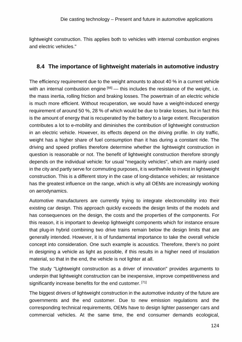
Die casting technology – Present and future in automotive applications
124
lightweight construction. This applies both to vehicles with internal combustion engines and electric vehicles."
8.4 The importance of lightweight materials in automotive industry
The efficiency requirement due to the weight amounts to about 40 % in a current vehicle with an internal combustion engine [66] — this includes the resistance of the weight, i.e. the mass inertia, rolling friction and braking losses. The powertrain of an electric vehicle is much more efficient. Without recuperation, we would have a weight-induced energy requirement of around 50 %, 28 % of which would be due to brake losses, but in fact this is the amount of energy that is recuperated by the battery to a large extent. Recuperation contributes a lot to e-mobility and diminishes the contribution of lightweight construction in an electric vehicle. However, its effects depend on the driving profile. In city traffic, weight has a higher share of fuel consumption than it has during a constant ride. The driving and speed profiles therefore determine whether the lightweight construction in question is reasonable or not. The benefit of lightweight construction therefore strongly depends on the individual vehicle: for usual "megacity vehicles", which are mainly used in the city and partly serve for commuting purposes, it is worthwhile to invest in lightweight construction. This is a different story in the case of long-distance vehicles; air resistance has the greatest influence on the range, which is why all OEMs are increasingly working on aerodynamics.
Automotive manufacturers are currently trying to integrate electromobility into their existing car design. This approach quickly exceeds the design limits of the models and has consequences on the design, the costs and the properties of the components. For this reason, it is important to develop lightweight components which for instance ensure that plug-in hybrid combining two drive trains remain below the design limits that are generally intended. However, it is of fundamental importance to take the overall vehicle concept into consideration. One such example is acoustics. Therefore, there's no point in designing a vehicle as light as possible, if this results in a higher need of insulation material, so that in the end, the vehicle is not lighter at all.
The study "Lightweight construction as a driver of innovation" provides arguments to underpin that lightweight construction can be inexpensive, improve competitiveness and significantly increase benefits for the end customer. [71]
The biggest drivers of lightweight construction in the automotive industry of the future are governments and the end customer. Due to new emission regulations and the corresponding technical requirements, OEMs have to design lighter passenger cars and commercial vehicles. At the same time, the end consumer demands ecological,

Die casting technology – Present and future in automotive applications
125
economical and sustainable vehicles. From a technological point of view, lightweight construction plays a central role in this area of tension, since it reduces the mass of a vehicle and therefore fuel consumption and emission values. At the same time lightweight construction can increase driving dynamics.
The study "Lightweight construction as an innovation driver" provides arguments for the industry to underpin that lightweight construction: it can be inexpensive, improve the competitiveness of local companies, for example compared to (new) international competitors, it significantly increases end customer benefits and is considered a major driver of innovation.
Many companies see a significant success factor for lightweight construction in the integration of lightweight material as well as functional and manufacturing processes of lightweight construction. However, holistic, systemic lightweight construction must take all modules of a vehicle into consideration. Seam joints, which previously hindered transfer to adjacent vehicle areas, have to be gradually reduced. The experts still see the greatest potential for lightweight construction in the body, powertrain and chassis. It is important to involve suppliers in the development of components, assemblies and modules as early as possible. In principle, suppliers are well advised to strengthen their own development competencies in order to be able to understand, control and implement the full scope. Furthermore, new lightweight construction approaches should have already been successfully applied in other industries, such as sports goods, aviation and/or construction.
Developers used to think more about the material, but today they are tackling lightweight construction in an integrative manner. This hybrid lightweight design is a further trend. For example, composites absorb tensile forces very well, while metallic materials are more in demand for compressive forces."
Many components will suffer significant changes in material within the next 10 years. Lightweight materials will be the key factor when leading competence among OEMs. The integration of lightweight material use in the design of car components can highly influence the brand and the overall business of premium OEMs.
Key materials that are expected to play an increasingly important role in the future are high-strength steels, aluminum, plastics, sandwich materials (various combinations of these three), magnesium, and to some extent carbon fiber. Structural parts (e.g., frame or seat structure) will often consist of high-strength steel or aluminum or even carbon fiber. Functional parts, where strength is the key requirement such as transmission or steering, will be built out of high-strength steel or carbon fiber. The predominant element for interiors today will remain plastic and will become even more important, when it comes

Die casting technology – Present and future in automotive applications
126
to substitute windshields/screens and nonstructural body parts, due to its cost-weight ratio.
According to experts, the production of lightweight design elements will increase by 400 % during the next eight years. In general, a reduction of vehicle mass of 100 kg reduces fuel consumption of about 0.2 to 0.3 liters per 100 km.
A look at the automotive industry shows that seven years ago only 6 kg of magnesium was used per vehicle. Experts expect up to 100 kg of magnesium per body by 2020.
The materials of tomorrow are expected to require low quantities of energy in order to operate. The influence in costs is highlighted from one scenario to the other, depending on the percentages of materials used. Materials that require a higher quantity of energy to be produced, such as high strength steel (HSS), will impact the results depending on its usage.
The study below represents the influence of lightweight materials in the construction of a vehicle. The first scenario highlights the weight reduction results by replacing steel with high strength steel.
The overall weight reduction through using lighter materials leads to an increased saving in costs per kilogram due to the usage of materials that are cheaper to manufacture.
Table 13. Weight and cost impact in conventional lightweight scenario
The second scenario represents a moderate lightweight usage of materials. Magnesium and carbon fiber are introduced and their influence is easy to spot in the higher reduction of weight. There is no huge impact on the cost/kilogram due to the increased percentage of aluminum and magnesium.
Aluminum8%
Plastics9%
Steel15%
HSS48%
Other20%
CONVENTIONAL LIGHTWEIGHT
Replacement of steel with high strength steelReduction of: 250 kg (18%)
Price: €3,00/kg saved

Die casting technology – Present and future in automotive applications
127
Table 14. Weight and cost impact in moderate lightweight scenario
Carbon fiber1%
Magnesium16%
Aluminum23%
Plastics20%
Steel7%
HSS14%
Other19%
MODERATE LIGHTWEIGHT
Usage of light metals and sandwich structuresReduction of: 420 kg (30%)
Price: €4,00/kg saved

Die casting technology – Present and future in automotive applications
128
The third scenario is applied to an extreme lightweight design. A drastic reduction in weight can be spotted due to an increased usage of carbon fiber. The saving in costs is doubled due to the fact that aluminum, magnesium and most of all high strength steel percentages are reduced. Thus, this scenario states as the best example that lightweight construction in strongly related to cost benefits.
Table 15. Weight and cost impact in extreme lightweight scenario
Die casting foundries are usually a symbol of mass production, especially in the automotive industry. However, medium-sized companies can also occupy a niche with light metal processing and succeed in a highly competitive market. Zatorcal positioned itself as a specialist for small and medium-sized series. With less automation, but all the more flexibility from experienced employees. Many global corporations therefore have their aluminum, magnesium or zinc components manufactured by the small and medium-sized enterprise in Spain.
Carbon fiber36%
Magnesium7%
Aluminum3% Plastics
15%Steel8%
HSS8%
Other23%
EXTREME LIGHTWEIGHT
Extensive usage of carbon fiber materials for maximum weight savingsReduction of: 490 kg (35%)
Price: €9,00/kg saved

Die casting technology – Present and future in automotive applications
129
9 Conclusion and outlook
The rising speed of technological progress makes foundries face new situations. New technology adoption at an early stage might be the key to surviving in such a competitive and demanding environment.
Leaders in vehicle manufacturing use hybrid steel/aluminum or steel/magnesium structures for their car components. The usage of these materials can achieve considerable weight savings and thus lower fuel consumption.
Autonomous vehicles and electric cars create the necessity of new design, new materials and new technology that can efficiently and responsively use resources and create components that meet the requirements of the automobile industry.
Only flexible foundries, prepared for the change, opened to adopting innovation and embrace new technologies will benefit from the raising market of changing product portfolios. In the medium term, competitive costs can only be achieved through productivity improvements. Investment in technology is of existential importance. Apart from the cost-efficiency manufacturing, it also improves the development competence, components quality and production capacities.
Modern manufacturing systems guarantee working in an energy and material-efficient manner and can be flexibly adapted to new market and order situations. By using these systems, die casting foundries can use considerable saving potentials and thus strengthen their competitiveness. Therefore, constant and meaningful investments are necessary to keep the production facility up to date. Lasting cooperation with suppliers and customers also helps to make the necessary investments and to develop solutions which offer added value to the customers.
And last but not least, it is the ability to recognize market and customer needs early on and to provide solutions as well as to ensure a comprehensive, customer-focused service which help die casting foundries to exist in a global market.

Die casting technology – Present and future in automotive applications
130
References
[1] «Zatorcal,» [En línea]. Available: www.zatorcal.com. [Último acceso: 07 03 2019].
[2] «MArketers Media,» [En línea]. Available: https://marketersmedia.com/automotive-parts-die-casting-market-2017-global-analysis-opportunities-and-forecast-to-2022/160483. [Último acceso: 09 05 2019].
[3] «Wikipedia,» [En línea]. Available: https://en.wikipedia.org/wiki/Die_casting. [Último acceso: 10 05 2019].
[4] «CWM die cast,» [En línea]. Available: https://www.cwmdiecast.com/blog/2016/05/24/die-casting-101-hot-chamber-vs-cold-chamber/. [Último acceso: 11 05 2019].
[5] «North America die casting association - NADCA,» [En línea]. Available: https://www.diecastingdesign.org/. [Último acceso: O6 06 2019].
[6] «Engineering notes,» [En línea]. Available: http://www.engineeringenotes.com/metallurgy/casting/die-casting-alloys-used-in-industries-5-types-metallurgy/21052. [Último acceso: 06 06 2019].
[7] CRC Handbook of Chemistry and Physics, 1996.
[8] «Procast - Quikcast,» [En línea]. Available: https://www.esi-group.com/es/soluciones-de-software/procesos-y-fabricacion/fundicion/procast-quikcast. [Último acceso: 06 06 2019].
[9] «Freudenberg,» [En línea]. Available: https://www.fcs-muenchen.com/news/2015/druckgiess-prozesse-mit-der-waermebildkamera-ueberwachen-278. [Último acceso: 06 06 2019].
[10] «Techpats,» [En línea]. Available: https://www.techpats.com/3d-printing-technologies-overview/. [Último acceso: 05 05 2019].
[11] «Wikipedia,» [En línea]. Available: https://en.wikipedia.org/wiki/Stereolithography. [Último acceso: 07 06 2019].

Die casting technology – Present and future in automotive applications
131
[12] «Wikipedia,» [En línea]. Available: https://en.wikipedia.org/wiki/Fused_deposition_modeling. [Último acceso: 07 06 2019].
[13] «Britannica,» [En línea]. Available: https://www.britannica.com/technology/selective-laser-sintering. [Último acceso: 07 06 2019].
[14] «Live science,» [En línea]. Available: http://www.livescience.com/40310-laminated-object-manufacturing.html. [Último acceso: 07 06 2019].
[15] «Markforged,» [En línea]. Available: https://markforged.com/. [Último acceso: 06 06 2019].
[16] «Britannica,» [En línea]. Available: https://www.britannica.com/technology/nanotechnology. [Último acceso: 07 06 2019].
[17] T. Tsuzuki, «International Journal of Nanotechnology (IJNT), Vol. 6, No. 5/6, 2009,» 5 6 2009. [En línea]. [Último acceso: 07 06 2019].
[18] «NADCA,» [En línea]. Available: https://www.sfsa.org/tutorials/nadca2/TFAN13.htm. [Último acceso: 06 06 2019].
[19] «Premier die casting,» [En línea]. Available: https://diecasting.com/blog/2016/04/19/the-difference-between-aluminum-magnesium-and-zinc-alloys/. [Último acceso: 12 05 2019].
[20] «Thomasnet,» [En línea]. Available: https://www.thomasnet.com/articles/custom-manufacturing-fabricating/casting-materials. [Último acceso: 07 06 2019].
[21] «Dynacast,» [En línea]. Available: https://www.dynacast.com/die-cast-metal-properties. [Último acceso: 07 06 2019].
[22] «substech,» [En línea]. Available: http://www.substech.com/dokuwiki/doku.php?id=classification_of_aluminum_alloys. [Último acceso: 07 06 2019].

Die casting technology – Present and future in automotive applications
132
[23] «Catalogue of european standards in the aluminum and aluminum alloys field,» [En línea]. Available: https://european-aluminium.eu/media/2318/catalogue-cen-tc-132-september-2018.pdf. [Último acceso: 12 05 2019].
[24] «Substech,» [En línea]. Available: http://www.substech.com/dokuwiki/doku.php?id=cast_magnesium_alloys. [Último acceso: 12 05 2019].
[25] «Die casting,» 19 04 2016. [En línea]. Available: https://diecasting.com/blog/2016/04/19/the-difference-between-aluminum-magnesium-and-zinc-alloys/. [Último acceso: 02 05 2019].
[26] «Kirchoff automotive,» [En línea]. Available: https://www.kirchhoff-automotive.com/es/productos/. [Último acceso: 19 04 2019].
[27] «The telegraph,» [En línea]. Available: https://www.telegraph.co.uk/motoring/car-manufacturers/porsche/8467153/Lohner-Semper-Vivus-review.html. [Último acceso: 03 03 2019].
[28] «Newsroom Toyota,» [En línea]. Available: https://newsroom.toyota.eu. [Último acceso: 17 04 2019].
[29] «US Department of Energy,» [En línea]. Available: www.fueleconomy.gov. [Último acceso: 06 06 2019].
[30] «Plugin America,» [En línea]. Available: https://pluginamerica.org/how-much-does-it-cost-charge-electric-car/. [Último acceso: 02 06 2019].
[31] «Wikipedia,» [En línea]. Available: https://en.wikipedia.org/wiki/List_of_electric_cars_currently_available. [Último acceso: 03 06 2019].
[32] «Spotlightmetal,» [En línea]. Available: https://www.spotlightmetal.com/electromobility-definition-vehicles-and-future-a-810482/. [Último acceso: 12 04 2019].
[33] «Spotlightmetal,» [En línea]. Available: https://www.spotlightmetal.com/electromobility-definition-vehicles-and-future-a-810482/. [Último acceso: 12 03 2019].

Die casting technology – Present and future in automotive applications
133
[34] «Renault,» [En línea]. Available: https://group.renault.com/actualites/blog-renault/mondial2016-nouvelle-autonomie-record-pour-renault-zoe/. [Último acceso: 11 02 2019].
[35] «Innogy,» [En línea]. Available: https://www.innogy-emobility.com/unternehmen. [Último acceso: 11 02 2019].
[36] «st,» [En línea]. Available: https://www.st.com/en/applications/adas.html. [Último acceso: 07 06 2019].
[37] «University of Michigan,» [En línea]. Available: https://mcity.umich.edu/wp-content/uploads/2017/05/Mcity-White-Paper_Accelerated-AV-Testing.pdf. [Último acceso: 05 05 2019].
[38] «interesting engineering,» [En línea]. Available: https://interestingengineering.com/cheap-cameras-might-be-just-as-good-as-lidar-new-study-shows. [Último acceso: 07 03 2019].
[39] «Interesting engineering,» [En línea]. Available: https://interestingengineering.com/the-6-levels-of-autonomous-driving-and-the-future-of-autonomous-cars-in-china. [Último acceso: 11 05 2019].
[40] «Science direct,» [En línea]. Available: https://www.sciencedirect.com/topics/computer-science/artificial-intelligence. [Último acceso: 13 03 2019].
[41] «Yubanet,» [En línea]. Available: https://yubanet.com/world/of-the-1-3-million-people-dying-each-year-from-traffic-accidents-49-per-cent-are-pedestrians-cyclists-and-motorcyclists/. [Último acceso: 05 05 2019].
[42] [En línea]. Available: https://news.ihsmarkit.com/press-release/automotive/autonomous-vehicle-sales-set-reach-21-million-globally-2035-ihs-says. [Último acceso: 05 05 2019].
[43] Center of Automotive Management (CAM) from Bergisch Gladbach , «Market Development of Electric Vehicles for the Year 2030: Germany, EU, USA and China».

Die casting technology – Present and future in automotive applications
134
[44] [En línea]. Available: https://news.ihsmarkit.com/press-release/automotive/autonomous-vehicle-sales-set-reach-21-million-globally-2035-ihs-says.
[45] «Spotlightmetal,» [En línea]. Available: https://www.spotlightmetal.com/die-casting-foundries-undergo-radical-change-a-789563/. [Último acceso: 12 03 2019].
[46] «Vogel,» [En línea]. Available: https://www.etmm-online.com/electromobility-has-no-viable-future-without-foundries-a-700510/. [Último acceso: 20 05 2019].
[47] «Schaeffler,» [En línea]. Available: https://www.schaeffler.es/content.schaeffler.es/es/index.jsp. [Último acceso: 12 03 2019].
[48] V. Kanat, «Linkedin,» [En línea]. Available: https://www.linkedin.com/pulse/e-mobility-electrified-steel-castings-victoria-kanat. [Último acceso: 17 05 2019].
[49] «foundry-planet,» [En línea]. Available: https://www.foundry-planet.com/equipment/detail-view/e-mobility-electrified-with-steel-and-castings/?cHash=7953bf52f969ffe00fec91bd479b923f. [Último acceso: 01 06 2019].
[50] «Audi,» [En línea]. Available: https://www.audi.com/en/experience-audi/models-and-technology/alternative-drive-systems.html. [Último acceso: 02 03 2019].
[51] «spotlightmetal,» [En línea]. Available: https://www.spotlightmetal.com/development-of-electric-mobility-until-2030-a-694090/. [Último acceso: 15 05 2019].
[52] «Spotlightmetal 2030,» [En línea]. Available: https://www.spotlightmetal.com/development-of-electric-mobility-until-2030-a-694090/. [Último acceso: 02 05 2019].
[53] «metal working world magazine,» Fabio Boiocchi, 11 12 2018. [En línea]. Available: https://www.metalworkingworldmagazine.com/challenges-in-the-market-for-structural-castings-posed-by-globalization/. [Último acceso: 12 05 2019].

Die casting technology – Present and future in automotive applications
135
[54] «Statistics,» Kraftfahrt-Bundesamt, 2017. [En línea]. Available: https://www.kba.de/EN/Statistik_en/statistik_node_en.html. [Último acceso: 12 05 2019].
[55] «Digital trends,» [En línea]. Available: https://www.digitaltrends.com/cars/cameras-could-soon-replace-mirrors-in-cars/. [Último acceso: 16 02 2019].
[56] «Nikkei,» [En línea]. Available: https://asia.nikkei.com/Business/Companies/Toyota-to-replace-side-view-mirrors-with-cameras-in-new-model. [Último acceso: 03 05 2019].
[57] D. Cross, Optimization of Hybrid Kinetic Energy Recovery Systems (KERS) for Different Racing Circuits SAE Digital Library., SAE International, 25 Sep 2009.
[58] «Magneti Marelli,» [En línea]. Available: https://www.magnetimarelli.com/excellence/technological-excellences. [Último acceso: 09 05 2019].
[59] «gisgeography,» [En línea]. Available: https://gisgeography.com/lidar-light-detection-and-ranging/. [Último acceso: 02 03 2019].
[60] «the library of manufacturing,» [En línea]. Available: http://www.thelibraryofmanufacturing.com/index.html. [Último acceso: 02 02 2019].
[61] «Engineering,» [En línea]. Available: https://www.engineering.com/3DPrinting/3DPrintingArticles/ArticleID/10484/A-Profile-of-Hybrid-Additive-Manufacturing-Technology.aspx. [Último acceso: 17 03 2019].
[62] «Spotlightmetal,» [En línea]. Available: https://www.spotlightmetal.com/3d-printing-voxeljet-accelerates-all-kinds-of-casting-processes-a-767436/. [Último acceso: 07 05 2019].
[63] 24 05 2016. [En línea]. Available: https://blog.adafruit.com/2016/05/24/potting-injection-molding-and-macromelt-electronic-housing-options-explained-by-mindtribe/. [Último acceso: 07 03 2019].

Die casting technology – Present and future in automotive applications
136
[64] «lightweight Spotlightmetal,» [En línea]. Available: https://www.spotlightmetal.com/lightweight-construction-for-tomorrows-mobility-a-683508/. [Último acceso: 05 03 2019].
[65] «Linkedin recycling,» [En línea]. Available: https://www.linkedin.com/pulse/materials-automotive-body-chassis-structure-pooyan-nayyeri?articleId=5982926286694158336. [Último acceso: 07 05 2019].
[66] «envision intelligence market,» [En línea]. Available: https://www.envisioninteligence.com/industry-report/north-america-automotive-parts-magnesium-die-casting-market/. [Último acceso: 03 06 2019].
[67] «AluMag,» [En línea]. Available: https://alumag.com/alumag-in-the-news/increasing-penetration-of-bevs-overcapacity-of-or-opportunity-for-cast-aluminium/. [Último acceso: 03 03 2019].
[68] «Linkedin automotive materials,» [En línea]. Available: https://www.linkedin.com/pulse/materials-automotive-body-chassis-structure-pooyan-nayyeri. [Último acceso: 05 03 2019].
[69] «azonano,» [En línea]. Available: https://www.azonano.com/article.aspx?ArticleID=5004. [Último acceso: 05 03 2019].
[70] «researchomatic . carbon fiber,» [En línea]. Available: https://www.researchomatic.com/Chemistry-Behind-Carbon-Fiber-And-The-Epoxy-Resin-94806.html. [Último acceso: 05 03 2019].
[71] «Spotlightmetal lightweight importance,» [En línea]. Available: https://www.spotlightmetal.com/whats-the-point-of-lightweight-construction-in-an-electric-vehicle-a-661761/. [Último acceso: 05 03 2019].
[72] «Wikipedia,» [En línea]. Available: https://en.wikipedia.org/wiki/Stereolithography. [Último acceso: 06 2019].

Die casting technology – Present and future in automotive applications
137
List of Figures
Figure 1. Die casting tool – the ejector die half [3] ............................................................ 6
Figure 2. Die casting tool - the cover die half [3] ............................................................... 7
Figure 3. Functionality of a hot chamber die casting machine [4] ..................................... 9
Figure 4. A schematic of a cold-chamber die casting machine [4] .................................. 10
Figure 5. Sales mix matrix in Zatorcal [1] ........................................................................ 18
Figure 6. Support frame for lighting and electric system [1] ............................................ 19
Figure 7. Zamak castings – oil and water pumps [1] ....................................................... 19
Figure 8. Aluminum LED ECUs castings – lighting and electric systems [1] .................. 19
Figure 9. Painted and unpainted aluminum door-bracket castings [1] ............................ 19
Figure 10. Aluminum heat sinks castings [1] .................................................................. 19
Figure 11. Die casted powder-coated internal mirror holder [1] ...................................... 20
Figure 12. Dimensional control illustration of a support frame part [1] ............................ 20
Figure 13. Centralized melting machinery. Temperature maintenance - a key process in die casting [1] .................................................................................................................. 24
Figure 14. Thermal image of temperature distribution in the die casting tool [9] ............. 24
Figure 15. Illustration of temperature trajectory with thermal imaging camera [9] ........... 25
Figure 16. Schematic representation of stereolithography [11]........................................ 27
Figure 17. Fused deposition modelling [12] ..................................................................... 27
Figure 18. Selective laser sintering process [13] ............................................................. 28
Figure 19. Laminated object manufacturing [14].............................................................. 29
Figure 20. Applications of nanoparticles [17] ................................................................... 31
Figure 21. Vacuum assisted die casting [11] ................................................................... 32
Figure 22. Cool die casting spraying concept [11] ........................................................... 32
Figure 23. Magnesium car audio heat sink and touch-panel housing [1] ........................ 33
Figure 33. Autonomous car – Renault EZ-GO, as seen in Automobile Barcelona Motor Show, 2019 ................................................................................................................... 47
Figure 34. Battery housing in an electric car [13]............................................................. 49
Figure 35. "Semper Vivus" with electric wheel hub drive developed by Ferdinand Porsche
[14] .................................................................................................................................. 50

Die casting technology – Present and future in automotive applications
138
Figure 36. The Renault Zoe, the best-selling electric car in Germany [20] ...................... 53
Figure 37. Several connector systems are currently in use [21] ...................................... 55
Figure 39. Volkswagen – ID BUZZ as seen in Automobile Barcelona Motor Show, 2019 ...................................................................................................................................... 59
Figure 38. Components that make an autonomous car [22] ............................................ 60
Figure 41. Subaru, external camera for 360º view as seen in Automobile Barcelona Motor Show, 2019 ................................................................................................................... 61
Figure 42. Ultrasonic sensors ........................................................................................ 63
Figure 43. Autonomous cars global market by 2040 [27] ................................................ 66
Figure 44. Electronic axle drive with two-speed transmission - presented at IAA 2017 [45]
...................................................................................................................................... 70
Figure 45. Casting and steel: prototyping of the prospective gear of an electric drivetrain
[46] .................................................................................................................................. 71
Figure 46. The electric engine of E-Tron Quattro - the 1st purely electric model by Audi [50]
...................................................................................................................................... 73
Figure 47. The development of electromobility until 2030 (Source: Studie des Center of Automotive Management im Auftrag des Industrieverbands Giesserei-Chemie e. V.) [52]
...................................................................................................................................... 74
Figure 48. Subaru e-BOXER, hybrid vehicle as seen in Automobile Barcelona Motor Show, 2019 ................................................................................................................... 78
Figure 49. New components in a hybrid vehicle. Subaru Hybrid e-BOXER as seen in Automobile Barcelona Motor Show, 2019 ..................................................................... 81
Figure 50. Upper cover of a battery housing for hybrid vehicle SUBARU e-BOXER ..... 82
Figure 51. Audi e-tron as seen in Automobile Barcelona Motor Show, 2019 ................ 84
Figure 52. VW ID Crozz ................................................................................................ 84
Figure 53. Side camera in Audi e-tron ........................................................................... 84
Figure 54. Digital rear view camera ............................................................................... 85
Figure 55. Conventional technology (low visibility during rain) versus new technology (high visibility) [49] ........................................................................................................... 85
Figure 56. Illustration of working principle of KERS [30] .................................................. 88
Figure 57. KERS System Layout [52] .............................................................................. 89
Die casting technology – Present and future in automotive applications
139
Figure 58. 2015 Audi A7 Sportback - Drive Assistance Systems [53] ............................. 90
Figure 59. New camera system in the rear side of the car, model Volkswagen ID Cross (Showroom Auto show Barcelona, 2019) ...................................................................... 92
Figure 60. Industrial printer [57] ..................................................................................... 102
Figure 61. Tool-free production of an impeller: 3D-printed sand core (left) and the final casting (right) [57] .......................................................................................................... 103
Figure 62. Combination of 3D-Printed Cores and Classic Mold Construction [57]......... 104
Figure 63. Electronic component encapsulation [58] ..................................................... 109
Figure 64. Development of demand for aluminum castings in the automotive industry over the next decade [62] ...................................................................................................... 115
Figure 65. The forecasts for pure electric vehicles depending on the policy of different countries. [62] ................................................................................................................ 116
Figure 66. Cast aluminum frame applications contribute to the growing market [62] ..... 116

Die casting technology – Present and future in automotive applications
140
List of Tables
Table 1. Die properties [1] ................................................................................................. 8
Table 2. Mechanical properties of aluminium [21] ........................................................... 35
Table 3. Physical properties of aluminum [21] ................................................................. 36
Table 4. Composition of aluminum alloys [21] ................................................................. 36
Table 5. Mechanical properties of magnesium [21] ......................................................... 37
Table 6. Physical properties of magnesium [21] .............................................................. 37
Table 7. Composition of magnesium alloys [21] .............................................................. 37
Table 8. Mechanical properties of zinc [21] ..................................................................... 38
Table 9. Physical properties of zinc [21] .......................................................................... 39
Table 10. Composition of zinc alloys [21] ........................................................................ 39
Table 11. Density comparison among materials produced in Zatorcal ........................ 117
Table 12. Tooling guarantee depending on the used material for injection ................. 118
Table 13. Weight and cost impact in conventional lightweight scenario ...................... 126
Table 14. Weight and cost impact in moderate lightweight scenario ........................... 127
Table 15. Weight and cost impact in extreme lightweight scenario ............................. 128

Die casting technology – Present and future in automotive applications
141
List of Abbreviations
BEV Battery electric vehicle
DTC Die thermos control (system)
FCEV Fuel cell electric vehicle
HEV Hybrid electric vehicle
MHEV Mild hybrid electric vehicle
OEM Original equipment manufacturer
PHEV Plug in hybrid electric vehicle