Diagnosis of DI Diesel combustion from in-cylinder pressure signal by estimation of mean...
17
Diagnosis of DI Diesel combustion from in-cylinder pressure signal by estimation of mean thermodynamic properties of the gas M. Lapuerta*, O. Armas, J.J. Herna´ ndez Departamento de Meca ´nica Aplicada e Ingenierı´a de Proyectos, Universidad de Castilla-La Mancha, Avda. Camilo Jose´ Cela s/n., 13071 Ciudad Real, Spain Received 10 November 1997 Abstract Combustion diagnostic methods based on the in-cylinder pressure signal are extensively used for calculating the heat release law or the burned fuel mass as well as the mean gas temperature from combining both the first principle of thermodynamics and the state equation. In both equations the instantaneous gas composition has great influence, even through the internal energy or through the gas constant. In the proposed method the gas is supposed to be composed of pure air, gaseous fuel and products of a stoichiometric combustion, neglecting the eect of local conditions (local mixing ratios and temperatures), but including their bulk temperature dependence. The concentration in the gas of each of these species was related with engine test parameters. A thermodynamic approach, coherent with the mentioned species distinction, is also proposed. The results of temperature correlations of the main thermodynamic properties are presented, as well as some results of the combustion diagnostic procedure from engine tests with dierent exhaust gas recirculation ratios. # 1998 Published by Elsevier Science Ltd. All rights reserved. Keywords: Thermodynamic properties; Diesel engines; Combustion process; Experimental diagnosis 1. Notation A section Cp specific heat at constant pressure Cv specific heat at constant volume D cylinder diameter Applied Thermal Engineering 19 (1999) 513–529 1359-4311/99/$ - see front matter # 1998 Published by Elsevier Science Ltd. All rights reserved. PII: S1359-4311(98)00075-1 PERGAMON * Corresponding author.
-
Upload
unimagdalena -
Category
Documents
-
view
1 -
download
0
Transcript of Diagnosis of DI Diesel combustion from in-cylinder pressure signal by estimation of mean...
Diagnosis of DI Diesel combustion from in-cylinderpressure signal by estimation of mean thermodynamic
properties of the gas
M. Lapuerta *, O. Armas, J.J. Herna ndez
Departamento de MecaÂnica Aplicada e IngenierõÂa de Proyectos, Universidad de Castilla-La Mancha, Avda. CamiloJose Cela s/n., 13071 Ciudad Real, Spain
Received 10 November 1997
Abstract
Combustion diagnostic methods based on the in-cylinder pressure signal are extensively used forcalculating the heat release law or the burned fuel mass as well as the mean gas temperature fromcombining both the ®rst principle of thermodynamics and the state equation. In both equations theinstantaneous gas composition has great in¯uence, even through the internal energy or through the gasconstant. In the proposed method the gas is supposed to be composed of pure air, gaseous fuel andproducts of a stoichiometric combustion, neglecting the e�ect of local conditions (local mixing ratiosand temperatures), but including their bulk temperature dependence. The concentration in the gas ofeach of these species was related with engine test parameters. A thermodynamic approach, coherent withthe mentioned species distinction, is also proposed. The results of temperature correlations of the mainthermodynamic properties are presented, as well as some results of the combustion diagnostic procedurefrom engine tests with di�erent exhaust gas recirculation ratios. # 1998 Published by ElsevierScience Ltd. All rights reserved.
Keywords: Thermodynamic properties; Diesel engines; Combustion process; Experimental diagnosis
1. Notation
A sectionCp speci®c heat at constant pressureCv speci®c heat at constant volumeD cylinder diameter
Applied Thermal Engineering 19 (1999) 513±529
1359-4311/99/$ - see front matter # 1998 Published by Elsevier Science Ltd. All rights reserved.PII: S1359-4311(98)00075-1
PERGAMON
* Corresponding author.
F/A fuel to air ratioh enthalpyHRF heat release fractionm massmÇ mass ¯owratep pressure in the chamberQ heatR gas constantT temperatureu internal energyV cylinder volumeW molecular weightX molar fractionY mass fractiong ratio of speci®c heats
Subscripts0 standard conditions1 intake closure2 exhaust openinga airb stoichiometrically burnt productsbb blow-byc chargecarter cartere� e�ectiveexh exhaustEGR exhaust gas recirculationf fuelfev evaporated fuel¯iq liquid fueli instant between intake closure and exhaust openingi generic number of coe�cient for correlationsinj conditions at injectionint intakem atoms of Carbon in the Hydrocarbonn atoms of Hydrogen in the Hydrocarbonp atoms of Oxygen in the HydrocarbonRGF residual gas fractionsc short-circuitingst stoichiometricvap vaporisation, boilingw transferred to cylinder walls.
M. Lapuerta et al. / Applied Thermal Engineering 19 (1999) 513±529514
2. Introduction
The key to internal combustion engine optimisation lies in understanding the process takingplace in the engine combustion chamber. The emissions measurement, which, in addition,constitute one of the main improvement objects, provide important information aboutcombustion, but some additional information about the time-resolution of the thermodynamicvariables of the cylinder gas has also become essential in recent research and development studies.With this objective, di�erent combustion diagnostic techniques have been developed, based onthe interpretation of di�erent experimental signals. Some of them are mainly used in on-linemonitoring systems for detection of abnormalities, such as those based on the measurement ofthe exhaust pressure waveforms, the instantaneous crankcase deformation, the angular speed¯uctuations, or the vibration analysis [1±4]. For combustion laboratory studies, leaving asideother techniques which require complex installations, like sampling or visualisation techniques,the diagnostic methods based on the chamber pressure signal taken from a water-cooled piezo-electric transducer seem to be the most appropriate. These methods use the experimental pressuresignal as input data and, after averaging, ®ltering, and referring to absolute pressure andcrankangle values, solve the heat release law (time evolution of heat release fraction, HRF), andthe instantaneous gas temperature averaged along the combustion chamber by combination ofboth the ®rst principle of thermodynamics and the state equation.The energy equation permits di�erent approaches such as those proposed in references [5±8],
being in all cases a�ected by the time variation of the internal energy of the gas contained in thechamber, which mainly depends on its temperature and composition. The state equation isa�ected by the gas constant, which mainly depends on the gas composition.In modern Diesel engines, where the exhaust gas recirculation is usual for NOx reduction, the
relative rates of injected and vaporised fuel and intake air do not constitute enough informationfor the gas characterization, as residual burnt products in the chamber and recirculated exhaustgas have a very signi®cant e�ect on the mentioned thermodynamic properties of the gas. Conse-quently, approaches based on the instantaneous variation of equivalence ratio are not adequatein this case.In order to avoid complex approaches based on the calculation of burned gas composition,
which would complicate the diagnostic procedure, a method is proposed to obtain thethermodynamic properties of the gas contained in a diesel engine combustion chamber,through correlations depending on engine test parameters such as equivalence ratio, mass¯owrates of recirculated gas, injected fuel, intake air, blow-by and short-circuiting, residual gasin the chamber at intake opening, as well as intermediate values of the diagnostic unknownssuch as heat release fraction and mean gas temperature. A single-zone thermodynamicapproach, coherent with the mentioned method, is also proposed.Other aspects of the diagnostic model, such as the calculation of heat transfer and
instantaneous cylinder volume, are described in ref. [9].
3. Gas composition in the chamber
The diagnostic model requires the management of the thermodynamic properties of the gascontained in the combustion chamber. To obtain these properties the instantaneous gas
M. Lapuerta et al. / Applied Thermal Engineering 19 (1999) 513±529 515
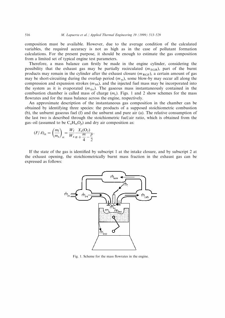
composition must be available. However, due to the average condition of the calculatedvariables, the required accuracy is not as high as in the case of pollutant formationcalculations. For the present purpose, it should be enough to estimate the gas compositionfrom a limited set of typical engine test parameters.Therefore, a mass balance can ®rstly be made in the engine cylinder, considering the
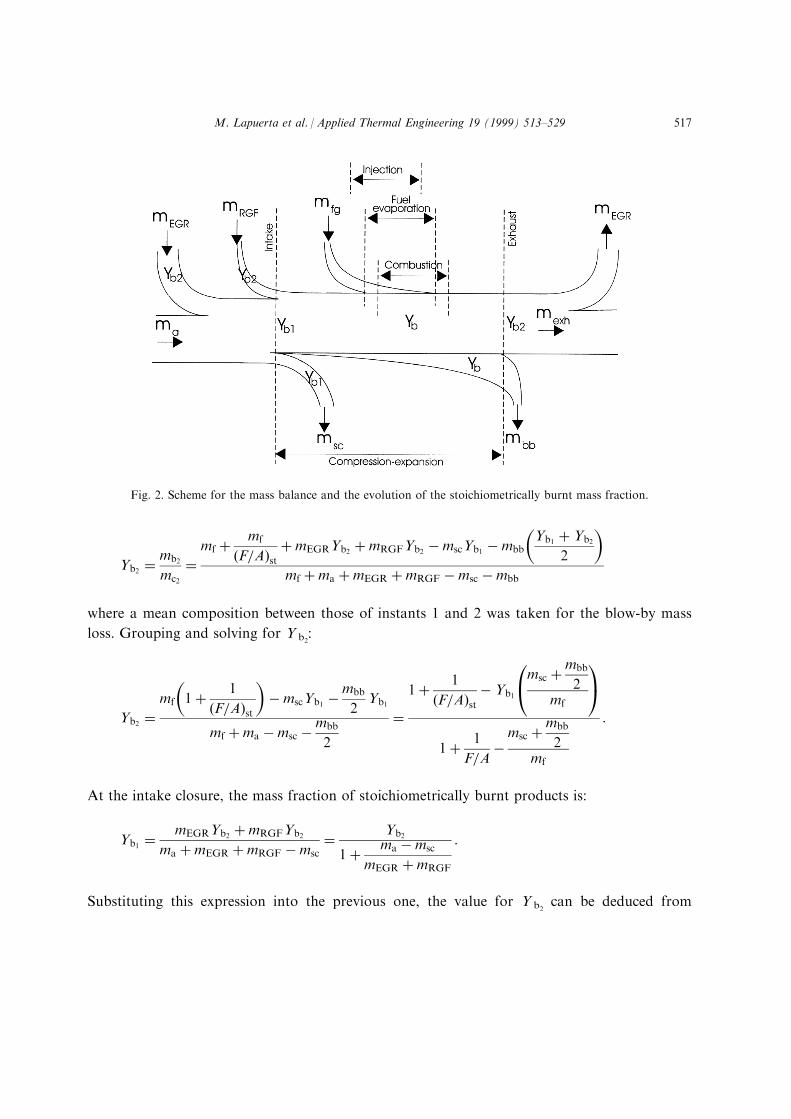
possibility that the exhaust gas may be partially recirculated (mEGR), part of the burntproducts may remain in the cylinder after the exhaust closure (mRGF), a certain amount of gasmay be short-circuiting during the overlap period (m sc), some blow-by may occur all along thecompression and expansion strokes (m bb), and the injected fuel mass may be incorporated intothe system as it is evaporated (m fev). The gaseous mass instantaneously contained in thecombustion chamber is called mass of charge (mc). Figs. 1 and 2 show schemes for the mass¯owrates and for the mass balance across the engine, respectively.An approximate description of the instantaneous gas composition in the chamber can be
obtained by identifying three species: the products of a supposed stoichiometric combustion(b), the unburnt gaseous fuel (f) and the unburnt and pure air (a). The relative consumption ofthe last two is described through the stoichiometric fuel/air ratio, which is obtained from thegas±oil (assumed to be CnHmOp) and dry air composition as:
�F=A�st �mf
ma
� �st
� Wf
Wa
Xa�O2�n�m
4ÿ p
2
:
If the state of the gas is identi®ed by subscript 1 at the intake closure, and by subscript 2 atthe exhaust opening, the stoichiometrically burnt mass fraction in the exhaust gas can beexpressed as follows:
Fig. 1. Scheme for the mass ¯owrates in the engine.
M. Lapuerta et al. / Applied Thermal Engineering 19 (1999) 513±529516
Yb2 �mb2
mc2
�mf � mf
�F=A�st�mEGRYb2 �mRGFYb2 ÿmscYb1 ÿmbb
Yb1 � Yb2
2
� �mf �ma �mEGR �mRGF ÿmsc ÿmbb
where a mean composition between those of instants 1 and 2 was taken for the blow-by mass
loss. Grouping and solving for Y b2:
Yb2 �mf 1� 1
�F=A�st
� �ÿmscYb1 ÿ
mbb
2Yb1
mf �ma ÿmsc ÿmbb
2
�1� 1
�F=A�stÿ Yb1
msc �mbb
2mf
0@ 1A1� 1
F=Aÿmsc �mbb
2mf
:
At the intake closure, the mass fraction of stoichiometrically burnt products is:
Yb1 �mEGRYb2 �mRGFYb2
ma �mEGR �mRGF ÿmsc� Yb2
1� ma ÿmsc
mEGR �mRGF
:
Substituting this expression into the previous one, the value for Y b2can be deduced from
Fig. 2. Scheme for the mass balance and the evolution of the stoichiometrically burnt mass fraction.
M. Lapuerta et al. / Applied Thermal Engineering 19 (1999) 513±529 517
known parameters:
Yb2 �1� 1
�F=A�st
1� 1
F=Aÿ
msc �mbb
2mf
0@ 1A 1
1 � mEGR �mRGF
ma ÿmsc
:
Finally, in an intermediate instant (i) between the intake closure and the exhaust closure, theconcentration of stoichiometrically burnt products can be written as a function of the heatrelease fraction, as it is one of the variables which are handled during the diagnosis of theengine combustion process:
Yb � mb
mc�
mf � mf
�F=A�st
� �HRF�mEGRYb2 �mRGFYb2 ÿmscYb0 ÿ
�i1
Ybdmbb�i1
dmfev �ma �mEGR �mRGH ÿmsc ÿ�i1
dmbb
�mf � mf
�F=A�st
� �HRF� �mEGR �mRGH�Yb2 ÿ msc �m*bb
2
� �Yb1
m*fev �ma �mEGR �mRGF ÿ msc �m*bb
2
� �where the accumulated quantities in the blow-by and fuel evaporation processes up to thepresent instant are indicated by an asterisk.
Otherwise, the unburnt gaseous fuel mass fraction is zero at instants 1 (as injection has notstarted yet) and 2 (as the injected fuel is assumed to be completely burnt), whilst at anintermediate instant it can be obtained as a function of the instantaneous heat release fraction:
Yf � m*fg ÿmfHRF
m*fg �ma �mEGR �mRGF ÿmsc ÿm*bb
being always possible to deduce the instantaneous pure air mass fraction from
Ya � 1ÿ Yb ÿ Yf:
The values of mass per stroke of inlet air (ma), injection fuel (mf ) and recirculated gas(m EGR) are obtained from direct measurement in the engine test bed. Those for the residualgas (mRGF) and short-circuiting (m cc) are obtained from a ®lling and emptying model appliedto automotive engines [10]. The instantaneous mass of evaporated fuel (m fev) is calculated froma simple model which ®rstly converts the experimental needle lift signal into an injection rateone (forcing the total injected mass to agree with the measured one in a gravimetric fuel
M. Lapuerta et al. / Applied Thermal Engineering 19 (1999) 513±529518
meter), and secondly, calculates the lag due to atomisation and evaporation from thethermodynamic conditions in the cylinder and the injection characteristics [11].For the determination of the blow-by mass loss (m bb) an isentropic discharge through a
nozzle connecting the cylinder with the carter was supposed:
_mbb � CbbAeff
�����������������������������������������������������������������������������������������2 � ggÿ 1
� p2
RcT
��pcarterp
�2=g
ÿ�pcarterp
��g�1�=g�swhere C bb is a coe�cient to be adjusted by comparison with experimental measurement ofblow-by, and A e� is the e�ective section of the cylinder-ring clearance which was assumed toremain constant as: A e�=3.5�10ÿ6�D, this being the cylinder diameter [12].
4. Thermodynamic properties of the gas
4.1. Gas constant
The gas constant for the gas contained in the chamber can be instantaneously calculatedfrom the gas constants of its constituents, and from their respective mass fractions:
Rc � RaYa � RfYf � RbYb
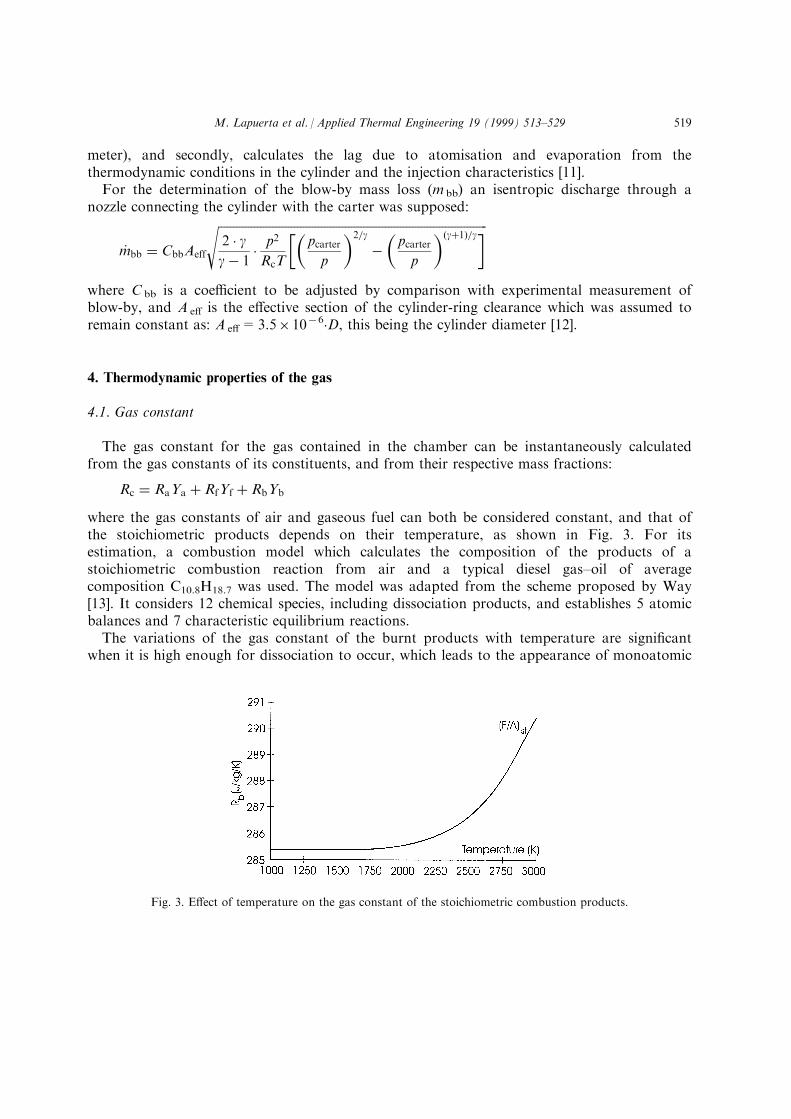
where the gas constants of air and gaseous fuel can both be considered constant, and that ofthe stoichiometric products depends on their temperature, as shown in Fig. 3. For itsestimation, a combustion model which calculates the composition of the products of astoichiometric combustion reaction from air and a typical diesel gas±oil of averagecomposition C10.8H18.7 was used. The model was adapted from the scheme proposed by Way[13]. It considers 12 chemical species, including dissociation products, and establishes 5 atomicbalances and 7 characteristic equilibrium reactions.The variations of the gas constant of the burnt products with temperature are signi®cant
when it is high enough for dissociation to occur, which leads to the appearance of monoatomic
Fig. 3. E�ect of temperature on the gas constant of the stoichiometric combustion products.
M. Lapuerta et al. / Applied Thermal Engineering 19 (1999) 513±529 519
species, with low molecular weight. However, as the mean temperature in the cylinder is neverhigh enough to expect a signi®cant increase on the gas constant, it is acceptable to adopt a®xed value for this constant, the same as for air and fuel:
Rf � R
Wf� 55:95 J=kg K; Ra � R
Wa� 287 J=kg K; Rb � R
Wb� 285:4 J=kg K:
4.2. Speci®c heat
Similarly to the case of the gas constant, the speci®c heat at constant volume, which isneeded for determining the gas internal energy, can be calculated from those of its componentsand their respective mass fractions:
Cvc � CvaYa � CvfYf � CvqYq:
Each component speci®c heat is obtained from polynomial correlations with temperatureCp(T) for pure chemical species. In the case of burnt products, the correlations used for the 12considered species (N2, O2, CO2, H2O, CO, H2, NO, OH, N, H, O, Ar) have the followingshape:
Cp � R�a1T 0:5 � a2 � a3Tÿ0:5 � a4T
ÿ1 � a5Tÿ1:5�:
The coe�cients ai for all species, as well as their standard enthalpy, were obtained byadjusting data taken from Janaf [14], which collect experimental values for Cp in the range of0±6000 K. More recently revised data by Sandia [15] provide more accurate adjustments,although the agreement between both sources was good enough for the present application.It can be easily proved that new coe�cients can be obtained for gaseous mixture
correlations, by weighting each component coe�cient with its molar fraction. In the case ofdry air:
�ai�a � �ai�N2Xa�N2� � �ai�O2
Xa�O2� � �ai�CO2Xa�CO2� � �ai�ArXa�Ar�:
This procedure was not adequate in the case of the stoichiometric products because theircomposition depends on their temperature as a consequence of dissociation. In this case, a 3rddegree correlation was directly obtained from the averaged speci®c heat at constant volume ofburnt products, whose composition was obtained by the above mentioned combustion model.In the case of gaseous fuel, the correlation used has the following shape:
Cp � R�a1 � a2T� a3T2 � a4T
3 � a5Tÿ2�:
The results presented in this work were all obtained with the mentioned gas±oil of averagedcomposition C10.8H18.7, whose coe�cients and standard enthalpy were obtained from
M. Lapuerta et al. / Applied Thermal Engineering 19 (1999) 513±529520
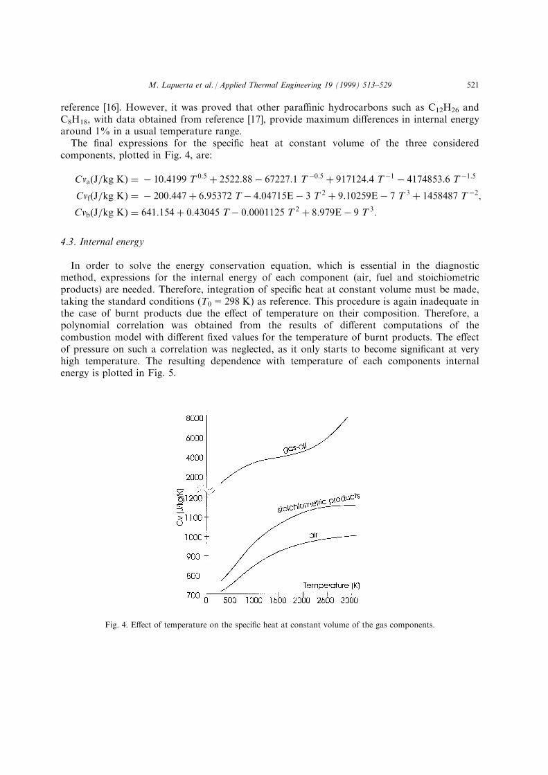
reference [16]. However, it was proved that other para�nic hydrocarbons such as C12H26 andC8H18, with data obtained from reference [17], provide maximum di�erences in internal energyaround 1% in a usual temperature range.The ®nal expressions for the speci®c heat at constant volume of the three considered
components, plotted in Fig. 4, are:
Cva�J=kg K� � ÿ 10:4199 T 0:5 � 2522:88ÿ 67227:1 T ÿ0:5 � 917124:4 T ÿ1 ÿ 4174853:6 T ÿ1:5
Cvf�J=kg K� � ÿ 200:447� 6:95372 Tÿ 4:04715Eÿ 3 T 2 � 9:10259Eÿ 7 T 3 � 1458487 T ÿ2;
Cvb�J=kg K� � 641:154� 0:43045 Tÿ 0:0001125 T 2 � 8:979Eÿ 9 T 3:
4.3. Internal energy
In order to solve the energy conservation equation, which is essential in the diagnosticmethod, expressions for the internal energy of each component (air, fuel and stoichiometricproducts) are needed. Therefore, integration of speci®c heat at constant volume must be made,taking the standard conditions (T0=298 K) as reference. This procedure is again inadequate inthe case of burnt products due the e�ect of temperature on their composition. Therefore, apolynomial correlation was obtained from the results of di�erent computations of thecombustion model with di�erent ®xed values for the temperature of burnt products. The e�ectof pressure on such a correlation was neglected, as it only starts to become signi®cant at veryhigh temperature. The resulting dependence with temperature of each components internalenergy is plotted in Fig. 5.
Fig. 4. E�ect of temperature on the speci®c heat at constant volume of the gas components.
M. Lapuerta et al. / Applied Thermal Engineering 19 (1999) 513±529 521
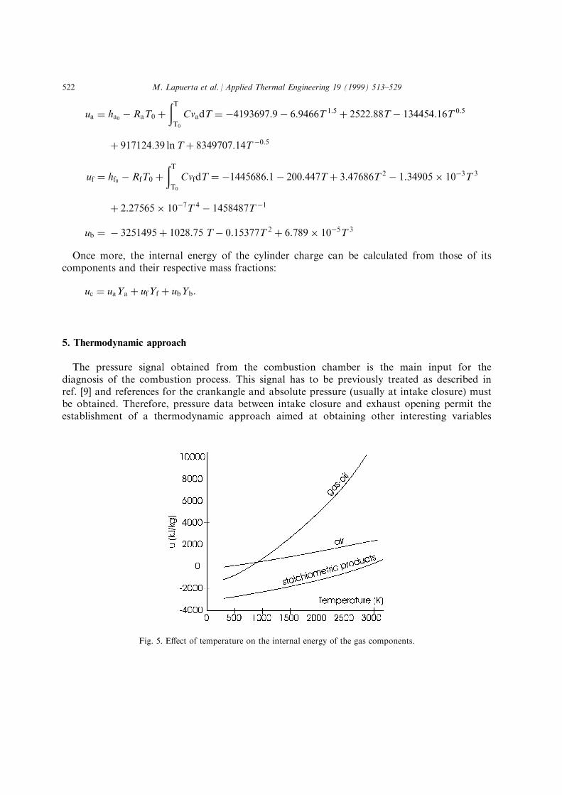
ua � ha0 ÿ RaT0 ��TT0
CvadT � ÿ4193697:9ÿ 6:9466T 1:5 � 2522:88Tÿ 134454:16T 0:5
� 917124:39 lnT� 8349707:14T ÿ0:5
uf � hf0 ÿ RfT0 ��TT0
CvfdT � ÿ1445686:1ÿ 200:447T� 3:47686T 2 ÿ 1:34905� 10ÿ3T 3
� 2:27565� 10ÿ7T 4 ÿ 1458487T ÿ1
ub � ÿ 3251495� 1028:75 Tÿ 0:15377T 2 � 6:789� 10ÿ5T 3
Once more, the internal energy of the cylinder charge can be calculated from those of itscomponents and their respective mass fractions:
uc � uaYa � ufYf � ubYb:
5. Thermodynamic approach
The pressure signal obtained from the combustion chamber is the main input for thediagnosis of the combustion process. This signal has to be previously treated as described inref. [9] and references for the crankangle and absolute pressure (usually at intake closure) mustbe obtained. Therefore, pressure data between intake closure and exhaust opening permit theestablishment of a thermodynamic approach aimed at obtaining other interesting variables
Fig. 5. E�ect of temperature on the internal energy of the gas components.
M. Lapuerta et al. / Applied Thermal Engineering 19 (1999) 513±529522
such as the mean gas temperature and the instantaneously burnt mass. The presence of blow-by and the incorporation into the system of the injected fuel, force us to consider the system asan open one:
d�mcuc� � ÿp dVÿ dQw ÿ hcdmbb � h�njdmfev
where the incorporation of gaseous fuel comes together with the enthalpy of the liquid fuelduring injection, h ®nj, in order to take into account the contribution of the whole injectionprocess to the energy of the system.Although the present approach is a single-zone one (a single mean gas temperature is
considered) the distinction of three species in the chamber with di�erent thermodynamicproperties permits the following decomposition:
d�mcuc� � madua �mfduf �mbdub � uadma � ufdmf � ubdmb: �1�
The following identities between the involved mass of species can be written, where dm ab anddm fb are two intermediate variables which indicate the mass consumption of air and fuelexclusively due to stoichiometric burning:
dmb � dmab � dmfb ÿ Ybdmbb;
dma � ÿ dmab ÿ Yadmbb;
dmf � ÿ dmfb � dmfev ÿ Yf dmbb;
dmfb � �F=A�stdmab:
By combining these equations it is possible to express the variations of air and fuel mass as afunction of that of the stoichiometric combustion products:
dma � ÿ1�F=A�st � 1
�dmb � Ybdmbb� ÿ Yadmbb;
dmf � ÿ�F=A�st�F=A�st � 1
�dmb � Ybdmbb� � dmfev ÿ Yfdmbb:
Substituting into Eq. (1), grouping, and expressing the internal energy variations as afunction of the speci®c heat at constant volume
d�mcuc� � mc�YaCvadT� YfCvfdT� YbCvdT� � ub ÿ uf�F=A�st � ua�F=A�st � 1
� ��dmb � Ybdmbb�
� ufdmfev ÿ �Yaua � Yfuf � Ybub�dmbb
and retaking the expressions for mean speci®c heat and internal energy of the gas obtained inparagraph 3, the ®rst principle equation becomes:
M. Lapuerta et al. / Applied Thermal Engineering 19 (1999) 513±529 523
mcduc � ub ÿ uf�F=A�st � ua�F=A�st � 1
� ��dmb � Ybdmbb�
� ÿp dVÿ dQw � �h�nj ÿ uf�dmfev ÿ RcT dmbb
where the second term from the left corresponds, with opposite sign, to the combustion heatrelease, which can be solved in each instant, by combination of this equation with the stateequation. Further on, the burnt mass can also be obtained from the heat release term.The e�ect of injection on the energy balance has a negative contribution (the heating and
vaporization of the fuel) and a positive one (the ¯ow work). The enthalpy of the liquid fuel atthe injection temperature (supposed to be around 30 K above the fuel temperature at the pumpin the experimental tests) can be obtained from direct integration of the speci®c heat atconstant pressure of the gaseous fuel until the boiling temperature:
hfinj � Cpfliq�Tinf ÿ Tvap� ÿ hvap � hf0 ��Tb
T0
Cp dT:
6. Results
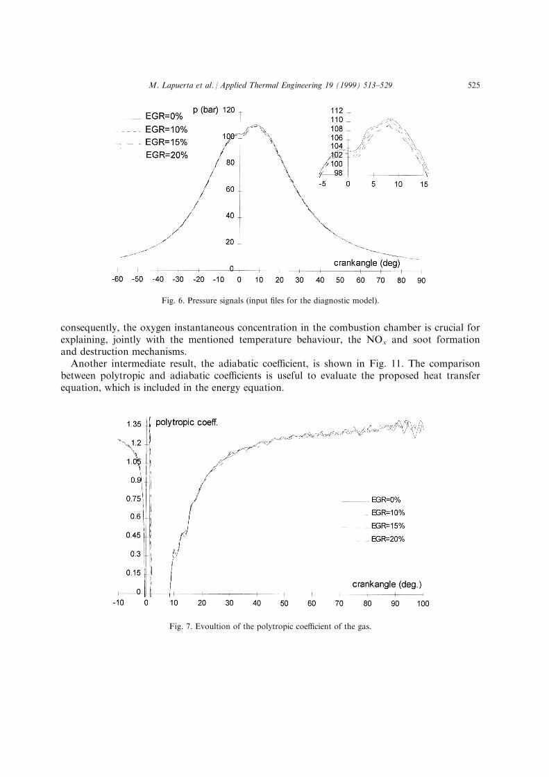
As an example of application of the proposed method, the results of the diagnosis of thecombustion process of a turbocharged 0.6 l/cylinder direct injection diesel engine, whichbelongs to a type of engine that is becoming more and more common in passenger cars inEurope, tested at 2500 rpm and partial load and with di�erent EGR levels, are presented. Fueldelivery was kept constant during the whole set of tests (27 mg/cycle), and the intake airreduced as EGR was increased. Fig. 6 shows the measured combustion chamber pressuresignals. Very small di�erences can be appreciated in this plot, these being mainly justi®ed by aslight increase of delay time and a slight reduction of combustion velocity for increasing EGRlevels. Also very small di�erences can be appreciated in the polytropic coe�cient (Fig. 7), as itis no more than a combination of pressure and cylinder volume signals.Figs. 8 and 9 show the main results of the combustion diagnostic method, such as the
evolution along the crankangle of the released heat (heat release fraction, HRF, if nondimensional with respect to the fuel calori®c power) and the mean temperature in the chamber.The former permits a more clear quanti®cation of the mentioned e�ects of EGR on thecombustion timing. In addition, as far as the heat release rate can be controlled through theengine or the injection system design (modern electronically programmed injection systemshave an increasing capacity to do it [18]), an optimization process can be performed in termsof bmep, noise and smoke emissions, etc. [19]. The latter is helpful for explaining thesigni®cant reduction of NOx as EGR is increased, and can help engine optimization in terms ofexhaust energy, emissions, etc.Finally, as an intermediate result, Fig. 10 shows the evolution of the mass fractions of air
and stoichiometric products (that of the fuel remains always very small). It can be noticed thatthe air mass fraction starts from values below unity due to RGF and EGR, and remainspositive until the end of combustion due to air excess. The quanti®cation of the air, and
M. Lapuerta et al. / Applied Thermal Engineering 19 (1999) 513±529524
consequently, the oxygen instantaneous concentration in the combustion chamber is crucial forexplaining, jointly with the mentioned temperature behaviour, the NOx and soot formationand destruction mechanisms.Another intermediate result, the adiabatic coe�cient, is shown in Fig. 11. The comparison
between polytropic and adiabatic coe�cients is useful to evaluate the proposed heat transferequation, which is included in the energy equation.
Fig. 6. Pressure signals (input ®les for the diagnostic model).
Fig. 7. Evoultion of the polytropic coe�cient of the gas.
M. Lapuerta et al. / Applied Thermal Engineering 19 (1999) 513±529 525
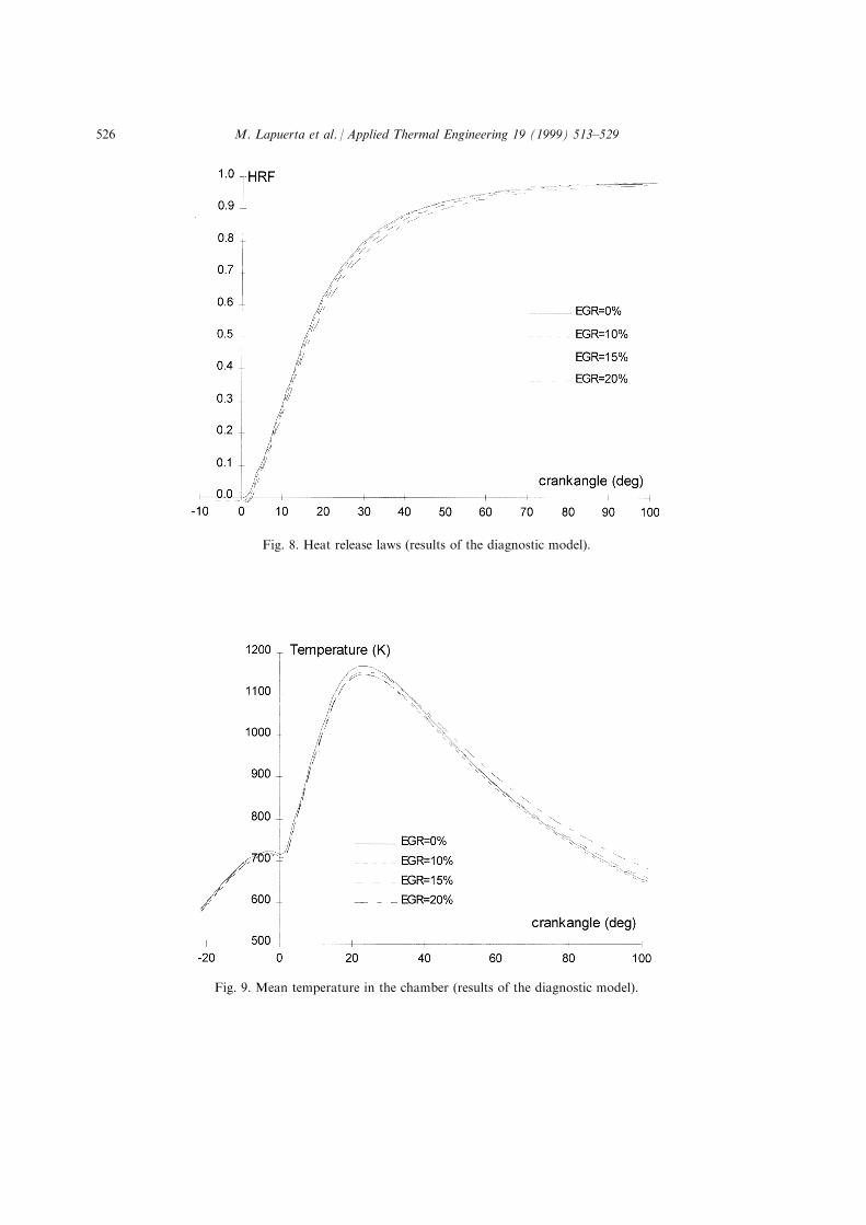
Fig. 8. Heat release laws (results of the diagnostic model).
Fig. 9. Mean temperature in the chamber (results of the diagnostic model).
M. Lapuerta et al. / Applied Thermal Engineering 19 (1999) 513±529526
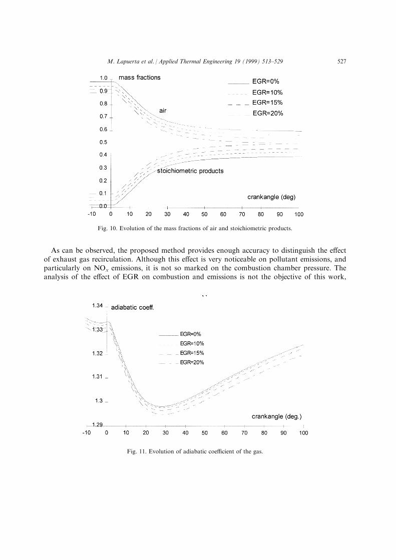
As can be observed, the proposed method provides enough accuracy to distinguish the e�ectof exhaust gas recirculation. Although this e�ect is very noticeable on pollutant emissions, andparticularly on NOx emissions, it is not so marked on the combustion chamber pressure. Theanalysis of the e�ect of EGR on combustion and emissions is not the objective of this work,
Fig. 10. Evolution of the mass fractions of air and stoichiometric products.
Fig. 11. Evolution of adiabatic coe�cient of the gas.
M. Lapuerta et al. / Applied Thermal Engineering 19 (1999) 513±529 527
and can be found in ref. [20], based on a complete experimental programme with a widerengine conditions range.
7. Conclusions
A method for performing a quick thermodynamic diagnosis of the combustion process in aDI diesel engine has been developed. This method takes into account the time variation of thethermodynamic properties of the gas as a function of its instantaneous composition and theinstantaneous mass balance in the combustion chamber.The proposed method provides enough sensitivity to re¯ect the exclusive e�ect on the heat
release rate, and on the mean thermodynamic variables in the chamber, of engine operatingparameters related to the composition of the gas, such as the exhaust gas recirculation, thisbeing a technique of increasing interest. The quanti®cation of these e�ects is helpful forunderstanding the mechanisms governing emissions, and enables an engine optimizationprocess.
References
[1] K. Iida, K. Akishino, K. Kido, IMEP estimation from instantaneous crankshaft torque variation. SAE paper900617, 1990.
[2] S.J. Citron, J.E. O'Higgins, L.Y. Chen, Cylinder by cylinder engine pressure and pressure torque waveform
determination utilizing speed ¯uctuations. SAE paper 890486, 1989.[3] K. Asano, Y. Ito, T. Tsunoda, I. Suzuki, Advanced diagnostic system for cogeneration. 1995 International Gas
Research Conference, 1995.
[4] P.M. Azzoni, G. Cantoni, G. Minelli, D. Moro, Indirect pressure measurement in a small diesel engine. 47,ATA Ingenieria Automotoristica, 1994.
[5] R.B. Krieger, G.L. Borman, The computation of apparent heat release for internal combustion engines. ASME
paper 66-WA/DGP-4, 1966.[6] D.N. Assanis, J.B. Heywood, Development and use of computer simulation of the turbocompounded diesel
system for engine performance and component heat transfer studies. SAE paper 860329, 1986.[7] F.V. Tinaut, Contribucio n al estudio del proceso de combustio n en motores de encendido por compresio n de
inyeccio n directa, PhD thesis. Universidad Polite cnica de Valencia, 1986.[8] H.M. Cheung, J.B. Heywood, Evaluation of a one-zone burn-rate analysis procedure using production SI
engine pressure data. SAE paper 932749, 1993.
[9] F. Payri, R. Desantes, A. Leiva, O. Armas, Modelo termodina mico para el diagno stico experimental del pro-ceso de combustio n en motores diesel ID. Congreso Iberoamericano de Ingenierõ a Meca nica, 1997.
[10] F. Payri, J.M. Desantes, J.M. Corbera n, A quasi-steady model on gas-exchange process, some results. Motor
Sympo'88, Praghe, 1988.[11] B. Gime nez, Caracterizacio n y modelado de la formacio n de chorros atomizados intermitentes con evaporacio n,
PhD thesis. Universidad de Valladolid, 1997.[12] G. Hohenberg, De®nition und Eigenschaften des thermodynamischen Verlutwinkels von Kolbenmaschinen.
AVL Graz, Austria, 1984.[13] R.J.B. Way, Methods for the determination of composition and thermodynamic properties of combustion pro-
ducts for internal combustion engine calculations. Proc. Inst. Mech. Engrs. 190(60/76) 687±697, 1977.
[14] DOW Chemical Company, Janaf Thermochemical Tables, 1962, Addendum, 1966.[15] R.J. Kee, F.M. Rupley, J.A. Miller, The Chemkin thermodynamic data base. Sandia Report, SAND87-8215B,
1991.
M. Lapuerta et al. / Applied Thermal Engineering 19 (1999) 513±529528

[16] J.B. Heywood, Internal Combustion Engine Fundamentals. McGraw-Hill, New York, 1988.[17] R.C. Reid, J.M. Prausnitz, B.E. Poling, The properties of Gases and Liquids. 4th ed., McGraw-Hill, New
York, 1987.[18] L.O. Hoppie, Y.K. Min, N. Srinivasan, S.H. Wu, Optimum heat release for a reciprocating internal combustion
engine. SAE paper 870572, 1987.
[19] J.M. Desantes, F.V. Tinaut, M. Lapuerta, Optimisation de la combustion dans un moteur diesel aÁ injectiondirecte suralimente par utilisation de lois de combustion, Entropie 27 (161) (1991).
[20] F. Payri, M. Lapuerta, Ph Cazaux, Insight into the combustion process of a diesel engine with exhaust gas
recirculation. 5th International EAEC Congress, Strasbourg, SIA paper 9506A13, 1995.
M. Lapuerta et al. / Applied Thermal Engineering 19 (1999) 513±529 529