
DFM – Weldability analysis and system development - DiVA
65
Postadress: Besöksadress: Telefon: Box 1026 Gjuterigatan 5 036-10 10 00 (vx) 551 11 Jönköping DFM – Weldability analysis and system development Venkata Krishna Rao Pabolu EXAM WORK 2015 Product Development and Materials Engineering
-
Upload
khangminh22 -
Category
Documents
-
view
3 -
download
0
Transcript of DFM – Weldability analysis and system development - DiVA

Postadress: Besöksadress: Telefon: Box 1026 Gjuterigatan 5 036-10 10 00 (vx) 551 11 Jönköping
DFM – Weldability analysis and system development
Venkata Krishna Rao Pabolu
EXAM WORK 2015 Product Development and Materials Engineering
Postadress: Besöksadress: Telefon: Box 1026 Gjuterigatan 5 036-10 10 00 (vx) 551 11 Jönköping
This exam work has been carried out at the School of Engineering in Jönköping in the subject area Product Development and Materials Engineering. The work is a part of the two-year Master of Science programme in the University. The authors take full responsibility for opinions, conclusions and findings presented. Examiner: Fredrik Elgh Supervisor: Roland Stolt Scope: 30 credits Date:
Abstract
I
Abstract
The proposed thesis is a sub part of a research project named “IMPACT”. The research project is related to the product development processes and methods. This thesis work is mainly focused on the processes involved in manufacturing of aircraft engine components. The processes are especially about welding and welding methods. The basics of welding and the thesis support has been taken from the GKN Aerospace Sweden AB, a global aerospace product supplier. The basic objective of this thesis work is to improve the usability of an automation system which is developed for evaluating the weldability of a part. A long run maintainability aspect of this automation system has been considered.
The thesis work addresses the problems arising during the usage of a computerised automated system such as process transparency, recognisability, details traceability and other maintenance aspects such as maintainability and upgradability of the system in the course of time.
The action research methodology has been used to address these problems. Different approaches have been tried to finding the solution to those problems. A rule based manufacturability analysis system has been attempted to analyse the weldability of a component in terms of different welding technics.
The software “Howtomation” has been used to improve the transparency of this analysis system. User recognisability and details tractability have been taken into account during the usage of a ruled based analysis system. The system attributes such as maintainability, upgradability, adaptiveness to modern welding methods has been addressed. The system suitability for large scale analysis has been considered. Keywords Design for Manufacturing, Weldability, Design Automation, Knowledge Based Engineering, Rule Based Analysis System, System Maintainability

Contents
II
Contents
1 Introduction ............................................................................. 1
1.1 BACKGROUND ................................................................................................................................................. 1 1.2 ABOUT THE COMPANY ................................................................................................................................... 3 1.3 PROBLEM DESCRIPTION ................................................................................................................................ 5 1.4 PURPOSE AND RESEARCH QUESTIONS ......................................................................................................... 7 1.5 DELIMITATIONS............................................................................................................................................... 8 1.6 OUTLINE ........................................................................................................................................................... 9
2 Theoretical background ........................................................ 10
2.1 DESIGN AUTOMATION SYSTEMS ................................................................................................................ 13 2.2 KNOWLEDGE BASED ENGINEERING SYSTEMS ....................................................................................... 14 2.3 MULTIDISCIPLINARY ANALYSIS SYSTEM ................................................................................................... 15 2.4 MANUFACTURABILITY ASSESSMENT SYSTEMS ......................................................................................... 18
3 Methods and implementation ............................................... 21
3.1 DESIGN RESEARCH METHODOLOGY (DRM) .......................................................................................... 21 3.2 ACTION RESEARCH ....................................................................................................................................... 23 3.3 APPLICATION OF RESEARCH METHOD AND PROJECT IMPLEMENTATION ........................................ 24
3.3.1 Identification of requirement: ................................................................................................................... 25 3.3.2 Analysing the requirements and determining some relevant factors............................................................ 25 3.3.3 Formulating tentative ideas for execution ................................................................................................. 26 3.3.4 Gathering and interpreting data to make first action plan ....................................................................... 29 3.3.5 Action Cycles for Software development ................................................................................................... 33 3.3.6 Evaluating the results of the actions ......................................................................................................... 40
4 Findings and analysis .............................................................. 41
4.1 DFM – WELDABILITY ANALYSIS PROCESS DESCRIPTION ...................................................................... 41 4.2 PROTOTYPE DESCRIPTION .......................................................................................................................... 44 4.3 COST ESTIMATIONS ...................................................................................................................................... 47 4.4 INPUTS TO FIND WELDABILITY INDEX ...................................................................................................... 47
5 Discussion and conclusions ................................................... 49
5.1 DISCUSSION OF METHOD ............................................................................................................................. 49 5.2 DISCUSSION OF FINDINGS ........................................................................................................................... 50
5.2.1 Transparency........................................................................................................................................... 50 5.2.2 Recognisability......................................................................................................................................... 50 5.2.3 Traceability ............................................................................................................................................. 51 5.2.4 Upgradability .......................................................................................................................................... 51 5.2.5 Other Requirements ................................................................................................................................ 51 Scalability ................................................................................................................................................................ 51 Cost analysis............................................................................................................................................................ 52 Batch mode compatibility ......................................................................................................................................... 52 Weldability Index .................................................................................................................................................... 52
5.3 CONCLUSIONS ................................................................................................................................................ 53 5.4 FUTURE WORK .............................................................................................................................................. 53
6 References .............................................................................. 54
7 Appendices ............................................................................. 58

Nomenclature
1
Nomenclature
AI Artificial Intelligence
CAE Computer-Aided Engineering
CAD Computer Aided Design
DA Design Automation
DI Difficulty Index
DL Difficulty Level
DP Design Practices DoE Design of Experiment
DFM Design for Manufacturing DFP Design for Producibility DRM Design Research Methodology
EWB Engineering Workbench
ES Expert System ETO Engineer to Order FMEA Failure Modes and Effects Analysis KBE Knowledge Based Engineering KIC Knowledge Intensive CAD systems LBM Laser Beam Method
MAS Manufacturability Analysis System
MIG Metal Inert Gas
MOKA Methodology and software tools Oriented to Knowledge based
engineering Applications
OEM Original Equipment Manufacturer
PDM Product Data Management
PLM Product Lifecycle Management RFQ Request for Quotation SBCE Set-Based Concurrent Engineering
TIG Tungsten Inert Gas welding TOICA Thermal Overall Integrated Conception of Aircraft VAR Value-Added Resellers
VBA Visual Basic for Applications
Introduction
1
1 Introduction ************************************************************************** The Introduction chapter contains basic details of the project work followed by the thesis background, company background, thesis purpose and objectives, delimitations and an overall project outline.
**************************************************************************
There are several challenges to the manufacturing industry in order to sustain in the competitive environment, in terms of cost, technology level, development time, manufacturing ability, etc. As a manufacturing part supplier, it is required to meet consumer requirements and provide new products with new technical solutions in a competitive environment [1]. The research projects “IMPACT” and “ChaSE” from the School of Engineering, Jönköping University are intended to find suitable ways to meet the current challenges of the Swedish industry with new effective methods. Those methods shall meet current challenges such as product customisation [1], changing and conflicting requirements, adapting new updated technologies to new products [2] and their effectively developments.
Design Automation [3], Knowledge based engineering [4], Design for Manufacturing (DFM) [5] are some recent improvements in the manufacturing industry to meet current challenges in terms of cost, product customisation and development time. The purpose of this project is to develop an automated manufacturability analysis system in terms of manufacturability assessment especially about the weldability.
Another problem with an automated system is upgradability. Once the automation has been done on the basis of current standards, it is difficult to update the automation procedures according to the changing environment and requirements. Therefore, the automated analysis system must be an adaptive type to meet the current requirements. For this purpose the proposed thesis also considers usability and upgradability aspects in computerised automated weldability analysis system.
1.1 Background The primary objective of a product or design solution is to meet the customer needs effectively. The needs of a customer often do changes from time to time. In the case of customized products such as aerospace engineer-to-order (ETO) products, the product designers have to consider a broad range of new design solutions. Douglas H et al. [6] has emphasised the job complexity in customised products, especially for ETO process in his research work. Brière-Côté et al. [7] have described an adaptive generic product structure modelling for design and reuse of engineer-to-order products and product knowledge. However, this requires the development and integration of knowledge-based enabling technologies.
Introduction
2
Considering the above concerns, the Department of Product Development, Jönköping University is currently focusing on two major research projects headed by Prof. Fredrik Elgh. The projects are related to product development processes and methods. Both of those two research projects are collaborations with, among others and one of the industrial partners is GKN Aerospace AB, Sweden. The first project is named “IMPACT” which addresses issues related to knowledge management. The other project is “ChaSE” which deals with the meeting of changing requirements in product development.
The core objective of the project “ChaSE” is to understand the challenges of Swedish Industry in terms of product and technology development and to propose new methods to increase ability to meet changing requirements.
The basic objective of the “IMPACT” project is to devise and refine the concepts and tools needed to support the modelling, management and exploitation of information and knowledge. Examples include knowledge access, knowledge interpretation, knowledge updatability and the traceability of changes in the knowledge base.
GKN Aerospace, Sweden, is one of the project partners to these research projects. The contribution from GKN is to support the project regarding traceability, information and knowledge access and interpretation. GKN has done extended research about Knowledge Access, Knowledge modelling and application of knowledge systems in the engineering applications. GKN is working to introduce knowledge based engineering systems to meet the ETO requirements of Aerospace products. On the way to meet ETO requirements Tim Heikkinen and Jakob Müller [8] have written their thesis with GKN which is entitled as “Assessment of Multidisciplinary Analysis Systems in Aerospace engineering Products”. The Multidisciplinary Analysis Systems is an application of several advanced techniques such as Knowledge Based Engineering (KBE) [4], Artificial Intelligence (AI) [3], MOKA [9], Set-Based Concurrent Engineering [10], Design of Experiment (DoE) and Design Automation. The details of Multidisciplinary Analysis Systems have been explained in the section 2.3. Manufacturability analysis is a part of the multidisciplinary analysis systems and the weldability analysis is the sub part of the Manufacturability analysis system (Figure 2-1).
The thesis work is an extension part of Multidisciplinary Analysis Systems in terms of weldability analysis. Weldability analysis system development, managing and interpretation of knowledge related to the weldability analysis in terms traceability and updatability will be the primary part to this thesis work. Introduction of knowledge systems in the engineering applications, knowledge management, knowledge modelling are the fundamental part of the main research project i.e. “IMPACT” and which is also supported by GKN Aerospace, Sweden.
Introduction
3
1.2 About the company
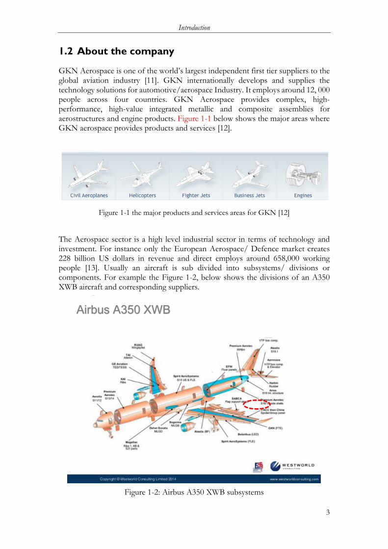
GKN Aerospace is one of the world’s largest independent first tier suppliers to the global aviation industry [11]. GKN internationally develops and supplies the technology solutions for automotive/aerospace Industry. It employs around 12, 000 people across four countries. GKN Aerospace provides complex, high-performance, high-value integrated metallic and composite assemblies for aerostructures and engine products. Figure 1-1 below shows the major areas where GKN aerospace provides products and services [12].
Figure 1-1 the major products and services areas for GKN [12]
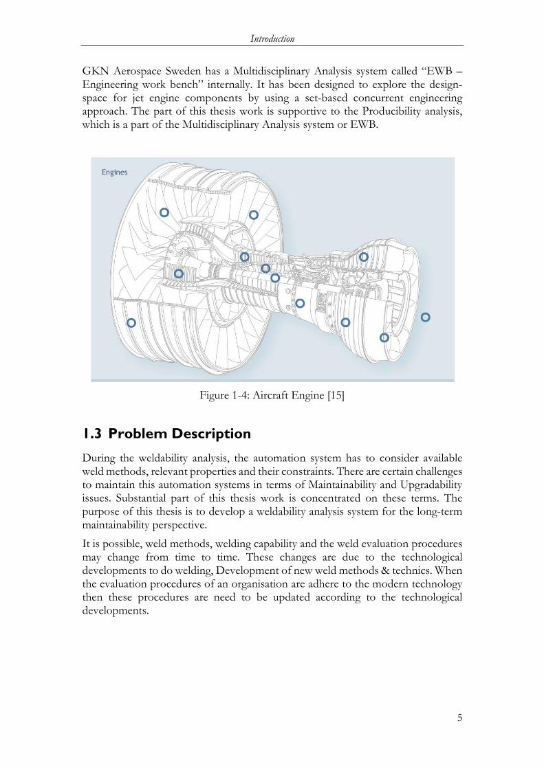
The Aerospace sector is a high level industrial sector in terms of technology and investment. For instance only the European Aerospace/ Defence market creates 228 billion US dollars in revenue and direct employs around 658,000 working people [13]. Usually an aircraft is sub divided into subsystems/ divisions or components. For example the Figure 1-2, below shows the divisions of an A350 XWB aircraft and corresponding suppliers.
Figure 1-2: Airbus A350 XWB subsystems
Airbus A350 XWB

Introduction
4
The supply chain of the aerospace industry usually works in three levels as shown in Figure 1-3 below [13]. First, Original Equipment Manufacturer (OEM) or value-added resellers (VAR) sell the finished or final aircrafts. There are also suppliers and risk sharing partners, who support the OEMs in terms of technology, money, manpower and so on. Finally there are sub suppliers, who trade the goods and technology with OEMs and main suppliers. GKN Aerospace is positioned as a primary supplier to the leading aircraft manufacturers in the world.
Figure 1-3: Aerospace Supply Chain
GKN Aerospace Sweden is part of the GKN Group, which is located at Trollhättan, Sweden. The group consists of four divisions: Aerospace, Land Systems, Driveline and Powder Metallurgy. It was known as Volvo Aero until 2012. The project is a part of the engine division. The highlighted marks in Figure 1-4, are the components of engines that are manufactured by GKN aerospace. The engine division primary focuses on six main functional areas: propulsion system and program management, subsystems and component development for engines, engine systems analysis, high quality analysis of aero and thermos dynamics and structural mechanics, testing of turbine components and production of metallic materials including thermal coatings [14]. This plant is currently working for new nozzle to Vulcain 2.1 engine, which is planned to be used in the Ariane 6 space rocket.
The company has a set of rules or guidelines for each individual process, referred as “Design Practices” (DP). The DPs for welding are the primary inputs to this thesis application, where the weldability evaluation procedures are described.
Introduction
5
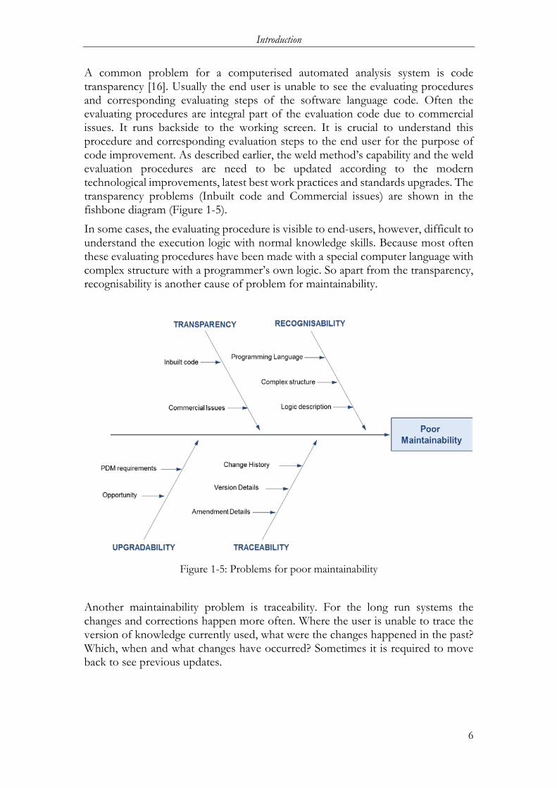
GKN Aerospace Sweden has a Multidisciplinary Analysis system called “EWB –Engineering work bench” internally. It has been designed to explore the design-space for jet engine components by using a set-based concurrent engineering approach. The part of this thesis work is supportive to the Producibility analysis, which is a part of the Multidisciplinary Analysis system or EWB.
Figure 1-4: Aircraft Engine [15]
1.3 Problem Description
During the weldability analysis, the automation system has to consider available weld methods, relevant properties and their constraints. There are certain challenges to maintain this automation systems in terms of Maintainability and Upgradability issues. Substantial part of this thesis work is concentrated on these terms. The purpose of this thesis is to develop a weldability analysis system for the long-term maintainability perspective.
It is possible, weld methods, welding capability and the weld evaluation procedures may change from time to time. These changes are due to the technological developments to do welding, Development of new weld methods & technics. When the evaluation procedures of an organisation are adhere to the modern technology then these procedures are need to be updated according to the technological developments.
Introduction
6
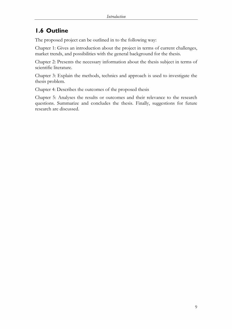
A common problem for a computerised automated analysis system is code transparency [16]. Usually the end user is unable to see the evaluating procedures and corresponding evaluating steps of the software language code. Often the evaluating procedures are integral part of the evaluation code due to commercial issues. It runs backside to the working screen. It is crucial to understand this procedure and corresponding evaluation steps to the end user for the purpose of code improvement. As described earlier, the weld method’s capability and the weld evaluation procedures are need to be updated according to the modern technological improvements, latest best work practices and standards upgrades. The transparency problems (Inbuilt code and Commercial issues) are shown in the fishbone diagram (Figure 1-5).
In some cases, the evaluating procedure is visible to end-users, however, difficult to understand the execution logic with normal knowledge skills. Because most often these evaluating procedures have been made with a special computer language with complex structure with a programmer’s own logic. So apart from the transparency, recognisability is another cause of problem for maintainability.
Figure 1-5: Problems for poor maintainability
Another maintainability problem is traceability. For the long run systems the changes and corrections happen more often. Where the user is unable to trace the version of knowledge currently used, what were the changes happened in the past? Which, when and what changes have occurred? Sometimes it is required to move back to see previous updates.

Introduction
7
Poor upgradability is another important problem related to maintainability. Where the user cannot able to change or improve the system once it has been made. Also the developed system may not suitable to fit into the existing PDM system. Figure 1-5 above shows all of these problems and corresponding route causes in the form of a fishbone diagram for easy understanding.
1.4 Purpose and research questions The purpose of this thesis work is to support the major research projects i.e. “IMPACT” in terms of knowledge management. As described earlier, these projects are intended to find suitable ways to meet the current industrial challenges such as; quick request for quotation (RFQ), Reduction of development time for customised product and the manufacturing cost.
An automated Multi object Analysis system by using KBE system has been developed to meet the challenges. Manufacturability/Producibility Analysis is a sub part of a Multi object Analysis system, to investigate manufacturing suitability of a design or a component. Weldability Analysis is a subpart of the Producibility Analysis. The current Weldability Analysis has some maintainability problems mentioned in the section 1.3 for long-run context. The company’s infrastructure and technological competencies, which are described in the “Design Practices” (DP) by a set of ‘rules’ and guidelines. So that the system must be capable to adapt these changes. For this purpose following features are needed to be included during the system development. Those proposed features are; Transparency, where the user can able to read each and every detail of evaluating procedure. Recognisability, the procedures must be understandable to the end user. Traceability, where the user can find the version and amendment details of procedures. Upgradability, The entire weldability analysis system is capable to upgrade.
Considering the purpose and the thesis time frame, the thesis work focuses on development of DFM-weld analysis system with usability and maintainability aspects. The research question can be outlined as:
How can be the Maintainability aspects such as Transparency, Recognisability, Traceability, and upgradability be introduced into the automated DFM-Weldability analysis system?

Introduction
8
Description of research question The term Transparency has been described as the user can able to read each and every detail of the evaluation. Here, the evaluation has been done with a set of rules and conditions. But, their execution is carried out by a logical relation with a mathematical function. So the meaning for transparency here is, the reader can able to see the logical relation for the execution; either formula or code whatever applicable. The term Recognisability means, the evaluation rules and the logical relation embedded in the evaluation process must be understandable to the end user. It means that the end user must understand the process logical with the fundamental knowledge. In simple terms; The ‘Transparency’ and ‘Recognisability’ refers; ability to see the rule and understanding the rule respectively. Where the term Traceability means the user can find the version and amendment details of evaluation procedure or rules and also the references of evaluation results. Therefore, the user can able to trace the evaluation steps and the corresponding details.
Considering the term maintainability, the automation system must be utilized in the long run within the user company. It may require several changes and amendments in the existing version of the system. The automation system must be capable to accept and digest changes happening in the future by maintaining a certain level of “upgradability”.
1.5 Delimitations
The thesis DFM-weldability analysis and system development primary interest is to develop a system which can evaluate the weldability of a joint while the system must be upgradable and maintainable for the long-run. Also cable to calculate the weld cost, weld process sequence and selection of best weld method by calculating the Manufacturability index. Considering the time, the thesis is subjected to cover the requirements with following limitations.
The rules defined in the thesis as an intelligence system are only a part of a weldability analysis. These rules are not sufficient for a complete analysis of a weld joint. The weld methods defined for weld analysis are very few and the values used to define the weld methods are facetious. They have been used to understand and verify the feasibility of the system in experiment model. The output results can answer in the form of ‘yes’ or ‘no’ form only. Manufacturability index is not covered during the work. The work is limited to analyse whether the joint is weldable or not and gives the reasons for that. The values used to calculate the welding cost are also facetious and the procedure is very fundamental. The process plan generation is not covered within this thesis.
Introduction
9
1.6 Outline The proposed project can be outlined in to the following way:
Chapter 1: Gives an introduction about the project in terms of current challenges, market trends, and possibilities with the general background for the thesis.
Chapter 2: Presents the necessary information about the thesis subject in terms of scientific literature.
Chapter 3: Explain the methods, technics and approach is used to investigate the thesis problem.
Chapter 4: Describes the outcomes of the proposed thesis
Chapter 5: Analyses the results or outcomes and their relevance to the research questions. Summarize and concludes the thesis. Finally, suggestions for future research are discussed.

Theoretical background
10
2 Theoretical background ************************************************************************** This chapter addresses the background details of this thesis work then followed by the corresponding details and possible solutions available in scientific literature. **************************************************************************
As explained in section 1.1, one of the possible solution to the current challenges related to the product development, in terms of product variation and development time could be DA. Which means automation of different engineering tasks and development of “Multi objective analysis system”. Multi objective analysis system means, an automated system which can develop a product by considering the customer specifications and requirements and existing knowledge with artificial intelligence. It also analyses the functional feasibility, manufacturability and cost. Figure 2-1 below shows a black box representation of a Multi-objective or Multidisciplinary analysis system which takes customer specifications as inputs and delivers the product feasibility in terms of functionality, manufacturability and cost assisted by scientific knowledge and artificial intelligence.
Figure 2-1: Automated Multi-objective Analysis system
An automated Multi-objective Analysis system is a leading execution part in the design automation system. A Multi-objective Analysis system can able to develop the specification model and also analyses the specifications of the model in various aspects such as: Thermal, structural, manufacturability, etc. The manufacturability analysis is a subpart of the Multidisciplinary Analysis system, which can analyse the specification model in terms of producibility context. The specification model’s producibility analyses need to encompass various contexts such as; machining, welding, etc.
Theoretical background
11
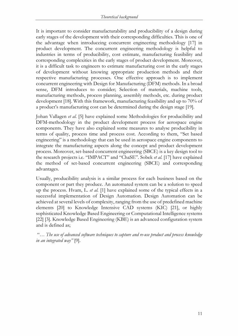
It is important to consider manufacturability and producibility of a design during early stages of the development with their corresponding difficulties. This is one of the advantage when introduceing concurrent engineering methodology [17] in product development. The concurrent engineering methodology is helpful to industries in terms of producibility, cost estimate, manufacturing feasibility and corresponding complexities in the early stages of product development. Moreover, it is a difficult task to engineers to estimate manufacturing cost in the early stages of development without knowing appropriate production methods and their respective manufacturing processes. One effective approach is to implement concurrent engineering with Design for Manufacturing (DFM) methods. In a broad sense, DFM introduces to consider; Selection of materials, machine tools, manufacturing methods, process planning, assembly methods, etc. during product development [18]. With this framework, manufacturing feasibility and up to 70% of a product’s manufacturing cost can be determined during the design stage [19].
Johan Vallagen et al. [5] have explained some Methodologies for producibility and DFM-methodology in the product development process for aerospace engine components. They have also explained some measures to analyse producibility in terms of quality, process time and process cost. According to them, “Set based engineering” is a methodology that can be used in aerospace engine components to integrate the manufacturing aspects along the concept and product development process. Moreover, set-based concurrent engineering (SBCE) is a key design tool to the research projects i.e. “IMPACT” and “ChaSE”. Sobek et al. [17] have explained the method of set-based concurrent engineering (SBCE) and corresponding advantages.
Usually, producibility analysis is a similar process for each business based on the component or part they produce. An automated system can be a solution to speed up the process. Hvam, L. et al. [1] have explained some of the typical effects in a successful implementation of Design Automation. Design Automation can be achieved at several levels of complexity, ranging from the use of predefined machine elements [20] to Knowledge Intensive CAD systems (KIC) [21], or highly sophisticated Knowledge Based Engineering or Computational Intelligence systems [22] [3]. Knowledge Based Engineering (KBE) is an advanced configuration system and is defined as;
“… The use of advanced software techniques to capture and re-use product and process knowledge in an integrated way” [9].

Theoretical background
12
Shukor, S. A. et al. [10] have described a Manufacturability analysis system and corresponding issues and future trends within their publications. Johan Vallhagen et al. [5] have explained an approach for producibility and DFM-methodology in an aerospace engine. During the work of Satyandra et al. [23], they have developed a Systematic method to evaluate the manufacturability from a CAD model in the early development stages. A CAD package object can be made with a set of input parameters. With that CAD system, a number of models can be developed by applying different input parameters. Similarly, the parameters can extract the information of a CAD to evaluate the model for the Manufacturability Assessment Systems (MAS) [10]. These extracted parameters can be evaluated by a set of “rules” of a producibility assessment system to know the manufacturing compatibility. Roberto Raffaeli et al. [24] has developed a solution which automatically identifies possible welds among the parts using prediction rules. These methods are to analyse the geometry and make cost estimates based on the shape, length and dimension of each weld.
For example, Yongjin Kwon et al. [25] have developed a CAD-based Decision Support System by using customized C++ codes to evaluate the geometric features of weld joints created under Pro/EngineerTM and Pro/WELDINGTM and address the critical problems in welding by DFM. There are some commercial softwares like “DFMPro” [26] (Advanced version of DFMXpress embedded in Solidworks) available to assess the manufacturability of a part from CAD model based on set of “Rules”. The analysis is mainly focusing on Machining, Casting, Sheet metal working, Injection Molding and Assembly. Weldability assessment is another requirement during manufacturability analysis. Process capability customisation is required for defining rules for a weldability analysis.
Certified industries often standardise their processes and procedures which are involved in their company operations. Data handbooks, working manuals, DP etc. are a few examples for those. With this documented analysis methods and the process technics a computerised automated system can be developed to evaluate the producibility and manufacturability of a design from the CAD model at early design stages [8].
There are some important terms to be considered while developing an adaptive type computerised automated systems. Elgh; F [27] has made an approach for documentation and knowledge management of systems for computerised automated system for ETO customised products. He emphasised the terms traceability, version control and system maintenance aspects for the automated ETO systems. Philip K. Mckinley et al. [28] have emphasised the term transparency and the importance of transparency in a software system to become adaptive to a changing environment. The term transparency has been defined by Pascal Meunier et al. [16] is;
“software transparency as a condition that all functions of software are disclosed to users”.

Theoretical background
13
2.1 Design Automation Systems The term design automation (DA) means an automation of well-defined engineering tasks [4]. The purpose of design automation is to reduce the time to do repetitive tasks. According to Blessing et al. [29], DA can be able to perform the specified design tasks either on their own or interactively with designers. To implement the design automation for a design process, both the knowledge and intelligence of those domains has to be taken into account.
Design Automation can be achieved at several levels of complexity, ranging from the use of predefined machine elements or family table/template systems (Siddique et al. [20]) to Knowledge Intensive CAD systems (KIC) Tomiyama et al. [21] or highly sophisticated Knowledge Based Engineering or Computational Intelligence systems (Sriram et al. [22]; Hoopgod et al. [3]).
Hannam et al. [30] have given an approach for manufacturability analysis i.e. design for producibility (DFP) with a Design automation system. Figure 2-2 describes the working procedure of design automation of a manufacturability analysis system. With the frame work of design requirements and manufacturing requirements, a manufacturing analysis can be done with an automation procedure.
Figure 2-2: Design automation in a DFP approach (Hannam et al. [30])
Computer aided analysis Experience Machines Process cost
data
Computer aided analysis
Market requirements
Research and development
Material availability Tooling
Design
Detail drawing Part listing
Product documentation with cost and lead-time
Estimations
Process plan Tool design
Operation sequence Jigs and fixtures NC preparation
Design requirement
and constraints
Manufacturing requirement
and constraints

Theoretical background
14
2.2 Knowledge based Engineering Systems Knowledge Based Engineering stands for, capturing the engineering knowledge and implementing this knowledge by a software tool for engineering process automation. It uses reasoning and semantics to emulate human thought and problem solving [31]. The basic difference between Design automation and Knowledge Based Engineering is that, design automation is an automation of well-defined sequential steps of a product development process to increase the process speed whereas the knowledge based engineering is an advanced level of design automation includes the methods of knowledge acquisition, modelling and management. Figure 2-3 shows a general application cycle of a knowledge based engineering technic. A typical knowledge based systems is comprised by the following system of elements [4]:
Knowledge Acquisition: Usually engineering knowledge exists in different forms. A method of capturing those forms of required and relevant engineering knowledge and transforming those into the knowledge base for storage and retrieval purpose.
Knowledge Base: Knowledge base is the storage of engineering knowledge, which includes the storage of domain knowledge and task knowledge. This knowledge base is an external unit to the working system. During the thesis, the term “Knowledge bank” has been used which is similar to Knowledge Base.
Case Specific Database: In some cases especially for big organisations the application of a KBE technic is suitable for many domains. So the database is divided into the particular domain application. This can be called as case specific database.
Inference Engine: The tool performs the problem solving process. It takes the knowledge from knowledge base or case specific database then computes and complete the problem solving process. A rule based (forward and backward chaining) [32], case-based and model-based reasoning, fuzzy logic, inductive technique are some examples for Inference techniques [33].
Explanation system: This is a subsystem for querying or searching the details of the inference engine and the case specific database. It is for the purpose of reasoning the details of the processes.
User Interface: The tool available to the user for specifying the problem details which are going to be solved, and receiving system outputs.

Theoretical background
15
Figure 2-3: knowledge based engineering application cycle
2.3 Multidisciplinary Analysis system In the previous sections, the term “Multidisciplinary Analysis system” was discussed. Before proceeding to the project execution, it is reasonable to understand the procedure of a Multidisciplinary Analysis system. The Multidisciplinary Analysis system is also called as “Engineering Workbench (EWB)” at GKN, internally. It is used to develop a specification/response model with a set of variables parameters. The purpose of this response model is to understand the product behaviour within a described design space. Figure 2-4 below describes the Multidisciplinary Analysis system working procedure.
Figure 2-4: Multidisciplinary Analysis system
1. Identify
2. Justify
3. Capture
4. Formalize
5. Process Package
6. Activate
Basic concept Parametric Model DoE Plan
Creation of Design cases
Analysis of each design cases Results Response Model
Theoretical background
16
Basic concept
The Multidisciplinary Analysis system begins with the baseline concept or basic idea of the required design. This could be either a customer requirement or a new design idea.
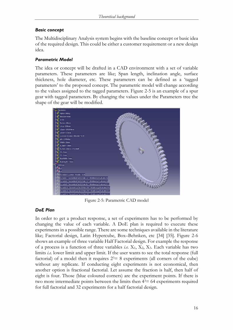
Parametric Model
The idea or concept will be drafted in a CAD environment with a set of variable parameters. These parameters are like; Span length, inclination angle, surface thickness, hole diameter, etc. These parameters can be defined as a ‘tagged parameters’ to the proposed concept. The parametric model will change according to the values assigned to the tagged parameters. Figure 2-5 is an example of a spur gear with tagged parameters. By changing the values under the Parameters tree the shape of the gear will be modified.
Figure 2-5: Parametric CAD model
DoE Plan
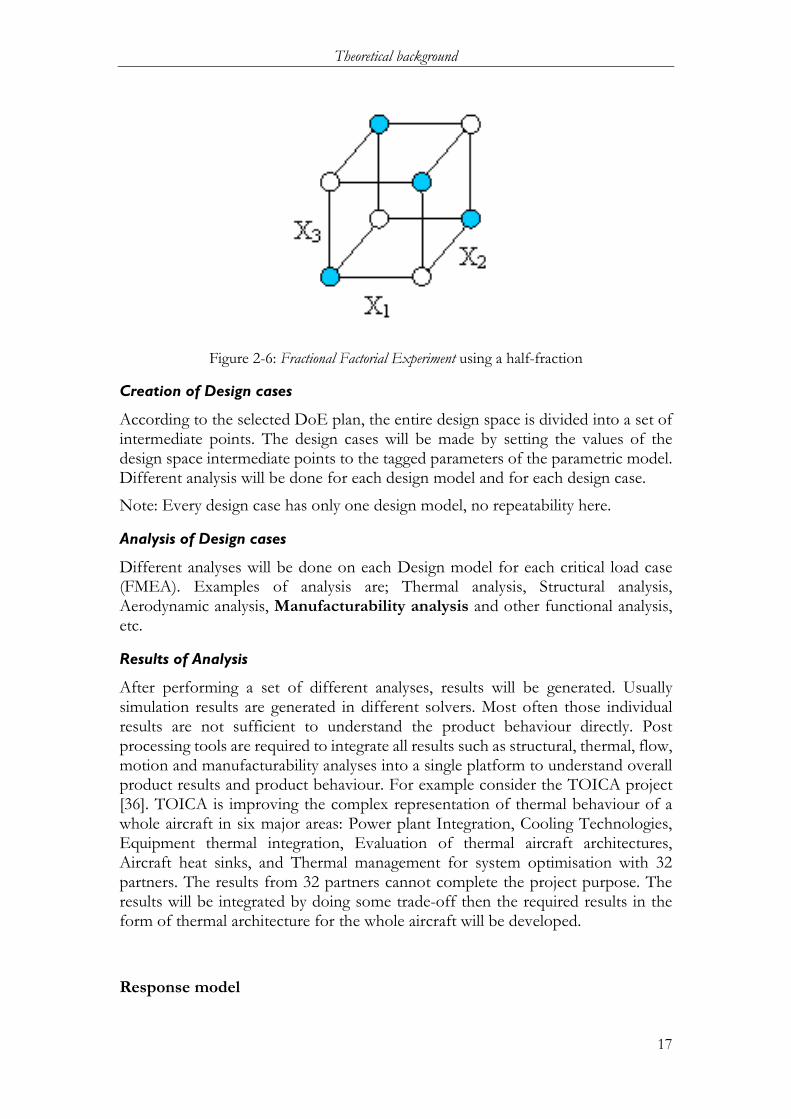
In order to get a product response, a set of experiments has to be performed by changing the value of each variable. A DoE plan is required to execute these experiments in a possible range. There are some techniques available in the literature like; Factorial design, Latin Hypercube, Box–Behnken, etc [34] [35]. Figure 2-6 shows an example of three variable Half Factorial design. For example the response of a process is a function of three variables i.e. X1, X2, X3. Each variable has two limits i.e. lower limit and upper limit. If the user wants to see the total response (full factorial) of a model then it requires 23= 8 experiments (all corners of the cube) without any replicate. If conducting eight experiments is not economical, then another option is fractional factorial. Let assume the fraction is half, then half of eight is four. Those (blue coloured corners) are the experiment points. If there is two more intermediate points between the limits then 43= 64 experiments required for full factorial and 32 experiments for a half factorial design.
Theoretical background
17
Figure 2-6: Fractional Factorial Experiment using a half-fraction
Creation of Design cases
According to the selected DoE plan, the entire design space is divided into a set of intermediate points. The design cases will be made by setting the values of the design space intermediate points to the tagged parameters of the parametric model. Different analysis will be done for each design model and for each design case.
Note: Every design case has only one design model, no repeatability here.
Analysis of Design cases
Different analyses will be done on each Design model for each critical load case (FMEA). Examples of analysis are; Thermal analysis, Structural analysis, Aerodynamic analysis, Manufacturability analysis and other functional analysis, etc.
Results of Analysis
After performing a set of different analyses, results will be generated. Usually simulation results are generated in different solvers. Most often those individual results are not sufficient to understand the product behaviour directly. Post processing tools are required to integrate all results such as structural, thermal, flow, motion and manufacturability analyses into a single platform to understand overall product results and product behaviour. For example consider the TOICA project [36]. TOICA is improving the complex representation of thermal behaviour of a whole aircraft in six major areas: Power plant Integration, Cooling Technologies, Equipment thermal integration, Evaluation of thermal aircraft architectures, Aircraft heat sinks, and Thermal management for system optimisation with 32 partners. The results from 32 partners cannot complete the project purpose. The results will be integrated by doing some trade-off then the required results in the form of thermal architecture for the whole aircraft will be developed.
Response model
Theoretical background
18
Making a response model is a post processing of results. There are some technics available in the literature like; regression technique, graphical model, etc. The response model is used to understand product behaviour under normal working conditions in a defend design space.
The specified steps in the Multidisciplinary Analysis are done automatically with an automated system. Manufacturability analysis is a part of multidisciplinary analysis, which was explained in section 2.3 During the Manufacturability analysis, component Producibility will be verified in terms of weldability and other manufacturing process. The Weldability Analysis is to investigate weld possibilities to the proposed design with the company’s infrastructure, technological competencies, available welding processes, company’s best practices and etc.
2.4 Manufacturability Assessment Systems Manufacturability Assessment Systems (MAS) is a system which was developed to analyse the manufacturability aspects of the proposed design in early stages of design and development. Before moving the details of MAS, it is good to know the meaning of the terms producibility and manufacturability.
The terms have many definitions from different researchers. Among them the following definitions are relevant to the selected thesis work, the producibility can be defined as Johan Vallhagen el al [5]:
“... the capability to produce the product in a robust and efficient way to meet the design specifications for functions and reliability of the product”
And the manufacturability can be defined as in terms of Satyandra K Gupta et al. [23]:
“… evaluating the manufacturability of a proposed design involves determining whether or not it is manufacturable with a given set of manufacturing operations, and, if it is, finding the associated manufacturing efficiency”
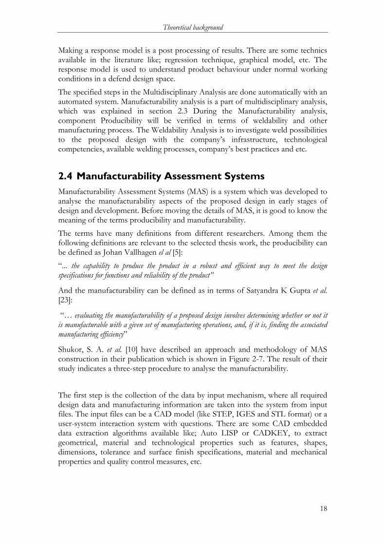
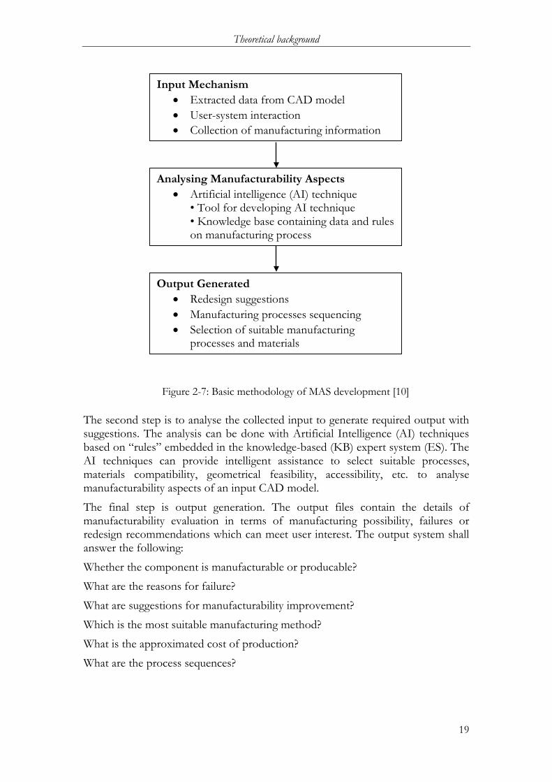
Shukor, S. A. et al. [10] have described an approach and methodology of MAS construction in their publication which is shown in Figure 2-7. The result of their study indicates a three-step procedure to analyse the manufacturability.
The first step is the collection of the data by input mechanism, where all required design data and manufacturing information are taken into the system from input files. The input files can be a CAD model (like STEP, IGES and STL format) or a user-system interaction system with questions. There are some CAD embedded data extraction algorithms available like; Auto LISP or CADKEY, to extract geometrical, material and technological properties such as features, shapes, dimensions, tolerance and surface finish specifications, material and mechanical properties and quality control measures, etc.
Theoretical background
19
The second step is to analyse the collected input to generate required output with suggestions. The analysis can be done with Artificial Intelligence (AI) techniques based on “rules” embedded in the knowledge-based (KB) expert system (ES). The AI techniques can provide intelligent assistance to select suitable processes, materials compatibility, geometrical feasibility, accessibility, etc. to analyse manufacturability aspects of an input CAD model.
The final step is output generation. The output files contain the details of manufacturability evaluation in terms of manufacturing possibility, failures or redesign recommendations which can meet user interest. The output system shall answer the following:
Whether the component is manufacturable or producable?
What are the reasons for failure?
What are suggestions for manufacturability improvement?
Which is the most suitable manufacturing method?
What is the approximated cost of production?
What are the process sequences?
Input Mechanism • Extracted data from CAD model • User-system interaction • Collection of manufacturing information
Analysing Manufacturability Aspects • Artificial intelligence (AI) technique
• Tool for developing AI technique • Knowledge base containing data and rules on manufacturing process
Output Generated • Redesign suggestions • Manufacturing processes sequencing • Selection of suitable manufacturing
processes and materials
Figure 2-7: Basic methodology of MAS development [10]
Theoretical background
20
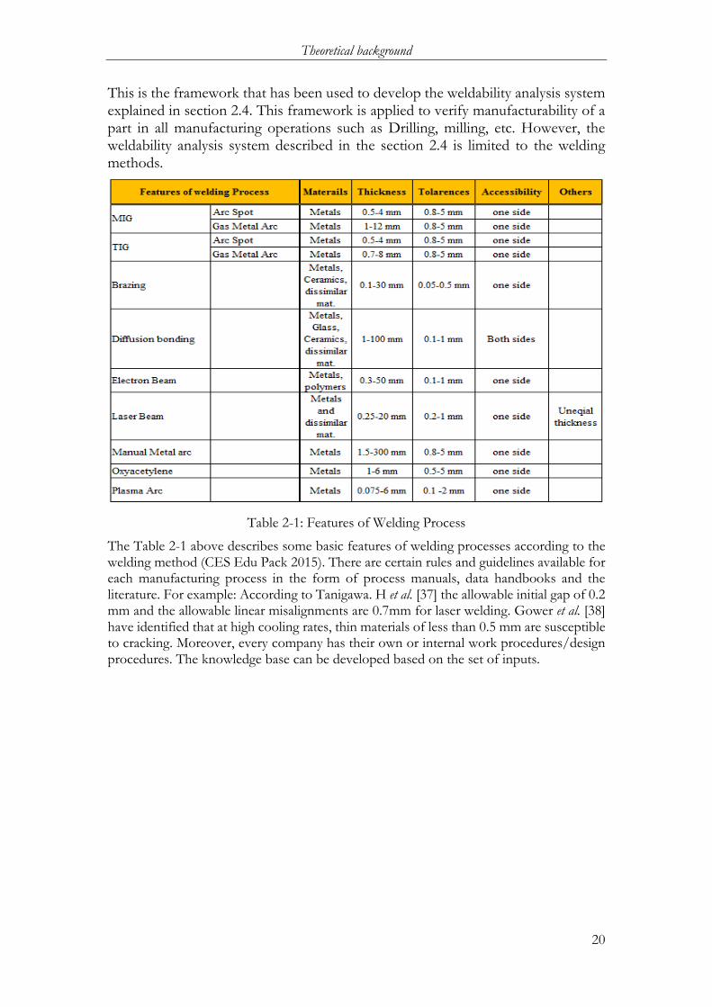
This is the framework that has been used to develop the weldability analysis system explained in section 2.4. This framework is applied to verify manufacturability of a part in all manufacturing operations such as Drilling, milling, etc. However, the weldability analysis system described in the section 2.4 is limited to the welding methods.
Table 2-1: Features of Welding Process
The Table 2-1 above describes some basic features of welding processes according to the welding method (CES Edu Pack 2015). There are certain rules and guidelines available for each manufacturing process in the form of process manuals, data handbooks and the literature. For example: According to Tanigawa. H et al. [37] the allowable initial gap of 0.2 mm and the allowable linear misalignments are 0.7mm for laser welding. Gower et al. [38] have identified that at high cooling rates, thin materials of less than 0.5 mm are susceptible to cracking. Moreover, every company has their own or internal work procedures/design procedures. The knowledge base can be developed based on the set of inputs.

Methods and Implementation
21
3 Methods and implementation ************************************************************************** The Methods and Implementation chapter describes the possible methods and their suitability to the selected thesis. The application of a selected research method and project implementation steps have been explained in the later part.
**************************************************************************
The core objective to this thesis project is to make contribution to the research projects i.e. “IMPACT” in terms of Transparency and Maintainability of an automated analysis system. The method of implementation for this research project is based on the Design Research Methodology by Blessing et al. [29], which is explained briefly in the section 3.1. The primary intention is to consider the same approach to the proposed thesis basis on feasibility. The feasibility study is based on the purpose of the thesis, time frame and available tools and technics and also the author’s knowledge about the thesis topic.
3.1 Design Research Methodology (DRM) Blessing et al. [29] developed a DRM research model and state that design research is a multidisciplinary and aims for both understanding the phenomenon of design then using this understanding to change the way the design process is carried out. The method begins with basic questions like; what do we mean by a Successful and criteria to define successfulness? Then, how can we reach success? And how do we improve the chances of being successful?
In order to perform research based on this method, there must be a requirement for a proper validation method. Figure 3-1 below shows the DRM framework with deliverables of four main action steps in this research methodology. The four main action steps in this research methodology are described below according to the thesis suitability.
Research clarification Research clarification contains Identification of main goals, Criteria for success and Measurable for success criteria in a given situation. This is where the focus of the research is identified.
The research purpose has been defined in the section 1.4 with a research question. Introduction of transparency, recognisability, traceability, and upgradability into the DFM-weldability analysis system is the main purpose of the research. In fact, the research clarification is not complete with finding the research purpose. The purpose of the research must be identified in terms of application of the DFM-weldability analysis system under the scientific point of view; process, procedure, applications, exact users, user needs and expectations and so on. As described in the background section, GKN aerospace, Sweden is also working on the development of knowledge based applications for engineering ETO purposes. So GKN could be a potential user to use the DFM-weldability analysis system. Apart from the scientific literature study, inputs can be taken from GKN to refine the thesis goals according to the user perspective.
Methods and Implementation
22
Based on the research purpose success criteria must be developed. The developed success criteria are supporting the researcher to focus on the research aim, finding the influence factors trough the descriptive study, address those factors in the prescriptive study to improve the situation and finally to validate the findings.
The research clarification part can be completed with a set of deliverables. The deliverables include initial reference model (Figure 2-7), an impact model (Figure 3-3) to guide the research to meet the success criteria, development of preliminary success criteria and overall thesis execution plan.
Descriptive Study I Descriptive studies involve observation and analysis of the given situation, in order to provide an understanding of factors that directly or indirectly influence the main criterion/criteria for success.
After understanding the thesis’s purpose and thesis’s aim, a study needs to be done for understanding the problems and situation of existing Weldability evaluation methods. Through that study, the influencing factors need to be identified to improve the Transparency, Recognisability, Traceability, and upgradability of the DFM-Weldability analysis system. The Initial reference model will be improved with the influencing factors.
Based on the descriptive study, the influencing factors will be identified, the assumed success criteria in the research clarification phase will be reformulated or corrected if required. A new improved reference model will be proposed to perform the prescriptive study. The improved reference model will address the current problems and the limitations to meet the success criteria. Measurables will be defined to the updated success criteria to evaluate the success.
Prescriptive Study
Based on the descriptive study, a method or tool is developed in order to improve the situation.
During the prescriptive study the reference model will be developed as a prototype i.e. Impact model. The Impact model must be capable to resolve the problems and current limitations which were defined in the descriptive study. This Impact model also addresses those influencing factors addressed in the descriptive study. An evaluation plan will be made to evaluate the developed model according to the defined success criteria.
Descriptive Study II A method or tool is applied and a descriptive study is carried out in order to validate the method or tool. Also addresses whether the situation is supported in comparison with the purpose of study.
During the second descriptive study, the model developed in the prescriptive study will be evaluated according to the evaluation plan. The evaluation measures will be compared with the success criteria then implications will be noted. Based on the result’s satisfactory level towards the Transparency, Recognisability, Traceability, and upgradability a new design cycle will be planned.

Methods and Implementation
23
Figure 3-1: DRM frame work [29]
Feasibility study: A typical Design Research is a construction and evaluation of technology artefacts to meet organisational goals [39] where principles are changes through learning. The learning efforts are higher than the implementation efforts. DRM suits for the development of new novel technology to develop an innovative impact model. Since the selected thesis is an extension part of another thesis, the problems and the influencing factors are not fully anonymous. The purpose and the thesis background was investigated during the thesis selection. The success is more likely with the application of existing tools and technics rather doing research to find new exclusive ways. The thesis interest is to find a safe solution with existing technology. Moreover, the research study is part of the master program with definite time. By considering these things, “Action research” can be used for the thesis work. The details of the action research methodology and the project application is explained in the following section 3.2.
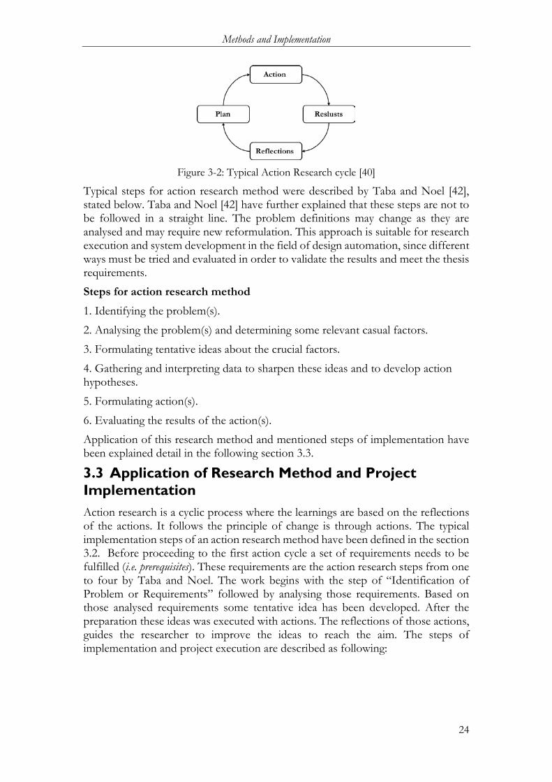
3.2 Action Research Action research is a methodology, which is concerned with knowledge and improvement by human action [40]. According to Frayling et al. [41], it is subset of research through art and design usually done in discrete cycles. A typical action research cycle has been shown in Figure 3-2. The action research is reflective, which is required to verify whether the current action does produce actual results or change is needed where the reflections are based on trials of actions which are based on the analysis of the results of previous action in order to prescribe new and refined actions.
Methods and Implementation
24
Figure 3-2: Typical Action Research cycle [40]
Typical steps for action research method were described by Taba and Noel [42], stated below. Taba and Noel [42] have further explained that these steps are not to be followed in a straight line. The problem definitions may change as they are analysed and may require new reformulation. This approach is suitable for research execution and system development in the field of design automation, since different ways must be tried and evaluated in order to validate the results and meet the thesis requirements.
Steps for action research method 1. Identifying the problem(s).
2. Analysing the problem(s) and determining some relevant casual factors.
3. Formulating tentative ideas about the crucial factors.
4. Gathering and interpreting data to sharpen these ideas and to develop action hypotheses.
5. Formulating action(s).
6. Evaluating the results of the action(s).
Application of this research method and mentioned steps of implementation have been explained detail in the following section 3.3.
3.3 Application of Research Method and Project Implementation Action research is a cyclic process where the learnings are based on the reflections of the actions. It follows the principle of change is through actions. The typical implementation steps of an action research method have been defined in the section 3.2. Before proceeding to the first action cycle a set of requirements needs to be fulfilled (i.e. prerequisites). These requirements are the action research steps from one to four by Taba and Noel. The work begins with the step of “Identification of Problem or Requirements” followed by analysing those requirements. Based on those analysed requirements some tentative idea has been developed. After the preparation these ideas was executed with actions. The reflections of those actions, guides the researcher to improve the ideas to reach the aim. The steps of implementation and project execution are described as following:

Methods and Implementation
25
3.3.1 Identification of requirement:
As stated earlier, the purpose of this thesis project is to address the maintainability aspects such as Transparency, Recognisability, Traceability, and upgradability into the automated DFM-Weldability analysis system. Apart from this, there are some other requirements according to the application perspective. Those are; the proposed system must be compatible to the existing Industrial environment such as; software availability, General Software knowledge and the most important requirement is that defined technics must be suitable for the company in the long-run. Consenting to these requirements, there was a visit on 4th of September to the GKN Aerospace, located at Trollhättan, Sweden. Some feedback has been taken from Mr. Petter Andersson. Mr. Petter Andersson is a working employee in the company working on Knowledge modelling and KBE Methods for the product development. Those requirements are summarised as below:
• The evaluation model must be capable to evaluate all joints of a component in the CAD model. (usually more than one)
• The output of the weld analysis for all joints must be summarised in a single sheet
• The evaluation model must be suitable to the user to investigate evaluation results with corresponding details
• The Evaluation results must be in a form such that everyone can understand easily. For example; OK or Not OK, Yes or No, Go or No-go, etc.
• Desire to include a “warning” message with evaluation results
• References need to be included in the evaluation results
• The Knowledge and the execution must be separated
• Each data sheet must be managed with version details
• The system must be capable to fit in the PLM/ PDM standards
• The Knowledge data sheets must be upgradable
• All the updates and the changes must be traceable
• The execution must be transparent to the end user
• The execution process must be recognisable to the user The work has been started with these set of requirements and the implementation status has been discussed in the section 5.2.5.
3.3.2 Analysing the requirements and determining some relevant factors
The purpose of this part is to convert the list of requirements from the user-voice to the engineer’s-voice. In the following paragraph the requirements have been analysed and converted into engineering requirements.
Methods and Implementation
26
From the list of requirements it is understandable that there is a need for a weldability analysis system. This system must be capable to analyse the weldability of a part from its CAD model. This CAD model will be the INPUT to the system. The system must be capable to evaluate all joints of that part. The evaluation results will be the OUTPUT of that system. It is desired that the output must be ‘summarised’ and ‘easy to understand’ to the user, probably in OK or NOT OK form. The evaluation must be based on a set of instructions and weld methods capabilities. These instructions and the weld-methods capabilities must be kept separate with the execution mechanism and will be easy to maintain in the long-term by the company. Moreover the entire working systems must be maintainable in the long-run in terms of Transparency, Recognisability, Traceability, and upgradability.
The above analysis can be further summarised as follows; a computerised automated weldability analysis system is required. This system must have three parts. Those are INPUT, ANALYSIS and OUTPUT. A CAD model will be the INPUT. The ANALYSIS system has to work with a set of instructions while weld method knowledge and the result’s summary shall be its OUTPUT. And it is crucial that the entire system is maintainable in the long-run in terms of Transparency, Recognisability, Traceability, and upgradability.
3.3.3 Formulating tentative ideas for execution
After analysing the requirements it is understood that an automated weldability analysis system with INPUT, ANALYSIS and OUTPUT is required. The manufacturability analysis system (MAS) with Input, Analysis and Output is available in the literature and explained in section 2.4. The application of this method is suitable for this thesis work. The Input part could be the CAD model with the weld joints (usually more than one) and the details of the joint information. The Analysis part is for evaluation of the weldability. It could be done on the basis of knowledge data with a set of instructions i.e. artificial intelligence (AI). Available weld-methods and their capabilities are the knowledge data sometimes also referred as ‘Knowledge bank’. The output part could be a summary of evaluation results with simplified “Yes” or “No” answers with references. The implementation of MAS for the weldability analysis is named as “Weldability Analysis System”.
Methods and Implementation
27
Weldability Analysis system
A Weldability analysis system is a system to verify the weldability of a joint by considering a number of existing welding methods. Figure 3-3 shows the schematic representation of a weldability analysis procedure. The analysis system has three parts i.e. Input, Analysis and Output. The Input part comes in the form of a CAD model with joint information, the analysis part is to analyse the joint in terms of weldability and gives the results, while the output part is to process the results and generate the summary. The summary will include the feasible weld method, reasons for failure, improvement suggestions, welding process plan and finally cost of welding.
Input The joint information will be the input to the analysis system. This information will be extracted from the 3D- CAD model. Material, type of weld, weld thickness, weld length, weld curvature, reachability angle, reachability distance and etc. are the basic weld information for a joint. This information can be extracted from the CAD model at an early design stage and possibility to tag this information to the parameters in a CATIA working environment. For the purpose of this thesis project, this tagging has been done manually but it can be programed with a CATIA VBA or similar CAD programming applications.
There are some ways available in the literature to extract the joint information from CAD model for example feature recognition technic and etc. But those technics has certain limitations too because these techniques are subjected to individual’s logic and possible to differ from one organisation to another.
Analysis
The analysis part is to evaluate the weldability of a part. The analysis part is subdivided into three parts i.e. Knowledge, Intelligence and Execution. The details of the weld methods, values and process constraints are sub components of knowledge. Lists of material or material combinations suitable to laser beam welding and the maximum weld thickness which can be achieved by the TIG weld method are some examples of knowledge. A set of rules, which describes whether the joint is weldable or not are example of Intelligence. The intelligence defines the weldability by considering different aspects. Before saying ‘the joint is weldable with selected weld method’ the joint material must be verified with weld possibilities with the chosen welding method. This is one of the rule in the intelligence system which is saying that while analysing the weld joint with a weld method material suitability must be verified. The rules used in this thesis work have been extracted from literature, Process manuals, Hand books, company best practices (which are available on the web) and others. The third part of an analysis system is Execution. It is an inference engine which can take the inputs, then verify those inputs with each rule of the Intelligence with available knowledge and then give results to the output system.

Methods and Implementation
28
Output The output part is to reflect the analysed results in a summarised form. After the analysis, the results are in the form of data which is transferred to the output system. The output system will process these data and gives a summary of results. The joints will be listed as weldable or not weldable, including the reasons for non-weldability and how it can be improved. It also produces a sequence plan for welding of all joints of a component and the possible cost for the weld. A summary of these results will be made at the end of the output.
Figure 3-3: Weldability Analysis System
Since the system of evaluation must be easy to understand to the end user and compatible to the existing Industrial environment, MS-Excel could be a good option, because most of the industries use MS-office. Moreover, most of the people understand MS-Excel’s logical relations and connections. The Knowledge data is also possible to be stored and interpreted in MS-Excel in different forms like; Numeric, alphabetical and Alphanumeric and PIVOT-tables. Macros will be helpful for sub arguments.
The knowledge can be created for each weld method separately with the process constraints and limitations. And this knowledge can be easily updated according to the technology updates and company’s competencies. Regarding to AI System, an MS-Excel type “Rule base” system can be a suitable idea to evaluate the Input data. Because MS-Excel can interpret the data with a set of logical relations (‘>’, ‘<’ and ‘=’) easily. The rules can be made from Scientific Knowledge i.e. Literature, Operation Manuals, Handbooks, Company’s Design practices and Industrial best practices. These rules can be made one time in the individual MS-Excel sheet and updated or amended on need basis, with various versions. These data files are also possible to be managed by PLM/PDM system.
3D Geometric Model
Rules for Manufacturability
Analysis Weld methods
and Details
Details of Weld from CAD model
Manufacturing Cost Estimation
Selection of feasible weld
method
Suggestions for manufacturability
Improvements
Analysis software
Process Sequence /
Production Plan
Output
Input
Analysis

Methods and Implementation
29
Regarding Input & Output Mechanism, the joint details with a joint name can be tagged to the CATIA Parameters; these parameters can be imported to the MS-Excel document as an input. Once the weldability evaluation has been done, the results can be stored in the output sheets (i.e.MS-Excel) with connections.
Considering the execution, either MS-Excel worksheets with VBA modules can be used for execution. Or else, the software “Howtomation” package has an option to transfer data from one working medium to another working medium with “Knowledge objectives” and “Parameters”. The working description of “Howtomation” software has been discussed in section 3.3.5. The application of “Howtomation” software is discussed in the action cycles part i.e. section 3.3.5.
3.3.4 Gathering and interpreting data to make first action plan
In order to start the action cycles, a set of things must be prepared. This is made of a CAD model with parameters, which are tagged with joint details. Making a set of Rules is to execute the weldability. Create a knowledge base for different weld processes, Making of data connection logic and Make an output summary file. According to the principle of Manufacturability assessment system, the requirement system can be divided into five parts
1. Creation of Parameters in the CAD model and tag the joint details to that
2. Preparation of rules and their execution plan
3. Making of Manufacturing knowledge base
4. Creation of execution system
5. System for output and summary
Once the weldability analysis system has been created, the maintainability attributes such as transparency, recognisability, tractability and upgradability considerations will be introduced and verified in order to complete the first action cycle.
Figure 3-4: Parameters to the CAD model
Creation of Parameters in the CAD model
Methods and Implementation
30
After making the solid model of the component in the CAD system, the parameters of each weld joint must to be created. The TRS model has been created in the CATIA environment for the thesis purpose instead of Siemens NXTM environment using by GKN. The selection of working medium is subjected to availability and the working knowledge. The CATIA parameters have been created and weld details have been tagged to these parameters Figure 3-4. Preparation of rules and their execution plan
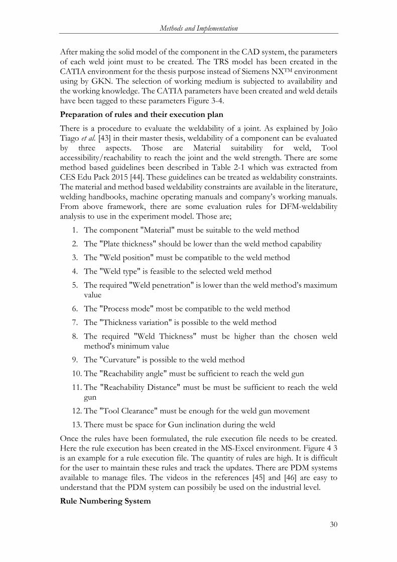
There is a procedure to evaluate the weldability of a joint. As explained by João Tiago et al. [43] in their master thesis, weldability of a component can be evaluated by three aspects. Those are Material suitability for weld, Tool accessibility/reachability to reach the joint and the weld strength. There are some method based guidelines been described in Table 2-1 which was extracted from CES Edu Pack 2015 [44]. These guidelines can be treated as weldability constraints. The material and method based weldability constraints are available in the literature, welding handbooks, machine operating manuals and company’s working manuals. From above framework, there are some evaluation rules for DFM-weldability analysis to use in the experiment model. Those are;
1. The component "Material" must be suitable to the weld method
2. The "Plate thickness" should be lower than the weld method capability
3. The "Weld position" must be compatible to the weld method
4. The "Weld type" is feasible to the selected weld method
5. The required "Weld penetration" is lower than the weld method’s maximum value
6. The "Process mode" most be compatible to the weld method
7. The "Thickness variation" is possible to the weld method
8. The required "Weld Thickness" must be higher than the chosen weld method's minimum value
9. The "Curvature" is possible to the weld method
10. The "Reachability angle" must be sufficient to reach the weld gun
11. The "Reachability Distance" must be must be sufficient to reach the weld gun
12. The "Tool Clearance" must be enough for the weld gun movement
13. There must be space for Gun inclination during the weld
Once the rules have been formulated, the rule execution file needs to be created. Here the rule execution has been created in the MS-Excel environment. Figure 4 3 is an example for a rule execution file. The quantity of rules are high. It is difficult for the user to maintain these rules and track the updates. There are PDM systems available to manage files. The videos in the references [45] and [46] are easy to understand that the PDM system can possibily be used on the industrial level.
Rule Numbering System
Methods and Implementation
31
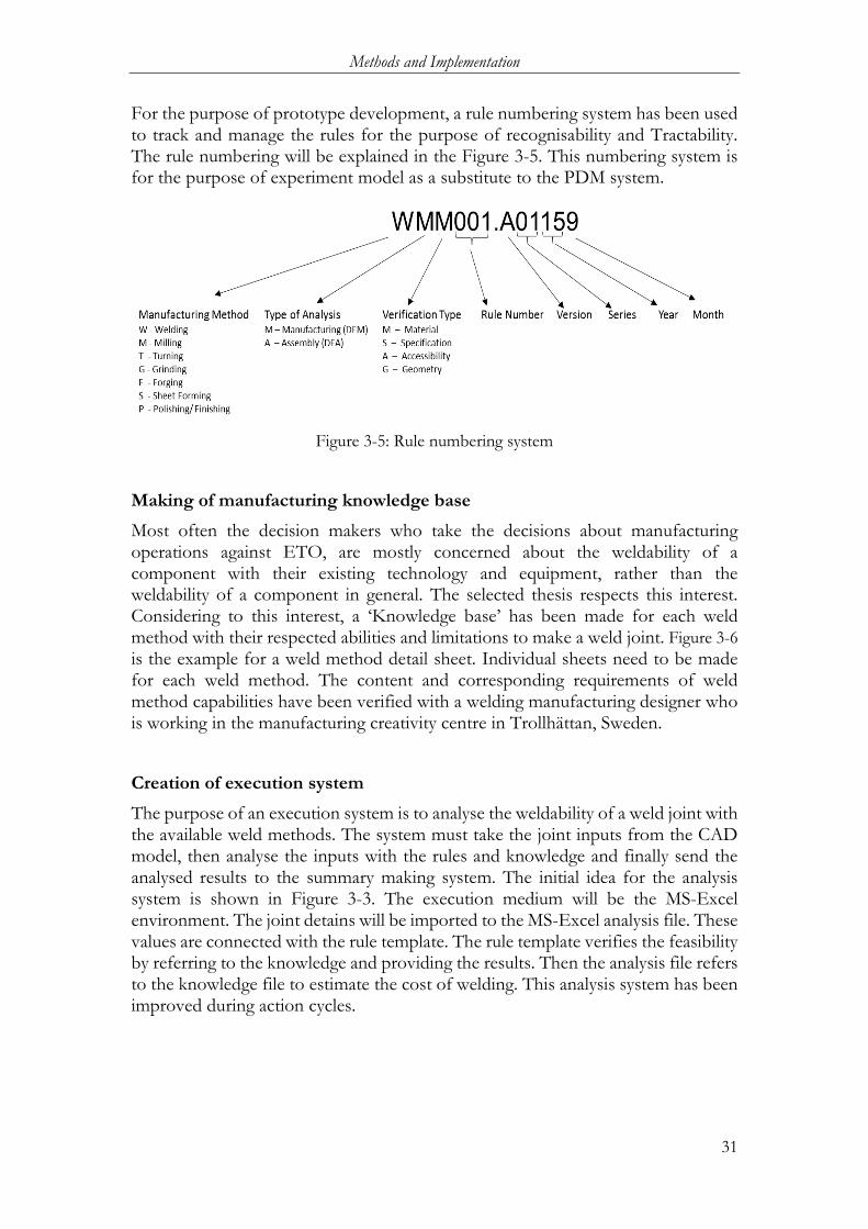
For the purpose of prototype development, a rule numbering system has been used to track and manage the rules for the purpose of recognisability and Tractability. The rule numbering will be explained in the Figure 3-5. This numbering system is for the purpose of experiment model as a substitute to the PDM system.
Figure 3-5: Rule numbering system
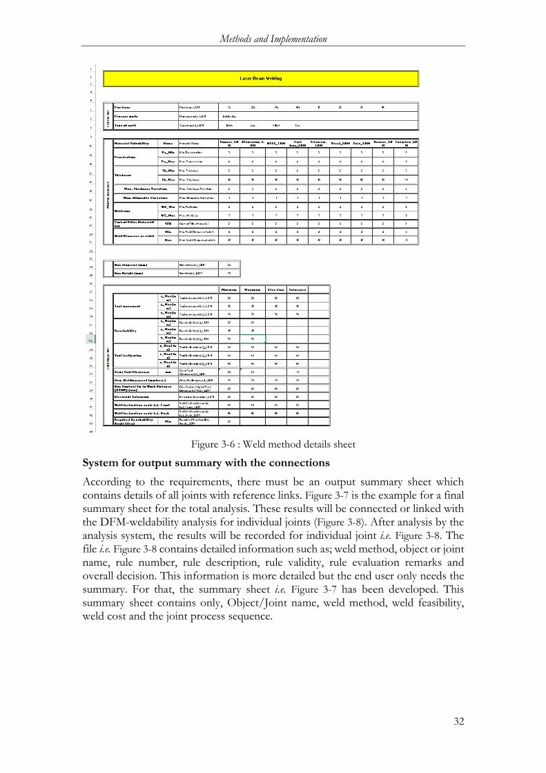
Making of manufacturing knowledge base Most often the decision makers who take the decisions about manufacturing operations against ETO, are mostly concerned about the weldability of a component with their existing technology and equipment, rather than the weldability of a component in general. The selected thesis respects this interest. Considering to this interest, a ‘Knowledge base’ has been made for each weld method with their respected abilities and limitations to make a weld joint. Figure 3-6 is the example for a weld method detail sheet. Individual sheets need to be made for each weld method. The content and corresponding requirements of weld method capabilities have been verified with a welding manufacturing designer who is working in the manufacturing creativity centre in Trollhättan, Sweden.
Creation of execution system The purpose of an execution system is to analyse the weldability of a weld joint with the available weld methods. The system must take the joint inputs from the CAD model, then analyse the inputs with the rules and knowledge and finally send the analysed results to the summary making system. The initial idea for the analysis system is shown in Figure 3-3. The execution medium will be the MS-Excel environment. The joint detains will be imported to the MS-Excel analysis file. These values are connected with the rule template. The rule template verifies the feasibility by referring to the knowledge and providing the results. Then the analysis file refers to the knowledge file to estimate the cost of welding. This analysis system has been improved during action cycles.
Methods and Implementation
32
Figure 3-6 : Weld method details sheet
System for output summary with the connections According to the requirements, there must be an output summary sheet which contains details of all joints with reference links. Figure 3-7 is the example for a final summary sheet for the total analysis. These results will be connected or linked with the DFM-weldability analysis for individual joints (Figure 3-8). After analysis by the analysis system, the results will be recorded for individual joint i.e. Figure 3-8. The file i.e. Figure 3-8 contains detailed information such as; weld method, object or joint name, rule number, rule description, rule validity, rule evaluation remarks and overall decision. This information is more detailed but the end user only needs the summary. For that, the summary sheet i.e. Figure 3-7 has been developed. This summary sheet contains only, Object/Joint name, weld method, weld feasibility, weld cost and the joint process sequence.

Methods and Implementation
33
Figure 3-7: DFM-Weldability analysis summary sheet
Figure 3-8: DFM-Weldability analysis for individual joint
3.3.5 Action Cycles for Software development
The experimental model has been developed in several action cycles. As explained in Figure 3-2, the action cycle begins with a logical idea to analyse the Weldability of a component. Then the action has been performed in the form of software coding or programming to build a prototype model. Then this model has been tested in terms of meeting the requirements such as Transparency, Recognisability, Traceability, upgradability and other maintainability aspects. The reflection has been taken from the test results and has then been evaluated with the purpose of the thesis. The new or modified logics have been prepared based on these reflections in order to overcome the limitations of the previous logic. There are different logics been made during the prototype model development. It is difficult to document each. Some improvement steps during the development are described below:
Methods and Implementation
34
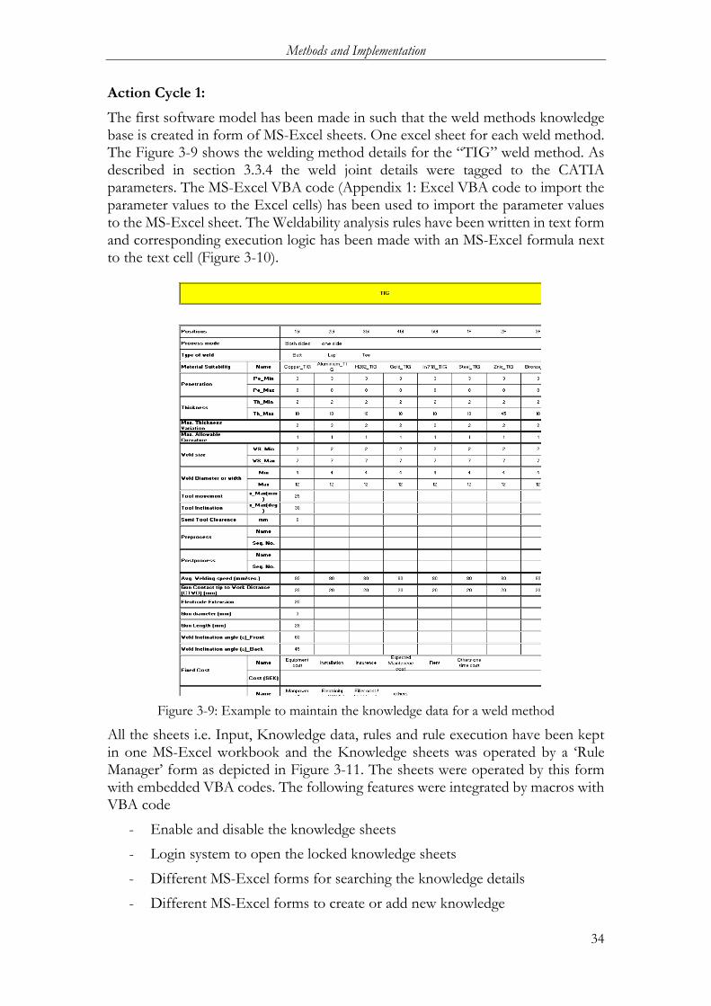
Action Cycle 1: The first software model has been made in such that the weld methods knowledge base is created in form of MS-Excel sheets. One excel sheet for each weld method. The Figure 3-9 shows the welding method details for the “TIG” weld method. As described in section 3.3.4 the weld joint details were tagged to the CATIA parameters. The MS-Excel VBA code (Appendix 1: Excel VBA code to import the parameter values to the Excel cells) has been used to import the parameter values to the MS-Excel sheet. The Weldability analysis rules have been written in text form and corresponding execution logic has been made with an MS-Excel formula next to the text cell (Figure 3-10).
Figure 3-9: Example to maintain the knowledge data for a weld method
All the sheets i.e. Input, Knowledge data, rules and rule execution have been kept in one MS-Excel workbook and the Knowledge sheets was operated by a ‘Rule Manager’ form as depicted in Figure 3-11. The sheets were operated by this form with embedded VBA codes. The following features were integrated by macros with VBA code
- Enable and disable the knowledge sheets
- Login system to open the locked knowledge sheets
- Different MS-Excel forms for searching the knowledge details
- Different MS-Excel forms to create or add new knowledge

Methods and Implementation
35
This idea has limitations in many aspects. One of the stated requirements is that all the sheets must be in an individual file. But in this method, all the sheets are in a single workbook. Transparency; since all the rules and knowledge is in a single workbook connected with MS-Excel links, the method was transparent enough. Recognisability; since all evaluations are performed in a single worksheet cell with a long formula, the recognisability was difficult for the end user. Tractability; the only way to trace the rule details was a rule number. However, there was no rule modification history. Upgradability; This method is upgradable, but the user has to make long efforts to upgrade the rules with additions and deletions and the addition of one weld method in the knowledge leads to modification of all rules’ execution formula for this addition and deletion. For instance, if there are twenty rules and three versions, then the user has to update the formula in sixty cells. Moreover, it is not transparent that the formulas have been updated, which may be not comfortable for the end user.
Figure 3-10: Rule Execution sheet
Figure 3-11 : Rule Manager Form
Action Cycle 2:

Methods and Implementation
36
In the second action cycle, the above limitations had been considered to improve the system. The first change was, all the sheets in the workbook such as rules bank, rule execution with summary and weld methods were separated from the single workbook to the different MS-Excel workbooks. All the rules have been written in a single work book and the rule execution has been done with Macros Module. Functions have been written for each rule for each weld method. The example code is in the Appendix 2: Excel VBA Functions to execute the rule. This code i.e. Appendix 2: Excel VBA Functions to execute the rule serves as an example to evaluate the material suitability for the Laser beam weld method (first part) and “TIG” (second part). These functions will be utilized during the Weldability analysis of a joint. The functions will be created as VBA modules and these modules will be called or referred with the following command. Application.Run "'[workbook name]'!" [Module name].[function name]"
Functions need to be written for the each rule and each weld methods. The rules will be added and removed to the “Rule Bank” file. To analyze the weldability of a joint, the user has to select the required rules from the rule bank and then this selection will be reflected in the Execution file (Figure 3-10). The joint parameters will be imported by clicking the “Import” button and the weld joint evaluation will executed after clicking the “Command button” above the rules.
In this method of logic the Knowledge, Intelligence and the Execution have been separated. The intelligence (Rules) and Knowledge is upgradable. Apart from this, there are some limitation to this method in terms of Transparency; since the execution has been written in MS-Excel VBA code which is hidden to the end user. Recognisability; The VBA code logic is subjected to an individual and may be difficult to understand for others. There are a lot of comments to be written in the code to recognise the method logic. Another big disadvantage is that the user has to write several functions for an introduction of a new weld method. If there are 20 rules existing in the current situation then the end user has to write 20 functions for each addition and deletion of weld method which is a difficult job for the end user.
Action Cycle 3: In order to eliminate the problems in the second action cycle. The software called “Howtomation” has been introduced to evaluate the Weldability of a joint.
“Howtomation” is a communication software based on a ‘.net’ application. It is developed by Mr. Joel Johansson, an Assistant Professor in the Department of Product development, School of Engineering, Jönköping University. The software has an unique feature that it can transfer the information from one working medium to another working medium such as; CATIA , MS-Excel, Math CAD and Soldworks environment, by using ‘Knowledge objects’ and ‘Parameters’. Figure 3-12 below is the picture of the user interface. The yellow box item is the knowledge objects and the oval item is a Parameter object.

Methods and Implementation
37
Figure 3-12 : Howtomation User Interface
The knowledge objects are for information extraction or insertion and the Parameter objects are like messengers to transfer the information from one knowledge object to another knowledge object. The motion of the values or information from one knowledge object to another knowledge objects can be visible on the screen. This feature is the unique advantage to this thesis work to improve the transparency of the working method.
The knowledge objectives can be used to refer to any medium (i.e. CATIA parameters, MS-Excel cells, Math CAD and the Soldworks). The file address is needed to assign a knowledge object. The parameter objectives can be used to connect any two or more knowledge objectives to pass the information. This is the way the information will pass from one medium to another medium. The colour of an object represents the status and the arrows represent the direction. The colour grey means error or inactive, the colour yellow means file address assigned, the colour purple means ready to use, red means no information, green means task completed.
With this set of frame work, different files can be connected together and the task can be performed automatically with less human efforts. The software can work in loops also. This is an advantage of the software to operate in batch mode. The framework of weldability analysis system with Howtomation software has been shown in the Figure 3-13.
The working method is similar to the Weldability assessment system which was explained in section 2.4. The total working system can be divided into three parts i.e. Input, Analysis and the output. The input part is to read the joint parameters and available weld methods. The Analysis part has three parts, a Knowledge base which a ‘storage of facts’ about the weld methods, the Analysis rules which are the logical rules as a form of artificial intelligence and the operation system that is “Howtomation”. The output part is to record the results of the analysis data and make a summary of the results. Here the inputs are from CATIA and MS-Excel. The Analysis and the output parts are in the MS-Excel environment. The Howtomation software acts as an Inference engine between the Input, Analysis and the output.

Methods and Implementation
38
Figure 3-13: Development of weldability analysis system with Howtomation
One Howtomation knowledge object has been created to read the Joint details from the CATIA part file. These CATIA Parameter values are connected to the different knowledge objects which are the defined rules. The output of this rule object is connected to the summary file which is another Howtomation knowledge object. The rule objects will refer to the knowledge base while evaluating the rule. Howtomation’s parameters are used to connect all Howtomation knowledge objects.
Now the system is capable to evaluate the weldability of a given weld joint with available welding methods and capable to give the failure details. The system is transparent. The user can see the system procedures from the program structure and connections. Changing the colours can help the user to understand the work status. Lot of connection lines may cause difficulty to the user in terms of recognisability. But the user can go to ‘View’ options in the main menu bar and then change the view settings to understand the connection sequence. The rules can be added or deleted easily. The rules are possible to be used on large scale being subject to the licenced version. Tracking the rule number is possible with this program. Here the rule number is the only information to trace the version of the working rule. But the interest is subjected to evaluate all joints of a part with approximate cost of the production.
Action Cycle 4: In order to meet the requirement of an analysis system to evaluate all the joints of a component with the costs, the following improvements have been introduced.
Name the Joint: A name has been given to each joint of a component. This name must be distinguishable from other joints. The name must be used for each measurement of a joint. For example; if the joint name is “Inner weld 11” and the measuring parameter is “Material”. The CATIA parameter is named as “Inner weld 11_Material”

Methods and Implementation
39
Preparation of Cost Template: The purpose of the ‘cost template’ is to derive the weld cost per unit length according to the weld speed. If the welding cost per unit length under a given speed is available within the company or organisation, the values will be directly used. Otherwise, the following procedure can be used for cost estimation. The total cost is dived into two parts. One part is fixed cost; where amount of money spend to avail the weld facility and the other part is variable cost; the cost of money required to weld a unit length. The cost per unit length will be calculated based on the selected weld method, weld material, filler material used for the weld and the average weld speed of the weld method. The weld length and weld material will be measured from the CAD model and required filler material, average weld speed and weld cost per unit length will be taken from the knowledge base. Subsequently, the cost model in MS-Excel will calculate the weld cost of the joint. Figure 3-14 gives an idea about the cost template of a weld method.
Figure 3-14: Weld Method cost Templete
Now the system loop has been extended to the weld object. Introduction of a loop option with CATIA environment is under development. For the purpose of this thesis work, the MS-Excel environment is substituted with direct CATIA connections. It means, the MS-Excel input file with macros function will read the information from a CATIA file and the software Howtomation will take the CAD inputs from the MS-Excel input file. The execution code is written in Appendix 3: Excel VBA code to read the Joint details from CATIA file. The improved working system has been presented in the Figure 3-15. During the work, the joint names and weld methods have to be entered as an Input to the

Methods and Implementation
40
program. After the execution, all mentioned weld joints in the CAD model will be evaluated and then results will be prepared in a summary form including the cost, weld feasibility. Now the system is capable to evaluate the weldability of a part and also capable to estimate cost of welding for a joint. Regarding transparency, the user can now see the evaluating procedures and corresponding evaluating steps with simple arithmetical (i.e. ‘+’, ‘-’, ‘/’ and ‘*’) and logical (i.e. ‘>’, ‘<’ and ‘=’) operations. Since the working mechanism is visible and analysis is done with MS-Excel, the system is easy to understand, too. There is a need to maintain many files with different versions, but the application of a PDM system can handle these requirements. Furthermore, it is possible to add, delete or modify the system at any point without difficulty.
Figure 3-15: Weldability analysis System by "Howtomation"
3.3.6 Evaluating the results of the actions
The Evaluation has been done at the end of each action cycle. The next action plan was made on the basis of previous cycle’s results in terms of transparency, recognisability, traceability and upgradability. The system status has been explained in the last action cycle mentioned above.

Findings and Analysis
41
4 Findings and analysis ************************************************************************** This chapter shall report the findings of the work. The chapter begins with a description of the Weldability Analysis system then followed with a prototype description and other relevant findings during the prototype development.
**************************************************************************
The level of requirement fulfilment is proportional to the refinement in each action cycle. The action cycles are subjected to time consuming. The findings written in this chapter are the details from the last performed action cycle.
4.1 DFM – Weldability analysis Process description The Weldability analysis has been shown in Figure 4-1. The details of each item in Figure 4-1 i.e. Input CAD model, Weld knowledge, Evaluation rules and preparation of results summary have been explained in section 3.3.4.
Figure 4-1: Welability Analysis system
The user needs to tag each joint information to the CATIA parameters. The parameters in CATIA shall be referred to as ‘Joint Name’ and ‘Joint detail’. The syntax is “Name of the joint _ parameter name”. This CATIA file became the input to the analysis system. Figure 4-2 is an example for an input CAD model with joint details.
Start
CAD model with Joint Information
“Hotomation”
Rules Knowledge
Result
Result Summary
Cost
Output
Analysis
Input
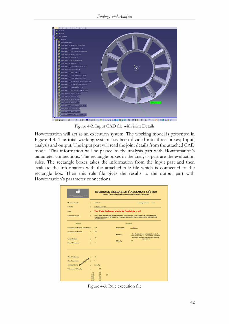
Findings and Analysis
42
Figure 4-2: Input CAD file with joint Details
Howtomation will act as an execution system. The working model is presented in Figure 4-4. The total working system has been divided into three boxes; Input, analysis and output. The input part will read the joint details from the attached CAD model. This information will be passed to the analysis part with Howtomation’s parameter connections. The rectangle boxes in the analysis part are the evaluation rules. The rectangle boxes takes the information from the input part and then evaluate the information with the attached rule file which is connected to the rectangle box. Then this rule file gives the results to the output part with Howtomation’s parameter connections.
Figure 4-3: Rule execution file
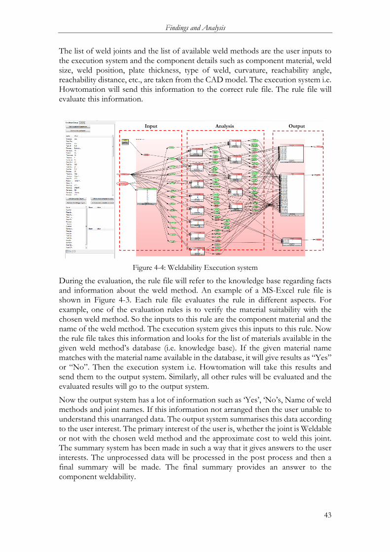
Findings and Analysis
43
The list of weld joints and the list of available weld methods are the user inputs to the execution system and the component details such as component material, weld size, weld position, plate thickness, type of weld, curvature, reachability angle, reachability distance, etc., are taken from the CAD model. The execution system i.e. Howtomation will send this information to the correct rule file. The rule file will evaluate this information.
Figure 4-4: Weldability Execution system
During the evaluation, the rule file will refer to the knowledge base regarding facts and information about the weld method. An example of a MS-Excel rule file is shown in Figure 4-3. Each rule file evaluates the rule in different aspects. For example, one of the evaluation rules is to verify the material suitability with the chosen weld method. So the inputs to this rule are the component material and the name of the weld method. The execution system gives this inputs to this rule. Now the rule file takes this information and looks for the list of materials available in the given weld method’s database (i.e. knowledge base). If the given material name matches with the material name available in the database, it will give results as “Yes” or “No”. Then the execution system i.e. Howtomation will take this results and send them to the output system. Similarly, all other rules will be evaluated and the evaluated results will go to the output system.
Now the output system has a lot of information such as ‘Yes’, ‘No’s, Name of weld methods and joint names. If this information not arranged then the user unable to understand this unarranged data. The output system summarises this data according to the user interest. The primary interest of the user is, whether the joint is Weldable or not with the chosen weld method and the approximate cost to weld this joint. The summary system has been made in such a way that it gives answers to the user interests. The unprocessed data will be processed in the post process and then a final summary will be made. The final summary provides an answer to the component weldability.
Input Analysis Output

Findings and Analysis
44
The welding cost will be estimated separately based on the weld length, weld method, and the weld material. The execution system sends these values directly to the output file. The values will be imported to the cost sheet of the output system. Filler material and weld cost per unit length will be taken from the knowledge base based on the weld method and weld material. After multiplying the weld length with weld cost per unit length, the welding cost will be estimated.
4.2 Prototype Description The prototype has been developed and improved during each action cycle iteration. Five important components are required to build a prototype as specified in section 3.3.4. Getting the evaluation results and estimating the welding cost are the completion criteria for the prototype development.
The prototype begins with the input preparation. A CAD model with weld joints and the joints information serves as an input model. Figure 4-2 depicts the input model developed for the prototype.
Next part of the prototype development is the development of the analysis system. An analysis system consists of three parts. First are weld evaluation rules (i.e. AI). Preparation of rules and their execution plan has been described in section 3.3.4. Second is the making of a knowledge base. Making of the knowledge base and the knowledge base description has been described in section 3.3.4. The third part of the analysis system is the making of an execution system. The execution system became the interface to the user. The execution system has been developed with the Howtomation software. The details of the Howtomation software are explained in section 3.3.5 in the action cycle 3. Figure 4-4 is the developed execution system as a prototype to this thesis work. The workings of this execution system have been explained in section 4.1. The evaluation of rules are in the form of rectangle boxes. They can easily be added, deleted or modified. Basically the rules in the form of rectangle boxes will send the information to the attached MS-Excel files. The MS-Excel rules will evaluate the information and present the output as a result. An example of this MS-Excel rule file is shown in Figure 4-3. Howtomation’s parameter connections will connect this results to the output summary part.
The last part of the prototype development is the making of an output system. The output part is connected with a Results summary file. The Results summary file is also a MS-Excel file. It contains four working sheets. Those are ‘Results’ to record the results from rules, ‘Postprocess’ to process the results (Figure 3-8) in a structured way so that an user can understand the results, ‘cost’ file to analyse the weld cost and the final Summary sheet (Figure 3-7) to give the summary of analysis results. After the evaluation from the rule file, this evaluated results will go to the Results sheet and then the final summary will be prepared after the post process. This results part will refer to the knowledge to estimate the cost. The rectangle box under the output part in the Figure 4-4 is the cost estimation part.

Findings and Analysis
45
Figure 4-5: Output sheet to record results after the analysis
The user will write a list of joint names (required for evaluation) in the parameter object which is named as “Object Name” and the list of weld methods (need for evaluation) in the parameter object which is named as “Weld Method”. As soon as the Howtomation analysis file begins the execution, the program will select the first joint name from the Object list and the first weld name from the weld method list. The knowledge object named as “Input CAD parameters” will receive this joint name and read all corresponding tagged values of that joint named in the CAD model. This values and weld method name become the inputs to the ‘Rule objects’. The rule objects will refer to the attached rule file with these inputs and then give the rule validity and the execution remarks as a decision. Before getting the decision from the rule, the rule file will refer to the information from the Knowledge file. The decisions from all rules will be stored in the Output summary file which is attached in the knowledge object named as “Results” in the Howtomation file. At the same time, the knowledge object named as ‘cost object’ in the Howtomation analysis file refers to the weld method, weld material and weld length’s values. It then estimates the weld cost of that corresponding weld joint for the chosen weld method. While calculating the cost, the cost object will refer to the weld method’s knowledge base. This is the completion of one loop. Then the loop continues with the second weld method in the list for the same weld joint. Once all weld methods in the list are finished, the loop will continue with the second weld joint. The loop will continue till a product of ‘number of weld methods’ and ‘number of weld joints of a component’ times. After completion of the analysis, the screen will appear in green colour. The output of each iteration will be recorded in the summary file connected to the ‘Results’ object in the Howtomation analysis file. These results get summarised and provide a single answer about the weldability of a joint with cost.
Figure 4-6: Cost estimation sheet
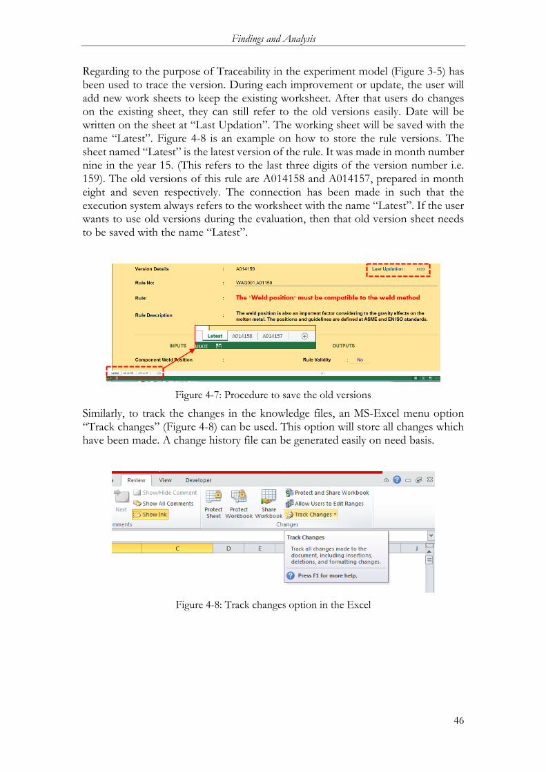
Findings and Analysis
46
Regarding to the purpose of Traceability in the experiment model (Figure 3-5) has been used to trace the version. During each improvement or update, the user will add new work sheets to keep the existing worksheet. After that users do changes on the existing sheet, they can still refer to the old versions easily. Date will be written on the sheet at “Last Updation”. The working sheet will be saved with the name “Latest”. Figure 4-8 is an example on how to store the rule versions. The sheet named “Latest” is the latest version of the rule. It was made in month number nine in the year 15. (This refers to the last three digits of the version number i.e. 159). The old versions of this rule are A014158 and A014157, prepared in month eight and seven respectively. The connection has been made in such that the execution system always refers to the worksheet with the name “Latest”. If the user wants to use old versions during the evaluation, then that old version sheet needs to be saved with the name “Latest”.
Figure 4-7: Procedure to save the old versions
Similarly, to track the changes in the knowledge files, an MS-Excel menu option “Track changes” (Figure 4-8) can be used. This option will store all changes which have been made. A change history file can be generated easily on need basis.
Figure 4-8: Track changes option in the Excel
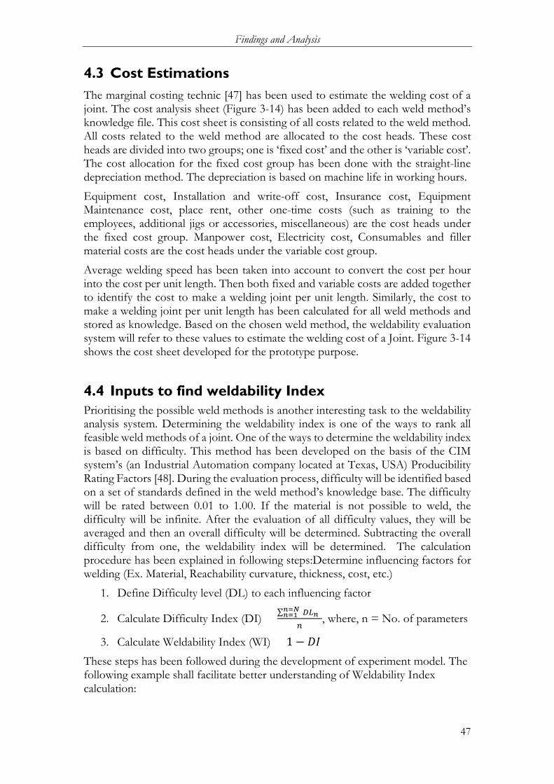
Findings and Analysis
47
4.3 Cost Estimations The marginal costing technic [47] has been used to estimate the welding cost of a joint. The cost analysis sheet (Figure 3-14) has been added to each weld method’s knowledge file. This cost sheet is consisting of all costs related to the weld method. All costs related to the weld method are allocated to the cost heads. These cost heads are divided into two groups; one is ‘fixed cost’ and the other is ‘variable cost’. The cost allocation for the fixed cost group has been done with the straight-line depreciation method. The depreciation is based on machine life in working hours.
Equipment cost, Installation and write-off cost, Insurance cost, Equipment Maintenance cost, place rent, other one-time costs (such as training to the employees, additional jigs or accessories, miscellaneous) are the cost heads under the fixed cost group. Manpower cost, Electricity cost, Consumables and filler material costs are the cost heads under the variable cost group.
Average welding speed has been taken into account to convert the cost per hour into the cost per unit length. Then both fixed and variable costs are added together to identify the cost to make a welding joint per unit length. Similarly, the cost to make a welding joint per unit length has been calculated for all weld methods and stored as knowledge. Based on the chosen weld method, the weldability evaluation system will refer to these values to estimate the welding cost of a Joint. Figure 3-14 shows the cost sheet developed for the prototype purpose.
4.4 Inputs to find weldability Index Prioritising the possible weld methods is another interesting task to the weldability analysis system. Determining the weldability index is one of the ways to rank all feasible weld methods of a joint. One of the ways to determine the weldability index is based on difficulty. This method has been developed on the basis of the CIM system’s (an Industrial Automation company located at Texas, USA) Producibility Rating Factors [48]. During the evaluation process, difficulty will be identified based on a set of standards defined in the weld method’s knowledge base. The difficulty will be rated between 0.01 to 1.00. If the material is not possible to weld, the difficulty will be infinite. After the evaluation of all difficulty values, they will be averaged and then an overall difficulty will be determined. Subtracting the overall difficulty from one, the weldability index will be determined. The calculation procedure has been explained in following steps:Determine influencing factors for welding (Ex. Material, Reachability curvature, thickness, cost, etc.)
1. Define Difficulty level (DL) to each influencing factor
2. Calculate Difficulty Index (DI) = ∑ (𝑛𝑛=𝑁𝑁𝑛𝑛=1 𝐷𝐷𝐷𝐷𝑛𝑛)
𝑛𝑛, where, n = No. of parameters
3. Calculate Weldability Index (WI) = 1 − 𝐷𝐷𝐷𝐷 These steps has been followed during the development of experiment model. The following example shall facilitate better understanding of Weldability Index calculation:
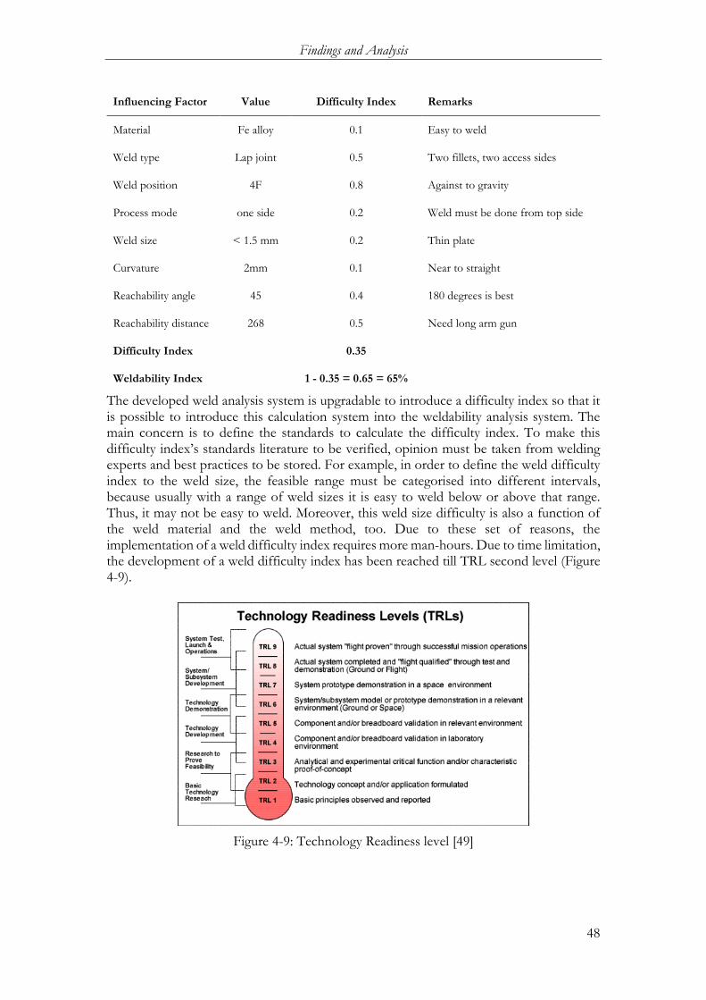
Findings and Analysis
48
Influencing Factor Value Difficulty Index Remarks
Material Fe alloy 0.1 Easy to weld
Weld type Lap joint 0.5 Two fillets, two access sides
Weld position 4F 0.8 Against to gravity
Process mode one side 0.2 Weld must be done from top side
Weld size < 1.5 mm 0.2 Thin plate
Curvature 2mm 0.1 Near to straight
Reachability angle 45 0.4 180 degrees is best
Reachability distance 268 0.5 Need long arm gun
Difficulty Index 0.35
Weldability Index 1 - 0.35 = 0.65 = 65%
The developed weld analysis system is upgradable to introduce a difficulty index so that it is possible to introduce this calculation system into the weldability analysis system. The main concern is to define the standards to calculate the difficulty index. To make this difficulty index’s standards literature to be verified, opinion must be taken from welding experts and best practices to be stored. For example, in order to define the weld difficulty index to the weld size, the feasible range must be categorised into different intervals, because usually with a range of weld sizes it is easy to weld below or above that range. Thus, it may not be easy to weld. Moreover, this weld size difficulty is also a function of the weld material and the weld method, too. Due to these set of reasons, the implementation of a weld difficulty index requires more man-hours. Due to time limitation, the development of a weld difficulty index has been reached till TRL second level (Figure 4-9).
Figure 4-9: Technology Readiness level [49]
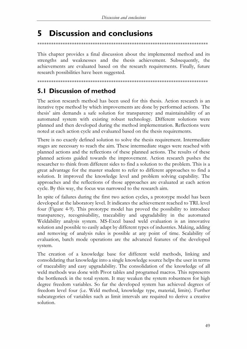
Discussion and conclusions
49
5 Discussion and conclusions **************************************************************************
This chapter provides a final discussion about the implemented method and its strengths and weaknesses and the thesis achievement. Subsequently, the achievements are evaluated based on the research requirements. Finally, future research possibilities have been suggested.
**************************************************************************
5.1 Discussion of method The action research method has been used for this thesis. Action research is an iterative type method by which improvements are done by performed actions. The thesis’ aim demands a safe solution for transparency and maintainability of an automated system with existing robust technology. Different solutions were planned and then developed during the method implementation. Reflections were noted at each action cycle and evaluated based on the thesis requirements.
There is no exactly defined solution to solve the thesis requirement. Intermediate stages are necessary to reach the aim. These intermediate stages were reached with planned actions and the reflections of these planned actions. The results of these planned actions guided towards the improvement. Action research pushes the researcher to think from different sides to find a solution to the problem. This is a great advantage for the master student to refer to different approaches to find a solution. It improved the knowledge level and problem solving capability. The approaches and the reflections of those approaches are evaluated at each action cycle. By this way, the focus was narrowed to the research aim.
In spite of failures during the first two action cycles, a prototype model has been developed at the laboratory level. It indicates the achievement reached to TRL level four (Figure 4-9). This prototype model has proved the possibility to introduce transparency, recognisability, traceability and upgradability in the automated Weldability analysis system. MS-Excel based weld evaluation is an innovative solution and possible to easily adapt by different types of industries. Making, adding and removing of analysis rules is possible at any point of time. Scalability of evaluation, batch mode operations are the advanced features of the developed system.
The creation of a knowledge base for different weld methods, linking and consolidating that knowledge into a single knowledge source helps the user in terms of traceability and easy upgradability. The consolidation of the knowledge of all weld methods was done with Pivot tables and programed macros. This represents the bottleneck in the total system. It may weaken the system robustness for high degree freedom variables. So far the developed system has achieved degrees of freedom level four (i.e. Weld method, knowledge type, material, limits). Further subcategories of variables such as limit intervals are required to derive a creative solution.

Discussion and conclusions
50
Prof. Joel Johansson (Teacher in Product development Engineering Department, Jönköping University) is developing software for data base creation. This software can eliminate the system bottleneck at high degree freedom. Adding the weldability Index calculation and generating the total process plan for all weld operations will fulfil the total purpose of the project.
5.2 Discussion of findings The Weldability analysis method has been described in section 4.1 and the prototype detail has been described in section 4.2. In this part, the thesis evaluation is performed on the basis of the research question and thesis purpose.
5.2.1 Transparency
The term transparency has been explained in section 1.4 that the user is able to read each and every detail of the evaluation and the system working. The working system has been prepared with the Howtomation software shown in the Figure 4-4. The unique advantage of this software is that the user can read a list of input parameters with corresponding values and it is also possible to read; how this parameters are connected? Where the information is flowing? How these inputs are converting into the outputs? What are the details of the output? What is the status of the system execution? Where is the error? All these things can be seen and read from the working screen. All the system working is visible to the user.
The colour of the icons (i.e. knowledge objects, parameters and background screen) indicates the system status and error identification. The arrow direction indicates the information flow direction. The values of inputs and outputs can be read from the parameter icons.
5.2.2 Recognisability
The term recognisability was also explained in section 1.4. It means the working system must be easily understandable to the end user.
For easy understanding the working system has been divided into three parts input, analysis and the output. Those parts are shown in Figure 4-4. The name on each icon helps the user to recognise the details about it. All the working files have been made in MS-Excel. The evaluating procedures, corresponding logics have been written with simple arithmetical (i.e. ‘+’, ‘-’, ‘/’ and ‘*’) and logical (i.e. ‘>’, ‘<’ and ‘=’) operations. The working of the execution system is also recognisable by colours. The results and inputs are also readable to the user during execution. The summary facilitates understanding and the results are presented in the form of ‘Ok’ and ‘Not OK’.
Since the system is an automated system and runs fast during the batch mode operation, the values and colours will changes rapidly. It may be difficult for the user to read the details, but if users run a single operations, they can recognise each detail.

Discussion and conclusions
51
5.2.3 Traceability
The term traceability has been defined as that the user can find the version and amendment details of existing rules and also the details of the evaluation results.
For this purpose in this thesis work, a rule numbering system (Figure 3-5) has been used to trace the version. The date is available on each rule sheet so that user can verify the last updating date. User can also find the old versions of rules on adjacent to the working sheets. There are some commercialised product data management (PDM) systems [46], [45] which are available to handle large number of files with improved versions and modification history. The rule numbering system is an old method and used for this thesis as a substitution of PDM system.
5.2.4 Upgradability
The term upgradability has been defined as the ability to upgrade the entire system consisting of working procedures, evaluation rules, weld knowledge and output.
The working procedure has been created with the Howtomation software where the inputs, rules and the outputs can be added, deleted and modified easily. The user just needs to change the attachment to the knowledge object for changing the procedure. Since the rules are prepared and managed separately by the working system, it is easy for the user to create new rules and attach those to the working system without disturbing others. The knowledge base has been made in such a way that the knowledge summary file gets updated with a single click on the summary file and then the macro program will update the changes from each file stored in the knowledge bank. Newly added weld methods are also possible to be updated in the summary file easily. Similarly, the output file has been made in MS-Excel so that all additions, deletions and modifications are acceptable.
5.2.5 Other Requirements
Apart from the maintainability and upgradability aspects, the developed system can be capable to fulfil the other requirements such as; Scalability foe large scale analysis, welding cost estimation and batch mode compatibility. Scalability
The evaluation rules, number of measuring parameters in the CATIA file, number of the weld joints and number of weld methods are scalable from small quantities to large quantities. The scalability is only limited to the maximum number of knowledge objects allowed in the Howtomation software. It is subjected to licence requirements. The commercial version of Howtomation software is capable to use knowledge objects in a large scale (in thousands) which is sufficient to any type of company.
Discussion and conclusions
52
Cost analysis
Finding the cost to make a weld joint is also part of the thesis requirements. The developed model is now capable to estimate the cost of the selected joint. Marginal costing technic has been used for cost analysis. Figure 3-14 is a cost estimation model for a weld method. The welding cost for a joint has been estimated based on the selected weld method, weld material, average weld speed and weld length.
Batch mode compatibility
The system has been developed in such that it can be possible to operate for batch modes to evaluate all the weld joints automatically. During the batch mode analysis, the working system will consider all existing weld methods for all weld joints. The looping system has been used to operate in batch mode. This looping option is an embedded part in the Howtomation software.
The purpose of this thesis also fulfilled the requirements specified by Mr. Petter Andersson during the visit to GKN. The list of requirements has been specified in section 3.3.1.
The system has been developed in such that the evaluation model is now capable to evaluate all joints of a component in the CAD model by the batch mode operation. The output of the weld analysis for all joints is presented in a summarised form. This output summary is in an easy format with a single sheet. The post process sheet (Figure 3-8) in the output part helps the user to investigate evaluation results in detailed way. This detailed way includes each rule result with corresponding details (This corresponding details are available in the form of remarks). The Evaluation results are in the form such that everyone can understand easily. It is written in ‘OK’ and ‘Not OK’ form. Weldability failures are highlighted with red in the result sheet so that user can identify easily.
Rule number and rule description also available in the result sheet so that user can refer the analysis details in backward investigation. Knowledge, Evaluation intelligence and the execution are separated and stored. Each rule data sheet is managed with version details. The developed system is flexible to manage by the PDM system. The Knowledge, Intelligence and evaluation method are upgradable. All the updates and the changes can be traceable with MS-Excel’s track changes option.
Weldability Index
The calculation procedure of weldability Index has been discussed in the section 4.4. The calculation procedure is a preliminary procedure but most suitable to this evaluation method. The main limitation of this method of calculation is, the user must justify the difficulty of each operation for each weld method and the justified data must be updated according to the work place improvements. The difficulty value assumed in the experiment model is inappropriate. This values are used to verify the method suitability. Means, welding against to gravity may not be difficult in real time, etc.

Discussion and conclusions
53
5.3 Conclusions During the thesis preparation, an automated weldability analysis system has been developed to meet the user requirements in terms of transparency, recognisability, traceability and upgradability. The system has been developed with a framework of CATIA, MS-Excel and specially developed software called ‘Howtomation’. The developed system is capable to analyse the Weldability of a joint from its CAD model. The analysis report will provide feedback to the user to improve the Weldability of a joint and reasons for failure. The weldability index and the welding cost estimation will guides the user to select an economic weld process.
The system works on the basis of available weld methods in terms of weld knowledge and a set of weld evaluation rules. The unique advantage of developed weld analysis system is very flexible for modifications and improvements. The system operations are transparent and recognisable to the user while the versions and updates are traceable and the entire system is upgradable.
One of the bottleneck to the developed weldability analysis system is auto knowledge consolidation, to form a knowledge summary. It is limited to a low degree of freedom variables. Some creative solution needs to be found for the variables with high degree of freedom. Weld gun types and jigs are needed to be introduced in the weld knowledge. Improvement for calculating weldability index and generating auto production sequences are required to finish the entire system development.
There are some commercial softwares like DFMPro [50] available in the market. This software is limited to evaluate Machining, casting, Injection Modelling, Sheet metal forming and assembly analysis. The integration of this thesis work with that software can fulfil the user requirement in terms of all producibility aspects.
5.4 Future Work In order to implement the developed DFM- Weldability analysis system in industrial environment following work to be completed
• Knowledge consolidation of the variables which have high degree freedom, more than six
• Compatibility testing of Rules and Knowledge files with a commercialised PDM systems to manage in large scale
• Definition and testing of Difficulty Index for industrial environment
• Introduction of Weld gun compatibility into the DFM- Weldability analysis system
• Introduction of Weld sequence and the sequence optimisation into the developed DFM- Weldability analysis system
• Breadboard validation of developed DFM- Weldability analysis system in relevant environment
References
54
6 References [1] Hvam, L, Mortensen, NH and Riis, J, Product Customization, Berlin, Germany:
Springer Verlag, 2008. [2] Vinnova, “Challenge-driven innovation - Vinnova’s new strategy for strengthening
Swedish innovation capacity,” information vi 2011:07, Vinnova, Stockholm, Sweden, 2011.
[3] A. Hopgood, Intelligent Systems for Engineers and Scientists, Boca Raton, Florida, USA: CRC Press, Second Edition, 2001.
[4] C. A. V. d. Velden, “Application of Knowledge Based Engineering Principles to Intelligent Automation Systems,” Doctor of Philosophy, RMIT University, 2008.
[5] J. Vallhagen, J. Madrid, R. Söderberg and K. Wärmefjord, “An approach for producibility and DFM-methodology in aerospace engine component development,” in 2nd International Through-life Engineering Services Conference, 2013.
[6] H. Douglas, Grabenstettera and J. M. Usher, “Determining job complexity in an engineer to order environment for due date estimation using a proposed framework,” International Journal of Production Research, vol. 51, no. 19, p. 5728–5740, 2013.
[7] Antoine Brière-Côté, Louis Rivest and Alain Desrocher, “Adaptive generic product structure modelling for design reuse in engineer-to-order products,” Computers in Industry 61, 2010, p. 53–65.
[8] T. Heikkinen and J. Müller, “Assessment of Multidisciplinary Analysis Systems in Aerospace Product Development,” Jönköping University, Jönköping, Sweden, 2015.
[9] M. Stokes, Managing Engineering Knowledge MOKA, London, Great Britain: Professional Engg Publications ltd, 2001.
[10] Shukor, S. A. and Axinte, D. A., “Manufacturability analysis system: Issues and future trends,” International Journal of Production Research, vol. 47, no. 5, pp. 1369-1390, 2009.
[11] “About GKN Aerospace,” [Online]. Available: http://www.gkn.com/aerospace/aboutus/Pages/default.aspx. [Accessed 06 08 2015].
[12] “GKN products and Capabilities,” [Online]. Available: http://www.gkn.com/aerospace/products-and- capabilities/Pages/default.aspx. [Accessed 10 07 2015].
[13] “Webinar Accessing the european aerospace market and supply chain,” [Online]. Available: http://www.slideshare.net/westworldconsulting/webinar-accessing-the-european-aerospace-market-and-supply-chain. [Accessed 28 07 2015].
[14] “GKN Aerospace, SWEDEN,” [Online]. Available: http://www.gkn.com/aboutus/Pages/locations/gkn-aerospace-Trollhattan.aspx. [Accessed 15 07 2016].
[15] “GKN products,” [Online]. Available: http://www.gkn.com/aerospace/products-and-capabilities/Pages/default.aspx. [Accessed 14 07 2015].
[16] P. Meunier, “Software Transparency and Purity,” Communications of the ACM, vol. 51, no. 2, pp. 104-104, Feb 2008.

References
55
[17] D. K. Sobek I., A. C. Ward and J. K. Liker, “Toyota’s principles of set-based concurrent engineering. Sloan Management Review,” vol. 40, no. 2, pp. 67-83, 1999.
[18] O’Donnell, W.J. and Gomba, K.M., “Design for Manufacturability/Continuous Flow Manufacturing: An Operating Procedure,” Design for Manufacturing,, vol. 51, pp. 1-5, 1992.
[19] Maddux, K.C. and Jain, S.C., “CAE for the Manufacturing Engineer:The Role of Process Simulation in Concurrent Engineering. In: Tseng,,” Manufacturing Simulation and Processes, 1986.
[20] Z. Siddique and Z. Yanjiang, “Automatic generation of product family member CAD model supported by a platform using a template approach,” in Proceedings of DETC02: ASME design engineering technical conferences, Montreal, Canada, 2002.
[21] T. Tomiyama and K. Hew, “Knowledge Intensive Computer Aided Design: Past, Present and future,” in Proceedings of IFIP TC WG 5.2: Third workshop on Knowledge intensive CAD, Tokyo, Japan, 1998.
[22] Sriram, R.D, Intelligent Systems for Engineering: A Knowledge-Based approach, London, Great Britain: Springer-Verlag Ltd, 1997.
[23] S. K. Gupta and D. S. Nau, “Systematic approach to analysing the manufacturability of machined parts,” Computer-Aided Design, vol. 27, no. 5, pp. 323-342, 1995.
[24] R. Raffaeli, “Identification of Weld Beads in Assemblies of B-Rep Models,” Computer-Aided Design and Applications, vol. 11, no. 3, pp. 263-274, 2014.
[25] Y. Kwon, T. Wu and J. O. Saldivar, “SMWA: A CAD-based Decision Support System for the Efficient Design of Welding,” CONCURRENT ENGINEERING: Research and Applications, vol. 4, no. 4.
[26] “DFMPro, Geometric Global,” [Online]. Available: http://dfmpro.geometricglobal.com/about-dfmpro/. [Accessed 22 08 2016].
[27] F. Elgh, “Automated engineer-to-order systems – a task-oriented approach to enable traceability of design rationale,” Int. J. Agile Systems and Management, vol. 7, no. 3/4, p. 324–347, 2014.
[28] P. K. Mckinley, “Composing Adaptive Software,” [Online]. Available: https://www.researchgate.net/publication/220476667_Composing_Adaptive_Software.
[29] Blessing, L and Chakrabarti, A., DRM, a Design Research Methodology, London: Springer, 2009.
[30] R. Hannam, “Computer Integrated Manufacturing: From Concepts to Realization,” Harlow, Great Britain, Addison Wesley Longman Ltd., 1997.
[31] Brown, D. H. and Associates, “Knowledge-based engineering systems: applying discipline and technology for competitive advantage,” United States, Gardner Publications, Inc., 2006.
[32] E. De Kock, “Decentralising the codification of rules in a decision support expert knowledge base,” University of Pretoria, 2003.
[33] T. Ho, “K216 C: Studies on intelligence: expert systems and knowledgebased systems,” Japan Advanced Institute of Science and Technology, 2001.
[34] S.L.C. Ferreira, R.E. Bruns, H.S. Ferreira, G.D. Matos, J.M. David, G.C. Brandão, E.G.P. da Silva, L.A. Portugal, P.S. dos Reis, A.S. Souza and W.N.L. dos Santos,

References
56
“Box-Behnken design: An alternative for the optimization of analytical methods,” vol. 597, p. 179–186, 2007.
[35] Box, G.E.P., Hunter, W.G. and Hunter, J.S., Statistics for Experimenters: An Introduction to Design, Data Analysis and Model Building, New York: John Wiley, 1978.
[36] “Thermal Overall Integrated Conception of Aircraft (TOICA) Project,” [Online]. Available: http://www.toica-fp7.eu/. [Accessed 14 12 2015].
[37] H. Tanigawaa, A. Aburadani, S. Shigematsua, N. Takedaa, S. Kakudatea, S. Mori, T. Jokinenb and M. Merola, “Comparative study of laser and TIG welding for application to ITER blanket hydraulic connection,” Fusion Engineering and Design, vol. 87, p. 999–1003, 2012.
[38] H. Gower, R. Pieters and I. Richardson, “Pulsed laser welding of metal-polymer sandwich materials using pulse shaping,” Journal of Laser Applications, vol. 18, no. 1, p. 35 – 41, 2006.
[39] G. Goldkuhl, “ACTION RESEARCH VS. DESIGN RESEARCH: USING PRACTICE RESEARCH AS A LENS FOR COMPARISON AND INTEGRATION,” Tilburg,Netherlands, 2013.
[40] K. Williamson, Research methods for students, academics and professionals:Information management and systems, 2 ed., Centre for Information Studies,Charles Sturt University, 2000.
[41] C. Frayling, “Research in Art and Design,” Royal Collage of Art Research Papers, vol. 1, no. 1, pp. 1-5, 1993.
[42] H. Taba and E. Noel, Steps in the Action Research Process, Victoria, Australia: Deakin University Press, 1997.
[43] João Tiago Matos Marques dos Santos, “Design for Manufacturing – Concept cost evaluation model for fabricated components at Volvo Aero,” Chalmers University of Technology, Göteborg, Sweden, 2012.
[44] M. F. Ashby, Materials Selection in Mechanical Design, 4th, Ed., Oxford, UK,: Elsevier Science & Technology, 2004.
[45] “Product Data Management Applications in Manufacturing,” [Online]. Available: https://www.youtube.com/watch?v=vOQqo-_8F_w. [Accessed 24 12 2015].
[46] “Teamcenter PDM,” [Online]. Available: https://www.youtube.com/watch?v=6zNeunC-SX0. [Accessed 25 12 2015].
[47] T. Lucey, Costing, London: Thomson , 2002. [48] “DESIGN PRODUCIBILITY ASSESSMENT SYSTEM, CIM SYSTEMS,”
[Online]. Available: http://www.google.se/url?sa=t&rct=j&q=&esrc=s&source=web&cd=1&ved=0ahUKEwi-yLjxwoDKAhXFWywKHYO9C1AQFggkMAA&url=http%3A%2F%2Fwww.dtic.mil%2Fdtic%2Ftr%2Ffulltext%2Fu2%2Fa210408.pdf&usg=AFQjCNF98Q_upwHmCYdvrOq_JyiHtBfI5g&sig2=99Pgra9gKRsoYc-Fxyp8vg. [Accessed 11 01 2016].
[49] “Technology Readyness Level,” [Online]. Available: http://alopexoninnovation.com/2013/06/11/effective-technical-risk-assessments-in-new-product-development/. [Accessed 20 12 2015].
[50] “CAD Integrated DFM Software,” [Online]. Available: http://dfmpro.geometricglobal.com/about-dfmpro/. [Accessed 22 08 2015].

References
57
[51] D. H. Grabenstettera and J. M. Usher, “Determining job complexity in an engineer to order environment for due date estimation using a proposed framework,” International Journal of Production Research, vol. 51, no. 19, p. 5728–5740, 2013.
[52] P. Maropoulos, Z. Yao, H. Bradley and K. Paramor, “An integrated design and planning environment for welding: Part 1: Product modelling,” Journal of Materials Processing Technology, vol. 107, no. (1–3), pp. 3-8, 2000.
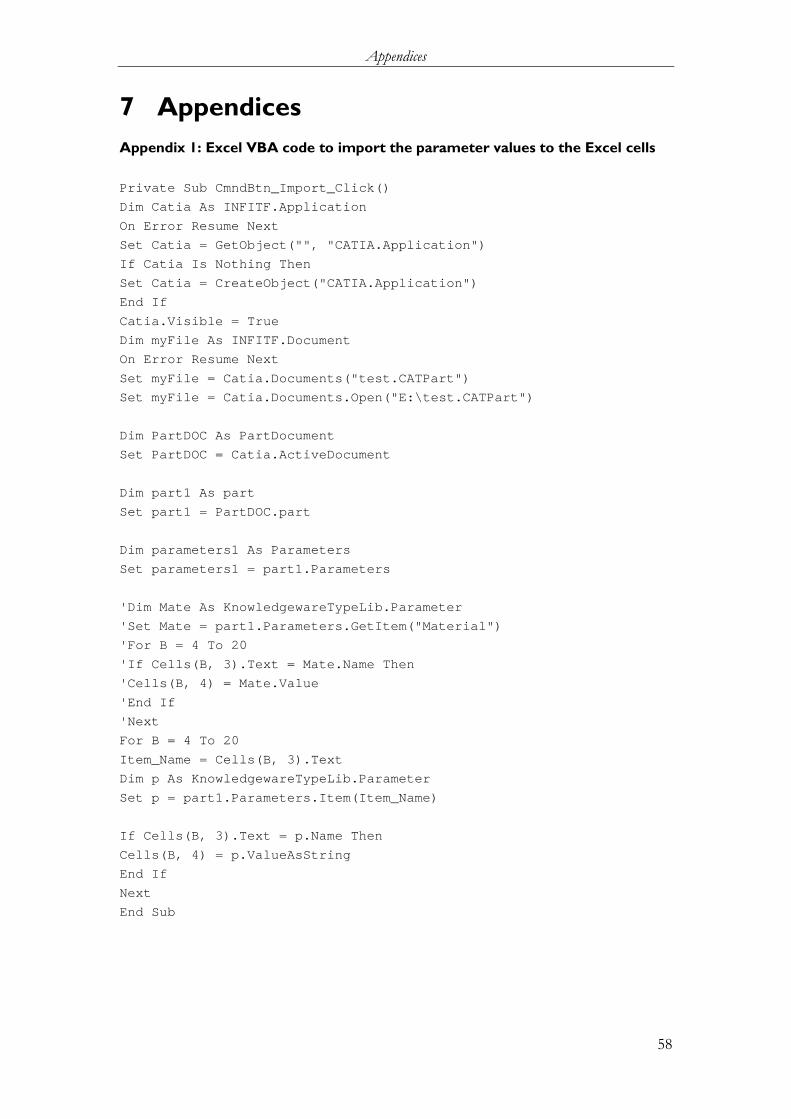
Appendices
58
7 Appendices Appendix 1: Excel VBA code to import the parameter values to the Excel cells
Private Sub CmndBtn_Import_Click()
Dim Catia As INFITF.Application
On Error Resume Next
Set Catia = GetObject("", "CATIA.Application")
If Catia Is Nothing Then
Set Catia = CreateObject("CATIA.Application")
End If
Catia.Visible = True
Dim myFile As INFITF.Document
On Error Resume Next
Set myFile = Catia.Documents("test.CATPart")
Set myFile = Catia.Documents.Open("E:\test.CATPart")
Dim PartDOC As PartDocument
Set PartDOC = Catia.ActiveDocument
Dim part1 As part
Set part1 = PartDOC.part
Dim parameters1 As Parameters
Set parameters1 = part1.Parameters
'Dim Mate As KnowledgewareTypeLib.Parameter
'Set Mate = part1.Parameters.GetItem("Material")
'For B = 4 To 20
'If Cells(B, 3).Text = Mate.Name Then
'Cells(B, 4) = Mate.Value
'End If
'Next
For B = 4 To 20
Item_Name = Cells(B, 3).Text
Dim p As KnowledgewareTypeLib.Parameter
Set p = part1.Parameters.Item(Item_Name)
If Cells(B, 3).Text = p.Name Then
Cells(B, 4) = p.ValueAsString
End If
Next
End Sub

Appendices
59
Appendix 2: Excel VBA Functions to execute the rule Sub A01159LB()
Dim Item_Name As String
Dim Materl As String
Item_Name = "Materials"
Windows("Thesis project.xlsm").Activate
Materl = Application.WorksheetFunction.VLookup(Item_Name, Sheets("Rule Summary").Range("c1:d25"), 2, False)
Dim var As Variant
Windows("LBM.xlsx").Activate
var = Application.Match(Materl, Sheets("Laser Beam Welding").Range("e9:z9"), 0)
If Not IsError(var) Then
Windows("Rules Bank.xlsm").Activate
Sheets("Rules Bank").Select
Cells(4, 16) = "Yes"
Else
Windows("Rules Bank.xlsm").Activate
Sheets("Rules Bank").Select
Cells(4, 16) = "No"
End If
End Sub
*******************************************************************
Sub A01159TIG()
Dim Item_Name As String
Dim Materl As String
Item_Name = "Materials"
Windows("Thesis project.xlsm").Activate
Materl = Application.WorksheetFunction.VLookup(Item_Name, Sheets("Rule Summary").Range("c1:d25"), 2, False)
Dim var As Variant
Windows("TIG.xlsx").Activate
var = Application.Match(Materl, Sheets("TIG").Range("e9:z9"), 0)
If Not IsError(var) Then
Windows("Rules Bank.xlsm").Activate
Sheets("Rules Bank").Select
Cells(4, 17) = "Yes"
Else
Windows("Rules Bank.xlsm").Activate
Sheets("Rules Bank").Select
Cells(4, 17) = "No"
End If
End Sub
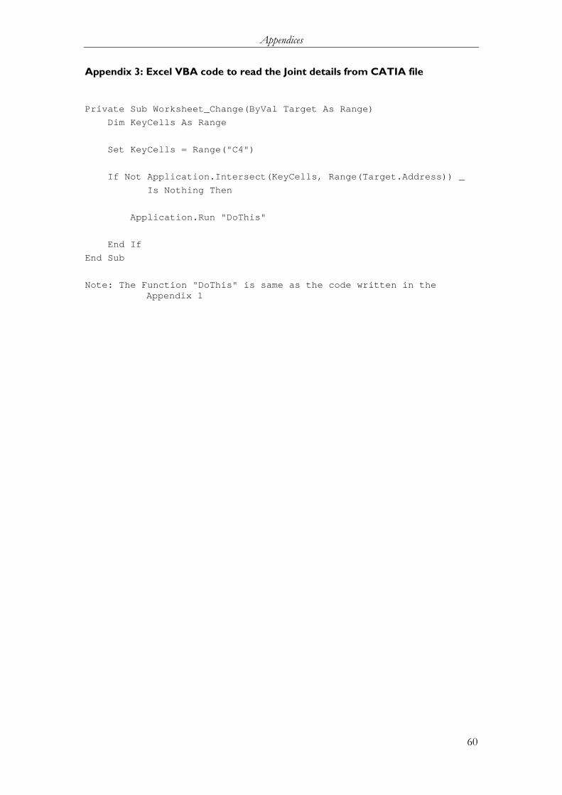
Appendices
60
Appendix 3: Excel VBA code to read the Joint details from CATIA file
Private Sub Worksheet_Change(ByVal Target As Range)
Dim KeyCells As Range
Set KeyCells = Range("C4")
If Not Application.Intersect(KeyCells, Range(Target.Address)) _
Is Nothing Then
Application.Run "DoThis"
End If
End Sub
Note: The Function "DoThis" is same as the code written in the Appendix 1