Development Testing and Subsequent Failure Investigation of ...
14
Development Testing and Subsequent Failure Investigation of a Spring Strut Mechanism Jared Dervan * , Brandan Robertson ** , Lucas Staab + , Michael Culberson ++ and Joseph Pellicciotti +++ Abstract The NASA Engineering and Safety Center (NESC) and Lockheed Martin (LM) performed random vibration testing on a single spring strut development unit to assess its ability to withstand qualification- level random vibration environments. Failure of the strut while exposed to random vibration resulted in a follow-on failure investigation, design changes, and additional development tests. This paper focuses on the results of the failure investigations referenced in detail in the NESC final report [1] including identified lessons learned to aid in future design iterations of the spring strut and to help other mechanism developers avoid similar pitfalls. Introduction Commodities are transferred between the Multi-Purpose Crew Vehicle (MPCV) crew module (CM) and service module (SM) via an external umbilical that is driven apart with spring-loaded struts after the structural connection is severed, as shown in Figure 1. The spring struts must operate correctly for the modules to separate safely. The MPCV program plan did not include development vibration testing of this strut for the Exploration Flight Test 1 (EFT-1) mission, thus any design problems discovered as a result of vibration testing would not have been found until the component verification testing, potentially causing large program schedule delays. The MPCV Program Chief Engineer submitted a request to the NESC to perform random vibration testing on a single spring strut development unit to mitigate this risk. The objective of the NESC assessment was to perform development vibration testing on a flight-like umbilical spring strut and evaluate the strut’s behavior during and after the test. Roles and responsibilities were distributed between NESC personnel and the MPCV Program prime contractor, LM. As part of the test program, low-level vibration and performance tests (consisting of force-displacement curve generation) were to be performed prior to and following a qualification-level random vibration testing to characterize the baseline system response and performance and help detect changes as a result of the random vibration testing. The random vibration portion of the test was to begin at low levels, ramping in increments through maximum predicted environment (MPE) levels to qualification levels (MPE +6 dB for the MPCV Program) and held at qualification levels for 3 minutes in each axis while in a stowed configuration. Pre- and post-test inspections and collection of digital imagery were planned. Following the testing and performance evaluations, the strut was to be disassembled and inspected for damage/wear with a report detailing the findings. During random vibration testing of the last test configuration, the spring strut encountered a failure of the forward locking elements resulting in a rotation of the strut and subsequent fatigue failure. A follow-on root cause investigation was performed that identified supporting rationale for a failure scenario that included aspects of design, analysis, test, and workmanship. Lessons learned pertaining to areas of joint * NASA Marshall Space Flight Center, Huntsville, AL ** NASA Johnson Space Center, Houston, TX + NASA Glenn Research Center, Cleveland, OH ++ Lockheed Martin Space Systems Company, Littleton, CO +++ NASA Goddard Space Flight Center, Greenbelt, MD Proceedings of the 42 nd Aerospace Mechanisms Symposium, NASA Goddard Space Flight Center, May 14-16, 2014 391
-
Upload
khangminh22 -
Category
Documents
-
view
5 -
download
0
Transcript of Development Testing and Subsequent Failure Investigation of ...

Development Testing and Subsequent Failure Investigation of a Spring Strut Mechanism
Jared Dervan*, Brandan Robertson**, Lucas Staab+, Michael Culberson++ and Joseph Pellicciotti+++
Abstract
The NASA Engineering and Safety Center (NESC) and Lockheed Martin (LM) performed random vibration testing on a single spring strut development unit to assess its ability to withstand qualification-level random vibration environments. Failure of the strut while exposed to random vibration resulted in a follow-on failure investigation, design changes, and additional development tests. This paper focuses on the results of the failure investigations referenced in detail in the NESC final report [1] including identified lessons learned to aid in future design iterations of the spring strut and to help other mechanism developers avoid similar pitfalls.
Introduction
Commodities are transferred between the Multi-Purpose Crew Vehicle (MPCV) crew module (CM) and service module (SM) via an external umbilical that is driven apart with spring-loaded struts after the structural connection is severed, as shown in Figure 1. The spring struts must operate correctly for the modules to separate safely. The MPCV program plan did not include development vibration testing of this strut for the Exploration Flight Test 1 (EFT-1) mission, thus any design problems discovered as a result of vibration testing would not have been found until the component verification testing, potentially causing large program schedule delays. The MPCV Program Chief Engineer submitted a request to the NESC to perform random vibration testing on a single spring strut development unit to mitigate this risk. The objective of the NESC assessment was to perform development vibration testing on a flight-like umbilical spring strut and evaluate the strut’s behavior during and after the test. Roles and responsibilities were distributed between NESC personnel and the MPCV Program prime contractor, LM. As part of the test program, low-level vibration and performance tests (consisting of force-displacement curve generation) were to be performed prior to and following a qualification-level random vibration testing to characterize the baseline system response and performance and help detect changes as a result of the random vibration testing. The random vibration portion of the test was to begin at low levels, ramping in increments through maximum predicted environment (MPE) levels to qualification levels (MPE +6 dB for the MPCV Program) and held at qualification levels for 3 minutes in each axis while in a stowed configuration. Pre- and post-test inspections and collection of digital imagery were planned. Following the testing and performance evaluations, the strut was to be disassembled and inspected for damage/wear with a report detailing the findings. During random vibration testing of the last test configuration, the spring strut encountered a failure of the forward locking elements resulting in a rotation of the strut and subsequent fatigue failure. A follow-on root cause investigation was performed that identified supporting rationale for a failure scenario that included aspects of design, analysis, test, and workmanship. Lessons learned pertaining to areas of joint
* NASA Marshall Space Flight Center, Huntsville, AL ** NASA Johnson Space Center, Houston, TX + NASA Glenn Research Center, Cleveland, OH ++ Lockheed Martin Space Systems Company, Littleton, CO +++ NASA Goddard Space Flight Center, Greenbelt, MD Proceedings of the 42nd Aerospace Mechanisms Symposium, NASA Goddard Space Flight Center, May 14-16, 2014
391

design, significance of secondary effects, material selection, and processing, to name a few, were identified to aid in future design iterations.
Figure 1. MPCV EFT-1 CM-SM Umbilical in its Stowed Configuration
Hardware Description and Development
The CM-SM umbilical spring strut consists of multiple piece parts assembled with sliding contact interfaces. A detailed image of the assembly with piece parts identified can be found in Figure 2. The titanium actuator spring is compressed when configured to the strut flight length (780 mm (30.7 in) between end fitting spherical bearings). The compression force is applied to the aft cap, located on the SM side, and piston located internal to the actuator housing. The piston transfers the load to the secondary piston through a contact constraint normal to the strut axis. The contact surface between the piston and secondary piston is permitted to rotate relative to one another and is only opposed by friction. When the strut is permitted to actuate, after release of the umbilical interface at the CM, the compressed spring forces the piston forward sliding through the actuator housing and driving the secondary piston forward. Dual spring-loaded latches slide over the piston as it moves through the actuator housing. Once the piston traveled past the latches, the latches are forced into the actuator housing cavity prohibiting the piston from returning to its pre-actuation position. During the actuation, the driven secondary piston will move until it contacts the aluminum honeycomb damper dissipating the energy of the forward stroke.
Spring Struts
392

Figure 2. MPCV CM-SM Umbilical Spring Strut Detail Cross Section
The forward lug interfaces with the umbilical side of the CM-SM umbilical mechanism while the aft cap interfaces with the SM side. A spherical bearing in both end fittings is pinned in a clevis and permits some misalignment when installed in the flight vehicle or test fixtures. The umbilical side test interface consisted of a test fixture and the SM side interface a flight-like actuator bracket. The forward lug and aft cap have threaded aluminum 7050 interfaces to their adjoining parts, the secondary piston and actuator housing, respectively. The threads for these parts were cut and have an applied polyester locking patch and single braided lockwire between the elements to serve as secondary locking features. As-designed, aluminum 7050 parts with sliding contact interfaces, the secondary piston, forward cap, actuator housing, and piston, have a General Magnaplate proprietary Tufram L-4 surface treatment. This treatment is a polymer (i.e., polytetrafluoroethylene (PTFE)) impregnated Type III hard anodize to minimize stick/slip. During NESC fabrication, a Type III hard anodize was mistakenly applied instead of the as-designed surface treatment. The test hardware surface treatment was considered to provide a conservative wear condition at the sliding surfaces and deemed acceptable by the joint NESC and LM team for the development test program. After compressing the strut to the stowed flight length, a retention tool (shown in Figure 3) was applied to sustain the compressed state of the strut. The retention tool interfaces with two through tooling holes located in the secondary piston and the body of the actuator housing. The tool was applied after initial assembly, after pre- and post-random vibration performance testing, and during reconfiguration between random vibration test axes.
Figure 3. CM-SM Umbilical Spring Strut with Retention Tool
393

Development Testing
Random vibration testing was performed after initial performance testing (described below) to assess the umbilical spring struts capability to meet applicable functional requirements following exposure to qualification levels of random vibration environments. This process included acceptance testing intended to screen production units for latent manufacturing, material, and workmanship defects. Two random vibration environments in each axis were provided by LM for the umbilical and SM side inputs. Several options were initially evaluated for the random vibration test configuration before reaching an agreement to utilize two T-2000 Unholtz-Dickie 80068 N (18000 lbf) shakers with two shaker control systems and two random vibration environments applied simultaneously and uncorrelated. By using two shakers, the umbilical strut was exposed to the required environments and was the closest to qualification of a “flight-like” configuration. The dual shaker configuration can be found in Figure 4.
Strain gages (four total) were initially installed only on the aft housing due to channel number limits. After Z-axis testing, three strain gages were added to the secondary piston and used in place of three of the aft housing gages. The control 3-axis accelerometers for test control, channels 1-12, were placed on the test fixtures (two on each end).
Figure 4. Dual Shaker Configuration (Z-axis)
The test proceeded with the Z-axis first followed by the X-axis and finally the Y-axis. Each testing axis followed a similar pattern: minimum workmanship screening (MWS) and acceptance level loads were applied for 60 seconds, followed by the qualification levels for 3 minutes, and finally another MWS for comparison to the first MWS to assess changes in stiffness. Figure 5 illustrates discrepancies in responses that were seen upon comparison of the pre- and post-qualification level MWS runs in the Z-axis. The difference was found to be loosening of the aft cap during the qualification level testing. The aft cap was re-torqued and additional lockwire at a larger gauge was applied for follow-on testing. Figure 5 shows the minimal difference in the X-axis pre- and post-qualification level MWS runs. Additionally, the assessment team noted debris was observed exiting the spring strut when qualification levels were
394

applied in both Z- and X-axes. A borescope was used after testing in each axis to qualitatively assess the magnitude of internal wear and provide a comparison from axis to axis. For the Z- and X-axis testing, the hardware was exposed to the target levels with no significant (i.e., operation-inhibiting) damage observed and thus deemed successful.
Figure 5. Typical Pre- and Post-Qualification MWS Differences (Z-axis [left]; X-axis [right])
The Y-axis was anticipated to be the worst environment for the hardware. MWS and acceptance levels were completed in the Y-axis. However, during the qualification level test, a distinct change in the sound and response produced by the hardware was observed 27 seconds into the full level qualification run. A lack of clear visual failure indicators coupled with ill-defined criteria for test stoppage resulted in continuation of the testing to the full duration (3 minutes). Upon completion of the test, the NESC team found the secondary piston had failed at the aft tooling hole and the lockwire restraining the forward lug from rotating had failed (Figure 6). Due to the failure of the spring strut hardware, no further random vibration testing could be completed and the hardware was taken back for investigation and performance testing. Note that even though the test hardware incurred a failure, the testing was ultimately considered successful because it flagged design deficiencies before they were encountered late in the test and verification cycle.
Figure 6. Structural Failure of Secondary Piston at Aft Tooling Hole [left]; Lockwire Failure at Forward Lug [right]
In the performance test, the development spring strut was exercised at a slow rate from the flight configuration (stowed) to the extended position (Figure 7) to measure the load versus displacement characteristics and observe the function of the anti-back-travel latches. In the wear-in test, the strut was
Pre-Qualification
Post-Qualification
395

exercised 15 times at nominal deployment speeds (394 mm/s (15.5 in/s)). During the test, the strut was stroked from the flight length to the extended position to reach steady state performance and to observe potential wear or performance degradation. After wear-in, the strut was stored at the flight configuration with the retention tool applied and shipped to the random vibration testing facility. After failure during the random vibration testing, the strut was returned to the performance testing facility with a truncated secondary piston to remove the failed portion of the strut. Using a cupping interface, post-vibe performance deployment tests were performed with the strut assembled in the load frame. The post-vibration performance test served primarily to assess whether there were any large excursions from the nominal force-deflection curve. These excursions could be indicative of significant damage to the spring strut sliding surface. The post-vibration performance test satisfied the nominal expected end of travel force of 165 N ± 27 N (37 ± 6 lbf) and resulted in nominal engagement of the anti-back travel latches. Force versus displacement within the expected tolerance yielded acceptable force margin based on the next high assembly assumptions and calculations. A comparison of the pre- and post-random vibration performance test is shown in Figures 8.
Figure 7. Test Setup for Performance Testing (Pre-Vibe [left] and Post-Vibe [right])
396

Figure 8. Force versus Displacement Plot for Slow Speed Extension
Root Cause Investigation and Findings
Immediately following the strut failure, the joint NESC and LM team generated a fishbone diagram. Individual elements were classified as aspects of design, analysis, test, and/or workmanship. Related and supporting evidence was gathered to disposition those elements as either most probable cause, contributor, credible, credible but unlikely, or non-credible. The NESC/LM joint investigation occurred over a month whereupon, due to MPCV Program schedule pressure, LM chose to implement corrective actions addressing identified proximate causes and assumed ownership of the CM-SM umbilical spring strut development test program. The NESC team continued the investigation in an effort to identify root cause and the most probable failure scenario. Supporting analyses were completed, photographic evidence was reviewed, and inspections were conducted to provide rationale for fishbone element classifications shown in Figure 9. Detailed information regarding the root cause investigation, including classification definition, can be found in the full NESC assessment report [1].
397

Figure 9. Fishbone Diagram
Failure Scenario Supporting Elements The following key findings related to the root cause investigation elements were utilized to devise a most probable failure scenario. 1. Test Video and Strain Gauge Data: Immediately after application of the qualification levels, the SM
side assembly (aft cap, actuator housing, and forward cap) rotated clockwise (looking SM to umbilical side). Lagging this rotation, the secondary piston was observed to rotate counterclockwise. Inspection of data from strain gauges mounted on the secondary piston and visual indicators of mounted accelerometers indicated a rotation of approximately 90 degrees. Strain gauge data with indicators of tooling hole orientation relative to the Y-axis applied load can be found in Figure 10. Approximately 27 seconds after application of qualification levels (242 seconds) there was a noticeable decrease in noise and strut dynamic response. No noticeable damage was observed, so the test was continued to the full duration at 395 seconds.
2. Forward Lug Locking Patch Design: Load requirements for the locking patch were not defined prior to developmental testing. Designers did not anticipate any applied loosening torque to aid in the patch sizing in part due to the fact that the strut would be in compression during vibration testing. Additionally, it is not standard practice to perform supporting analyses of locking patch capability. Locking patches are not intended to serve as torque reaction features; rather, they should be used to reduce the rate of preload loss in a joint. The prevailing torque requirement was less than the minimum recommended running torques specified for fine thread series threads 38.1 mm (1.500 in) in diameter or less. The locking patch vendor indicated the patch size was small relative to the thread size and pitch to which they were applied.
3. Joint Characteristics: The threads utilized for testing had an as-designed preload limited to 25 percent of the tensile yield strength (Fty), which was constrained by Material Usage Agreement (MUA) dictating sustained stresses to be less than 50 percent Fty due to stress corrosion cracking (SCC) susceptibility of the joint material, aluminum 7050-T7451. Preload is the primary means of joint loosening when subjected to cyclic, transverse loads. Typical torques sufficient to prevent loosening
398

during vibration are in the 70 percent Fty range [2]. Preload was applied to the joint by tightening to a predetermined torque range. Galling, typical for threaded aluminum joints, would have added to the resistive torque measured during application of a final assembly torque and resulted in a reduced as-assembled preload. Additionally, the profile of the forward lug and aft cap could have contributed to lower preload values given the end fittings were hollow and more susceptible to flexure and joint relaxation. The requirements and analysis methods utilized in the assessment of joint preload [3, 4] did not consider bending as a potential source of joint separation and are primarily focused on typical bolted joints and fasteners, the definitions of which are not completely applicable to the spring strut joints.
4. Strut Retention Design and Fatigue Analysis: The retention tool utilized to hold the spring strut in a compressed state interfaces with secondary piston tooling holes and clamps onto the actuator housing body just aft of the actuator housing-to-forward cap interface. The two tooling holes were machined as a part of the spring strut assembly process whereupon the forward lug is fastened to the secondary piston, the location of the tooling holes relative to this subassembly are identified, and the forward lug is removed and holes machined. Since this machining operation occurs during the assembly phase, the tooling holes did not have the surface treatment that was applied to the rest of the secondary piston.
Prior stress and fracture analyses did not include the tooling holes, and the secondary piston was not considered fracture critical. Large structural margins in this analysis deemed the secondary piston satisfied the definition of a ‘low risk’ component and were subsequently classified as non-fracture critical. These prior analyses were based on flight load factors found to be inadequate and inconsistent with the EFT-1 flight configuration. After the secondary piston failure, an updated fatigue analysis was performed accounting for the off-nominal secondary piston rotation to quantify the Cumulative Damage Index (CDI) using Rayleigh’s distribution and Miner’s Rule for response to the base input Power Spectral Density (PSD). In summary, the analysis results showed exceedance of the secondary piston fatigue life capability at the tooling hole (CDI = 1.519 > 1.0) when subjected to Y-axis qualification levels in a maximum bending condition. After the failure, the spring strut was evaluated by LM and Marshall Space Flight Center (MSFC) failure analysis groups with both groups concluding the structural failure occurred at the aft-most secondary piston tooling hole initiated in fatigue followed by ductile overload. The opposite side of the failed tooling hole also showed the beginnings of fatigue cracking.
5. CG Offset: Through hardware inspection and as-designed tolerance limitations on select dimensions, the spring strut center of gravity (CG) could be approximated as 1.09 mm (0.043 in) offset for the forward assembly (i.e., secondary piston, forward lug, actuator spring, and piston) and 0.76 mm (0.030 in) offset for the aft assembly (i.e., aft cap, actuator housing, forward cap, damper module assembly, latch, retention spring, and fasteners) in the Z-axis. With random vibration loads applied to the strut, the CG offset in the forward assembly could contribute to a moment being applied in the direction of rotation of the secondary piston during the Y-axis random vibration testing. Other factors that may have contributed to the applied torque on secondary piston are the static, induced torque from compression of the actuator spring and the instrumentation mass offset from the strut centerline, neither of which was incorporated into the pre-test analysis. Application of recorded time history data permitted an across-the-board comparison of applied torque versus estimated torque capability as a function of CG offset. It was shown that the required torque to overcome the forward lug-to-secondary piston secondary locking feature’s capability would have been exceeded given a 3- and 4-σ load and 1.09-mm (0.043-in) CG offset. Similarly, reasonably attainable CG offsets would have resulted in significant induced torques relative to the predicted capability of the joint for a 3-σ load. Therefore, the CG offset in the forward assembly could have led to induced torques capable of overcoming the torque-resistive capability of the forward strut interface with reasonable assumptions, known input environments, and predicted dynamic responses. Note that no such reasonably attainable CG offset would have induced significant enough torque to
399

overcome the aft cap-to-actuator housing secondary locking feature with increased capability (augmented after Z-axis testing).
6. Spring Effects: In addition to bias torques induced by compression of the in-line spring, hand calculations confirmed the potential for an offset spring mass. Given the free length, compressed length, spring diameter, and pitch, the titanium spring would have experienced buckling in its compressed state. As a significant mass contributor, this buckling would have further offset the CG from the strut centerline. Evidence of this offset can be found in wear observed internal to the actuator housing from an apparent contact with the spring.
7. End Fitting Rotational Offset: Indications of wear are evident on the end fittings and adjoining clevises (Figure 11). Contact due to misalignment/rotational offset would have imparted a force off-axis from the strut and induced a torque applied to the end fittings. If the force was sufficient to overcome resistive elements of the joint, then the end fittings could have tightened or loosened. Loosening at the forward strut interface would have permitted an applied torque to more easily rotate the secondary piston relative to the forward lug.
Figure 10. Strain Gauge Data and Strut Rotation
Figure 11. Wear Post-Vibration Testing (Forward Lug [left]; Test Fixture [right]) Failure Scenario The following failure scenario was identified to best correlate with the evidence collected during the root cause investigation. Due to the varied classifications of elements identified, this failure scenario should not be considered definitive. Technical limitations for failure scenario supporting elements are provided and discussed in reference 1.
400

During vibration testing there was contact between the aft cap and SM side actuator bracket and the forward lug and text fixture, with significant wear observed during post-test inspection. This produced a constraint and source of induced reaction force off-axis from the strut. The strut design also permitted a CG offset due to a combination of sliding contact interfaces, machining tolerances, non-axisymmetric nature of select piece parts, elastically buckled spring, and gravity loads as installed in the random vibration test fixture. The design also did not include an alignment feature integral to the strut, therefore forward lug and aft cap strut end fitting alignment was not guaranteed and permitted rotational misalignment between the two rod ends. In the first test configuration (Z-axis), this contact constraint, combined with inertial forces from an offset of the strut CG and maximum SM side environments, resulted in an induced loosening torque on the aft cap. The lack of prevailing torque from an undersized aft cap locking patch increased the joint’s susceptibility to loosening. The aft cap was observed to have loosened after Z-axis testing whereupon it was retightened to the required torque. Lockwire was then re-applied in larger quantities and gauge thickness to further increase the torque reaction capability of the joint. In the last test configuration (Y-axis), a similar contact condition induced a torque at the forward strut interface. The maximum umbilical side environments were applied during Y-axis testing, which, when combined with the CG offset, induced a significant torque about the forward lug. Given a contact condition, again observed through post-test inspection, the forward lug relative to the secondary piston could have been free to rotate in the direction of tightening while contacting the test fixture off-axis from the strut centerline in the direction of loosening. The contact condition would have induced a torsional load to loosen the forward cap-to-secondary piston interface. Once the inertia-induced torque exceeded the capability of the joint which includes a combination of breakaway torque, prevailing torque from the locking patch, and lockwire capability, the secondary piston rotated relative to the forward lug breaking the lockwire. At this point the resistive torque was limited to that provided by the undersized locking patch. The rotation continued until the CG offset was small enough relative to the applied force vector that the prevailing torque of the locking patch exceeded the applied torque (i.e., approximately 90 degrees). Due to the rotation, strut tooling holes, nominally in the neutral bending axis during the Y-axis vibration test, were placed in maximum bending. Once the fatigue life capability at the tooling hole was exceeded, the secondary piston failed by crack growth and overload.
Additional Development Testing
After assessing the results of the NESC-led test and identifying proximate causes of the failure, LM reclaimed responsibility for further strut development testing. Programmatic pressure drove LM to make immediate, low-impact design changes based on proximate cause. The NESC continued the investigation into root cause in parallel with the spring strut redesign effort.
The NESC team was kept apprised of the redesign activities by the MPCV CM subsystem management team. LM made design changes intended to prevent loosening of the threaded parts and eliminate fatigue initiation sites, then retested the strut. These changes included an increase in the size of the secondary locking patches, quantity and diameter of lockwire, and preload at the end fitting joints (50 percent of Fty). Additionally, the tooling holes were removed and a new retention tool design was devised. Once the initial redesign effort was complete, LM began with the Y-axis test, which was the worst case and the axis in which the secondary piston failed. Shortly after reaching qualification levels, the strut suffered another failure. This time, the forward lug fractured at the secondary piston interface. A subsequent investigation by LM determined fatigue failure was the cause and that the corrections made appeared to be working up to the point at which the testing was stopped. The LM retest had reused a majority of the hardware from the original test unit (including the forward lug) without a residual life assessment. Analysis revealed the fractured rod end had exceeded its fatigue life capability. Gapping in the joint between the rod end and the secondary piston exacerbated the problem.
401
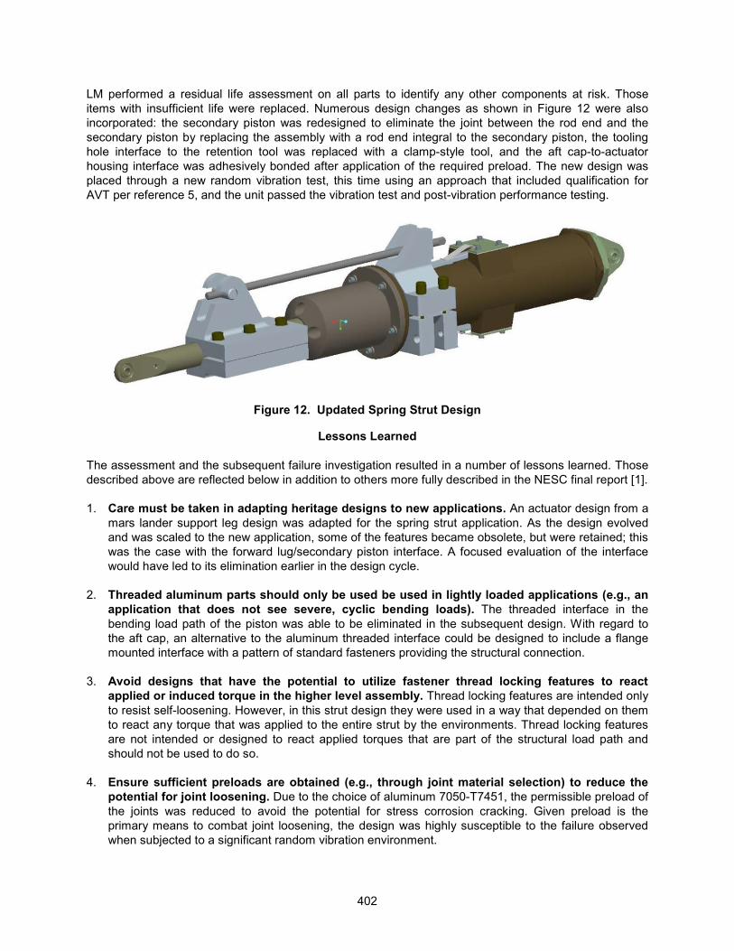
LM performed a residual life assessment on all parts to identify any other components at risk. Those items with insufficient life were replaced. Numerous design changes as shown in Figure 12 were also incorporated: the secondary piston was redesigned to eliminate the joint between the rod end and the secondary piston by replacing the assembly with a rod end integral to the secondary piston, the tooling hole interface to the retention tool was replaced with a clamp-style tool, and the aft cap-to-actuator housing interface was adhesively bonded after application of the required preload. The new design was placed through a new random vibration test, this time using an approach that included qualification for AVT per reference 5, and the unit passed the vibration test and post-vibration performance testing.
Figure 12. Updated Spring Strut Design
Lessons Learned
The assessment and the subsequent failure investigation resulted in a number of lessons learned. Those described above are reflected below in addition to others more fully described in the NESC final report [1]. 1. Care must be taken in adapting heritage designs to new applications. An actuator design from a
mars lander support leg design was adapted for the spring strut application. As the design evolved and was scaled to the new application, some of the features became obsolete, but were retained; this was the case with the forward lug/secondary piston interface. A focused evaluation of the interface would have led to its elimination earlier in the design cycle.
2. Threaded aluminum parts should only be used be used in lightly loaded applications (e.g., an
application that does not see severe, cyclic bending loads). The threaded interface in the bending load path of the piston was able to be eliminated in the subsequent design. With regard to the aft cap, an alternative to the aluminum threaded interface could be designed to include a flange mounted interface with a pattern of standard fasteners providing the structural connection.
3. Avoid designs that have the potential to utilize fastener thread locking features to react
applied or induced torque in the higher level assembly. Thread locking features are intended only to resist self-loosening. However, in this strut design they were used in a way that depended on them to react any torque that was applied to the entire strut by the environments. Thread locking features are not intended or designed to react applied torques that are part of the structural load path and should not be used to do so.
4. Ensure sufficient preloads are obtained (e.g., through joint material selection) to reduce the
potential for joint loosening. Due to the choice of aluminum 7050-T7451, the permissible preload of the joints was reduced to avoid the potential for stress corrosion cracking. Given preload is the primary means to combat joint loosening, the design was highly susceptible to the failure observed when subjected to a significant random vibration environment.
402

5. Conduct machining operations prior to surface treatments to reduce the potential for crack initiation. Machining of the holes after applying the anodic coating likely influenced crack initiation of ~12 µm (4.7E-4 in) depth through the anodic coating and into the base material. The tooling hole machining process may have contributed to the fatigue crack initiation. MSFC failure analysis noted that ‘[h]ard anodized coatings reduce the fatigue life and increase the number of crack initiation site [sic] when applied to aluminum 7050-T7451.’ There is evidence that ‘[a]nodic oxidation of light alloys reduces bending endurance limits by as much as 39 percent'.
6. Utilize dedicated tooling for locking patch process development. This prevents unneeded
cycling of the test article or flight unit’s threads during the locking patch development. 7. Utilize visual movement indicators (e.g., torque striping) for threaded joints. The umbilical strut
had torque stripes applied to certain indicators that were of high value during the investigation. However, not all threaded interfaces had torque stripes so the state of some could not be ascertained. Torque striping is typically very easy and inexpensive to apply.
8. Conduct testing to determine the required limits on running torque for joint designs not
conforming to available standards and specifications. The running torques and preload torques found in most tables have been determined through testing of specific joint combinations. Applying those torques to configurations other than those from which the values were derived may result in large differences from what is needed. In the case of this strut, the material modulus was three times lower than a steel fastener and the threaded body was hollow, generating a much different stiffness in the joint than assumed in the torque tables.
9. Perform a bounding fatigue analysis in all possible orientations on mechanism components that are subject to rotation. The fatigue analysis assumed that the strut remained in its ideal rotational alignment, resulting in the tooling holes being at the neutral axis of the strut. However, normal limits of rotation allowed by the strut design could move these holes somewhat out of the neutral axis and begin to have an impact on fatigue life. Fatigue analysis (as well as all other analyses) should examine the worst-case orientations allowed by the design, not just the ideal orientation.
10. Review requirements, references, and methodologies used in analyses for design
applicability. The requirements and analysis methods utilized in the assessment of joint preload did not consider bending as a potential source of joint separation. Additionally, the references are primarily focused on typical bolted joints and fasteners, the definitions of which are not completely applicable to the spring strut joints. This resulted in a false confidence in the understanding of the behavior of these joints.
11. Assess the contribution of assumed secondary effects (e.g., CG offsets, induced compression
spring static torques, nonlinear behavior, etc.) to the analysis results, and perform an analysis and correlation study that reflects the major contributors. Assumptions about what will be a small contributor to strut response to environments are appropriate for initial design phases, but those assumptions should be checked via sensitivity studies or other means once the design and analysis are more fully developed. In this case, some of the factors assumed to be unimportant turned out to have non-negligible effects on the hardware.
403
Conclusions
The strut, with corrective actions employed, has since successfully completed qualification and acceptance vibration testing with no failures or anomalies and is slated to fly on the Exploration Flight Test-1 (EFT-1) in September, 2014. While no single root cause was identified, numerous contributors and credible elements were found that may have attributed to the failure. Based on these elements, a most probable failure scenario was identified that points to a number of design and process deficiencies that led to a contact condition with the interfacing test hardware, that, when combined with a center of gravity offset of the mechanism assembly and significant applied environments, produced a loosening torque at the forward lug-to-secondary piston interface overcoming the resistive torque of the remaining locking elements and a subsequent rotation of the secondary piston. The tooling holes in the secondary piston, nominally located in the neutral bending axis, were then subjected to maximum bending stresses. When the fatigue life at the hole stress concentration was exceeded, the secondary piston failed.
Results from this assessment identified key lessons learned for the spring strut design and mechanisms in general. These key takeaways focus on design as well as process concerns in areas of design, analysis, test, and workmanship. The valued added by the development test program will help satisfy the future needs of the MPCV through increased confidence in the mechanism’s reliability and ability to meet future programmatic constraints.
References
1. Dervan, Jared; Staab, Lucas; Robertson, Brandan; Song, Kyong; Irvine, Tom; Knight, Joseph. Multi-Purpose Crew Vehicle (MPCV) Crew Module (CM) – Service Module (SM) Umbilical Spring Strut Testing. Doc. no. 11-00747. November 14, 2013
2. Design and Development Requirements for Mechanisms. NASA-STD-5017. June 13, 2006 3. NASA Space Transportation System: Space Shuttle Criteria for Preloaded Bolts. NSTS 08307A. July
6, 1998 4. NASA Technical Memorandum: Preloaded Joint Analysis Methodology for Space Flight Systems.
NASA-TM-106943. December 1995 5. Mechanical Engineering Design, 5th Edition. Joseph Shigley. November 1, 1988
404
![Testing Testing [Read-Only] - Czone - East Sussex](https://static.fdokumen.com/doc/165x107/6327b2a26d480576770d6757/testing-testing-read-only-czone-east-sussex.jpg)