Development of Fit Envelopes To Promote Compatibility ...
126
DOT HS 812 610 September 2018 Development of Fit Envelopes To Promote Compatibility Among Vehicles and Child Restraint Systems
-
Upload
khangminh22 -
Category
Documents
-
view
5 -
download
0
Transcript of Development of Fit Envelopes To Promote Compatibility ...

DOT HS 812 610 September 2018
Development of Fit Envelopes
To Promote Compatibility
Among Vehicles and
Child Restraint Systems

DISCLAIMER
This publication is distributed by the U.S. Department of Transportation, National
Highway Traffic Safety Administration, in the interest of information exchange.
The opinions, findings, and conclusions expressed in this publication are those of
the authors and not necessarily those of the Department of Transportation or the
National Highway Traffic Safety Administration. The Unites States Government
assumes no liability for its contents or use thereof. If trade or manufacturers’
names or products are mentioned, it is because they are considered essential to the
object of the publications and should not be construed as an endorsement. The
United States Government does not endorse products or manufacturers.
Suggested APA Format Citation:
Klinich, K. D., Boyle, K. J., Malik, L. J., Manary, M. A., Eby, B. J. & Hu, J. (2018, September).
Development of fit envelopes to promote compatibility among vehicles and child
restraints (Report No. DOT HS 812 610). Washington, DC: National Highway Traffic
Safety Administration.

i
Technical Report Documentation Page 1. Report No.
DOT HS 812 610 2. Government Accession No.
3. Recipient's Catalog No.
4. Title and Subtitle
Development of Fit Envelopes to Promote Compatibility Among Vehicles and Child Restraints
5. Report Date
September 2018
6. Performing Organization Code
7. Authors
Klinich, Kathleen D., Boyle, Kyle J., Malik, Laura J., Manary, Miriam A., Eby, Brian J., Hu, Jingwen
8. Performing Organization Report No.
UMTRI-2015-24
9. Performing Organization Name and Address
University of Michigan Transportation Research Institute 2901 Baxter Rd. Ann Arbor MI 48109
10. Work Unit No. (TRAIS)
11. Contract or Grant No.
12. Sponsoring Agency Name and Address
National Highway Traffic Safety Administration 1200 New Jersey Avenue SE. Washington, DC 20590
13. Type of Report and Period Covered Final, January 2014-August 2015
14. Sponsoring Agency Code
15. Supplementary Notes
16. Abstract
This project developed fit envelopes representing the space occupied by small, medium, and large rear-facing and forward-facing child restraints that can be used as tools for promoting compatibility between vehicles and child restraints. The approach applies the envelope method used by the International Standards Organization (ISO) to the U.S. market, by considering the range of child restraint sizes in the 2014 U.S. market and the more commonly used method of installation with flexible Lower Anchors and Tethers for Children (LATCH). Thirty-one child restraints representing a range of sizes, manufacturers, and product types were scanned and installed in vehicles. The installed positions of the child restraints were measured in 10 late-model vehicles. A comparison of the installed positions of the child restraints in vehicles was done virtually using Hypermesh. Starting with the envelope geometries used by the ISO, envelope shapes were modified to represent small, medium, and large rear-facing and forward-facing child restraints. When possible, envelope dimensions were harmonized with the ISO envelopes. To promote compatibility, child restraints should be able to fit in one or more applicable envelopes at an acceptable orientation when the envelope is rotated 15° relative to horizontal (to represent installed orientations on a typical vehicle seat cushion angle). To promote compatibility from the vehicle side, at least one rear-facing and one forward-facing envelope should be able to be installed in each vehicle rear seating position. Although the evaluation of fit can be performed virtually using computer-aided design, physical representations of the envelopes were also constructed. Four sets of nesting boxes were built. For child restraint evaluation, the largest rear-facing and forward-facing envelope geometry can be modified with foam inserts to represent the medium and smaller sizes. For vehicle evaluation, a wooden base is installed in the vehicle using flexible LATCH belts. Different components are added to represent the small, medium, and large sizes. Test procedures have been drafted to describe setup of vehicles, child restraints, and the evaluation process. 17. Key Word
misuse, child restraint installation, child restraint volumes, compatibility
18. Distribution Statement
This document is available to the public through the National Technical Information Service, www.ntis.gov.
19. Security Classif. (of this report) 20. Security Classif. (of this page) 21. No. of Pages
126
22. Price
Form DOT F 1700.7 (8-72) Reproduction of completed page authorized

ii
TABLE OF CONTENTS
List of Figures ............................................................................................................................................... iii
List of Tables ................................................................................................................................................. v
Acknowledgments ........................................................................................................................................ vi
Introduction .................................................................................................................................................. 1
Motivation ................................................................................................................................................. 1
ISO Fit Envelopes ....................................................................................................................................... 2
Objectives and Approach .......................................................................................................................... 2
Methods ........................................................................................................................................................ 4
Child Restraint Selection ........................................................................................................................... 4
Vehicle Selection Process ........................................................................................................................ 12
Test Matrix .............................................................................................................................................. 15
Scan and Orientation Measurements ..................................................................................................... 17
Envelope Design Process......................................................................................................................... 19
Results ......................................................................................................................................................... 24
Initial Proposed Designs .......................................................................................................................... 24
First Prototype Evaluation ...................................................................................................................... 33
Revised Designs ....................................................................................................................................... 37
Final Designs ........................................................................................................................................... 42
Discussion ................................................................................................................................................... 52
References .................................................................................................................................................. 54
Appendix A: Photos of Physical Envelopes ............................................................................................... A-1
Appendix B: Envelope Testing Instructions ............................................................................................... B-1
Appendix C: CRS in Envelopes .................................................................................................................... C-1
Appendix D: Envelopes in Vehicles ........................................................................................................... D-1

iii
LIST OF FIGURES
Figure 1. Example of a rear-facing CRS and its scanned geometry. ....................................................... 17
Figure 2. Example of geometry from a vehicle scan. ............................................................................. 18
Figure 3. Example of CRS geometry positioned relative to seating position using reference
coordinates. ............................................................................................................................. 19
Figure 4. Installed RF CRS positions in four vehicles compared to the ISO R3 envelope. ...................... 20
Figure 5. Envelope design that fits around RF CRS................................................................................. 20
Figure 6. Placement of preliminary envelope in a sample vehicle. ........................................................ 21
Figure 7. Lower gap too large (greater than 100 mm) ........................................................................... 21
Figure 8. Upper gap too large (greater than 50 mm) ............................................................................. 22
Figure 9. Lower gap acceptable (less than 100 mm). ............................................................................. 22
Figure 10. FF CRS installations in four vehicles compared to the ISO F3 envelope. ................................ 23
Figure 11. ISO F3 envelope “stretched” to fit around acceptable FF CRS installations in four vehicles. . 23
Figure 12. Revised proposal to develop long (left) and tall (right) RF CRS. .............................................. 24
Figure 13. Comparison of proposed long (red), tall (blue), and large (green) envelopes. ....................... 25
Figure 14. ISO R1 compared to three estimated installed profile of shell portion of a RF CRS. .............. 25
Figure 15. Proposals for FF envelopes: FS (yellow), FM (orange), FL (red). ............................................. 26
Figure 16. Angle versus distance of belt path contact location to LA for RF 2L and 2C installations by
vehicle type. ............................................................................................................................ 27
Figure 17. Angle versus distance of belt path contact location to LA for RF 2L and 2C installation by
CRS manufacturer. ................................................................................................................... 28
Figure 18. Angle versus distance of belt path contact location to LA for FF 2L and 2C installations by
vehicle type. ............................................................................................................................ 29
Figure 19. Angle versus distance of belt path contact location to LA for FF 2L and 2C installation by
CRS manufacturer. ................................................................................................................... 29
Figure 20. Drawing of attachment points and belt path corridors for RF envelope. ............................... 31
Figure 21. Drawing of attachment points and belt path corridors for FF envelope. ............................... 32
Figure 22. Tether location that can be used with all three envelopes representing
common attachment location marked with X. ....................................................................... 33
Figure 23. Initial RM prototype. ............................................................................................................... 33
Figure 24. Example of RF-only CRS that would fit with carry handle in upright position
if lid was used. ......................................................................................................................... 35
Figure 25. Examples of different level indicators. .................................................................................... 35
Figure 26. Examples of different recline levels for different child weights. ............................................ 36
Figure 27. One CRS did not fit with fabric covers in place (left) but did when covers over side
elements were shifted (right). ................................................................................................. 36
Figure 28. Some CRS did not contact the bottom of the envelope.......................................................... 36
Figure 29. Concept for reconfigurable RFCRS envelope; drawing with dashed line indicates lateral
extent of envelope. ................................................................................................................. 38
Figure 30. FFveh base (green) plus two components added to create FS. ................................................. 39

iv
Figure 31. FFveh base (green) plus four components to create FM, and one more component to
create FL. ................................................................................................................................. 39
Figure 32. Original proposed design of FS envelope falls outside space occupied by U.S. CRS
and could cause issues placing in rear seat. ............................................................................ 40
Figure 33. RF CRS geometries overlaid with envelopes. Dashed line indicates modification to
shorten bottom envelope dimension. ..................................................................................... 41
Figure 34. FF CRS geometries overlaid with envelopes. Dashed line indicates modification to
shorten bottom envelope dimension. ..................................................................................... 41
Figure 35. FL (red) and FM (gold) top contours before (left) and after (right) incorporating industry
feedback. ................................................................................................................................. 42
Figure 36. Final dimensions of FF envelopes. ........................................................................................... 42
Figure 37. Final dimensions of RF envelopes. .......................................................................................... 43
Figure 38. The bottom of the RFCRS structure must fall below the dashed orange line. .......................... 44
Figure 39. Recaro Proride has similar fit problem in FL and vehicle. ....................................................... 46
Figure 40. RF CRS that could not be installed at an acceptable angle in the vehicle. .............................. 47
Figure 41. Same RF CRS did not meet bottom contact (left) or angle criteria (right). ............................. 47
Figure 42. Locations for assessing gaps with FF CRS. ............................................................................... 48
Figure 43. Location of front seat used in ECE assessment of envelope fit. .............................................. 53

v
LIST OF TABLES
Table 1. Number of products by type and manufacturer. ...................................................................... 5
Table 2. Definition of size code ............................................................................................................... 6
Table 3. Rear-facing child restraint sizes by their rear-facing weight limit and manufacturer. ............. 7
Table 4. Forward-facing harnessed child restraint sizes by their forward-facing weight limit and
manufacturer. ........................................................................................................................... 8
Table 5. List of products, sizes, weight limits, and measurement status. .............................................. 9
Table 6. Distribution of products by size categories. ............................................................................ 11
Table 7. Child restraints purchased for current study .......................................................................... 12
Table 8. Top-selling 2013 vehicles, plus measurement status ............................................................. 13
Table 9. Selection of new vehicles to measure to create proportional representation of
manufactures .......................................................................................................................... 14
Table 10. CRS size groups and sizes included in each ............................................................................. 15
Table 11. Child restraints sorted by test group and size group .............................................................. 16
Table 12. Installation matrix ................................................................................................................... 17
Table 13. CRS fit in prototype RM envelope ........................................................................................... 34
Table 14. Evaluation of RFCRS in envelopes. .......................................................................................... 45
Table 15. Evaluation of FF CRS in envelopes. ......................................................................................... 49
Table 16. Vehicle assessments with RFveh envelopes ............................................................................. 50
Table 17. Vehicle assessments with FFveh envelopes .............................................................................. 51

vi
ACKNOWLEDGMENTS
This work was funded by the National Highway Traffic Safety Administration under cooperative
agreement DTNH22-10-H-00288 with the University of Michigan.
We would like to acknowledge Nichole Orton, Kevin Weise, Katie Uvick, Frank Perkins, and Juan Madrid
for their help in constructing envelopes, developing test procedures, and making drawings.

1
INTRODUCTION
Motivation
Caregivers often struggle to correctly install child restraint systems (CRS) in their vehicles. Child restraint
installation errors occur frequently, as documented in laboratory studies and observational field studies
(Decina & Lococo, 2005; Decina & Lococo, 2007; Dukehart, Walker, Lococo, Decina, & Staplin, 2007;
Greenwell, 2015; Jermakian et al., 2014; Klinich et al., 2013a and 2013b; Klinich, Manary, Flannagan,
Malik, & Reed, 2010; Koppel & Charlton, 2009; Mirman, Curry, Zonfrillo, Corregano, Seifert, & Arbogast,
2014; Tsai & Perel, 2009). In some cases, difficulties arise because some combinations of child restraints
and vehicles are incompatible. Examples of incompatibilities include the following.
Interference between the head restraint and forward-facing (FF) CRS
Highly contoured vehicle seat cushions that do not permit the CRS to have firm contact with the
seat
Gaps between the back or base of the CRS and vehicle seat cushion or seat back because of
incompatible geometries
Rear-facing (RF) CRS cannot be installed at correct angle because of interference with the
vehicle front seat
RF CRS requiring aftermarket adjustments, such as pool noodles, to achieve correct angle
because of incompatibility between CRS and the vehicle seat cushion angle
Seat belt or LATCH belt cannot be adequately tightened because of geometric incompatibilities
between the CRS belt path and the vehicle anchor geometry
CRS cannot be installed in adjacent vehicle seating positions
These issues are not likely to subside, particularly in light of the trend to keep children seated in child
restraints longer. In 2011 the National Highway Traffic Safety Administration recommended that
children remain rear-facing as long as possible, and the American Academy of Pediatrics (AAP)
recommended that children remain rear-facing at least through their second birthday. They also
recommend keeping a child in a forward-facing harnessed restraint as long as possible before switching
to a belt-positioning booster seat. In response, child restraint manufacturers have redesigned RF CRS to
accommodate larger children; maximum RF weight limits frequently reach 35 or 40 lb. Many FF CRS now
have upper weight limits of 65 lb or more. Another factor that could potentially increase the size of CRS
is the proposal to modify FMVSS No. 213, Child Restraint Systems, to add side impact testing
procedures. At the same time, fuel economy requirements are motivating vehicle manufacturers to
reduce vehicle size and mass. As a result, rear seat compartment space can become smaller.
In 2011 NHTSA proposed a voluntary vehicle/child restraint fit evaluation program that would
encourage vehicle manufacturers to provide information to consumers about compatibility for
vehicle/child restraint pairings (76 FR 10637, 2011). Vehicle manufacturers would publish lists of child
restraints that are compatible with a particular vehicle based on several key installation factors. Some of
the comments responding to this proposal pointed out the issue that CRS designs evolve more quickly
than vehicle designs. A 2015 version of a particular CRS might fit in a 2015 vehicle model, but the 2018

2
version of the CRS may not. With over 100 CRS models available each year, the large number of possible
combinations of vehicles, seating positions, and CRS models would be challenging to assess.
ISO Fit Envelopes
The International Standards Organization (ISO) has developed procedures to try to match the size of CRS
with the available interior volume of vehicle seats to help inform consumers’ purchasing choices and to
aid in vehicle and CRS design decisions. The organization’s TC22/SC12/WG1 [Ignition Equipment
Working Group] issued ISO 13216-3:2006(E) (ISO, 2006) to define a classification system for child
restraints and vehicles that helps consumers choose CRS and vehicles that are dimensionally compatible.
The standard defines eight envelopes: three for rear-facing CRSs, three for forward-facing CRSs and two
for car beds. Modifications to the standard to add an envelope for booster seats have been recently
proposed (ISO, 2015).
A previous University of Michigan Transportation Research Institute (UMTRI) project performed for
NHTSA (Hu, Manary, Klinich, & Reed, 2015) used computer simulation to evaluate the FF and RF ISO
13216-3:2006(E) envelopes relative to rear seat compartments from vehicles and CRS in the U.S. market.
Three-dimensional geometry models for 26 vehicles and 16 convertible CRS developed previously were
used. Geometric models of three forward-facing and three rear-facing CRS envelopes prescribed by the
ISO were constructed. A virtual fit process was developed that followed the physical procedures
described in the ISO standards. The results showed that most of the RF CRS could fit in at least one of
the current ISO RF envelopes, but that half of the FF CRS evaluated could not fit in any of the FF
envelopes. From the vehicle perspective, vehicles could usually accommodate most of the FF envelopes.
However, most vehicles evaluated could accommodate the smallest RF ISO envelope, but not the
largest.
These results suggest that the current ISO envelopes could not be used to assess the range of vehicle
and child restraint products available in the United States due to differences in product shapes. While
the FF ISO envelopes fit in the vehicles, FF U.S. child restraints often do not fit in the envelopes. The
smallest RF ISO envelope fit in most vehicles, but very few RF CRS fit in this envelope.
This previous project concluded that the ISO fit envelopes are not entirely compatible with the range of
child restraint products available in the United States. As a result, the current project was proposed to
determine how to adapt the ISO envelope method for the U.S. market.
Objectives and Approach
The objective of this project is to develop CRS fit envelopes that would allow improved compatibility
between U.S. vehicles and CRS using a procedure modeled after the ISO envelope strategy. The
following steps were taken to achieve this goal:
1) Existing scans in UMTRI CRS database were reviewed to determine their usability for the project.
About 18 to 20 more child restraints were digitized to capture the newest product contours.

3
2) Eight to 10 more 2012-2014 vehicle rear seats were digitized, including the center seat contour,
to capture the seat contours (particularly head restraint designs) and key reference points in
rear seats of newer vehicles.
3) Multiple CRS restraints were installed in the center and outboard positions of the scanned
vehicles using LATCH. Locations of key landmarks were documented to provide information on
realistic positioning of CRS and envelopes within vehicle seats.
4) The research team worked with NHTSA personnel to develop the strategy for generating sets of
CRS fit envelopes representing the range of typical U.S. CRS. Possible harmonization with at least
some dimensions of the ISO fit envelopes was considered during the process.
5) Features on the envelopes were included that allow physical and virtual installation into a
vehicle using flexible LATCH.
6) Physical versions of the CRS fit envelopes were constructed.
7) A procedure for installing the fit envelopes into vehicles was developed that allows both
physical and virtual installation in vehicles and considered the installed orientation and position
of the child restraints installed in step 3.
8) The envelopes and procedures were used to assess fit of CRS within the envelope and the fit of
the envelopes within the vehicle.

4
METHODS
Child Restraint Selection
To begin, child restraint manufacturer websites were checked to make a comprehensive list of child
restraint products currently in production as of February 1, 2014. These products met the standards of
the most recent FMVSS No. 213 update. Table 1 shows the list of manufacturers, total number of
products, and number of products in each child restraint category. The number in parentheses indicates
an estimated number of product molds; products that had the same external height, width, depth, and
function were assumed to be manufactured from the same mold. For the purposes of judging external
size, these were considered “sister” products even if they have different features or masses. Because
the term “3-in-1” is used differently by different manufacturers, 3-in-1 products that are used rear-
facing, forward-facing, and as a booster are counted under convertibles in this study, while those that
are used forward-facing and under multiple booster modes are counted under combination seats. Table
1 also includes a code used to identify each manufacturer for the current study.

5
Table 1. Number of products by type and manufacturer.
Manufacturer ID RF only Convertible Combination Booster
Baby Trend BT 3 (2) 2
Britax BR 3 (2) 8 (3) 3 2 (1)
Bubble Bum BB 1
Chicco CH 3(2) 1 1
Clek CL 1 3 (2)
Combi CO 1 1 1
Cybex CY 2
Diono DI 3 (1) 2
Dorel (All Brands) DO 11 (5) 21 (19) 5 15
Dream on Me DR 1
Evenflo EV 3 (2) 8 (5) 5 (2) 7
Graco GR 4 (2) 4 (3) 2(1) 2
Harmony HA 1 7 (6)
Kiddy KI 2
Kids Embrace KE 1
Lilly Gold LG 1
Orbit Baby OB 1 1
Peg Perego PP 1 1 1
Recaro RE 2 (1) 1 1
Summer Infant SI 1
The First Years FY 2 3(2) 2
UPPA Baby UP 1
Total 37(25) 55(40) 20(16) 47(43)
Each product was given both a product code and a size code. For the product code, the first digit
corresponds to the type of product: R (rear-facing only), C (convertible), F (combination), and B
(booster). The next digits correspond to the manufacturer code listed in Table 1, and the last digit
numbers the products within that category for the manufacturer. Thus for BabyTrend, the three rear-
facing only products would be coded as RBT1, RBT2, and RBT2, because two of the products appear to
be sister products made from the same mold.
To indicate the product size, each product was given a three-letter code corresponding to the Height,
Width, and Depth of the product as defined in Table 2. Among all the products, the range of values on
each of the three dimensions was divided into five categories (petite, small, medium, large, grande)
based on the distribution of values on that dimension. Thus a product with height of 26 in, width of 20.5
in, and depth of 21 in would be coded as size LMM, while one with a height of 17.5 in, 25 in, 26.5 in
would be coded as size SGL. For reference, the widths of all ISO envelopes are 17.3 in (440 mm), placing
them in the S width category. The heights range from 600 to 720 mm (23.6 in to 28.3 in), while the
depths range from 535 to 780 mm (21.1 in to 30.7 in), which place them in the M and L height and depth
categories.

6
Table 2. Definition of size code
Height (in) Width (in) Depth (in)
Smallest (petite) (P) <15 < 16 <15
Small (S) 15.0-19.9 16.0-18.5 15.0-19.9
Medium (M) 20.0-24.9 18.6-20.9 20.0-24.9
Large (L) 25.0-29.9 21.0-24.9 25.0-29.9
Largest (grande) (G) 30+ 25+ 30+
Products were then sorted by their rear-facing and forward-facing weight limits. Table 3 lists the size
codes for all rear-facing products by the upper occupant weight limit and manufacturer, while Table 4
provides the same information for the forward-facing harnessed products. In both tables, convertibles
are indicated by standard font, while italics indicate either a rear-facing only or forward-facing only
restraint. The number in parentheses next to a size code indicates the number of models falling within
that size. Bold text indicates child restraints for which scans of a product with the same name were
already in the UMTRI database. In Table 3, products with maximum rear-facing limits of 22 lb were
considered category R1, while those with maximum limits of 30 lb were called R2. Products with RF
weight limits from 32-40 lb are grouped together (blue columns=R3), as are those with RF weight limits
over 40 lb (gray columns=R4.) In Table 4, products were grouped into three FF maximum weight limit
categories: 40-50 lb (F1), 55-65 lb (F2), and > 65 lb (F3).
When choosing child restraints for measurement in this study, the goal was to collect at least six
products within each weight limit grouping of multiple sizes from a variety of manufacturers.
Underlining indicates products that were selected for measurement in this study. Bold text indicates
products that have been measured for the study that are still being sold. Eleven products are rear-facing
only (italics), six are convertibles, two are combination, and one is a booster. Priority was given to
products with sister products, particularly those in more than one weight limit category. After scanning
the listed products, the database includes scans representing 9 of 12 RF (22), 9 of 11 RF (30), 25 of 65 RF
(32-40), 2 of 4 RF (> 40), 10 of 21 FF (40-50), 17 of 38 FF (55-65), and 9 of 22 FF (> 70 w/LATCH).

7
Table 3. Rear-facing child restraint sizes by their rear-facing weight limit and manufacturer.
R1 R2 R3 R4
Manufacturer RF22 RF30 RF32/ 33
RF35 RF40 RF45 RF50
Baby Trend LSL* LSL* LSL
Britax SSG, SSL (2)
LMM (2) LMM, LSM (5)
Chicco MSM LSS (2)
LMM
Clek LSG
Combi LPS LSL
Cybex MSL SSL
Diono LSS* LSS (2)*
Dorel (All Brands)
GSS, LSG MSG
(4)
MSS LMS, LSS*, LSS,
MSL (3), MSL (2),
GSS
LMM, LMP, LSM, GMS (2), GPS, LMM, LMM, LMM, LMM, LSM, LSS*, MSP (2)
Dream on Me LSM
Evenflo LSP LML (2), LML, LSL, LSL(3), LSM
Graco MSL* LMS*, MSL*
SMG (2) LMM, LML, LMS*, LMP (2)
Lilly Gold SSM
Orbit Baby LMS LMS
Peg Perego LSL LMS
Recaro
Summer Infant
LMS
The First Years GSS, MMM (2), SGL, SGM
UPPA Baby LSL
Total 12 11 3 23
Already measured
0 1 0 3 5 (+1)
Proposed 5 (+1) 6 0 2 4 (+1)
Total measured
6 7 16
Key: Italics=rear-facing only; others are convertibles. Underline=proposed, Bold=already measured,
*same shell used for products with different maximum weight limits

8
Table 4. Forward-facing harnessed child restraint sizes by their forward-facing weight limit and manufacturer.
F1 F2 F3
Manufacturer FF40 FF50 FF55 FF65 FF70 FF80+
Baby Trend GLP GSS
Britax LMM LSM* LSM (4)*, LMM, LMM
GMM GMM, GMM, GSS
(2)
Chicco LMM LSS
Clek LSG SSP
Combi LPS LMS
Diono F LSS LSS (2)
Dorel (All Brands)
LSS (2), MMP,
LMS
LMS, LMS,
LSS, GSS
LMM, LMP, GPS, LMM,
LMM, LMM, LSM, MMP,
MSP(2), GPS, LSS
GMS (2), LMM, MMM, MSL,
LSM
LPS, LSS, GSS, LSP, LSS, LSS,
SML
Evenflo LSL (3), LSS
LMM* LML (2), LML, LSL, LSM, LMM
(2)*
GMS, GPP, LSS, LMS,
LSS
Graco LMS* LMS* LMM, LML, LMM*,
LSS, LMM
Harmony GSS GSM, GSSS, GSS,
GSS
Kids Embrace LSS
Lilly Gold SSM
Orbit Baby LMS
Peg Perego LMS LSS
Recaro LMP (2) GSP, GMS
The First Years MMM (2), SGM SGM, SSL
Total 20 38 46
Already measured
2 3 (+1) (+1) 6 2
Proposed 1 0 0 4 2 2
Total 7 10 6
Key: Italics=forward-facing only; others are convertibles. Underline=already measured, Bold=proposed,
*same shell used for products in different weight categories
Overall, the scanned child restraints represent 54 of the 161 different child restraint products available
for sale in February 2014 as listed in Table 5, together with specific dimensions of each product. In
addition, these products span the general range of sizes that apply to all products, including boosters.
Table 6 shows the distribution of products by size code. The list of the measured (M), proposed (P), and
sister (S) products are listed in Table 5, as well as the size code and weight limits. When choosing from
among sister products, the least expensive option was selected as indicated in Table 7.

9
Table 5. List of products, sizes, weight limits, and measurement status.
Manufacturer Product Type CODE Ht W Dep SIZE Limit 1 Limit 2 Status RFCat FFCat
Baby Trend TrendZ FastBack 3-in-1 combo FBT1 31.0 17.5 17.8 GSS FF70 HB100 P N F3
Baby Trend Flex-Loc rf only RBT1 25.0 16.5 26.0 LSL RF30 P R2 N
Baby Trend EZ Flex-Loc rf only RBT1 25.0 16.5 26.0 LSL RF22 S R1 N
Britax Roundabout conv CBR3 26.0 18.5 21.0 LSM RF40 FF55 M R3 F2
Britax Boulevard conv CBR3 26.0 18.5 21.0 LSM RF40 FF65 S R3 F2
Britax Highway conv CBR3 26.0 18.5 21.0 LSM RF40 FF65 S R3 F2
Britax Marathon conv CBR3 26.0 18.5 21.0 LSM RF40 FF65 S R3 F2
Britax Pavilion conv CBR3 26.0 18.5 21.0 LSM RF40 FF65 S R3 F2
Britax Frontier 90 combo FBR1 36.0 19.0 21.0 GMM FF90 HB120 M? N F3
Britax B-SAFE rf only RBR2 15.5 17.5 27.5 SSL RF30 P R2 N
Britax BOB B-SAFE rf only RBR2 15.5 17.5 27.5 SSL RF30 S R2 N
Chicco KeyFit 30 rf only RCH1 28.5 17.3 15.0 LSS RF30 P R2 N
Chicco KeyFit 30 Magic rf only RCH1 28.6 17.4 15.1 LSS RF30 S R2 N
Chicco KeyFit rf only RCH2 22.0 17.0 24.0 MSM RF22 P R1 N
Diono Radian R100 conv CDI1 28.5 17.0 16.0 LSS RF40 FF65 M R3 F2
Diono Radian R120 conv CDI1 28.5 17.0 16.0 LSS RF45 FF80 S R4 F3
Diono Radian RXT conv CDI1 28.5 17.0 16.0 LSS RF45 FF80 S R4 F3
Dorel RodiFix booster BDO13 18.5 19.5 29.5 SML HB120 P N F3
Dorel onSide air conv CD013 26.5 17.5 17.0 LSS RF40 FF40 S R3 F1
Dorel Scenera conv CDO13 26.5 17.5 17.0 LSS RF35 FF40 M R3 F1
Dorel Alpha Omega Elite conv CDO2 25.3 20.0 19.5 LMS RF35 FF50 M R3 F1
Dorel Pria 70 conv CDO5 29.8 20.5 18.5 GMS RF40 FF70 P R3 F3
Dorel Guide 65 Sport conv CDO6 30.5 14.0 18.5 GPS RF40 FF65 P R3 F2
Dorel 3-in-1 conv CDO7 26.5 21.0 20.5 LMM RF40 FF65 M R3 F2
Dorel Summit combo FDO4 28.0 20.0 19.5 LMS FF40 HB100 M N F1
Dorel Mico rf only RDO2 28.5 17.5 30.9 LSG RF22 P R1 N
Dorel Comfy Carry rf only RDO3 23.5 17.0 30.0 MSG RF22 P R1 N
Dorel Comfy Carry Elite rf only RDO3 23.5 17.0 30.0 MSG RF22 S R1 N

10
Manufacturer Product Type CODE Ht W Dep SIZE Limit 1 Limit 2 Status RFCat FFCat
Dorel Comfy Carry Elite Plus rf only RDO3 23.5 17.0 30.0 MSG RF22 S R1 N
Dorel Disney Comfy Carry Elite Plus rf only RDO3 23.5 17.0 30.0 MSG RF22 S R1 N
Dorel Prezi rf only RDO5 21.5 16.8 15.0 MSS RF30 P R2 N
Evenflo Symphony LX All-In-One conv CEV1 25.5 21.0 28.0 LML RF40 FF65 M R3 F2
Evenflo Symphony DLX All-In-One conv CEV1 25.5 21.0 28.0 LML RF40 FF65 S R3 F2
Evenflo Tribute LX conv CEV4 25.5 18.5 27.6 LSL RF40 FF40 P R3 F1
Evenflo Tribute Select conv CEV4 25.5 18.5 27.6 LSL RF40 FF40 S R3 F1
Evenflo Tribute Sport conv CEV4 25.5 18.5 27.6 LSL RF40 FF40 S R3 F1
Evenflo Maestro combo FEV1 27.0 19.0 20.5 LMM FF50 HB110 M N F1
Evenflo SecureKid DLX combo FEV1 26.0 19.0 21.0 LMM FF65 HB110 S N F2
Evenflo SecureKid LX combo FEV1 26.0 19.0 21.0 LMM FF65 HB110 S N F2
Evenflo Nurture rf only REV1 28.0 18.0 11.0 LSP RF22 P R1 N
Graco My Ride 65 conv CGR1 26.0 20.8 27.0 LML RF40 FF65 P R3 F2
Graco ComfortSport conv CGR2 26.5 20.0 18.5 LMS RF30 FF40 M R2 F1
Graco ClassicRide 50 conv CGR2 26.5 20.0 18.5 LMS RF40 FF50 S R3 F1
Graco Argos 70 combo FGR1 29.0 20.0 22.0 LMM FF70 HB100 P N F3
Graco Nautilus 3-in-1 combo FGR2 29.0 20.0 22.0 LMM FF65 HB100 S N F2
Graco SnugRide Classic Connect Infant rf only RGR1 24.2 17.5 26.7 MSL RF22 P R1 N
Graco SnugRide Classic Connect 30 rf only RGR1 24.0 16.5 27.0 MSL RF30 S R2 N
Graco SnugRideClassic Connect 35 rf only RGR2 15.6 18.7 30.7 SMG RF35 P R3 N
Orbit Baby Toddler Car Seat G3 conv COB1 29.0 22.4 18.9 LMS RF35 FF65 M? R3 F2
Peg Perego Primo Viaggio SIP rf only RPP1 25.8 17.3 25.8 LSL RF30 P R2 N
Recaro ProRIDE conv CRE1 29.0 19.0 11.0 LMP RF40 FF70 P R3 F3
Recaro Performance RIDE conv CRE1 29.0 19.0 11.0 LMP RF40 FF70 S R3 F3
The First Years True Fit SI conv CFY1 23.5 23.0 20.0 MMM RF35 FF65 P R3 F2
The First Years True Fit Ialert conv CFY1 22.8 22.5 20.0 MMM RF35 FF65 S R3 F2
M=already measured. S=sister product measured. P=proposed. S=sister product proposed. RFCat and FFCat correspond to max weight limits
defined above.

11
Table 6. Distribution of products by size categories.
Width Depth Height
P S M L G
P P BBB1, BDO8 BCL1, BDO14, BDO15
BEV7
S BDO9, BEV3 BDO2, CCO1 CDO6, FDO1
MSL
S P BHA5 BCL2 (2 CDO19 (2) BDO3, REV1 FRE1
S BDO10 (2), BDO11, BDO12, BEV4,BGR1, BHA6, BHA7 (2)
RDO5 (2) BCH1, BDO4, BDO5, BDO6, BEV5, BEV6, BGR2, BKI2, BPP1, CDO13 (2), CDI1 (3), CDO4, FDO5, FEV2 (2), FK31, RCH1 (2)
BBR1 (2), BDO1, BHA2, BHA3, BHA4, FBT1, DO2, FHA1, RDO1 (2), RFY1
M CLG1 RCH2 CBR3 (5), CDO12, CDO3, CEV5, RDR1
BHA1
L BFY2, RBR2 (2), RCY2
CDO18, RCY1, RDO4 (3), REV2 (2), RGR1(2)
CEV3, CEV4 (3), RBT1 (2), RBT2, RCO1, RPP1, RUP1
G RBR1 RDO3 (4) CCL1, RDO2
M P CDO15, CDO16
CRE1 (2)
S BDO7, BDI2 BCO1, BDI1, BEV2, CDO2, CGR2(2), COB1, CPP1, FDO3, FDO4, ROB1, RSI1
BEV1, BRE1, CDO5 (2),
M CDO14, CFY1 (2)
CBR1, CBR2 (2), CCH1, CDO10, CDO11, CDO7, CDO8, CDO9, CGR3, FEV1 (3), FGR1 (2)
FBR1, FBR2, FBR3
L CEV1 (2), CEV2, CGR1
G
L P FBT2
SM
L BDO13
G RGR2 (2)
G PS
M BFY1, CFY2
L RFY2
G

12
Table 7. Child restraints purchased for current study
Manufacturer Product Type
Dorel Maxi Cosi RodiFix booster
Baby Trend TrendZ FastBack 3-in-1 combo
Graco Argos 70 combo
Dorel Maxi Cosi Pria 70 convertible
Dorel Safety 1st Guide 65 Sport convertible
Evenflo Tribute LX convertible
Graco My Ride 65 convertible
Recaro ProRIDE convertible
The First Years True Fit SI convertible
Baby Trend Flex-Loc rf only
Britax B-SAFE rf only
Chicco KeyFit 30 rf only
Chicco KeyFit rf only
Dorel Cosco Comfy Carry rf only
Dorel Maxi Cosi Mico rf only
Dorel Maxi Cosi Prezi rf only
Evenflo Nurture rf only
Graco SnugRide Classic Connect Infant rf only
Graco SnugRideClassic Connect 35 rf only
Peg Perego Primo Viaggio SIP rf only
Vehicle Selection Process
Ten new vehicles were scanned and used for child restraint installations. To select new vehicles for
testing, a list of the top 50 best-selling vehicles from 2013 was extracted from Automotive News. Table 8
lists for each of these best-selling vehicles if it (or a sister vehicle) had been previously measured, and if
so, what model year was measured.

13
Table 8. Top-selling 2013 vehicles, plus measurement status
2013 Sales Rank Make/Model Measured? Year
1 Ford F150 Y 2011
2 Chevrolet Silverado LTZ Y 2000
3 Toyota Camry Y 2002
4 Honda Accord Y 2004
4 Honda Accord Y 2007
5 Ram 1500 Y 2005
6 Honda Civic Y 2010
7 Nissan Altima Y 2003
8 Honda CR-V Y 2003
9 Toyota Corolla Y 2003
10 Ford Escape M
11 Ford Fusion N
12 Chevrolet Cruze M
13 Hyundai Elantra N
14 Chevrolet Equinox LTZ M
15 Ford Focus Y 2004
16 Toyota RAV4 M
17 Hyundai Sonata Y 2011
18 Chevrolet Malibu Y 2003
19 Ford Explorer Y 2011
20 GMC-Sierra S
21 Jeep Grand Cherokee Y 2004
22 Volkswagen Jetta M
23 Nissan Rogue M
24 Toyota Tacoma Y 2002
25 Toyota Prius Y 2006
26 Chevrolet Impala Y 2011
27 Kia Optima M
28 Jeep Wrangler N
29 Nissan Sentra N
30 Ford Edge N
31 Honda Odyssey M
32 Toyota Highlander N
33 Honda Pilot N
34 Dodge Grand Caravan Y 2011
35 Subaru Forester Y 1998
36 Chrysler 200 M
37 Chrysler Town & Country S

14
2013 Sales Rank Make/Model Measured? Year
38 Toyota Sienna Y 2011
39 BMW 3-series & 4-series N
40 Kia Soul Y 2011
41 Subaru Outback M
42 Nissan Versa Y 2011
43 Toyota Tundra N
44 Volkswagen Passat Y 2002
45 Kia Sorento N
46 Mazda 3 Y 2011
47 Lexus RX N
48 GMC Terrain N
49 Dodge Charger N
50 Chevrolet Traverse Y 2011
Y=previously digitized, S=sister vehicle measured, M=measured in current study, N=Not measured
Table 9 indicates the ten new vehicles selected for measurement (indicated by M in Table 8) that
achieved a distribution of vehicles by manufacturer that approximated the distribution of vehicles by
manufacturer of the top selling 2013 vehicles. An additional goal was to choose a variety of vehicle types
for testing (such as sedan versus SUV).
Table 9. Selection of new vehicles to measure to create proportional representation of manufactures
Make # in Top 50 Measured MY 2010+
Measured < MY 2010
Proposed MY 2013-2014
Total
GM 8 2 2 2 6
Chrysler 7 2 2 1 5
Ford 6 2 1 1 4
Honda 6 1 3 1 5
Hyundai 2 1 0
1
Kia 3 1
1 2
Lexus 1
0
Mazda 1 1
1
Nissan 4 1 1 1 3
Subaru 2
1 1 2
Toyota 8 1 4 1 6
Volkswagen 2 0 1 1 2
BMW 1 0 0 0 0

15
Test Matrix
Between the 20 newly purchased child restraints and the inventory products still in production, 31 child
restraint products were available for measurement in vehicles. For each vehicle tested, the vehicle
geometry was recorded first, followed by installing child restraints and measuring their orientation.
Because time constraints would not permit installation of all child restraints in all configurations in all
vehicles, they were divided into four groups. Group 1 was installed in all vehicles, while Groups 2
through 4 were each installed in three or four vehicles.
Child restraints were first categorized into size groups. All the products that were forward-facing only
(either boosters or combination seats) were placed in Group 1. The remaining products were grouped
by similar sizes as indicated in Table 10. For example, Group 2 includes products with heights in the large
range, widths in the medium range, and depths in the medium and large range. Group 3 includes heights
in the large or grande range, widths in the medium regions, and depths in the petite or small range.
Table 10. CRS size groups and sizes included in each
Size Group Products/Sizes Included
1 FF Only
2 LML, LMM
3 LMP, LMS, GMS
4 LSM, LSL, LSG
5 LSS, LSP, LSS, LSS, GPS
6 MSS, MMM, MSM, MMM
7 SMG, MSG, MSL, SSL
Child restraints were then categorized into test groups. Products in Test Group 1 were selected such that
they included the most common manufacturers among the child restraints being tested. Other criteria
were to have one product from each size group, as well as a variety of product styles (rear-facing only,
convertible, and combination). The process was then repeated for size groups 2 through 4, also trying to
achieve a variety of product sizes, manufacturers, and weight limits (Rlim=RF weight limit; Flim=FF
weight limit). The products in each test group are listed in Table 11. Each child restraint in the UMTRI
database as a unique code. (B indicates product was scanned in an earlier booster study, C indicates
product was scanned in an earlier study of convertibles, and E indicates product was scanned for the
current study.)

16
Table 11. Child restraints sorted by test group and size group
Code Model Name Brand Size Size Group Rlim Flim Blim Test group
B08 Summit Dorel Eddie Bauer LMS 1 40 100 1
C11 Symphony Evenflo LML 2 40 65 110 1
E08 ProRIDE Recaro LMP 3 40 70 1
C07 Boulevard CS Britax LSM 4 40 65 1
E12 KeyFit 30 Chicco LSS 5 30 1
E16 Prezi Dorel MaxiCosi MSS 6 30 1
E19 SnugRide Classic Connect 35 Graco SMG 7 35 1
B38 Maestro Evenflo LMM 1 50 110 2
C14 Deluxe 3-in-1 Dorel Eddie Bauer LMM 2 35 50 100 2
C12 Comfort Sport Graco LMS 3 30 40 2
E10 Flex-Loc Baby Trend LSL 4 30 2
E17 Nurture Evenflo LSP 5 22 2
C03 Radian 80SL Sunshine Kids LSS 5 40 65 100 2
E09 True Fit SI The First Years MMM 6 35 65 2
E14 Comfy Carry Dorel Cosco MSG 7 22 2
B35 Frontier 85 Britax GMM 1 90 120 3
E01 Rodi Fix Dorel MaxiCosi SML 1 120 3
E07 My Ride 65 Graco LML 2 40 65 3
E04 Pria 70 Dorel MaxiCosi GMS 3 40 70 3
E20 Primo Viaggio SIP Peg Perego LSL 4 30 3
C16 Scenera Dorel Safety 1st LSS 5 35 40 3
E13 KeyFit Chicco MSM 6 22 3
E18 SnugRide Classic Connect Graco MSL 7 35 3
E02 TrendZ FastBack 3-in-1 Baby Trend GSS 1 70 120 4
E03 Argos 70 Graco LMM 1 70 120 4
C13 Alpha Omega Elite Dorel Safety 1st LMS 3 40 65 100 4
C01 Toddler Car Seat Orbit Baby LMS 3 35 65 4
E15 Mico Dorel MaxiCosi LSG 4 22 4
E05 Guide 65 Sport Dorel Safety 1st GPS 5 40 65 4
E06 Tribute LX Evenflo MMM 6 40 40 4
E11 B-SAFE Britax SSL 7 30 4

17
Each time a child restraint was tested, it was installed and measured in all modes, similar to how a
parent might use the same product rear-facing, forward-facing, and as a booster. When the product had
more than one allowable recline angle or head restraint position, conditions that produced the largest
and smallest profile were evaluated. This was usually the maximum head rest position with the reclined
position and the minimum head restraint position with the upright position. This choice assumes that
other combinations would fall within the space defined by these two configurations.
Table 12 shows the installation matrix used. All vehicles were tested with test group 1 child restraints in
the 2L position (second row left behind driver). Three products from test group 1 were also installed in
the center position of each vehicle (2C). (CRS 1.1 would be from test group 1 and size group 1.) Vehicles
were then sorted by type, and assigned test groups 2, 3, and 4 such that they would be installed at least
once in a sedan, in a smaller SUV, and in the other vehicles. Four child restraints from each of these test
groups were also selected for installation in the center position.
Table 12. Installation matrix by test group
Type Vehicle Code 2L 2C 2C 2C 2L 2C 2C 2C 2C
SUV Ford Escape V01 Group 1 1.1 1.4 1.7 Group 2 2.1 2.5a 2.6 2.4
SUV Nissan Rogue V02 Group 1 1.2 1.5 1.1 Group 3 3.2 3.4 3.1b 3.5
SUV Toyota RAV4 V03 Group 1 1.3 1.6 1.2 Group 4 4.3a 4.5 4.1b 4.7
minivan Honda Odyssey V04 Group 1 1.4 1.7 1.3 Group 2 2.4 2.6 2.2 2.5a
SUV Chevrolet Equinox LTZ V05 Group 1 1.5 1.1 1.4 Group 3 3.5 3.7 3.6 3.2
wagon Subaru Outback V06 Group 1 1.6 1.2 1.5 Group 4 4.6 4.1a 4.7 4.3b
sedan Chevrolet Cruze V07 Group 1 1.7 1.3 1.6 Group 2 2.7 2.3 2.5b 2.1
sedan Kia Optima V08 Group 1 1.1 1.4 1.7 Group 3 3.1a 3.3 3.6 3.4
sedan Volkswagen Jetta V09 Group 1 1.2 1.5 1.1 Group 4 4.3b 4.4 4.1a 4.6
sedan Chrysler 200 V10 Group 1 1.3 1.6 1.2 Group 2 2.2 2.5b 2.3 2.7
Scan and Orientation Measurements
The geometry of each CRS was documented using the stream option available with the FARO Arm 3-D
coordinate measurement system. An example of a CRS and its scanned geometry is shown in Figure 1.
Figure 1. Example of a rear-facing CRS and its scanned geometry.

18
Each CRS was scanned in the lab in all possible configurations. For example, the headrest was placed in
the highest and lowest positions, and the recline adjustment was set to the lowest and highest allowable
angles. Three reference points on each CRS component were marked with targets, typically near the top,
front, and middle of the side profile. Each CRS was also scanned in all applicable modes: rear-facing,
forward-facing, and booster.
For vehicle scans, front and rear adjustable seats were set to full-down, full-rear position, a seat back
angle of 23°, and with any lumbar adjustment at its lowest setting. In addition to the vehicle geometry
shown below, the SAE J826 manikin was used to locate the H-point location of the front and rear seats,
as well as to measure cushion length and hip angle. Data were measured regarding seat track
adjustability to allow simulation of mid-track and other positions during analysis.
Figure 2. Example of geometry from a vehicle scan.
All installations were performed using LATCH according to the vehicle and CRS instruction manuals. (An
exception is that center position installations were performed using improvised LATCH, even if
manufacturers did not indicate that the inboard lower anchors (LA) from the outboard seating positions
could be used to install a CRS in the center seating position.) The tether was used in all forward-facing
harnessed installations, but not in any rear-facing installations even if allowed by the CRS manufacturer.
Using the tightness level recommended by the Child Passenger Safety Technician Curriculum, the LATCH
belt was tightened so the CRS could move less than 2.5 cm when pushed at the belt path from side to
side or fore and aft. Rear-facing CRS were installed at an angle closest to the midpoint of the allowable
range, without using any supplementary elements such as pool noodles. For CRS with a carrying handle,
the default handle position was fully down, unless another position was required by the manufacturer. If
the handle interfered with the front seat and another handle position was allowed for use, it was shifted
to the alternate position.

19
If a rear seat back was adjustable, it was either set to the location specified by the vehicle manufacturer,
or set to an angle of 23° if no angle was specified for child restraint installation. The front seat was set to
the full-down mid-track position with the seat back at 23°.
For each installation, the FARO arm was used to digitize the coordinates of all the reference landmarks
on each CRS. In addition, the points on the LATCH belt that contact the CRS belt path were digitized, as
well as the contact points on the lower anchor bar where the LATCH belt connector was attached.
Envelope Design Process
The vehicle and CRS scans were imported into Hypermesh for processing. The H-point of the 2L seating
position was used as the origin for each vehicle. The reference points measured on each installed CRS
were used to position the CRS scan relative to each vehicle seat contour. Examples are shown in Figure
3.
Figure 3. Example of CRS geometry positioned relative to seating position using reference coordinates.
The design of fit envelopes began using rear-facing installations. Of the ten vehicles, installations in four
vehicles, which allowed inclusion of all rear-facing products, were considered for designing the fit
envelopes. The two vehicles with the highest and lowest cushion and seat back angles, plus two vehicles
with intermediate angles, were chosen to evaluate the installed RF CRS conditions. For these
installations, only installations with the correct angle were used, and no particular RF CRS was an
“outlier” in terms of its installed position.
The first step was to compare the installed CRS profiles and orientations to the ISO R1, R2, and R3
envelopes while positioning the envelope in an “installed” configuration. Figure 4 shows a comparison
of installed CRS profiles with the R3 ISO envelope. For the 25 RF CRS measured, none fit in R1, one fit in
R2, and seven would fit in R3 if the envelope was about 1 cm wider.

20
Figure 4. Installed RF CRS positions in four vehicles compared to the ISO R3 envelope.
The next step was to “stretch” the R3 box until it encompassed all the installed RF child restraints,
excluding any carry handles. An example of this envelope is shown in Figure 5. The placement of the
envelope in a sample vehicle is shown in Figure 6.
Figure 5. Envelope design that fits around RF CRS

21
Figure 6. Placement of preliminary envelope in a sample vehicle.
For the forward-facing installations, all the CRS could be installed tightly in the vehicle. However, in
some cases, there was a gap between the CRS and vehicle seat back, most often because of a reclined
CRS position or a protruding vehicle head restraint. When choosing which FF installations to use to
develop the FF envelopes, installations with a substantial gap were not included. Although a gap is
allowable, it is not desirable. For each vehicle, reference points representing a 50 mm gap 10 cm below
the top of the vehicle seat back and a 100 mm gap 10 cm above the H-point were virtually marked.
Figure 7 and Figure 8 illustrate unacceptable gap levels when determining whether particular
installations should be included in the envelope development, while Figure 9 shows installations where
the lower gap is considered acceptable.
Figure 7. Lower gap too large (greater than 100 mm)

22
Figure 8. Upper gap too large (greater than 50 mm)
Figure 9. Lower gap acceptable (less than 100 mm).
For the design of the forward-facing envelopes, installations from the same four vehicles (highest and
lowest cushion and seat back angles plus two intermediate angles) were used. Only installations with
acceptable gaps were considered. The installed positions of the FF CRS were compared to the profiles of
the ISO F1, F2, and F3 envelopes. Figure 10 compares the installations to the ISO F3 profile. For the 21 FF
CRS and boosters measured, one fit in F2 and F2X, and five fit in F3 if the envelope was about 1 cm
wider. The next step involved stretching the geometry of the ISO F3 envelop so it encompassed all the
FF CRS as shown in Figure 11, except for the two tallest products that were outliers.

23
Figure 10. FF CRS installations in four vehicles compared to the ISO F3 envelope.
Figure 11. ISO F3 envelope “stretched” to fit around acceptable FF CRS installations in four vehicles.

24
RESULTS
The current document focuses on elements of the project related to design of fit envelopes. A
companion paper, Installed Positions of Child Restraints in the Rear Seats of Vehicles (Klinich, Boyle,
Malik, Manary, & Hu, 2015), describes findings relating to interference between CRS and different
vehicles and how the installed positions of child restraints can vary.
Initial Proposed Designs
The initial thought was to develop three rear-facing envelopes and three forward-facing envelopes
corresponding to the weight limit groupings shown in Table 3 and Table 4. However, a review of the
sizes of CRS products within each category indicated that some CRS with the lowest weight limits were
as large as CRS products with the highest weight limits.
The revised proposal for RF envelopes was to develop three RF envelopes: one with the same
dimensions as R3, but about 1.5 cm wider, plus long and tall envelopes pictured in Figure 12 that would
both be several centimeters wider than the ISO envelopes.
Figure 12. Revised proposal to develop long (left) and tall (right) RF CRS.
Further examination of the proposed long and tall U.S. envelopes showed that value of having two
differently shaped large RF envelopes would be minimal. Figure 13 shows an overlay of the long (red),
tall (blue), and large (green) envelopes. When comparing the proposed envelope profiles to the installed
CRS profiles, most vehicles failing with the long envelope would also fail with the tall envelope. Thus,
we made an additional revision (green) to use one envelope to cover the larger U.S. RF CRS.

25
Figure 13. Comparison of proposed long (red), tall (blue), and large (green) envelopes.
The initial evaluations did not use any rear-facing only restraints without the base because they could
not be installed with LATCH. Thus the development of envelopes did not consider any installations
where the shell portion of a RF CRS could be installed using the seat belt, resulting in a smaller RF
profile. Because this would be an option for parents transporting an infant in a small vehicle, the RF ISO
R1 and R2 profiles were reconsidered as an option to define an envelope for a smaller RF CRS. To
estimate the installed position of a RF only CRS without the base, the base was digitally removed from
the installed position of the CRS (including base) and the shell portion was translated rearward until it
contacted the seat back. Three RF only CRS were compared to ISO R1 as shown in Figure 14, and two of
them fit within it in the XZ plane; the lateral dimension would also need to be increased by about 1.5
cm. Since R1 seemed to provide appropriate dimensions for a smaller RF envelope, R2 was not
considered.
Figure 14. ISO R1 compared to three estimated installed profile of shell portion of a RF CRS.

26
Thus the proposal for the sizes of the RF envelopes are as follows:
RS (ISO R1 dimensions plus 1.5 cm wider),
RM (ISO R3 dimensions plus 1.5 cm wider), and
RL designed to encompass the larger CRS currently being sold in the United States.
For the FF envelopes, a few of the FF CRS fit within the ISO F3 profile if it was 1.5 cm wider, but none fit
within the ISO F1 or F2 profiles. The design of the smallest FF envelope uses the dimensions of the ISO
F3 profile, but is 1.5 cm wider (FS). Two other FF envelopes were proposed as shown in Figure 15. Both
FM and FL (FF medium and FF large) envelopes have a similar wider width than the FS, but different
heights to span the range of FF U.S. product sizes.
Figure 15. Proposals for FF envelopes: FS (yellow), FM (orange), FL (red).
Belt Path and Tether Zones
While the main goal of the envelopes is to promote compatibility between shapes of CRS and vehicles,
achieving compatibility between LATCH belt paths and the vehicle lower anchors can also be considered.
In addition, a means of securing the envelopes in the vehicle using flexible LATCH is needed, as the rigid
LATCH anchors used with the ISO envelopes are not common in the United States.
When the CRS were installed in the vehicles, the locations of the lower anchors and the point on the CRS
where the LATCH belt first contacted the child restraint were measured. The distance between the
lower anchors and the belt path contact point, as well as the angle relative to horizontal, were
calculated for each installation. Results are shown for RF CRS in each vehicle in Figure 16 and for each
CRS manufacturer in Figure 17. The mean belt path angle is 47.7° with standard deviation (SD) of 9.6°. Of
the 184 outboard RF installations using flexible LATCH, 74 percent had angles ranging from 38° to 58°.
There was a significant difference in angle (p<0.0001) between rear-facing only (43°) and rear-facing
convertible CRS (52°). For the distance between lower anchor and belt path contact point, the mean

27
value for convertibles was longer (248 mm, SD 42) than for rear facing only (156 mm, SD 29; p<0.0001).
Distance does not vary significantly with vehicle (p=0.413). However, mean angle does vary with vehicle
(p<0.0001), with mean values ranging from 40° in V10 to 54° in V07. Both angle and distance varied
significantly with CRS manufacturer (p<0.0001). The maximum and minimum mean distances range
from 88 mm to 283 mm and the mean angles range from 25° to 63°. The variations are greater between
CRS manufacturers than between vehicles.
Figure 16. Angle versus distance of belt path contact location to LA for RF 2L and 2C installations by vehicle type. Shaded area represents mean +/-1 SD corridor from 37° to 57°.
Open (R) =rear-facing only, solid (C) =convertibles, squares=SUV, circle=minivan, diamonds=sedans. V1 through V10 correspond to vehicles listed in Table 12.
0
10
20
30
40
50
60
70
80
0 50 100 150 200 250 300 350 400An
gle
fro
m b
elt
pat
h c
on
tact
to
LA
(d
eg)
Distance from belt path contact to LA (mm)
V1 R V1C V2R V2C V3R V3C V4R V4C V5R V5C
V6R V6C V7R V7C V8R V8C V9R V9C V10R V10C

28
Figure 17. Angle versus distance of belt path contact location to LA for RF 2L and 2C installation by CRS manufacturer. Shaded area represents mean +/-1 SD corridor from 37°
to 57°. Open (R) =rear-facing only, solid (C) =convertibles. BT=BabyTrend, BR=Britax, DI=Diono, CH=Chicco, DO=Dorel, EV=Evenflo, GR=Graco, OB=Orbit Baby, PP=PegPerego,
RE=Recaro, FY=FirstYears
Results for FF CRS are shown in Figure 18 by vehicle and Figure 19 by CRS manufacturer. The mean angle
is 60.2⁰ (SD 9.1) and the mean distance was 220 mm (SD 30). The angle was steeper for FF only than
convertibles (67° versus 58°, p<0.0001), but the distance was shorter (195 mm versus 227 mm,
p<0.0001). Out of 218 installations in 2L and 2C positions, 73 percent had angles to contact point
between 50° and 70°. Again, there is more clustering by CRS manufacturer than by vehicle. Mean values
of distance in vehicles varied from 205 to 239 mm, while angles varied from 52° to 66°. For CRS
manufacturers, mean values of distance ranged from 176 to 248 mm, while angles varied from 54° to
66°.
0
10
20
30
40
50
60
70
80
0 50 100 150 200 250 300 350 400
An
gle
fro
m b
elt
pat
h c
on
tact
to
LA
(d
eg)
Distance from belt path contact to LA (mm)
BTR BRC BRR DIC CHR DOC DOR EVC EVR GRC GRR OBC PPR REC FYC

29
Figure 18. Angle versus distance of belt path contact location to LA for FF 2L and 2C
installations by vehicle type. Shaded area represents mean +/-1 SD corridor from 50° to 70°. Open (R) =rear-facing only, solid (C) =convertibles, squares=SUV, circle=minivan,
diamonds=sedans. V1 through V10 correspond to vehicles listed in Table 12.
Figure 19. Angle versus distance of belt path contact location to LA for FF 2L and 2C
installation by CRS manufacturer. Shaded area represents ~mean +/-1 SD corridor from 50° to 70°. Open (R) =rear-facing only, solid (C) =convertibles. BT=BabyTrend, BR=Britax,
DI=Diono, CH=Chicco, DO=Dorel, EV=Evenflo, GR=Graco, OB=Orbit Baby, PP=PegPerego, RE=Recaro, FY=FirstYears
0
10
20
30
40
50
60
70
80
90
0 50 100 150 200 250 300 350 400An
gle
fro
m b
elt
pat
h c
on
tact
to
LA
(d
eg)
Distance from belt path contact to LA (mm)
V1F V1C V2F V2C V3F V3C V4F V4C V5F V5C
V6F V6C V7F V7C V8F V8C V9F V9C V10F V10C
0
10
20
30
40
50
60
70
80
90
0 50 100 150 200 250 300 350 400
An
gle
fro
m b
elt
pat
h c
on
tact
to
LA
(d
eg)
Distance from belt path contact to LA (mm)BRC BRF DIC DOC DOF EVC EVF GRC GRF OBC REC FYC

31
Based on these data, attachment points for flexible LATCH belts on the envelopes were chosen as shown
in Figure 20 for the RF envelopes and Figure 21 for the FF envelopes. The LATCH belt attachment
locations were chosen to be near the center of the angle range on the belt path zone, but also close to
the frame support of the envelope so they could be physically mounted to a rigid component. An
additional frame member was added to RFveh later so that the LATCH belt attachment point was closer
to the front opening of the envelope and tightening was easier. For the RF envelopes, the point
produces an angle of 48 degrees and a distance of 136 mm, while for the FF envelopes, the point
produces an angle of 62 degrees and a distance of 175 mm. The attachment points consider a vehicle
cushion angle of 15°. In addition, a target zone for belt path contact point is included on each envelope,
spanning angles from 37° to 57° on the RF envelopes and 50° to 70° on the FF envelopes. To improve
compatibility, the belt path or flexible LATCH belt attachment point should fall within these target zones.
Figure 20. Drawing of attachment points and belt path corridors for RF envelope.
Envelope
support
frame
location
LATCH belt
attachment point
Belt path corridor

32
Figure 21. Drawing of attachment points and belt path corridors for FF envelope.
Because flexible LATCH belts are being used to secure the envelopes in vehicles to evaluate
compatibility, the forward-facing envelopes should also include a tether strap. Figure 22 shows the
profiles of the three FF envelopes, overlaid with the tether attachment points from each CRS install. A
tether location marked in Figure 22 was selected to represent a common location that could be used
with all three envelopes.
Belt path corridor Envelope
support
frame
location LATCH belt
attachment point

33
Figure 22. Tether location that can be used with all three envelopes representing common attachment location marked with X.
First Prototype Evaluation
The first prototype constructed used the RM envelope design as shown in Figure 23. It was constructed
of 16-gauge cold rolled sheet metal, measuring 0.0598 in thick. Thin metal was used so the same fixture
could be used to check vehicles and CRS. The fixture includes a fold-out base prop which sets it to 15
degrees, the cushion angle of the proposed FMVSS No. 213 revised bench, as well as the mean value of
vehicle seat cushions tested in the study. This feature allows the user to place the fixture on a horizontal
surface, and check that the CRS fits within the envelope at an allowable angle using a simulated realistic
cushion angle. The lower cutout is a suggested zone for positioning the belt path. To complete the
geometry, the envelope would also need a “lid” component that was not constructed.
Figure 23. Initial RM prototype.

34
Of the 31 child restraints measured and installed in vehicles for this project, 27 can be used rear-facing.
To evaluate the first RM prototype envelope, each CRS was inserted under all the allowable recline
angles. Table 13 details which seats passed, failed, and the reason for failure. Twelve CRS fit within RM;
one seat could fit using the primary but not the secondary recline.
Table 13. CRS Fit in Prototype RM Envelope
Brand Model Primary recline
Secondary Recline
Reason for failure
Orbit Baby Toddler Car Seat Pass N/A
Sunshine Kids Radian 80SL Fail N/A Doesn’t reach bottom
Compass True Fit Fail N/A Too wide
Britax Boulevard CS Pass N/A
Evenflo Triumph Advance Fail N/A Too wide
Evenflo Symphony Fail N/A Too wide
Graco Comfort Sport Pass N/A
Safety 1st Alpha Omega Elite Fail N/A Too wide
Eddie Bauer Deluxe 3-in-1 Fail N/A Too wide
Safety 1st Scenera Fail N/A Not level (24°)
Maxi-Cosi Pria Fail Fail Too wide
Safety 1st Guide 65 Sport Pass Fail Not level
Evenflo Tribute LX Pass N/A
Graco My Ride 65 Fail N/A Too wide
Recaro ProRIDE Fail N/A Not level (13°)
The First Years True Fit SI Fail Fail Too wide
Baby Trend Flex-Loc Fail Fail Carry handle
Britax B-SAFE Pass N/A
Chicco KeyFit 30 Pass N/A
Chicco KeyFit Pass N/A
Cosco Comfy Carry Fail N/A Doesn’t reach bottom
Maxi-Cosi Mico Pass N/A
Maxi-Cosi Prezi Fail Fail Doesn’t reach bottom
Evenflo Nurture Pass N/A
Graco SnugRide Classic Connect
Pass N/A
Graco SnugRide Classic Connect 35
Pass N/A
Peg Perego Primo Viaggio SIP Pass N/A
Different shades correspond to different reasons for failure
Preliminary evaluation with the prototype identified some issues with the test procedure as well as the
fixture design. The first relates to the carry handle usually found on rear-facing only seats. The child
restraint manuals each specify which handle positions are permissible for travel, and all but one of the

35
child restraints was able to fit with the handle in at least one of the allowable positions. When the
handles are in the upright carry position, they extend pass the top of the envelope to some extent, but
most would fit with the lid in place (see Figure 24). In the test procedure being drafted, the proposed
criteria related to the carry handle is that a CRS would “fit” in an envelope if it can fit with the carry
handle in at least one allowable position, but does not have to fit at all allowable positions.
Figure 24. Example of RF-only CRS that would fit with carry handle in upright position if lid was used.
A requirement for the CRS to fit is that it must fit within the envelope at an allowable angle. There are a
wide variety of level indicators as shown in Figure 25. Some indicators are lines that should be parallel to
the ground, some are bubble levels that show an acceptable range, and others are pendulum types that
show different colors to indicate acceptable versus unacceptable angles. The bubble and pendulum
types have a built-in tolerance for acceptable angles, but the tolerance when using a line-type indicator
is not clear. To develop a tolerance for the level lines, the range of allowable angles in the “acceptable”
zone of other types of indicators was measured. Values ranged from 7 to 18 degrees, with an average of
12°. For testing with level line indicators, the proposed tolerance for the CRS to fit within the envelope is
+/- 5° from horizontal.
Figure 25. Examples of different level indicators.
A few CRS specified a different angle for different occupant weights, with a more upright angle for
heavier children, as shown in Figure 26. None of the CRS fit in the RM envelope at the more upright
angle, although one CRS did fit in the RM envelope at the more reclined angle. For a CRS to “fit” in a
particular size of envelope, the recommendation is that it must fit under all of its configurations.

36
Figure 26. Examples of different recline levels for different child weights.
Several restraints were a very tight fit within the envelope. Some clearly did not fit, and some were very
close to sliding in but did not. Others barely fit, but made the box flex a little to allow for their bulk. This
raised questions about how much force should be used to make a seat fit in the box. In addition, some
CRS were hampered by the fabric covers bunching up as the CRS slid down into the envelope. When
some CRS were evaluated with and without the fabric covers on the side components, one of them
could fit in the box that had previously been designated as too wide (Figure 27).
Figure 27. One CRS did not fit with fabric covers in place (left) but did when covers over side elements were shifted (right).
Figure 28. Some CRS did not contact the bottom of the envelope.

37
Another issue was that some of the CRS did not come into full contact with the bottom of the box. Some
did not contact the bottom of the box at all, some contacted only in the front, and some contacted the
angled portion just above the bottom (Figure 28). The proposed criterion is that at least some of the CRS
bottom surface must contact the base of the envelope for it to be considered “fitting.” It was somewhat
difficult to determine how much of the base contacted the bottom of the box with the current
prototype design.
The initial project proposal planned to use the same fixtures for evaluating CRS and vehicles. This was
the motivation for choosing sheet metal for the material, so that testing the inside and outside of the
envelope provided the closest dimensions possible. However, feedback provided by NHTSA after initial
prototype testing indicated that it would be acceptable (and possibly preferable) to develop separate
boxes for evaluating CRS and vehicles.
Revised Designs
Based on issues identified through initial prototype testing, an alternate design strategy was taken.
Figure 29 illustrates the design concept for a set of nesting envelopes that would be used to evaluate RF
CRS. Instead of inserting the CRS through a top opening and adding a “lid,” the CRS would be placed
through the side into an envelope representing the envelope design, except for the contoured portion
of one side (shown by front view with dashed line overlaid in Figure 29). The new design concept
involves constructing a box representing the largest RF envelope (RL). Then there are two sets of inserts
that would slide in to convert the RL envelope into RM and RS, which would lock with magnetic
connectors.
To check fit, the CRS is inserted. If the base of the CRS extends beyond the base of the envelope, it
would not fit. Either the base is too wide relative to the base of the envelope, or the upper structure of
the CRS is wide enough to shift the CRS centerline past the centerline of the envelope.

38
Outer envelope RL
Insert to convert R4 into RM
Insert to convert R4+RM into RS
Assembled RS
Figure 29. Concept for reconfigurable RFCRS envelope; drawing with dashed line indicates lateral extent of envelope.

39
There are several potential advantages to this alternate design.
Easy to see if CRS fits within envelope at an acceptable angle
Easy to see if the CRS bottom contacts the bottom of envelope
One large box with inserts takes up less storage space than three separate boxes
The question of how much force to apply to place the CRS within the envelope becomes inconsequential. The CRS is placed within the envelope; gravity will not affect if its centerline reaches the fixture centerline or not
It will be less strenuous for the tester to insert the CRS from the side than from the top (somewhat an issue after a full day of testing)
Leaving the fabric covers in place will pose less of an issue when inserting from the side
A similar modular concept for the FFveh envelope is shown in Figure 30 and Figure 31. An envelope base
is installed in the vehicle using flexible LATCH. Different components are added to the base using
magnetic connectors to represent the FS, FM, and FL envelopes.
Figure 30. FFveh base (green) plus two components added to create FS.
Figure 31. FFveh base (green) plus four components to create FM, and one more component to create FL.

40
For the FFveh design, the advantage of the modular design is that it should be easier to insert
components through the door rather than one large envelope. The modular components would also
take up less storage room and be lighter to maneuver. Once construction began, we noted that the
contour of the FS box may still pose challenges for maneuvering in and out of the rear vehicle
compartment. In addition, the front upper portion of the ISO box specifies space substantially outside of
the space that forward-facing U.S. child restraints occupy as shown in Figure 32. If the XZ dimensions of
the ISO box are maintained, the smallest envelope would not be able to nest within the larger
envelopes. As a result the previous design of the FS envelope was modified to trim the top forward
section (in blue) so its profile matches the front profile of the other two boxes shown in red.
Figure 32. Original proposed design of FS envelope falls outside space occupied by U.S. CRS and could cause issues placing in rear seat.
Initial testing with the nesting prototype envelopes indicated that the largest forward-facing envelope
was too large to fit in a minivan. Since this seemed unreasonable, the top contour was revised so it
could fit in a minivan second row.
In June 2015, UMTRI hosted a workshop to introduce industry representatives from vehicle and child
restraint manufacturers to several different research projects, including the envelopes. Participants
were asked to provide feedback regarding the envelope designs and procedures. Two main revisions
were implemented based on industry input after consultation with NHTSA.
First, vehicle manufacturers commented that the fore-aft dimensions of the bases of the larger
envelopes were rather long. Since child restraint manufacturers typically recommend that at least 80
percent of the CRS footprint be supported by the vehicle seat, allowing CRS to have a long footprint
might promote longer seat cushions in vehicle rear seats. Since other research efforts have shown a
benefit of shorter rear seats for older child passengers (Hu, Manary, Klinich, & Reed, 2013), envelope
designs that encourage longer seat cushion lengths would not be desirable.
In response, the profiles of the measured RF and FF CRS were compared to the envelope profile as
shown in Figure 33 and Figure 34. For the RF CRS, none of the bottom surfaces extended forward past

41
the bottom of the RS envelopes. Therefore, the RL envelope could be modified to have a shorter bottom
fore-aft dimension as indicated by shifting the front surface rearward to the dimension indicated with a
dashed line. For the FF CRS, only one product extended past the bottom of the FS and FM envelopes.
Thus the FL envelope could also be changed so its bottom fore-aft dimension matches the other two
without causing many CRS to not fit.
Figure 33. RF CRS geometries overlaid with envelopes. Dashed line indicates modification to shorten bottom envelope dimension.
Figure 34. FF CRS geometries overlaid with envelopes. Dashed line indicates modification to shorten bottom envelope dimension.

42
Second, vehicle manufacturers also expressed concern about the size of the FL and FM near the top, as
CRS fitting into the upper portions of the envelope would have potential for substantial interaction with
deploying curtain airbags. The shapes of the FM and FL envelopes were compared to the largest child
restraints measured as shown in Figure 35 on the left. The vertical locations of the tops of the envelopes
were selected to fit the largest two (for FL) and multiple other CRS (for FM). However, the illustration
shows that the tops of the envelopes could be contoured more while still accommodating the largest
CRS. As a result, the FM and FL envelopes were modified as shown on the right of Figure 35.
Figure 35. FL (red) and FM (gold) top contours before (left) and after (right) incorporating industry feedback.
Final Designs
Overlays of the final envelope designs are shown in Figure 36 for the FF designs and Figure 37 for the RF
designs. Photos of the four sets of physical nesting envelope designs are included in Appendix A.
Figure 36. Final dimensions of FF envelopes.

43
Figure 37. Final dimensions of RF envelopes.
Compatibility Assessment
Checking for CRS fit into the envelopes or fit of the envelope volume shape into vehicle seating positions can be done virtually using CAD or physically using the sets of modular fixtures. Results below are based on testing with the physical envelopes. They were performed with the version of the envelopes before manufacturer suggestions were implemented except as noted.
RF CRS in RFCRS
Twenty-six RF CRS were evaluated in the RS, RM, and RL envelopes. Instructions used to check fit are
included as Appendix B. Key criteria for assessing fit in RF envelopes were that:
The CRS could be placed in the envelope.
CRS was at an acceptable angle. Tolerance of +/- 5 degrees used if angle judged using horizontal
line.
The bottom surface of the CRS did not extend past the edge of the envelope base.
The bottom surface of the CRS contacted the envelope base. In addition, the bottom structure
of the CRS did not extend past the bottom angled portion of the envelope (indicated in Figure
38).
Handle fit in at least one position usable for travel, but not all.
RF belt path aligns with target belt path zone.

44
Figure 38. The bottom of the RFCRS structure must fall below the dashed orange line.
Results are shown in Table 14, while photos are included in Appendix C. Main reasons why CRS did not
fit were: too big to fit in envelope, the CRS could not fit at an acceptable angle, insufficient bottom
contact (IBC), or the CRS was too wide to fit.
Twelve CRS did not fit in any of the envelopes. One CRS fit in the small envelope under all
configurations. Four others fit in the small envelope without the base, but only in the RM envelope
when the base was used. Five CRS fit in the RM envelope and four others fit in the RL under all
configurations.

45
Table 14. Evaluation of RF CRS in envelopes.
√: Fits, IBC: insufficient bottom contact, Angle: nonacceptable angle
Brand Model RS RM RL
Baby Trend Flex-Loc, with base (min and max)
Too big √ √
Baby Trend Flex-Loc, without base (min and max) √ √ √
Britax Boulevard CS Too big Wide IBC
Britax B-SAFE, with base Too big √ √
Britax B-SAFE, without base Angle √ √
Chicco KeyFit 30, with base Angle √ √
Chicco KeyFit 30, without base Angle √ √
Chicco KeyFit, with base Too big √ √
Chicco KeyFit, without base Angle √ √
Compass True Fit, R1 (min) Angle Angle IBC
Compass True Fit, R2 (max) Too big Angle IBC
Cosco Comfy Carry, with base Too big √ √
Cosco Comfy Carry, without base √ √ √
Eddie Bauer Deluxe 3-in-1 width Width IBC, width
Evenflo Nurture, with base Too big √ √
Evenflo Nurture, without base IBC √ √
Evenflo Symphony, R1 (min) Too big Angle √
Evenflo Symphony, R2 (max) Too big Too big √
Evenflo Tribute LX Angle Angle IBC
Evenflo Triumph Advance Too Big Angle Width
Graco Comfort Sport Too big Angle Angle
Graco My Ride 65 Too big √ √
Graco SnugRide Classic Connect 35, base Too big √ √
Graco SnugRide Classic Connect 35, no base √ √ √
Graco SnugRide Classic Connect, base Too big √ √
Graco SnugRide Classic Connect, no base √ √ √
Maxi-Cosi Mico, with base Too big Too big √
Maxi-Cosi Mico, without base Angle √ √
Maxi-Cosi Prezi, R1, with base (min) Too big IBC √
Maxi-Cosi Prezi, R1, without base (min) IBC Angle √
Maxi-Cosi Prezi, R2, with base (max) Too big IBC √
Maxi-Cosi Prezi, R2, without base (max) IBC Angle √
Maxi-Cosi Pria, R1 (min) Angle IBC √
Maxi-Cosi Pria, R2 (max) Too big √ √
Orbit Baby Toddler Car Seat Too big Too big Width
Peg Perego Primo Viaggio SIP, with base Too big Width Width

46
Brand Model RS RM RL
Peg Perego Primo Viaggio SIP, without base Too big IBC IBC
Recaro ProRIDE Width Width IBC
Safety 1st Alpha Omega Elite Too big Angle IBC, width
Safety 1st Guide 65 Sport, R1 √ √ √
Safety 1st Guide 65 Sport, R2 √ √ √
Safety 1st Scenera Angle Angle Angle
Sunshine Kids Radian 80SL IBC IBC IBC
Figure 39 compares the installed position of the Recaro ProRIDE in one of the test vehicles compared to
its position in the RL envelope. Although it could fit in the RL envelope, when it was placed at an
acceptable angle, the bottom surface was higher than the allowable line, causing a gap. In the vehicle,
there was a gap between the seat cushion and bottom of the CRS as well.
Figure 39. Recaro Proride has similar fit problem in FL and vehicle.
Two of the RF CRS tested frequently could not be installed in vehicles at an acceptable angle as shown in
Figure 40. As shown in Figure 41, they also did not pass the bottom contact or angle requirements in FL.

47
Figure 40. RF CRS that could not be installed at an acceptable angle in the vehicle.
Figure 41. Same RF CRS did not meet bottom contact (left) or angle criteria (right).
FFCRS
Twenty-one FF CRS were evaluated in the FFCRS envelopes. Criteria for assessing fit include:
The CRS could be placed in the envelope.
CRS was at an acceptable angle.
The bottom surface of the CRS did not extend more than 4 cm past the edge of the envelope
base.
The bottom surface of the CRS contacted the envelope base. In addition, the bottom structure
of the CRS did not extend past the bottom angled portion of the envelope

48
Gap less than 50 mm at upper location and less than 100 mm at lower location as indicated in
Figure 42.
FF belt path aligns with target belt path zone
Figure 42. Locations for assessing gaps with FF CRS.
Results are summarized in Table 15, while photos are included in Appendix C. If a cell contains a
number, that is the amount (in cm) that the CRS overhangs the edge of the envelope. Reasons why CRS
did not fit were too big to fit in envelope, insufficient bottom contact (IBC), a lower gap greater than 100
mm (LG>100), or an upper gap greater than 50 mm (UG>50).
Gap < 50 mm
Gap < 100 mm

49
Table 15. Evaluation of FF CRS in envelopes.
Brand Model FS FM FL
Eddie Bauer Summit, R1 (min) Too Big 15.5 15.5
Summit, R3 (max) Too Big Too Big Too Big
Britax Frontier 85, R1 (min) IBC 2 2
Frontier 85, R2 (max) Too big Too Big LG>100
Orbit Baby Toddler Car Seat Too big Too big 3
Sunshine Kids Radian 80SL LG> 100 UG>50 √
Compass True Fit Too big √ √
Britax Boulevard CS, R1 (min) Too big Too big LG>100
Boulevard CS, R2 (max) Too big Too big IBC
Evenflo Triumph Advance, R1 (min) Too big LG>100 LG>100
Triumph Advance, R2 (max) Too big LG>100 LG>100
Evenflo Symphony, R1 (min) Too big 5.5 4.5
Symphony, R3 (max) Too big IBC √
Graco Comfort Sport Too big 4 4
Safety 1st Alpha Omega Elite, R1 (min) IBC 6.5 5.5
Alpha Omega Elite, R2 (max) Too big IBC LG>100
Eddie Bauer Deluxe 3-in-1, R1 (min) Too big 7.5 6
Deluxe 3-in-1, R2 (max) Too big IBC LG>100
Safety 1st Scenera 1.25 1.25 1.25
Maxi-Cosi Rodi Fix, R1 (min) LG> 100 √ √
Rodi Fix, R4 (max) Too big Too big LG>100, UPUG UG>50
Baby Trend Trendz FastBack 3-in-1 Belt path Belt path Belt path
Graco Argos 70, R1 (min) 5.5 5.5 5
Argos 70, R3 (max) Too big Too big IBC
Maxi-Cosi Pria, R1 (min) IBC Belt path Belt path
Pria, R2 (max) Too big IBC LG>100
Safety 1st Guide 65 Sport Too big Too big √
Evenflo Tribute LX 4 4 4
Graco My Ride 65 Too big Too big √
Recaro ProRIDE Too big Too big LG>100
The First Years True Fit SI Too big Too big LG>100
Two FF CRS fit in the FS envelope and three others fit in the FM envelope. Four more CRS fit in the FL
envelope. Eleven CRS did not fit into any envelopes under all configurations. One CRS (equipped with
rigid LATCH) fit in the envelopes but its belt path did not overlap with the targeted corridors.

50
Vehicle Assessments
Results from assessing vehicle rear seats are shown in Table 16 for the RF envelopes and Table 17 for
the FF envelopes. Photos of the installed envelopes are located in Appendix D. Key criteria for assessing
fit were:
Front seat placed at mid track position with a seat back angle of 23 degrees.
Envelope base could be installed in vehicle and move less than 25 mm when a 40 lb lateral force
is applied at the point where the flexible LATCH belt is attached.
Envelope tips less than 5 degrees from vertical.
Has no interference with front seat.
Has no interference with lateral components (and rear door can be closed.)
For RFveh, bottom of envelope must be 10-20 degrees from horizontal about the lateral vehicle
axis.
For FFveh, gap of less than 50 mm at top edge of base module.
All vehicles evaluated could fit the RS and FS envelopes in the rear seat. All but the Chevrolet Cruze
could fit the RM and FM envelopes. For the RLveh envelope, only the Ford F150, Subaru Outback and
Toyota Sienna could accommodate it. All of the other vehicles had interference with the front seat,
while the Hyundai Elantra also had interference with the B-pillar. For FL, all vehicles could accommodate
it except for the Cruze and the Ford Focus.
Table 16. Vehicle assessments with RFveh envelopes
Front seat at mid track, seat back at 23 degrees
RS RM RL
Chevrolet Cruze √ FSI FSI/LCI
Ford Escape √ √ FSI
Ford F150 √ √ √
Honda Pilot √ √ FSI
Hyundai Elantra √ √ FSI, LCI
Nissan Sentra √ √ FSI
Subaru Outback √ √ √
Toyota Camry √ √ FSI
Toyota Sienna √ √ √
FSI: front seat interference LCI: lateral component interference

51
Table 17. Vehicle assessments with FFveh envelopes
Front seat at mid track, seat back at 23 degrees
Vehicle FS FM FL
Chevrolet Cruze √ LCI LCI
Ford Escape √ √ √
Ford F150 √ √ √
Ford Focus √ √ LCI
Honda Accord √ √ √
Hyundai Elantra √ √ √
Nissan Sentra √ √ √
Subaru Outback √ √ √
Toyota Sienna √ √ √
FSI: front seat interference LCI: lateral component interference

52
DISCUSSION
Approach
In Europe, child restraint fit envelopes are used to check that vehicle rear seats can accommodate
particular volumes representing small, medium, and large RF and FF child restraints. The same envelope
dimensions are used to check the sizes of child restraints. Information is provided to consumers
regarding the size their child restraint fits in and the size their vehicle accommodates so they can choose
products with greater likelihood of installation compatibility.
The same approach was adopted with consideration for the U.S. market. Child restraints meeting
requirements of the latest February 2014 FMVSS No. 213 requirements were selected and measured to
provide a range of child restraint sizes, types, and manufacturers. Their position in ten late model U.S.
vehicles was recorded. These data were used to design fit envelopes representing the space occupied by
small, medium, and large rear-facing and forward-facing child restraints that can be used as tools for
promoting compatibility between vehicles and child restraints.
When envelopes were designed, the installed position of the CRS was considered. As described in more
detail in a companion paper to this report (Klinich et al., 2015), the orientation of different CRS can vary
substantially across vehicles. The design of the RF envelopes only included products that could be
installed at an acceptable angle. The design of the FF envelopes did not include products that had an
excessive gap between the seat back and CRS.
Once the installed position of the CRS was considered, the U.S. CRS did not fit within the ISO envelopes
that were evaluated relative to the U.S. market in a previous study (Hu, Manary, Klinich, & Reed, 2015).
It is not sufficient to align the base of the child restraint with the base of the envelopes, because the CRS
might need to be shifted to be in a position that is at an angle acceptable for use.
Instead, new envelopes were designed that included efforts to harmonize dimensions between the
United States and ISO envelopes. The RS, RM, and FS envelopes share most of the side profile
dimensions with the ISO R1, R3, and F3 envelopes. However, the RS and FS envelopes are about 1.5 cm
wider, while the RM envelope is about 4 cm wider. All of the ISO envelopes have the same lateral width,
while the RS and FS U.S. envelopes have narrower widths than the larger sizes. Many of the FF CRS still
were too wide relative to the final design of the FL envelope.
Industry Feedback
Feedback from vehicle and child restraint manufacturers was incorporated into the designs to minimize
potential interference with curtain airbag housings. This involved slightly modifying the geometry of the
top of the FM and FL envelopes. This change did not cause any FF CRS that previously met fit criteria to
now fail. In addition, the suggestions from manufacturers to limit the fore-aft base of the envelope
dimension were included to avoid the need for longer rear seat cushion. Only one product with an
unusually deep base component was judged to no longer fit after the revision.

53
One manufacturer suggested a slight revision to the position of the front seat for testing to harmonize
procedures with those used in Europe. When the ISO envelopes are assessed, the front seat is placed at
the midpoint between the highest rearmost position and the lowest forward position as illustrated in
Figure 43. Another manufacturer suggested using the UMTRI seating procedure to set the front seat
location for a midsized male to provide more realistic conditions.
Figure 43. Location of front seat used in ECE assessment of envelope fit.
Limitations
One of the limitations of this analysis is that it did not assess the entire range of available child restraints
and vehicles. However, the child restraints were selected to provide a range of manufacturers and
dimensions. Vehicles selected are commonly used by families, and provided a range of seat
characteristics.
Another limitation of this process is that if we had measured a product already, we assumed that the
same mold was used to manufacture the current version of a product with the same name (Britax
Frontier and Orbit Baby Toddler Seat). This may not be the case.
Use of the fit envelopes to characterize the size of CRS and the space available in vehicles may be
complicated by multiple configurations possible with each child restraint. For example, a RF CRS might
fit in the RM envelope with the lowest head restraint position and the infant recline angle but in the RL
with the highest head restraint position at the toddler angle. A vehicle that can fit an RM-sized CRS
might be able to use the CRS in its infant configuration but not the toddler configuration.
< Aft Seat travel Fore >
< lo
we
r
Se
at t
rave
l h
igh
er
>
Front seat location used
for ECE envelope
assessment

54
REFERENCES
76 FR 10637. Request for Comments, Federal Register, February 25, 2011. Consumer Information: Program for Child Restraint Systems, 10637–10664.
Decina, L. E., & Lococo, K. H. (2005). Child restraint system use and misuse in six States. Accident Analysis and Prevention, 37:583-590.
Decina, L. E., & Lococo, K. H. (2007). Observed LATCH use and misuse characteristics of child restraint systems in seven States. Journal of Safety Research, 38:271-281.
Dukehart, J. G., Walker, L., Lococo, K., Decina, L. E., Staplin, L. (2007, February). Safe Kids checkup events: A national study. Washington DC: SafeKids Worldwide. Available at www.safekids.org/sites/default/files/documents/ResearchReports/Safe%20Kids%20Checkup%20Events%20A%20National%20Study%20-%20February%202007.pdf
Greenwell, N. K. (2015, May). Results of the National Child Restraint Use Special Study (Report No. DOT HS 812 142). Washington, DC: National Highway Traffic Safety Administration. Available at https://crashstats.nhtsa.dot.gov/Api/Public/ViewPublication/812142
Hu, J., Manary, M. A., Klinich, K. D., & Reed, M. P. (2015). Evaluation of ISO CRS envelopes relative to
U.S. vehicles and child restraint systems. Traffic Injury Prevention, 16:8,781-785, DOI:
10.1080/15389588.2015.1014550
International Organization for Standardization. (2006). Road Vehicles—Anchorages in Vehicles and Attachments to Anchorages for Child Restraint Systems—Part 3: Classification of Child Restraint Dimensions and Space in Vehicle (ISO 13216-3:2006(E). Geneva, Switzerland: Author.
International Organization for Standardization. (2015). Working Draft revision of Road Vehicles—Anchorages in Vehicles and Attachments to Anchorages for Child Restraint Systems—Part 3: Classification of Child Restraint Dimensions and Space in Vehicle (ISO 13216-3). Geneva, Switzerland: Author.
Jermakian, J. S., Klinich, K. D., Orton, N. R., Flannagan, C. A. C., Manary, M. A., Malik, L. M., & Narayanaswamy, P. (2014). Factors affecting tether use and correct use in child restraint installations. Journal of Safety Research, 51:99-108.
Klinich, K. D., Boyle K, Malik L, Manary M, Hu J. (2015). Installed Positions of Child Restraint Systems in Vehicle Second Rows (Paper No. SAE-2015-01-1452). SAE 2015 World Congress, Detroit, April 21-23, 2015.
Klinich, K. D., Flannagan, C. A. C., Jermakian, J. S., McCartt, A. T., Manary, M. A., Moore, J. L., & Wells J. K. (2013) Vehicle LATCH system features associated with correct child restraint installations. Traffic Injury Prevention 14(5):520-31 doi:
Klinich, K. D., Manary, M. A., Flannagan, C. A., Ebert, S. M., Malik, L. A., Green, P. A., & Reed, M. P. (2013). Effects of child restraint features on installation errors. Applied Ergonomics, May 31. doi:pii: S0003-6870(13)00077-X. 10.1016/j.apergo.2013.04.005.
Klinich, K. D., Manary, M. A., Flannagan, C. A. C., Malik, L. A., & Reed, M. P. (2012, July). Effects of vehicle features on CRS installation errors (Report No. DOT HS 811 626), Washington, DC: National Highway Traffic Safety Administration. Available at www.nhtsa.gov/sites/nhtsa.dot.gov/files/811626.pdf
Koppel, S., & Charlton, J. L. (2009). Child restraint system misuse and/or inappropriate use in Australia. Traffic Injury Prevention, 10:302-307.

55
Mirman, J. H., Curry, A. E., Zonfrillo, M. R., Corregano, L. M., Seifert, S., & Arbogast, K. B. (2014) Caregivers’ confidence in performing child safety seat installations: what matters most? Injury Prevention, 20(3):167-71.
National Child Passenger Safety Board. (2014). National Child Passenger Safety Certification Training Program. (Web page). Copyrighted by the author and co-published with the National Safety Council under contract with the National Highway Traffic Safety Administration, Washington, DC. Available at http://cpsboard.org/tech-instructor-curriculum
Tsai, Y.-F. D., & Perel, M. (2009). Driver's mistakes when installing child seats (Report No. DOT HS 811 234). Washington DC: National Highway Traffic Safety Administration. Available at https://one.nhtsa.gov/DOT/NHTSA/NVS/Crash%20Avoidance/Technical%20Publications/2009/811234.pdf

A-1
APPENDIX A: Photos of Physical Envelopes

A-2
RFCRS
Figure 1. RFCRS envelope RL (left top), RM (right top), and RS (bottom).
Figure 2. Inserts used to convert RL to RM.

A-3
Figure 3. Insert used to convert RM to RS.
RFveh
Figure 4. RFveh envelope RL (left top), RM (right top), and RS (bottom).

A-4
Figure 5. Base of RFveh, installed with flexible LATCH belts (right)
Figure 6. Component added to top of base to make RSveh (left); components added to front and top of RSveh to make RMveh (right).
Figure 7. Components added to sides (left and middle) and top of RMveh to make RL veh.

A-5
FFCRS
Figure 8. FFCRS envelope FL (left top), FM (right top), and FS (bottom).

A-6
Figure 9. Component added to FL to make FM.
Figure 10. Components added to FM to make FL.

A-7
FFveh
Figure 11. FFveh envelope FS (left top), FM (right top), and FL (bottom).

A-8
Figure 12. Base of RFveh, installed with flexible LATCH belts (right)
Figure 13. Components added to base to make FSveh.

A-9
Figure 14. Components added to convert FSveh to FMveh.
Figure 15. Component added to convert FMveh to FLveh.

B-1
APPENDIX B: Envelope Testing Instructions

B-2
Vehicle: Forward-Facing
FS Envelope
1. Choose a vehicle seating position for envelope installation. For the seat in front of the test
position, adjust the seat position to the mid-track fore-aft position. If the seat height can be
adjusted, place it at the mid-height position.
2. Using H-Point machine measurements, adjust the back angle of the seat in front of the test
position to 23 degrees or design seat back angle.
3. If the vehicle seat in the test position is adjustable, move the seat position to the mid-track
fore-aft position. If there is no mid-track position, adjust to the closest setting behind mid-
track. If the seat height can be adjusted, place it at the mid-height position.
4. Using the vehicle instructions, prepare the vehicle head restraint as specified for use with a
child restraint. If specified by the vehicle manual, set the seat back angle to the position
required for child restraint installation. If head restraint position and seat back angle are not
specified in the vehicle manual, they can be adjusted to produce the best envelope fit within
conditions allowed for travel.
5. Identify the centerline between the vehicle’s lower anchors in the test seating position. Place a
piece of tape along the LATCH lower anchor centerline of the seat.
6. Place the F0 wood envelope base into the test position, initially centering between the LATCH
lower anchors. The opening should face the front of the vehicle. Make sure the tether strap is
not trapped between the envelope and vehicle seat.
7. Attach the LATCH belts on the envelope to the lower anchors of the test position.
8. Tighten the envelope into the vehicle seat, first pushing downward to maximize contact with
the seat cushion, then moving rearward against the vehicle seat back.
9. Attach the top tether strap to the tether anchor in the vehicle using the tether routing specified
in the vehicle manual.
10. Tighten the top tether.
11. Re-tighten the LATCH belts and top tether if needed.

B-3
12. Mark the lateral location of the box on the vehicle seat with a piece of tape. Apply a lateral
horizontal force of 40 lbf to the side of the box at the marked position on the box. Measure
how much the box moves relative to the tape. The envelope base should not move more than
25 mm laterally.
13. Attach piece FS1 to the front of the F0 base, using magnetic connectors and aligning reference
marks.
14. Attach piece FS2 to the front of the base, using magnetic connectors and aligning reference
marks.
15. Check fit of the envelope in the test position:
a. Measure the lateral angle of the envelope on the outboard side of the envelope. Angles
less than 5 degrees from vertical are recommended. Check that angle is acceptable with
adjacent door shut.
b. Check for interference with forward vehicle seat, door frame, headliner, or head
restraint.
16. Leave FS envelope components in vehicle in preparation for testing FM and FL.

B-4
FM Envelope
1. As done to assemble FS, attach foam pieces using magnetic connectors and aligning reference
marks.
2. If needed, the forward seat can be shifted to provide more room for installation, but be sure to
return it to the correct fore-aft position and angle after the envelope is assembled.
3. Attach piece FM1 to the top of the FS envelope. If needed, the FS envelope can be loosened and
tipped to allow installation of FM1, which includes a slot that can be shifted to fit around the
attached tether. In some vehicles it may be easier to remove piece FS1, attach FM1, and install
both of them to the base simultaneously.
4. If needed, retighten the F0 base, check that it still meets tightness requirement, and reattach
piece FS2.
5. Attach piece FM2 to the left side and FM3 to the right side of FS.
6. Using alignment pins and holes, attach piece FM4 to the front of FS.

B-5
7. Check fit of the envelope in the test position:
a. Measure the lateral angle of the envelope on the outboard side of the envelope. Angles
less than 5 degrees from vertical are recommended. Check that angle is acceptable with
adjacent door shut.
b. At a point 10 cm below the top of the vehicle seat back, measure the gap between the
vehicle seat back and envelope. Gaps less than 50 mm are recommended.
c. Check for interference with forward vehicle seat, door frame, headliner, or head
restraint.
8. Leave FM envelope components in vehicle in preparation for testing FL.
FF Envelope
1. As done to assemble FS and FM, attach foam pieces using magnetic connectors and aligning
reference marks.
2. If needed, the forward seat can be shifted to provide more room for installation, but be sure to
return it to the correct fore-aft position and angle after the envelope is assembled.
3. Attach piece FL1 to the top of the FM envelope. If needed, the FM envelope can be loosened
and tipped to allow installation of FL1.

B-6
4. If needed, retighten the F0 base and reattach pieces FS2 and FM4.
5. Check fit of the envelope in the test position:
a. Measure the lateral angle of the envelope on the outboard side of the envelope. Angles
less than 5 degrees from vertical are recommended. Check that angle is acceptable with
adjacent door shut.
b. At a point 10 cm below the top of the vehicle seat, measure the gap between the
vehicle seat back and envelope. Gaps less than 50 mm are recommended.
c. Check for interference with forward vehicle seat, door frame, headliner, or head
restraint.

B-7
Vehicle: Rear-Facing
RS Envelope
1. Choose a vehicle seating position for envelope installation. For the seat in front of the test
position, adjust the seat position to the mid-track fore-aft position. If the seat height can be
adjusted, place it in the mid-height position.
2. Using H-Point machine measurements, adjust the back angle of the seat in front of the test
position to 23 degrees or design seat back angle.
3. If the test seat position is adjustable, move the seat position to the mid-track fore-aft position. If
there is no mid-track position, adjust to the closest setting behind mid-track. If the seat height
can be adjusted, place it in the mid-height position.
4. Using the vehicle instructions, prepare the vehicle head restraint as specified for use with a child
restraint. If specified by the vehicle manual, set the seat back angle to the position required for
child restraint installation. If head restraint position and seat back angle are not specified in the
vehicle manual, they can be adjusted to produce the best envelope fit within conditions allowed
for travel.
5. Identify the centerline between the LATCH lower anchors in the test position. Place a piece of
tape along the lower anchor centerline of the test position.
6. If needed, the forward seat can be shifted to provide more room for installation, but be sure to
return it to the correct fore-aft position and angle after the envelope is assembled.
7. Place the R0 wood envelope base into the test position, initially centering between the lower
anchors. The opening should face the front of the vehicle.
8. Attach the LATCH belt on the envelope to the lower anchors of the test position.
9. Tighten the envelope into the vehicle seat, first pushing downward to maximize contact with the
seat cushion, then moving rearward against the vehicle seat back. Straps can be accessed
through the holes in the sides.
10. Mark the lateral location of the box on the vehicle seat with a piece of tape. Apply a lateral
horizontal force of 40 lbf to the side of the box at the marked position on the box. Measure how

B-8
much the box moves relative to the tape. The envelope base should not move more than 25 mm
laterally.
11. Attach piece RS1 to the top of the R0 base, using magnetic connectors and aligning reference
marks.
12. Check fit of the envelope in the test position:
a. Measure the lateral angle of the envelope on the outboard side of the envelope. Angles
less than 5 degrees from vertical are recommended. Check that angle is acceptable with
adjacent door shut.
b. Measure the angle of the top of the RS envelope. The angle should range from 10 to 20
degrees.
c. Check for interference with door frame, headliner, B-pillar, or head restraint.
d. When checking for interference with forward vehicle seat, use requirements specified in
the vehicle manual. If manual specifies that a CRS cannot touch the forward seat, the
gap should measure at least 1 cm.
13. Remove RS1 foam piece, but leave the R0 base in place for testing with RM and RL.
RM Envelope
1. As done to assemble RS, attach foam pieces using magnetic connectors and aligning reference
marks.
2. If needed, the forward seat can be shifted to provide more room for installation, but be sure to
return it to the correct fore-aft position and angle after the envelope is assembled.
3. Attach piece RM1 to the top of R0.
4. Attach piece RM2 to the front of R0.

B-9
5. Check fit of the envelope in the test position.
a. Measure the lateral angle of the envelope on the outboard side of the envelope. Angles
less than 5 degrees from vertical are recommended. Check that angle is acceptable with
adjacent door shut.
b. Measure the angle of the top of the RS envelope. The angle should range from 10 to 20
degrees.
c. Check for interference with door frame, headliner, B-pillar, or head restraint.
d. When checking for interference with forward vehicle seat, use requirements specified in
vehicle manual. If manual specifies that a CRS cannot touch the forward seat, the gap
should measure at least 1 cm.
6. Leave RM envelope in place in preparation for testing with RL.
RL Envelope
1. As done to assemble RS and RM, attach foam pieces using magnetic connectors and aligning
reference marks.
2. If needed, the forward seat can be shifted to provide more room for installation, but be sure to
return it to the correct fore-aft position and angle after the envelope is assembled.
3. Attach RL1 to the top of RM. In some vehicles, it is easier to place while approaching from the
inboard side of the vehicle.

B-10
4. Attach RL2 to the left side of RM. Attach RL3 to the right side of RM. Use tape to secure the
hanging sheet metal components so the edges meet with the front of RL.
5. Check fit of the envelope in the test position.
a. Measure the lateral angle of the envelope on the outboard side of the envelope. Angles
less than 5 degrees from vertical are recommended. Check that angle is acceptable with
adjacent door shut.
b. Measure the angle of the top of the RS envelope. The angle should range from 10 to 20
degrees.
c. Check for interference with door frame, headliner, B-pillar, or head restraint.
d. When checking for interference with forward vehicle seat, use requirements specified in
vehicle manual. If manual specifies that a CRS cannot touch the forward seat, the gap
should measure at least 1 cm.

B-11
Vehicle Virtual Fitting Instructions
1. Set up the virtual vehicle following the same directions used for the physical evaluation.
2. Align the envelope laterally with the centerline of the lower anchors.
3. Rotate the envelope so the bottom is parallel to the vehicle seat cushion.
4. Translate the envelope so the bottom surface of the envelope overlaps the seat cushion
centerline by 1 cm or the seat cushion bolsters by 2 cm.
5. Translate the envelope so the rear surface of the envelope overlaps the seat back or head
restraint centerline by 1 cm or the seat back bolsters by 2 cm.
6. Check fit
a. For FM and FL envelopes, check that gap between envelope and seat back at a point 10
cm below top of the seat back is less than 50 mm.
b. For RF envelope, check that bottom surface of envelope is at an angle of 10 to 20
degrees above horizontal.
c. For all envelopes, check that the envelope is not tipped laterally more than 5 degrees
from vertical.
d. Check for interference with door frame, headliner, B-pillar, or head restraint.
e. When checking for interference with forward vehicle seat, use requirements specified in
vehicle manual. If manual specifies that a CRS cannot touch the forward seat, the gap
should measure at least 1 cm.

B-12
Child Restraints: Rear-Facing Envelope
1. Set up the envelope. a. Place the RL envelope on a flat, level surface.
b. To test with RM, insert piece RM1 into the RL envelope. Then insert piece RM2. The inserts attach with magnetic connectors.

B-13
c. To test with RS, insert piece RS1 into the RM envelope, attaching with magnetic connectors.
2. Set up the child restraint. a. If there are multiple recline angles and/or head restraint heights, the CRS must fit within
the envelope using all combinations that are allowed for rear-facing use. The RF CRS below has the recline angle set to the rear-facing position.
b. If the child restraint has an adjustable base, adjust the recline angle to achieve an
acceptable installed angle.

B-14
-Place the child restraint in the envelope.
a. Position the CRS in the envelope so that the bottom surface (footprint) contacts the bottom of the envelope as much as possible and its centerline is parallel to the opening.
b. Slide the CRS rearward until it contacts the seat back portion of the envelope, while maintaining the centerline parallel to the opening of the envelope.
3. Check fit. a. Make sure the child restraint contacts the bottom of the envelope. All bottom surfaces
should be below the point indicated by the green arrow.
b. The bottom structure of the child restraint (footprint) must fit inside the envelope in all
configurations to meet the fit requirements. The upper parts of the CRS can extend laterally beyond the envelope, but the footprint intended to contact the vehicle seat cushion must fit within the bottom of the envelope. Another way to check fit is that the centerline of the child restraint should align with the centerline of the envelope.
c. Check the level indicator on the child restraint to ensure it is within the acceptable angle range for that seat. For line indicators, the acceptable range is ±5° from horizontal.
Unacceptable contact Acceptable contact
Good fit Bottom too wide

B-15
d. Affix the belt path jig to the front of the envelope. Part of the CRS belt path should fall within the outlined shape on the jig (see below).

B-16
Child Restraint: Forward-Facing Envelope
1. Set up the envelope. a. Place the FL envelope on a flat, level surface.
b. To test with FM, insert piece FM1 into the FL envelope, attaching with magnetic connectors.

B-17
c. To test with FS, insert piece FS1 into the back of the FM envelope, FS2 into the front, and FS3 into the top, attaching with magnetic connectors.
2. Set up the child restraint. a. The CRS should be evaluated at the lowest and highest head restraint position while
choosing an angle acceptable for forward-facing use. Different angles can be used with each head restraint position. The CRS below is set to one of two allowable forward-facing recline positions.

B-18
3. Place the child restraint in the envelope. a. Position the CRS in the envelope so that the bottom (footprint) contacts the bottom of the
envelope as much as possible and its centerline is parallel to the opening. b. Slide the CRS rearward until it contacts the seat back portion of the envelope, while
maintaining the centerline parallel to the opening of the envelope. 4. Check fit.
a. Make sure the child restraint is contacting the bottom of the envelope. If the bottom of the child restraint (footprint) is not completely inside the envelope, measure the amount that sticks out (below). Ideally, the centerline of the child restraint should align with the centerline of the envelopes.
b. Measure the gap from the back of the CRS to the edge of the envelope: a. At the line marked on the envelope 10 cm down from the top of the rearmost flat
edge (top arrow), a gap between the CRS and the envelope less than 50 mm is recommended.
b. At the line marked on the envelope 22 cm up from the tabletop (bottom arrow), a gap between the CRS and the envelope of less than 100 mm is recommended.

B-19
c. Place the belt path jig to the front of the envelope. Part of the CRS belt path should fall within the outlined shape on the jig (below).
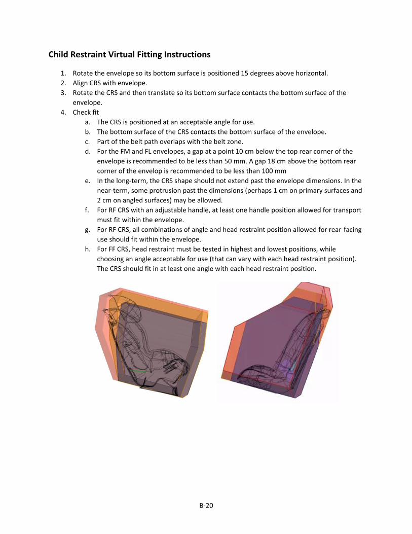
B-20
Child Restraint Virtual Fitting Instructions
1. Rotate the envelope so its bottom surface is positioned 15 degrees above horizontal.
2. Align CRS with envelope.
3. Rotate the CRS and then translate so its bottom surface contacts the bottom surface of the
envelope.
4. Check fit
a. The CRS is positioned at an acceptable angle for use.
b. The bottom surface of the CRS contacts the bottom surface of the envelope.
c. Part of the belt path overlaps with the belt zone.
d. For the FM and FL envelopes, a gap at a point 10 cm below the top rear corner of the
envelope is recommended to be less than 50 mm. A gap 18 cm above the bottom rear
corner of the envelop is recommended to be less than 100 mm
e. In the long-term, the CRS shape should not extend past the envelope dimensions. In the
near-term, some protrusion past the dimensions (perhaps 1 cm on primary surfaces and
2 cm on angled surfaces) may be allowed.
f. For RF CRS with an adjustable handle, at least one handle position allowed for transport
must fit within the envelope.
g. For RF CRS, all combinations of angle and head restraint position allowed for rear-facing
use should fit within the envelope.
h. For FF CRS, head restraint must be tested in highest and lowest positions, while
choosing an angle acceptable for use (that can vary with each head restraint position).
The CRS should fit in at least one angle with each head restraint position.

C-1
APPENDIX C: CRS in Envelopes

C-2
RFCRS
CRS RS RM RL
Baby Trend Flex-Loc no base
Fits
Fits Fits
Baby Trend Flex-Loc with base
Too big
Fits
Fits
Britax B-SAFE No base
Could not achieve angle
Fits
Fits
Britax B-SAFE With base
Too big
Fits
Fits

C-3
CRS RS RM RL
Britax Boulevard CS
Too big
Too wide
Too wide, insufficient bottom contact
Chicco KeyFit no base
Unable to achieve angle
Fits Fits
Chicco KeyFit 30 no base
Unable to achieve angle
Fits; does not meet belt path
Fits; does not meet belt path
Chicco KeyFit with base
Too big
Fits
Fits
Chicco KeyFit 30 With base
Unable to achieve angle, insufficient bottom contact
Too wide
Too wide

C-4
CRS RS RM RL
Compass True Fit (min)
Cannot achieve angle
Angle Insufficient bottom contact
Compass True Fit (max)
Too large
Cannot achieve angle
Insufficient bottom contact
Cosco Comfy Carry no base
Fits
Fits
Fits
Cosco Comfy Carry with base
Too big
Fits
Fits

C-5
CRS RS RM RL
Eddie Bauer Deluxe 3-in-1
Too big Too big
Too wide, insufficient bottom contact
Evenflo Nurture with base
Too big
Fits
Fits
Evenflo Nurture no base
Insufficient bottom contact
Fits
Fits
Evenflo Tribute LX
Unable to achieve angle
Unable to achieve angle
Insufficient bottom contact

C-6
CRS RS RM RL
Evenflo Triumph Advance
Too Big
Too wide, unable to achieve angle
Width
Evenflo Symphony (min)
Too big
Too wide, unable to achieve angle
Fits
Evenflo Symphony (max)
Too big Too big
Fits
Graco Comfort Sport
Too big, insufficient bottom contact
Unable to achieve angle
Unable to achieve angle

C-7
CRS RS RM RL
Graco SnugRide Classic Connect no base
Fits
Fits Fits
Graco SnugRide Classic Connect 35 no base
Fits
Fits
Fits
Graco SnugRide Classic Connect with base
Too big
Fits
Fits
Graco SnugRide Classic Connect 35 with base
Too big
Fits
Fits
Graco My Ride 65
Too big
Fits Fits

C-8
CRS RS RM RL
Maxi-Cosi Prezi with base (max)
Too big
IBC
Fits
Maxi-Cosi Mico With base
Too big
Too big
Fits
Maxi-Cosi Prezi no base (min)
IBC
Angle
Fits
Maxi-Cosi Pria (min)
Could not achieve correct angle
Insufficient bottom contact
Fits

C-9
CRS RS RM RL
Maxi-Cosi Mico No base
Too big
Fits
Fits
Maxi-Cosi Pria (max)
Too big
Fits
Fits
Orbit Baby Toddler Car Seat
Too big
Too Big
Too wide
Peg Perego Primo Viaggio SIP no base
Too big
Insufficient bottom contact
Insufficient bottom contact

C-10
CRS RS RM RL
Peg Perego Primo Viaggio SIP with base
Too big
Too wide
Too wide
Recaro ProRide
Too wide Too Wide
Insufficient bottom contact
Safety 1st Guide 65 Sport min
Fits
Fits Fits
Safety 1st Guide 65 Sport max
Fits
Fits
Fits
Safety 1st Scenera
Could not achieve correct angle
Could not achieve correct angle
Could not achieve correct angle

C-11
CRS RS RM RL
Safety 1st Alpha Omega Elite
Too big
Unable to achieve angle
Insufficient bottom contact, too wide
Sunshine Kids Radian 80SL
IBC IBC
Footprint doesn’t contact base-IBC

C-12
FF CRS
CRS FS FM FL
Eddie Bauer Summit Min
Too Big
Overhang 15.5
Overhang 15.5
Eddie Bauer Summit Max
Too Big Overhang 15.5
Overhang 15.5
Britax Frontier 85 min
IBC Overhang 2
Overhang 2

C-13
CRS FS FM FL
Britax Frontier 85 max
Too big Too Big
LG>100
Orbit Baby Toddler Car Seat
Too big Too big
Overhang 3
Sunshine Kids Radian 80SL
LG> 100 UG>60 Fits
Compass Too big
Fits Fits

C-14
CRS FS FM FL
Britax Boulevard CS min
Too big Too big
LG>100
Britax Boulevard CS, Max
Too big Too big
IBC
Evenflo Triumph Advance Min
Too big
LG>100
LG>100
Evenflo Triumph Advance, max
Too big
LG>100 LG>100

C-15
CRS FS FM FL
Evenflo Symphony min
Too big
Overhang 5.5
Overhang 4.5
Evenflo Symphony max
Too big IBC
Fits
Graco Comfort Sport
Too big
Overhang 4 Overhang 4
Safety 1st
Alpha Omega Elite Min
IBC
Overhang 6.5
Overhang 5.5

C-16
CRS FS FM FL
Safety 1st Alpha Omega Elite Max
Too big
IBC
LG>100
Eddie Bauer Deluxe 3-in-1 min
Too big
Overhang 7.5
Overhang 6
Eddie Bauer Deluxe 3-in-1 max
Too big
IBC LG>100

C-17
CRS FS FM FL
Safety 1st Scenera
Overhang 1.25
Overhang 1.25 Overhang 1.25
Maxi-Cosi Rodi Fix min
LG> 100 Fits
Fits
Maxi-Cosi Rodi Fix max
Too big Too big
LG>100, UPUG UG>50

C-18
CRS FS FM FL
Baby Trend Trendz FastBack 3-in-1
Belt path
Belt path Belt path
Graco Argos 70 min
Overhang 5.5 Overhang 5.5 Overhang 5
Graco Argos 70 max
Too big
Too big
IBC

C-19
CRS FS FM FL
Maxi-Cosi Pria min
IBC Belt path Belt path
Maxi-Cosi Pria max
Too big
IBC
LG>100
Safety 1st Guide 65 Sport
LG>100
LG > 100

C-20
CRS FS FM FL
Safety 1st Guide 65 Sport
LG>100
Fits
Fits
Evenflo Tribute LX
Overhang 4 Overhang 4 Overhang 4
Graco My Ride 65
Too big
Too big Fits

C-21
CRS FS FM FL
Recaro ProRide
Too big
Too big
LG>100
The First Years True Fit SI
Too big
Too big
LG>100

D-1
Appendix D: Envelopes in Vehicles

D-2
Fit Chevrolet Cruze
RS √
RM FSI
RL FSI, LCI

D-3
Fit Ford Escape
RS √
RM √
RL FSI

D-4
Fit Honda Pilot
RS √
RM √
RL FSI

D-5
Fit Hyundai Elantra
RS √
RM √
RL FSI, LCI

D-6
Fit Toyota Camry
RS √
RM √
RL FSI

D-7
Fit Toyota Sienna (revised envelopes)
RS √
RM √
RL √

D-8
Fit Ford Escape
FS √
FM √
FL √

D-9
Fit Ford Focus
FS √
FM √
FL LCI

D-10
Fit Hyundai Elantra
FS √
FM √
FL √

D-11
Fit Nissan Sentra
FS √
FM √
FL LCI

D-12
Fit Subaru Outback
FS √
FM √
FL √

D-13
Fit Toyota Sienna
FS √
FM √
FL √

DOT HS 812 610
September 2018
13666-091918-v2a


![Stephen Briggs [Compatibility Mode]](https://static.fdokumen.com/doc/165x107/6324c3005c2c3bbfa802dd10/stephen-briggs-compatibility-mode.jpg)

![Ruth Knight presentation.ppt [Compatibility Mode]](https://static.fdokumen.com/doc/165x107/631d5d013ba403638902baaf/ruth-knight-presentationppt-compatibility-mode.jpg)


![kkt_6_dan_7_pemupukan_2014 [Compatibility Mode]](https://static.fdokumen.com/doc/165x107/6322b43c28c445989105e2db/kkt6dan7pemupukan2014-compatibility-mode.jpg)