DEVELOPMENT OF EXPERIMENTAL SELF ...
81
Tallinn 2019 TALLINN UNIVERSITY OF TECHNOLOGY School of Information Technologies Juri Šatov 143654IVEM DEVELOPMENT OF EXPERIMENTAL SELF-CHOREOGRAPHED DANCING FOUNTAIN Master’s thesis Supervisor: Eero Haldre Dipl. Eng.
-
Upload
khangminh22 -
Category
Documents
-
view
2 -
download
0
Transcript of DEVELOPMENT OF EXPERIMENTAL SELF ...

Tallinn 2019
TALLINN UNIVERSITY OF TECHNOLOGY
School of Information Technologies
Juri Šatov 143654IVEM
DEVELOPMENT OF EXPERIMENTAL
SELF-CHOREOGRAPHED DANCING
FOUNTAIN
Master’s thesis
Supervisor: Eero Haldre
Dipl. Eng.

Tallinn 2019
TALLINNA TEHNIKAÜLIKOOL
Infotehnoloogia teaduskond
Juri Šatov 143654IVEM
EKSPERIMENTAALSE ISESEADISTAVA
TANTSUGA PURSKKAEVU ARENDAMINE
Magistritöö
Juhendaja: Eero Haldre
Dipl. Ins.

3
Author’s declaration of originality
I hereby certify that I am the sole author of this thesis. All the used materials, references
to the literature and the work of others have been referred to. This thesis has not been
presented for examination anywhere else.
Author: Juri Šatov
06.05.2019
4
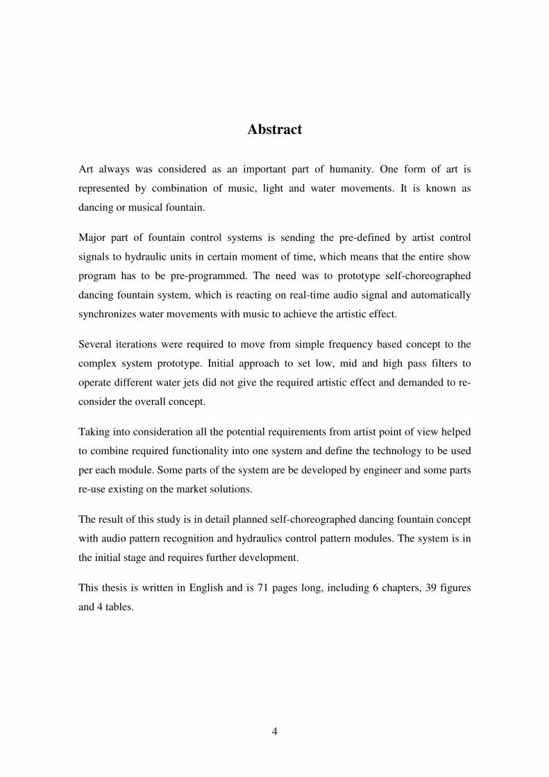
Abstract
Art always was considered as an important part of humanity. One form of art is
represented by combination of music, light and water movements. It is known as
dancing or musical fountain.
Major part of fountain control systems is sending the pre-defined by artist control
signals to hydraulic units in certain moment of time, which means that the entire show
program has to be pre-programmed. The need was to prototype self-choreographed
dancing fountain system, which is reacting on real-time audio signal and automatically
synchronizes water movements with music to achieve the artistic effect.
Several iterations were required to move from simple frequency based concept to the
complex system prototype. Initial approach to set low, mid and high pass filters to
operate different water jets did not give the required artistic effect and demanded to re-
consider the overall concept.
Taking into consideration all the potential requirements from artist point of view helped
to combine required functionality into one system and define the technology to be used
per each module. Some parts of the system are be developed by engineer and some parts
re-use existing on the market solutions.
The result of this study is in detail planned self-choreographed dancing fountain concept
with audio pattern recognition and hydraulics control pattern modules. The system is in
the initial stage and requires further development.
This thesis is written in English and is 71 pages long, including 6 chapters, 39 figures
and 4 tables.

5
Annotatsioon
Eksperimentaalse iseseadistava tantsuga purskkaevu
arendamine
Kunsti on alati loetud inimkonna tähtsaks osaks. Üks kunsti vorm on esindatud
muusika, valgustuse ja vee koreograafia kombinatsiooni poolt. Seda tuntakse kui
tantsiva või muusikalise purskkaevuna.
Põhiline osa purskkaevu juhtsüsteemist saadab kindlatel ajahetkedel kunstniku poolt
eelmääratud juhtsignaale hüdraulika moodulitesse, mis tähendab, et kogu vaatemäng
peab olema eelprogrammeeritud. Vajadus oli prototüüpida iseseadistava tantsuga
purskkaevu süsteem, mis reageeriks reaalajas helisignaalile ja sünkroniseeriks
automaatselt vee liikumise selle järgi, et saavutada kunstilist efekti.
Vaja läks mitu iteratsiooni, et liikuda lihtsa helisageduste põhise kontseptsiooni pealt
keerulisema prototüüp süsteemi peale. Algne lähenemine seada madal-, kesk- ja
kõrgheli filtrid juhtima erinevaid veejugasid ei andnud nõutud kunstilist efekti ja vajas
üldise kontseptsiooni ümber mõtlemist.
Kõikide võimalike nõudmiste ja kunstniku vaatenurga arvesse võtmine aitas
kombineerida vajaliku funktsionaalsuse ühe süsteemi ja defineerida tehnoloogiad mida
kasutada erinevate moodulite jaoks. Mõned süsteemiosad arendatakse välja inseneri
poolt ja mõnede puhul taaskasutatakse juba turul olemasolevaid lahendusi.
Selle uurimuse tulemuseks on iseseadistava tantsuga purskkaevu kontseptsioon koos
helimustri tuvastus ja hüdraulikamustri juhtmoodulitega. Süsteem on algfaasis ja vajab
edasist arendamist.
Lõputöö on kirjutatud inglise keeles ning sisaldab teksti 71 leheküljel, 6 peatükki, 39
joonist, 4 tabelit.
6
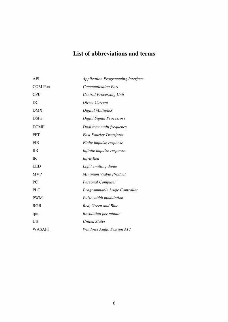
List of abbreviations and terms
API Application Programming Interface
COM Port Communication Port
CPU Central Processing Unit
DC Direct Current
DMX Digital MultipleX
DSPs Digial Signal Processors
DTMF Dual tone multi frequency
FFT Fast Fourier Transform
FIR Finite impulse response
IIR Infinite impulse response
IR Infra-Red
LED Light emitting diode
MVP Minimum Viable Product
PC Personal Computer
PLC Programmable Logic Controller
PWM Pulse-width modulation
RGB Red, Green and Blue
rpm Revolution per minute
US United States
WASAPI Windows Audio Session API

7
Table of contents
1 Introduction ................................................................................................................. 12
1.1 Fountains Progress timeline.................................................................................. 13
1.2 Current situation on the Market ............................................................................ 14
1.2.1 Most common installation ............................................................................. 14
1.3 What is the need? .................................................................................................. 17
2 Pre-requirements / Preparations .................................................................................. 19
2.1 Hydraulics parts .................................................................................................... 20
2.2 Electronics Parts ................................................................................................... 22
2.3 Hydraulics Test Model ......................................................................................... 25
2.4 Preparation tests .................................................................................................... 26
2.4.1 Water jet delay ............................................................................................... 26
2.4.2 Electronic / Solenoid Valve ........................................................................... 30
2.5 Preparation results ................................................................................................ 31
3 Light Organ approach .................................................................................................. 31
3.1 Microphone & Arduino: Volume application ...................................................... 32
3.1.1 Program and Simulation ................................................................................ 33
3.1.2 Real-model tests ............................................................................................ 33
3.2 Matlab & Arduino: Filters .................................................................................... 34
3.2.1 Matlab: real-time audio ................................................................................. 35
3.2.2 Matlab: Filters ............................................................................................... 36
3.3 Light Organ approach outcome ............................................................................ 38
4 Experimental Self-Choreographed Dancing Fountain Concept .................................. 39
4.1 Artist’s point of view ............................................................................................ 40
4.2 Fountain Behavior Configurator ........................................................................... 41
4.2.1 Audio Signal Patterns .................................................................................... 42
4.2.2 Controls Signals patterns ............................................................................... 48
4.2.3 Audio And Control patterns matching .......................................................... 50
4.3 Dancing Fountain Control system ........................................................................ 51
4.3.1 Validation block ............................................................................................ 51
4.3.2 Control Signals technology ........................................................................... 53
4.4 Outcome................................................................................................................ 53

8
4.4.1 Dancing Fountain Control system concept .................................................... 53
5 Prototyping .................................................................................................................. 55
5.1 Audio receiver ...................................................................................................... 56
5.1.1 Bass.dll library ............................................................................................... 56
5.2 Audio Pattern recognition ..................................................................................... 58
5.2.1 Algorithms / Functions technology ............................................................... 58
5.2.2 Fingerprinting technology ............................................................................. 59
5.2.3 Machine learning technology ........................................................................ 61
5.3 Control pattern configuration ............................................................................... 62
5.4 Validations & Hydraulics Control ........................................................................ 63
5.4.1 Validations ..................................................................................................... 63
5.4.2 Hydraulic Control .......................................................................................... 63
5.5 Hydraulic Units..................................................................................................... 64
5.6 Simulator & tester ................................................................................................. 64
5.7 Prototyping outcome............................................................................................. 66
6 Summary ...................................................................................................................... 67
References ...................................................................................................................... 69
Appendix 1 – [Arduino codes] ....................................................................................... 72
Appendix 2 – [Matlab Code] .......................................................................................... 74
Appendix 3 – [Fountain Simulator] ................................................................................ 76
Appendix 4 – [Simulator to Arduino Connection] ......................................................... 78
9
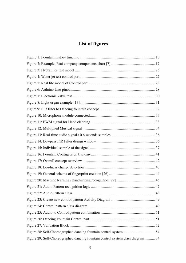
List of figures
Figure 1: Fountain history timeline ................................................................................ 13
Figure 2: Example. Paai company components chart [7] ............................................... 17
Figure 3: Hydraulics test model ..................................................................................... 25
Figure 4: Water jet test control part ................................................................................ 27
Figure 5: Real life model of Control part ....................................................................... 28
Figure 6: Arduino Uno pinout ........................................................................................ 28
Figure 7: Electronic valve test ........................................................................................ 30
Figure 8: Light organ example [13] ................................................................................ 31
Figure 9: FIR filter to Dancing fountain concept ........................................................... 32
Figure 10: Microphone module connected ..................................................................... 33
Figure 11: PWM signal for Hand clapping .................................................................... 33
Figure 12: Multiplied Musical signal ............................................................................. 34
Figure 13: Real-time audio signal / 0.6 seconds samples ............................................... 36
Figure 14: Lowpass FIR Filter design window .............................................................. 36
Figure 15: Individual sample of the signal ..................................................................... 37
Figure 16: Fountain Configurator Use case .................................................................... 41
Figure 17: Overall concept overview ............................................................................. 42
Figure 18: Loudness change detection ........................................................................... 43
Figure 19: General schema of fingerprint creation [26] ................................................. 44
Figure 20: Machine learning / handwriting recognition [29] ......................................... 45
Figure 21: Audio Pattern recognition logic .................................................................... 47
Figure 22: Audio Pattern class........................................................................................ 48
Figure 23: Create new control pattern Activity Diagram ............................................... 49
Figure 24: Control pattern class diagram ....................................................................... 49
Figure 25: Audio to Control pattern combination .......................................................... 51
Figure 26: Dancing Fountain Control part ..................................................................... 51
Figure 27: Validation Block ........................................................................................... 52
Figure 28: Self-Choreographed dancing fountain control system .................................. 54
Figure 29: Self-Choreographed dancing fountain control system class diagram ........... 54

10
Figure 30: Self-Choreographed dancing fountain control system development ............ 55
Figure 31: Bass.dll application examples [24] ............................................................... 57
Figure 32: Loudness difference pattern logic ................................................................. 59
Figure 33: 30 seconds long non-overlapping spectrogram cut at 318-2000Hz frequency
range [34] ........................................................................................................................ 60
Figure 34: Pattern Configurator window ........................................................................ 63
Figure 35: Dancing Fountain Simulator ......................................................................... 65
Figure 36: Fountain Simulation Software interface ....................................................... 66
Figure 37: Audio Spectrum Analyser example .............................................................. 76
Figure 38: SerialPort object configuration ..................................................................... 78
Figure 39: Fountain Simulation Software interface ....................................................... 79

11
List of tables
Table 1: L298N Motor Driver control logic ................................................................... 29
Table 2: Hydraulics Unit parameters .............................................................................. 50
Table 3: Control Pattern parameters ............................................................................... 50
Table 4: BassWasapi.BASS_WASAPI_GetData Method parameters ........................... 57

12
1 Introduction
Cambridge dictionary says:
Fountain - a stream of water that is forced up into the air through a small hole,
especially for decorative effect, or the structure in a lake or pool from which this flows.
[1]
Fountains always were considered as Art objects and it was inevitable that someone
took this one art object and combined it with another one – the Music.
First musical fountain was created in 19th century and was operated by hydraulic
means. Small bells were playing the music while the river was rotating the watermill.
Since that time the technology has evolved a lot and gave us the opportunity to create
more and more technologically advanced systems. Fountains are not an exception.
Musical fountains were replaced by dancing fountains.
Dancing fountain (also known as Musical fountain) is a type of animated fountains for
entertainment purposes. The movements of water jets are synchronized with music to
achieve the artistic effect.
Early dancing fountains required an operator to control the jets, lightning and music,
which means, that the person was listening the music and at the same time pressing the
buttons to control all the equipment.
Step by step human interface was replaced by electronic circuits, but the main progress
in dancing fountain automation was achieved in early 80th with help of Programmable
Logic Controllers. PLCs were able to pre-program all the required signals to control the
hydraulics part.
The programming of PLCs were easy and cheap comparing to creation of specific
electronic circuit for different songs. Many fountains over the world were re-designed to
be able to use automatic controllers.

13
These days we have a huge variety of dancing fountains. Installation could be whether
really big, like 36000 square meters of Bellagio fountains, or small enough to fit into the
backyard. Cost of installation also depends on its complexity and can go up to 100
million euros.
Almost all modern fountains are fully automated and running the pre-programmed
shows many times a day.
The key point of the previous sentence is “pre-programmed”, which means that all the
control signals are pre-defined by human.
There are also some developments in the market for “self-choreographed" real-time
fountains, what can react to random musical input. Such a fountains and especially the
control algorithm is the main focus of this Master’s thesis.
1.1 Fountains Progress timeline
• 1820-1822 - First musical fountain. Built by Peter Bodor in the
Transylvanian town of Marosvásárhely (now Târgu Mureş, Romania)
Operated by hydraulic means.
• 1891 - Křižík's fountain. Built by František Křižík in 1891 on the occasion of
the World Exhibition. The bottom of the fountain plate is equipped with
1300 multicolored reflectors and water circuits composed of more than 2
kilometers of pipes with almost 3000 nozzles.
• 1909 - Prismatic Fountain, Denver, Colorado. Eleven columns of brightly
colored light stream through the dramatic changing patterns of water. F.W.
Figure 1: Fountain history timeline
14
Darlington was a pioneer in electrical fountain control as well as water
design. Fountain required an operator to change the water effects and
lighting
• 1929 - The Magic Fountain of Montjuïc, Barcelona. In the 1980s, an element
of music was incorporated to the fountain’s light show, which now appears
to perform to the rhythm of song
• 1980 – The revolution has started mainly in US. Fully automated Dancing
fountains started to appear.
• 1998 - Fountains of Bellagio. Largest at that time. More than 1,200 nozzles
that make it possible to stage fountain displays coordinated with more than
4,500 lights. It is estimated that the fountains cost $40 million to build.
• 2009 - The Dubai Fountain. Largest fountain in the world. USD $218
million
• 2012 - India’s most spectacular musical fountain – the CESC Fountain of
Joy – was inaugurated in Kolkata.
Quite many musical fountains, what we can observe now, were created in mid or early
ages of 20th century. Most of them were lacking musical or lightning part in the
beginning and were redesigned already at the end of 20th century.
1.2 Current situation on the Market
Almost all dancing fountains in the world, and especially the most famous ones, are
using pre-programmed style of choreography for dancing fountains.
There are many dancing fountain control systems in the market, but most of them are
proprietary development. There is no common standard on the market.
1.2.1 Most common installation
Even if there is no common standard in the Dancing fountain market, the components of
the system are more or less the same from one system to another.

15
Most common installation for dancing fountains includes:
PumpPumpPumpPump
Pump can be submersible or external.
Submersible pumps are used when the whole assembly is submerged into the fluid
(water in our case) to be pumped. They push fluid to the surface. Such pumps are
usually used when dancing fountain is a temporary construction and has to be built
inside the pool or pound. Floating dancing fountains are also using submersible pumps.
External of jet pump is assembled outside of the fluid source and pulling fluids through
the pipes. External pumps are usually used in the permanent setups and require more
complex piping network.
The choice of the pump varies from one application to another.
Different Pump motor drivers are in use to control the motor speed, which allows
controlling the water jet height.
NozzlesNozzlesNozzlesNozzles
Nozzles are connected to the pipes and can modify the jet qualities, such as shape
thickness. They can make foamy water or split it into mane small jets.
These days technology allows creating Digital Nozzles with 2 or 3 dimensional rotating
possibilities. Digital nozzles allow controlling the direction of each individual water jet
and increasing the water dancing effect.
Digital Nozzles is an interesting topic for research, but it is out of scope in this Master’s
thesis.
Electronic ValvesElectronic ValvesElectronic ValvesElectronic Valves
The main role of the valve is to block water flow in each individual nozzle or the whole
pipe. Electronic valves can be controlled by the electric signal, which allows pre-
programming their behavior.
ControllersControllersControllersControllers

16
Controllers are used to send the re-defined signals in time to control all the equipment:
pumps (via motor drivers), Digital nozzles, Electronic valves, Light etc.
PLCs were the most common application during the long time, but now it is more and
more replaced by DMX controllers.
DMX technology (actually the name is DMX512, but usually it is shortened) is an
electronic protocol used in lighting technologies to control shows lighting, allowing
communication between the lights control equipment and light sources. [10]
DMX is usually used in more complex projects with a lot of components used
independently and PLC is still used in projects with a physical grouping of common
elements.
ComputerComputerComputerComputer with with with with Fountain control Fountain control Fountain control Fountain control softwaresoftwaresoftwaresoftware
It is the main point of interest in frames of this Master’s thesis. Usually the controllers
are programmed with specific software. Almost every major company in Dancing
Fountain market is using their proprietary systems.
Specific software allows for Artist to define the fountain movement in time domain to
synchronize them with the specific song. This software transforms the Artist’s vision
into the signals required to control every part of the system and saves this “program” to
the Controller.
In some cases signals are not saved on the controllers but information is send to
Controller from the computer in real-time and Controller forward this signals to the
relevant component.
LightsLightsLightsLights
Also Video or Laser projector, RGB LEDs or movable head Lamps can be used to
increase the artistic effect.
Here is the example for the usual Dancing fountain setup from Paai Company:

17
Figure 2: Example. Paai company components chart [7]
Our days almost all musical fountains have similar components and even if technology
is different, the approach is more or less the same.
• Almost 100% of dancing fountains are pre-choreographed, which means that all
control signals are pre-defined. Not real-time.
• Almost 100% of dancing fountains are big or even huge, so they are not
applicable for in-house use in small rooms or in apartments.
Only few companies are developing self-choreographed dancing fountain systems these
days. Most successful is H2OArts (www.h20arts.com). They have couple of
commercial implementations already, but, of course, we are talking about really small
fountains comparing to the leaders on the market.
1.3 What is the need?
It is true, that more and more cities, casinos, shopping malls are interesting in installing
different versions of dancing fountains on their premises to attract more people. At the
same time ordinary people are also interested in decoration their back yards and dancing
fountains could be a good option to impress guests.
What about small restaurants or even apartments? We can have dancing fountains there
as well, but the specifications for such a fountains are already different than the other
ones.
18
It has to be:
• Standalone product, which is easy to deploy.
• Size is not bigger than 1 m2.
• The cost is also matters and it can be reduced by using less powerful and
cheaper components: pumps, motor drives and electronics controllers.
The main thing, this Dancing fountain has to be able adjusting the “Show program” in
real-time. There is no option that someone will pre-program every water jet for all the
songs playing out of the loudspeakers. So, it would be reasonable to implement the
technology to avoid human interaction in pre-programming.
It is necessary to design the control system for musical fountain which meets the
following requirements:
• Able to read the signal (Musical signal in my use case, but it can be any other
signal) from external environment. Use of microphone.
• Analyze this signal in real-time.
• Send control signals to motor drives and electronic valves.
Other words, the Dancing fountain control system has to be self-choreographed.
The ultimate goal is to build the full system with the criteria described above, but the
main focus of this Master’s thesis is the research and tests of the best appropriate
algorithm to be used in self-choreographed dancing fountain.
Also, for now the exact control signals to all the components will be based on pre-
defined hydraulics part, but they are not final, because hydraulics part most probably
will be changed in final application. What is more important is to understand how to
analyze the incoming sound signal and what water behavior has to follow after this
analysis.

19
2 Pre-requirements / Preparations
Despite the fact that I am focusing on research and analysis of best possible algorithm
required to build the self-choreographed dancing fountain, it is necessary to define the
hydraulics and electronics parts and perform some tests first.
I have to define the hydraulics parts to know what signals I have to send to control
them. Even if the component brands or models will be changed in future, the common
approach will stay the same or similar to current one.
Combination of Hydraulics and Electronics parts is the toolbox and the environment for
testing the self-choreographed algorithms.
It doesn’t necessarily mean that same hydraulics or electronics parts will stay in final
product. For now it just represents the minimum requirements to start the control
algorithm development and testing.
Even if the main goal of this Master’s thesis not to build the fully operational system,
the initial idea is not simply to define the components, but also purchase them for
testing purposes. There are too many uncertainties with this project and real life testing
will help to eliminate or minimize these uncertainties.
Please also note that the choice of fountain parts is not final and contains a lot of
compromises in respect of price/quality combination.
Selection of proper components for production system is a topic for another case study.

20
2.1 Hydraulics parts
Submersible pumpSubmersible pumpSubmersible pumpSubmersible pump:::: JTJTJTJT----500500500500----12V12V12V12V Water pump to be used to pump the water and create the water jet. One pump is used
per one set of Nozzles. It can be just one or plenty of nozzles (holes) controlled by one
Water pump.
Specifications:
• Size:105mm(height)*38mm(diameter) • Water Outlet Outer Diameter:12mm
• Water Outlet Inner Diameter:9.7mm
• Rated Voltage: 12V
• Working Voltage: 6-12V (Maximum 15V)
• Rated Current: 1.2A
• Maximum Lift: 5M
• Maximum Flow Rate: 60 0L/Hour • Cable: Three core
• Cable Length: 1.5m
Wire Connection:
1. Brown cable connects the Positive Pole "+"
2. Blue cable connects Negative Pole "-"
3. Yellow cable is GND, don't need to connect.
Important Information: The temperature of the water cannot be over 40 degree.
Seller has indicated one important point about this pump: “This is the brush pump, so it
cannot be used continuously, or the lifespan of the pump will be short. Suggest relaxing
1 hour after using 2 hours to extend the lifespan of the pump.”
This information clearly states that this pump can’t be used in dancing fountain system,
but quite Ok for testing purposes.

21
G1/2" Plastic electronic valveG1/2" Plastic electronic valveG1/2" Plastic electronic valveG1/2" Plastic electronic valve
Blocks the output of water for the pipe or for the individual nozzle until the proper
signal is send. Electronic valve is closed until the voltage is applied.
Specifications:
• Use fluid: Water • Type: Normally closed • Voltage: AC220V DC12V
DC24V • Size: G1/2" • Pressure range: 0.02 ~ 0.6mpa • Temperature range: 0 ~ 80 °
Pipes and Pipe JointsPipes and Pipe JointsPipes and Pipe JointsPipes and Pipe Joints Pipes and pipe joints will be used in hydraulics part of test model. This is something
what is not related to electronics or control system part, but you can’t ignore it while
working on any of Dancing fountain subsystems.
Specifications:
• Pipe size: D12/16 mm • Joint size: 16mm

22
2.2 Electronics Parts
Arduino UnoArduino UnoArduino UnoArduino Uno Arduino’s main role is to control the Hydraulics part with PWM signal.
Level of Signal processing logic on the microcontroller was changing during the
research process.
Specifications:
• Microcontroller: ATmega328P • Operating Voltage: 5V • Input Voltage (recommended): 7-12V • Input Voltage (limit): 6-20V • Digital I/O Pins: 14 (of which 6 provide PWM
output) • PWM Digital I/O Pins: 6 • Analog Input Pins: 6 • DC Current per I/O Pin: 20 mA • DC Current for 3.3V Pin: 50 mA • Flash Memory: 32 KB (ATmega328P) of
which 0.5 KB used by bootloader • SRAM: 2 KB (ATmega328P) • EEPROM: 1 KB (ATmega328P) • Clock Speed: 16 MHz • LED_BUILTIN: 13 • Length: 68.6 mm • Width: 53.4 mm • Weight: 25 g
Important Information:
Arduino Uno Board was chosen as test environment for 2 reasons:
1. Big variety of libraries. Way easier to get the working prototype than
with other Launchpad’s.
2. I already had it in my “Electronics box”.
It will be replaced in production environment. Not powerful enough for
Signal processing

23
Motor driver with L298N chip, HMotor driver with L298N chip, HMotor driver with L298N chip, HMotor driver with L298N chip, H----Bridge, PWMBridge, PWMBridge, PWMBridge, PWM Motor driver controls the speed of DC motor in the Water pump, which follows with
changes of the water jet height.
Specifications:
• Work mode: H bridge drive (double) • Main control chip: L298N • Logical voltage: 5V • Drive voltage: 5v-35v • Logical current: 0mA-36mA • Driving current: 2A (MAX single bridge) • Storage temperature: - 20 ℃ to + 135 ℃ • Maximum power: 25W • Weight: 30 g • Peripheral dimensions : 43*43*27m
Important Information:
1. When driving voltage is less than 12V, on-board 5V power supply can be used
to power the Microcontroller or other board.
2. When the driving voltage is higher than 12V, 5V power supply can’t be used.
Use board jumper to control these modes.
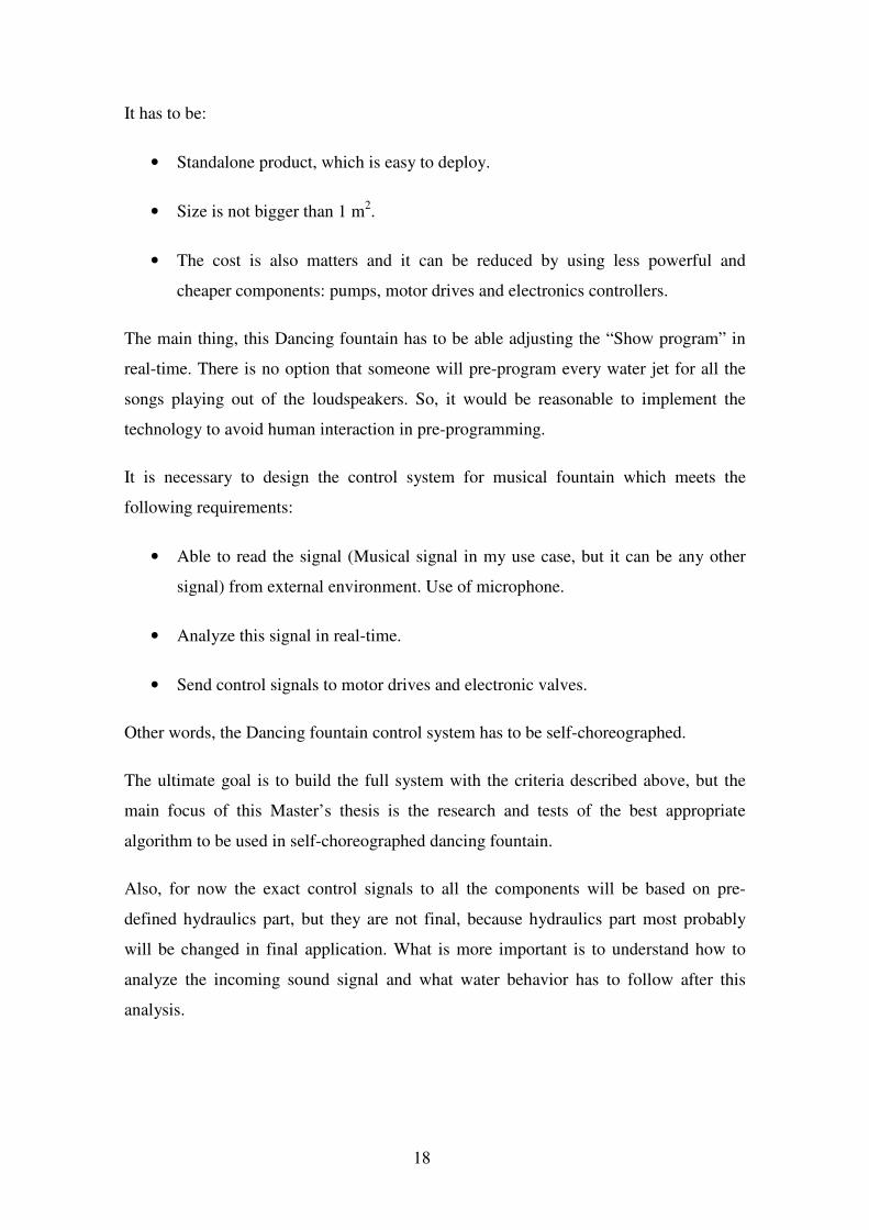
Arduino Microphone ModuleArduino Microphone ModuleArduino Microphone ModuleArduino Microphone Module Electret microphone with amplifier on-board. To be used for sound detection.
Specifications:
• Voltage : 3.3v to 5v • Differential Comparator : LM393 • Microphone : Electret condenser • Size : 45mm x 17mm x 10mm (length x width x
height)
24
Connection to Arduino
1. Pin + to Arduino 5+
2. Pin - to Arduino -
3. Pin A0 to Arduino A0 (for analog program)
4. Pin D0 to Arduino 13 (for digital program)
Important Information:
This module has configurable sound level.
• The sound level setpoint is adjusted via an on-board potentiometer clockwise
more sensitive and counter clockwise less sensitive.
• When the sound level exceeds the set point, LED on the module is illuminated
and the output is sent low.
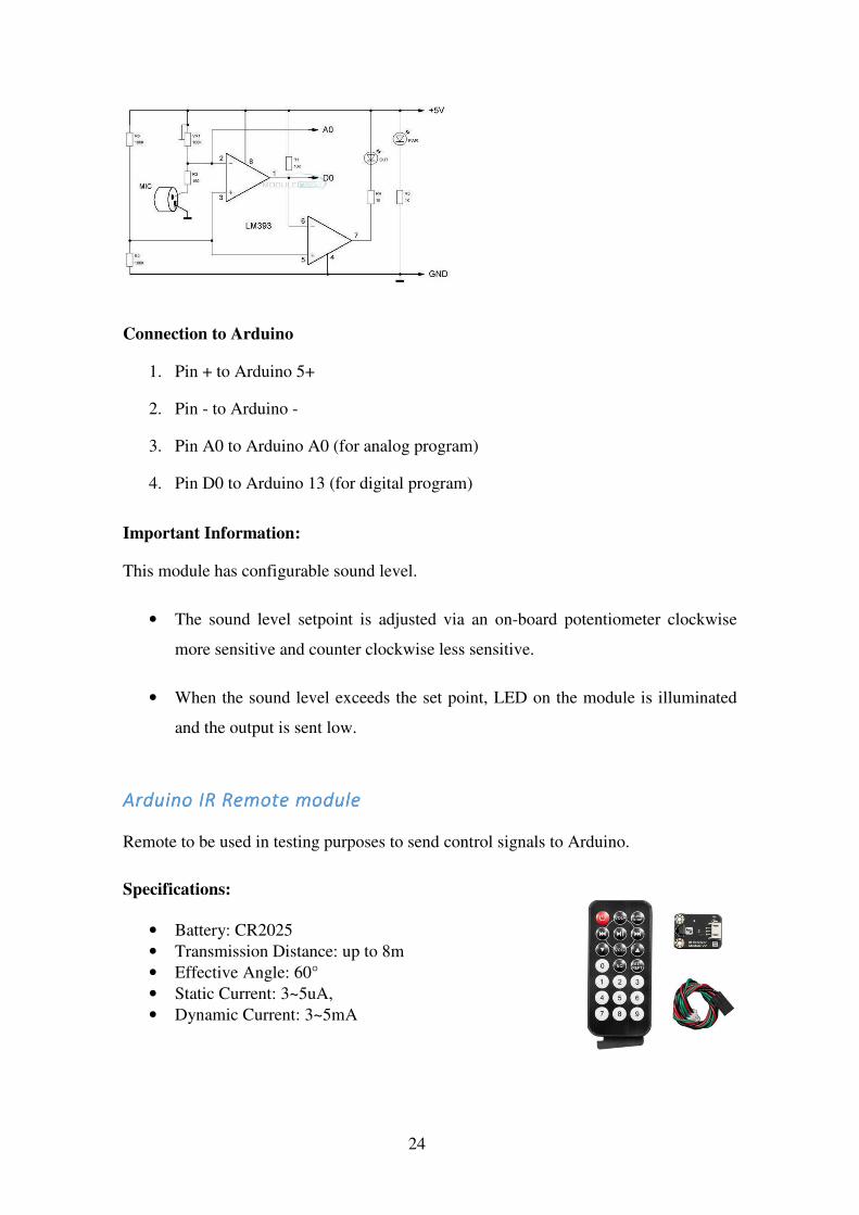
Arduino IR Remote moduleArduino IR Remote moduleArduino IR Remote moduleArduino IR Remote module Remote to be used in testing purposes to send control signals to Arduino.
Specifications:
• Battery: CR2025 • Transmission Distance: up to 8m • Effective Angle: 60° • Static Current: 3~5uA, • Dynamic Current: 3~5mA

25
RelayRelayRelayRelay
Power electronics can’t be controlled directly from low voltage Arduino pins. This relay
will be connected to Electronic Valve and to be controlled by Arduino. When control
signal is applied and relay is on – the Electronic Valve will get the power signal then.
Specifications:
• Max Voltage: 12V • Control signal: 3-
5V • Channels: 2
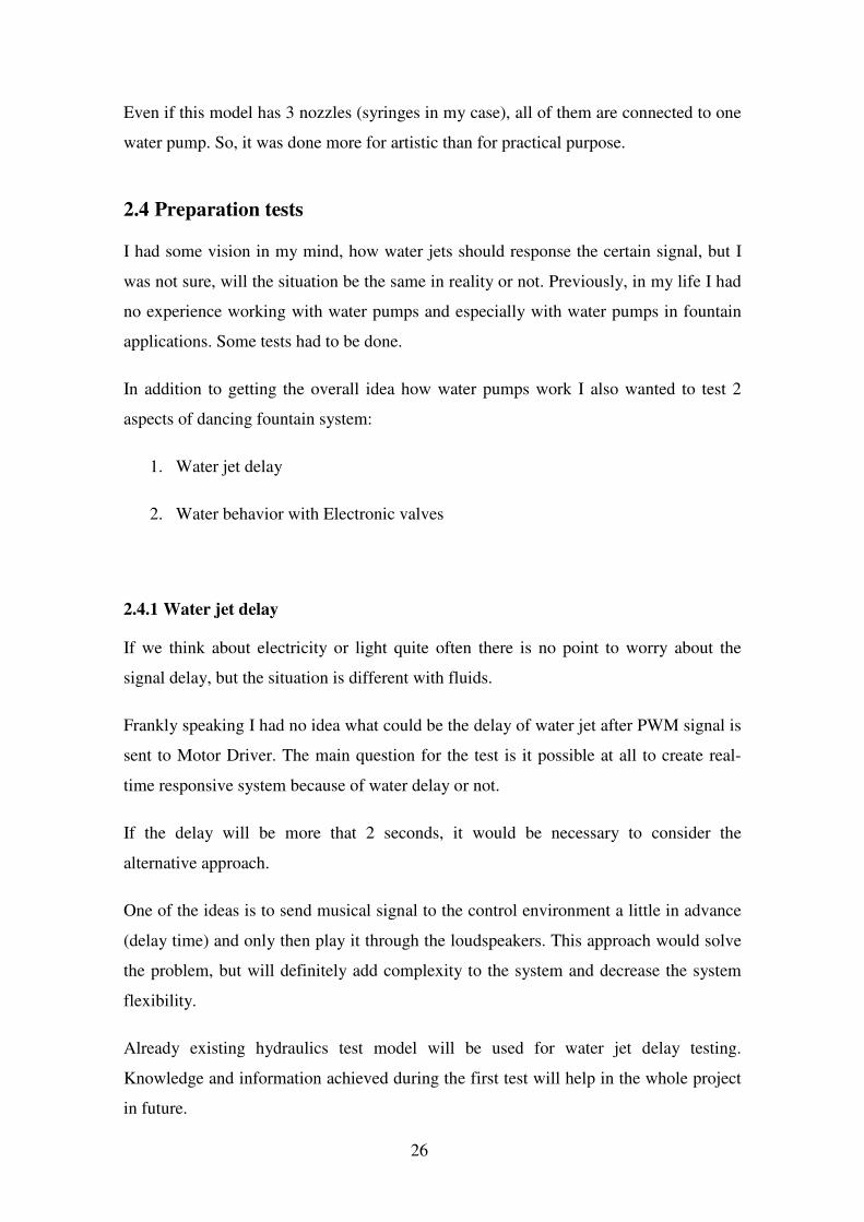
2.3 Hydraulics Test Model
As I have mentioned before, building the real life model of dancing fountain is out of
scope for this Master’s thesis, but before starting the algorithm development it was
necessary to define hydraulics and electronics parts and also run couple tests understand
the water behavior and eliminate the uncertainties.
The following model of fountain hydraulics part was created:
Figure 3: Hydraulics test model
26
Even if this model has 3 nozzles (syringes in my case), all of them are connected to one
water pump. So, it was done more for artistic than for practical purpose.
2.4 Preparation tests
I had some vision in my mind, how water jets should response the certain signal, but I
was not sure, will the situation be the same in reality or not. Previously, in my life I had
no experience working with water pumps and especially with water pumps in fountain
applications. Some tests had to be done.
In addition to getting the overall idea how water pumps work I also wanted to test 2
aspects of dancing fountain system:
1. Water jet delay
2. Water behavior with Electronic valves
2.4.1 Water jet delay
If we think about electricity or light quite often there is no point to worry about the
signal delay, but the situation is different with fluids.
Frankly speaking I had no idea what could be the delay of water jet after PWM signal is
sent to Motor Driver. The main question for the test is it possible at all to create real-
time responsive system because of water delay or not.
If the delay will be more that 2 seconds, it would be necessary to consider the
alternative approach.
One of the ideas is to send musical signal to the control environment a little in advance
(delay time) and only then play it through the loudspeakers. This approach would solve
the problem, but will definitely add complexity to the system and decrease the system
flexibility.
Already existing hydraulics test model will be used for water jet delay testing.
Knowledge and information achieved during the first test will help in the whole project
in future.

27
The Electronics (control) part presented below:
The control part of my test environment contains:
1. Arduino Uno as a central unis. It processes the received signals and sends
signals to control the hydraulics part
2. Motor driver controls the speed of water pump motor. Controlled by PWM
signal from Arduino.
3. IR transmitter/receiver combination is programmed to control the PWM signal
from Arduino.
4. 12V Power supply is used to power the water pump motor and motor driver
5. Submersible Water pump pushes the water
Figure 4: Water jet test control part

28
Arduino Uno can write an analog value (PWM wave) to a pin. Supported pins: 3, 5, 6,
9, 10, and 11.
Figure 6: Arduino Uno pinout
PWM signal can be used to light a LED with different brightness or drive a motor with
different speed. After a call to analogWrite(), the pin will generate a steady square wave
of the specified duty cycle until the next call to analogWrite().
Syntax: analogWrite(pin, value)
Parameters: pin: the pin to write to. Allowed data types: int. value: the duty cycle:
between 0 (always off) and 255 (always on). Allowed data types: int [12]
Figure 5: Real life model of Control part

29
From the documentation we can see that the range of analogWrite() value is from 0 to
255.
I’ve programmed the IR remote buttons 1, 2 and 3 to change Arduino Uno PWM signal
on pin 5 to 100, 150 and 200 accordingly.
int speed;
…
//Speed control
if (results.value == 16599223) speed = 100; // Button 3
if (results.value == 16591063) speed = 150; // Button 4
if (results.value == 16623703) speed = 200; // Button 5
…
analogWrite(EnB, speed);
Also I’ve added the Motor turn on and turn off logic as described on the table below:
Table 1: L298N Motor Driver control logic
Input 1 Input 2 Result
LOW HIGH Move Forward
HIGH LOW Move Backward
LOW LOW Motor Stop
HIGH HIGH Motor Stop
// Turn ON motor
if (results.value == 16593103) { // Button 0
digitalWrite(In3, LOW);
digitalWrite(In4, HIGH);
speed = 100;
}
Please see the full code in Appendix 1.
After all the installation was done and Program code was loaded into Arduino I was
able successfully run the test.
Test Outcome:Test Outcome:Test Outcome:Test Outcome:

30
Water jet delay was really small. Less than half a second. It was not visible for human
eye. The height of the water jet was changing right after clicking the button on the
remote. The result is good and allows moving on with the initial idea: system will read
and analyze the sound signal real-time.
2.4.2 Electronic / Solenoid Valve
To perform this test it was necessary to modify the hydraulics part of my test
environment. Electronic valve was added to the circuit. Expected behavior is to have the
water shoots out of the nozzle when valve is open for one second or less.
I’ve decided not to create the complex systems, but just to connect 12V DC power to
Electronic Valve with ON/OFF switch. After starting the water pump, I’ve just played
with the switch and observer the result.
Test Outcome:
The test has failed: For some reason the water jet height was too low. Almost no jet, just
slowly flowing water.
I don’t think that the problem is with electronic valve, because I heard the ‘Clicks’ when
12V voltage was applied and water started to flow. Most probably the pump is not
powerful enough to push the water through the Valve.
Anyway, I decided not to spend a lot of time to solve this problem, but just to eliminate
the Electronic valve from my fountain system for now. Such valves with the expected
water behavior will definitely add the artistic value to the system, but hydraulics part is
Figure 7: Electronic valve test

31
not the main goal for this Master’s thesis. Secondly, when the control logic is defined, it
is planned to extend the hydraulics part not only with electronic valves but with
electronic nozzles as well.
2.5 Preparation results
For now we have:
- Suitable for our application water delay after sending the control PWM signal.
- Physical test model to perform the tests of water jet behavior
- Knowledge acquired during the preparation tests is a good starting point.
After all the preparations and tests are done, it is possible to move on with the main
topic – self-choreographed dancing fountain control logic.
3 Light Organ approach
The idea is to use Light organ approach in dancing fountain application.
Light organ is a device which separates the musical spectrum into frequency bands
(called channels) and blinks the lamps in time with the music. Usually music is
separated into low, mid, and high frequency bands (sometimes even more) and one or
many colored lamps are driven from each channel – usually red for the high
frequencies, yellow for mid, and blue for low. [14]
Figure 8: Light organ example [13]

32
In Dancing fountain application the plan is also to use 3 frequency bands. Each band
will be attached to one (or many) pumps with motor drivers. Each motor driver reacts to
the filtered musical signal and sends PWM signal to the pump if related frequency exists
in the filtered signal.
Also, volume (also known as loudness) should be considered in the algorithm. Loudness
should play the reference role for the highest and lowest water jet (biggest and smallest
PWM signal).
The initial plan is to use FIR [16] filters to split audio signal into three bands. [15]
The concept looks like this:
3.1 Microphone & Arduino: Volume application
Before FIR filters implementation it is necessary to connect the microphone module to
my test environment and check, is real-time sound analyzing work at all. I’ve decided
not to start with sound signal filtering right away, but decrease the complexity first and
make water jet reacting to loudness.
IR transmitter/receiver was eliminated from the system and microphone module was
connected to Arduino board. This module has built-in amplifier which makes things
easier. Module is connected to power and to Arduino’s analog input A0 [17].
Figure 9: FIR filter to Dancing fountain concept

33
3.1.1 Program and Simulation
I’ve configured the Microphone module’s potentiometer to have the baseline at around
700 and decided to implement the following logic:
• Analog signal value 700 equal to PWM value 100
• Difference (more or less) is added to PWM value
• If PWM value higher than 250 – it is equal to 250
Please see the full programming code in Appendix 1.
Here is the plotted signal for PWM values (speed variable)
3.1.2 Real-model tests
When program code was ready, I’ve connected the Electronics part to hydraulics part to
perform the test. It was also necessary slightly modify the program logic, because
Figure 10: Microphone module connected
Figure 11: PWM signal for Hand clapping

34
clapping hands gave much higher values than music (probably, the influence of air flow
from the hands).
speed = (abs(sensorValue - 700))*9 + 100; // analog value to PWM value
I’ve multiplied the change in music loudness by 9 and the amplitude became more
reasonable.
With such an approach the changes in water jet height became more reasonable. They
have also reflected the changes in music loudness quite well.
Test Outcome:
The loudness test is successful. Water behavior is as predicted. I can move on with
filtering the signal. In this test the loudness variable was applied to the original signal,
but when high pass, band (middle) pass and low pass filter will be implemented, the
Loudness variable will be applied for each band separately.
3.2 Matlab & Arduino: Filters
After successful testing of controlling the water jet with sound loudness, next step
would be to implement the light organ logic on Arduino Uno with three FIR filters.
Despite the fact that Arduino can read signal voltages from the analog pins and it is
good as one stop shop for all the tests – after reading Arduino specification in more
details I’ve realized that it is not fast enough to read and filter audio signals in real time.
Figure 12: Multiplied Musical signal

35
I had nothing to do than find an alternative way for filtering my sound signals. I’ve
considered Texas Instrument DSP Starting kit (development board) and Raspberry Pi as
an alternative, but as final solution I’ve decided to use the MatLab and Arduino
combination.
The idea is to move all the resource intensive processes out of Arduino to PC.
The final system was separated into:
1. Matlab on PC: Read the real-time sound signal, analyze it and send the PWM
values to Arduino via USB
2. Arduino: Receive the PWM values from MatLab and send control PWM signals
to Motor Driver. No microphone needed.
Such an approach would fit my needs as I am not producing the final product and not
selecting the spare parts for final product now, but making research about the most
appropriate controlling algorithm.
3.2.1 Matlab: real-time audio
At first it is necessary to read the real-time audio from computer microphone in Matlab.
There are plenty of options how to implement this and after investigation, I’ve decided
that the easiest way is to use Matlab built-in “Audiorecorder” object. [18]
Please see Appendix 2 for Matlab codes.
It is possible to put the Matlab code into the loop and it will sample the audio every 0.5
seconds using signal from PC microphone (default device).
As MATLAB Audiorecorder records not audio data only, but the variety of other
properties as well. To be able to analyze and filter data we have to convert it into the
numerical array
If sampling rate is 8000 in one second and I am sampling 0.5 seconds. Each sample will
contain 4000 values in array.

36
3.2.2 Matlab: Filters
Matlab has a good filter designer. Even if the outcome of this designer is just a line of
code, it is still easier (for me) to use it. Please note that Signal Processing Toolbox has
to be installed in Matlab.
Frequency bands were chosen based on a traditional color organ design as follows: Low
Channel 60-150 Hz, Mid channel 200-600 Hz, and High channel 800-2200 Hz. [14]
I’ve used the following parameters in my Low-pass filter:
filtlp = designfilt('lowpassfir', 'PassbandFrequency', .13,
'StopbandFrequency', .15, 'PassbandRipple', 1,
'StopbandAttenuation', 60);
Band (mid channel) filter parameters:
Figure 13: Real-time audio signal / 0.6 seconds samples
Figure 14: Lowpass FIR Filter design window

37
filtbp = designfilt('bandpassfir', 'StopbandFrequency1', .2,
'PassbandFrequency1', .22, 'PassbandFrequency2', .58,
'StopbandFrequency2', .6, 'StopbandAttenuation1', 60,
'PassbandRipple', 1, 'StopbandAttenuation2', 60);
Parameters for High-Pass filter:
filthp = designfilt('highpassfir', 'StopbandFrequency', .78,
'PassbandFrequency', .8, 'StopbandAttenuation', 60,
'PassbandRipple', 1);
After running the code many times and analyzing the results, I’ve decided:
1. Change from FIR to IIR filters, because accuracy is not as important in my
application as speed. In Matlab it was just necessary to change parameter
'lowpassfir' to 'lowpassiir'.
2. Increase sampling rate from 8000 to 16000. Probably I will decrease it back
again, but with such a rate, filter graphs looks more accurate.
3. Decrease the sampling time to 0.3 seconds. Not sure yet about this variable,
because when I will send information to Arduino to control the Pump motor,
how many times should I do that in one second? Filter is applied only after
sample is taken, so I have to decide, will I send data to Arduino 2 or more times
per second.
Figure 15: Individual sample of the signal

38
As we can see from the images above, the signal is filtered quite well. The amplitude of
every band is different per sample, which means that the behavior of water jet attached
to each frequency band will be different and will change from one sample to another.
The other question is: Even if water delay is small, I can’t send all the 8000 values per
0.5 seconds (if sampling rate is 16000).
Every signal or filtered signal is represented as array. In our case (0.3 second sample)
original signal and each filtered signal has 2400 values in one array.
Instead of using absolutely all values I’ve decided to take the maximum value from each
sample for every band. The results are the following:
Real 0.81635;Low-Pass 0.41573;Band-Pass 0.4035;High-Pass 0.15339;
Real 0.97629;Low-Pass 0.4057;Band-Pass 0.65763;High-Pass 0.16412;
Real 0.99997;Low-Pass 0.84957;Band-Pass 0.57048;High-Pass 0.10366;
Real 0.87512;Low-Pass 0.5446;Band-Pass 0.59478;High-Pass 0.07632;
Real 0.64154;Low-Pass 0.51937;Band-Pass 0.35554;High-Pass 0.12107;
It is possible to use these values to send to Arduino Uno via Serial port, represent them
as PWM signal and send them to Motor Driver.
Full Matlab and Arduino codes can be found in Appendix 1 and 2.
I’ve tested the real-life model with Low pass filter signal and the success of my tests
and the light organ approach in total is under a big question mark.
3.3 Light Organ approach outcome
If we will start to analyze the Master’s thesis topic, then the goal is accomplished. I got
the working real-time self-choreographed dancing fountain. Water jet movements are
synchronized with the real-time musical signal and they are changing in time using the
parameters from this signal.
It works and from technical point of view it looks fine, but from artistic point of view it
is a total disaster. What I got as an outcome is not the Dancing fountain but just a
jumping water. It can’t be used as a real-life application. I don’t really want to have it in
my apartments.

39
Anyway, all these actions were not waste of time. Many things were achieved and some
lessons learned.
1. New technology tested, such as Matlab & Arduino combination.
2. Light organ approach can be used for standby/idle mode as a background.
“Show mode” of real-time dancing fountain has to be developed different way.
3. Difficult to test without the real-time model. Almost at every stage the first
assumption after real-life testing was disproved and approach was changed.
Real-life model or simulation software required.
Master’s thesis work is not finished yet. I’ve decided to move on with further research
of possible solution.
4 Experimental Self-Choreographed Dancing Fountain
Concept
After making the live model of a dancing fountain with Light organ approach, it was
clear that this solution “technically” works but has no much artistic value.
Checking the other music visualization technology available on the Market did not give
much more information as well.
There are quite many companies in the world which are dealing with music
visualization algorithms. I am talking not about water visualization, but about so called
light music on Computer music players, such as iTunes, Windows Media player and, of
course, old fashioned Winamp.
All of these visualization effects look really different and it makes sense, because it is
possible to use a lot of different colors, shapes and figures. Literally, the amount of
variations is unlimited. But the logic behind all these music visualization algorithms
[19] is more or less the same.
40
It is necessary take a certain amount of the audio data (short time slices, usually less
than 20 milliseconds) and run a frequency analysis over it. The obvious way to do the
frequency analysis is with an FFT. [20] So, the visualizer does a Fourier transform on
each slice, extracting the frequency component and uses that data to modify some
graphic that's being displayed over and over.
How the visual display is updated in response to the frequency info is up to the
programmer to decide. Same like I had in the light organ approach, the graphics
methods have to be extremely fast and lightweight in order to update the visuals in time
with the music. But in my use case water is changing not so fast, so the sampling rate
has to be way slower.
Other words, to visualize the music it is necessary to move from time to frequency
domain, get frequencies of a musical signal at certain period of time and add some logic
on top of that.
This is more or less the same what I already did in previous chapter, which means that I
need not just to change the technology but fully re-consider the development approach.
4.1 Artist’s point of view
As it was necessary to change the way of thinking, I’ve decided to see the problem not
from the Engineer, but from the Artist point of view. Let’s name it Top – Down
approach.
After all the previous tests it became clear that implementing only one algorithm (FIR
filter, FFT with extra logic etc.) is not enough. The self-choreographed dancing fountain
system has to be configured by someone. In my case it should be the Artist. To make it
simple, the Artist has to be able to configure two things:
1. Define the musical pattern, when the fountain has to perform something specific
2. Define the movements of the fountain per each musical pattern.

41
This means from Artist point of view that he or she has to choose the appropriate audio
signal pattern from the library, which means that it has to be added to the library by
Engineer, which means that it has to be defined by Artist first.
The musical patterns can be different, for example:
- Specific musical instrument: drums (bass, splash cymbal etc.), violin
- Specific piano note
- Specific moment of the song
- Specific behavior of the sound wave: quick jump from quiet to loud music
I have to consider that the Artist is not a programmer and not the technical expert. When
the artist hears the specific sound he or she just wants the water jets to move this or that
way. So, it is necessary to give the artist a tool to configure the dancing fountain
behavior.
4.2 Fountain Behavior Configurator
To make the system work, as we have defined above, Artist has to:
1. Select the appropriate audio signal pattern
2. Define the appropriate control pattern for the fountain
Figure 16: Fountain Configurator Use case

42
The high level overview of the system looks like this:
4.2.1 Audio Signal Patterns
So, the first step for control system would be to analyze the incoming signal.
Acoustical pattern recognition is quite actual topic these days and there are quite many
ways to analyze the audio signal and find the patterns inside the signals. In my
prototype of self-choreographed dancing fountain system I will consider three types of
pattern recognition:
1. Algorithmic functions
2. Fingerprinting
3. Machine learning
4.2.1.1 Algorithmic functions
It is the most known technology in audio pattern recognition fully based on
Mathematical calculations.
Such an approach can be used to detect the loudness pattern detection or in single,
“pure” tones detection.
Figure 17: Overall concept overview

43
For example the pure tone detection is in use in DTMF technology. It is the signal to
the phone company that you generate when you press an ordinary telephone's
touch keys. Such a tone inside the signal can be detected by FFT or by Goertzel
Algorithm [28]. The second one is faster and requires less CPU power.
As with the FFT, Goertzel algorithm works with blocks of samples. However, that
doesn't mean it is necessary to process the data in blocks. The numerical processing is
short enough to be done in the very short interrupt service routine that is gathering the
samples.
In case of dancing fountain patterns there are no many specific algorithms required. As
an example, please see the activity diagram for change in Loudness detection.
This can be used, for example, if Artist wants to “shoot” from all the nozzles if there
really huge change in loudness in a short moment of time.
If we are talking about music sample, voice or sound effects recognition then
algorithmic approach is not the option.
4.2.1.2 Fingerprinting
Second type of audio pattern recognition is known as fingerprinting [26].
Fingerprinting approach is good if it is required to compare the sample of audio signal
to another audio signal in order to see if they both are coming from the same song or
audio source.
For example, if artist has the certain song in playlist and he or she would like the
fountain to behave specific way at the certain moment of the song, there are 2 options
for this scenario:
Figure 18: Loudness change detection

44
1. Use timer and start specific Control pattern at the certain moment of time.
2. Use Fingerprinting to find this specific moment of the song and run specific
Control pattern at that moment.
Fingerprinting is recognizing the exact match, not the pattern. For example if we want
to recognize the fire alarm in audio signal and we will create one fingerprint for specific
fire alarm – only this fire alarm will be recognized and all the rest will be missed.
Audio fingerprint can be seen as a compressed summary of the corresponding audio
object/audio sample. Mathematically speaking, a fingermark function F maps the audio
object X consisting from a large number of bits to a fingerprint of only a limited number
of bits. So, the entire mechanism of extraction of a fingerprint can be seen as a hash-
function H, which maps an object X to a hash. The main advantage why hash functions
are so widely used in the field of computer science is that they allow comparing two
large objects X, Y, by just comparing their respective hash values. Such an approach
requires less computing resources.
General schema of fingerprint creation
There are quite many Audio fingerprinting frameworks [27] on the market and they can
be used for the audio signal processing in self-choreographed dancing fountain control
system.
Figure 19: General schema of fingerprint creation [26]
45
The problem with the fingerprinting is that you can only recognize the perfect match,
which is not so common if audio signal will come from the real environment. It is not
possible fully avoid noise and extra sounds. But in my use case such an approach makes
sense, because the real-time audio data will be taken directly from the computer’s sound
card, without any noise and extra sounds. Please see Prototyping chapter for more
information.
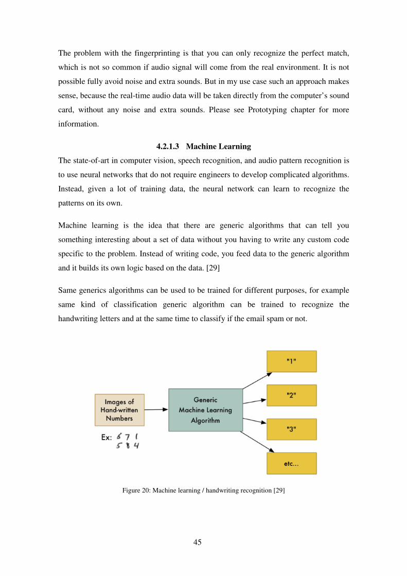
4.2.1.3 Machine Learning
The state-of-art in computer vision, speech recognition, and audio pattern recognition is
to use neural networks that do not require engineers to develop complicated algorithms.
Instead, given a lot of training data, the neural network can learn to recognize the
patterns on its own.
Machine learning is the idea that there are generic algorithms that can tell you
something interesting about a set of data without you having to write any custom code
specific to the problem. Instead of writing code, you feed data to the generic algorithm
and it builds its own logic based on the data. [29]
Same generics algorithms can be used to be trained for different purposes, for example
same kind of classification generic algorithm can be trained to recognize the
handwriting letters and at the same time to classify if the email spam or not.
Figure 20: Machine learning / handwriting recognition [29]

46
There are a huge variety of different machine learning algorithms and the main goal is
to choose the correct one to train for specific requirements.
Same approach can be used for sound classification.
Advantage of Machine learning approach that such a system can be trained to
recognize:
• Individual note
• Individual musical instrument
• Specific musical pattern
Especially the Specific musical pattern point is interesting for dancing fountain
approach. If artist find some specific musical pattern which he can hear from one song
to another, it might be difficult or even impossible to describe it by mathematical
function, but the machine learning algorithm can be trained to recognize these patterns.
The disadvantage of machine learning approach is the requirement of a huge amount of
example data to feed the algorithm for training.
Also, with machine leaning it’s important to remember that machine learning only
works if the problem is actually solvable with the data that you have. If you don’t’ have
certain amount of examples, you will not be able to train the algorithm and if a human
expert couldn’t use the data to solve the problem manually, a computer probably won’t
be able to either.
Please be informed that the Author of this Master’s thesis is not the qualified expert in
Machine/Deep learning and have the high level overview of this topic. In case of a real-
life implementation the consultation with the expert is required.
There are quite many works already done in the field of sound classification and some
of them can be re-used in my application [30], such as note or specific musical
instrument detection. But if Artist would like to implement some specific musical
pattern, then it will require a lot of input data. When it comes to deep learning, the data
is the key. Larger the data, better the accuracy.
47
Despite the fact that machine learning requires quite a lot of training (and validation)
data, this technology is the future and it can bring to life quite many solutions, which are
not possible to achieve with other technology.
Machine learning will represent the major part of audio patterns in dancing fountain
application.
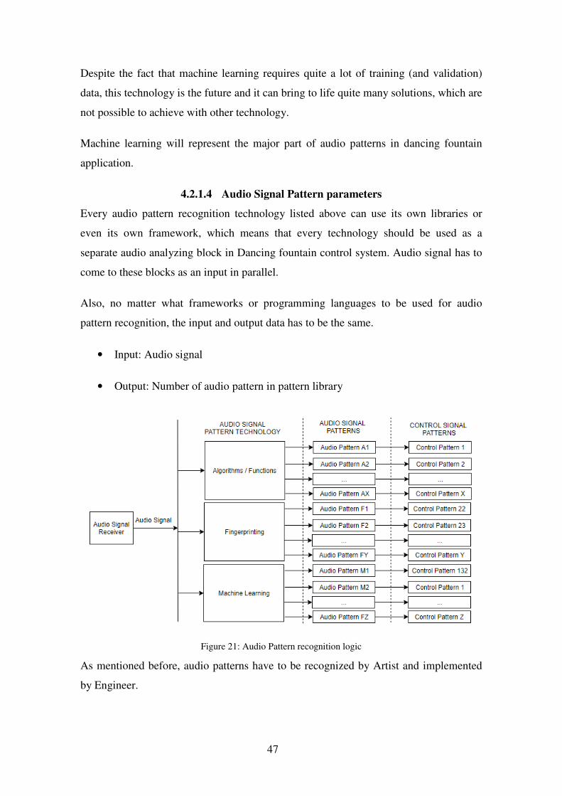
4.2.1.4 Audio Signal Pattern parameters
Every audio pattern recognition technology listed above can use its own libraries or
even its own framework, which means that every technology should be used as a
separate audio analyzing block in Dancing fountain control system. Audio signal has to
come to these blocks as an input in parallel.
Also, no matter what frameworks or programming languages to be used for audio
pattern recognition, the input and output data has to be the same.
• Input: Audio signal
• Output: Number of audio pattern in pattern library
As mentioned before, audio patterns have to be recognized by Artist and implemented
by Engineer.
Figure 21: Audio Pattern recognition logic

48
Each audio pattern added to the audio pattern library will have only one parameter (it
might be extended in future): Priority
“Priority parameter” is required to solve the conflicts if two or more patterns will be
recognized at the same time. For example:
• If violin and drums are playing at the same time and both of these patterns are
using the sprinkling Hydraulics unit,
• Or drums are playing repeatedly, but some defined by Artist pattern was
recognized and it has higher priority
The pattern with higher priority will be prioritized. Priority parameter will work within
one audio pattern recognition technology only, because the results from different sound
recognition blocks may come in different time. See more information in Validation
chapter.
4.2.2 Controls Signals patterns
At the same time it is necessary to create the control signal pattern per each recognized
musical pattern.
Control signal pattern is an array of signals required to control the hydraulics unit.
Hydraulics unit is an every device in the Dancing fountain that able to receive the
control signal. It can be:
• Motor Driver, which controls the water pump
• Electronic Valve
• Rotating Nozzles
Figure 22: Audio Pattern class

49
• 3D nozzle
It also can be the LEDs or light bulbs or projector, but they are out of the scope now.
Each control pattern can include as much hydraulics units of the system as necessary.
Even all of them. It has to be configured by the Artist. Every hydraulics unit is added
and configured one by one and attached into the Control pattern array.
Each patterns got its own reference number and all the parameters are saved into to
Control pattern library
List of the Hydraulics Units above looks fine from engineering point of view, but if, for
example, different nozzles will be attached to the same pipe, controlled by the same
water pump, from Artist point of view it will be already different unit. Visually the
water jet will also look differently and will have different parameters.
So, from technical point of view, engineer can define the technical hydraulics units and
Artist can split the technical units to sub-units. Specific parameters can be defined for
Control pattern and per each Hydraulics unit.
Figure 23: Create new control pattern Activity Diagram
Figure 24: Control pattern class diagram

50
Table 2: Hydraulics Unit parameters
Unit Parameter Hydraulics Unit Control method Controlling device Comments
Height Motor driver with Water pump
PWM Signal Pump Motor Driver Height of water jet in millimetres
Rotation speed Rotation Nozzle PWM Signal Rotating nozzle motor drive
Rotation speed in rpm
Intervals Electronic Valves
Control signal to Relay
Power relay Int array for open and closed intervals in milliseconds
Slow Motion Motor driver with Water pump
PWM Signal Pump Motor Driver Water jet fast Up but Slow down. Delay in Milliseconds.
Table 3: Control Pattern parameters
Pattern Parameter Comments
Duration Time to accomplish this pattern in Milliseconds
Immediate action Wait until the execution of previous control pattern ends of act immediately
Waiting time How long it is fine to wait to execute the current Control Pattern
Can interrupt
If value is FALSE, this pattern execution can’t be interrupted, even if the other pattern has Immediate action Value = TRUE
4.2.3 Audio And Control patterns matching
When variety of Audio and Control patterns are added to the library Artist can make an
Audio Pattern <> Control Pattern combination.

51
Every control pattern may have many audio patterns, but every Audio pattern may have
only one control patterns. Other words, the behavior of the fountain may be the same for
different Audio patterns.
4.3 Dancing Fountain Control system
I expect to get only the audio pattern ID from the audio pattern recognizer system block.
Every Audio pattern should be connected to Control pattern so, the next step would be
to request the relevant Control pattern with parameters from Control Pattern library.
4.3.1 Validation block
Despite that we have the priority control in every audio pattern recognition block; there
might be two scenarios when we can receive another Audio pattern ID at a time when
the execution of previous one is not finished yet.
1. New Audio pattern ID will come from another Audio recognition block.
2. New Audio pattern ID will come from the same block, but control pattern
execution time is different and if, for example, some pattern execution will last
for 5 seconds, most probably many more audio patterns will be recognized
during this time.
That’s why every Control pattern needs the parameters described in “Control signal
patterns” chapter.
Figure 25: Audio to Control pattern combination
Figure 26: Dancing Fountain Control part

52
In Validation block will be two controls:
1. Availability control: It will check that pumps, valves and nozzles, required for
this control pattern execution are not busy at the moment.
2. Timing Control: If Availability control is failed, timing control will check is this
Control pattern should be added to the queue or just dismissed from the
execution.
Timing control:
1. Immediate action: shows should all the currently executable patterns stop and
execution of this pattern start or not.
2. Can interrupt the currently executed pattern also depend of the currently
executable pattern parameter “Can Interrupt”. If it is true, then this control
pattern execution can be interrupted.
3. Each Control pattern has “Waiting time” parameter. If waiting time is less than
the total time in the queue, this control pattern can be added to the queue then.
Otherwise it will be just dismissed.
Figure 27: Validation Block

53
4.3.2 Control Signals technology
Control signals to Hydraulic Units will come to the Executable block and will for the
queue.
It is necessary to consider that every control pattern may include more than one
Hydraulic unit. It can include even all of them, which means that the controller has to be
able to send control signals to all the Hydraulic Units at the same time.
The DMX technology [10] already briefly explained in this Master’s thesis can be used
to control each element (or group of elements) in the dancing fountain system.
Controllers generate serial signals in DMX512 format. It is a master-slave system where
the first controller acts as the master, and the second controller acts as a slave to the first
controller but as a master controller to the next controllers that are attached.
This technology is mainly used in lightning, but can be also adjusted to control other
dancing fountain units. Basically, it is possible to implement any other Bus technology,
but as DMX already has quite many use cases to be used in Fountain industry – it makes
sense to take it in my use case as well.
4.4 Outcome
As a final result now I have the structure of experimental Self-Choreographed Dancing
Fountain with description of:
• System concept
• System blocks
• System processes
• System parameters
Based on this information it is possible to start building the real life system.
4.4.1 Dancing Fountain Control system concept
Top level overview of the Dancing fountain control system.

54
Figure 28: Self-Choreographed dancing fountain control system
Figure 29: Self-Choreographed dancing fountain control system class diagram

55
5 Prototyping
Self-choreographed dancing fountain control system prototyping will be based on the
structure described in the previous chapter.
Control system interface will be developed in Microsoft Visual Studio, using C#
language. This interface will play the role of the container for all the modules
represented on the scheme above. Some modules will be developed by Engineer, but
some modules will use already existing solutions on the market.
• Green: These modules to be developed in-house, specifically for this application.
• Blue: Modules, which will use the external libraries or other frameworks. This
libraries or frameworks will work as separate units, but will have the
interface/protocol (input/output parameters) to be integrated into the common
container.
• Red: External expert assistance is required.
It is necessary to understand, that the Self-choreographed dancing fountain control
system presented in prototyping chapter is only the early stage of the product
Figure 30: Self-Choreographed dancing fountain control system development

56
development. It gives the understanding of the overall concept, but still lacking a lot of
functionality. It has to be extended with required functionality step by step.
5.1 Audio receiver
There are two options, how to read the audio signal:
1. Using the microphone
2. Directly from the device
In first case we will get a lot of extra signals, such as noise, which will make audio
pattern recognition more difficult and in case of Fingerprinting even not possible. So,
the second option is more preferable. WASAPI can be used for these purposes.
The Windows Audio Session API (WASAPI) enables client applications to manage the
flow of audio data between the application and an audio endpoint device. [23]
Basically, it provides a mixer API that talk directly to your sound card. No need of
microphone to read the audio signal. It handles sample rate conversion, recording, audio
effects and everything that's Audio related. This API is supported starting from
Windows 7.
5.1.1 Bass.dll library
When looking for alternative to Matlab tools for audio simulation I came across with
“bass.dll” audio library developed by “Un4seen Developments” company [21].
BASS is an audio library for use in software on several platforms. Its purpose is to
provide developers with powerful and efficient sample, stream (MP3, MP2, MP1, OGG,
WAV, AIFF, custom generated, and more via OS codecs and add-ons), MOD music
(XM, IT, S3M, MOD, MTM, UMX), MO3 music (MP3/OGG compressed MODs), and
recording functions. All in a compact DLL that won't bloat your distribution. [21]
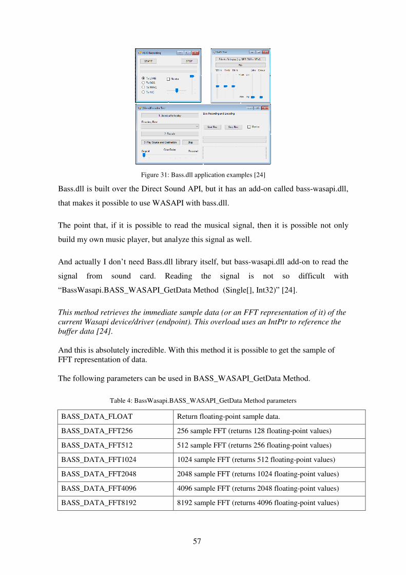
Other words, this library gives the powerful set of tools to create own music player or sound recorder or online radio client etc.
57
Bass.dll is built over the Direct Sound API, but it has an add-on called bass-wasapi.dll,
that makes it possible to use WASAPI with bass.dll.
The point that, if it is possible to read the musical signal, then it is possible not only
build my own music player, but analyze this signal as well.
And actually I don’t need Bass.dll library itself, but bass-wasapi.dll add-on to read the
signal from sound card. Reading the signal is not so difficult with
“BassWasapi.BASS_WASAPI_GetData Method (Single[], Int32)” [24].
This method retrieves the immediate sample data (or an FFT representation of it) of the
current Wasapi device/driver (endpoint). This overload uses an IntPtr to reference the
buffer data [24].
And this is absolutely incredible. With this method it is possible to get the sample of FFT representation of data. The following parameters can be used in BASS_WASAPI_GetData Method.
Table 4: BassWasapi.BASS_WASAPI_GetData Method parameters
BASS_DATA_FLOAT Return floating-point sample data.
BASS_DATA_FFT256 256 sample FFT (returns 128 floating-point values)
BASS_DATA_FFT512 512 sample FFT (returns 256 floating-point values)
BASS_DATA_FFT1024 1024 sample FFT (returns 512 floating-point values)
BASS_DATA_FFT2048 2048 sample FFT (returns 1024 floating-point values)
BASS_DATA_FFT4096 4096 sample FFT (returns 2048 floating-point values)
BASS_DATA_FFT8192 8192 sample FFT (returns 4096 floating-point values)
Figure 31: Bass.dll application examples [24]

58
BASS_DATA_FFT_INDIVIDUAL Use this flag to request separate FFT data for each channel. The size of the data returned (as listed above) is multiplied by the number channels.
BASS_DATA_FFT_NOWINDOW This flag can be used to prevent a hanning window being applied to the sample data when performing an FFT.
BASS_DATA_AVAILABLE Query the amount of data the device has buffered (the BASS_WASAPI_BUFFER flag isn't required for this, buffer can be null when using this flag).
So, for example, if I want to get the sampling rate of 44100Hz for my audio analyzing; I
can take GetData with “BASS_DATA_FFT8192” parameter a little more than 5 times per
second (5.4 times). With bass.dll and WASAPI I can get the powerful tool to receive the
audio.
bass-wasapi.dll library will be integrated into the Dancing control system container and
will be used as audio receiver for in all audio recognition technologies.
5.2 Audio Pattern recognition
This is the major part in signal processing and the overall dancing control system as
well. As it was described below, there are three different technologies to be used in
musical pattern recognition and each technology requires the specific approach.
5.2.1 Algorithms / Functions technology
This technology will be used by Engineer to develop the Audio pattern algorithms. If
the Audio pattern, recognized by Artist could be described with specific mathematical
functions – it will be first option to go then. If not – alternative technology will be
analyzed.
Most common approach is to use FFT representation of the signal and compare every
following sample with the previous one or with the series of previous samples.
All algorithmic patterns will be store in a separate library.
5.2.1.1 Example: Loudness difference audio pattern
“Loudness difference” patterns should analyze the signal and if there will be big
difference in Loudness is a short period of time, then shoot from all the nozzles as
powerful as possible.

59
BassWasapi.dll library has “BassWasapi.BASS_WASAPI_GetLevel” Method. I
can use this method to take the loudness levels per each sample and compare it with the
previous one. In this example it is not even matter the scale of maximum and minimum
values. What matters is the difference between these two levels.
Figure 32: Loudness difference pattern logic
Maximum value from every sample has to be compared to the value from the previous
sample. If the difference is more than 10 times (this value has to be tested, might be
higher) then raise the flag with the pattern ID.
All the logic is running inside the Timer. Controlling the timer interval it is possible to
control the number of samples per second.
The overall approach is to re-use already existing in the market high quality products,
such as bass.dll library and create the tailor made functions for the specific needs.
5.2.2 Fingerprinting technology
Fingerprinting technology is an important part of audio pattern recognition module. It is
required when artist wants to run the certain control pattern at a certain moment of a
known audio track. It can be a song, or a vocal moment or anything else, the only
requirement – it should be the exact match with the sample from the library.
It means that the fingerprinting technology requires at least two functionalities:
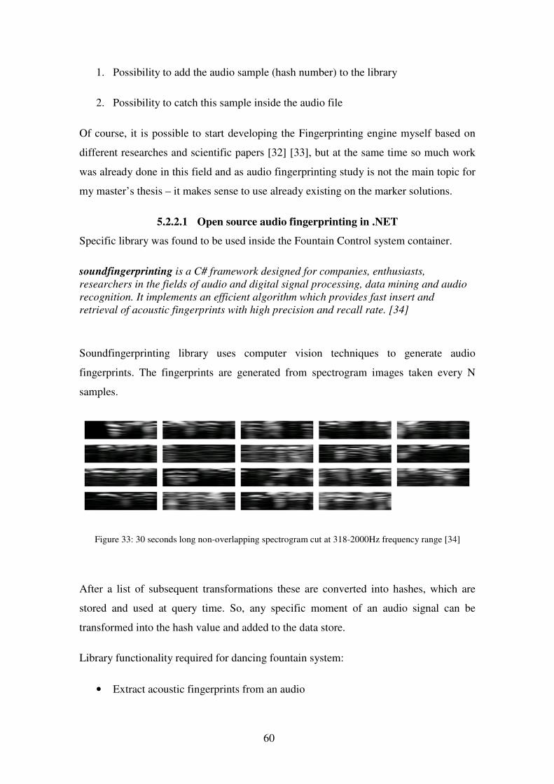
60
1. Possibility to add the audio sample (hash number) to the library
2. Possibility to catch this sample inside the audio file
Of course, it is possible to start developing the Fingerprinting engine myself based on
different researches and scientific papers [32] [33], but at the same time so much work
was already done in this field and as audio fingerprinting study is not the main topic for
my master’s thesis – it makes sense to use already existing on the marker solutions.
5.2.2.1 Open source audio fingerprinting in .NET
Specific library was found to be used inside the Fountain Control system container.
soundfingerprinting is a C# framework designed for companies, enthusiasts,
researchers in the fields of audio and digital signal processing, data mining and audio
recognition. It implements an efficient algorithm which provides fast insert and
retrieval of acoustic fingerprints with high precision and recall rate. [34]
Soundfingerprinting library uses computer vision techniques to generate audio
fingerprints. The fingerprints are generated from spectrogram images taken every N
samples.
Figure 33: 30 seconds long non-overlapping spectrogram cut at 318-2000Hz frequency range [34]
After a list of subsequent transformations these are converted into hashes, which are
stored and used at query time. So, any specific moment of an audio signal can be
transformed into the hash value and added to the data store.
Library functionality required for dancing fountain system:
• Extract acoustic fingerprints from an audio

61
• Store the fingerprints in the datastore
• Query the storage in order to recognize the song those samples you have
Overall concept is to take the audio sample with certain length and query the
fingerprints storage. The origin of query samples may vary: file, URL, microphone,
radio tuner, etc.
The really important part of this library, that in version 6.2.0 it provides ability to query
real-time datasources. It gives the opportunity to monitor a real-time stream and get
matching results as fast as possible.
Query reply also contains the extensive information, such as number or matched track
from the datastore, position where resulting track started, confidence (returns a value
between [0, 1]. A value below 0.15 is most probably a false positive) and many more.
In my use case the matched track number is the most important parameter and it will
correspond to audio pattern ID and in case of positive result will be forwarded to control
part.
Audio fingerprinting technology and Soundfingerprinting library will be the second
choice (after mathematical functions) to implement defined by artist audio patterns.
5.2.3 Machine learning technology
If algorithmic functions and audio fingerprinting technology is not able to implement
the required audio patters – machine learning comes into play then.
Machine learning technology is cutting edge technology these days. As already
mentioned before, the author of this Master’s thesis has an overall idea of the
Machine/Deep learning technology, but he is definitely not the expert in this field.
Outsourced Machine learning expert is required to implement this module into the
Dancing fountain control system container. This task has to be accomplished once.
When generic algorithm is developed it will be up to Artist to train this algorithm by
feeding it with training, validation and test patterns.
62
5.3 Control pattern configuration
Control pattern configurator will be fully created by Engineer and will contain three
major parts:
1. Audio Pattern library: Catalog of all the patterns IDs with their priorities. Please
don’t confuse with the “real” audio patterns. They are different from one audio
pattern recognition technology to another and will be stored in the relevant
blocks (Functions, Fingerprints etc.).
2. Control Pattern Library: Catalog of Control patterns.
3. Library of Audio to Control Pattern combinations.
Each Pattern combination will have a separate .config file. Each control Pattern will
have the Collection of Hydraulic Units. Each Hydraulic Unit will have its own set of
parameters.
Visual studio “Property Grid” is a flexible tool to store all the required parameters.
Hierarchical approach can be used with the Collections.

63
5.4 Validations & Hydraulics Control
5.4.1 Validations
As described before Availability and Timing control will be represented as a separate
functions inside the main system container. These functions will be developed by
engineer.
5.4.2 Hydraulic Control
Hydraulics control part will be the combination of tailor made DMX512 master
microcontroller. It doesn’t mean that specific microcontroller board will be created, but
Figure 34: Pattern Configurator window
64
available on the marker board will be extended with DMX512 support considering the
DMX specifics, such as packet structure [31].
This also means that each pattern configured in Control Pattern Configurator has to be
replicated inside the DMX Controller library. When the controller will receive the
control pattern ID it has to immediately send all the control signals
DMX controller is an end point. If it receives the pattern ID - it starts immediate
execution. All validation and queuing logic implemented in validation block.
As DMX512 is a master-slave technology, each Hydraulic unit requires the DMX
controller as well.
5.5 Hydraulic Units
All the Hydraulics parts are commercial products. No in-house development is planned.
Each Hydraulic unit is specific and has to be analyzed separately. Important features
are:
• Built-in DMX controller
• System integration possibility
Here are couple examples:
Pumps: There are quite many water pumps on the market with built-in DMX controller
and as the protocol is the same, it can be attached to already existing system and this
Hydraulic Unit can be added to the library.
3D Nozzles: Each 3D nozzle is a complex system and every vendor provides its own
Nozzle behavior configuration software. The important feature of this software is the
possibility of integration with the Dancing Control system described in this Master’s
thesis. Configuration software requires specific API or other interaction possibilities.
5.6 Simulator & tester
While prototyping, I’ve found the interesting possibility to use progress bars [22] to
imitate the fountain water jet behavior

65
First, I’ve implemented the Light organ approach to this simulator. It is reading the FFT
data received from the sound card, checks the ranges (Low Channel 60-150 Hz, Mid
channel 200-600 Hz, and High channel 800-2200 Hz) and take maximum from these
ranges.
Secondly, I’ve implemented the “Loudness change” audio pattern.
Figure 35: Dancing Fountain Simulator
Please see more detailed simulator development steps in Appendix 3.
I’ve also decided to attach my Hydraulics tester with one pump described in this
master’s thesis before. Arduino Uno will send the PWM control signal to motor driver,
which means that I have to send the PWM values to Arduino first.
Please see Appendix 4 for more information about Simulator to Arduino connection.
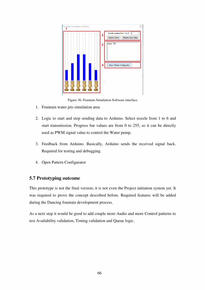
66
1. Fountain water jets simulation area
2. Logic to start and stop sending data to Arduino. Select nozzle from 1 to 6 and
start transmission. Progress bar values are from 0 to 255, so it can be directly
used as PWM signal value to control the Water pump.
3. Feedback from Arduino. Basically, Arduino sends the received signal back.
Required for testing and debugging.
4. Open Pattern Configurator
5.7 Prototyping outcome
This prototype is not the final version; it is not even the Project initiation system yet. It
was required to prove the concept described before. Required features will be added
during the Dancing fountain development process.
As a next step it would be good to add couple more Audio and more Control patterns to
test Availability validation, Timing validation and Queue logic.
Figure 36: Fountain Simulation Software interface

67
6 Summary
Master’s thesis main objective was to plan and prototype the self-choreographed
dancing fountain system, which is reacting on real-time audio signal and automatically
synchronizes water movements with music to achieve the artistic effect.
After several iterations and major change of concept in the middle of research it is
possible to say that this study has measurable outcomes:
• It was proved that the color organ approach in self-choreographed dancing
fountain system could be implemented and is fully operational from technical
point of view, but has no much artistic value.
• Considering all the artist requirements, the top level architecture of the self-
choreographed dancing fountain system was planned. The major functionality of
the system is audio pattern recognition (with use of different in-house or external
technology) and hydraulics control pattern library to synchronize the incoming
audio signal with water movements.
• Prototyping of the product with minimum viable functionality was initiated and
several example modules were developed. At the same time, the possibility of
using external libraries for specific system modules was analyzed and specific
technology presented.
• One of the important outcomes of this study is the understanding that it is not
possible yet to fully rely on machines in some areas. Even if the fountain will
work autonomously without human interaction, all the pre-configuration of the
fountain behavior has to be done by human.
It is necessary to understand that this study contains the overall proves of concept, but
not the final product. Further development is required. The next step would be:
• Develop the fully functional engine of dancing fountain system including the
following parts: Pattern configurator, Validations block, and Control block.

68
• Embed the audio fingerprinting external library into the system container.
• Involve an external expert to develop the machine learning part of audio pattern
recognition module.
• Enrich the audio pattern library with defined by artist patterns per each audio
pattern recognition technology.
• Find or develop the real life hydraulic part of the dancing fountain and add
control patterns defined by artist to the library.
Next steps presented above are the high level overview of required actions to develop
the fully operational system. To start the development process, project initiation
document has to be created with overall project description; more detailed technical
requirements per each module and roles for all the involved parties. When this is done it
is possible to plan the budgets (time, money) and discuss the development
approach/methodology.
As the main goal for this master’s thesis was to plan, prototype and document the
overall concept of the self-choreographed dancing fountain system with description of
top level architecture, major processes and parameters, I can assume than this job is
done.

69
References
[1] Cambridge Dictionalry: https://dictionary.cambridge.org/dictionary/english/fountain
[2] Belagio https://en.wikipedia.org/wiki/Bellagio_(resort)#Fountains_of_Bellagio
[3] The History Of The Magic Fountain Of Montjuïc In 1 Minute https://theculturetrip.com/europe/spain/articles/the-history-of-the-magic-fountain-of-montjuic-in-1-minute/
[4] Self-Choreographed Musical Fountain System, Andrea Natasha Gonsalves, Claran Joel Martis, Nandini Maninarayana, SSRG International Journal of Electronics and Communication Engineering ( SSRG – IJECE ) – Volume 3 Issue 10 – October 2016 https://pdfs.semanticscholar.org/0372/09dae0e103bbad5358065f7bafa67efae91c.pdf
[5] How to make a dancing fountain http://www.saferain.com/en/blog/how-to-make-a-dancing-fountain.html
[6] SMART ELECTRONIC SYSTEM FOR DANCING FOUNTAINS CONTROL CAPABLE TO CREATE WATER AND LIGHTING SCENARIOS SYNCHRONIZED WITH A MUSIC TRACK, Paolo Visconti, Paolo Costantini, Cavalera, Department of Innovation Engineering, University of Salento, Monteroniroad, Lecce, Italy http://www.arpnjournals.org/jeas/research_papers/rp_2016/jeas_0516_4166.pdf
[7] Paai Show Control http://fountain.paai.xyz/ShowControl.html
[8] H2Oarts Water Feature Automtion, Content, Technology, Design http://www.h2oarts.com/
[9] Arduino DC Motor Control Tutorial – L298N | PWM | H-Bridge https://howtomechatronics.com/tutorials/arduino/arduino-dc-motor-control-tutorial-l298n-pwm-h-bridge/
[10] DMX Explained; DMX512 and RS-485 Protocol Detail for Lighting Applications https://www.element14.com/community/groups/open-source-hardware/blog/2017/08/24/dmx-explained-dmx512-and-rs-485-protocol-detail-for-lighting-applications
[11] Arduino – Home: https://www.arduino.cc/
[12] Arduino Refence, AnalogWrite() https://www.arduino.cc/reference/en/language/functions/analog-io/analogwrite/

70
[13] Figure: Light organ: http://www.technology.niagarac.on.ca/people/mcsele/wp-content/uploads/2017/11/Colorgan-Complete.gif
[14] Colorgan IV | Professor Mark Csele http://www.technology.niagarac.on.ca/people/mcsele/hobby/colorgan-iv/
[15] Sound Signal Analysis Using FIR Filters for Musical Fountain Operation
Ali M. Jasim Jawad R. Mahmood Ramzy S. Ali, Basrah Journal for Engineering Sciences, vol. 16, no. 2, 2016
[16] Introduction to Filters: FIR versus IIR - Siemens PLM Community view-source:https://community.plm.automation.siemens.com/t5/Testing-Knowledge-Base/Introduction-to-Filters-FIR-versus-IIR/ta-p/520959
[17] Arduino Microfone Sound Sensor Module: https://tkkrlab.nl/wiki/Arduino_KY-038_Microphone_sound_sensor_module
[18] Object for recording Audio – MATLAB: https://www.mathworks.com/help/matlab/ref/audiorecorder.html
[19] Music Visualization with Fourier Transform: https://pragmacoders.com/blog/music-visualization-with-the-fourier-transform
[20] An Introduction to Processing and Music Visualization, Christopher Pramerdorfer, Vienna University of Technology, 2011.01.16
[21] Un4seen Developments - 2MIDI / BASS / MID2XM / MO3 / XM-EXE / XMPlay: http://www.un4seen.com/
[22] Making an Audio Spectrum analyzer with Bass.dll, C# and Arduino – CodeProject: https://www.codeproject.com/Articles/797537/Making-an-Audio-Spectrum-analyzer-with-Bass-dll-Cs
[23] About WASAPI – Windows Applications | Microsoft Docs: https://docs.microsoft.com/en-us/windows/desktop/coreaudio/wasapi
[24] BASS.NET API for the Un4seen BASS Audio Library: http://bass.radio42.com/help/
[25] Arduino StringToInt Example: https://www.arduino.cc/en/Tutorial.StringToIntExample
[26] Duplicate songs detector via audio fingerprinting – CodeProject: https://www.codeproject.com/Articles/206507/Duplicates-detector-via-audio-fingerprinting

71
[27] Open source audio fingerprinting in .NET. An efficient algorithm for acoustic fingerprinting written purely in C#.: https://github.com/AddictedCS/soundfingerprinting
[28] The Goertzel Algorithm: https://www.embedded.com/design/configurable-systems/4024443/The-Goertzel-Algorithm
[29] Machine Learning is Fun! – Adam Geitgey – Medium: https://medium.com/@ageitgey/machine-learning-is-fun-80ea3ec3c471
[30] Using Deep Learning For Sound Classification: An In-Depth Analysis: https://www.analyticsindiamag.com/using-deep-learning-for-sound-classification-an-in-depth-analysis/
[31] Introduction to DMX: https://learn.sparkfun.com/tutorials/introduction-to-dmx/all
[32] A Highly Robust Audio Fingerprinting System, Jaap Haitsma (Philips Research), Ton Kalker (Philips Research)
[33] Social- and Interactive-Television, Applications Based on Real-Time Ambient-Audio Identification
Michael Fink (Center for Neural Computation, Hebrew University of Jerusalem),Michele Covell and Shumeet Baluja (Google Research, Google Inc.)
[34] AddictedCS/soundfingerprinting: Open source audio fingerprinting in .NET. An efficient algorithm for acoustic fingerprinting written purely in C# : https://github.com/AddictedCS/soundfingerprinting

72
Appendix 1 – [Arduino codes]
// WATER DELAY TEST
#include <boarddefs.h>
#include <IRremote.h>
#include <IRremoteInt.h>
#include <ir_Lego_PF_BitStreamEncoder.h>
#define OUT1 12
#define EnB 5
#define In4 6
#define In3 7
int speed;
int RECV_PIN = 11;
IRrecv irrecv(RECV_PIN);
decode_results results;
void setup()
{
Serial.begin(9600);
irrecv.enableIRIn(); // Start the receiver
pinMode(OUT1, OUTPUT);
pinMode(EnB, OUTPUT);
pinMode(In3, OUTPUT);
pinMode(In4, OUTPUT);
// turn off motor B
digitalWrite(In3, LOW);
digitalWrite(In4, LOW);
}
void loop()
{
if (irrecv.decode(&results))
{
//LED ON & OFF
if (results.value == 16582903) digitalWrite(OUT1, HIGH);
if (results.value == 16615543) digitalWrite(OUT1, LOW);

73
//Speed control
if (results.value == 16599223) speed = 100; // Button 3
if (results.value == 16591063) speed = 150; // Button 4
if (results.value == 16623703) speed = 200; // Button 5
// Turn OFF motor
if (results.value == 16580863) { // Button Power
digitalWrite(In3, LOW);
digitalWrite(In4, LOW);
}
// Turn ON motor
if (results.value == 16593103) { // Button 0
digitalWrite(In3, LOW);
digitalWrite(In4, HIGH);
speed = 100;
}
Serial.println(results.value);
irrecv.resume(); // Receive the next value
}
analogWrite(EnB, speed);
}
// SOUND VOLUME TO PWM SIGNAL
int sensorPin = A0; // select the input pin for the potentiometer
int sensorValue = 0; // variable to store the value coming from the
sensor
#define EnB 5
#define In4 6
#define In3 7
int speed;
void setup ()
{
Serial.begin (9600);
pinMode(EnB, OUTPUT);
pinMode(In3, OUTPUT);
pinMode(In4, OUTPUT);
// turn ON motor
digitalWrite(In3, LOW);
digitalWrite(In4, HIGH);
speed = 100;
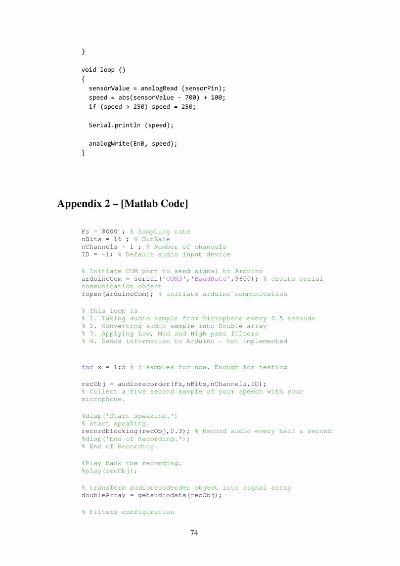
74
}
void loop ()
{
sensorValue = analogRead (sensorPin);
speed = abs(sensorValue - 700) + 100;
if (speed > 250) speed = 250;
Serial.println (speed);
analogWrite(EnB, speed);
}
Appendix 2 – [Matlab Code]
Fs = 8000 ; % Sampling rate nBits = 16 ; % BitRate nChannels = 1 ; % Number of chaneels ID = -1; % Default audio input device
% Initiate COM port to send signal to Arduino arduinoCom = serial('COM3','BaudRate',9600); % create serial
communication object fopen(arduinoCom); % initiate arduino communication
% This loop is % 1. Taking audio sample from Microphone every 0.5 seconds % 2. Converting audio sample into Double array % 3. Applying Low, Mid and High pass filters % 4. Sends information to Arduino - not implemented
for x = 1:5 % 5 samples for now. Enough for testing
recObj = audiorecorder(Fs,nBits,nChannels,ID); % Collect a five second sample of your speech with your
microphone.
%disp('Start speaking.') % Start speaking. recordblocking(recObj,0.3); % Record audio every half a second %disp('End of Recording.'); % End of Recording.
%Play back the recording. %play(recObj);
% transform audiorecoderder object into signal array doubleArray = getaudiodata(recObj);
% Filters configuration

75
filtlp = designfilt('lowpassiir', 'PassbandFrequency', .13,
'StopbandFrequency', .15, 'PassbandRipple', 1,
'StopbandAttenuation', 60); filtbp = designfilt('bandpassiir', 'StopbandFrequency1', .2,
'PassbandFrequency1', .22, 'PassbandFrequency2', .58,
'StopbandFrequency2', .6, 'StopbandAttenuation1', 60,
'PassbandRipple', 1, 'StopbandAttenuation2', 60); filthp = designfilt('highpassiir', 'StopbandFrequency', .78,
'PassbandFrequency', .8, 'StopbandAttenuation', 60,
'PassbandRipple', 1);
% Run the filters filteredlp = filter(filtlp,doubleArray); filteredbp = filter(filtbp,doubleArray); filteredhp = filter(filthp,doubleArray);
% Plot the Original and 3 filtered signals.
% figure; % subplot(4,1,1); % plot(doubleArray); % title('Original'); % subplot(4,1,2); % plot(filteredlp); % title('Low-Pass') % % subplot(4,1,3); % plot(filteredbp); % title('Band-Pass') % % subplot(4,1,4); % plot(filteredhp); % title('High-Pass')
% Take maximum values of Filter arrays OR = maxk(doubleArray,1); % Original signal LP = maxk(filteredlp,1); % Low-Pass signal BP = maxk(filteredbp,1); % Band-pass signal HP = maxk(filteredhp,1); % High-pass signal
% Display maximum values in console disp(['Real',num2str(OR),';','Low-Pass',num2str(LP),';','Band-
Pass',num2str(BP),';','High-Pass',num2str(HP),';']);
ALP = round(LP*1000); % signal value is multiplied by 1000 and
all the outstanding decimals are removed to get the integer
value disp(ALP);
fprintf(arduinoCom, '%i', AOR); % send answer variable content
to arduino
end
fclose(arduinoCom); % Close COM port

76
Appendix 3 – [Fountain Simulator]
I will use Microsoft Visual Studio 2017 and C# programming language to build the
Fountain simulator software.
Spectrum Daemon example [22] shows the possibility of using FFT data received from
the sound card with progress bars and Wave graphs.
Wave graph is not something what we need, but progress bars are looks quite similar to
the water jets and can be used as to emulate the water jet behavior.
Current example has 64 progress bars in a row (not all of them are visible). I’ve decided
to decrease the amount to six. This number is not so important at this moment because it
can be easily scalable. I’ve just decided to take the amount of Arduino Analog pins.
The goal for my first version of simulator would be the simulation of Light organ
approach from my first iteration.
Current example is using the following code to split 4096 values into 64 progress bars:
Figure 37: Audio Spectrum Analyser example
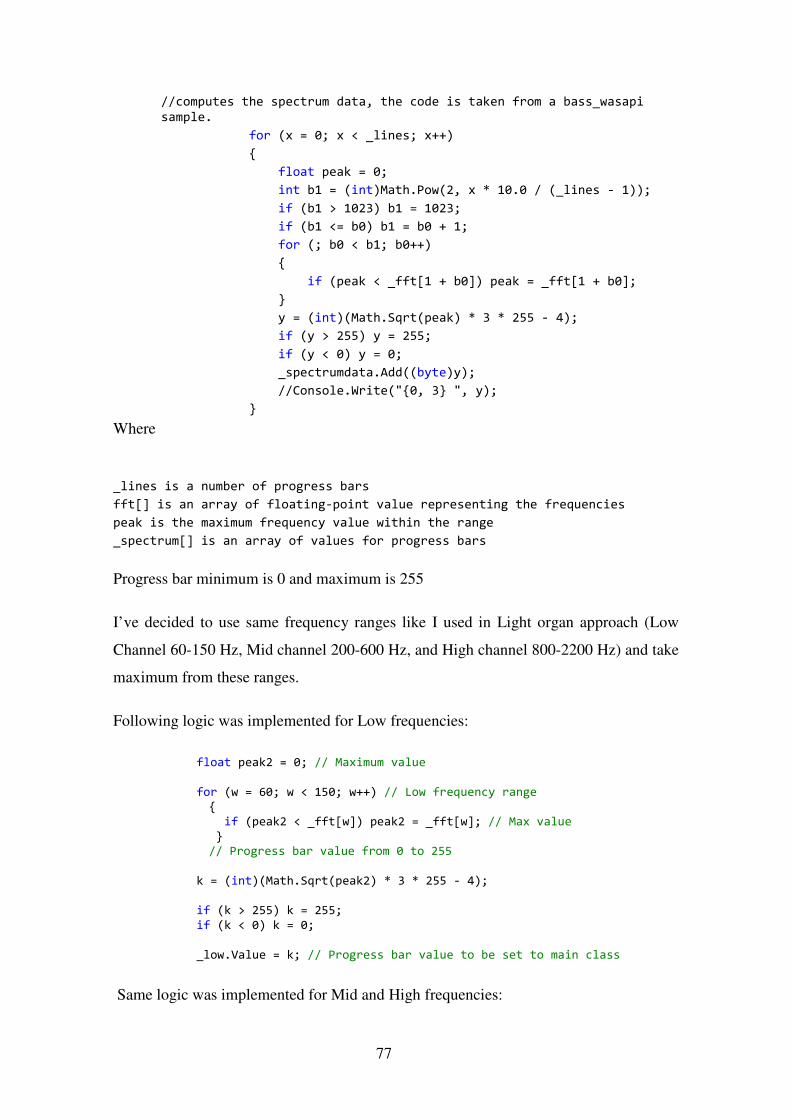
77
//computes the spectrum data, the code is taken from a bass_wasapi
sample.
for (x = 0; x < _lines; x++)
{
float peak = 0;
int b1 = (int)Math.Pow(2, x * 10.0 / (_lines - 1));
if (b1 > 1023) b1 = 1023;
if (b1 <= b0) b1 = b0 + 1;
for (; b0 < b1; b0++)
{
if (peak < _fft[1 + b0]) peak = _fft[1 + b0];
}
y = (int)(Math.Sqrt(peak) * 3 * 255 - 4);
if (y > 255) y = 255;
if (y < 0) y = 0;
_spectrumdata.Add((byte)y);
//Console.Write("{0, 3} ", y);
}
Where
_lines is a number of progress bars
fft[] is an array of floating-point value representing the frequencies
peak is the maximum frequency value within the range
_spectrum[] is an array of values for progress bars
Progress bar minimum is 0 and maximum is 255
I’ve decided to use same frequency ranges like I used in Light organ approach (Low
Channel 60-150 Hz, Mid channel 200-600 Hz, and High channel 800-2200 Hz) and take
maximum from these ranges.
Following logic was implemented for Low frequencies:
float peak2 = 0; // Maximum value
for (w = 60; w < 150; w++) // Low frequency range {
if (peak2 < _fft[w]) peak2 = _fft[w]; // Max value
} // Progress bar value from 0 to 255
k = (int)(Math.Sqrt(peak2) * 3 * 255 - 4);
if (k > 255) k = 255;
if (k < 0) k = 0;
_low.Value = k; // Progress bar value to be set to main class
Same logic was implemented for Mid and High frequencies:

78
peak2 = 0;
for (w = 200; w < 600; w++) {
if (peak2 < _fft[w]) peak2 = _fft[w];
} k = (int)(Math.Sqrt(peak2) * 3 * 255 - 4);
if (k > 255) k = 255;
if (k < 0) k = 0; _mid.Value = k;
peak2 = 0;
for (w = 800; w < 2200; w++)
{
if (peak2 < _fft[w]) peak2 = _fft[w]; }
k = (int)(Math.Sqrt(peak2) * 3 * 255 - 4);
if (k > 255) k = 255; if (k < 0) k = 0;
_high.Value = k;
As I have 6 progress bars in my simulator I’ve decided to implement them the way:
LOW (Bar 3, 4), Mid (Bar 2, 5), High (Bar 1, 6).
The good thing is that I can easily modify all of that, if necessary.
All the programming code is running inside the timer, so it easy to modify how many
times per second run the code. I’ve configured it to be taken 5 times per second.
Appendix 4 – [Simulator to Arduino Connection]
SerialPort object was added to my project:
Figure 38: SerialPort object configuration

79
Now it is possible to use COM3 serial port (which is my Arduino Uno connection port)
with the following commands:
serialPort1.Open();
serialPort1.Close();
serialPort1.WriteLine();
I’ve added one more timer to be able to control the frequency of sending the
information to Arduino and added some elements to the interface.
1. Fountain water jets simulation area
2. Logic to start and stop sending data to Arduino. Select nozzle from 1 to 6 and
start transmission. Progress bar values are from 0 to 255, so it can be directly
used as PWM signal value to control the Water pump.
3. Feedback from Arduino. Basically, Arduino sends the received signal back.
Required for testing and debugging.
Following Timer’s logic was implemented in Visual Studio to send over COM port:
// Checks if Start Arduino trasfer button is clicked. When the button is clicked COM3 port is opened then and this variable is set to true.
if (_arduinoSend == true)
{
int _iNozzle;
// Read the Nozzle number from the texbox
_iNozzle = Convert.ToInt32(txtNozzle.Text);
Figure 39: Fountain Simulation Software interface

80
if (_iNozzle == 1) serialPort1.WriteLine(Convert.ToString(progressBar5.Value));
if (_iNozzle == 2)
serialPort1.WriteLine(Convert.ToString(progressBar4.Value)); if (_iNozzle == 3)
serialPort1.WriteLine(Convert.ToString(progressBar3.Value));
if (_iNozzle == 4) serialPort1.WriteLine(Convert.ToString(progressBar3.Value));
if (_iNozzle == 5)
serialPort1.WriteLine(Convert.ToString(progressBar4.Value)); if (_iNozzle == 6)
serialPort1.WriteLine(Convert.ToString(progressBar5.Value));
// Write sended value to consile for debugging
//Console.WriteLine(Convert.ToString(progressBar5.Value));
}
Not the most elegant code, but it works for testing purposes.
Following line was added to read the repeated signal from Arduino and write it to Rich
TextBox.
richTextBox1.Text = serialPort1.ReadExisting() + "\n";
On the Arduino side [25] it was necessary to read the COM port information.
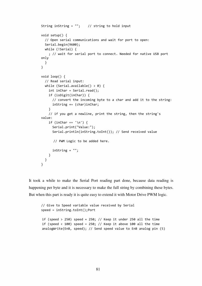
81
String inString = ""; // string to hold input
void setup() {
// Open serial communications and wait for port to open:
Serial.begin(9600);
while (!Serial) {
; // wait for serial port to connect. Needed for native USB port
only
}
}
void loop() {
// Read serial input:
while (Serial.available() > 0) {
int inChar = Serial.read();
if (isDigit(inChar)) {
// convert the incoming byte to a char and add it to the string:
inString += (char)inChar;
}
// if you get a newline, print the string, then the string's
value:
if (inChar == '\n') {
Serial.print("Value:");
Serial.println(inString.toInt()); // Send received value
// PWM Logic to be added here.
inString = "";
}
}
}
It took a while to make the Serial Port reading part done, because data reading is
happening per byte and it is necessary to make the full string by combining these bytes.
But when this part is ready it is quite easy to extend it with Motor Drive PWM logic.
// Give to Speed variable value received by Serial
speed = inString.toInt();Port
if (speed > 250) speed = 250; // Keep it under 250 all the time
if (speed < 100) speed = 250; // Keep it above 100 all the time
analogWrite(EnB, speed); // Send speed value to EnB analog pin (5)