DEVELOPMENT AND TESTING OF A FULLY AUTONOMOUS STAR TRACKER
19
CO.RI.S.T.A. Consortium for Research on Advanced Remote Sensing Systems Department of Aerospace Engineering – Second University of Naples Department of Space Science and Engineering “Luigi G. Napolitano”- University of Naples “Federico II”
Transcript of DEVELOPMENT AND TESTING OF A FULLY AUTONOMOUS STAR TRACKER

CO.RI.S.T.A.Consortium for Research on Advanced Remote Sensing Systems
Department of Aerospace Engineering – Second University of Naples
Department of Space Science and Engineering “Luigi G. Napolitano”-University of Naples “Federico II”

DEVELOPMENT AND TESTINGOF A FULLY AUTONOMOUS
STAR TRACKERC. Ruocchio†, D. Accardo°, G. Rufino^, S. Mattei†, A. Moccia^
† CO.RI.S.T.A.Piazzale Tecchio 80, 80125 Napoli, Italy – ( + 39 081 5939073, fax +39 081 5933576
email [email protected]
° Dipartimento di Ingegneria Aerospaziale - Seconda Università degli Studi di Napolivia Roma 29, 81031 Aversa (CE), Italy – ( + 39 081 5010223, fax +39 081 5010204
^ Dip. di Scienza e Ing. dello Spazio – Università degli Studi di Napoli Federico IIPiazzale Tecchio 80, 80125 Napoli, Italy – ( +39 081 7682158, fax +39 081 7682160

ABSTRACT
This poster presents the work in progress for the development, and testingof a third generation Star Tracker system. FAST (Fully Autonomous StarTracker) is a sensor capable of real-time autonomous attitudemeasurements. The full autonomy is guaranteed by enhanced accuracyand sensitivity, and by capability of self-selection among differentoperating modes.Recently, technical and scientific communities have pointed out theimportance of mini and micro satellite missions. Following this trend inspace technology, the authors have designed and developed a prototype ofa fully autonomous attitude sensor. The whole prototype has been realizedto the extent of develop a compact and modular device, which, due to thelow power consumption and lightness, is suitable for any small spacecraft.

HARDWARE DESCRIPTION
A prototype of the hardware segment has been realized starting from the enhancement of basic features of third generation star trackers.Basically, FAST is composed of three main sub-systems: image forming system, image sensor, image acquisition and processing electronics. Its
main characteristics are reported in Table 1, while spectral sensitivity curve and laboratory prototype are shown in fig. 1 and fig. 2, respectively.The image forming system is a two-element optical device that has been realized as a symmetrical combination of simple plano-convex lenses, in
order to obtain a system suited for infinite conjugates [1]. The lenses morphology and positions have been chosen in such a way to minimizesymmetrical and non-symmetrical aberrations (fig. 3). FAST uses an interline transfer CCD image sensor whose sensitivity is enhanced by means ofHAD (Hole Accumulation Diode) technology. The high sensitivity CCD sensor combined with a high light gathering (f-number < 4) and a wide fieldof view (15.4°×13°) allows the system to reveal stars up to the sixth magnitude, thus getting a large number of stars in a single acquisition andreducing the risk of misidentification errors.
The high accuracy in star angular position measurement has been obtained combining a high number of CCD sensitive elements with a slightdefocusing, so that star spot is extended over an area of 5x5 pixels, in order to apply centroiding technique [2]. As a matter of fact, the position onCCD plane of the area center of the image can be estimated with an accuracy of 1/100 the pixel linear extent, thus allowing an angular accuracy ofalmost 1/100 IFOV to be attained.
In fig. 4 the circuit diagram of CCD electronics is reported, and fig. 5 depicts the home built CCD control board.The image sensed by the CCD device is read out in CCIR video format. The frame grabber used has a transfer rate of 11MB/sec thus allowing the
system to acquire up to 25 fps in CCIR video format.

Parameters ValuesField Of View 15.4°×13°
Effective Focal Lenght 27mmStar sensitivity Up to 6 Mv
Image sensor type Interline transfer CCDImage sensor format 752 ×582 pixel
Instantaneous Field OfView
66″×63″
Angular accuracy < 1″Data transfer rate 11MB/sec
Power consumption < 5 WMass 1.1 kg
Table 1: FAST hardware characteristics and expected performances.
Fig. 1 – FAST spectral sensitivity curve (including CCD and lenses characteristics).

Fig 2 – FAST prototype assembly:a) Image forming systemb) CCDc) Electronics
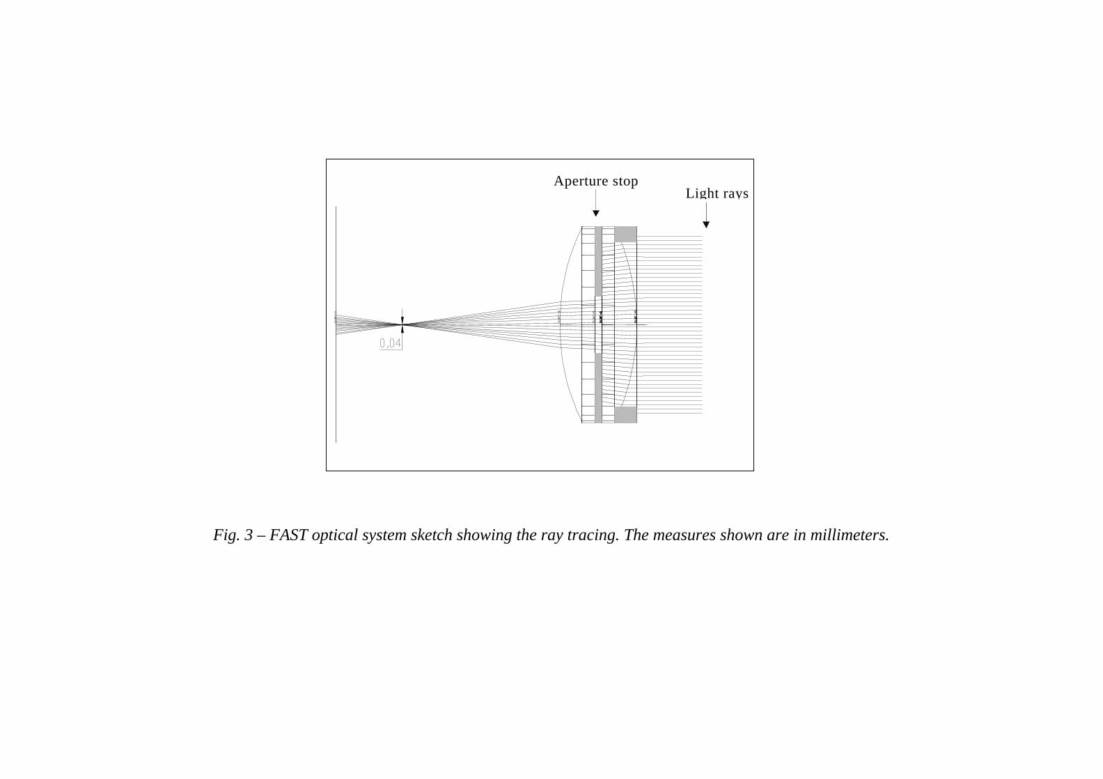
Fig. 3 – FAST optical system sketch showing the ray tracing. The measures shown are in millimeters.
Light raysAperture stop

Fig. 4 – CCD electronics circuit diagram.

Fig. 5 – FAST prototype electronics.

SOFTWARE SEGMENT
On board Star Catalog generation and test
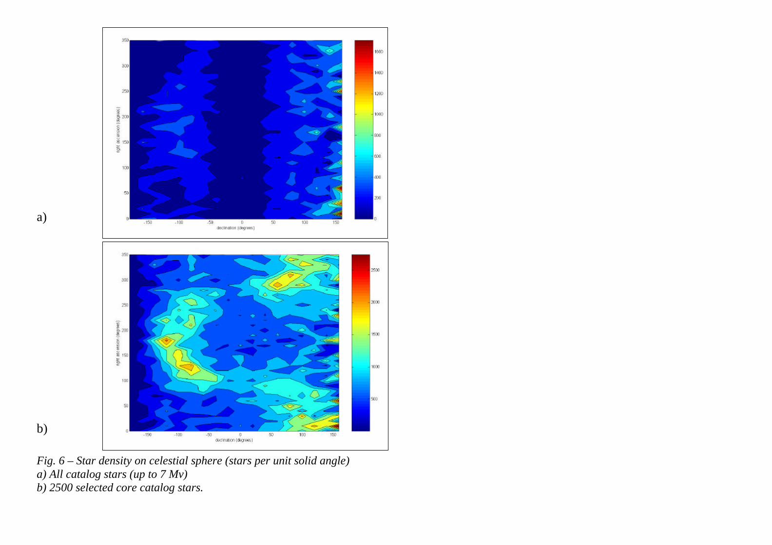
In order to satisfy the full autonomy requirement, 2500-star core catalog has been extracted from the Skymap Catalog [3] to uniformly cover thecelestial sphere and enclose all the sensor detectable stars (visible magnitude <7, proper spectral class, etc.). As a matter of fact, the naturaldistribution of visible stars is far to be spherically uniform because the star density nearby the Milky Way equator is higher than in polar regions.However, Boltzman’s entropy [4] of selected catalog, which tends to zero as the distribution tends to be perfectly uniform, is Φ = 0.00054 instead ofΦ = 0.00850 for the whole catalog up to 7th magnitude.Moreover, the probability has been evaluated of acquiring enough stars in each observed sector, to achieve the desired measurements. The event offinding a star among N uniformly distributed, in a sector of the sky under a given solid angle Q (steradians), can be modeled as a Poisson process ofmean and variance β = (4πN)/Q. Therefore, the probability of finding at least k=4 stars (minimum number of stars to achieve a measure) in a singleFOV is given by:
+++−=≥ −
3211);4(
32 ββββ βekP
In the case of FAST (N=2500 and β=12.132) it results P(k≥4; β) = 0.99633. Because of the non-uniformity in star distribution, increasing the starnumber does not affect the success in recognition.In fig. 6 the contour plots of star densities (number of stars per unit solid angle)are shown either for the whole catalog up to 7th magnitude and for theselected 2500-star catalog. In particular, in the first plot the Milky Way depicts a clearly visible “C shaped” region that has been dramaticallysmoothed in the second plot thanks to the selection process.
a)
b)
Fig. 6 – Star density on celestial sphere (stars per unit solid angle)a) All catalog stars (up to 7 Mv)b) 2500 selected core catalog stars.

FAST Algorithm
Recent studies [5] on star trackers pointed out that a true autonomous sensor is capable of adapting the type and accuracy of attitude measurement tothe spacecraft’s attitude conditions. Therefore FAST provides 3 main operating modes (see fig. 7), divided into 7 sub-modes, to guarantee a goodadaptivity to environmental conditions. These are: High Angular Rate Mode (HAR), Low Angular Rate Mode (LAR) and Safe Mode (SM). Modeand sub-mode transitions are automatic, depending on angular rates, or on command. In particular, HAR to LAR and LAR to HAR transitions areachieved when the angular rate module is below (or above) 0.2°/s. In fact, below this rate stars are recognized by FAST CCD sensor as circular blursinstead of elongated strips.
The main difference between the two modes is the adopted image processing technique. Indeed, in LAR mode FAST outputs both rate and angularmeasurements through a classical two step sequence. The first step is known as “image registration” and is used to detect star position in the frame,with a precision of 1/100 of pixel, centroiding the light distribution of a star over its field pixels. The second step is a template matching algorithm,known as “triplet method”, that permits the identification of observed stars and hence the attitude computation.
Mission phaseAttitudeangles
Angularrates
Attitudevariation
Maximum angularrate
Angular ratesaccuracy
Attitude anglesaccuracy
Acquisitionrate
Rate Reduction Mode(RRM) NO YES
1-4 °/s3600-14400 arcsec/s
0.1-0.5 °/s360-1800 arcsec/s 2 Hz
Attitude MantainanceMode (AMM) YES YES 1-2 °
0.1-0.5 °/s360-1800 arcsec/s
0.03-0.1 °/s108-360 arcsec/s
0.2-0.5 °720-1800 arcsec 2-5 Hz
Slewing Mode(SLM) YES YES -/1-2 °
0.1-0.5 °/s360-1800 arcsec/s
0.03-0.1 °/s108-360 arcsec/s
0.2-0.5 °720-1800 arcsec 2-5 Hz
Normal Mode(NM) YES YES
0.001-0.1 °/s3.6-36 arcsec/s
0.001-0.1 °/s3.6-36 arcsec/s
0.0005-0.1°1.8-360 arcsec 5-10 Hz
Orbit Correction Mode(OCM) As AMM
Safe Mode - RateReduction (SF-RR) As RRM
Safe Mode – Slewing(SF-SL) As SLM
Safe Mode – AttitudeMantainance (SF-AM) YES YES 5-10 °
0.1-0.5 °/s360-1800 arcsec/s
0.03-01 °/s108-360 arcsec/s
0.2-0.5 °720-1800 arcsec 2 Hz
Fig. 7 – Transitions between modes. Table 2 - Three axis controlled platform mission phases.Operation mode Mission phase
Attitudeangles
Angularrates
Attitude anglesaccuracy
Angular ratesaccuracy.
Acquisitionrate
1st acquisitiondelay
Attitude anglesrange
Angular ratesrange
Angular accel.Range
De-Tumbling Mode(DTM)
RRM e SF-RR(faster phases) NO YES -
1 °/s3600 arcsec/s 1 Hz 1 s
< 10 °/s< 36000 arcsec/s
< 0.15 °/s2
< 540 arcsec/s2
Rate Only Mode(ROM)
RRM e SF-RR(slower phases) NO YES -
0.05 °/s180 arcsec/s 2 Hz 1 s
< 2 °/s< 7200 arcsec/s
< 0.15 °/s2
< 540 arcsec/s2
Initial AcquisitionMode (IAM) AMM YES NO
0.1 °360 arcsec - - 1 s -
< 0.2 °/s< 720 arcsec/s
< 0.15 °/s2
< 540 arcsec/s2
Coarse Tracking Mode(CTM)
AMM, SLM,OCM YES YES
0.01 °36 arcsec
0.1 °/s360 arcsec/s 4 Hz 0.2 s
< 2 °< 7200 arcsec
< 0.1 °/s< 360 arcsec/s
< 0.15 °/s2
< 540 arcsec/s2
High Accuracy Mode(HAM) YES YES
0.000139 °0.5 arcsec
0.00055 °/s2 arcsec/s 8 Hz 30 s
< 2 °< 7200 arcsec
< 0.01°/s< 36 arcsec/s Negligible
Robust AcquisitionMode (RAM) SF-SL, SF AM YES YES
0.5 °1800 arcsec
0.5 °/s1800 arcsec/s 1 Hz 1 s
< 10 °< 36000 arcsec
< 1°/s< 3600 arcsec/s
< 0.15 °/s2
< 540 arcsec/s2
Table 3 – Operation modes provided by FAST
HARHAR
LARLAR
SMSM

Angular rates acquisition in HAR mode
When in HAR mode FAST images stars as strips. Thanks to “image segmentation” technique [6], the body reference components of angular rates arederived, which are sufficient for platform de-tumbling and slewing.Using the above mentioned image processing technique, the components of star angular displacements, in image sensor plane, are derived bymeasuring the length and orientation of the strips. This allows a mean square estimate of angular speed to be evaluated.The subsequent images describe the three main steps of the adopted processing technique which are:
a) Image acquisitionb) Binarization & labellingc) Regression segments evaluation
a) b) c)
Fig.8 – Angular rate acquisition processing steps in HAR mode

INDOOR TESTING SYSTEM
Besides procedures for accurate spectral, radiometric and angle measurement calibration, a system for indoor testing of the sensor under theprogrammed operating modes has been developed. It is based on a computer-controlled high-resolution CRT display. Its primary concern is thevalidation of the software routines for template recognition and star identification, the correct timing of the overall software system, and thealgorithms for the measurement of angular velocity.Figs. 9 and 10 depict the test assembly as seen from two different points of view, and fig. 11 reports a sketch of the system.
It consists of a 21” CRT display controlled by a Pentium II PC, to generate the simulated star field, and a collimating optics to make the CRTpixels appear as at infinity. The system set up has been designed in order to make the CRT screen cover the whole sensor FOV. The display and thecomputer video controller are capable of addressing a maximum of 1800 x 1440 pixels at vertical refresh rates up to 160 Hz, depending on theresolution. The refresh rate is adjustable so that the same number of light bursts is emitted from pixels of any area of the screen during the exposuretime. This guarantees the correct acquisition of relative magnitude when several stars are displayed simultaneously in different regions of the screen.
The pixel output luminosity is adjustable over 256 digital levels. The range of levels 10 ÷ 255 [7] produces simulated visual magnitudes at earthsurface varying from 6 to 0, so that more than 200 levels are available in the interval of those detectable by the sensor. In addition, a limitedcapability of simulating stars having different color temperature is also available by varying the RGB components of the addressed pixels. Thetesting facility performances are summarized in table 4.A preliminary series of tests is performed for fine mutual calibration of the overall system, with regards to the star tracker measurements of angularposition and magnitude of the imaged star-like light sources. Subsequent tests of the software procedures require the generation of static anddynamic star fields, in order to check recognition and identification algorithm efficiency [8] and verify some of the sensor capabilities, such asangular velocity measurements or automatic switching between operating modes. In addition, it is possible to test the sensor operation during phasesof a planned mission and include perturbation, such as platform vibrations, partial FOV occultation, observation of the sun or planets.

CRTDisplay area ( H x V ) 406 x 304 mm2
Dot Pitch [Horizontal dotpitch]
0.26 [0.22] mm
Selected [maximum]resolution
1600 x 1200 pixels @60÷90 Hz[1800 x 1350 pixels @60÷75 Hz]
Collimating opticsFocal length 1400 mmDiameter 50.8 mm (2”)PerformancesApparent angular diameter ofa single pixel
< 50 arcsec
Apparent angular separationbetween adjacent pixels
< 40 arcsec
Maximum frame rate 20 frames/s
Table 4 – Testing facility performances.

Star field frames, to be displayed by the high-resolution CRT, are constructed on the basis of the SKY2000 star catalogue [3] in accordance to theplatform pointing, which depends on both mission and mission phase considered.Dynamical simulations are performed by displaying accurately time-tagged star field frames, to validate angular velocity measurements and FASTsoftware routine efficiency and timing.
Fig. 9 – Test assembly (CRT side view)

Fig. 10 – Test assembly (FAST side view)

Fig. 11 – Testing facility sketch
Startracker
A Bfcoll
2.0 m
CRTCollimating Optics
A+B ≤ 0.5 m
Optical Bench

CONCLUSIONS
An innovative star tracker has been described, which is under development thanks to the financial sponsorship of Consortium Technapoli, Napoli,Italy, in the mainframe of a project of technology transfer between research centers and local aerospace industries. This system is aimed at satisfyingthe requirements of autonomy and flexibility, in order to be used as the only attitude sensor on-board and applied to the widest range of spacemissions. A brief description of the hardware, software and testing has been given.
Further activities will be addressed to improve the realized system. In particular, the goal of this activity is the realization of the space-qualifiedmodel of the sensor, performing in-house qualification tests. Furthermore hardware evolution will deal with the development of a multi-head systemin order to notably decrease the occurrence of misidentification errors and simultaneously increase the acquisition rate.
REFERENCES1.W. J. Smith, Modern Optical Engineering, Mc Graw Hill Inc. (1990);2.M. M. Birnbaum, Spacecraft Attitude Control Using Star Field Trackers, Acta Astronautica 39, 9-12, 763-773 (1996).3.J.R. Myers, C.B. Sande, A.C. Miller, W.H. Warren Jr., and D.A. Tracewell, SKY2000 Master Star Catalog – Star Catalog Database; Goddard
Space Flight Center, Flight Dynamics Division (contract NAS5-31000 ), (1997);4.J.D. Vedder, Star Trackers, Star Catalogs, and Attitude Determination: Probabilistic Aspects of System Design. Journal of Guidance, Control and
Dynamics 16, 3, 498-504 (1993);5.European Space Agency, Work Statement for the Study on Autonomous Star Tracker Algorithms, ESTEC – WSC (RF: WSC-97-WS-AST) (1997);6.W.K. Pratt, Digital Image Processing, 2nd ed., John Wiley and Sons Inc., New York (1991);7.Typical Monitor Luminance Values for Photo YCC Luma Value, Kodak Publication PCD-102, (1995);8.Padget, K. Kreutz-Delgado, and S. Udomkesmalee, Evaluation of Star Identification Techniques, J. Guidance, Control, and Dynamics, 20, 2, 259-267 (1997).