A Four-Wing Butterfly Attractor from a Fully Autonomous System
7
International Journal of Bifurcation and Chaos, Vol. 13, No. 10 (2003) 3093–3098 c World Scientific Publishing Company A FOUR-WING BUTTERFLY ATTRACTOR FROM A FULLY AUTONOMOUS SYSTEM A. S. ELWAKIL * Department of Electrical & Electronic Engineering, University of Sharjah, P.O. Box 27272, Emirates S. ¨ OZO ˇ GUZ Istanbul Technical University, Faculty of Electrical-Electronics Engineering, 80626, Maslak, Istanbul, Turkey M. P. KENNEDY Department of Microelectronic Engineering, University College Cork, Cork, Ireland Received May 10, 2002; Revised June 11, 2002 A novel system of nonlinear differential equations is proposed. This system is capable of generat- ing a complex four-wing butterfly chaotic attractor by relying on two embedded state-controlled binary switches. Hence, the system is fully autonomous and does not require external forcing to create this attractor. Furthermore, digital logic operations (e.g. AND/OR) performed on the outputs of the two switches are permitted and effectively alter the dynamics of the system. Our findings are validated via experimental results. Keywords : Chaos; Lorenz system; butterfly attractor; chaotic oscillators. 1. Introduction The Lorenz system of differential equations which produces the well-known butterfly chaotic attrac- tor [Lorenz, 1963] has served as a prototype model for studying chaotic behavior for quite a long time [Sparrow, 1982]. Recently, there has been some re- newed interest in the dynamics of this system par- ticularly as it has been discovered that new sets of equations, not topologically equivalent to the origi- nal system, can maintain its characteristic butterfly attractor [Chen & Ueta, 1999; Ueta & Chen, 2000]. In [Baghious et al., 1993] and [Elwakil & Kennedy, 2001], Lorenz-type systems which are multiplier-free were proposed. It was particularly shown in [Elwakil & Kennedy, 2001] that the con- tribution to the chaotic dynamics of multiplying two internal state variables can be reproduced by multi- plying one of these variables with a state-controlled binary switching constant. Such a finding signifi- cantly simplifies and facilitates circuit realizations of Lorenz-type systems [ ¨ Ozoˇ guz et al., 2002]. In [Elwakil et al., 2002], a new dual-mode com- plementary Lorenz-type system was proposed. This system is free from the positive Z constraint, which is inherent in the original Lorenz system and also in the systems of [Chen & Ueta, 1999; Ueta & Chen, 2000; Baghious et al., 1993] and [Elwakil & Kennedy, 2001]. The equations describing this system are: ˙ X = a(Y - X ) (1a) ˙ Y ∓ = ∓KZ (1b) * Permanent address: Reactor Department, Egyptian Nuclear Research Centre, Inshas, Egypt. 3093
Transcript of A Four-Wing Butterfly Attractor from a Fully Autonomous System

November 7, 2003 9:0 00840
International Journal of Bifurcation and Chaos, Vol. 13, No. 10 (2003) 3093–3098c© World Scientific Publishing Company
A FOUR-WING BUTTERFLY ATTRACTOR FROM
A FULLY AUTONOMOUS SYSTEM
A. S. ELWAKIL∗
Department of Electrical & Electronic Engineering,
University of Sharjah, P.O. Box 27272, Emirates
S. OZOGUZIstanbul Technical University, Faculty of Electrical-Electronics Engineering,
80626, Maslak, Istanbul, Turkey
M. P. KENNEDYDepartment of Microelectronic Engineering,
University College Cork, Cork, Ireland
Received May 10, 2002; Revised June 11, 2002
A novel system of nonlinear differential equations is proposed. This system is capable of generat-ing a complex four-wing butterfly chaotic attractor by relying on two embedded state-controlledbinary switches. Hence, the system is fully autonomous and does not require external forcingto create this attractor. Furthermore, digital logic operations (e.g. AND/OR) performed on theoutputs of the two switches are permitted and effectively alter the dynamics of the system. Ourfindings are validated via experimental results.
Keywords : Chaos; Lorenz system; butterfly attractor; chaotic oscillators.
1. Introduction
The Lorenz system of differential equations whichproduces the well-known butterfly chaotic attrac-tor [Lorenz, 1963] has served as a prototype modelfor studying chaotic behavior for quite a long time[Sparrow, 1982]. Recently, there has been some re-newed interest in the dynamics of this system par-ticularly as it has been discovered that new sets ofequations, not topologically equivalent to the origi-nal system, can maintain its characteristic butterflyattractor [Chen & Ueta, 1999; Ueta & Chen, 2000].
In [Baghious et al., 1993] and [Elwakil &Kennedy, 2001], Lorenz-type systems which aremultiplier-free were proposed. It was particularlyshown in [Elwakil & Kennedy, 2001] that the con-tribution to the chaotic dynamics of multiplying two
internal state variables can be reproduced by multi-plying one of these variables with a state-controlledbinary switching constant. Such a finding signifi-cantly simplifies and facilitates circuit realizationsof Lorenz-type systems [Ozoguz et al., 2002].
In [Elwakil et al., 2002], a new dual-mode com-plementary Lorenz-type system was proposed. Thissystem is free from the positive Z constraint, whichis inherent in the original Lorenz system and alsoin the systems of [Chen & Ueta, 1999; Ueta &Chen, 2000; Baghious et al., 1993] and [Elwakil& Kennedy, 2001]. The equations describing thissystem are:
X = a(Y − X) (1a)
Y∓ = ∓KZ (1b)
∗Permanent address: Reactor Department, Egyptian Nuclear Research Centre, Inshas, Egypt.
3093

November 7, 2003 9:0 00840
3094 A. S. Elwakil et al.
Z± = ±|X| ∓ 1 (1c)
and
K =
1 X ≥ 0
−1 X < 0(1d)
where a is a constant. Two complementary modes ofoperation; S(−, +) = (X, Y−, Z+) and S(+, −) =(X, Y+, Z−) are admitted. Switching between thesetwo modes via an external pulse-train creates acomplex (four-wing) butterfly attractor. It was thecomment of one of the reviewers of [Elwakil et al.,2002] that in this case the system can no longerbe considered autonomous despite the fact that theeigenvalue patterns of S(−, +) and S(+, −) remainunchanged and are independent of this pulse-train.
It is therefore the aim of this work to introducea fully autonomous system capable of generating afour-wing butterfly attractor without need for anexternal switching force. Such a challenging taskhas been made possible by incorporating two state-controlled binary switches. We demonstrate that bi-nary logic operations can also be performed on theoutputs of these two switches and fedback to thesystem to obtain a three-wing butterfly.
2. Proposed System
We propose the following system of equations:
X = (K1 + ε)X − K2Y (2a)
Y = mK2X − K1Y − n (2b)
Z = X − nZ (2c)
where ε, n and m are all constants. The embed-ded state-controlled binary switches are K1 and K2
given respectively by:
K1 =
1 Y ≥ 0
−1 Y < 0and K2 =
1 Z ≥ 0
−1 Z < 0
(3)
Alternatively, these two switches can be written asK1 = sgn(Y ) and K2 = sgn(Z). The above systemacquires four equilibrium points which are given by:
(x0, y0, z0)=n
m−1−εK1
(
K2, ε+K1,K2
n
)
=
n
m−1−ε
(
±1, ε+1,±1
n
)
Y ≥0
n
m−1+ε
(
±1, ε−1,±1
n
)
Y <0
(4)
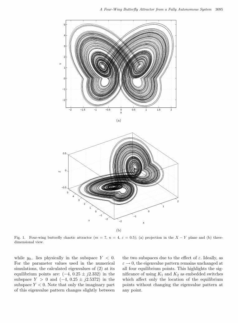
It is clear that these equilibrium points are symmet-rically located only within the two subspaces Y ≶ 0while they are unsymmetrically located within theX ≶ 0 and Z ≶ 0 subspaces. The positions of theseequilibria can be seen in Fig. 1(a), which representsa projection in the X−Y plane of the chaotic attrac-tor obtained by numerically integrating (2) using afourth-order Runge–Kutta algorithm with a 0.001step size. The parameters m, n and ε were set to 7,4 and 0.5, respectively. For these values, the equi-librium points are 1
11(±8, 12, ±2) for Y > 0 and
1
13(±8, −4, ±2) for Y < 0. For clarity, the chaotic
attractor, constructed in the X−Y −Z space, is alsoshown in Fig. 1(b). We hereafter refer to this attrac-tor as the four-wing butterfly. It is evident that thesurface areas of the two wings located in the Y > 0subspace (upper wings) are larger than those of thetwo wings located in the Y < 0 subspace (lowerwings) due to the unsymmetrically located equilib-rium points with respect to X ≶ 0 and Z ≶ 0.Note from (4) that n is a volume enlargement fac-tor. In particular, the volume in space occupied bythe butterfly can be expanded by increasing the dis-tance between all equilibrium points which is possi-ble when increasing n. Indeed, we have intentionallyadded this parameter to the system in order to facil-itate the experimental observation of the butterflyattractor.
To understand the sequence behind developingthis system, we recall that the linearized dynamicsof a second-order quadrature oscillator around itsunstable equilibrium point are modeled by:
(
X
Y
)
=
(
a11 + ε a12
a21 −a11
)(
X
Y
)
(5)
where ε is an error compensating parameter whichis used to guarantee the start of oscillations. Ideally,at ε = 0, a pure imaginary eigen pair is born and thefrequency of oscillation is ω0 =
√
−a211
− a12a21.For, ε > 0, the eigen pair is shifted slightly into theright half plane and an external nonlinear mecha-nism is necessary to stabilize the oscillation growth.
Now, by comparing (5) with the dynamics inthe X−Y plane of (2) we note that a11 = K1, a12 =−K2 and a21 = mK2. This indicates that a quadra-ture oscillator with a center frequency of oscillationgiven by ω0 =
√
mK22− K2
1− εK1 =
√m − 1 ∓ ε
governs the dynamics of (2) in the X−Y plane. Ev-idently, the constraint m > 1 + ε must be satisfied.Recalling (4), satisfying this constraint also guaran-tees that y0+ lies physically in the subspace Y > 0
November 7, 2003 9:0 00840
A Four-Wing Butterfly Attractor from a Fully Autonomous System 3095
−2 −1.5 −1 −0.5 0 0.5 1 1.5 2
−2
−1
0
1
2
3
4
5
X
Y
(a)
−2
−1
0
1
2
−2
−1
0
1
2
3
4
5
−0.5
0
0.5
XY
Z
(b)
Fig. 1. Four-wing butterfly chaotic attractor (m = 7, n = 4, ε = 0.5); (a) projection in the X − Y plane and (b) three-dimensional view.
while y0− lies physically in the subspace Y < 0.For the parameter values used in the numericalsimulations, the calculated eigenvalues of (2) at itsequilibrium points are: (−4, 0.25 ± j2.332) in thesubspace Y > 0 and (−4, 0.25 ± j2.5372) in thesubspace Y < 0. Note that only the imaginary partof this eigenvalue pattern changes slightly between
the two subspaces due to the effect of ε. Ideally, asε → 0, the eigenvalue pattern remains unchanged atall four equilibrium points. This highlights the sig-nificance of using K1 and K2 as embedded switcheswhich affect only the location of the equilibriumpoints without changing the eigenvalue pattern atany point.

November 7, 2003 9:0 00840
3096 A. S. Elwakil et al.
−2 −1.5 −1 −0.5 0 0.5 1 1.5 2
−2
−1
0
1
2
3
4
5
X
Y
Fig. 2. Three-wing butterfly attractor when K1 in (3) is replaced by [K1 AND K2] (m = 7, n = 4, ε = 0.5).
It is worth noting that in (2) we have alsoadopted a thresholding mechanism similar to thatin [Elwakil et al., 2002] which allows the state vari-able Z to swing both in the negative and positivehalf-spaces. Z will change its sign when Z is equal toX/n, which means that at every equilibrium pointsuch a sign change will take place. Since K2 is con-trolled by the sign of Z, the link between the subsys-tem (2) and the quadrature oscillator in the X − Yplane becomes clear.
It is also worth noting that since K1 and K2 arebinary switches, digital logic operations can be per-formed on them and the output reintegrated intothe system. For example, if the operation (K1 ANDK2) is performed on (3) and the output is used toreplace K1 in (2), the three-wing butterfly shown inFig. 2 is obtained. The mirror image around the Yaxis of this attractor is obtained if the logic opera-tion is OR instead of AND.
3. Experimental Verification
A circuit realizing the proposed system is shown inFig. 3 where the involved active elements are cur-rent feedback operational amplifiers (CFOAs) [Soli-man, 1996]. The voltages across the three capacitors
(CX , CY , CZ) correspond to the respective statevariables of the system whereas resistors Rm, Rn
and Re are respectively used to tune the parame-ters m, n and ε in (2). VR is a reference DC voltageand analog switches are used to implement bothK1 and K2. The controlling signals for these analogswitches and their compliments are generated fromtwo comparators (not shown in Fig. 3), controlledby VY , VZ , and additional CMOS inverters. The re-maining resistors and CFOAs in the circuit are usedto perform necessary voltage to current conversions.
By setting CX = CY = CZ = C, R1 = R2 =R3 = R4 = R5 = R, Rm = R/m, Re = R/ε,Rn = R/n, X = VX/VR, Y = VY /VR, Z = VZ/VR
and scaling time with respect to RC, it can be ver-ified that the circuit in Fig. 3 realizes (2).
We have constructed this circuit using discretecomponents; the CFOAs were all AD844 chips, thecomparators used to generate the binary control sig-nals for K1 and K2 were LM311 chips while theircompliments K1 and K2 were generated using 4007CMOS inverters. All the active elements were bi-ased with ±5V and all the capacitors were taken as10 nF. The resistor values were set to R = 5.1 kΩ,Rm = 710 Ω, Rn = 1.5 kΩ and Re = 10 kΩ, corre-sponding to m = 7.18, n = 3.4 and ε = 0.51. Thereference voltage VR was kept at −1 V.

November 7, 2003 9:0 00840
A Four-Wing Butterfly Attractor from a Fully Autonomous System 3097
Fig. 3. Circuit realization of the proposed system (2).
(a) (b)
Fig. 4. Experimental VX−VY observations (X axis: 0.15 V/div, Y axis: 0.3 V/div); (a) four-wing butterfly and (b) three-wingbutterfly.
Figure 4(a) represents the observed VX − VY
four-wing butterfly attractor. In order to obtain thethree-wing attractor of Fig. 2, the control signalsK1 and K1 (see Fig. 3) were replaced by (K1 ANDK2) and its compliment, respectively. These signalswere generated using CMOS NAND gates. The ob-served VX − VY trajectory in this case is shown inFig. 4(b).
4. Conclusion
We have proposed a fully autonomous systemcapable of generating a complex four-wing but-terfly attractor. The core idea behind the devel-opment of the system is the use of embeddedstate-controlled binary switches to locate differentequilibrium points without affecting the eigenvaluepattern of the linearized system at each of these

November 7, 2003 9:0 00840
3098 A. S. Elwakil et al.
equilibrium points. It is worth noting that a nonau-tonomous binary source, which might represent adata sequence, can be easily integrated into the sys-tem through ORing or ANDing with K1 or K2.
References
Baghious, E. H. & Jarry, P. [1993] “Lorenz attractor fromdifferential equations with piecewise-linear terms,”Int. J. Bifurcation and Chaos 3, 201–210.
Chen, G. & Ueta, T. [1999] “Yet another chaoticattractor,” Int. J. Bifurcation and Chaos 9,1465–1466.
Elwakil, A. S. & Kennedy, M. P. [2001] “Construction ofclasses of circuit-independent chaotic oscillators usingpassive-only nonlinear devices,” IEEE Trans. Circuits
Syst.-I 48, 289–307.Elwakil, A. S., Ozoguz, S. & Kennedy, M. P. [2002]
“Creation of a complex butterfly attractor using anovel Lorenz-type system,” IEEE Trans. Circuits
Syst.-I 49, 527–530.Lorenz, E. N. [1963] “Deterministic nonperiodic flow,”
J. Atmos. Science 20, 130–141.Ozoguz, S., Elwakil, A. S. & Kennedy, M. P. [2002] “Ex-
perimental verification of the butterfly attractor ina modified Lorenz system,” Int. J. Bifurcation and
Chaos 12, 1627–1632.Soliman, A. M. [1996] “Applications of the current feed-
back operational amplifiers,” Anal. Integ. Circuits
Sign. Process. 11, 265–302.Sparrow, C. [1982] The Lorenz Equations: Bifurcations,
Chaos, and Strange Attractors (Springer-Verlag, NY).Ueta, T. & Chen, G. [2000] “Bifurcation analysis of
Chen’s attractor,” Int. J. Bifurcation and Chaos 10,1917–1931.