DEVELOPING AN ELECTRONIC TRACKING SYSTEM FOR SOLAR COLLECTORS
14
DEVELOPING AN ELECTRONIC TRACKING SYSTEM FOR SOLAR COLLECTORS Attar, M.Z. Assist. Prof., Dep. Ag. Eng . Ain-Shams U., Cairo, Misr (Egypt). +20113232199; fax 202 – 44444460; email: [email protected] ABSTRACT An increase of solar power harvesting units efficiency was obtained by using an electronic solar tracking system. The tracking system uses infra- red sensors derived by an electronic circuit to detect the solar incidence angle, which produces a controlling signal to run a dual direction DC motor. A directional solar unit is actuated by the motor throughout the daylight duration. The solar tracking system accuracy to detect solar rays inclination angle varied from 6-7°. Laboratory and field tests on photovoltaic panel showed an increase in power gain by 32.29% compared with non-tracked system. Key words: solar energy, electronic solar tracking, photovoltaic panel. INTRODUCTION he world faces serious energy shortages with the ever- increasing world energy consumption from 1 to 2% a year, and increasing future requirements to 10% by year 2020 (Pimentel et al., 1994). Domestic fossil energy supplies combustion is the major contributor to increasing pollutant concentration in the environment, which affect food production and process. In order to supply enough power for agricultural applications, large photovoltaic (PV) arrays are required. PV overall performance can be attributed to the efficiency of the cell, and the intensity of the source radiation on the cell. The materials used in the manufacture of solar cells restrict the overall performance. Instead of increasing the size of the PV arrays, it is more beneficial to increase the performance of the solar cell, it is an easier process to increase the amount of source radiation that is received at the cell by T
Transcript of DEVELOPING AN ELECTRONIC TRACKING SYSTEM FOR SOLAR COLLECTORS

DEVELOPING AN ELECTRONIC TRACKING SYSTEM FOR
SOLAR COLLECTORS
Attar, M.Z.
Assist. Prof., Dep. Ag. Eng .
Ain-Shams U., Cairo, Misr (Egypt). +20113232199; fax 202 – 44444460; email: [email protected]
ABSTRACT
An increase of solar power harvesting units efficiency was obtained by
using an electronic solar tracking system. The tracking system uses infra-
red sensors derived by an electronic circuit to detect the solar incidence
angle, which produces a controlling signal to run a dual direction DC
motor. A directional solar unit is actuated by the motor throughout the
daylight duration. The solar tracking system accuracy to detect solar rays
inclination angle varied from 6-7°. Laboratory and field tests on
photovoltaic panel showed an increase in power gain by 32.29%
compared with non-tracked system.
Key words: solar energy, electronic solar tracking, photovoltaic panel.
INTRODUCTION
he world faces serious energy shortages with the ever-
increasing world energy consumption from 1 to 2% a year, and
increasing future requirements to 10% by year 2020 (Pimentel et
al., 1994). Domestic fossil energy supplies combustion is the major
contributor to increasing pollutant concentration in the environment,
which affect food production and process. In order to supply enough
power for agricultural applications, large photovoltaic (PV) arrays are
required. PV overall performance can be attributed to the efficiency of the
cell, and the intensity of the source radiation on the cell. The materials
used in the manufacture of solar cells restrict the overall performance.
Instead of increasing the size of the PV arrays, it is more beneficial to
increase the performance of the solar cell, it is an easier process to
increase the amount of source radiation that is received at the cell by
T

2
focusing the sun's incident rays onto a rigid array, or to tracking the sun's
path using a dynamic tracking system, or both together.
The aim of the study is to increase the efficiency of solar energy
harvesting systems by using an efficient, low cost electronic solar
tracking system. It is necessary to select the most suitable type of optical
detector (sensors arrangement), building circuit for measuring and
controlling solar radiation incident detection angle, using an appropriate
motion source and transmission set, calculating power gain in fixed and
tracked PV units, and cost analysis work. Results show increase of total
harvested solar energy up to 32.29% (under the experiment conditions)
and the tracking system was efficient in most environmental changes
according to an infra-red detector used to detect thermal sun rays, which
can perform in cloudy conditions. The use of solar tracking system
recommended is for expanding the use of PV modules.
Photovoltaic cells: produce electricity when sunlight excites electrons in
them. However, improvements are needed in the photovoltaic cells to
make them economically competitive (Moore, 1992).
The solar constant 1367 W/m2 is the average radiation intensity over the
earth atmosphere in the middle earth distance from the sun. The
maximum radiation intensity is up to 1100 W/m2 on the earth surface
during the sunny day. The efficiency of the best semiconductor
photovoltaic solar panels ranges from 15% to 20%. It is possible to obtain
160 to 200 W per square meter area (Del Chiaro, et. al., 2004).
Elliot Larard in 1998 designed a number of dynamic sun tracking
systems by use of light sensitive pyramid-shape solar cell sensors set at
45° angles. And two independent stepper motors controlling the position
of PV array. The designs were plagued with problems concerning the
rotation axis, variation in sensor performance with temperature, stepper
motor controlling circuits and software were complicated and expensive,
sensor alignment and weight problems. Hamilton in 1999, developed the
Larard's tracking system (Hamilton, 1999).
Gadewadikar (2004) used a stepper motor for controlling the position of
solar energy collector, and software included the positioning of collectors
through stepper motor, data acquisition and processing by a
microprocessor.

3
Three main types of sun trackers exist: passive, microprocessor and
electro-optically controlled units. Passive systems track the sun without
any electronic controls or motors, these are simple but can only provide
moderately accurate tracking. Microprocessor controlled sun tracking
units use mathematical formulae to predict the sun's location and need not
sense the sunlight. This type of tracker is highly accurate but requires a
very precise installation, often difficult to achieve. Electro-optical
trackers give very good results during good weather conditions (Roth et
al., 2005). Awady and Attar (2007) present an electronic solar tracking
system. And this study aims to evaluate the design and performance of the
presented solar tracking system.
Materials and Methods
The electronic sun tracking system was tested through year 2005-2006
at the Egyptian Nuclear Power Station located at Enshas “30.01 ,”انشاص°
latitude, and 31.14° longitude, sun declination angle of 23.177°, solar
altitude 68.98°, sun rise at 05:01, and sun set at 18:56”. The path of the
Sun through the sky changes significantly throughout the year, so the
position of the sun changes both hourly and seasonally. Maximum solar
energy was obtained when the sun rays strike normally at the solar power
harvesting unit. The relation of solar rays inclination angle and power
gain were illustrated by equation 1. I = S cos Z , .................................................................................. Equation 1
where I: is insolation, S:1000 W/m2 , and Z: Zenith Angle.
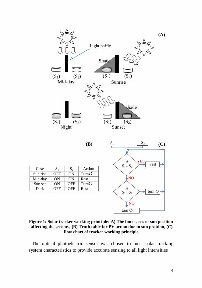
Solar tracker working principle
Electro-optical solar tracking system is composed of one pair of anti-
parallel photo-detectors. The photo-detectors were separated by
illumination baffle which are, by equal intensity of illumination of both
elements when solar rays restrict their surface in right angle
(fig.1).Sensor-1 (S1), and sensor-2 (S2), are electrically balanced so that
there is either no or negligible control signal on a driving motor. By
differential illumination of electro-optical sensors due to sun rays tilt
angle, differential control signal occurs which is used to drive a DC motor
and to drive the sensing elements attached to the collector unit in such
direction where illumination of electro-optical sensors is equal and
balance is restored.
4
Case S1 S2 Action
Sun rise OFF ON Turn
Mid-day ON ON Rest
Sun set ON OFF Turn
Dark OFF OFF Rest
Figure 1: Solar tracker working principle: A) The four cases of sun position
affecting the sensors, (B) Truth table for PV action due to sun position, (C)
flow chart of tracker working principle.
The optical photoelectric sensor was chosen to meet solar tracking
system characteristics to provide accurate sensing to all light intensities
shade
Shade
Sunrise Mid-day
Sunset Night
(S1) (S2)
(S1) (S2) (S2) (S1)
(S1) (S2)
S1 S2
is
S1 = S2
is S1 > S2
rest
turn
NO
NO
YES
turn
(A)
(C) (B)
Light baffle

5
during the day, to use power sources normally available in the field, and
to be –relatively- at low cost. Infra-red sensors (IR) and light dependent
resistor (LDR) illustrated in fig.2A and fig.2B, were tested to determine
their characteristics under desired system performance.
Pin 1:Vout
Pin 2 :GND
Pin 3:Vcc (+5V)
Figure 2:A) IR and B) LDR photo-electric sensors.
sensor Response to solar rays inclination angle:
A set of sensors was built to determine the accuracy for detecting solar
rays inclination angle as shown in fig.3. The set was made from acrylic
base with angle measurement index. A pivot sensors baffle with
changeable length was set to turn right and left faces the incoming light
rays. Measurements were taken to obtain optimal positioning performance
by finding the proper baffle length "L", and sensor alignment (distance
"D", angle°) as shown in fig.4.
Figure 3: Measuring set for sensors response to sun rays inclination angle
with sensor three inclination angles.
Light source
Sensor baffle
IR sensor
Angle index
A B

6
Figure 4: Sensor measuring parameters: Baffle length "L", and sensors
alignment: distance "D" , Angle .
A lux meter (Extech instruments meter) model 407026, 3½ digit (2000
count LCD) 50000 lux, color corrected photo diode, accuracy ± 4%+2
digits was used to measure light intensity under laboratory condition with
tungsten bulb light source at 434 lux.
Sensor shield
To increase the accuracy of the solar tracking system. A sensors shield
was used to allow only the direct sun radiation to pass through a thin
vertical entrance “1mm width” as shown in fig.5 , while blocking
scattered, and diffused radiation.
Dim in “mm”
Figure 5: Schematics assembly of photo-sensor shield and solar rays baffle.
L
D
IR sensor IR sensor
baffle
=135° =90° =180° IR sensor
baffle

7
Motion direction control circuit
Circuit controls motion direction of a DC “Direct Current” motor by
changing the polarity of circuit output by an electro-mechanical relays
“varied according to load”. Fig.6 illustrates the working principle of
direction control unit in all working cases. Over-load protection was
established by using a specific resistance. A resistance value was
calculated according to equations 2,3. ...................................................................................... Equation 2
..................................................................................... Equation 3
Where, R is the resistance value “ohm”, V electrical potential “Volts”,
and I current “amperes”. Measured circuit load (resistance 36Ω), which
worked by potential at “9V” from equation 2, I =0.25 A. So, over-load
protection can be done with connecting circuit relays “14Ω” with
resistance R4=22Ω. From equation 3, R4 rated power equals 2.25 W.
Figure 6: Schematic diagram for the electronic tracking system circuit.
Tested photovoltaic panel specifications (PV)
Electronic solar tracking system was tested on two groups of PV (fixed
and tracked of sun position) each containing six module "Shell SM55
"PowerMax®" mono-crystalline silicon solar cells". The Shell SM55
module can generate a peak power of 55W at 17.4 volt (Shell Solar
R2
R2
R4
R4
DC
motor
NC
ND
NC
ND
NC
ND
NC
ND
Relay (1)
Relay (2)
R1
R1
R3
R3
Q1
Q1
Q2
Q2
S2
S1

8
manual, 2002). Fig.7, illustrates the PV panel and tracking system attached
to it.
Figure 7: PV panel set with the electronic tracking system.
PV Motion actuators (the DC motor)
Modulating Spring Return Actuators by Joventa Comp. was used to
drive the PV panel. The modulating actuators have the ability to change
motion direction with maximum torque of 16Nm at power 5.5W, through
changing DC motor electrical polarity (fig.8).
Figure 8: Illustration PV motion actuators.
Net electrical power was estimated form calculating area under curve of
power-time, produced for the PV panel for both of fixed and tracked PV
modules. Integration was performed on the obtained function according to
equations 4,5.
Solar tracker sensing unit
Motion actuator DC motor Photovoltaic panel
Frame stand

9
............................................................................ Equation 4
................................................................. Equation 5
where E: is the energy in Watts, x: is the time "t", and f(x): the power
"P".
Results and discussions
Results have proved that constructing the solar tracking sensor with
baffle length of 4cm, and sensor spacing at 0cm in-between, with sensor
tilting angle of 90° "vertical position" would give optimal response when
sun rays inclined 6-7° over the sensor (fig.9).
Figure 9: Relation of IR sensor response to sensor position at varied baffle
length.
Sensor shielded was found to play an important rule in preventing
sensor from being saturated due to scattered light form the surroundings.
Another roule for using sensor shield is to protect the sensor form
environmental contaminants such as rains and dust (fig.10).
Figure 10: IR sensor respons at different tilting angles (0°, 45°, and 90°).

10
IR sensor, according to the results and visual inspection was the most
approparte choice compared with other sensor "LDR sensor" for fast
response to the fluctuated environmental conditions, and for the higher
resistance change due to detected solar radiation, compared with LDR
sensor (fig.11). IR sensors produce the optimal electrical potential for
driving the circuit at 0.6V. The IR sensor which has the ability to detect
IR lights in the range of thermal rigone will be a good choice for
eleminating the effect of clouds and dust which prevents the other
waveform from reaching the sensor, and benefit in orientation the system
toward the important portion of solar rays falling in the thermal region.
Figure 11: Comparasone between LDR and IR sensor resistance response to
different illumination levels.
The net gain of electrical power form fixed, and tracked PV panel was
obtained (fig.12). The fixed PV panel produced a varied electrical power
in relation to light intenstiy fluctuating during the day, compared to fixed
PV panel.
A solar tracked PV panel performs better in increasing the total
harvested electrical power by 32.29%, by keeping the panel facing the sun
all the time.

11
Figure 12: Net electrical power output for fixed and tracked PV module.
Conclusions and recommendations
The energy from the sun can serve many purposes; one of them is to
generate electricity through PV panel. PV can meet electricity demand at
remote areas where there is no connection to the electricity grid,
households, powering water pumps, refrigerators, and for power
generators. Using electronic tracking system increases the efficiency of
water solar collector, solar dryers of agricultural materials, maturing
compost, shading animal buildings, and control the environment of the
green houses.
Using solar tracking system can improve the total efficiency of the PV
panels, which ranges between 15 to 20 %. With no sophisticated or new
arrangement to develop the current working units.
For optimum performance of harvesting solar power, the tracking
sensing element must be aligned to each other, and with the solar rays
baffle between them with 4 cm length, each facing the opposite side in a
vertical orientation to achieve tracking accuracy of 6-7° of detecting solar
rays.
For peak performance, a solar module should face the brightest part of
the sky. Tracking system may be utilized to improve system performance
(by up to 32.29%).

12
References
Awady, M.N.; and M.Z.; Attar, 2007, An electronic solar tracking
system, Acad. Sci. Tech. patent No. 23899.
Del Chiaro, B.; T. Dutzik; and J. Vasavada, 2004, The economics of
solar homes in California: how residential photovoltaic incentives
can pay off for homeowners and the public. Report, Environ.
California Res. Policy Centre: 1-28.
Elliot; L., 1998, Solar array system, Eng. B.Sc. thesis, Elec. Eng. Dept.,
Queensland Univ.:1-15.
Gadewadikar; J.E., 1997, Microprocessor based solar tracking system
using stepper motor, S.G.S. Inst. Tech. and Sci. Project, Indore :1-7.
Hamilton; S.J., 1999, sun-tracking solar cell array system, B.Sc. thesis. ,
Elec. Eng. Dept., Queensland Univ.: 13, 19-34,42.
Moore; T., 1992, High hopes for high-power solar, EPRI J., 17(8): 16-25.
P. Roth; A. Georgiev; and H. Boudinov, 2005, Cheap two axis sun
following device, Energy Conversion&Management, 46:1179–
1192.
Pimentel, D.; M. Herdendorf; S. Eisenfeld, L. Olanden M.
Carroquino, C. Corson, J. McDade Y. Chung, W. Cannon, J.
Roberts, L. Bluman, and J. Gregg, 1994, Environ. Eco. issues,
Ecol. Econ., 9: 201-219.
Shell solar manual, 2002, shell SM55 photovoltaic solar module,
Helmond the Netherlands: www.shellsolar.com.

الشمسية للمجمعات لكترونىإ تتبع نظام تطوير
العطار م.ز. جامعة عين شمس –كلية الزراعة –قسم الهندسة الزراعية –مدرس
المستخلص
السبقطت الشوس أشؼت حؼبهذ ػنذ الشوسيت الوجوؼبث بىاسطت الوىلذة الطبقت كويت حخشايذ
ودذاث كفبءة رفغ إلى يهذف إلكخزونى نظبم حطىيز حن الشوسيت. للوجوؼبث االهخصبص وسطىح
وودذة كهزوضىئيت بوسخشؼزاث هشودة إلكخزونى، حىجيو نظبم ببسخخذام الشوسيت الطبقت حجويغ
كهزبى. بوذزك حؼول آليت حىجيو
أشبره وإصذار الشوسيت، لألشؼت السقىط ساويت حذذيذ ػلى الكهزوضىئيت الوسخشؼزاث حؼول
سطخ حىجو والخى الشوسى. الوجوغ وسطخ الشوسيت األشؼت حؼبهذ ػذم دبلت فى الخىجيو لىدذة حذكن
أنىاع هن ػذد تهقبرن حن ػليو. السبقطت الشوسيت واألشؼت ػوىديب وضؼب ليخخذ الشوسى الوجوغ
(IR الذوزاء حذج األشؼت وهسخشؼزاث ، LDRكهزوضىئيت هقبوهت ) الكهزوضىئيت الوسخشؼزاث
دلج الشوسيت. األشؼت سقىط ساويت ػلى الخؼزف فى أفضلهب لخقصى الوخخلفت الخجهيشاث هن وػذد ،
دذود فى حقغ يوحىج بذقت السبقطت الشوسيت األشؼت اسخشؼبر ػلى الخىجيو نظبم هقذرة ػلى النخبئج
حفضيل وػذم الذوزاء. حذج ببألشؼت حؼول الخى الكهزوضىئيت الوسخشؼزاث اسخخذام ػنذ 6-7°
كثبفت فى للخغيزاث هىاءهخهب وػذم الشهنيت، اسخجببخهب لبظء الضىئيت الوقبوهت هسخشؼزاث اسخخذام
الكهزبيت الطبقت حىليذ ودذة ػلى أجزيج الخى النخبئج دلج كوب الؼول. سبػبث أثنبء الضىئيت الطبقت
الطبقت سيبدة ػلى بأنشبص الذريت الطبقت لهيئت الخجزيبيت ببلوشرػت الكهزوضىئيت الخاليب هن
الخجزبت. ظزوف حذج ٪92,23 بنسبت الونخجت الكهزبيت
-شوسيت هخخبؼبث - الكهزوضىئيت الخاليب – الشوسيت الطبقت - الوخجذدة الطبقبث المفتاحية: الكلمات
الكخزونى. حذكن

14