Analysis of a low concentration solar plant with compound parabolic collectors and a rotary expander...
10
Available online at www.sciencedirect.com Energy Procedia 00 (2013) 000–000 www.elsevier.com/locate/procedia 68th Conference of the Italian Thermal Machines Engineering Association, ATI2013 Analysis of a low concentration solar plant with compound parabolic collectors and a rotary expander for electricity generation M. Antonelli ∗ , A. Baccioli, M. Francesconi, R. Lensi, L. Martorano UniversityofPisa,largoLucioLazzarino,Pisa56125,Italy Abstract In the last decade many studies have been carried out on low temperature solar compound parabolic collectors (CPC) that are able to collect solar direct and diffuse radiation without the need of a tracking system, especially if coupled with small scale Organic Rankine Cycles for electricity and heat combined production. This paper presents a study on a thermal power plant that uses an expansion device driven with pressurized vapor generated with the heat collected by a CPC solar field. The numerical model of the expansion device was developed with the simulation tool AMESim v.12 and allowed the simulation of the indicated cycle of this machine for the evaluation of delivered power, isentropic efficiency and specific working fluid consumption. At the same time in this paper an analytical model of the evacuated solar CPC is presented for the evaluation of the collected heat as a function of sun incidence angle, external temperature, inlet carrier fluid temperature and mass flow rate. These two models were used in conjunction for the analysis of the electricity that may be generated as a function of the ambient and working conditions. This study was performed in steady state conditions and with several working fluids to evaluate the power that would be delivered by a given displacement expander rotating at a fixed speed. The results are given in terms of delivered power, thermal efficiency and amount of collecting surface needed for a given displacement expansion machine, calculated for several working fluids and different operating conditions. c 2013 The Authors. Published by Elsevier B.V. Selection and peer-review under responsibility of ATI NAZIONALE. Keywords: solar energy; CPC; ORC; Wankel; volumetric expansion device; renewables; evacuated collectors 1. Introduction Organic Rankine Cycles (ORCs) are quite attractive since they are able to employ low temperature heat for elec- tricity generation while maintaining relatively high efficiencies. They furthermore allow the construction of low and medium scale power plant that may be suited to a great variety of employments and sizes. One field of employment is the coupling with low temperature solar collectors [1] for combined electricity and heat production [2,3]. High efficiency parabolic through collectors (PTC) allow in facts the direct utilization of solar heat even at very high temperatures for electricity generation or industrial processes. However a tracking system is needed ∗ Corresponding author. Tel.: +39-050-2217133 ; fax: +39-050-2217150. E-mailaddress: [email protected] 1876-6102 c 2013 The Authors. Published by Elsevier B.V. Selection and peer-review under responsibility of ATI NAZIONALE.
-
Upload
independent -
Category
Documents
-
view
0 -
download
0
Transcript of Analysis of a low concentration solar plant with compound parabolic collectors and a rotary expander...
Available online at www.sciencedirect.com
Energy Procedia 00 (2013) 000–000
www.elsevier.com/locate/procedia
68th Conference of the Italian Thermal Machines Engineering Association, ATI2013
Analysis of a low concentration solar plant with compound parabolic
collectors and a rotary expander for electricity generation
M. Antonelli∗, A. Baccioli, M. Francesconi, R. Lensi, L. Martorano
University of Pisa, largo Lucio Lazzarino, Pisa 56125, Italy
Abstract
In the last decade many studies have been carried out on low temperature solar compound parabolic collectors (CPC) that are able
to collect solar direct and diffuse radiation without the need of a tracking system, especially if coupled with small scale Organic
Rankine Cycles for electricity and heat combined production.
This paper presents a study on a thermal power plant that uses an expansion device driven with pressurized vapor generated
with the heat collected by a CPC solar field. The numerical model of the expansion device was developed with the simulation tool
AMESim v.12 and allowed the simulation of the indicated cycle of this machine for the evaluation of delivered power, isentropic
efficiency and specific working fluid consumption.
At the same time in this paper an analytical model of the evacuated solar CPC is presented for the evaluation of the collected
heat as a function of sun incidence angle, external temperature, inlet carrier fluid temperature and mass flow rate.
These two models were used in conjunction for the analysis of the electricity that may be generated as a function of the ambient
and working conditions. This study was performed in steady state conditions and with several working fluids to evaluate the power
that would be delivered by a given displacement expander rotating at a fixed speed.
The results are given in terms of delivered power, thermal efficiency and amount of collecting surface needed for a given
displacement expansion machine, calculated for several working fluids and different operating conditions.
c© 2013 The Authors. Published by Elsevier B.V.
Selection and peer-review under responsibility of ATI NAZIONALE.
Keywords: solar energy; CPC; ORC; Wankel; volumetric expansion device; renewables; evacuated collectors
1. Introduction
Organic Rankine Cycles (ORCs) are quite attractive since they are able to employ low temperature heat for elec-
tricity generation while maintaining relatively high efficiencies. They furthermore allow the construction of low and
medium scale power plant that may be suited to a great variety of employments and sizes.
One field of employment is the coupling with low temperature solar collectors [1] for combined electricity and heat
production [2,3]. High efficiency parabolic through collectors (PTC) allow in facts the direct utilization of solar heat
even at very high temperatures for electricity generation or industrial processes. However a tracking system is needed
∗ Corresponding author. Tel.: +39-050-2217133 ; fax: +39-050-2217150.
E-mail address: [email protected]
1876-6102 c© 2013 The Authors. Published by Elsevier B.V.
Selection and peer-review under responsibility of ATI NAZIONALE.
2 Author name / Energy Procedia 00 (2013) 000–000
to focus the direct radiation into the collectors and as a result such systems are particularly suited to large power plants.
When taking into account smaller plants, stationary collectors are desirable to avoid the cost of tracking. In this case
flat plate collectors or evacuated collectors have to be used, however concentration in this case is not possible, giving
in the other hand the possibility of partly collecting diffuse radiation.
When a solar plant is used to collect hot water for domestic purposes it is undoubtely more convenient the solution
of the flat plate collectors except the cases in which ambient air is particularly cold or insulation is much reduced.
Flat plate collectors in one hand have a higher optical efficiency than evacuated tubes as well as they use in a more
efficient way the occupied area. On the other hand evacuated collectors are able to reach a higher global efficiency
when the difference of temperature between the carrier fluid and ambient air is greater than 25oC [4].
However when a relatively high temperature has to be reached by the carrier fluid, a certain degree of concentration
is desirable. Compound Parabolic Collectors (CPCs) are an interesting solution since they avoid the cost for the
tracking system and at the same time they allow a moderate concentration.
Low concentration solar systems have since many years analyzed both analytically and practically [5–11]. For
moderate concentrations non-imaging reflectors have long be known to be a suitable choice.
Nomenclature
A Area (m2)
C Concentration
r Radius (m)
I Incident solar radiation (kW)
E Energy flux (W)
E Energy amount (J)
Q Heat flux (W)
T Temperature (K)
N Number of reflections
U Convective heat transfer (W/m2K)
h enthalpy
D Direct radiation (W/m2)
H Diffuse radiation (W/m2)
R Factor of inclination
c Specific heat
V Displacement (cm3)
e Eccentricity (mm)
b Axial depth of the rotor (mm)
W Mechanical power (kW)
Subscripts
c collector
a ambient
r receiver
ac acceptance
in incoming
out outgoing
u useful
av average
min minimum
max maximum
l lost
cg cover glass
rg receiver glass
s solar
op optical
n index day
d daily
con convective
rad radiative
di direct
d f diffuse
r reflected
vf carrier fluid
wf working fluid
ed expansion device
fc fan coil
aux auxiliaries
tc thermal cycle
is isentropic
cd condensation
Greek
θ Angular coordinate (deg)
ρ Radial coordinate (m)
η Efficiency
τ Transmission coefficient
ϕ Reflection efficiency
α Absorption efficiency
ξ Lost rays percentage
σ Stefan-Boltzmann constant (W/m2K4)
ǫ Emissivity
β Collectors tilt angle (deg)
ξ Lost rays percentage (deg)
γ Collectors azimuthal angle (deg)
Author name / Energy Procedia 00 (2013) 000–000 3
The principles of non-imaging reflectors for solar concentration have been presented by Winston [5,6] and Rabl
[7,8], which showed that CPC collectors are able to concentrate sunlight onto a flat absorber over many hours in a day
up to C = 10 without tracking.
In this work the combination of evacuated solar collectors and CPCs was analyzed since, as shown in literature,
this solution has a great potential since it is able to couple the high collecting efficiency of evacuated pipes with the
high area utilization that is typical of flat collectors [9].
As regard of the power plant conception, it is widely recognized that turbines are the most suitable technical
solution for electrical powers greater than 0.5-1 MW. Though the use of organic fluids allows the choice of a turbo-
expander also for a much smaller plant size, volumetric expanders still are a suitable solution around 50 kW.
This kind of plant show global efficiencies that may be lower than photovoltaic (PV) panels; however they easily
allow cogeneration and don’t require expensive materials for their construction. Moreover their electrical production
is less affected by temporary or partial shadowing than PV systems.
The presented work therefore focused on the application of the concept of the CPCs to a thermal power plant using
an Organic Rankine Cycle with a volumetric engine. More in detail, as shown by other researchers [12,13], the use of
a Wankel rotary engine converted to an expansion device was taken into account as already presented in [14].
The analysis of the global electrical energy delivered will be presented as a function of both the thermodynamic
parameters of the plant and the geometrical parameters of the collectors. This first analysis was carried out at the
steady state; a transient study is currently in progress and it will be the subject of a future paper.
2. Modeling
2.1. CPCs’ modeling
In this analysis the absorber axis was hypothesized to be aligned in east-west direction to yield the higher output,
as recommended by Mills et al. [10] for non-tracking through-type collectors with operating temperature over 100oC.
Since the highest amount of yearly collected energy is yielded by the best compromise between concentration and
solar acceptance (2 · θac), it must be recalled that concentration and acceptance angle run contrary. The effective
concentration in many cases is slightlty reduced respect to the theoretical value due to the use of a truncated collector,
for bulk and cost reduction sake [1].
The trouble of the rays lost in the gap between absorber and concentrator was solved by Rabl et al. [8] providing
different shapes for the reflector itself and particularly for the cavity in the lower part of it. In the present work, the
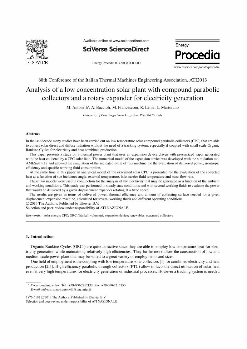
geometry of the lower part of the collector was obtained in the form of a circle involute.
Thus the coordinates of the profile representing the compound parabolic collector were obtained by applying the
well-known relationships [11] for tubular receivers. As an example, fig. 1 reports an elementary scheme of an
untruncated reflector with C = 1.5.
As regard of the useful collectable energy, the analysis was carried out at the steady state. Thus the energy balance
of the investigated collector was calculated as follows, balancing the incoming solar energy captured and the outgoing
energy fluxes (the sum of the useful heat flux and the thermal losses), and neglecting the effect of the thermal capacity
of both the collector and the carrier fluid:
Es,in = Qu + Ql (1)
The incoming energy Es,in into the collector was evaluated as in the following expression, in which F f is a correc-
tion factor that takes into account the non-constant temperature of the fluid within the collector.
Es,in = I · A · ηop · F f (2)
The optical efficiency was evaluated with the commonly used relationship usually reported in literature [1]:
ηop = τcg · τag · ϕN · α · (1 − ξ) (3)
in which the following values were used: τcg = 0.92, τag = 0.94, ϕ = 0.96, N = 0.60, α = 0.91, ξ = 0.02.
4 Author name / Energy Procedia 00 (2013) 000–000
Fig. 1. Elementary scheme of a CPC with C = 1.5
The total heat loss was accounted as the sum of a convective and a radiating loss:
Qu = Ql,con + Ql,rad (4)
The convective and radiating losses were respectively evaluated as:
Ql,con = Ul ·Ac
C(Tr − Ta) Ql,rad = σǫ ·
Ac
C(T 4r − T
4a ) (5)
In literature the lost heat flux is often accounted by an equivalent convective heat transfer coefficient that takes into
account of both the convective and the radiating heat losses and its value is usually the range 10 − 15W/m2K. In this
work however the two losses were separately considered, therefore a much smaller value of Ul was found, since it
accounted only the convective loss that is much reduced due to the presence of the glass envelope.
The evaluation of the convective heat transfer Ul was carried out by calculating the efficiency of the evacuated
tube without the concentrator for several values of Ul (fig.2 reports the results for Ul = 0.3, 0.5 and 0.8 W/m2K as an
example). The results were compared with the values found in literature [4,15–17] and quite a good agreement was
found with Ul = 0.5W/m2K. Although this value might be further reduced due to the presence of the concentrator
that obstacolates the convective phenomena, this was kept unchanged, therefore the results obtained are to be treated
as conservative.
As regard of the receiver temperature Tr, this was calculated as a function of the following quantities: the saturation
temperature of the working fluid Tsat, the temperature rise across the solar field ∆Tv f , the temperature drops between
the receiver and the carrier fluid ∆Tr,v f (pressurized water) and between the carrier fluid and the working fluid ∆Tv f ,w f .
Tr = Tsat +∆Tv f
2+ ∆Tv f + ∆Tv f ,w f (6)
The solar intensity on the collector was evaluated with the model of Liu and Jordan [18] that takes into account the
distribution of direct, diffuse and total solar radiation.
The analysis of the collected energy was carried out by considering several concentration values, tilt angles and
cycle saturation temperatures. The insulation at the latitude of the Central Italy (43o) was used in calculations.
For a given concentration ratio, and hence for a given θac, the maximum collectors tilt angle βmax was calculated in
order to accept the solar rays at the maximum inclination of the sun:
βmax(C) = αmax − (90o + θac) (7)
For a given value of β the minimum angle of sunrays acceptance was calculated as
αmin = 90o − (β + θac) (8)

Author name / Energy Procedia 00 (2013) 000–000 5
Fig. 2. Calculated efficiency of an evacuated tube for several values of Ul
Fig. 3. Basic layout of a solar organic regenerative Rankine plant (a) and cycle on a T − s diagram (b)
2.2. Thermal cycle modeling
As mentioned above, the proposed thermal plant receives the heat captured by the collectors by means of a carrier
fluid (pressurized water), so that the organic vapor is generated in a heat exchanger and not in the collectors. The plant
(fig. 3) is therefore composed by the following apparatus: the solar field, a circulating pump, a vapor generator, an
expansion device, a condenser and a feed pump.
As regard of the condensation phase, in this first analysis the presence of cogeneration was not taken into account
and the use of air condensing units was hypothesized, by imposing a fixed temperature drop between ambient air and
condensing fluid (25oC).
The analysed thermal plant uses an expansion machine derived from a modified Wankel engine. This expansion
device was already described in previously published papers [14] and a prototype was built and tested to verify the
feasibility of this solution as well as to validate the response of the numerical model used also in this paper. The
displacement of this engine was 316 cm3, with a dead volume of 27 cm3 and an eccentricity equal to 12.05mm.
The numerical model used in this work was developed with the simulation tool AMESim v.12.0. As already shown
in previously published papers, this model simulates the behavior of temperature, pressure and other thermodynamic
properties of the working fluid inside the chambers of the expansion device itself. This model was validated by
comparing the numerical with the experimental results obtained at the engine test bench, by taking into account the
delivered power, the inlet mass flow rate and the indicated cycle [14].
6 Author name / Energy Procedia 00 (2013) 000–000
This numerical model calculates the thermodynamic properties of the working fluid by making reference to the
available library of two-phase fluids, among which many organic fluids are present. This way several working fluids
were taken into account to optimize the expansion machine isentropic efficiency for a given inlet thermal power. In
this first analysis only subcritical cycles were considered and a further investigation on supercritical cycles will be
carried out in a future work.
In this analysis the thermal power provided by the solar field was used as input of the simulations together with
the saturation temperature of the working fluid. By means of this numerical model the isentropic efficiency of the
machine and the thermal cycle efficiency were evaluated, as well as the rotating speed that was necessary to handle
the available working fluid mass flow rate mw f .
The useful power delivered was calculated as the power delivered by the expansion device minus the power ab-
sorbed by the pump and the power absorbed by the auxiliaries. Among these last the fans of the condenser assumed
a particular relevance; a survey on the commercially available air condenser showed the specific power absoption per
unit of exchanged thermal power is in the range 5 − 15W/kWth. Conservatively, the highest value was considered.
The efficiency of the thermal plant was calculated in both the cases of regenerative and non regenerative cycle.
3. Performance analysis
In the following lines the results of the analysis of thermal plant and solar field will be presented with a particular
attention to the saturation temperature Tsat of the thermal cycle. In facts, in the previous paragraphs it was pointed
out that Tsat influences the efficiency of both the solar field and the thermal cycle. As a consequence, the saturation
temperature Tsat of the working fluid was considered as the main operating parameter. In this work several satura-
tion temperatures in the range 80 − 130oC were taken into account. Higher values were not considered due to low
concentration of the collectors.
The operating conditions during the month of July were considered as the design point because this is the condition
in which the working fluid mass flow rate is the highest. The captating surface was calculated in order to allow the
engine to rotate at 3000 rpm at the design point.
3.1. Solar field analysis results
The analytical models used allowed the calculation of the monthly and yearly collectable energy per surface unit
of panel. The considered surface was the one of the cover glass, so that from the point of view of the captating surface
these collectors may be treated as flat ones. The calculation of the captured energy was carried out for several values
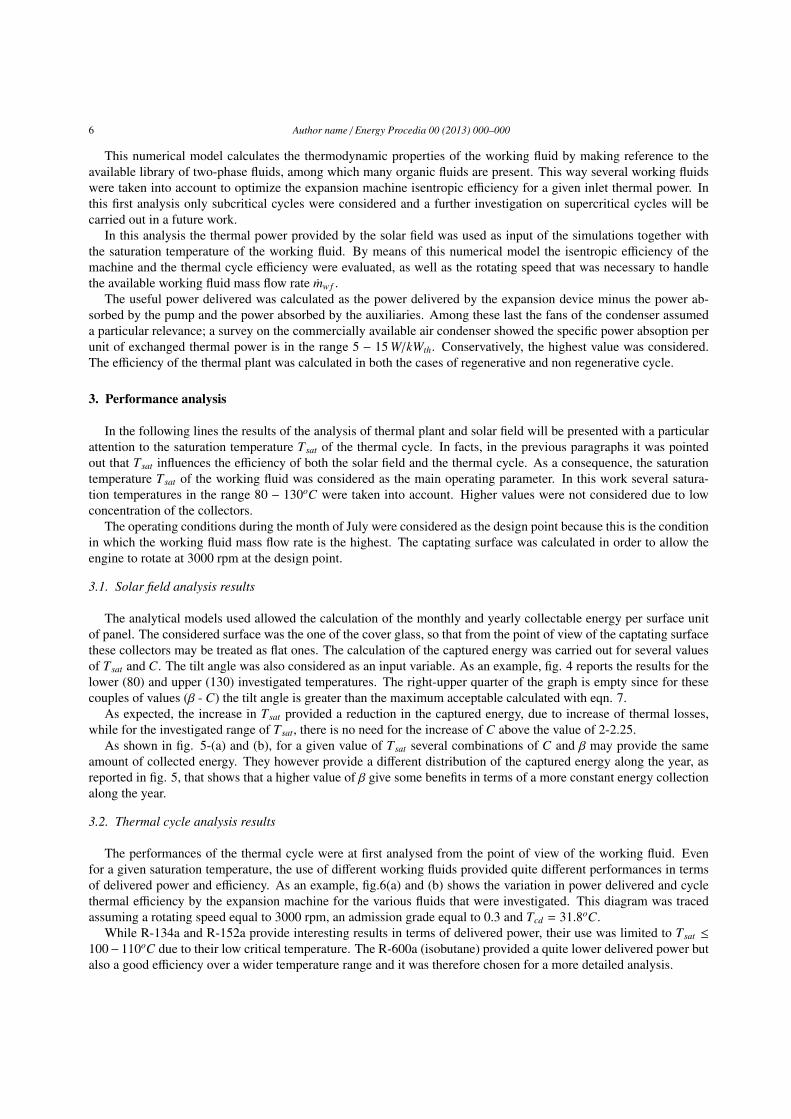
of Tsat and C. The tilt angle was also considered as an input variable. As an example, fig. 4 reports the results for the
lower (80) and upper (130) investigated temperatures. The right-upper quarter of the graph is empty since for these
couples of values (β - C) the tilt angle is greater than the maximum acceptable calculated with eqn. 7.
As expected, the increase in Tsat provided a reduction in the captured energy, due to increase of thermal losses,
while for the investigated range of Tsat, there is no need for the increase of C above the value of 2-2.25.
As shown in fig. 5-(a) and (b), for a given value of Tsat several combinations of C and β may provide the same
amount of collected energy. They however provide a different distribution of the captured energy along the year, as
reported in fig. 5, that shows that a higher value of β give some benefits in terms of a more constant energy collection
along the year.
3.2. Thermal cycle analysis results
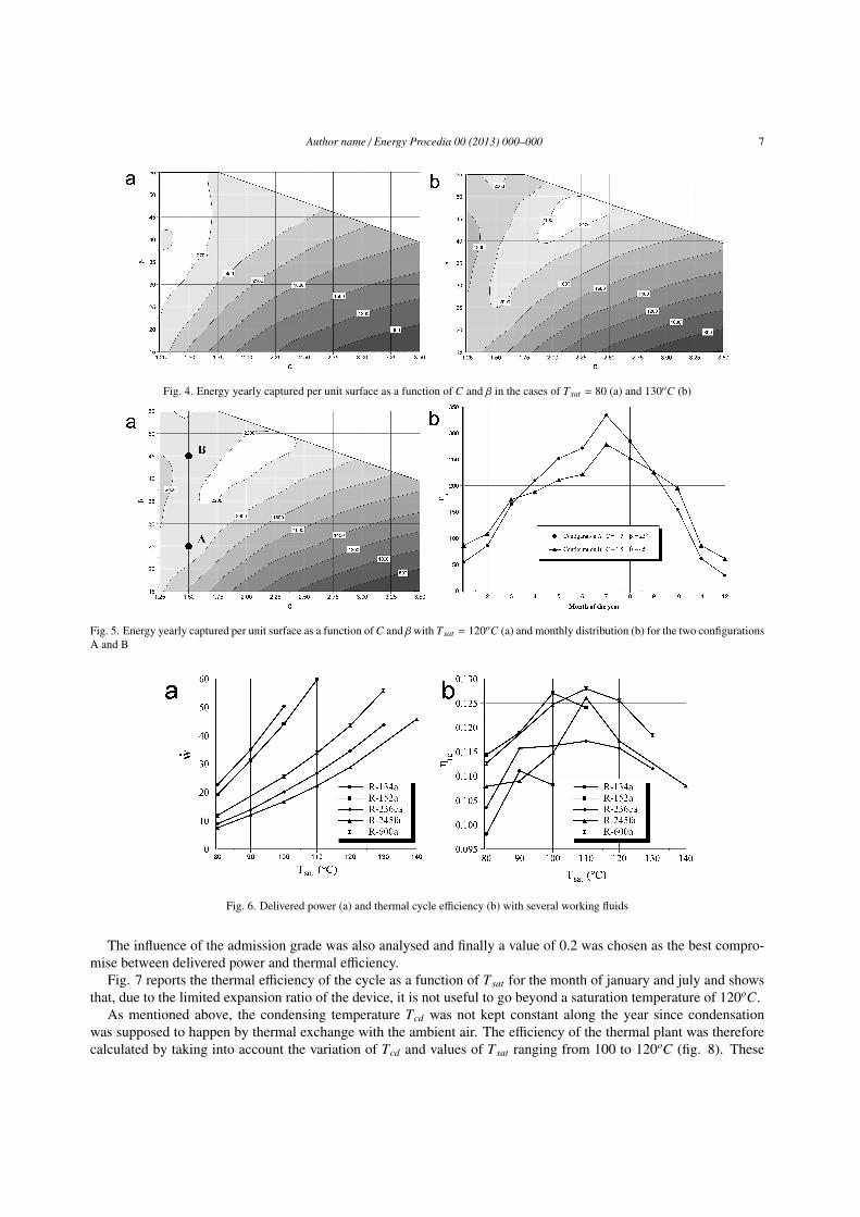
The performances of the thermal cycle were at first analysed from the point of view of the working fluid. Even
for a given saturation temperature, the use of different working fluids provided quite different performances in terms
of delivered power and efficiency. As an example, fig.6(a) and (b) shows the variation in power delivered and cycle
thermal efficiency by the expansion machine for the various fluids that were investigated. This diagram was traced
assuming a rotating speed equal to 3000 rpm, an admission grade equal to 0.3 and Tcd = 31.8oC.
While R-134a and R-152a provide interesting results in terms of delivered power, their use was limited to Tsat ≤
100− 110oC due to their low critical temperature. The R-600a (isobutane) provided a quite lower delivered power but
also a good efficiency over a wider temperature range and it was therefore chosen for a more detailed analysis.
Author name / Energy Procedia 00 (2013) 000–000 7
Fig. 4. Energy yearly captured per unit surface as a function of C and β in the cases of Tsat = 80 (a) and 130oC (b)
Fig. 5. Energy yearly captured per unit surface as a function ofC and βwith Tsat = 120oC (a) and monthly distribution (b) for the two configurations
A and B
Fig. 6. Delivered power (a) and thermal cycle efficiency (b) with several working fluids
The influence of the admission grade was also analysed and finally a value of 0.2 was chosen as the best compro-
mise between delivered power and thermal efficiency.
Fig. 7 reports the thermal efficiency of the cycle as a function of Tsat for the month of january and july and shows
that, due to the limited expansion ratio of the device, it is not useful to go beyond a saturation temperature of 120oC.
As mentioned above, the condensing temperature Tcd was not kept constant along the year since condensation
was supposed to happen by thermal exchange with the ambient air. The efficiency of the thermal plant was therefore
calculated by taking into account the variation of Tcd and values of Tsat ranging from 100 to 120oC (fig. 8). These

8 Author name / Energy Procedia 00 (2013) 000–000
Fig. 7. Thermal cycle efficiency using R-600a as working fluid as a function of Tsat calculated in January and July
Fig. 8. Isentropic efficiency (a) and thermal cycle efficiency (b) calculated along the year using R600-a
results were obtained by taking into account the variation of Qu and mw f . The rotating speed of the expansion device
was supposed to be accomodated to follow the variation of mw f by using an inverter, as hypothesized in other published
papers [19].
Fig 8 also shows that the both the isentropic and the thermal efficiency suffer quite heavy reduction during the
summer months in the case of Tsat = 100oC, while much more reduced variations can be observed at higher values
of Tsat. The isentropic efficiency was comparable and in several cases even higher than a radial turbine of the same
power range [20] or a volumetric expansion device of other type (Scroll as an example) [21–25].
The thermal efficiency of the plant shows the smaller monthly fluctuations in the case of Tsat = 120oC, however
during winter season the efficiency of the plant results to be higher in the case of Tsat = 110oC, due to the higher value
of ηis.
3.3. Plant performance analysis
The analysis of the performance of the whole plant was carried out by combining the previously presented results.
In order to establish which are the optimal values of Tsat, C and β, the yearly generated electricity was calculated. Fig.
9 (a)-(d) shows the results obtained with the aforementioned values of Tsat.
When the plant is operated at constant Tsat along the whole year, the most favourable case is Tsat = 120oC; in this
case the maximum yearly amount of energy is collected when concentration and tilt angle are respectively in the range
C = 1, 75 − 2, 25 and β = 35 − 50o. The lowest values of C require smaller value of β and viceversa. It is then clear
that the decrease in the captating efficiency of the collectors, due to the higher temperature of the receivers, may be
adequately counterbalanced by the increase in the thermal efficiency of the cycle. Moreover, the higher is the thermal

Author name / Energy Procedia 00 (2013) 000–000 9
Fig. 9. Energy yearly generated per unit surface as a function of C and β with Tsat = 100 (a), 110 (b), 120oC (c)and with variable Tsat (d)
efficiency of the cycle, the smaller also is the mechanical power absorbed by the air condensing unit fans. When Tsatis increased from 110 to 120oC, as an example, the consumption of these auxiliaries in the month of July decreases
from 9.1 to 7.0% of the net power.
Conversely, when the plant may be operated at variable Tsat, there is the possibility of both extend the range of
optimal working conditions, also giving the possibility of using smaller values of C with some benefits in terms of
compactness of the concentrators, yearly number of operating hours and sensitivity to cloudy wheather (capability of
capturing the diffuse radiation). In this case, the efficiency of the collectors varies from a minimum in the month of
december (Tsat = 100oC, ηc = 0.35) to a maximum in the month of september (Tsat = 120oC, ηc = 0.51).
The results of the calculations allowed to determine the main features of the plant operating in the optimal con-
ditions; the optimal tilt angle resulted to be β = 40o, the concentration C = 1.75 and the yearly electrical energy
generated was nearly 60 MWh. The total collectors aperture was 750m2 and the ground occupied area was 1670m2.
The maximum overall efficiency of the plant was calculated as 7.27%.
4. Conclusions
The presented analysis pointed out the fundamental role played by the saturation temperature of the working fluid.
This parameter in facts not only influences the efficiency of the thermal cycle but also the captating efficiency of
the solar plant, the isentropic efficiency of the expansion device and, as a consequence, the power absorbed by the
auxiliaries.
The isentropic and the thermal cycle efficiencies were calculated by means of the numerical model developed with
the simulation tools AMESim, that allowed the calculation of the indicated cycle of the expansion device, that was
assumed to be a volumetric one, derived from a Wankel engine, as proposed in previously published papers. This
device proved to be able to maintain a reltively high isentropic efficiency over a wide range of working fluids and
operating conditions, due to the possibility of choosing the proper admission grade for every application.
This analysis allowed to determine the optimal conditions from the point of view of the energy produced per unit of
collector aperture area, in terms of working fluid saturation temperature, tilt angle and concentration. This calculation
was carried out by assuming that no tilt adjustment has to be done along the year.
10 Author name / Energy Procedia 00 (2013) 000–000
The analysis pointed out that temperatures above 110-120oC don’t provide any noticeable advantage, especially if
the expansion takes place in a single stage device and this mainly due to the decrease of both the isentropic efficiency
of the expansion device and the captating efficiency of the solar field. The use of these low saturation temperatures
also allows the use of a limited receivers temperature and therefore there is no need for the increase of concentration
above 1.75-2.25.
The energy produced may be lower than a well designed photovoltaic plant, however it must be underlined that
much work has to be done to analysis the full potentialities of this kind of systems, among which the use of non-
symmetrical concentrators and multiple stage expansion in conjunction with supercritical cycles may be only some
examples.
References
[1] Duffie J. A., Beckman W. A. Solar thermal engineering. Madison: John Wiley and Sons; 1980.
[2] Gang Pei, Jing Li, Jie Ji. Analysis of low temperature solar thermal electric generation using regenerative Organic Rankine Cycle (2010)
Applied Thermal Engineering, Volume 30, Issues 89, pp. 998-1004.
[3] Jing L., Gang P., JieJ. Optimization of low temperature solar thermal electric generation with Organic Rankine Cycle in different areas (2010)
Applied Energy, Volume 87, Issue 11, pp. 3355-3365.
[4] Zhang, W., Ma, X., Omer, S.A., Riffat, S.B. Optimum selection of solar collectors for a solar-driven ejector air conditioning system by
experimental and simulation study (2012) Energy Conversion and Management, 63, pp. 106-111.
[5] Winston, R. Principles of solar concentrators of a novel design (1974) Solar Energy, 16 (2), pp. 89-95.
[6] Winston, R., Hinterberger, H. Principles of cylindrical concentrators for solar energy (1975) Solar Energy, 17 (4), pp. 255-258.Macmillan;
1979.
[7] Rabl, A. Comparison of solar concentrators (1976) Solar Energy, 18 (2), pp. 93-111
[8] Rabl, A. Solar concentrators with maximal concentration for cylindrical absorbers (1976) Applied Optics, 15 (7), pp. 1871-1873.
[9] Buttinger, F., Beikircher, T., Proll, M., Scholkopf, W. Development of a new flat stationary evacuated CPC-collector for process heat applica-
tions (2010) Solar Energy, 84 (7), pp. 1166-1174.
[10] Mills, D.R., Bassett, I.M., Derrick, G.H. Relative cost-effectiveness of CPC reflector designs suitable for evacuated absorber tube solar collec-
tors (1986) Solar Energy, 36 (3), pp. 199-206.
[11] Vargas J.V.C., Ordonez J.C., Dilay E., Parise J.A.R. Modeling, simulation and optimization of a solar collector driven water heating and
absorption cooling plant (2009) Solar Energy, Volume 83, Issue 8, pp. 1232-1244.
[12] Badr O, Naik S, O’Callaghan PW, Probert S D. Rotary Wankel engines as expansion devices in steam Rankine-cycle engines. Applied Energy
Volume 39, Issue 1 (1991) 59-76.
[13] Badr O. Naik S. O’Callaghan P W, Probert S D. Wankel engines as steam expanders: Design considerations. Applied Energy Volume 40, Issue
2 (1991) 157-170.
[14] Antonelli M., Martorano L. A study on the rotary steam engine for distributed generation in small size power plants (2012) Applied Energy,
Volume 97, pp. 642-647.
[15] Zhang, X.R., Yamaguchi, H. An experimental study on evacuated tube solar collector using supercritical CO2 (2008) Applied Thermal Engi-
neering, 28 (10), pp. 1225-1233
[16] Ma, L., Lu, Z., Zhang, J., Liang, R. Thermal performance analysis of the glass evacuated tube solar collector with U-tube (2010) Building and
Environment, 45 (9), pp. 1959-1967
[17] Atkins, M.J., Walmsley, M.R.W., Morrison, A.S. Integration of solar thermal for improved energy efficiency in low-temperature-pinch indus-
trial processes (2010) Energy, 35 (5), pp. 1867-1873.
[18] [8] Liu BYH, Jordan R C. The inter-relationship and characteristic distribution of direct, diffuse and total solar radiation. Solar Energy
1960;4(3):119.
[19] Badami M., Mura M. Preliminary design and controlling strategies of a small-scale wood waste Rankine Cycle (RC) with a reciprocating steam
engine (SE) (2009) Energy, Volume 34, Issue 9, pp. 1315-1324.
[20] Fiaschi D., Manfrida G., Maraschiello F. Thermo-fluid dynamics preliminary design of turbo-expanders for ORC cycles (2012) Applied Energy,
Volume 97, pp. 601-608.
[21] Lemort V., Quoilin S., Cuevas C., Lebrun J. Testing and modeling a scroll expander integrated into an Organic Rankine Cycle (2009) Applied
Thermal Engineering, Volume 29, Issues 1415 pp. 3094-3102.
[22] Declaye S., Quoilin S., Guillaume L., Lemort V., Experimental study on an open-drive scroll expander integrated into an ORC (Organic
Rankine Cycle) system with R245fa as working fluid (2013) Energy, Volume 55, pp. 173-183.
[23] Quoilin S., Lemort V., Lebrun J., Experimental study and modeling of an Organic Rankine Cycle using scroll expander (2010) Applied Energy,
Volume 87, Issue 4, pp. 1260-1268.
[24] Guangbin L., Yuanyang Z., Liansheng L., Pengcheng S. Simulation and experiment research on wide ranging working process of scroll
expander driven by compressed air (2010) Applied Thermal Engineering, Volume 30, Issues 1415, pp. 2073-2079.
[25] Clemente S., Micheli D., Reini M., Taccani R. Energy efficiency analysis of Organic Rankine Cycles with scroll expanders for cogenerative
applications (2012) Applied Energy, Volume 97, pp. 792-801.