DEVELOPING AN ELECTRONIC TRACKING SYSTEM FOR SOLAR COLLECTORS
Parabolic-trough solar collectors and their applications
27
Parabolic-trough solar collectors and their applications A. Ferna ´ ndez-Garcı ´a a, *, E. Zarza a , L. Valenzuela a , M. Pe ´ rez b a CIEMAT-Plataforma Solar de Almerı´a, Ctra. Sene ´s, km. 4, Tabernas (Almerı´a) 04200, Spain b Departamento de Fı´sica Aplicada, Universidad de Almerı´a, Almerı´a 04120, Spain Contents 1. Introduction .................................................................................................... 1696 2. Parabolic-trough collectors ........................................................................................ 1696 2.1. The beginning ............................................................................................. 1696 2.2. First commercial collectors................................................................................... 1697 2.3. Collectors for CSP plants..................................................................................... 1699 2.3.1. Luz collectors ...................................................................................... 1699 2.3.2. EuroTrough collector ................................................................................ 1700 2.3.3. Other current collectors ............................................................................. 1701 Renewable and Sustainable Energy Reviews 14 (2010) 1695–1721 ARTICLE INFO Article history: Received 16 December 2009 Accepted 5 March 2010 Keywords: Solar energy Solar collector Concentrated Solar Power plant Industrial process heat Heat water production Solar cooling ABSTRACT This paper presents an overview of the parabolic-trough collectors that have been built and marketed during the past century, as well as the prototypes currently under development. It also presents a survey of systems which could incorporate this type of concentrating solar system to supply thermal energy up to 400 8C, especially steam power cycles for electricity generation, including examples of each application. ß 2010 Elsevier Ltd. All rights reserved. Abbreviations: AC, Air-conditioning; AIST, National Institute of Advanced Industrial Science and Technology (Japan); APS, Arizona Public Service (United States); ARDISS, Advanced Receiver for Direct Solar Steam; ATS, Advanced Trough System; BMU, Bundesministeriums fu ¨r Umwelt, Naturschutz und Reaktorsicherheit (Germany); BOP, Balance of Plant; CC, Combined cycle; CFE, Comisio ´n Federal de Electricidad (Mexico); CIEMAT, Centro de Investigaciones Energe ´ticas Medioambientales y Tecnolo ´gicas (Spain); COP, Coefficient of Performance; CPC, Compound parabolic concentrator; CSIRO, Commonwealth Scientific and Industrial Research Organization (Australia); CSP, Concentrated Solar Power; DCS, Distributed Collectors System; DE, Double-effect; DHW, Domestic hot water; DISS, Direct Solar Steam; DLR, Deutsches Zentrum fu ¨r Luft und Raumfahrt (Germany); DNI, Direct Normal Irradiance; DSG, Direct Steam Generation; DOE, Department Of Energy (United States); DFVLR, Deutsche Forschungs und Versuchsanstalt fu ¨r Luft und Raumfahrt (Germany); EEA, Egyptian Electricity Authority (Egypt); EPC, Engineering procurement and Construction; FB, Flash boiler; FEMP, Federal Energy Management Program (United States); FPC, Flat plate collector; GEF, Global Environmental Facility; GUDE, Grundlegende Untersuchungen zur Solares Direktverdampfung von Wasser nach dem Einspritzprinzip; HCE, Heat Collector Element; HE, Heat exchanger; HTF, Heat transfer fluid; HRSG, Heat Recovery Steam Generator; IEA, International Energy Agency; INDITEP, Integration of Direct Steam Generation Technology for Electricity Production; IDAE, Instituto para la Diversificacio ´n y el Ahorro Energe ´tico (Spain); IIE, Instituto de Investigaciones Ele ´ctricas (Mexico); IPDC, Iranian Power Development Company (Iran); IPH, Industrial process heat; IPP, Independent Power Project; ISCCS, Integrated Solar Combined-Cycle System; IST, Industrial Solar Technology Corporation (United States); KfW, Kreditanstals fur Wiederaufbau (Germany); LPC, Linear Parabolic Concentrating Collector; M.A.N., Maschinenfabrik Augsburg-Nu ¨rnberg (Germany); MED, Multi-effect Destilation; MOEE, Ministry of Electricity and Energy (Egypt); MSF, Multi-stage Flash; NEAL, New Energy Algeria (Algeria); NEP, New Energy Partners (Australia); NREA, New and Renewable Energy Authority (Egypt); O&M, Operation and maintenance; ONE, Office National de l’Electricite ´ (Morocco); ORC, Organic Rankine Cycle; PF, Photo-Fenton; PG&E, Pacific Gas and Electric (United States); PSA, Plataforma Solar de Almerı´a (Spain); PTC, Parabolic-trough collector; PURPA, Public Utility Regulatory Policies Act (United States); RMT, Roof Mount Parabolic Trough; RO, Reverse Osmosis; RPS, Renewable Portfolio Standard; RR, Rankine cycle with reheat; RREC, Rajasthan Renewable Energy Corporation (India); RfP, Request for Proposals; RRg, Rankine cycle with regeneration; RS, Rankine cycle with superheat; SACE, Solar Air Conditioning in Europe; SCE, Southern California Edison (United States); SE, Single-effect; SEGS, Solar Electric Generating Systems (United States); SERI, Solar Energy Research Institute (United States); SHAP, Solar Heat and Power (Italy); SHC, Solar Heating and Cooling; SIJ, Solar Institut Ju ¨lich (Germany); SO, Standard Offer; SPP1, Solar Power Plant One (United States); SSPS, Small Solar Power System Project; STEM, Solar Thermal Electricity for Mediterranean Countries; TC, Tubular Collector; TMR, Tarifa Media de Referencia; TOSCA, Trough with an Optimized SeCondary in Air; UAE, United Arab Emirates; UNAM, Universidad Nacional Auto ´noma de Me ´xico (Mexico); UVAC, Universal Vacuum Collector; VC, V-Trough Collector; WGA, Western Governors’ Association (United States). * Corresponding author. Tel.: +34 950 387950; fax: +34 950 365015. E-mail address: [email protected] (A. Ferna ´ ndez-Garcı ´a). Contents lists available at ScienceDirect Renewable and Sustainable Energy Reviews journal homepage: www.elsevier.com/locate/rser 1364-0321/$ – see front matter ß 2010 Elsevier Ltd. All rights reserved. doi:10.1016/j.rser.2010.03.012
Transcript of Parabolic-trough solar collectors and their applications
Renewable and Sustainable Energy Reviews 14 (2010) 1695–1721
Parabolic-trough solar collectors and their applications
A. Fernandez-Garcıa a,*, E. Zarza a, L. Valenzuela a, M. Perez b
a CIEMAT-Plataforma Solar de Almerıa, Ctra. Senes, km. 4, Tabernas (Almerıa) 04200, Spainb Departamento de Fısica Aplicada, Universidad de Almerıa, Almerıa 04120, Spain
Contents
1. Introduction . . . . . . . . . . . . . . . . . . . . . . . . . . . . . . . . . . . . . . . . . . . . . . . . . . . . . . . . . . . . . . . . . . . . . . . . . . . . . . . . . . . . . . . . . . . . . . . . . . . . 1696
2. Parabolic-trough collectors . . . . . . . . . . . . . . . . . . . . . . . . . . . . . . . . . . . . . . . . . . . . . . . . . . . . . . . . . . . . . . . . . . . . . . . . . . . . . . . . . . . . . . . . 1696
2.1. The beginning . . . . . . . . . . . . . . . . . . . . . . . . . . . . . . . . . . . . . . . . . . . . . . . . . . . . . . . . . . . . . . . . . . . . . . . . . . . . . . . . . . . . . . . . . . . . . 1696
2.2. First commercial collectors. . . . . . . . . . . . . . . . . . . . . . . . . . . . . . . . . . . . . . . . . . . . . . . . . . . . . . . . . . . . . . . . . . . . . . . . . . . . . . . . . . . 1697
2.3. Collectors for CSP plants. . . . . . . . . . . . . . . . . . . . . . . . . . . . . . . . . . . . . . . . . . . . . . . . . . . . . . . . . . . . . . . . . . . . . . . . . . . . . . . . . . . . . 1699
2.3.1. Luz collectors . . . . . . . . . . . . . . . . . . . . . . . . . . . . . . . . . . . . . . . . . . . . . . . . . . . . . . . . . . . . . . . . . . . . . . . . . . . . . . . . . . . . . . 1699
2.3.2. EuroTrough collector . . . . . . . . . . . . . . . . . . . . . . . . . . . . . . . . . . . . . . . . . . . . . . . . . . . . . . . . . . . . . . . . . . . . . . . . . . . . . . . . 1700
2.3.3. Other current collectors . . . . . . . . . . . . . . . . . . . . . . . . . . . . . . . . . . . . . . . . . . . . . . . . . . . . . . . . . . . . . . . . . . . . . . . . . . . . . 1701
A R T I C L E I N F O
Article history:
Received 16 December 2009
Accepted 5 March 2010
Keywords:
Solar energy
Solar collector
Concentrated Solar Power plant
Industrial process heat
Heat water production
Solar cooling
A B S T R A C T
This paper presents an overview of the parabolic-trough collectors that have been built and marketed
during the past century, as well as the prototypes currently under development. It also presents a survey
of systems which could incorporate this type of concentrating solar system to supply thermal energy up
to 400 8C, especially steam power cycles for electricity generation, including examples of each
application.
� 2010 Elsevier Ltd. All rights reserved.
Abbreviations: AC, Air-conditioning; AIST, National Institute of Advanced Industrial Science and Technology (Japan); APS, Arizona Public Service (United States); ARDISS,
Advanced Receiver for Direct Solar Steam; ATS, Advanced Trough System; BMU, Bundesministeriums fur Umwelt, Naturschutz und Reaktorsicherheit (Germany); BOP, Balance of
Plant; CC, Combined cycle; CFE, Comision Federal de Electricidad (Mexico); CIEMAT, Centro de Investigaciones Energeticas Medioambientales y Tecnologicas (Spain); COP,
Coefficient of Performance; CPC, Compound parabolic concentrator; CSIRO, Commonwealth Scientific and Industrial Research Organization (Australia); CSP, Concentrated
Solar Power; DCS, Distributed Collectors System; DE, Double-effect; DHW, Domestic hot water; DISS, Direct Solar Steam; DLR, Deutsches Zentrum fur Luft und Raumfahrt
(Germany); DNI, Direct Normal Irradiance; DSG, Direct Steam Generation; DOE, Department Of Energy (United States); DFVLR, Deutsche Forschungs und Versuchsanstalt fur
Luft und Raumfahrt (Germany); EEA, Egyptian Electricity Authority (Egypt); EPC, Engineering procurement and Construction; FB, Flash boiler; FEMP, Federal Energy
Management Program (United States); FPC, Flat plate collector; GEF, Global Environmental Facility; GUDE, Grundlegende Untersuchungen zur Solares Direktverdampfung von
Wasser nach dem Einspritzprinzip; HCE, Heat Collector Element; HE, Heat exchanger; HTF, Heat transfer fluid; HRSG, Heat Recovery Steam Generator; IEA, International Energy
Agency; INDITEP, Integration of Direct Steam Generation Technology for Electricity Production; IDAE, Instituto para la Diversificacion y el Ahorro Energetico (Spain); IIE, Instituto
de Investigaciones Electricas (Mexico); IPDC, Iranian Power Development Company (Iran); IPH, Industrial process heat; IPP, Independent Power Project; ISCCS, Integrated Solar
Combined-Cycle System; IST, Industrial Solar Technology Corporation (United States); KfW, Kreditanstals fur Wiederaufbau (Germany); LPC, Linear Parabolic Concentrating
Collector; M.A.N., Maschinenfabrik Augsburg-Nurnberg (Germany); MED, Multi-effect Destilation; MOEE, Ministry of Electricity and Energy (Egypt); MSF, Multi-stage Flash;
NEAL, New Energy Algeria (Algeria); NEP, New Energy Partners (Australia); NREA, New and Renewable Energy Authority (Egypt); O&M, Operation and maintenance; ONE,
Office National de l’Electricite (Morocco); ORC, Organic Rankine Cycle; PF, Photo-Fenton; PG&E, Pacific Gas and Electric (United States); PSA, Plataforma Solar de Almerıa (Spain);
PTC, Parabolic-trough collector; PURPA, Public Utility Regulatory Policies Act (United States); RMT, Roof Mount Parabolic Trough; RO, Reverse Osmosis; RPS, Renewable
Portfolio Standard; RR, Rankine cycle with reheat; RREC, Rajasthan Renewable Energy Corporation (India); RfP, Request for Proposals; RRg, Rankine cycle with regeneration;
RS, Rankine cycle with superheat; SACE, Solar Air Conditioning in Europe; SCE, Southern California Edison (United States); SE, Single-effect; SEGS, Solar Electric Generating
Systems (United States); SERI, Solar Energy Research Institute (United States); SHAP, Solar Heat and Power (Italy); SHC, Solar Heating and Cooling; SIJ, Solar Institut Julich
Contents lists available at ScienceDirect
Renewable and Sustainable Energy Reviews
journa l homepage: www.e lsev ier .com/ locate / rser
(Germany); SO, Standard Offer; SPP1, Solar Power Plant One (United States); SSPS, Small Solar Power System Project; STEM, Solar Thermal Electricity for Mediterranean
Countries; TC, Tubular Collector; TMR, Tarifa Media de Referencia; TOSCA, Trough with an Optimized SeCondary in Air; UAE, United Arab Emirates; UNAM, Universidad Nacional
Autonoma de Mexico (Mexico); UVAC, Universal Vacuum Collector; VC, V-Trough Collector; WGA, Western Governors’ Association (United States).
* Corresponding author. Tel.: +34 950 387950; fax: +34 950 365015.
E-mail address: [email protected] (A. Fernandez-Garcıa).
1364-0321/$ – see front matter � 2010 Elsevier Ltd. All rights reserved.
doi:10.1016/j.rser.2010.03.012
A. Fernandez-Garcıa et al. / Renewable and Sustainable Energy Reviews 14 (2010) 1695–17211696
2.4. Collectors for applications at temperatures up to 250 8C . . . . . . . . . . . . . . . . . . . . . . . . . . . . . . . . . . . . . . . . . . . . . . . . . . . . . . . . . . . 1701
2.4.1. Commercial collectors . . . . . . . . . . . . . . . . . . . . . . . . . . . . . . . . . . . . . . . . . . . . . . . . . . . . . . . . . . . . . . . . . . . . . . . . . . . . . . . 1702
2.4.2. Prototypes . . . . . . . . . . . . . . . . . . . . . . . . . . . . . . . . . . . . . . . . . . . . . . . . . . . . . . . . . . . . . . . . . . . . . . . . . . . . . . . . . . . . . . . . 1702
3. Applications . . . . . . . . . . . . . . . . . . . . . . . . . . . . . . . . . . . . . . . . . . . . . . . . . . . . . . . . . . . . . . . . . . . . . . . . . . . . . . . . . . . . . . . . . . . . . . . . . . . . 1703
3.1. CSP plants . . . . . . . . . . . . . . . . . . . . . . . . . . . . . . . . . . . . . . . . . . . . . . . . . . . . . . . . . . . . . . . . . . . . . . . . . . . . . . . . . . . . . . . . . . . . . . . . 1703
3.1.1. SEGS plants . . . . . . . . . . . . . . . . . . . . . . . . . . . . . . . . . . . . . . . . . . . . . . . . . . . . . . . . . . . . . . . . . . . . . . . . . . . . . . . . . . . . . . . 1703
3.1.2. SSPS project . . . . . . . . . . . . . . . . . . . . . . . . . . . . . . . . . . . . . . . . . . . . . . . . . . . . . . . . . . . . . . . . . . . . . . . . . . . . . . . . . . . . . . . 1704
3.1.3. Current state of CSP in the United States . . . . . . . . . . . . . . . . . . . . . . . . . . . . . . . . . . . . . . . . . . . . . . . . . . . . . . . . . . . . . . . . 1705
3.1.4. Current state of CSP in Europe . . . . . . . . . . . . . . . . . . . . . . . . . . . . . . . . . . . . . . . . . . . . . . . . . . . . . . . . . . . . . . . . . . . . . . . . 1705
3.1.5. Current state of CSP in the North of Africa . . . . . . . . . . . . . . . . . . . . . . . . . . . . . . . . . . . . . . . . . . . . . . . . . . . . . . . . . . . . . . 1708
3.1.6. Current state of CSP in the Middle East . . . . . . . . . . . . . . . . . . . . . . . . . . . . . . . . . . . . . . . . . . . . . . . . . . . . . . . . . . . . . . . . . 1709
3.1.7. Current state of CSP in other countries . . . . . . . . . . . . . . . . . . . . . . . . . . . . . . . . . . . . . . . . . . . . . . . . . . . . . . . . . . . . . . . . . 1709
3.1.8. DSG technology . . . . . . . . . . . . . . . . . . . . . . . . . . . . . . . . . . . . . . . . . . . . . . . . . . . . . . . . . . . . . . . . . . . . . . . . . . . . . . . . . . . . 1710
3.2. Industrial process heat (IHP) . . . . . . . . . . . . . . . . . . . . . . . . . . . . . . . . . . . . . . . . . . . . . . . . . . . . . . . . . . . . . . . . . . . . . . . . . . . . . . . . . 1712
3.3. Domestic hot water and space heating . . . . . . . . . . . . . . . . . . . . . . . . . . . . . . . . . . . . . . . . . . . . . . . . . . . . . . . . . . . . . . . . . . . . . . . . . 1712
3.4. Air-conditioning and refrigeration . . . . . . . . . . . . . . . . . . . . . . . . . . . . . . . . . . . . . . . . . . . . . . . . . . . . . . . . . . . . . . . . . . . . . . . . . . . . . 1713
3.5. Pumping irrigation water . . . . . . . . . . . . . . . . . . . . . . . . . . . . . . . . . . . . . . . . . . . . . . . . . . . . . . . . . . . . . . . . . . . . . . . . . . . . . . . . . . . . 1714
3.6. Desalination . . . . . . . . . . . . . . . . . . . . . . . . . . . . . . . . . . . . . . . . . . . . . . . . . . . . . . . . . . . . . . . . . . . . . . . . . . . . . . . . . . . . . . . . . . . . . . 1717
3.7. Solar chemistry . . . . . . . . . . . . . . . . . . . . . . . . . . . . . . . . . . . . . . . . . . . . . . . . . . . . . . . . . . . . . . . . . . . . . . . . . . . . . . . . . . . . . . . . . . . . 1717
References . . . . . . . . . . . . . . . . . . . . . . . . . . . . . . . . . . . . . . . . . . . . . . . . . . . . . . . . . . . . . . . . . . . . . . . . . . . . . . . . . . . . . . . . . . . . . . . . . . . . . 1717
1. Introduction
Solar radiation is a high-temperature, high-exergy energysource at its origin, the Sun, where its irradiance is about 63 MW/m2. However, Sun–Earth geometry dramatically decreases thesolar energy flow down to around 1 kW/m2 on the Earth’s surface[1]. Nevertheless, under high solar flux, this disadvantage can beovercome by using concentrating solar systems which transformsolar energy into another type of energy (usually thermal).
Solar radiation is converted into thermal energy in the focus ofsolar thermal concentrating systems. These systems are classifiedby their focus geometry as either point-focus concentrators(central receiver systems and parabolic dishes) or line-focusconcentrators (parabolic-trough collectors (PTCs) and linearFresnel collectors).
PTCs focus direct solar radiation onto a focal line on thecollector axis. A receiver tube with a fluid flowing inside thatabsorbs concentrated solar energy from the tube walls and raisesits enthalpy is installed in this focal line. The collector is providedwith one-axis solar tracking to ensure that the solar beam fallsparallel to its axis. PTCs can only use direct solar radiation, calledbeam radiation or Direct Normal Irradiance (DNI), i.e., the fractionof solar radiation which is not deviated by clouds, fumes or dust inthe atmosphere and that reaches the Earth’s surface as a parallelbeam.
PTC applications can be divided into two main groups. The firstand most important is Concentrated Solar Power (CSP) plants.There are currently several commercial collectors for suchapplications that have been successfully tested under realoperating conditions. Typical aperture widths are about 6 m, totallengths are from 100 to 150 m and geometrical concentratingratios are between 20 and 30. Temperatures are from 300 to 400 8C.CSP plants with PTCs are connected to steam power cycles bothdirectly and indirectly. Although the most famous example of CSPplants is the SEGS plants in the United States, a number of projectsare currently under development or construction worldwide.
The other group of applications requires temperatures between100 and 250 8C. These applications are mainly industrial processheat (IPH), low-temperature heat demand with high consumptionrates (domestic hot water, DHW, space heating and swimming-pool heating) and heat-driven refrigeration and cooling. Typicalaperture widths are between 1 and 3 m, total lengths vary between2 and 10 m and geometrical concentrating ratios are between 15and 20. Most of the facilities are located in the United States,
although some have recently been built in other countries. Thereare also some projects and facilities for other applications such aspumping irrigation water, desalination and detoxification.
2. Parabolic-trough collectors
This section presents a review of PTC models throughout thehistory of the technology, briefly mentioning their main features,applications, manufactures or public institutions involved in theirdevelopment, and commercial availability.
2.1. The beginning
The first practical experience with PTCs goes back to 1870,when a successful engineer, John Ericsson, a Swedish immigrant tothe United States, designed and built a 3.25-m2-aperture collectorwhich drove a small 373-W engine. Steam was produced directlyinside the solar collector (today called Direct Steam Generation orDSG). From 1872 to 1875, he built seven similar systems, but withair as the working fluid [2]. In 1883, Ericsson constructed a large‘‘sun motor’’ which was exhibited in New York. It consisted of a3.35-m-long, 4.88-m-wide PTC, focusing solar radiation on a15.88-cm-diameter boiler tube. The concentrator consisted ofstraight wooden staves, supported by parabolic curved iron ribsattached to the sides of the trough. The reflecting plates, made offlat window glass silvered on the underside, were fastened onthese staves. The entire device tracked the sun manually. Theengine’s average speed during summer trials was 120 rpm and theabsolute piston working pressure was 0.24 MPa [3]. In 1886, heexperimented with a 1.86-kW solar engine [2]. Ericsson declined togive technical details about the boilers for protective reasons and,unfortunately, he died in 1889 before finishing a commercialversion of his ‘‘sun motor’’, and his project was never continued.
The next reference is dated 1907, when Wilhelm Maier of Aalen(Germany) and Adolf Remshardt of Stuttgart (Germany), patenteda PTC with DSG [4].
From 1906 to 1911, an American engineer, Frank Shuman, builtand tested a number of solar engines. He used different types ofnon-concentrating and low-concentrating solar collectors (anabsorber with flat reflector wings). Some of them were used forpumping irrigation water in Tacony, Pennsylvania (United States).In 1912, with the knowledge and experience gained in thesepreliminary tests, Shuman designed and installed a large irrigationpumping plant in Meadi, a small agricultural village south of El
A. Fernandez-Garcıa et al. / Renewable and Sustainable Energy Reviews 14 (2010) 1695–1721 1697
Cairo, near the Nile River (Egypt). Shuman worked with CharlesVernon Boys, an English consultant, who suggested substantialchanges in the construction of the collectors. Glass-covered boilertubes were placed along the focal axis of a PTC. These solarcollectors produced 0.1-MPa saturated steam directly inside theabsorber tube. Each of the five north–south-facing PTC rows was62.17 m long and 4.1 m wide, providing a total collecting surface ofabout 1250 m2 and occupying nearly 4047 m2 of land. Theabsorber tubes were 8.9 cm in diameter and had a concentrationratio of 4.6 which resulted in an overall peak absorber efficiency of40.7% [2,5].
Shuman and Boys’s reflector consisted of a number of strips offlat mirror, leaving narrow spaces between the adjacent edges sothe wind could blow off dust on the mirrors through them. Theabsorber tubes and mirror system were supported on a lightweightcrescent-shaped lattice, arranged at intervals and parallel to oneanother, and were tilted by means of a rack and pinion gear. Toautomatically align the absorber with the sun, a thermopile orthermostat was placed in the centre of the parabola (under theabsorber tube). As long as it remained in the shadow of the tube,that is, the collector was correctly focused, the tracking motor didnot turn. But as soon as the Sun’s rays impinged upon thethermopile or the thermostat, either the thermopile generated acurrent or the thermostat a temperature increase, which activatedthe motor, turning the collector until the thermopile or thermostatwas again shaded, and the motion stopped [6].
The Meadi plant was originally rated at 75 kW mechanicalenergy and, while reports on real output vary from just over 14 kWto a maximum of 54 kW by Pytlinski [2], it was suggested that witha good steam engine of the sort available at the time, the plantcould have delivered some 41 kW [7]. This plant required aninvestment of $250,000 [5]. After the plant was started upsuccessfully in 1913, Schuman was asked to build a number ofother plants around the world, but in view of the outbreak of WorldWar I and the low price of fuel in the international energy market,he aborted all his plans and the plant was abandoned in 1915 [7]. Inspite of everything, the system was patented in 1917 [6].
In 1936, C.G. Abbot converted solar energy into mechanicalpower by using a PTC and a 0.37-kW steam engine. The authorclaimed an overall system efficiency of 15.5%. A single-tube flash-boiler encased in a double-walled evacuated glass sleeve to reduceheat loss was installed along the focal axis. The system was designedto raise full steam pressure within five minutes of exposure to the
Table 1Main characteristics of the first commercial PTCs.
Company or institution Acurex Corp. S
Model 3001 3011 T-700
Country USA USA USA
Max. operating temp. (8C) 320 320 350
Aperture area (m2) 72.29 78.09 77.96
Aperture width (m) 1.83 2.13 2.13
Length (m) 39.5 36.66 36.6
Focal length (m) 0.457 0.533 0.559
Absorber tube diameter (mm) 31.8 31.8 41.3a(1), 3
Cover tube diameter (mm) 50.8 54.0 63.5(1), 52
Reflector glass thickness (mm) 0.8 0.8 b
Rim angle (8) 90.0 90.0 90.0
Acceptance angle (8) 1.99 1.71 2.22(1), 1.7
Geometric concentration ratio 18.32 21.32 16.42(1), 2
Peak optical efficiency 0.708c 0.827c 0.736(1), 0
Reflectance 0.94 0.94 0.84
Transmittance 0.91 0.95 0.95
Absorptance 0.94 0.94 0.94
Emittance (at temp. (8C)) 0.20 (300) 0.20 (300) 0.20 (300
References [10–13] [10,14] [15]
a Two different absorber tube outer diameters were tested: (1) 41.3 mm and (2) 31.b Unavailable datum.c Authors remark no founded reasons for this large dissimilarity.
Sun’s rays, producing saturated steam at 374 8C [2]. In 1938 he used asimilar boiler in Florida to power a 0.15 kW steam engine. As quotedby Spencer, ‘‘Abbot suggested that a system using this boiler toproduce steam at 225 8C should obtain a theoretical overallefficiency of 15.5% and a real efficiency of 11.7%’’ [7].
2.2. First commercial collectors
The interest in solar concentrating technology was negligiblefor almost 60 years. However, in reaction to the oil crisis of theseventies, international attention was drawn to alternative energysources to supplement fossil fuels, and the development of anumber of parabolic-trough systems was sponsored. Unfortu-nately, the range of products described in this section is no longeron the market.
The U.S. Government’s Sandia National Laboratories andHoneywell International Inc. designed the first two collectors inthe United States in the mid-70s. Both collectors were quite similarin concept and were prepared to work at temperatures below250 8C. A third American company, Westinghouse, becameinvolved in development of the incipient technology at itsProduction Technology Centre and adapted Sandia’s design. InJuly 1975, three troughs were built and tested at Sandia. These3.66-m-long collectors had a 2.13-m-wide aperture, and a 908 rimangle, and a 4-cm-diameter glass-encased black-chrome-coatedcarbon-steel absorber, with a 1-cm evacuated annulus. One ofthem employed an impregnated plywood shell, and another wasmade of fibreglass. Anodized aluminium by Alzak and back-silvered glass surfaces were attached to these support materials. Adetailed cost study was done based on these designs [8].
In the 80s, this technology managed to enter the market, andsome American companies, Acurex Solar Corp. (models Acurex3001 and Acurex 3011), Suntec Systems Corp.–Excel Corp. (modelsIV and 360), Solar Kinetics Corp. (models T-700 and T-800), GeneralElectric Co., Honeywell Inc. and Jacobs Del. Corp., manufacturedand marketed a number of PTCs [9]. Table 1 shows the maincharacteristics of some of these collectors and also a PTC that wasdeveloped in the 90s by an Israeli company.
� Acurex Corp. 3001 and 3011 incorporated a Glaverbel thin-glasssecond-surface silvered reflector (0.8-mm-thick glass) and ablack-chrome-coated steel absorber tube inside a non-evacuatedborosilicate glass outer tube with anti-reflective coating. The
olar Kinetics Inc. Suntec Systems Inc. Solel Solar Systems
T-800 IV IND-300
USA USA Israel
320 320 300
85.95 108.52 7.8
2.36 3.05 1.3
36.42 35.58 6.0
0.483 0.838 0.272
1.8(2) 41.3 38.1 0.022
.1(2) 60.0 76.0 b
b 4.8 4.0
90.0 90.0 100.0
1(2) 1.97 1.43 1.962
1.32(2) 18.19 25.48 18.64
.676(2) 0.737 0.743 0.733
0.87 0.91 b
0.95 0.95 0.965
0.94 0.94 0.96
) 0.20 (300) 0.20 (300) 0.07 (200)
[16] [17] [18,19]
8 mm.

Fig. 1. Front (left) and rear (right) views of the Acurex 3001 collector.
Fig. 2. Helioman 3/32 collector.
Table 2Main characteristics of the two M.A.N. PTCs.
Company or institution M.A.N.
Model Helioman 3/32 M-480
Max. operating temp. (8C) 305 307
Aperture area (m2) 32.4 91.2
Aperture width (m) 1.81 2.4
Length (m) 18 38
Focal length (m) 0.64 a
Absorber tube diameter (mm) 34.0 58.0
Rim angle (8) 70.5 a
Geometrical concentration ratio 16.85 13.17
Peak optical efficiency 0.71 0.77
References [11,13] [22,23]
a Unavailable datum.
A. Fernandez-Garcıa et al. / Renewable and Sustainable Energy Reviews 14 (2010) 1695–17211698
support structure was a steel-tube backbone (20.3 cm diameter)with steel-sheet ribs [10–14].
The Acurex Corp. designed and marketed collectors with ashadow-band solar-tracking sensor with a multi-elementshadow-detecting arrangement consisting of four photo-detec-tors, a central shadow-band perfectly aligned with the focal lineand a high-transmittance glass window enclosure protecting theunit from the ambient [10,20]. Fig. 1 shows two pictures of theAcurex 3001 collector installed at the Plataforma Solar de Almerıa
(PSA) (Spain), a research centre which belongs to the Centro de
Investigaciones Energeticas Medioambientales y Tecnologicas (CIE-MAT).� The Solar Kinetics T-700 and T-800 collectors were made of a 3M
FEK-244 aluminized acrylic film and a black-chrome-coatedabsorber tube inside a non-evacuated borosilicate glass tubewith anti-reflective coating. The T-700 collector was also testedwith a tempered second-surface silvered reflector by Corning(0.94 reflectance), reaching a peak optical efficiency of 0.776 forthe 41.3-mm diameter absorber tube and 0.732 for the 31.8-mmdiameter absorber tube. The T-700 model support structure wasaluminium monocoque and the T-800 was spot-welded steel-sheet monocoque [15,16].� The Suntec Systems Inc. model IV collector consisted of a second-
surface silvered glass mirror (4.8-mm-thick glass) backed withcopper and Kraton. The receiver was a black-chrome-coated steelabsorber pipe surrounded by a sealed glass outer tube containingargon gas at a partial vacuum. The support structure was a steel-tube backbone (20.3-cm diameter) and steel-sheet ribs [17].� The IND-300 PTC, was manufactured by Solel Solar Systems
(Israel). This collector was pioneer in incorporating a flat-glasscover with an anti-reflective coating. The reflector was alumini-um and the absorber tube was stainless steel with a selectivecoating surrounded by a non-evacuated glass envelope with ananti-reflective coating. The flat cover also had an automaticcleaning system [18,19].
These PTCs were initially developed for IPH applications,however, the manufacturers found three barriers to successfulmarketing of their technology. First, a relatively strong marketingand engineering effort was required, even for small projects.Second, most potential industrial customers had cumbersomedecision-making processes, which often resulted in a negativedecision after considerable effort had already been expended.Third, the rate of return for IPH projects did not always meetindustry criteria [21].
By that time, Europe had also begun to develop the PTCtechnology, although the effort was more modest than in theUnited States. The main company developing and marketing PTCs
was Maschinenfabrik Augsburg-Numberg (M.A.N.), in Munich(Germany). There were two M.A.N PTC models, the one-axis-tracking M-480, and the two-axis-tracking Helioman 3/32 (seeFig. 2). The main characteristics of these PTCs are given in Table 2.
The Helioman 3/32 is the only two-axis-tracking collector thathas ever been marketed. The main advantage of two-axis-trackingcollectors is their higher efficiency, because they always have azero incidence angle. However, they also have several importantdisadvantages in their greater mechanical complexity (and,therefore, higher maintenance costs), less rigidity (entailing morefailures and less operating time with high wind loads) and moreauxiliary piping (involving higher solar field thermal losses).
Table 3Main characteristics of the Luz PTCs [22,24–26].
Model LS-1 LS-2 LS-3
Year 1984 1985 1988 1989
Max. operating temp. (8C) 307 349 390 390
Aperture area (m2) 128 235.5 235.5 570.2
Aperture width (m) 2.55 5 5 5.76
Length (m) 50.2 47.1 47.1 99
Focal length (m) 0.68 1.40 1.40 1.71
Mean focus distance (m) 0.94 1.84 1.84 2.12
Absorber tube diameter (mm) 40.0 70.0 70.0 70.0
Cover tube diameter (mm) a 0.115 0.115 0.115
Rim angle (8) 85 80 80 80
Acceptance angle (8) 1.918 1.59 1.59 1.37
Geometric concentration ratio 18.95 22.74 22.74 26.2
Peak optical efficiency 0.734 0.74 0.74 0.77
Reflectance 0.94 0.94 0.94 0.94
Intercept factor 0.87 0.89 0.89 0.93
Transmittance 0.94 0.95 0.95 0.96
Absorptance 0.94 0.94 0.94 0.96
Emittance (at temp. (8C)) 0.30 (300) 0.24 (300) 0.24 (300) 0.15 (350)
a Unavailable datum.
A. Fernandez-Garcıa et al. / Renewable and Sustainable Energy Reviews 14 (2010) 1695–1721 1699
2.3. Collectors for CSP plants
2.3.1. Luz collectors
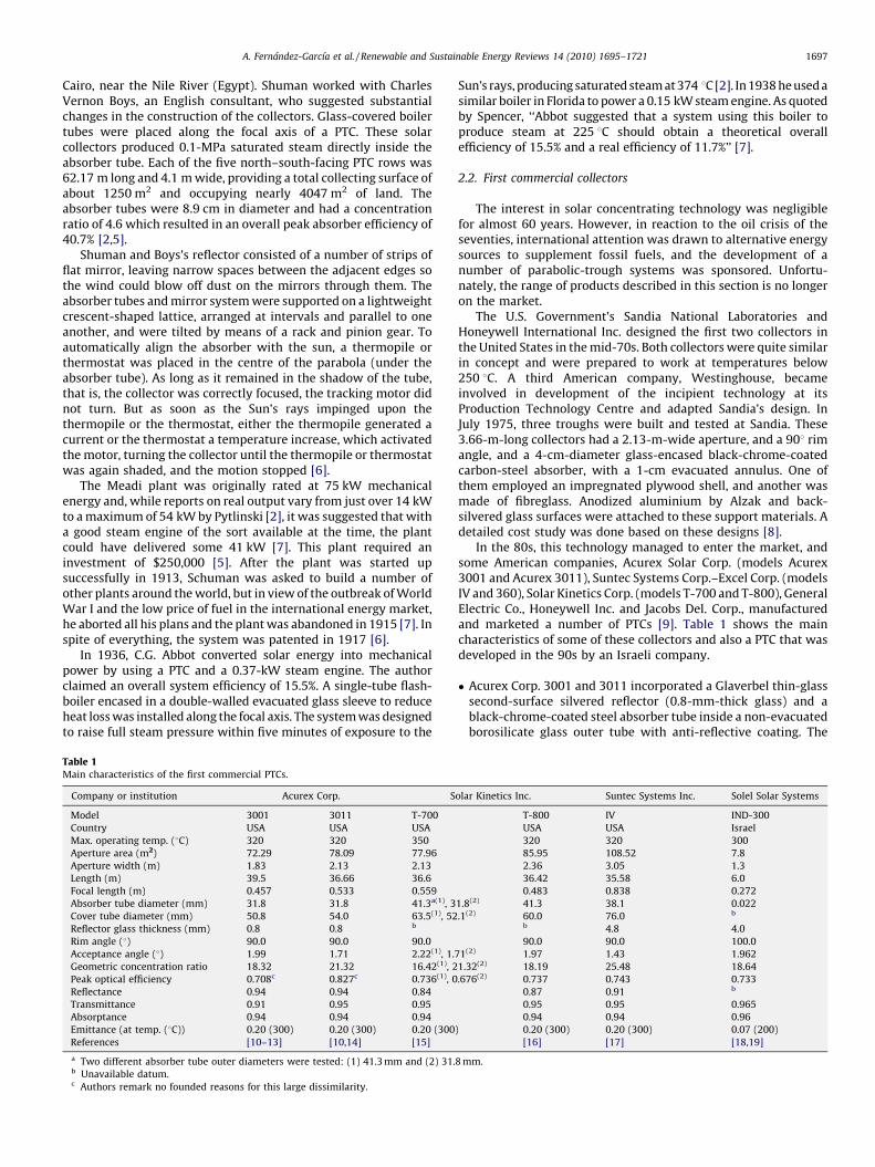
The Israeli-American company Luz International Ltd., foundedin 1979, designed three generations of PTCs, called LS-1, LS-2 andLS-3 (see Table 3 and Fig. 3), installed in Solar Electric GeneratingSystem (SEGS) plants (see Section 3.1.1).
The first two generations of collectors, LS-1 and LS-2, consistedof similar assemblies, mounted on a structure of similar length, butthe aperture width of the LS-2 collector was twice that of the LS-1collector. The structure is based on a rigid structural support tube,called the torque tube, which supports the steel profiles to whichthe parabolic mirrors are attached. In the LS-3, the torque tube isreplaced by a metal lattice framework, the aperture width is 14%wider than the LS-2 and collector length is doubled. Changes weremade in the pedestal and reflector supports, and the collectors arepositioned by a hydraulic control system instead of the mechanicalgear and cable system used in the LS-2. LS-3 collector design makesuse not only of previous Luz power plant experience (SEGS-I toSEGS-VI), but also mass production, cost and performancerequirements. However, SEGS plant operating experience showsthat any benefit to cost has been clearly offset by associatedperformance and maintenance issues [21,24].
The Heat Collector Element (HCE) (absorber tube) used in Luzcollectors (also manufactured by Luz) is a stainless-steel tube witha special selective coating, enclosed under vacuum by a glass tubeor envelope. Conventional glass-to-metal seals and metal bellows
Fig. 3. Front (left) and rear (rig
achieve the vacuum-tight enclosure necessary to protect theselective coating against oxidation and reduce thermal losses, andaccommodate for differences in thermal expansion between thesteel tubing and the glass envelope. The outer tube is low-ironglass (max. 0.015%) and has an anti-reflective coating on both sidesto maximize solar transmission. Hydrogen traps, often referred toas passive vacuum pumps, are installed in the vacuum cavity toabsorb the hydrogen which migrates slowly across the steel tube[24]. Getters are also added to absorb gases which permeate intothe evacuated space [26].
The selective coating used in the LS-1 and LS-2 collectors wasblack chrome, while a new ceramic-metal (cermet) layer 0.3-mmthick was applied by ionic bombardment under vacuum in the LS-3. The Luz concentrators are low-iron, back-silvered glass (4-mmthick) protected by five coatings (one copper, four varnish),manufactured by Flabeg Solar Int. (formerly Pilkington Solar Int.,Germany). The glass is given its parabolic shape by heating it onaccurate parabolic moulds in special ovens. Ceramic pads arecemented with a special adhesive to the back of the reflectors formounting to the support structure [21,24,25].
In 1991 Luz filed for bankruptcy and in 1992, Solel Belgium(nowadays Solel Solar Systems Ltd.) purchased Luz manufacturingassets, providing a reserve for the Luz collector technology and keycollector components [21]. Before the demise of Luz, the companyhad designed a forth generation collector, the LS-4, with theintention of studying DSG inside the absorber tubes. The LS-4collector had a 10.5-m aperture width (almost double the LS-3),
ht) views of LS-3 collector.
A. Fernandez-Garcıa et al. / Renewable and Sustainable Energy Reviews 14 (2010) 1695–17211700
49 m total length and absorber outer diameter of 0.114 m. Workingfluid temperature and pressure foreseen were 400 8C and 10 MPa,respectively. Two special features were that the absorber tube wastilted 88 and did not move, because at that time, no ball joints wereable to work at such pressures. A previous prototype, the LS4-A2,had successfully been mounted and tested in the framework of theAdvanced Trough System (ATS) Project in the Luz test facilities inJerusalem (Israel). This prototype was similar in size to the LS-3,but the absorber tube was carbon steel instead of stainless steal,and the inner absorber diameter was 0.059 m instead of 0.066 m.Unfortunately, the company disappeared before finishing thisproject and the LS-4 collector never reached the market [24,26–28].
2.3.2. EuroTrough collector
In 1998, a consortium of European companies and researchlaboratories (Abengoa/Inabensa, Fichtner Solar, Flabeg Solar Int.,Schlaich Bergermann und Partner, Iberdrola, Solel Solar Systems,CIEMAT, CRES and DLR) was created to develop a new generation ofPTCs for cost-efficient CSP plants, since the current LS-3 design wasno longer competitive [21,29].
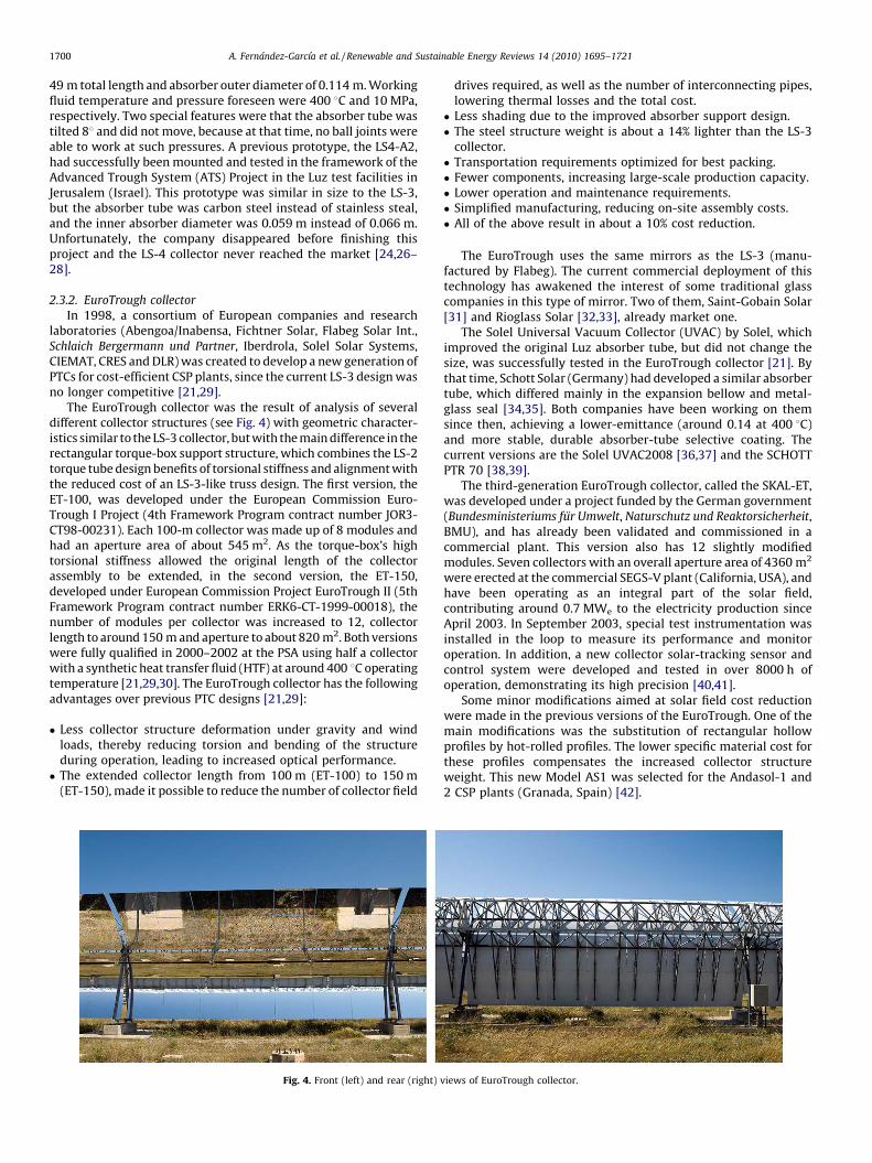
The EuroTrough collector was the result of analysis of severaldifferent collector structures (see Fig. 4) with geometric character-istics similar to the LS-3 collector, but with the main difference in therectangular torque-box support structure, which combines the LS-2torque tube design benefits of torsional stiffness and alignment withthe reduced cost of an LS-3-like truss design. The first version, theET-100, was developed under the European Commission Euro-Trough I Project (4th Framework Program contract number JOR3-CT98-00231). Each 100-m collector was made up of 8 modules andhad an aperture area of about 545 m2. As the torque-box’s hightorsional stiffness allowed the original length of the collectorassembly to be extended, in the second version, the ET-150,developed under European Commission Project EuroTrough II (5thFramework Program contract number ERK6-CT-1999-00018), thenumber of modules per collector was increased to 12, collectorlength to around 150 m and aperture to about 820 m2. Both versionswere fully qualified in 2000–2002 at the PSA using half a collectorwith a synthetic heat transfer fluid (HTF) at around 400 8C operatingtemperature [21,29,30]. The EuroTrough collector has the followingadvantages over previous PTC designs [21,29]:
� Less collector structure deformation under gravity and windloads, thereby reducing torsion and bending of the structureduring operation, leading to increased optical performance.� The extended collector length from 100 m (ET-100) to 150 m
(ET-150), made it possible to reduce the number of collector field
Fig. 4. Front (left) and rear (right)
drives required, as well as the number of interconnecting pipes,lowering thermal losses and the total cost.� Less shading due to the improved absorber support design.� The steel structure weight is about a 14% lighter than the LS-3
collector.� Transportation requirements optimized for best packing.� Fewer components, increasing large-scale production capacity.� Lower operation and maintenance requirements.� Simplified manufacturing, reducing on-site assembly costs.� All of the above result in about a 10% cost reduction.
The EuroTrough uses the same mirrors as the LS-3 (manu-factured by Flabeg). The current commercial deployment of thistechnology has awakened the interest of some traditional glasscompanies in this type of mirror. Two of them, Saint-Gobain Solar[31] and Rioglass Solar [32,33], already market one.
The Solel Universal Vacuum Collector (UVAC) by Solel, whichimproved the original Luz absorber tube, but did not change thesize, was successfully tested in the EuroTrough collector [21]. Bythat time, Schott Solar (Germany) had developed a similar absorbertube, which differed mainly in the expansion bellow and metal-glass seal [34,35]. Both companies have been working on themsince then, achieving a lower-emittance (around 0.14 at 400 8C)and more stable, durable absorber-tube selective coating. Thecurrent versions are the Solel UVAC2008 [36,37] and the SCHOTTPTR 70 [38,39].
The third-generation EuroTrough collector, called the SKAL-ET,was developed under a project funded by the German government(Bundesministeriums fur Umwelt, Naturschutz und Reaktorsicherheit,BMU), and has already been validated and commissioned in acommercial plant. This version also has 12 slightly modifiedmodules. Seven collectors with an overall aperture area of 4360 m2
were erected at the commercial SEGS-V plant (California, USA), andhave been operating as an integral part of the solar field,contributing around 0.7 MWe to the electricity production sinceApril 2003. In September 2003, special test instrumentation wasinstalled in the loop to measure its performance and monitoroperation. In addition, a new collector solar-tracking sensor andcontrol system were developed and tested in over 8000 h ofoperation, demonstrating its high precision [40,41].
Some minor modifications aimed at solar field cost reductionwere made in the previous versions of the EuroTrough. One of themain modifications was the substitution of rectangular hollowprofiles by hot-rolled profiles. The lower specific material cost forthese profiles compensates the increased collector structureweight. This new Model AS1 was selected for the Andasol-1 and2 CSP plants (Granada, Spain) [42].
views of EuroTrough collector.
A. Fernandez-Garcıa et al. / Renewable and Sustainable Energy Reviews 14 (2010) 1695–1721 1701
2.3.3. Other current collectors
Other electricity production designs following the EuroTroughphilosophy have recently appeared. The main idea is to maintaincertain geometric parameters using key components available onthe market, whilst increasing the benefits and reducing costs. Thisis the philosophy behind the following collectors:
� The American company Solargenix Energy (Duke Solar until April2003), with funding from the Department of Energy (DOE), hasdeveloped two generations of PTCs (SGX1 and SGX2) in anattempt to improve efficiency and lower cost. The SGX1 collectoris patterned after the LS-2 collector, except it is twice as long.Therefore, the components (mirrors and receivers) are the same.The main effort was invested in the lightweight space framestructure, which is made entirely of aluminium and is superior interms of shipping, handling during manufacturing, field installa-tion and corrosion resistance. In addition, this collector alsoincorporates newly developed and improved subsystems, e.g.,solar-tracking controls, support pylons and drive units. Itincreases performance by 10% and decreases cost by over 20%compared to previous-generation troughs. The main advantagein the second generation, SGX2, is the reduced manufacturingtime. In 2006, 55% of Solargenix Energy was bought by theSpanish company, Acciona Solar Power [21,43–45].� The Spanish company, SENER, developed the SENERTROUGH-I
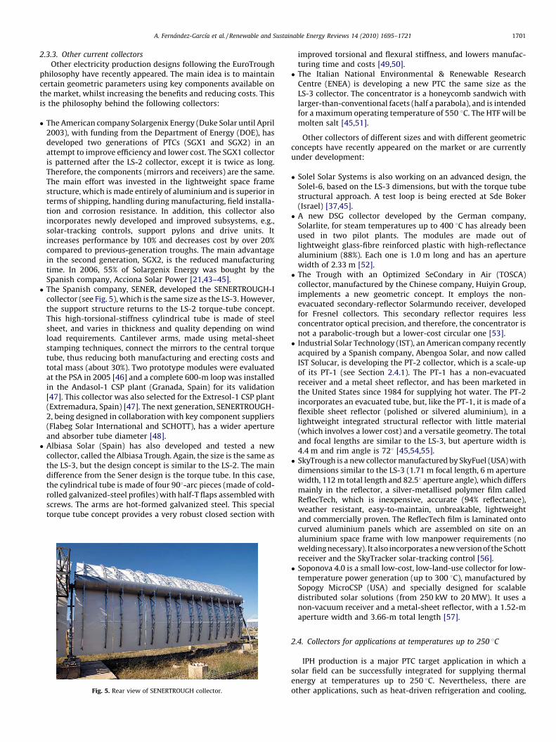
collector (see Fig. 5), which is the same size as the LS-3. However,the support structure returns to the LS-2 torque-tube concept.This high-torsional-stiffness cylindrical tube is made of steelsheet, and varies in thickness and quality depending on windload requirements. Cantilever arms, made using metal-sheetstamping techniques, connect the mirrors to the central torquetube, thus reducing both manufacturing and erecting costs andtotal mass (about 30%). Two prototype modules were evaluatedat the PSA in 2005 [46] and a complete 600-m loop was installedin the Andasol-1 CSP plant (Granada, Spain) for its validation[47]. This collector was also selected for the Extresol-1 CSP plant(Extremadura, Spain) [47]. The next generation, SENERTROUGH-2, being designed in collaboration with key component suppliers(Flabeg Solar International and SCHOTT), has a wider apertureand absorber tube diameter [48].� Albiasa Solar (Spain) has also developed and tested a new
collector, called the Albiasa Trough. Again, the size is the same asthe LS-3, but the design concept is similar to the LS-2. The maindifference from the Sener design is the torque tube. In this case,the cylindrical tube is made of four 908-arc pieces (made of cold-rolled galvanized-steel profiles) with half-T flaps assembled withscrews. The arms are hot-formed galvanized steel. This specialtorque tube concept provides a very robust closed section with
Fig. 5. Rear view of SENERTROUGH collector.
improved torsional and flexural stiffness, and lowers manufac-turing time and costs [49,50].� The Italian National Environmental & Renewable Research
Centre (ENEA) is developing a new PTC the same size as theLS-3 collector. The concentrator is a honeycomb sandwich withlarger-than-conventional facets (half a parabola), and is intendedfor a maximum operating temperature of 550 8C. The HTF will bemolten salt [45,51].
Other collectors of different sizes and with different geometricconcepts have recently appeared on the market or are currentlyunder development:
� Solel Solar Systems is also working on an advanced design, theSolel-6, based on the LS-3 dimensions, but with the torque tubestructural approach. A test loop is being erected at Sde Boker(Israel) [37,45].� A new DSG collector developed by the German company,
Solarlite, for steam temperatures up to 400 8C has already beenused in two pilot plants. The modules are made out oflightweight glass-fibre reinforced plastic with high-reflectancealuminium (88%). Each one is 1.0 m long and has an aperturewidth of 2.33 m [52].� The Trough with an Optimized SeCondary in Air (TOSCA)
collector, manufactured by the Chinese company, Huiyin Group,implements a new geometric concept. It employs the non-evacuated secondary-reflector Solarmundo receiver, developedfor Fresnel collectors. This secondary reflector requires lessconcentrator optical precision, and therefore, the concentrator isnot a parabolic-trough but a lower-cost circular one [53].� Industrial Solar Technology (IST), an American company recently
acquired by a Spanish company, Abengoa Solar, and now calledIST Solucar, is developing the PT-2 collector, which is a scale-upof its PT-1 (see Section 2.4.1). The PT-1 has a non-evacuatedreceiver and a metal sheet reflector, and has been marketed inthe United States since 1984 for supplying hot water. The PT-2incorporates an evacuated tube, but, like the PT-1, it is made of aflexible sheet reflector (polished or silvered aluminium), in alightweight integrated structural reflector with little material(which involves a lower cost) and a versatile geometry. The totaland focal lengths are similar to the LS-3, but aperture width is4.4 m and rim angle is 728 [45,54,55].� SkyTrough is a new collector manufactured by SkyFuel (USA) with
dimensions similar to the LS-3 (1.71 m focal length, 6 m aperturewidth, 112 m total length and 82.58 aperture angle), which differsmainly in the reflector, a silver-metallised polymer film calledReflecTech, which is inexpensive, accurate (94% reflectance),weather resistant, easy-to-maintain, unbreakable, lightweightand commercially proven. The ReflecTech film is laminated ontocurved aluminium panels which are assembled on site on analuminium space frame with low manpower requirements (nowelding necessary). It also incorporates a new version of the Schottreceiver and the SkyTracker solar-tracking control [56].� Soponova 4.0 is a small low-cost, low-land-use collector for low-
temperature power generation (up to 300 8C), manufactured bySopogy MicroCSP (USA) and specially designed for scalabledistributed solar solutions (from 250 kW to 20 MW). It uses anon-vacuum receiver and a metal-sheet reflector, with a 1.52-maperture width and 3.66-m total length [57].
2.4. Collectors for applications at temperatures up to 250 8C
IPH production is a major PTC target application in which asolar field can be successfully integrated for supplying thermalenergy at temperatures up to 250 8C. Nevertheless, there areother applications, such as heat-driven refrigeration and cooling,
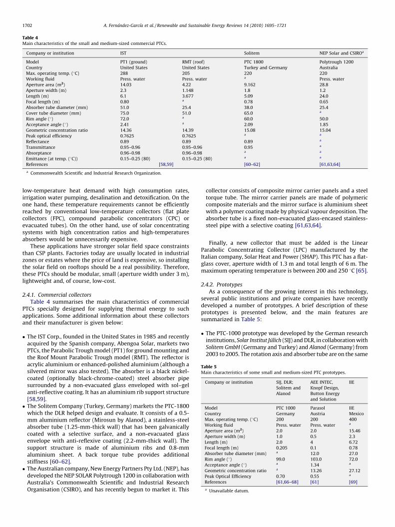
Table 5Main characteristics of some small and medium-sized PTC prototypes.
Company or institution SIJ, DLR;
Solitem and
Alanod
AEE INTEC,
Knopf Design,
Button Energy
and Solution
IIE
Model PTC 1000 Parasol IIE
Country Germany Austria Mexico
Max. operating temp. (8C) 200 200 400
Working fluid Press. water Press. water a
Aperture area (m2) 2.0 2.0 15.46
Aperture width (m) 1.0 0.5 2.3
Length (m) 2.0 4 6.72
Focal length (m) 0.205 0.1 0.78
Absorber tube diameter (mm) a 12.0 27.0
Rim angle (8) 99.0 103.0 72.0
Acceptance angle (8) a 1.34 a
Geometric concentration ratio a 13.26 27.12
Peak Optical Efficiency 0.70 0.55 a
References [61,66–68] [61] [69]
a Unavailable datum.
Table 4Main characteristics of the small and medium-sized commercial PTCs.
Company or institution IST Solitem NEP Solar and CSIROa
Model PT1 (ground) RMT (roof) PTC 1800 Polytrough 1200
Country United States United States Turkey and Germany Australia
Max. operating temp. (8C) 288 205 220 220
Working fluid Press. water Press. water a Press. water
Aperture area (m2) 14.03 4.22 9.162 28.8
Aperture width (m) 2.3 1.148 1.8 1.2
Length (m) 6.1 3.677 5.09 24.0
Focal length (m) 0.80 a 0.78 0.65
Absorber tube diameter (mm) 51.0 25.4 38.0 25.4
Cover tube diameter (mm) 75.0 51.0 65.0 a
Rim angle (8) 72.0 a 60.0 50.0
Acceptance angle (8) 2.41 a 2.09 1.85
Geometric concentration ratio 14.36 14.39 15.08 15.04
Peak optical efficiency 0.7625 0.7625 a a
Reflectance 0.89 0.89 0.89 a
Transmittance 0.95–0.96 0.95–0.96 0.95 a
Absorptance 0.96–0.98 0.96–0.98 a a
Emittance (at temp. (8C)) 0.15–0.25 (80) 0.15–0.25 (80) a a
References [58,59] [60–62] [61,63,64]
a Commonwealth Scientific and Industrial Research Organization.
A. Fernandez-Garcıa et al. / Renewable and Sustainable Energy Reviews 14 (2010) 1695–17211702
low-temperature heat demand with high consumption rates,irrigation water pumping, desalination and detoxification. On theone hand, these temperature requirements cannot be efficientlyreached by conventional low-temperature collectors (flat platecollectors (FPC), compound parabolic concentrators (CPC) orevacuated tubes). On the other hand, use of solar concentratingsystems with high concentration ratios and high-temperaturesabsorbers would be unnecessarily expensive.
These applications have stronger solar field space constraintsthan CSP plants. Factories today are usually located in industrialzones or estates where the price of land is expensive, so installingthe solar field on rooftops should be a real possibility. Therefore,these PTCs should be modular, small (aperture width under 3 m),lightweight and, of course, low-cost.
2.4.1. Commercial collectors
Table 4 summarises the main characteristics of commercialPTCs specially designed for supplying thermal energy to suchapplications. Some additional information about these collectorsand their manufacturer is given below:
� The IST Corp., founded in the United States in 1985 and recentlyacquired by the Spanish company, Abengoa Solar, markets twoPTCs, the Parabolic Trough model (PT1) for ground mounting andthe Roof Mount Parabolic Trough model (RMT). The reflector isacrylic aluminium or enhanced-polished aluminium (although asilvered mirror was also tested). The absorber is a black nickel-coated (optionally black-chrome-coated) steel absorber pipesurrounded by a non-evacuated glass enveloped with sol–gelanti-reflective coating. It has an aluminium rib support structure[58,59].� The Solitem Company (Turkey, Germany) markets the PTC-1800
which the DLR helped design and evaluate. It consists of a 0.5-mm aluminium reflector (Mirosun by Alanod), a stainless-steelabsorber tube (1.25-mm-thick wall) that has been galvanicallycoated with a selective surface, and a non-evacuated glassenvelope with anti-reflexive coating (2.2-mm-thick wall). Thesupport structure is made of aluminium ribs and 0.8-mmaluminium sheet. A back torque tube provides additionalstiffness [60–62].� The Australian company, New Energy Partners Pty Ltd. (NEP), has
developed the NEP SOLAR Polytrough 1200 in collaboration withAustralia’s Commonwealth Scientific and Industrial ResearchOrganisation (CSIRO), and has recently begun to market it. This
collector consists of composite mirror carrier panels and a steeltorque tube. The mirror carrier panels are made of polymericcomposite materials and the mirror surface is aluminium sheetwith a polymer coating made by physical vapour deposition. Theabsorber tube is a fixed non-evacuated glass-encased stainless-steel pipe with a selective coating [61,63,64].
Finally, a new collector that must be added is the LinearParabolic Concentrating Collector (LPC) manufactured by theItalian company, Solar Heat and Power (SHAP). This PTC has a flat-glass cover, aperture width of 1.3 m and total length of 6 m. Themaximum operating temperature is between 200 and 250 8C [65].
2.4.2. Prototypes
As a consequence of the growing interest in this technology,several public institutions and private companies have recentlydeveloped a number of prototypes. A brief description of theseprototypes is presented below, and the main features aresummarized in Table 5:
� The PTC-1000 prototype was developed by the German researchinstitutions, Solar Institut Julich (SIJ) and DLR, in collaboration withSolitem GmbH (Germany and Turkey) and Alanod (Germany) from2003 to 2005. The rotation axis and absorber tube are on the same
A. Fernandez-Garcıa et al. / Renewable and Sustainable Energy Reviews 14 (2010) 1695–1721 1703
axis and, therefore, the absorber is in a fixed position duringoperation, avoiding flexible pipe connections. The reflector is asilver-coated aluminium sheet (Mirosilver by Alanod), the supportstructure is stainless steel, and the absorber tube is the VacuumStandard Sydney tube by Linuo-Paradigma [66]. This collector hasan anti-reflective glass cover by Flabeg Solar International. Bothends are reflecting surfaces to avoid collector end losses [61,67]. InMarch 2007, the SIJ started another research project with fourGerman industrial partners to improve its technical characteristicsand thermodynamic performance [68].� The Parasol prototype, under development at the Austrian
Institute for Sustainable Technologies (AEE INTEC), in collabora-tion with the Austrian companies Knopf Design, Button Energy
Energiesystem GmbH and Solution Solartechnik GmbH, has aparabolic glass concentrator with an inner aluminium mirror byAlanod. The trough is covered by a flat glass that prevents dirtfrom entering and ensures stability. The stationary absorber tubeis at the collector centre of gravity. The absorber is a non-evacuated, glass-covered, stainless-steel tube with a selectivecoating. After the first tests, a second prototype was manufac-tured, with improved low-iron safety glass instead of standardwindow glass, Poligrat absorber coating instead of solar varnish,more precise positioning of the absorber tube, and 12 mmabsorber diameter instead of 8 mm [61].� The Instituto de Investigaciones Electricas (IIE), Mexico, started to
develop a PTC prototype for IPH in 2001. The support structure istubular steel, the reflective surface is 0.5-mm anodized-aluminum sheet, and the absorber is a steel-tube painted blackand surrounded by a non-evacuated Pyrex glass tube. A secondimproved prototype was developed, with a lighter supportstructure. The solar-tracking unit was moved from the end of thecollector to the middle in order to balance the torsion, and thereceiver supports were changed from a combination of viton andneoprene to Teflon. This second prototype was installed in anindustrial laundry in the north of Mexico in 2003. At the end of2004, an automobile company requested the IIE to construct andinstall 2 PTCs (with Pyromark selective coating) for sanitarywater heating [69].
3. Applications
3.1. CSP plants
Both world total final energy consumption and world CO2
emissions have doubled in the last 35 years [70]. The limitedsupply of fossil hydrocarbon resources and the negative impact ofCO2 emissions on the global environment dictate increased usageof renewable energy resources. CSP is the most likely candidate forproviding the majority of this renewable energy, because it isamongst the most cost-effective renewable electricity technolo-gies and can make a substantial contribution towards internationalcommitments to reduce the increase in the level of greenhousegases and their contribution to climate change [71,72]. Further-more, many countries are exploring various sources of renewableenergy to reduce their dependence on foreign imports to meettheir energy requirements. As solar energy is the most abundantand geographically widespread resource, it offers advantages overother energy resources [73].
To emphasize the magnitude of the solar resource, anillustrative calculation is useful. Even under the assumption thatonly 1% of the land area in the world with enough solar radiationwere used for CSP plants, the potential annual electricitygeneration would still be higher than total world electricityproduction in the year 2000 [26], and regarding environmentalbenefits, each square meter of solar field is enough to avoid theannual emissions of 200–300 kg of CO2 [71].
Appropriate site locations for CSP plants are normally in arid tosemi-arid regions, where the DNI resource is very high, becauseacceptable production costs of commercial CSP plants are typicallywhere DNI exceeds about 1700 kWh/m2year [26] or 2000 kWh/m2 year [71]. Typical site regions with these conditions are locatedin the ‘‘solar belt’’ within 408 latitude north and south. Therefore,the most promising areas in the world include the North AfricanDesert, the Arabian Peninsula, major portions of India, central andwestern Australia, the high plateaus of the Andean states, north-eastern Brazil, northern Mexico and, of course, the United StatesSouthwest. Promising site locations in Europe are found insouthern Spain and several Mediterranean islands [26]. Allcommercial CSP plants are north–south oriented, because thismaximizes the amount of power produced along the year. Thehigher the latitude, the more necessary this becomes.
There are two ways to integrate a PTC solar field in a steam-turbine power plant, directly, that is, generating steam in the solarfield (DSG technology), or indirectly, by heating thermal oil in thesolar field and using it to generate steam in a heat exchanger (HTFtechnology). In both cases, solar fields can drive all types of steam-turbine power plant cycles, Rankine with Superheat (RS), Rankinewith Reheat (RR) and Rankine with Regeneration (RRg). Anotheroption is an Organic Rankine Cycle (ORC), which generates vapourfrom an organic fluid instead of steam in a lower-temperaturecycle. Hybridising with fossil fuels can be done in several ways,using an auxiliary system for heating the HTF during low and non-solar hours, or introducing the fossil back-up in the steam cycle, inthe evaporation, superheat or reheat zones.
Another interesting option is incorporation of a solar system ina combined cycle (CC), called Integrated Solar Combined-CycleSystem (ISCCS), in which two different thermodynamic cycles, asteam-turbine Rankine cycle and gas-turbine Brayton cycle, arecombined in a single system through a Heat Recovery SteamGenerator (HRSG). Fuel is combusted in the gas turbine in theconventional way, and the hot exhaust gas goes through the HRSG.Here the energy from the gas generates and superheats steam to beused in the steam-turbine bottoming cycle. Solar energy from aPTC solar field can be integrated either at high pressure in the HRSGor at lower pressure directly in the low pressure casing of thesteam turbine [26]. The general concept is an oversized steamturbine, using solar heat for steam generation and gas turbinewaste heat for preheating and superheating steam [74].
Since the solar steam is only feeding the CC steam turbine,which is a third of its total power, the solar share is about 10% [75].Some studies show that the ISCCS configuration could reduce thecost of solar power by as much as 22% over the blended (25% fossil)cost of power from a conventional CSP plant of similar size [76]. Inaddition, an ISCCS offers three other advantages. The solar energyto electricity conversion is more efficient, the incremental costs fora larger steam turbine are less than the overall unit cost in a solar-only plant, and an integrated plant does not have the thermalinefficiencies associated with the daily steam turbine start-up andshut-down [77].
3.1.1. SEGS plants
The first oil crisis in the early 70s marked the beginning ofmodern development of CSP plants worldwide. R&D activities werestarted on several continents, and experimental and pilot solarpower plants were erected and operated. But it was in the UnitedStates where parabolic-trough solar technology reached its max-imum maturity, in nine commercial SEGS plants built in the MojaveDesert in California (where the average DNI is up to 2727 kWh/m2 year). These plants, developed by Luz International Ltd., range insize from 14 to 80 MWe and represent 354 MWe installed capacity.Current PTC technology is the most proven and lowest-cost large-scale solar power technology, primarily because of these plants [21].
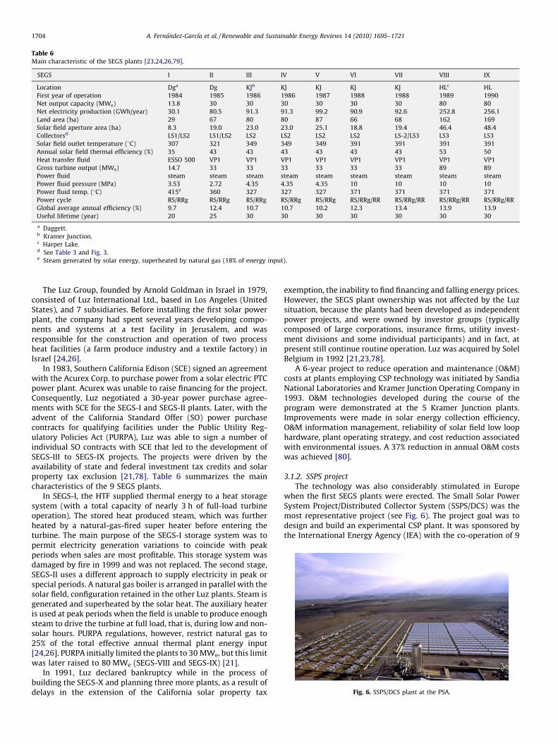
Table 6Main characteristic of the SEGS plants [23,24,26,79].
SEGS I II III IV V VI VII VIII IX
Location Dga Dg KJb KJ KJ KJ KJ HLc HL
First year of operation 1984 1985 1986 1986 1987 1988 1988 1989 1990
Net output capacity (MWe) 13.8 30 30 30 30 30 30 80 80
Net electricity production (GWh/year) 30.1 80.5 91.3 91.3 99.2 90.9 92.6 252.8 256.1
Land area (ha) 29 67 80 80 87 66 68 162 169
Solar field aperture area (ha) 8.3 19.0 23.0 23.0 25.1 18.8 19.4 46.4 48.4
Collectorsd LS1/LS2 LS1/LS2 LS2 LS2 LS2 LS2 LS-2/LS3 LS3 LS3
Solar field outlet temperature (8C) 307 321 349 349 349 391 391 391 391
Annual solar field thermal efficiency (%) 35 43 43 43 43 43 43 53 50
Heat transfer fluid ESSO 500 VP1 VP1 VP1 VP1 VP1 VP1 VP1 VP1
Gross turbine output (MWe) 14.7 33 33 33 33 33 33 89 89
Power fluid steam steam steam steam steam steam steam steam steam
Power fluid pressure (MPa) 3.53 2.72 4.35 4.35 4.35 10 10 10 10
Power fluid temp. (8C) 415e 360 327 327 327 371 371 371 371
Power cycle RS/RRg RS/RRg RS/RRg RS/RRg RS/RRg RS/RRg/RR RS/RRg/RR RS/RRg/RR RS/RRg/RR
Global average annual efficiency (%) 9.7 12.4 10.7 10.7 10.2 12.3 13.4 13.9 13.9
Useful lifetime (year) 20 25 30 30 30 30 30 30 30
a Daggett.b Kramer Junction.c Harper Lake.d See Table 3 and Fig. 3.e Steam generated by solar energy, superheated by natural gas (18% of energy input).
Fig. 6. SSPS/DCS plant at the PSA.
A. Fernandez-Garcıa et al. / Renewable and Sustainable Energy Reviews 14 (2010) 1695–17211704
The Luz Group, founded by Arnold Goldman in Israel in 1979,consisted of Luz International Ltd., based in Los Angeles (UnitedStates), and 7 subsidiaries. Before installing the first solar powerplant, the company had spent several years developing compo-nents and systems at a test facility in Jerusalem, and wasresponsible for the construction and operation of two processheat facilities (a farm produce industry and a textile factory) inIsrael [24,26].
In 1983, Southern California Edison (SCE) signed an agreementwith the Acurex Corp. to purchase power from a solar electric PTCpower plant. Acurex was unable to raise financing for the project.Consequently, Luz negotiated a 30-year power purchase agree-ments with SCE for the SEGS-I and SEGS-II plants. Later, with theadvent of the California Standard Offer (SO) power purchasecontracts for qualifying facilities under the Public Utility Reg-ulatory Policies Act (PURPA), Luz was able to sign a number ofindividual SO contracts with SCE that led to the development ofSEGS-III to SEGS-IX projects. The projects were driven by theavailability of state and federal investment tax credits and solarproperty tax exclusion [21,78]. Table 6 summarizes the maincharacteristics of the 9 SEGS plants.
In SEGS-I, the HTF supplied thermal energy to a heat storagesystem (with a total capacity of nearly 3 h of full-load turbineoperation). The stored heat produced steam, which was furtherheated by a natural-gas-fired super heater before entering theturbine. The main purpose of the SEGS-I storage system was topermit electricity generation variations to coincide with peakperiods when sales are most profitable. This storage system wasdamaged by fire in 1999 and was not replaced. The second stage,SEGS-II uses a different approach to supply electricity in peak orspecial periods. A natural gas boiler is arranged in parallel with thesolar field, configuration retained in the other Luz plants. Steam isgenerated and superheated by the solar heat. The auxiliary heateris used at peak periods when the field is unable to produce enoughsteam to drive the turbine at full load, that is, during low and non-solar hours. PURPA regulations, however, restrict natural gas to25% of the total effective annual thermal plant energy input[24,26]. PURPA initially limited the plants to 30 MWe, but this limitwas later raised to 80 MWe (SEGS-VIII and SEGS-IX) [21].
In 1991, Luz declared bankruptcy while in the process ofbuilding the SEGS-X and planning three more plants, as a result ofdelays in the extension of the California solar property tax
exemption, the inability to find financing and falling energy prices.However, the SEGS plant ownership was not affected by the Luzsituation, because the plants had been developed as independentpower projects, and were owned by investor groups (typicallycomposed of large corporations, insurance firms, utility invest-ment divisions and some individual participants) and in fact, atpresent still continue routine operation. Luz was acquired by SolelBelgium in 1992 [21,23,78].
A 6-year project to reduce operation and maintenance (O&M)costs at plants employing CSP technology was initiated by SandiaNational Laboratories and Kramer Junction Operating Company in1993. O&M technologies developed during the course of theprogram were demonstrated at the 5 Kramer Junction plants.Improvements were made in solar energy collection efficiency,O&M information management, reliability of solar field low loophardware, plant operating strategy, and cost reduction associatedwith environmental issues. A 37% reduction in annual O&M costswas achieved [80].
3.1.2. SSPS project
The technology was also considerably stimulated in Europewhen the first SEGS plants were erected. The Small Solar PowerSystem Project/Distributed Collector System (SSPS/DCS) was themost representative project (see Fig. 6). The project goal was todesign and build an experimental CSP plant. It was sponsored bythe International Energy Agency (IEA) with the co-operation of 9
Table 7Renewable Portfolio Standard in the United States.
State Amount Year State Amount Year
Arizona 15% 2025 Nevada 20% 2015
California 20% 2010 New Hampshire 16% 2025
Colorado 20% 2020 New Jersey 22.5% 2021
Connecticut 23% 2020 New Mexico 20% 2020
Delaware 20% 2019 New York 24% 2013
Hawaii 20% 2020 North Carolina 12.5% 2021
Illinois 25% 2025 Oregon 25% 2025
Massachusetts 4% 2009 Pennsylvania 18% 2020
Maryland 9.5% 2022 Rhode Island 15% 2020
Maine 10% 2017 Texas 5880 MW 2012
A. Fernandez-Garcıa et al. / Renewable and Sustainable Energy Reviews 14 (2010) 1695–1721 1705
countries (Austria, Belgium, Germany, Greece, Italy, Spain, Sweden,Switzerland and the United States), was designed and built by theAcurex Corp. (California, United States), M.A.N. (Munich, Germany)and Tecnicas Reunidas S. A. (Madrid, Spain), and was operated by theDeutsche Forschungs und Versuchsanstalt fur Luft und Raumfahrt
(DFVLR1). The project was begun in 1977 [81,82].The 0.5-MWe DCS plant was comprised of three solar fields an
American single-axis-tracking system manufactured by the AcurexCorp. (model Acurex 3001, see Table 1 and Fig. 1) and two Germantwo-axis-tracking systems manufactured by M.A.N. (model Helio-man 3/32, see Table 2 and Fig. 2). After heating in the solar fields,HTF (Santotherm 55 thermal oil) was pumped to the top of astorage tank, and from the tank to a steam generator to producesteam for a steam turbine (Fig. 6). Low-temperature oil wasreturned from the steam generator to the bottom of the tank,where it was pumped back to the solar fields [11,82,83].
The Acurex collector field, with a land use factor of 0.27, waseast–west oriented, had a total aperture area of 2674 m2, and wasmade of 10 two-row collector loops. The west M.A.N. field (M.A.N.-West), with a land use factor of 0.32, had a total aperture area of2688 m2 and was made of 14 collector loops. A third 10-loop 2244-m2 field (M.A.N.-East) was erected in March 1984. The mainadvantages of the M.A.N.-East field were a minimized field pipe-length layout, especially on the hot side, improved insulation andelimination of the long field pipe support (fins). The field controlwas also improved and the new field showed more stableoperating characteristics than the previous field [11,83].
The 5-MWht single thermocline storage tank was a verticalcylindrical shell about 15 m high and 4.2 m in diameter, and had aworking volume of 115 m3. A second storage system was alsoinstalled. It was a dual-medium storage tank, i.e., thermal energywas stored by means of thermal oil and cast-iron slabs. This tankconsisted mainly of a vertical-steel vessel, which contained a stackof 115 cast-iron slabs [11,83].
A steam generator and a steam turbine/generator unit were themajor power conversion subsystems. The steam generatorconsisted of a separate economizer, evaporator with a steam/water separation drum mounted above, and super heater. Thesteam turbine was an eight-stage condensing turbine with oneextraction for the deaerator manufactured by Stal-Laval. Theturbine drove the air-cooled electric generator by means of asingle-reduction parallel-shaft gear. The electric generator outputwas 577 kWe with a 0.8 power factor. The calculated overallefficiency of the turbine/generator unit was 22.7% [11,83].
This experimental plant was in operation at the PSA (Almerıa,Spain) between 1981 and 1985. The following conclusions werearrived at [83]:
� More energy was available for collection with a two-axis trackingcollector than a single-axis collector (energy supply). However,the SSPS single-axis collector was able to make better use of theenergy available to it than the two-axis systems.� The thermal efficiency in the original M.A.N. field (M.A.N.-West)
was approximately 21%, and around 30% in the new M.A.N. field(M.A.N.-East).� Thermal to electrical conversion efficiencies were much lower
than expected.� The two-axis collector systems were difficult to maintain and
required more maintenance than the single-axis collectorsystem.
3.1.3. Current state of CSP in the United States
The American Western Governors’ Association (WGA) Cleanand Diversified Energy Advisory Committee had established
1 Nowadays the DLR.
energy Task Forces on Advanced Coal, Biomass, Energy Efficiency,Geothermal, Solar, Transmission and Wind with roadmappingguidelines for implementation of 30,000 MWe of new cleandiversified energy generation by 2015, a 20% increase in energyefficiency by 2020 and build-up of adequate transmission capacityfor the region over the next 25 years. In its 2006 report to the WGA,the Solar Task Force identified 4 GWe of high-quality CSP sites inthe South Western US [75]. A number of these states have specialpolicy requirements stimulating renewable energy development,provided for the in their Renewable Portfolio Standard (RPS). A RPSis a state policy that requires electricity providers to achieve aminimum percentage of their power from renewable energies by acertain date. Table 7 shows the states with such RPS [84]. Two ofthe states in Table 7 already have commercial CPS plants (seeTable 8).
The Saguaro Station organic Rankine turbine can be operatedautomatically [85]. It was built under a federal production taxcredit available for utility ownership [79]. NSO is a solar-onlysystem with 30 min of thermal storage, used to minimize theeffects of transients, and a very small natural gas heater, mostlyused for freeze protection, because only a 2% supplement isallowed in Nevada [87]. It was built under a special powerpurchase agreement with a 30% federal investment tax credit [79].
There are also two plant projects under development. The firstone, the Solana Generating Station, will be the largest solar powerplant in the world. It will be built and operated by Abengoa Solar(Spain), which has recently signed a contract with APS. The plantwill be located on agricultural land 100 km southwest of Phoenix,near Gila Bend (Arizona), and the electricity generated will be soldto APS for 30 years. It will have a 280-MWe gross electricitycapacity, with 2 � 140-MWe conventional steam turbines andaround 250 MWe net capacity, with a 220 ha aperture area on800 ha of land. The plant will have a 6-h molten-salt thermalstorage system. It is expected to go on grid in 2011 [55,88,89].
The second plant will be located in Ivanpah (California) and willbe built and operated by BrightSource (whose subsidiary is Luz II)as the consequence of a series of contracts between Pacific Gas andElectricity Company (PG&E) and BrightSource for a total of500 MWe of power to be supplied from solar thermal power. Itwill have a 100-MWe capacity and produce 246 GWeh/year [90].
3.1.4. Current state of CSP in Europe
The most important European policy documents, in whichtargets and global strategies are specified, are the European UnionWhite Paper for a Community Strategy and Action Plan; Energy forthe Future: Renewable Sources of Energy, European UnionDirective 2001/77 on the Promotion of Electricity Produced fromRenewable Energy Sources in the Internal Market, and theEuropean Union policies for security of energy supply and forthe implementation of the Kyoto Protocol [91]. By 2010, the shareof renewable energy sources should represent 12% of the gross
Minnesota 25% 2025 Washington 15% 2020
Montana 15% 2015 Wisconsin 10% 2015
Table 8Main characteristics of current CSP plants in operation in the United States.
Plant Saguaro Solar Generating Station Nevada Solar One, NSO
Location Red Rock, near Tucson (Arizona) Boulder City, Nevada
Average solar resource (kWh/m2 year) 2000 2500
Developer Acciona Solar Powera and ORMAT Acciona Solar Power and Siemens
First year of construction 2004 2006
Operator Arizona Public Service (APS) Solargenix Energy
Power utility APS Nevada Power Company
First year of operation 2006 2007
Net output capacity (MWe) 1 64
Net electricity production (GWeh/year) 2 134
Land area (ha) 4.69 162
Solar field aperture area (ha) 1.034 35.720
Collectors SGX1 (Acciona Solar Power) SGX2 (Acciona Solar Power)
Reflectors manufacturer Flabeg Flabeg
Absorber tubes manufacturer SCHOTT (PTR 70) 62% SCHOTT (PTR 70) + 38% Solel (UVAC)
Solar field outlet temperature (8C) 290 390
Heat transfer fluid Xceltherm 600 VP1
Turbine manufacturer ORMAT (Israel) Siemens (Sweden)
Power fluid Pentane Steam
Power fluid pressure (MPa) 2.23 8.61
Power fluid temp. (8C) 204 371
Power cycle Recuperated ORC RR
Global average annual efficiency (%) 12 20
References [43,79,85] [43,44,79,86]
a Acciona Energy (Spain) purchased 55% of Solargenix Energy and formed Acciona Solar Power in 2006.
A. Fernandez-Garcıa et al. / Renewable and Sustainable Energy Reviews 14 (2010) 1695–17211706
energy consumption [92] and 22.1% of the electricity generationmix [93].
3.1.4.1. Spain. Spain, with a DNI of 2000 kWh/m2 year, is one of theinternational leaders in the implementation of CSP technology forelectricity generation [73]. Spanish legislation adopted Europeangoals in the Renewable Energies Plan, approved in 1999 (PFER) andrevised in 2005 (PER). The 1999 Plan set a goal of 200 MWe of CSPplant installed capacity by the end of 2010. This was increased to500 MWe in the 2005 Plan. European Union Directive 2001/77 wasalso adopted by the 2005 PER, setting the share of renewableenergy sources at 29.4% of the electricity generation mix in Spain[94–96].
Spanish Law 54/1997 on the electricity sector, approved in 1997[97], lays out the general lines for liberalizing this sector. This Lawprovides for a ‘‘Special Regime’’ for self-producers or facilities withinstalled capacity of 50 MWe or less based on co-generation, non-consumable renewable energies, biomass or any type of biofuel ornon-renewable waste. This Law not only introduced competitionin the Spanish electricity sector, but also made this principlecompatible with the achievement of other purposes, such asimproving energy efficiency, reducing consumption and protectingthe environment.
Royal Decree 2818/1998 [98] followed this precedent byestablishing a special legal framework for electricity productionfor Special Regime facilities based on an 18.0-cs/kWhe premiumover the market price. Although all solar facilities were included inthe special regime, only solar photovoltaic facilities received apremium and no CSP project prospered. In Royal Decree 841/2002[99], the two types of solar facilities were considered separatelyand an incentive premium of 12 cs/kWhe for solar thermal plantsbetween 100 kWe and 50 MWe capacity was introduced, subject to
Table 9Special regime incentives under the RD 436/2004 and the RD 661/2007.
RD 436/2004
Reference premium Regulated ta
First 25 years 260% TMR (21.01 cs/kWhe)a 300% TMR (2
Rest of the life 210% TMR (16.97 cs/kWhe)a 240% TMR (1
a Assuming TMR = 80.8 s/MWh.
revision every 4 years. This incentive was still not bankable and theamount did not cover the cost or risks involved for first CSP projectsto become feasible.
The solar thermal premium was therefore increased in RoyalDecree 436/2004 [100], which improved the solar thermal feed-inpremium and made CSP projects bankable and attractive forinvestors. This Royal Decree included the following features [96]:
� Power producers had two options for sale. They could eithertransfer it to the power distribution company, with theelectricity sale price stated as a single regulated tariff (tariffmodel), or sell on the free market at the going market price plus apremium (premium model). Representative data are shown inTable 9.� Maximum plant power capacity of 50 MWe. Higher capacities
must sell on the market.� 12% (tariff model) or 15% (premium model) natural gas or
propane back-up to maintain the temperature of the storagetank.� Annual adaptation to the Tarifa Media de Referencia, TMR
(average reference tariff) subject to 4-year revision.� Incentive revision after implementation of the first 200 MWe
capacity.
Spanish Royal Decree 661/2007, approved in 2007 [101],differentiated from the former in the following [75,102]:� The incentives were increased (see Table 9).� Auxiliary fuel can be used to maintain the HTF temperature to
compensate for the lack of solar radiation. No auxiliary fuel isspecified.� Annual revision to the Retail Price Index.� Conditions will be reviewed by 2010 or when 500 MWe have
been installed.
RD 661/2007
riff Reference premium Regulated tariff
4.24 cs/kWhe)a 25.40 cs/MWhe 26.94 cs/kWhe
9.39 cs/kWhe)a 20.32 cs/MWhe 21.55 cs/kWhe
A. Fernandez-Garcıa et al. / Renewable and Sustainable Energy Reviews 14 (2010) 1695–1721 1707
As a result, there is more than 10 GWe CSP capacity planned inSpain, with 2 PTC plants in operation (Andasol-I and IbersolPuertollano), 13 plants under construction (see Table 10) and morethan 200 planning projects [73,103].
Andasol-I received a s 5-million grant form the 5th Frame-work Programme of the European Union and finance from theEuropean Investment Bank [75]. Both Andasol-I and Andasol-IIhave an integrated 1010-MWht molten-salt thermal storagesystem to extend plant full-load operation 7.5 h beyond daylighthours. The storage system consists of two tanks (29,000 tons ofmolten salts) with 385 8C charge temperature and 295 8Cdischarge temperature [104,109]. In addition, the Andasol plantsalso include two 15-MWth auxiliary gas heater to heat the thermaloil when solar radiation is insufficient and to keep salt fromsolidifying.
Moreover, ACS-Cobra is constructing another three 50-MWe
plants similar to the Andasol projects, Extresol 1 (in collaborationwith Sener) and Extresol 2 in Torre de Miguel Sesmero (Badajoz),and Manchasol 1 in Alcazar de San Juan (Toledo). This company isalso planning 2 more plants, Extresol 3 in Badajoz, and Manchasol2 in Ciudad Real. Solar Millenium, in collaboration with M.A.N.Ferrostal, has recently started the construction of Andasol-III nextto the previous Andasol projects [73,103].
The Ibersol Puertollano plant (no thermal storage) has a fossil-fuel auxiliary system, for periods of low solar radiation, plantshutdowns and transitories [106]. Iberdrola is planning 11 otherplants in Spain with characteristics similar to Puertollano plant[73].
Solnova plants (no thermal storage) have a natural-gas firedHTF heater in parallel with the solar field [107,108]. Abengoa Solaris also planning another 6 plants similar to Solnova-I in Spain,Solnova-II and Solnova-V in Sanlucar la Mayor (Seville), Helios 1and Helios 2 in Ciudad Real, and Ecija 1 and Ecija 2 in Ecija (Seville)[73].
In addition to the 9 plants mentioned above, there are 5 more50-MWe plants currently under construction, La Risca in Alvarado(Badajoz) and Palma del Rıo-I in Palma del Rıo (Cordoba) byAcciona, Lebrija I in Lebrija (Seville) by Solel/Sacyr, La Florida inAlvarado (Badajoz) and La Dehesa in La Garrovilla (Badajoz) bySAMCA [73,103]. Other companies are also planning and promot-
Table 10Main characteristics of CSP plants constructed or under construction in Spain.§: Unava
Plants Andasol-I and Andasol-II
Location Marquesado de Zenete (Granada)
Average solar resource (kWh/m2 year) 2150
Owner ACS-Cobra (75%) & Solar Milennium S.A. (2
Developer ACS-Cobra and Sener
First year of construction 2006 (Andasol-I) 2007 (Andasol-II)
Operator ACS-Cobra and Sener
Power utility Sevillana Endesa
First year of operation 2008 (Andasol-I) 2009 (Andasol-II, expecte
Net output capacity (MWe) 49.9
Net electricity production (GWh/year) 179
Land area (ha) 200
Solar field aperture area (ha) 51.012
Collectors 624 SKAL-ET150/AS1
Reflectors manufacturer Flabeg
Absorber tubes manufacturer SCHOTT
Solar field outlet temperature (8C) 400
Heat transfer fluid Thermal oil (Dow thermal A)
Turbine manufacturer Siemens
Power fluid Steam
Power fluid pressure (MPa) 10
Power fluid temp. (8C) 377
Power cycle RS/RRg/RR
Global annual efficiency (%) 16
References [41,104,105]
a 90% Iberdrola Renovables, 10% Instituto para la Diversificacion y el Ahorro Energet
ing 50-MWe plants in Spain, Albiasa Solar in Saucedilla (Caceres),Acciona in Majadas de Tietar (Caceres) and Palma del Rıo(Cordoba), ARIES in Alcazar de San Juan (Ciudad Real) (Aste 1and Aste 2 plants) and Badajoz (Axtesol plant), and Torresol (60%Sener and 40% Masdar) in Seville (Termesol plant) and Cadiz(Arcosol plant) [50,73].
3.1.4.2. Italy. Italy (DNI about 2000 kWh/m2 year) has initiated thepromotion of CSP to increase the renewable energy share of totalelectricity generation. In May 2008, Italian Decree 11/4/2008 waspassed [110], establishing the criteria and ways to promote solarpower production in thermodynamic cycles. The significant pointsare:
� Incentives for electricity from solar thermal or hybrid solarpower plants without any limitations on the solar share. Theincentive tariffs to be added to the selling price are proportionalto the solar share: 28 cs/kWhe for a solar share of up to 0.15,25 cs/kWhe for a solar share between 0.15 and 0.50, and 22 cs/kWhe for a higher solar share.� Incentives remain the same for 25 years, without any adjustment
for inflation, and can be added to the grid sale price.� Incentives are valid for plants in operation before 31 December
2012. The incentive tariffs will be reduced 2% each calendar yearfor plants that start up operation between 1 January 2013 and 31December 2014. After that date, incentive tariffs will be settaking the cost of conventional fuels and solar components intoconsideration.� If the solar component is integrated with another renewable
energy source (for example biomass), the hybrid plant receives aGreen Certificate for electricity produced with renewable energysources under the Green Certificate Mechanism (today in therange of 18–22 cs/kWhe).� The national target set by the decree is a total installed collector
aperture area of 2 million square meters.� All solar power plants, hybrid plants included, must be equipped
with a thermal storage system with unitary storage capacity ofno less than 1.5 kWhth per square meter aperture.� The minimal plant collector aperture is 2500 m2, however, there
is no upper limit on plant size.
ilable datum.
Ibersol Puertollano Solnova-I, Solnova-III & Solnova-IV
Puertollano (Ciudad Real) San Lucar la Mayor (Seville)
2071 1940
5%) Iberdrola Energıa Solara Abengoa Solar
Iberdrola Energıa Solar Abengoa Solar
2007 2007 (Solnova-I) 2008 (Solnova-III and IV)
Iberdrola Energıa Solar Abengoa Solar
Iberdrola Sevillana Endesa
d) 2009 2009 (expected)
50 50
120 114.6
135 120
29.000 29.430
352 ET150 360 ET150
Flabeg Rioglass
Solel SCHOTT
390 393
Thermal oil Thermal oil
Siemens Siemens
Steam Steam
10 10
380 380
RS/RRg/RR RS/RRa 19
[106] [107,108]
ico (IDAE).
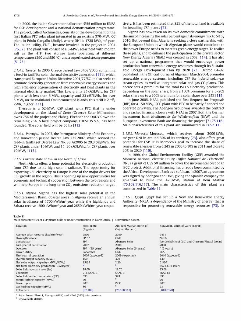
A. Fernandez-Garcıa et al. / Renewable and Sustainable Energy Reviews 14 (2010) 1695–17211708
In 2000, the Italian Government allocated s55 million to ENEAfor CSP development and a national demonstration programme.The project, called Archimedes, consists of the development of thefirst Italian PTC solar plant integrated in an existing 370-MWe CCplant in Priolo Gargallo (Sicily), where DNI is 1725 kWh/m2 year.The Italian utility, ENEL, became involved in the project in 2004[75,87]. The plant will consist of a 5-MWe solar field with moltensalt as the HTF, two storage tanks operating at differenttemperatures (290 and 550 8C), and a superheated steam generator[51,73].
3.1.4.3. Greece. In 2006, Greece passed Law 3468/2006, containinga feed-in tariff for solar thermal electricity generation [111], whichtransposed European Union Directive 2001/77/EC. It also seeks topromote electricity generation from renewable energy sources andhigh efficiency cogeneration of electricity and heat plants in theinternal electricity market. This Law grants 25 cs/kWhe for CSPplants with less than 5 MWe capacity and 23 cs/kWhe for over5 MWe on the mainland. On unconnected islands, this tariff is 2 cs/kWhe higher [111].
Theseus is a 52-MWe CSP plant with PTC that is underdevelopment on the island of Crete (Greece). Solar Millenniumowns 75% of the project and Flabeg, Fitchner and OADYK own theremaining 25%. A local project company, THESEUS S.A., has beenfounded. The solar field will be 30 ha [112].
3.1.4.4. Portugal. In 2007, the Portuguese Ministry of the Economyand Innovation passed Decree Law 225.2007, which revised thefeed-in tariffs set Decree Law No. 33 A/2005 to 29.3 cs/kWhe forCSP plants under 10 MWe and 15–20 cs/kWhe for CSP plants over10 MWe [113].
3.1.5. Current state of CSP in the North of Africa
North Africa offers a huge potential for electricity productionfrom CSP due to its high solar irradiance. The opportunity forexporting CSP electricity to Europe is one of the major drivers forCSP growth in the region. This is opening up new opportunities foreconomic and technical cooperation between the two regions andwill help Europe in its long-term CO2-emissions reduction target.
3.1.5.1. Algeria. Algeria has the highest solar potential in theMediterranean Basin. Coastal areas in Algeria receive an annualsolar irradiance of 1700 kWh/m2 year while the highlands andSahara receive 1900 kWh/m2 year and 2650 kWh/m2 year respec-
Table 11Main characteristics of CSP plants built or under construction in North Africa. §: Unav
Location Hassi R’Mel
(Algeria)
Ain B
Oujda
Average solar resource (kWh/m2 year) 2500 2290
Owner/Developer SPP1a ONE
Constructor SPP1 Aben
First year of construction 2007 2008
Operator SPP1 (25 years) Aben
Power utility Sonatrach ONE
First year of operation 2009 (expected) 2009
Overall output capacity (MWe) 150 470
Net solar output capacity (MWth/MWe) 95/25 b/20
Net total electricity production (GWh/year) b b
Solar field aperture area (ha) 18.00 18.70
Collectors 216 SKAL-ET SKAL-
Solar field outlet temperature (8C) 393 393
Steam turbine capacity (MWe) 70 b
Power cycle ISCC ISCC
Gas turbine capacity (MWe) 80 b
References [87,108] [75,1
a Solar Power Plant 1, Abengoa (66%) and NEAL (34%) joint venture.b Unavailable datum.
tively. It has been estimated that 82% of the total land is availablefor installing CSP plants [73].
Algeria has now taken on its own domestic commitment, withthe aim of increasing the solar percentage in its energy mix to 5% by2010. But beyond this, Algeria is seeking a close partnership withthe European Union in which Algerian plants would contribute tothe power Europe needs to meet its green energy target. To realizethese plans, and to enhance the participation of the private sector,New Energy Algeria (NEAL) was created in 2002 [114]. It has alsoset up a national programme that would encourage powerproduction from renewable energy resources through its Sustain-able Energy Development Plan by 2020 [73]. Decree 04-92,published in the Official Journal of Algeria in March 2004, promotesrenewable energy systems, including CSP for hybrid solar-gassteam cycles, as well as integrated solar and gas-CC plants. Thisdecree sets a premium for the total ISCCS electricity production,depending on the solar share, from a 100% premium for a 5–20%solar share up to a 200% premium for a solar share over 25% [115].
In June 2005, NEAL published the first Request for Proposals(RfP) for a 150 MWe ISCC plant with PTC to be partly financed andoperated privately. The Abengoa Group was awarded the contractand reached financial closure with NEAL in 2007. Both the Germaninvestment bank Kreditanstals fur Wiederaufbau (KfW) and theEuropean Investment Bank are financing the project [71,75,116].Main characteristics of this plant are summarized in Table 11.
3.1.5.2. Morocco. Morocco, which receives about 2000 kWh/m2 year DNI in around 30% of its territory [73], also offers greatpotential for CSP. It is Morocco’s goal to increase the share ofrenewable energies from 0.24% in 2003 to 10% in 2011 and close to20% in 2020 [116].
In 1999, the Global Environment Facility (GEF) awarded theMorocco national electric utility (Office National de l’Electricite,ONE) a grant of US$ 50 million to cover the incremental cost of anISCC project. Additional financing has already been committed bythe African Development Bank as a soft loan. In 2007, an agreementwas signed by Abengoa and ONE, giving the Spanish company thego-ahead to build the 470 MWe station at Beni Mathar[75,108,116,117]. The main characteristics of this plant aresummarized in Table 11.
3.1.5.3. Egypt. Egypt has set up a New and Renewable EnergyAuthority (NREA, a dependency of the Ministry of Energy) that isresponsible for promoting renewable energy resources [73]. Its
ailable datum.
eni Mathar, north of
(Morocco)
Kuraymat, south of Cairo (Egypt)
2431
NREA
goa Solar Iberdrola/Mitsui (CC) and Orascum/Flagsol (solar)
2008
goa Solar (5 years) b (2 years)
EEA
(expected) 2010 (expected)
140
61/20
852 (33.4 solar)
13.08
ET SKAL-ET
393
76
ISCC
73
08,117] [40,87,120]
A. Fernandez-Garcıa et al. / Renewable and Sustainable Energy Reviews 14 (2010) 1695–1721 1709
renewable energy strategy currently targets a 3% share of theEgyptian electricity demand, mainly from solar, wind and biomassapplications, by 2010, with additional contributions from otherrenewable energy applications [116].
In 1995, the NREA and the Egyptian Electricity Authority (EEA)funded a technological feasibility study for an ISCCS in Egypt,where more than 95% of the territory receives over 2000 kWh/m2 year DNI, and about 80% of the land is available for use. Threesolar technologies were considered mature for large-scaleapplication, the PTC, the air receiver power tower and themolten-salt receiver power tower. The study concluded that theISCCS with PTCs or air tower are equally attractive [118]. This wasfollowed by a SolarPACES START mission in 1996. The Ministry ofElectricity and Energy (MOEE) entrusted a joint NREA, MOEE andEEA committee with the evaluation of the potential for integratingCSP technologies into the Egyptian electricity network. Thecommittee concluded that the ISCCS with PTC is the mosteconomical near-term approach for beginning implementationof solar thermal power in Egypt [119].
A project to build an ISSC plant with PTC has been underwaysince then. The project received a US$ 50 million grant from theGEF to cover the incremental cost of the solar power plant. TheNREA contracted two consortia to build the CC and the solar field inSeptember 2007 (see Table 11) [40,75,116,120].
3.1.6. Current state of CSP in the Middle East
Middle East countries are developing solar power capabilities asa consequence of estimated power shortages from large-scaleconstruction, and rising concern about the longevity of fossil fuels.Almost all Middle East territory is exposed to high solar irradiancelevels (around 2400 kWh/m2 year in Israel, Jordan and SaudiArabia). Potential for export is also being explored by thesecountries with the European Union [73].
3.1.6.1. Israel. The Israeli Ministry of National Infrastructure,which is responsible for the energy sector, decided in 2002 tomake CSP a strategic share of the Israeli power market, with aminimal power unit of 100 MWe, and the option of increasing theCSP contribution up to 500 MWe by 2010, and 1000 MWe by 2020.Israel has also committed an increased share in alternative andrenewable energies to at least 15–20% by 2020. In September 2006,new feed-in incentives for solar-driven independent powerprojects (IPP) valid for 20 years were announced. The tariff isapproximately 16.3 US$cents/kWh, for plants with installedcapacity over 20 MWe. For smaller plants, from 100 kWe to20 MWe range, the tariff is 20.4 US$cents/kWh. The regulationsfurther stipulate that a fossil fuel back-up of less than 30% of totalcapacity is allowed [121].
There are plans to build a new solar station in The Negev desert,which covers 55% of Israel’s land, every year for the next 20 years[71,73,87,121]. The first 150-MWe CSP plant with PTC will beprobably built by Solel Solar Systems at Ashalim, in the Negevdesert. The plant will use 70% solar energy and 30% natural gas. Theproject is managed by Israel Electric Company and the final ownerwill be an IPP [19,116].
3.1.6.2. Iran. Iran has been promoting a CSP plant since 1994,when a Joint German-Iranian Expert Group on Solar ThermalPower, sponsored by the German Federal Ministry of Environmentand the Iranian Power Development Company (IPDC), did aconcept study for a 100-MWe CSP plant. In 1996 IPDC contacted theGEF for funding the incremental cost of the solar field, however, theGEF was not in a position to allocate the additional resourcesneeded. A feasibility study on ISCC with PTC was done by theNIROO Research Institute, FLABEG Solar and Fichtner Solar. Yazdwas chosen as the most preferred site with 2511 kWh/m2 year DNI.
Due to the lack of GEF funding, Iran changed the plantconfiguration in 2005, and now intends to build a 20-MWe
(67 MWth) solar field in a 300-MWe natural-gas-fired CC plant[116,122,123].
3.1.6.3. UAE. The UAE offers excellent solar resources for CSP,receiving an average DNI of around 2200 kWh/m2 year. The factthat CSP requires vast areas of land and that land is scarce andexpensive in this country, could make it difficult for CSP to be acost-effective option for producing electricity. According to a UAEgovernment document, renewable energy could contribute 6–7%of the peak demand by 2020 [73]. A 100-MWe PTC plant, calledShams 1, is being planned by Masdar in Abu Dhabi [124].
3.1.7. Current state of CSP in other countries
3.1.7.1. India. The Rajasthan Renewable Energy Corporation(RREC) published an RfP in June 2002 for a 140 MWe ISCCS,integrating a PTC field of about 22 ha to supply a solar share of30 MWe. Solar radiation in the region selected (Mathania,Rajasthan, near Jodhpur) is around 2240 kWh/m2 year DNI. Theincremental solar costs were to be covered by a GEF grant forUS$49 million with further financing by a soft loan from theGerman Investment Bank (KfW), and loans from India and the stateof Rajasthan. Limited competition, high risks on uncertain fossilfuel supply and some government disputes delayed the project.After extensive review of the underlying technical and projectimplementation concept, GEF is now requesting that all Indianparticipants reaffirm their commitment to continue the project[71,87,116].
3.1.7.2. Mexico. Mexico’s Comision Federal de Electricidad (CFE)issued an RfP in 2002 for a 250-MWe gas-fired CC plant with anoptional integrated 25 MWe PTC field. The incremental solar costsshould be covered by a GEF grant. As investor response to thisconcept was very limited, in 2003 it was decided that anEngineering Procurement and Construction (EPC) scheme withCFE and GEF grants should be pursued, and the solar field would nolonger be an option but compulsory. At first, the plant location wasCerro Prieto, near Mexicali in Baja California Norte (DNI about2600 kWh/m2 year), but in 2005 the site for the CC plant, calledAgua Prieta II, was moved to Sonora, and it was suggested by theCFE that its size be doubled from 250 to 500 MWe [71,116]. Thefinal ISCC will have a 480 MWe capacity and the solar field capacitywill be 31 MWe (peak).
3.1.7.3. Brazil. Brazil has extensive, semi-arid regions receiving aDNI on the order of 2200 kWh/m2 year. The highest potentialradiation is in the Sao Francisco River Basin and the Sobradinhoarea in the Northeast. Potential sites in Brazil are close to theequator with the consequential optical advantage. Immenseland areas are available for solar thermal applications. Januariaand Itacarambi have excellent topographic conditions, gridaccess, cooling water, road access, low wind speeds, andmoderate ambient temperatures with little daily variation.These sites receive annual direct solar radiation from 1800 to2300 kWh/m2 and can easily accommodate large-scale solarpower plants [87].
In 1997, a SolarPACES START Mission went to Brazil. Accordingto this report, Luz and Flagsol initiated SEGS-project developmentactivities in Brazil in 1989 and for this purpose formed aconsortium with ABB do Brazil and the Tenenge/Odebrecht group.The consortium performed site surveys and pre-feasibility studies,but no project came out of it. Both off-grid village and irrigationloads and grid-connected power for cities are promising marketsfor the deployment of CSP in Brazil [125].
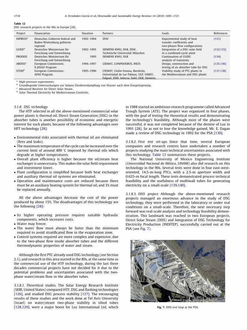
Table 12DSG research projects in the 90s in Europe [28].
Project Financiation Duration Partners Goals References
HIPRESSa Deutsches Gobierno federal and
Baden-Wutemburg gobierno
regional
1992–1994 ZSW Experimental study of heat
transfer coefficients and
two-phases flow configurations
[131]
GUDEb Deutsches Ministerium fur
Forschung und Entwicklung
1992–1995 SIEMENS KWU, DLR, ZSW,
Technische Universitat Munchen
Integration of a DSG solar field
in a combined-cycle plant
[132,133]
PRODISS Deutsches Ministerium fur
Forschung und Entwicklung
1995 SIEMENS KWU, DLR Continuation of GUDE;
analysis of transients
[134]
ARDISSc European Commission;
II JOULE Program
1994–1997 CIEMAT, CONPHOEBUS, INETI Design, construction and
testing of an absorber tube for DSG
[135,136]
STEMd European Commission;
APAS Program
1995–1996 CIEMAT, Union Fenosa, Iberdrola,
Universidad de Las Palmas, ULP, UMIST,
Falgsol, ZSW, Intecsa, Solel, DLR, Siemens
Viability study of PTC plants in
the Mediterranean and DSG plants
[137,138]
a High pressure experiments.b Grundlegende Untersuchungen zur Solares Direktverdampfung von Wasser nach dem Einspritzprinzip.c Advanced Receiver for Direct Solar Steam.d Solar Thermal Electricity for Mediterranean Countries.
Fig. 7. DISS test loop at the PSA.
A. Fernandez-Garcıa et al. / Renewable and Sustainable Energy Reviews 14 (2010) 1695–17211710
3.1.8. DSG technology
The HTF selected in all the above-mentioned commercial solarpower plants is thermal oil. Direct Steam Generation (DSG) in theabsorber tubes is another possibility of economic and energeticinterest for such plants, because of the following advantages overHFT technology [28]:
� Environmental risks associated with thermal oil are eliminated(fires and leaks).� The maximum temperature of the cycle can be increased over the
current limit of around 400 8C imposed by thermal oils whichdegrade at higher temperatures.� Overall plant efficiency is higher because the oil/steam heat
exchanger is unnecessary. This makes the solar field requirementand investment lower.� Plant configuration is simplified because both heat exchanger
and auxiliary thermal oil systems are eliminated.� Operation and maintenance costs are reduced because there
must be an auxiliary heating system for thermal oil, and 3% mustbe replaced annually.
All the above advantages decrease the cost of the powerproduced by about 15%. The disadvantages of this technology arethe following [28]:
� Its higher operating pressure requires suitable hydrauliccomponents, which increases costs.� Water may freeze.� The water flow must always be faster than the minimum
required to avoid stratificated flow in the evaporation zone.� Control systems required are more complex and expensive, due
to the two-phase flow inside absorber tubes and the differentthermodynamic properties of water and steam.
Although the first PTC already used DSG technology (see Section2.1), and research in this area started in the 80s, at the same time asthe commercial use of the HTF technology, during the last threedecades commercial projects have not decided for it due to thepotential problems and uncertainties associated with the two-phase water/steam flow in the absorber tubes.
3.1.8.1. Theoretical studies. The Solar Energy Research Institute(SERI, United States) compared HTF, DSG and flashing technologies[126], and studied DSG process stability [127]. The encouragingresults of these studies and the work done at Tel Aviv University(Israel) on water/steam two-phase stability in tilted tubes[128,129], were a major boost for Luz International Ltd, which
in 1988 started an ambitious research programme called AdvancedTrough System (ATS). The project was organized in four phases,with the goal of testing the theoretical results and demonstratingthe technology’s feasibility. Although most of the phases weresuccessful, it was not completed because of the demise of Luz in1991 [28]. So as not to lose the knowledge gained, Mr. E. Daganmade a review of DSG technology in 1992 for the PSA [130].
3.1.8.2. First test set-ups. Since that time, several Europeancompanies and research centres have undertaken a number ofprojects studying the main technical uncertainties associated withthis technology. Table 12 summarizes these projects.
The National University of Mexico Engineering Institute(Universidad Nacional de Mexico, UNAM) also did research on thistechnology in the 90s. Several tests were done in four east-west-oriented, 14.5-m-long PTCs, with a 2.5-m aperture width and0.625-m focal length. These tests demonstrated process technicalfeasibility and the usefulness of multiwall tubes for generatingelectricity on a small-scale [139,140].
3.1.8.3. DISS project. Although the above-mentioned researchprojects managed an enormous advance in the study of DSGtechnology, they were performed in the laboratory or under realconditions on a small-scale. Therefore, the next necessary stepforward was real-scale analysis and technology feasibility demon-stration. This landmark was reached in two European projects,Direct Solar Steam (DISS) and Integration of DSG Technology forElectricity Production (INDITEP), successfully carried out at thePSA (see Fig. 7).
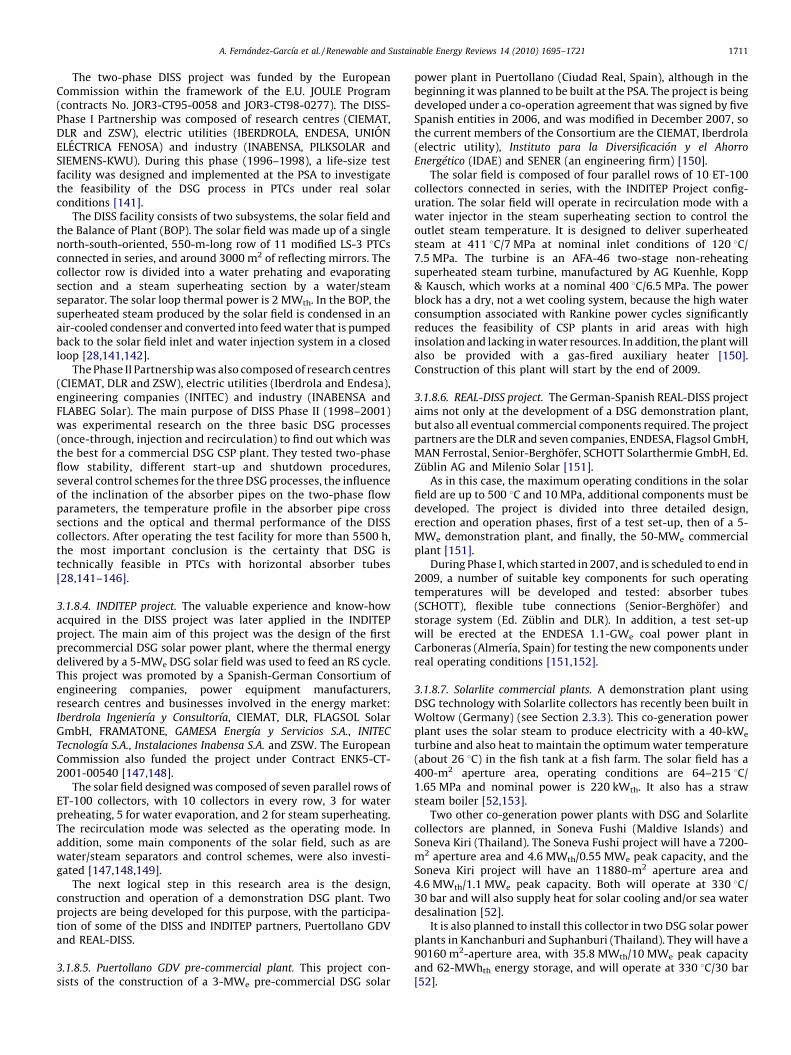
A. Fernandez-Garcıa et al. / Renewable and Sustainable Energy Reviews 14 (2010) 1695–1721 1711
The two-phase DISS project was funded by the EuropeanCommission within the framework of the E.U. JOULE Program(contracts No. JOR3-CT95-0058 and JOR3-CT98-0277). The DISS-Phase I Partnership was composed of research centres (CIEMAT,DLR and ZSW), electric utilities (IBERDROLA, ENDESA, UNIONELECTRICA FENOSA) and industry (INABENSA, PILKSOLAR andSIEMENS-KWU). During this phase (1996–1998), a life-size testfacility was designed and implemented at the PSA to investigatethe feasibility of the DSG process in PTCs under real solarconditions [141].
The DISS facility consists of two subsystems, the solar field andthe Balance of Plant (BOP). The solar field was made up of a singlenorth-south-oriented, 550-m-long row of 11 modified LS-3 PTCsconnected in series, and around 3000 m2 of reflecting mirrors. Thecollector row is divided into a water prehating and evaporatingsection and a steam superheating section by a water/steamseparator. The solar loop thermal power is 2 MWth. In the BOP, thesuperheated steam produced by the solar field is condensed in anair-cooled condenser and converted into feed water that is pumpedback to the solar field inlet and water injection system in a closedloop [28,141,142].
The Phase II Partnership was also composed of research centres(CIEMAT, DLR and ZSW), electric utilities (Iberdrola and Endesa),engineering companies (INITEC) and industry (INABENSA andFLABEG Solar). The main purpose of DISS Phase II (1998–2001)was experimental research on the three basic DSG processes(once-through, injection and recirculation) to find out which wasthe best for a commercial DSG CSP plant. They tested two-phaseflow stability, different start-up and shutdown procedures,several control schemes for the three DSG processes, the influenceof the inclination of the absorber pipes on the two-phase flowparameters, the temperature profile in the absorber pipe crosssections and the optical and thermal performance of the DISScollectors. After operating the test facility for more than 5500 h,the most important conclusion is the certainty that DSG istechnically feasible in PTCs with horizontal absorber tubes[28,141–146].
3.1.8.4. INDITEP project. The valuable experience and know-howacquired in the DISS project was later applied in the INDITEPproject. The main aim of this project was the design of the firstprecommercial DSG solar power plant, where the thermal energydelivered by a 5-MWe DSG solar field was used to feed an RS cycle.This project was promoted by a Spanish-German Consortium ofengineering companies, power equipment manufacturers,research centres and businesses involved in the energy market:Iberdrola Ingenierıa y Consultorıa, CIEMAT, DLR, FLAGSOL SolarGmbH, FRAMATONE, GAMESA Energıa y Servicios S.A., INITEC
Tecnologıa S.A., Instalaciones Inabensa S.A. and ZSW. The EuropeanCommission also funded the project under Contract ENK5-CT-2001-00540 [147,148].
The solar field designed was composed of seven parallel rows ofET-100 collectors, with 10 collectors in every row, 3 for waterpreheating, 5 for water evaporation, and 2 for steam superheating.The recirculation mode was selected as the operating mode. Inaddition, some main components of the solar field, such as arewater/steam separators and control schemes, were also investi-gated [147,148,149].
The next logical step in this research area is the design,construction and operation of a demonstration DSG plant. Twoprojects are being developed for this purpose, with the participa-tion of some of the DISS and INDITEP partners, Puertollano GDVand REAL-DISS.
3.1.8.5. Puertollano GDV pre-commercial plant. This project con-sists of the construction of a 3-MWe pre-commercial DSG solar
power plant in Puertollano (Ciudad Real, Spain), although in thebeginning it was planned to be built at the PSA. The project is beingdeveloped under a co-operation agreement that was signed by fiveSpanish entities in 2006, and was modified in December 2007, sothe current members of the Consortium are the CIEMAT, Iberdrola(electric utility), Instituto para la Diversificacion y el Ahorro
Energetico (IDAE) and SENER (an engineering firm) [150].The solar field is composed of four parallel rows of 10 ET-100
collectors connected in series, with the INDITEP Project config-uration. The solar field will operate in recirculation mode with awater injector in the steam superheating section to control theoutlet steam temperature. It is designed to deliver superheatedsteam at 411 8C/7 MPa at nominal inlet conditions of 120 8C/7.5 MPa. The turbine is an AFA-46 two-stage non-reheatingsuperheated steam turbine, manufactured by AG Kuenhle, Kopp& Kausch, which works at a nominal 400 8C/6.5 MPa. The powerblock has a dry, not a wet cooling system, because the high waterconsumption associated with Rankine power cycles significantlyreduces the feasibility of CSP plants in arid areas with highinsolation and lacking in water resources. In addition, the plant willalso be provided with a gas-fired auxiliary heater [150].Construction of this plant will start by the end of 2009.
3.1.8.6. REAL-DISS project. The German-Spanish REAL-DISS projectaims not only at the development of a DSG demonstration plant,but also all eventual commercial components required. The projectpartners are the DLR and seven companies, ENDESA, Flagsol GmbH,MAN Ferrostal, Senior-Berghofer, SCHOTT Solarthermie GmbH, Ed.Zublin AG and Milenio Solar [151].
As in this case, the maximum operating conditions in the solarfield are up to 500 8C and 10 MPa, additional components must bedeveloped. The project is divided into three detailed design,erection and operation phases, first of a test set-up, then of a 5-MWe demonstration plant, and finally, the 50-MWe commercialplant [151].
During Phase I, which started in 2007, and is scheduled to end in2009, a number of suitable key components for such operatingtemperatures will be developed and tested: absorber tubes(SCHOTT), flexible tube connections (Senior-Berghofer) andstorage system (Ed. Zublin and DLR). In addition, a test set-upwill be erected at the ENDESA 1.1-GWe coal power plant inCarboneras (Almerıa, Spain) for testing the new components underreal operating conditions [151,152].
3.1.8.7. Solarlite commercial plants. A demonstration plant usingDSG technology with Solarlite collectors has recently been built inWoltow (Germany) (see Section 2.3.3). This co-generation powerplant uses the solar steam to produce electricity with a 40-kWe
turbine and also heat to maintain the optimum water temperature(about 26 8C) in the fish tank at a fish farm. The solar field has a400-m2 aperture area, operating conditions are 64–215 8C/1.65 MPa and nominal power is 220 kWth. It also has a strawsteam boiler [52,153].
Two other co-generation power plants with DSG and Solarlitecollectors are planned, in Soneva Fushi (Maldive Islands) andSoneva Kiri (Thailand). The Soneva Fushi project will have a 7200-m2 aperture area and 4.6 MWth/0.55 MWe peak capacity, and theSoneva Kiri project will have an 11880-m2 aperture area and4.6 MWth/1.1 MWe peak capacity. Both will operate at 330 8C/30 bar and will also supply heat for solar cooling and/or sea waterdesalination [52].
It is also planned to install this collector in two DSG solar powerplants in Kanchanburi and Suphanburi (Thailand). They will have a90160 m2-aperture area, with 35.8 MWth/10 MWe peak capacityand 62-MWhth energy storage, and will operate at 330 8C/30 bar[52].
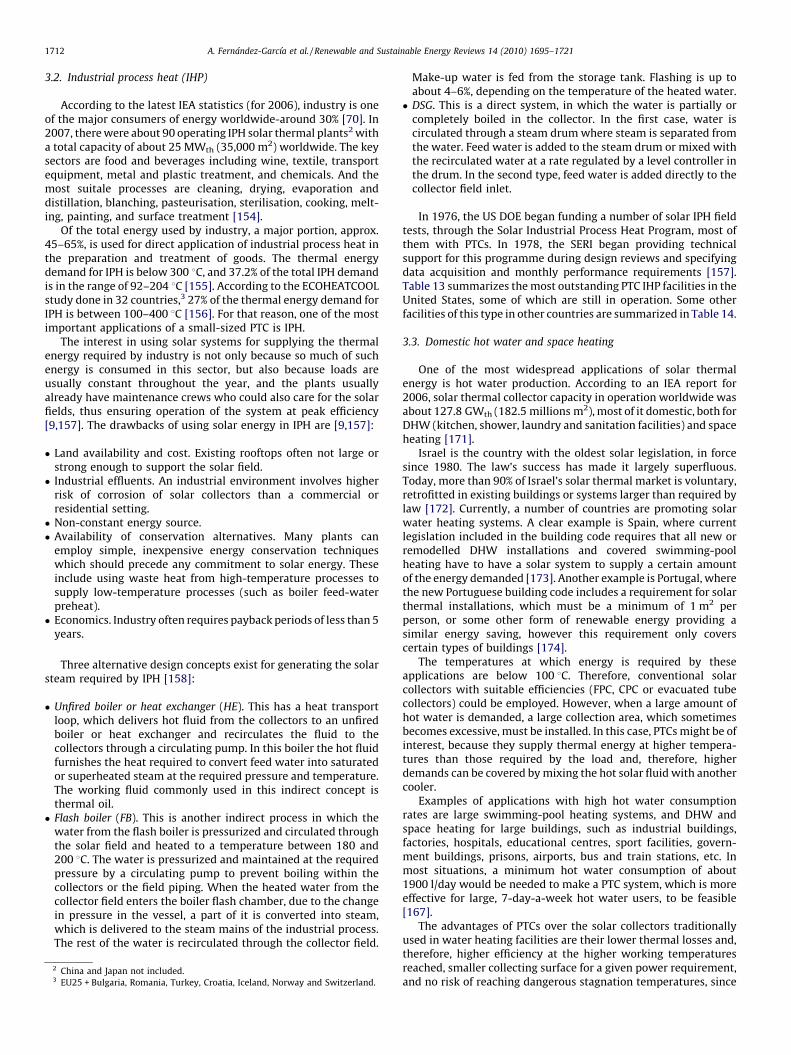
A. Fernandez-Garcıa et al. / Renewable and Sustainable Energy Reviews 14 (2010) 1695–17211712
3.2. Industrial process heat (IHP)
According to the latest IEA statistics (for 2006), industry is oneof the major consumers of energy worldwide-around 30% [70]. In2007, there were about 90 operating IPH solar thermal plants2 witha total capacity of about 25 MWth (35,000 m2) worldwide. The keysectors are food and beverages including wine, textile, transportequipment, metal and plastic treatment, and chemicals. And themost suitale processes are cleaning, drying, evaporation anddistillation, blanching, pasteurisation, sterilisation, cooking, melt-ing, painting, and surface treatment [154].
Of the total energy used by industry, a major portion, approx.45–65%, is used for direct application of industrial process heat inthe preparation and treatment of goods. The thermal energydemand for IPH is below 300 8C, and 37.2% of the total IPH demandis in the range of 92–204 8C [155]. According to the ECOHEATCOOLstudy done in 32 countries,3 27% of the thermal energy demand forIPH is between 100–400 8C [156]. For that reason, one of the mostimportant applications of a small-sized PTC is IPH.
The interest in using solar systems for supplying the thermalenergy required by industry is not only because so much of suchenergy is consumed in this sector, but also because loads areusually constant throughout the year, and the plants usuallyalready have maintenance crews who could also care for the solarfields, thus ensuring operation of the system at peak efficiency[9,157]. The drawbacks of using solar energy in IPH are [9,157]:
� Land availability and cost. Existing rooftops often not large orstrong enough to support the solar field.� Industrial effluents. An industrial environment involves higher
risk of corrosion of solar collectors than a commercial orresidential setting.� Non-constant energy source.� Availability of conservation alternatives. Many plants can
employ simple, inexpensive energy conservation techniqueswhich should precede any commitment to solar energy. Theseinclude using waste heat from high-temperature processes tosupply low-temperature processes (such as boiler feed-waterpreheat).� Economics. Industry often requires payback periods of less than 5
years.
Three alternative design concepts exist for generating the solarsteam required by IPH [158]:
� Unfired boiler or heat exchanger (HE). This has a heat transportloop, which delivers hot fluid from the collectors to an unfiredboiler or heat exchanger and recirculates the fluid to thecollectors through a circulating pump. In this boiler the hot fluidfurnishes the heat required to convert feed water into saturatedor superheated steam at the required pressure and temperature.The working fluid commonly used in this indirect concept isthermal oil.� Flash boiler (FB). This is another indirect process in which the
water from the flash boiler is pressurized and circulated throughthe solar field and heated to a temperature between 180 and200 8C. The water is pressurized and maintained at the requiredpressure by a circulating pump to prevent boiling within thecollectors or the field piping. When the heated water from thecollector field enters the boiler flash chamber, due to the changein pressure in the vessel, a part of it is converted into steam,which is delivered to the steam mains of the industrial process.The rest of the water is recirculated through the collector field.
2 China and Japan not included.3 EU25 + Bulgaria, Romania, Turkey, Croatia, Iceland, Norway and Switzerland.
Make-up water is fed from the storage tank. Flashing is up toabout 4–6%, depending on the temperature of the heated water.� DSG. This is a direct system, in which the water is partially or
completely boiled in the collector. In the first case, water iscirculated through a steam drum where steam is separated fromthe water. Feed water is added to the steam drum or mixed withthe recirculated water at a rate regulated by a level controller inthe drum. In the second type, feed water is added directly to thecollector field inlet.
In 1976, the US DOE began funding a number of solar IPH fieldtests, through the Solar Industrial Process Heat Program, most ofthem with PTCs. In 1978, the SERI began providing technicalsupport for this programme during design reviews and specifyingdata acquisition and monthly performance requirements [157].Table 13 summarizes the most outstanding PTC IHP facilities in theUnited States, some of which are still in operation. Some otherfacilities of this type in other countries are summarized in Table 14.
3.3. Domestic hot water and space heating
One of the most widespread applications of solar thermalenergy is hot water production. According to an IEA report for2006, solar thermal collector capacity in operation worldwide wasabout 127.8 GWth (182.5 millions m2), most of it domestic, both forDHW (kitchen, shower, laundry and sanitation facilities) and spaceheating [171].
Israel is the country with the oldest solar legislation, in forcesince 1980. The law’s success has made it largely superfluous.Today, more than 90% of Israel’s solar thermal market is voluntary,retrofitted in existing buildings or systems larger than required bylaw [172]. Currently, a number of countries are promoting solarwater heating systems. A clear example is Spain, where currentlegislation included in the building code requires that all new orremodelled DHW installations and covered swimming-poolheating have to have a solar system to supply a certain amountof the energy demanded [173]. Another example is Portugal, wherethe new Portuguese building code includes a requirement for solarthermal installations, which must be a minimum of 1 m2 perperson, or some other form of renewable energy providing asimilar energy saving, however this requirement only coverscertain types of buildings [174].
The temperatures at which energy is required by theseapplications are below 100 8C. Therefore, conventional solarcollectors with suitable efficiencies (FPC, CPC or evacuated tubecollectors) could be employed. However, when a large amount ofhot water is demanded, a large collection area, which sometimesbecomes excessive, must be installed. In this case, PTCs might be ofinterest, because they supply thermal energy at higher tempera-tures than those required by the load and, therefore, higherdemands can be covered by mixing the hot solar fluid with anothercooler.
Examples of applications with high hot water consumptionrates are large swimming-pool heating systems, and DHW andspace heating for large buildings, such as industrial buildings,factories, hospitals, educational centres, sport facilities, govern-ment buildings, prisons, airports, bus and train stations, etc. Inmost situations, a minimum hot water consumption of about1900 l/day would be needed to make a PTC system, which is moreeffective for large, 7-day-a-week hot water users, to be feasible[167].
The advantages of PTCs over the solar collectors traditionallyused in water heating facilities are their lower thermal losses and,therefore, higher efficiency at the higher working temperaturesreached, smaller collecting surface for a given power requirement,and no risk of reaching dangerous stagnation temperatures, since
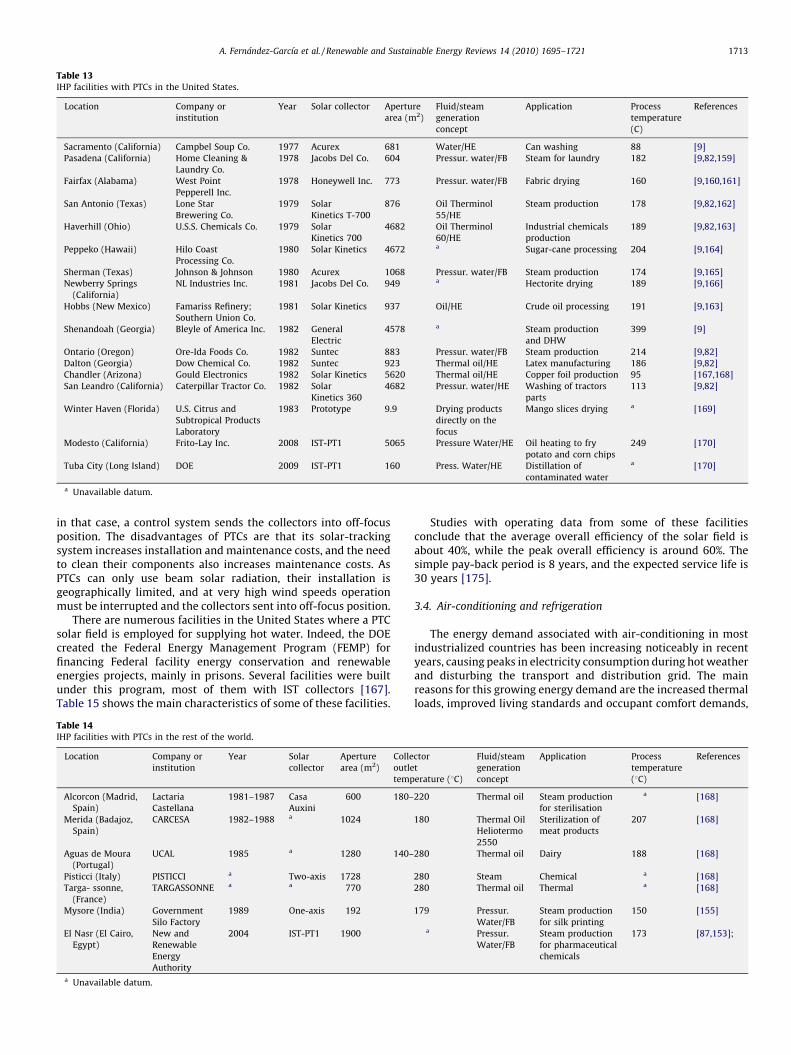
Table 13IHP facilities with PTCs in the United States.
Location Company or
institution
Year Solar collector Aperture
area (m2)
Fluid/steam
generation
concept
Application Process
temperature
(C)
References
Sacramento (California) Campbel Soup Co. 1977 Acurex 681 Water/HE Can washing 88 [9]
Pasadena (California) Home Cleaning &
Laundry Co.
1978 Jacobs Del Co. 604 Pressur. water/FB Steam for laundry 182 [9,82,159]
Fairfax (Alabama) West Point
Pepperell Inc.
1978 Honeywell Inc. 773 Pressur. water/FB Fabric drying 160 [9,160,161]
San Antonio (Texas) Lone Star
Brewering Co.
1979 Solar
Kinetics T-700
876 Oil Therminol
55/HE
Steam production 178 [9,82,162]
Haverhill (Ohio) U.S.S. Chemicals Co. 1979 Solar
Kinetics 700
4682 Oil Therminol
60/HE
Industrial chemicals
production
189 [9,82,163]
Peppeko (Hawaii) Hilo Coast
Processing Co.
1980 Solar Kinetics 4672 a Sugar-cane processing 204 [9,164]
Sherman (Texas) Johnson & Johnson 1980 Acurex 1068 Pressur. water/FB Steam production 174 [9,165]
Newberry Springs
(California)
NL Industries Inc. 1981 Jacobs Del Co. 949 a Hectorite drying 189 [9,166]
Hobbs (New Mexico) Famariss Refinery;
Southern Union Co.
1981 Solar Kinetics 937 Oil/HE Crude oil processing 191 [9,163]
Shenandoah (Georgia) Bleyle of America Inc. 1982 General
Electric
4578 a Steam production
and DHW
399 [9]
Ontario (Oregon) Ore-Ida Foods Co. 1982 Suntec 883 Pressur. water/FB Steam production 214 [9,82]
Dalton (Georgia) Dow Chemical Co. 1982 Suntec 923 Thermal oil/HE Latex manufacturing 186 [9,82]
Chandler (Arizona) Gould Electronics 1982 Solar Kinetics 5620 Thermal oil/HE Copper foil production 95 [167,168]
San Leandro (California) Caterpillar Tractor Co. 1982 Solar
Kinetics 360
4682 Pressur. water/HE Washing of tractors
parts
113 [9,82]
Winter Haven (Florida) U.S. Citrus and
Subtropical Products
Laboratory
1983 Prototype 9.9 Drying products
directly on the
focus
Mango slices drying a [169]
Modesto (California) Frito-Lay Inc. 2008 IST-PT1 5065 Pressure Water/HE Oil heating to fry
potato and corn chips
249 [170]
Tuba City (Long Island) DOE 2009 IST-PT1 160 Press. Water/HE Distillation of
contaminated water
a [170]
a Unavailable datum.
A. Fernandez-Garcıa et al. / Renewable and Sustainable Energy Reviews 14 (2010) 1695–1721 1713
in that case, a control system sends the collectors into off-focusposition. The disadvantages of PTCs are that its solar-trackingsystem increases installation and maintenance costs, and the needto clean their components also increases maintenance costs. AsPTCs can only use beam solar radiation, their installation isgeographically limited, and at very high wind speeds operationmust be interrupted and the collectors sent into off-focus position.
There are numerous facilities in the United States where a PTCsolar field is employed for supplying hot water. Indeed, the DOEcreated the Federal Energy Management Program (FEMP) forfinancing Federal facility energy conservation and renewableenergies projects, mainly in prisons. Several facilities were builtunder this program, most of them with IST collectors [167].Table 15 shows the main characteristics of some of these facilities.
Table 14IHP facilities with PTCs in the rest of the world.
Location Company or
institution
Year Solar
collector
Aperture
area (m2)
Colle
outle
temp
Alcorcon (Madrid,
Spain)
Lactaria
Castellana
1981–1987 Casa
Auxini
600 180–
Merida (Badajoz,
Spain)
CARCESA 1982–1988 a 1024
Aguas de Moura
(Portugal)
UCAL 1985 a 1280 140–
Pisticci (Italy) PISTICCI a Two-axis 1728
Targa- ssonne,
(France)
TARGASSONNE a a 770
Mysore (India) Government
Silo Factory
1989 One-axis 192
El Nasr (El Cairo,
Egypt)
New and
Renewable
Energy
Authority
2004 IST-PT1 1900
a Unavailable datum.
Studies with operating data from some of these facilitiesconclude that the average overall efficiency of the solar field isabout 40%, while the peak overall efficiency is around 60%. Thesimple pay-back period is 8 years, and the expected service life is30 years [175].
3.4. Air-conditioning and refrigeration
The energy demand associated with air-conditioning in mostindustrialized countries has been increasing noticeably in recentyears, causing peaks in electricity consumption during hot weatherand disturbing the transport and distribution grid. The mainreasons for this growing energy demand are the increased thermalloads, improved living standards and occupant comfort demands,
ctor
t
erature (8C)
Fluid/steam
generation
concept
Application Process
temperature
(8C)
References
220 Thermal oil Steam production
for sterilisation
a [168]
180 Thermal Oil
Heliotermo
2550
Sterilization of
meat products
207 [168]
280 Thermal oil Dairy 188 [168]
280 Steam Chemical a [168]
280 Thermal oil Thermal a [168]
179 Pressur.
Water/FB
Steam production
for silk printing
150 [155]
a Pressur.
Water/FB
Steam production
for pharmaceutical
chemicals
173 [87,153];
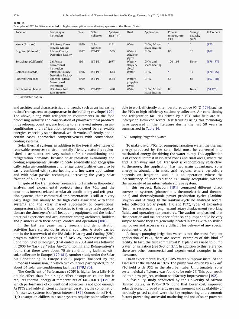
Table 15Examples of PTC facilities connected to high-consumption water-heating systems in the United States.
Location Company or
institution
Year Solar
collector
Aperture
area (m2)
Fluid Application Process
temperature
(8C)
Storage
capacity
(m3)
References
Yuma (Arizona) U.S. Army Yuma
Proving Ground
1979 Solar
Kinetics
1191 Water DHW, AC and
space heating
a a [175]
Brighton (Colorado) Adams County
Detention Facility
1987 IST-PT1 555 Water +
ethylene
glycol
DHW 85 19 [167]
Tehachapi (California) California
Correctional
Institution
1991 IST-PT1 2677 Water +
ethylene
glycol
DHW and
space heating
104–116 None [176,177]
Golden (Colorado) Jefferson County
Detention Facility
1996 IST-PT1 633 Water DHW a 17 [170,175]
Phoenix (Arizona) Phoenix Federal
Correctional
Institution
1999 IST-PT1 1584 Water +
propylen
glycol
DHW 55 87 [167,178]
San Antonio (Texas) U.S. Army Fort
Sam Houston
2003 IST-RMT 420 Water DHW, AC and
space heating
88 None [58,175]
a Unavailable datum.
A. Fernandez-Garcıa et al. / Renewable and Sustainable Energy Reviews 14 (2010) 1695–17211714
and architectural characteristics and trends, such as an increasingratio of transparent to opaque areas in the building envelope [179].The above, along with refrigeration requirements in the foodprocessing industry and conservation of pharmaceutical productsin developing countries, are leading to a renewed interest in air-conditioning and refrigeration systems powered by renewableenergies, especially solar thermal, which works efficiently, and incertain cases, approaches competitiveness with conventionalcooling systems.
Solar thermal systems, in addition to the typical advantages ofrenewable resources (environmentally-friendly, naturally replen-ished, distributed), are very suitable for air-conditioning andrefrigeration demands, because solar radiation availability andcooling requirements usually coincide seasonally and geographi-cally. Solar air-conditioning and refrigeration facilities can also beeasily combined with space heating and hot-water applicationsand with solar passive techniques, increasing the yearly solarfraction of buildings.
In spite of the tremendous research effort made in theoreticalanalysis and experimental projects since the 70s, and theenormous interest related to solar air-conditioning and refrigera-tion systems, their commercial implementation is still at a veryearly stage, due mainly to the high costs associated with thesesystems and the clear market supremacy of conventionalcompression chillers. Other obstacles to their large-scale applica-tion are the shortage of small heat pump equipment and the lack ofpractical experience and acquaintance among architects, buildersand planners with their design, control and operation [180].
In the last few years, many research and demonstrationactivities have started up in several countries. A study carriedout in the framework of the IEA Solar Heating and Cooling (SHC)program, within the activities of Task 25, ‘‘Solar-Assisted Air-Conditioning of Buildings’’, (that ended in 2004 and was followedin 2006 by Task 38 ‘‘Solar Air-Conditioning and Refrigeration’’),found that there were about 70 air-conditioning facilities withsolar collectors in Europe [179,181]. Another study under the SolarAir Conditioning in Europe (SACE) project, financed by theEuropean Commission, in which five countries participated, foundabout 54 solar air-conditioning facilities [179,180].
The Coefficient of Performance (COP) is higher for a LiBr–H2Odouble-effect than for a single-effect absorption chiller, but itrequires thermal energy at temperatures of 140–160 8C [179], atwhich performance of conventional collectors is not good enough.As PTCs are highly efficient at these temperatures, the combinationof these two systems is of great interest [182]. Connection of NH3–H2O absorption chillers to a solar system requires solar collectors
able to work efficiently at temperatures above 95 8C [179], such asthe PTCs or high-efficiency stationary collectors. Air-conditioningand refrigeration facilities driven by a PTC solar field are stillinfrequent. However, several test facilities using this technologyhave appeared in the literature during the last 50 years assummarized in Table 16.
3.5. Pumping irrigation water
To make use of PTCs for pumping irrigation water, the thermalenergy produced by the solar field must be converted intomechanical energy for driving the water pump. This applicationis of especial interest in isolated zones and rural areas, where thegrid is far away and fuel transport is economically restrictive.Furthermore, this application has two main advantages: solarenergy is abundant in most arid regions, where agriculturedepends on irrigation, and it is an operation where theintermittency of solar radiation is usually acceptable, withoutthe necessity of an intermediate storage system.
In this respect, Bahadori [191] compared different directconversion systems (photovoltaic, thermoelectric and thermo-ionic) and thermodynamic power production cycles (Rankine,Brayton and Stirling). In the Rankine-cycle he analyzed severalsolar collectors (solar ponds, FPC and PTC), types of expanders(turbines, reciprocating engines and rotary displacement), workingfluids, and operating temperatures. The author emphasized thatthe operation and maintenance of the solar pumps should be verysimple because they are generally located in areas with no skilledmanpower and access is very difficult for delivery of any specialequipment or parts.
Although pumping irrigation water is not the most frequentapplication of PTCs, there are several examples of this kind offacility. In fact, the first commercial PTC plant was used to pumpwater for irrigation (see Section 2.1). In addition to this reference,there are other commercial and experimental examples in theliterature.
On an experimental level, a 1-kW water pump was installed andassessed at the UNAM in 1976. The pump was driven by a 12-m2
PTC field with DSG in the absorber tube. Unfortunately, solarsystem global efficiency was found to be only 2%. This poor resultled to a new project, without satisfactory improvement [192].
A feasibility study conducted by the University of Arizona(United States) in 1975–1976 found that lower cost, improvedsolar devices, improved energy use management and availability ofmodestly priced capital were the key engineering and economicfactors preventing successful marketing and use of solar-powered

Table 16Some PTC facilities connected to solar cooling systems (absorption chillers).
Location Company or institution Year Solar
collector
Aperture
area (m2)
Collector
outlet
temperature (8C)
Fluid Application Process
temperature
(8C)
Chiller type/model/fluid
pairs/power (kW)
References
Montlouis (Pyrenees-
Orientales, France)
Laboratoire de l’Energie
Solaire
1957 Prototype 1.5 a NH3 Ice production (6 kg/day) 90 SEb/prototype/H2O-NH3/a [183]
Florida (USA) University of Florida 1957 Prototype 4.46 288 Cotton-seed oil ACc a SE/prototype/H2O-NH3/a [184]
Sulaibiya (Kuwait) Kuwait Institute for
Scientific Research
1984 Prototype 63.2 a Water AC 98.9 SE/ARKLA Solaire 501/
BrLi–H2O/10.55
[185]
Juzbado
(Salamanca, Spain)
Empresa Nacional de
Uranio (ENUSA)
1985 a 1080 180 Oil Heliotermo
2550
Cold generation a SE/a [168]
Kharagpur (India) Solar Energy Laboratory,
Indian Institute of Technology
1989 Prototype 1.5 a Water Food Preservation (3 8C) 92 SE/Himalux/a/0.25/ [186]
Amman (Jordan) University of Jordan 1991 Prototype 3.6 FPC
+0.15 PTC
a Water AC 95 SE/prototype/BrLi-H2O/a [187]
Madrid (Spain) Polytechnic University
of Madrid
2000 a a 150 Thermal oil Refrigeration in
isolated areas
a SE/prototype/H2O-NH3/2 [188]
Dalaman (Turkey) Iberotel Sarigerme Park 2004 Solitem
PTC-1800
360 180 Pressur. water Steam for AC and
Laundry
144 DEd/Broad/BrLi-H2O/116 [60,189]
Gebze (Turkey) Gebze Institute of
Technology
2006 Solitem
PTC-1800
360 180 Pressur. water AC and hot water
supply
144 DE/Broad/BrLi-H2O/260 [153,190]
Douglas (Arizona, USA) Chochise College Campus 2006 IST-PT1 634 a Pressur. water AC and space heating 121 SE/Energy Concepts/
H2O-NH3/210
[170]
Long Island (New
York, USA)
Steinway and Sons 2009 IST-PT1 533 200 Pressur. water AC, space heating
and steam production
a DE/Broad/BrLi-H2O/315 [170]
a Unavailable datum.b Single-effect.c Air-conditioning.d Double-effect.
Table 17Pumping irrigation water commercial plants with PTCs.
Location Company or
institution
Year Solar collector/
efficiency (%)
Aperture
area (m2)
Fluid Rankine cycle
efficiency (%)/
fluid/power (kW)
Process
temperature
(8C)
Irrigated field area
(ha)/flow (m3/min)/
depth (m)
Storage
capacity
(m3)
References
Phoenix
(Arizona, USA)
Gila River Ranch 1977 PTC/44-50 564 Water a/R113/37mechanic 149 a/38/3 None [2,193]
Willard
(New Mexico, USA)
Paragon Resources 1977–1978 Acurex + Solar
Kinetics/25
625 + 651 Oil Caloria
HT-43
15/R113/19mechanic 216 49/2.6/32 26 [2,82,194]
Coolidge
(Arizona, USA)
Dalton Cole Farm 1979 Acurex 3001/38.6 2140 Oil Caloria
HT-43
20/Toluene/200electric 288 80/a/100 189 [82,193]
a Unavailable datum.
A.
Ferna
nd
ez-Ga
rcıaet
al./R
enew
ab
lea
nd
Susta
ina
ble
En
ergy
Rev
iews
14
(20
10
)1
69
5–
17
21
17
15
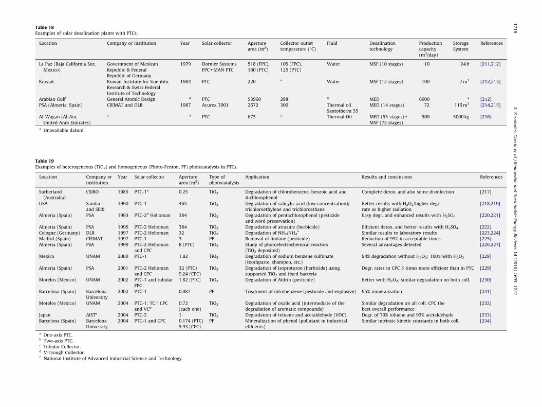
Table 19Examples of heterogeneous (TiO2) and homogeneous (Photo-Fenton, PF) photocatalysis in PTCs.
Location Company or
institution
Year Solar collector Aperture
area (m2)
Type of
photocatalysis
Application Results and conclusions References
Sutherland
(Australia)
CSIRO 1985 PTC-1a 0.25 TiO2 Degradation of chlorobenzene, benzoic acid and
4-chlorophenol
Complete detox. and also some disinfection [217]
USA Sandia
and SERI
1990 PTC-1 465 TiO2 Degradation of salicylic acid (low concentration)/
trichloroethylene and trichloroethane
Better results with H2O2/higher degr.
rate as higher radiation
[218,219]
Almeria (Spain) PSA 1993 PTC-2b Helioman 384 TiO2 Degradation of pentachlorophenol (pesticide
and word preservation)
Easy degr. and enhanced results with H2SO4 [220,221]
Almeria (Spain) PSA 1996 PTC-2 Helioman 384 TiO2 Degradation of atrazine (herbicide) Efficient detox. and better results with H2SO4 [222]
Cologne (Germany) DLR 1997 PTC-2 Helioman 32 TiO2 Degradation of NH3/NH4+ Similar results to laboratory results [223,224]
Madrid (Spain) CIEMAT 1997 PTC-1 3 PF Removal of lindane (pesticide) Reduction of 99% in acceptable times [225]
Almeria (Spain) PSA 1999 PTC-2 Helioman
and CPC
8 (PTC) TiO2 Study of photoelectrochemical reactors
(TiO2 deposited)
Several advantages detected [226,227]
Mexico UNAM 2000 PTC-1 1.82 TiO2 Degradation of sodium benzene sulfonate
(toothpaste, shampoo, etc.)
94% degradation without H2O2; 100% with H2O2 [228]
Almeria (Spain) PSA 2001 PTC-2 Helioman
and CPC
32 (PTC)
9.24 (CPC)
TiO2 Degradation of isoproturon (herbicide) using
supported TiO2 and fixed bacteria
Degr. rates in CPC 5 times more efficient than in PTC [229]
Morelos (Mexico) UNAM 2002 PTC-1 and tubular
FPC
1.82 (PTC) TiO2 Degradation of Aldrin (pesticide) Better with H2O2; similar degradation on both coll. [230]
Barcelona (Spain) Barcelona
University
2002 PTC-1 0.087 PF Treatment of nitrobenzene (pesticide and explosive) 95% mineralization [231]
Morelos (Mexico) UNAM 2004 PTC-1; TC;c CPC
and VCd
0.72
(each one)
TiO2 Degradation of oxalic acid (intermediate of the
degradation of aromatic compounds)
Similar degradation on all coll. CPC the
best overall performance
[232]
Japan AISTe 2004 PTC-2 1 TiO2 Degradation of toluene and acetaldehyde (VOC) Degr. of 79% toluene and 93% acetaldehyde [233]
Barcelona (Spain) Barcelona
University
2004 PTC-1 and CPC 0.174 (PTC)
5.93 (CPC)
PF Mineralization of phenol (pollutant in industrial
effluents)
Similar intrinsic kinetic constants in both coll. [234]
a One-axis PTC.b Two-axis PTC.c Tubular Collector.d V-Trough Collector.e National Institute of Advanced Industrial Science and Technology.
Table 18Examples of solar desalination plants with PTCs.
Location Company or institution Year Solar collector Aperture
area (m2)
Collector outlet
temperature (8C)
Fluid Desalination
technology
Production
capacity
(m3/day)
Storage
System
References
La Paz (Baja California Sur,
Mexico)
Government of Mexican
Republic & Federal
Republic of Germany
1979 Dornier Systems
FPC + MAN PTC
518 (FPC),
160 (PTC)
105 (FPC),
125 (PTC)
Water MSF (10 stages) 10 24 h [211,212]
Kuwait Kuwait Institute for Scientific
Research & Swiss Federal
Institute of Technology
1984 PTC 220 a Water MSF (12 stages) 100 7 m3 [212,213]
Arabian Gulf General Atomic Design a PTC 53960 288 a MED 6000 a [212]
PSA (Almeria, Spain) CIEMAT and DLR 1987 Acurex 3001 2672 300 Thermal oil
Santotherm 55
MED (14 stages) 72 115 m3 [214,215]
Al-Wagan (Al-Ain,
United Arab Emirates)
a a PTC 675 a Thermal Oil MED (55 stages) +
MSF (75 stages)
500 5000 kg [216]
a Unavailable datum.
A.
Ferna
nd
ez-Ga
rcıaet
al./R
enew
ab
lea
nd
Susta
ina
ble
En
ergy
Rev
iews
14
(20
10
)1
69
5–
17
21
17
16
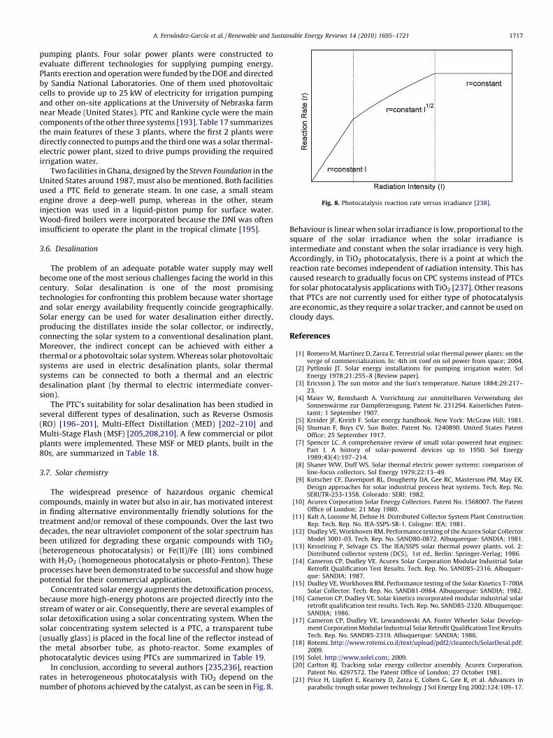
Fig. 8. Photocatalysis reaction rate versus irradiance [238].
A. Fernandez-Garcıa et al. / Renewable and Sustainable Energy Reviews 14 (2010) 1695–1721 1717
pumping plants. Four solar power plants were constructed toevaluate different technologies for supplying pumping energy.Plants erection and operation were funded by the DOE and directedby Sandia National Laboratories. One of them used photovoltaiccells to provide up to 25 kW of electricity for irrigation pumpingand other on-site applications at the University of Nebraska farmnear Meade (United States). PTC and Rankine cycle were the maincomponents of the other three systems [193]. Table 17 summarizesthe main features of these 3 plants, where the first 2 plants weredirectly connected to pumps and the third one was a solar thermal-electric power plant, sized to drive pumps providing the requiredirrigation water.
Two facilities in Ghana, designed by the Steven Foundation in theUnited States around 1987, must also be mentioned. Both facilitiesused a PTC field to generate steam. In one case, a small steamengine drove a deep-well pump, whereas in the other, steaminjection was used in a liquid-piston pump for surface water.Wood-fired boilers were incorporated because the DNI was ofteninsufficient to operate the plant in the tropical climate [195].
3.6. Desalination
The problem of an adequate potable water supply may wellbecome one of the most serious challenges facing the world in thiscentury. Solar desalination is one of the most promisingtechnologies for confronting this problem because water shortageand solar energy availability frequently coincide geographically.Solar energy can be used for water desalination either directly,producing the distillates inside the solar collector, or indirectly,connecting the solar system to a conventional desalination plant.Moreover, the indirect concept can be achieved with either athermal or a photovoltaic solar system. Whereas solar photovoltaicsystems are used in electric desalination plants, solar thermalsystems can be connected to both a thermal and an electricdesalination plant (by thermal to electric intermediate conver-sion).
The PTC’s suitability for solar desalination has been studied inseveral different types of desalination, such as Reverse Osmosis(RO) [196–201], Multi-Effect Distillation (MED) [202–210] andMulti-Stage Flash (MSF) [205,208,210]. A few commercial or pilotplants were implemented. These MSF or MED plants, built in the80s, are summarized in Table 18.
3.7. Solar chemistry
The widespread presence of hazardous organic chemicalcompounds, mainly in water but also in air, has motivated interestin finding alternative environmentally friendly solutions for thetreatment and/or removal of these compounds. Over the last twodecades, the near ultraviolet component of the solar spectrum hasbeen utilized for degrading these organic compounds with TiO2
(heterogeneous photocatalysis) or Fe(II)/Fe (III) ions combinedwith H2O2 (homogeneous photocatalysis or photo-Fenton). Theseprocesses have been demonstrated to be successful and show hugepotential for their commercial application.
Concentrated solar energy augments the detoxification process,because more high-energy photons are projected directly into thestream of water or air. Consequently, there are several examples ofsolar detoxification using a solar concentrating system. When thesolar concentrating system selected is a PTC, a transparent tube(usually glass) is placed in the focal line of the reflector instead ofthe metal absorber tube, as photo-reactor. Some examples ofphotocatalytic devices using PTCs are summarized in Table 19.
In conclusion, according to several authors [235,236], reactionrates in heterogeneous photocatalysis with TiO2 depend on thenumber of photons achieved by the catalyst, as can be seen in Fig. 8.
Behaviour is linear when solar irradiance is low, proportional to thesquare of the solar irradiance when the solar irradiance isintermediate and constant when the solar irradiance is very high.Accordingly, in TiO2 photocatalysis, there is a point at which thereaction rate becomes independent of radiation intensity. This hascaused research to gradually focus on CPC systems instead of PTCsfor solar photocatalysis applications with TiO2 [237]. Other reasonsthat PTCs are not currently used for either type of photocatalysisare economic, as they require a solar tracker, and cannot be used oncloudy days.
References
[1] Romero M, Martınez D, Zarza E. Terrestrial solar thermal power plants: on theverge of commercialization. In: 4th int conf on sol power from space; 2004.
[2] Pytlinski JT. Solar energy installations for pumping irrigation water. SolEnergy 1978;21:255–8 [Review paper].
[3] Ericsson J. The sun motor and the Sun’s temperature. Nature 1884;29:217–23.
[4] Maier W, Remshardt A. Vorrichtung zur unmittelbaren Verwendung derSonnenwarme zur Dampferzeugung. Patent Nr. 231294. Kaiserliches Paten-tamt; 1 September 1907.
[5] Kreider JF, Kreith F. Solar energy handbook. New York: McGraw Hill; 1981.[6] Shuman F, Boys CV. Sun Boiler. Patent No. 1240890. United States Patent
Office; 25 September 1917.[7] Spencer LC. A comprehensive review of small solar-powered heat engines:
Part I. A history of solar-powered devices up to 1950. Sol Energy1989;43(4):197–214.
[8] Shaner WW, Duff WS. Solar thermal electric power systems: comparison ofline-focus collectors. Sol Energy 1979;22:13–49.
[9] Kutscher CF, Davenport RL, Dougherty DA, Gee RC, Masterson PM, May EK.Design approaches for solar industrial process heat systems. Tech. Rep. No.SERI/TR-253-1358. Colorado: SERI; 1982.
[10] Acurex Corporation Solar Energy Collectors. Patent No. 1568007. The PatentOffice of London; 21 May 1980.
[11] Kalt A, Loosme M, Dehne H. Distributed Collector System Plant ConstructionRep. Tech. Rep. No. IEA-SSPS-SR-1. Cologne: IEA; 1981.
[12] Dudley VE, Workhoven RM. Performance testing of the Acurex Solar CollectorModel 3001-03. Tech. Rep. No. SAND80-0872. Albuquerque: SANDIA; 1981.
[13] Kesselring P, Selvage CS. The IEA/SSPS solar thermal power plants. vol. 2:Distributed collector system (DCS), 1st ed., Berlin: Springer-Verlag; 1986.
[14] Cameron CP, Dudley VE. Acurex Solar Corporation Modular Industrial SolarRetrofit Qualification Test Results. Tech. Rep. No. SAND85-2316. Albuquer-que: SANDIA; 1987.
[15] Dudley VE, Workhoven RM. Performance testing of the Solar Kinetics T-700ASolar Collector. Tech. Rep. No. SAND81-0984. Albuquerque: SANDIA; 1982.
[16] Cameron CP, Dudley VE. Solar kinetics incorporated modular industrial solarretrofit qualification test results. Tech. Rep. No. SAND85-2320. Albuquerque:SANDIA; 1986.
[17] Cameron CP, Dudley VE, Lewandowski AA. Foster Wheeler Solar Develop-ment Corporation Modular Industrial Solar Retrofit Qualification Test Results.Tech. Rep. No. SAND85-2319. Albuquerque: SANDIA; 1986.
[18] Rotemi. http://www.rotemi.co.il/text/upload/pdf2/cleantech/SolarDesal.pdf;2009.
[19] Solel. http://www.solel.com; 2009.[20] Carlton RJ. Tracking solar energy collector assembly. Acurex Corporation.
Patent No. 4297572. The Patent Office of London; 27 October 1981.[21] Price H, Lupfert E, Kearney D, Zarza E, Cohen G, Gee R, et al. Advances in
parabolic trough solar power technology. J Sol Energy Eng 2002;124:109–17.
A. Fernandez-Garcıa et al. / Renewable and Sustainable Energy Reviews 14 (2010) 1695–17211718
[22] Winter CJ, Sizman R, Vant-Hull L. Solar power plants—fundamentals, tech-nology systems and economics. Berlin: Springer-Verlag; 1991.
[23] DeMeo EA, Galdo JF. Renewable energy technology characterizations. Tech.Rep. No. NREL/TR-109496. Golden: NREL; 1997.
[24] Pharabod F, Philibert C. Luz solar power plants. Success in California andworldwide prospects. Tech. Rep. DLR for IEA-SSPS. SolarPACES; 1991.
[25] Dudley VE, Kolb GJ, Sloan M, Kearney D. Test results: SEGS LS-2 solarcollector. Tech. Rep. No. SAND94-1884. Albuquerque: SANDIA; 1994.
[26] Nava P, Aringhoff R, Svoboda P, Kearney D. Status rep on solar trough powerplants. Tech. Rep. Cologne: Pilkington; 1996.
[27] Mills D. Advances in solar thermal electricity technology. Sol Energy2004;76:13–9.
[28] Zarza E. Generacion directa de vapor con Colectores solares cilindro para-bolicos, proyecto Direct Solar Steam (DISS). Madrid: CIEMAT; 2004.
[29] Geyer M, Lupfert E, Osuna R, Esteban A, Schiel W, Schweitzer A, et al.EUROTROUGH—Parabolic trough collector developed for cost efficient solarpower generation. SolarPACES 2002. In: 11th int symp on conc sol power andchem energy technol; 2002.
[30] Lupfert E, Zarza-Moya E, Sichel W, Osuna-Gonzalez T, Esteban-Garmendia A,Geyer M, et al. Eurotrough collector qualification complete-performance testresults from PSA. In: ISES solar world congr; 2003.
[31] Dros A. Saint-Gobain solar: the supplier for solar mirrors CSP today. In: 2ndconc sol therm power summit; 2008.
[32] Ubach J. Today’s mirrors: a manufacture point of view Rioglass. In: 1st worldsol power conf; 2007.
[33] Ubach J, Miranda F, Castanon C, Ainz F, Martınez J, Lafarga N, et al. More light inthe desert: rioglass solar, a new parabolic trough mirror manufacturing facil-ities Lessons from the automotive glass process methodology. In: SolarPACES2008, 14th int symp on conc sol power and chem energy technol; 2008.
[34] Benz N, Kuckelkorn T. A new receiver for parabolic trough collectors. In:SolarPACES 2004, 12th int symp on conc sol power and chem energy technol;2004.
[35] Benz N. Receivers for parabolic trough schott. In: 1st world sol power conf;2007.
[36] Mandelberg E. Today trough receiver. Solel. In: 1st world sol power conf;2007.
[37] Kleinerman K. The solar field solution. Solel. In: CSP today, 2nd conc sol thermpower summit; 2008.
[38] Sola LA. Avances en tecnologıa de receptores para colectores parabolicos. In:CSP today, 2nd conc sol therm power summit; 2008.
[39] Benz N, Graf W, Hacker Z, Hildebrandt Ch, Mollenhoff M, Schulte-FischedickJ, et al. Advances in receiver technology for parabolic troughs. In: Solar-PACES 2008, 14th int symp on conc sol power and chem energy technol;2008.
[40] Herrmann U, Worringer S, Graeter F, Nava P. Three years of operationexperience of the SKAL-ET collector loop at SEGS. V. In: SolarPACES 2006,13th int symp on conc sol power and chem energy technol; 2006.
[41] Herrmann U, Nava P. Performance of the SKAL-ET collectors of the Andasolpower plants. In: SolarPACES 2008, 14th int symp on conc sol power andchem energy technol; 2008.
[42] Schiel W, Schweitzer A, Kracht O, Hunt B. Collector development for para-bolic trough power plants at Schlaich Bergermann und Partner. In: Solar-PACES 2006, 13th int symp on conc sol power and chem energy technol;2006.
[43] Gee RC, Hale MJ. Solargenix energy advanced parabolic trough development.NREL/CP-550-39206. In: 2005 DOE sol energy tech conference; 2005.
[44] Jones J. Concentrating solar power, CSP lifts off, 2007. Renew Energy World2007;10(3):36–8.
[45] Kearney DW. Parabolic trough collector overview. In: Parabolic trough work-shop 2007 at the NREL; 2007.
[46] Castaneda N, Vazquez J, Domingo M, Fernandez A, Leon J. Sener parabolictrough collector design and testing. In: SolarPACES 2006, 13th int symp onconc sol power and chem energy technol; 2006.
[47] Vazquez J, Castaneda N. Senertrough. The collector for Extresol-1. 600 metersloop test in Andasol-1 and test unit description. In: SolarPACES 2008, 14th intsymp on conc sol power and chem energy technol; 2008.
[48] Relloso S, Castaneda N, Domingo M. New Senertough collector developmentin collaboration with key components suppliers. In: SolarPACES 2008, 14thint symp on conc sol power and chem energy technol; 2008.
[49] Ozaez E. Almacenamiento termico: mejora de eficiencia. Albiasa solar. In: CSPtoday, 2nd conc sol therm power summit; 2008.
[50] Albiasa. http://www.albiasasolar.com; 2009[51] ENEA. http://www.enea.it; 2009[52] Solarlite. http://www.solarlite.de; 2009.[53] Ven JF. TOSCA: How a fusion of proven technologies leads to the new
generation parabolic trough. In: CSP today, 2nd conc sol therm powersummit; 2008.
[54] Marcotte P. Development of the focal point power trough (FPPT) & PT-2advanced concentrators for power generation. In: DOE sol energy technolprogram rev meet and peer rev; 2007.
[55] Price H. CSp trough systems; Abengoa Solar. In: DOE sol annu rev meet; 2008.[56] Leitner A. The sunrise of solar power. Concentrating solar power—what can
solar thermal electricity deliver, and at what price?; 26 June 2008, http://www.RenewableEnergyWorld.com.
[57] Kimura D. High efficiency power generation using low temperature water. In:CSP today, 2nd conc sol therm power summit; 2008.
[58] IST (Industrial Solar Technology Corporation). http://www.industrialsolartech.com; 2009.
[59] Dudley VE, Evans LR, Matthews CW. Test results: industrial solar technologyparabolic trough solar collector. Tech. Rep. No. SAND94-1117. Albuquerque:SANDIA; 1995.
[60] Lokurlu A, Richarts F, Kruger D. High efficient utilisation of solar energy withnewly developed parabolic trough collectors (SOLITEM PTC) for chilling andsteam production in a hotel at the Mediterranean coast of Turkey. Int J TechPolicy 2005;3(1/2):137–210.
[61] Weiss W, Rommel M. Process heat collectors. State of the art within task 33/IV. IEA SHC-Task 33 and SolarPACES-Task IV. Gleisdorf: AEE INTEC; 2008.
[62] Solitem. http://www.solitem.com.tr; 2009.[63] Millioud A, Dreyer J. Novel parabolic trough collector for roof mounted solar
cooling applications. In: EUROSUN 1008, 1st int congr on heating, cooling andbuildings; 2008.
[64] NEP solar. http://www.nep-solar.com; 2008.[65] SHAP (Solar Heat and Power). http://www.shap.it; 2009.[66] Linuo-Paradigma. http://en.linuo-pradigma.com/vacuum_tube.aspx; 2009.[67] Hoffschmidt B, Schwarzaer K, Spate F, Kotter J, Ebert M, Sierck O. Develop-
ment of a small modular parabolic trough collector. In: SolarPACES 2006,13th int symp on conc sol power and chem energy technol; 2006.
[68] Schwarzer K, Kroker J, Rusack M. Technical improvement of a small modularparabolic trough collector. In: EUROSUN 1008, 1st int congr on heating,cooling and buildings; 2008.p. 2008.
[69] Ramos C, Ramırez R, Huacuz J. Parablic trough development in Mexico.SolarPACES 2006. In: 13th int symp on conc sol power and chem energytechnol; 2006.
[70] Key world energy statistics. Tech. Rep. Paris: IEA; 2008.[71] Brakmann G, Aringhoff R, Geyer M, Teske S. Concentrated solar thermal
power-now!. Tech. Rep. Greenpeace, Amsterdam: ESTIA and SolarPACES;2005.
[72] Muller-Steinhagen H, Trieb F. Concentrating solar power: a review of thetechnology. Ingenia 2004;43–8.
[73] Marquez C. An overview of CSP in Europe, North Africa and the Middel East.Tech. Rep. CSP Today; 2008.
[74] Price H, Kearney D. Reducing the cost of energy from parabolic trough solarpower plants. Tech. Rep. No. NREL/CP-550-33208. Golden: NREL; 2003.
[75] Geyer M. Introducing concentrated solar power on the international market-worldwide incentives, policies and benefits. In: SolarPACES 2008, 14th intsymp on conc sol power and chem energy technol; 2008.
[76] Price H, Kearney D. Parabolic-trough technology roadmap: a pathway forsustained commercial development and deployment of parabolic-troughtechnology. Tech. Rep. No. NREL/TP-550-24748. Golden: NREL; 1999.
[77] Dersch J, Geyer M, Herrmann U, Jones SA, Kelly B, Kistner R, et al. Troughintegration into power plants—a study on the performance and economyof integrated solar combined cycle systems. Energy 2004;29:947–1013.
[78] Price HW. Parabolic trough solar power for competitive U.S. markets. NREL/CP-550-25798. In: ASME renew and adv energy syst for the 21st century conf;1999.
[79] NREL. http://www.nrel.gov/csp/troughnet/power_plant_data.html; 2009.[80] Cohen GE, Kearney DW, Kolb GJ. Final rep on the operation and mantenance
improvement program for concentratin solar power plants. Techn. Rep. No.SAND99-1290. California: SANDIA; 1999.
[81] Schraub FA, Dehne H. Electric generation system design: management,startup, and operation of IEA Distributed Collector Solar system in Almerıa,Spain. Sol Energy 1983;3(4):351–5.
[82] Solar Thermal Technology. Annual technical Progress Rep FY 1981. Volume II:Technical. Tech. Rep. No. DOE/JPL-1060-53. Pasadena: Jet Propulsion Labora-tory for the DOE; 1982.
[83] Kesselring P, Selvage CS. The IEA/SSPS solar thermal power plants. vol. 2:Distributed collector system (DCS). Berlin: Springer-Verlag; 1986.
[84] DSIRE (Database of State Incentives for Renewable Energy (USA)). http://www.dsireusa.org; 2009.
[85] Canada S, Cable R, Price H. Status of APS 1-MWe parabolic trough project. In:Conf. Paper No. NREL/CP-550-39205, 2005 DOE sol energy tech conf; 2005.
[86] Cohen G. Nevada Solar One First CSP operating solar energy power plant inNevada. In: World sol power conf; 2007.
[87] Solarpaces. http://www.solarpaces.org; 2009.[88] Taggart S. Parabolic troughs: CSP’s quiet achiever. Renew Energy Focus;
March/April 2008.[89] Solanasolar. http://www.solanasolar.com; 2009.[90] BrightSource. http://www.brightsourcenergy.com; 2009.[91] Schild P. Concentrated solar thermal in European communities
research framework programmes: achievement and challenges. In: Solar-PACES 2004, 12th int symp on conc sol power and chem energy technol;2004.
[92] White paper for a community strategy and action plan in the field of renew-able energy resources. COM97 (599) Final; 1997.
[93] European Directive 2001/77/CE of the European Parliament and of theCouncil of 27 September 2001, published on the Official Journal of theEuropean Communities number L283/33 on 27 October 2001, on the promo-tion of electricity produced from renewable energies sources in the internalelectricity market. Brussels; 2001.
[94] Plan de Fomento de las Energıas Renovables en Espana. Madrid; 1999.[95] Plan de Energıas Renovables en Espana, 2005–2010. Madrid; 2005.
A. Fernandez-Garcıa et al. / Renewable and Sustainable Energy Reviews 14 (2010) 1695–1721 1719
[96] Hernandez Gonzalvez C, Fresneda Garcıa A, Ruiz Castellano J. Solar thermo-electric area in the Spanish Renewable Energy Plan. In: SolarPACES 2006,13th int symp on conc sol power and chem energy technol; 2006.
[97] Ley 54/1997 de 27 de noviembre de 1997, del Sector Electrico, publicada enBOE numero 285 de 28 de noviembre de 1997. Madrid; 1997.
[98] Real Decreto 2818/1998 de 23 de diciembre de 1998, publicado en BOEnumero 312 de 30 de diciembre, sobre produccion de energıa electrica porinstalaciones abastecidas por recursos o fuentes de energıa renovables,residuos y cogeneracion. Madrid; 1998.
[99] Real Decreto 841/2002 de 2 de Agosto de 2002, publicado en BOE numero 210de 2 de septiembre de 2002, por el que se regula para las instalaciones deproduccion de energıa electrica en regimen especial. Madrid; 2002.
[100] Real Decreto 436/2004 del 12 de marzo de 2004, publicado en BOE numero75 de 27 de marzo de 2004, por el que se establece la metodologıa para laactuacion y sistematizacion del regimen jurıdico y economico de la actividadde produccion de energıa electrica en regimen especial. Madrid; 2004.
[101] Real Decreto 661/2007 de 25 de mayo de 2007, publicado en BOE numero 126de 26 de mayo 2007, por el que se regula la actividad de produccion deenergıa electrica en regimen especial. Madrid; 2007.
[102] Wittmann M, Eck M, Hirsch T, Pitz-Paal R. Theoretical economic potential ofthe Spanish premium tariff for solar thermal power plants. In: SolarPACES2008, 14th int symp on conc sol power and chem energy technol; 2008.
[103] Protermosolar. http://www.protermosolar.org; 2009.[104] Kistner R, Grehte K, Geyer M, Gladen H, Nebrera JA. The progress of the
AndaSol projects in Spain. In: SolarPACES 2004, 12th int symp on conc solpower and chem energy technol; 2004.
[105] Geyer M, Herrmann U, Sevilla A, Nebrera JA, Gomez Zamorza A. Dispatchablesolar electricity for sumerrly peak loads from the solar termal projectsAndasol-1 and Andasol-2. In: SolarPACES 2006, 13th int symp on conc solpower and chem energy technol; 2006.
[106] Hernandez Gonzalvez C, Martinez Palacio A, Caballero Ocana S, HerederoBueno C. Iberdrola renewables and solar thermal technologies. In: Solar-PACES 2008, 14th int symp on conc sol power and chem energy technol;2008.
[107] Osuna R, Fernandez-Quero V, Sanchez M. Plataforma Solar Sanlucar la Mayor:the largest European solar power site. In: SolarPACES 2008, 14th int symp onconc sol power and chem energy technol; 2008.
[108] Prieto C, Osuna R, Geyer M, Sanchez M, Fernandez-Quero V. Parabolic troughtechnology in Abengoa Solar. In: SolarPACES 2008, 14th int symp on conc solpower and chem energy technol; 2008.
[109] Gonzalez A, Liberali R. Concentrated solar power. From research to imple-mentation. Belgium: Office for Official Publications of the European Com-munities; 2007.
[110] Decree of Ministry of Economical Development 11/4/2008, Gazzetta ufficiale30/04/2008. Ministero dello Svilupp Economico-Criteri e modalita per incen-tivare la produzione di energia elettrica da fonte solare mediante ciclitermodinamici. Rome; 2008.
[111] Law 246/2006 of Genereation of Electricity using Renewable energy Sourcesand High-Efficciency Cogenereation of Electricity and Heat and Miscella-neaous Provisions. Published on the Official Gazette a’129 of 27 June 2006.Athenes; 2007.
[112] Flagsol. http://www.flagsol.com; 2009.[113] Decreto-Lei n8 225/2007 de 31 de Maio, concretiza um conjunto de medidas
ligadas as energias renovaveis previstas na estrategia nacional para a energia.Ministerio da Economia e da Inovacao. Diario da Republica, 1a Serie n8 105 31de Maio de 2007. Lisbon; 2007.
[114] Geyer M. Rep on the SolarPACES START mission to Algeria. IEA; 2003.[115] Algerienne Decret Executif No. 04-92 du 4 Safar 1425 correspondant au 25
mars 2004 relatif aux couts de diversification de la production d’electricite.Journal Officiel de la Republique Algerienne Democratique et Populaire, no.19, correspondant au 28 Mars 2004. Alger; 2004.
[116] Eichhammer W, Ragwitz M, Morin G, Lerchenmuller H, Stein W, Szewczuk S.Assessment of the world bank/global environment facility strategy for themarket development of concentrated solar thermal power. Rep No. GEF/C.25/Inf.11; 2005.
[117] Brakmann G, Berrehili M, Filali K. ISCC ain Beni mathar, integrated solarcombined cycle power plant in Morocco. In: SolarPACES 2006, 13th int sympon conc sol power and chem energy technol; 2006.
[118] Horn M, Fuhring H, Rheinlander J. Economic analysis of integrated solarcombined cycle power plants. A sample case: The economic feasibility of anISCCS power plant in Egypt. Energy 2004;29:935–1011.
[119] Geyer M. Report on the SolarPACES START Mission to Egypt. IEA; 1996.[120] Brakmann G, Fekry K, Fayek AM. ISCC Kuraymat. Integrated Solar Combined
Cycle Power Plant in Egypt. In: SolarPACES 2006, 13th Int Symp on Conc SolPower and Chem Energy Technol; 2006.
[121] MNI (Minister of National Infrastructures of Israel). http://www.mni.gov.il/mni/en-US/Energy/Messages/SpokesmanRenewableEnergy.htm; 2009.
[122] Hosseini R, Soltani M, Valizadeh G. Technical and economic assessment of theintegrated solar combined sycle power plants in Iran. Renew Energy2005;30:1541–615.
[123] YSTPP. http://www.ystpp.com; 2009.[124] Masdar. http://www.masdar.ae; 2009.[125] Cordeiro P. Rep on the SolarPACES START mission to Brazil. IEA; 1997.[126] Murphy LM, May EK. Steam generation in line-focus solar collectors: a
comparative assessment of thermal performance, operation and stabilityand cost issues. Tech. Rep. No. SERI/TR-632-1311. Golden: SERI; 1982.
[127] Pederson RJ, May EK. Flow instability during direct steam generation in aline-focus solar-collector system. Tech. Rep. No. SERI/TR-632-1354. Golden:SERI; 1982.
[128] Taitel Y, Dukler AD. A model for predicting flow regime transition in hor-izontal and near horizontal gas-liquid flow. AIChE J 1976;22(1):47–9.
[129] Barnea DA. A unified model for predicting flow-pattern transitions for thewhole range of pipe inclinations. Int J Multiphase Flow 1987;13(1):1–13.
[130] Dagan E, Muller M, Lippke F. Direct solar steam generation in parabolictrough collectors. Tech. Rep. No. DISS R-03/92. Almerıa: CIEMAT-PSA; 1992.
[131] Muller M, Lippke F. Lab-scale high-pressure water/steam test loop forresearch on thwo-phase flow phnomena in parabolic trough solar powerplants with direct steam generation; termodynamics and first operationalresults. In: 6th int symp on sol therm conc tech. Madrid: CIEMAT; 1983. p.695–718.
[132] Muller M, Grasse W, Hennecke K, Ajona JI, Dagan E, Zarza E, et al. Direct solarsteam in parabolic trough collectors (DISS). Almerıa: CIEMAT-PSA; 1994.
[133] Gobel O, Hennecke K. Investigation of thermohydraulics in a parabolic troughabsorber tube with direct steam generation (DSG). In: Becker M, Bohmer M,editors. 8th int symp on sol therm conc tech, 1997.
[134] Geskes P, Eck M. Fluctuation flow patterns and pipewall temperatures inhorizontal absorber pipes with direct steam generation under changingconditions. J Phys IV 1999;9:445–6.
[135] Ajona JI, Herrmann U, Sperdutto F, Farhina-Mendes J. Advanced receiver fordirect solar steam (ARDISS). Tech. Rep. Madrid: CIEMAT; 1997.
[136] Herrmann U. Direct steam generation and SSC receivers. Chapter 3. In: AjonaJI, Cuevas A, editors. Advanced receiver for direct solar steam (ARDISS). Finalreport. Madrid: CIEMAT; 1997.
[137] Cirkel HJ, Dagan E, Perez JP, Rippel R, Svodoba P. Conceptual design of theISCCS plant integrated DISS (Morocco and Huelva). In: Cuevas A, Ajona JI,editors. Project STEAM. Final rep project. Madrid: Union Electrica Fenosa;1996 [chapter 7].
[138] Perez JP, Ajona JI, Hennecke K, Lippke F, Svodoba P, Dagan E, et al. Conceptualdesign of SEGS-like plant integrated DSG (DISS) (North Morocco). In: CuevasA, Ajona JI, editors. Project STEAM. Final rep project. Madrid: Union ElectricaFenosa; 1996 [chapter 6].
[139] Almanza R, Lentz A, Jimenez G. Receiver behaviour in direct steam generationwith parabolic troughs. Sol Energy 1997;61(4):275–84.
[140] Almanza R, Lentz A. Electricity production at low powers by direct steamgeneration with parabolic troughs. Sol Energy 1998;64(1–3):115–6.
[141] Zarza E, Valenzuela L, Leon J, Hennecke K, Eck M, Weyers HD, et al. Directsteam generation in parabolic troughs: final results and conclusions of theDISS project. Sol Energy 2004;29:635–710.
[142] Eck M, Steinmann WD. Direct steam generation in parabolic troughs: firstresults of the DISS project. J Sol Energy Eng 2002;124:134–6.
[143] Zarza E, Valenzuela L, Leon J, Weyers HD, Eickhoff M, Eck M, et al. The DISSproject: direct steam generation in parabolic trough systems. Operation andmaintenance experience and update on project status. J Sol Energy Eng2002;124:126–8.
[144] Eck M, Zarza E, Eickhoff M, Rheinlander J, Valenzuela L. Applied researchconcerning the direct steam generation in parabolic troughs. Sol Energy2003;74(4):341–411.
[145] Valenzuela L, Zarza E, Berenguel M, Camacho EF. Control concepts for DSG inparabolic troughs. Sol Energy 2005;78:301–11.
[146] Valenzuela L, Zarza E, Berenguel M, Camacho EF. Control scheme for DSG inparabolic troughs under recirculation operation mode. Sol Energy 2006;80:1–18.
[147] Eck M, Zarza E. Saturated steam process with direct steam generatingparabolic troughs. Sol Energy 2006;80:1424–510.
[148] Zarza E, Rojas ME, Gonzalez L, Caballero JM, Rueda F. INDITEP: the first pre-commercial DSG solar power plant. Sol Energy 2006;80:1270–7.
[149] Valenzuela L, Zarza E, Leon J. Approaches for controlling the level in water/steam separators of a DSG solar field configured in recirculation mode. In:SolarPACES 2006, Int symp on conc sol power and chem energy technol;2006.
[150] Zarza E, Lopez C, Camara A, Martınez A, Burgaleta JI, Martın JC, et al. AlmerıaGDV the first solar power plant with DSG. In: SolarPACES 2008, 14th int sympon conc sol power and chem energy technol; 2008.
[151] Eck M, Bahl C, Bartling KH, Biezma A, Eickhoff M, Ezquierro E, et al. Directsteam generation in parabolic troughs at 500 8C, a German-Spanish projecttargeted on component development and system design. In: SolarPACES2008, 14th int symp on conc sol power and chem energy technol; 2008.p.2008.
[152] Bezn N, Eck M, Kuckelkorn T, Uhlig R. Development of receivers for the DSGprocess. In: SolarPACES 2006, 13th int symp on conc sol power and chemenergy technol; 2006.
[153] Hennecke K, Hirsch T, Kruger D, Lokurlu A, Walder M. The P3 demonstrationplant: direct steam generation for process heat applications. In: SolarPACES2008, 14th int symp on conc sol power and chem energy technol; 2008.
[154] Vannoni C, Battisti R, Drigo S. Potential for solar heat in industrial processes.Technical Rep. No. IEA SHC-Task 33 and SolarPACES-Task IV. Madrid: IEA-CIEMAT; 2008.
[155] Thomas A. Operation and performance of the solar steam generation systeminstalled at the government silk factory, Mysore. Energy Convers Manag1992;33(3):191–6.
[156] Werner S, Constantinesku N. ECOHEATCOOL, The European heat market,work package 1. Final Rep. Brussels: Euroheat & Power; 2006.
A. Fernandez-Garcıa et al. / Renewable and Sustainable Energy Reviews 14 (2010) 1695–17211720
[157] Kutscher CF. A detailed design procedure for solar industrial process heatsystem: overview. Tech. Rep. No. SERI/TP-253-1830. Colorado: SERI; 1982.
[158] Thomas A. Solar steam generating systems using parabolic trough concen-trators. Energy Convers Manag 1996;37(2):215–31.
[159] Eldridge BG. Solar production of industrial process steam. Final detail designreport. Tech. Rep. No. SAN-1457-1. Pasadena: Jacobs-Del Solar Systems Inc.;1978.
[160] Mitchell PD, Beesing ME, Bessler G.L. Textile drying using solarized can dryersto demonstrate the application of solar energy to dehydration processes.Phase II. Final rep. Tech. Rep. No. ORO-5124-T1. Minneapolis: Honeywell Inc.;1979.
[161] Beesing ME. Textile drying solar process steam. Mech Eng 1980;102(1):40–3.[162] Deffenbaugh DM, Watkins PV, Hugo SB, Kulesz JJ, Decaer HE, Powell RC. Solar
production of industrial process steam for the Lone Star Brewery. Final rep.Tech. Rep. No. DOE/CS/32198-1. San Antonio: Southwest Research Inst.; 1979.
[163] Panda PL, Sheldon JI. The solar thermal rep., vol. 3, number 5. Tech. Rep. No.SAND-95-2923. Albuquerque: SANDIA; 1982.
[164] Golay A. Intermediate temperature application of solar-generated industrialprocess heat. Proc Am Sect ISES 1980;3(1):672–4.
[165] Brink DF, Youngblood SB. Operation and performance of the solar steamsystem at the Johnson and Johnson plant in Sherman, Texas. J Sol Energy EngTrans ASME 1982;104(3):139–47.
[166] Sundaram S, Eldridge BG. Solar production of process steam. Chem Eng Prog1981;77(7):50–5.
[167] Collins T, Parker SA. Parabolic-trough solar water heating, renewable tech-nology for reducing water-heating costs. Federal Technology Alert. Tech. Rep.No. DOE/GO-102000-0973. Washington: DOE; 2000.
[168] Schweiger H, Mendes JF, Benz N, Hennecke K, Prieto G, Cusı M, et al. Thepotencial of solar heat in industrial processes. A estate of the art review forSpain and Portugal. In: Eurosun 2000; 2000.
[169] Wagner CJ, Coleman RL, Berry RE. Modular solar food dryers for farm use.Energy Agric 1984;3:121–7.
[170] Abengoa Solar. http://www.abengoasolar.com; 2009.[171] Weiss W, Bergmann I, Faninger G. Solar heat worldwide—markets and
contribution to the energy supply 2006. In: IEA. Gleisdorf: AEE INTEC;2008.
[172] ESTIF. http://www.estif.org/262.0.html; 2009.[173] Real Decreto 314/2006 de 17 de marzo, publicado en BOE numero 74 de 28 de
marzo de 2006, por el que se aprueba el Codigo Tecnico de la Edificacion.Madrid; 2006.
[174] Decreto-Lei no. 80/2006 de 4 de abril, Aprova o Regulamento das Caracter-ısticas de Comportamento Termico dos Edifıcios (RCCTE). Diario da Repub-lica, 1 Serie no. 67 4 de Abril de 2006. Lisbon; 2006.
[175] May K, Crawley AS. Heating water with solar energy costs less at the PhoenixCorrectional Inst. Tech. Rep. No. DOE/GO-102004-1914. Washington: DOE;2004.
[176] Hewett R, Gee R, May K. Solar process heat technology in action: the processhot water system at the California Correctional Institution at Tehachapi. ConfPaper No. NREL/TP-253-4624. In: 1992 ASME int sol energy conf; 1992.
[177] Rosenthal A. Tehachapi solar thermal system first annual rep. Tech. Rep. No.SAND93-7000. Albuquerque: SANDIA; 1993.
[178] May K, Barker G, Hancock E, Walker A, Dominick J, Westby B. Performance ofa large parabolic trough solar water heating system at Phoenix FederalCorrectional Institution. J Sol Energy Eng 2000;122:165–75.
[179] Henning HM. Solar assisted air conditioning of buildings—an overview. ApplTherm Eng 2007;27:1734–816.
[180] Balaras CA, Grossman G, Henning HM, Infante CA, Podesser E, Wang L, et al.Solar air condition in Europe—an overview. Renew Sust Energy Rev 2007;11:299–316.
[181] Henning HM. Solar-assited air-conditioning in buildings. A handbook forplanners. Vienna: Springer-Verlag; 2004.
[182] Tierney MJ. Options for solar-assisted refrigeration—trough collectors anddouble-effect chillers. Renew Energy 2007;32:183–217.
[183] Trombe F, Foex M. The production of cold by means of solar radiation. SolEnergy 1957;1(1):51–2.
[184] Farber EA, Flaniga FM, Lopez L, Polifka RW. Operation and performance of theUniversity of Florida solar air-conditioning system. Sol Energy 1966;10(2):91–5.
[185] Osman MG. Performance analysis and loadmatching for tracking cylindricalparabolic collectors for solar cooling and arid zones. Energy Convers Manag1985;25(3):295–8.
[186] Raheman H, Gupta CP. Development of a solar-energy-operated vapour-absorption-type refrigerators. Appl Energy 1989;34:10–89.
[187] Hammad MA, Audi MS. Performance of a solar LiBr-water absorption refrig-eration system. Renew Energy 1992;2(3):275–8.
[188] De Francisco A, Illanes R, Torres JL, Castillo M, De Blas M, Prieto E, et al.Development and testing of a prototype for low-power water-ammoniaabsorption equipment for solar energy applications. Renew Energy 2002;25:537–8.
[189] Kruger E, Pitz-Paal R, Lokurlu A, Richarts R. Solar cooling and heating withparabolic trough collectors for a Hotel in the Mediterranean. In: SolarPACES2002, 11th int symp on conc sol power and chem energy technol; 2002.
[190] Lokurlu A, Mueller G. Solar heat, steam and cold supply of a research centrewith SOLITEM PTC 1800 parabolic trough collectors. In: 16 OTTI symp ontherm sol energy; 2006.
[191] Bahadori MN. Solar water pumping. Sol Energy 1978;21:307–10.
[192] Almanza R, Munoz F. Bomba Solar de 1 kW. In: Ingenierıa de la energıa solar.Mexico: El Colegio Nacional; 1994.
[193] Larson DL. Operational evaluation of the grid-connected Coolidge solarthermal electric power plant. Sol Energy 1987;38(1):11–4.
[194] Fenton DL, Abernathy GH, Krivokapich GA. Operation and evaluation of theWillard solar thermal power irrigation system. Sol Energy 1984;32(6):735–817.
[195] Spencer LC. A comprehensive review of small solar-powered heat engines:Part II. Research since 1950—conventional engines up to 100 kW. Sol Energy1989;43(4):197–204.
[196] Bowman TE, El-Nashar AM, Thrasher BH, Husseiny AA, Unione AJ. Design of asmall solar-powered desalination system. Desalination 1981;39:11–71.
[197] Childs WD, Dabiri AE, Al-Hinai HA, Abdullah HA. VARI-RO solar-powereddesalting technology. Desalination 1999;125:155–212.
[198] Garcıa-Rodrıguez L, Blanco-Galvez J. Solar-heated Rankine cycles for water andelectricity production: POWERSOL project. Desalination 2007;212:311–8.
[199] Delgado-Torres AM, Garcıa-Rodrıguez L. Preliminary assessment of solarorganic Rankine cycles for driving a desalination system. Desalination2007;216:252–323.
[200] Delgado-Torres AM, Garcıa-Rodrıguez L. Comparison of solar technologies fordriving a desalination system by means of an organic Rankine cycle. Desa-lination 2007;216:276–316.
[201] Delgado-Torres AM, Garcıa-Rodrıguez L. Double cascade organic Rankinecycle for solar-driven reverse osmosis desalination. Desalination 2007;216:306–8.
[202] Zarza E. Solar thermal desalination project. First phase results and secondphase description. Madrid: CIEMAT; 1991.
[203] Kalogirou SA. Economic analysis of a solar assisted desalination system.Renew Energy 1997;12(4):351–417.
[204] Kalogirou SA. Use of parabolic trough solar energy collectors for sea-waterdesalination. Appl Energy 1998;60:24–65.
[205] Garcıa-Rodrıguez L, Gomez-Camacho C. Design parameter selection for adistillation system coupled to a solar parabolic trough collector. Desalination1999;122:195–210.
[206] Garcıa-Rodrıguez L, Gomez-Camacho C. Thermoeconomic analysis of a solarparabolic trough collector distillation plant. Desalination 1999;122:215–310.
[207] Garcıa-Rodrıguez L, Gomez-Camacho C. Preliminary design and cost analysisof a solar distillation system. Desalination 1999;122:115–210.
[208] Garcıa-Rodrıguez L, Gomez-Camacho C. Conditions for economical benefitsof the use of solar energy in multi-stage flash distillation. Desalination1999;125:133–6.
[209] Garcıa-Rodrıguez L, Gomez-Camacho C. Application of DSG into a solarparabolic trough collector to multieffect distillation. Desalination 1999;125:139–47.
[210] Garcıa-Rodrıguez L, Palmero-Marrero AI, Gomez-Camacho C. Comparison ofsolar thermal technologies for applications in seawater desalination. Desa-lination 2002;142:139–44.
[211] Manjarrez R, Galvan M. Solar multistage flash evaporation (SMSF) as a solarenergy application on desalination processes, description of one demostra-tion project. Desalination 1979;31:545–611.
[212] Delyannis EE. Status of solar assisted desalination: a review. Desalination1987;67:3–17.
[213] Moustafa SM, Jarrar DI, El-Mansy HI. Performance of a self-regulating solarmultistage flash desalination system. Sol Energy 1985;35(4):333–8.
[214] Zarza E. Solar thermal desalination project. Phase II results and final projectrep. Madrid: CIEMAT; 1994.
[215] Milow B, Zarza E. Advanced MED solar desalination plants, Configurations,costs, future–seven years of experience at the Plataforma Solar de Almerıa(Spain). Desalination 1996;108:51–8.
[216] Hanafi A. Design and performance of solar MSF desalination systems. Desa-lination 1991;82:175–211.
[217] Matthews RW. Photo-oxidation of organic material in aqueous suspensionsof titanium dioxide. Water Res 1986;20(5):569–610.
[218] Pacheco J, Prairie M, Yellowhorse L. Photocatalytic destruction of chlorinatedsolvents with solar energy. SAND-90-17430. In: ASME int sol energy conf;1991.
[219] Gupta BP, Anderson HV. Solar detoxification of hazardous waste—an over-view of the U.S. Department of Energy program. Sol Energy Mater 1991;24:22–40.
[220] Minero C, Pelizzetti E, Malato S, Blanco J. Large solar plant photocatalyticwater decontamination: degradation of pentachlorophenol. Chemosphere1993;26:2103–17.
[221] Malato S, Blanco J, Ritcher C, Braun B, Maldonado MI. Enhancement of therate of solar photocatalytic mineralization of organic pollutants by inorganicoxidizing species. Appl Catal B Environ 1998;17:347–410.
[222] Minero C, Pelizzetti E, Malato S, Blanco J. Large solar plant phtocatalytic waterdecontamination: degradation of atrazine. Sol Energy 1996;56(5):411–9.
[223] Bonsen EM, Schroeter S, Jacobs H, Broekaert JAC. Photocatalytic degradationof ammonia with TiO2 as photocatalyst in the laboratory and under the use ofsolar radiation. Chemosphere 1997;35(7):1431–515.
[224] Jung C, Funken KH, Ortner J. PROPHIS: parabolic trough-facility for organicphotochemical syntheses in sunlight. J Photochem Photobiol Sci 2005;3:409–13.
[225] Vidal A. Developments in solar photocatalysis for water purification. Chemo-sphere 1998;36(12):2593–614.

A. Fernandez-Garcıa et al. / Renewable and Sustainable Energy Reviews 14 (2010) 1695–1721 1721
[226] Enea O, Blanco J, Malato S, Maldonado MI. Photoelectrochemical experimentsunder various solar light concentration ratios. J Phys IV 1999;9:301–6.
[227] Fernandez-Ibanez P, Malato S, Enea O. Photoelectrochemical reactors for thesolar decontamination of water. Catal Today 1999;54:329–411.
[228] Jimenez AE, Estrada CA, Cota AD, Roman A. Photocatalytic degradation ofDBSNa using solar energy. Sol Energy Mater Sol Cells 2000;60:11–85.
[229] Parra S, Malato S, Pulgarin C. New integrated photocatalytic-bioloical flowsystem using supported TiO2 and fixed bacteria for the mineralization ofisoproturon. Appl Catal 2002;36:131–214.
[230] Bandala ER, Gelover S, Leal MT, Arancibia-Bulnes C, Jimenez A, Estrada CA.Solar photocatalytic degradation of Aldrin. Catal Today 2002;76:189–211.
[231] Rodrıguez M, Timokhin V, Michl F, Contreras S, Gimenez J, Espulgas S. Theinfluence of different irradiation sources on the treatment of nitrobenzene.Catal Today 2002;76:291–310.
[232] Bandala ER, Arancibia-Bulnes CA, Orozco SL, Estrada CA. Solar photoreactorscomparison based on oxalic acid photocatalytic degradation. Sol Energy2004;77:10.
[233] Sano T, Negishi N, Takeuchi K, Matsuzawa S. Degradation of toluene andacetaldehyde with Pt-loaded TiO2 catalyst and parabolic trough concentra-tor. Sol Energy 2004;77:543–610.
[234] Rodrıguez M, Malato S, Pulgarın C, Contreras S, Curco D, Jimenez J, et al.Optimizing the solar photo-Fenton process in the treatment of contaminedwater. Determination of intrinsic kinetic constants for scale-up. Sol Energy2005;79:360–9.
[235] Al-Sayyed G, D’Oliveira JC, Pichat P. Semiconductor-sensitised photodegra-dation of 4-chlorophenol in water. J Photochem Photobiol 1991;58:16–99.
[236] Ollis DF. Solar-assisted photocatalysis for water purification: issues, dataquestions. In: Photochemical conversion and storage of solar energy. KluwerAcademic Publishers; 1991. pp. 593–630.
[237] Malato S, Blanco J, Alarcon DC, Maldonado MI, Fernandez-Ibanez P, GernjakW. Photocatalytic decontamination and disinfection of water with solarcollectors. Catal Today 2007;122:137–213.
[238] Herrmann JM. Heterogeneous photocatalysis: state of the art and presentapplications. Top Catal 2005;34:17–49.