Recent progress in the development of a solar neutron tracking device (SONTRAC)
7
Recent progress in the development of a solar neutron tracking device (SONTRAC) James M. Ryan *a , Wenhui Li a , John R. Macri a , Mark L. McConnell a Carlos M. Castaneda b , Juan L. Romero b a Space Science Center, University of New Hampshire, Durham, NH 03824 b Crocker Nuclear Laboratory, University of California, Davis CA 95616 ABSTRACT We report the results of recent calibration data analysis of a prototype scintillating fiber tracking detector system designed to perform imaging, spectroscopy and particle identification on 20 to 250 MeV neutrons and protons. We present the neutron imaging concept and briefly review the detection principle and the prototype description. The prototype detector system records ionization track data on an event-by-event basis allowing event selection criteria to be used in the off-line analysis. Images of acrylic phantoms from the analysis of recent proton beam calibrations (14 to 65 MeV range) are presented as demonstrations of the particle identification, imaging and energy measurement capabilities. The measured position resolution is < 500 μm. The measured energy resolution (ΔE/E, FWHM) is 14.2% at 35 MeV. The detection techniques employed can be applied to measurements in a variety of disciplines including solar and atmospheric physics, radiation therapy and nuclear materials monitoring. These applications are discussed briefly as are alternative detector configurations and future development plans. Keywords: neutron, proton, tracking, imaging, spectroscopy, scintillating fiber, CCD, image intensifier, solar 1. INTRODUCTION AND MOTIVATION Neutron telescopes based on double scatters are particularly effective in high background environments. 1, 2 The neutron telescope described here, known as SONTRAC, the SOlar Neutron TRACking telescope, is under development to study the high energy processes associated with solar flares. 3 When high-energy charged particle reactions occur on the surface of the Sun, neutrons carry away information about the spectrum of ions that produced them and can be used as diagnostic measures of that spectrum. 4 A number of other applications for such a device have also been identified. In the earth’s atmosphere neutrons above 10 MeV produce so-called soft error upsets in microcircuitry and they also present a radiation health hazard for personnel at high altitudes. 5, 6, 7 Neutron telescopes can accurately determine the properties of the neutron background. Neutron tracking detectors can also be employed to accurately locate nuclear materials (waste, spills). The success of Proton radiotherapy is based on the precision with which the dose is deposited in the tumor volume. 8 The tracking detector described here can be used to directly detect incident protons and precisely image the absorbing material to properly register a patient within the proton beam. 2. NEUTRON IMAGING CONCEPT The detector measures the energy and direction of neutrons by detecting double neutron-proton scatters and recording images of the ionization tracks of the recoil protons in a densely packed bundle of scintillating plastic fibers stacked in orthogonal layers. The kinematics of the scatter are determined by tracking the recoil protons. The double-scattering of a non-relativistic neutron in a solid block of plastic scintillator is illustrated in Figure 1. Neutrons interact in plastic scintillator either by elastically scattering from hydrogen (n-p) or by interacting with carbon (n-C). The n-p events are the most useful. For the non-relativistic case, * Correspondence: E-mail: [email protected]; Telephone: 603 862-3510; FAX: 603 862-4685
-
Upload
independent -
Category
Documents
-
view
5 -
download
0
Transcript of Recent progress in the development of a solar neutron tracking device (SONTRAC)
Recent progress in the development of a solar neutron tracking device(SONTRAC)
James M. Ryan*a, Wenhui Lia, John R. Macria, Mark L. McConnella
Carlos M. Castaneda b, Juan L. Romero b
aSpace Science Center, University of New Hampshire, Durham, NH 03824bCrocker Nuclear Laboratory, University of California, Davis CA 95616
ABSTRACT
We report the results of recent calibration data analysis of a prototype scintillating fiber tracking detector system designed toperform imaging, spectroscopy and particle identification on 20 to 250 MeV neutrons and protons. We present the neutronimaging concept and briefly review the detection principle and the prototype description. The prototype detector systemrecords ionization track data on an event-by-event basis allowing event selection criteria to be used in the off-line analysis.Images of acrylic phantoms from the analysis of recent proton beam calibrations (14 to 65 MeV range) are presented asdemonstrations of the particle identification, imaging and energy measurement capabilities. The measured positionresolution is < 500 µm. The measured energy resolution (∆E/E, FWHM) is 14.2% at 35 MeV.
The detection techniques employed can be applied to measurements in a variety of disciplines including solar andatmospheric physics, radiation therapy and nuclear materials monitoring. These applications are discussed briefly as arealternative detector configurations and future development plans.
Keywords: neutron, proton, tracking, imaging, spectroscopy, scintillating fiber, CCD, image intensifier, solar
1. INTRODUCTION AND MOTIVATION
Neutron telescopes based on double scatters are particularly effective in high background environments.1, 2 The neutrontelescope described here, known as SONTRAC, the SOlar Neutron TRACking telescope, is under development to study thehigh energy processes associated with solar flares.3 When high-energy charged particle reactions occur on the surface of theSun, neutrons carry away information about the spectrum of ions that produced them and can be used as diagnostic measuresof that spectrum.4
A number of other applications for such a device have also been identified. In the earth’s atmosphere neutrons above 10MeV produce so-called soft error upsets in microcircuitry and they also present a radiation health hazard for personnel at highaltitudes.5, 6, 7 Neutron telescopes can accurately determine the properties of the neutron background. Neutron trackingdetectors can also be employed to accurately locate nuclear materials (waste, spills).
The success of Proton radiotherapy is based on the precision with which the dose is deposited in the tumor volume.8 Thetracking detector described here can be used to directly detect incident protons and precisely image the absorbing material toproperly register a patient within the proton beam.
2. NEUTRON IMAGING CONCEPT
The detector measures the energy and direction of neutrons by detecting double neutron-proton scatters and recording imagesof the ionization tracks of the recoil protons in a densely packed bundle of scintillating plastic fibers stacked in orthogonallayers. The kinematics of the scatter are determined by tracking the recoil protons.
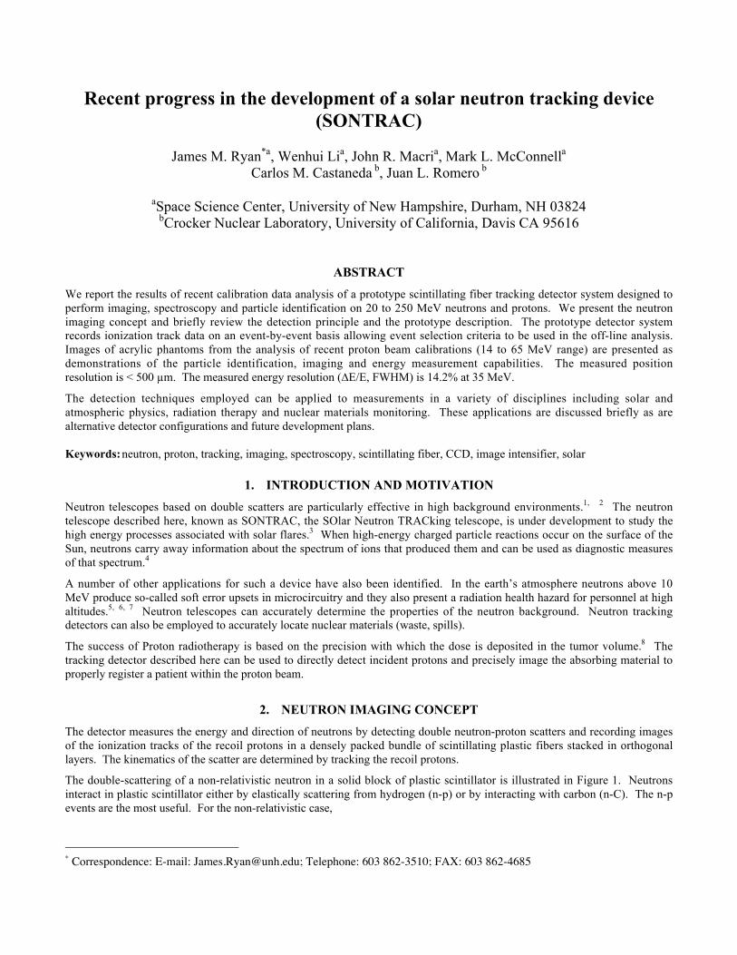
The double-scattering of a non-relativistic neutron in a solid block of plastic scintillator is illustrated in Figure 1. Neutronsinteract in plastic scintillator either by elastically scattering from hydrogen (n-p) or by interacting with carbon (n-C). The n-pevents are the most useful. For the non-relativistic case,
* Correspondence: E-mail: [email protected]; Telephone: 603 862-3510; FAX: 603 862-4685
sin2 f ¢ n = cos2 f ¢ p =E ¢ p
E ¢ n + E ¢ p =
E ¢ p
En(1)
where En is the incident neutron energy; En’ and Ep’ are the scattered neutron and photon energies, respectively; fn’ and fp’ arethe neutron and proton scatter angles, respectively. The kinematics of nonrelativistic scattering further dictate that thescattered neutron and proton momenta are perpendicular to one another.
If the incident direction of a neutron is known, then the measurement of the energy and direction of a recoil proton in a singlescatter is sufficient to determine the incident neutron energy. In particular, if the incident direction is known, then fn’ isdetermined and the neutron energy is
En =E ¢ p
cos2 f ¢ p (2)
A more general approach, however, is provided by double-scatter events (Figure 1). If both recoil protons in a double scatterevent are measured, then the energy and incident direction of the neutron are uniquely determined. The angular and energy
resolution depend upon the ability to precisely measure the energy anddirection of the recoil protons. Double scatter events can be used to measureneutron intensity from an extended source such as the secondary neutronsproduced in the atmosphere by the primary cosmic radiation. For solarneutrons, double scatter events are also preferred, because they allow for amore complete separation of the source signal from the ambient background.
3. DETECTOR CONCEPT
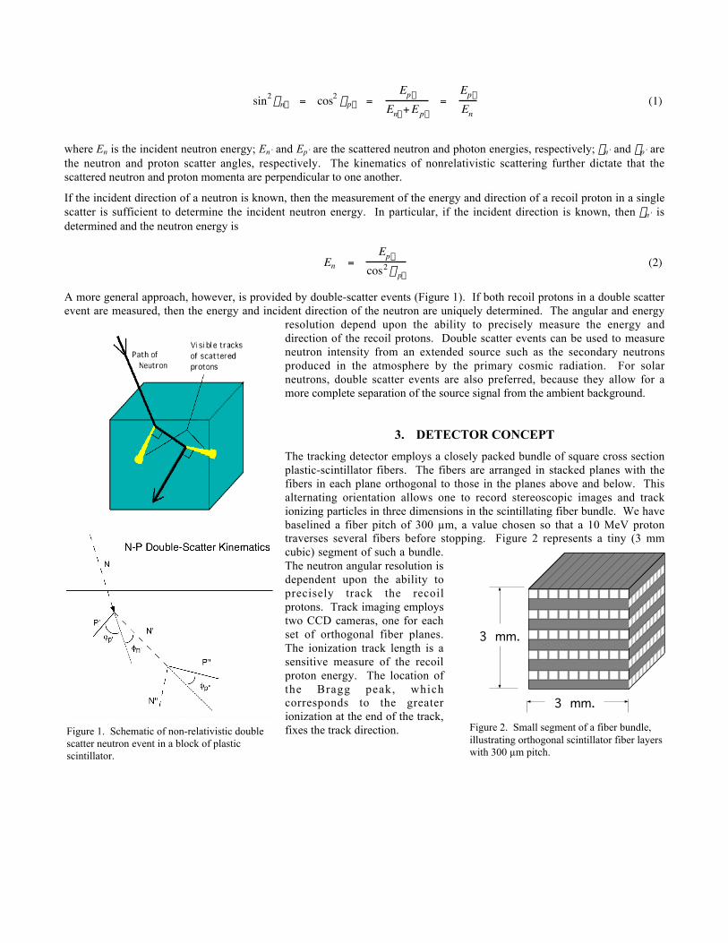
The tracking detector employs a closely packed bundle of square cross sectionplastic-scintillator fibers. The fibers are arranged in stacked planes with thefibers in each plane orthogonal to those in the planes above and below. Thisalternating orientation allows one to record stereoscopic images and trackionizing particles in three dimensions in the scintillating fiber bundle. We havebaselined a fiber pitch of 300 µm, a value chosen so that a 10 MeV protontraverses several fibers before stopping. Figure 2 represents a tiny (3 mmcubic) segment of such a bundle.The neutron angular resolution isdependent upon the ability toprecisely track the recoilprotons. Track imaging employstwo CCD cameras, one for eachset of orthogonal fiber planes.The ionization track length is asensitive measure of the recoilproton energy. The location ofthe Bragg peak, whichcorresponds to the greaterionization at the end of the track,fixes the track direction.
3 mm.
3 mm.
Figure 2. Small segment of a fiber bundle,illustrating orthogonal scintillator fiber layerswith 300 µm pitch.
Figure 1. Schematic of non-relativistic doublescatter neutron event in a block of plasticscintillator.
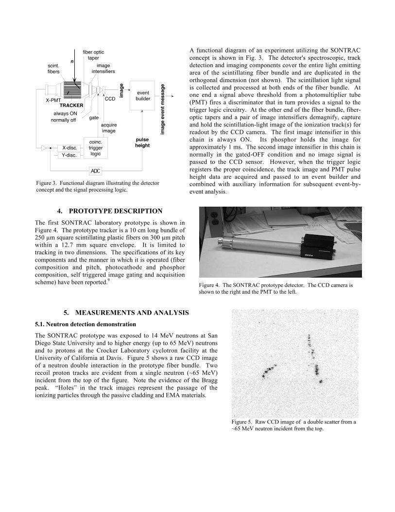
A functional diagram of an experiment utilizing the SONTRACconcept is shown in Fig. 3. The detector's spectroscopic, trackdetection and imaging components cover the entire light emittingarea of the scintillating fiber bundle and are duplicated in theorthogonal dimension (not shown). The scintillation light signalis collected and processed at both ends of the fiber bundle. Atone end a signal above threshold from a photomultiplier tube(PMT) fires a discriminator that in turn provides a signal to thetrigger logic circuitry. At the other end of the fiber bundle, fiber-optic tapers and a pair of image intensifiers demagnify, captureand hold the scintillation-light image of the ionization track(s) forreadout by the CCD camera. The first image intensifier in thischain is always ON. Its phosphor holds the image forapproximately 1 ms. The second image intensifier in this chain isnormally in the gated-OFF condition and no image signal ispassed to the CCD sensor. However, when the trigger logicregisters the proper coincidence, the track image and PMT pulseheight data are acquired and passed to an event builder andcombined with auxiliary information for subsequent event-by-event analysis.
4. PROTOTYPE DESCRIPTION
The first SONTRAC laboratory prototype is shown inFigure 4. The prototype tracker is a 10 cm long bundle of250 µm square scintillating plastic fibers on 300 µm pitchwithin a 12.7 mm square envelope. It is limited totracking in two dimensions. The specifications of its keycomponents and the manner in which it is operated (fibercomposition and pitch, photocathode and phosphorcomposition, self triggered image gating and acquisitionscheme) have been reported.9
5. MEASUREMENTS AND ANALYSIS
5.1. Neutron detection demonstration
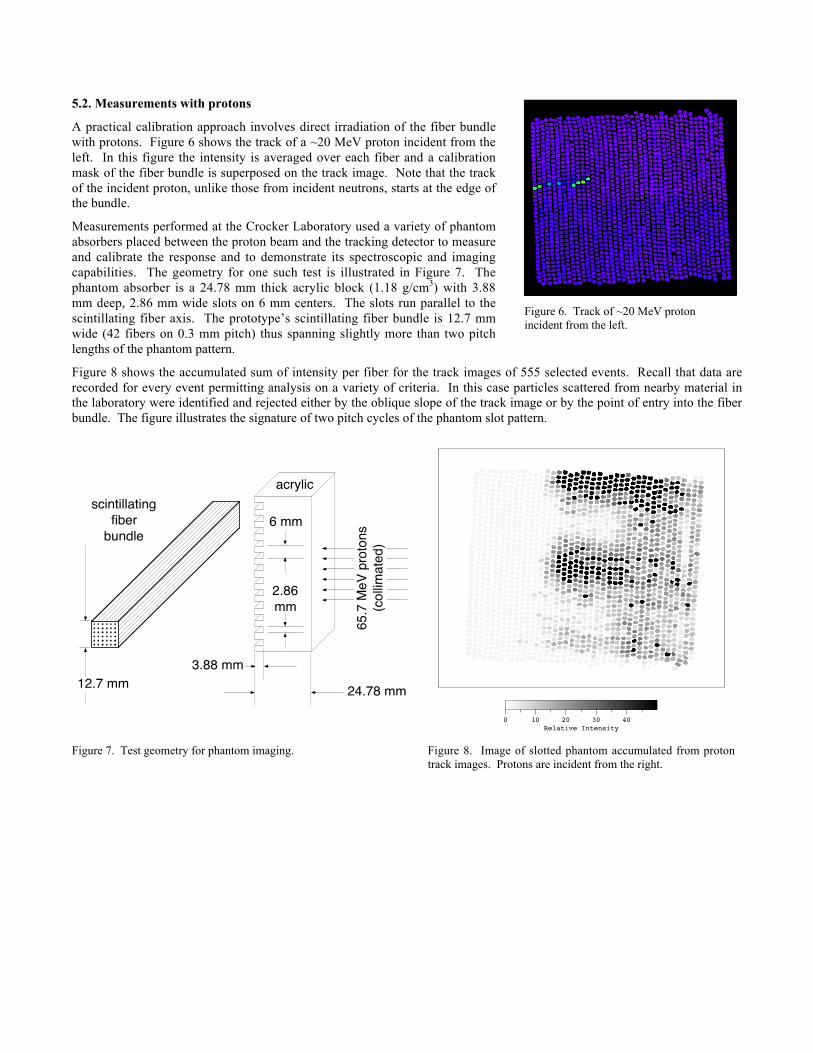
The SONTRAC prototype was exposed to 14 MeV neutrons at SanDiego State University and to higher energy (up to 65 MeV) neutronsand to protons at the Crocker Laboratory cyclotron facility at theUniversity of California at Davis. Figure 5 shows a raw CCD imageof a neutron double interaction in the prototype fiber bundle. Tworecoil proton tracks are evident from a single neutron (~65 MeV)incident from the top of the figure. Note the evidence of the Braggpeak. “Holes” in the track images represent the passage of theionizing particles through the passive cladding and EMA materials.
Figure 4. The SONTRAC prototype detector. The CCD camera isshown to the right and the PMT to the left.
Figure 5. Raw CCD image of a double scatter from a~65 MeV neutron incident from the top.
. scint.fibers
X-PMT
imageintensifiers
CCD
n
coinc.triggerlogic
X-disc.Y-disc.
eventbuilder
ADC
imag
e
pulseheight
gateacquireimage im
age
even
t mes
sage
TRACKERalways ON
fiber optictaper
normally off
Figure 3. Functional diagram illustrating the detectorconcept and the signal processing logic.
5.2. Measurements with protons
A practical calibration approach involves direct irradiation of the fiber bundlewith protons. Figure 6 shows the track of a ~20 MeV proton incident from theleft. In this figure the intensity is averaged over each fiber and a calibrationmask of the fiber bundle is superposed on the track image. Note that the trackof the incident proton, unlike those from incident neutrons, starts at the edge ofthe bundle.
Measurements performed at the Crocker Laboratory used a variety of phantomabsorbers placed between the proton beam and the tracking detector to measureand calibrate the response and to demonstrate its spectroscopic and imagingcapabilities. The geometry for one such test is illustrated in Figure 7. Thephantom absorber is a 24.78 mm thick acrylic block (1.18 g/cm3) with 3.88mm deep, 2.86 mm wide slots on 6 mm centers. The slots run parallel to thescintillating fiber axis. The prototype’s scintillating fiber bundle is 12.7 mmwide (42 fibers on 0.3 mm pitch) thus spanning slightly more than two pitchlengths of the phantom pattern.
Figure 8 shows the accumulated sum of intensity per fiber for the track images of 555 selected events. Recall that data arerecorded for every event permitting analysis on a variety of criteria. In this case particles scattered from nearby material inthe laboratory were identified and rejected either by the oblique slope of the track image or by the point of entry into the fiberbundle. The figure illustrates the signature of two pitch cycles of the phantom slot pattern.
.
12.7 mm 24.78 mm
acrylicscintillating
fiberbundle
6 mm
2.86mm
3.88 mm
65.7
MeV
pro
tons
(col
limat
ed)
0 10 20 30 40Relative Intensity
Figure 7. Test geometry for phantom imaging. Figure 8. Image of slotted phantom accumulated from protontrack images. Protons are incident from the right.
0 125 250 375
0
100
200
300
col
row
0 10 20 30 40UC_01_20_AVE_tiff
Figure 6. Track of ~20 MeV protonincident from the left.
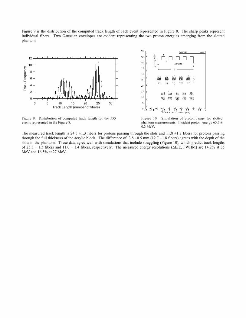
Figure 9 is the distribution of the computed track length of each event represented in Figure 8. The sharp peaks representindividual fibers. Two Gaussian envelopes are evident representing the two proton energies emerging from the slottedphantom.
12
10
8
6
4
2
0
302520151050Track Length (number of fibers)
Figure 9. Distribution of computed track length for the 555events represented in the Figure 8.
Figure 10. Simulation of proton range for slottedphantom measurements. Incident proton energy 65.7 ±0.3 MeV.
The measured track length is 24.5 ±1.3 fibers for protons passing through the slots and 11.8 ±1.3 fibers for protons passingthrough the full thickness of the acrylic block. The difference of 3.8 ±0.5 mm (12.7 ±1.8 fibers) agrees with the depth of theslots in the phantom. These data agree well with simulations that include straggling (Figure 10), which predict track lengthsof 25.3 ± 1.3 fibers and 11.0 ± 1.4 fibers, respectively. The measured energy resolutions (∆E/E, FWHM) are 14.2% at 35MeV and 16.5% at 27 MeV.
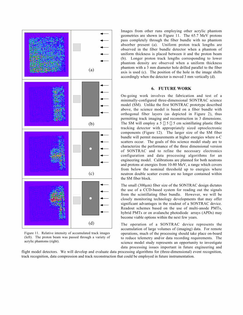
Images from other runs employing other acrylic phantomgeometries are shown in Figure 11. The 65.7 MeV protonspass completely through the fiber bundle with no phantomabsorber present (a). Uniform proton track lengths areobserved in the fiber bundle detector when a phantom ofuniform thickness is placed between it and the proton beam(b). Longer proton track lengths corresponding to lowerphantom density are observed when a uniform thicknessphantom with a 3 mm diameter hole drilled parallel to the fiberaxis is used (c). The position of the hole in the image shiftsaccordingly when the detector is moved 3 mm vertically (d).
6. FUTURE WORK
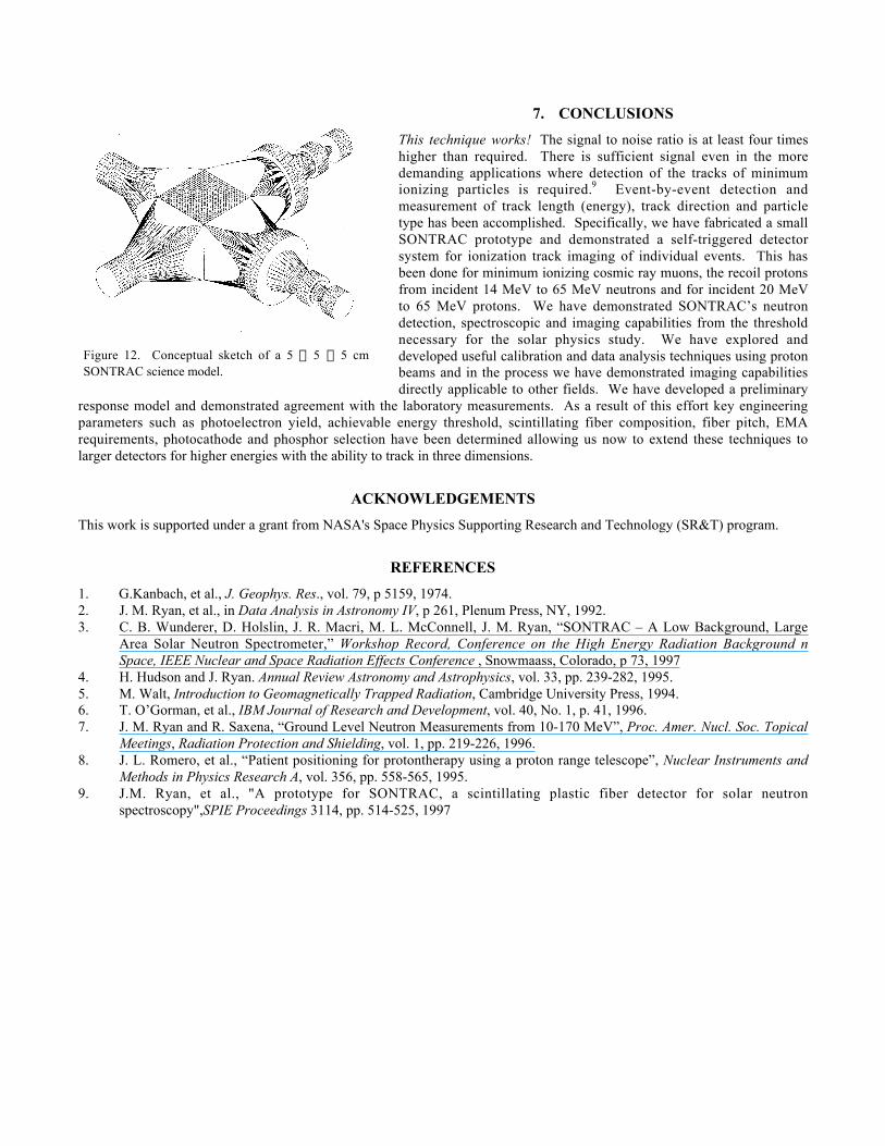
On-going work involves the fabrication and test of aminimally-configured three-dimensional SONTRAC sciencemodel (SM). Unlike the first SONTRAC prototype describedabove, the science model is based on a fiber bundle withorthogonal fiber layers (as depicted in Figure 2), thuspermitting track imaging and reconstruction in 3 dimensions.The SM will employ a 5 ¥ 5 ¥ 5 cm scintillating plastic fibertracking detector with appropriately sized optoelectroniccomponents (Figure 12). The larger size of the SM fiberbundle will permit measurements at higher energies where n-Cscatters occur. The goals of this science model study are tocharacterize the performance of the three dimensional versionof SONTRAC and to refine the necessary electronicsconfiguration and data processing algorithms for anengineering model. Calibrations are planned for both neutronsand protons at energies from 10-80 MeV, a range which coversfrom below the nominal threshold up to energies whereneutron double scatter events are no longer contained withinthe SM fiber block.
The small (300µm) fiber size of the SONTRAC design dictatesthe use of a CCD-based system for reading out the signalsfrom the scintillating fiber bundle. However, we will beclosely monitoring technology developments that may offersignificant advantages in the readout of a SONTRAC device.Readout schemes based on the use of multi-anode PMTs,hybrid PMTs or on avalanche photodiode arrays (APDs) maybecome viable options within the next few years.
The operation of a SONTRAC device represents theaccumulation of large volumes of (imaging) data. For remoteoperations, much of the processing should take place on-boardto reduce telemetry and/or data recording requirements. Thescience model study represents an opportunity to investigatedata processing issues important in future engineering and
flight model detectors. We will develop and evaluate data processing algorithms for (three-dimensional) event recognition,track recognition, data compression and track reconstruction that could be employed in future instrumentation.
(a)
(b)
(c)
(d)
Figure 11. Relative intensity of accumulated track images(left). The proton beam was passed through a variety ofacrylic phantoms (right).
7. CONCLUSIONS
This technique works! The signal to noise ratio is at least four timeshigher than required. There is sufficient signal even in the moredemanding applications where detection of the tracks of minimumionizing particles is required.9 Event-by-event detection andmeasurement of track length (energy), track direction and particletype has been accomplished. Specifically, we have fabricated a smallSONTRAC prototype and demonstrated a self-triggered detectorsystem for ionization track imaging of individual events. This hasbeen done for minimum ionizing cosmic ray muons, the recoil protonsfrom incident 14 MeV to 65 MeV neutrons and for incident 20 MeVto 65 MeV protons. We have demonstrated SONTRAC’s neutrondetection, spectroscopic and imaging capabilities from the thresholdnecessary for the solar physics study. We have explored anddeveloped useful calibration and data analysis techniques using protonbeams and in the process we have demonstrated imaging capabilitiesdirectly applicable to other fields. We have developed a preliminary
response model and demonstrated agreement with the laboratory measurements. As a result of this effort key engineeringparameters such as photoelectron yield, achievable energy threshold, scintillating fiber composition, fiber pitch, EMArequirements, photocathode and phosphor selection have been determined allowing us now to extend these techniques tolarger detectors for higher energies with the ability to track in three dimensions.
ACKNOWLEDGEMENTS
This work is supported under a grant from NASA's Space Physics Supporting Research and Technology (SR&T) program.
REFERENCES
1. G.Kanbach, et al., J. Geophys. Res., vol. 79, p 5159, 1974.2. J. M. Ryan, et al., in Data Analysis in Astronomy IV, p 261, Plenum Press, NY, 1992.3. C. B. Wunderer, D. Holslin, J. R. Macri, M. L. McConnell, J. M. Ryan, “SONTRAC – A Low Background, Large
Area Solar Neutron Spectrometer,” Workshop Record, Conference on the High Energy Radiation Background nSpace, IEEE Nuclear and Space Radiation Effects Conference , Snowmaass, Colorado, p 73, 1997
4. H. Hudson and J. Ryan. Annual Review Astronomy and Astrophysics, vol. 33, pp. 239-282, 1995.5. M. Walt, Introduction to Geomagnetically Trapped Radiation, Cambridge University Press, 1994.6. T. O’Gorman, et al., IBM Journal of Research and Development, vol. 40, No. 1, p. 41, 1996.7. J. M. Ryan and R. Saxena, “Ground Level Neutron Measurements from 10-170 MeV”, Proc. Amer. Nucl. Soc. Topical
Meetings, Radiation Protection and Shielding, vol. 1, pp. 219-226, 1996.8. J. L. Romero, et al., “Patient positioning for protontherapy using a proton range telescope”, Nuclear Instruments and
Methods in Physics Research A, vol. 356, pp. 558-565, 1995.9. J.M. Ryan, et al., "A prototype for SONTRAC, a scintillating plastic fiber detector for solar neutron
spectroscopy",SPIE Proceedings 3114, pp. 514-525, 1997
Figure 12. Conceptual sketch of a 5 ¥ 5 ¥ 5 cmSONTRAC science model.