New Approaches to Solar Tracking and Concentration through ...
144
Doctoral theses at NTNU, 2020:405 Håkon J. D. Johnsen New Approaches to Solar Tracking and Concentration through Numerical Optimization of Lens Arrays Doctoral thesis NTNU Norwegian University of Science and Technology Thesis for the Degree of Philosophiae Doctor Faculty of Engineering Department of Mechanical and Industrial Engineering
-
Upload
khangminh22 -
Category
Documents
-
view
0 -
download
0
Transcript of New Approaches to Solar Tracking and Concentration through ...

ISBN 978-82-471-9743-1 (printed ver.)ISBN 978-82-471-9791-2 (electronic ver.)
ISSN 1503-8181 (printed ver.)ISSN 2703-8084 (online ver.)
Doctoral theses at NTNU, 2020:405
Håkon J. D. Johnsen
New Approaches to SolarTracking and Concentrationthrough NumericalOptimization of Lens Arrays
Doc
tora
l the
sis
Doctoral theses at N
TNU
, 2020:405H
åkon J. D. Johnsen
NTN
UN
orw
egia
n U
nive
rsity
of S
cien
ce a
nd T
echn
olog
yTh
esis
for t
he D
egre
e of
Philo
soph
iae
Doc
tor
Facu
lty o
f Eng
inee
ring
Dep
artm
ent o
f Mec
hani
cal a
nd In
dust
rial
Engi
neer
ing

Thesis for the Degree of Philosophiae Doctor
Trondheim, December 2020
Norwegian University of Science and TechnologyFaculty of EngineeringDepartment of Mechanical and Industrial Engineering
Håkon J. D. Johnsen
New Approaches to SolarTracking and Concentrationthrough Numerical Optimizationof Lens Arrays

NTNUNorwegian University of Science and Technology
Thesis for the Degree of Philosophiae Doctor
Faculty of EngineeringDepartment of Mechanical and Industrial Engineering
© Håkon J. D. Johnsen
ISBN 978-82-471-9743-1 (printed ver.)ISBN 978-82-471-9791-2 (electronic ver.)ISSN 1503-8181 (printed ver.)ISSN 2703-8084 (online ver.)
Doctoral theses at NTNU, 2020:405
Printed by NTNU Grafisk senter

Abstract
Solar concentrators are essential for enabling several solar energy applica-tions, including high-efficiency photovoltaic conversion and high-temperaturesolar thermal energy. These concentrators require accurate solar tracking,commonly performed by rotating them towards the sun, which adds to thebulk and complexity of the system.
In this thesis, we investigate optically tracking the sun using millimeter-scaletranslation instead of rotating the complete concentrator — a concept knownas tracking integration. We show how the performance of these systems canbe pushed beyond the current state of the art through a broad explorationof the design space using a custom sequential ray-tracer in combination withmemetic multi-objective optimization algorithms.
We explore two classes of tracking integration: beam-steering lens arraysthat consist of an afocal stack of lens arrays, and microtracking concentratorsthat concentrate sunlight to an array of discrete focal spots where micro-PVcells can convert the solar energy to electricity. Further, we propose possibleétendue-squeezing solar concentrator designs that may benefit from trackingintegration.
First, we perform a broad exploration of beam-steering lens array configu-rations for full-day stationary solar tracking. We identify several promisingconfigurations, including one capable of redirecting sunlight into a < 2◦
divergence half-angle with a 73.4% average yearly efficiency. Second, weidentify two microtracking configurations that achieve > 2000x concentrationratio at a two-axis ±60◦tracking range. Finally, we demonstrate a line-focusconcentrator with a simulated effective concentration ratio of 218x at a ±1◦
acceptance angle that employs étendue squeezing to go beyond the conven-tional two-dimensional concentration limit. To the best of our knowledge,this is the first demonstration of how a line-focus concentrator can be directlydesigned as a three-dimensional concentrator to operate beyond the 2D limit(which is 57x at the ±1◦ acceptance angle). This concentrator, combined withbeam-steering lens arrays, may enable the development of a new class of high-concentration trough-like solar concentrators.
i

This thesis demonstrates how numerical optimization can be utilized to ex-plore a large design space, develop new concepts for solar tracking and con-centration, and contribute to the development of new applications for concen-trated sunlight. The method and the obtained results may contribute to thedevelopment of low-cost solar tracking and concentration. The optimizationproblem formulation and optimization algorithms, in general, may also unlocksolutions to other yet unexplored problems in nonimaging optics.
ii

Acknowledgements
It is the middle of May 2017. I am in the 4th year of my mechanical engi-neering studies and the semester is coming to an end. As I wrap up the workfor a course, I stumble across a paper — “Wide-angle planar microtrackingfor quasi-static microcell concentrating photovoltaics” by Jared S. Price andco-authors [5]. The field is unfamiliar, but the well-written paper completelycaptures my imagination, and I realize that THIS would be interesting to workon! Fast-forward half a year, and this field has become the topic of my Master’sthesis and eventually this PhD thesis. I am grateful to all the people whocontributed to making this exciting and unexpected journey a reality!
I especially want to thank my supervisor Jan Torgersen for believing in mywork and giving me the freedom to pursue this research direction based onmy interests and passion. Thank you for doing all the work behind the scenesto make this possible! I also want to thank my co-supervisor, Astrid Aksnes,for being exceptionally helpful and kind. Thank you for always finding timeto give feedback despite your busy schedule, and thank you for all your advice— both PhD related and about life in general. Additionally, I want to thankprofessor Ole Jørgen Nydal for co-supervising the Master’s thesis that sparkedthis research. Thank you for listening to all my wild plans and agreeing towork with me on it!
I appreciate my colleagues at the department for all the time we had togetherover these three years. With you, being at the office was always a goodexperience, no matter how deep we all were into our work. I am especiallythankful to Gaute Fotland for all the countless deep conversations over coffeeon dark winter mornings in our office. Thank you for sharing your wisdom,and for all your efforts to make office life more engaging for all of us!
I want to thank all my good friends in the city for making this such a nice placeto live all these years! I am especially thankful to Marie Stavdahl, ÅsmundStavdahl, Ingvild Furnes Lauvås, Nikolai Lauvås, and Oline Lauvås. Thankyou for always welcoming me and finding the right balance between giving
iii

me room to work and telling me that it’s about time I leave university and joinyou for dinner!
I am deeply thankful to my family for giving me a safe and nourishing child-hood, both in Voss and in Oslo. Hilde, thank you for always finding time forme when I visit. I admire your integrity and your values! Mum, thank you forall your support and encouragement, and for showing that my worth does notrest on any academic achievements. Dad, thank you for sparking my interestsin technology, engineering, and computer programming, and for all the deepand good conversations!
iv

Contributions
The work in this thesis was carried out at the Department of Mechanical andIndustrial Engineering at NTNU in Trondheim, Norway. The work was su-pervised by Associate Professor Jan Torgersen and co-supervised by ProfessorAstrid Aksnes.
The work was carried as part of the Micro and Nanoscale Design group, andwas internally financed by the university. Additionally, some work was done inthe NorFab cleanrooms. The Research Council of Norway is acknowledged forthe support to the Norwegian Micro- and Nano-Fabrication Facility, NorFab,project number 295864.
Publications
The following set of publications constitute this thesis:
Paper 1
H. J. D. Johnsen, J. Torgersen, and A. Aksnes, “Solar tracking using beam-steering lens arrays,” in Nonimaging Optics: Efficient Design for Illuminationand Solar Concentration XV, 2018.
H.J.D.J. initiated the research into beam-steering lens arrays, developed thesequential ray-tracer, created the phase-space visualizations and optimizationmethod, performed numerical simulations, analyzed the results, and preparedthe original draft. J.T. and A.A. supervised the work, reviewed manuscriptdrafts and contributed to the revision of the paper. The physical proof-of-conceptreported in Section 5 of the paper was developed as part of H.J.D.J.’s Master’sthesis.
v

Paper 2
H. J. D. Johnsen, J. Torgersen, and A. Aksnes, “High-concentration wide-angle tracking integration with stacked lens arrays,” in 15th InternationalConference on Concentrator Photovoltaic Systems (CPV-15), 2019.
H.J.D.J. proposed optimizing more advanced microtracking configurations, for-mulated the optimization problem, performed optimization and simulations, an-alyzed the results, and prepared the original draft. J.T. and A.A. supervised thework, reviewed manuscript drafts and contributed to the revision of the paper.
Paper 3
H. J. D. Johnsen, A. Aksnes, and J. Torgersen, “Pushing the limits of beam-steering lens arrays,” in Nonimaging Optics: Efficient Design for Illuminationand Solar Concentration XVI, 2019.
H.J.D.J. initiated the use of multi-objective optimization for beam-steering lensarrays, formulated the optimization problem, performed numerical simulations,analyzed the results, and prepared the original draft. J.T. and A.A. supervised thework, reviewed manuscript drafts and contributed to the revision of the paper.
Paper 4
H. J. D. Johnsen, A. Aksnes, and J. Torgersen, “High-performance stationarysolar tracking through multi-objective optimization of beam-steering lens ar-rays”, in Optics Express, 2020.
H.J.D.J. proposed the broad exploration of beam-steering lens array configura-tions, developed the approach for incorporating manufacturing tolerances in theoptimization, performed the large-scale numerical optimization, analyzed theresults, and prepared the original manuscript draft. J.T. and A.A. supervised thework, reviewed manuscript drafts and contributed to the revision of the paper.
vi

Paper 5
H. J. D. Johnsen, A. Aksnes, and J. Torgersen, “Beyond the 2D limit: Étendue-squeezing line-focus solar concentrators”, in Optics Letters, doc. ID 406280,posted 17 November 2020, in press.
H.J.D.J. proposed the use of étendue-squeezing for line-focus solar concentrators,conceptualized the two design examples, performed numerical optimization, an-alyzed the results, and prepared the original manuscript draft. J.T. and A.A.supervised the work, reviewed manuscript drafts and contributed to the revisionof the paper.
Other dissemination
In addition to the papers listed above, the work was disseminated in thefollowing ways:
• H. J. D. Johnsen, A. Aksnes, and J. Torgersen, “Beam-steering lens ar-rays and ètendue-squeezing: a pathway towards a new class of solarconcentrators?,” SPIE Optics + Photonics 2020, 2020. (Presentation.Recording, Slides)
• H. J. D. Johnsen, A. Aksnes, and J. Torgersen, “Pushing the limits ofbeam-steering lens arrays,” SPIE Optics + Photonics 2019, 2019. (Pre-sentation. Recording, Slides)
• H. J. D. Johnsen, J. Torgersen, and A. Aksnes, “Design and fabricationof beam steering lens arrays through raytracing and maskless grayscalelithography,” 10th Annual Workshop of the Norwegian PhD Network onNanotechnology for Microsystems, 2019. (Presentation)
• H. J. D. Johnsen, A. Aksnes, and J. Torgersen, “High-ConcentrationWide-Angle Tracking Integration with Stacked Lens Arrays,” The 15thInternational Conference on Concentrator Photovoltaics (CPV-15), 2019.(Presentation. Slides)
vii

• H. J. D. Johnsen, J. Torgersen, and A. Aksnes, “Tracking-Integrated SolarEnergy Using Stacked Lens Arrays,” Norwegian Solar Cell Conference(NSCC) 2019, 2019. (Poster)
• H. J. D. Johnsen, J. Torgersen, and A. Aksnes, “Beam-steering lens arraysfor solar tracking,” First NTNU Young Researcher Clean Energy Sympo-sium, 2019. (Presentation)
• H. J. D. Johnsen, J. Torgersen, and A. Aksnes, “Beam-steering lens arraysfor solar tracking,” NTNU Nano Symposium 2018, 2018. (Presenta-tion)
• H. J. D. Johnsen, J. Torgersen, and A. Aksnes, “Solar tracking usingbeam-steering lens arrays,” SPIE Optics + Photonics 2018, 2018. (Pre-sentation. Recording)
• H. J. D. Johnsen, “Interview: Håkon J. Dugstad Johnsen – Beam steeringlens array for solar cooking,” SunPod podcast, 2018. (Podcast Inter-view)
• H. J. D. Johnsen, J. Torgersen, and O. J. Nydal, “Beam Steering LensArray for Solar Cooking,” The 10th International SolarZentrum Confer-ence for food quality, solar cooking, drying, farming, and gardening,2018. (Invited Presentation)
• H. J. D. Johnsen, J. Torgersen, and O. J. Nydal, “Beam Steering Lens Ar-ray for Solar Cooking,” Consolfood 2018, 2018. (Presentation. Slides)
viii

Contents
Abstract i
Acknowledgements iii
Contributions v
Contents ix
Abbreviations xi
1 Introduction 11.1 Research objectives, methods and scope . . . . . . . . . . . . . 21.2 Thesis overview . . . . . . . . . . . . . . . . . . . . . . . . . . . 3
2 Background 52.1 Solar concentration . . . . . . . . . . . . . . . . . . . . . . . . . 52.2 Tracking integration . . . . . . . . . . . . . . . . . . . . . . . . 72.3 Microtracking for CPV applications . . . . . . . . . . . . . . . . 92.4 Beam-steering . . . . . . . . . . . . . . . . . . . . . . . . . . . . 102.5 Beam-steering lens arrays . . . . . . . . . . . . . . . . . . . . . 102.6 Projection effects . . . . . . . . . . . . . . . . . . . . . . . . . . 132.7 Designing tracking-integrated systems . . . . . . . . . . . . . . 142.8 Ray-tracing and ray-sampling . . . . . . . . . . . . . . . . . . . 152.9 Memetic optimization . . . . . . . . . . . . . . . . . . . . . . . 162.10 Objective function formulation . . . . . . . . . . . . . . . . . . 182.11 Multi-objective optimization . . . . . . . . . . . . . . . . . . . . 192.12 Étendue Squeezing . . . . . . . . . . . . . . . . . . . . . . . . . 20
3 Research methods 23
ix

3.1 Custom Python-based ray-tracer . . . . . . . . . . . . . . . . . . 233.2 Formulation of the optimization problem . . . . . . . . . . . . . 253.3 Generating beam-steering lens array configurations . . . . . . . 273.4 Optimization of microtracking concentrators . . . . . . . . . . . 293.5 Optimization of étendue-squeezing solar concentrators . . . . . 29
4 Main Results 314.1 Beam-steering lens arrays . . . . . . . . . . . . . . . . . . . . . 314.2 Microtracking solar concentrators . . . . . . . . . . . . . . . . . 354.3 Étendue-squeezing line-focus solar concentrators . . . . . . . . 37
5 List of papers 415.1 Paper 1 . . . . . . . . . . . . . . . . . . . . . . . . . . . . . . . 415.2 Paper 2 . . . . . . . . . . . . . . . . . . . . . . . . . . . . . . . 435.3 Paper 3 . . . . . . . . . . . . . . . . . . . . . . . . . . . . . . . 455.4 Paper 4 . . . . . . . . . . . . . . . . . . . . . . . . . . . . . . . 475.5 Paper 5 . . . . . . . . . . . . . . . . . . . . . . . . . . . . . . . 49
6 Conclusions and further work 51
Bibliography 55
A Full-text papers 63Paper 1: Solar tracking using beam-steering lens arrays . . . . . . . . 65Paper 2: High-concentration wide-angle tracking integration with
stacked lens arrays . . . . . . . . . . . . . . . . . . . . . . . . . 79Paper 3: Pushing the limits of beam-steering lens arrays . . . . . . . 87Paper 4: High-performance stationary solar tracking through multi-
objective optimization of beam-steering lens arrays . . . . . . . 97Paper 5: Beyond the 2D limit: Étendue-squeezing line-focus solar
concentrators . . . . . . . . . . . . . . . . . . . . . . . . . . . . 119
x Contents

List of Abbreviations
BSLA Beam-steering lens arrayBFGS Broyden–Fletcher–Goldfarb–Shanno algorithmCPV Concentrator photovoltaicsCSP Concentrated solar powerLED Light-emitting diodeMLA Micro-lens arrayMOEA/D Multi-objective evolutionary algorithm based on decompositionNA Numerical apertureNSGA Non-dominated sorting genetic algorithmPMMA Poly(methyl methacrylate)PV PhotovoltaicsRMS Root mean squareSLSQP Sequential least squares programming algorithmSMS Simultaneous multiple surface methodSMS3D Three-dimensional simultaneous multiple surface method
Contents xi


Introduction 1In recent years, solar energy deployment has grown rapidly with the advent oflow-cost photovoltaics (PV) technology. Conventional PV systems utilize sun-light without concentration, but several additional applications and benefitscan be enabled by introducing optical concentration to the sunlight. However,solar concentration introduces the additional complexity that concentratingoptics needs to track the sun’s movement across the sky. In traditional concen-trators, solar tracking is implemented by rotating the entire optical system toface the sun, with the mechanical bulk and complexity that this entails.
In recent years there has been increasing research into developing alternativeapproaches to solar tracking. One approach is using arrays of micro-opticalsystems for active integrated tracking. These micro-optical systems can be de-signed to track the sun’s movement across the sky using micro-movements ortunable optical properties, providing concentrated sunlight without extensiveexternal tracking systems as illustrated in Figure 1.1. This thesis investigatesthe development, achievable performance, and potential use cases of thesetracking-integrated systems, with a focus on a variant known as beam-steeringlens arrays.
1

External tracking Internal tracking
Optical system dynamicallycompensates for incidence angle
Fig. 1.1.: Tracking integration performs solar tracking as part of the optical design,reducing or eliminating the need for rotating the concentrator to face thesun.
1.1 Research objectives, methods and scope
The overall aim of this thesis was to investigate the potential of performing so-lar tracking using tracking-integrated designs, with a focus on beam-steeringlens arrays. This involved the following set of objectives:
1. Developing a design method capable of designing beam-steering lensarrays and related tracking-integrated optical systems.
2. Exploring the design space of tracking-integrated optics, and identifyingpotentially promising designs.
3. Investigating new approaches to solar concentration enabled by the ad-dition of tracking integration.
In addition to these objectives, some work was carried out towards proof-of-concept fabrication using grayscale lithography, to physically demonstrate thedevelopments from the thesis. This fabrication effort has not yet reached thelevel of journal publication, and is therefore not included in this thesis.
2 Chapter 1 Introduction

1.2 Thesis overview
This thesis is written as a collection of 5 research papers reporting on differentaspects of the work towards achieving the objectives listed in Section 1.1.These papers are listed in Section 5, and their full text is included in AppendixA. Objective 1 is covered by Papers 1, 2, and 4. Objective 2 is covered byPapers 3 and 4. Objective 3 is covered by Paper 5.
The following chapters cover the background for the work in this thesis, anoutline of the methods used, and a brief report and discussion of the mostimportant results. The full-text version of each paper then follows in theappendix of the thesis.
1.2 Thesis overview 3


Background 2This chapter briefly introduces the basics of solar concentration, tracking in-tegration, and numerical optimization, laying the groundwork for the workcarried out as part of this thesis.
2.1 Solar concentration
The power of concentrated sunlight has been known for millennia [6]. It wasnot until the 1960s and 1970s that a more rigorous research field was estab-lished, researching how the concentrating optics can be designed to achieveideal or close to ideal energy transfer — a field known as Nonimaging Optics[7, 8]. This field brought a deeper understanding of how the fundamentallimits of optical concentration could be achieved, and illuminated the deepconnections between geometrical optics and thermodynamics [9].
The use of concentrated sunlight enables multiple use cases that are notachievable with non-concentrated sunlight, including electricity conversionwith high-efficiency multi-junction solar cells [10], high-temperature thermalenergy [11], direct catalysis of chemical reactions [12], or solar lighting[13].
Mirrors or lenses are used to optically concentrate the sunlight for these ap-plications. These concentrators depend upon being accurately aimed towardsthe sun to enable high optical concentration. The amount of concentration inair is fundamentally limited by Equation 2.1, where θ represents acceptancehalf-angle of the concentrator [7].
Cmax =( 1
sin θ
)2(2.1)
5

The acceptance angle must at a minimum be wide enough for the divergencehalf-angle of sunlight, at θ ≈ 0.27◦[14, p. 49]. This gives a maximumconcentration ratio of Cmax ≈ 45 000. In most practical applications, theachievable concentration ratio is much lower, due to tolerances for trackingerrors and imperfect optics. The decline in concentration ratio with increasedacceptance angle means that accurate solar tracking is necessary for high-concentration applications.
For some applications, especially thermal applications, it can be beneficial toconcentrate sunlight to a line-focus. This enables heat extraction through aheat-transfer fluid circulated through a receiver tube as illustrated in Figure2.1, and allows the use of simplified one-axis solar tracking about the axis ofthis receiver tube.
y
z
x
Sunlight, redirected towards the receivertube
Fig. 2.1.: Example of a line-focus concentrator, in the form of a parabolic trough.The reflector concentrates sunlight towards the receiver tube, where a heat-transfer fluid is used to extract the heat.
6 Chapter 2 Background

Line-focus concentrators are commonly designed by extruding two-dimensionalconcentrator geometries, known as linear concentrators. The translationallysymmetric two-dimensional profile of these linear concentrators means thattheir solar concentration is limited by the 2D concentration limit [7]:
Cmax,2D = 1sin θmax
. (2.2)
For a solar divergence half-angle of θ = 0.27◦, the limit is approximately 212x,with commercial systems operating at a fraction of this limit [15].
It has been shown that the concentration ratio of linear primary concentra-tors can be boosted beyond the 2D concentration limit by introducing three-dimensional secondary concentrators close to the line-focus to break the trans-lational symmetry, reaching concentration ratios of 300x with one-axis po-lar tracking [16], or >1000x with two-axis tracking [17, 18]. These sec-ondary concentrators achieve their increased concentration ratio by usingthree-dimensional concentrators to break the line-focus into a set of smallpoint- or line-foci. Therefore, they are primarily useful for discrete receiverssuch as PV cells, not tubular receivers commonly used for concentrated solarpower (CSP) applications. It has also been shown that the 2D limit can be sur-passed using nominally linear concentrators where the translational symmetryis broken by ridges in the concentrator, but these have focused on relativelylarge acceptance angles suitable for stationary solar concentration[19, 20,21].
2.2 Tracking integration
Conventional solar concentrators are rotated to follow the sun’s apparentmovement across the sky — either to point directly towards the sun usinga dual-axis solar tracker, or to align its normal vector in the same plane asthe sun and the axis of rotation using a single-axis solar tracker. Rotating thesystem to face the sun enables the possibility of high optical concentration.
2.2 Tracking integration 7

At the same time, it also ensures that the projected area of the concentrator,as seen from the sun, is as large as possible — maximizing the conversionper concentrator area as further discussed in Chapter 2.6. Still, the rotationmotion also has drawbacks, including mechanical bulk and complexity, sen-sitivity to wind loads, and difficulties being mounted on locations such asrooftops [22].
Recent developments in solar tracking and concentration have demonstratedhow solar tracking can be performed optically instead of rotating the con-centrator to follow the sun. In this manner, large mechanical structures forsolar tracking and concentration can be replaced by small trackers integratedinto a planar form factor. This development has mainly been carried outwithin the field of concentrator photovoltaics (CPV) [23]. Less work hasbeen carried out to implement similar techniques for other solar energy fieldssuch as concentrated solar power (CSP). This tracking integration enablesthe implementation of solar concentration in form factors not traditionallysuitable for such concentration.
Redirected collimated sunlightTo be concentrated by solar concentrator.
Array of PV cellsTracking motion
a b
Fig. 2.2.: Lens-arrays can be used to achieve tracking integration, both in the form of(a) microtracking solar concentrators, useful for CPV applications, as wellas (b) beam-steering lens arrays useful for CSP applications.
Tracking-integration for CPV applications commonly takes the form of what isknown as microtracking concentrators. These concentrators split the light intomany parallel paths, and each path performs tracking using micro-movementswhile also concentrating the sunlight to many discrete focal spots, as illus-trated in Figure 2.2a. For other applications such as CSP applications, the
8 Chapter 2 Background

receiver cannot be made small to correspond to each of the individual lenslets.The tracking system can then instead be designed to emit collimated lightfor concentration by a larger concentrator, as illustrated in Figure 2.2b. Thegeneral concept is known as beam-steering, and the specific approach usingmovable lens arrays shown in Figure 2.2b, is known as beam-steering lensarrays1.
2.3 Microtracking for CPV applications
When designing tracking-integrated concentrators for CPV applications, theindividual PV cells can be made small enough to directly use the individualfocal points from the lenslets in a lens array, as illustrated in Figure 2.2a.These designs are known as microtracking concentrators. Early implementa-tions of this technique were developed by Kotsidas et al. in 2010 [22], firstusing lenses designed with the simultaneous multiple surface (SMS) method,and later using gradient index lenses [28]. At around the same time, Sweattet al. demonstrated a microtracking system designed for correcting coarseexternal tracking [29]. Hallas et al. demonstrated a microtracking conceptwhere instead of using PV cells at each focal point, the light was coupled intoa planar light guide [30].
Duerr et al. showed how the performance of microtracking concentratorscould be improved by using two lens arrays that could move relative to eachother [31, 32], and Price et al. showed how a catadioptric pair of lens arrayscould be used to achieve higher tracking range [5].
In 2018, Ito et al. demonstrated how an objective function could be for-mulated to design microtracking CPV systems optimized for average yearlyefficiency [33], allowing the system to be designed without explicitly choosinga specific tracking range.
1The same idea has previously been described using several different terms, including“beam steering with decentered microlens arrays”[24], “beam-deflecting microlens arraytelescopes” [25], “beam-scanning MLA system”[26], and “beam-steering array optics”[27].In this thesis, we consistently use the term “beam-steering lens arrays” (BSLA) as a generaldescriptive term for the concept.
2.3 Microtracking for CPV applications 9

Microtracking concentrators are currently being commercialized by the com-pany Insolight [34].
Some work has also been carried out to implement passive solar tracking usingrelated techniques, for instance, using phase-changing materials that locallyreact to the concentrated sunlight to actuate a coupling feature [35] or tomodulate the transparency of the material [36].
2.4 Beam-steering
Instead of concentrating the sunlight to many small discrete focal spots, an-other way to implement tracking integration is the concept of beam-steering,where collimated sunlight is emitted and can be concentrated by a separateconcentrator.
Several possible approaches to beam-steering of sunlight have been reportedin the literature in recent years. Some of the proposed concepts include mi-crofluidic prism arrays actuated using electrowetting [37], microfluidic beam-steering arrays [38], rotating prism arrays [39], rotating Fresnel-like lenses[40], and beam-steering lens arrays [27].
In this thesis, we have focused on beam-steering lens arrays. These systemsbenefit from relying on well-known geometrical optics and can likely be madecompatible with high-volume manufacturing processes such as injection mold-ing or roll-to-roll processes.
2.5 Beam-steering lens arrays
A beam-steering lens array consists of a set of lens arrays arranged in an afocalconfiguration, enabling beam-steering by relative lateral translation betweenthe lens arrays, as illustrated in Figure 2.2b [1]2. The concept was originally
2Portions of the description of beam-steering lens arrays in this section have been publishedin Paper 4 of this thesis [4]
10 Chapter 2 Background

proposed for steering of laser beams [41, 24, 26]. In 2012, Lin et al. proposedutilizing the same concept for single-axis solar tracking, while also proposinga design method based on the Simultaneous Multiple Surface (SMS) method[27]. In the Masters thesis leading up to this work, we extended the conceptto two-axis solar tracking for solar cooking applications [42].
f1 f2
Δxd ϕ
L1
L2
Fig. 2.3.: Paraxial working principle of a simple beam-steering lens array, showingone of the lens pairs. These lens pairs are then laid out next to each otherin a complete lens array.
Figure 2.3 shows the paraxial working principle of a basic beam-steering lensarray with a pair of lens arrays stacked in an afocal configuration. The lensarrays are separated by their combined focal lengths f1 + f2. The systemcan track incoming sunlight at an angle ϕ by translating the last lens array adistance ∆x such that it is always aligned with the image of the sun from thefirst lens array:
∆x = f1 tan ϕ. (2.3)
In order for all rays to reach the correct lenslet in the array L2, the second focallength must be smaller than the first. This leads to an angular magnificationfactor M :
M = f1f2
= 1 + 2f1d
tan ϕmax, (2.4)
where ϕmax is the highest supported angle of incidence for the beam-steeringlens array.
2.5 Beam-steering lens arrays 11

As discussed in Section 2.1, sunlight has an inherent divergence half-angleof approximately θ ≈ 0.27◦. The divergence is magnified by this angularmagnification factor M after passing through a beam-steering lens array. Theresulting magnified divergence half-angle limits the maximum achievable con-centration of a concentrator placed behind the beam-steering lens array, infollowing the concentration limit of Equation 2.1. To allow high concentrationratios, it is therefore desirable that the angular magnification of the system islow. This leads to a trade-off between the tracking range ϕmax, and divergenceangle θ for this simple paraxial model of a beam-steering lens array.
It has been shown that this magnification factor can be eliminated in laserbeam-steering systems by introducing an additional paraxial field lens to thesystem, where all three lens arrays have the same focal length f[24]. Thisshows the importance of design choices such as the number and order ofsurfaces when designing a beam-steering lens array.
While utilizing the same underlying principle, there are significant differencesbetween earlier systems for steering of laser beams [41, 24, 26] and a systemdesigned for solar tracking:
• In solar tracking, the beam-steering system receives sunlight from vary-ing directions and emits it in a fixed direction. The earlier proposedlaser systems [41, 24, 26] work in reverse, receiving the beam from afixed direction and emitting in a variable direction.
• In laser systems, the lens arrays usually work in the diffractive regime,and additional phase-shifting optics are required to enable continuousbeam-steering [24]. For solar tracking covering larger areas, the in-dividual lenslets can be made large enough so that the geometricaloptical approximation is appropriate, and the separate lenslets can beconsidered individually.
• The steering range used in previously proposed laser systems is 5◦ to15◦[43, 26, 44], allowing design considerations based mainly on theparaxial approximation. For stationary solar tracking, much larger steer-ing angles are required, and the paraxial approximation presented inthis section is no longer sufficient
12 Chapter 2 Background
• In solar tracking, the system must be able to handle broadband sunlight,requiring chromatic aberration to be taken into account.
This thesis therefore covers a further investigation into the achievable perfor-mance of beam-steering lens arrays designed for solar tracking applications.
2.6 Projection effects
Stationary receiver Receiv
er fac
ing th
e sun
A cos θ
A
Projected area of receiver
θ
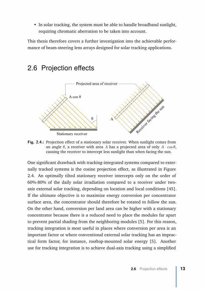
Fig. 2.4.: Projection effect of a stationary solar receiver. When sunlight comes froman angle θ, a receiver with area A has a projected area of only A · cos θ,causing the receiver to intercept less sunlight than when facing the sun.
One significant drawback with tracking-integrated systems compared to exter-nally tracked systems is the cosine projection effect, as illustrated in Figure2.4. An optimally tilted stationary receiver intercepts only on the order of60%-80% of the daily solar irradiation compared to a receiver under two-axis external solar tracking, depending on location and local conditions [45].If the ultimate objective is to maximize energy conversion per concentratorsurface area, the concentrator should therefore be rotated to follow the sun.On the other hand, conversion per land area can be higher with a stationaryconcentrator because there is a reduced need to place the modules far apartto prevent partial shading from the neighboring modules [5]. For this reason,tracking integration is most useful in places where conversion per area is animportant factor or where conventional external solar tracking has an imprac-tical form factor, for instance, rooftop-mounted solar energy [5]. Anotheruse for tracking integration is to achieve dual-axis tracking using a simplified
2.6 Projection effects 13

single-axis external tracker [32]. If a receiver is placed on a single-axis polar-aligned external tracker, it intercepts 96%-99% of the sunlight compared to areceiver under two-axis external tracking [45].
2.7 Designing tracking-integrated systems
Several powerful design methods have been developed in the field of Non-imaging Optics, including the edge ray principle, the SMS and SMS3D method,and the flow-line method [7]. These methods have primarily focused on thedesign of static optical systems, and are based on finding static optics thatcouple a predetermined set of incoming and outgoing ray-bundles.
A tracking-integrated system, on the other hand, is dynamic. It is designedto change its behavior depending on its orientation relative to the sun. Somework has focused on extending existing nonimaging methods for this newapplication. For instance, Lin et al. used a method based on the SMS methodfor designing their beam-steering lens arrays [27]. Duerr et al. developed atailored design method using Fermat’s principle to derive a set of differentialequations for a wide-angle lens used as a microtracking concentrator [32].
Alternatively, the tracking-integrated systems can be designed using numericaloptimization, as demonstrated by a number of micro-tracing designs [5, 33,34, 30]. Numerical optimization has higher computational demand thananalytic methods, but it enables the design of more complex systems withoutfirst needing to derive an analytic design method for the specific problem. It isalso straightforward to integrate additional effects into the design process, in-cluding chromatic aberration, behavior under expected manufacturing errors,and appropriate weighting of performance across a large field of view.
Numerical optimization involves parameterizing the optical system’s designby a set of parameters x, and defining an objective function f (x) that eval-uates the optical system and gives it a score based on a predefined set ofrequirements and goals. Often this score is formulated so that a lower numberrepresents a better system. In other words, it is a minimization problem. Anadditional set of constraints often needs to be fulfilled: ci (x) ≥ 0. In an
14 Chapter 2 Background

optical system, this can for instance be the requirement that all lenses have apositive thickness. Formally, this optimization problem can then be written as[46]3:
min f (x) (2.5)
such that ci (x) ≥0 (2.6)
This optimization problem is then passed to an optimization algorithm thatsystematically tries different values for the parameters x, searching for theparameters that give the best objective function value. Since f (x) can beevaluated for millions of different values of x during this search, numericaloptimization is a computationally expensive design method, and it is essentialthat the evaluation is as efficient as possible.
2.8 Ray-tracing and ray-sampling
In order to implement an objective function that gives a score to a specificdesign, it is necessary to simulate this optical system’s performance. In geo-metrical optical design-problems, like the ones described in this thesis, thisis commonly done using ray-tracing: Tracing many discrete rays through thesystem and inferring the whole system’s performance based on the behaviorof these rays. There is then a trade-off between the accuracy of the simulationand the computational requirements: Tracing a larger number of rays givesa more accurate estimate of the performance but also increases the computa-tional load.
Objective functions in nonimaging optics, including those used in this thesis,can often be considered a form of numerical integration. The objective func-tion integrates some figure of merit across the parameters of the irradiation.
3In the classical formulation of nonlinear optimization problems, they may include a set ofequality constraints cj (x) = 0 in addition to the inequality constraints presented here.Such equality constraints were not used in the optimization problems in this thesis.
2.8 Ray-tracing and ray-sampling 15

An objective function based on a random sampling of rays through the systemcan therefore be considered as a form of Monte-Carlo integration. For well-behaved numerical integration problems, it has been shown that the error ofMonte-Carlo integration can be reduced if the integration points are sampledfrom a low-discrepancy sequence instead of being truly random. This processis known as Quasi-Monte Carlo integration [47].
Quasi-Monte Carlo methods have been shown to have significantly improvedperformance compared to conventional Monte-Carlo methods for many differ-ent integration problems [47]. They have also been shown to give significantlyreduced errors when simulating optical devices [48].
2.9 Memetic optimization
The numerical optimization of nonimaging systems is challenged by the factthat most nonimaging optical problems are multimodal [7] — they containseveral local optima in addition to the global optimum.
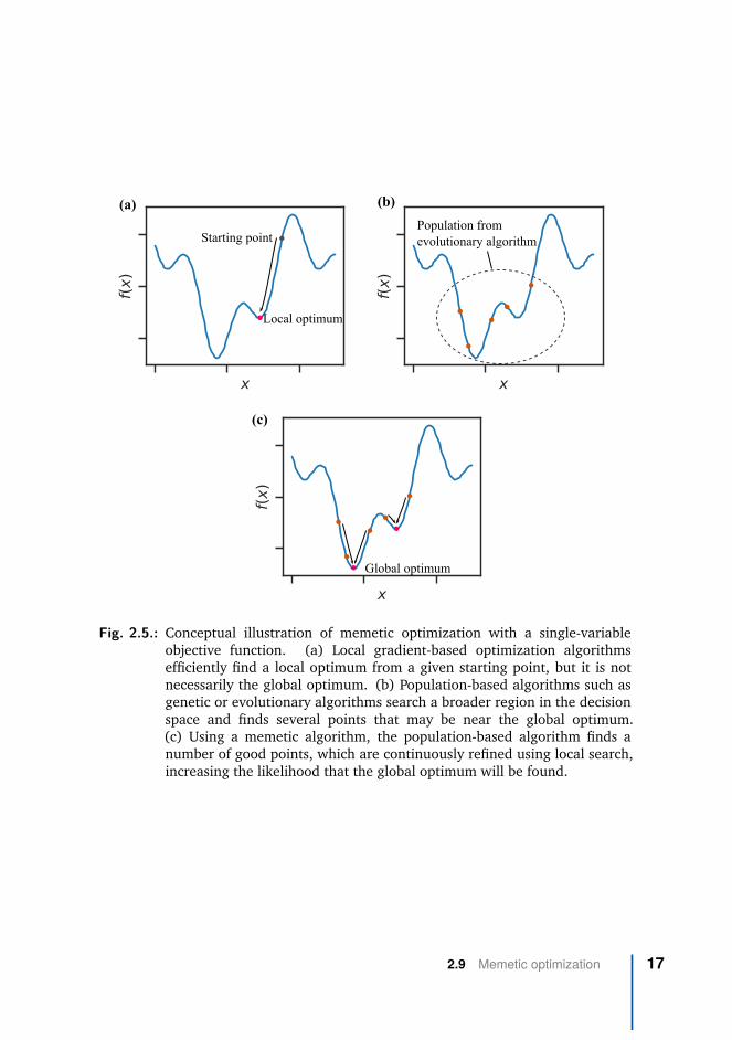
Classical gradient-based local optimization algorithms are highly efficient atfinding a local optimum, but this local optimum is not necessarily the globaloptimum for the optimization problem as illustrated in Figure 2.5. Conversely,population-based heuristic optimization algorithms such as evolutionary orgenetic algorithms have been shown to be less sensitive to local optima andsearch a wider region in the design landscape, but they are usually not verygood at finding the exact location of an optimum as illustrated in Figure2.5b.
A class of heuristic optimization algorithm known as memetic algorithms canbe used to create a hybrid of these two classes of optimization algorithms: Ituses local gradient-based algorithms for refining the individuals in the popula-tion used by the population-based algorithm [49], as illustrated in Figure 2.5c.Different memetic optimization algorithms have successfully been broadlyapplied to many different engineering problems [50].
16 Chapter 2 Background
Local optimum
Starting pointPopulation fromevolutionary algorithm
Global optimum
(a) (b)
(c)
Fig. 2.5.: Conceptual illustration of memetic optimization with a single-variableobjective function. (a) Local gradient-based optimization algorithmsefficiently find a local optimum from a given starting point, but it is notnecessarily the global optimum. (b) Population-based algorithms such asgenetic or evolutionary algorithms search a broader region in the decisionspace and finds several points that may be near the global optimum.(c) Using a memetic algorithm, the population-based algorithm finds anumber of good points, which are continuously refined using local search,increasing the likelihood that the global optimum will be found.
2.9 Memetic optimization 17

2.10 Objective function formulation
The optimization problem shown in Equation 2.5 is based on a single-valuedobjective function f (x), which evaluates the behavior of the optical systemx, and gives it a single numerical score to represent how well it achieves thedesign objective. However, the design of an optical system often involvesthe simultaneous optimization of several different objectives. In the case oftracking integration, these objectives may include:
• Maximizing the optical efficiency
• Maximizing the concentration ratio (or minimizing the divergence of theoutgoing light in the case of beam-steering systems)
• Maximizing the tracking range
• Minimizing the mechanical complexity of the design
Therefore, the formulation of an optimization problem involves finding a wayto combine these objectives into the single-valued objective function f (x) — aprocess known as scalarizing the problem. Several approaches have been usedto achieve this. A common choice is to use a predetermined tracking rangeand concentration ratio, and optimizing the system for maximum efficiencyunder these conditions. This approach was used, for instance, by Price et al.[5]. Another popular way to scalarize an optimization problem with multipleobjectives is to use a sum scalarization [51]:
f (x) =m∑
i=1wifi (x) (2.7)
where fi (x) is the individual objectives and wi is a set of weights determininghow they should be weighted in the scalarized objective function.
While maximizing the tracking range and maximizing the optical efficiencyare two distinct objectives, they both affect the yearly cumulative solar energycollected by the system. Ito et al. therefore elegantly showed how these
18 Chapter 2 Background

two objectives can be combined into the single objective of maximizing thiscollected cumulative solar energy [33], which they defined as:
Eannual =90◦∑
θi=0◦E (θi) · ηopt (θi) (2.8)
where θi is incidence angle, E (θi) is yearly cumulative solar radiation incidentat the incidence angle θi, and ηopt (θi) is the optical efficiency at incidenceangle θi.
With this objective formulation, it is no longer necessary to choose a prede-termined tracking range. Instead, the optimization algorithm can select theoptimum trade-off between tracking range and optical efficiency with the ulti-mate objective of maximizing the yearly cumulative solar energy collected.
2.11 Multi-objective optimization
As an alternative to scalarizing the optimization problem, it is possible to usealgorithms that directly work on multiple objectives, known as multi-objectiveoptimization algorithms. These algorithms do not look for a single optimalsolution, but instead look for a set of solutions that represent different levelsof trade-off between the multiple objectives in the optimization problem. Thisset of solutions is known as the Pareto front of the problem, as illustrated inFigure 2.6. In this case, the objective function becomes vector-valued:
min f (x) = (f1 (x) , f2 (x) , · · · ) (2.9)
such that ci (x) ≥0 (2.10)
Multi-objective optimization problems are often solved using evolutionaryor genetic algorithms, such as the NSGA II algorithm [52] or the MOEA/D
2.11 Multi-objective optimization 19

P1
P2
Fig. 2.6.: In multi-objective optimization, the algorithm tries to identify the set ofPareto-optimal solutions — solutions where no other solution exists thatimproves on all the objectives simultaneously. As an example, P2 is not aPareto optimal solution, because P1 has a better value for both objectives.Conversely, P1 is Pareto optimal — none of the other solutions are superiorin both objectives. The set of Pareto optimal solutions map out the trade-off between the objectives of the optimization problem.
algorithm [53]. In the same way as with single-objective optimization, it ispossible to combine these algorithms with local search algorithms to createhybrid memetic algorithms [54].
2.12 Étendue Squeezing
Many well-known designs in non-imaging optics are either translationallyor rotationally symmetric. This simplifies the design of the systems, but itcan also introduce additional limitations that are a consequence of thesesymmetries and not of the design problem itself. One way to utilize freeformsurfaces to go beyond these limitations is the concept of étendue squeezing[55], as introduced by Miñano and Benitez in 2005 [56].
20 Chapter 2 Background

Étendue squeezing is a way to achieve a lens with a different field of viewalong the x-axis and y-axis, achieved by squeezing the angular extent alongone axis while expanding it along the other axis so that the total étendueis conserved [55]. This type of lens solves the same nominal problem asan anamorphic lens in conventional imaging optics [57]. However, while ananamorphic lens achieves this squeezing of the field of view by changing theentrance pupil’s shape, an étendue-squeezing lens uses a set of parallel opticalpaths to obtain an entrance pupil as large as the lens itself, to facilitate theefficient transfer of energy.
A simple form of étendue squeezing lens is created when both object andimage is at infinity, and is illustrated in Figure 2.7. This lens uses many afocalpairs of lens surfaces to compress an optical beam in one axis while expandingit in the other axis, as illustrated in Figure 2.7a. If the ratio of compressionand expansion is 1:N where N is an integer, the lens pairs can be tessellatedso that they fill the complete front and back surface of a lens array, as shownin Figure 2.7b [58]. This specific type of étendue squeezing is known as anétendue-squeezing lens array, and was described by José Blen in his 2007 PhDdissertation [59]. The étendue-squeezing lens array trades angular extentalong one axis against angular extent along the other axis by a factor N, knownas the squeeze factor of the optics [58]. The idea has been demonstrated forapplications such as changing the aspect ratio of a collimated beam from anLED source [58].
As part of this thesis, we investigate whether this étendue squeezing principlealso may be used for solar concentration, specifically in combination withtracking integration.
2.12 Étendue Squeezing 21

Tesselated array ofétendue-squeezing elements
Incoming light
Outgoing light,compressed in x-directionand expanded in y-direction
xy
z
(a)
(b)
Fig. 2.7.: (a) Principle of étendue-squeezing using an afocal lens pair. (b) The lens-pairs can be tessellated into a complete étendue-squeezing lens array.
22 Chapter 2 Background

Research methods 3The primary research method in this thesis has been the numerical simulationand optimization of optical systems to fulfill the goals outlined in Section 1.1.This involved the development of a sequential ray-tracer explicitly designedfor simulating tracking-integrated systems, which was used to optimize beam-steering lens arrays, microtracking concentrators, and a new type of solarconcentrator based on étendue squeezing.
3.1 Custom Python-based ray-tracer
Several commercial software packages exist for the simulation and designof optical systems, and these have previously been used to design tracking-integrated and microtracking systems. For instance, LightTools was usedto design the microtracking concentrators by Ito et al. [33], while ZemaxOpticStudio was used to the design microtracking concentrators by Price etal. [5] and Hallas et al. [60]. We acquired Zemax OpticStudio for thework performed in this thesis, but we found that it did not fulfill all ourrequirements for performing a broad exploration of the design landscape fortracking-integration, mainly due to limitations in the formulation of objectivefunctions and optimization algorithms. We therefore developed a customPython-based ray-tracer to allow for greater flexibility.
The ray-tracer is a sequential ray-tracer designed specifically for optimizingtracking-integrated optical designs. It is written as a Python library, and com-piled using the LLVM-based Numba just-in-time compiler [61], enabling high-performance ray-tracing despite being written in an interpreted programminglanguage.
23
By having the architecture of a Python library, this ray-tracer opens up newpossibilities compared to the use of commercial optical design software, in-cluding:
• The use of a prototyping-friendly high-level language makes it possibleto experiment with various objective functions defined using the fullexpressiveness of this language, without the overhead of interprocesscommunication between the language and another commercial softwarepackage.
• By not relying on limited software licenses, it became possible to beflexible regarding the computational environment, and to perform large-scale optimization using computational resources from Google ComputeEngine.
• It became possible to take advantage of the existing scientific comput-ing ecosystem available from the Python programming language, in-cluding several optimization libraries with different optimization algo-rithms that have previously been shown to work well for optical designproblems[62].
• The flexibility of the implementation made it possible to implementefficient objective functions based on quasi-Monte Carlo methods asdescribed in Chapter 2.8, where the extra integration dimensions fromthe movable optical surfaces are included in the Quasi-Monte Carlointegration.
We emphasized ensuring numerical stability in the ray-tracer and making theobjective functions smooth and differentiable to enable the use of gradient-based optimization algorithms. The gradients were estimated using finite dif-ferences, as is also commonly done in commercial optical design software.
In numerous other scientific domains, it has been shown that superior ac-curacy and performance can be achieved if gradients are estimated explic-itly as part of the simulation, instead of using numerical finite differences.This is known as differentiable programming, and is usually implementedusing automatic differentiation[63]. Due to limitations in the combination
24 Chapter 3 Research methods

of Python and Numba, it was not straightforward to use automatic differ-entiation with the ray-tracer implemented as part of this thesis. Therefore,significant further performance improvements may be expected if this ray-tracer is re-implemented using an architecture that enables automatic differ-entiation.
3.2 Formulation of the optimization problem
In the initial optimization of beam-steering lens arrays for this thesis, wedefined our objective function as a sum scalarization between efficiency anddivergence of the outgoing light, and optimized the systems for a fixed track-ing range. Formally, this objective function could be written as:
min f (x) =m∑
i=1
(w1
1ηi (x)
+ w2 (δθi (x))2)
(3.1)
such that gj (x) ≤ 0 (3.2)
where w1 and w2 are relative weights applied to the efficiency and divergence.ηi(x) is the simulated efficiency for a ray-traced grid of rays with incidenceangle number i and optical system described by x. δθi (x) is the correspondingRMS divergence half-angle for field number i. m separate incidence anglesare evaluated across the tracking range of the BSLA. gj (x) is a set of inequal-ity constraints ensuring manufacturability, such as minimum and maximumthickness, and maximum lens curvature. When optimizing microtracking con-centrators, we used the same objective function but replaced RMS divergencehalf-angle with RMS spot size.
A drawback of this optimization problem was that the tracking range hadto be specified, and an explicit weighting between efficiency and divergencehad to be selected. In order to improve the optimization and enable a broadexploration of beam-steering lens array configurations, we reformulated theoptimization problem using an approach inspired by Ito et al.’s formulation
3.2 Formulation of the optimization problem 25

as described in Chapter 2.10. We defined an average yearly efficiency of thebeam-steering lens array:
η (x, θmax) = Eout (x, θmax)Ein
, (3.3)
where Ein is the yearly direct irradiation received by the beam-steering lens ar-ray surface, and Eout (x, θmax) is the yearly irradiation successfully redirectedby the beam-steering lens array within the permitted exit cone ±θmax.
Using this average yearly efficiency, we defined the following multi-objectiveoptimization problem:
min f (x, θmax) = (−η (x, θmax) , θmax) (3.4)
such that gj (x) ≤ 0, (3.5)
where θmax is the allowed divergence of outgoing sunlight, and x is a set offree variables specifying the optical system. η (x, θmax) is the average yearlyoptical efficiency of the optical system subject to θmax. The two componentsof f represent the two objectives: Maximizing the average yearly efficiency(minimizing −η), while also minimizing the allowed divergence (minimizingθmax).
We then used memetic multi-objective optimization algorithms to solve thismulti-objective optimization problem, and mapped out the trade-off betweenaverage yearly efficiency and permitted divergence half-angle for a broadselection of beam-steering lens arrays.
26 Chapter 3 Research methods

3.3 Generating beam-steering lens arrayconfigurations
As outlined in Section 1.1, one of the main objectives of this thesis was toexplore the design space of tracking-integrated optics. This was carried outby optimizing a large number of beam-steering lens array systems using themulti-objective optimization problem and algorithm described above.
In order to optimize a beam-steering lens array, a configuration needs to beselected — the number and types of lens arrays comprising the system, as wellas the permitted movements between these lens arrays. Previously proposedbeam-steering lens array designs have utilized both single-sided [27] anddouble-sided [1] lens arrays, with relative lateral [64] or curved [27] trackingmotion, and with both two [27], and three [25] lens arrays stacked together.In order to readily specify, compare, and evaluate different classes of designs,we specified a set of symbols as reported in Table 3.1 to represent beam-steering lens array configurations. We then used these symbols to generatea full set of beam-steering lens arrays for optimization.
The symbols from Table 3.1 can be used to classify both existing and newbeam-steering lens array configurations. For instance:
• The example beam-steering lens array in Figure 2.2b: ◆⤸◆
• Lin et al., 2012 [27]: ◀⤸▶
• Watson, 1993 [24] (for steering of laser beams): ◆↓◆ and ◆↓◆▤◆
• Johnsen et al., 2018 [1]: ◆⤸◆ and ◀⤸◆⤸◆
Using the presented symbols for specifying beam-steering lens arrays, weperformed a comprehensive optimization of all possible combinations of thesymbols with a maximum of 1 air-gap. This lead to a total of 52 configurations,of which 40 contains at least 1 movable surface and are candidates for opti-mization. These configurations cover the range from complex configurationssuch as ◀ ▶⤸◀ ▶, to simple configurations such as ◀ ▶. Optimizing across
3.3 Generating beam-steering lens array configurations 27

Tab. 3.1.: Symbols used classifying different beam-steering lens array configura-tions.
Symbol Meaning
◀ Single-sided lens array with the flat side on the right.
▶ Single-sided lens array with the flat side on the left.
◆ Double-sided lens array
◀ ▶ A pair of single-sided lens arrays placed back-to-back, withindex-matched lubricating oil between them supportingrelative lateral translation between the lens arrays.
↓ Air-gap between lens arrays supporting a flat, lateraltracking trajectory.
⤸ Air-gap between lens arrays supporting a curved trackingtrajectory.
▤ Air-gap between two surfaces, but no relative movementbetween the surfaces.
this span can therefore give insight into the trade-off between minimizingcomplexity and maximizing system performance.
28 Chapter 3 Research methods

3.4 Optimization of microtracking concentrators
We did an initial exploration of the achievable performance of different mi-crotracking solar concentrators for CPV applications. This was done beforeadopting the multi-objective design method described in Chapter 3.2, and wetherefore used a sum-scalarization to optimize for concentration ratio andoptical efficiency.
We optimized the three configurations sketched in Figure 3.1. The first config-uration was chosen because it has already been shown by Price et al. to havegood performance [5], and the two additional configurations were chosen tosee how the concentration can be increased if we let the system have highercomplexity. We optimized each configuration for a fixed tracking range of±60◦.
Embedded translatable array of microcell PVs
Interfaces lubricated by index-matched oil
Reflective lens-array
Fig. 3.1.: Conceptual illustration of the three different CPV-configurations that wereoptimized: Simple catadioptric (a), flat tracking trajectory (b), and curvedtracking trajectory (c). In each configuration, the lenslets are assumed tobe arranged in hexagonally packed lens arrays.
3.5 Optimization of étendue-squeezing solarconcentrators
Beam-steering lens arrays are designed to emit collimated light, for concen-tration by a separate solar concentrator. To allow for sufficient concentration
3.4 Optimization of microtracking concentrators 29

despite the divergence half-angle introduced by the beam-steering lens ar-rays, this concentrator would typically be a three-dimensional concentratordue to the much higher achievable concentration ratios compared to two-dimensional concentrators, as discussed in Chapter 2.1. For instance, in thesolar cooker developed in the master’s thesis leading up to this PhD thesis, anoff-axis parabolic concentrator with a point-focus was used [42].
However, as further described in Chapter 2.1, line-focus concentrators havethe benefit that they are compatible with tubular receivers, which can simplifythe heat extraction through heat-transfer fluids. We therefore investigatedwhether it would be possible to design a three-dimensional solar concentra-tor that focuses sunlight to a line-focus without being limited by the two-dimensional concentration limit. Such a concentrator could then be combinedwith a beam-steering lens array to create a tracking-integrated line-focus con-centrator for solar thermal applications.
We used the concept of étendue squeezing combined with numerical opti-mization to create two design examples of line-focus concentrators: One con-centrator consisting of only a double-sided lens array, and one concentratorusing an additional secondary reflector. Both designs were based on theétendue squeezing lens array described in Chapter 2.12. The goal was toachieve a concentration ratio higher than the two-dimensional concentrationlimit, which applies to conventional line-focus concentrators. The étendue-squeezing lens array was modified by optimizing each lens pair individuallyto redirect sunlight towards the focal line of the concentrator. Both designswere constructed with an étendue squeezing factor of N = 7 (the ratio of theshort to the long side of the individual rectangular facets is 1:7). The factor7 was chosen as an example, to be high enough to allow for a significantconcentration boost, while low enough to allow for practical implementation.The lens arrays are assumed to be made from PMMA, and illuminated usingthe AM1.5D solar spectrum and a top-hat ±1◦ angular distribution. Thisangular distribution was chosen as an example, to demonstrate the possibilityof designing for some tolerance to tracking errors.
30 Chapter 3 Research methods

Main Results 4The full set of results from this thesis are reported in the full-text papers listedin Appendix A. In this chapter we report on the most important results fromthese papers.
4.1 Beam-steering lens arrays
The beam-steering lens array optimization of this thesis culminate in a broadexploration of possible beam-steering lens array configurations for stationarysolar tracking applications1. The main result from this exploration is shown inFigure 4.1, which summarizes the expected average yearly efficiency of eachbeam-steering lens array configuration depending on the required divergencehalf-angle of the outgoing sunlight.
Each line represents a specific beam-steering lens array configuration specifiedusing the symbols from Chapter 3.3, and each point along the line representsa specific design optimized for the particular trade-off between efficiencyand divergence half-angle. In order for the comparison to not unrealisticallyfavor highly complex designs that are overly sensitive to manufacturing errors,the presented results are optimized for as-built performance with a set ofmanufacturing tolerances, as reported in Paper 4.
Due to the number of optimized configurations, only the best-performing con-figurations are shown in Figure 4.1. The full set is available in the appendixof Paper 4.
1The beam-steering lens array results presented in this section are based on the publishedresults from Papers 1, 3, and 4 of this thesis [1, 3, 4].
31

±1.00°(3,280x)
±2.00°(821x)
±3.00°(365x)
±4.00°(206x)
±5.00°(132x)
Divergence half-angle, max (Ideal concentration ratio, Cmax)
60%
65%
70%
75%
80%
85%
Ave
rage
yea
rly e
ffic
ienc
y,
Designs selected for futher analysis.
Fig. 4.1.: Set of the best performing optimized configurations, mapping out thetrade-off between efficiency and divergence half-angle. The value inbrackets below the divergence half-angle represents the ideal geometricconcentration at this divergence half-angle, according to Equation 2.1.
From the set of designs reported in Figure 4.1, we chose to highlight twodesigns representing different trade-offs between efficiency, divergence, andcomplexity. The first result is a ◀ ▶↓◀ ▶ configuration optimized for a diver-gence half-angle of ±2◦, which achieves 73.4% average yearly efficiency. Thisrepresents a configuration with high complexity, low divergence, and highefficiency. The result is highlighted with a blue circle in the Pareto frontsin Figure 4.1, and a ray-traced drawing of the system can be seen in Figure4.2.
The second result is a ◀ ▶↓▶ configuration optimized for ±3.5◦ divergencehalf-angle, which achieves 75.4% average yearly efficiency. This is an exam-ple of a system where a lower mechanical complexity is traded for a higherpermitted divergence half-angle. The result is highlighted with a brown circlein the Pareto front in Figure 4.1, and a ray-traced drawing of the system canbe seen in Figure 4.3. A 3D model of the two highlighted designs is shown inFigure 4.4.
32 Chapter 4 Main Results

0° 40°
Fig. 4.2.: Beam-steering lens array with ◀ ▶↓◀ ▶ configuration optimized for 2◦
divergence half-angle ( in Figure 4.1), drawn at 0◦ and 40◦ angles ofincidence respectively. The black arrows indicate tracking motion. Thedrawing shows a 2-dimensional slice of the optimized system, whichconsists of hexagonally packed three-dimensional lens arrays.
0° 40°
Fig. 4.3.: Simplified beam-steering lens array with ◀ ▶↓▶ configuration optimizedfor 3.5◦ divergence half-angle ( in Figure 4.1), drawn at 0◦ and 40◦
angles of incidence respectively. The black arrows indicate tracking motion.The drawing shows a 2-dimensional slice of the optimized system, whichconsists of hexagonally packed three-dimensional lens arrays.
4.1 Beam-steering lens arrays 33

a, b,
Fig. 4.4.: Ray-traced 3D-model of the two selected beam-steering lens arrays, bothshown at a 40◦ angle of incidence. (a) ◀ ▶↓▶ configuration optimized fora permitted divergence of 3.5◦, (b) ◀ ▶↓◀ ▶ configuration optimized fora permitted divergence of 2.0◦.
34 Chapter 4 Main Results

4.2 Microtracking solar concentrators
As described in Section 3.4, we optimized three configurations of microtrack-ing solar concentrators. A ray-traced drawing of the resulting designs areshown in Figure 4.52. Simulated efficiency and concentration ratio across the±60◦ field of view are shown in Figure 4.6.
(a) (b)
(c)
Fig. 4.5.: Ray-traced drawing of the three optimized microtracking CPV concentra-tors, each shown at 60° angle of incidence.
The simulated performance of the simple catadioptric configuration gives ageometric concentration ratio >400x and optical efficiency >90%. This iscomparable to the results published by Price et al [5], and the small variationsmay be caused in part because our work assumes a circular receiver whenestimating concentration ratio. The lowest concentration ratio across the fieldof view is increased from approximately 400x to approximately 2000x whenadding an additional pair of lens arrays to the system in the configurationshown in Figure 3.1b. The lowest concentration ratio is further increased
2The microtracking concentrator results presented in this section are based on the publishedresults from Paper 2 of this thesis [2].
4.2 Microtracking solar concentrators 35

Fig. 4.6.: Simulated optical efficiency and concentration across tracking range forthe optimized CPV configurations. The geometric concentration ratio isdefined as the geometric concentration ratio that would lead to a 90%intercept factor at that specific angle of incidence.
to approximately 5000x if the lens arrays are allowed to follow a curvedtracking trajectory, as illustrated in Figure 3.1c. The significantly increasedconcentration ratio comes at the cost of reduced optical efficiency due toreflection losses and the additional mechanical complexity with several lensarrays moving relative to each other. In order to reduce the burden of thisadditional mechanical complexity, all the lens arrays are constrained to moveproportionally to each other. They may therefore share the same mechanicalactuator.
36 Chapter 4 Main Results

4.3 Étendue-squeezing line-focus solarconcentrators
As described in Chapter 3.5, we optimized two solar concentrators based onthe étendue squeezing principle. Both design examples were optimized for±1◦ acceptance angle. At this designed acceptance angle, the 2D concentra-tion limit is 57.3x, while the 3D concentration limit is 3 283x according toEquations 2.1 and 2.2. The first design example is a single double-sided lensarray, for operation similar to a linear Fresnel lens. A ray-traced 3D model ofthe concentrator is shown in Figure 4.7, and a 2D drawing is shown in Figure4.8.
xy
zx
y
z
Fig. 4.7.: A solar concentrator utilizing étendue-squeezing, consisting of an arrayof tessellated étendue-squeezing lens pairs. Each lens-pair squeezes thebeam in the x-direction and expands it in the y-direction, while redirectingthe sunlight towards the common focal line. The cutout shows one suchlens-pair highlighted in green, and demonstrates how the lens-pairs aretessellated into a complete double-sided lens array.
The concentrator has a numerical aperture of NA = 0.32 (f/1.47) andachieves 79.1% efficiency at 95x geometric concentration ratio under ±1◦
illumination, leading to an effective optical concentration of Ceff = 0.791 ·95 ≈ 75.1. The intensity across the focal line of the concentrator is shownin Figure 4.9. This design demonstrates that it is possible to surpass the 2Dconcentration limit, but the concentration ratio of this example design is stillonly about 31% higher than the 2D limit. The low numerical aperture of the
4.3 Étendue-squeezing line-focus solar concentrators 37

resulting concentrator indicates that the concentration can be increased by ahigh numerical aperture secondary concentrator, leading us to the next designexample.
y x
z
Design 2
Design 1
Double-sided étendue-squeezing lens array
Secondary aluminum reflector
Fig. 4.8.: Ray-traced drawing of the two design examples. Only a subset of the lens-pairs are drawn and traced, to reduce clutter in the drawing. In reality, thelens-pairs are tessellated to fill the entire front and back surface of the lensarray, as shown in Figure 4.7.
The second design example combines the étendue-squeezing lens array witha reflective secondary concentrator assumed to be made from aluminum. Thegeometry of this reflective secondary is designed so that the resulting concen-trator is approximately aplanatic, a condition that has previously been shownto generate concentrators with performance very close to the fundamentalconcentration limit [65, 66]. The concentrator has a numerical aperture ofNA = 0.89 and achieves 78.0% efficiency at a 280x geometric concentrationratio under ±1◦illumination. This leads to an effective optical concentration ofCeff = 0.780·280 ≈ 218. The intensity across the focal line of the concentratoris shown in Figure 4.9.
38 Chapter 4 Main Results

0.02 0.01 0.00 0.01 0.02Normalized y-position
(relative to concentrator half-width)
0
50
100
150
200
250
Nor
mal
ized
irra
dian
ce(r
elat
ive
to 1
x so
lar i
rrad
ianc
e)
Design 1Cg=95=79.1%
Design 2Cg=280=78.0%
Ideal LinearCg=57.3=100%
Fig. 4.9.: Intensity profile across the focal line for the two concentrators, under 1sun AM1.5D illumination with a ±1◦ top-hat angular distribution. Bothconcentrators go beyond the 2D concentration limit. The non-uniformintensity profile of the ideal linear concentrator is caused by the circular±1◦ angular distribution of the illumination and assuming an ideal imagingconcentrator, as further discussed in the supplemental document to Paper5 of this thesis.
4.3 Étendue-squeezing line-focus solar concentrators 39


List of papers 55.1 Paper 1
Title Solar tracking using beam-steering lens arraysAuthors Håkon J. D. Johnsen, Jan Torgersen, Astrid Aksnes
DOI 10.1117/12.2320046Type Conference Paper
Publisher Proceedings of SPIE
This paper gives a thorough introduction to how beam-steering lens arrayscan be used to achieve solar tracking, and describes how the beam-steeringlens array concept can be viewed from a phase-space perspective. This phase-space perspective was also used to develop an optimization method where thefocusing and collimating lens are designed separately.
Using an optimization method based on the phase-space representation ofthe optical system, we developed two examples of beam-steering lens arraydesigns. One using two lens arrays and achieving a simulated > 60% efficiencyacross a two-axis ±40° tracking range, and a divergence of the outgoing beamof less than ±1.7◦. The second design used three lens arrays, and achieveda simulated > 70% efficiency across the two-axis ±40◦ field of view, with adivergence of the outgoing beam of less than ±0.65◦.
The paper also reports on the physical proof-of-concept developed as part ofthe master’s thesis leading up to this work [42].
41

Limitations and implications for further work
The use of phase-space optics to divide the optimization problem into smallersub-problems was initiated before the development of the Python-based ray-tracer, and mainly as a consequence of limitations in Zemax OpticStudio mak-ing it difficult to optimize the complete system without dividing the probleminto sub-problems. While this phase-space approach provides useful insightsinto the behavior of the optical system, it turned out to not be necessary foroptimization once the in-house ray-tracer had been developed. In the workfollowing this publication, the optical system was therefore treated more likea black box, optimizing the complete system simultaneously.
The ±40◦ tracking range permits 5.3 hours of stationary solar tracking, whichis useful for demonstrating the idea but likely not sufficient for a practicalimplementation.
42 Chapter 5 List of papers

5.2 Paper 2
Title High-concentration wide-angle tracking integration withstacked lens arrays
Authors Håkon J. D. Johnsen, Jan Torgersen, Astrid AksnesDOI 10.1063/1.5124204
Type Conference PaperPublisher AIP Conference Proceedings
The paper reports on the use of a numerical optimization-based designmethod which is used to optimize microtracking concentrators with muchhigher concentration ratios than what has previously been reported in theliterature. One of the optimized configurations achieved an approximately5000x concentration ratio across a two-axis ±60° tracking range, and anotherachieved > 2000x concentration across the same tracking range. Thiswork shows that there is still a large unexplored region in the designspace of microtracking solar concentrators, and that significantly improvedconcentration is achievable using more complex optical designs.
Limitations and implications for further work
The design of microtracking concentrators is a trade-off between performanceand complexity. This paper explored designs towards the more complex endof that spectrum, and most likely at a complexity level where the results arenot directly applicable for practical systems. Still, the results demonstrate thatthere is room for improving the performance of microtracking concentrators,and may motivate a search for other designs that find an appropriate balancebetween complexity and performance.
This work was carried out before developing the objective function listed inChapter 3.2, and the system was therefore optimized with an explicitly chosentracking range of ±60◦ and a simple sum-scalarization to combine the effi-ciency and concentration objectives. The simulation results also assume ideal
5.2 Paper 2 43

systems with no manufacturing errors, and the optimization may thereforehave favored designs that are more sensitive to such errors.
Additionally, the optimized systems are reported with a geometric concentra-tion ratio varying as a function of incidence angle. This can be useful to seehow the performance of the optics varies as a function of angle of incidence.However, in a practical microtracking concentrator for CPV applications, thePV cell is not going to change its size across the tracking range. It may there-fore have been more relevant to report on the performance of the concentratorunder a fixed geometric concentration ratio.
44 Chapter 5 List of papers

5.3 Paper 3
Title Pushing the limits of beam-steering lens arraysAuthors Håkon J. D. Johnsen, Astrid Aksnes, Jan Torgersen
DOI 10.1117/12.2528751Type Conference Paper
Publisher Proceedings of SPIE
This paper explores how beam-steering lens arrays can be optimized specif-ically for stationary solar tracking using multi-objective optimization. It in-troduces the notion of optimizing a stationary tracking-integrated system foraverage yearly efficiency, and formulates a bi-objective optimization problemwhere the objectives are to maximize this average yearly efficiency while mini-mizing divergence half-angle of the redirected sunlight, as outlined in Section3.2. The paper introduces the notation from Chapter 3.3 for describing beam-steering lens array configurations, and compares the beam-steering lens arrayconfigurations reported in Paper 1 to two new configurations with improvedperformance. One example configuration consists of four single-sided lensarrays that can track the sun with a yearly average efficiency of 74.4% intoan exit-cone with divergence half-angle less than ±1◦. Another, simplifiedsystem consists of three single-sided lens arrays achieving 74.6% efficiencyand a divergence half-angle of less than ±2.2◦, and might be relevant forlow or medium concentration applications. These results demonstrate themulti-objective optimization based design method, and how the notation fromChapter 3.3 can be used to specify and optimize new beam-steering lens arrayconfigurations.
Limitations and implications for further work
The simulations in this paper did not take into account manufacturing er-rors, and therefore does not necessarily reflect the performance of physicalimplementation of the design. Additionally, only 4 different beam-steeringlens array configurations were optimized, and it therefore did not constitutea thorough exploration of the design space.
5.3 Paper 3 45

46 Chapter 5 List of papers

5.4 Paper 4
Title High-performance stationary solar tracking throughmulti-objective optimization of beam-steering lens arrays
Authors Håkon J. D. Johnsen, Astrid Aksnes, Jan TorgersenDOI 10.1364/OE.396477
Type Journal PaperPublisher Optics Express
This paper uses the design method introduced in Paper 3 to optimize a largenumber of beam-steering lens array configurations. Additionally, it introducesa way to incorporate position and slope errors into the optimization, in orderto optimize for designs that are more tolerant to such errors.
Using this approach, the paper reports on screening the full set of beam-steering lens array configurations that can be represented using the symbolsintroduced in Section 3.3 and with a maximum of one air-gap. Two designsfrom this optimization are highlighted in the paper, as well as in Section 4.1of this thesis. One design with a ◀ ▶↓◀ ▶ configuration achieving 73.4%average yearly efficiency with a < 2◦ divergence half-angle, as well as asimplified design with a ◀ ▶↓▶ configuration achieving 75.4% efficiency witha < 3.5◦ divergence half-angle. These designs indicate the potential use ofbeam-steering lens arrays for stationary solar tracking. The higher divergencehalf-angles compared to Paper 3 are a result of assuming a certain set ofmanufacturing error in the optimization and simulation. The paper discussesand explores how this encourages the optimization algorithm to find designsless sensitive to such errors.
Limitations and implications for further work
The magnitude of the error distribution during simulation and optimization inthis paper were selected to demonstrate the principle, but do not necessarilyrepresent the manufacturing and tracking errors of a specific implementation.Before creating a physical implementation of these designs, the lens arrays
5.4 Paper 4 47

should be re-optimized with the expected tolerances for the selected manufac-turing process and mechanical actuator.
The optimization performed in this paper assumes rotationally symmetric lensprofiles packed hexagonally in a lens array. The expected angular distributionof sunlight reaching a stationary receiver is far from rotationally symmetric.Therefore, it may be beneficial to utilize freeform surfaces that can utilize thislack of symmetry for increased performance.
Additionally, this paper only explores the use of beam-steering lens arraysfor stationary solar tracking. As outlined in Chapter 2.6, another possibleapplication for beam-steering lens arrays is on a single-axis external tracker,to track across the second axis and use concentrating optics that utilize two-axis tracking. This may have been especially useful for the type of étendue-squeezing concentrator also explored in this thesis, and will be relevant forfuture exploration.
The beam-steering lens arrays in this paper are simulated as scale-independentgeometrical optical systems, and no specific dimensions were selected forthe simulation. Therefore, the designs can be arbitrarily scaled up or downfor a physical implementation, as long as the size of the lenslets is largeenough that diffractive effects are negligible. Several factors would affect thechoice of dimensions for a physical implementation of the concept. Importantfactors to consider will be that larger lenslets lead to lower sensitivity topositioning errors (in absolute terms), including position errors caused bydifferent thermal expansion of the different lens arrays in the stack. Onthe other hand, thinner lenslets lead to reduced material usage and reducedvolume absorption losses in the resulting system. An evaluation of thesedifferent aspects was not carried out in this paper, and is left for furtherwork.
48 Chapter 5 List of papers

5.5 Paper 5
Title Beyond the 2D limit: Étendue-squeezing line-focus solarconcentrators
Authors Håkon J. D. Johnsen, Astrid Aksnes, Jan TorgersenDOI 10.1364/OL.406280
Type Journal PaperStatus In Press at Optics Letters. Accepted November 17th, 2020.
This paper investigates the possibility of using étendue squeezing to developa line-focus solar concentrator capable of concentrating beyond the 2D con-centration limit. It provides a quick introduction to étendue squeezing anddescribes how the concept can be used for solar energy applications. Thepaper uses numerical optimization to design and simulate two design exam-ples to demonstrate the principle, and the resulting designs are reported inChapter 4.3.
Limitations and implications for further work
While demonstrating that étendue-squeezing can achieve high line-focus solarconcentration, the demonstrated concentration is still quite far from the three-dimensional concentration limit. The different parameters selected in thetwo example designs were selected without much exploration, in order todemonstrate the concept. To further investigate the feasibility of this concept,a much more thorough exploration of the design space should be carriedout.
The two-axis tracking may come from a stationary beam-steering lens arraylike the ones explored in Papers 3 and 4. However, the ±1◦ angular distribu-tion assumed during optimization of these étendue-squeezing concentratorsis smaller than what would be expected from such a stationary beam-steeringlens array. Therefore, further work would be needed to explore étendue-squeezing solar concentrators designed for the larger divergence half-anglesfrom stationary beam-steering lens arrays.
5.5 Paper 5 49

Alternatively, the two-axis tracking may come from a combination of one-axis external tracking and one-axis tracking from a beam-steering lens array,where the beam-steering lens array’s reduced tracking requirements may im-prove tracking performance compared to what is reported in Papers 3 and4. Optimization and simulation of a complete system combining these twoapproaches are left for further work.
50 Chapter 5 List of papers

Conclusions and furtherwork
6This thesis has investigated the achievable performance when using lens ar-rays to implement solar tracking and concentration. This includes a thoroughscreening of the performance of different beam-steering lens array configu-rations, an exploration of new microtracking configurations, and the devel-opment of a line-focus solar concentrator based on étendue-squeezing lensarrays. These developments were enabled by the development of a sequentialray-tracer designed specifically for tracking integrated optics, as well as theadoption of memetic and multi-objective optimization algorithms. Together,these results demonstrate how numerical optimization can be used to developa broad range of lens-arrays suitable for solar tracking and concentration.
The presented results may not necessarily compete with conventional ap-proaches for tracking & concentrating sunlight in their current form. Still,they demonstrate that there are unexplored regions in the design space ofoptical systems for tracking integration and solar concentration. With furtherdevelopment, it may be possible to identify designs that appropriately balancethe trade-off between optical performance and complexity.
The work in this thesis has identified several promising directions for furtherresearch:
Single-axis external tracking All the tracking-integrated systems optimizedduring this work have been assumed to be stationary systems performing two-axis solar tracking. For several applications, it might be beneficial to still use asingle-axis external tracker. As discussed in Chapter 2.6, this eliminates mostof the cosine projection losses compared to a stationary system, while it canbe implemented with significantly reduced mechanical bulk and complexity
51

compared to a dual-axis external tracker. Therefore, an important directionfor further work would be to explore the same design methods used in thisthesis, but applied to single-axis tracking.
Freeform surfaces All the beam-steering lens arrays and microtracking con-centrators optimized in this thesis used rotationally symmetric lens profiles.The angular distribution of incident irradiation is not rotationally symmetric— whether it is a stationary orientation or on a one-axis external tracker.Therefore, there may be benefits of further exploring the design space ofoptical profiles that are not rotationally symmetrical.
Combining beam-steering lens arrays and étendue-squeezing The resultsfrom this thesis indicate that there may be a promising path towards com-bining beam-steering lens arrays and étendue-squeezing solar concentrators.Further work is needed to explore the potential of this approach. This wouldinclude the development of beam-steering lens arrays for one-axis externaltracking as described above, as well as the combination of these beam-steeringlens arrays with étendue-squeezing concentrators. An important questionwould be whether it is possible to design such a combined system whilekeeping the complexity and number of optical surfaces sufficiently low.
Applying optimization approaches to other design problems in nonimagingoptics The numerical optimization in this thesis introduces several conceptsthat, as far as we know, have not previously been applied to optimizationproblems in nonimaging optics. This includes multi-objective optimization,memetic optimization, and the stochastic approach used to optimize for tol-erance to manufacturing errors. These developments may therefore be ofinterest for identifying promising solutions to other design problems in non-imaging optics.
Physical proof-of-concept All the work in this thesis has been based on nu-merical simulation and optimization. The simulation is based on well under-stood geometrical optics, but there are still open questions regarding how well
52 Chapter 6 Conclusions and further work

they will perform under real-world conditions, manufacturing tolerances, andmanufacturing constraints. The development of a physical demonstration ofthe concepts developed in this thesis will therefore be of interest.
In summary, this thesis has developed numerical optimization-based designmethods suitable for designing tracking-integrated optical systems, and usedthis to explore the design space of beam-steering lens arrays, microtrackingconcentrators, and étendue-squeezing solar concentrators. These results maycontribute towards the development of low-cost utilization of concentratedsunlight for both CPV and CSP applications, and the design method may be ofinterest for the broader field of nonimaging optics.
53


Bibliography
[1] Håkon J. D. Johnsen, Jan Torgersen, and Astrid Aksnes. Solar trackingusing beam-steering lens arrays. Proc. SPIE, 10758:1075805, 2018.
[2] Håkon J. D. Johnsen, Jan Torgersen, and Astrid Aksnes. High-concentration wide-angle tracking integration with stacked lens arrays.AIP Conference Proceedings, 2149(1):070005, 2019.
[3] Håkon J. D. Johnsen, Astrid Aksnes, and Jan Torgersen. Pushing thelimits of beam-steering lens arrays. Proc. SPIE, 11120:111200B, 2019.
[4] Håkon J. D. Johnsen, Astrid Aksnes, and Jan Torgersen. High-performance stationary solar tracking through multi-objective optimiza-tion of beam-steering lens arrays. Optics Express, 2020.
[5] Jared S. Price, Xing Sheng, Bram M. Meulblok, John A. Rogers, andNoel C. Giebink. Wide-angle planar microtracking for quasi-staticmicrocell concentrating photovoltaics. Nature Communications, 6:6223,2015.
[6] John William Humphrey, John Peter Oleson, Andrew Neil Sherwood,and Milo Nikolic. Greek and Roman Technology: A Sourcebook : Anno-tated Translations of Greek and Latin Texts and Documents. PsychologyPress, 1998.
[7] Roland Winston, Juan C Minano, Pablo G Benitez, With contributions byNarkis Shatz and John C. Bortz, and John C Bortz. Nonimaging Optics.Elsevier Science, 2005.
[8] Julio Chaves. Introduction to Nonimaging Optics, Second Edition. CRCPress, 2015.
55

[9] Roland Winston, Lun Jiang, and Davoud Masoumi. Searching for abetter way to concentrate light. Proc. SPIE, page 1, 2020.
[10] Carlos Algora and Ignacio Rey-Stolle. Handbook of Concentrator Photo-voltaic Technology. Wiley, Chichester, West Sussex, United Kingdom, 1stedition edition, 2016.
[11] Ricardo Guerrero-Lemus and José Manuel Martínez-Duart. Concen-trated Solar Power. In Renewable Energies and CO2 : Cost Analysis,Environmental Impacts and Technological Trends- 2012 Edition, pages135–151. Springer London, London, 2013.
[12] Eugene A. Katz, Iris Visoly-Fisher, Daniel Feuermann, Reshef Tenne, andJeffrey M. Gordon. Concentrated Sunlight for Materials Synthesis andDiagnostics. Advanced Materials, 30(41):1800444, 2018.
[13] R Núñez, I Antón, and G Sala. Proof-of-concept of a building-integratedhybrid concentrator photovoltaics-lighting system. Lighting Research &Technology, 50(7):1082–1090, 2018.
[14] Soteris A. Kalogirou. Solar Energy Engineering: Processes and Systems.Academic, 2013.
[15] G. K. Manikandan, S. Iniyan, and Ranko Goic. Enhancing the opticaland thermal efficiency of a parabolic trough collector – A review. AppliedEnergy, 235:1524–1540, 2019.
[16] M. Brunotte, A. Goetzberger, and U. Blieske. Two-stage concentratorpermitting concentration factors up to 300x with one-axis tracking.Solar Energy, 56(3):285–300, 1996.
[17] Brian Wheelwright, Roger Angel, and Blake Coughenour. Freeform lensdesign to achieve 1000X solar concentration with a parabolic troughreflector. In Classical Optics 2014, page ITh1A.2. Optical Society ofAmerica, 2014.
[18] Thomas Cooper, Gianluca Ambrosetti, Andrea Pedretti, and Aldo Stein-feld. Theory and design of line-to-point focus solar concentrators withtracking secondary optics. Applied Optics, 52(35):8586–8616, 2013.
56 Bibliography

[19] Mats Rönnelid and Björn Karlsson. Optical acceptance function ofmodified compound parabolic concentrators with linear corrugatedreflectors. Applied Optics, 37(22):5222–5226, 1998.
[20] John C. Bortz, Narkis E. Shatz, and Roland Winston. Performancelimitations of translationally symmetric nonimaging devices. Proc. SPIE,4446:201–220, 2001.
[21] Johan Nilsson, Ralf Leutz, and Björn Karlsson. Micro-structured reflectorsurfaces for a stationary asymmetric parabolic solar concentrator. SolarEnergy Materials and Solar Cells, 91(6):525–533, 2007.
[22] Panagiotis Kotsidas, Eleni Chatzi, and Vijay Modi. Stationary nonimag-ing lenses for solar concentration. Applied Optics, 49(27):5183–5191,2010.
[23] Harry Apostoleris, Marco Stefancich, and Matteo Chiesa. Tracking-integrated systems for concentrating photovoltaics. Nature Energy,1:16018, 2016.
[24] Edward A. Watson. Analysis of beam steering with decentered microlensarrays. Proc. SPIE, 32(11):2665–2670, 1993.
[25] Jacques Duparré, Daniela Radtke, and Peter Dannberg. Implementationof field lens arrays in beam-deflecting microlens array telescopes. Ap-plied Optics, 43(25):4854–4861, 2004.
[26] Ata Akatay, Caglar Ataman, and Hakan Urey. High-resolution beamsteering using microlens arrays. Optics Letters, 31(19):2861–2863,2006.
[27] Wang Lin, Pablo Benitez, and Juan Carlos Miñano. Beam-steering arrayoptics designs with the SMS method. Proc. SPIE, 8485:848505, 2012.
[28] Panagiotis Kotsidas, Vijay Modi, and Jeffrey M. Gordon. Nominally sta-tionary high-concentration solar optics by gradient-index lenses. OpticsExpress, 19(3):2325–2334, 2011.
Bibliography 57

[29] W. C. Sweatt, B. H. Jared, G. N. Nielson, M. Okandan, A. Filatov, M. B.Sinclair, J. L. Cruz-Campa, and A. L. Lentine. Micro-optics for high-efficiency optical performance and simplified tracking for concentratedphotovoltaics (CPV). Proc. SPIE, 7652:765210–765210–8, 2010.
[30] Justin M. Hallas, Katherine A. Baker, Jason H. Karp, Eric J. Tremblay,and Joseph E. Ford. Two-axis solar tracking accomplished through smalllateral translations. Applied Optics, 51(25):6117, 2012.
[31] Fabian Duerr, Youri Meuret, and Hugo Thienpont. Tracking integrationin concentrating photovoltaics using laterally moving optics. OpticsExpress, 19(103):A207–A218, 2011.
[32] Fabian Duerr, Youri Meuret, and Hugo Thienpont. Tailored free-form op-tics with movement to integrate tracking in concentrating photovoltaics.Optics Express, 21(103):A401–A411, 2013.
[33] Atsushi Ito, Daisuke Sato, and Noboru Yamada. Optical design anddemonstration of microtracking CPV module with bi-convex asphericlens array. Optics Express, 26(18):A879–A891, 2018.
[34] Gaël Nardin, Alvaro F. Aguilar, Laetitia Anglade, Mathilde Duchemin,Florian Gerlich, Mathieu Ackermann, Laurent Coulot, Delphine Petri,Jacques Levrat, Antonin Faes, Jonathan Champliaud, Nicolas Badel,Julien Brossard, Gabriel Christmann, Matthieu Despeisse, Stephen Ask-ins, Norman Jost, César Domínguez, and Ignacio Antón. Towardsindustrialization of planar microtracking photovoltaic panels. AIPConference Proceedings, 2149(1):040001, 2019.
[35] E. J. Tremblay, D. Loterie, and C. Moser. Thermal phase change actuatorfor self-tracking solar concentration. Optics Express, 20(106):A964–A976, 2012.
[36] H.N. Apostoleris, M. Chiesa, and M. Stefancich. Self-tracking concentra-tor based on switchable transparency and rejected-ray recycling. Proc.SPIE, 9572, 2015.
58 Bibliography

[37] Vinayak Narasimhan, Dongyue Jiang, and Sung-Yong Park. Designand optical analyses of an arrayed microfluidic tunable prism panel forenhancing solar energy collection. Applied Energy, 162:450–459, 2016.
[38] Leo D. DiDomenico. Towards doubling solar harvests using wide-angle, broad-band microfluidic beam steering arrays. Optics Express,23(24):A1398–A1417, 2015.
[39] Noel León, Carlos Ramírez, and Héctor García. Rotating Prism Array forSolar Tracking. Energy Procedia, 57:265–274, 2014.
[40] R. Campbell and M. Machado. LOW cost CPV = Embedded CPV withinternal tracker. In 2010 35th IEEE Photovoltaic Specialists Conference,pages 003003–003007. IEEE, 2010.
[41] Kevin M. Flood, Bill Cassarly, Christina Sigg, and J.Michael Finlan. Con-tinuous wide angle beam steering using translation of binary microlensarrays and a liquid crystal phased array. Proc. SPIE, 1211:296–304,1990.
[42] Håkon J. D. Johnsen. Novel Low Cost Solar Thermal Energy Conceptsfor Developing Countries. NTNU, 2017.
[43] J. Bourderionnet, M. Rungenhagen, D. Dolfi, and H. D. Tholl. Continu-ous laser beam steering with micro-optical arrays: Experimental results.Proc. SPIE, 7113:71130Z, 2008.
[44] Jie Xiang, Nan Wu, Jian Zhang, and Liying Wu. Design of driving andcontrol system based on Voice Coil Actuation for linear motion of micro-lens array. Proc. SPIE, 7133:713330, 2009.
[45] Thomas Huld, Tomáš Cebecauer, Marcel Šúri, and Ewan D. Dunlop.Analysis of one-axis tracking strategies for PV systems in Europe.Progress in Photovoltaics: Research and Applications, 18(3):183–194,2010.
[46] Jorge Nocedal and Stephen Wright. Numerical Optimization. Springer,New York, 2nd edition edition, 2006.
Bibliography 59

[47] William J. Morokoff and Russel E. Caflisch. Quasi-Monte Carlo Integra-tion. Journal of Computational Physics, 122:218–230, 1995.
[48] Shuhei Yoshida, Shuma Horiuchi, Zenta Ushiyama, and Manabu Ya-mamoto. Application and evaluation of quasi-Monte Carlo method inillumination optical systems. Optics Express, 20(9):9692–9697, 2012.
[49] Pablo Moscato et al. On evolution, search, optimization, geneticalgorithms and martial arts: Towards memetic algorithms. Caltechconcurrent computation program, C3P Report, 826:1989, 1989.
[50] Xianshun Chen, Yew-Soon Ong, Meng-Hiot Lim, and Kay Chen Tan.A Multi-Facet Survey on Memetic Computation. IEEE Transactions onEvolutionary Computation, 15(5):591–607, 2011.
[51] Panos M. Pardalos, Antanas Žilinskas, and Julius Žilinskas. Non-ConvexMulti-Objective Optimization. Springer Optimization and Its Applications.Springer International Publishing, 2017.
[52] K. Deb, A. Pratap, S. Agarwal, and T. Meyarivan. A fast and elitist multi-objective genetic algorithm: NSGA-II. IEEE Transactions on EvolutionaryComputation, 6(2):182–197, 2002.
[53] Q. Zhang and H. Li. MOEA/D: A Multiobjective Evolutionary AlgorithmBased on Decomposition. IEEE Transactions on Evolutionary Computa-tion, 11(6):712–731, 2007.
[54] Chi-Keong Goh, Yew Soon Ong, and Kay Chen Tan, editors. Multi-Objective Memetic Algorithms. Studies in Computational Intelligence.Springer-Verlag, Berlin Heidelberg, 2009.
[55] Juan C. Minano, Pablo Benitez, Yupin Sun, William A. Parkyn, RobertoAlvarez, and Waqidi Falicoff. Etendue-squeezing illumination optics,2009.
[56] P Benítez, JC Miñano, et al. étendue squeezing optics: Beating the angle-space compromise of symmetrical systems. In International NonimagingOptics Workshop, 2005.
60 Bibliography

[57] Ian Powell. Variable anamorphic lens for a 35-mm SLR. Applied Optics,22(20):3249–3257, 1983.
[58] Pablo Benítez, Juan C. Miñano, and José Blen. Squeezing the Étendue.In Illumination Engineering, pages 71–99. John Wiley & Sons, Ltd, 2013.
[59] José Blen. Design of Multiple Free-Form Optical Surfaces in ThreeDimensions. PhD thesis, Universidad Politécnica de Madrid, 2007.
[60] Justin M. Hallas, Jason H. Karp, Eric J. Tremblay, and Joseph E.Ford. Lateral translation micro-tracking of planar micro-optic solarconcentrator. Proc. SPIE, page 776904, 2010.
[61] Siu Kwan Lam, Antoine Pitrou, and Stanley Seibert. Numba: A LLVM-based Python JIT Compiler. In Proceedings of the Second Workshop onthe LLVM Compiler Infrastructure in HPC, LLVM ’15, pages 7:1–7:6, NewYork, NY, USA, 2015. ACM.
[62] Furkan E. Sahin. Open-source optimization algorithms for optical design.Optik, 178:1016–1022, 2019.
[63] Atilim Gunes Baydin, Barak A. Pearlmutter, Alexey Andreyevich Radul,and Jeffrey Mark Siskind. Automatic differentiation in machine learning:A survey. arXiv:1502.05767 [cs, stat], 2018.
[64] E.A. Watson, D.T. Miller, and K.J. Barnard. Analysis of fill factorimprovement using microlens arrays. Proc. SPIE, 3276:123–134, 1998.
[65] Jeffrey M. Gordon. Aplanatic optics for solar concentration. OpticsExpress, 18(101):A41–A52, 2010.
[66] Emerson T. A. Gomes, Naum Fraidenraich, Olga C. Vilela, Carlos A. A.Oliveira, and Jeffrey M. Gordon. Aplanats and analytic modeling of theiroptical properties for linear solar concentrators with tubular receivers.Solar Energy, 191:697–706, 2019.
Bibliography 61


Full-text papers A
63


Paper 1: Solar tracking using beam-steeringlens arrays
Pape
r1
A Paper 1: Solar tracking using beam-steering lens arrays 65

Pape
r1
66 Appendix A Full-text papers
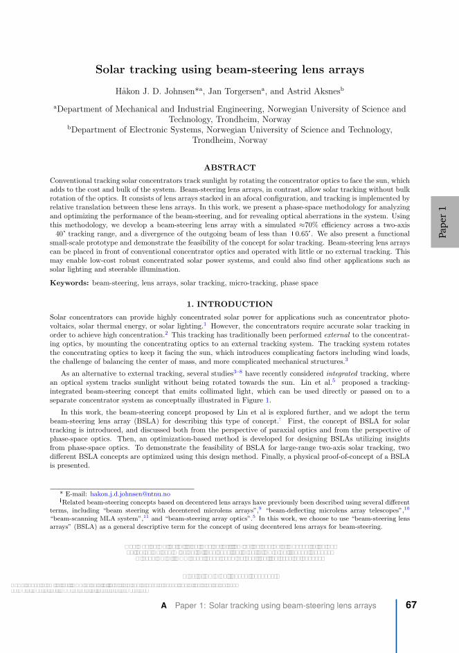
Solar tracking using beam-steering lens arrays
Hakon J. D. Johnsen*a, Jan Torgersena, and Astrid Aksnesb
aDepartment of Mechanical and Industrial Engineering, Norwegian University of Science andTechnology, Trondheim, Norway
bDepartment of Electronic Systems, Norwegian University of Science and Technology,Trondheim, Norway
ABSTRACT
Conventional tracking solar concentrators track sunlight by rotating the concentrator optics to face the sun, whichadds to the cost and bulk of the system. Beam-steering lens arrays, in contrast, allow solar tracking without bulkrotation of the optics. It consists of lens arrays stacked in an afocal configuration, and tracking is implemented byrelative translation between these lens arrays. In this work, we present a phase-space methodology for analyzingand optimizing the performance of the beam-steering, and for revealing optical aberrations in the system. Usingthis methodology, we develop a beam-steering lens array with a simulated ≈70% efficiency across a two-axis�40� tracking range, and a divergence of the outgoing beam of less than �0.65�. We also present a functionalsmall-scale prototype and demonstrate the feasibility of the concept for solar tracking. Beam-steering lens arrayscan be placed in front of conventional concentrator optics and operated with little or no external tracking. Thismay enable low-cost robust concentrated solar power systems, and could also find other applications such assolar lighting and steerable illumination.
Keywords: beam-steering, lens arrays, solar tracking, micro-tracking, phase space
1. INTRODUCTION
Solar concentrators can provide highly concentrated solar power for applications such as concentrator photo-voltaics, solar thermal energy, or solar lighting.1 However, the concentrators require accurate solar tracking inorder to achieve high concentration.2 This tracking has traditionally been performed external to the concentrat-ing optics, by mounting the concentrating optics to an external tracking system. The tracking system rotatesthe concentrating optics to keep it facing the sun, which introduces complicating factors including wind loads,the challenge of balancing the center of mass, and more complicated mechanical structures.3
As an alternative to external tracking, several studies3–8 have recently considered integrated tracking, wherean optical system tracks sunlight without being rotated towards the sun. Lin et al.5 proposed a tracking-integrated beam-steering concept that emits collimated light, which can be used directly or passed on to aseparate concentrator system as conceptually illustrated in Figure 1.
In this work, the beam-steering concept proposed by Lin et al is explored further, and we adopt the termbeam-steering lens array (BSLA) for describing this type of concept.� First, the concept of BSLA for solartracking is introduced, and discussed both from the perspective of paraxial optics and from the perspective ofphase-space optics. Then, an optimization-based method is developed for designing BSLAs utilizing insightsfrom phase-space optics. To demonstrate the feasibility of BSLA for large-range two-axis solar tracking, twodifferent BSLA concepts are optimized using this design method. Finally, a physical proof-of-concept of a BSLAis presented.
* E-mail: [email protected]�Related beam-steering concepts based on decentered lens arrays have previously been described using several different
terms, including “beam steering with decentered microlens arrays”,9 “beam-deflecting microlens array telescopes”,10
“beam-scanning MLA system”,11 and “beam-steering array optics”.5 In this work, we choose to use “beam-steering lensarrays” (BSLA) as a general descriptive term for the concept of using decentered lens arrays for beam-steering.
Nonimaging Optics: Efficient Design for Illumination and Solar Concentration XV,edited by Roland Winston, Eli Yablonovitch, Proc. of SPIE Vol. 10758, 1075805
© 2018 SPIE · CCC code: 0277-786X/18/$18 · doi: 10.1117/12.2320046
Proc. of SPIE Vol. 10758 1075805-1
Downloaded From: https://www.spiedigitallibrary.org/conference-proceedings-of-spie on 11/13/2018Terms of Use: https://www.spiedigitallibrary.org/terms-of-use
Pape
r1
A Paper 1: Solar tracking using beam-steering lens arrays 67

Beam-steering lens array
Concentrator
Receiver
Figure 1: Conceptual illustration of how a beam-steering lens array can be combined with conventional concen-trator optics.
2. BEAM-STEERING LENS ARRAYS
Δx
L1
L2
L1 L2
f1
f2
(a)
f1 f2
Δx
L1
L2
L1 L2
f1 f2
(b)
L1 Lf L2
L1 LfL2
f f
f f
(c)
Figure 2: Paraxial beam-steering lens array principle using (a) Galilean configuration, (b) Keplerian configura-tion, and (c) Keplerian configuration including a field lens.
A basic BSLA consists of a pair of lens arrays arranged in an afocal configuration, allowing beam-steeringby relative lateral translation of the two lens arrays as illustrated in Figure 2. This concept has previously beenproposed for steering of laser beams.9,11 Despite utilizing the same idea, there are some important differencesbetween these laser applications and applications for solar energy:
� For laser beam-steering, a BSLA receives a beam parallel to its optical axis and emits it at an angle.For solar energy applications, the BSLA must be operated in reverse, receiving a beam at an angle, andemitting it parallel to the optical axis, as first proposed by Lin et al.5
� When used for solar energy, the BSLA must be orders of magnitude larger than when used for laser beamsteering. This naturally also leads to larger lenslets.
� The coherence of laser light means that additional optics are required in order to allow for continuous laserbeam steering.11 This is not necessary for solar tracking, due to the reduced coherence of sunlight.
Proc. of SPIE Vol. 10758 1075805-2
Downloaded From: https://www.spiedigitallibrary.org/conference-proceedings-of-spie on 11/13/2018Terms of Use: https://www.spiedigitallibrary.org/terms-of-use
Pape
r1
68 Appendix A Full-text papers

� The beam-steering range for laser beam-steering is typically on the order of 5◦ to 15◦.11–13 For solartracking, much larger beam-steering angles are required.
Because of the large differences from previous laser applications, there is a need to re-think the concept anddevelop new design methods, which is the target of this work.
The idea behind this approach to beam-steering can be described both from the perspective of paraxial opticsand from the perspective of phase-space optics.
2.1 Paraxial optics
f1 f2
Δxmaxd θmax
L1
L2
(a)
f
Δxmaxd θmax
f
L1 Lf
L2
(b)
Figure 3: Geometry of a BSLA lenslet (a) without and (b) with a field lens, at maximum steering angle.
Figure 2a and Figure 2b show basic beam-steering lens arrays in Keplerian and Galilean configurations. Thelens arrays are separated by their combined focal lengths f1 + f2. The BSLA can track incoming sunlight atan incidence angle θ by translating the last lens array a distance ∆x such that the second lens array is alwaysaligned with the focused image of the sun from the first lens array:
∆x = f1 · tan θ. (1)
In order for all rays to reach the correct lens in the array L2, the second focal length must be smaller thanthe first, as illustrated in Figure 3a. This leads to an angular magnification factor M :
M =f1
f2= 1 + 2
f1
dtan θmax. (2)
Sunlight has an inherent divergence of ±0.27◦.14 In order to limit the increase of divergence behind theBSLA and allow concentrators with high concentration factors, it is desirable that the angular magnification ofthe system is low. With two paraxial lenses, we therefore face a trade-off between the tracking range θmax, andthe additional divergence caused by angular magnification.
One approach to reduce this angular magnification is to add a field lens Lf to the BSLA in the Keplerianconfiguration, as shown in Figure 2c. With this approach, identical focal lengths f and an angular magnificationof unity can be achieved.9 However, with a field lens, the maximum tracking angle is limited to θmax = arctan d
2f
as illustrated in Figure 3b.
2.2 Phase-space optics
A phase-space approach can be used to develop visual insight into the behavior and performance of a BSLA,and provides understandings that are useful in reducing the complexity of the design of such a system.
The trajectory of a ray in a geometrical optical system is determined by its position and direction. Theseparameters can be represented together in optical phase space, a space consisting of the linear dimensions aswell as direction cosines of the optical ray. Phase-space optics is used to prove a number of important resultsin nonimaging optics,2 and is also useful in visualizing the performance and aberrations of optical systems.15
Proc. of SPIE Vol. 10758 1075805-3
Downloaded From: https://www.spiedigitallibrary.org/conference-proceedings-of-spie on 11/13/2018Terms of Use: https://www.spiedigitallibrary.org/terms-of-use
Pape
r1
A Paper 1: Solar tracking using beam-steering lens arrays 69

For three-dimensional systems, four parameters are required to describe a ray-bundle crossing a surface - twodirectional parameters and two physical parameters. The phase-space representation of a three-dimensionaloptical system is therefore not very easy to visualize. However, much information about the system can beextracted from the two-dimensional counterpart, where ray-bundles crossing a surface can be described usingonly two parameters.15
Figure 4 shows the optical behavior of a paraxial BSLA from a phase-space perspective. At each indicatedsurface, ray-bundles from the whole tracking range are plotted in two-dimensional phase-space with their positionx, and direction p = n · sin θ. This illustrates the different transformations performed by the system: The lensesare used to convert a collimated beam with an angular offset into a focused ray-bundle with translational offset.This focused ray-bundle can then easily be tracked mechanically before being transformed back into a collimatedbeam.
(a)
(b)
Figure 4: (a) Simple two-dimensional BSLA without field lens. (b) Sketch of the phase-space transformationsperformed by a two-dimensional paraxial BSLA. An incoming collimated ray bundle has a certain offset indirection p. The focusing lens transforms the rays into a focused bundle with a certain offset in position x. Thetracker performs a coordinate transformation to center this position. Finally, the collimating lens transforms therays into a centered collimated beam.
Figure 4 indicates that the phase-space transformation performed by the focusing lens has very differentrequirements from the phase-space transformation performed by the collimating lens:
� The focusing transformation is heavily overdetermined. From each separate tracking angle, the focusinglens should transform the incoming ray-bundle into a ray-bundle with a consistent phase-space geometry.The design problem is therefore very similar to design problems in conventional imaging optics, with one
Proc. of SPIE Vol. 10758 1075805-4
Downloaded From: https://www.spiedigitallibrary.org/conference-proceedings-of-spie on 11/13/2018Terms of Use: https://www.spiedigitallibrary.org/terms-of-use
Pape
r1
70 Appendix A Full-text papers

important relaxation: the focused wavefronts should be consistent, but not necessarily spherical. Thisdifference is further discussed and illustrated below.
� The collimating transformation should transform a single ray-bundle into a narrow collimated ray-bundle.This is a variant of the bundle-coupling problem of Nonimaging Optics, and well known design methodssuch as the Simultaneous Multiple Surface (SMS) method can give optimal or close to optimal solutionsto this problem.2
(a)
(b)
Figure 5: (a) Simple two-dimensional BSLA with field lens. (b) Phase-space transformations by this BSLA.The two first lenses are spherical, which is visible in the spherical aberration at surface 2 and 3. This sphericalaberration is corrected by the final lens, which is aspherical.
Figure 5 shows phase-space plots of a real BSLA with a field lens, illustrating the difference between thefocusing (and field) lens in a BSLA and a conventional imaging system. For illustration purposes, the focusingand field lenses in this system are spherical, leading to significant spherical aberration. This spherical aberrationis visible as curved shapes in the second and third phase-space plots of Figure 5, and the lenses would thereforework poorly as an imaging system. As part of a BSLA however, the collimating lens is able to compensate forthe spherical aberration. This is the major distinction between an imaging lens and the focusing lens in a BSLA:The performance of an imaging system depends on how well rays from a single field of the input, p, are mappedonto a position, x. In other words, it depends on the edges to be vertical in phase-space plot 2 of Figure 5. Theperformance of a BSLA on the other hand, does not require focusing to a perfect point. Instead, performancedepends on the size of the total phase-space area to be collimated by the collimating lens. This area can bereduced by making ray-bundles from all the different incidence angles overlap as much as possible after tracking,as they do in phase-space plot 3 of Figure 5.
Proc. of SPIE Vol. 10758 1075805-5
Downloaded From: https://www.spiedigitallibrary.org/conference-proceedings-of-spie on 11/13/2018Terms of Use: https://www.spiedigitallibrary.org/terms-of-use
Pape
r1
A Paper 1: Solar tracking using beam-steering lens arrays 71

It is possible to estimate the performance of a BSLA directly without its collimating lens, by utilizing theproperties of the phase-space transformations. Assuming that the collimating transformation can be solved withclose to optimal performance, BSLA-performance can be predicted by evaluating the total occupied area in phase-space by all ray-bundles after tracking. The evaluated area is the etendue of the ray-bundles,15 and assumingoptimal etendue-conserving collimation, this directly gives the etendue and the divergence of the collimated beam.This concept will be used for subdividing and simplifying the optimization problem for designing a BSLA.
3. OPTIMIZATION OF BEAM-STEERING LENS ARRAY
An optimization approach is developed for designing a three-dimensional BSLA. Optimization methods aremore computationally expensive and less stable than direct solution methods, but they have the benefit thatthey readily handle overdetermined problems with the complexities of real-world systems such as wavelengthdependent effects and manufacturing constraints.
3.1 Practical considerations
In order to implement a BSLA with high efficiency over a large two-axis field of view, some modifications mustbe done to the basic principles in Figure 2:
� The field lens in Figure 2c improves performance, but limits the tracking range to θmax = arctan df. It can
either be removed, or it can be allowed to move as part of the tracking motion in order not to limit thesystem’s tracking range.
� For wide field of view, field curvature becomes significant, and planar tracking is not sufficient. Trackingis therefore allowed to follow a curved trajectory.
� For tight packing in a lens array, close-packed hexagonal lenses are used instead of circular lenses.
� The wide field of view and limited number of optical surfaces introduce large aberrations, which arecompensated for by using thick lenses and allowing each lens surface to have an aspherical profile.
3.2 Formulation of optimization problem
We will consider three main performance indicators for quantifying and evaluating the performance of a completeBSLA:
� Maximizing tracking range
� Maximizing efficiency
� Minimizing divergence
The design of a BSLA can be considered a multi-objective optimization problem, where a solution must befound that provides a reasonable trade-off between these three performance indicators. Improving one of theseindicators can be done at the cost of lower performance in the other indicators. For example increasing thetracking range will increase the off-axis optical aberrations, leading to increased divergence of the outgoing rays.Increasing the efficiency on the other hand imposes additional constraints on the system, leaving fewer degrees offreedom for handling the optical aberrations and decreasing divergence. Multi-objective optimization algorithmscan be used to find a set of Pareto optimal solutions for these types of problems,16 quantifying these trade-offsand allowing the designer to make an informed choice among the set of solutions. However, in order to limitthe scope of this work, the optimization problem is reduced to a single-objective optimization problem in thefollowing way:
� A sum scalarization16 is performed to combine the efficiency and divergence into a single objective function.
� The racking range is fixed to a single value. In the design examples in this work, the value of ±40◦ ischosen as an example of a relatively wide tracking range.
Proc. of SPIE Vol. 10758 1075805-6
Downloaded From: https://www.spiedigitallibrary.org/conference-proceedings-of-spie on 11/13/2018Terms of Use: https://www.spiedigitallibrary.org/terms-of-use
Pape
r1
72 Appendix A Full-text papers

A sum scalarization allows optimization using simpler single-objective optimization algorithms, and a solutionto the scalarized problem is also a solution to the original multi-objective problem.16 However, this approachhas the drawback that it gives only a single solution and therefore no information about the trade-off betweenthe different performance indicators. The result is the following optimization problem
min f (x) =
m�
i=1
�
w1
1
ηi (x)+ w2 (δθi (x))
2
�
(3)
such that gj (x) ≤ 0 (4)
where w1 and w2 are relative weights applied to the efficiency and divergence. ηi(x) is the simulated efficiencyfor a ray-traced grid of rays with incidence angle number i and optical system described by x. δθi (x) is thecorresponding RMS divergence half-angle for field number i. m separate incidence angles are evaluated acrossthe tracking range of the BSLA. gj (x) is a set of inequality constraints ensuring manufacturability, such asminimum and maximum thickness, and maximum lens curvature.
3.2.1 Separation of optimization procedure using phase-space optics
The optimization problem in Equations 3 and 4 can in theory be solved directly for the complete system,using ray-tracing simulations and a suitable optimization algorithm. However, it is a non-linear non-convexoptimization problem with many variables, with no guarantee of finding the global minimum.
In order to reduce the complexity of the optimization problem and to increase the chance of finding a globalminimum, the phase-space analysis from Section 2.2 can be utilized to subdivide the optimization problem. Thisgives the following final design process:
1. Optimize focusing lens (and field lens, if included). The optimization problem in Equations 3 and 4 issolved. ηi(x) and δθi (x) are estimated by evaluating the volume in phase-space occupied by the set ofbundles focused by the focusing (and field) lens. x contains only parameters varying the geometry of thefocusing (and field) lens. The analysis in Section 2.2 considered only two-dimensional systems, but thisvolume estimate is readily extended to three-dimensional systems by assuming rotational symmetry of thecollimating lens.
2. Optimize a collimating lens for the optimized focusing lens. The same optimization problem in Equations3 and 4 is solved, but now ηi(x) and δθi (x) are evaluated directly from ray-tracing results of the completesystem, and x contains only parameters for the geometry of the collimating lens. This step might also beperformed using a direct method such as the SMS method, bypassing the need for optimization in thisstep.
3. Refine the complete system by performing an optimization step where x contains all parameters for thecomplete system. This allows for any final improvements that were not achieved when optimizing sepa-rately due to inaccuracies in the phase-space model. For instance, the phase-space evaluation assumes arotationally symmetric system, while the lenses are actually hexagonal when closely packed in an array.Some small additional improvements can therefore be gained by this final optimization step, and step 1and 2 can be considered as a way to get a good initial starting point for this final optimization step.
4. DESIGN EXAMPLE
4.1 Methods
Two different systems were optimized using the optimization procedure outlined in Sections 3.2 & 3.2.1.
� One BSLA with three lens arrays: A focusing lens, a movable field lens, and a collimating lens. This waschosen in order to demonstrate how the benefits of a field lens can be extended to large tracking rangeswhen the field lens is allowed to move.
Proc. of SPIE Vol. 10758 1075805-7
Downloaded From: https://www.spiedigitallibrary.org/conference-proceedings-of-spie on 11/13/2018Terms of Use: https://www.spiedigitallibrary.org/terms-of-use
Pape
r1
A Paper 1: Solar tracking using beam-steering lens arrays 73

� One BSLA with only two lens arrays: A focusing lens and a collimating lens. This was chosen in order todemonstrate a BSLA without the mechanical complexity of the movable field lens.
Both BSLAs were simulated across the AM1.5D solar spectrum,17 with Poly(methyl methacrylate) (PMMA)as lens material, using a custom sequential three-dimensional ray-tracer. The ray-tracer was written in Pythonand accelerated using Numba.18 Optimization was performed using a combination of the Differential Evolution,Basinhopping and L-BFGS-B-algorithms available from SciPy.19
Table 1: Constraints used in optimization of BSLA. The dimensions of the system are scalable with the arbitraryscaling factor k.
Parameter Constraint
Semi-diameter of lenses 1.0 · k
Minimum thickness at thinnest point of lens 0.5 · k
Maximum thickness at thickest point of lens 2.0 · k
Minimum air gap between lenses 0.05 · k
Maximum air gap between lenses 2.0 · k
Minimum radius of curvature on lens 0.7 · k
Maximum aspect ratio of single surface 0.5
Fresnel reflections and dispersion were taken into account, while material absorption was ignored�. Hexagonallenses were used for all simulations to allow for close packing in a lens array. The divergence of outgoing lightwas estimated as a combination of divergence due to optical aberrations, and divergence due to magnification ofthe inherent divergence of sunlight.
The constraints from Table 1 were used to ensure reasonable, manufacturable designs. For the design witha field lens, the lateral translation of the two lens arrays were constrained to be proportional to each other,allowing linked control sharing the same mechanical actuator.
Plots of efficiency and divergence half-angle are created using ray-tracing of 80 000 random rays per incidenceangle, with random wavelengths according to the AM1.5D spectrum and random directions within the 0.27◦
divergence half-angle of sunlight. The plotted divergence half-angle is defined as the half-angle encircling 90%of the transmitted energy. The plotted efficiency takes into account Fresnel reflections, but does not considermaterial absorption or cosine projection loss.
4.2 Results and discussion
The resulting optimized design with a field lens is shown in Figure 6a, and the system without a field lens isshown in Figure 6b. The simulated optical performance under solar irradiation is shown in Figure 7. The systemwith a field lens has lower optical efficiency at low angles of incidence, due to the increased number of opticalsurfaces. However, at high incidence angles, it still surpasses the efficiency of the system without a field lens.
The additional divergence introduced by the BSLA requires the use of concentrator optics with higher ac-ceptance angle, decreasing the maximum achievable concentration ratio. However, the results in Figure 7 showthat by including a field lens, this final divergence half-angle can be kept at less than 0.65◦ across the trackingrange, which will still permit approximately 7800x concentration from an ideal concentrator.2
With increased angle of incidence, intensity of sunlight received by a flat stationary receiver decreases dueto the cosine projection effect. Even if the lens design is improved with a higher acceptance angle, powerwill therefore be low for high angles of incidence, and some amount of external tracking might be required for
�Material absorption depends on the physical dimensions of the BSLA, which are not fixed in these design examples
Proc. of SPIE Vol. 10758 1075805-8
Downloaded From: https://www.spiedigitallibrary.org/conference-proceedings-of-spie on 11/13/2018Terms of Use: https://www.spiedigitallibrary.org/terms-of-use
Pape
r1
74 Appendix A Full-text papers

(a) (b)
Figure 6: Ray-traced sketch of optimized system (a) with, and (b) without field lens.
Figure 7: Simulated optical performance with and without field lens. Using a field lens reduces divergencesignificantly at the cost of increased mechanical complexity. Inherent divergence of natural sunlight is includedfor reference.
efficient full-day operation. Yet, we conclude that the use of beam-steering lens arrays still significantly reducesthe requirements for this external tracking.
Figure 8 shows two-dimensional phase-space plots of the optimized systems. The phase-space plots are gen-erated at the focal point after tracking. As discussed in Section 2.2, performance of the focusing transformationdepends on how well the ray-bundles from one specific wavelength and angle of incidence overlap with all otherray bundles. For the BSLA without field lens (Figure 8b) we can see that the optimization algorithm has chosena focusing lens where the shape of the total occupied area in phase-space is strongly nonlinear, but this is nota problem for the collimating lens. We can also see that ray-bundles from different wavelengths don’t overlapvery well, indicating significant chromatic aberration. For the BSLA with field lens, in Figure 8a, we see thatthe field lens is able to significantly improve the overlap of the ray-bundles, especially the overlap in momentum.In addition, the ray-bundles for different wavelengths overlap more. This leads to the reduced divergence aftercollimation and improved performance.
Proc. of SPIE Vol. 10758 1075805-9
Downloaded From: https://www.spiedigitallibrary.org/conference-proceedings-of-spie on 11/13/2018Terms of Use: https://www.spiedigitallibrary.org/terms-of-use
Pape
r1
A Paper 1: Solar tracking using beam-steering lens arrays 75

(a)
(b)
Figure 8: Two-dimensional phase-space plots at focal point. For system (a) with, and (b) without field lens.
5. PROOF-OF-CONCEPT
A physical and functional proof-of-concept with automatic tracking has been created using a previously opti-mized BSLA design. The design was created using an earlier optimization technique, with lower performance.20
Despite this lower performance, the proof-of-concept serves to demonstrate the feasibility of creating a complete,functional BSLA. As an example use case for this proof-of-concept, the BSLA has been attached to an off-axisparabolic reflector that illuminates a target from the underside. This specific configuration is a scaled-downversion of a solar cooking concept using BSLA.
5.1 Manufacturing and testing methods
Compression molds for the lens arrays were machined in aluminum on an in-house Computer Numerical Control(CNC) milling machine, due to the lack of access to high-precision optical manufacturing equipment. Thesemolds were used for compression molding of PMMA plates.
The tracking motion is actuated using SG-92R micro servos and controlled from an Arduino Nano devel-opment board. The system uses a combination of open- and closed-loop control, and both control loops havebeen implemented with low-cost photocells: Approximate solar position is detected using a set of four inclinedphotocells, each inclined ±40◦ from the front plane about their respective axes. The four photocells sense differ-ent relative brightness values due to their different angle towards the sun and the cosine projection loss. Fromthis data, the incidence angle of the sunlight can be inferred. The microcontroller orients the BSLA to thisapproximate angle. Secondly, the tracking is fine-tuned by diverting a small section of the input aperture to aset of photocells that measure tracking error, and a closed control loop is implemented in order to minimize thistracking error.
An image analysis setup was used for testing the optical performance of the completed BSLA, as reported inearlier work.20
Proc. of SPIE Vol. 10758 1075805-10
Downloaded From: https://www.spiedigitallibrary.org/conference-proceedings-of-spie on 11/13/2018Terms of Use: https://www.spiedigitallibrary.org/terms-of-use
Pape
r1
76 Appendix A Full-text papers

(a) (b)
Figure 9: (a) 3D model of Proof-of-concept with concentrator (b) Video of proof-of-concept tested outside in thesun. http://dx.doi.org/10.1117/12.2320046.1
5.2 Results
A 3D model of the proof-of-concept attached to a concentrator is shown in Figure 9a, and the device is shownoutside in the sun in Figure 9b.
Figure 10 shows the measured optical performance of the proof-of-concept BSLA, compared to simulatedvalues. The results show ≈ 10% reduced efficiency compared to the simulated values, and approximately a doubling of divergence compared to simulation. The high divergence is likely a result of a waviness in the surface of the lens array, due to the low precision of the mold manufacturing process. With improved mold manufacturing and corresponding increased surface quality, future prototypes are expected to better follow the predicted performance.
Figure 10: Simulated and measured efficiency and divergence of the proof-of-concept over its field of view.
6. OUTLOOK AND CONCLUSIONS
We have shown that beam-steering lens arrays can be used to track and redirect sunlight with low losses overa two-axis �40� tracking range, and we have presented an optimization-based design method for designing suchsystems. We have also demonstrated a physical proof-of-concept, demonstrating its practicality in the real world.Further work will involve exploration of the solution space, by mapping the trade-off between tracking range,efficiency, and divergence, as well as the impact of the selected manufacturing constraints. We are also planningto create a new proof-of-concept according to updated BSLA designs, and with improved manufacturing methods.
Proc. of SPIE Vol. 10758 1075805-11
Downloaded From: https://www.spiedigitallibrary.org/conference-proceedings-of-spie on 11/13/2018Terms of Use: https://www.spiedigitallibrary.org/terms-of-use
Pape
r1
A Paper 1: Solar tracking using beam-steering lens arrays 77

Beam-steering lens arrays can be made from common low-cost materials such as PMMA, and they can becompatible with high-volume production techniques such as injection molding or hot embossing. They maytherefore foster the development of low-cost, small-scale solar energy systems for a number of applicationsincluding solar cooking, small-scale solar thermal processing, solar water heating, concentrator photovoltaics andsolar lighting.
REFERENCES
[1] Xie, W. T., Dai, Y. J., Wang, R. Z., and Sumathy, K., “Concentrated solar energy applications using Fresnellenses: A review,” Renewable and Sustainable Energy Reviews 15, 2588–2606 (Aug. 2011).
[2] Winston, R., Minano, J. C., Benitez, P. G., contributions by Narkis Shatz and John C. Bortz, W., andBortz, J. C., [Nonimaging Optics ], Saint Louis : Elsevier Science, Saint Louis (2005).
[3] Apostoleris, H., Stefancich, M., and Chiesa, M., “Tracking-integrated systems for concentrating photo-voltaics,” Nature Energy 1, 16018 (Mar. 2016).
[4] Grede, A. J., Price, J. S., and Giebink, N. C., “Fundamental and practical limits of planar tracking solarconcentrators,” Optics Express 24, A1635–A1646 (Dec. 2016).
[5] Lin, W., Benitez, P., and Minano, J. C., “Beam-steering array optics designs with the SMS method,” Proc.SPIE 8485, 848505–848505–7 (2012).
[6] Campbell, R. and Machado, M., “LOW cost CPV = Embedded CPV with internal tracker,” in [2010 35thIEEE Photovoltaic Specialists Conference (PVSC) ], 003003–003007 (June 2010).
[7] Duerr, F., Meuret, Y., and Thienpont, H., “Tailored free-form optics with movement to integrate trackingin concentrating photovoltaics,” Optics Express 21, A401–A411 (May 2013).
[8] Hallas, J. M., Baker, K. A., Karp, J. H., Tremblay, E. J., and Ford, J. E., “Two-axis solar trackingaccomplished through small lateral translations,” Applied Optics 51, 6117 (Sept. 2012).
[9] Watson, E. A., “Analysis of beam steering with decentered microlens arrays,” Optical Engineering 32(11),2665–2670 (1993).
[10] Duparre, J., Radtke, D., and Dannberg, P., “Implementation of field lens arrays in beam-deflecting microlensarray telescopes,” Applied Optics 43, 4854–4861 (Sept. 2004).
[11] Akatay, A., Ataman, C., and Urey, H., “High-resolution beam steering using microlens arrays,” OpticsLetters 31, 2861–2863 (Oct. 2006).
[12] Bourderionnet, J., Rungenhagen, M., Dolfi, D., and Tholl, H. D., “Continuous laser beam steering withmicro-optical arrays: Experimental results,” Proc. SPIE 7113, 71130Z, International Society for Optics andPhotonics (Oct. 2008).
[13] Xiang, J., Wu, N., Zhang, J., and Wu, L., “Design of driving and control system based on Voice CoilActuation for linear motion of micro-lens array,” Proc. SPIE 7133, 713330, International Society for Opticsand Photonics (Jan. 2009).
[14] Kalogirou, S. A., [Solar Energy Engineering: Processes and Systems ], Academic Press (Oct. 2013).
[15] Herkommer, A. M., “Phase space optics: An alternate approach to freeform optical systems,” Proc. SPIE 53,031304 (Dec. 2013).
[16] Pardalos, P. M., Zilinskas, A., and Zilinskas, J., [Non-Convex Multi-Objective Optimization ], Springer Op-timization and Its Applications, Springer International Publishing (2017).
[17] Renewable Resource Data Center, “Solar Spectral Irradiance: Air Mass 1.5.”https://rredc.nrel.gov/solar/spectra/am1.5/.
[18] Lam, S. K., Pitrou, A., and Seibert, S., “Numba: A LLVM-based Python JIT Compiler,” in [Proceedingsof the Second Workshop on the LLVM Compiler Infrastructure in HPC ], LLVM ’15, 7:1–7:6, ACM, NewYork, NY, USA (2015).
[19] Jones, E., Oliphant, T., Peterson, P., and others, “SciPy: Open source scientific tools for Python,” (2001).
[20] Johnsen, H. J. D., “Novel Low Cost Solar Thermal Energy Concepts for Developing Countries,” NTNU(2017).
Proc. of SPIE Vol. 10758 1075805-12
Downloaded From: https://www.spiedigitallibrary.org/conference-proceedings-of-spie on 11/13/2018Terms of Use: https://www.spiedigitallibrary.org/terms-of-use
Pape
r1
78 Appendix A Full-text papers

Paper 2: High-concentration wide-angletracking integration with stacked lens arrays
Pape
r2

Pape
r2
80 Appendix A Full-text papers

High-Concentration Wide-Angle Tracking Integration with Stacked Lens Arrays
Håkon Jarand Dugstad Johnsen1, a), Jan Torgersen1, and Astrid Aksnes2
1 Norwegian University of Science and Technology, Department of Mechanical and Industrial Engineering, Richard Birkelands Vei 2b, Trondheim, Norway
2 Norwegian University of Science and Technology, Department of Electronic Systems, O.S. Bragstads plass 2b, Trondheim, Norway
a) Corresponding author: [email protected]
Abstract. Tracking-integration can reduce or eliminate the need for external solar tracking in CPV (concentrator photovoltaics). Previous research has shown how tracking-integrated systems can achieve high concentration ratios, wide tracking ranges, and compatibility with low-cost high-volume manufacturing methods. However, to our knowledge, no existing concept has demonstrated high performance in all of these objectives at the same time. We show how a numerical optimization-based design method can be used to develop high-performance tracking-integrated configurations. We then present a configuration maintaining an approximately 5000x geometric concentration ratio across a two-axis ±60° tracking range, while also being compatible with low-cost manufacturing processes. By significantly increasing the achievable concentration ratio of low-cost tracking integrated systems, these systems may improve the competitiveness for concentrator photovoltaics. This can also lead to new applications such as high efficiency rooftop-mountable or vehicle-mountable CPV.
INTRODUCTION
Concentrator photovoltaics (CPV) promises improved efficiency compared to flat-panel Silicon photovoltaics [1], but this requires highly accurate solar tracking. Solar tracking is usually implemented using an external dual-axis tracking system, which adds to the bulk and cost of the installation. The large mechanical size can also make these trackers unsuitable for small-scale installations such as rooftop or vehicle-mountable CPV.
Tracking-integrated concentrator-schemes have been proposed as a way to mitigate this problem by reducing or removing the need for external solar trackers [2]. Kotsidas et al. proposed a system where an array of solar cells is moved relative to a stationary lens array in order to track the sun [3], and Hallas et al. proposed a similar system where an array of waveguide coupling features are moved relative to a stationary lens array [4]. Duerr et al. proposed a system where a pair of lens arrays are moved relative to each other to concentrate sunlight onto a moving lens array [5]. Price et al. proposed a system where a catadioptric optical stack creates a very flat image plane, and solar tracking is implementing by moving an array of microcells in this image plane [6].
In this work, we present an optimization-based design method for designing tracking-integrated CPV systems, and use this method to combine the novel catadioptric stack proposed by Price et al. with the idea of relative motion between lens arrays as proposed by Duerr et al. These new configurations achieve concentration ratios on the order of 5000x across a ±60° tracking range.
DESIGN METHOD
A tracking-integrated CPV concentrator should concentrate incident solar radiation with (1) the highest possible efficiency, (2) across the largest possible tracking range, and (3) onto the smallest possible surface of a PV cell. The
15th International Conference on Concentrator Photovoltaic Systems (CPV-15)AIP Conf. Proc. 2149, 070005-1–070005-6; https://doi.org/10.1063/1.5124204
Published by AIP Publishing. 978-0-7354-1894-3/$30.00
070005-1
Pape
r2
A Paper 2: High-concentration wide-angle tracking integrationwith stacked lens arrays
81
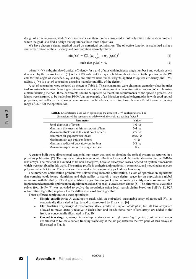
design of a tracking-integrated CPV concentrator can therefore be considered a multi-objective optimization problem where the goal is to find a design that optimizes these three objectives.
We have chosen a design method based on numerical optimization. The objective function is scalarized using a sum scalarization of the efficiency and concentration ratio objectives:
min ∑ (1)
suchthat 0, (2)
where is the simulated optical efficiency for a grid of rays with incidence angle number and optical system described by the parameters x. is the RMS radius of the rays in field number relative to the position of the PV cell for this angle of incidence. and are relative hand-tuned weights applied to optical efficiency and RMS radius. is a set of constraints ensuring manufacturability of the design.
A set of constraints were selected as shown in Table 1. These constraints were chosen as example values in order to demonstrate how manufacturing requirements can be taken into account in the optimization process. When choosing a manufacturing method, these constraints should be updated to match the requirements of the specific process. All lenses were assumed to be made from PMMA as an example of an injection-moldable thermoplastic with good optical properties, and reflective lens arrays were assumed to be silver coated. We have chosen a fixed two-axis tracking range of ±60° for the optimization.
TABLE 1. Constraints used when optimizing the different CPV configurations. The dimensions of the system are scalable with the arbitrary scaling factor .
Parameter Value
Semi-diameter of lenses 1.0 ⋅ Minimum thickness at thinnest point of lens 0.4 ⋅ Maximum thickness at thickest point of lens 2.5 ⋅ Minimum air gap between lenses 0.05 ⋅ Maximum air gap between lenses 4 ⋅ Minimum radius of curvature on the lens 0.5 ⋅ Maximum aspect ratio of a single surface 0.5
A custom-built three-dimensional sequential ray-tracer was used to simulate the optical system, as reported in a previous publication [7]. The ray-tracer takes into account reflection losses and chromatic aberration in the PMMA lens arrays. The material is assumed to be non-absorptive, because absorption losses depend on system dimensions which were not fixed in this work. The surface profile is aspheric and rotationally symmetric, and modelled as an even polynomial with 4 terms. The lenses were assumed to be hexagonally packed in a lens array.
The numerical optimization problem was solved using memetic optimization, a class of optimization algorithms that combine evolutionary algorithms and their ability to search a large design space for an approximate global minimum, with the ability of local gradient-based algorithms to quickly and accurately identify a local minimum. We implemented a memetic optimization algorithm based on Qin et al.’s local search chains [8]. The differential evolution solver from SciPy [9] was extended to evolve the population using local search chains based on SciPy’s SLSQP optimization algorithm in parallel to the differential evolution algorithm.
Three different configurations were optimized: Simple catadioptric: A catadioptric stack with an embedded translatable array of microcell PV, as
conceptually illustrated in Fig. 1a and first proposed by Price et al. [6] Flat tracking trajectory: A catadioptric stack similar to simple catadioptric, but all lens arrays are
allowed to move laterally relative to each other, and an additional pair of lens arrays are added to thefront, as conceptually illustrated in Fig. 1b.
Curved tracking trajectory: A catadioptric stack similar to flat tracking trajectory, but the lens arraysare allowed to follow a curved tracking trajectory at the air gap between the two pairs of lens arrays asillustrated in Fig. 1c.
070005-2
Pape
r2
82 Appendix A Full-text papers

(a) (b) (c)
FIGURE 1. Conceptual illustration of the three different CPV-configurations that were optimized: Simple catadioptric (a), flat tracking trajectory (b), and curved tracking trajectory (c). In each configuration, the lens stacks are assumed to be arranged in
a hexagonally packed lens array.
OPTIMIZATION RESULTS
Figure 2-4 show ray-traced drawings of the optimized CPV-designs after 9000 iterations of differential evolution.
(a) (b)
FIGURE 2. Optimized simple catadioptric CPV-system at 0° (a), and 60° (b) angle of incidence.
(a) (b)
FIGURE 3. Optimized CPV-system with flat tracking trajectory at 0° (a), and 60° (b) angle of incidence.
070005-3
Pape
r2
A Paper 2: High-concentration wide-angle tracking integrationwith stacked lens arrays
83

(a) (b)
FIGURE 4. Optimized CPV-system with curved tracking trajectory at 0° (a), and 60° (b) angle of incidence.
A more comprehensive Monte-Carlo simulation was performed on the optimized systems, quantifying optical
efficiency and geometric concentration ratio as a function of angle of incidence. We define optical efficiency
where is total energy in the rays entering the system for a specific angle of incidence, and is the energy in the
rays arriving on the receiver plane. We define geometric concentration ratio as where is the hexagonal
area of a lenslet, and is defined as the smallest area of a circular receiver intercepting 90% of the transmitted energy for the given angle of incidence. This definition allows quantifying how the concentrating abilities of the system varies with angle of incidence. In a physical implementation, a fixed receiver size would be chosen.
For each angle of incidence, 100 000 rays were sampled with random wavelengths according to the AM1.5D solar spectrum, random directions within the 0.27° divergence half-angle of sunlight, and random positions within the hexagonal aperture of the first lens. The results from this Monte-Carlo simulation are shown in Fig. 5.
The simulated performance of the simple catadioptric configuration gives a geometric concentration ratio >400x and optical efficiency >90%. This is comparable to the results published by Price et al [6], and the small variations are mainly because our work assumes a circular receiver when estimating concentration ratio.
The geometric concentration ratio is increased from approximately 400x to approximately 2000x when adding an additional pair of lens arrays to the system in the configuration shown in Fig. 1b. The concentration ratio is further increased to approximately 5000x if the lens arrays are allowed to follow a curved tracking trajectory as illustrated in Fig. 1c. The improved concentration ratio comes at the cost of reduced optical efficiency due to reflection losses, but these reflection losses can possibly be reduced without significant added cost using anti-reflective coatings or anti-reflective surface nanostructures [10].
The improved concentration ratio also introduces additional mechanical complexity with several lens arrays moving relative to each other. However, the translation of the different lens arrays is constrained to be proportional to each other so that they can share the same mechanical actuators, and the increased complexity might be justified by the significant improvement to concentration ratio. The designs are compatible with high-volume manufacturing techniques, such as injection molding or hot embossing by being relatively thin and made from commonly available thermoplastics such as PMMA.
The reported concentration ratios are very high, and much higher than in conventional CPV systems. We believe that the very high simulated concentration ratio is explained by a combination of factors. First, the concentration happens inside a dielectric, which inherently increases the thermodynamic limit to concentration by a factor where n is the refractive index of the dielectric. Second, the largest contributor to optical power in the system is the reflective lens array, which does not suffer for chromatic aberration unlike refractive lenses. Third, the system is assumed to be able to track the sun exactly, with an acceptance angle just large enough to fit the angular extent of the solar disc. This final assumption is made because each module can track the sun individually using a closed control loop, eliminating tracking errors from mounting the module to an external tracer, as well as tracking errors due to flexing of this external tracker.
Manufacturing tolerances are not taken into account in these simulations. It is likely that this will limit somewhat the ratio achieved in a physical implementation. The reported concentration ratios may also be too high for a PV cell to handle. However, we believe that this work demonstrates how it is possible to design tracking-integrated optical
070005-4
Pape
r2
84 Appendix A Full-text papers

systems where optical aberrations are not the limiting factor to system performance, and that it can motivate a further search towards tracking-integrated configurations with an optimal trade-off between performance and complexity.
FIGURE 5. Simulated optical efficiency and geometric concentration ratio across tracking range for the optimized CPV configurations. The performance is simulated using Monte Carlo ray-tracking, taking into account reflection losses, chromatic
aberration in the PMMA lens arrays, and the angular divergence of sunlight. The material is assumed to be non-absorptive.
CONCLUSIONS
We have presented an optimization-based design method for tracking-integrated CPV concentrator, and demonstrated how this method can be used to develop new and improved concentrators. Using this design method, we demonstrated new configurations for tracking-integrated CPV concentrators with improved optical performance, including a concentrating achieving a geometric concentration ratio of 5000x across a two-axis ±60° tracking range.
By significantly increasing the achievable concentration ratio of low-cost tracking integrated systems, these systems may improve the competitiveness for concentrator photovoltaics, and can also motivate the further search for new and promising concentrator configurations. The improved performance might enable new applications such as high efficiency rooftop-mountable or vehicle-mountable CPV. The presented design method can take into account the requirements of a specific application and manufacturing method, and can therefore be used to develop tailored CPV solutions optimized for specific use-cases and applications.
REFERENCES
1. M. A. Green, Y. Hishikawa, E. D. Dunlop, D. H. Levi, J. Hohl‐Ebinger, M. Yoshita, and A. W. Y. Ho‐Baillie,"Solar cell efficiency tables (Version 53)," Prog. Photovolt. Res. Appl. 27, 3–12 (2019).
2. H. Apostoleris, M. Stefancich, and M. Chiesa, "Tracking-integrated systems for concentrating photovoltaics,"Nat. Energy 1, 16018 (2016).
3. P. Kotsidas, E. Chatzi, and V. Modi, "Stationary nonimaging lenses for solar concentration," Appl. Opt. 49, 5183–5191 (2010).
4. J. M. Hallas, K. A. Baker, J. H. Karp, E. J. Tremblay, and J. E. Ford, "Two-axis solar tracking accomplishedthrough small lateral translations," Appl. Opt. 51, 6117 (2012).
5. F. Duerr, Y. Meuret, and H. Thienpont, "Tailored free-form optics with movement to integrate tracking inconcentrating photovoltaics," Opt. Express 21, A401–A411 (2013).
6. J. S. Price, X. Sheng, B. M. Meulblok, J. A. Rogers, and N. C. Giebink, "Wide-angle planar microtracking forquasi-static microcell concentrating photovoltaics," Nat. Commun. 6, 6223 (2015).
7. H. J. D. Johnsen, J. Torgersen, and A. Aksnes, "Solar tracking using beam-steering lens arrays," in NonimagingOptics: Efficient Design for Illumination and Solar Concentration XV (International Society for Optics andPhotonics, 2018), Vol. 10758, p. 1075805.
070005-5
Pape
r2
A Paper 2: High-concentration wide-angle tracking integrationwith stacked lens arrays
85

8. A. K. Qin, K. Tang, H. Pan, and S. Xia, "Self-adaptive differential evolution with local search chains for real-parameter single-objective optimization," in 2014 IEEE Congress on Evolutionary Computation (CEC) (IEEE,2014), pp. 467–474.
9. E. Jones, T. Oliphant, P. Peterson, and others, "SciPy: Open source scientific tools for Python," (2001). 10. C.-J. Ting, M.-C. Huang, H.-Y. Tsai, C.-P. Chou, and C.-C. Fu, "Low cost fabrication of the large-area anti-
reflection films from polymer by nanoimprint/hot-embossing technology," Nanotechnology 19, 205301 (2008).
070005-6
Pape
r2
86 Appendix A Full-text papers

Paper 3: Pushing the limits of beam-steeringlens arrays
Pape
r3

Pape
r3
88 Appendix A Full-text papers

Pushing the limits of beam-steering lens arraysHåkon J. D. Johnsen*a, Astrid Aksnesb, and Jan Torgersena
aDepartment of Mechanical and Industrial Engineering, Norwegian University of Science andTechnology, Trondheim, Norway
bDepartment of Electronic Systems, Norwegian University of Science and Technology,Trondheim, Norway
ABSTRACTAn essential part of a concentrated solar power system is the solar tracker. Tracking is usually implemented byrotating the entire optical system to follow the sun, adding to the bulk and complexity of the system. Beam-steering lens arrays, on the other hand, enable solar tracking using millimeter-scale relative translation betweena set of lens arrays stacked in an afocal configuration. We present an approach for designing and comparingbeam-steering lens arrays based on multi-objective optimization, where the objective is to maximize efficiency,minimize divergence, and minimize cost/complexity. We then use this approach to develop new configurationswith improved performance compared to previously reported results. As an example of a design suitable forhigh-concentration applications, we present a system consisting of four single-sided lens arrays that can trackthe sun with a yearly average efficiency of 74.4% into an exit-cone with divergence half-angle less than ±1◦.We also present a simplified system consisting of three single-sided lens arrays, which can be implemented withless mechanical complexity and potentially lower cost. This simplified system achieves 74.6% efficiency and adivergence half-angle of less than ±2.2◦, and might be relevant for low or medium concentration applications.We believe that these results demonstrate the previously untapped potential of beam-steering lens arrays. Ifsuch designs are successfully manufactured, they may become an attractive alternative to conventional externalsolar trackers for a range of solar energy applications.
Keywords: beam-steering, lens arrays, solar tracking, micro-tracking
1 INTRODUCTIONSolar concentrators can provide highly concentrated solar power for applications such as concentrator photo-voltaics, solar thermal energy, or solar lighting.1 The concentrators require accurate solar tracking in order toachieve high concentration,2 which is usually performed by rotating the concentrator to face the sun. Recentwork, however, has considered the use of tracking-integrated systems, which can track the sun without beingrotated by an external solar tracker.3
One approach to tracking-integration is the concept of beam-steering, where a tracking-integrated systememits collimated light, which can then be concentrated in a separate concentrator, as conceptually illustrated inFigure 1a. This approach enables the same beam-steering system to be used for several different applicationsand allows the design of the concentrator optics to be independent of the design of the tracking optics. Severalbeam-steering concepts have been proposed for solar tracking, including electrowetting to change the angle ofthe interface between two liquids with different refractive indices,4 microfluidic beam-steering arrays,5 rotatingprism arrays,6 liquid crystals controlled by electric fields,7 rotating off-axis Fresnel lenses,8 and beam-steeringlens arrays.9,10
A beam-steering lens array consists of a set of lens arrays stacked in an afocal configuration that can redirectsunlight by relative movement between these lens arrays, as first proposed for solar tracking by Lin et al.9 Thecore principle is illustrated in Figure 1b.
In this work, we investigate the achievable performance of beam-steering lens arrays. We develop a newapproach for comparing different beam-steering lens array configurations and use it to optimize new configurationswith improved performance compared to previously reported results.
* E-mail: [email protected]
Nonimaging Optics: Efficient Design for Illumination and Solar Concentration XVI, edited by Roland Winston, Eli Yablonovitch, Proc. of SPIE Vol. 11120, 111200B · © 2019 SPIE
CCC code: 0277-786X/19/$21 · doi: 10.1117/12.2528751
Proc. of SPIE Vol. 11120 111200B-1Downloaded From: https://www.spiedigitallibrary.org/conference-proceedings-of-spie on 22 Nov 2019Terms of Use: https://www.spiedigitallibrary.org/terms-of-use
Pape
r3
A Paper 3: Pushing the limits of beam-steering lens arrays 89

Concentrator
Receiver
Beam-steering system
Incoming rays
(a) �E�
Figure 1: (a) Conceptual illustration of how a beam-steering system can be combined with conventional concentratoroptics. (b) Example of a beam-steering lens array: An afocal stack of lens arrays, which redirects sunlight utilizingrelative movement between these lens arrays.
2 CLASSIFYING DIFFERENT CONFIGURATIONSWith the development of new types of beam-steering lens arrays, we believe that it will be useful to have a wayof classifying different designs. Previous beam-steering lens array designs have utilized both single-sided9 anddouble-sided10 lens arrays, with relative lateral11 or curved9 tracking motion, and with both two,9 and three12
lens arrays stacked together. In order to readily specify, compare, and evaluate different classes of designs, itcan be useful to designate specific symbols for each of the components in a beam-steering lens array. Specificconfigurations of beam-steering lens arrays can then be described using a sequence of these symbols.
In this work, we use the set of symbols shown in Table 1.
Table 1: Proposed symbols for classifying different beam-steering lens array configurations. Symbols are represented inUnicode and can be copied and pasted as text into any software that supports Unicode.
Symbol∗ Meaning
◀ Single-sided lens array with the flat side on the right.▶ Single-sided lens array with the flat side on the left.◆ Double-sided lens array↓ Air-gap between lens arrays supporting a flat, lateral tracking
trajectory.⤸ Air-gap between lens arrays supporting a curved tracking
trajectory.◀ ▶ A pair of single-sided lens arrays placed back-to-back, with
index-matched lubricating oil between them supporting relativelateral translation between the lens arrays.
The symbols from Table 1 can be used to classify both existing and new beam-steering lens array configura-tions. For instance:
• Lin et al., 2012:9 ◀⤸▶• Watson, 199314 (for steering of laser beams): ◆↓◆and ◆↓◆ ◆• Johnsen et al., 2018:10 ◆⤸◆and ◀⤸◆⤸◆∗The symbols are represented by the following Unicode13 code-points: ◀=U+25C0, ▶=U+25B6, ◆=U+25C6,
↓=U+2193, ⤸=U+2938, ◀ ▶=U+25C0 U+200A U+25B6
Proc. of SPIE Vol. 11120 111200B-2Downloaded From: https://www.spiedigitallibrary.org/conference-proceedings-of-spie on 22 Nov 2019Terms of Use: https://www.spiedigitallibrary.org/terms-of-use
Pape
r3
90 Appendix A Full-text papers

3 DESIGN METHODWe have utilized a design method based on ray-tracing and numerical optimization for designing and comparingdifferent beam-steering lens array configurations. In this section, we describe this design method and specify theconditions for the optimization results reported in this paper.
3.1 Formulation of the optimization problemWe consider three main performance objectives for evaluating the performance of a complete beam-steering lensarray:
• Maximizing the efficiency in redirecting sunlight.
• Minimizing the divergence of outgoing sunlight
• Minimizing the cost/complexity
The design of a beam-steering lens array can, therefore, be considered a multi-objective optimization problem.An optimal solution must provide a reasonable trade-off between these objectives. Multi-objective optimizationproblems can be solved by finding a set of Pareto optimal solutions: solutions where one objective cannotbe improved without degrading another objective. In this way, the trade-off between objectives is quantified,allowing a designer to make an informed choice among the set of solutions.15
Efficiency and divergence can be quantified as continuous objective values, allowing a multi-objective opti-mization algorithm to map out the Pareto front between these objectives. Cost/complexity, on the other hand, isdifficult to quantify and depends on several different factors. We have, therefore, not tried to quantify complexitydirectly. Instead, we optimized several different configurations with different levels of complexity.
We formulated the following optimization problem:
min f (x, θmax) = (1− η (x, θmax) , θmax)T (1)
such that gj (x) ≤ 0, (2)
where θmax is the allowed divergence of outgoing sunlight, and η(x, θmax) is the average yearly opticalefficiency of the optical system x. gj (x) is a set of inequality constraints, ensuring manufacturability.
3.2 Estimating average optical efficiencyAverage optical efficiency can be defined as the fraction of yearly direct irradiation successfully redirected in thedesired direction:
η (x, θmax) =Eout (x, θmax)
Ein, (3)
where Ein is the yearly direct irradiation received by the beam-steering lens array surface, and Eout (x, θmax)is the yearly irradiation successfully redirected within the permitted exit cone.
This average efficiency can be estimated by integrating across all angles of incidence:
η (x, θmax) =
∫ π
0
e (ϕ) · η (x, θmax, ϕ) dϕ, (4)
where e (ϕ) =Ein,ϕ(ϕ)
Einis the normalized angular distribution of irradiation received by the beam-steering lens
array in its installation location. η (x, θmax, ϕ) is the optical efficiency of the beam-steering lens for an opticalsystem x, a maximum divergence of outgoing sunlight θmax and an angle of incidence ϕ.
Proc. of SPIE Vol. 11120 111200B-3Downloaded From: https://www.spiedigitallibrary.org/conference-proceedings-of-spie on 22 Nov 2019Terms of Use: https://www.spiedigitallibrary.org/terms-of-use
Pape
r3
A Paper 3: Pushing the limits of beam-steering lens arrays 91

In this work, we consider the beam-steering lens arrays to have a fixed orientation, tilted towards the equatorwith an angle equal to the latitude of the installation location as illustrated in Figure 2a. As noted by Ito et al.,this orientation gives a peak in irradiation distribution at 22◦−25◦ angle of incidence, irrespective of installationlocation.16 We consider the beam-steering lens arrays optimized in this paper to be installed at a latitude of40◦. We simulate the angular distribution of solar irradiation using Meinel and Meinel’s air mass attenuationmodel17 and assuming that cloud cover is not correlated to time of day or time of year. The resulting normalizedirradiation distribution is shown in Figure 2b. When planning a physical realization of such a system, the realmeteorological conditions of the desired installation location should be used.
It is worth noting that η in Equation 3 is defined relative to the irradiation reaching the front surface ofthe beam-steering lens array as it is mounted in its assumed orientation. Cosine projection loss is therefore notincluded in this average efficiency, and will give an additional reduction in power compared to a system pointeddirectly towards the sun. On the other hand, fixed-orientation systems can increase power conversion per landarea due to reduced shading between modules, as discussed by Price et al.18 These effects must be taken intoaccount when comparing tracking-integrated systems to externally tracked systems, but have been considered tobe beyond the scope of this work.
Towards the equator
Tilt equal to latitude
Beam-steering lens array
(a)
���� ����� ����� ����� �����$QJOH�RI�LQFLGHQFH
���
���
���
���
���
6LP
XODW
HG�Q
RUP
DOL]
HG�D
QQXD
OGL
UHFW
�LUUD
GLDW
LRQ�
>UDG
ï@
(b)
Figure 2: (a) Assumed orientation of beam-steering lens array during optimization. (b) Simulated angular distribution ofnormalized yearly direct irradiation on a lens array with the fixed orientation from a, installed at a latitude of 40◦
3.3 Numerical optimizationThe multi-objective optimization problem in Equation 1 is trivially scalarized by setting a fixed θmax. The Paretofront can then be mapped by repeated optimization of the resulting single-objective optimization problem fordifferent values of θmax.
The scalarized optimization problem was solved using a custom memetic optimization algorithm inspiredby Qin et al.’s local search chains.19 The differential evolution solver from SciPy20 was extended to optimizethe population using local search chains based on SciPy’s SLSQP optimization algorithm in addition to theglobal differential evolution algorithm. The memetic optimization algorithm was run for 1500 iterations for eachcombination of beam-steering lens array configuration and permitted divergence half-angle, which seemed to givea reasonable trade-off between convergence and computational resources.
The optimization routine was implemented in a Jupyter Notebook21 and parameterized using Papermill.22
The optimization workflow was managed using Snakemake,23 and solved using computational resources fromGoogle Compute Engine. Ray-tracing was performed using a custom sequential three-dimensional ray-tracer, asreported in previous work.10 Hexagonal lens apertures were used for all simulations to simulate close packing ina lens array. Optimizations were performed across the AM1.5D solar spectrum,24 and all lenses were assumedto be made from Poly(methyl methacrylate) (PMMA). Reflection losses and chromatic aberration were taken
Proc. of SPIE Vol. 11120 111200B-4Downloaded From: https://www.spiedigitallibrary.org/conference-proceedings-of-spie on 22 Nov 2019Terms of Use: https://www.spiedigitallibrary.org/terms-of-use
Pape
r3
92 Appendix A Full-text papers

into account, while absorption losses were not considered.† Sunlight was assumed to originate from a uniformsolar disc with a 0.27◦ angular radius. Average efficiency according to Equation 4 was estimated using multi-dimensional numerical integration with a quasi-Monte Carlo method and a low-discrepancy Sobol sequence. Lenssurfaces were represented as Forbes’ Qcon surfaces,25 with a curvature, a conic constant, and 3 Qcon polynomialterms.
Four different configurations were optimized across a range of permitted divergence half-angles from ±0.3◦ to±4◦: ◀ ▶⤸◀ ▶ was optimized to evaluate achievable performance with the most complex configuration with upto 4 air-interfaces. ◀ ▶↓▶ was optimized to evaluate achievable performance with a simplified and potentiallylower-cost system. ◀⤸◆⤸◆ and ◆⤸◆ were optimized for comparison, because they have previously been shownto have good performance for solar tracking.10
In each design, the lateral movements of the different lens arrays were constrained to be proportional to eachother, allowing linked control, sharing the same mechanical actuator. The aspect ratio of each lens surface wasconstrained to be 0.7 or less, to prevent excessively curved lenses. Each lens array was constrained not to bethinner than half the lenslet diameter, to prevent too thin lens arrays.
4 RESULTS AND DISCUSSIONEquation 1 was solved using numerical optimization, as described in Section 3.3. The result is shown in Figure3. Each line represents a specific beam-steering lens array configuration and shows the optimized yearly averageefficiency for this configuration as a function of permitted divergence half-angle. Given the non-convex natureof the optimization problem, the optimization algorithm is not guaranteed to find the global optimum. Theresulting Pareto front therefore only gives a lower bound on achievable efficiency for a specific configuration anddivergence half-angle.
±0.50°(13,100x)
±1.00°(3,280x)
±1.50°(1,460x)
±2.00°(821x)
±2.50°(526x)
±3.00°(365x)
±3.50°(268x)
±4.00°(206x)
Divergence half-angle (Ideal concentration ratio)
30%
40%
50%
60%
70%
80%
Ave
rage
yea
rly e
fficie
ncy
Selected result 1
Selected result 2
Figure 3: Optimized yearly efficiency as a function of permitted divergence half-angle for different configurations. Forreference, the x-axis also shows the corresponding concentration ratio for an ideal concentrator at the given divergencehalf-angle.
4.1 Selected resultsWe choose to highlight two results that we believe to be of interest for solar energy applications. The first resultis a ◀ ▶⤸◀ ▶ configuration optimized for a divergence half-angle of ±1◦, which achieves 74.4% average yearly
†The beam-steering lens array is a scale-invariant afocal system (as long as it is operated far away from the diffractionlimit). Absorption losses depend on the dimensions of the system, which were not specified in these simulations.
Proc. of SPIE Vol. 11120 111200B-5Downloaded From: https://www.spiedigitallibrary.org/conference-proceedings-of-spie on 22 Nov 2019Terms of Use: https://www.spiedigitallibrary.org/terms-of-use
Pape
r3
A Paper 3: Pushing the limits of beam-steering lens arrays 93

efficiency. This configuration, which may be relevant for high concentration applications, such as concentratorphotovoltaics (CPV) or solar thermophotovoltaics, is highlighted with a blue circle in the Pareto front in Figure3. A ray-traced drawing of the system can be seen in Figure 4. Simulated efficiency across the tracking range isshown in Figure 6a and is overlaid with a yearly irradiation distribution in Figure 6b.
Figure 4: Beam-steering lens array with ◀ ▶⤸◀ ▶ configuration optimized for 1◦ divergence half-angle at (a) 0◦ angle ofincidence and (b) 40◦ angle of incidence. Tracking motion is indicated by black arrows.
The second highlighted result is a ◀ ▶↓▶ configuration optimized for ±2.2◦ divergence half-angle. Thisconfiguration offers simpler mechanical implementation at the cost of lower optical performance. Compared tothe previous result, the number of single-sided lens arrays is reduced from 4 to 3, and all relative motion is strictlylateral. This result is highlighted with an orange circle in the Pareto front in Figure 3, and a ray-traced drawingof the system can be seen in Figure 5. Simulated efficiency across the tracking range is shown in Figure 6a, andis overlaid with a yearly irradiation distribution in Figure 6b. This configuration may be relevant for mediumconcentration applications, such as concentrated solar power (CSP), or for solar lighting applications. The sinelimit of concentration26 for an ideal concentrator placed behind this beam-steering lens array is 678x, which ismore than three times the 212x ideal concentration ratio for a trough concentrator with single-axis tracking.This indicates that such a simplified beam-steering lens array can be useful for CSP applications despite therelaxed divergence requirements.
Figure 5: Simplified beam-steering lens array with ◀ ▶↓▶ configuration optimized for 2.2◦ divergence half-angle at (a)0◦ angle of incidence and (b) 40◦ angle of incidence. Tracking motion is indicated by black arrows.
Proc. of SPIE Vol. 11120 111200B-6Downloaded From: https://www.spiedigitallibrary.org/conference-proceedings-of-spie on 22 Nov 2019Terms of Use: https://www.spiedigitallibrary.org/terms-of-use
Pape
r3
94 Appendix A Full-text papers

0.0° 20.0° 40.0° 60.0° 80.0°Angle of incidence
20%
40%
60%
80%
100%
Eff
icie
ncy
0° 20° 40° 60° 80°Angle of incidence
0.0
0.5
1.0
1.5
2.0
e()
() [
rad
¹]
=74.6%=74.4%
(b)(a)
, Divergence 1° , Divergence 2.2° Normalized annual irradiation
Figure 6: (a) The two selected beam-steering lens arrays have >80% efficiency for ±40◦angle of incidence, and a gradualdrop-off in efficiency at larger angles of incidence. (b) When the systems are placed in a fixed orientation as described inSection 3.2, this efficiency distribution corresponds to average yearly efficiency of 74.4% for the high concentration designand 74.6% for the simplified design, respectively.
5 CONCLUSIONSWe have introduced a set of symbols for categorizing different beam-steering lens array configurations anddeveloped a numerical approach based on multi-objective optimization for comparing the performance of differentconfigurations depending on application requirements. Using this approach, we have identified new configurationsof beam-steering lens arrays that, to the best of our knowledge, outperform previous beam-steering lens arraysreported in the literature. Further work will involve a more extensive search through possible beam-steeringlens array configurations, and exploration of the consequences for other installation orientation and locations aswell as real-world manufacturing tolerances. The beam-steering lens array configurations reported in this papermay contribute to low-cost tracking-integrated solar energy, and the multi-objective optimization approach mayenable further developments in this field. The presented designs are compatible with high-volume manufacturingmethods such as injection molding, and future work may also involve extending the concept to Fresnel lensescompatible with roll-to-roll manufacturing processes such as extrusion coating.27
REFERENCES[1] Xie, W. T., Dai, Y. J., Wang, R. Z., and Sumathy, K., “Concentrated solar energy applications using Fresnel
lenses: A review,” Renewable and Sustainable Energy Reviews 15(6), 2588–2606 (2011).[2] Winston, R., Minano, J. C., Benitez, P. G., contributions by Narkis Shatz and John C. Bortz, W., and
Bortz, J. C., [Nonimaging Optics ], Elsevier Science (2005).[3] Apostoleris, H., Stefancich, M., and Chiesa, M., “Tracking-integrated systems for concentrating photo-
voltaics,” Nature Energy 1, 16018 (2016).[4] Narasimhan, V., Jiang, D., and Park, S.-Y., “Design and optical analyses of an arrayed microfluidic tunable
prism panel for enhancing solar energy collection,” Applied Energy 162, 450–459 (2016).[5] DiDomenico, L. D., “Towards doubling solar harvests using wide-angle, broad-band microfluidic beam steer-
ing arrays,” Optics Express 23(24), A1398–A1417 (2015).[6] León, N., Ramírez, C., and García, H., “Rotating Prism Array for Solar Tracking,” Energy Procedia 57,
265–274 (2014).[7] Valyukh, S., Valyukh, I., and Chigrinov, V., “Liquid-Crystal Based Light Steering Optical Elements,”
Photonics Letters of Poland 3(2), 88–90 (2011).
Proc. of SPIE Vol. 11120 111200B-7Downloaded From: https://www.spiedigitallibrary.org/conference-proceedings-of-spie on 22 Nov 2019Terms of Use: https://www.spiedigitallibrary.org/terms-of-use
Pape
r3
A Paper 3: Pushing the limits of beam-steering lens arrays 95

[8] Campbell, R. and Machado, M., “LOW cost CPV = Embedded CPV with internal tracker,” in [2010 35thIEEE Photovoltaic Specialists Conference (PVSC) ], 003003–003007 (2010).
[9] Lin, W., Benitez, P., and Miñano, J. C., “Beam-steering array optics designs with the SMS method,” Proc.SPIE 8485, 848505–848505–7 (2012).
[10] Johnsen, H. J. D., Torgersen, J., and Aksnes, A., “Solar tracking using beam-steering lens arrays,” Proc.SPIE 10758, 1075805, International Society for Optics and Photonics (2018).
[11] Watson, E., Miller, D., and Barnard, K., “Analysis of fill factor improvement using microlens arrays,” Proc.SPIE 3276, 123–134 (1998).
[12] Duparré, J., Radtke, D., and Dannberg, P., “Implementation of field lens arrays in beam-deflecting microlensarray telescopes,” Applied Optics 43(25), 4854–4861 (2004).
[13] Unicode Consortium, [The Unicode Standard, Version 12.0 ] (2019).[14] Watson, E. A., “Analysis of beam steering with decentered microlens arrays,” Optical Engineering 32(11),
2665–2670 (1993).[15] Pardalos, P. M., Žilinskas, A., and Žilinskas, J., [Non-Convex Multi-Objective Optimization ], Springer
Optimization and Its Applications, Springer International Publishing (2017).[16] Ito, A., Sato, D., and Yamada, N., “Optical design and demonstration of microtracking CPV module with
bi-convex aspheric lens array,” Optics Express 26(18), A879–A891 (2018).[17] Meinel, A. B. and Meinel, M. P., [Applied Solar Energy: An Introduction ], Addison-Wesley (1976).[18] Price, J. S., Sheng, X., Meulblok, B. M., Rogers, J. A., and Giebink, N. C., “Wide-angle planar microtracking
for quasi-static microcell concentrating photovoltaics,” Nature Communications 6, 6223 (2015).[19] Qin, A. K., Tang, K., Pan, H., and Xia, S., “Self-adaptive differential evolution with local search chains
for real-parameter single-objective optimization,” in [2014 IEEE Congress on Evolutionary Computation(CEC) ], 467–474, IEEE, Beijing, China (2014).
[20] Jones, E., Oliphant, T., Peterson, P., et al., “SciPy: Open source scientific tools for Python,” (2001).[21] Thomas, K., Benjamin, R.-K., Fernando, P., Brian, G., Matthias, B., Jonathan, F., Kyle, K., Jessica,
H., Jason, G., Sylvain, C., Paul, I., Damián, A., Safia, A., Carol, W., and Team, J. D., “JupyterNotebooks – a publishing format for reproducible computational workflows,” in [ELPUB ], 87–90 (2016).
[22] nteract team, “Welcome to papermill — papermill 1.0.1 documentation.”https://papermill.readthedocs.io/en/latest/ (2019).
[23] Köster, J. and Rahmann, S., “Snakemake—a scalable bioinformatics workflow engine,” Bioinformat-ics 28(19), 2520–2522 (2012).
[24] Renewable Resource Data Center, “Solar Spectral Irradiance: Air Mass 1.5.”https://rredc.nrel.gov/solar/spectra/am1.5/.
[25] Forbes, G. W., “Shape specification for axially symmetric optical surfaces,” Optics express 15(8), 5218–5226(2007).
[26] Winston, R., Jiang, L., and Ricketts, M., “Nonimaging optics: A tutorial,” Advances in Optics and Pho-tonics 10(2), 484–511 (2018).
[27] Steinberg, C., Al-Hussainawi, N., Papenheim, M., Mayer, A., Scheer, H.-C., Matschuk, M., and Pranov, H.,“Low reflection Fresnel lenses via double imprint combined with vacuum-UV surface hardening,” Journal ofVacuum Science & Technology B 35(6), 06G306 (2017).
Proc. of SPIE Vol. 11120 111200B-8Downloaded From: https://www.spiedigitallibrary.org/conference-proceedings-of-spie on 22 Nov 2019Terms of Use: https://www.spiedigitallibrary.org/terms-of-use
Pape
r3
96 Appendix A Full-text papers

Paper 4: High-performance stationary solartracking through multi-objective optimization ofbeam-steering lens arrays
Pape
r4

Pape
r4
98 Appendix A Full-text papers

Research Article Vol. 28, No. 14 / 6 July 2020 / Optics Express 20503
High-performance stationary solar trackingthrough multi-objective optimization ofbeam-steering lens arrays
HÅKON J. D. JOHNSEN,1,* ASTRID AKSNES,2 AND JANTORGERSEN1
1Norwegian University of Science and Technology, Department of Mechanical and Industrial Engineering,Richard Birkelands Vei 2b, Trondheim, Norway2Norwegian University of Science and Technology, Department of Electronic Systems, O.S. Bragstads plass2b, Trondheim, Norway*[email protected]
Abstract: Beam-steering lens arrays enable solar tracking using millimeter-scale relativetranslation between a set of lens arrays. This may represent a promising alternative to themechanical bulk of conventional solar trackers, but until now a thorough exploration of possibleconfigurations has not been carried out. We present an approach for designing beam-steeringlens arrays based on multi-objective optimization, quantifying the trade-off between beamdivergence and optical efficiency. Using this approach, we screen and optimize a large number ofbeam-steering lens array configurations, and identify new and promising configurations. Wepresent a design capable of redirecting sunlight into a <2° divergence half-angle, with 73.4%average yearly efficiency, as well as a simplified design achieving 75.4% efficiency with a <3.5°
divergence half-angle. These designs indicate the potential of beam-steering lens arrays forenabling low-cost solar tracking for stationary solar concentrators.
© 2020 Optical Society of America under the terms of the OSA Open Access Publishing Agreement
1. Introduction
Solar concentrators can provide highly concentrated solar power for applications such asconcentrator photovoltaics (CPV), concentrated solar power (CSP), or solar lighting [1]. Theconcentrators require accurate solar tracking to achieve high concentration [2], which is usuallyperformed by rotating the concentrator to face the sun. Recent work has considered the use oftracking-integrated systems that can track the sun without being rotated by an external solartracker [3–7].
One approach is the concept of beam-steering, where a tracking-integrated system emitscollimated light, which can be concentrated in a separate concentrator [3], as illustrated inFig. 1(a). This approach allows the design of the concentrator optics to be independent of thedesign of the tracking optics, and it enables the beam-steering system to be used for differentapplications. Several beam-steering concepts have been proposed for solar tracking, includingelectrowetting to change the angle of the interface between two liquids with different refractiveindices [8], microfluidic beam-steering arrays [9], rotating prism arrays [10], liquid crystalscontrolled by electric fields [11], rotating off-axis Fresnel lenses [12], and beam-steering lensarrays [13–15].
A beam-steering lens array consists of a set of lens arrays arranged in an afocal configuration,enabling beam-steering by relative lateral translation between the lens arrays [14], as illustratedin Fig. 1(b). The concept was originally proposed for steering of laser beams [16–18]. In 2012,Lin et al. proposed utilizing the same concept for single-axis solar tracking, while also proposinga design method based on the Simultaneous Multiple Surface (SMS) Method [13]. Johnsen
#396477 https://doi.org/10.1364/OE.396477Journal © 2020 Received 1 May 2020; revised 18 Jun 2020; accepted 18 Jun 2020; published 25 Jun 2020
Pape
r4
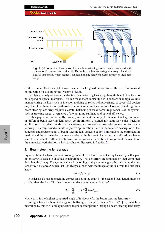
Research Article Vol. 28, No. 14 / 6 July 2020 / Optics Express 20504
Fig. 1. (a) Conceptual illustration of how a beam-steering system can be combined withconventional concentrator optics. (b) Example of a beam-steering lens array: An afocalstack of lens arrays, which redirects sunlight utilizing relative movement between these lensarrays.
et al. extended the concept to two-axis solar tracking and demonstrated the use of numericaloptimization for designing the systems [14,15].
By relying entirely on geometrical optics, beam-steering lens arrays have the benefit that they donot depend on special materials. This can make them compatible with conventional high-volumemanufacturing methods such as injection molding or roll-to-roll processing. A successful designmay, therefore, have a short path towards commercial implementation. However, the design of abeam-steering lens array requires a careful balancing of the different requirements of the system,such as tracking range, divergence of the outgoing sunlight, and optical efficiency.
In this paper, we numerically investigate the achievable performance of a large numberof different beam-steering lens array configurations designed for stationary solar trackingapplications. In order to optimize the systems, we propose and use a design method for beam-steering lens arrays based on multi-objective optimization. Section 2 contains a description of theconcepts and requirements of beam-steering lens arrays. Section 3 introduces the optimizationmethod and the optimization parameters selected in this work, including a classification schemeused to generate the different optimized configurations. In Section 4, we present the results ofthe numerical optimization, which are further discussed in Section 5.
2. Beam-steering lens arrays
Figure 2 shows the basic paraxial working principle of a basic beam-steering lens array with a pairof lens arrays stacked in an afocal configuration. The lens arrays are separated by their combinedfocal lengths f1 + f2. The system can track incoming sunlight at an angle φ by translating the lastlens array a distance ∆x such that it is always aligned with the image of the sun from the first lensarray:
∆x = f1 tan φ. (1)
In order for all rays to reach the correct lenslet in the array L2, the second focal length must besmaller than the first. This leads to an angular magnification factor M:
M =f1f2= 1 + 2
f1d
tan φmax, (2)
where φmax is the highest supported angle of incidence for the beam-steering lens array.Sunlight has an inherent divergence half-angle of approximately θ = 0.27◦ [19], which is
magnified by this angular magnification factor M after passing through a beam-steering lens array.
Pape
r4
100 Appendix A Full-text papers

Research Article Vol. 28, No. 14 / 6 July 2020 / Optics Express 20505
Fig. 2. Paraxial working principle of a simple beam-steering lens array.
The resulting divergence half-angle limits the maximum achievable concentration of a systemwith the configuration from Fig. 1(a) according to the fundamental limit to solar concentrationfor 2-axis concentration in air [2]:
Cmax =1
(sin θ)2(3)
To allow high concentration ratios, it is therefore desirable that the angular magnification of thesystem is low. This leads to a trade-off between the tracking range φmax, and divergence angle θfor this simple paraxial model of a beam-steering lens array.
It has been shown that this magnification factor can be eliminated in laser beam-steeringsystems by introducing an additional paraxial field lens to the system, where all three lens arrayshave the same focal length f [17]. This shows the importance of design choices such as thenumber and order of surfaces when designing a beam-steering lens array. We call this theconfiguration of the system, which is a topic of investigation in this work.
While utilizing the same underlying principle, there are significant differences between earliersystems for steering of laser beams [16–18] and a system designed for solar tracking:
• In solar tracking, the beam-steering system receives sunlight from varying directions andemits it in a fixed direction. The earlier proposed laser systems [16–18] work in reverse,receiving the beam from a fixed direction and emitting in a variable direction.
• In laser systems, the lens arrays usually work in the diffractive regime, and additionalphase-shifting optics are required to enable continuous beam-steering [17]. For solartracking covering larger areas, the individual lenslets can be made large enough thatthe geometrical optical approximation is appropriate, and the separate lenslets can beconsidered individually.
• The steering range used in previously proposed laser systems is 5◦ to 15◦ [18,20,21],allowing design considerations based mainly on the paraxial approximation presented inthis section. For stationary solar tracking, much larger steering angles are required, andthe simple paraxial approximation presented in this section is no longer sufficient.
• In solar tracking, the system must be able to handle broadband sunlight, requiring chromaticaberration to be taken into account.
Based on these differences, we believe that a design method based on numerical optimizationwill be best able to handle the complexities and requirements of solar tracking applications.
3. Design method
We have utilized a numerical design method based on ray-tracing and numerical multi-objectiveoptimization to design the beam-steering lens array systems. Numerical optimization is routinelyused to design optical systems, and several studies of imaging optical systems have shown howthe design space can be further explored by the use of multi-objective optimization algorithms,
Pape
r4
A Paper 4: High-performance stationary solar tracking throughmulti-objective optimization of beam-steering lens arrays
101

Research Article Vol. 28, No. 14 / 6 July 2020 / Optics Express 20506
identifying the trade-off between a set of competing system objectives [22–24]. In this section, wedescribe our design method, demonstrating how multi-objective optimization can also be utilizedto design nonimaging optical system, and we specify the conditions for the results reported laterin the paper.
3.1. Formulation of the optimization problem
We consider three main performance objectives for evaluating the performance of a completebeam-steering lens array:
• Maximizing the efficiency in redirecting sunlight.
• Minimizing the divergence of outgoing sunlight
• Minimizing the cost/complexity of the resulting systemThe design of a beam-steering lens array can be considered a multi-objective optimizationproblem. An optimized solution must provide a reasonable trade-off between these objectives.Multi-objective optimization problems can be solved by finding a set of Pareto optimal solutions:solutions where the performance in one objective cannot be improved without degradingperformance in another objective. In this way, the trade-off between objectives is quantified,allowing a designer to make an informed choice among the set of solutions [25].
Efficiency and divergence can be quantified as continuous objective functions, allowing amulti-objective optimization algorithm to map out the Pareto front between these objectives.Cost/complexity, on the other hand, is difficult to quantify and depends on several factors.Rather than quantify complexity directly, we consider cost/complexity to be influenced by theconfiguration of the beam-steering lens array – the sequence of surfaces and type of relativemovements between them. We have chosen to optimize a broad set of configurations, enablingthe comparison of different configurations with varying complexity, and allowing the selection ofa configuration with the appropriate level of complexity for a specific use case. Cost/complexitycan also be influenced by a number of other factors, including material selection, manufacturingtolerances, and optimization constraints for manufacturability - all of which are kept constant inthe present work and may be considered more thoroughly in future work.
We formulated the following optimization problem:
min f (x, θmax) = (−η (x, θmax) , θmax) (4)
such that gj (x) ≤ 0, (5)where θmax is the allowed divergence of outgoing sunlight, x is a set of free variables specifyingthe optical system (as listed in Table 2). η (x, θmax) is the average yearly optical efficiency of theoptical system subject to θmax, as described in Section 3.2. The two components of f represent thetwo objectives: Maximizing the average yearly efficiency (minimizing −η), while also minimizingthe allowed divergence (minimizing θmax). gj (x) is a set of inequality constraints as listed inTable 3, ensuring manufacturability.
3.2. Average yearly efficiency
The metric of average yearly efficiency is inspired by the work from Ito et al., who elegantlyshowed that such a metric could be used to design a tracking-integrated system [26]. We definethe average yearly optical efficiency as the fraction of yearly direct irradiation successfullyredirected in the desired direction:
η (x, θmax) =Eout (x, θmax)
Ein, (6)
where Ein is the yearly direct irradiation received by the beam-steering lens array surface, andEout (x, θmax) is the yearly irradiation successfully redirected within the permitted exit cone ±θmax.
Pape
r4
102 Appendix A Full-text papers

Research Article Vol. 28, No. 14 / 6 July 2020 / Optics Express 20507
This average efficiency can be estimated by integrating across all angles of incidence φ:
η (x, θmax) =
�⊰ π
0e (φ) × η (x, θmax, φ) dφ, (7)
where e (φ) = Ein,φ (φ)Ein
is the normalized angular distribution of irradiation received by thebeam-steering lens array in its installed location. η (x, θmax, φ) is the optical efficiency of thebeam-steering lens for an optical system x, a maximum divergence of outgoing sunlight θmax andan angle of incidence φ.
In this work, we consider the beam-steering lens arrays to have a fixed orientation, tiltedtowards the equator with an angle equal to the latitude of the installation location, as illustrated inFig. 3(a). As noted by Ito et al., this orientation gives a peak in irradiation distribution at 22◦−25◦angle of incidence, irrespective of installation location [26]. We consider the beam-steeringlens arrays optimized in this paper to be installed at a latitude of 40◦. The location of 40◦ waschosen as an example to demonstrate the principle. However, as demonstrated by Schuster [27],this angular distribution is virtually independent of installation latitude when the panel is tiltedaccording to installation latitude. We simulate the angular distribution of solar irradiation usingMeinel and Meinel’s air mass attenuation model [28] and for simplicity assume that cloud coveris not correlated to time of day or time of year. The resulting normalized irradiation distributionis shown in Fig. 3(b).
Fig. 3. (a) Assumed orientation of beam-steering lens array during optimization. (b)Simulated angular distribution of normalized yearly direct irradiation on a lens array withthe fixed orientation from a, installed at a latitude of 40°.
With this formulation, the location of the installation location, weather data, and orientationof the beam-steering lens array are all contained in the normalized angular distribution ofirradiation, e (φ), as shown in Eq. (7). The same formulation can therefore be used for optimizingbeam-steering lens arrays with the details of a planned installation, by using the appropriatedistribution e (φ). This may include real-world weather data, as well as other orientations, forinstance being oriented east or west, or being mounted on single-axis external trackers.
It is worth noting that η in Eq. (6) is defined relative to the irradiation reaching the frontsurface of the beam-steering lens array while it is mounted in its chosen orientation. The cosineprojection loss is therefore not included in the average efficiency, and will give an additionalreduction in intensity compared to a system pointed directly towards the sun. On the other hand,fixed-orientation systems can increase power conversion per land area due to reduced shadingbetween modules, as discussed by Price et al. [29]. These effects must be taken into account whencomparing tracking-integrated systems to externally tracked systems, but have been consideredto be beyond the scope of this work. Here, the aim is to compare different stationary systems thatall share the same cosine projection loss.
Pape
r4
A Paper 4: High-performance stationary solar tracking throughmulti-objective optimization of beam-steering lens arrays
103

Research Article Vol. 28, No. 14 / 6 July 2020 / Optics Express 20508
3.3. Classifying different configurations
Previously proposed beam-steering lens array designs have utilized both single-sided [13] anddouble-sided [14] lens arrays, with relative lateral [30] or curved [13] tracking motion, and withboth two [13], and three [31] lens arrays stacked together. In order to readily specify, compare,and evaluate different classes of designs, it can be useful to designate specific symbols for eachof the components in a beam-steering lens array. Specific configurations of beam-steering lensarrays can then be described using a sequence of these symbols.
In this work, we use the set of symbols shown in Table 1.The symbols from Table 1 can be used to classify both existing and new beam-steering lens
array configurations. For instance:
• The example beam-steering lens array in Fig. 1: _⤸_
• Lin et al., 2012 [13]: J⤸I
• Watson, 1993 [17] (for steering of laser beams): _↓_ and _↓_▤_
• Johnsen et al., 2018 [14]: _⤸_ and J⤸_⤸_
Table 1. Proposed symbols for classifying different beam-steering lensarray configurations.
Symbola Meaning
J Single-sided lens array with the flat side on the right.
I Single-sided lens array with the flat side on the left.
_ Double-sided lens array
JI A pair of single-sided lens arrays placed back-to-back, with index-matchedlubricating oil between them supporting relative lateral translation betweenthe lens arrays.
↓ Air-gap between lens arrays supporting a flat, lateral tracking trajectory.
⤸ Air-gap between lens arrays supporting a curved tracking trajectory.
▤ Air-gap between two surfaces, but no relative movement between thesurfaces.
aThe symbols are represented by the following Unicode [32] code-points: J=U+25C0,I=U+25B6, _=U+25C6, ↓=U+2193, ⤸=U+2938, JI=U+25C0 U+200A U+25B6,▤=U+25A4
3.4. Selecting configurations
Using the presented code for classifying beam-steering lens arrays, we have performed acomprehensive optimization of all possible combinations of the symbols in Table 1 with amaximum of 1 air-gap. This leads to a total of 52 configurations, of which 40 contains at least1 movable surface. These configurations cover the range from complex configurations suchas JI⤸JI, to simple configurations such as JI. Optimizing across this span can thereforegive good insight into the trade-off between minimizing complexity and maximizing systemperformance.
3.5. Numerical optimization
The multi-objective optimization problem in Eq. (4) was solved using a memetic version ofthe MOEA/D-DE [33] multi-objective optimization algorithm. This algorithm decomposesthe multi-objective problem into a set of scalarized sub-problems that are solved cooperatively.
Pape
r4
104 Appendix A Full-text papers

Research Article Vol. 28, No. 14 / 6 July 2020 / Optics Express 20509
We created the scalarized sub-problems by setting θmax in Eq. (4) to fixed values in the range0.5◦ ≤ θmax ≤ 5◦, which we assume to encompass the region of interest between high-accuracyand low-accuracy tracking. The MOEA/D implementation from Pymoo [34] was extendedwith the differential evolution strategy and the diversity preservation scheme proposed in theMOEA/D-DE algorithm [33]. The algorithm was then further extended to augment the globaldifferential evolution with local searches based on SciPy’s [35] implementation of the SLSQPoptimization algorithm [36], as shown in Fig. 4. The resulting memetic optimization algorithmwas run until convergence, with a limit of 10 000 iterations for each beam-steering lens arrayconfiguration.
Fig. 4. The global MOEA/D-DE optimization algorithm is combined with the SLSQP localoptimization algorithm to form a hybrid optimization algorithm. The choice between localand global search is based on the number of objective function evaluations in the local search,nfev,local compared to the total number of objective function evaluations, nfev,total. We usedk = 0.5, which means that 50% of the search effort is dedicated to the local searches.
The optimization workflow was managed using Snakemake [37]. Ray-tracing was performedusing a custom sequential three-dimensional ray-tracer, as reported in previous work [14].Hexagonal lens apertures were used for all simulations to simulate close packing in a lensarray. Optimizations were performed across the AM1.5D solar spectrum [38], and all lenseswere assumed to be made from Poly(methyl methacrylate) (PMMA). Reflection losses andchromatic aberration were taken into account, while absorption losses were not considered. Thebeam-steering lens array is a scale-invariant afocal system (as long as it is operated far away fromthe diffraction limit). Absorption losses depend on the dimensions of the system, which were notspecified in these simulations. Reflection losses were estimated according to Fresnel’s equations,taking the average of Rp and Rs and assuming that the light stays approximately unpolarizedthroughout the system. The angular distribution of sunlight was modeled using Buie’s sunshapedistribution model [39], assuming a circumsolar radiation of 5%. Average efficiency, according toEq. (7), was estimated using multi-dimensional numerical integration with a quasi-Monte Carlomethod implemented using a low-discrepancy Sobol sequence. Lens surfaces were representedas 8th order Forbes’ Qcon surfaces [40], and the full set of free variables that was optimized islisted in Table 2. The lens arrays were optimized for as-built performance by assuming uniformlydistributed positioning errors of ±0.0025 · T where T is the total thickness of the system, andassuming uniformly distributed slope errors in the surfaces of ±8 mrad, as listed in Table 3. If the
Pape
r4
A Paper 4: High-performance stationary solar tracking throughmulti-objective optimization of beam-steering lens arrays
105

Research Article Vol. 28, No. 14 / 6 July 2020 / Optics Express 20510
beam-steering lens array design is scaled to have a thickness of 20mm, this would correspond toa positioning error of 50 µm. In the ray-optical regime, errors such as curvature error, thicknesserror, surface waviness, or tracking error, all have the effect of changing the position and slopeat the point where a ray intercepts a surface [2]. All these errors are therefore combined intothe chosen error distribution for slope and position error. These errors were integrated into thequasi-Monte Carlo integration of Eq. (7) by sampling from these error distributions each time aray crosses a surface, and this approach is further discussed in Section 5.2.
Table 2. List of free variables duringoptimization of the beam-steering lens arrays
Every surface
R Radius of curvature
k Conic constant
a1, a2, a3 Aspherical Qcon coefficients
t Thickness
For the whole system
c1, c2, c3, c4 Polynomial coefficients representingtracking motion
Every tracking motion (every JI, ↓, and ⤸)
d Proportionality constant for trackingmotion
Every curved tracking motion (every ⤸)
Rt Radius of curvature of trackinggeometry
kt Conic constant for tracking geometry
at,1, at,2 Qcon polynomial representingtracking geometry
In addition to assuming a fixed distribution of positioning and slope errors, the effect of theseerrors was further investigated by optimizing the JI↓JI configuration for a set of differenterror distributions.
In each design, the lateral movements of the different lens arrays were constrained to beproportional to each other, allowing linked control, sharing the same mechanical actuator. Theaspect ratio of each lens surface was constrained to be 0.5 or less, to prevent excessively curvedlenses. Each lens array was constrained not to be thinner than half the lenslet diameter, to preventtoo thin lens arrays, and also to be no thicker than 3 times the lenslet diameter, as summarized inTable 3.
These assumptions and constraints were chosen as an example of fairly permissive constraints,to explore a broad design space and get an overview of the performance of different configurationsof beam-steering lens arrays. When planning a physical realization of such a system, theseconstraints would be modified according to the requirements of the chosen fabrication process.
Pape
r4
106 Appendix A Full-text papers

Research Article Vol. 28, No. 14 / 6 July 2020 / Optics Express 20511
Table 3. Manufacturing errors andmanufacturing constraints assumed during
optimization.
Assumed manufacturing errors (uniformdistributions, T is total system thickness)
Position error ±0.0025 · T
Slope error ±8mrad
Constraints (D is lenslet diameter)
Lens thickness (thinnest point) >0.5 · D
Lens thickness (thickest point) <3 · D
Air gap thickness (thinnest point) >0
Air gap thickness (thickest point) <2 · D
Lens aspect ratio <0.5
4. Optimization results
The result of the numerical optimization is shown in Fig. 5. Each line represents a specificbeam-steering lens array configuration, and each point along the line represents a specific designoptimized for the particular trade-off between efficiency and divergence half-angle. Given thenon-convex nature of the optimization problem, the optimization algorithm is not guaranteedto find the global optimum. The resulting Pareto front therefore only gives a lower bound onachievable efficiency for a specific configuration and divergence half-angle.
Fig. 5. Set of the best performing optimized configurations, mapping out the trade-offbetween efficiency and divergence half-angle. The value in brackets below the divergence halfangle represents the ideal geometric concentration at this divergence half-angle, accordingto Eq. (3).
Due to the number of optimized configurations, only the best-performing configurations areshown in Fig. 5. The full set is available in Fig. 11.
Pape
r4
A Paper 4: High-performance stationary solar tracking throughmulti-objective optimization of beam-steering lens arrays
107

Research Article Vol. 28, No. 14 / 6 July 2020 / Optics Express 20512
4.1. Selected results
Each point along the lines in Fig. 5 represents a separate beam-steering lens array design. Wereport on two of those designs in more detail, representing different trade-offs between efficiency,divergence, and complexity. The first result is a JI↓JI configuration optimized for a divergencehalf-angle of ±2◦, which achieves 73.4% average yearly efficiency. This represents a configurationwith high complexity, low divergence, and high efficiency. The result is highlighted with a bluecircle in the Pareto fronts in Fig. 5, and a ray-traced drawing of the system can be seen in Fig. 6.Simulated efficiency across the tracking range is shown in Fig. 8(a) and is overlaid with a yearlyirradiation distribution in Fig. 8(b).
Fig. 6. Beam-steering lens array with JI↓JI configuration optimized for 2◦ divergencehalf-angle ( in Fig. 5), drawn at 0◦ and 40◦ angles of incidence respectively. The blackarrows indicate tracking motion. The drawing shows a 2 -dimensional slice of the optimizedsystem, which consists of hexagonally packed three-dimensional lens arrays.
The second result is a JI↓I configuration optimized for ±3.5◦ divergence half-angle, whichachieves 75.4% average yearly efficiency. This is an example of a system where a lower mechanicalcomplexity is traded for a higher permitted divergence half-angle. The result is highlighted witha brown circle in the Pareto front in Fig. 5, and a ray-traced drawing of the system can be seen inFig. 7. Simulated efficiency across the tracking range is shown in Fig. 8(a), and is overlaid with ayearly irradiation distribution in Fig. 8(b).
A ray-traced 3D model of the two selected designs is shown in Fig. 9. Zemax OpticStudiomodels are available as we show in Code 1 (Ref. [41]), and a comparison between the ZemaxOpticStudio models and the internal ray-tracer models are included in Appendix C.
4.2. Influence of position and slope errors
To investigate the influence of position and slope errors on the optimization results, the JI↓JIdesign was optimized for a set of error distributions with magnitudes different from the onesdescribed in Table 3. The Pareto fronts for the different error distributions is shown in Fig. 10(a),while a tolerance analysis of selected designs is shown in Fig. 10(b). In addition, all configurationswere also optimized for nominal performance assuming no errors, and the resulting Pareto frontsare included in Fig. 12 in Appendix B.
Pape
r4
108 Appendix A Full-text papers

Research Article Vol. 28, No. 14 / 6 July 2020 / Optics Express 20513
Fig. 7. Simplified beam-steering lens array with JI↓I configuration optimized for 3.5◦divergence half-angle ( in Fig. 5), drawn at 0◦ and 40◦ angles of incidence respectively.The black arrows indicate tracking motion. The drawing shows a 2-dimensional slice of theoptimized system, which consists of hexagonally packed three-dimensional lens arrays.
Fig. 8. (a) The two selected beam-steering lens arrays have >80% efficiency for ±40◦angleof incidence, and a gradual drop-off in efficiency at larger angles of incidence. The dashedcurves show nominal performance, while the continuous curves show expected performancewith the chosen set of error distributions. (b) When the systems are placed in a fixedorientation as described in Section 3.2, this efficiency distribution corresponds to averageyearly efficiency of 73.5% for the high concentration design and 75.6% for the simplifieddesign, respectively.
Pape
r4
A Paper 4: High-performance stationary solar tracking throughmulti-objective optimization of beam-steering lens arrays
109

Research Article Vol. 28, No. 14 / 6 July 2020 / Optics Express 20514
Fig. 9. Ray-traced 3D-model of the two selected beam-steering lens arrays, both shown at a40◦ angle of incidence. (a) JI↓I configuration optimized for a permitted divergence of3.5◦, (b) JI↓JI configuration optimized for a permitted divergence of 2.0◦.
Fig. 10. (a) Optimized Pareto fronts for the JI↓JI configuration, assuming differentscaled versions of the error distributions in Table 3. 100% corresponds to the valuesreported in the table. The achievable performance is strongly influenced by the scale ofmanufacturing errors, as can be seen by the large changes to the Pareto fronts. (b) Theselected designs from a are simulated at different error distributions to see how sensitive theyare to errors. The system optimized for nominal performance has the highest performance atzero manufacturing errors, but is also the most sensitive to such errors.
Pape
r4
110 Appendix A Full-text papers

Research Article Vol. 28, No. 14 / 6 July 2020 / Optics Express 20515
5. Discussion
Stationary solar tracking requires beam-steering lens arrays with a wide dual-axis tracking range,making it difficult to rely on paraxial models and experience from conventional optical design tochoose the ideal configuration. The use of numerical multi-objective optimization has enabledscreening of many different configurations, to identify designs that are promising for futureimplementations of this concept.
The optimization results show that fairly complex optical systems are required to achieve highefficiency and low divergence for stationary solar tracking. The complex JI⤸JI and JI↓JIconfigurations outperform all the other configurations in Fig. 5 across the entire Pareto front.
At higher permitted divergence half-angles, some additional systems achieve relatively highefficiency, more specifically the class of systems starting with a JI-pair of single-sided lensarrays.
Simpler configurations with only 1 moving surface, such as _⤸_ or JI do not have therequired degrees of freedom to enable high-efficiency stationary solar tracking. As seen in Fig. 5,the _⤸_ configuration only achieves 67% average yearly efficiency when divergence half-angleis permitted to be as high as ±5.00◦.
The selected results presented in Section 4.1 represent two different prioritizations of thedifferent objectives, and they represent designs that we believe might be of interest for solarenergy applications. The high-complexity JI↓JI design in Fig. 6 redirects sunlight into anarrow cone of ±2◦ divergence. It may therefore be relevant for high concentration applications,such as concentrator photovoltaics (CPV) or high-temperature concentrated solar power (CSP)applications. Figure 5 shows how even higher performance can be achieved with a JI⤸JIconfiguration, but the additional complexity in implementing a curved tracking trajectory mightnot be worth the relatively minor improvements to performance.
The selected JI↓I design offers a simpler mechanical implementation with 3 lens arraysinstead of 4. This reduced complexity comes at the cost of increased permitted divergencehalf-angle. The permitted divergence angle of ±3.5◦ represents a geometric concentration limitof 268x according to Eq. (3), which is still 26% higher than the 1
sin(0.27◦) ≈ 212 concentrationlimit of conventional linear trough concentrators with single-axis tracking [2]. We thereforebelieve that this design might be of interest for low- to medium temperature CSP applications.
The beam-steering lens arrays demonstrated here emit collimated and redirected sunlight. Tobe used in CSP or CPV applications, these devices must be combined with a solar concentrator,for instance in the configuration illustrated in Fig. 1(a). An investigation into the best way to addsuch a concentrator, as well as a comparison of the resulting performance compared to othertracking-integrated solar concentrators, will be of interest for future development of this concept.
5.1. Optimizing for as-built performance
As described in Section 3.5, the systems were optimized for as-built performance by estimatingthe expected efficiency under the influence of manufacturing errors. Optimizing the systems foras-built performance is important because a system optimized for nominal performance can bevery sensitive to manufacturing errors, while a system with slightly lower nominal performancemay exhibit significantly lower sensitivity to surface errors [42]. We consider optimizationfor as-built performance to be especially important in the type of screening performed in thiswork, in order to not unrealistically favor highly complex configurations that may turn out torequire very strict manufacturing tolerances. This effect is demonstrated in the tolerance analysisin Fig. 10(b): The system optimized for nominal performance is more sensitive to errors thansystems optimized for as-built performance.
The optimization results are strongly affected by the chosen error distributions, as seen inFig. 10(a), where the same configuration has been optimized for different error distributions.The distributions in this work were chosen as an example to demonstrate how the systems can
Pape
r4
A Paper 4: High-performance stationary solar tracking throughmulti-objective optimization of beam-steering lens arrays
111

Research Article Vol. 28, No. 14 / 6 July 2020 / Optics Express 20516
be optimized while taking manufacturing errors into account, and as a common ground forcomparing the different beam-steering lens array configurations. When planning a real-worldimplementation of a beam-steering lens array, these error distributions should be updated tomore accurately match selected manufacturing tolerances of the chosen lens molding processand system assembly.
Due to the strong influence of the error distributions, it can be difficult to compare the resultsin Fig. 5 with other related work optimized for different tolerances, or for nominal performance.For this reason, we have also included Pareto fronts optimized for nominal performance, availablein Fig. 12 in Appendix B. The nominal results in Fig. 12 can be useful for comparing the beam-steering lens array configurations in this work against other alternatives optimized for nominalperformance. However, we expect the nominal designs to be too sensitive to manufacturingerrors to be used as a basis a physical beam-steering lens array, and therefore keep them outsidethe main body of the paper.
5.2. Implementation
There is no universally accepted way to optimize an optical system for reduced sensitivity tomanufacturing errors, and different optical design software packages have implemented differentheuristics to try to achieve this goal [42]. The task is especially challenging in conventionaloptical design, where the design of each individual system is of interest. In these designs,tolerance analysis is typically performed by sampling each surface error from the manufacturingtolerances, before applying an error compensation such as a refocus and simulating the resultingperformance of the whole system. In the case of a beam-steering lens array, on the other hand,the object of interest is the combined average performance of the full set of lenses in the lensarrays, each subject to their own set of errors. We have therefore chosen to directly integratethe error distributions into the objective function by including them in the quasi-Monte Carlointegration of Eq. (7). In this way, each ray traced through the system is subject to a unique set ofmanufacturing errors sampled from the error distribution. This approach enables fast calculationof the average performance of a system subject to the selected error distributions, allowing theestimate to be directly used during optimization.
Unlike conventional tolerance analysis, our approach does not enable the use of compensators.The estimate might, therefore, be too pessimistic when estimating the influence of lateralpositioning errors, which can likely be partially compensated for by the closed-loop trackingsystem in a physical realization of a beam-steering lens array. When planning a real-worldimplementation of a beam-steering lens array, the resulting design should therefore also besubjected to conventional tolerance analysis to more accurately validate the predicted as-builtperformance.
5.3. Multi-objective optimization
The use of a multi-objective optimization algorithm has enabled a comprehensive screening alarge number of configurations of beam-steering lens arrays for stationary solar tracking, withouthaving to make an upfront decision for the trade-off between permitted divergence angle andefficiency.
The permitted divergence angle is related to the achievable concentration ratio through Eq. (3).The trade-off curves in Fig. 5 are therefore a representation of the efficiency-versus-concentrationcurves known from Nonimaging Optics [2], and the objective function in Eq. (4) can be considereda special case of the overall problem in Nonimaging Optics of simultaneously optimizing bothefficiency and concentration. The use of multi-objective optimization algorithms may, therefore,be of general interest to several problems in the field of Nonimaging Optics, and may constitute atopic of further future investigation beyond the topic of beam-steering lens array design.
Pape
r4
112 Appendix A Full-text papers

Research Article Vol. 28, No. 14 / 6 July 2020 / Optics Express 20517
6. Conclusions
We have performed a thorough screening of beam-steering lens array configurations in order toidentify the most promising configurations for stationary solar tracking applications. This wasenabled by using a set of symbols to specify and generate each configuration, and optimizing eachconfiguration using multi-objective numerical optimization. The multi-objective optimizationapproach has enabled the optimization of beam-steering lens arrays without having to make anup-front decision for the trade-off between efficiency and divergence. The approach also enablesthe handling of manufacturing constraints and expected manufacturing errors, and may be ofinterest for other design problems in the field of nonimaging optics.
From this screening, we have identified beam-steering lens array designs capable of highefficiency full-day stationary solar tracking, and we specifically picked out two designs thatmight be candidates for solar energy applications. The first design has relatively high mechanicalcomplexity with 4 optical surfaces, and can be suitable for high-concentration applications,achieving 73.4% average yearly efficiency in redirecting sunlight into a <2◦ divergence half-angle. The second system has lower complexity, with 3 optical surfaces, and may be suitablefor low-concentration applications. It achieves 75.4% average yearly efficiency in redirectingsunlight into a <3.5◦ divergence half-angle. These reported configurations may contribute tothe development of low-cost tracking-integrated solar energy, and further the development oftracking-integrated solar concentrators.
Pape
r4
A Paper 4: High-performance stationary solar tracking throughmulti-objective optimization of beam-steering lens arrays
113

Research Article Vol. 28, No. 14 / 6 July 2020 / Optics Express 20518
Appendix A Full optimization results
Fig. 11. Full set of trade-off curves for different configurations of beam-steering lens arraysoptimized as described in Section 3.5.
Pape
r4
114 Appendix A Full-text papers
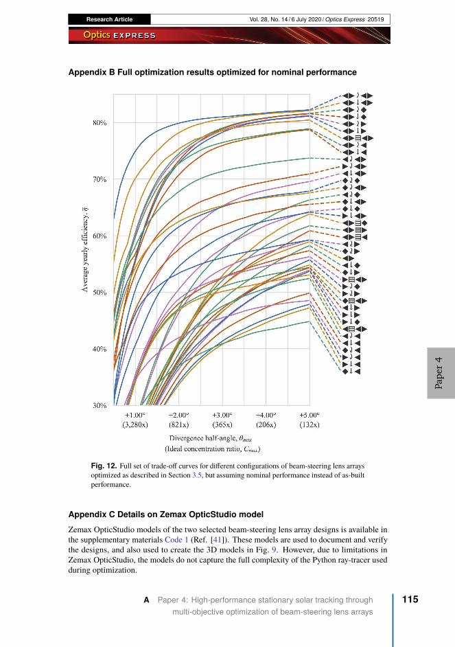
Research Article Vol. 28, No. 14 / 6 July 2020 / Optics Express 20519
Appendix B Full optimization results optimized for nominal performance
Fig. 12. Full set of trade-off curves for different configurations of beam-steering lens arraysoptimized as described in Section 3.5, but assuming nominal performance instead of as-builtperformance.
Appendix C Details on Zemax OpticStudio model
Zemax OpticStudio models of the two selected beam-steering lens array designs is available inthe supplementary materials Code 1 (Ref. [41]). These models are used to document and verifythe designs, and also used to create the 3D models in Fig. 9. However, due to limitations inZemax OpticStudio, the models do not capture the full complexity of the Python ray-tracer usedduring optimization.
Pape
r4
A Paper 4: High-performance stationary solar tracking throughmulti-objective optimization of beam-steering lens arrays
115

Research Article Vol. 28, No. 14 / 6 July 2020 / Optics Express 20520
The Zemax OpticStudio model includes a Merit Function used to evaluate optical efficiencyat the discrete set of angle of incidence. This merit function is used to verify the performanceof the beam-steering lens arrays, as shown in Fig. 13. However, the merit function does notimplement the design method described in Section 3, and is not suitable for optimization usingthe built-in optimization algorithms in Zemax OpticStudio, which do not support multi-objectiveoptimization.
Fig. 13. Comparing internal Python model and Zemax OpticStdio model of the selectedbeam-steering lens array designs. The Zemax OpticStudio model assumes nominal per-formance and constant azimuth angle, and the simulated efficiencies agree well with theinternal Python model when these assumptions are replicated.
The efficiency estimate from Zemax OpticStudio contains the following set of simplificationscompared to the Python model:
• Tracking motion is represented at a set of discrete angles of incidence using the multi-configuration functionality in Zemax OpticStudio. During optimization, tracking motionis represented as a continuous function of angle of incidence.
• The builtin PMMA material model in Zemax OpticStudio is only defined between 365nmand 1060nm, and the AM1.5D solar spectrum is therefore clipped to this range. Duringoptimization, the whole AM1.5D spectrum is used.
• For simplicity, the Zemax OpticStudio model only demonstrates solar tracking across 1axis – in other words, with a constant azimuth angle. Since lenslets are packed hexagonallyand thus not completely rotationally symmetric, tracking performance is not fully uniformacross different azimuth angles. During optimization, the azimuth angle is included as anintegration dimension in the multi-dimensional quasi-Monte Carlo integration of Eq. (7).
• The Zemax OpticStudio model estimates nominal system performance, not as-builtperformance, as discussed in Section 5.1.
• During optimization, the lenslet surfaces are represented using 8th order Forbes’ Qcon
surfaces [40]. When creating the Zemax OpticStudio models, this representation isconverted to an even polynomial representation, in order to be represented as ZemaxOpticStudio’s “Hexagonal Lenslet Array” object type.
Pape
r4
116 Appendix A Full-text papers

Research Article Vol. 28, No. 14 / 6 July 2020 / Optics Express 20521
• The Zemax OpticStudio system is modeled as a lens array with 9 by 9 lenslets, and thesource is modeled as a rectangular source aimed towards this array. There might thereforebe small edge-effects, where some of the lenslets are only partially illuminated. Duringoptimization, an infinite array of lenslets is assumed.
Acknowledgments
Portions of this work were presented at the SPIE Optical Engineering + Applications conferencein 2019, paper number 111200B [15], and at the SPIE Optical Engineering + Applicationsconference in 2018, paper number 1075805 [14].
Disclosures
The authors declare no conflicts of interest.
References1. W. T. Xie, Y. J. Dai, R. Z. Wang, and K. Sumathy, “Concentrated solar energy applications using Fresnel lenses: A
review,” Renewable Sustainable Energy Rev. 15(6), 2588–2606 (2011).2. R. Winston, J. C. Minano, P. G. Benitez, W. N. Shatz John, C. Bortz, and J. C. Bortz, Nonimaging Optics (Elsevier
Science, 2005).3. H. Apostoleris, M. Stefancich, and M. Chiesa, “Tracking-integrated systems for concentrating photovoltaics,” Nat.
Energy 1(4), 16018 (2016).4. F. Duerr, Y. Meuret, and H. Thienpont, “Tracking integration in concentrating photovoltaics using laterally moving
optics,” Opt. Express 19(S3), A207–A218 (2011).5. F. Duerr, Y. Meuret, and H. Thienpont, “Tailored free-form optics with movement to integrate tracking in concentrating
photovoltaics,” Opt. Express 21(S3), A401–A411 (2013).6. A. J. Grede, J. S. Price, and N. C. Giebink, “Fundamental and practical limits of planar tracking solar concentrators,”
Opt. Express 24(26), A1635–A1646 (2016).7. P. Kotsidas, V. Modi, and J. M. Gordon, “Nominally stationary high-concentration solar optics by gradient-index
lenses,” Opt. Express 19(3), 2325–2334 (2011).8. V. Narasimhan, D. Jiang, and S.-Y. Park, “Design and optical analyses of an arrayed microfluidic tunable prism panel
for enhancing solar energy collection,” Appl. Energy 162, 450–459 (2016).9. L. D. DiDomenico, “Towards doubling solar harvests using wide-angle, broad-band microfluidic beam steering
arrays,” Opt. Express 23(24), A1398–A1417 (2015).10. N. León, C. Ramírez, and H. García, “Rotating Prism Array for Solar Tracking,” Energy Procedia 57, 265–274
(2014).11. S. Valyukh, I. Valyukh, and V. Chigrinov, “Liquid-Crystal Based Light Steering Optical Elements,” Photonics Lett.
Pol. 3(2), 88–90 (2011).12. R. Campbell and M. Machado, “LOW cost CPV = Embedded CPV with internal tracker,” in 2010 35th IEEE
Photovoltaic Specialists Conference, (IEEE, 2010), pp. 003003–003007.13. W. Lin, P. Benitez, and J. C. Miñano, “Beam-steering array optics designs with the SMS method,” Proc. SPIE 8485,
848505 (2012).14. H. J. D. Johnsen, J. Torgersen, and A. Aksnes, “Solar tracking using beam-steering lens arrays,” Proc. SPIE 10758, 4
(2018).15. H. J. D. Johnsen, A. Aksnes, and J. Torgersen, “Pushing the limits of beam-steering lens arrays,” Proc. SPIE 11120,
10 (2019).16. K. M. Flood, B. Cassarly, C. Sigg, and J. Finlan, “Continuous wide angle beam steering using translation of binary
microlens arrays and a liquid crystal phased array,” Proc. SPIE 1211, 296–304 (1990).17. E. A. Watson, “Analysis of beam steering with decentered microlens arrays,” Proc. SPIE 32(11), 2665–2670 (1993).18. A. Akatay, C. Ataman, and H. Urey, “High-resolution beam steering using microlens arrays,” Opt. Lett. 31(19),
2861–2863 (2006).19. S. A. Kalogirou, Solar Energy Engineering: Processes and Systems (Academic, 2013).20. J. Bourderionnet, M. Rungenhagen, D. Dolfi, and H. D. Tholl, “Continuous laser beam steering with micro-optical
arrays: Experimental results,” Proc. SPIE 7113, 71130Z (2008).21. J. Xiang, N. Wu, J. Zhang, and L. Wu, “Design of driving and control system based on Voice Coil Actuation for
linear motion of micro-lens array,” Proc. SPIE 7133, 713330 (2009).22. I. Ono, S. Kobayashi, and K. Yoshida, “Global and multi-objective optimization for lens design by real-coded genetic
algorithms,” Proc. SPIE 3482, 110–121 (1998).23. Bráulio Fonseca Carneiro de Albuquerque, F. L. de Sousa and A. S. Montes, “Fonseca Carneiro de Albuquerque
Multi-objective approach for the automatic design of optical systems,” Opt. Express 24(6), 6619–6643 (2016).
Pape
r4
A Paper 4: High-performance stationary solar tracking throughmulti-objective optimization of beam-steering lens arrays
117

Research Article Vol. 28, No. 14 / 6 July 2020 / Optics Express 20522
24. C. C. Olson, “Automated design of optical architectures using novel encoding methods and a multi-objectiveoptimization framework,” Proc. SPIE 11105, 11 (2019).
25. P. M. Pardalos, A. Žilinskas, and J. Žilinskas, Non-Convex Multi-Objective Optimization, Springer Optimization andIts Applications (Springer International Publishing, 2017).
26. A. Ito, D. Sato, and N. Yamada, “Optical design and demonstration of microtracking CPV module with bi-convexaspheric lens array,” Opt. Express 26(18), A879–A891 (2018).
27. C. S. Schuster, “The quest for the optimum angular-tilt of terrestrial solar panels or their angle-resolved annualinsolation,” Renewable Energy 152, 1186–1191 (2020).
28. A. B. Meinel and M. P. Meinel, Applied Solar Energy: An Introduction (Addison-Wesley, 1976).29. J. S. Price, X. Sheng, B. M. Meulblok, J. A. Rogers, and N. C. Giebink, “Wide-angle planar microtracking for
quasi-static microcell concentrating photovoltaics,” Nat. Commun. 6(1), 6223 (2015).30. E. Watson, D. Miller, and K. Barnard, “Analysis of fill factor improvement using microlens arrays,” Proc. SPIE 3276,
123–134 (1998).31. J. Duparré, D. Radtke, and P. Dannberg, “Implementation of field lens arrays in beam-deflecting microlens array
telescopes,” Appl. Opt. 43(25), 4854–4861 (2004).32. Unicode Consortium, The Unicode Standard, Version 12.0 (2019).33. H. Li and Q. Zhang, “Multiobjective Optimization Problems With Complicated Pareto Sets, MOEA/D and NSGA-II,”
IEEE Trans. Evol. Computat. 13(2), 284–302 (2009).34. J. Blank and K. Deb, “Pymoo: Multi-Objective Optimization in Python,” IEEE Access 8, 89497–89509 (2020).35. P. Virtanen, R. Gommers, T. E. Oliphant, M. Haberland, T. Reddy, D. Cournapeau, E. Burovski, P. Peterson, W.
Weckesser, J. Bright, S. J. van der Walt, M. Brett, J. Wilson, K. J. Millman, N. Mayorov, A. R. J. Nelson, E. Jones, R.Kern, E. Larson, C. J. Carey, İ. Polat, Y. Feng, E. W. Moore, J. VanderPlas, D. Laxalde, J. Perktold, R. Cimrman, I.Henriksen, E. A. Quintero, C. R. Harris, A. M. Archibald, A. H. Ribeiro, F. Pedregosa, P. van Mulbregt, and S. .Contributors, “SciPy 1.0: Fundamental algorithms for scientific computing in Python,” Nat. Methods 17(3), 261–272(2020).
36. D. Kraft, “A software package for sequential quadratic programming,” Tech. Rep. DFVLR-FB 88-28, DLR GermanAerospace Center – Institute for Flight Mechanics (Koln Germany, 1988).
37. J. Köster and S. Rahmann, “Snakemake—a scalable bioinformatics workflow engine,” Bioinformatics 28(19),2520–2522 (2012).
38. Renewable Resource Data Center, Solar Spectral Irradiance: Air Mass 1.5, https://rredc.nrel.gov/solar/spectra/am1.5/.39. D. Buie, A. G. Monger, and C. J. Dey, “Sunshape distributions for terrestrial solar simulations,” Sol. Energy 74(2),
113–122 (2003).40. G. W. Forbes, “Shape specification for axially symmetric optical surfaces,” Opt. Express 15(8), 5218–5226 (2007).41. H. J. D. Johnsen, A. Aksnes, and J. Torgersen, “Zemax OpticStudio Models of Beam-Steering Lens Arrays, figshare,”
(2020). https://doi.org/10.6084/m9.figshare.1250578442. K. E. Moore, “Optimization for as-built performance,” Proc. SPIE 10925, 1 (2019).
Pape
r4
118 Appendix A Full-text papers

Paper 5: Beyond the 2D limit:Étendue-squeezing line-focus solarconcentrators
Pape
r5

Pape
r5
120 Appendix A Full-text papers

Letter Optics Letters 1
Beyond the 2D limit: Étendue-squeezing line-focussolar concentratorsHÅKON J. D. JOHNSEN1,*, ASTRID AKSNES2, AND JAN TORGERSEN1
1Norwegian University of Science and Technology, Department of Mechanical and Industrial Engineering, Richard Birkelands Vei 2b, Trondheim, Norway2Norwegian University of Science and Technology, Department of Electronic Systems, O.S. Bragstads plass 2b, Trondheim, Norway*Corresponding author: [email protected]
Compiled November 15, 2020
Line-focus solar concentrators are commonly designedby extruding a two-dimensional concentrator in thethird dimension. For concentration in air, these concen-trators are, by the nature of their design, limited by thetwo-dimensional solar concentration limit of 212x. Thislimit is orders of magnitude lower than the 45 000x con-centration limit for three-dimensional solar concentra-tors. Through the use of étendue-squeezing, we concep-tually show that it is possible to design line-focus solarconcentrators beyond this 2D limit. This allows a con-centrator to benefit from a line-focus suitable for heat-extraction through a tubular receiver, while reachingconcentration ratios and acceptance angles previouslyunseen for line-focus concentrators. We show two de-sign examples, achieving a simulated 75x concentrationand 218x concentration ratio respectively, with a ±1◦ ac-ceptance angle. For comparison, the 2D concentrationlimit is 57x at this acceptance angle. Étendue-squeezingline-focus solar concentrators, combined with recentdevelopments in tracking-integration, may enable thedevelopment of a new class concentrated solar power(CSP) system. © 2020 Optical Society of America
http://dx.doi.org/10.1364/ao.XX.XXXXXX
Solar concentrators are essential for efficient utilization of solarthermal energy, and have a fundamental concentration limit inair of
Cmax =1
(sin θmax)2 (1)
where θmax is the acceptance angle of the concentrator, whichmust at least be wide enough for the θ ≈ 0.27◦ divergencehalf-angle of sunlight. This leads to a solar concentration limitin air of approximately 45 000x[1]. To approach the limit, theconcentrator must concentrate sunlight in three dimensions,which traditionally means concentrating to a point-like focus.The high fundamental concentration limit enables point-focussolar concentrators to be designed with large acceptance anglesand non-ideal optics, and still achieve sufficient concentrationfor many applications. In the remainder of this paper we willbe considering the condition θmax = 1◦, where the increased
acceptance angle represents an increased tolerance to tracking-and surface errors. At this increased acceptance angle, the two-dimensional concentration limit is 3 283x.
Solar concentrators can also be built to concentrate sunlightto a line-focus. Such a line-focus is suitable for heat extractionthrough tubular receivers, and can also be designed to benefitfrom a simplified one-axis tracking motion. Line-focus concen-trators are commonly designed by extruding two-dimensionalconcentrator geometries, which limits the concentration in air tothe 2D concentration limit[1]:
Cmax,2D =1
sin θmax. (2)
For a solar divergence half-angle of θ = 0.27◦, the limit is ap-proximately 212x, and with the 1◦ acceptance angle consideredin this paper it is reduced to 57x. The 2D and 3D limits in Eqs.1-2 are plotted against acceptance angle in Figure 1.
0.27°0.5° 1° 2° 4° 8° 15° 30° 60°Acceptance angle, max
1x
10x
100x
1000x
10 000x
Con
cent
ratio
n lim
it, C
max 3D limit
2D limitDesign oneDesign two
Fig. 1. Concentration limits versus acceptance angle, as givenby Eqs. 1-2, shown on a log-log scale. The line-focus concentra-tors demonstrated in this work, represented by the symbolsand , have concentration ratios beyond the 2D concentrationlimit.
It has previously been shown that the concentration ratio oflinear primary concentrators can be boosted beyond the 2D con-centration limit by introducing secondary concentrators close tothe line-focus, reaching concentration ratios of 300x with one-axis polar tracking[2], or >1000x with two-axis tracking[3, 4].
Pape
r5
A Paper 5: Beyond the 2D limit: Étendue-squeezing line-focussolar concentrators
121

Letter Optics Letters 2
However, these secondary concentrators achieve their increasedconcentration ratio by breaking the line-focus into a set of smallpoint- or line-foci, missing the benefit of a true line-focus fortubular receivers (as further illustrated in Fig. S3 of the Supple-mental Document). It has also been shown that the 2D limit canbe surpassed using nominally linear concentrators where thetranslational symmetry is broken by ridges in the concentrator,but these have focused on relatively large acceptance anglessuitable for stationary solar concentration[5–7].
We show that the common approach of extruding a two-dimensional concentrator is not the only way to design a line-focus concentrator, and demonstrate a method to directly con-struct a 3D concentrator that concentrates to a line-focus. Thus, itis possible to benefit from the high concentration of 3D concentra-tors while maintaining the practical benefits for heat-extractionthrough tubular receivers placed along a line-focus. The useof such a high-concentration line-focus concentrator would re-quire two-axis tracking, but this does not necessarily mean that itneeds to be mounted on a two-axis external solar tracker. Instead,tracking across the secondary axis may be implemented withoutphysical rotation of the concentrator, similar to what has previ-ously been demonstrated with tracking-integrated solar concen-trators for concentrator photovoltaics (CPV) applications[8].
An afocal pair of lens surfaces can be used to compress anoptical beam in one axis, while expanding it in the other axis,as illustrated in Figure 2a. If the ratio of compression and ex-pansion is 1:N where N is an integer, the lens pairs can be tes-sellated in such a way that they fill the front and back surfacesof a lens array, as shown in Figure 2b [9]. This is known asan étendue-squeezing lens array, as introduced in José Blen’s2007 thesis[10], and is an example of the more general concept ofétendue-squeezing[11]. The étendue-squeezing lens array tradesangular extent along one axis against angular extent along theother axis by a factor N[9]. It has been demonstrated for applica-tions such as changing the aspect ratio of the collimated beamfrom an LED source[9].
Tesselated array ofétendue-squeezing elements
Incoming light
Outgoing light,compressed in x-directionand expanded in y-direction
xy
z
(a)
(b)
Fig. 2. (a) Principle of étendue-squeezing using an afocallens pair. (b) The lens-pairs can be tessellated into a completeétendue-squeezing lens array.
By adjusting the lens geometry, the étendue-squeezing lensarray can be used to create a solar concentrator with a line-focus:Instead of emitting the collimated beam, as shown in Fig. 2, eachlens-pair can be optimized to redirect the sunlight towards ashared focal line. The principle, as well as a complete such solar
concentrator, are shown in Figure 3. Such a concentrator thusbecomes a combination of a linear Fresnel lens — redirecting thesunlight towards a shared focal line, and an étendue-squeezinglens array — reducing angular extent in the y-direction to permithigher concentration ratios. As shown in the design examplesbelow, this principle enables the concentrator to utilize two-axistracking and bypass the 2D concentration limit.
xy
zx
y
z
Fig. 3. A solar concentrator utilizing étendue-squeezing, con-sisting of an array of tessellated étendue-squeezing lens pairs.Each lens-pair squeezes the beam in the x-direction and ex-pands it in the y-direction, while redirecting the sunlighttowards the common focal line. The cutout shows one suchlens-pair highlighted in green, and demonstrates how the lens-pairs are tessellated into a complete double-sided lens array.
To demonstrate the principle, we used numerical optimiza-tion to create two line-focus solar concentrators: One concen-trator consists of only a double-sided lens array, and one con-centrator uses an additional secondary reflector. Both designswere constructed with an étendue squeezing factor of N = 7 (theratio of the short to the long side of the individual rectangularfacets is 1:7). The factor 7 was chosen as an example, with theaim of being high enough to allow for significant concentrationboost, while low enough to allow for practical implementation.Each individual lens-pair was numerically optimized accordingto its position in the concentrator, using a custom Python ray-tracer. Optimization was performed using a memetic optimiza-tion algorithm combining the SLSQP and Differential Evolutionalgorithms from the Scipy library[12]. The optimization wasperformed in two stages: In the first stage, a small subset ofthe lens pairs were optimized to identify a realistic geometricconcentration ratio where efficiency on the order of 80% could beexpected. In the second stage, all lens pairs were independentlyoptimized for maximum efficiency at the geometric concentra-tion ratio chosen from the first stage. The freeform front- andback- surfaces were represented as 6th order Legendre polyno-mials, chosen for being orthogonal in sag on the rectangular lensaperture[13]. Due to the problem’s symmetry, only Legendreterms symmetric in the x-direction were allowed to be non-zeroduring optimization. After optimization, the lens pairs were tes-sellated and combined into a Zemax OpticStudio model to verifyand evaluate the complete system. These Zemax OpticStudiomodels are available in the supplementary material as we showin Code 1 (Ref. [14]). The lens arrays are assumed to be madefrom PMMA, and illuminated using the AM1.5D spectrum and atop-hat ±1◦ angular distribution. This angular distribution was
Pape
r5
122 Appendix A Full-text papers

Letter Optics Letters 3
chosen as an example, to demonstrate the possibility of design-ing for high tolerance to tracking errors. Reflection losses andchromatic aberration are taken into account. For simplicity, vol-ume absorption and surface scattering losses were not includedin the simulation of these design examples. For simplicity, theabsorbing surface is assumed to be planar. The optimization ofconcentrator performance with tubular receivers is left for futurework, and may involve the adaptation of techniques previouslydeveloped for high-concentration 2D concentrators for tubularreceivers[15].
y x
z
Design 2
Design 1
Double-sided étendue-squeezing lens array
Secondary aluminum reflector
Fig. 4. Ray-traced drawing of the two design examples. Only asubset of the lens-pairs are drawn and traced, to reduce clutterin the drawing. In reality, the lens-pairs are tessellated to fillthe entire front and back surfaces of the lens array, as shown inFig. 3.
The first design example is a double-sided lens array, for op-eration similar to a linear Fresnel lens. A ray-traced 3D modelof the optimized concentrator is shown in Fig. 3, and a 2Ddrawing is shown in Fig. 4. The concentrator is optimized for a95x geometric concentration ratio under ±1◦ illumination, andachieves 79.1% efficiency at these conditions. This leads to aneffective optical concentration of Ce f f = 0.791 · 95 ≈ 75.1. Theresulting concentrator has an optimized numerical aperture ofNA = 0.32 ( f /1.47). The intensity across the focal line of the ofthe concentrator is shown in Fig. 5, and the angular acceptanceis shown in Fig. 6. Further details about the compression of an-gular extent performed by this concentrator is shown in Fig. S1of the Supplemental Document. This concentrator demonstratesthat it is possible to surpass the 2D concentration limit, but theconcentration ratio of this example design is still only about 31%higher than the 2D limit. The low numerical aperture of theresulting concentrator indicates that the concentration can beincreased by a high numerical aperture secondary concentrator,leading us to the next design example.
The second design example combines the étendue-squeezinglens array with a reflective secondary concentrator assumed tobe made from aluminum. The geometry of this reflective sec-ondary is designed so that the resulting concentrator is approxi-mately aplanatic, a condition that has previously been shown togenerate concentrators with performance very close to the funda-mental concentration limit[16, 17]. The numerical aperture of theresulting concentrator was NA = 0.89, chosen to be relativelyclose to 1 for high concentration, while having a more practicalgeometry than a concentrator fully reaching NA = 1. Optimized
0.02 0.01 0.00 0.01 0.02Normalized y-position
(relative to concentrator half-width)
0
50
100
150
200
250
Nor
mal
ized
irra
dian
ce(r
elat
ive
to 1
x so
lar i
rrad
ianc
e)
Design 1Cg=95=79.1%
Design 2Cg=280=78.0%
Ideal LinearCg=57.3=100%
Fig. 5. Intensity profile across the focal line for the two concen-trators, under 1 sun AM1.5D illumination with a ±1◦ top-hatangular distribution. The solid lines represent the intensitywithin the selected geometric concentration ratios. The non-uniform intensity profile of the ideal linear concentrator iscaused by the circular ±1◦ angular distribution of the illumi-nation, as further discussed in the Supplemental Document.
for a geometric concentration ratio of 280x, this concentratorachieves 78.0% efficiency under ±1◦illumination. This leads toan effective optical concentration of Ce f f = 0.780 · 280 ≈ 218.The intensity across the focal line of the concentrator shown inFig. 5 and the angular acceptance of the concentrator is shownin Fig. 6.
0.025 0.000 0.025L
0.025
0.000
0.025
M
Design 1
0.025 0.000 0.025L
Design 2
0% 20% 40% 60% 80% 100%
Fig. 6. Optical efficiency of the concentrators as a function ofincidence angle, shown as contour plots in direction cosinespace. L and M are direction cosines along the x- and y-axis,respectively. The concentrators are optimized for maximumefficiency under a ±1◦ top-hat angular distribution, which isillustrated by the red circles.
The presented design examples have modeled efficienciesof 79.1% and 78.0%, respectively. The losses arise from reflec-tion losses in the lens array, geometric losses from shading ofneighboring elements in the lens array, absorption losses in thereflector, and finally, a non-unity intercept factor. Volume ab-sorption losses, surface scattering losses, and losses due to man-ufacturing tolerances were not included in these simulations.The relative magnitude of each loss was measured by selectivelydisabling loss mechanisms while simulating the system, and aresummarized in Table 1.
Pape
r5
A Paper 5: Beyond the 2D limit: Étendue-squeezing line-focussolar concentrators
123

Letter Optics Letters 4
Table 1. Relative magnitude of different losses in the designs
Design 1 Design 2
Lens array reflection loss 7.8% 7.6%
Lens array geometric loss 3.2% 2.6%
Reflector absorption loss - 5.4%
Intercept loss 11.4% 8.3%
Complete efficiency 79.1% 78.0%
A consequence of the decreased angular extent along the y-axis in these concentrators is an increased angular extent alongthe x-axis. This angular extent leads to a gradual reductionin intensity at the ends of the line-focus, as illustrated in Fig.7. The effect can be eliminated by using edge reflectors, orthe concentrator modules can be placed in long enough solarcollector assemblies that such edge effects become negligible —similar to how conventional parabolic trough solar concentratorsare organized in long solar collector assemblies.
φ
xy
z
φ
Gradual end of focal line
φ/2
Edge reflector
Sharp end of focal line
φ
Multiple concentrators
Shared, continuousfocal line
Fig. 7. The étendue-squeezing lens pairs increase the angularextent of the light along the x-direction, which introduces asoftening at the ends of the focal line. This effect can be cir-cumvented by creating a long assembly of concentrators shar-ing the same focal line, or by using an edge reflector.
Both of the presented design examples demonstrate the pos-sibility of utilizing étendue-squeezing to go beyond the 2D con-centration limit, as plotted in Fig. 1. This may represent a newclass of solar concentrator, achieving the high concentration andhigh acceptance angle of three-dimensional concentrators, whilemaintaining the linear and modular geometry of line-focus so-lar concentrators. The combination of such concentrators withtracking-integration to achieve the required two-axis solar track-ing without needing to rotate the concentrator across two axeswill be of interest for future research. One potential approach forsuch tracking integration is beam-steering lens arrays[18], whichcan perform one (or two) axis tracking using millimeter-scalelateral translation and emit collimated sunlight for concentrationby an étendue-squeezing concentrator. The presented designexamples are chosen to demonstrate the concentration abilitiesof étendue-squeezing solar concentrators. Still, they are not nec-
essarily the most economical and practical way to implement anétendue-squeezing concentrator. Further research is needed toidentify designs that show a good trade-off between efficiency,concentration and manufacturability.
In summary, we have shown through two design exampleshow étendue-squeezing can be used to design line-focus con-centrators not limited by the 2D concentration limit. To the bestof our knowledge, this type of concentrator has not previouslybeen reported in the literature, and the possibility of such con-centrators has not previously been appreciated. We have furtherproposed how developments in tracking-integration can be usedto circumvent the need for two-axis tracking of these concen-trators. If a manufacturable and practical étendue-squeezingsolar concentrator can be combined with tracking integration,this may constitute a promising path towards a new class ofconcentrated solar power, combining the high concentration ofheliostats with the modular nature of parabolic trough concen-trators.
ACKNOWLEDGMENTS
Portions of this work were presented at the SPIE Optical Engineer-ing + Applications conference in 2020, paper number 1149509[19].
DISCLOSURES
The authors declare no conflicts of interest.See Supplement 1 for supporting content.
REFERENCES
1. R. Winston, J. C. Minano, P. G. Benitez, W. contributions by NarkisShatz and John C. Bortz, and J. C. Bortz, Nonimaging Optics (ElsevierScience, 2005).
2. M. Brunotte, A. Goetzberger, and U. Blieske, Sol. Energy 56, 285(1996).
3. T. Cooper, G. Ambrosetti, A. Pedretti, and A. Steinfeld, Appl. Opt. 52,8586 (2013).
4. B. Wheelwright, R. Angel, and B. Coughenour, “Freeform lens design toachieve 1000X solar concentration with a parabolic trough reflector,” inClassical Optics 2014, (Optical Society of America, 2014), p. ITh1A.2.
5. M. Rönnelid and B. Karlsson, Appl. Opt. 37, 5222 (1998).6. J. C. Bortz, N. E. Shatz, and R. Winston, Proc. SPIE 4446, 201 (2001).7. J. Nilsson, R. Leutz, and B. Karlsson, Sol. Energy Mater. Sol. Cells 91,
525 (2007).8. H. Apostoleris, M. Stefancich, and M. Chiesa, Nat. Energy 1, 16018
(2016).9. P. Benítez, J. C. Miñano, and J. Blen, “Squeezing the Étendue,” in
Illumination Engineering, (John Wiley & Sons, Ltd, 2013), pp. 71–99.10. J. Blen, “Design of multiple free-form optical surfaces in three dimen-
sions,” Ph.D. thesis, Universidad Politécnica de Madrid (2007).11. P. Benítez, J. Miñano et al., “étendue squeezing optics: Beating the
angle-space compromise of symmetrical systems,” in InternationalNonimaging Optics Workshop, (2005).
12. E. Jones, T. Oliphant, P. Peterson et al., “SciPy: Open source scientifictools for Python,” http://www.scipy.org/ (2001).
13. M. I. Nikolic, P. Benítez, B. A. Narasimhan, D. Grabovickic, J. Liu, andJ. C. Miñano, Opt. Eng. 55, 071204 (2016).
14. H. J. D. Johnsen, A. Aksnes, and J. Torgersen, “Zemax OpticStudioModels of Étendue-Squeezing Solar Concentrators,” figshare (2020).
15. P. Benítez, R. García, and J. C. Miñano, Appl. Opt. 36, 7119 (1997).16. J. M. Gordon, Opt. Express 18, A41 (2010).17. E. T. A. Gomes, N. Fraidenraich, O. C. Vilela, C. A. A. Oliveira, and
J. M. Gordon, Sol. Energy 191, 697 (2019).18. H. J. D. Johnsen, A. Aksnes, and J. Torgersen, Opt. Express (2020).19. H. J. D. Johnsen, A. Aksnes, and J. Torgersen, Proc. SPIE 11495,
1149509 (2020).
Pape
r5
124 Appendix A Full-text papers

Beyond the 2D limit:Étendue-squeezing line-focus solarconcentrators: supplementaldocument
1. TRANSFORMATION OF ANGULAR EXTENT
The presented étendue-squeezing concentrators compress the angular extent of the light alongthe y-axis, while also shifting it so that the light is redirected towards the common focal line.To show this transformation, we plot how radiance in direction cosine space is modified bythe concentrator, as shown in Fig. S1. The transformation in angular extent from position a toposition a’ shows how the angular extent is reduced along the y-axis (M-component in the figure),while the angular extent along the x-axis is increased (L-component in the figure). The angularextent along the x-axis was not penalized in the optimization, and the optimization algorithm hastherefore selected a design where this angular extent is magnified by a large factor. This leads tothe observed reduction in radiance.
At point b-b’ in the concentrator, we observe how the concentrator performs the combinedaction of compressing the angular extent along the y-axis while also shifting it in the y-direction,so that the light is redirected to the common focal line.
y x
z
a b
a' b'
0.05
0.00
0.05
M
a a'
0.05 0.00 0.05L
0.00
0.05
M
b
0.2 0.0 0.2L
b'
0.0
0.2
0.4
0.6
0.8
1.0
Nor
mal
ized
Rad
ianc
e
Fig. S1. Transformation of angular extent as light passes through the étendue-squeezing con-centrator, shown as radiance in direction cosine space. Note that scale of the y-axis has beencompressed in the a’ and b’ plots to prevent the figure from becoming too wide.
2. INTENSITY DISTRIBUTION OF THE IDEAL 2D CONCENTRATOR
Fig. 5 of the main paper shows the intensity distribution across the focal line for the twoétendue-squeezing concentrators compared to an ideal linear concentrator. While this ideallinear concentrator may be expected to have a uniform intensity distribution exactly at the 2Dconcentration limit, this is not the case when it is evaluated under the same conditions as theétendue-squeezing concentrators. Therefore, the real intensity distribution of an ideal imaginglinear concentrator under these same conditions is used to provide a fair comparison. A brief
Pape
r5
A Paper 5: Beyond the 2D limit: Étendue-squeezing line-focussolar concentrators
125

explanation of the non-uniformity of this concentrator is included here, while a more thoroughdiscussion is left for other work.
If an ideal concentrator is illuminated with uniform radiance over its full acceptance angle andfull aperture, it achieves a uniform intensity distribution exactly reaching the thermodynamicconcentration limit[1]. However, if the radiance is not uniform, the concentrated intensity profilemay also be non-uniform.
An ideal reflective linear concentrator designed for an acceptance angle of θmax accepts all rayswhere the projected angle θp in the 2D plane of the concentrator (the y-z plane in the coordinatesystem in Fig. S2a) is less than θmax[1, 2]. This angular acceptance region takes the shape of anellipse in direction cosine space, with a major radius of 1 and a minor radius of θmax[1, 2], asillustrated in Fig. S2b. When evaluating the concentrators in this paper, we use a rotationallysymmetric angular distribution with a radius θmax, which represents subjecting the concentratorto two-axis solar tracking. This angular distribution does not fill the full angular acceptance ofthe ideal linear concentrator, despite using the same value of θmax, as illustrated in Fig. S2, andthe intensity profile is therefore no longer necessarily uniform. The amount of non-uniformitydepends on the type of ideal concentrator. For simplicity we have used the extreme case of anideal imaging concentrator where the y-position of each ray on the focal line only depends on theray’s projected angle of incidence in the y-z plane, θp.
Ideal linearconcentrator
xy
z
(a)
1.00 0.75 0.50 0.25 0.00 0.25 0.50 0.75 1.00L
0.2
0.0
0.2
0.4
0.6
M
Lines of constant p
Angular acceptance of concentratorAngular distribution of illumination
(b)
Fig. S2. (a) Coordinate system assumed for the ideal linear concentrator. (b) Illustration ofgeometry mismatch between angular acceptance of an ideal linear concentrator, comparedto the circular angular distribution used to generate Fig. 5 of the main paper. L is directioncosine along the length of the linear concentrator and M is direction cosine across its width.This plot shows the case when θmax = 10◦ in order to make the region large enough to beclearly visible, but the same geometry applies when θmax = 1◦ as in the main paper. The linesof constant projected angle θp shows how different projected angles receive illumination withdifferent angular extent allong the x-axis, leading to the nonuniform intensity profile for anideal imaging concentrator.
3. MOTIVATION FOR A FULL LINE-FOCUS IN CONCENTRATED SOLAR POWER AP-PLICATIONS
This paper reports on a way to design a three-dimensional concentrator that concentrates sunlightto a continuous line-focus while going beyond the 2D concentration limit commonly associatedwith such concentrators. Fig. S3 conceptually shows how this continuous line-focus comparesto the previously explored approach of going beyond the 2D limit by using secondary concen-trators to break the line-focus from a parabolic trough into several smaller point-foci[3–5]. Forconcentrated solar power (CSP) applications, where the thermal energy may be extracted throughtubular recievers, the continuous line-focus permits the use of a narrower tubular receiver, lead-ing to lower heat losses. Alternatively, it may permit the use of larger acceptance angles whileconcentrated towards the same receiver size.
2
Pape
r5
126 Appendix A Full-text papers
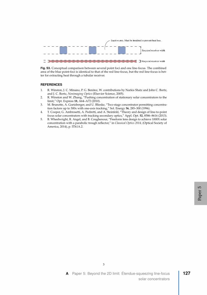
Fig. S3. Conceptual comparison between several point foci and one line-focus. The combinedarea of the blue point-foci is identical to that of the red line-focus, but the red line-focus is bet-ter for extracting heat through a tubular receiver.
REFERENCES
1. R. Winston, J. C. Minano, P. G. Benitez, W. contributions by Narkis Shatz and John C. Bortz,and J. C. Bortz, Nonimaging Optics (Elsevier Science, 2005).
2. R. Winston and W. Zhang, “Pushing concentration of stationary solar concentrators to thelimit,” Opt. Express 18, A64–A72 (2010).
3. M. Brunotte, A. Goetzberger, and U. Blieske, “Two-stage concentrator permitting concentra-tion factors up to 300x with one-axis tracking,” Sol. Energy 56, 285–300 (1996).
4. T. Cooper, G. Ambrosetti, A. Pedretti, and A. Steinfeld, “Theory and design of line-to-pointfocus solar concentrators with tracking secondary optics,” Appl. Opt. 52, 8586–8616 (2013).
5. B. Wheelwright, R. Angel, and B. Coughenour, “Freeform lens design to achieve 1000X solarconcentration with a parabolic trough reflector,” in Classical Optics 2014, (Optical Society ofAmerica, 2014), p. ITh1A.2.
3
Pape
r5
A Paper 5: Beyond the 2D limit: Étendue-squeezing line-focussolar concentrators
127
ISBN 978-82-471-9743-1 (printed ver.)ISBN 978-82-471-9791-2 (electronic ver.)
ISSN 1503-8181 (printed ver.)ISSN 2703-8084 (online ver.)
Doctoral theses at NTNU, 2020:405
Håkon J. D. Johnsen
New Approaches to SolarTracking and Concentrationthrough NumericalOptimization of Lens Arrays
Doc
tora
l the
sis
Doctoral theses at N
TNU
, 2020:405H
åkon J. D. Johnsen
NTN
UN
orw
egia
n U
nive
rsity
of S
cien
ce a
nd T
echn
olog
yTh
esis
for t
he D
egre
e of
Philo
soph
iae
Doc
tor
Facu
lty o
f Eng
inee
ring
Dep
artm
ent o
f Mec
hani
cal a
nd In
dust
rial
Engi
neer
ing