Developing a Software Product Line for Train Control: A Case Study of CVL
15
Developing a Software Product Line for Train Control: A Case Study of CVL Andreas Svendsen 2,3 , Xiaorui Zhang 2,3 , Roy Lind-Tviberg 1 , Franck Fleurey 2 , Øystein Haugen 2 , Birger Møller-Pedersen 3 , Gøran K. Olsen 2 , 1 ABB, Bergerveien 12, 1375 Billingstad, Norway [email protected] 2 SINTEF, Forskningsveien 1, Oslo, Norway {Andreas.Svendsen, Xiaorui.Zhang, Franck.Fleurey, Oystein.Haugen, Goran.K.Olsen}@sintef.no 3 Department of Informatics, University of Oslo, Oslo, Norway [email protected] Abstract. This paper presents a case study of creating a software product line for the train signaling domain. The Train Control Language (TCL) is a DSL which automates the production of source code for computers controlling train stations. By applying the Common Variability Language (CVL), which is a separate and generic language to define variability on base models, we form a software product line of stations. We discuss the process and experience of using CVL to automate the production of three real train stations. A brief discussion about the verification needed for the generated products is also included. 1 Introduction The Train Control Language (TCL) is a domain-specific language (DSL) for describing train stations in the train signaling domain. A DSL is a programming or modeling language dedicated to a particular problem domain. TCL is developed by SINTEF in cooperation with ABB, Norway, and contains a minimal but sufficient set of concepts within the train signaling domain. The purpose of TCL is to automate the production of source code that controls the signaling system on a station. Production of TCL stations can be further automated by using software product line (SPL) technology. An SPL captures the variabilities and commonalities of a series of products that are sufficiently similar. Product line modeling involves information about all product line members, which is different from modeling a singular product. The Common Variability Language (CVL) provides a generic and separate approach for modeling variability in models defined by DSLs such as TCL [5][4]. CVL can be applied to models in any DSL that is defined by a metamodel by means of Meta Object Facility (MOF) [7]. This paper presents a case study on how we
-
Upload
independent -
Category
Documents
-
view
0 -
download
0
Transcript of Developing a Software Product Line for Train Control: A Case Study of CVL
Developing a Software Product Line for Train Control: A Case Study of CVL
Andreas Svendsen2,3, Xiaorui Zhang2,3, Roy Lind-Tviberg1, Franck Fleurey2, Øystein Haugen2, Birger Møller-Pedersen3, Gøran K. Olsen2,
1 ABB, Bergerveien 12, 1375 Billingstad, Norway [email protected]
2 SINTEF, Forskningsveien 1, Oslo, Norway
{Andreas.Svendsen, Xiaorui.Zhang, Franck.Fleurey, Oystein.Haugen, Goran.K.Olsen}@sintef.no
3 Department of Informatics, University of Oslo, Oslo, Norway
Abstract. This paper presents a case study of creating a software product line for the train signaling domain. The Train Control Language (TCL) is a DSL which automates the production of source code for computers controlling train stations. By applying the Common Variability Language (CVL), which is a separate and generic language to define variability on base models, we form a software product line of stations. We discuss the process and experience of using CVL to automate the production of three real train stations. A brief discussion about the verification needed for the generated products is also included.
1 Introduction
The Train Control Language (TCL) is a domain-specific language (DSL) for describing train stations in the train signaling domain. A DSL is a programming or modeling language dedicated to a particular problem domain. TCL is developed by SINTEF in cooperation with ABB, Norway, and contains a minimal but sufficient set of concepts within the train signaling domain. The purpose of TCL is to automate the production of source code that controls the signaling system on a station.
Production of TCL stations can be further automated by using software product line (SPL) technology. An SPL captures the variabilities and commonalities of a series of products that are sufficiently similar. Product line modeling involves information about all product line members, which is different from modeling a singular product.
The Common Variability Language (CVL) provides a generic and separate approach for modeling variability in models defined by DSLs such as TCL [5][4]. CVL can be applied to models in any DSL that is defined by a metamodel by means of Meta Object Facility (MOF) [7]. This paper presents a case study on how we
2
applied CVL to TCL for developing a station product line where all the product line members are Norwegian train stations in use or under development. We report on the process of using CVL to express the variabilities and commonalities among designated products of the station product line, and how we derived and decided on the final product line based on that. We report on several issues that occurred during the development, discuss the pros and cons of different alternative solutions and report on our own experience trying out those solutions. Based on the experience of this case study, we also make some initial thoughts on the methodological support for the CVL approach and identify some open issues for future work.
The paper is structured as follows: Section 2 briefly presents the train domain, TCL and software product lines. Section 3 introduces CVL and its tool support, before Section 4 walks through the process of creating the station product line and the collected experiences from this assignment. Finally, Section 5 concludes with some open issues for future work.
2 Background
This section briefly introduces the train signaling domain and software product lines. TCL, as a DSL for this domain, was developed for the purpose of generating interlocking source code (functional blocks) for the Programmable Logic Circuit (PLC) at a station. TCL is used as the base language for our case study.
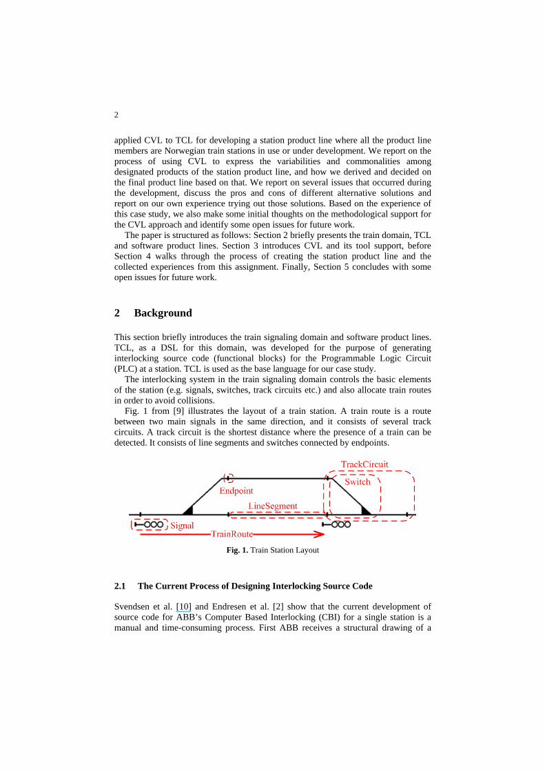
The interlocking system in the train signaling domain controls the basic elements of the station (e.g. signals, switches, track circuits etc.) and also allocate train routes in order to avoid collisions.
Fig. 1 from [9] illustrates the layout of a train station. A train route is a route between two main signals in the same direction, and it consists of several track circuits. A track circuit is the shortest distance where the presence of a train can be detected. It consists of line segments and switches connected by endpoints.
Fig. 1. Train Station Layout
2.1 The Current Process of Designing Interlocking Source Code
Svendsen et al. [10] and Endresen et al. [2] show that the current development of source code for ABB’s Computer Based Interlocking (CBI) for a single station is a manual and time-consuming process. First ABB receives a structural drawing of a
3
station with its interlocking table from the Norwegian Train Authorities, and then the train experts develop the functional specification and design specification. These are formally reviewed before two independent teams create the interlocking source code for the station based upon these specifications. This source code is then thoroughly tested.
The current development process is manual and time-consuming. This is the reason why model-driven development (MDD) is considered and TCL is developed.
2.2 Train Control Language
The TCL language is defined by an Ecore metamodel in the Eclipse Modeling Framework (EMF) [1] as explained by Svendsen et al. [10] and Endresen et al. [2]. Its tool support includes a graphical editor, a tree-view editor and code generators.
The use of TCL allows the train experts to only work on defining the station in the TCL graphical editor. The code generators will then produce other representations automatically, such as interlocking tables (truth tables) and interlocking source code. This source code, which is a form of functional blocks, is then loaded into the Programmable Logic Circuits (PLCs) for that station. The model-to-text code generator, written in MOFScript [8], requires adequate expertise in the train signaling domain and an overall understanding of interlocking source code on various train stations [10].
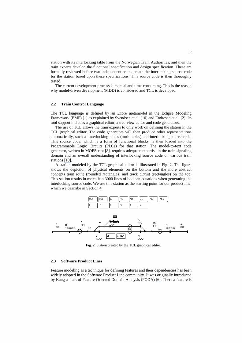
A station modeled by the TCL graphical editor is illustrated in Fig. 2. The figure shows the depiction of physical elements on the bottom and the more abstract concepts train route (rounded rectangles) and track circuit (rectangles) on the top. This station results in more than 3000 lines of boolean equations when generating the interlocking source code. We use this station as the starting point for our product line, which we describe in Section 4.
Fig. 2. Station created by the TCL graphical editor.
2.3 Software Product Lines
Feature modeling as a technique for defining features and their dependencies has been widely adopted in the Software Product Line community. It was originally introduced by Kang as part of Feature-Oriented Domain Analysis (FODA) [6]. There a feature is
4
defined for the first time as a “prominent or distinctive user-visible aspect, quality, or characteristic of a software system”. Feature modeling is a means to reflect user choices and requirements in an early phase of the product design.
Features are typically modeled in the form of tree-like feature diagrams along with cross-tree constraints. A Feature Diagram is considered to be an intuitive way to visually present the user choices of the features, and is therefore widely used and extended. The FODA notation includes child features as optional, mandatory or alternative (XOR).
3 Common Variability Language
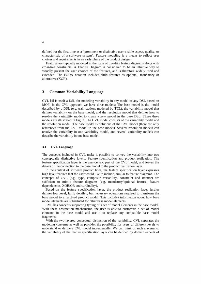
CVL [4] is itself a DSL for modeling variability in any model of any DSL based on MOF. In the CVL approach we have three models: The base model is the model described by a DSL (e.g. train stations modeled by TCL), the variability model that defines variability on the base model, and the resolution model that defines how to resolve the variability model to create a new model in the base DSL. These three models are illustrated in Fig. 3. The CVL model consists of the variability model and the resolution model. The base model is oblivious of the CVL model (there are only references from the CVL model to the base model). Several resolution models can resolve the variability in one variability model, and several variability models can describe the variability in one base model
3.1 CVL Language
The concepts included in CVL make it possible to convey the variability into two conceptually distinctive layers: Feature specification and product realization. The feature specification layer is the user-centric part of the CVL model, and leaves the details of the connection to the base model to the product realization layer. In the context of software product lines, the feature specification layer expresses high level features that the user would like to include, similar to feature diagrams. The concepts of CVL (e.g., type, composite variability, constraint and iterator) are sufficient to mimic feature diagrams (e.g. mandatory/optional feature, feature dependencies, XOR/OR and cardinality). Based on the feature specification layer, the product realization layer further defines low level, fairly detailed, but necessary operations required to transform the base model to a resolved product model. This includes information about how base model elements are substituted for other base model elements. CVL has concepts supporting typing of a set of model elements in the base model. With these abstraction mechanisms, the user is able to customize a set of model elements in the base model and use it to replace any compatible base model fragments.
With the two-layered conceptual distinction of the variability, CVL separates the modeling concerns as well as provides the possibility for users of different levels to understand or define a CVL model incrementally. We can think of such a scenario: the variability of the feature specification layer can be defined by domain experts of
5
higher level design, such as to identify features of product line members, while the variability of the product realization can be defined by domain experts who are more familiar with detailed design of the system.
DSL
Variationmodel
CVL
Base domain model
Generic & Standardized
resolutionmodels
Focused on a domain
Execute CVLTransformations
Resolved domain models
Description of possible
variations in the system
Domain model of a particular family of system
Selection of a set of options in the variation model
Family of systems fully described in the domain specific language.All regular DSL tools can be applied to these models
Fig. 3. CVL combining with a DSL
3.2 CVL Tool Support
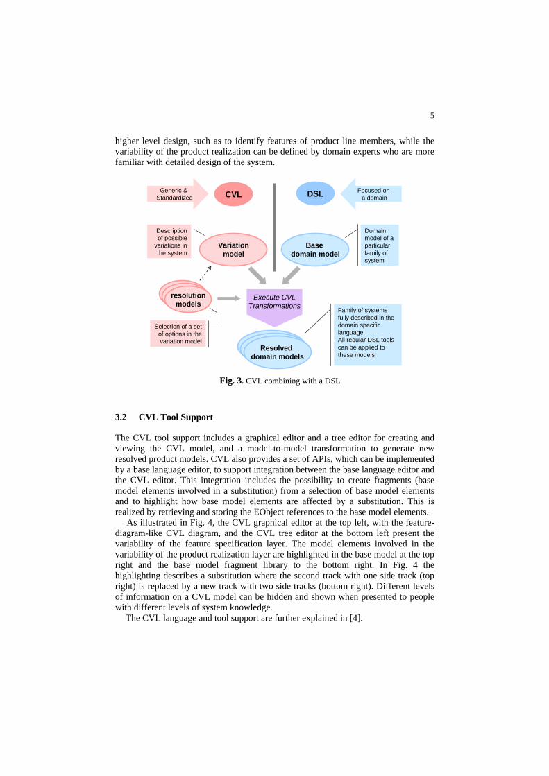
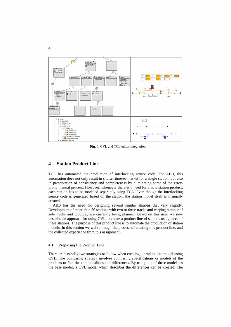
The CVL tool support includes a graphical editor and a tree editor for creating and viewing the CVL model, and a model-to-model transformation to generate new resolved product models. CVL also provides a set of APIs, which can be implemented by a base language editor, to support integration between the base language editor and the CVL editor. This integration includes the possibility to create fragments (base model elements involved in a substitution) from a selection of base model elements and to highlight how base model elements are affected by a substitution. This is realized by retrieving and storing the EObject references to the base model elements. As illustrated in Fig. 4, the CVL graphical editor at the top left, with the feature-diagram-like CVL diagram, and the CVL tree editor at the bottom left present the variability of the feature specification layer. The model elements involved in the variability of the product realization layer are highlighted in the base model at the top right and the base model fragment library to the bottom right. In Fig. 4 the highlighting describes a substitution where the second track with one side track (top right) is replaced by a new track with two side tracks (bottom right). Different levels of information on a CVL model can be hidden and shown when presented to people with different levels of system knowledge.
The CVL language and tool support are further explained in [4].
6
Fig. 4. CVL and TCL editor integration
4 Station Product Line
TCL has automated the production of interlocking source code. For ABB, this automation does not only result in shorter time-to-market for a single station, but also in preservation of consistency and completeness by eliminating some of the error-prone manual process. However, whenever there is a need for a new station product, each station has to be modeled separately using TCL. Even though the interlocking source code is generated based on the station, the station model itself is manually created.
ABB has the need for designing several similar stations that vary slightly. Development of more than 20 stations with two or three tracks and varying number of side tracks and topology are currently being planned. Based on this need we now describe an approach for using CVL to create a product line of stations using three of these stations. The purpose of this product line is to automate the production of station models. In this section we walk through the process of creating this product line, and the collected experience from this assignment.
4.1 Preparing the Product Line
There are basically two strategies to follow when creating a product line model using CVL. The comparing strategy involves comparing specifications or models of the products to find the commonalities and differences. By using one of these models as the base model, a CVL model which describes the differences can be created. The
7
constructive strategy involves selecting a base model as a starting point, and defining the product specifics directly in CVL. The last strategy can be advantageous if well-defined products do not exist when preparing the product line.
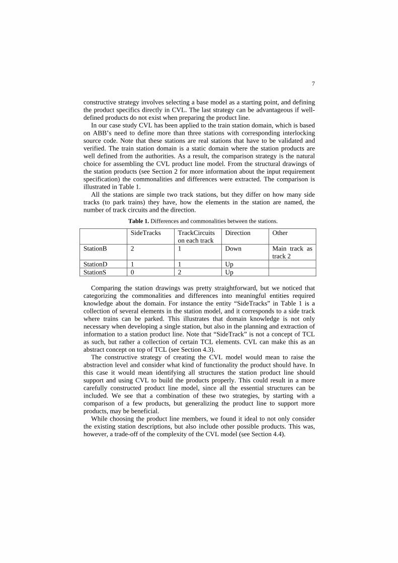
In our case study CVL has been applied to the train station domain, which is based on ABB’s need to define more than three stations with corresponding interlocking source code. Note that these stations are real stations that have to be validated and verified. The train station domain is a static domain where the station products are well defined from the authorities. As a result, the comparison strategy is the natural choice for assembling the CVL product line model. From the structural drawings of the station products (see Section 2 for more information about the input requirement specification) the commonalities and differences were extracted. The comparison is illustrated in Table 1.
All the stations are simple two track stations, but they differ on how many side tracks (to park trains) they have, how the elements in the station are named, the number of track circuits and the direction.
Table 1. Differences and commonalities between the stations.
SideTracks TrackCircuits on each track
Direction Other
StationB 2 1 Down Main track as track 2
StationD 1 1 Up StationS 0 2 Up
Comparing the station drawings was pretty straightforward, but we noticed that categorizing the commonalities and differences into meaningful entities required knowledge about the domain. For instance the entity “SideTracks” in Table 1 is a collection of several elements in the station model, and it corresponds to a side track where trains can be parked. This illustrates that domain knowledge is not only necessary when developing a single station, but also in the planning and extraction of information to a station product line. Note that “SideTrack” is not a concept of TCL as such, but rather a collection of certain TCL elements. CVL can make this as an abstract concept on top of TCL (see Section 4.3).
The constructive strategy of creating the CVL model would mean to raise the abstraction level and consider what kind of functionality the product should have. In this case it would mean identifying all structures the station product line should support and using CVL to build the products properly. This could result in a more carefully constructed product line model, since all the essential structures can be included. We see that a combination of these two strategies, by starting with a comparison of a few products, but generalizing the product line to support more products, may be beneficial.
While choosing the product line members, we found it ideal to not only consider the existing station descriptions, but also include other possible products. This was, however, a trade-off of the complexity of the CVL model (see Section 4.4).
8
4.2 Choosing a Base Model
As presented in Section 3, the CVL model defines how a base model can vary. The execution of a CVL model will perform a model-to-model transformation from this base model to a new base model defined by the same metamodel. To define a station product line in CVL, it is required to have a station base model as a starting point.
There are several strategies for choosing such a base model. Since CVL replaces values and sets of model elements, executing CVL can add, remove or replace functionality. One obvious choice of base model can be a model with maximum set of features included, meaning a complete model where CVL can remove features to get a specific product model. In other words when we operate on a maximum base model a subtractive strategy is used. Another choice of base model can be a model with minimum set of features included in the model itself, and other fragments in other library models (more about CVL library in Section 4.3). Then the product models will be generated by adding features to the base model. An additive strategy will thus be used when operating on a minimum base model. A third strategy is to choose a base model that has neither maximum nor minimum, but somewhere in between. This base model can for instance be the base model that is most similar to the majority of the product models, or a base model that is tailored for teaching purposes. This can be viewed as operating on an intermediate base model, where both additive and subtractive strategies will be used. One choice of an intermediate base model may be the one that results in the most compact CVL model. A compact CVL model can be measured in the number of substitutions and the complexity of the fragments used in the substitutions (e.g. number of boundary elements involved, where a boundary element in CVL records a reference into or out of the fragment). A compact CVL model can be easier to maintain.
As mentioned in Section 3, CVL supports a division between the feature specification layer and the product realization layer, where the connection to the base model resides only in the product realization layer. The feature specification layer is independent of the chosen base model and does therefore not depend on the strategy for choosing a base model. However, this requires the naming policy of the feature specification layer to be independent of whether an additive or subtractive strategy is used (e.g. “No SideTrack” instead of “RemoveSideTrack”). The product realization layer will use substitutions with additive or subtractive strategies based on the kind of base model that is used.
Furthermore, in TCL the base model can either be a complete product that will be one of the products of the product line, or it can be an incomplete product that will be transformed to a valid product by CVL. Whether to use a complete product as a base model depends on the base language and on the choice of strategy for selecting a base model.
When creating the station product line we decided to follow the intermediate base model strategy, by choosing a base model that has neither maximum nor minimum set of features. Fig. 2 illustrates StationD, which we used as the base model for this product line. This station has been manually modeled in the TCL graphical editor. The reason for choosing this as a base model was to keep the base model as similar to all the product models as possible. The number of substitutions and the complexity of the substitutions can therefore be kept at a minimum.
9
Our experience shows that since CVL is based on substitutions on the base model, an intermediate base model which is similar to the product models can result in a simpler CVL model with fewer substitutions. However, there may in some cases be advantageous to use a maximum or a minimum base model. Using a minimum base model can ease the process of evolving the product line if new product models are required. New features can then be added to the minimum base model in a straightforward way to produce a new product model. A strategy using a maximum base model depends less on the use of library models, and may ease the maintenance of the base model and library models themselves.
4.3 CVL Library
CVL creates a product model by copying the base model and performing the selected substitutions. When a set of base model elements is replaced by another set of base model elements a copy is made of the second set of base model elements. This implies that the replacing set of base model elements can either originate in the base model itself or in another model, e.g. in a library. If the minimal base model strategy is used, some model elements, not already in the base model, may have to be added. This requires such a library where the additional model elements can be found.
A library can either consist of complete models where a set of model fragments is extracted, or it can be partial models with only the fragments themselves. In our case this library could either consist of complete stations where some model fragments are extracted (e.g. a side track), or the necessary fragments could be detached in a model.
TCL itself does not have any concepts for structuring model elements (e.g. side track). However, CVL can define fragments in the base language by recording references to and from base model elements inside the fragment. By defining types in CVL, these fragments of base model elements can be given an entity that can be configured and reused. Furthermore, these types can be given names that originate from the base language (e.g. “Additional TrackCircuit”). These fragments and types will therefore define base model elements from a set of library models that can be used in substitutions on the base model.
Our strategy for this product line was to create a dedicated fragment model, where all the necessary fragments were stored. The reason for this choice was the lack of other complete models with the fragments needed for the products. The fragment model is illustrated in the lower right of Fig. 4. This resulted in missing context for the fragments, yielding more work connecting the model elements together. Therefore, by rather selecting model elements from a library of complete stations, connecting the tracks together would have been more straightforward. However, this will require the library to either have several stations with all kinds of fragments or one complete station which contains every necessary fragment. This may not be practical since we may want to create a product with a new kind of fragment, and creating a complete new station in the library for this purpose defeats some of the intention of the product line.
We noticed that if a fragment model is used it is helpful to model the immediate context around the model elements in the fragment, to automate the process of connecting the model elements. However, this requires detailed knowledge of the
10
base language and what kind of context that is necessary. For this reason, complete models may be a better choice for the library.
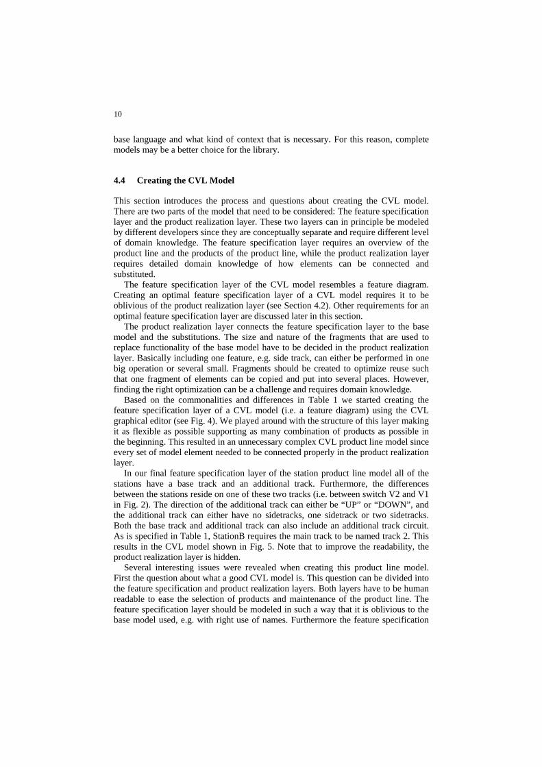
4.4 Creating the CVL Model
This section introduces the process and questions about creating the CVL model. There are two parts of the model that need to be considered: The feature specification layer and the product realization layer. These two layers can in principle be modeled by different developers since they are conceptually separate and require different level of domain knowledge. The feature specification layer requires an overview of the product line and the products of the product line, while the product realization layer requires detailed domain knowledge of how elements can be connected and substituted.
The feature specification layer of the CVL model resembles a feature diagram. Creating an optimal feature specification layer of a CVL model requires it to be oblivious of the product realization layer (see Section 4.2). Other requirements for an optimal feature specification layer are discussed later in this section.
The product realization layer connects the feature specification layer to the base model and the substitutions. The size and nature of the fragments that are used to replace functionality of the base model have to be decided in the product realization layer. Basically including one feature, e.g. side track, can either be performed in one big operation or several small. Fragments should be created to optimize reuse such that one fragment of elements can be copied and put into several places. However, finding the right optimization can be a challenge and requires domain knowledge.
Based on the commonalities and differences in Table 1 we started creating the feature specification layer of a CVL model (i.e. a feature diagram) using the CVL graphical editor (see Fig. 4). We played around with the structure of this layer making it as flexible as possible supporting as many combination of products as possible in the beginning. This resulted in an unnecessary complex CVL product line model since every set of model element needed to be connected properly in the product realization layer.
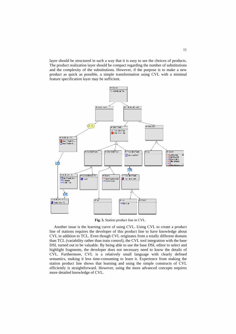
In our final feature specification layer of the station product line model all of the stations have a base track and an additional track. Furthermore, the differences between the stations reside on one of these two tracks (i.e. between switch V2 and V1 in Fig. 2). The direction of the additional track can either be “UP” or “DOWN”, and the additional track can either have no sidetracks, one sidetrack or two sidetracks. Both the base track and additional track can also include an additional track circuit. As is specified in Table 1, StationB requires the main track to be named track 2. This results in the CVL model shown in Fig. 5. Note that to improve the readability, the product realization layer is hidden.
Several interesting issues were revealed when creating this product line model. First the question about what a good CVL model is. This question can be divided into the feature specification and product realization layers. Both layers have to be human readable to ease the selection of products and maintenance of the product line. The feature specification layer should be modeled in such a way that it is oblivious to the base model used, e.g. with right use of names. Furthermore the feature specification
11
layer should be structured in such a way that it is easy to see the choices of products. The product realization layer should be compact regarding the number of substitutions and the complexity of the substitutions. However, if the purpose is to make a new product as quick as possible, a simple transformation using CVL with a minimal feature specification layer may be sufficient.
Fig. 5. Station product line in CVL.
Another issue is the learning curve of using CVL. Using CVL to create a product line of stations requires the developer of this product line to have knowledge about CVL in addition to TCL. Even though CVL originates from a totally different domain than TCL (variability rather than train control), the CVL tool integration with the base DSL turned out to be valuable. By being able to use the base DSL editor to select and highlight fragments, the developer does not necessary need to know the details of CVL. Furthermore, CVL is a relatively small language with clearly defined semantics, making it less time-consuming to learn it. Experience from making the station product line shows that learning and using the simple constructs of CVL efficiently is straightforward. However, using the more advanced concepts requires more detailed knowledge of CVL.

12
Since CVL is a separate language to model variability, knowledge about CVL is not specific to TCL, meaning that this knowledge can be used if there is a need to develop product line models for other DSLs.
4.5 Generating Products
A CVL model does not only include the feature specification layer with information about features, but also the product realization layer with information about how to generate specific products. The resolution model can then choose which substitutions to execute. Executing the CVL model will generate specific products (i.e. station models).
From the station product line illustrated in Fig. 5 several more than the three real target stations can be generated by carefully making another selection of features in the CVL model. For now, we are only interested in three specific products; StationB, StationD and StationS. We therefore define three resolutions to the variability model and run the CVL execution engine, which gives us the three stations mentioned. StationD is illustrated in Fig. 2, StationB in Fig. 6 and StationS in Fig. 7. Note that when the CVL model (including resolutions) is specified, the generation of the products is performed automatically. New station models are generated, and their diagrams are initialized.
Fig. 6. StationB generated from CVL.
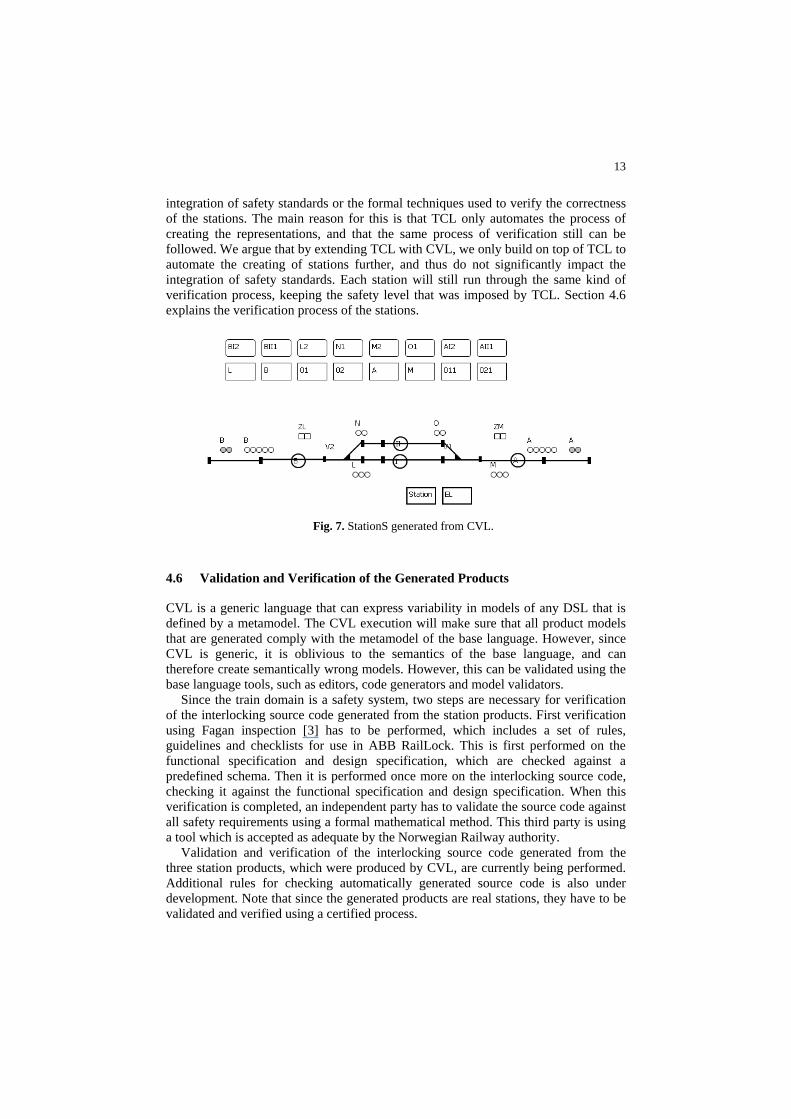
The generated StationB has two side tracks and has direction set to “DOWN”. The names of the tracks have also been changed to realize that track 2 is the main track. In the generation of StationS, two track circuits (011 and 021) have been added (i.e. rectangles representing track circuits). This can also be seen by looking at the extra line segments and endpoints on the two tracks. In addition StationS has no side tracks.
From the generated product models, the TCL code generators can be used to generate interlocking source code and interlocking tables. For each of the three products we have generated these representations and they are being validated by the signaling experts working at ABB (see Section 4.6).
Svendsen et al. [10] claim that the usage of TCL to generate interlocking source code and other representations of a station does not significantly impact the
13
integration of safety standards or the formal techniques used to verify the correctness of the stations. The main reason for this is that TCL only automates the process of creating the representations, and that the same process of verification still can be followed. We argue that by extending TCL with CVL, we only build on top of TCL to automate the creating of stations further, and thus do not significantly impact the integration of safety standards. Each station will still run through the same kind of verification process, keeping the safety level that was imposed by TCL. Section 4.6 explains the verification process of the stations.
Fig. 7. StationS generated from CVL.
4.6 Validation and Verification of the Generated Products
CVL is a generic language that can express variability in models of any DSL that is defined by a metamodel. The CVL execution will make sure that all product models that are generated comply with the metamodel of the base language. However, since CVL is generic, it is oblivious to the semantics of the base language, and can therefore create semantically wrong models. However, this can be validated using the base language tools, such as editors, code generators and model validators.
Since the train domain is a safety system, two steps are necessary for verification of the interlocking source code generated from the station products. First verification using Fagan inspection [3] has to be performed, which includes a set of rules, guidelines and checklists for use in ABB RailLock. This is first performed on the functional specification and design specification, which are checked against a predefined schema. Then it is performed once more on the interlocking source code, checking it against the functional specification and design specification. When this verification is completed, an independent party has to validate the source code against all safety requirements using a formal mathematical method. This third party is using a tool which is accepted as adequate by the Norwegian Railway authority.
Validation and verification of the interlocking source code generated from the three station products, which were produced by CVL, are currently being performed. Additional rules for checking automatically generated source code is also under development. Note that since the generated products are real stations, they have to be validated and verified using a certified process.
14
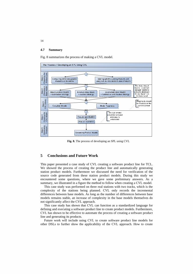
4.7 Summary
Fig. 8 summarizes the process of making a CVL model.
Step
2:
Cho
osin
g a
Base
Mod
el
Ste
p 3:
C
VL L
ibra
ry
Ste
p 4:
C
reat
ing
the
CV
L M
odel
Ste
p 5:
G
ener
atin
g Pr
oduc
ts
Step
1:
Pre
parin
g th
e Pr
oduc
t Lin
e
Fig. 8. The process of developing an SPL using CVL
5 Conclusions and Future Work
This paper presented a case study of CVL creating a software product line for TCL. We showed the process of creating the product line and automatically generating station product models. Furthermore we discussed the need for verification of the source code generated from these station product models. During this study we encountered some questions, where we gave some preliminary answers. As a summary, we illustrated in a figure the method to follow when creating a CVL model.
This case study was performed on three real stations with two tracks, which is the complexity of the stations being planned. CVL only records the incremental differences between base models. As long as the number of differences between base models remains stable, an increase of complexity in the base models themselves do not significantly affect the CVL approach.
This case study has shown that CVL can function as a standardized language for defining and executing a software product line to create product models. Furthermore, CVL has shown to be effective to automate the process of creating a software product line and generating its products.
Future work will include using CVL to create software product line models for other DSLs to further show the applicability of the CVL approach. How to create
15
op
odel [11]. Automating the evolution of
sented here has been developed within the MoSiS roject ITEA 2 – ip06035 part of the Eureka framework.
References
Modeling Framework Project (Emf).” http://www.eclipse.org/modeling/emf/ 2. Endresen, J., Carlson, E., Moen, T., Alme, K.-J., Haugen, Ø., Olsen, G.K., and Svendsen, A.,
8.
timal CVL models, both on the feature specification and product realization layer, is also an issue that will be further investigated.
Other work that is also in progress is an automated approach for comparing a set of base models and deriving the CVL product line m
test-cases corresponding to base models is also being investigated [9]. We believe that such incremental analysis for safely avoiding retest of test-cases will give a huge benefit and return on investment. Acknowledgments. The work prep
1. EMF, “Eclipse
“Train Control Language - Teaching Computers Interlocking,” Computers in Railways XI(COMPRAIL 2008), Toledo, Spain, (2008)
3. Fagan, M.E.: Design and Code Inspections to Reduce Errors in Program Development. IBM Systems Journal. 15, 182-211 (1976)
4. Fleurey, F., Haugen, Ø., Møller-Pedersen, B., Olsen, G.K., Svendsen, A., and Zhang, X., “A Generic Language and Tool for Variability Modeling,” SINTEF, Oslo, Norway, Technical Report SINTEF A13505, (2009),
5. Haugen, O., Møller-Pedersen, B., Oldevik, J., Olsen, G.K., and Svendsen, A., “Adding Standardized Variability to Domain Specific Languages,” SPLC 2008, Limerick, Ireland, (2008)
6. Kang, K., Cohen, S., Hess, J., Novak, W., and Peterson, A., “Feature-Oriented Domain Analysis (Foda) Feasibility Study,” Software Engineering Institute, Carnegie Mellon University, Pittsburgh, PA Tech. Report CMU/SEI-90-TR-21, Nov., (1990),
7. MOF, “The Metaobject Facility Specification.” http://www.omg.org/mof/ Oldevik, J., “Mofscript Eclipse Plug-In: Metamodel-Based Code Generation.,” in Eclipse Technology Workshop (EtX) at ECOOP 2006. Nantes, (2006)
9. Svendsen, A., “Application Reconfiguration Based on Variability Transformations,” School of Computing, Queen’s University, Kingston, Canada, Technical Report 2009-566, (2009),
10. Svendsen, A., Olsen, G.K., Endresen, J., Moen, T., Carlson, E., Alme, K.-J., and Haugen, O., “The Future of Train Signaling,” Model Driven Engineering Languages and Systems (MoDELS 2008), Tolouse, France, (2008)
11. Zhang, X., “Synthesize Software Product Line,” the 32nd international conference on software engineering, Cape Town, South Africa, (2010)