Determining the R values for 12 inch deep Z-purlins and girts ...
71
Scholars' Mine Masters eses Student Research & Creative Works Summer 2010 Determining the R values for 12 inch deep Z- purlins and girts with through-fastened panels under suction loading Kaye Dee Wibbenmeyer Follow this and additional works at: hp://scholarsmine.mst.edu/masters_theses Part of the Civil Engineering Commons Department: Civil, Architectural and Environmental Engineering is esis - Open Access is brought to you for free and open access by the Student Research & Creative Works at Scholars' Mine. It has been accepted for inclusion in Masters eses by an authorized administrator of Scholars' Mine. For more information, please contact [email protected]. Recommended Citation Wibbenmeyer, Kaye Dee, "Determining the R values for 12 inch deep Z-purlins and girts with through-fastened panels under suction loading" (2010). Masters eses. Paper 6924.
-
Upload
khangminh22 -
Category
Documents
-
view
1 -
download
0
Transcript of Determining the R values for 12 inch deep Z-purlins and girts ...

Scholars' Mine
Masters Theses Student Research & Creative Works
Summer 2010
Determining the R values for 12 inch deep Z-purlins and girts with through-fastened panelsunder suction loadingKaye Dee Wibbenmeyer
Follow this and additional works at: http://scholarsmine.mst.edu/masters_theses
Part of the Civil Engineering CommonsDepartment: Civil, Architectural and Environmental Engineering
This Thesis - Open Access is brought to you for free and open access by the Student Research & Creative Works at Scholars' Mine. It has been acceptedfor inclusion in Masters Theses by an authorized administrator of Scholars' Mine. For more information, please contact [email protected].
Recommended CitationWibbenmeyer, Kaye Dee, "Determining the R values for 12 inch deep Z-purlins and girts with through-fastened panels under suctionloading" (2010). Masters Theses. Paper 6924.


2
DETERMINING THE R VALUES FOR 12 INCH DEEP Z-PURLINS AND GIRTS WITH THROUGH-FASTENED PANELS UNDER SUCTION LOADING
by
KAYE DEE WIBBENMEYER
A THESIS
Presented to the Faculty of the Graduate School of the
MISSOURI UNIVERSITY OF SCIENCE AND TECHNOLOGY
In Partial Fulfillment of the Requirements for the Degree
MASTER OF SCIENCE IN CIVIL ENGINEERING
2010
Approved by
Dr. Roger LaBoube, Advisor Dr. Wei-Wen Yu Dr. Victor Birman

ii

iii
ABSTRACT
Designing purlins for roof systems attached to through-fastened panels has been a
subject well researched in the past. The current design specification uses a simplified
approach to the designing of these members where the fully braced moment capacity of
such members is multiplied by a reduction factor, commonly referred to as the R-value.
This value represents the point in between the fully braced and fully unbraced member
behavior. However, the current AISI Specification, S100, only contains R-values for
purlins and girts up to 11.5 inches in depth. Since manufacturers are now rolling sections
up to 12 inches deep, two confirmatory tests were performed with the goal of expanding
the limits of the current design provisions. The intent of this research was to demonstrate
that the R-value for the 11.5 inch deep Zee members is representative for members with
depths of 12 inches as well. One continuous span and one simple span test were
performed.
Based on the findings of this test program, 12” deep Z-purlins do meet or exceed
the required strength computed using the current AISI S100 R-values. Thus, it is
recommended that the limitations of Section D6.1.1 be expanded to include these deeper
12” Z-purlins. With the increase in depth, the depth-to-flange width ratio should also be
expanded. It is recommended that the upper limit of the depth-to flange width ratio be
expanded to include members with depth/flange width ratios up to a value of 5.5. It is
also recommended that Section D6.1.1 be changed to ensure ductile steel rather than
limiting the yield stress of the material. It is suggested that the limiting Fu/Fy ratio of the
member be 1.20.

iv
ACKNOWLEDGMENTS
I would like to take this opportunity to thank Dr. LaBoube, for all of his guidance
and support he has given me throughout my college career. It has been an awesome
experience to work with someone with so much knowledge and passion towards the
subject of cold-formed steel.
I would also like to thank all of those who financially supported me throughout
my graduate studies. In particular, NCI Building Systems for the donation of all the
materials needed to fabricate the tests, the use of their testing facility in Houston, Texas,
and also for the time and labor they put into helping with this testing. GTA support from
the Department of Civil, Architectural and Environmental Engineering at Missouri
University of Science and Technology is also greatly appreciated.
I would like to express gratitude to Dr. Yu for the Wei-Wen Yu Civil Engineering
Graduate Fellowship and for serving as a member on my thesis committee and Dr.
Birman for serving on my thesis committee as well. I would like to thank everyone
involved in making the experience of spending a semester abroad at Politecnico di
Milano in Milan, Italy possible for me specifically Dr. Carlo Castiglioni and and the
National Science Foundation for financial support.
I would also like to mention my family and friends, including my parents, David
and Cecilia, as well as, my brothers and sister, Ben, Elaine and Neil. They are sincerely
cherished.

v
TABLE OF CONTENTS
Page
ABSTRACT ....................................................................................................................... iii
ACKNOWLEDGMENTS ................................................................................................ iv
LIST OF FIGURES .......................................................................................................... vii
LIST OF TABLES ........................................................................................................... viii
SECTION
1. INTRODUCTION .....................................................................................................1
1.1. GENERAL .........................................................................................................1
1.2. APPLICATION ..................................................................................................2
2. LITERATURE REVIEW ..........................................................................................3
2.1. GENERAL .........................................................................................................3
2.2 PREVIOUS RESEARCH....................................................................................3
2.2.1. Haussler and Pabers, 1973 .........................................................................3
2.2.2. Pekoz and Soroushian, 1981 and 1982 ......................................................5
2.2.3. LaBoube, 1986 ..........................................................................................5
2.2.4. Haussler, 1988 ...........................................................................................7
2.2.5. LaBoube, et al., 1988 .................................................................................7
2.2.6. Fisher, 1996 ...............................................................................................8
2.3. AISI DESIGN PROVISIONS ............................................................................9
2.3.1. AISI Specification 1980 Edition ...............................................................9
2.3.2. Cold-Formed Steel Specification 1986 Edition .........................................9
2.3.3. Cold-Formed Steel Design Specification 1996 Edition ............................9
2.3.4. Cold-Formed Steel Design Specification 2001 Edition ..........................10
2.3.5. AISI Specification 2007 Edition Section D6.1.1. ...................................10
2.4. EUROPEAN DESIGN PROVISIONS ............................................................12
2.4.1 Design Provisions. ....................................................................................12
2.4.2 Comparison to Other Literature ...............................................................20
3. EXPERIMENTAL INVESTIGATION ...................................................................21
3.1. INTRODUCTION ............................................................................................21
3.2. SCOPE OF INVESTIGATION........................................................................21

vi
3.3. TEST PARAMETERS .....................................................................................21
3.4. TEST SETUP ...................................................................................................24
3.4.1. Test Fixture ..............................................................................................24
3.4.2. Test Specimens ........................................................................................30
4. TEST PROCEDURE ...............................................................................................32
4.1. INTRODUCTION ............................................................................................32
4.2. CHAMBER LOADING PROCEDURE ..........................................................32
5. TEST RESULTS ......................................................................................................33
5.1. INTRODUCTION ............................................................................................33
5.2. MATERIAL TESTING ....................................................................................33
5.3. SIMPLE SPAN TEST RESULTS ....................................................................34
5.4. CONTINUOUS SPAN TEST RESULTS ........................................................36
6. ANALYSIS OF TEST RESULTS ...........................................................................38
6.1. INTRODUCTION ............................................................................................38
6.2. SIMPLE SPAN TEST RESULT ANALYSIS .................................................38
6.3. CONTINUOUS SPAN TEST RESULT ANALYSIS .....................................38
7. CONCLUSIONS AND RECOMMENDATIONS ..................................................39
7.1. CONCLUSIONS ..............................................................................................39
7.2. RECOMMENDATIONS .................................................................................39
8. RECOMMENDATIONS FOR FUTURE RESEARCH ..........................................41
APPENDICES
A. EFFECTS OF RECOGNIZING PARTIAL BRACING PROVIDED BY THROUGH-FASTENED SHEATHING ................................................................42
B. GRAPHICAL RESULTS FROM LABOUBE’S “ROOF PANEL TO PURLIN CONNECTION: ROTATIONAL RESTRAINT FACTOR” REPORT (LaBoube 1986) .......................................................................................................45
C. FULL DETAIL OF PBR PANELING ....................................................................50
D. SUMMARY TABLE OF TEST RESULTS ...........................................................52
E. STATISTICAL ANALYSIS ...................................................................................54
F. Fu/Fy RATIO TABLE ..............................................................................................56
BIBLIOGRAPHY ..............................................................................................................58
VITA ...............................................................................................................................60

vii
LIST OF FIGURES
Figure Page
1.1. Metal Building Roof System ...................................................................................1
2.1. Distortion of Purlins Subject to Uplift Loading .....................................................12
2.2. Total Deformation Split into Two Parts.................................................................13
2.3. Model Purlin as Laterally Braced with Rotational Spring Restraint CD from Sheeting..................................................................................................................13
2.4. Rotational Spring Simplified by a Lateral Spring Stiffness K ...............................13
2.5. Free Flange Modeled as a Spring on an Elastic Foundation ..................................13
2.6. Internal Moment and Correction Factor ................................................................16
3.1. Flange-Bolted Connection .....................................................................................22
3.2. MBCI’s PBR Roof Panel Profile ...........................................................................23
3.3. Simple Span Chamber............................................................................................24
3.4. Simple Span Chamber Sketch ................................................................................25
3.5. Continuous Span Chamber ....................................................................................25
3.6. Continuous Span Chamber Sketch.........................................................................25
3.7. Chamber-to-Floor Connection ...............................................................................26
3.8. Support Beam to Chamber Connection .................................................................26
3.9. Purlin to Support Beam Connection ......................................................................27
3.10. Continuous Span Typical Lap Connection ............................................................27
3.11. Six Mil. Polyethylene Plastic .................................................................................28
3.12. Sixty Mil. EDPM Lining and Angle Connections .................................................28
3.13. Determination of Tributary Width .........................................................................29
3.14. Deflection Gauges ..................................................................................................29
3.15. Compressor Hookup ..............................................................................................30
3.16. Cross-Sectional Shape ...........................................................................................31
5.1. Typical Purlin Failure ............................................................................................33
5.2. Stress-Strain Curve ................................................................................................34
5.3. Simple Span Test Deflections ................................................................................34
5.4. Continuous Span Test Deflections .........................................................................36

viii
LIST OF TABLES
Table Page
2.1. Resulting R-Values from Fisher’s Study .................................................................8
2.2. AISI 1986 Edition R-Values ....................................................................................9
2.3. AISI 2001 Edition Simple Span R-Values.............................................................10
2.4. AISI 2007 Edition Simple Span R-Values.............................................................11
2.5. C100 and BT,max Values ............................................................................................19
3.1. Test Purlin Dimensions ..........................................................................................31
4.1. Test Pressure Intervals ...........................................................................................32

1
1. INTRODUCTION
1.1. GENERAL
The metal building industry uses C- and Z-purlins and girts as part of a system
connecting panels to the metal building’s main structure. These members are flexural
members with either screw attached or standing seam panels. A photo, courtesy of NCI
Building Systems, of such a roof system is shown in Figure 1.1. When a purlin or girt is
under wind suction, the compression flange of this member is not fully braced by the
panels. However, the purlin or girt is also not completely unbraced. The member has a
capacity somewhere in between these two extremes. Early research has shown how
complex a set of formulas can be when trying to mathematically model the rotational
restraint and distortion of the purlin-to-panel connections. A simpler approach is now
used by the cold-formed design community.
Figure 1.1. Metal Building Roof System
The design provisions used today are based on the fully braced purlin capacity
under uplift conditions. This capacity is then multiplied by a reduction factor based on

2
the size and shape of the member under loading. This reduction factor is call the R-value
and is based on experimental test results. The R-value represents that the system’s
bending strength lies in between fully braced and fully unbraced. The current AISI
specification (S100) provision only list R-values for purlins or girts with screw attached
panels.
1.2. APPLICATION
When the previous sets of continuous span and simple span R-value tests were
performed, metal building companies were not using Z-purlins as large as in today’s
industry. Several metal building manufactures are now using 12” deep Z-purlins and
girts. Since the American Iron and Steel Institute’s North American Specification for
Cold-Formed Steel Structural Members (2007) does not currently include R-values for
12” deep Z-sections, tests were completed to confirm that these deeper members have R-
values which fit within the range of previous tests for Z-section that had shallower
depths. Continuous and simple span tests were conducted as part of this study. These
tests were to be considered confirmatory tests if the results did, in fact, fit within the data
which supports current R-values. If the deeper members did not meet or exceed the
strength required for the current provisions for smaller sections, more tests would need to
be performed and new R-values for the deeper sections would be required to better
represent 12” deep members.

3
2. LITERATURE REVIEW
2.1 GENERAL
Prior to 1986, flexural members having one flange through-fastened to deck or
sheathing were designed as laterally unsupported members. This was highly conservative
and several approaches were researched to determine what factors affected the bracing
support gained by the through-fastened panel and to what degree were, in fact, the purlins
supported by the panel or deck. In other words, what capacity between fully braced and
laterally unbraced were the members reaching? Early design approaches were shown to
be quite complex and tests results deviated significantly from calculations. The current
provision, the North American Specification for the Design of Cold-Formed Steel
Structural Members (AISI S100) uses a simpler approach to determining the design
strength of Z-purlins and girts under uplift loading conditions.
Calculations in Appendix A show an example of how much design strength can
be gained when taking into account that the roof sheathing is providing some support for
the purlins. Section C.3.1.2 of the AISI S100 was used to calculate the fully unbraced
moment capacity, while Section D.6.1.1 was used to calculate the moment capacity with
the support gained from the through fasten roof sheathing taken into account.
2.2. PREVIOUS RESEARCH
The current design provisions contained in the AISI S100 Section D6.1.1 are
based primarily on the research programs summarized by Fisher (1996) and LaBoube et
al. (1988). The S100 gives R-values for through-fastened roof panels only. For systems
with standing seam panels, designers are referred to either Appendix A or B for
provisions. For the United States and Mexico, the Reduction factor must be determined
in accordance with the AISI S908 test method (AISI S908, 2004) also referred to as the
Base Test Method.
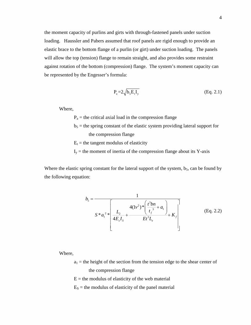
2.2.1 Haussler and Pabers, 1973. The paper “Connection Strength in Thin
Metal Roof Structures,” among other things, presents an analytical method for evaluating
4
the moment capacity of purlins and girts with through-fastened panels under suction
loading. Haussler and Pabers assumed that roof panels are rigid enough to provide an
elastic brace to the bottom flange of a purlin (or girt) under suction loading. The panels
will allow the top (tension) flange to remain straight, and also provides some restraint
against rotation of the bottom (compression) flange. The system’s moment capacity can
be represented by the Engesser’s formula:
(Eq. 2.1)
Where,
Pa = the critical axial load in the compression flange
b5 = the spring constant of the elastic system providing lateral support for
the compression flange
Et = the tangent modulus of elasticity
Iy = the moment of inertia of the compression flange about its Y-axis
Where the elastic spring constant for the lateral support of the system, b5, can be found by
the following equation:
(Eq. 2.2)
Where,
a1 = the height of the section from the tension edge to the shear center of
the compression flange
E = the modulus of elasticity of the web material
ES = the modulus of elasticity of the panel material
5 32
132 2
1 3
1
4(1 )** *
4f
fs S e
bt bnv atLS a K
E I Et L
=
+ + +
a 5 t yP =2 b E I

5
IS = the moment of inertia of the panel about its horizontal axis
KF = the experimentally determined joint flexibility in radians/inch lb
Le = the effective length of the web at each panel
L2 = the beam spacing
N = zero for unlipped flanges, 1 for lipped channels or zee sections, and
0.25 for lipped I sections
S = panel spacing
t = web thickness
µ = Poisson’s ratio for the web material
Haussler and Pabers discuss a test setup and analysis procedure that can be used to find
the KF value.
2.2.2 Pekoz and Soroushian, 1981 and 1982. In their report “Behavior of C-
and Z-Purlins under Wind Uplift,” Pekoz and Soroushian present research performed
with the goal of developing “simple equations” for purlins under suction loading
conditions. The report states that previous equations assumed that the compression
flange did not move laterally under initial loading and that the “initial sweep and twist
was not accounted for” (Pekoz 1982). It was assumed that the purlin could be
considered a beam-column on an elastic foundation where the purlin-to-panel
connections were represented as linear extensional springs for rotational stiffness with a
stiffness of “k.” This “k” represents the combined “effect of the restraint provided by the
roof panels and the web of the purlin to the compression portion of the purlin” (Pekoz
1982).
2.2.3 LaBoube, 1986. The paper “Roof Panel to Purlin Connection: Rotational
Restraint Factor” investigated the factors affecting the rotational stiffness provided to the
purlin by the panel and screw connection. The report suggests an empirical equation:
(Eq. 2.3)
20.41( 0.061) 2.3F t= − +

6
Where,
F = the rotational restraint factor in units of lb/in/in
t = the purlin thickness in inches
The factors examined in this test program were:
1) Purlin depth and thickness
2) Roof sheet depth and thickness
3) Insulation thickness
4) Fastener type
5) Fastener location
The purlin depth and thickness were thought to be important influences on the
rotational restrain factor because the web and bottom flange were thought to resemble a
cantilever beam. Based on the test results, the purlin thickness proved to be much more
significant than the member depth.
Tested roof sheet depth and thickness were limited to the range used in the metal
building industry at the time. It was determined that the thickness of the panels had a
minor impact on the rotational stiffness and the depth of the paneling had no significance.
The member thickness had a very significant impact on rotational stiffness. Setups with
insulation were also tested. It was found that insulation thickness did not significantly
affect the “F” factor. It was suggested that this is due to the fact that the insulation was
compressed to similar thicknesses at the connection no matter how thick the blankets of
insulation.
Fastener types tested were self-drilling or self-tapping screws. Self-tapping
screws provided slightly more rotational restraint than self-drilling screws. It was also
found that the rotational restraint significantly increased when the screw was located near
the edge stiffener, and decreased when the fastener was located towards the web of the
purlin. When designing, it is typically assumed that the fastener is located at the center of
the flange. This is why it was also suggested that the self-tapping screws had a
significant advantage because the screw location could be more controlled with a pre-
7
punched hole. Graphs from LaBoube’s report “Roof Panel to Purlin Connection:
Rotational Restraint Factor” can be found in Appendix B: Graphical Results from
LaBoube’s “Roof Panel to Purlin Connection: Rotational Restrain Factor" Report
(LaBoube 1986). These results can show insight as to why there are certain limitations to
the use of the current D6.1.1 section of AISI S100.
2.2.4 Haussler, 1988. The paper “Theory of Cold-Formed Steel Purlin/Girt
Flexure” written in 1988 by Haussler addressed the importance of the effects of member
distortion and panel bending. Haussler suggests using theoretical equations in
combination with rotational restraint and stiffness tests to find the best design solution for
beams with partial support from deck or sheathing.
2.2.5 LaBoube, et al., 1988. This paper, “Behavior of Continuous Span Purlin
Systems” discussed a simplified approach to calculating the nominal strength of a Z- or
C-shaped purlin attached to a through-fastened roof system under uplift loading. This is
one of the early studies that forms the basis for the design method used today. The
following equation was introduced:
(Eq. 2.4)
Where,
R = Strength reduction factor
Se = Elastic section modulus of the effective section at Fy
Fy = yield stress
This research determined that R values of 0.7 for continuous span Z-sections and 0.6 for
continuous span C-sections were valid representations for design. Since this equation
was based on experimental data (R-values determined experimentally), there are certain
conditions that should be met to use the given R-values which include the following:
1. Purlin depths less than 10 in (25.5 cm)
2. The free flange is a stiffened compression element
3. 60 < web depth/thickness < 170
4. 2 < web depth/flange width < 5
5. 16 < flange flat width/thickness < 43
n e yM R S F=

8
The first limitation was later extrapolated to include depths up to 11.5 inches, and the
fourth limitation was expanded to include 2.8≤depth/flange width ≤ 4.5
2.2.6 Fisher, 1996. Fisher composed a report “Uplift Capacity of Simple Span
Cee and Zee Members with Through-Fastened Roof Panels” in 1996 which had
significant impact on the AISI design provision at the time. The purpose of Fisher’s tests
(Fisher 1996) was to show that the existing R-values used for simple span C- and Z-
sections were “overly conservative.” Prior to this test program, the value used for Z-
sections was 0.5. Table 2.1 shows the R-values determined for simple span members
from Fisher’s study.
Table 2.1. Resulting R-Values from Fisher’s Study
Depth Range, in. (mm) Profile R d ≤ 6.5 (165) C or Z 0.7
6.5 (165) < d ≤ 8.5 (216) C or Z 0.65 8.5 (216) < d ≤ 9.5 (241) C or Z 0.5 9.5 (241) < d ≤ 11.5 (292) C 0.4 8.5 (216) < d ≤ 11.5 (292) Z 0.4
Fisher also discusses the effects of insulation on the R values. The r value
(insulation correction factor) was introduced as:
(in inches) (Eq.2.4)
(in mm) (Eq. 2.5)
Where,
t = the depth of uncompressed insulation
This reduction factor (r) found from Equations 2.4 and 2.5 represents the loss of strength
due to the inclusion of insulation. The R-value found in Table 2.2 should be multiplied
by the r value from Equations 2.4 and 2.5. Reducing the values found in Table 2.2.
(These R-values do not include the affect of insulation) will give you an R-Value that
1.00 0.01r t= −
1.00 0.0004r t= −

9
takes into consideration the fact that the strength of the system will be lower with
insulation included.
2.3 AISI DESIGN PROVISIONS
Prior to 1986, there was no design specification for beams having one flange
through-fastened to deck or sheathing. Much research went into trying to find an
equation to model the system; however, the R-value method was the only design equation
ever adopted by the AISI Specification.
2.3.1 AISI Specification 1980 Edition. AISI had not yet adopted any design
provisions for addressing that through-fastened panels provided some bracing for
members under uplift conditions when the tension flange was connected to a through-
fastened panel. The members were designed as laterally unbraced beams.
2.3.2 Cold-Formed Steel Specification 1986 Edition. This specification used
the same R-value design equation with similar conditions as the S100; however, the R-
values differed slightly from the ones being used currently in the S100. The R-values
used in this edition are shown in Table 2.2.
Table 2.2. AISI 1986 Edition R-Values
R-Value
Simple Span Cee 0.40
Simple Span Zee 0.50
Continuous Span Cee 0.60
Continuous Span Zee 0.70
2.3.3. Cold-Formed Steel Design Specification 1996 Edition. The only change
made from the 1986 edition was the lap length for channel sections was limited to 1.5d
rather than 3.0d. The lap for zee sections remained at 1.5d, where d is the cross-section
depth.

10
2.3.4. Cold-Formed Steel Design Specification 2001 Edition. After the Fisher
tests were conducted, the simple span R-values changed. Fisher’s report showed that the
previous values adopted by AISI for Simple span systems were very conservative for
members of smaller depth. Table 2.3 shows the R-values for simple span systems which
appeared in the 2001 design specification.
Table 2.3. AISI 2001 Edition Simple Span R-Values
Depth Range, in. (mm) Profile R d ≤ 6.5 (165) C or Z 0.70
6.5 (165) < d ≤ 8.5 (216) C or Z 0.65 8.5 (216) < d ≤ 11.5 (292) Z 0.50 8.5 (216) < d ≤ 11.5 (292) C 0.40
Another significant change made to the design parameters was the approach to
designing simple span systems with insulation. If insulation was used, the R-value from
Table 2.3 was multiplied by a reduction factor to represent the loss of capacity of the
purlin due to the addition of insulation. The equations that appeared in this specification
are the same as Eq. 2.4 and Eq. 2.5 which were in Fisher’s report “Uplift Capacity of
Simple Span Cee and Zee Members with Through-Fastened Roof Panels.”
The 2001 design specification also differed from the previous design
specifications by the addition of certain yield strengths of the materials used in the
systems. The roof or wall panels were limited to no greater than 50 ksi while the purlins
or girts should not exceed 60 ksi. The paneling minimum rib depth limitation was also
changed from 1inch to 1-1/4 inch.
2.3.5 AISI Specification 2007 Edition Section D6.1.1. The 2007 Edition of the
AISI S100 is the current provision used for the design of cold-formed steel members.
The current specification contains R-values for both simple span C- and Z-sections up to
11.5 inches deep. These values are shown in Table 2.4 shown below.

11
Table 2.4. AISI 2007 Edition Simple Span R-Values
Depth Range, in. (mm) Profile R d ≤ 6.5 (165) C or Z 0.70
6.5 (165) < d ≤ 8.5 (216) C or Z 0.65 8.5 (216) < d ≤ 11.5 (292) Z 0.50 8.5 (216) < d ≤ 11.5 (292) C 0.40
As stated in the AISI S100, the R-values for continuous span test are 0.60 for C-
sections and 0.70 for Z-sections. These R-values are valid if the following conditions are
met:
1. Member depth is less than or equal to 11.5 in. (292 mm),
2. Member flanges with edge stiffeners,
3. 60 ≤ depth/ thickness ≥ 170
4. 2.8 ≤ depth/ flange width ≤ 4.5
5. 16 ≤ flat width/ thickness of flange ≤ 43
6. For continuous span systems, the lap length at each interior support in each
direction (distance from center of support to end of lap) is not less than 1.5d,
7. Member span length is not greater than 33 feet (10 m),
8. Both flanges are prevented from moving laterally at the supports,
9. Roof or wall panels are steel sheets with 50 ksi (340 MPa or 3520 kg/cm2)
minimum yield stress, and a minimum of 0.018 in. (0.46 mm) base metal
thickness, having a minimum rib depth of 1-1/8 in. (29 mm), spaced a maximum
of 12 in (305 mm) on centers and attached in a manner to effectively inhibit
relative movement between the panel and purlin flange,
10. Insulation is glass fiber blanket 0 to 6 in. (152 mm) thick compressed between
the member and panel in a manner consistent with the fastener being used,
11. Fastener type is, at minimum, No. 12 self-drilling or self-tapping sheet metal
screws or 3/16 in. (4.76 mm) rivets, having washers ½ in. (12.7 mm) diameter,
12. Fasteners are not standoff type screws,
13. Fasteners are spaced not greater than 12 in. (305 mm) on centers and placed near
the center of the beam flange, and adjacent to the panel high rib, and
14. The design yield stress of the member does not exceed 60 ksi (410 MPa or 4220
kg/ cm2)

12
If the roof system varies from the above conditions, then a full-scale test should be run in
accordance with Section F1 of the AISI S100. The current R-values in the S100 are
based on the research programs summarized by Fisher (1996) and LaBoube et al. (1988).
2.4 EUROPEAN DESIGN PROVISIONS
The 2007 European Design Code for Steel Structures (Eurocode 3) prescribes a
design approach for purlin design that is very different from the one prescribed in the
AISI S100. Reviewing this design approach can provide insight to the parameters that
affect the strength and stability of these members. Chapter 1-3 of Eurocode 3 provides
design guidance specifically for cold-formed steel members. Section 10 titled Special
Considerations for Purlins, Linear Trays, and Sheetings, specifically 10.1 titled Beams
Restrained by Sheetings provides design provisions for situations similar to the ones
designed by AISI S100 Section D6.11.
2.4.1 Design Provisions. Chapter 1-3 Section 10.1- provides guidance for
designing purlins or other similar types of members which are attached to sheeting. This
section applies to both positive and negative bending moment conditions with or without
an additional applied axial load. There are two main design considerations for these
members, strength (referred to as resistance of cross-sections) and stability (referred to
as buckling resistance of free flange), the latter only applying to situations when the free
flange is in compression. The Eurocode provides Figures 2.1, 2.2, 2.3, 2.4, and 2.5 to
explain the design procedure used. It is important to note the coordinate system defined
by Figure 2.4 as it does vary compared to the coordinate system used in AISI design
provisions.
Figure 2.1. Distortion of Purlins Subject to Uplift Loading

13
Figure 2.2. Total Deformation Split into Two Parts
Figure 2.3. Model Purlin as Laterally Braced with Rotational Spring Restraint CD
from Sheeting
Figure 2.4. Rotational Spring Simplified by a Lateral Spring Stiffness K
Figure 2.5. Free Flange Modeled as a Spring on an Elastic Foundation

14
, ,1
,
1 /y Ed fz EdEdyb M
LT eff y eff fz
M MN fX W A W
γ
+ + ≤
The equation used to analyze the buckling resistance of the free flange in
compression of the cross-section superimposes stresses due to in-plane bending, applied
axial forces, and the additional stresses acting on the compression flange due to torsion
and lateral bending. This equation is as follows:
(Eq. 2.6)
Where,
XLT is the reduction factor for lateral torsional buckling chosen from a
country’s National Annex
My,Ed is the moment in the member due to the applied uniform load
NEd is the applied axial load
Aeff is the effective area of the cross-section for only uniform compression
fy,b is the yield strength of the material
Mfz,Ed is the bending moment of the free flange due to the lateral load qhEd
Weff,y is the effective section modulus of the cross-section for only bending
about the y-y axis
Wfz is the gross elastic section modulus of the free flange plus the
contributing part of the web for bending about the z-z axis
γM1 is a reduction factor which represents the model uncertainties and
dimensional variations
The contributing part of the web for bending about the z-z axis can be
taken as one fifth of the web height for Cee and Zee sections unless another
method is used to determine the contributing height of the member’s web.
To find the moment resulting from torsion and lateral bending, the uplift
load (qh) is multiplied by a kh factor. This kh factor is based on the shape of the
cross section. To find this kh factor, first a kh0 factor, which represents loading
through the shear center, must be found by the following equation:

15
0yz s
hy
I gkI h
=
0 /h hk k a h= −
, h Ed h Edq k q=
(Eq. 2.7)
Where,
Gs is the y distance from the loaded flange to the center of gravity
Then to find kh for uplift loading,
(Eq. 2.8)
Where,
a is the distance in the y direction from the face of the web to the
line of fasteners on the loaded flange.
After this is found the equivalent lateral load on the free flange can be
found by:
(Eq. 2.9)
This lateral load can be used to find an internal lateral bending moment in
the free flange, Mfz,Ed. To finding this moment the equations from the table in
Figure 2.6 can be used to calculate the initial lateral bending moment (not
recognizing the spring support) then multiply this initial lateral bending moment
by a correction factor, κR which accounts for the spring support.

16
4
4
a
fz
K LREIπ
=
Figure 2.6. Internal Moment and Correction Factor
The La in the internal moment equations from Figure 2.6 are to be taken as
the distance between the antisag bars (known as intermediate braces in the United
States) or as the span length of the purlin centerline to centerline of the supports if
no antisag bars are present. The “R” in the correction factor equations can be
found by the following equation:
(Eq. 2.10)
Where,
Ifz is the second moment of area of the free flange plus the
contributing part of the web for bending in the z-z axis
K is the lateral spring stiffness per unit length

17
1 1 1 1
A B CK K K K= + +
2 2 2mod
3
4(1 ) ( )1 d
D
h h b hK Et C
ν− += +
This K factor is based on joint stiffness of the sheet-to-purlin connection,
lateral stiffness due to the distortion of the cross-section, and the flexural stiffness
of the sheeting shown by the following equation:
(Eq. 2.11)
Where.
KA is the lateral stiffness due to the rotational stiffness of the joint
between the sheeting and the purlin
KB is the lateral stiffness due to the distortion of the cross-section
KC is the lateral stiffness due to the flexural stiffness of the
sheeting
However, the flexural stiffness of the paneling is typically small relative to
the other two contributing sources of lateral stiffness and thus is often neglected.
K can be found by either testing or calculation. An equation which can be used
for calculating K is as follows:
(Eq. 2.12)
Where (for uplift loading),
bmod = 2a + b
t is the thickness of the purlin
a is the distance in the z-direction from the sheet-to-purlin fastener
to the purlin web
b is the width of the purlin flange connected to the sheeting
CD is the total rotational spring stiffness
h is the overall height of the purlin
hd is the developed height of the purlin web (=h for zee-sections)

18
. 100 D A ba t bR A bTC C k k k k k=
The total rotational spring stiffness is the reciprocal of the sum of the
reciprocal of the rotational stiffness due to the connection between the sheeting
and the purlin (CD,A) and the reciprocal of the rotational stiffness due to the
flexural stiffness of the sheeting (CD,C). However, CD,C is often neglected
especially if the effects of cross-sectional distortion must be considered. CD,A can
be found by the following equation:
(Eq. 2.13)
Where (for uplift loading),
kba = (ba/100)2 if ba < 125mm
kba= 1.25 (ba/100) if 125mm<=ba <200mm
kt = (tnom/0.75)1.1 if tnom ≥ 0.75mm; positive position
kt = (tnom/0.75)1.5 if tnom ≥ 0.75mm; negative position
kt = (tnom/0.75)1.1 if tnom < 0.75mm
kbR = 1.0 if bR ≤ 185mm
kbR = 185/bR if bR > 185mm
kA = 1.0
kbT = (bT,max/bT)0.5
And where,
ba is the width of the purlin flange (in mm)
bR is the corrugation width
bT is the width of the sheeting flange (called panel rib in the United
States) through which it is fastened to the purlin
bT,max is given in the Table 2.5

19
C100 is a rotational coefficient, representing the value of CD,A if ba is
100mm also given in the following table provided that there is no insulation used
Table 2.5. C100 and BT,max Values
Alternatively CD,A can be taken as 130p where p is the number of sheet to purlin
fasteners per meter. This is only valid if the panel rib through which the purlin is

20
connected is not greater than 120mm, the panel thickness is at least 0.66 mm, and the
distance between the fastener and center of rotation of the purlin is at least 120 mm.
2.4.2 Comparison to Other Literature. When comparing the design provisions
from the Eurocode to previous research that has led to the AISI S100 provisions there are
several things that are noticed. One similarity is that the Eurocode does recognize that
the paneling does provide support for the compression flange of a purlin when under
uplift loading. The Eurocode also provides an equation to determine if the system can be
considered fully laterally braced, this is something that AISI S100 does not provide.
Some similarities between the Eurocode provisions and the research done in the
United States which ultimately lead to the current AISI provisions can be seen. The
Eurocode does recognize that this type of system can be represented by an elastic spring
to the bottom flange, and that joint flexibility is an important parameter to determine the
strength of this elastic spring. This is similar to the findings of Haussler and Pabers
(1973). Pekoz and Soroushian (1982) determined that the system could be represented
by a beam column on an elastic foundation. This idea is also presented in the Eurocode
as shown in Figure 2.4.
In LaBoube’s report “Roof Panel to Purlin Connection: Rotational Restraint
Factor” (LaBoube 1986) several parameters were found to influence the rotational
stiffness of the panel-to-purlin connection. It is interesting to see that the equations for
finding the lateral spring support from the panel-to-purlin connection in the Eurocode
include many of these parameters. Some of these parameters include: purlin thickness,
fastener location relative to the purlin web, and height of the purlin. The thickness of the
paneling is also accounted for in the Eurocode when evaluating CD,A, which is used to
find the stiffness of the rotational spring due to the connection between the panel and
purlin.
Haussler (1988) recognized that the effects of member distortion and panel
bending would affect the bracing support of the free flange under compression. This is
recognized in the Eurocode as KB and KC as shown in Equation 2.11. Previous research
recognized that simple span and continuous span members behaved differently. The
Eurocode also recognizes this and accounts for the difference for both uplift and gravity
loading cases.

21
3. EXPERIMENTAL INVESTIGATION
3.1. INTRODUCTION
The experimental investigation was conducted in collaboration with NCI Building
Systems located in Houston, Texas. Both a simple span and continuous span test setup
were required. The testing was performed at the MBCI testing facility also located in
Houston, Texas because the university did not have the resources to perform the
continuous span test.
Two twelve inch deep Z-purlin uplift tests were performed at NCI Building
System’s test laboratory to confirm that purlins with deeper cross-sections would meet or
exceed the strength requirements achieved by the previous R-value tests and the AISI
S100 provisions. The previous tests did not include purlins this deep and the AISI
Specification does not include R-values for members of this web depth.
3.2. SCOPE OF INVESTIGATION
The investigation included two tests; one continuous span test and one simple
span test. These tests were considered to be confirmatory tests with the goal of meeting
or exceeding the required strength computed using the current AISI S100 R-values.
3.3. TEST PARAMETERS
The test setups were as similar as possible to the previous R-value tests; the
major change being the larger web depth of the purlins. Since AISI S100 has limitations
to the design equation, comparisons were done between the test setup and the equation
limitations. Refer back to Section 2.3.3 for the list of limiting conditions as they appear
in the AISI S100.
Condition (1) states that the member depth is not to exceed 11.5 inches. This is
the varied parameter in this test program. Twelve inch deep Z-purlins were used in this
set of tests. Edge stiffeners are required by condition (2). The purlins that NCI rolled for

22
these tests had edge stiffeners of an average length of 0.9375 inches and an approximate
angle of 50 degrees from the plane of the flange.
Condition (3) places depth-to-thickness ratio limitations of less than 170 and
greater than 60. With purlins of 12” depth and 0.073” thickness, the h/t ratio for these
test purlins was 164.4 which falls between the upper and lower limits for this condition.
Currently Condition (4) sets a depth-to-flange width ratio requirement of between
2.8 and 4.5. Due to the larger web depth of this test purlin, this limitation was not met.
This ratio was slightly higher at 5.33 with a given flange width of 2.25 inches.
Condition (5) sets limitations for the flat width/thickness ratio. This ratio needs to
be between 16 and 43. This value was calculated to be 31; therefore, this condition was
met.
As stated in Condition (6), the lap length for the continuous span test should not
be less than 1.5d. The lap length was 19.5 inches which is greater than 1.5d (18” for 12”
deep sections).
Condition (7) sets a limitation on the span length at 33 feet. The largest span
length was 30’1/8”, thus this condition was also met.
Purlins were restricted from lateral movement at the supports as Condition (8)
states. The purlins were connected with flange bolts. The typical connection used in
these tests is shown in Figure 3.1.
Figure 3.1. Flange-Bolted Connection

23
MBCI’s PBR panel was used for both tests. A section detail of the panel is shown
in Figure 3.2, and a full detail of the panel can be found in Appendix C.
Figure 3.2. MBCI’s PBR Roof Panel Profile
This panel meets Condition (9), which states that the panel should be steel sheets
with a minimum of 50 ksi yield stress. The thickness of the base sheet metal was 26 gage
(0.018 inches thick) which meets the minimum 0.018 in. thickness requirement. The
high ribs are 1.25 inches high and are spaced at 12 inches center to center, which also
meets the AISI S100 stated criteria.
Condition (10) gives stipulations on insulation; however, no insulation was used
in this set of tests.
The type of screws used for the panel-to-purlin connection were UltiMates #12-14
x 1 1/4" Long-Life Self-Drilling Screws made by Atlas Fasteners. These screws meet
Condition (11) of Section D6.1.1.
These screws were not standoff type screws; therefore, Condition (12) was not
applicable to this setup.
The location of these screws does affect the R-value of a given system; therefore,
Condition (13) regulates the spacing and location of the screws connecting the paneling
to the purlins. It states that fasteners were not to be spaced farther than one foot on
center, located near the center of the beam flange, and adjacent to a high rib on the panel.
The test specimens were assembled with this condition in mind.
Condition (14) states that the design yield stress of the purlin material was not to
exceed 60 ksi. The specified yield stress of the material used for the purlins in these tests

24
was 57 ksi. The material, however, tested to be on average 74.7 ksi which is much higher
than the specified 60 ksi limitation. With an average ultimate strength of 92.2 ksi, the
material still had a Fu/Fy ratio of 1.23. The yield strength limitation was not met; yet, the
ductility was such that the material met AISI S100 minimum ductility requirements.
3.4. TEST SETUP
For both the simple span and the continuous span tests, a test chamber was set up
similar to AISI S908: Base Test Method for Purlins Supporting Standing Seam Roof
System (AISI 2004). This test standard exists to test standing seam panels under gravity
or uplift conditions. AISI S908 prescribes a setup for a simple span simulated wind
uplift or gravity loaded roof system. This test standard was also used as a guide to set up
the continuous span chamber.
3.4.1. Test Fixture. A test chamber was used to support the roof system and to
hold pressure to simulate wind uplift. Pictures as well as sketches of the chambers used
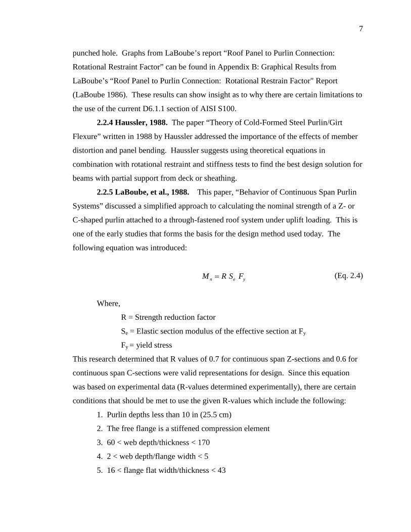
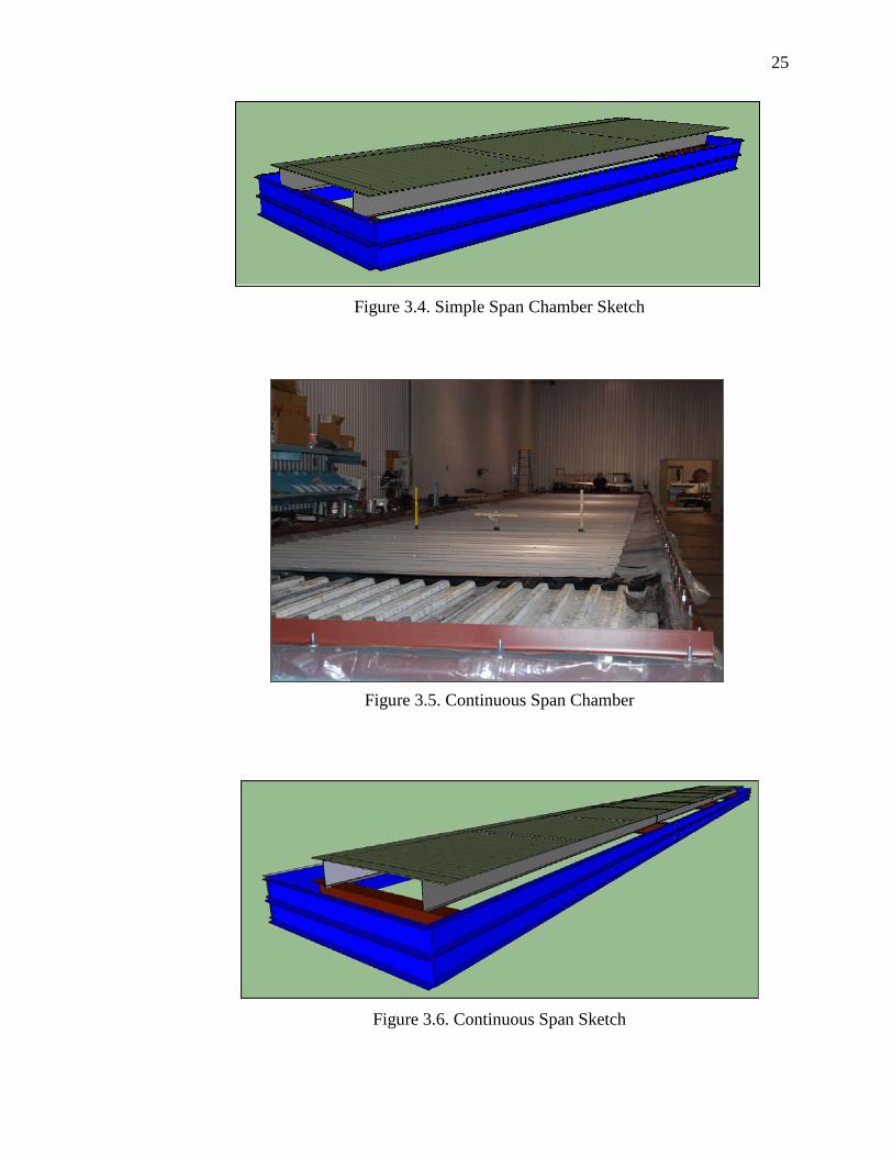
for the simple span and continuous span tests are shown in Figures 3.3, 3.4, 3.5, and 3.6.
Figure 3.3. Simple Span Chamber
25
Figure 3.4. Simple Span Chamber Sketch
Figure 3.5. Continuous Span Chamber
Figure 3.6. Continuous Span Sketch

26
Structural channels were used to form the walls of the chamber (shown in blue in
the sketches) and W 12x40 sections were used for the support beams (shown in grey in
the sketches). The beams that formed the walls of the chamber were secured to the
concrete floor, and the support beams where connected to the chamber with 5/8 inch
A325 structural bolts. Seams and holes were filled with caulking to make the chamber
more air tight. The chamber-to-floor connection and the purlin support beam-to-
chamber connection are shown in Figures 3.7 and 3.8.
Figure 3.7. Chamber-to-Floor Connection
Figure 3.8. Purlin Support Beam to Chamber Connection

27
The purlins were connected by a flange bolted connection to clips that were
connected to the support beams shown in Figure 3.9. The purlins were assembled facing
each other to achieve anti-rolling. For the continuous span test, the laps, which were
measured from centerline of the purlin support beam to the end of the lapped purlin
sections, were 19.5 inches long. A typical lap connection for the continuous span test is
shown in Figure 3.10.
Figure 3.9. Purlin to Support Beam Connection
Figure 3.10. Continuous Span Typical Lap Connection

28
Once the purlins were assembled to the tests chamber, six mil polyethylene plastic
was used to create a more airtight seal to help hold pressure for the test. This plastic was
folded in such a way so that it would not add any lateral support in addition to the support
given by the panels. This ensured that the test specimen did not gain strength from the
plastic which would not be present in systems on actual buildings. Thicker 60 mil EPDM
black plastic lined the edges of the panels to ensure that the metal would not tear the
thinner plastic. One inch by one inch angles were then screwed to the edges of the
panels. See Figures 3.11 and 3.12 for details.
Figure 3.11. Six Mil. Polyethylene Plastic
Figure 3.12. Sixty Mil EDPM Lining and Angle Connections

29
As illustrated by Figure 3.13, measurements were then taken so that tributary
areas could be determined. The tributary widths for the individual purlins were
determined as the average length between the two purlins divided in half (X) plus the
average length of the screw to the edge of the panel on a given side (Y) plus half the
average length of edge of panel to edge of chamber (Z).
Figure 3.13. Determination of Tributary Width
Deflection gauges were set up at midspan of the simple span chamber and at
midspan of the west span of the continuous span chamber as seen in Figure 3.14. An
auto-level was used to read these gauges.
Figure 3.14. Deflection Gauges

30
Compressors were used to apply pressure to the inside of the chamber, which
simulated an uplift wind load. The compressor fans were Cincinnati model # HP-12E26,
and the motor is a Baldor Motor with 40 Horse Power. The motor can spin up to 3525
RPM and has a frequency of 60 HZ. The compressor to chamber hookup can be seen in
Figure 3.15.
Figure 3.15. Compressor Hookup
For the continuous span test, digital manometers were used to check the pressure
readings at various locations in the big chamber. During the testing, when the chamber
was under pressure, the readings were consistent with each other; thus validating that the
entire system was under uniform pressure.
3.4.2. Test Specimens. The purlins used in these tests were manufactured by
NCI Building Systems. The steel’s specified minimum yield strength of 57 ksi and an
ultimate strength specified at 70ksi.
The same type of paneling and the same size purlins were used in both the simple
span and the continuous span tests. The purlins were formed with a depth of 12 inches.
They had equal flanges of approximately 2.25 inches and flange stiffeners approximately
0.9375 inches in length. A typical purlin shape is shown in Figure 3.16. and the actual
measured values are shown in Table 3.1.

31
Figure 3.16. Cross-Sectional Shape
Table 3.1. Test Purlin Dimensions
Purlin H (in) Thickness
(in) B1 (in) B2 (in) L1 (in) L2 (in) θ1 (deg) θ2 (deg) Radius (in) 1 12.0 0.075 2.25 2.3125 1 0.875 50 50 0.1875 2 12.0 0.073 2.25 2.25 0.9375 0.9375 47 47 0.1875 3 12.0 0.073 2.25 2.25 0.9375 0.9375 47 49 0.1875 4 12.0 0.073 2.25 2.3125 0.9375 0.9375 48 49 0.1875 5 12.0 0.074 2.25 2.25 0.9375 0.9375 46 47 0.1875 6 12.0 0.0735 2.25 2.1875 0.875 0.9375 46 47 0.1875
Average 12.0 0.0736 2.25 2.2604 0.9375 0.9271 47.3 48.2 0.1875

32
Pressure Interval
0 1 2 3 4 5 6 7 8 9 10 11 12 13 14 15 16 17 18 19 20
Inches of water
0.00 1.00 2.00 3.00 4.00 4.50 5.00 5.25 5.50 5.75 6.00 6.25 6.50 6.75 7.00 7.25 7.50 7.75 8.00 8.25 8.50
psf 0.0 5.2 10.4 15.6 20.8 23.4 26.0 27.3 28.6 29.9 31.2 32.5 33.8 35.1 36.4 37.7 39.0 40.3 41.6 42.9 44.2
4. TEST PROCEDURE
4.1. INTRODUCTION
Like the test setup, the procedure for these tests followed closely to the procedure
prescribed in AISI S908: Base Test Method for Purlins Supporting Standing Seam Roof
System (AISI 2004).
4.2. CHAMBER LOADING PROCEDURE
The test specimen was loaded with approximately 5 psf of pressure and held for
60 seconds. AISI S908 states that this initial pressure load shall be applied and released
to set a zero pressure reading. Pressures were checked in various locations to ensure that
there was uniform loading. The chamber pressure was then zeroed and the test loading
began. The pressures were measured both by a water manometer and an electronic
differential pressure manometer. Applied loading was measured in inches of water and
then converted to pressure, as summarized by Table 4.1. Each pressure interval indicated
by Table 4.1 was held for 60 seconds before increasing the pressure to the next level.
Table 4.1. Test Pressure Intervals
Load was applied to the test specimen until failure of a purlin occurred. Failure
was a buckling of the cross-section at the location of maximum moment. Once the
purlins buckled, no additional load was applied and the test was stopped.
Horizontal and vertical deflections were measured at every pressure interval. The
deflection measurements were taken at midspan of the simple span test. The continuous
span deflection measurements were taken at midspan of the end span.

33
5. TEST RESULTS
5.1 INTRODUCTION
Upon completion of the load test, the purlins were visually examined. In both
tests, the failure mode was determined to be lateral-torsional buckling. A typical failed
purlin is shown in Figure 5.1.
Figure 5.1. Typical Purlin Failure
After examining the failure, the test specimens were disassembled and coupons
were cut from the failed purlins for material properties.
5.2. MATERIAL TESTING
Three coupon tests were performed according to ASTM A370 to find the tested
yield and ultimate strengths of the failed purlins. A typical stress-strain curve is show in
Figure 5.2.

34
Figure 5.2. Stress-Strain Curve
The average yield strength for the three coupons was 74.7 ksi, and the average ultimate
tensile strength was found to be 92.2 ksi. This gives the Fu/Fy ratio of 1.23. The percent
elongation was also determined to be an average elongation of 10.3%.
5.3. SIMPLE SPAN TEST RESULTS
A graph of the simple span deflection readings is shown in Figure 5.3. The
horizontal deflections were minimal. The vertical deflections of the north and south
purlins were comparable and varied fairly linearly with increased pressure.
Figure 5.3. Simple Span Test Deflections

35
A failure pressure of 44.2 psf was recorded for the simple span test. Subtracting
the panel weight of 0.91 psf yielded a uniform uplift load of 43.29 psf for the whole area
of the chamber. With a tributary width for the failure purlin of 3.29 feet, and a member
weight (subtracted out) of 4.51 plf, the uniform load on the purlin was computed as 137.9
plf. Since the purlin was simple span, the maximum applied moment was found as
follows:
(Eq. 5.1)
Where,
w= is the uniform load applied to the purlin, kip/ft
L= length of the purlin from centerline to centerline of support beams
The maximum applied moment for the simple span test was computed as 10.35
kip feet.
Based on the coupon test results per ASTM A370, the average yield stress of the
tested purlins was found to be 74.7 ksi. The section modulus of the purlin was then
computed to be 2.78 in3. The fully braced moment capacity of the purlins was found as
follows:
(Eq. 5.2)
Where,
Se = effective section modulus at Fy (74.7 ksi) = 2.78 in.3
Fy = yield stress of the material = 74.7 ksi
This fully braced moment capacity of the simple span test purlin was 17.31 kip-feet. The
R-value was determined by dividing the actual tested moment capacity by the calculated
2
8uwLM =
N e yM S F=

36
fully braced moment capacity. The R-value for the 12 in. simple span Zee purlin uplift
test was computed to be 0.60. A summary table of these simple span calculations can be
found in Appendix D: Summary Table of Test Results.
5.4. CONTINUOUS SPAN TEST RESULTS
A graph of the continuous span deflection readings is shown in Figure 5.4.
Similar to the simple span test deflections, the horizontal deflections were minimal. The
vertical deflections of the north and south purlins were comparable and varied fairly
linearly with increased pressure. For the horizontal deflection readings positive
deflections are deflections to the right while negative deflections are deflections to the
left.
Figure 5.4. Continuous Span Test Deflections
The continuous span test reached a pressure of 40.04 psf when both end span
purlins failed almost simultaneously. Subtracting the panel weight yielded 39.13 psf
applied load. The tributary area for the failed purlin was 5.01 feet. Multiplying the 39.13

37
psf by the tributary width and subtracting the purlin weight resulted in a uniform load on
the purlin of 191.5 plf. The span of the failed purlin was 30.01 feet. The maximum
moment of the failed purlin was found by the following:
(Eq. 5.3)
The maximum moment was found to be 13.8 kip-ft.
The fully braced moment capacity of the purlin was the same as in the simple
span purlin test, 17.31 kip-feet. Dividing the applied moment by the moment of a fully
braced purlin gives an R-value of 0.80. A summary of the continuous span test results
are found in Appendix D: Summary Table of Test Results.
20.08uM wL=

38
6. ANALYSIS OF TEST RESULTS
6.1. INTRODUCTION
Since the goal of the tests was to expand the depth limitation of the previous R-
values for members with depths of 11.5 inches, a statistical analysis was performed to
determine how well the new 12 inch deep test data fit into the previous test data.
6.2. SIMPLE SPAN TEST RESULT ANALYSIS
Appendix E: Statistical Analysis shows comparisons between the average R-value
and the standard deviation for the previous test data only and the average R-value and
standard deviation including the 12 inch test data. The average R-value for the previous
simple span tests with purlins of depths ranging from 8.5 inches to 11.5 inches was
0.6333. When adding in this test result for this simple span test with purlins 12 inches
deep, the average improved to 0.632. This shows that the test results for the 12 inch Z-
purlins fit into the range of the previous test data.
6.3. CONTINUOUS SPAN TEST RESULT ANALYSIS
Similarly to the simple span 12 inch Z-purlin test, the statistical analysis (shown
in Appendix E) proves that the continuous span 12 inch deep test result fits within the
range of previous test data for a similar setup. The previous average without this test data
included was 0.6964 while the new average with this test data included is 0.7031.
Summary tables of these comparisons can also be found in Appendix E: Statistical
Analysis.

39
7. CONCLUSIONS AND RECOMMENDATIONS
7.1. CONCLUSIONS
Based on the findings of this test program, 12” deep Z-purlins do meet or exceed
the required strength computed using the current AISI S100 R-values. The R-value for
the 12” deep Z-purlin simple span test, 0.60, surpasses the S100 specified 0.50 R-value
for purlins up to 11.5” deep. Similarly the continuous span test’s R-value of 0.80
surpasses the specified 0.70 for the 11.5” Z-purlins.
7.2. RECOMMENDATIONS
Based on this study it is recommended that, the limitations of Section D6.1.1 be
expanded to include 12” Zee purlins. The tables in Appendix E support this
recommendation. It is recommended that condition (1) state:
(1) Member depth ≤ 11.5 in. for C-sections and ≤ 12 in for Z-sections
When analyzing the Fu/Fy ratios of the steel used in previous R-value tests, it was
found that the lowest Fu/Fy ratio was 1.21. It is suggested that condition (14) of Section
D6.1.1 be changed to state that the steel’s Fu/Fy ratio should not be less than 1.20. The
data for the ultimate and yield stresses for the Fisher tests were used to determine the
lowest previous Fu/Fy ratio used. A table of Fu/Fy ratios for purlins from the Fisher’s
report and from the tests performed at NCI in 2009 are presented in Appendix F: Fu/Fy
Ratio Table. Therefore, it is also recommended that Condition (14) of Section D6.1.1 be
changed to ensure a ductile steel be used rather than limiting the yield stress of the
material. The original intent of this limitation was to ensure a ductile failure. The yield
stress does not need to be limited for the use of this equation. It is suggested that
condition (14) of Section D6.1.1 state the following:
(14) The Fu/Fy ratio of the member ≥ 1.20.

40
With the inclusion of deeper members, it is also recommended that the limitation
of the depth-to-flange width ratio be extended from the current value of 4.5 to a value of
5.5.

41
8. RECOMMENDATIONS FOR FUTURE RESEARCH
Because R-values are empirical, the use of this approach to design girts and
purlins under suction loading comes with several limitations (or conditions as
summarized in Section 2.3.3). As the metal building industry undergoes changes in
member dimensions, sheet metal properties, fabrication procedures or other similar
changes, other desires to extrapolate the current conditions, such as the depth limitation
being expanded to include 12” deep members, may arise. Future research will then be
needed to ensure that these systems do, in fact, meet or exceed current strength
requirements.
More research may also be to clarify Condition (8) which states that both flanges
are to be prevented from moving laterally at the supports. The tests that the current R-
values are based on all had similar purlin to rafter connections; purlins were flange-bolted
to the supporting members. Web-bolts or other connection methods may not provide the
same lateral or rotational restraint as the flange-bolted setup provides. More research
may be needed to determine what exactly will prevent a purlin from moving laterally at
the supports.
Since more and more metal building companies are also using standing seam
panels rather than through-fastened panels, R-values for these standing seam panels could
be researched in the future as well.

42
APPENDIX A
EFFECTS OF RECOGNIZING PARTIAL BRACING PROVIDED BY THROUGH-
FASTENED SHEATHING
43
1.0
30.01 360.12 y x t
y x t
K K KL L L ft in
= = =
= = = =
55
70 y
u
F ksiF ksi
=
=
2
2 2.355 ey
y y
y
E ksiK L
r
πσ = =
29500 1.0243 y
E ksir in==
21.2807 4.5259 11300
o
A inr inG ksi
===
4
6
0.002170 37.475 w
J inC in=
=
2.1823 2b o
e ey tf
C r AF ksiS
σ σ= =
34.1483
1.0f
b
S inC
=
=
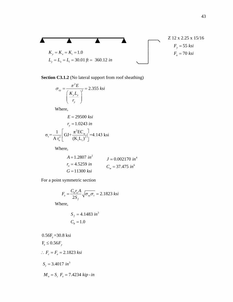
Z 12 x 2.25 x 15/16
Section C3.1.2 (No lateral support from roof sheathing)
Where,
Where,
For a point symmetric section
Where,
2w
t 2 2o t t
π EC1σ = GJ+ =4.143 ksiA r (K L )
y
e
0.56F =30.8 ksi
F 0.56 yF≤
2.1823 c eF F ksi∴ = =
33.4017 cS in=
7.4234 -n c eM S F kip in= =

44
3
0.703.4017 e
RS in=
=
Section D6.1.1 (Recognizing lateral support from roof sheathing)
Where (for continuous spans Z-sections),
Conclusion
For this particular example, recognizing the bracing support from the sheathing
will greatly increase the design capacity of the system. The calculated design strength
without the recognition of the bracing support provided by the paneling is so small for
this setup, a span length of this length likely would not have even been designed if the
S100 did not have provisions that recognized the lateral support from the through
fastened sheathing.
n e yM R S F=
130.97 nM kip in= −
45
APPENDIX B
GRAPHICAL RESULTS FROM LABOUBE’S “ROOF PANEL TO PURLIN
CONNECTION: ROTATIONAL RESTRAINT FACTOR” REPORT (LaBoube 1986)

46
Figure B.1. Affect of Purlin Thickness
Figure B.2. Affect of Purlin Depth

47
Figure B.3. Affect of Panel Depth
Figure B.4. Affect of Panel Thickness

48
Figure B.5. Affect of Insulation Thickness
Figure B.6. Affect of Fastener Type

49
Figure B.7. Affect of Fastener Location

50
APPENDIX C
FULL DETAIL OF PBR PANEL

51

52
APPENDIX D
SUMMARY TABLE OF TEST RESULTS

53
Se 2.78 in3 Se 2.78 in3
Fy 74.7 ksi Fy 74.7 ksiTrib_width 5.01 ft Trib_width 3.29 ft
Span Length 30.01 ft Span Length 24.5 ftGamma_liquid 62.4 pcf Gamma_liquid 62.4 pcfMano. Reading 7.7 in Mano. Reading 8.5 in
Panel Wt. 0.91 psf Panel Wt. 0.91 psfMember Wt 4.51 plf Member Wt 4.51 plf
Uniform Load 39.13 psf Uniform Load 43.29 psfUniform Load 191.53 plf Uniform Load 137.91 plf
Max_Mom. 13.80 kip-ft Max_Mom. 10.35 kip-ft
Mn 17.31 kip-ft Mn 17.31 kip-ft
R Value 0.797 R Value 0.598
Continuous Span
Max Applied Moment
Fully Braced Nom. Mom. Capacity
R Value
Simple Span
Max Applied Moment
Fully Braced Nom. Mom. Capacity
R Value
Table D.1. Summary Table of Test Results
53

54
APPENDIX E
STATISTICAL ANALYSIS

55
R-Value Depth R-ValueLaBoube (1988) 1 0.72 Fisher (1996) 8.5" M1 0.64
2 0.83 M1 0.653 0.72 M1 0.624 0.8 M1 0.625 0.67 M1 0.576 0.64 M1 0.707 0.65 M1 0.748 0.68 M1 0.669 0.7 M1 0.54
10 0.62 M2 0.7211 0.69 M2 0.6712 0.72 M2 0.6813 0.72 M2 0.6314 0.59 M2 0.65
NCI 2009 1 0.797 M2 0.63M2 0.70M2 0.83M2 0.84
Average 0.696 Average 0.703 M2 0.68Stand. Dev 0.065 Stand. Dev 0.067 9.5" 9 0.47
10 0.5427 0.53
M1 0.51M1 0.54
11.5" 11 0.47NCI 2009 12" 1 0.60
Average 0.633 Average 0.632Stand. Dev 0.097 Stand. Dev 0.110
Previous Data New Data Included
Continuous Span
Previous Data New Data Included
Simple Span
Table E.1. Statistical Analysis
55

APPENDIX F
Fu/Fy RATIO TABLE

57
Table F.1. Fu/Fy Ratios
Fu (ksi) Fy (ksi) Fu/Fy
Fisher (1996) 77.7 58.7 1.3278.6 59.0 1.3378.2 59.1 1.3277.8 58.8 1.3281.7 59.6 1.3782.9 61.1 1.3681.7 63.4 1.2978.2 58.0 1.3584.0 62.5 1.3485.0 60.9 1.4076.0 55.9 1.3683.4 61.9 1.3582.8 62.1 1.3380.6 60.9 1.3279.2 59.2 1.3475.6 62.4 1.2181.8 61.0 1.3481.4 62.1 1.3181.9 56.7 1.4480.0 58.0 1.3880.4 48.5 1.6679.8 58.7 1.3680.5 59.6 1.3581.3 58.6 1.3980.6 60.7 1.3376.8 59.5 1.2976.0 49.5 1.5475.7 51.8 1.4675.6 55.9 1.35
NCI (2009) 92.2 74.7 1.23Min: 1.21

58
BIBLIOGRAPHY
Specification for the Design of Cold-Formed Steel Structural Members, 1980 edition, American Iron and Steel Institute, Washington, D.C.
Specification for the Design of Cold-Formed Steel Structural Members, 1986 edition, American Iron and Steel Institute, Washington, D.C
Specification for the Design of Cold-Formed Steel Structural Members, 1996 edition, American Iron and Steel Institute, Washington, D.C.
North American Specification for the Design of Cold-Formed Steel Structural Members, 2001 edition, American Iron and Steel Institute, Washington, D.C.
AISI S100, North American Specification for the Design of Cold-Formed Steel Structural Members, 2007 edition, American Iron and Steel Institute, Washington, D.C
AISI S908-04, Base Test Method for Purlins Supporting Standing Seam Roof Systems, 2004 edition, American Iron and Steel Institute, Washington, D.C.
Eurocode 3 Design of Steel Structures, “General Rules - Supplementary Rules for Cold-Formed Members and Sheeting,” European Committee for Standardization , Brussels 2006.
Fisher, J. M., (1996), “Uplift Capacity of Simple Span Cee and Zee Members with Through – Fastened Roof Panels,” Final Report MBMA 95-01, Metal Building Manufacturers Association, 1996.
Haussler, R. W. and R. F. Pabers (1973), “Connection Strength in Thin Metal Roof Structures,” Proceedings of the Second Specialty Conference on Cold-Formed Steel Structures, University of Missouri-Rolla, Rolla, MO, October 1973.
Haussler, R. W. (1988), “Theory of Cold-Formed Steel Purlin/Girt Flexure,” Proceedings of the Ninth International Specialty Conference on Cold-Formed Steel Structures, University of Missouri-Rolla, MO, November 1988.
LaBoube, R. A. (1986), “Roof Panel to Purlin Connection: Rotational Restraint Factor,” Proceedings of the IABSE Colloquium on Thin-Walled Metal Structures in Buildings, Stockholm, Sweden, 1986.

59
LaBoube, R. A., M. Golovin, D. J. Montague, D. C. Perry, and L. L. Wilson (1988), “Behavior of Continuous Span Purlin System,” Proceedings of the Ninth International Specialty Conference on Cold-Formed Steel Structures, University of Missouri-Rolla, Rolla, MO, November 1988.
Pekoz, T. B. and P. Soroushian (1982), Behavior of C- and Z- Purlins Under Wind Uplift,” Proceedings of the Sixth International Specialty Conference on Cold-Formed Steel Structures, University of Missouri-Rolla, Rolla, MO, November 1982.

60
VITA
Kaye Dee Wibbenmeyer was born on September 16, 1985 in Victoria, Texas. She
earned a Bachelor of Science degree in Civil Engineering in December of 2008 from
Missouri University of Science and Technology. She is currently seeking a Master of
Science degree in Civil Engineering also From Missouri S&T and plans to complete the
requirements for this degree in August 2010. Kaye is also registered as an Engineering
Intern in the State of Missouri.

61