Yamhill River 18-inch and 20-inch HDD Installations Report
106
Revised Geotechnical Engineering and Horizontal Directional Drilling Design Services Yamhill River 18-Inch and 20-Inch HDD Installations Dayton, Oregon for Westech Engineering, Inc. March 26, 2019
-
Upload
khangminh22 -
Category
Documents
-
view
0 -
download
0
Transcript of Yamhill River 18-inch and 20-inch HDD Installations Report
Revised Geotechnical Engineering and Horizontal Directional Drilling Design Services Yamhill River 18-Inch and 20-Inch HDD Installations Dayton, Oregon for Westech Engineering, Inc.
March 26, 2019
Revised Geotechnical Engineering and Horizontal Directional Drilling Design Services
Yamhill River 18-Inch and 20-Inch HDD Installations Dayton, Oregon
for Westech Engineering, Inc.
March 26, 2019
4000 Kruse Way Place Building 3, Suite 200 Lake Oswego, Oregon 503.624.9274

March 26, 2019| Page i File No. 10291-003-00
Table of Contents EXECUTIVE SUMMARY ...................................................................................................................................... ES-1
1.0 INTRODUCTION ............................................................................................................................................... 1
1.1. General ........................................................................................................................................................ 1 1.2. Project Description and Basis of Design ................................................................................................... 1
2.0 SCOPE OF SERVICES ...................................................................................................................................... 2
3.0 SITE CONDITIONS ............................................................................................................................................ 4
3.1. Geological Conditions ................................................................................................................................. 4 3.2. Surface Conditions...................................................................................................................................... 4 3.3. Subsurface Conditions ............................................................................................................................... 5
3.3.1. General ............................................................................................................................................... 5 3.3.2. Subsurface Description ..................................................................................................................... 5 3.3.3. Groundwater Conditions .................................................................................................................... 5
4.0 HORIZONTAL DIRECTIONAL DRILLING (HDD) PROCESS .............................................................................. 6
5.0 HDD DESIGN ELEMENTS ................................................................................................................................ 6
5.1. HDD Geometry ............................................................................................................................................ 6 5.2. Entry/Exit Points and Workspaces ............................................................................................................. 6
6.0 ENGINEERING AND ANALYSIS ....................................................................................................................... 7
6.1. Hydraulic Fracture and Drilling Fluid Surface Release Evaluation .......................................................... 7 6.1.1. General ............................................................................................................................................... 7 6.1.2. Model Input Parameters .................................................................................................................... 7 6.1.3. Results of Hydraulic Fracture and Drilling Fluid Surface Release Analysis .................................... 8
6.2. Pipe Collapse/Rupture Analysis .............................................................................................................. 10 6.3. Pullback Loads ......................................................................................................................................... 11
7.0 HDD CONSTRUCTION CONSIDERATIONS ................................................................................................... 12
7.1. General ..................................................................................................................................................... 12 7.2. Site Access and Workspace Preparation ................................................................................................ 13 7.3. Utilities ...................................................................................................................................................... 13 7.4. Water Sources .......................................................................................................................................... 13 7.5. Noise Mitigation Techniques ................................................................................................................... 13 7.6. Drilling Fluid Containment Pits and Temporary Excavations ................................................................. 14 7.7. Hydraulic Fracture and Drilling Fluid Surface Release .......................................................................... 14 7.8. Pilot Hole Considerations ........................................................................................................................ 15 7.9. Reaming/Swabbing Considerations ....................................................................................................... 15 7.10. Drill Hole Stability and Dry Hole Considerations .................................................................................... 16 7.11. Cuttings Removal and Annular Solids .................................................................................................... 17 7.12. Pullback Considerations .......................................................................................................................... 17
8.0 CONCLUSIONS ............................................................................................................................................. 18
9.0 LIMITATIONS ................................................................................................................................................ 19
10.0 REFERENCES ............................................................................................................................................... 20

March 26, 2019| Page ii File No. 10291-003-00
LIST OF FIGURES
Figure 1. Vicinity Map Figure 2. Site Plan Figure 3. Entry/Pipe Stringing and Fabrication Workspace Photographs Figure 4. Exit Workspace Photographs Figure 5. Estimated Annular Drilling Fluid and Formation Limit Pressures Figure 6. Hydraulic Fracture and Drilling Fluid Surface Release Factors of Safety
APPENDICES
Appendix A. Field Explorations and Laboratory Testing Figure A-1. Key to Exploration Logs Figures A-2 through A-5. Logs of Borings Figures A-6 and A-7. Atterberg Limits Test Results Figures A-8 through A-11. Consolidated Undrained Triaxial Test Results
Appendix B. HDD Design Methodology, Drawings, and Calculations Appendix C. The Horizontal Directional Drilling Process Appendix D. Report Limitations and Guidelines for Use

March 26, 2019 | Page ES-1 File No. 10291-003-00
EXECUTIVE SUMMARY
This revised report provides GeoEngineers, Inc.’s (GeoEngineers) horizontal directional drilling (HDD) design recommendations for the proposed Yamhill River 18-inch-diameter and 20-inch-diameter HDD installations located in Dayton, Oregon. The HDD design drawings included in Appendix B of this report were revised to include the currently proposed pump station and gravity sewer force main associated with the City of Dayton’s (City )Sanitary Sewer System Improvements project. It is our understanding that the proposed HDD installations will replace City water and sanitary lines currently affixed to the existing pedestrian bridge over the Yamhill River at the east end of town. The pedestrian bridge has been closed to pedestrians and is planned for future reconstruction, repair or demolition.
The proposed project consists of installing two new sections of pressurized high-density polyethylene (HDPE) pipe beneath the Yamhill River in parallel alignments with approximately 10 feet of separation. One HDD installation will consist of an 18-inch nominal diameter iron pipe size (IPS) dimension ratio (DR) 7.0 HDPE water pipe (Inside diameter = 12.55-inches), while the other will consist of a 20-inch nominal diameter IPS DR 7.0 HDPE forced sewer main (inside diameter = 13.94 inches). The design horizontal lengths of the proposed HDD installations are each approximately 1,121 feet.
The HDD alignments are generally oriented northeast to southwest (entry to exit) adjacent and parallel to an existing pedestrian bridge. Subsurface conditions at the site generally consist of between approximately 55 and 75 feet of soft to medium stiff silt with occasional sand layers overlying stiff to very stiff low and high plasticity clay soils. The bottom tangents of the HDDs were designed to be located within the very stiff clay soils beneath the Yamhill River. Hydraulic Fracture and drilling fluid surface release analyses indicate that the risk of drilling fluid release to the ground surface during construction is relatively low to moderate.
Based on the information available at this time, it is our opinion that there is a high probability for a qualified HDD contractor to successfully complete these crossings provided the recommendations and considerations in this report are adequately addressed. The HDD contractor should address the items in Sections 7.0 and 8.0 of this report in the preconstruction and construction phases of the project to facilitate a successful HDD installation and attempt to mitigate possible difficulties arising from the HDD installation. Some of the more important considerations from Sections 7.0 and 8.0 of this report are listed below.
■ We recommend the HDD contractor conduct pilot hole and reaming operations from entry (northeast) side of the crossings towards the exit (southwest) sides of the crossings as depicted in the attached HDD design drawings to reduce the risk of hydraulic fracture and drilling fluid surface release.
■ The pipe stringing and fabrication workspace was planned for layout on the entry (northeast) side of the crossings because insufficient area for a continuous pipe stringing and fabrication workspace was present at the exit (southwest) side of the crossings. Therefore, it will likely be necessary for the HDD contractor to move the drill rig from the entry to the exit side of the crossing prior to pullback operations.
■ When preparing the HDD drill plan, the HDD contractor should evaluate the anticipated subsurface soil conditions described in this report, and consider the risk of drilling fluid surface release along the HDD profile and take appropriate measures to reduce the risk of drilling fluid surface release to the extent possible. Such measures may include maintaining appropriate drilling fluid properties and penetration rates for adequate cuttings removal, maintaining drilling fluid returns at all times during construction, monitoring downhole annular pressures during pilot hole operations and cleaning the hole if downhole annular pressure is higher than to be expected, and utilizing a drilling fluid engineer to design, monitor and adjust drilling fluids as necessary during construction.

March 26, 2019 | Page ES-2 File No. 10291-003-00
■ We recommend that the HDD contractor prepare a drilling fluid release contingency plan outlining their plans for identifying, containing and removing drilling fluids in the event there are inadvertent releases of drilling fluid to the Yamhill River or the adjacent ground surface.
The Executive Summary should be used only in context of the full report for which it is intended.
March 26, 2019 | Page 1 File No. 10291-003-00
1.0 INTRODUCTION
1.1. General
This report provides geotechnical engineering and horizontal directional drilling (HDD) design recommendations for the proposed 18-inch and 20-inch Yamhill River HDD installations located in Dayton, Oregon. The location of the project site is shown in the Vicinity Map, Figure 1.
1.2. Project Description and Basis of Design
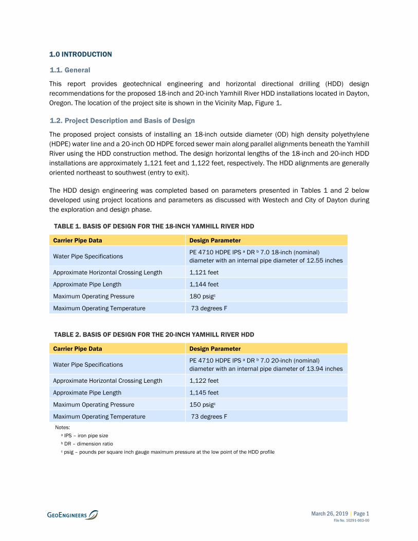
The proposed project consists of installing an 18-inch outside diameter (OD) high density polyethylene (HDPE) water line and a 20-inch OD HDPE forced sewer main along parallel alignments beneath the Yamhill River using the HDD construction method. The design horizontal lengths of the 18-inch and 20-inch HDD installations are approximately 1,121 feet and 1,122 feet, respectively. The HDD alignments are generally oriented northeast to southwest (entry to exit).
The HDD design engineering was completed based on parameters presented in Tables 1 and 2 below developed using project locations and parameters as discussed with Westech and City of Dayton during the exploration and design phase.
TABLE 1. BASIS OF DESIGN FOR THE 18-INCH YAMHILL RIVER HDD
Carrier Pipe Data Design Parameter
Water Pipe Specifications PE 4710 HDPE IPS a DR b 7.0 18-inch (nominal) diameter with an internal pipe diameter of 12.55 inches
Approximate Horizontal Crossing Length 1,121 feet
Approximate Pipe Length 1,144 feet
Maximum Operating Pressure 180 psigc
Maximum Operating Temperature 73 degrees F
TABLE 2. BASIS OF DESIGN FOR THE 20-INCH YAMHILL RIVER HDD
Carrier Pipe Data Design Parameter
Water Pipe Specifications PE 4710 HDPE IPS a DR b 7.0 20-inch (nominal) diameter with an internal pipe diameter of 13.94 inches
Approximate Horizontal Crossing Length 1,122 feet
Approximate Pipe Length 1,145 feet
Maximum Operating Pressure 150 psigc
Maximum Operating Temperature 73 degrees F
Notes: a IPS – iron pipe size b DR – dimension ratio c psig – pounds per square inch gauge maximum pressure at the low point of the HDD profile

March 26, 2019 | Page 2 File No. 10291-003-00
2.0 SCOPE OF SERVICES
The purpose of our services was to characterize subsurface conditions at the site in order to evaluate the feasibility of the proposed 18-inch and 20-inch HDD installations and prepare HDD designs for installation the proposed 18-inch and 20-inch HDPE pipelines. Our specific scope of services included the following:
Task 1. Project Management
1. Prepared field brief documents and a Job Safety Analysis (JSA) for field staff conducting fieldwork operations.
2. Attended project specific conference calls and provided general correspondence.
3. Provided general project management, including invoicing and coordination of staff.
Task 2. Geometric Feasibility
1. Conducted a site visit to evaluate potential entry and exit points and workspaces for the proposed HDD installations. We also marked proposed boring locations during this site visit in preparation of Task 3 design services.
2. Developed a preliminary HDD plan and profile drawing for each HDD. The preliminary plan and profile drawings were used to refine our boring depths and to evaluate geometric feasibility of the HDD.
3. Performed preliminary calculations to verify that a geometrically feasible HDD design will not result in installation or operational stress violations relative to the collapse of the proposed HDPE pipe.
4. Conducted a feasibility analysis in which we evaluated HDPE pipe collapse potential, topographic conditions along the alignment, entry and exit locations, potential workspaces and HDD plan and profile geometry.
5. Attended a conference call meeting to discuss our findings and present conceptual HDD alignments and profiles for further evaluation.
6. Because the HDD installations were found to be geometrically feasible, and the City of Dayton accepted the conceptual HDD plan and profiles, we continued with our Task 3 services below.
Task 3. Subsurface Conditions Evaluation
1. Notified the public “one call” utility locating service to locate utilities near our proposed boring locations.
2. Explored subsurface conditions along the proposed HDD alignments by means of three drilled borings to depths ranging between 31.5 feet and 91.5 feet. While observing the borings we:
a. Obtained soil samples at representative intervals from the borings during standard penetration testing (SPT samples).
b. Obtained one Shelby tube sample in order to collect undisturbed samples of soft silt soils underlying the site.
c. Classified the materials encountered in the borings in general accordance with ASTM International (ASTM) Standard Practices Test Method D 2488.
d. Maintained a detailed log of each boring.

March 26, 2019 | Page 3 File No. 10291-003-00
3. Performed index tests necessary to characterize subsurface conditions for use in crossing design. Testing included:
a. Five Atterberg limits determinations in general accordance with ASTM D4318.
b. Nine percent fines determinations in general accordance with ASTM D1140.
c. One moisture-density relationship.
a. One consolidated undrained triaxial shear strength test on an undisturbed sample of silt soils encountered by the borings.
4. Completed a hydraulic fracture and drilling fluid surface returns analysis (HFA) to evaluate the risk of hydraulic fracture and drilling fluid surface release along the proposed alignments.
5. Discussed our subsurface exploration and HFA findings with you and provided our opinion on the feasibility of the proposed HDD installations from a subsurface conditions standpoint, as well as the risk of hydraulic fracture and drilling fluid surface release.
6. Determined that the HDD installations were feasible from a subsurface conditions standpoint, and confirmed the risk of hydraulic fracture and drilling fluid surface release along the alignment was acceptable to the City of Dayton, and proceeded with our Task 4 services below.
Task 4. HDD Design and Reporting
1. Completed HDD designs in accordance with applicable pipeline design criteria in ASTM design guidelines for HDD installations utilizing HDPE pipe (ASTM F1804-08 and ASTM F1962-05) and the generally accepted practices within the pipeline industry. Our designs include:
a. Alignment and profile of the HDD.
b. Minimum pipeline installation radius.
c. Installation stresses during HDD pullback.
d. Short-term (during pullback) and long-term collapse potential (assuming pressurized and depressurized conditions).a
2. Prepared draft design drawings in AutoCAD format (22” x 34”), for the 18-inch OD water pipeline and the 20-inch OD sewer force main installations. The drawings include:
a. Site-specific topography, including bathymetry within the Yamhill River.
b. Required temporary workspace.
c. Locations of existing underground utilities crossed by the HDD path as documented in the site survey provided to GeoEngineers.
d. Locations of bridge foundations with respect to the proposed HDD alignment and profile.
e. Locations of the borings with respect to the HDD alignment and profile.
3. Provided a draft HDD design report to the project team for review. Our draft report includes:
a. A summary of our site reconnaissance, including a surface description along the proposed alignments.
b. A summary of our field explorations, subsurface materials and laboratory testing.

March 26, 2019 | Page 4 File No. 10291-003-00
c. A summary of our HDD engineering analyses including installation loads, pipe collapse potential and hydraulic fracture and drilling fluid surface release analysis.
d. Proposed entry exit and pipe stringing workspace size and location.
e. Minimum allowable pipe bending radii.
f. Site access, water sources and noise mitigation, as appropriate.
g. HDD conclusions and considerations, including workspace layout, risk of hydraulic fracture and drilling fluid surface release, hole instability and cuttings removal.
h. Geotechnical engineering considerations for temporary roads and workspaces, temporary excavations, construction dewatering and erosion control.
7. Prepare this final HDD design report and HDD design drawings (issued for construction) incorporating review comments.
3.0 SITE CONDITIONS
3.1. Geological Conditions
Geologic mapping we reviewed, (Brownfield and Schlicker 1981; Baldwin and others 1955) indicates that the site is underlain by alluvial deposits of the Quaternary middle terrace of the Willamette River (which are equivalent to the Willamette Silt of Allison 1953). These alluvial deposits are in turn underlain by undivided Oligocene and Eocene aged sedimentary rocks. The Quaternary middle terrace alluvial deposits are described as poorly sorted, unconsolidated to semi-consolidated deposits of clay, silt, sand, and fine to very coarse gravel that are up to approximately 75 feet thick in the project area. Baldwin and others (1955) note that the lower elevations of the Quaternary silt can be difficult to distinguish from underlying weathered sedimentary rocks. The underlying undivided Oligocene and Eocene aged sedimentary rocks are described as light gray to tan sandy tuffaceous siltstone and light brown to gray tuffaceous sandstone.
3.2. Surface Conditions
Our understanding of the site surface conditions is based on a site reconnaissance conducted on September 4, 2018 when we marked boring locations and a review of available aerial photography on Google Earth software.
The proposed Yamhill River HDD installations are generally oriented northeast to southwest (entry to exit) and are offset to the southeast of the existing pedestrian bridge, as shown in the Site Plan, Figure 2. In general, topography along the proposed HDD alignments consists of a relatively flat to gently southeastward sloping plateau that is cut by the Yamhill River. The Yamhill River is incised roughly 30 feet relative to the adjacent plateaus. Slopes within the Yamhill River ravine may be inclined as steep as approximately 100 percent grade. We discussed the entry and exit points with Mr. Muchmore on site as exploration locations were determined with consideration given to existing rights of way and available construction laydown space.
The proposed HDD entry points and entry workspace are situated at an elevation of approximately 105 feet above mean sea level (MSL) (North American Vertical Datum [NAVD] 88) within a relatively flat field vegetated with grasses and volunteer plant species that is adjacent to two wastewater treatment plant ponds. Utilities near the entry points include an underground water pipeline and overhead communication

March 26, 2019 | Page 5 File No. 10291-003-00
and power lines. A southwest-northeast trending cyclone fence crosses the workspace parallel to the proposed HDD alignments. A gate in the fence is located about 200 feet northeast of the proposed entry points. The proposed entry points are offset approximately 10 feet and 20 feet to the southeast of the existing water pipeline and approximately 3 feet and 13 feet of the existing fence, as shown in the HDD design drawings in Appendix B. Photographs of the entry workspace taken during our September 4, 2018 reconnaissance are provided in Figure 3.
The proposed HDD exit points and exit workspace are situated at an elevation of approximately 123 feet MSL within City ROW adjacent to a residential neighborhood where the ground surface gently slopes northeastward toward the Yamhill River. The proposed HDD exit points are positioned within the paved surface of the existing Ferry Street ROW as shown in the HDD design drawings in Figure 2. Site-specific survey data recording the location of known underground and overhead utilities did not extend to the proposed HDD exit points; however, based on our site reconnaissance we anticipate that underground utilities near the proposed exit points may consist of a communications line on the northwest side of Ferry Street and a water pipelines on the southeast side of Ferry Street and a water pipeline crossing Ferry Street near the proposed HDD exit points. Photographs of the proposed exit workspace are provided in Figure 4.
The proposed pipe stringing and fabrication workspace extends approximately 1,170 feet northeast of the proposed entry points along SE Kreder Road and relatively flat land to the east of the road, as shown in Figure 2. The ground surface within the pipe stringing and fabrication workspace consists of the gravel surface of SE Kreder Road, and grass covered area east of the road surface. The southeast end of the pipe stringing and fabrication workspace can be seen in Photograph 2 provided in Figure 3.
3.3. Subsurface Conditions
3.3.1. General
We explored subsurface conditions near the proposed HDD alignment on September 12 and 13, 2018, by advancing three borings to depths of up to 91.5 feet bgs at the locations shown in Figure 2. A boring completed for the City of Dayton Main Sewer Pump Station near the exit side of the HDDs was completed on February 23, 2016. A representative from GeoEngineers, Inc. (GeoEngineers) maintained logs of the materials encountered in each boring and collected soil samples at 2.5- to 5-foot intervals during standard penetration testing. Appendix A, Field Explorations and Laboratory Testing, presents the boring logs and a description of the subsurface exploration and laboratory testing program.
3.3.2. Subsurface Description
In general, subsurface materials encountered in the borings were consistent with geologic mapping we reviewed. The borings typically encountered between 5 and approximately 10 feet of medium stiff silt with gravel or medium stiff clay with gravel fill soils overlying interbedded soft to medium stiff silts and very loose to medium dense sand (Willamette Silt) was intern overlying interbedded stiff to hard clay, medium dense sand and very stiff silt (weathered sedimentary rocks). Refer to the boring logs presented in Appendix A for a detailed description of subsurface materials encountered by our borings.
3.3.3. Groundwater Conditions
Due to the presence of drilling fluid during the explorations, groundwater was not measured at the time of drilling. We anticipate that the static groundwater level in the area is located near the elevation of the Yamhill River. We expect that groundwater levels at the site will fluctuate based on site utilization, precipitation or other factors.
March 26, 2019 | Page 6 File No. 10291-003-00
4.0 HORIZONTAL DIRECTIONAL DRILLING (HDD) PROCESS
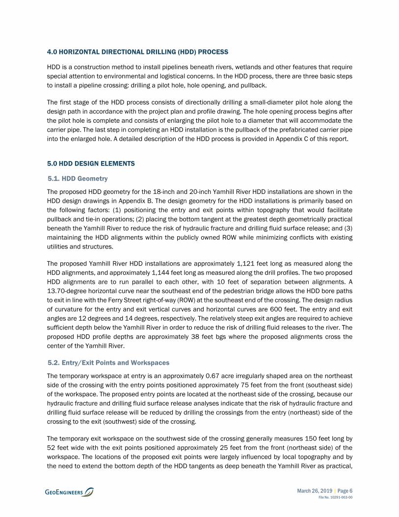
HDD is a construction method to install pipelines beneath rivers, wetlands and other features that require special attention to environmental and logistical concerns. In the HDD process, there are three basic steps to install a pipeline crossing: drilling a pilot hole, hole opening, and pullback.
The first stage of the HDD process consists of directionally drilling a small-diameter pilot hole along the design path in accordance with the project plan and profile drawing. The hole opening process begins after the pilot hole is complete and consists of enlarging the pilot hole to a diameter that will accommodate the carrier pipe. The last step in completing an HDD installation is the pullback of the prefabricated carrier pipe into the enlarged hole. A detailed description of the HDD process is provided in Appendix C of this report.
5.0 HDD DESIGN ELEMENTS
5.1. HDD Geometry
The proposed HDD geometry for the 18-inch and 20-inch Yamhill River HDD installations are shown in the HDD design drawings in Appendix B. The design geometry for the HDD installations is primarily based on the following factors: (1) positioning the entry and exit points within topography that would facilitate pullback and tie-in operations; (2) placing the bottom tangent at the greatest depth geometrically practical beneath the Yamhill River to reduce the risk of hydraulic fracture and drilling fluid surface release; and (3) maintaining the HDD alignments within the publicly owned ROW while minimizing conflicts with existing utilities and structures.
The proposed Yamhill River HDD installations are approximately 1,121 feet long as measured along the HDD alignments, and approximately 1,144 feet long as measured along the drill profiles. The two proposed HDD alignments are to run parallel to each other, with 10 feet of separation between alignments. A 13.70-degree horizontal curve near the southeast end of the pedestrian bridge allows the HDD bore paths to exit in line with the Ferry Street right-of-way (ROW) at the southeast end of the crossing. The design radius of curvature for the entry and exit vertical curves and horizontal curves are 600 feet. The entry and exit angles are 12 degrees and 14 degrees, respectively. The relatively steep exit angles are required to achieve sufficient depth below the Yamhill River in order to reduce the risk of drilling fluid releases to the river. The proposed HDD profile depths are approximately 38 feet bgs where the proposed alignments cross the center of the Yamhill River.
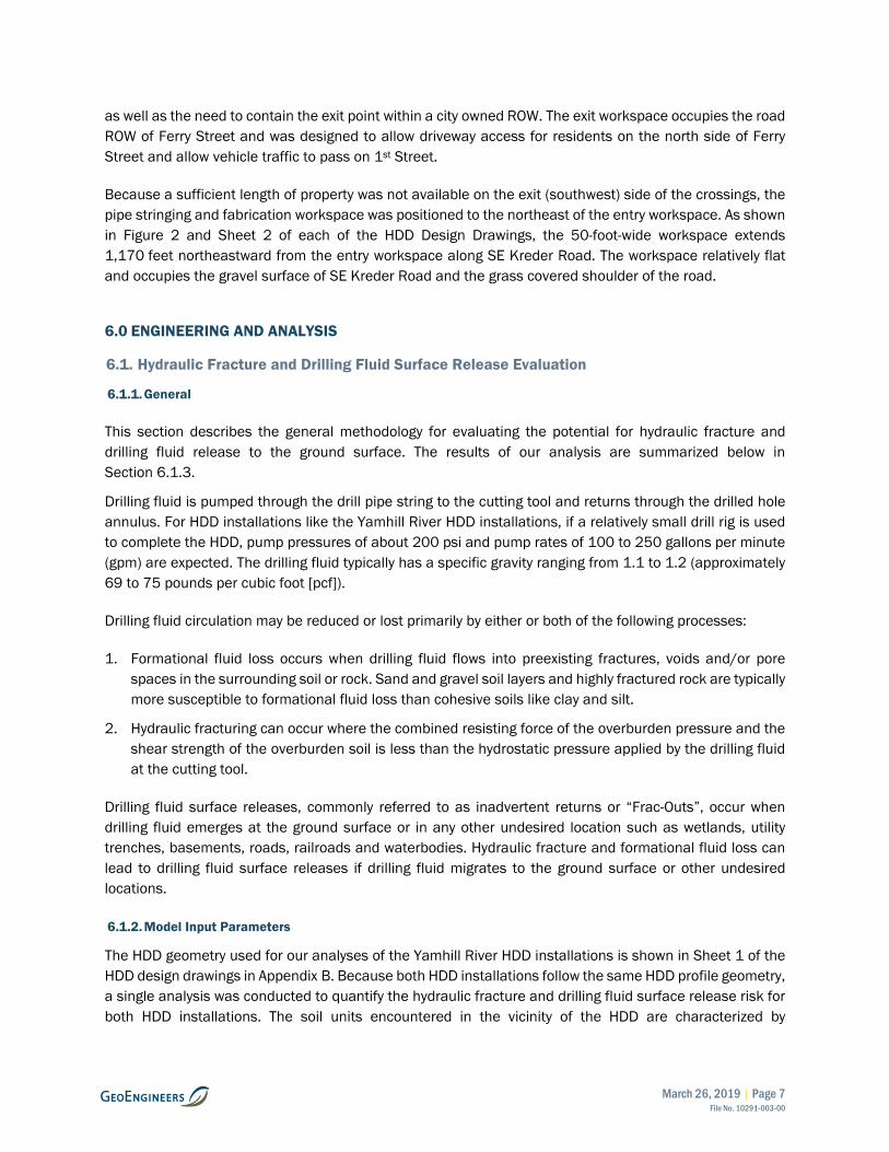
5.2. Entry/Exit Points and Workspaces
The temporary workspace at entry is an approximately 0.67 acre irregularly shaped area on the northeast side of the crossing with the entry points positioned approximately 75 feet from the front (southeast side) of the workspace. The proposed entry points are located at the northeast side of the crossing, because our hydraulic fracture and drilling fluid surface release analyses indicate that the risk of hydraulic fracture and drilling fluid surface release will be reduced by drilling the crossings from the entry (northeast) side of the crossing to the exit (southwest) side of the crossing.
The temporary exit workspace on the southwest side of the crossing generally measures 150 feet long by 52 feet wide with the exit points positioned approximately 25 feet from the front (northeast side) of the workspace. The locations of the proposed exit points were largely influenced by local topography and by the need to extend the bottom depth of the HDD tangents as deep beneath the Yamhill River as practical,
March 26, 2019 | Page 7 File No. 10291-003-00
as well as the need to contain the exit point within a city owned ROW. The exit workspace occupies the road ROW of Ferry Street and was designed to allow driveway access for residents on the north side of Ferry Street and allow vehicle traffic to pass on 1st Street.
Because a sufficient length of property was not available on the exit (southwest) side of the crossings, the pipe stringing and fabrication workspace was positioned to the northeast of the entry workspace. As shown in Figure 2 and Sheet 2 of each of the HDD Design Drawings, the 50-foot-wide workspace extends 1,170 feet northeastward from the entry workspace along SE Kreder Road. The workspace relatively flat and occupies the gravel surface of SE Kreder Road and the grass covered shoulder of the road.
6.0 ENGINEERING AND ANALYSIS
6.1. Hydraulic Fracture and Drilling Fluid Surface Release Evaluation
6.1.1. General
This section describes the general methodology for evaluating the potential for hydraulic fracture and drilling fluid release to the ground surface. The results of our analysis are summarized below in Section 6.1.3.
Drilling fluid is pumped through the drill pipe string to the cutting tool and returns through the drilled hole annulus. For HDD installations like the Yamhill River HDD installations, if a relatively small drill rig is used to complete the HDD, pump pressures of about 200 psi and pump rates of 100 to 250 gallons per minute (gpm) are expected. The drilling fluid typically has a specific gravity ranging from 1.1 to 1.2 (approximately 69 to 75 pounds per cubic foot [pcf]).
Drilling fluid circulation may be reduced or lost primarily by either or both of the following processes:
1. Formational fluid loss occurs when drilling fluid flows into preexisting fractures, voids and/or pore spaces in the surrounding soil or rock. Sand and gravel soil layers and highly fractured rock are typically more susceptible to formational fluid loss than cohesive soils like clay and silt.
2. Hydraulic fracturing can occur where the combined resisting force of the overburden pressure and the shear strength of the overburden soil is less than the hydrostatic pressure applied by the drilling fluid at the cutting tool.
Drilling fluid surface releases, commonly referred to as inadvertent returns or “Frac-Outs”, occur when drilling fluid emerges at the ground surface or in any other undesired location such as wetlands, utility trenches, basements, roads, railroads and waterbodies. Hydraulic fracture and formational fluid loss can lead to drilling fluid surface releases if drilling fluid migrates to the ground surface or other undesired locations.
6.1.2. Model Input Parameters
The HDD geometry used for our analyses of the Yamhill River HDD installations is shown in Sheet 1 of the HDD design drawings in Appendix B. Because both HDD installations follow the same HDD profile geometry, a single analysis was conducted to quantify the hydraulic fracture and drilling fluid surface release risk for both HDD installations. The soil units encountered in the vicinity of the HDD are characterized by
March 26, 2019 | Page 8 File No. 10291-003-00
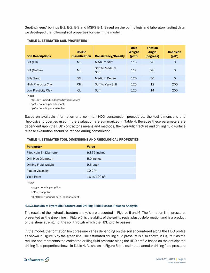
GeoEngineers’ borings B-1, B-2, B-3 and MSPS B-1. Based on the boring logs and laboratory-testing data, we developed the following soil properties for use in the model.
TABLE 3. ESTIMATED SOIL PROPERTIES
Soil Descriptions USCSa
Classification Consistency/Density
Unit Weight (pcfb)
Friction Angle
(degrees) Cohesion
(psfc)
Silt (Fill) ML Medium Stiff 115 26 0
Silt (Native) ML Soft to Medium Stiff 117 28 0
Silty Sand SM Medium Dense 120 30 0
High Plasticity Clay CH Stiff to Very Stiff 125 12 200
Low Plasticity Clay CL Stiff 125 14 200
Notes: a USCS = Unified Soil Classification System b pcf = pounds per cubic foot; c psf = pounds per square foot
Based on available information and common HDD construction procedures, the tool dimensions and rheological properties used in the evaluation are summarized in Table 4. Because these parameters are dependent upon the HDD contractor’s means and methods, the hydraulic fracture and drilling fluid surface release evaluation should be refined during construction.
TABLE 4. ESTIMATED TOOL DIMENSIONS AND RHEOLOGICAL PROPERTIES
Parameter Value
Pilot Hole Bit Diameter 9.875 inches
Drill Pipe Diameter 5.0 inches
Drilling Fluid Weight 9.5 ppga
Plastic Viscosity 10 CPb
Yield Point 16 lb/100 sfc
Notes: a ppg = pounds per gallon b CP = centipoise c lb/100 sf = pounds per 100 square feet
6.1.3. Results of Hydraulic Fracture and Drilling Fluid Surface Release Analysis
The results of the hydraulic fracture analysis are presented in Figures 5 and 6. The formation limit pressure, presented as the green line in Figure 5, is the ability of the soil to resist plastic deformation and is a product of the shear strength of the soil through which the HDD profile passes.
In the model, the formation limit pressure varies depending on the soil encountered along the HDD profile as shown in Figure 5 by the green line. The estimated drilling fluid pressure is also shown in Figure 5 as the red line and represents the estimated drilling fluid pressure along the HDD profile based on the anticipated drilling fluid properties shown in Table 4. As shown in Figure 5, the estimated annular drilling fluid pressure

March 26, 2019 | Page 9 File No. 10291-003-00
drops to zero approximately at station 3+25. This decrease in estimated annular drilling fluid pressure corresponds with the drilling fluid equilibrium point, above which will be “dry hole” (drilling fluid does not continuously occupy the drill hole). Above the drilling fluid equilibrium point, drilling fluid pressure in the hole is generally reduced because of gravity promoting movement of drilling fluid from the drill bit to the drilling fluid equilibrium point.
When evaluating the risk of hydraulic fracture and drilling fluid surface releases, the analysis computes two types of safety factors. These are:
■ Factor of safety against localized hydraulic fracture
■ Factor of safety against drilling fluid surface release
Local Hydraulic Fracture: The factor of safety against hydraulic fracture is the ratio of the formation limit pressure to the estimated drilling fluid pressure along the profile, shown as the green line in Figure 6. This represents the factor of safety against hydraulic fracture of the soil immediately surrounding the HDD profile and is a localized condition.
Drilling Fluid Surface Release: The factors of safety against drilling fluid surface release considers the strength of the soil column above the HDD profile that resists drilling fluid migrating to the ground surface. It is computed by comparing the formation limit pressure of the soil units above a specific point along the planned HDD alignment to the anticipated drilling fluid pressure at the same point. The factors of safety against drilling fluid surface releases are shown in Figure 6 at selected points shown as red triangles.
Table 5 below shows the relative risk associated with the estimated factors of safety against hydraulic fracture and drilling fluid surface releases.
TABLE 5. RELATIVE HYDRAULIC FRACTURE AND DRILLING FLUID SURFACE RELEASE RISK
Factor of Safety Relative Risk
Less than 1 Very High
Between 1 and 1.5 High
Between 1.5 and 2 Moderate
Greater than 2 Low
As shown in Figure 6, the model indicates that the risk of localized hydraulic fracture is generally low except beneath the Yamhill River between approximate stations 8+10 and 7+05 (approximately 550 feet to 655 feet southwest of the HDD entry point) where the risk is moderate with calculated safety factors ranging from about 1.8 to 1.9. This decrease in factor of safety is primarily the result of the proposed HDD profiles passing through a layer of relatively low strength clay and the reduced depth of cover beneath the river. Factors of safety against drilling fluid release were not computed to the southwest of station 3+25 (the drilling fluid equilibrium point) because southwest of the drilling fluid equilibrium point drilling fluid pressure in the hole drops to zero under normal drilling conditions with drilling fluid circulation back to the entry point.
March 26, 2019 | Page 10 File No. 10291-003-00
Although not specifically shown by our model, the risk of hydraulic fracture and drilling fluid surface release within approximately 50 to 100 feet of the HDD entry and exit points is considered to be high as is typical with HDD installations because of the decrease in soil cover and overburden pressure.
6.2. Pipe Collapse/Rupture Analysis
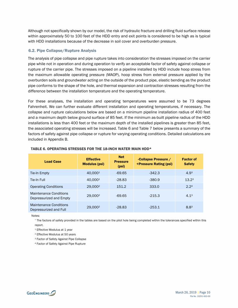
The analysis of pipe collapse and pipe rupture takes into consideration the stresses imposed on the carrier pipe while not in operation and during operation to verify an acceptable factor of safety against collapse or rupture of the carrier pipe. The stresses imposed on a pipeline installed by HDD include hoop stress from the maximum allowable operating pressure (MAOP), hoop stress from external pressure applied by the overburden soils and groundwater acting on the outside of the product pipe, elastic bending as the product pipe conforms to the shape of the hole, and thermal expansion and contraction stresses resulting from the difference between the installation temperature and the operating temperature.
For these analyses, the installation and operating temperatures were assumed to be 73 degrees Fahrenheit. We can further evaluate different installation and operating temperatures, if necessary. The collapse and rupture calculations below are based on a minimum pipeline installation radius of 400 feet and a maximum depth below ground surface of 85 feet. If the minimum as-built pipeline radius of the HDD installations is less than 400 feet or the maximum depth of the installed pipelines is greater than 85 feet, the associated operating stresses will be increased. Table 6 and Table 7 below presents a summary of the factors of safety against pipe collapse or rupture for varying operating conditions. Detailed calculations are included in Appendix B.
TABLE 6. OPERATING STRESSES FOR THE 18-INCH WATER MAIN HDD*
Load Case Effective
Modulus (psi)
Net Pressure
(psi)
-Collapse Pressure / +Pressure Rating (psi)
Factor of Safety
Tie-In Empty 40,0001 -69.65 -342.3 4.93
Tie-In Full 40,0001 -28.83 -380.9 13.23
Operating Conditions 29,0002 151.2 333.0 2.24
Maintenance Conditions Depressurized and Empty 29,0002 -69.65 -215.3 4.13
Maintenance Conditions Depressurized and Full 29,0002 -28.83 -253.1 8.83
Notes: * The factors of safety provided in the tables are based on the pilot hole being completed within the tolerances specified within this report. 1 Effective Modulus at 1 year 2 Effective Modulus at 50 years 3 Factor of Safety Against Pipe Collapse 4 Factor of Safety Against Pipe Rupture

March 26, 2019 | Page 11 File No. 10291-003-00
TABLE 7. OPERATING STRESSES FOR THE 20-INCH FORCED SEWER MAIN HDD*
Load Case Effective Modulus
(psi)
Net Pressure (psi)
-Collapse Pressure / +Pressure
Rating (psi)
Factor of Safety
Tie-In Empty 40,0001 -69.65 -342.3 4.93
Tie-In Full 40,0001 -28.36 -382.5 13.53
Operating Conditions 29,0002 121.6 333.0 2.74
Maintenance Conditions Depressurized and Empty 29,0002 -69.65 -215.3 3.13
Maintenance Conditions Depressurized and Full 29,0002 -28.36 -254.6 9.03
Notes: * The factors of safety provided in the tables are based on the pilot hole being completed within the tolerances specified within this report. 1 Effective Modulus at 1 year 2 Effective Modulus at 50 years 3 Factor of Safety Against Pipe Collapse 4 Factor of Safety Against Pipe Rupture
6.3. Pullback Loads
The analyses of installation loads are based on the product pipe being installed along the designed path using the BMPs of the HDD industry. The addition of water into the product pipe is the standard method that contractors typically use to control buoyancy of the product pipe during the installation procedure. The proposed 18-inch-diameter and 20-inch-diameter HDPE pipes will be positively buoyant in the anticipated drilling fluid weights. Because of high buoyant forces and net external pressures on the product pipe without the use of buoyancy control, the HDD contractor must fill the product pipe pull section with water to reduce the buoyant and pull forces and to reduce the risk of overstressing the product pipe during pullback operations. To accomplish this, the contractor typically inserts a smaller diameter HDPE pipe (2- to 4-inch-diameter) into the carrier pipe which is supported by pipe rollers and fills the carrier pipe (from the pullhead back towards the end of the carrier pipe string) with water as it is being pulled into the reamed hole such that the water level in the pipe achieves neutral buoyancy during the entire pullback process. Our analyses include a range of cases with differing weights of drilling fluid in the hole. The three cases analyzed are as follows:
1. The annulus contains 9.5 lb/gal drilling fluid and the product pipe full of water.
2. The annulus contains 10.5 lb/gal drilling fluid and the product pipe full of water.
3. The annulus contains 12 lb/gal drilling fluid and the product pipe is full of water.
The pullback force analyses are based upon the methods developed by the Pipeline Research Committee International (PRCI) of the American Gas Association (PRCI, 1995).
The pullback stress analyses are based on procedures described in ASTM F1962-05. We utilized a tensile yield stress of 3,200 psi (PE 4710) and a design factor of 0.4 to calculate safe pull force. The safe pull forces were then reduced to account for combined tensile, bending and hoop stresses.
March 26, 2019 | Page 12 File No. 10291-003-00
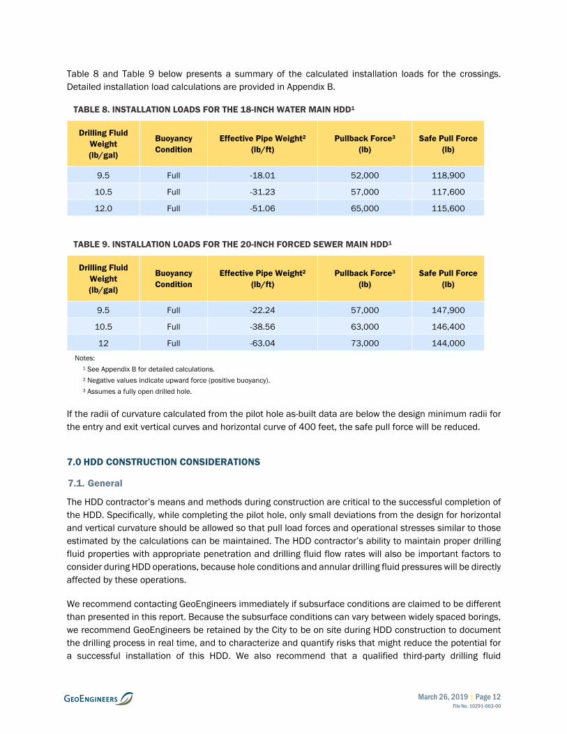
Table 8 and Table 9 below presents a summary of the calculated installation loads for the crossings. Detailed installation load calculations are provided in Appendix B.
TABLE 8. INSTALLATION LOADS FOR THE 18-INCH WATER MAIN HDD1
Drilling Fluid Weight (lb/gal)
Buoyancy Condition
Effective Pipe Weight2 (lb/ft)
Pullback Force3 (lb)
Safe Pull Force (lb)
9.5 Full -18.01 52,000 118,900
10.5 Full -31.23 57,000 117,600
12.0 Full -51.06 65,000 115,600
TABLE 9. INSTALLATION LOADS FOR THE 20-INCH FORCED SEWER MAIN HDD1
Drilling Fluid Weight (lb/gal)
Buoyancy Condition
Effective Pipe Weight2 (lb/ft)
Pullback Force3 (lb)
Safe Pull Force (lb)
9.5 Full -22.24 57,000 147,900
10.5 Full -38.56 63,000 146,400
12 Full -63.04 73,000 144,000
Notes: 1 See Appendix B for detailed calculations. 2 Negative values indicate upward force (positive buoyancy). 3 Assumes a fully open drilled hole.
If the radii of curvature calculated from the pilot hole as-built data are below the design minimum radii for the entry and exit vertical curves and horizontal curve of 400 feet, the safe pull force will be reduced.
7.0 HDD CONSTRUCTION CONSIDERATIONS
7.1. General
The HDD contractor’s means and methods during construction are critical to the successful completion of the HDD. Specifically, while completing the pilot hole, only small deviations from the design for horizontal and vertical curvature should be allowed so that pull load forces and operational stresses similar to those estimated by the calculations can be maintained. The HDD contractor’s ability to maintain proper drilling fluid properties with appropriate penetration and drilling fluid flow rates will also be important factors to consider during HDD operations, because hole conditions and annular drilling fluid pressures will be directly affected by these operations.
We recommend contacting GeoEngineers immediately if subsurface conditions are claimed to be different than presented in this report. Because the subsurface conditions can vary between widely spaced borings, we recommend GeoEngineers be retained by the City to be on site during HDD construction to document the drilling process in real time, and to characterize and quantify risks that might reduce the potential for a successful installation of this HDD. We also recommend that a qualified third-party drilling fluid

March 26, 2019 | Page 13 File No. 10291-003-00
engineer/technician be required to be part of the HDD contractor’s team to evaluate the drilling fluid properties on a continuous basis throughout the entire HDD process. Close coordination between the HDD contractor and the drilling fluid engineer/technician is vital to maintaining proper drilling fluid properties, penetration rates and drilling fluid flow rates.
7.2. Site Access and Workspace Preparation
The proposed HDD entry and pipe stringing and fabrication workspaces can be accessed from SE Kreder Road. We do not anticipate that temporary site improvements (i.e. gravel surfacing or construction mats) within most of the entry workspace will be required. However, if construction is completed at times of heavy or prolonged precipitation, the portion of the workspace south of SE Kreder Road may require temporary stabilization such as gravel surfacing or construction timber mats. These temporary improvements should be removed upon completion of the pipe installations, and the areas should be restored in accordance with the project site restoration plan. We do not anticipate that grading or significant vegetation removal will be required to prepare the entry workspace and pipe stringing workspace for HDD operations.
The exit workspace is positioned within Ferry Street. As such, we do not anticipate that grading will be required to prepare the exit workspace for HDD operations. However, the HDD contractor should present plans to secure exit pit excavations required for HDD operations as part of their drill plan.
A traffic control plan and site access coordination should be developed for the site, particularly the exit workspace, because it is within a residential neighborhood. We recommend coordinating the traffic control plan with the HDD contractor because their means and methods will directly affect the required traffic control throughout all phases of HDD construction.
7.3. Utilities
We recommend that the HDD contractor physically locate (pothole) all utilities that are within the entry and exit workspaces, or crossed by the proposed HDD alignment, prior to initiating pilot hole operations to verify the location and depth of each utility and confirm that HDD operations will not conflict with the utilities.
7.4. Water Sources
A reliable source of water for drilling operations is required during the HDD installation process. In addition, water is also required for the hydrostatic testing of the carrier pipe. We understand that there is a fire hydrant near the proposed entry point where water can be obtained during construction.
7.5. Noise Mitigation Techniques
Because the proposed temporary entry and exit workspaces for the HDD are located in the vicinity of existing residences, noise mitigation measures may be required during HDD operations. If required, diesel power units associated with heavy equipment may be outfitted with noise-reducing mufflers. In addition, the workspace can be muffled by placing baffles around the equipment to further reduce noise emissions. The actual placement of the noise reduction measures should be implemented by the selected HDD contractor.
March 26, 2019 | Page 14 File No. 10291-003-00
7.6. Drilling Fluid Containment Pits and Temporary Excavations
Drilling fluid containment pits will be required at the HDD entry and exit workspaces. Depending on the HDD contractor’s drilling fluid pit excavation practices, drilling fluid containment pit excavations are typically constructed adjacent to the centerline near the entry and exit point locations. Drilling fluid containment pits can vary in size but are usually not larger than 10 feet long by 8 feet wide and 6 feet deep.
Based on the borings completed at the site, soils within the planned excavation depths are anticipated to consist of medium stiff to stiff silt with occasional gravel. Conventional equipment, such as backhoes or excavators, should be suitable for excavation of these soils.
Maintenance of safe working conditions, including temporary excavation stability, is the responsibility of the HDD contractor. All temporary cuts in excess of 4 feet in height should be shored or sloped in accordance with Occupational Safety and Health Administration (OSHA) regulation 1926 Subpart P, Appendix B—Sloping and Benching. For planning purposes, soils encountered within the exploratory borings in the vicinity of the excavation areas should be classified as Type C soil. Temporary excavations in Type C soil should be inclined no steeper than 1.5H:1V. These allowable cut slope inclinations are applicable to excavations above the groundwater table only. Steeper temporary slope inclinations may be allowed if soil conditions are determined to be suitable by the field geotechnical engineer. For open cuts, we recommend that:
■ No traffic, construction equipment, stockpiles or supplies should be allowed within a distance of at least 5 feet from the top of the cut.
■ Construction activities should be scheduled to reduce the length of time the cuts are left open.
■ Erosion control measures should be implemented as appropriate to limit runoff from the site.
■ Surface water should be diverted away from the excavations.
7.7. Hydraulic Fracture and Drilling Fluid Surface Release
The HDD profiles are planned to maintain their path beneath the Yamhill River through stiff to very stiff high plasticity clay soil. The results of the hydraulic fracture and inadvertent drilling fluid returns evaluation indicate that there is a moderate potential hydraulic fracture and drilling fluid surface release as the HDD profiles are advanced southwestward beneath the Yamhill River.
The HDD contractor’s means and methods will greatly affect the risk of hydraulic fracture and drilling fluid surface release. If the HDD contractor operates with inadequate pump volumes, less than ideal drilling fluid properties or excessive rates of penetration, the annulus may become blocked through an accumulation of drill cuttings falling out of suspension and the risk of hydraulic fracture and drilling fluid surface release will be increased. We recommend that the HDD contractor employ the use of a qualified third-party drilling fluid engineer/technician to develop a drilling fluid program and assist with maintaining appropriate drilling fluid properties during HDD operations.
As is typical with all HDD installations, we anticipate that there is a relatively high risk of hydraulic fracture and drilling fluid surface release within about 100 feet of the proposed entry and exit points where there is reduced soil cover.

March 26, 2019 | Page 15 File No. 10291-003-00
7.8. Pilot Hole Considerations
The HDD design drawings in Appendix B include the necessary geometric information required to complete the pilot hole.
We recommend that a secondary survey system (TruTracker, ParaTrack or equivalent) be used along the entire length of the HDD. We recommend that the wire grids be placed at least as wide as the survey probe is deep plus 20 feet. As a result, the depth of the HDD profile will require the coil separation to increase from approximately 20 feet wide near the entry and exit locations to a minimum of approximately 100 feet wide through the deepest portions of the drill profile. The placement of the coils is limited to areas where ground surface conditions, permit requirements and landowner permissions allow.
Based on the design geometry and proposed pipe specifications for the 18-inch and 20-inch HDD installations, the minimum allowable three-joint radius over any consecutive three-joint section should not be less than 400 feet. We recommend that the three-joint radius be calculated for each three-joint section (for Range 2 Drill Pipe, approximately 90 feet) completed during pilot hole operations. The design radii of the entry and exit vertical curves and the horizontal curves of the HDD profiles are 600 feet.
The HDD contractor should complete the pilot hole as closely as possible to the designed HDD alignment and profile while still maintaining three-joint vertical and horizontal radii equal to or greater than the minimum allowable radius of 400 feet. Because of regulations requiring that water and sewer pipes be separated by a minimum distance of 5 feet, we recommend a horizontal tolerance for the 18-inch HDD installation of 2 feet left and 5 feet right of the designed alignment. We recommend a horizontal tolerance for the 20-inch HDD installation of 2 feet right and 5 feet left of the HDD design alignment. We recommend a vertical tolerance of 2 feet above and 10 feet below the designed profile. We also recommend that, upon completion of the pilot hole, GeoEngineers have the opportunity to review the pilot hole survey data prior to the start of reaming operations.
Based on our experience with similar HDD projects of this length and diameter, we anticipate that the pilot bit diameter will likely range from 6.5 to 9.875 inches. We also anticipate that the pilot hole will be advanced using a jetting assembly (Photograph C-1, Appendix C).
The HDD contractor should be responsible for producing and submitting an as-built drawing of the pilot hole survey data within 2 weeks of the completion of the pilot hole. The HDD contractor’s as-built drawing should be reviewed by GeoEngineers prior to storing the data in the project file.
Because of the elevation difference between the entry and exit points, we recommend drilling the pilot hole from the entry side (northeast side) of the HDD alignment to the exit side (southwest side) of the HDD alignment. Drilling from the low side of the crossing to the high side of the crossing will promote drilling fluid returns to the entry point and reduce the hydraulic pressure in the bore hole beneath the Yamhill River, which in turn reduces the risk of drilling fluid surface release to the river.
7.9. Reaming/Swabbing Considerations
During reaming operations, we anticipate that the HDD contractor will likely ream the holes by conducting at least two ream passes per crossing to enlarge the hole to a minimum final hole diameter of approximately 28 inches for the 18-inch HDD crossing and 30 inches for the 20-inch HDD crossing. Because of the elevation difference between the entry and exit points, we recommend conducting reaming operations from

March 26, 2019 | Page 16 File No. 10291-003-00
the entry (northeast) side of the HDD alignment to the exit (southwest) side of the HDD crossing. Like the discussion in the “Pilot Hole Considerations” section above, conducting reaming passes in this manner will promote drilling fluid returns to the entry point, reduce the risk of drilling fluid surface release to the Yamhill River and eliminate the need to transport used drilling fluid from the exit workspace to the entry workspace for processing.
The contactor may elect to conduct forward reaming passes to enlarge the pilot hole which means they will keep the drill rig on the entry side of the crossing and advance the reamer southwest (away from the drill rig) towards the exit side of the crossing. If the contractor elects to conduct forward reaming passes, we recommend utilizing a large excavator or bull dozer positioned on the exit side of the HDD alignment to apply most of the pull force required to advance the reamer toward the exit point. Additionally, we recommend that the HDD contractor maintain a continuous string of drill pipe in the hole at all times during reaming and swabbing operations. Maintaining a drill pipe string in the hole at all times will reduce the risk of the reamer not following the pilot hole and could eliminate the need to conduct operations to recover lost tooling in the event that the drill pipe string breaks and the reamer is lost downhole.
During the reaming operations, the rate of penetration and drilling fluid flow rates should be evaluated to reduce potential problems with inadequate removal of cuttings, hydraulic fracturing and drilling fluid surface releases. Generally accepted Best Management Practices (BMPs) within the HDD industry recommend an annular solids percentage of 30 percent or less, which requires pumping drilling fluid at a flow rate such that the volume of drilling fluid is more than three times the volume of soil cuttings being generated. The annular solids percentage can be adjusted by varying either penetration or pumping rates. If cuttings begin to build up in the hole because of high annular solids content, high drill string torque, stuck tooling or hydraulic fracture and drilling fluid surface release could occur. Refer to Section 7.11 for additional recommendations regarding cuttings removal.
When the reaming process is completed, and prior to pullback operations, we recommend conducting at least one swab pass to clean cuttings from the reamed hole and verify that the reamed hole is ready to receive the carrier pipe.
7.10. Drill Hole Stability and Dry Hole Considerations
In general, it is our opinion that the silty and clayey soils encountered in our explorations are not likely to be prone to significant hole instability. However, there is a difference in elevation between the entry (low side) and exit point (high side) of approximately 19 vertical feet, which will cause the drilling fluid within the hole to drain to the point of equilibrium. The drilling fluid equilibrium point is the point along the profile that is equal to the elevation at the entry point. In this case, the drilling fluid equilibrium point is located approximately 75 feet from the exit point. The remaining 75 feet of the HDD profile located above the point of equilibrium is commonly referred to as “dry hole” and will not have the benefit of being filled with or supported by drilling fluid. It is our opinion that there is a low risk of hole collapse along the portion of the dry hole segment located within the medium stiff to stiff silt observed by boring MSPS-B-1. If hole instability does become a problem during HDD operations, it is technically feasible to excavate a significant length of the “dry hole” segment.

March 26, 2019 | Page 17 File No. 10291-003-00
Proper management of drilling fluid properties throughout the HDD installation process should help maintain the stability of the drilled hole. Care should be taken to remove the cuttings from the drilled hole to prevent an accumulation that might constrict or block the drilled hole, see Section 7.11 below for additional recommendations.
7.11. Cuttings Removal and Annular Solids
Based on our experience, cuttings removal in clays such as those observed by our borings is typically more challenging than in other non-cohesive soils. In some cases, relatively dry clays or high plasticity silts may swell and block the drill hole. In addition, the clay cuttings may “ball up” forming large diameter particles that fall out of suspension and are more difficult to remove than smaller clay particles that remain in suspension. Therefore, the potential for the hole to become plugged with cuttings is elevated along each of the proposed HDD crossings where the drill path is within clay or high plasticity silt. In the event that the hole becomes plugged, and drilling fluid circulation ceases, downhole annular pressures can increase dramatically. This temporary spike in downhole annular pressure can dramatically increase the risk of hydraulic fracture and inadvertent returns of drilling fluid.
If cuttings are not effectively removed from the hole during HDD operations, pullback forces could be excessively high during pullback of the 18-inch-diameter and/or 20-inch-diameter pipes, the pipes could become lodged in the hole, or the pipes could become damaged. The failure to effectively remove cuttings from the hole could potentially result in failure of the HDD installations.
We recommend that the HDD contractor maintain drilling fluid returns at all times and use appropriate means and methods (appropriate penetration rates, drilling fluid management, mechanical methods) to adequately remove the cuttings from the hole during the HDD process.
7.12. Pullback Considerations
Based on our analysis of the installation loads (see Section 6.3), the pullback force during installation of the 18-inch-diameter and 20-inch diameter pipes may be as high as approximately 65,000 pounds and 73,00 pounds, respectively. This anticipated pull force assumes that cuttings are removed from the hole prior to attempting pullback. Improper conditioning of the hole prior to pullback could result in higher installation forces.
The estimated installation forces provided in Tables 8 and 9 suggest that the weight of the drilling fluid in the hole during pullback operations will largely affect the estimated installation forces and calculated safe pull forces. In addition, inadequate preparation of the hole prior to pullback operations, inadequate ballasting of the product pipe or delays during pullback operations may cause pullback forces to exceed those estimated in the calculations.
Because of the likelihood that the HDD contractor may mobilize a maxi-HDD drill rig to complete the installations, the drill rig will likely have a pullback capacity capable of causing damage to the HPDE product pipe during installation. We recommend that the HDD contractor closely monitor the weight of the drilling fluid being pumped downhole and the weight of the drilling fluid returns during the swab pass and that the HDD contractor perform a sufficient number of swab passes to reduce the downhole drilling fluid weight as much as practical. In addition, the contractor should closely monitor pullback forces during installation of the carrier pipes to ensure that the safe pull force is not exceeded. Higher safe pull forces may be allowed if the pipe manufacturer permits a higher design factor to calculate allowable tensile loads.

March 26, 2019 | Page 18 File No. 10291-003-00
We recommend that the HDD contractor utilize a drill rig with a capacity of at least 1.5 times the anticipated pull loads. The HDD contractor should install a deadman anchor of sufficient capacity to withstand the anticipated pull loads; these aspects are generally left to the HDD contractor’s discretion as approved by the owner. We also recommend that during pullback, the 18-inch and 20-inch pipe over-bend radii be maintained at 200 feet or greater to reduce the risk of damaging the carrier pipe during installation.
8.0 CONCLUSIONS
Based on the information available at this time, the results of the exploration and laboratory-testing programs, and our HDD constructability review, it is our opinion that the proposed Yamhill River HDD installations are technically feasible if proper construction techniques as described herein are used. It is our opinion that there is a high probability for a qualified, prepared HDD contractor to successfully complete this crossing provided that the recommendations and considerations in this report are adequately addressed.
The HDD contractor should address the items below in the preconstruction and construction phases of the project to facilitate a successful installation of the HDD and attempt to mitigate possible difficulties that could arise during the HDD installation.
■ Because drilling the Yamhill River HDD crossings from the exit (southwest) side to entry (northeast) side will result in relatively higher annular pressures during pilot hole and reaming operations, we recommend that the contractor conduct pilot hole and reaming operations from northeast to southwest, as depicted in the attached HDD design drawings. Drilling the crossing from entry to exit, as depicted in the design drawings, will reduce the risk of hydraulic fracture and drilling fluid surface release to the Yamhill River.
■ Because insufficient area for a continuous pipe stringing and fabrication workspace was present at the southwest end of the crossings, as well as increased risk of hydraulic fracture and drilling fluid surface release imposed by drilling the crossings from southwest to northeast, it will be necessary for the HDD contractor to move the drill rig from the entry (northeast) side of the crossing to the exit (southwest) side of the crossing to conduct pullback operations.
■ When preparing the HDD drill plan, the HDD contractor should evaluate the anticipated subsurface soil conditions described in this report, consider the risk for drilling fluid surface release beneath the Yamhill River and within 100 feet of the HDD entry and exit points, and take appropriate measures to reduce the risk of drilling fluid surface release to the extent possible. Such measures may include maintaining appropriate drilling fluid properties and penetration rates for adequate cuttings removal, maintaining drilling fluid returns at all times during construction, monitoring downhole annular pressures during pilot hole operations and cleaning the hole if downhole annular pressure is higher than to be expected. We recommend the use of a downhole annular pressure tool during pilot hole operations.
■ We recommend that the HDD contractor prepare a drilling fluid release contingency plan outlining their plans for identifying, containing and removing drilling fluids in the event there are drilling fluid surface releases to the ground surface or Yamhill River.

March 26, 2019 | Page 19 File No. 10291-003-00
■ Maintaining appropriate drilling fluid properties during HDD operations will be vital for effective cuttings removal, reducing the risk of hydraulic fracture, and maintaining drill hole stability during all aspects of HDD operations. We recommend that the HDD contractor employ the use of a qualified third-party drilling fluid engineer/technician to develop a drilling fluid program and assist with maintaining appropriate drilling fluid properties during HDD operations.
■ Ensuring that drilling fluid returns are maintained to the drilling fluid returns pit(s) during HDD operations will assist in removing cuttings from downhole, lubricate the drill pipe string downhole and reduce the risk of hydraulic fracture. The HDD contractor should make reasonable attempts to maintain drilling fluid returns during drilling operations to reduce the risk of complications and increase likelihood for a successful HDD installation.
■ The elevation difference of 19 feet between entry and exit points results in a “dry hole” section along the last approximately 75 feet of the HDD profile. The risk of hole instability and void formation is typically elevated along a dry hole section because it does not have the benefit of being filled with drilling fluid. However, nearly the entire dry hole section is expected to be within medium stiff to stiff silt soil, where we expect the risk of hole instability to be relatively low.
■ The HDD contractor should expose and confirm the depth and location of all utilities along the proposed alignments, and within the entry and exit workspaces prior to initiating the pilot hole, in order to verify that the pilot hole bottom hole assembly and subsequent reaming and pullback operations do not conflict with the existing utilities.
9.0 LIMITATIONS
We have prepared this report for use by Westech Engineering, Inc., City of Dayton, their authorized agents and other approved members of the design team involved with this project. The report is not intended for use by others and the information contained herein is not applicable to other sites. Our report, conclusions and interpretations should not be construed as a warranty of the subsurface conditions. The conclusions and recommendations in this report should be applied in their entirety.
Variations in subsurface conditions are possible between the borings. Subsurface conditions may also vary with time. A contingency for unanticipated conditions should be included in the project budget and schedule for such an occurrence. We recommend that sufficient monitoring and consultation be provided by GeoEngineers during construction to confirm that the conditions encountered are consistent with those indicated by the borings, to provide recommendations for design changes should the conditions revealed during the work differ from those anticipated, and to evaluate whether earthwork and pipeline installation activities comply with contract plans and specifications.
The scope of our services does not include services related to construction safety precautions. Our recommendations are not intended to direct The HDD contractor's methods, techniques, sequences or procedures, except as specifically described in our report for consideration in developing a drill plan.
Within the limitations of scope, schedule and budget, our services have been executed in accordance with generally accepted practices in this area at the time the report was prepared. No warranty or other conditions, express, written or implied, should be understood.

March 26, 2019 | Page 20 File No. 10291-003-00
Please refer to Appendix D, titled “Report Limitations and Guidelines for Use,” for additional information pertaining to use of this report.
10.0 REFERENCES
Allison, I.S. 1953. Geology of the Albany Quadrangle, Oregon: Oregon Department of Geology and Mineral Industries Bulletin 37, p. 18.
ASTM International (ASTM). 2016. ASTM F1804-08. Standard Practice for Determining Allowable Tensile Load for Polyethylene (PE) Gas Pipe During Pull-In Installation, ASTM International, West Conshohocken, PA, 2016, www.astm.org.
ASTM International (ASTM). 2016. ASTM F1962-11, Standard Guide for Use of Maxi-Horizontal Directional Drilling for Placement of Polyethylene Pipe or Conduit Under Obstacles, Including River Crossings, ASTM International, West Conshohocken, PA, 2011, www.astm.org.
Baldwin, E.M., R.D. Brown Jr., J.E. Gair and M.H. Pease Jr. 1995. Geology of the Sheridan and McMinnville Quadrangles, Oregon. U.S. Geological Survey OM-155, scale 1:62,500.
Bourgoyne, A.T. et al. 1991. “Applied Drilling Engineering”, Society of Petroleum Engineers.
Bowles, J. E. 1977. Foundation Analysis and Design, McGraw-Hill, Inc., New York.
Brownfield, M.E. and H.G. Schlicker. 1981. Preliminary geologic map of the McMinnville and Dayton quadrangles: Oregon Department of Geology and Mineral Industries, Open-File Report 81-6, 1 plate, scale 1:24000.
Pipeline Research Committee International (PRCI) of the American Gas Association. 1995. Installation of Pipelines by Horizontal Directional Drilling, An Engineering Design Guide, Contract No. PR-227-9424.
Plastics Pipe Institute (PPI). 2009. Handbook of Polyethylene Pipe (2nd Edition). Accessed September 2018; https://plasticpipe.org/publications/pe-handbook.html.
Staheli, K., R.D. Bennett, H.W. O’Donnell and T.J. Hurley. 1998. Installation of Pipelines beneath levees using horizontal directional drilling, Technical Report CPAR-GL-98-1, U.S. Army Engineer Waterways Experiment Station, Vicksburg, MS.

FIGU
RE
S

µ
SITE
Vicinity Map
Figure 1
Yamhill River 18-inch and 20-inch HDD InstallationsDayton, Oregon
2,000 2,0000Feet
Data Source: Mapbox Open Street Map, 2016
Notes:1. The locations of all features shown are approximate.2. This drawing is for information purposes. It is intended to assist in showing features discussed in an attached document. GeoEngineers, Inc. cannot guarantee the accuracy and content of electronic files. The master file is stored by GeoEngineers, Inc. and will serve as the official record of this communication.
Projection: NAD 1983 UTM Zone 10N
P:\10
\102
9100
3\00
\GIS\
MXD\
1029
1003
00_F
01_V
M.mx
d Da
te Ex
porte
d: 11
/12/
18 b
y cca
brera

38'
14'
150'
107'
25'PROPOSED HDD
EXIT POINT
PROPOSED HDDENTRY POINT
150'75' 75'
Feet
0200 200
W
EN
S Yamhill River 18-Inch and 20-inch HDD CrossingsDayton, Oregon
Site Plan
Figure 2
DATUM:HORIZONTAL:VERTICAL:
LOCAL DATUM PROVIDED BY WESTECH ENGINEERINGNAVD 88
Boring Location
Major Contour - 10' Interval
Minor Contour - 2' Interval
LegendNotes:1. The locations of all features shown are approximate.2. This drawing is for information purposes. It is intended to assist in showing features discussed
in an attached document. GeoEngineers, Inc. cannot guarantee the accuracy and content ofelectronic files. The master file is stored by GeoEngineers, Inc. and will serve as the officialrecord of this communication.
3. The utilities shown on the drawing are based on survey data provided by Westech Engineering.GeoEngineers, Inc. has not verified the field location of the existing utilities.
Reference: Ground surface DEM downloaded from http://nationalmap.gov. Base files and groundsurface survey provided by Westech Engineering. Aerial image downloaded from Google EarthPro © 2018, licensed to GeoEngineers, Inc., image dated 05/22/17.
:P:
\10\
1029
1003
\00\
CAD
\HD
D\C
ross
ing\
Yam
hill
RIv
erH
DD
\Yam
hill
Riv
erH
DD
Figu
re2.
dwg\
TAB:
Figu
re2B
mod
ified
onM
ar22
,201
9-8
:56a
mJL
EJA
H
Issued Date: March 22, 2019
YAM
HILL
RIVE
R
B-1B-2B-3
PROPOSED 18" HORIZONTAL DIRECTIONAL DRILL ALIGNMENT - 1,121'
PROPOSED 0.67 ACRES IRREGULAR SHAPEDTEMPORARY HDD ENTRY WORKSPACE
PROPOSED TEMPORARY PIPE STRINGINGAND FABRICATION WORKSPACE (SEE SHEET 2 FOR LAYOUT)
PHC1
MSPS B-1
CHLORINECONTACT
CHAMBERDE-CHLORINATION
BUILDINGS
EXISTING PEDESTRIAN BRIDGE
13.70° @ 600 FT. R.
PROPOSED 20" HORIZONTAL DIRECTIONAL DRILL ALIGNMENT - 1,122'
FENCE (TYP.)
STORM SEWER (TYP.)
OVERHEAD POWERLINES (TYP.)
PROPERTY BOUNDARY (TYP.)
FERRY STREET
COMMERCE STREET
1ST
STRE
ET
PROPOSED TEMPORARYHDD EXIT WORKSPACE
WATER LINE (TYP.)
PHT1
SE KREDER ROAD
PROPOSED HDD ENTRY POINTPROPOSED HDD EXIT POINT13.70° @ 600 FT. R.
PHC1PHT1
PROPOSED PUMP STATION (TYP.)
PROPOSED SEWERFORCE MAIN (TYP.)
PROPOSED WATERMAIN (TYP.)

Figure 3
Entry Workspace Photographs
Photograph 1. Looking Southwestward at the Entry Workspace
Yamhill River HDD InstallationsDayton, Oregon
10
29
1-0
03
-00
Dat
e Ex
port
ed:
01
1/1
1/1
8
Photograph 2. Looking Northeastward at the Pipe Stringing and Fabrication Workspace from the Entry Workspace
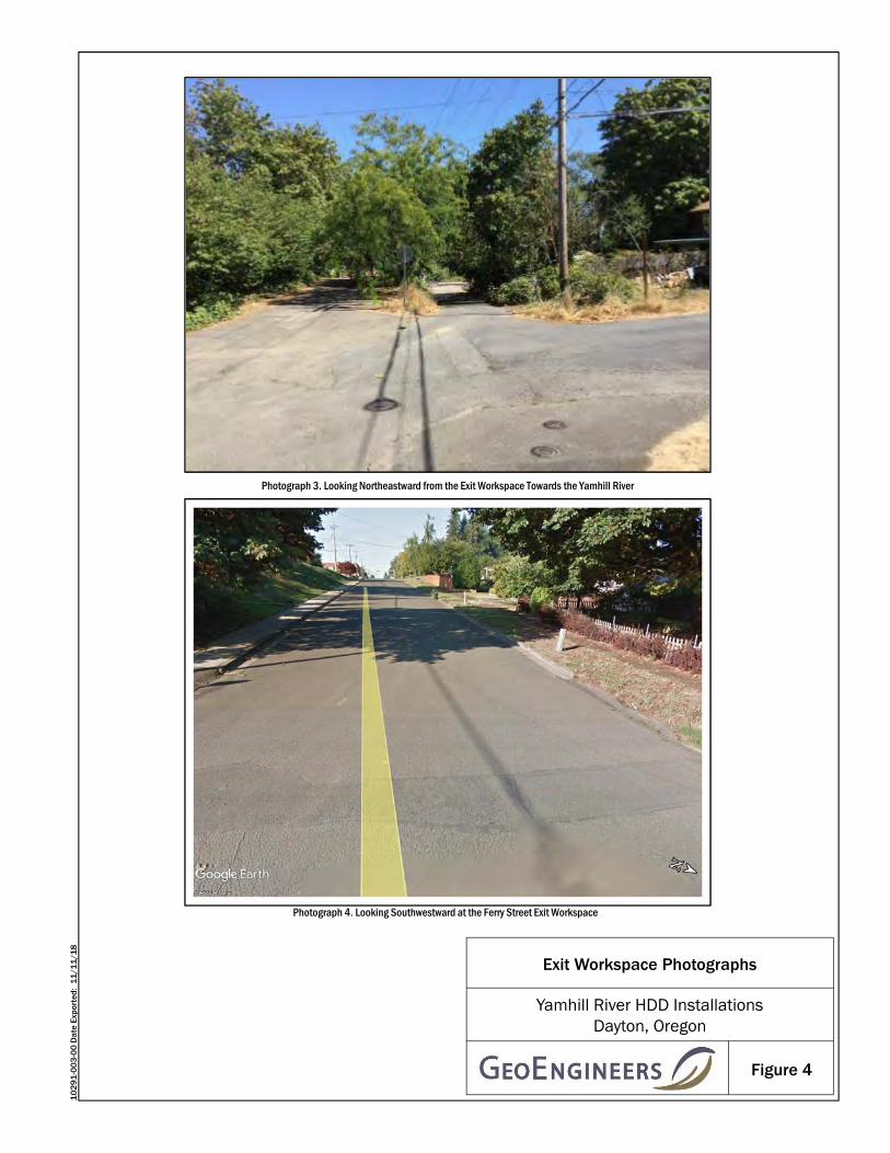
Figure 4
Exit Workspace Photographs
Photograph 3. Looking Northeastward from the Exit Workspace Towards the Yamhill River
Yamhill River HDD InstallationsDayton, Oregon
10
29
1-0
03
-00
Dat
e Ex
port
ed:
11
/11
/18
Photograph 4. Looking Southwestward at the Ferry Street Exit Workspace

MSP
S B-
1
B-3
B-2
B-1
Entr
y
Exit
Yam
hill
Rive
r
0
50
100
150
200
250
300
350
400
-25
0
25
50
75
100
125
150
175
01+00 02+00 03+00 04+00 05+00 06+00 07+00 08+00 09+00 10+00 11+00 12+00 13+00 14+00 15+00
Pres
sure
(psi
)
Elev
atio
n (ft
)
StationGround Surface Elevation (ft)
HDD Profile (ft)
Formation Limit Pressure (psi)
Estimated Annular Drilling Fluid Pressure (psi) for Pilot Hole
ESTIMATED ANNULAR DRILLING FLUID AND FORMATION LIMIT PRESSURES
Crossing Length (ft)Hole Diameter (in)Drill Pipe O.D. (in)Drilling Fluid Weight (ppg)Plastic Viscosity (cP)Yield Point (lb/100 sf)
11229.8755.000
9.51016
1029
1-00
3-00
JAH
18
1012
<Fr
acO
ut.v
5b10
.xls>
YAMHILL RIVER 18-INCH AND 20-INCH HDD INSTALLATIONS - PILOT HOLE (NE to SW)
FIGURE 5
1029
1-00
3-00
JAH
18
1012
<Fr
acO
ut.v
5b10
.xls>
YAMHILL RIVER 18-INCH AND 20-INCH HDD INSTALLATIONS - PILOT HOLE (NE to SW)

MSP
S B-
1
B-3
B-2
B-1 En
try
Exit
Yam
hill
Rive
r
0.0
2.0
4.0
6.0
8.0
10.0
12.0
14.0
16.0
-25
0
25
50
75
100
125
150
175
01+00 02+00 03+00 04+00 05+00 06+00 07+00 08+00 09+00 10+00 11+00 12+00 13+00 14+00 15+00
Fact
or o
f Saf
ety
Elev
atio
n (ft
)
StationGround Surface Elevation (ft)
HDD Profile (ft)
Factor of Safety = 2
Hydraulic Fracture Factor of Safety for Pilot Hole
Drilling Fluid Surface Release Factor of Safety for Pilot Hole
YAMHILL RIVER 18-INCH AND 20-INCH HDD INSTALLATIONS - PILOT HOLE (NE to SW)
HYDRAULIC FRACTURE AND DRILLING FLUID SURFACE RELEASE FACTORS OF SAFETY
YAMHILL RIVER 18-INCH AND 20-INCH HDD INSTALLATIONS - PILOT HOLE (NE to SW)
FIGURE 6
Crossing Length (ft)Hole Diameter (in)Drill Pipe O.D. (in)Drilling Fluid Weight (ppg)Plastic Viscosity (cP)Yield Point (lb/100 sf)
11229.8755.000
9.51016
1029
1-00
3-00
JAH
18
1012
<Fr
acO
ut.v
5b10
.xls>

AP
PE
ND
ICE
S

APPENDIX A Field Explorations and Laboratory Testing

March 26, 2019| Page A-1 File No. 10291-003-00
APPENDIX A FIELD EXPLORATIONS
We explored subsurface conditions by drilling two borings with a track-mounted drill rig using hollow-stem auger drilling and mud rotary drilling techniques on February 23, 2016, and September 12 and 13, 2018. Western States Soil Conservation of Hubbard Oregon drilled one boring (MSPS B-1) to a depth of 90 feet bgs on February 23, 2016. Holocene Drilling, Inc. of Puyallup, Washington drilled two borings to depths of 91.5 feet bgs (B-2 and B-3) and one boring to 31.5 feet bgs (B-1) on September 12 and 13, 2018. A representative from our Portland, Oregon office observed field activities, classified the soil encountered, obtained representative samples, observed groundwater conditions where possible and prepared a log of each exploration. The borings were backfilled with a bentonite and cement grout mixture at the conclusion of each exploration. The locations of each boring are shown in Figure 2.
Soil samples were obtained from the borings at 2.5- to 5-foot-depth intervals using split spoon and Dames & Moore (D&M) (2.4-inch inside-diameter, split barrel sampler) samplers. Soils encountered in the borings were classified in the field by a GeoEngineers, Inc. (GeoEngineers) representative in general accordance with ASTM International (ASTM) Standard Practices Test Method D2488, the Standard Practice for the Classification of Soils (Visual-Manual Procedure) which is described in Figure A-1. The boring logs are presented in Figures A-2 through A-5. Soil classifications and sampling intervals are shown in the boring logs. Inclined lines at the material contacts shown on the log indicate uncertainty as to the exact contact elevation, rather than the inclination of the contact itself.
Standard penetration tests (SPTs) were performed during soil drilling in general accordance with ASTM Test Method D1586. The sampler was driven with a 140-pound hammer falling 30 inches. The number of blows required to drive the sampler 1 foot, or as otherwise indicated, into the soils is shown adjacent to the sample symbols on the boring log. Disturbed samples were obtained from the split spoon sampler or D&M sampler for subsequent classification and index testing. Note that without use of a conversion calculation for blow counts where a D&M sampler was used, “N” values utilized for geotechnical engineering calculations are only applicable to the SPT tests where the split spoon samplers were used. The relative density of the SPT samples recovered at each interval was evaluated based on correlations with lab and field observations in general accordance with the values outlined in Table A-1 below.
TABLE A-1. CORRELATION BETWEEN BLOW COUNTS AND RELATIVE DENSITY *
Cohesive Soils (Clay/Silt)
Parameter Very Soft Soft Medium Stiff Stiff Very Stiff Hard
Blows, N < 2 2 – 4 4 - 8 8 – 16 16 - 32 >32
Cohesionless Soils (Gravel/Sand/Silty Sand) **
Parameter Very Loose Loose Medium Dense Dense Very Dense
Blows, N 0 – 4 4 – 10 10 – 30 30 - 50 > 50
Notes: * After Terzaghi, K and Peck, R.B., “Soil Mechanics in Engineering Practice,” John Wiley & Sons, Inc., 1962. ** Classification applies to soils containing additional constituents; that is, organic clay, silty or clayey sand, etc.

March 26, 2019| Page A-2 File No. 10291-003-00
LABORATORY TESTING
General
Samples obtained from the explorations were transported to our Portland, Oregon and Redmond, Washington laboratories and examined to confirm or modify field classifications, as well as to evaluate engineering properties of the samples. Representative soil samples were selected for laboratory testing consisting of sieve analyses, percent fines and moisture content determinations. The laboratory testing procedures are discussed in more detail below.
Percent Fines Determinations
Nine percent fines determinations were performed on soil samples obtained from the borings. The tests were used to evaluate the relative amounts of coarse and fine-grained particles present in the samples and were completed in general accordance with ASTM D1140. The results of the testing are presented in the boring logs at their respective sample depths.
Atterberg Limits Testing
Five Atterberg limits tests were performed on selected soil samples. The tests were used to classify and evaluate index properties of the soil. The liquid limit and the plastic limit were estimated through a procedure performed in general accordance with ASTM D4318. The results of the Atterberg limits testing are shown in Figures A-6 and A-7, and on the attached boring logs at their respective sample depths.
Moisture Content Determinations
Fourteen moisture content determinations were performed in conjunction with the percent fines testing and Atterberg limits tests. Moisture content determinations were performed in general accordance with ASTM D2216. The results of the moisture content determinations are shown in the attached boring logs at their respective sample depths.
Consolidated Undrained Triaxial Shear Strength Testing
One consolidated undrained (CU) triaxial shear strength test in accordance with ASTM D4767 on an undisturbed sample of silt soils obtained by sampling with a Shelby tube. The results of the CU triaxial shear strength test are shown in Figure A-8.

Measured groundwater level in exploration,well, or piezometer
Measured free product in well or piezometer
Distinct contact between soil strata
Approximate contact between soil strata
Contact between geologic units
SYMBOLS TYPICALDESCRIPTIONS
GW
GP
SW
SP
SM
FINEGRAINED
SOILS
SILTS ANDCLAYS
NOTE: Multiple symbols are used to indicate borderline or dual soil classifications
MORE THAN 50%RETAINED ONNO. 200 SIEVE
MORE THAN 50%PASSING
NO. 200 SIEVE
GRAVELAND
GRAVELLYSOILS
SC
LIQUID LIMITLESS THAN 50
(APPRECIABLE AMOUNTOF FINES)
(APPRECIABLE AMOUNTOF FINES)
COARSEGRAINED
SOILS
MAJOR DIVISIONSGRAPH LETTER
GM
GC
ML
CL
OL
SILTS ANDCLAYS
SANDS WITHFINES
SANDAND
SANDYSOILS
MH
CH
OH
PT
(LITTLE OR NO FINES)
CLEAN SANDS
GRAVELS WITHFINES
CLEAN GRAVELS
(LITTLE OR NO FINES)
WELL-GRADED GRAVELS, GRAVEL -SAND MIXTURES
CLAYEY GRAVELS, GRAVEL - SAND -CLAY MIXTURES
WELL-GRADED SANDS, GRAVELLYSANDS
POORLY-GRADED SANDS, GRAVELLYSAND
SILTY SANDS, SAND - SILT MIXTURES
CLAYEY SANDS, SAND - CLAYMIXTURES
INORGANIC SILTS, ROCK FLOUR,CLAYEY SILTS WITH SLIGHTPLASTICITY
INORGANIC CLAYS OF LOW TOMEDIUM PLASTICITY, GRAVELLYCLAYS, SANDY CLAYS, SILTY CLAYS,LEAN CLAYS
ORGANIC SILTS AND ORGANIC SILTYCLAYS OF LOW PLASTICITY
INORGANIC SILTS, MICACEOUS ORDIATOMACEOUS SILTY SOILS
INORGANIC CLAYS OF HIGHPLASTICITY
ORGANIC CLAYS AND SILTS OFMEDIUM TO HIGH PLASTICITY
PEAT, HUMUS, SWAMP SOILS WITHHIGH ORGANIC CONTENTSHIGHLY ORGANIC SOILS
SOIL CLASSIFICATION CHART
MORE THAN 50%OF COARSE
FRACTION RETAINEDON NO. 4 SIEVE
MORE THAN 50%OF COARSE
FRACTION PASSINGON NO. 4 SIEVE
SILTY GRAVELS, GRAVEL - SAND -SILT MIXTURES
POORLY-GRADED GRAVELS,GRAVEL - SAND MIXTURES
LIQUID LIMIT GREATERTHAN 50
Continuous Coring
Bulk or grab
Direct-Push
Piston
Shelby tube
Standard Penetration Test (SPT)
2.4-inch I.D. split barrel
Contact between soil of the same geologicunit
Material Description Contact
Graphic Log Contact
NOTE: The reader must refer to the discussion in the report text and the logs of explorations for a proper understanding of subsurface conditions.Descriptions on the logs apply only at the specific exploration locations and at the time the explorations were made; they are not warranted to berepresentative of subsurface conditions at other locations or times.
Groundwater Contact
Blowcount is recorded for driven samplers as the number ofblows required to advance sampler 12 inches (or distance noted).See exploration log for hammer weight and drop.
"P" indicates sampler pushed using the weight of the drill rig.
"WOH" indicates sampler pushed using the weight of thehammer.
Key to Exploration Logs
Figure A-1
Sampler Symbol Descriptions
ADDITIONAL MATERIAL SYMBOLS
NSSSMSHS
No Visible SheenSlight SheenModerate SheenHeavy Sheen
Sheen Classification
SYMBOLS
Asphalt Concrete
Cement Concrete
Crushed Rock/Quarry Spalls
Topsoil
GRAPH LETTER
AC
CC
SOD Sod/Forest Duff
CR
DESCRIPTIONSTYPICAL
TS
Laboratory / Field Tests%F%GALCACPCSDDDSHAMCMDMohsOCPMPIPPSATXUCVS
Percent finesPercent gravelAtterberg limitsChemical analysisLaboratory compaction testConsolidation testDry densityDirect shearHydrometer analysisMoisture contentMoisture content and dry densityMohs hardness scaleOrganic contentPermeability or hydraulic conductivityPlasticity indexPocket penetrometerSieve analysisTriaxial compressionUnconfined compressionVane shear
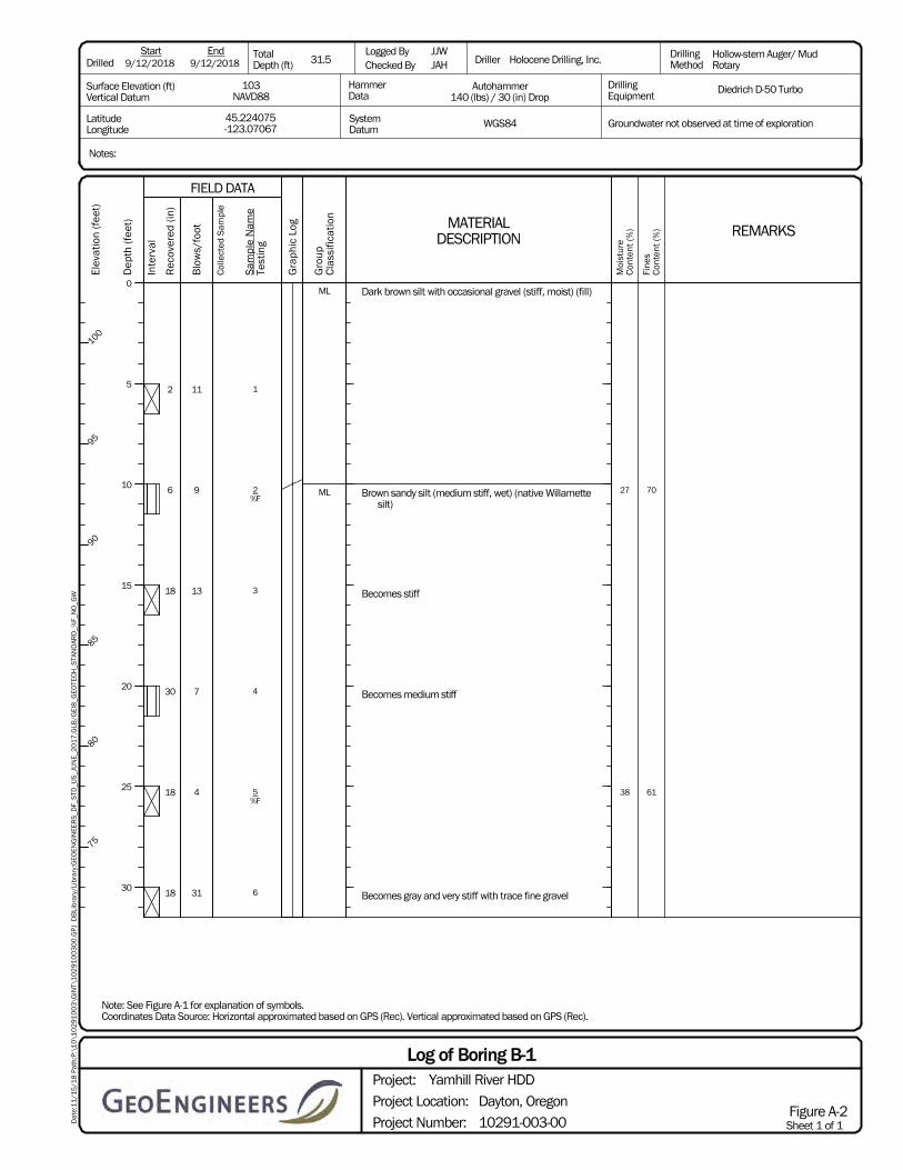
27
38
70
61
Dark brown silt with occasional gravel (stiff, moist) (fill)
Brown sandy silt (medium stiff, wet) (native Willamettesilt)
Becomes stiff
Becomes medium stiff
Becomes gray and very stiff with trace fine gravel
1
2%F
3
4
5%F
6
2
6
18
30
18
18
11
9
13
7
4
31
ML
ML
Notes:
31.5JJWJAH Holocene Drilling, Inc. Hollow-stem Auger/ Mud
Rotary
Diedrich D-50 TurboDrillingEquipment
Autohammer140 (lbs) / 30 (in) Drop
WGS8445.224075-123.07067
103NAVD88
LatitudeLongitude
Start TotalDepth (ft)
Logged ByChecked By
End
Surface Elevation (ft)Vertical Datum
Drilled
HammerData
SystemDatum
Driller DrillingMethod
Groundwater not observed at time of exploration
9/12/20189/12/2018
Note: See Figure A-1 for explanation of symbols.Coordinates Data Source: Horizontal approximated based on GPS (Rec). Vertical approximated based on GPS (Rec).
Sheet 1 of 1Project Number:
Project Location:
Project:
Dayton, Oregon
10291-003-00
Log of Boring B-1Yamhill River HDD
Figure A-2
Dat
e:1
1/1
5/1
8 P
ath:
P:\
10
\10
29
10
03
\GIN
T\1
02
91
00
30
0.G
PJ
DB
Libr
ary/
Libr
ary:
GEO
EN
GIN
EER
S_D
F_S
TD_U
S_J
UN
E_2
01
7.G
LB/G
EI8
_GEO
TEC
H_S
TAN
DAR
D_%
F_N
O_G
W
REMARKS
Moi
stur
eC
onte
nt (%
)
Fine
sC
onte
nt (%
)
FIELD DATA
MATERIALDESCRIPTION
Sam
ple
Nam
eTe
stin
g
Rec
over
ed (
in)
Inte
rval
Blo
ws/
foot
Col
lect
ed S
ampl
e
Dep
th (f
eet)
0
5
10
15
20
25
30
Gra
phic
Log
Gro
upC
lass
ifica
tion
Elev
atio
n (f
eet)
100
95
90
85
80
75
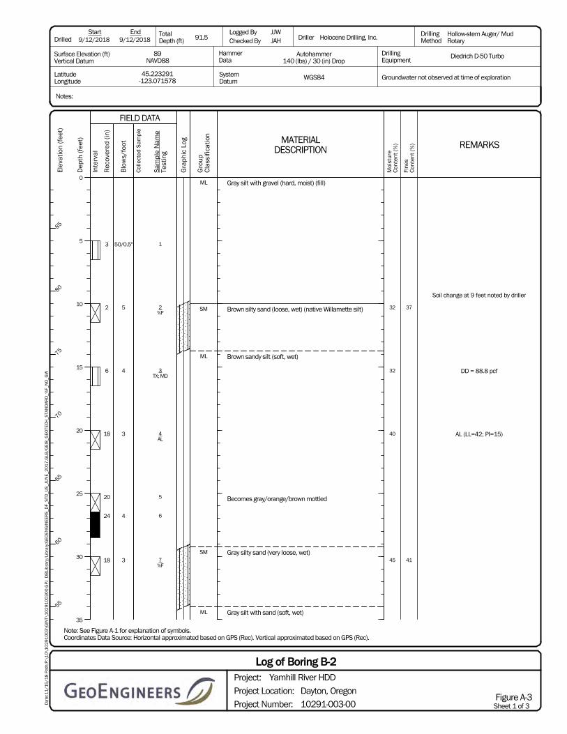
Soil change at 9 feet noted by driller
DD = 88.8 pcf
AL (LL=42; PI=15)
32
32
40
45
37
41
Gray silt with gravel (hard, moist) (fill)
Brown silty sand (loose, wet) (native Willamette silt)
Brown sandy silt (soft, wet)
Becomes gray/orange/brown mottled
Gray silty sand (very loose, wet)
Gray silt with sand (soft, wet)
1
2%F
3TX; MD
4AL
5
6
7%F
3
2
6
18
20
24
18
50/0.5"
5
4
3
4
3
ML
SM
ML
SM
ML
Notes:
91.5JJWJAH Holocene Drilling, Inc. Hollow-stem Auger/ Mud
Rotary
Diedrich D-50 TurboDrillingEquipment
Autohammer140 (lbs) / 30 (in) Drop
WGS8445.223291-123.071578
89NAVD88
LatitudeLongitude
Start TotalDepth (ft)
Logged ByChecked By
End
Surface Elevation (ft)Vertical Datum
Drilled
HammerData
SystemDatum
Driller DrillingMethod
Groundwater not observed at time of exploration
9/12/20189/12/2018
Note: See Figure A-1 for explanation of symbols.Coordinates Data Source: Horizontal approximated based on GPS (Rec). Vertical approximated based on GPS (Rec).
Sheet 1 of 3Project Number:
Project Location:
Project:
Dayton, Oregon
10291-003-00
Log of Boring B-2Yamhill River HDD
Figure A-3
Dat
e:1
1/1
5/1
8 P
ath:
P:\
10
\10
29
10
03
\GIN
T\1
02
91
00
30
0.G
PJ
DB
Libr
ary/
Libr
ary:
GEO
EN
GIN
EER
S_D
F_S
TD_U
S_J
UN
E_2
01
7.G
LB/G
EI8
_GEO
TEC
H_S
TAN
DAR
D_%
F_N
O_G
W
REMARKS
Moi
stur
eC
onte
nt (%
)
Fine
sC
onte
nt (%
)
FIELD DATA
MATERIALDESCRIPTION
Sam
ple
Nam
eTe
stin
g
Rec
over
ed (
in)
Inte
rval
Blo
ws/
foot
Col
lect
ed S
ampl
e
Dep
th (f
eet)
0
5
10
15
20
25
30
35
Gra
phic
Log
Gro
upC
lass
ifica
tion
Elev
atio
n (f
eet)
85
80
75
70
65
60
55
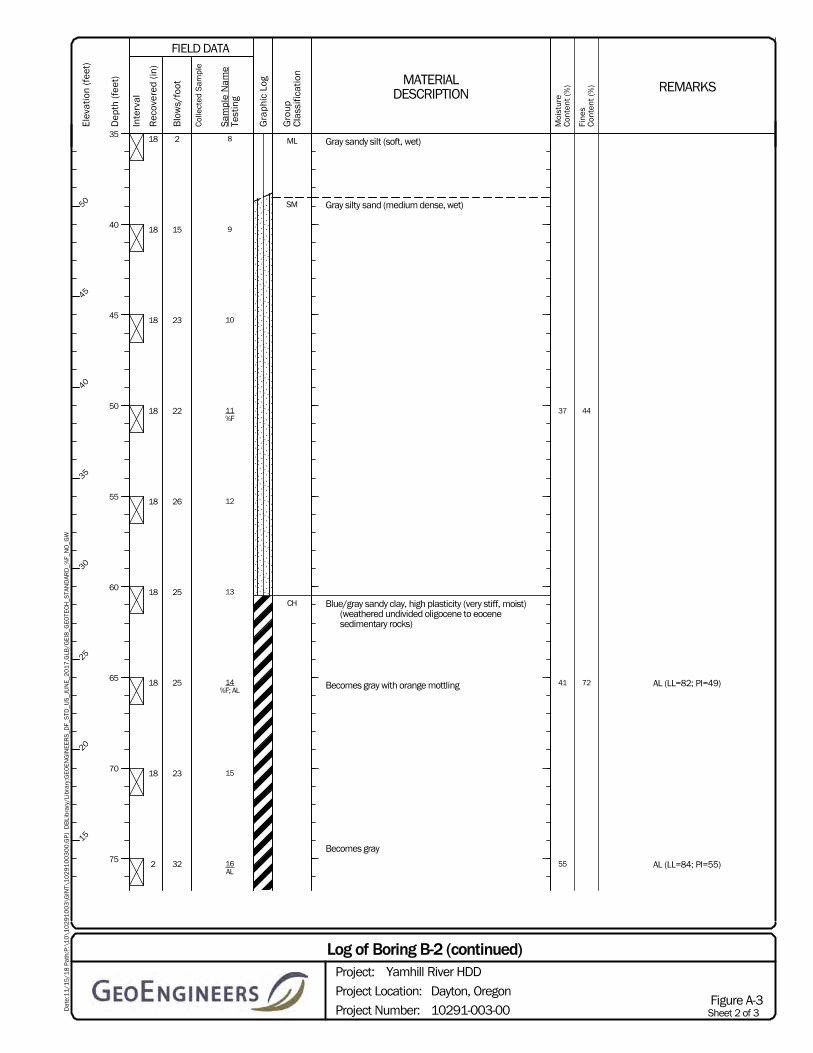
AL (LL=82; PI=49)
AL (LL=84; PI=55)
37
41
55
44
72
Gray sandy silt (soft, wet)
Gray silty sand (medium dense, wet)
Blue/gray sandy clay, high plasticity (very stiff, moist)(weathered undivided oligocene to eocenesedimentary rocks)
Becomes gray with orange mottling
Becomes gray
8
9
10
11%F
12
13
14%F; AL
15
16AL
18
18
18
18
18
18
18
18
2
2
15
23
22
26
25
25
23
32
ML
SM
CH
Sheet 2 of 3Project Number:
Project Location:
Project:
Dayton, Oregon
10291-003-00
Log of Boring B-2 (continued)Yamhill River HDD
Figure A-3
Dat
e:1
1/1
5/1
8 P
ath:
P:\
10
\10
29
10
03
\GIN
T\1
02
91
00
30
0.G
PJ
DB
Libr
ary/
Libr
ary:
GEO
EN
GIN
EER
S_D
F_S
TD_U
S_J
UN
E_2
01
7.G
LB/G
EI8
_GEO
TEC
H_S
TAN
DAR
D_%
F_N
O_G
W
REMARKS
Moi
stur
eC
onte
nt (%
)
Fine
sC
onte
nt (%
)
FIELD DATA
MATERIALDESCRIPTION
Sam
ple
Nam
eTe
stin
g
Rec
over
ed (
in)
Inte
rval
Blo
ws/
foot
Col
lect
ed S
ampl
e
Dep
th (f
eet)
35
40
45
50
55
60
65
70
75
Gra
phic
Log
Gro
upC
lass
ifica
tion
Elev
atio
n (f
eet)
50
45
40
35
30
25
20
15

Gray sandy clay, high plasticity (very stiff, moist)
Gray silty fine sand (medium dense, moist)
Gray silt with sand (very stiff, moist)
Gray clay, high plasticity (hard, moist)
17
18
19
6
18
18
27
24
36
CH
SM
ML
CH
Sheet 3 of 3Project Number:
Project Location:
Project:
Dayton, Oregon
10291-003-00
Log of Boring B-2 (continued)Yamhill River HDD
Figure A-3
Dat
e:1
1/1
5/1
8 P
ath:
P:\
10
\10
29
10
03
\GIN
T\1
02
91
00
30
0.G
PJ
DB
Libr
ary/
Libr
ary:
GEO
EN
GIN
EER
S_D
F_S
TD_U
S_J
UN
E_2
01
7.G
LB/G
EI8
_GEO
TEC
H_S
TAN
DAR
D_%
F_N
O_G
W
REMARKS
Moi
stur
eC
onte
nt (%
)
Fine
sC
onte
nt (%
)
FIELD DATA
MATERIALDESCRIPTION
Sam
ple
Nam
eTe
stin
g
Rec
over
ed (
in)
Inte
rval
Blo
ws/
foot
Col
lect
ed S
ampl
e
Dep
th (f
eet)
80
85
90
Gra
phic
Log
Gro
upC
lass
ifica
tion
Elev
atio
n (f
eet)
10
5
0

AL (LL=79; PI=53)40
37 59
Brown to gray sandy silt with trace fine gravel (mediumstiff, moist) (fill)
Brown sandy clay, high plasticity, with trace fine gravel(medium stiff, moist)
Gray with orange mottles sandy clay (medium stiff,moist) (native Willamette silt)
Brown with orange mottles sandy silt (medium stiff,wet)
Becomes gray and soft
Becomes medium stiff
1AL
2
3
4
5%F
6
6
18
18
18
18
7
8
6
4
5
7
ML
CH
CL
ML
Notes:
91.5JJWJAH Holocene Drilling, Inc. Hollow-stem Auger/ Mud
Rotary
Diedrich D-50 TurboDrillingEquipment
Autohammer140 (lbs) / 30 (in) Drop
WGS8445.222751-123.072202
90NAVD88
LatitudeLongitude
Start TotalDepth (ft)
Logged ByChecked By
End
Surface Elevation (ft)Vertical Datum
Drilled
HammerData
SystemDatum
Driller DrillingMethod
Groundwater not observed at time of exploration
9/13/20189/13/2018
Note: See Figure A-1 for explanation of symbols.Coordinates Data Source: Horizontal approximated based on GPS (Rec). Vertical approximated based on GPS (Rec).
Sheet 1 of 3Project Number:
Project Location:
Project:
Dayton, Oregon
10291-003-00
Log of Boring B-3Yamhill River HDD
Figure A-4
Dat
e:1
1/1
5/1
8 P
ath:
P:\
10
\10
29
10
03
\GIN
T\1
02
91
00
30
0.G
PJ
DB
Libr
ary/
Libr
ary:
GEO
EN
GIN
EER
S_D
F_S
TD_U
S_J
UN
E_2
01
7.G
LB/G
EI8
_GEO
TEC
H_S
TAN
DAR
D_%
F_N
O_G
W
REMARKS
Moi
stur
eC
onte
nt (%
)
Fine
sC
onte
nt (%
)
FIELD DATA
MATERIALDESCRIPTION
Sam
ple
Nam
eTe
stin
g
Rec
over
ed (
in)
Inte
rval
Blo
ws/
foot
Col
lect
ed S
ampl
e
Dep
th (f
eet)
0
5
10
15
20
25
30
35
Gra
phic
Log
Gro
upC
lass
ifica
tion
Elev
atio
n (f
eet)
85
80
75
70
65
60
55
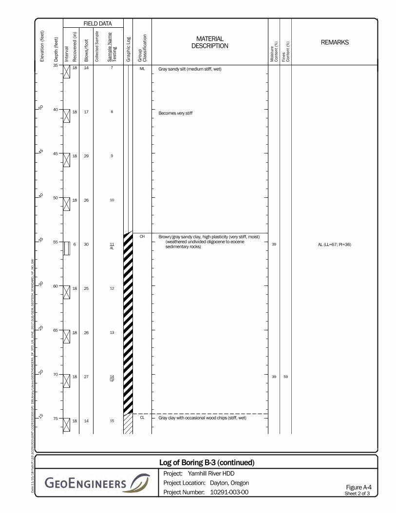
AL (LL=67; PI=36)39
39 59
Gray sandy silt (medium stiff, wet)
Becomes very stiff
Brown/gray sandy clay, high plasticity (very stiff, moist)(weathered undivided oligocene to eocenesedimentary rocks)
Gray clay with occasional wood chips (stiff, wet)
7
8
9
10
11AL
12
13
14%F
15
18
18
18
18
6
18
18
18
18
14
17
29
26
30
25
26
27
14
ML
CH
CL
Sheet 2 of 3Project Number:
Project Location:
Project:
Dayton, Oregon
10291-003-00
Log of Boring B-3 (continued)Yamhill River HDD
Figure A-4
Dat
e:1
1/1
5/1
8 P
ath:
P:\
10
\10
29
10
03
\GIN
T\1
02
91
00
30
0.G
PJ
DB
Libr
ary/
Libr
ary:
GEO
EN
GIN
EER
S_D
F_S
TD_U
S_J
UN
E_2
01
7.G
LB/G
EI8
_GEO
TEC
H_S
TAN
DAR
D_%
F_N
O_G
W
REMARKS
Moi
stur
eC
onte
nt (%
)
Fine
sC
onte
nt (%
)
FIELD DATA
MATERIALDESCRIPTION
Sam
ple
Nam
eTe
stin
g
Rec
over
ed (
in)
Inte
rval
Blo
ws/
foot
Col
lect
ed S
ampl
e
Dep
th (f
eet)
35
40
45
50
55
60
65
70
75
Gra
phic
Log
Gro
upC
lass
ifica
tion
Elev
atio
n (f
eet)
50
45
40
35
30
25
20
15

38 59
Gray clay with occasional wood chips (stiff, wet)
Becomes very stiff
16%F
17
18
6
18
18
16
24
28
CL
Sheet 3 of 3Project Number:
Project Location:
Project:
Dayton, Oregon
10291-003-00
Log of Boring B-3 (continued)Yamhill River HDD
Figure A-4
Dat
e:1
1/1
5/1
8 P
ath:
P:\
10
\10
29
10
03
\GIN
T\1
02
91
00
30
0.G
PJ
DB
Libr
ary/
Libr
ary:
GEO
EN
GIN
EER
S_D
F_S
TD_U
S_J
UN
E_2
01
7.G
LB/G
EI8
_GEO
TEC
H_S
TAN
DAR
D_%
F_N
O_G
W
REMARKS
Moi
stur
eC
onte
nt (%
)
Fine
sC
onte
nt (%
)
FIELD DATA
MATERIALDESCRIPTION
Sam
ple
Nam
eTe
stin
g
Rec
over
ed (
in)
Inte
rval
Blo
ws/
foot
Col
lect
ed S
ampl
e
Dep
th (f
eet)
80
85
90
Gra
phic
Log
Gro
upC
lass
ifica
tion
Elev
atio
n (f
eet)
10
5
0

25
27
35
35 80
12 inches gravel pavement
Dark brown silt with trace fine sand and occasionalgravel (medium stiff, moist) (fill)
With trace red-brown mottling
With occasional round gravel up to 3/4-inch, stiff
Brown silt with trace fine sand (medium stiff, moist)(alluvium)
Yellow-brown silt (stiff, moist) (Willamette Silt)
Grades to medium stiff
Interlayered yellow-brown silt with sand (medium stiff,moist to wet)
Grades to brown to red-brown
Grades to gray
Gray silt with fine sand and occasional interbeds ofblack poorly graded medium sand (stiff, moist to
1MC
2
3
4MC
5MC
6
7%F
8
9
10
10
18
12
12
16
12
16
12
16
12
6
7
12
5
9
6
5
10
40
18
GP
ML
ML
ML
ML
ML
Notes: D&M blowcount (N-values) reduced by approximately 50% to correlate with SPT N-values
91.5JLLJCV
Western States SoilConservation, Inc. Mud Rotary
CME-75 Truck #1DrillingEquipment
Autohammer140 (lbs) / 30 (in) Drop
WGS84
UndeterminedNAVD88
LatitudeLongitude
Start TotalDepth (ft)
Logged ByChecked By
End
Surface Elevation (ft)Vertical Datum
Drilled
HammerData
SystemDatum
Driller DrillingMethod
See "Remarks" section for groundwater observed
2/23/20162/23/2016
Note: See Figure A-1 for explanation of symbols.Coordinates Data Source: Horizontal approximated based on . Vertical approximated based on .
Sheet 1 of 3Project Number:
Project Location:
Project:
Dayton, Oregon
10291-003-00
Log of Boring MSPS-B-1Yamhill River HDD
Figure A-5
Dat
e:1
1/1
5/1
8 P
ath:
P:\
10
\10
29
10
03
\GIN
T\1
02
91
00
30
0.G
PJ
DB
Libr
ary/
Libr
ary:
GEO
EN
GIN
EER
S_D
F_S
TD_U
S_J
UN
E_2
01
7.G
LB/G
EI8
_GEO
TEC
H_S
TAN
DAR
D_%
F_N
O_G
W
REMARKS
Moi
stur
eC
onte
nt (%
)
Fine
sC
onte
nt (%
)
FIELD DATA
MATERIALDESCRIPTION
Sam
ple
Nam
eTe
stin
g
Rec
over
ed (
in)
Inte
rval
Blo
ws/
foot
Col
lect
ed S
ampl
e
Dep
th (f
eet)
0
5
10
15
20
25
30
35
Gra
phic
Log
Gro
upC
lass
ifica
tion
Elev
atio
n (f
eet)
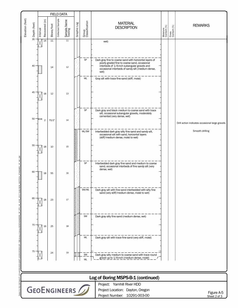
Drill action indicates occasional large gravels
Smooth drilling
wet)
Dark gray fine to coarse sand with horizontal layers ofpoorly graded fine to coarse sand, occasionalinterbeds of 1/4-inch subangular gravels andoccasional interbeds of sandy silt (medium dense,wet)
Gray silt with trace fine sand (stiff, moist)
Dark gray and black medium to coarse sand with tracesilt, occasional subangular gravels, moderatelycemented (very dense, wet)
Interbedded dark gray silty fine sand and sandy silt,occasional silt with sand, horizontal layers(stiff/medium dense, moist to wet)
Interbedded dark gray fine sand and medium to coarsesand, occasional interbeds of fine sandy silt (verydense, wet)
Dark gray silt with fine sand interbedded with silty finesand (very stiff/medium dense, moist to wet)
Dark gray silty fine sand (medium dense, wet)
Dark gray silt with trace fine sand (very stiff, moist)
Dark gray silty medium to coarse sand with trace roundgravel up to 1/4-inch (medium dense, moist)
11
12
13
14
15
16
17
18
19
14
18
2
18
18
18
16
11
14
12
70/2"
10
55
23
25
24
SP
ML
SP
ML/SM
SP
SM/ML
SM
ML
SM
ML
Sheet 2 of 3Project Number:
Project Location:
Project:
Dayton, Oregon
10291-003-00
Log of Boring MSPS-B-1 (continued)Yamhill River HDD
Figure A-5
Dat
e:1
1/1
5/1
8 P
ath:
P:\
10
\10
29
10
03
\GIN
T\1
02
91
00
30
0.G
PJ
DB
Libr
ary/
Libr
ary:
GEO
EN
GIN
EER
S_D
F_S
TD_U
S_J
UN
E_2
01
7.G
LB/G
EI8
_GEO
TEC
H_S
TAN
DAR
D_%
F_N
O_G
W
REMARKS
Moi
stur
eC
onte
nt (%
)
Fine
sC
onte
nt (%
)
FIELD DATA
MATERIALDESCRIPTION
Sam
ple
Nam
eTe
stin
g
Rec
over
ed (
in)
Inte
rval
Blo
ws/
foot
Col
lect
ed S
ampl
e
Dep
th (f
eet)
35
40
45
50
55
60
65
70
75
Gra
phic
Log
Gro
upC
lass
ifica
tion
Elev
atio
n (f
eet)
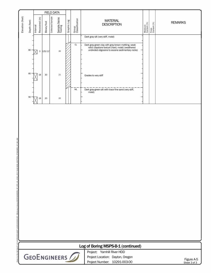
Dark gray silt (very stiff, moist)
Dark gray-green clay with gray-brown mottling, weakrelict claystone texture (hard, moist) (weatheredundivided oligocene to eocene sedimentary rocks)
Grades to very stiff
Dark gray-green silt with trace fine sand (very stiff,moist)
20
21
22
3
18
18
125/11"
30
20
CL
ML
Sheet 3 of 3Project Number:
Project Location:
Project:
Dayton, Oregon
10291-003-00
Log of Boring MSPS-B-1 (continued)Yamhill River HDD
Figure A-5
Dat
e:1
1/1
5/1
8 P
ath:
P:\
10
\10
29
10
03
\GIN
T\1
02
91
00
30
0.G
PJ
DB
Libr
ary/
Libr
ary:
GEO
EN
GIN
EER
S_D
F_S
TD_U
S_J
UN
E_2
01
7.G
LB/G
EI8
_GEO
TEC
H_S
TAN
DAR
D_%
F_N
O_G
W
REMARKS
Moi
stur
eC
onte
nt (%
)
Fine
sC
onte
nt (%
)
FIELD DATA
MATERIALDESCRIPTION
Sam
ple
Nam
eTe
stin
g
Rec
over
ed (
in)
Inte
rval
Blo
ws/
foot
Col
lect
ed S
ampl
e
Dep
th (f
eet)
80
85
90
Gra
phic
Log
Gro
upC
lass
ifica
tion
Elev
atio
n (f
eet)

Note: This report may not be reproduced, except in full, without written approval of GeoEngineers, Inc. Test results are applicable only to the specific sample on which they were performed, and should not be interpreted as representative of any other
samples obtained at other times, depths or locations, or generated by separate operations or processes.
The liquid limit and plasticity index were obtained in general accordance with ASTM D 4318.
Figure A-6
Atterberg Limits Test Results
Yamhill River HDD 18-inch and 20-inch HDDsDayton, Oregon
1029
1-00
3-00
Dat
e Ex
port
ed:
09/2
7/18
SymbolBoring
NumberDepth(feet)
Moisture Content
(%)
Liquid Limit(%)
Plasticity Index(%) Soil Description
B-2
B-2
B-2
20
65
75
40
41
55
42
82
84
15
49
55
Silt with sand (ML)
Fat clay with sand (CH)
Fat clay (CH)
0
10
20
30
40
50
60
0 10 20 30 40 50 60 70 80 90 100
PLAS
TICI
TY IN
DEX
LIQUID LIMIT
PLASTICITY CHART
CL-ML ML or OL
CL or OL
OH or MH
CH or OH

Note: This report may not be reproduced, except in full, without written approval of GeoEngineers, Inc. Test results are applicable only to the specific sample on which they were performed, and should not be interpreted as representative of any other
samples obtained at other times, depths or locations, or generated by separate operations or processes.
The liquid limit and plasticity index were obtained in general accordance with ASTM D 4318.
Figure A-7
Atterberg Limits Test Results
Yamhill River HDD 18-inch and 20-inch HDDsDayton, Oregon
1029
1-00
3-00
Dat
e Ex
port
ed:
09/2
7/18
SymbolBoring
NumberDepth(feet)
Moisture Content
(%)
Liquid Limit(%)
Plasticity Index(%) Soil Description
B-3
B-3
5
55
40
39
79
67
53
36
Sandy fat clay (CH)
Sandy fat clay (CH)
0
10
20
30
40
50
60
0 10 20 30 40 50 60 70 80 90 100
PLAS
TICI
TY IN
DEX
LIQUID LIMIT
PLASTICITY CHART
CL-ML ML or OL
CL or OL
OH or MH
CH or OH
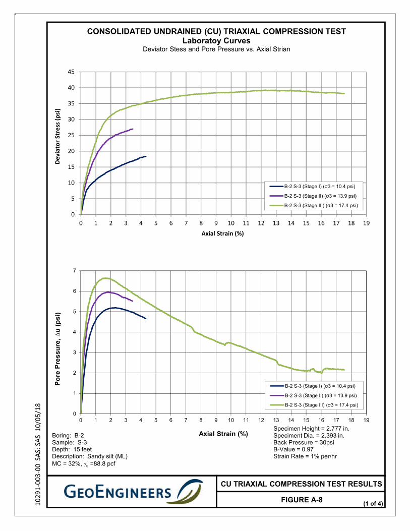
0
5
10
15
20
25
30
35
40
45
0 1 2 3 4 5 6 7 8 9 10 11 12 13 14 15 16 17 18 19
Deviator Stress (psi)
Axial Strain (%)
B-2 S-3 (Stage I) (σ3 = 10.4 psi)
B-2 S-3 (Stage II) (σ3 = 13.9 psi)
B-2 S-3 (Stage III) (σ3 = 17.4 psi)
0
1
2
3
4
5
6
7
0 1 2 3 4 5 6 7 8 9 10 11 12 13 14 15 16 17 18 19
Po
re P
ress
ure
, ∆
u (
psi
)
Axial Strain (%)
B-2 S-3 (Stage I) (σ3 = 10.4 psi)
B-2 S-3 (Stage II) (σ3 = 13.9 psi)
B-2 S-3 (Stage III) (σ3 = 17.4 psi)
CU TRIAXIAL COMPRESSION TEST RESULTS
FIGURE A-810291‐003‐00 SAS: SAS 10/05/18
Boring: B-2Sample: S-3Depth: 15 feet Description: Sandy silt (ML)MC = 32%, d =88.8 pcf
CONSOLIDATED UNDRAINED (CU) TRIAXIAL COMPRESSION TESTLaboratoy Curves
Deviator Stess and Pore Pressure vs. Axial Strian
Specimen Height = 2.777 in.Speciment Dia. = 2.393 in.Back Pressure = 30psiB-Value = 0.97Strain Rate = 1% per/hr
(1 of 4)

0
2
4
6
8
10
12
14
16
18
20
22
0 2 4 6 8 10 12 14 16 18 20 22 24 26 28 30 32 34 36 38
Sh
ear
Str
ess,
q (
psi
)
Mean Effective Confining Pressure, p' (psi)
Effective Stress Path
B-2 S-3 (Stage I) (σ3 = 10.4 psi)
B-2 S-3 (Stage II) (σ3 = 13.9 psi)
B-2 S-3 (Stage III) (σ3 = 17.4 psi)
0
1
2
3
4
5
0 1 2 3 4 5 6 7 8 9 10 11
Pri
nci
pal
Eff
ecti
ve
Str
ess
Rat
io
Axial Strain (%)
Principal Effective Stress Ratio vs. Axial Strain
B-2 S-3 (Stage I) (σ3 = 10.4 psi)
B-2 S-3 (Stage II) (σ3 = 13.9 psi)
B-2 S-3 (Stage III) (σ3 = 17.4 psi)
CU TRIAXIAL COMPRESSION TEST RESULTS
FIGURE A-910291‐003‐00 SAS: SAS 10/05/18
CONSOLIDATED UNDRAINED (CU) TRIAXIAL COMPRESSION TEST
(2 of 4)
Specimen Height = 2.777 in.Speciment Dia. = 2.393 in.Back Pressure = 30psiB-Value = 0.97Strain Rate = 1% per/hr
Boring: B-2Sample: S-3Depth: 15 feet Description: Sandy silt (ML)MC = 32%, d =88.8 pcf

0
10
20
30
40
50
0 5 10 15 20 25 30 35 40 45 50 55 60 65 70 75 80 85 90 95 100
Sh
ear
Str
ess,
τ(p
si)
Total Normal Stress, σ (psi)
Total Stress Envelope
B-2 S-3 (Stage II) (σ3 = 13.9 psi)
B-2 S-3 (Stage III) (σ3 = 17.4 psi)
Total Stress M-C Envelope
0
10
20
30
40
50
0 5 10 15 20 25 30 35 40 45 50 55 60 65 70 75 80 85 90 95 100
Sh
ear
Str
ess,
τ(p
si)
Effective Normal Stress, σ' (psi)
Effective Stress Envelope
B-2 S-3 (Stage II) (σ3 = 13.9 psi)
B-2 S-3 (Stage III) (σ3 = 17.4 psi)
Effective Stress M-C Envelope
Stress Path (Stage II)
Stress Path (Stage III)
CU TRIAXIAL COMPRESSION TEST RESULTS
10291‐003‐00 SAS: SAS 10/05/18
= 30 degreesc = 0 psi
' = 33 degreesc' = 1.9 psi
CONSOLIDATED UNDRAINED (CU) TRIAXIAL COMPRESSION TESTMohr-Coulomb Failure Envelopes
(maximum effective principal stress ratio failure criterion)
FIGURE A-10(3 of 4)
Specimen Height = 2.777 in.Speciment Dia. = 2.393 in.Back Pressure = 30psiB-Value = 0.97Strain Rate = 1% per/hr
Boring: B-2Sample: S-3Depth: 15 feet Description: Sandy silt (ML)MC = 32%, d =88.8 pcf
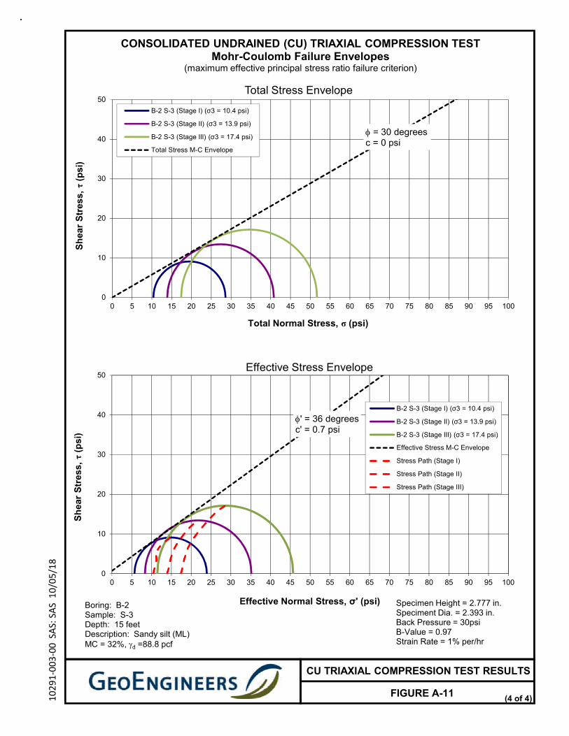
0
10
20
30
40
50
0 5 10 15 20 25 30 35 40 45 50 55 60 65 70 75 80 85 90 95 100
Sh
ear
Str
ess,
τ(p
si)
Total Normal Stress, σ (psi)
Total Stress Envelope
B-2 S-3 (Stage I) (σ3 = 10.4 psi)
B-2 S-3 (Stage II) (σ3 = 13.9 psi)
B-2 S-3 (Stage III) (σ3 = 17.4 psi)
Total Stress M-C Envelope
0
10
20
30
40
50
0 5 10 15 20 25 30 35 40 45 50 55 60 65 70 75 80 85 90 95 100
Sh
ear
Str
ess,
τ(p
si)
Effective Normal Stress, σ' (psi)
Effective Stress Envelope
B-2 S-3 (Stage I) (σ3 = 10.4 psi)
B-2 S-3 (Stage II) (σ3 = 13.9 psi)
B-2 S-3 (Stage III) (σ3 = 17.4 psi)
Effective Stress M-C Envelope
Stress Path (Stage I)
Stress Path (Stage II)
Stress Path (Stage III)
CU TRIAXIAL COMPRESSION TEST RESULTS
10291‐003‐00 SAS: SAS 10/05/18
= 30 degreesc = 0 psi
' = 36 degreesc' = 0.7 psi
CONSOLIDATED UNDRAINED (CU) TRIAXIAL COMPRESSION TESTMohr-Coulomb Failure Envelopes
(maximum effective principal stress ratio failure criterion)
FIGURE A-11(4 of 4)
Specimen Height = 2.777 in.Speciment Dia. = 2.393 in.Back Pressure = 30psiB-Value = 0.97Strain Rate = 1% per/hr
Boring: B-2Sample: S-3Depth: 15 feet Description: Sandy silt (ML)MC = 32%, d =88.8 pcf

APPENDIX B HDD Design Methodology, Drawings, and Calculations

March 26, 2019| Page B-1 File No. 10291-003-00
APPENDIX B HDD DESIGN METHODOLOGY, DRAWINGS, AND CALCULATIONS GENERAL
The following sections provide a discussion of the methodologies utilized as part of the design process for this project.
Hydraulic Fracture Calculations
The procedures used to evaluate the potential for drilling fluid loss through hydraulic fracturing are based primarily on research completed by Delft Geotechnics, as discussed in Appendix B of the U.S. Army Corps of Engineers (USACE) Report CPAR-GL-98 (Staheli, et al. 1998). The methodologies used to estimate the hydraulic fracture potential outlined in the research are based on cavity expansion theory. The cavity expansion model is used to estimate the maximum effective pressure in the drill hole before plastic deformation of the drill hole occurs.
In order to evaluate the hydraulic fracture and drilling fluid surface releases potential for a horizontal directional drilling (HDD) installation, assumptions must be made when selecting the input parameters. The assumptions used in the model include the extent and uniformity of soil layers, hydrostatic groundwater pressures, drilling fluid properties, penetration rates and drilling fluid flow rates. The soil strength properties are estimated based on interpretations of the boring logs and laboratory test results. The drilling fluid properties, penetration rates and pump rates are estimated based on generally accepted, Best Management Practices (BMPs) of the HDD industry. Consequently, the results of the evaluation are only estimates of the potential for hydraulic fracture and drilling fluid surface releases.
In addition, the drilling fluid properties are dependent on the field conditions and the construction practices of The HDD contractor and drilling fluid engineer. Changes in these properties can significantly affect the potential for hydraulic fracture and drilling fluid surface releases.
Based on the soil properties, rheological parameters and anticipated tool dimensions, the model considers the total and effective overburden stresses, shear strengths of the soil, and the estimated drilling fluid pressures along the drill path. A comparison is then made of the estimated drilling fluid pressures immediately behind the drill bit and the ability of the soil to resist plastic deformation. The evaluation considers only the hydraulic fracture potential during pilot hole operations assuming the drilling fluid returns are continuously maintained to the entry point.
HDD Design Calculations for HDPE Pipe
Our HDD design calculations were completed in accordance with applicable pipeline design criteria in ASTM design guidelines for HDD installations utilizing HDPE pipe (ASTM F1804-08 and ASTM F1962-05) and the generally accepted practices within the pipeline industry

38'
14'
150'
107'
25'
PROPOSEDHDD EXIT POINT
N. 10618.69111E. 11353.46722
PROPOSEDHDD ENTRY POINTN. 11437.11108E. 12111.71985
150'75'
75'
9'
10
76
2030
125/11"2425235510
70/2"12
14111840
5695
12
MSPS B-1SILT
CLAYSILTSILTY SANDSILTSILTY SANDSILT W/ SANDSAND
SILTY SANDSAND
SILTSAND W/ SILTSILT W/ SAND
SILT W/ SAND
SILTSILT W/ SAND
SILTPAVEMENT
14°
12°
38'
282416142726253026291714
754687
B-03
LEAN CLAY W/ OCCASIONAL WOOD CHIPS
SANDY FAT CLAY
SANDY SILT
SANDY LEAN CLAYSANDY FAT CLAY W/GRAVEL
SANDY SILT W/ GRAVEL
362427
3223252526222315
234
345
50/0.5"
B-02FAT CLAYSILT W/ SANDSILTY SAND
FAT SANDY CLAY
SILTY SAND
SILT W/ SANDSILTY SAND
SANDY SILT
SILTY SAND
SILT W/ GRAVEL
3147
13
911
B-01
SANDY SILT
SILT W/ GRAVEL
14'
9'
ITEM TOLERANCE
PILOT HOLE ENTRY ANGLEINCREASE ANGLE UP TO 1º (STEEPER), BUT NO DECREASEIN ANGLE ALLOWED.
PILOT HOLE ENTRY LOCATIONAS PER COORDINATES PROVIDED BY COMPANY WITH NOCHANGES WITHOUT COMPANY APPROVAL.
PILOT HOLE EXIT ANGLEINCREASE ANGLE UP TO 1º (STEEPER) OR DECREASE UP TO2º (FLATTER).
PILOT HOLE EXIT LOCATIONUP TO 20 FEET BEYOND OR 10 FEET SHORT OF THE EXITSTAKE. BETWEEN 2 FEET LEFT AND 5 FEET RIGHT OFCENTERLINE.
PILOT HOLE DEPTHUP TO 2 FEET ABOVE THE DESIGN DRILL PROFILE ALLOWED.UP TO 10 FEET BELOW THE DESIGN DRILL PROFILEALLOWED.
PILOT HOLE ALIGNMENTSHALL REMAIN WITHIN 2 FEET LEFT AND 5 FEET RIGHT OFTHE HDD ALIGNMENT.
MINIMUM RADIUSTHE MINIMUM ALLOWABLE 3 JOINT RADIUS SHALL NOT BELESS THAN 400 FEET
RECOMMENDED TOLERANCES
YAM
HILL
RIVE
R
PLAN
PROFILE NOTES:
1. CONTRACTOR SHALL ADHERE TO THE SPECIFICATIONS AND REQUIREMENTS PER CITY OF DAYTON SPECIFICATIONS,CONTRACT DOCUMENTS AND SPECIAL PERMIT CONDITIONS, EXCEPT AS NOTED ON THIS DRAWING.
2. CONTRACTOR IS RESPONSIBLE FOR CALLING OREGON ONE-CALL AND LOCATING ALL UNDERGROUND UTILITIESPRIOR TO BEGINNING CONSTRUCTION. IF ANY UTILITY IS LOCATED WITHIN 15 FEET OF THE DESIGNED HDD PROFILEAND ALIGNMENT, CONTRACTOR SHALL OBTAIN APPROVAL FROM CITY OF DAYTON PRIOR TO INITIATING HDDOPERATIONS.
3. IT IS THE CONTRACTOR'S RESPONSIBILITY TO IDENTIFY AND PROTECT ANY FOREIGN UTILITY THAT MAY BEAFFECTED BY THE HDD OPERATIONS.
4. ALL EQUIPMENT MUST ACCESS THE SITE ALONG THE CONSTRUCTION RIGHT-OF-WAY OR FROM APPROVED ACCESSROADS.
5. WORKSPACE: MAXIMUM WORKSPACE LIMITS ARE DEPICTED. RESTRICT CLEARING TO THE WORKSPACE INDICATEDAT THE ENTRY AND EXIT POINTS AND PRODUCT PIPE STRINGING AND FABRICATION AREA ALONG THECONSTRUCTION RIGHT-OF-WAY. CLEARING BETWEEN THE ENTRY AND EXIT POINTS REQUIRES PRIOR APPROVALFROM THE ENVIRONMENTAL INSPECTOR AND IS LIMITED TO THE AMOUNT NECESSARY TO STRING SURVEY WIRESAND INSTALL PUMPS AND PIPING TO OBTAIN WATER (WHERE APPROVED).
6. WATER SOURCE: DRILL WATER AND HYDROSTATIC TEST WATER SHALL BE OBTAINED FROM AN APPROVED SOURCE.
7. HYDROSTATIC TEST: PRE-INSTALLATION AND POST-INSTALLATION HYDROSTATIC TESTS SHALL BE CONDUCTED INACCORDANCE WITH THE HYDROSTATIC TEST PLAN. TEST WATER SHALL BE SAMPLED AND TESTED IN ACCORDANCEWITH PERMIT REQUIREMENTS. THE TEST WATER SHALL BE DISCHARGED IN AN UPLAND AREA INTO AN EROSIONCONTROL STRUCTURE OF STRAW BALES AND/OR SILT FENCES, GEOTEXTILE FILTER BAG, OR COLLECTED IN ATRUCK AND HAULED TO AN APPROVED DISPOSAL SITE. UPON COMPLETION OF DEWATERING AND DRYING, ACALIPER PIG SURVEY SHALL BE COMPLETED IN ACCORDANCE WITH THE CONTRACT DOCUMENTS.
8. SPILL-PREVENTION: REFUELING OF ALL EQUIPMENT SHALL BE COMPLETED IN ACCORDANCE WITH THE SPCC PLAN.
9. EROSION AND SEDIMENT CONTROL: CONTRACTOR SHALL SUPPLY, INSTALL AND MAINTAIN SEDIMENT CONTROLSTRUCTURES IN ACCORDANCE WITH CONTRACT DOCUMENTS. CONTRACTOR SHALL INSTALL ADDITIONAL EROSIONCONTROL STRUCTURES AS DIRECTED BY THE ENVIRONMENTAL INSPECTOR.
10. INSTALLATION: THE PIPE SECTION FOR THE DRILLED CROSSING SHALL BE MADE UP WITHIN THE APPROVEDCONSTRUCTION RIGHT-OF-WAY AT THE DRILL EXIT POINT AS SHOWN. AFTER THE PILOT HOLE IS COMPLETE,CONTRACTOR'S ACTUAL DRILL PROFILE SHALL BE SUBMITTED TO CITY OF DAYTON FOR APPROVAL. CONTRACTORSHALL ASSESS THE NEED FOR AND SUPPLY APPROPRIATE BALLAST DURING PULLBACK.
11. DRILLING FLUID DISPOSAL: CONTRACTOR SHALL DISPOSE OF EXCESS DRILLING FLUID AS DIRECTED BY THE CITYOF DAYTON REPRESENTATIVE IN ACCORDANCE WITH PERMIT CONDITIONS. UNDER NO CIRCUMSTANCES SHALLDRILLING FLUID BE DISPOSED OF IN WATER BODIES OR WETLANDS. ANY DRILLING FLUID WHICH INADVERTENTLYSURFACES AT POINTS OTHER THAN THE ENTRY OR EXIT POINTS SHALL BE CONTAINED AND COLLECTED TO THEEXTENT PRACTICAL AND DISPOSED OF AS DIRECTED BY THE CITY OF DAYTON REPRESENTATIVE IN ACCORDANCEWITH PERMIT CONDITIONS.
12. CLEANUP/STABILIZATION/RESTORATION: ALL DISTURBED AREAS SHALL BE RETURNED TO THE ORIGINALCONTOURS. DISTURBED AREAS SHALL BE SEEDED AS SPECIFIED IN THE CLEAN-UP AND RESTORATIONREQUIREMENTS. IF THE TERRAIN ALLOWS AND ACCESS IS PERMITTED, CONTRACTOR SHALL UTILIZE LOW GROUNDPRESSURE EQUIPMENT OR OTHER EQUIPMENT APPROVED BY OWNER, TO FACILITATE CONTAINMENT ANDCLEAN-UP OF ANY INADVERTENT RETURNS THAT OCCUR DURING THE HDD INSTALLATION PROCESS.
13. GEOTECHNICAL DATA: BORE HOLES ARE OFFSET FROM THE PIPELINE CENTERLINE AS SHOWN ON THE PLAN VIEW.THE GEOTECHNICAL INFORMATION PROVIDED ON THIS DRAWING IS A GENERAL SUMMARY. REFER TO THEAPPLICABLE GEOTECHNICAL REPORT IN THE CONTRACT DOCUMENTS FOR MORE DETAILED INFORMATION.
14. GROUND SURFACE DEM DOWNLOADED FROM HTTP://NATIONALMAP.GOV. AERIAL PHOTOS TAKEN FROM GOOGLEEARTH PRO © 2017, LICENSED TO GEOENGINEERS, INC., IMAGE DATED 05/22/17.
15. BASE FILES AND GROUND SURFACE SURVEY PROVIDED BY WESTECH ENGINEERING.
16. EXISTING PEDESTRIAN BRIDGE ELEVATIONS OBTAINED FROM: CITY OF DAYTON; STP EXPANSION & MODIFICATIONS;AS-BUILT (DATED JULY 1982)
DATUM:HORIZONTAL:VERTICAL:
LOCAL DATUM PROVIDED BY WESTECH ENGINEERINGNAVD 88
0
VERTICAL SCALE IN FEET
5050
0
HORIZONTAL SCALE IN FEET
5050
REFERENCE DRAWING TITLE
REFERENCESNO. DESCRIPTION
REVISIONSDesign
Checked
Approved
Drawn
Telephone (417) 831-9700Springfield, MO 65804Date
Date
Date
DateDrawing No.
Sheet
of
Project No.
3050 South Delaware
BY DATE CHK'D APP'DDRAWING NUMBER
Fax (417) 831-9777
10291-003-00
1 2
YAMHILL RIVER HDD CROSSINGSSITE PLAN AND PROFILE
18-INCH WATER MAIN HDDDAYTON, OREGON
JAH 10/24/18
JLE 03/22/19
BCR 03/22/19
--- 00/00/19
A ISSUED AS DRAFT JLE 11/15/18 BCRB ISSUED FOR BID JLE 03/07/19 BCRC ISSUED FOR BID (ADDED PUMP STATION AND GRAVITY SS) JLE 03/22/19 BCR
P:\1
0\10
2910
03\0
0\C
AD\H
DD
\Cro
ssin
g\Ya
mhi
llR
Iver
HD
D\Y
amhi
llR
iver
HD
D_1
8-In
ch_R
EVC
_IFB
.dw
g\TA
B:SH
EET
1m
odifi
edon
Mar
22,2
019
-9:4
4am
BASIS OF DESIGN:
1. PIPE WILL CONSIST OF 18" IRON PIPE SIZE (IPS) O.D. X 2.571" W.T., DR 7.0 PE4710 HIGH DENSITYPOLYETHENE
2. THE MAXIMUM ALLOWABLE OPERATING PRESSURE (MAOP) =180 psi.
3. THE ASSUMED MAXIMUM OPERATING TEMPERATURE = 73° FAHRENHEIT.
NOTE: THIS IS A FULL SIZE DRAWING THAT IS INTENDEDTO BE PRINTED ON A 22" X 34" SHEET OF PAPER.
THE STATIONING IS BASED ON AN ARBITRARY REFERENCE POINT*
B-1B-2B-3
PROPOSED 18" HORIZONTAL DIRECTIONAL DRILL - 1,121'
PROPOSED 18" HORIZONTAL DIRECTIONAL DRILL PROFILE(REFER TO BASIS OF DESIGN NOTES)
PROPOSED 0.67 ACRES IRREGULAR SHAPEDTEMPORARY HDD ENTRY WORKSPACE
PROPOSED TEMPORARY PIPE STRINGINGAND FABRICATION WORKSPACE (SEE SHEET 2 FOR LAYOUT)
PHT1
PHC1
MSPS B-1
CHLORINECONTACTCHAMBER
DE-CHLORINATIONBUILDINGS
PHC1
PHT1
PC1
PT1PC2
PT2
EXISTING PEDESTRIAN BRIDGE
PROPOSED HDD ENTRY POINT
PROPOSED HDD EXIT POINT
13.70° @ 600 FT. R.
PROPOSED 20" HDD
FENCE (TYP.)
OVERHEAD POWERLINES (TYP.)
600 FT R.
GROUND SURFACE (DEM)
YAMHILL RIVER(ELEV.=65' APPROXIMATE WATER LEVEL)
PROPERTY BOUNDARY (TYP.)
TYPE OF SOILSPT (N)
LEGEND
BORING LOCATION
MAJOR CONTOUR - 10' INTERVAL
MINOR CONTOUR - 2' INTERVAL
600 FT R.
FERRY STREET
COMMERCE STREET 1ST
STRE
ET
PROPOSED TEMPORARYHDD EXIT WORKSPACE
MAT
CHLI
NE
(SEE
SHEE
T2)
ABUTMENT ELEV.=100'
DEADMAN ELEV.=85'BENT ELEV.=87.42'
PIER ELEV.=75' PIER ELEV.=75'
BENT ELEV.=82.42'
DEADMAN ELEV.=83'
ABUTMENT ELEV.=94.5'
WATER LINE (TYP.)
DESCRIPTION STATION * (FT) ELEVATION (FT)
ENTRY 13+61.14 104.20
PVC 1 (12.00° @ 600 FT) 9+79.65 23.11
PVT 1 8+54.90 10.00
PVC 2 (14.00° @ 600 FT) 7+63.46 10.00
PVT 2 6+18.31 27.82
PHC 1 (13.70° @ 600 FT) 6+02.14 31.85
PHT 1 4+58.68 67.62
EXIT 2+40.00 122.14
DIRECTIONAL DRILL PIPE LENGTH = 1,143.62 FT
DIRECTIONAL DRILL DATA - ALIGNMENT BASED STATIONING18-INCH WATER MAIN HDD
HORIZONTAL DISTANCE = 1,121.14 FT
DESCRIPTION STATION (FT) ELEVATION (FT) RIGHT (FT)
ENTRY 13+61.14 104.20 0.00
PC 1 (12.00° @ 600 FT) 9+80.38 23.11 -23.54
PT 1 8+55.87 10.00 -31.24
PC 2 (14.00° @ 600 FT) 7+64.60 10.00 -36.89
PT 2 6+19.72 27.82 -45.85
PHC 1 (13.70° @ 600 FT) 6+03.59 31.85 -46.84
PHT 1 4+60.71 67.62 -38.58
EXIT 2+45.46 122.14 0.00
DIRECTIONAL DRILL PIPE LENGTH = 1,143.62 FT
DIRECTIONAL DRILL DATA - STRAIGHT LINE STATIONING18-INCH WATER MAIN HDD
HORIZONTAL DISTANCE = 1,115.69 FT
FLUID EQUILIBRIUMELEVATION (104.20')
GROUND SURFACE (SURVEY)STORM DRAIN (UNKNOWN DEPTH)
HDD ENTRY POINT DETAILSCALE: 1" = 30'
PROPOSED HDDENTRY POINT
EXISTING WATER LINE
0
SCALE IN FEET
50 50
ISSUED FOR BID
PROPOSED PUMP STATION
PROPOSED SEWERFORCE MAIN
PROPOSED GRAVITY SEWER FORCE MAIN (IE: 86.45')
STORMDRAIN (TYP.)
PROPOSED WATER MAIN
STORM SEWER (UNKNOWN DEPTH)
EXISTING SANITARYSEWER (TYP.)

PROPOSEDHDD ENTRY POINTN. 11437.11108E. 12111.71985
150'75'
75'
9'
NOTES:
1. ALL EQUIPMENT MUST ACCESS THE SITE ALONG THE CONSTRUCTION RIGHT-OF-WAY OR FROM APPROVED ACCESS ROADS.
2. GROUND SURFACE DEM DOWNLOADED FROM HTTP://NATIONALMAP.GOV. AERIAL PHOTOS TAKEN FROM GOOGLE EARTH PRO © 2017,LICENSED TO GEOENGINEERS, INC., IMAGE DATED 05/22/17.
3. BASE FILES AND GROUND SURFACE SURVEY PROVIDED BY WESTECH ENGINEERING.
PLAN
LEGENDBORING LOCATIONMAJOR CONTOUR - 10' INTERVALMINOR CONTOUR - 2' INTERVAL
DATUM:HORIZONTAL:VERTICAL:
LOCAL DATUM PROVIDED BY WESTECH ENGINEERINGNAVD 88
0
SCALE IN FEET
50 50NOTE: THIS IS A FULL SIZE DRAWING THAT IS INTENDEDTO BE PRINTED ON A 22" X 34" SHEET OF PAPER.
B-1
PROPOSED 18" HORIZONTALDIRECTIONAL DRILL - 1,121'
PROPOSED 0.67 ACRES IRREGULAR SHAPEDTEMPORARY HDD ENTRY WORKSPACE
PROPOSED TEMPORARY PRODUCT PIPE STRINGINGAND FABRICATION WORKSPACE (50' X 1,170')
CHLORINECONTACTCHAMBER
DE-CHLORINATIONBUILDINGS
PROPOSED 20" HDD
FENCE (TYP.)
STORM SEWER (TYP.)
OVERHEAD POWERLINES (TYP.)
PROPERTY BOUNDARY (TYP.)
MAT
CHLI
NE
(SEE
SHEE
T1)
REFERENCE DRAWING TITLE
REFERENCESNO. DESCRIPTION
REVISIONSDesign
Checked
Approved
Drawn
Telephone (417) 831-9700Springfield, MO 65804Date
Date
Date
DateDrawing No.
Sheet
of
Project No.
3050 South Delaware
BY DATE CHK'D APP'DDRAWING NUMBER
Fax (417) 831-9777
10291-003-00
2 2
YAMHILL RIVER HDD CROSSINGSSTRINGING WORKSPACE
18-INCH WATER MAIN HDDDAYTON, OREGON
JAH 10/24/18
JLE 03/22/19
JAH 03/22/19
--- 00/00/19
A ISSUED AS DRAFT JLE 11/15/18 BCRB ISSUED FOR BID JLE 03/07/19 BCRC ISSUED FOR BID (ADDED PS AND GRAVITY SEWER LINE) JLE 03/22/19 BCR
P:\1
0\10
2910
03\0
0\C
AD\H
DD
\Cro
ssin
g\Ya
mhi
llR
Iver
HD
D\Y
amhi
llR
iver
HD
D_1
8-In
ch_R
EVC
_IFB
.dw
g\TA
B:SH
EET
2Pl
anO
nly
mod
ified
onM
ar22
,201
9-8
:18a
m
ISSUED FOR BID

38'
14'
150'
107'
25'
PROPOSEDHDD EXIT POINT
N. 10610.70735E. 11359.48882
PROPOSEDHDD ENTRY POINTN. 11430.78049E. 12119.46088
150'75'
75'
10
76
2030
125/11"2425235510
70/2"12
14111840
5695
12
MSPS B-1SILT
CLAYSILTSILTY SANDSILTSILTY SANDSILT W/ SANDSAND
SILTY SANDSAND
SILTSAND W/ SILTSILT W/ SAND
SILT W/ SAND
SILTSILT W/ SAND
SILT12 INCHES GRAVEL PAVEMENT
14°
12°
38'
362427
3223252526222315
234
345
50/0.5"
B-02FAT CLAYSILT W/ SANDSILTY SAND
SANDY FAT CLAY
SILTY SAND
SILT W/ SANDSILTY SAND
SANDY SILT
SILTY SAND
SILT W/ GRAVEL
3147
13
911
B-01
SANDY SILT
SILT W/ GRAVEL
282416142726253026291714
754687
B-03
LEAN CLAY W/ OCCASIONAL WOOD CHIPS
SANDY FAT CLAY
SANDY SILT
SANDY LEAN CLAY
SANDY FAT CLAY W/ GRAVELSANDY SILT W/ GRAVEL
12'
19'
ITEM TOLERANCE
PILOT HOLE ENTRY ANGLEINCREASE ANGLE UP TO 1º (STEEPER), BUT NO DECREASEIN ANGLE ALLOWED.
PILOT HOLE ENTRY LOCATIONAS PER COORDINATES PROVIDED BY COMPANY WITH NOCHANGES WITHOUT COMPANY APPROVAL.
PILOT HOLE EXIT ANGLEINCREASE ANGLE UP TO 1º (STEEPER) OR DECREASE UP TO2º (FLATTER).
PILOT HOLE EXIT LOCATIONUP TO 20 FEET BEYOND OR 10 FEET SHORT OF THE EXITSTAKE. BETWEEN 2 FEET RIGHT AND 5 FEET LEFT OFCENTERLINE.
PILOT HOLE DEPTHUP TO 2 FEET ABOVE THE DESIGN DRILL PROFILE ALLOWED.UP TO 10 FEET BELOW THE DESIGN DRILL PROFILEALLOWED.
PILOT HOLE ALIGNMENTSHALL REMAIN WITHIN 2 FEET RIGHT AND 5 FEET LEFT OFTHE HDD ALIGNMENT.
MINIMUM RADIUSTHE MINIMUM ALLOWABLE 3 JOINT RADIUS SHALL NOT BELESS THAN 400 FEET
RECOMMENDED TOLERANCES
YAM
HILL
RIVE
R
PLAN
PROFILE
DATUM:HORIZONTAL:VERTICAL:
LOCAL DATUM PROVIDED BY WESTECH ENGINEERINGNAVD 88
0
VERTICAL SCALE IN FEET
5050
0
HORIZONTAL SCALE IN FEET
5050
NOTE: THIS IS A FULL SIZE DRAWING THAT IS INTENDEDTO BE PRINTED ON A 22" X 34" SHEET OF PAPER.
THE STATIONING IS BASED ON AN ARBITRARY REFERENCE POINT*
B-1B-2B-3
PROPOSED 20" HORIZONTAL DIRECTIONAL DRILL - 1,122'
PROPOSED 20" HORIZONTAL DIRECTIONAL DRILL PROFILE(REFER TO BASIS OF DESIGN NOTES)
PROPOSED 0.67 ACRES IRREGULAR SHAPEDTEMPORARY HDD ENTRY WORKSPACE
PROPOSED TEMPORARY PIPE STRINGINGAND FABRICATION WORKSPACE (SEE SHEET 2 FOR LAYOUT)
PHT1
PHC1
MSPS B-1
CHLORINECONTACTCHAMBER
DE-CHLORINATIONBUILDINGS
PHC1
PHT1
PC1
PT1PC2
PT2
EXISTING PEDESTRIAN BRIDGE
PROPOSED HDD ENTRY POINT
PROPOSED HDD EXIT POINT
13.70° @ 600 FT. R.
PROPOSED 18" HDD
FENCE (TYP.)
OVERHEAD POWERLINES (TYP.)
600 FT R.
GROUND SURFACE (DEM)
PROPERTY BOUNDARY (TYP.)
TYPE OF SOILSPT (N)
LEGEND
BORING LOCATION
MAJOR CONTOUR - 10' INTERVAL
MINOR CONTOUR - 2' INTERVAL
600 FT R.
FERRY STREET
COMMERCE STREET
1ST
STRE
ET
PROPOSED TEMPORARYHDD EXIT WORKSPACE
MAT
CHLI
NE
(SEE
SHEE
T2)
DESCRIPTION STATION * (FT) ELEVATION (FT)
ENTRY 13+61.14 105.29
PC 1 (12.00° @ 600 FT) 9+74.53 23.11
PT 1 8+49.79 10.00
PC 2 (14.00° @ 600 FT) 7+69.30 10.00
PT 2 6+24.15 27.82
PHC 1 (13.70° @ 600 FT) 6+02.12 33.31
PHT 1 4+58.66 69.08
EXIT 2+39.19 123.80
DIRECTIONAL DRILL PIPE LENGTH = 1,144.75 FT
DIRECTIONAL DRILL DATA - ALIGNMENT BASED STATIONING 14-INCH ID SEWER HDD
HORIZONTAL DISTANCE = 1,121.95 FT
DESCRIPTION STATION (FT) ELEVATION (FT) RIGHT (FT)
ENTRY 13+61.14 105.29 0.00
PC 1 (12.00° @ 600 FT) 9+75.27 23.11 -23.91
PT 1 8+50.77 10.00 -31.62
PC 2 (14.00° @ 600 FT) 7+70.43 10.00 -36.60
PT 2 6+25.56 27.82 -45.58
PHC 1 (13.70° @ 600 FT) 6+03.57 33.31 -46.94
PHT 1 4+60.69 69.08 -38.69
EXIT 2+44.66 123.80 0.00
DIRECTIONAL DRILL PIPE LENGTH = 1,144.75 FT
DIRECTIONAL DRILL DATA - STRAIGHT LINE STATIONING14-INCH ID SEWER HDD
HORIZONTAL DISTANCE = 1,116.48 FT
REFERENCE DRAWING TITLE
REFERENCESNO. DESCRIPTION
REVISIONSDesign
Checked
Approved
Drawn
Telephone (417) 831-9700Springfield, MO 65804Date
Date
Date
DateDrawing No.
Sheet
of
Project No.
3050 South Delaware
BY DATE CHK'D APP'DDRAWING NUMBER
Fax (417) 831-9777
10291-003-00
1 2
YAMHILL RIVER HDD CROSSINGSSITE PLAN AND PROFILE
20-INCH SEWER FORCE MAIN HDDDAYTON, OREGON
JAH 10/24/18
JLE 03/22/19
BCR 03/22/19
- 00/00/19
A ISSUED AS DRAFT JLE 11/15/18 BCRB ISSUED FOR BID JLE 03/01/19 BCRC ISSUED FOR BID (ADDED PUMP STATION AND GRAVITY SS) JLE 03/22/19 BCR
P:\1
0\10
2910
03\0
0\C
AD\H
DD
\Cro
ssin
g\Ya
mhi
llR
Iver
HD
D\Y
amhi
llR
iver
HD
D_2
0-In
ch_R
EVC
_IFB
.dw
g\TA
B:SH
EET
1m
odifi
edon
Mar
22,2
019
-8:5
2am
NOTES:
1. CONTRACTOR SHALL ADHERE TO THE SPECIFICATIONS AND REQUIREMENTS PER CITY OF DAYTONSPECIFICATIONS, CONTRACT DOCUMENTS AND SPECIAL PERMIT CONDITIONS, EXCEPT AS NOTED ON THISDRAWING.
2. CONTRACTOR IS RESPONSIBLE FOR CALLING OREGON ONE-CALL AND LOCATING ALL UNDERGROUNDUTILITIES PRIOR TO BEGINNING CONSTRUCTION. IF ANY UTILITY IS LOCATED WITHIN 15 FEET OF THEDESIGNED HDD PROFILE AND ALIGNMENT, CONTRACTOR SHALL OBTAIN APPROVAL FROM CITY OF DAYTONPRIOR TO INITIATING HDD OPERATIONS.
3. IT IS THE CONTRACTOR'S RESPONSIBILITY TO IDENTIFY AND PROTECT ANY FOREIGN UTILITY THAT MAY BEAFFECTED BY THE HDD OPERATIONS.
4. ALL EQUIPMENT MUST ACCESS THE SITE ALONG THE CONSTRUCTION RIGHT-OF-WAY OR FROM APPROVEDACCESS ROADS.
5. WORKSPACE: MAXIMUM WORKSPACE LIMITS ARE DEPICTED. RESTRICT CLEARING TO THE WORKSPACEINDICATED AT THE ENTRY AND EXIT POINTS AND PRODUCT PIPE STRINGING AND FABRICATION AREA ALONGTHE CONSTRUCTION RIGHT-OF-WAY. CLEARING BETWEEN THE ENTRY AND EXIT POINTS REQUIRES PRIORAPPROVAL FROM THE ENVIRONMENTAL INSPECTOR AND IS LIMITED TO THE AMOUNT NECESSARY TO STRINGSURVEY WIRES AND INSTALL PUMPS AND PIPING TO OBTAIN WATER (WHERE APPROVED).
6. WATER SOURCE: DRILL WATER AND HYDROSTATIC TEST WATER SHALL BE OBTAINED FROM AN APPROVEDSOURCE.
7. HYDROSTATIC TEST: PRE-INSTALLATION AND POST-INSTALLATION HYDROSTATIC TESTS SHALL BE CONDUCTEDIN ACCORDANCE WITH THE HYDROSTATIC TEST PLAN. TEST WATER SHALL BE SAMPLED AND TESTED INACCORDANCE WITH PERMIT REQUIREMENTS. THE TEST WATER SHALL BE DISCHARGED IN AN UPLAND AREAINTO AN EROSION CONTROL STRUCTURE OF STRAW BALES AND/OR SILT FENCES, GEOTEXTILE FILTER BAG,OR COLLECTED IN A TRUCK AND HAULED TO AN APPROVED DISPOSAL SITE. UPON COMPLETION OFDEWATERING AND DRYING, A CALIPER PIG SURVEY SHALL BE COMPLETED IN ACCORDANCE WITH THECONTRACT DOCUMENTS.
8. SPILL-PREVENTION: REFUELING OF ALL EQUIPMENT SHALL BE COMPLETED IN ACCORDANCE WITH THE SPCCPLAN.
9. EROSION AND SEDIMENT CONTROL: CONTRACTOR SHALL SUPPLY, INSTALL AND MAINTAIN SEDIMENTCONTROL STRUCTURES IN ACCORDANCE WITH CONTRACT DOCUMENTS. CONTRACTOR SHALL INSTALLADDITIONAL EROSION CONTROL STRUCTURES AS DIRECTED BY THE ENVIRONMENTAL INSPECTOR.
10. INSTALLATION: THE PIPE SECTION FOR THE DRILLED CROSSING SHALL BE MADE UP WITHIN THE APPROVEDCONSTRUCTION RIGHT-OF-WAY AT THE DRILL EXIT POINT AS SHOWN. AFTER THE PILOT HOLE IS COMPLETE,CONTRACTOR'S ACTUAL DRILL PROFILE SHALL BE SUBMITTED TO CITY OF DAYTON FOR APPROVAL.CONTRACTOR SHALL ASSESS THE NEED FOR AND SUPPLY APPROPRIATE BALLAST DURING PULLBACK.
11. DRILLING FLUID DISPOSAL: CONTRACTOR SHALL DISPOSE OF EXCESS DRILLING FLUID AS DIRECTED BY THECITY OF DAYTON REPRESENTATIVE IN ACCORDANCE WITH PERMIT CONDITIONS. UNDER NO CIRCUMSTANCESSHALL DRILLING FLUID BE DISPOSED OF IN WATER BODIES OR WETLANDS. ANY DRILLING FLUID WHICHINADVERTENTLY SURFACES AT POINTS OTHER THAN THE ENTRY OR EXIT POINTS SHALL BE CONTAINED ANDCOLLECTED TO THE EXTENT PRACTICAL AND DISPOSED OF AS DIRECTED BY THE CITY OF DAYTONREPRESENTATIVE IN ACCORDANCE WITH PERMIT CONDITIONS.
12. CLEANUP/STABILIZATION/RESTORATION: ALL DISTURBED AREAS SHALL BE RETURNED TO THE ORIGINALCONTOURS. DISTURBED AREAS SHALL BE SEEDED AS SPECIFIED IN THE CLEAN-UP AND RESTORATIONREQUIREMENTS. IF THE TERRAIN ALLOWS AND ACCESS IS PERMITTED, CONTRACTOR SHALL UTILIZE LOWGROUND PRESSURE EQUIPMENT OR OTHER EQUIPMENT APPROVED BY OWNER, TO FACILITATE CONTAINMENTAND CLEAN-UP OF ANY INADVERTENT RETURNS THAT OCCUR DURING THE HDD INSTALLATION PROCESS.
13. GEOTECHNICAL DATA: BORE HOLES ARE OFFSET FROM THE PIPELINE CENTERLINE AS SHOWN ON THE PLANVIEW. THE GEOTECHNICAL INFORMATION PROVIDED ON THIS DRAWING IS A GENERAL SUMMARY. REFER TOTHE APPLICABLE GEOTECHNICAL REPORT IN THE CONTRACT DOCUMENTS FOR MORE DETAILEDINFORMATION.
14. GROUND SURFACE DEM DOWNLOADED FROM HTTP://NATIONALMAP.GOV. AERIAL PHOTOS TAKEN FROMGOOGLE EARTH PRO © 2017, LICENSED TO GEOENGINEERS, INC., IMAGE DATED 05/22/17.
15. BASE FILES AND GROUND SURFACE SURVEY PROVIDED BY WESTECH ENGINEERING.
16. EXISTING PEDESTRIAN BRIDGE ELEVATIONS OBTAINED FROM: CITY OF DAYTON; STP EXPANSION &MODIFICATIONS; AS-BUILT (DATED JULY 1982)
BASIS OF DESIGN:
1. PIPE WILL CONSIST OF 20" IRON PIPE SIZE (IPS) O.D. X 2.857" W.T., DR 7.0 PE4710 HIGH DENSITYPOLYETHENE
2. THE MAXIMUM ALLOWABLE OPERATING PRESSURE (MAOP) =150 psi.
3. THE ASSUMED MAXIMUM OPERATING TEMPERATURE = 73° FAHRENHEIT.
GROUND SURFACE (SURVEY)
YAMHILL RIVER(ELEV.=65' APPROXIMATE WATER LEVEL)
ABUTMENT ELEV.=100'
DEADMAN ELEV.=85'BENT ELEV.=87.42'
PIER ELEV.=75' PIER ELEV.=75'
BENT ELEV.=82.42'
DEADMAN ELEV.=83'
ABUTMENT ELEV.=94.5'
WATER LINE (TYP.)
FLUID EQUILIBRIUMELEVATION (105.29')
STORM SEWER (UNKNOWN DEPTH)
STORM SEWER (UNKNOWN DEPTH)
STORM DRAIN (TYP.)
SEE ENTRY POINT DETAIL
HDD ENTRY POINT DETAILSCALE: 1" = 30'
PROPOSED HDDENTRY POINT
EXISTING WATER LINE
0
SCALE IN FEET
50 50
ISSUED FOR BID
PROPOSED PUMP STATION
PROPOSED SEWERFORCE MAIN
STORMDRAIN (TYP.)
STORM DRAIN (UNKNOWN DEPTH)
PROPOSED GRAVITY SEWER FORCE MAIN (IE: 86.46')
PROPOSED WATER MAINEXISTING SANITARYSEWER (TYP.)

PROPOSEDHDD ENTRY POINTN. 11430.78049E. 12119.46088
150'75'
75'
19'
NOTES:
1. ALL EQUIPMENT MUST ACCESS THE SITE ALONG THE CONSTRUCTION RIGHT-OF-WAY OR FROM APPROVED ACCESS ROADS.
2. GROUND SURFACE DEM DOWNLOADED FROM HTTP://NATIONALMAP.GOV. AERIAL PHOTOS TAKEN FROM GOOGLE EARTH PRO © 2017,LICENSED TO GEOENGINEERS, INC., IMAGE DATED 05/22/17.
3. BASE FILES AND GROUND SURFACE SURVEY PROVIDED BY WESTECH ENGINEERING.
PLAN
LEGENDBORING LOCATION
MINOR CONTOUR - 2' INTERVAL
DATUM:HORIZONTAL:VERTICAL:
LOCAL DATUM PROVIDED BY WESTECH ENGINEERINGNAVD 88
NOTE: THIS IS A FULL SIZE DRAWING THAT IS INTENDEDTO BE PRINTED ON A 22" X 34" SHEET OF PAPER.
B-1
PROPOSED 20" HORIZONTALDIRECTIONAL DRILL - 1,122'
PROPOSED 0.67 ACRES IRREGULAR SHAPEDTEMPORARY HDD ENTRY WORKSPACE
PROPOSED TEMPORARY PRODUCT PIPE STRINGINGAND FABRICATION WORKSPACE (50' X 1,170')
CHLORINECONTACTCHAMBER
DE-CHLORINATIONBUILDINGS
PROPOSED 18" HDD
FENCE (TYP.)
STORM SEWER (TYP.)
OVERHEAD POWERLINES (TYP.)
PROPERTY BOUNDARY (TYP.)
MAT
CHLI
NE
(SEE
SHEE
T1)
REFERENCE DRAWING TITLE
REFERENCESNO. DESCRIPTION
REVISIONSDesign
Checked
Approved
Drawn
Telephone (417) 831-9700Springfield, MO 65804Date
Date
Date
DateDrawing No.
Sheet
of
Project No.
3050 South Delaware
BY DATE CHK'D APP'DDRAWING NUMBER
Fax (417) 831-9777
10291-003-00
2 2
YAMHILL RIVER HDD CROSSINGSSTRINGING WORKSPACE
20-INCH SEWER FORCE MAIN HDDDAYTON, OREGON
JAH 10/24/18
JLE 03/22/19
JAH 03/22/19
-- 00/00/19
A ISSUED AS DRAFT JLE 11/15/18 BCRB ISSUED FOR BID JLE 03/01/19 BCRC ISSUED FOR BID (ADDED PUMP STATION AND GRAVITY SS) JLE 03/22/19 BCR
P:\1
0\10
2910
03\0
0\C
AD\H
DD
\Cro
ssin
g\Ya
mhi
llR
Iver
HD
D\Y
amhi
llR
iver
HD
D_2
0-In
ch_R
EVC
_IFB
.dw
g\TA
B:SH
EET
2Pl
anO
nly
mod
ified
onM
ar22
,201
9-8
:49a
m
MAJOR CONTOUR - 10' INTERVAL
0
SCALE IN FEET
50 50
ISSUED FOR BID

Drill Data BoxPoint Station (ft) Elevation (ft)
ENTRY @ 12° 1,361.14 104.20
P C 1 (12.00° @ 600 ft R.) 1,742.64 23.11
P T 1 1,867.38 10.00
P C 2 (14.00° @ 600 ft R.) 1,958.83 10.00
P T 2 2,103.98 27.82
EXIT @ 14° 2,482.29 122.14
Horizontal Alignment Length = 1,121.14 ft
Design ParametersPipe Diameter = 18.000 in Assumed Installation Temp = 73 °F
Pipe Material = HDPE Assumed Operating Temp= 73 °F
Yield Stress = 3,200 psi Design Factor = 0.4
Wall Thickness = 2.571 in MAOP = 180 psi
Profile Segment InformationSegment Name Segment Type Segment Length (ft)
ENTRY TANGENT Straight 390.02
ENTRY CURVE Vertical Curve 125.66
BOTTOM TANG Straight 91.45
EXIT CURVE Vertical Curve 146.61
EXIT TANGENT Straight 389.89
Pipe Length = 1,143.62 ft
Installation Load Summary
Drilling Fluid Weight (lb/gal)
Buoyancy Condition
Buoyancy Control (lb/ft)
Effective Pipe Weight (lb/ft)
Total Installation Force (lb)
9.50 Full 56.27 -18.01 52,000
10.50 Full 56.27 -31.23 57,000
12.00 Full 56.27 -51.06 65,000
Project: Yamhill River HDD Installations HDD Name: Yamhill River 18-inch HDD Owner: CIty of Dayton
Project No: 10291-003-00 By: JAH Ck'd By: BCR Location: Dayton, OR Date: Thursday, November 15, 2018
Page 1 of 1
HDD Design Summary
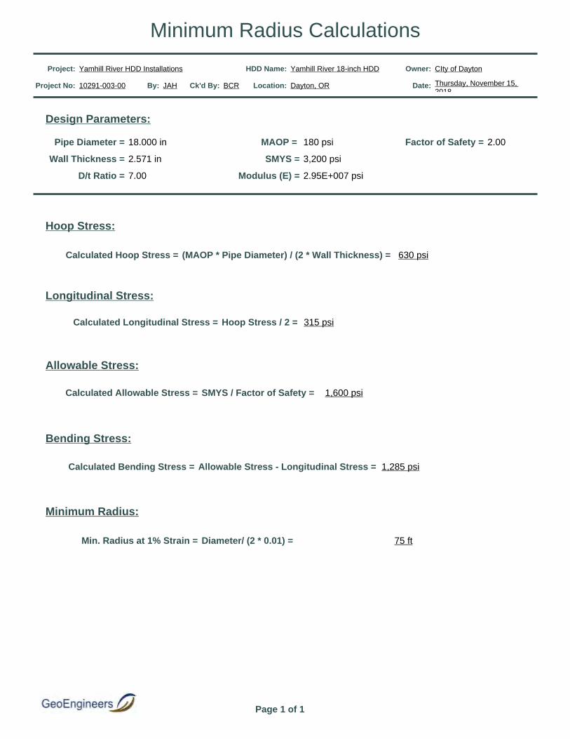
Pipe Diameter = 18.000 in MAOP = 180 psi Factor of Safety = 2.00
Wall Thickness = 2.571 in SMYS = 3,200 psi
D/t Ratio = 7.00 Modulus (E) = 2.95E+007 psi
Design Parameters:
Hoop Stress:
Calculated Hoop Stress = (MAOP * Pipe Diameter) / (2 * Wall Thickness) = 630 psi
Longitudinal Stress:
Calculated Longitudinal Stress = Hoop Stress / 2 = 315 psi
Allowable Stress:
Calculated Allowable Stress = SMYS / Factor of Safety = 1,600 psi
Bending Stress:
Calculated Bending Stress = Allowable Stress - Longitudinal Stress = 1,285 psi
Minimum Radius:
Min. Radius at 1% Strain = Diameter/ (2 * 0.01) = 75 ft
Project: Yamhill River HDD Installations HDD Name: Yamhill River 18-inch HDD Owner: CIty of Dayton
Project No: 10291-003-00 By: JAH Ck'd By: BCR Location: Dayton, OR Date: Thursday, November 15, 2018
Page 1 of 1
Minimum Radius Calculations

Project Name: Yamhill River HDD Installations HDD Name: Yamhill River 18-inch HDD Owner CIty of Dayton
Project No: 10291-003-00 By: JAH Ck'd By: BCR Location: Dayton, OR Date: Thursday, November 15, 2018
Design Parameters
Pipe diameter = 18.000 in HDS = 1,000 psi
Wall Thickness = 2.571 in Pressure Rating = 333 psi
SDR = 7.00 Soil Unit Weight = 118.00 lb/ft³
Yield Stress = 3,200 psi Soil Friction Angle = 0.00 Degrees
Operating Pressure = 180 psi Maximum Depth = 85.00 ft
Minimum Radius of Curvature = 400 ft Arching Factor = 1.00 ft
Coefficient of Thermal Expansion = 8E-05 in/in/°F Groundwater Elevation = 65.00 ft
Assumed Installation Temperature = 73 °F Groundwater Head = 65.00 ft
Assumed Operating Temperature = 73 °F
Case - Tie-in - Empty
Elastic Modulus = 40,000 psi Total Ring Deflection = 3.41 %
Earth Pressure = -41.49 psi Ovality Factor = 0.74
External Pressure = -69.65 psi TDR = 0.99
Internal Pressure = 0.00 psi Wall Stress = -243.83 psi
Net Pressure = -69.65 psi Collapse Pressure = -342.32 psi
Buoyant Deflection = 0.05 % Wall Stress FOS = 4.10
Earth Deflection = 3.36 % Collapse FOS = 4.91
Case - Tie-in - Full
Elastic Modulus = 40,000 psi Total Ring Deflection = 2.34 %
Earth Pressure = -28.83 psi Ovality Factor = 0.83
External Pressure = -69.65 psi TDR = 0.99
Internal Pressure = 40.82 psi Wall Stress = -121.34 psi
Net Pressure = -28.83 psi Collapse Pressure = -380.90 psi
Buoyant Deflection = 0.00 % Wall Stress FOS = 8.24
Earth Deflection = 2.34 % Collapse FOS = 13.21
Page 1 of 3
Pipe Collapse Checks

Case - Operating Conditions
Elastic Modulus = 29,000 psi Total Ring Deflection = 0.00 %
Earth Pressure = -28.83 psi Ovality Factor = 1.00
External Pressure = -69.65 psi TDR = 0.99
Internal Pressure = 220.82 psi Wall Stress = 418.76 psi
Net Pressure = 151.17 psi Collapse Pressure = -334.05 psi
Buoyant Deflection = 0.00 % Wall Stress FOS = 2.39
Earth Deflection = 3.22 % Rupture FOS = 2.20
Case - Maintainance Conditions - Depressurized and Empty
Elastic Modulus = 29,000 psi Total Ring Deflection = 4.71 %
Earth Pressure = -41.49 psi Ovality Factor = 0.64
External Pressure = -69.65 psi TDR = 0.99
Internal Pressure = 0.00 psi Wall Stress = -243.83 psi
Net Pressure = -69.65 psi Collapse Pressure = -215.30 psi
Buoyant Deflection = 0.07 % Wall Stress FOS = 4.10
Earth Deflection = 4.64 % Collapse FOS = 3.09
Case - Maintainance Conditions - Depressurized and Full
Elastic Modulus = 29,000 psi Total Ring Deflection = 3.22 %
Earth Pressure = -28.83 psi Ovality Factor = 0.76
External Pressure = -69.65 psi TDR = 0.99
Internal Pressure = 40.82 psi Wall Stress = -121.34 psi
Net Pressure = -28.83 psi Collapse Pressure = -253.07 psi
Buoyant Deflection = 0.00 % Wall Stress FOS = 8.24
Earth Deflection = 3.22 % Collapse FOS = 8.78
Page 2 of 3
Pipe Collapse Checks

Project Name: Yamhill River HDD Installations HDD Name: Yamhill River 18-inch HDD Owner: Westech Engineering
Project No: 10291-003-00 By: JAH Ck'd By: BCR Location: Dayton, OR Date: Thursday, November 15, 2018
Page 3 of 3
Pipe Collapse Checks

Project: Yamhill River HDD Installations HDD Name: Yamhill River 18-inch HDD Owner: CIty of Dayton
Project No: 10291-003-00 By: JAH Ck'd By: BCR Location: Dayton, OR Date: Thursday, November 15, 2018
Installation Case:9.50 lb/gal Drilling Fluid With the Pipe Annulus Full
Segment Parameters
Segment Name = Entry Tangent
Segment Type = Straight
Segment Length = 390.02 ft
Radius of Curvature = 0 ft
Angle Turned = 0.00 deg
Center Displacement = 0.00 ft
Segment Force Componets
Normal Force = 0 lb
Drag Force = 13,233 lb
Friction Force = 2,061 lb
Segment Weight = 1,461 lb
Tension = 0 lb
Average Tension = 0 lb
Segment Force = 16,755 lb
Cumulative Force = 16,755 lb
Segment Installation Stress Checks
Stress Component Calculated Allowable PE Pipe Stress Checks
Segment Axial Stress = 134 psi Ring Deflection = 1.09 %
Cumulative Axial Stress = 134 psi 1,007 psi Wall Stress = -120.33 psi
External Pressure = -47.96 psi Wall Stress FOS = 8.31
Internal Pressure = 15.85 psi Collapse Pressure = -591.05 psi
Net Pressure = -32.11 psi Net External Pressure = -32.11 psi
Collapse FOS = 18.41
Reversed Installation:9.50 lb/gal Drilling Fluid With the Pipe Annulus Full Segment 1 of 7
Product Pipe Parameters
Pipe Diameter = 18.000 in
Wall Thickness = 2.571 in
Yield Stress = 3,200 psi
Young's Modulus = 2.20E+004 psi
Total Pipe Length = 1,144 ft
Moment of Inertia = 3,811 in⁴
Pipe Face Area = 124.62 in²
D/t Ratio = 7.00
Poisson Ratio = 0.45
Coefficient of Soil Friction = 0.30
Fluid Drag Coefficient = 0.05
Effective Weight Calculations
Total Empty Pipe Weight In Air= 51.30 lb/ft
Pipe Interior Volume = 0.90 ft³/ft
Coating Thickness = 0.00 in
Coating Density = 0.00 lb/ft³
Pipe Exterior Volume = 1.77 ft³/ft
Displaced Fluid Weight = 125.58 lb/ft
B.C. Lines Weight = 0.00 lb/ft
B.C. Lines Volume = 0.00 ft³/ft
Unit Weight of B.C. Fluid = 62.40 lb/ft³
Effective Weight of Pipe = -18.01 lb/ft
1 of 12
Installation Load Calculations

Segment Parameters
Segment Name = Vertical Curve 1
Segment Type = Vertical Curve
Segment Length = 125.66 ft
Radius of Curvature = 600 ft
Angle Turned = 12.00 deg
Center Displacement = 3.29 ft
Segment Force Componets
Normal Force = 3,512 lb
Drag Force = 4,264 lb
Friction Force = 1,054 lb
Segment Weight = 237 lb
Tension = 23,363 lb
Average Tension = 20,059 lb
Segment Force = 6,608 lb
Cumulative Force = 23,363 lb
Segment Installation Stress Checks
Stress Component Calculated Allowable PE Pipe Stress Checks
Segment Axial Stress = 53 psi Ring Deflection = 1.80 %
Cumulative Axial Stress = 187 psi 956 psi Wall Stress = -183.95 psi
External Pressure = -79.42 psi Wall Stress FOS = 5.44
Internal Pressure = 31.35 psi Collapse Pressure = -531.88 psi
Net Pressure = -48.07 psi Net External Pressure = -48.07 psi
Collapse FOS = 11.06
Reversed Installation:9.50 lb/gal Drilling Fluid With the Pipe Annulus Full Segment 2 of 7
Segment Parameters
Segment Name = Tangent 2
Segment Type = Straight
Segment Length = 91.45 ft
Radius of Curvature = 0 ft
Angle Turned = 0.00 deg
Center Displacement = 0.00 ft
Segment Force Componets
Normal Force = 0 lb
Drag Force = 3,103 lb
Friction Force = 494 lb
Segment Weight = 0 lb
Tension = 0 lb
Average Tension = 0 lb
Segment Force = 3,597 lb
Cumulative Force = 26,960 lb
Segment Installation Stress Checks
Stress Component Calculated Allowable PE Pipe Stress Checks
Segment Axial Stress = 29 psi Ring Deflection = 1.88 %
Cumulative Axial Stress = 216 psi 1,003 psi Wall Stress = -191.12 psi
External Pressure = -82.97 psi Wall Stress FOS = 5.23
Internal Pressure = 33.10 psi Collapse Pressure = -541.15 psi
Net Pressure = -49.87 psi Net External Pressure = -49.87 psi
Collapse FOS = 10.85
Reversed Installation:9.50 lb/gal Drilling Fluid With the Pipe Annulus Full Segment 3 of 7
2 of 12
Installation Load Calculations
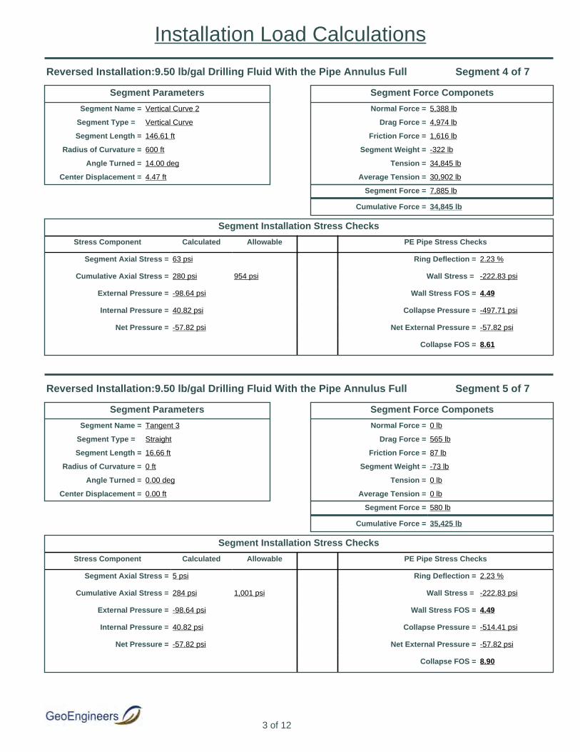
Segment Parameters
Segment Name = Vertical Curve 2
Segment Type = Vertical Curve
Segment Length = 146.61 ft
Radius of Curvature = 600 ft
Angle Turned = 14.00 deg
Center Displacement = 4.47 ft
Segment Force Componets
Normal Force = 5,388 lb
Drag Force = 4,974 lb
Friction Force = 1,616 lb
Segment Weight = -322 lb
Tension = 34,845 lb
Average Tension = 30,902 lb
Segment Force = 7,885 lb
Cumulative Force = 34,845 lb
Segment Installation Stress Checks
Stress Component Calculated Allowable PE Pipe Stress Checks
Segment Axial Stress = 63 psi Ring Deflection = 2.23 %
Cumulative Axial Stress = 280 psi 954 psi Wall Stress = -222.83 psi
External Pressure = -98.64 psi Wall Stress FOS = 4.49
Internal Pressure = 40.82 psi Collapse Pressure = -497.71 psi
Net Pressure = -57.82 psi Net External Pressure = -57.82 psi
Collapse FOS = 8.61
Reversed Installation:9.50 lb/gal Drilling Fluid With the Pipe Annulus Full Segment 4 of 7
Segment Parameters
Segment Name = Tangent 3
Segment Type = Straight
Segment Length = 16.66 ft
Radius of Curvature = 0 ft
Angle Turned = 0.00 deg
Center Displacement = 0.00 ft
Segment Force Componets
Normal Force = 0 lb
Drag Force = 565 lb
Friction Force = 87 lb
Segment Weight = -73 lb
Tension = 0 lb
Average Tension = 0 lb
Segment Force = 580 lb
Cumulative Force = 35,425 lb
Segment Installation Stress Checks
Stress Component Calculated Allowable PE Pipe Stress Checks
Segment Axial Stress = 5 psi Ring Deflection = 2.23 %
Cumulative Axial Stress = 284 psi 1,001 psi Wall Stress = -222.83 psi
External Pressure = -98.64 psi Wall Stress FOS = 4.49
Internal Pressure = 40.82 psi Collapse Pressure = -514.41 psi
Net Pressure = -57.82 psi Net External Pressure = -57.82 psi
Collapse FOS = 8.90
Reversed Installation:9.50 lb/gal Drilling Fluid With the Pipe Annulus Full Segment 5 of 7
3 of 12
Installation Load Calculations

Segment Parameters
Segment Name = Horizontal Curve 1
Segment Type = Horizontal Curve
Segment Length = 147.85 ft
Radius of Curvature = 600 ft
Angle Turned = 13.70 deg
Center Displacement = 4.28 ft
Segment Force Componets
Normal Force = 6,224 lb
Drag Force = 5,016 lb
Friction Force = 1,867 lb
Segment Weight = -331 lb
Tension = 43,844 lb
Average Tension = 39,634 lb
Segment Force = 8,419 lb
Cumulative Force = 43,844 lb
Segment Installation Stress Checks
Stress Component Calculated Allowable PE Pipe Stress Checks
Segment Axial Stress = 68 psi Ring Deflection = 2.23 %
Cumulative Axial Stress = 352 psi 954 psi Wall Stress = -222.83 psi
External Pressure = -98.64 psi Wall Stress FOS = 4.49
Internal Pressure = 40.82 psi Collapse Pressure = -486.60 psi
Net Pressure = -57.82 psi Net External Pressure = -57.82 psi
Collapse FOS = 8.42
Reversed Installation:9.50 lb/gal Drilling Fluid With the Pipe Annulus Full Segment 6 of 7
Segment Parameters
Segment Name = Exit Tangent
Segment Type = Straight
Segment Length = 225.38 ft
Radius of Curvature = 0 ft
Angle Turned = 0.00 deg
Center Displacement = 0.00 ft
Segment Force Componets
Normal Force = 0 lb
Drag Force = 7,647 lb
Friction Force = 1,182 lb
Segment Weight = -982 lb
Tension = 0 lb
Average Tension = 0 lb
Segment Force = 7,846 lb
Cumulative Force = 51,690 lb
Segment Installation Stress Checks
Stress Component Calculated Allowable PE Pipe Stress Checks
Segment Axial Stress = 63 psi Ring Deflection = 1.97 %
Cumulative Axial Stress = 415 psi 1,003 psi Wall Stress = -199.50 psi
External Pressure = -87.11 psi Wall Stress FOS = 5.01
Internal Pressure = 35.14 psi Collapse Pressure = -507.08 psi
Net Pressure = -51.97 psi Net External Pressure = -51.97 psi
Collapse FOS = 9.76
Reversed Installation:9.50 lb/gal Drilling Fluid With the Pipe Annulus Full Segment 7 of 7
4 of 12
Installation Load Calculations

Installation Case:10.50 lb/gal Drilling Fluid With the Pipe Annulus Full
Segment Parameters
Segment Name = Entry Tangent
Segment Type = Straight
Segment Length = 390.02 ft
Radius of Curvature = 0 ft
Angle Turned = 0.00 deg
Center Displacement = 0.00 ft
Segment Force Componets
Normal Force = 0 lb
Drag Force = 13,233 lb
Friction Force = 3,574 lb
Segment Weight = 2,533 lb
Tension = 0 lb
Average Tension = 0 lb
Segment Force = 19,340 lb
Cumulative Force = 19,340 lb
Segment Installation Stress Checks
Stress Component Calculated Allowable PE Pipe Stress Checks
Segment Axial Stress = 155 psi Ring Deflection = 1.09 %
Cumulative Axial Stress = 155 psi 1,002 psi Wall Stress = -130.24 psi
External Pressure = -50.79 psi Wall Stress FOS = 7.68
Internal Pressure = 15.85 psi Collapse Pressure = -587.81 psi
Net Pressure = -34.94 psi Net External Pressure = -34.94 psi
Collapse FOS = 16.82
Reversed Installation:10.50 lb/gal Drilling Fluid With the Pipe Annulus Full Segment 1 of 7
Product Pipe Parameters
Pipe Diameter = 18.000 in
Wall Thickness = 2.571 in
Yield Stress = 3,200 psi
Young's Modulus = 2.20E+004 psi
Total Pipe Length = 1,144 ft
Moment of Inertia = 3,811 in⁴
Pipe Face Area = 124.62 in²
D/t Ratio = 7.00
Poisson Ratio = 0.45
Coefficient of Soil Friction = 0.30
Fluid Drag Coefficient = 0.05
Effective Weight Calculations
Total Empty Pipe Weight In Air= 51.30 lb/ft
Pipe Interior Volume = 0.90 ft³/ft
Coating Thickness = 0.00 in
Coating Density = 0.00 lb/ft³
Pipe Exterior Volume = 1.77 ft³/ft
Displaced Fluid Weight = 138.80 lb/ft
B.C. Lines Weight = 0.00 lb/ft
B.C. Lines Volume = 0.00 ft³/ft
Unit Weight of B.C. Fluid = 62.40 lb/ft³
Effective Weight of Pipe = -31.23 lb/ft
5 of 12
Installation Load Calculations
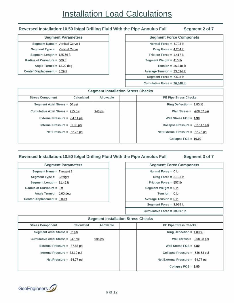
Segment Parameters
Segment Name = Vertical Curve 1
Segment Type = Vertical Curve
Segment Length = 125.66 ft
Radius of Curvature = 600 ft
Angle Turned = 12.00 deg
Center Displacement = 3.29 ft
Segment Force Componets
Normal Force = 4,723 lb
Drag Force = 4,264 lb
Friction Force = 1,417 lb
Segment Weight = 410 lb
Tension = 26,848 lb
Average Tension = 23,094 lb
Segment Force = 7,508 lb
Cumulative Force = 26,848 lb
Segment Installation Stress Checks
Stress Component Calculated Allowable PE Pipe Stress Checks
Segment Axial Stress = 60 psi Ring Deflection = 1.80 %
Cumulative Axial Stress = 215 psi 948 psi Wall Stress = -200.37 psi
External Pressure = -84.11 psi Wall Stress FOS = 4.99
Internal Pressure = 31.35 psi Collapse Pressure = -527.47 psi
Net Pressure = -52.76 psi Net External Pressure = -52.76 psi
Collapse FOS = 10.00
Reversed Installation:10.50 lb/gal Drilling Fluid With the Pipe Annulus Full Segment 2 of 7
Segment Parameters
Segment Name = Tangent 2
Segment Type = Straight
Segment Length = 91.45 ft
Radius of Curvature = 0 ft
Angle Turned = 0.00 deg
Center Displacement = 0.00 ft
Segment Force Componets
Normal Force = 0 lb
Drag Force = 3,103 lb
Friction Force = 857 lb
Segment Weight = 0 lb
Tension = 0 lb
Average Tension = 0 lb
Segment Force = 3,959 lb
Cumulative Force = 30,807 lb
Segment Installation Stress Checks
Stress Component Calculated Allowable PE Pipe Stress Checks
Segment Axial Stress = 32 psi Ring Deflection = 1.88 %
Cumulative Axial Stress = 247 psi 995 psi Wall Stress = -208.28 psi
External Pressure = -87.87 psi Wall Stress FOS = 4.80
Internal Pressure = 33.10 psi Collapse Pressure = -536.53 psi
Net Pressure = -54.77 psi Net External Pressure = -54.77 psi
Collapse FOS = 9.80
Reversed Installation:10.50 lb/gal Drilling Fluid With the Pipe Annulus Full Segment 3 of 7
6 of 12
Installation Load Calculations

Segment Parameters
Segment Name = Vertical Curve 2
Segment Type = Vertical Curve
Segment Length = 146.61 ft
Radius of Curvature = 600 ft
Angle Turned = 14.00 deg
Center Displacement = 4.47 ft
Segment Force Componets
Normal Force = 6,921 lb
Drag Force = 4,974 lb
Friction Force = 2,076 lb
Segment Weight = -558 lb
Tension = 39,376 lb
Average Tension = 35,091 lb
Segment Force = 8,569 lb
Cumulative Force = 39,376 lb
Segment Installation Stress Checks
Stress Component Calculated Allowable PE Pipe Stress Checks
Segment Axial Stress = 69 psi Ring Deflection = 2.24 %
Cumulative Axial Stress = 316 psi 944 psi Wall Stress = -243.22 psi
External Pressure = -104.47 psi Wall Stress FOS = 4.11
Internal Pressure = 40.82 psi Collapse Pressure = -491.99 psi
Net Pressure = -63.65 psi Net External Pressure = -63.65 psi
Collapse FOS = 7.73
Reversed Installation:10.50 lb/gal Drilling Fluid With the Pipe Annulus Full Segment 4 of 7
Segment Parameters
Segment Name = Tangent 3
Segment Type = Straight
Segment Length = 16.66 ft
Radius of Curvature = 0 ft
Angle Turned = 0.00 deg
Center Displacement = 0.00 ft
Segment Force Componets
Normal Force = 0 lb
Drag Force = 565 lb
Friction Force = 151 lb
Segment Weight = -126 lb
Tension = 0 lb
Average Tension = 0 lb
Segment Force = 591 lb
Cumulative Force = 39,967 lb
Segment Installation Stress Checks
Stress Component Calculated Allowable PE Pipe Stress Checks
Segment Axial Stress = 5 psi Ring Deflection = 2.24 %
Cumulative Axial Stress = 321 psi 991 psi Wall Stress = -243.22 psi
External Pressure = -104.47 psi Wall Stress FOS = 4.11
Internal Pressure = 40.82 psi Collapse Pressure = -508.97 psi
Net Pressure = -63.65 psi Net External Pressure = -63.65 psi
Collapse FOS = 8.00
Reversed Installation:10.50 lb/gal Drilling Fluid With the Pipe Annulus Full Segment 5 of 7
7 of 12
Installation Load Calculations

Segment Parameters
Segment Name = Horizontal Curve 1
Segment Type = Horizontal Curve
Segment Length = 147.85 ft
Radius of Curvature = 600 ft
Angle Turned = 13.70 deg
Center Displacement = 4.28 ft
Segment Force Componets
Normal Force = 7,816 lb
Drag Force = 5,016 lb
Friction Force = 2,345 lb
Segment Weight = -575 lb
Tension = 49,098 lb
Average Tension = 44,532 lb
Segment Force = 9,131 lb
Cumulative Force = 49,098 lb
Segment Installation Stress Checks
Stress Component Calculated Allowable PE Pipe Stress Checks
Segment Axial Stress = 73 psi Ring Deflection = 2.24 %
Cumulative Axial Stress = 394 psi 944 psi Wall Stress = -243.22 psi
External Pressure = -104.47 psi Wall Stress FOS = 4.11
Internal Pressure = 40.82 psi Collapse Pressure = -479.77 psi
Net Pressure = -63.65 psi Net External Pressure = -63.65 psi
Collapse FOS = 7.54
Reversed Installation:10.50 lb/gal Drilling Fluid With the Pipe Annulus Full Segment 6 of 7
Segment Parameters
Segment Name = Exit Tangent
Segment Type = Straight
Segment Length = 225.38 ft
Radius of Curvature = 0 ft
Angle Turned = 0.00 deg
Center Displacement = 0.00 ft
Segment Force Componets
Normal Force = 0 lb
Drag Force = 7,647 lb
Friction Force = 2,049 lb
Segment Weight = -1,703 lb
Tension = 0 lb
Average Tension = 0 lb
Segment Force = 7,993 lb
Cumulative Force = 57,091 lb
Segment Installation Stress Checks
Stress Component Calculated Allowable PE Pipe Stress Checks
Segment Axial Stress = 64 psi Ring Deflection = 1.98 %
Cumulative Axial Stress = 458 psi 994 psi Wall Stress = -217.51 psi
External Pressure = -92.26 psi Wall Stress FOS = 4.60
Internal Pressure = 35.14 psi Collapse Pressure = -500.07 psi
Net Pressure = -57.12 psi Net External Pressure = -57.12 psi
Collapse FOS = 8.76
Reversed Installation:10.50 lb/gal Drilling Fluid With the Pipe Annulus Full Segment 7 of 7
8 of 12
Installation Load Calculations
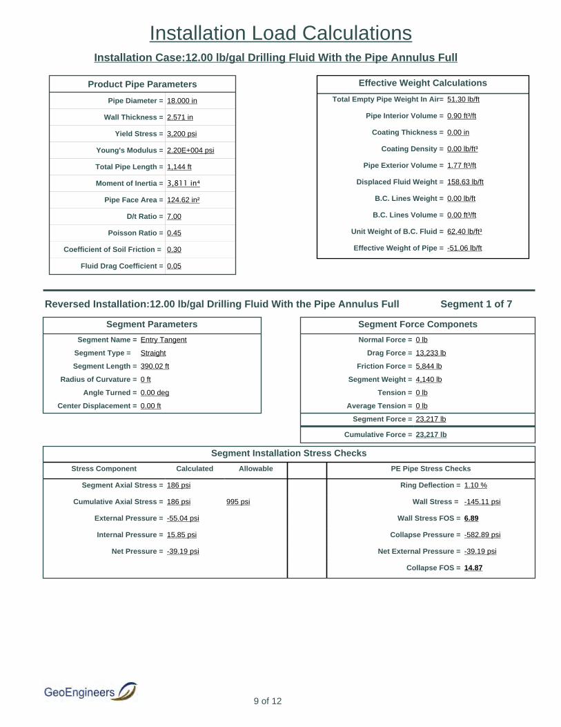
Installation Case:12.00 lb/gal Drilling Fluid With the Pipe Annulus Full
Segment Parameters
Segment Name = Entry Tangent
Segment Type = Straight
Segment Length = 390.02 ft
Radius of Curvature = 0 ft
Angle Turned = 0.00 deg
Center Displacement = 0.00 ft
Segment Force Componets
Normal Force = 0 lb
Drag Force = 13,233 lb
Friction Force = 5,844 lb
Segment Weight = 4,140 lb
Tension = 0 lb
Average Tension = 0 lb
Segment Force = 23,217 lb
Cumulative Force = 23,217 lb
Segment Installation Stress Checks
Stress Component Calculated Allowable PE Pipe Stress Checks
Segment Axial Stress = 186 psi Ring Deflection = 1.10 %
Cumulative Axial Stress = 186 psi 995 psi Wall Stress = -145.11 psi
External Pressure = -55.04 psi Wall Stress FOS = 6.89
Internal Pressure = 15.85 psi Collapse Pressure = -582.89 psi
Net Pressure = -39.19 psi Net External Pressure = -39.19 psi
Collapse FOS = 14.87
Reversed Installation:12.00 lb/gal Drilling Fluid With the Pipe Annulus Full Segment 1 of 7
Product Pipe Parameters
Pipe Diameter = 18.000 in
Wall Thickness = 2.571 in
Yield Stress = 3,200 psi
Young's Modulus = 2.20E+004 psi
Total Pipe Length = 1,144 ft
Moment of Inertia = 3,811 in⁴
Pipe Face Area = 124.62 in²
D/t Ratio = 7.00
Poisson Ratio = 0.45
Coefficient of Soil Friction = 0.30
Fluid Drag Coefficient = 0.05
Effective Weight Calculations
Total Empty Pipe Weight In Air= 51.30 lb/ft
Pipe Interior Volume = 0.90 ft³/ft
Coating Thickness = 0.00 in
Coating Density = 0.00 lb/ft³
Pipe Exterior Volume = 1.77 ft³/ft
Displaced Fluid Weight = 158.63 lb/ft
B.C. Lines Weight = 0.00 lb/ft
B.C. Lines Volume = 0.00 ft³/ft
Unit Weight of B.C. Fluid = 62.40 lb/ft³
Effective Weight of Pipe = -51.06 lb/ft
9 of 12
Installation Load Calculations

Segment Parameters
Segment Name = Vertical Curve 1
Segment Type = Vertical Curve
Segment Length = 125.66 ft
Radius of Curvature = 600 ft
Angle Turned = 12.00 deg
Center Displacement = 3.29 ft
Segment Force Componets
Normal Force = 6,527 lb
Drag Force = 4,264 lb
Friction Force = 1,958 lb
Segment Weight = 671 lb
Tension = 32,068 lb
Average Tension = 27,642 lb
Segment Force = 8,851 lb
Cumulative Force = 32,068 lb
Segment Installation Stress Checks
Stress Component Calculated Allowable PE Pipe Stress Checks
Segment Axial Stress = 71 psi Ring Deflection = 1.81 %
Cumulative Axial Stress = 257 psi 935 psi Wall Stress = -225.00 psi
External Pressure = -91.15 psi Wall Stress FOS = 4.44
Internal Pressure = 31.35 psi Collapse Pressure = -520.76 psi
Net Pressure = -59.80 psi Net External Pressure = -59.80 psi
Collapse FOS = 8.71
Reversed Installation:12.00 lb/gal Drilling Fluid With the Pipe Annulus Full Segment 2 of 7
Segment Parameters
Segment Name = Tangent 2
Segment Type = Straight
Segment Length = 91.45 ft
Radius of Curvature = 0 ft
Angle Turned = 0.00 deg
Center Displacement = 0.00 ft
Segment Force Componets
Normal Force = 0 lb
Drag Force = 3,103 lb
Friction Force = 1,401 lb
Segment Weight = 0 lb
Tension = 0 lb
Average Tension = 0 lb
Segment Force = 4,503 lb
Cumulative Force = 36,571 lb
Segment Installation Stress Checks
Stress Component Calculated Allowable PE Pipe Stress Checks
Segment Axial Stress = 36 psi Ring Deflection = 1.89 %
Cumulative Axial Stress = 293 psi 981 psi Wall Stress = -234.01 psi
External Pressure = -95.22 psi Wall Stress FOS = 4.27
Internal Pressure = 33.10 psi Collapse Pressure = -529.47 psi
Net Pressure = -62.12 psi Net External Pressure = -62.12 psi
Collapse FOS = 8.52
Reversed Installation:12.00 lb/gal Drilling Fluid With the Pipe Annulus Full Segment 3 of 7
10 of 12
Installation Load Calculations

Segment Parameters
Segment Name = Vertical Curve 2
Segment Type = Vertical Curve
Segment Length = 146.61 ft
Radius of Curvature = 600 ft
Angle Turned = 14.00 deg
Center Displacement = 4.47 ft
Segment Force Componets
Normal Force = 9,209 lb
Drag Force = 4,974 lb
Friction Force = 2,763 lb
Segment Weight = -912 lb
Tension = 46,159 lb
Average Tension = 41,365 lb
Segment Force = 9,588 lb
Cumulative Force = 46,159 lb
Segment Installation Stress Checks
Stress Component Calculated Allowable PE Pipe Stress Checks
Segment Axial Stress = 77 psi Ring Deflection = 2.24 %
Cumulative Axial Stress = 370 psi 927 psi Wall Stress = -273.81 psi
External Pressure = -113.21 psi Wall Stress FOS = 3.65
Internal Pressure = 40.82 psi Collapse Pressure = -483.26 psi
Net Pressure = -72.39 psi Net External Pressure = -72.39 psi
Collapse FOS = 6.68
Reversed Installation:12.00 lb/gal Drilling Fluid With the Pipe Annulus Full Segment 4 of 7
Segment Parameters
Segment Name = Tangent 3
Segment Type = Straight
Segment Length = 16.66 ft
Radius of Curvature = 0 ft
Angle Turned = 0.00 deg
Center Displacement = 0.00 ft
Segment Force Componets
Normal Force = 0 lb
Drag Force = 565 lb
Friction Force = 248 lb
Segment Weight = -206 lb
Tension = 0 lb
Average Tension = 0 lb
Segment Force = 607 lb
Cumulative Force = 46,766 lb
Segment Installation Stress Checks
Stress Component Calculated Allowable PE Pipe Stress Checks
Segment Axial Stress = 5 psi Ring Deflection = 2.24 %
Cumulative Axial Stress = 375 psi 975 psi Wall Stress = -273.81 psi
External Pressure = -113.21 psi Wall Stress FOS = 3.65
Internal Pressure = 40.82 psi Collapse Pressure = -500.66 psi
Net Pressure = -72.39 psi Net External Pressure = -72.39 psi
Collapse FOS = 6.92
Reversed Installation:12.00 lb/gal Drilling Fluid With the Pipe Annulus Full Segment 5 of 7
11 of 12
Installation Load Calculations

Segment Parameters
Segment Name = Horizontal Curve 1
Segment Type = Horizontal Curve
Segment Length = 147.85 ft
Radius of Curvature = 600 ft
Angle Turned = 13.70 deg
Center Displacement = 4.28 ft
Segment Force Componets
Normal Force = 10,194 lb
Drag Force = 5,016 lb
Friction Force = 3,058 lb
Segment Weight = -940 lb
Tension = 56,959 lb
Average Tension = 51,862 lb
Segment Force = 10,193 lb
Cumulative Force = 56,959 lb
Segment Installation Stress Checks
Stress Component Calculated Allowable PE Pipe Stress Checks
Segment Axial Stress = 82 psi Ring Deflection = 2.24 %
Cumulative Axial Stress = 457 psi 927 psi Wall Stress = -273.81 psi
External Pressure = -113.21 psi Wall Stress FOS = 3.65
Internal Pressure = 40.82 psi Collapse Pressure = -469.30 psi
Net Pressure = -72.39 psi Net External Pressure = -72.39 psi
Collapse FOS = 6.48
Reversed Installation:12.00 lb/gal Drilling Fluid With the Pipe Annulus Full Segment 6 of 7
Segment Parameters
Segment Name = Exit Tangent
Segment Type = Straight
Segment Length = 225.38 ft
Radius of Curvature = 0 ft
Angle Turned = 0.00 deg
Center Displacement = 0.00 ft
Segment Force Componets
Normal Force = 0 lb
Drag Force = 7,647 lb
Friction Force = 3,350 lb
Segment Weight = -2,784 lb
Tension = 0 lb
Average Tension = 0 lb
Segment Force = 8,213 lb
Cumulative Force = 65,172 lb
Segment Installation Stress Checks
Stress Component Calculated Allowable PE Pipe Stress Checks
Segment Axial Stress = 66 psi Ring Deflection = 1.98 %
Cumulative Axial Stress = 523 psi 979 psi Wall Stress = -244.53 psi
External Pressure = -99.97 psi Wall Stress FOS = 4.09
Internal Pressure = 35.14 psi Collapse Pressure = -489.33 psi
Net Pressure = -64.83 psi Net External Pressure = -64.83 psi
Collapse FOS = 7.55
Reversed Installation:12.00 lb/gal Drilling Fluid With the Pipe Annulus Full Segment 7 of 7
12 of 12
Installation Load Calculations
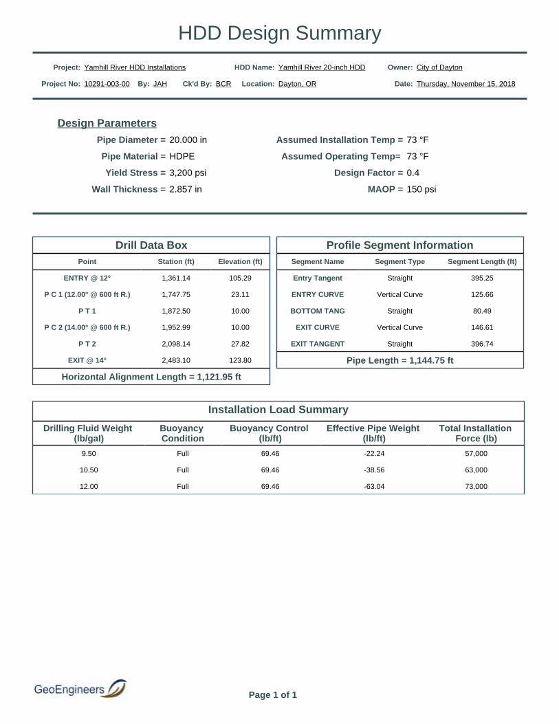
Drill Data BoxPoint Station (ft) Elevation (ft)
ENTRY @ 12° 1,361.14 105.29
P C 1 (12.00° @ 600 ft R.) 1,747.75 23.11
P T 1 1,872.50 10.00
P C 2 (14.00° @ 600 ft R.) 1,952.99 10.00
P T 2 2,098.14 27.82
EXIT @ 14° 2,483.10 123.80
Horizontal Alignment Length = 1,121.95 ft
Design ParametersPipe Diameter = 20.000 in Assumed Installation Temp = 73 °F
Pipe Material = HDPE Assumed Operating Temp= 73 °F
Yield Stress = 3,200 psi Design Factor = 0.4
Wall Thickness = 2.857 in MAOP = 150 psi
Profile Segment InformationSegment Name Segment Type Segment Length (ft)
Entry Tangent Straight 395.25
ENTRY CURVE Vertical Curve 125.66
BOTTOM TANG Straight 80.49
EXIT CURVE Vertical Curve 146.61
EXIT TANGENT Straight 396.74
Pipe Length = 1,144.75 ft
Installation Load Summary
Drilling Fluid Weight (lb/gal)
Buoyancy Condition
Buoyancy Control (lb/ft)
Effective Pipe Weight (lb/ft)
Total Installation Force (lb)
9.50 Full 69.46 -22.24 57,000
10.50 Full 69.46 -38.56 63,000
12.00 Full 69.46 -63.04 73,000
Project: Yamhill River HDD Installations HDD Name: Yamhill River 20-inch HDD Owner: City of Dayton
Project No: 10291-003-00 By: JAH Ck'd By: BCR Location: Dayton, OR Date: Thursday, November 15, 2018
Page 1 of 1
HDD Design Summary

Pipe Diameter = 20.000 in MAOP = 150 psi Factor of Safety = 2.00
Wall Thickness = 2.857 in SMYS = 3,200 psi
D/t Ratio = 7.00 Modulus (E) = 2.95E+007 psi
Design Parameters:
Hoop Stress:
Calculated Hoop Stress = (MAOP * Pipe Diameter) / (2 * Wall Thickness) = 525 psi
Longitudinal Stress:
Calculated Longitudinal Stress = Hoop Stress / 2 = 263 psi
Allowable Stress:
Calculated Allowable Stress = SMYS / Factor of Safety = 1,600 psi
Bending Stress:
Calculated Bending Stress = Allowable Stress - Longitudinal Stress = 1,337 psi
Minimum Radius:
Min. Radius at 1% Strain = Diameter/ (2 * 0.01) = 83 ft
Project: Yamhill River HDD Installations HDD Name: Yamhill River 20-inch HDD Owner: City of Dayton
Project No: 10291-003-00 By: JAH Ck'd By: BCR Location: Dayton, OR Date: Thursday, November 15, 2018
Page 1 of 1
Minimum Radius Calculations
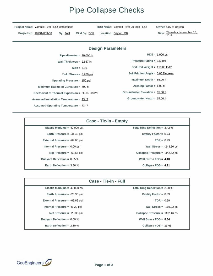
Project Name: Yamhill River HDD Installations HDD Name: Yamhill River 20-inch HDD Owner City of Dayton
Project No: 10291-003-00 By: JAH Ck'd By: BCR Location: Dayton, OR Date: Thursday, November 15, 2018
Design Parameters
Pipe diameter = 20.000 in HDS = 1,000 psi
Wall Thickness = 2.857 in Pressure Rating = 333 psi
SDR = 7.00 Soil Unit Weight = 118.00 lb/ft³
Yield Stress = 3,200 psi Soil Friction Angle = 0.00 Degrees
Operating Pressure = 150 psi Maximum Depth = 85.00 ft
Minimum Radius of Curvature = 400 ft Arching Factor = 1.00 ft
Coefficient of Thermal Expansion = 8E-05 in/in/°F Groundwater Elevation = 65.00 ft
Assumed Installation Temperature = 73 °F Groundwater Head = 65.00 ft
Assumed Operating Temperature = 73 °F
Case - Tie-in - Empty
Elastic Modulus = 40,000 psi Total Ring Deflection = 3.42 %
Earth Pressure = -41.49 psi Ovality Factor = 0.74
External Pressure = -69.65 psi TDR = 0.99
Internal Pressure = 0.00 psi Wall Stress = -243.80 psi
Net Pressure = -69.65 psi Collapse Pressure = -342.32 psi
Buoyant Deflection = 0.05 % Wall Stress FOS = 4.10
Earth Deflection = 3.36 % Collapse FOS = 4.91
Case - Tie-in - Full
Elastic Modulus = 40,000 psi Total Ring Deflection = 2.30 %
Earth Pressure = -28.36 psi Ovality Factor = 0.83
External Pressure = -69.65 psi TDR = 0.99
Internal Pressure = 41.29 psi Wall Stress = -119.92 psi
Net Pressure = -28.36 psi Collapse Pressure = -382.46 psi
Buoyant Deflection = 0.00 % Wall Stress FOS = 8.34
Earth Deflection = 2.30 % Collapse FOS = 13.49
Page 1 of 3
Pipe Collapse Checks
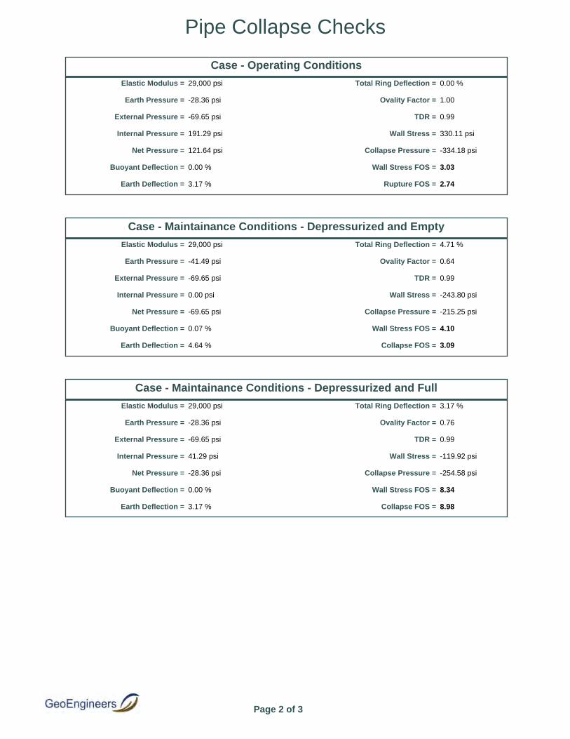
Case - Operating Conditions
Elastic Modulus = 29,000 psi Total Ring Deflection = 0.00 %
Earth Pressure = -28.36 psi Ovality Factor = 1.00
External Pressure = -69.65 psi TDR = 0.99
Internal Pressure = 191.29 psi Wall Stress = 330.11 psi
Net Pressure = 121.64 psi Collapse Pressure = -334.18 psi
Buoyant Deflection = 0.00 % Wall Stress FOS = 3.03
Earth Deflection = 3.17 % Rupture FOS = 2.74
Case - Maintainance Conditions - Depressurized and Empty
Elastic Modulus = 29,000 psi Total Ring Deflection = 4.71 %
Earth Pressure = -41.49 psi Ovality Factor = 0.64
External Pressure = -69.65 psi TDR = 0.99
Internal Pressure = 0.00 psi Wall Stress = -243.80 psi
Net Pressure = -69.65 psi Collapse Pressure = -215.25 psi
Buoyant Deflection = 0.07 % Wall Stress FOS = 4.10
Earth Deflection = 4.64 % Collapse FOS = 3.09
Case - Maintainance Conditions - Depressurized and Full
Elastic Modulus = 29,000 psi Total Ring Deflection = 3.17 %
Earth Pressure = -28.36 psi Ovality Factor = 0.76
External Pressure = -69.65 psi TDR = 0.99
Internal Pressure = 41.29 psi Wall Stress = -119.92 psi
Net Pressure = -28.36 psi Collapse Pressure = -254.58 psi
Buoyant Deflection = 0.00 % Wall Stress FOS = 8.34
Earth Deflection = 3.17 % Collapse FOS = 8.98
Page 2 of 3
Pipe Collapse Checks

Project Name: Yamhill River HDD Installations HDD Name: Yamhill River 20-inch HDD Owner: Westech Engineering
Project No: 10291-003-00 By: JAH Ck'd By: BCR Location: Dayton, OR Date: Thursday, November 15, 2018
Page 3 of 3
Pipe Collapse Checks
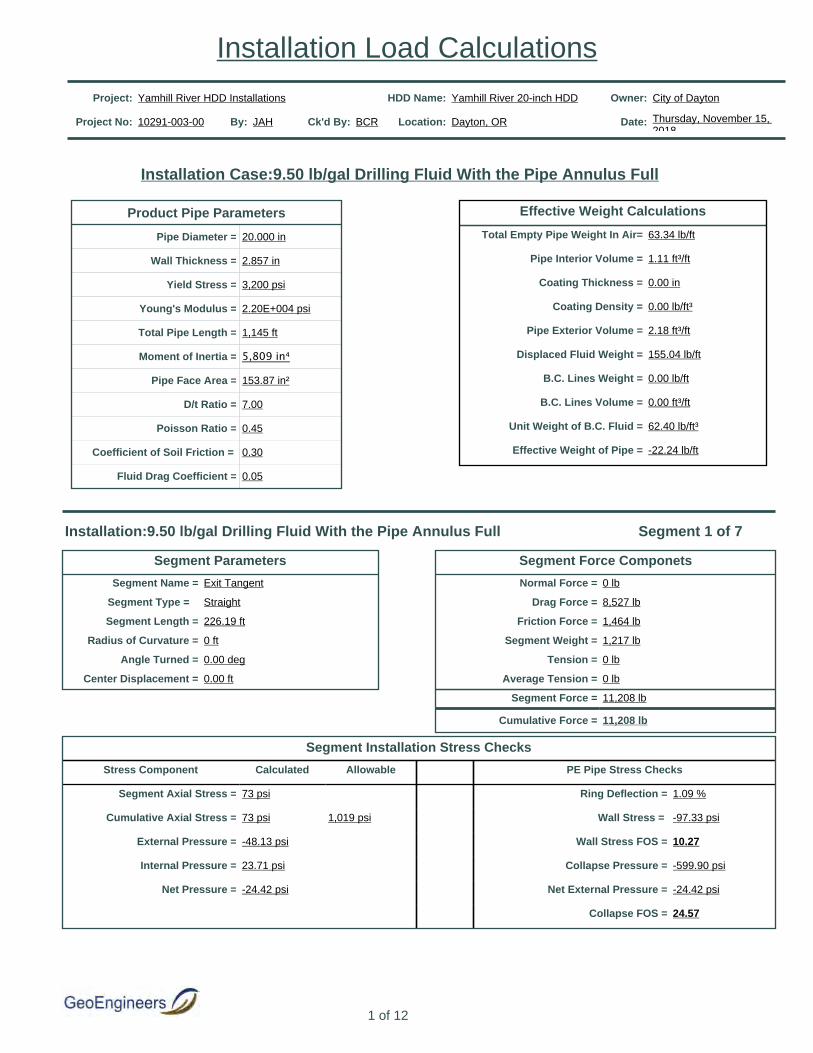
Project: Yamhill River HDD Installations HDD Name: Yamhill River 20-inch HDD Owner: City of Dayton
Project No: 10291-003-00 By: JAH Ck'd By: BCR Location: Dayton, OR Date: Thursday, November 15, 2018
Installation Case:9.50 lb/gal Drilling Fluid With the Pipe Annulus Full
Segment Parameters
Segment Name = Exit Tangent
Segment Type = Straight
Segment Length = 226.19 ft
Radius of Curvature = 0 ft
Angle Turned = 0.00 deg
Center Displacement = 0.00 ft
Segment Force Componets
Normal Force = 0 lb
Drag Force = 8,527 lb
Friction Force = 1,464 lb
Segment Weight = 1,217 lb
Tension = 0 lb
Average Tension = 0 lb
Segment Force = 11,208 lb
Cumulative Force = 11,208 lb
Segment Installation Stress Checks
Stress Component Calculated Allowable PE Pipe Stress Checks
Segment Axial Stress = 73 psi Ring Deflection = 1.09 %
Cumulative Axial Stress = 73 psi 1,019 psi Wall Stress = -97.33 psi
External Pressure = -48.13 psi Wall Stress FOS = 10.27
Internal Pressure = 23.71 psi Collapse Pressure = -599.90 psi
Net Pressure = -24.42 psi Net External Pressure = -24.42 psi
Collapse FOS = 24.57
Installation:9.50 lb/gal Drilling Fluid With the Pipe Annulus Full Segment 1 of 7
Product Pipe Parameters
Pipe Diameter = 20.000 in
Wall Thickness = 2.857 in
Yield Stress = 3,200 psi
Young's Modulus = 2.20E+004 psi
Total Pipe Length = 1,145 ft
Moment of Inertia = 5,809 in⁴
Pipe Face Area = 153.87 in²
D/t Ratio = 7.00
Poisson Ratio = 0.45
Coefficient of Soil Friction = 0.30
Fluid Drag Coefficient = 0.05
Effective Weight Calculations
Total Empty Pipe Weight In Air= 63.34 lb/ft
Pipe Interior Volume = 1.11 ft³/ft
Coating Thickness = 0.00 in
Coating Density = 0.00 lb/ft³
Pipe Exterior Volume = 2.18 ft³/ft
Displaced Fluid Weight = 155.04 lb/ft
B.C. Lines Weight = 0.00 lb/ft
B.C. Lines Volume = 0.00 ft³/ft
Unit Weight of B.C. Fluid = 62.40 lb/ft³
Effective Weight of Pipe = -22.24 lb/ft
1 of 12
Installation Load Calculations
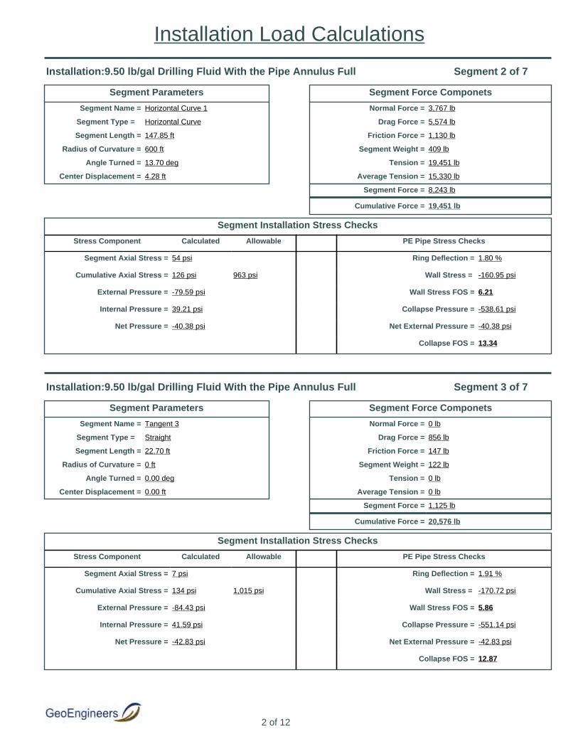
Segment Parameters
Segment Name = Horizontal Curve 1
Segment Type = Horizontal Curve
Segment Length = 147.85 ft
Radius of Curvature = 600 ft
Angle Turned = 13.70 deg
Center Displacement = 4.28 ft
Segment Force Componets
Normal Force = 3,767 lb
Drag Force = 5,574 lb
Friction Force = 1,130 lb
Segment Weight = 409 lb
Tension = 19,451 lb
Average Tension = 15,330 lb
Segment Force = 8,243 lb
Cumulative Force = 19,451 lb
Segment Installation Stress Checks
Stress Component Calculated Allowable PE Pipe Stress Checks
Segment Axial Stress = 54 psi Ring Deflection = 1.80 %
Cumulative Axial Stress = 126 psi 963 psi Wall Stress = -160.95 psi
External Pressure = -79.59 psi Wall Stress FOS = 6.21
Internal Pressure = 39.21 psi Collapse Pressure = -538.61 psi
Net Pressure = -40.38 psi Net External Pressure = -40.38 psi
Collapse FOS = 13.34
Installation:9.50 lb/gal Drilling Fluid With the Pipe Annulus Full Segment 2 of 7
Segment Parameters
Segment Name = Tangent 3
Segment Type = Straight
Segment Length = 22.70 ft
Radius of Curvature = 0 ft
Angle Turned = 0.00 deg
Center Displacement = 0.00 ft
Segment Force Componets
Normal Force = 0 lb
Drag Force = 856 lb
Friction Force = 147 lb
Segment Weight = 122 lb
Tension = 0 lb
Average Tension = 0 lb
Segment Force = 1,125 lb
Cumulative Force = 20,576 lb
Segment Installation Stress Checks
Stress Component Calculated Allowable PE Pipe Stress Checks
Segment Axial Stress = 7 psi Ring Deflection = 1.91 %
Cumulative Axial Stress = 134 psi 1,015 psi Wall Stress = -170.72 psi
External Pressure = -84.43 psi Wall Stress FOS = 5.86
Internal Pressure = 41.59 psi Collapse Pressure = -551.14 psi
Net Pressure = -42.83 psi Net External Pressure = -42.83 psi
Collapse FOS = 12.87
Installation:9.50 lb/gal Drilling Fluid With the Pipe Annulus Full Segment 3 of 7
2 of 12
Installation Load Calculations

Segment Parameters
Segment Name = Vertical Curve 2
Segment Type = Vertical Curve
Segment Length = 146.61 ft
Radius of Curvature = 600 ft
Angle Turned = 14.00 deg
Center Displacement = 4.47 ft
Segment Force Componets
Normal Force = 5,062 lb
Drag Force = 5,527 lb
Friction Force = 1,519 lb
Segment Weight = 397 lb
Tension = 29,538 lb
Average Tension = 25,057 lb
Segment Force = 8,962 lb
Cumulative Force = 29,538 lb
Segment Installation Stress Checks
Stress Component Calculated Allowable PE Pipe Stress Checks
Segment Axial Stress = 58 psi Ring Deflection = 2.26 %
Cumulative Axial Stress = 192 psi 961 psi Wall Stress = -202.42 psi
External Pressure = -100.10 psi Wall Stress FOS = 4.94
Internal Pressure = 49.31 psi Collapse Pressure = -506.91 psi
Net Pressure = -50.79 psi Net External Pressure = -50.79 psi
Collapse FOS = 9.98
Installation:9.50 lb/gal Drilling Fluid With the Pipe Annulus Full Segment 4 of 7
Segment Parameters
Segment Name = Tangent 2
Segment Type = Straight
Segment Length = 80.49 ft
Radius of Curvature = 0 ft
Angle Turned = 0.00 deg
Center Displacement = 0.00 ft
Segment Force Componets
Normal Force = 0 lb
Drag Force = 3,034 lb
Friction Force = 537 lb
Segment Weight = 0 lb
Tension = 0 lb
Average Tension = 0 lb
Segment Force = 3,571 lb
Cumulative Force = 33,109 lb
Segment Installation Stress Checks
Stress Component Calculated Allowable PE Pipe Stress Checks
Segment Axial Stress = 23 psi Ring Deflection = 2.26 %
Cumulative Axial Stress = 215 psi 1,014 psi Wall Stress = -202.42 psi
External Pressure = -100.10 psi Wall Stress FOS = 4.94
Internal Pressure = 49.31 psi Collapse Pressure = -522.42 psi
Net Pressure = -50.79 psi Net External Pressure = -50.79 psi
Collapse FOS = 10.29
Installation:9.50 lb/gal Drilling Fluid With the Pipe Annulus Full Segment 5 of 7
3 of 12
Installation Load Calculations

Segment Parameters
Segment Name = Vertical Curve 1
Segment Type = Vertical Curve
Segment Length = 125.66 ft
Radius of Curvature = 600 ft
Angle Turned = 12.00 deg
Center Displacement = 3.29 ft
Segment Force Componets
Normal Force = 5,688 lb
Drag Force = 4,737 lb
Friction Force = 1,706 lb
Segment Weight = -292 lb
Tension = 40,968 lb
Average Tension = 37,038 lb
Segment Force = 7,858 lb
Cumulative Force = 40,968 lb
Segment Installation Stress Checks
Stress Component Calculated Allowable PE Pipe Stress Checks
Segment Axial Stress = 51 psi Ring Deflection = 2.26 %
Cumulative Axial Stress = 266 psi 961 psi Wall Stress = -202.42 psi
External Pressure = -100.10 psi Wall Stress FOS = 4.94
Internal Pressure = 49.31 psi Collapse Pressure = -495.75 psi
Net Pressure = -50.79 psi Net External Pressure = -50.79 psi
Collapse FOS = 9.76
Installation:9.50 lb/gal Drilling Fluid With the Pipe Annulus Full Segment 6 of 7
Segment Parameters
Segment Name = Entry Tangent
Segment Type = Straight
Segment Length = 395.25 ft
Radius of Curvature = 0 ft
Angle Turned = 0.00 deg
Center Displacement = 0.00 ft
Segment Force Componets
Normal Force = 0 lb
Drag Force = 14,900 lb
Friction Force = 2,579 lb
Segment Weight = -1,827 lb
Tension = 0 lb
Average Tension = 0 lb
Segment Force = 15,652 lb
Cumulative Force = 56,620 lb
Segment Installation Stress Checks
Stress Component Calculated Allowable PE Pipe Stress Checks
Segment Axial Stress = 102 psi Ring Deflection = 2.00 %
Cumulative Axial Stress = 368 psi 1,015 psi Wall Stress = -179.10 psi
External Pressure = -88.57 psi Wall Stress FOS = 5.58
Internal Pressure = 43.63 psi Collapse Pressure = -512.36 psi
Net Pressure = -44.94 psi Net External Pressure = -44.94 psi
Collapse FOS = 11.40
Installation:9.50 lb/gal Drilling Fluid With the Pipe Annulus Full Segment 7 of 7
4 of 12
Installation Load Calculations
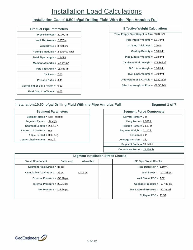
Installation Case:10.50 lb/gal Drilling Fluid With the Pipe Annulus Full
Segment Parameters
Segment Name = Exit Tangent
Segment Type = Straight
Segment Length = 226.19 ft
Radius of Curvature = 0 ft
Angle Turned = 0.00 deg
Center Displacement = 0.00 ft
Segment Force Componets
Normal Force = 0 lb
Drag Force = 8,527 lb
Friction Force = 2,539 lb
Segment Weight = 2,110 lb
Tension = 0 lb
Average Tension = 0 lb
Segment Force = 13,176 lb
Cumulative Force = 13,176 lb
Segment Installation Stress Checks
Stress Component Calculated Allowable PE Pipe Stress Checks
Segment Axial Stress = 86 psi Ring Deflection = 1.10 %
Cumulative Axial Stress = 86 psi 1,015 psi Wall Stress = -107.28 psi
External Pressure = -50.98 psi Wall Stress FOS = 9.32
Internal Pressure = 23.71 psi Collapse Pressure = -597.85 psi
Net Pressure = -27.26 psi Net External Pressure = -27.26 psi
Collapse FOS = 21.93
Installation:10.50 lb/gal Drilling Fluid With the Pipe Annulus Full Segment 1 of 7
Product Pipe Parameters
Pipe Diameter = 20.000 in
Wall Thickness = 2.857 in
Yield Stress = 3,200 psi
Young's Modulus = 2.20E+004 psi
Total Pipe Length = 1,145 ft
Moment of Inertia = 5,809 in⁴
Pipe Face Area = 153.87 in²
D/t Ratio = 7.00
Poisson Ratio = 0.45
Coefficient of Soil Friction = 0.30
Fluid Drag Coefficient = 0.05
Effective Weight Calculations
Total Empty Pipe Weight In Air= 63.34 lb/ft
Pipe Interior Volume = 1.11 ft³/ft
Coating Thickness = 0.00 in
Coating Density = 0.00 lb/ft³
Pipe Exterior Volume = 2.18 ft³/ft
Displaced Fluid Weight = 171.36 lb/ft
B.C. Lines Weight = 0.00 lb/ft
B.C. Lines Volume = 0.00 ft³/ft
Unit Weight of B.C. Fluid = 62.40 lb/ft³
Effective Weight of Pipe = -38.56 lb/ft
5 of 12
Installation Load Calculations

Segment Parameters
Segment Name = Horizontal Curve 1
Segment Type = Horizontal Curve
Segment Length = 147.85 ft
Radius of Curvature = 600 ft
Angle Turned = 13.70 deg
Center Displacement = 4.28 ft
Segment Force Componets
Normal Force = 5,371 lb
Drag Force = 5,574 lb
Friction Force = 1,611 lb
Segment Weight = 710 lb
Tension = 22,681 lb
Average Tension = 17,929 lb
Segment Force = 9,506 lb
Cumulative Force = 22,681 lb
Segment Installation Stress Checks
Stress Component Calculated Allowable PE Pipe Stress Checks
Segment Axial Stress = 62 psi Ring Deflection = 1.81 %
Cumulative Axial Stress = 147 psi 956 psi Wall Stress = -177.41 psi
External Pressure = -84.30 psi Wall Stress FOS = 5.64
Internal Pressure = 39.21 psi Collapse Pressure = -535.28 psi
Net Pressure = -45.08 psi Net External Pressure = -45.08 psi
Collapse FOS = 11.87
Installation:10.50 lb/gal Drilling Fluid With the Pipe Annulus Full Segment 2 of 7
Segment Parameters
Segment Name = Tangent 3
Segment Type = Straight
Segment Length = 22.70 ft
Radius of Curvature = 0 ft
Angle Turned = 0.00 deg
Center Displacement = 0.00 ft
Segment Force Componets
Normal Force = 0 lb
Drag Force = 856 lb
Friction Force = 255 lb
Segment Weight = 212 lb
Tension = 0 lb
Average Tension = 0 lb
Segment Force = 1,322 lb
Cumulative Force = 24,004 lb
Segment Installation Stress Checks
Stress Component Calculated Allowable PE Pipe Stress Checks
Segment Axial Stress = 9 psi Ring Deflection = 1.92 %
Cumulative Axial Stress = 156 psi 1,008 psi Wall Stress = -188.17 psi
External Pressure = -89.41 psi Wall Stress FOS = 5.31
Internal Pressure = 41.59 psi Collapse Pressure = -547.83 psi
Net Pressure = -47.82 psi Net External Pressure = -47.82 psi
Collapse FOS = 11.46
Installation:10.50 lb/gal Drilling Fluid With the Pipe Annulus Full Segment 3 of 7
6 of 12
Installation Load Calculations

Segment Parameters
Segment Name = Vertical Curve 2
Segment Type = Vertical Curve
Segment Length = 146.61 ft
Radius of Curvature = 600 ft
Angle Turned = 14.00 deg
Center Displacement = 4.47 ft
Segment Force Componets
Normal Force = 6,844 lb
Drag Force = 5,527 lb
Friction Force = 2,053 lb
Segment Weight = 689 lb
Tension = 34,326 lb
Average Tension = 29,165 lb
Segment Force = 10,322 lb
Cumulative Force = 34,326 lb
Segment Installation Stress Checks
Stress Component Calculated Allowable PE Pipe Stress Checks
Segment Axial Stress = 67 psi Ring Deflection = 2.27 %
Cumulative Axial Stress = 223 psi 952 psi Wall Stress = -223.12 psi
External Pressure = -106.01 psi Wall Stress FOS = 4.48
Internal Pressure = 49.31 psi Collapse Pressure = -502.09 psi
Net Pressure = -56.70 psi Net External Pressure = -56.70 psi
Collapse FOS = 8.86
Installation:10.50 lb/gal Drilling Fluid With the Pipe Annulus Full Segment 4 of 7
Segment Parameters
Segment Name = Tangent 2
Segment Type = Straight
Segment Length = 80.49 ft
Radius of Curvature = 0 ft
Angle Turned = 0.00 deg
Center Displacement = 0.00 ft
Segment Force Componets
Normal Force = 0 lb
Drag Force = 3,034 lb
Friction Force = 931 lb
Segment Weight = 0 lb
Tension = 0 lb
Average Tension = 0 lb
Segment Force = 3,965 lb
Cumulative Force = 38,292 lb
Segment Installation Stress Checks
Stress Component Calculated Allowable PE Pipe Stress Checks
Segment Axial Stress = 26 psi Ring Deflection = 2.27 %
Cumulative Axial Stress = 249 psi 1,004 psi Wall Stress = -223.12 psi
External Pressure = -106.01 psi Wall Stress FOS = 4.48
Internal Pressure = 49.31 psi Collapse Pressure = -517.47 psi
Net Pressure = -56.70 psi Net External Pressure = -56.70 psi
Collapse FOS = 9.13
Installation:10.50 lb/gal Drilling Fluid With the Pipe Annulus Full Segment 5 of 7
7 of 12
Installation Load Calculations
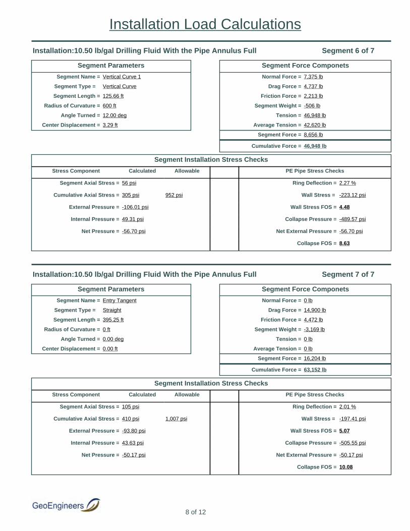
Segment Parameters
Segment Name = Vertical Curve 1
Segment Type = Vertical Curve
Segment Length = 125.66 ft
Radius of Curvature = 600 ft
Angle Turned = 12.00 deg
Center Displacement = 3.29 ft
Segment Force Componets
Normal Force = 7,375 lb
Drag Force = 4,737 lb
Friction Force = 2,213 lb
Segment Weight = -506 lb
Tension = 46,948 lb
Average Tension = 42,620 lb
Segment Force = 8,656 lb
Cumulative Force = 46,948 lb
Segment Installation Stress Checks
Stress Component Calculated Allowable PE Pipe Stress Checks
Segment Axial Stress = 56 psi Ring Deflection = 2.27 %
Cumulative Axial Stress = 305 psi 952 psi Wall Stress = -223.12 psi
External Pressure = -106.01 psi Wall Stress FOS = 4.48
Internal Pressure = 49.31 psi Collapse Pressure = -489.57 psi
Net Pressure = -56.70 psi Net External Pressure = -56.70 psi
Collapse FOS = 8.63
Installation:10.50 lb/gal Drilling Fluid With the Pipe Annulus Full Segment 6 of 7
Segment Parameters
Segment Name = Entry Tangent
Segment Type = Straight
Segment Length = 395.25 ft
Radius of Curvature = 0 ft
Angle Turned = 0.00 deg
Center Displacement = 0.00 ft
Segment Force Componets
Normal Force = 0 lb
Drag Force = 14,900 lb
Friction Force = 4,472 lb
Segment Weight = -3,169 lb
Tension = 0 lb
Average Tension = 0 lb
Segment Force = 16,204 lb
Cumulative Force = 63,152 lb
Segment Installation Stress Checks
Stress Component Calculated Allowable PE Pipe Stress Checks
Segment Axial Stress = 105 psi Ring Deflection = 2.01 %
Cumulative Axial Stress = 410 psi 1,007 psi Wall Stress = -197.41 psi
External Pressure = -93.80 psi Wall Stress FOS = 5.07
Internal Pressure = 43.63 psi Collapse Pressure = -505.55 psi
Net Pressure = -50.17 psi Net External Pressure = -50.17 psi
Collapse FOS = 10.08
Installation:10.50 lb/gal Drilling Fluid With the Pipe Annulus Full Segment 7 of 7
8 of 12
Installation Load Calculations

Installation Case:12.00 lb/gal Drilling Fluid With the Pipe Annulus Full
Segment Parameters
Segment Name = Exit Tangent
Segment Type = Straight
Segment Length = 226.19 ft
Radius of Curvature = 0 ft
Angle Turned = 0.00 deg
Center Displacement = 0.00 ft
Segment Force Componets
Normal Force = 0 lb
Drag Force = 8,527 lb
Friction Force = 4,150 lb
Segment Weight = 3,449 lb
Tension = 0 lb
Average Tension = 0 lb
Segment Force = 16,127 lb
Cumulative Force = 16,127 lb
Segment Installation Stress Checks
Stress Component Calculated Allowable PE Pipe Stress Checks
Segment Axial Stress = 105 psi Ring Deflection = 1.10 %
Cumulative Axial Stress = 105 psi 1,008 psi Wall Stress = -122.21 psi
External Pressure = -55.24 psi Wall Stress FOS = 8.18
Internal Pressure = 23.71 psi Collapse Pressure = -594.75 psi
Net Pressure = -31.53 psi Net External Pressure = -31.53 psi
Collapse FOS = 18.86
Installation:12.00 lb/gal Drilling Fluid With the Pipe Annulus Full Segment 1 of 7
Product Pipe Parameters
Pipe Diameter = 20.000 in
Wall Thickness = 2.857 in
Yield Stress = 3,200 psi
Young's Modulus = 2.20E+004 psi
Total Pipe Length = 1,145 ft
Moment of Inertia = 5,809 in⁴
Pipe Face Area = 153.87 in²
D/t Ratio = 7.00
Poisson Ratio = 0.45
Coefficient of Soil Friction = 0.30
Fluid Drag Coefficient = 0.05
Effective Weight Calculations
Total Empty Pipe Weight In Air= 63.34 lb/ft
Pipe Interior Volume = 1.11 ft³/ft
Coating Thickness = 0.00 in
Coating Density = 0.00 lb/ft³
Pipe Exterior Volume = 2.18 ft³/ft
Displaced Fluid Weight = 195.84 lb/ft
B.C. Lines Weight = 0.00 lb/ft
B.C. Lines Volume = 0.00 ft³/ft
Unit Weight of B.C. Fluid = 62.40 lb/ft³
Effective Weight of Pipe = -63.04 lb/ft
9 of 12
Installation Load Calculations

Segment Parameters
Segment Name = Horizontal Curve 1
Segment Type = Horizontal Curve
Segment Length = 147.85 ft
Radius of Curvature = 600 ft
Angle Turned = 13.70 deg
Center Displacement = 4.28 ft
Segment Force Componets
Normal Force = 7,756 lb
Drag Force = 5,574 lb
Friction Force = 2,327 lb
Segment Weight = 1,160 lb
Tension = 27,514 lb
Average Tension = 21,821 lb
Segment Force = 11,387 lb
Cumulative Force = 27,514 lb
Segment Installation Stress Checks
Stress Component Calculated Allowable PE Pipe Stress Checks
Segment Axial Stress = 74 psi Ring Deflection = 1.81 %
Cumulative Axial Stress = 179 psi 944 psi Wall Stress = -202.09 psi
External Pressure = -91.35 psi Wall Stress FOS = 4.95
Internal Pressure = 39.21 psi Collapse Pressure = -530.22 psi
Net Pressure = -52.13 psi Net External Pressure = -52.13 psi
Collapse FOS = 10.17
Installation:12.00 lb/gal Drilling Fluid With the Pipe Annulus Full Segment 2 of 7
Segment Parameters
Segment Name = Tangent 3
Segment Type = Straight
Segment Length = 22.70 ft
Radius of Curvature = 0 ft
Angle Turned = 0.00 deg
Center Displacement = 0.00 ft
Segment Force Componets
Normal Force = 0 lb
Drag Force = 856 lb
Friction Force = 417 lb
Segment Weight = 346 lb
Tension = 0 lb
Average Tension = 0 lb
Segment Force = 1,619 lb
Cumulative Force = 29,133 lb
Segment Installation Stress Checks
Stress Component Calculated Allowable PE Pipe Stress Checks
Segment Axial Stress = 11 psi Ring Deflection = 1.92 %
Cumulative Axial Stress = 189 psi 995 psi Wall Stress = -214.35 psi
External Pressure = -96.89 psi Wall Stress FOS = 4.67
Internal Pressure = 41.59 psi Collapse Pressure = -542.81 psi
Net Pressure = -55.30 psi Net External Pressure = -55.30 psi
Collapse FOS = 9.82
Installation:12.00 lb/gal Drilling Fluid With the Pipe Annulus Full Segment 3 of 7
10 of 12
Installation Load Calculations
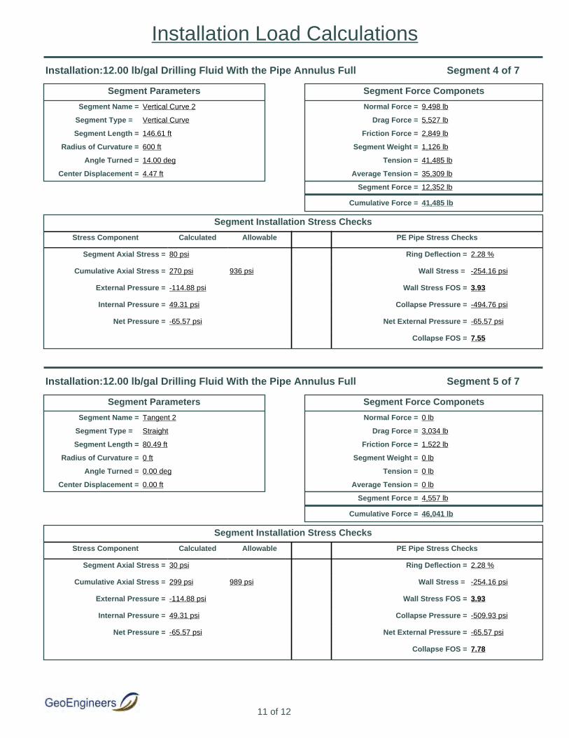
Segment Parameters
Segment Name = Vertical Curve 2
Segment Type = Vertical Curve
Segment Length = 146.61 ft
Radius of Curvature = 600 ft
Angle Turned = 14.00 deg
Center Displacement = 4.47 ft
Segment Force Componets
Normal Force = 9,498 lb
Drag Force = 5,527 lb
Friction Force = 2,849 lb
Segment Weight = 1,126 lb
Tension = 41,485 lb
Average Tension = 35,309 lb
Segment Force = 12,352 lb
Cumulative Force = 41,485 lb
Segment Installation Stress Checks
Stress Component Calculated Allowable PE Pipe Stress Checks
Segment Axial Stress = 80 psi Ring Deflection = 2.28 %
Cumulative Axial Stress = 270 psi 936 psi Wall Stress = -254.16 psi
External Pressure = -114.88 psi Wall Stress FOS = 3.93
Internal Pressure = 49.31 psi Collapse Pressure = -494.76 psi
Net Pressure = -65.57 psi Net External Pressure = -65.57 psi
Collapse FOS = 7.55
Installation:12.00 lb/gal Drilling Fluid With the Pipe Annulus Full Segment 4 of 7
Segment Parameters
Segment Name = Tangent 2
Segment Type = Straight
Segment Length = 80.49 ft
Radius of Curvature = 0 ft
Angle Turned = 0.00 deg
Center Displacement = 0.00 ft
Segment Force Componets
Normal Force = 0 lb
Drag Force = 3,034 lb
Friction Force = 1,522 lb
Segment Weight = 0 lb
Tension = 0 lb
Average Tension = 0 lb
Segment Force = 4,557 lb
Cumulative Force = 46,041 lb
Segment Installation Stress Checks
Stress Component Calculated Allowable PE Pipe Stress Checks
Segment Axial Stress = 30 psi Ring Deflection = 2.28 %
Cumulative Axial Stress = 299 psi 989 psi Wall Stress = -254.16 psi
External Pressure = -114.88 psi Wall Stress FOS = 3.93
Internal Pressure = 49.31 psi Collapse Pressure = -509.93 psi
Net Pressure = -65.57 psi Net External Pressure = -65.57 psi
Collapse FOS = 7.78
Installation:12.00 lb/gal Drilling Fluid With the Pipe Annulus Full Segment 5 of 7
11 of 12
Installation Load Calculations

Segment Parameters
Segment Name = Vertical Curve 1
Segment Type = Vertical Curve
Segment Length = 125.66 ft
Radius of Curvature = 600 ft
Angle Turned = 12.00 deg
Center Displacement = 3.29 ft
Segment Force Componets
Normal Force = 9,889 lb
Drag Force = 4,737 lb
Friction Force = 2,967 lb
Segment Weight = -828 lb
Tension = 55,884 lb
Average Tension = 50,963 lb
Segment Force = 9,843 lb
Cumulative Force = 55,884 lb
Segment Installation Stress Checks
Stress Component Calculated Allowable PE Pipe Stress Checks
Segment Axial Stress = 64 psi Ring Deflection = 2.28 %
Cumulative Axial Stress = 363 psi 936 psi Wall Stress = -254.16 psi
External Pressure = -114.88 psi Wall Stress FOS = 3.93
Internal Pressure = 49.31 psi Collapse Pressure = -480.11 psi
Net Pressure = -65.57 psi Net External Pressure = -65.57 psi
Collapse FOS = 7.32
Installation:12.00 lb/gal Drilling Fluid With the Pipe Annulus Full Segment 6 of 7
Segment Parameters
Segment Name = Entry Tangent
Segment Type = Straight
Segment Length = 395.25 ft
Radius of Curvature = 0 ft
Angle Turned = 0.00 deg
Center Displacement = 0.00 ft
Segment Force Componets
Normal Force = 0 lb
Drag Force = 14,900 lb
Friction Force = 7,311 lb
Segment Weight = -5,180 lb
Tension = 0 lb
Average Tension = 0 lb
Segment Force = 17,032 lb
Cumulative Force = 72,916 lb
Segment Installation Stress Checks
Stress Component Calculated Allowable PE Pipe Stress Checks
Segment Axial Stress = 111 psi Ring Deflection = 2.01 %
Cumulative Axial Stress = 474 psi 993 psi Wall Stress = -224.87 psi
External Pressure = -101.65 psi Wall Stress FOS = 4.45
Internal Pressure = 43.63 psi Collapse Pressure = -495.12 psi
Net Pressure = -58.01 psi Net External Pressure = -58.01 psi
Collapse FOS = 8.53
Installation:12.00 lb/gal Drilling Fluid With the Pipe Annulus Full Segment 7 of 7
12 of 12
Installation Load Calculations

APPENDIX C The Horizontal Directional Drilling Process

March 26, 2019 | Page C-1 File No. 10291-003-00
APPENDIX C THE HORIZONTAL DIRECTIONAL DRILLING PROCESS
General
HDD is a construction method to install pipelines beneath rivers, wetlands and other features that require special attention to environmental and logistical concerns. In the HDD process, there are three basic steps to install a pipeline crossing: pilot hole, reaming and pullback. The following sections give a general description of each stage of the HDD process.
Pilot Hole Process
The first stage of the HDD process consists of directionally drilling a small-diameter pilot hole along a predetermined path in accordance with the project plan and profile drawing. Based on the design parameters, the minimum allowable three-joint radius over any consecutive three-joint drill pipe section is established to reduce the risk of overstressing the carrier pipe during installation. Under the generally accepted industry standard for steel pipe design, the design radius in feet for the entry and exit vertical curves is typically 100 times the carrier pipe diameter in inches (for example, 12-inch nominal diameter pipe x 100 = 1,200-foot design radius). However, radii for HDPE pipe can be much lower and are generally limited by the minimum bending radius of the HDPE pipe, and/or the minimum bending radius of the drill pipe used to drill the pilot hole. Depending on the proposed operating conditions, pipe specification and geometric considerations, the design radii for the horizontal and vertical curves may vary from normal industry design standards.
Drilling fluid is pumped through the drill pipe string to aid the drill bit in cutting the soil and/or rock material. In soils, the pilot hole is typically advanced using a jetting assembly while bedrock is drilled using a positive displacement mud motor (see Photographs C-1 through C-3). The drilling fluid also helps lubricate the drill stem, suspend and carry the drilled cuttings to the surface, and form a wall cake to help support the hole and reduce the potential for infiltration from or drilling fluid loss to the formation.
While advancing the pilot hole, directional control is achieved by using a non-rotating drill pipe string with an asymmetrical leading edge. The asymmetry of the leading edge creates a steering bias, which allows the operator to control the direction of the drill bit. The actual path of the pilot hole is evaluated during pilot hole operations by a monitoring and control system, which tracks the progress and location of the bottom
Photograph C-1 - Typical Jetting Assembly with Orientation Sub and Milled Tooth Tri-Cone Drill Bit
Photograph C-2 – Positive Displacement Mud Motor with Polycrystalline Diamond Compact (PDC) Drill Bit
Photograph C-3 - Jetting Assembly with Duck Bill Drill Bit

March 26, 2019 | Page C-2 File No. 10291-003-00
hole assembly (BHA). The horizontal and vertical position of the pilot hole is typically surveyed by two different methods: (1) downhole survey tools that use an instrument referred to as a probe that utilizes the Earth’s gravitational and magnetic fields to determine the inclination and azimuth of the BHA which are used to calculate its position; and (2) a secondary, TruTracker, ParaTrack or equivalent survey system that uses a wire installed on the ground surface. By inducing an electric current in the wire, a magnetic field is generated that the probe uses to determine its location relative to the wire. The most commonly used wire layout is a survey coil loop that is laid on the ground surface along the alignment. The survey coil loop is often positioned at least as wide as the survey probe is deep. Typically, multiple survey coils will be installed, with at least one on each side of the feature being crossed. If the ParaTrack survey system is used, it is common for one side of the survey coil to be laid down the HDD centerline with the return wire offset from the centerline a minimum distance approximately equal to the maximum depth of the HDD. The placement of the survey coil is limited to areas where ground surface conditions and agreements with landowner’s permit. If ground conditions or landowner agreements do not allow for the installation of a survey coil, an AC solenoid (beacon) may be used with the ParaTrack system. The beacon does not require a coil wire to be installed but does require repositioning, generally along centerline of the alignment, as the pilot hole progresses. The position of the BHA is calculated using each survey method after each segment (joint) of drill pipe has been drilled. Depending on the scale of the project and the size of the HDD drill rig utilized during construction, the drill pipe joints used to complete the pilot hole will typically be 15, 20 or 30 feet long.
A pilot hole surveying technique has been developed that uses an inertial measurement unit to calculate the position of the BHA as the pilot hole progresses. The inclination and azimuth of the BHA are calculated through the use of fiber-optic gyroscopes rather than the Earth’s gravitational and magnetic fields. The use of a survey coil installed along the alignment is not utilized with this system. This type of system has seen more widespread use in the United States in the past several years and could be considered as an alternative to the traditional surveying methods; however, the use of this tool requires a minimum pilot hole diameter of approximately 8 inches and is more sensitive to vibration which could be problematic when used to drill rock.
When hole stability or drilling fluid surface releases are a concern on the entry side, the HDD contractor may choose to install a small-diameter casing (generally 12 to 16 inches in diameter). The casing is typically pushed and/or rotated over the drill pipe string in 15- to 40-foot sections. These sections are typically welded together during installation. However, if hydraulic fracture and drilling fluid surface release is a concern near the entry or exit points where casing will be installed, the casing should be advanced prior to initiating pilot hole operations. As sections are added, the casing will continue to be advanced to a depth necessary to maintain hole stability or reduce the risk of hydraulic fracture and drilling fluid surface release. The casing is then typically extracted before or during the hole opening process. This methodology is most commonly used in soft or loose soil where the drill path is shallow and where gravel or cobbles are anticipated. In addition to providing hole stability and reducing the potential for drilling fluid surface releases, the casing can provide a reaction mass for allowing a greater transfer of axial loads through the downhole drill pipe string to the drill bit.
Observations of subsurface conditions, drilling data and drilling fluid properties during the pilot hole operations provide information to the HDD contractor that can be compared to the anticipated subsurface conditions. These observations can aid in confirming that the proper hole opening techniques have been selected. The information obtained from the pilot hole includes the pilot hole survey data, rates of
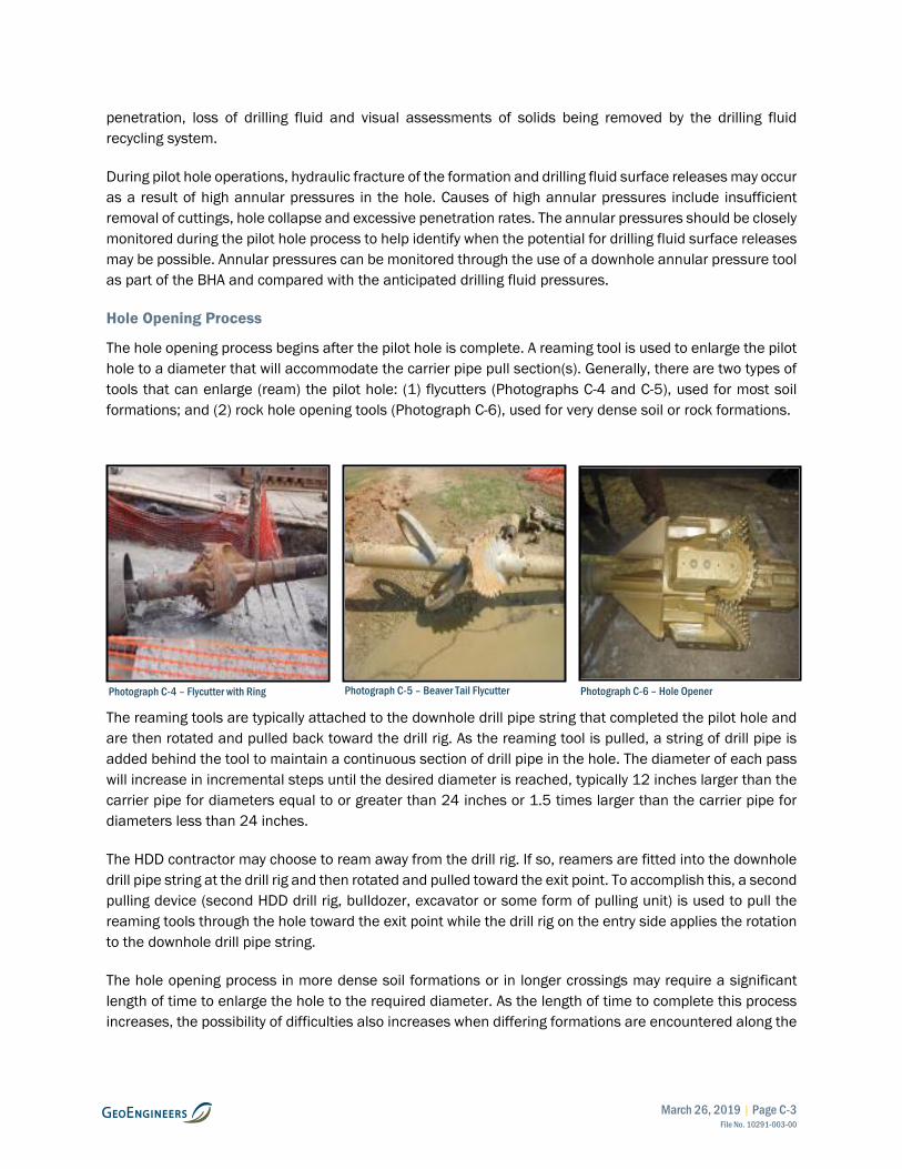
March 26, 2019 | Page C-3 File No. 10291-003-00
penetration, loss of drilling fluid and visual assessments of solids being removed by the drilling fluid recycling system.
During pilot hole operations, hydraulic fracture of the formation and drilling fluid surface releases may occur as a result of high annular pressures in the hole. Causes of high annular pressures include insufficient removal of cuttings, hole collapse and excessive penetration rates. The annular pressures should be closely monitored during the pilot hole process to help identify when the potential for drilling fluid surface releases may be possible. Annular pressures can be monitored through the use of a downhole annular pressure tool as part of the BHA and compared with the anticipated drilling fluid pressures.
Hole Opening Process
The hole opening process begins after the pilot hole is complete. A reaming tool is used to enlarge the pilot hole to a diameter that will accommodate the carrier pipe pull section(s). Generally, there are two types of tools that can enlarge (ream) the pilot hole: (1) flycutters (Photographs C-4 and C-5), used for most soil formations; and (2) rock hole opening tools (Photograph C-6), used for very dense soil or rock formations.
The reaming tools are typically attached to the downhole drill pipe string that completed the pilot hole and are then rotated and pulled back toward the drill rig. As the reaming tool is pulled, a string of drill pipe is added behind the tool to maintain a continuous section of drill pipe in the hole. The diameter of each pass will increase in incremental steps until the desired diameter is reached, typically 12 inches larger than the carrier pipe for diameters equal to or greater than 24 inches or 1.5 times larger than the carrier pipe for diameters less than 24 inches.
The HDD contractor may choose to ream away from the drill rig. If so, reamers are fitted into the downhole drill pipe string at the drill rig and then rotated and pulled toward the exit point. To accomplish this, a second pulling device (second HDD drill rig, bulldozer, excavator or some form of pulling unit) is used to pull the reaming tools through the hole toward the exit point while the drill rig on the entry side applies the rotation to the downhole drill pipe string.
The hole opening process in more dense soil formations or in longer crossings may require a significant length of time to enlarge the hole to the required diameter. As the length of time to complete this process increases, the possibility of difficulties also increases when differing formations are encountered along the
Photograph C-4 – Flycutter with Ring Photograph C-5 – Beaver Tail Flycutter Photograph C-6 – Hole Opener
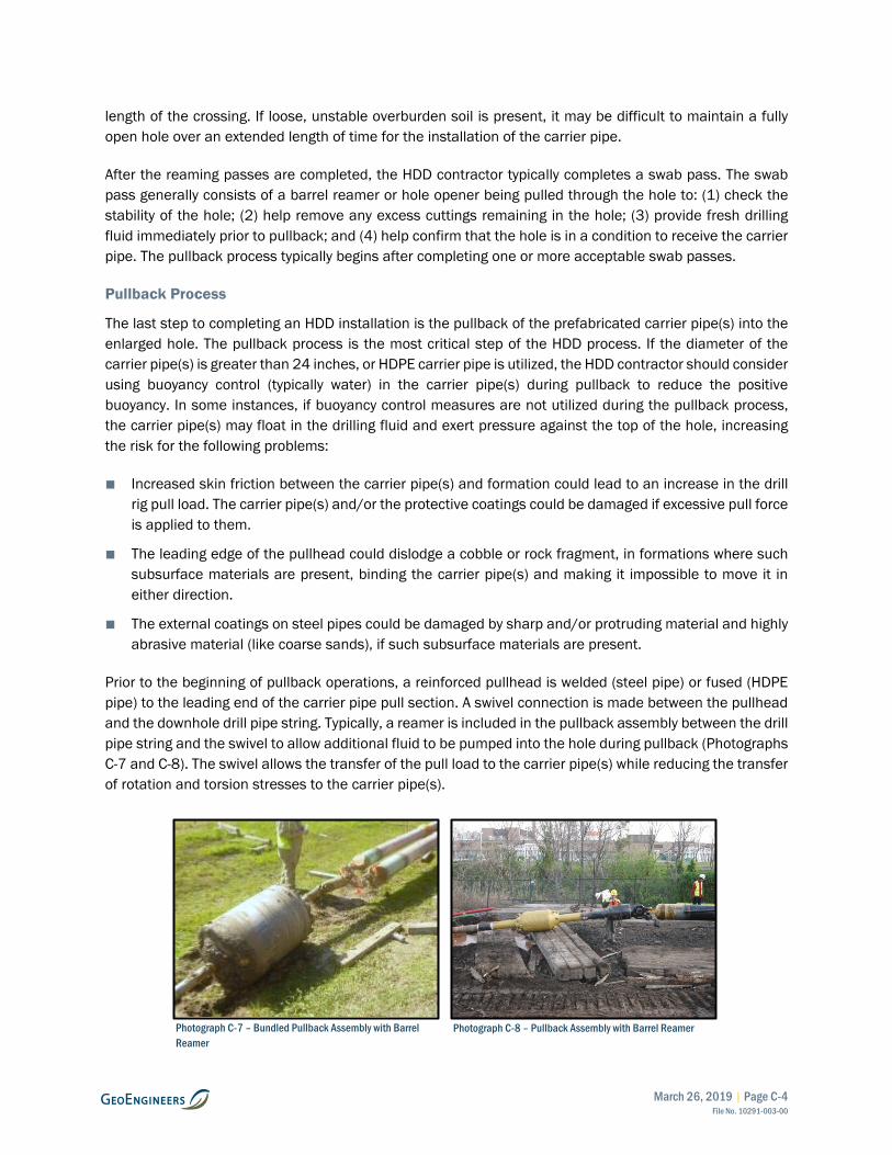
March 26, 2019 | Page C-4 File No. 10291-003-00
length of the crossing. If loose, unstable overburden soil is present, it may be difficult to maintain a fully open hole over an extended length of time for the installation of the carrier pipe.
After the reaming passes are completed, the HDD contractor typically completes a swab pass. The swab pass generally consists of a barrel reamer or hole opener being pulled through the hole to: (1) check the stability of the hole; (2) help remove any excess cuttings remaining in the hole; (3) provide fresh drilling fluid immediately prior to pullback; and (4) help confirm that the hole is in a condition to receive the carrier pipe. The pullback process typically begins after completing one or more acceptable swab passes.
Pullback Process
The last step to completing an HDD installation is the pullback of the prefabricated carrier pipe(s) into the enlarged hole. The pullback process is the most critical step of the HDD process. If the diameter of the carrier pipe(s) is greater than 24 inches, or HDPE carrier pipe is utilized, the HDD contractor should consider using buoyancy control (typically water) in the carrier pipe(s) during pullback to reduce the positive buoyancy. In some instances, if buoyancy control measures are not utilized during the pullback process, the carrier pipe(s) may float in the drilling fluid and exert pressure against the top of the hole, increasing the risk for the following problems:
■ Increased skin friction between the carrier pipe(s) and formation could lead to an increase in the drill rig pull load. The carrier pipe(s) and/or the protective coatings could be damaged if excessive pull force is applied to them.
■ The leading edge of the pullhead could dislodge a cobble or rock fragment, in formations where such subsurface materials are present, binding the carrier pipe(s) and making it impossible to move it in either direction.
■ The external coatings on steel pipes could be damaged by sharp and/or protruding material and highly abrasive material (like coarse sands), if such subsurface materials are present.
Prior to the beginning of pullback operations, a reinforced pullhead is welded (steel pipe) or fused (HDPE pipe) to the leading end of the carrier pipe pull section. A swivel connection is made between the pullhead and the downhole drill pipe string. Typically, a reamer is included in the pullback assembly between the drill pipe string and the swivel to allow additional fluid to be pumped into the hole during pullback (Photographs C-7 and C-8). The swivel allows the transfer of the pull load to the carrier pipe(s) while reducing the transfer of rotation and torsion stresses to the carrier pipe(s).
Photograph C-8 – Pullback Assembly with Barrel Reamer Photograph C-7 – Bundled Pullback Assembly with Barrel Reamer
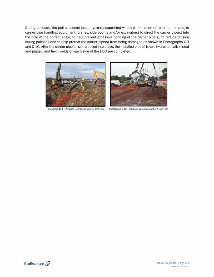
March 26, 2019 | Page C-5 File No. 10291-003-00
During pullback, the pull section(s) is/are typically supported with a combination of roller stands and/or carrier pipe handling equipment (cranes, side booms and/or excavators) to direct the carrier pipe(s) into the hole at the correct angle, to help prevent excessive bending of the carrier pipe(s), to reduce tension during pullback and to help protect the carrier pipe(s) from being damaged as shown in Photographs C-9 and C-10. After the carrier pipe(s) is/are pulled into place, the installed pipe(s) is/are hydrostatically tested and pigged, and tie-in welds on each side of the HDD are completed.
Photograph C-9 – Pullback Operations with 42-Inch Pipe
Photograph C-10 – Pullback Operations with 42-Inch Pipe

APPENDIX D Report Limitations and Guidelines for Use

March 26, 2019 | Page D-1 File No. 10291-003-00
APPENDIX D REPORT LIMITATIONS AND GUIDELINES FOR USE1
This appendix provides information to help you manage your risks with respect to the use of this report.
Geotechnical and Environmental Services Are Performed for Specific Purposes, Persons and Projects
This report has been prepared for the exclusive use of Westech Engineering, Inc., City of Dayton, and their authorized agents. This report is not intended for use by others, and the information contained herein is not applicable to other sites.
GeoEngineers structures our services to meet the specific needs of our clients. For example, a geotechnical or geologic study conducted for a civil engineer or architect may not fulfill the needs of a construction contractor or even another civil engineer or architect that are involved in the same project. Similarly, an environmental assessment study conducted for a property owner may not fulfill the needs of a prospective purchaser of the same property. Because each study is unique, each report is unique, prepared solely for the specific client and project site. Our report is prepared for the exclusive use of our Client. No other party may rely on the product of our services unless we agree in advance to such reliance in writing. This is to provide our firm with reasonable protection against open-ended liability claims by third parties with whom there would otherwise be no contractual limits to their actions. Within the limitations of scope, schedule and budget, our services have been executed in accordance with our Agreement with the Client and generally accepted geotechnical practices in this area at the time this report was prepared. This report should not be applied for any purpose or project except the one originally contemplated.
A Geotechnical Engineering or Environmental Report Is Based on a Unique Set of Project-Specific Factors
This report has been prepared for the proposed 18-Inch and 20-Inch Yamhill River HDD installations located in Dayton, Oregon. GeoEngineers considered a number of unique, project-specific factors when establishing the scope of services for this project and report. Unless GeoEngineers specifically indicates otherwise, do not rely on this report if it was:
■ not prepared for you,
■ not prepared for your project,
■ not prepared for the specific site explored, or
■ completed before important project changes were made.
For example, changes that can affect the applicability of this report include those that affect:
■ the function of the proposed structure;
■ elevation, configuration, location, orientation or weight of the proposed structure;
1 Developed based on material provided by ASFE/The Best People on Earth, Professional Firms Practicing in the Geosciences; www.asfe.org.
March 26, 2019 | Page D-2 File No. 10291-003-00
■ composition of the design team; or
■ project ownership.
If important changes are made after the date of this report, GeoEngineers should be given the opportunity to review our interpretations and recommendations and provide written modifications or confirmation, as appropriate.
Subsurface Conditions Can Change
This report is based on conditions that existed at the time the study was performed. The findings and conclusions of this report may be affected by the passage of time, by manmade events such as construction on or adjacent to the site, by new releases of hazardous substances, or by natural events such as floods, earthquakes, slope instability or groundwater fluctuations. Always contact GeoEngineers before applying a report to determine if it remains applicable.
Most Geotechnical and Environmental Findings Are Professional Opinions
Our interpretations of subsurface conditions are based on field observations and laboratory test results from widely spaced sampling locations at the site. Site exploration identifies subsurface conditions only at those points where subsurface tests are conducted, or samples are taken. GeoEngineers reviewed field and laboratory data and then applied our professional judgment to render an opinion about subsurface conditions throughout the site. Actual subsurface conditions may differ, sometimes significantly, from those indicated in this report. Our report, conclusions and interpretations should not be construed as a warranty of the subsurface conditions.
Geotechnical Engineering Report Recommendations Are Not Final
Do not over-rely on the preliminary construction recommendations included in this report. These recommendations are not final, because they were developed principally from GeoEngineers’ professional judgment and opinion. GeoEngineers’ recommendations can be finalized only by observing actual subsurface conditions revealed during construction. GeoEngineers cannot assume responsibility or liability for this report’s recommendations if we do not perform construction observation.
Sufficient monitoring and consultation by GeoEngineers should be provided during construction to confirm that the conditions encountered are consistent with those indicated by the explorations, to provide recommendations for design changes should the conditions revealed during the work differ from those anticipated, and to evaluate whether or not construction activities are completed in accordance with our recommendations. Retaining GeoEngineers for construction observation for this project is the most effective method of managing the risks associated with unanticipated conditions.
A Geotechnical Engineering or Geologic Report Could Be Subject to Misinterpretation
Misinterpretation of this report by other design team members can result in costly problems. You could lower that risk by having GeoEngineers confer with appropriate members of the design team after submitting the report. Also, retain GeoEngineers to review pertinent elements of the design team’s plans and specifications. Contractors can also misinterpret a geotechnical engineering or geologic report. Reduce that risk by having GeoEngineers participate in pre-bid and preconstruction conferences, and by providing construction observation.

March 26, 2019 | Page D-3 File No. 10291-003-00
Do Not Redraw the Exploration Logs
Geotechnical engineers and geologists prepare final boring and testing logs based upon their interpretation of field logs and laboratory data. To prevent errors or omissions, the logs included in a geotechnical engineering or geologic report should never be redrawn for inclusion in architectural or other design drawings. Only photographic or electronic reproduction is acceptable but recognize that separating logs from the report can elevate risk.
Give Contractors a Complete Report and Guidance
Some owners and design professionals believe they can make contractors liable for unanticipated subsurface conditions by limiting what they provide for bid preparation. To help prevent costly problems, give contractors the complete geotechnical engineering or geologic report, but preface it with a clearly written letter of transmittal. In that letter, advise contractors that the report was not prepared for purposes of bid development and that the report’s accuracy is limited; encourage them to confer with GeoEngineers and/or to conduct additional study to obtain the specific types of information they need or prefer. A pre-bid conference can also be valuable. Be sure contractors have sufficient time to perform additional study. Only then might an owner be in a position to give contractors the best information available, while requiring them to at least share the financial responsibilities stemming from unanticipated conditions. Further, a contingency for unanticipated conditions should be included in your project budget and schedule.
Contractors Are Responsible for Site Safety on Their Own Construction Projects
Our geotechnical recommendations are not intended to direct the contractor’s procedures, methods, schedule or management of the work site. The contractor is solely responsible for job site safety and for managing construction operations to minimize risks to on-site personnel and to adjacent properties.
Read These Provisions Closely
Some clients, design professionals and contractors may not recognize that the geoscience practices (geotechnical engineering or geology) are far less exact than other engineering and natural science disciplines. This lack of understanding can create unrealistic expectations that could lead to disappointments, claims and disputes. GeoEngineers includes these explanatory “limitations” provisions in our reports to help reduce such risks. Please confer with GeoEngineers if you are unclear how these “Report Limitations and Guidelines for Use” apply to your project or site.