
4.5-INCH MULTIPLE ROCKET LAUNCHERS T66 AND Tb6E2
86
RESTRICTED- W .4 R DEPX4RTME1V T TECHNICAL MX4 NUAL TM 9-392 This T:11 suPersedes WDTB 9Ji-9$, dated 10 Jan 45, and Changes No, 1, dated 4pr 45 . 4 .5-INCH MULTIPLE ROCKET LAUNCHERS T66 AND Tb6E2 9'f .+R DEP,4RTMENT JULY 1945 United Stairs Gouernmrret Printing Office Washington : 1952 DFtTDI(TFX
-
Upload
khangminh22 -
Category
Documents
-
view
1 -
download
0
Transcript of 4.5-INCH MULTIPLE ROCKET LAUNCHERS T66 AND Tb6E2

RESTRICTED-
W.4 R DEPX4RTME1V T TECHNICAL MX4 NUAL
TM 9-392
This T:11 suPersedes WDTB 9Ji-9$, dated 10 Jan 45, and Changes No, 1, dated 4pr 45 .
4.5-INCH MULTIPLE
ROCKET LAUNCHERS
T66 AND Tb6E2
9'f.+R DEP,4RTMENT
JULY 1945
United Stairs Gouernmrret Printing OfficeWashington : 1952
DFtTDI(TFX

WAR DEPARTMENTWashington 25, D. C., 14 July 1945
TM 9-392, 4.5-inch Multiple Rocket Launchers T66 and T66E2,is published for the information and guidance of all concerned.
CA.G. 300.7 (11 Jul 45)0.0. 300.7/4544
BY ORDER of THE SECRETARY OF WAR :
OFFICIAL
EDWARD F. WITSELL,Major General,
Acting The Adjutant General.
G. C. MARSHALL,
DISTRIBUTION:AGF (2) ; ASF (2) ; S Div ASIA` (1) ; T of Opn (10) ;Arm & Sv Ed (1) except Rocket Bd (5) ; Gen & Sp SvSch (1) except FA Sch (25) ; USMA (2) ; A (Ord O)(1) ; CHQ (Ord O) -(1) ; D (Ord O) (1) ; T/O & E6-86 (5) .
(For explanation of symbols, see FM 21-6.)
Chief of Staff.

CONTENTS
PART ONF,-INTRODUCTION
tirwephsSECTION I . General . . . . . . . . . . . . . . . . . . . . . . . . . . . . . . . . . . . . . . 1- 2 1-
11. Description and data . . . . . . . . . . . . . . . . . .
3- 5
2-10IIL Tools, parts and accessories . . . . . . . .
7- 8
10-11
PART TWO-OPERATING INSTRUCTIONS
TM 9-392
SEMor;
IV. General . . . . . . . . . . . . . . . . . . . . . . . . . . . . . . . . . . . . . .
9
12V. Service upon receipt of
equipment . . . . . . . . . . . . . . . . . . . . . . . . . . . . . . 10-12
12-13VI. Controls and instruments . . . . . . . . . . . . 13-19
13-16VII. Operation raider usual conditions 20-24
],6-27VIII. Operation of auxiliary equipment
25
27IX. Operation under unusual
conditions . . . . . . . . . . . . . . . . . . . . . . . . . . . . . . . . 26-30
23-30X. Demolition to prevent enemy
use . . . . . . . . . . . . . . . . . . . . . . . . . . . . . . . . . . . . . . . . . 31-33
30-31
PART THREE-MAINTENANCE INSTRUCTIONSSECTION
XI. General . . . . . . . . . . . . . . . . . . . . . . . . . . . . . . . .. . . . . . .34-35
32X11. Lubrication . . . . . . . . . . . . . . . . . . . . . . . . . . . . . . . 36-37
32-37XIIL Preventive maintenance service . . 38-39
38XIV. Malfunctions and corrections . . . .
40
39.-40XV. Tube cluster . . . . . . . . . . . . . . . . . . . . . . . . . . . . . . . 41-42
40-42XVI. Firing mechanism . . . . . . . . . . . . . . . . . . . . . . 43-44
42-43XVII. Carriage . . . . . . . . . . . . . . . . . . . . . . . . . . . . . . . . . . . . . 45-46
43-44XVIIL Trails and tie rods . . . . . . . . . . . . . . . . . . . . .
47-48
44XIX. Control box . . . . . . . . . . . . . . . . . . . . . . . . . . . .
49
44-46XX Elevating mechanism . . . . . . . . . . . . . . . . 50-51
46XXI. Traversing mechanism . . . . . . . . . . . . . . 52-53
47

TM 9-342
PART THREE--MAINTENANCE INSTRUCTIONS-Contd.rirvgrapis req"
SECTION XXII. Firing pedestal ., . . . ._ . . . . . . . . . . . . . . . . . . . . . 54 47XXIII. Sight bracket . . . . . . . . . . . . . . . . . . . . . . . . . . . . . . 55 47XXIV. Wheels . . . . . . . . . . . . � . . . . ., . . . . . . . . . . . . . . . . . . . . 56-57 47-48
PART FOUR--AUXILIARY EQUIPMENT
SECTIO14 XXV. General . . . . . . . . . . . . . . . . . . . . . . . . . . . . . . . . . . . . . . 58 49XXVI. Ammunition . . . . . . . . . . . . . . . . . . . . . . . . . . . . . . . . 59-64 49-57XXVIZ. Sighting and fire control
equipment . . . . . . . . . . . . . . . . . . . . . . . . . . . . . . 65-69 57-68
APPENDIX
SECnoNXXVIII. Shipment and storage . , . . . . . . . . , . . . . . 70-72 69-78XXIX. References . . . . . . . . . . . . . . . . . . . . . . . . . . . . . . . . . . 73-76 79-80
IrMEX . . . . . . . . . . . . . . . . . . . . . . . . . . . . . . . . . . . . . . . . . . . . . . . . . . . . . . . . . . . . . . . . . . . . . . . . . . . . . . . . . . . . 81-82

92
TM 9"392
-ik )24468
This TM supersedes VrDTB 9X-98, dated 10 Jan 45, and Changes No. 1, dated25 Apr. 45 .
1 . SCOPE.
RESTRICTED
PART ONE-INTRODUCTION
Section I
GENERAL
Pars. 7-2
a.
This manual is published for the information of the using armsand services.
b. In addition to a description of the 4.5-inch multiple rocketlaunchers T66 and T66E2, this manual contains technical informationrequired for the identification, use, and care of the weapon, ammuni-tion, and accessory equipment.
c.
In all cases where the nature of the repair, modification, oradjustment is beyond the scope or facilities of the unit, the responsibleordnance service should be informed so that trained personnel withsuitable tools and equipment may be provided, or proper instructionsissued.
2. RECORDS.a. Artillery Gun Book.(1)
The Artillery Gun Hook (C.D. Form 5825) is used for thepurpose of keeping an accurate record of the materiel. It must alwaysremain with the materiel regardless of where it may be sent Thebook is divided as follows: record of assignment; battery commander'sdaily gun record ; and inspector's record of examination. This bookshould be in the possession of the organization at all times, and itscompleteness of records and its whereabouts are the responsibilityof the battery commander. It must also contain date of issuance ofthe materiel, by whom used, and the place where issued. If a newtube cluster is installed on the carriage, all data recorded in the oldbook with reference _to sights, mounts, etc., must be' copied into thenew book before the old book is relinquished. If a gun book is lost,it should be replaced at once and all entries brought up to date.Additional copies may be obtained by requisition to Office, Chief ofOrdnance, Ordnance Service Division, Supply Branch, Attn : SPOGA-5,Washington 25, .D. C., on WD AGO Form No. 445. NOTE : Recordof assignment data must be removed and destroyed prior to enteringcombat.
*To provide 'operating instructions with the materiel, that Technical Manual has beenpublishes+ in advance of complete technical review". Any arrow% or ornissiom anti be correctedby changes or, if extensive, by an early revision .

Pars. 2-3
3. GENERAL.
Part One Introduction
Section il
DESCRIPTION AND DATA
2
TM 9-392
(2)
Complete instructions on how to make- entries in the Artil-lery Gun Book are contained therein. It is absolutely essential thatthe gun book entries be kept complete and up to date . In order tofacilitate proper maintenance of the rocket launcher and its relatedmateriel (that is, carriage and associated fire control equipment) andto avoid unnecessary duplication of repairs and maintenance, thefollowing additional entries are to be made in the gun book.
(a)
A record of completed modification work orders .
This recordshould show the date completed and bear the signature of the officeror mechanic responsible for completion of the modification .
(3)
The estimated accuracy life of the tube cluster is 300 salvos.
h.
Field report of accidents.
When an accident involving am-munition occurs during practice, the incident will be reported as pre-scribed in AR 750-10 by the ordnance officer under whose supervisionthe ammunition is maintained or issued . Where practicable, reportscovering malfunctions of ammunition in combat will be made to theChief of Ordnance, giving the type of malfunction, the type of ammu-nition, the lot number of the complete rounds or separate-loadingcomponents, and condition under which fired.
c.
Unsatisfactory equipment report.
Suggestions for improve-ment in design, maintenance, safety, and efficiency of operationprompted by chronic failure or malfunction of the weapon, spareparts, or equipment should be reported on WD AGO Form No. 468,Unsatisfactory Equipment Report, with all pertinent informationnecessary to initiate corrective action . The report should be for-warded to the Office, Chief of Ordnance, Field Service, MaintenanceDivision, through command channels in accordance with instructionNo. 7 on the form.
If WD AGO Form No. 468 is not available, referto TM 37-250 for list of data required on unsatisfactory equipmentreport .
Such suggestions are encouraged in order that other organiza-tions may benefit
a.
The 4.5-inch multiple rocket launchers T66 and T66E2 (figs.1, 2, 3, and 4) are light, mobile, towed vehicles capable of coarseadjustments in elevation or traverse, and used to launch 4.5-inch spin-type rockets.
b. The 4.5-inch multiple rocket launchers T66 and T66E2 areused against area targets, utilizing direct and indirect sighting . For

TM 9-392
Par. 3
Pert One--Introduction

Par. 3
TM 9.392
Part One-Introduction
maN0
de
CmL
G3_
O4
Cd7C1+
N%C
F
01W
..1
t
1.0

-399
TM 9-392
Par. 3
Part One-Introduction
awLpy-v
w
w
wa
e
r
amar
996410 0 - 52 - 2
31aa
v0
aw0
Cheav
a
aV
a
r0A

Par. 3
TM 9.332
Part One-Introduction

TM 9-392
Par. 3
Part One-Introduction
xVfl
QNw
w4.
N7d
dd
w
awwM04
CwLW
VCd
mLQIw

Par. 3
Part One-Introduction
Figure 6-Nameplate an Launcher T66
TM 9-393
RA PO 904297
RA PV 904298
Figure 7-Nameplate an Launcher T66F3e

TM 9-392
-
Pars. 3-bPart One-Introduction
firing,, the trails are spread and the firing pedestal is lowered to theground id firing position far 3-point suspension (fig . 5 ). For traveling,the trails are locked together and the firing pedestal is raised intraveling position and locked (figs. 3 and 4) . The weapon is towedby a prime mover. The ammunition used with this weapon is loadedinto the muzzle of the tubes by hand.
4. IDENTIFICATION INFORMATION.
a.
One serial number is required for records concerning the com-ponents of this ma.eriel, the launcher serial number.
b.
Launcher serial number.
This number appears on a plateon the top face of the elevating mechanism housing (figs. 6 and 7).
5. DIFFERENCES IN MODELS. The 4.5-inch multiple rocketlaunchers T66 are the first 206 weapons built of this type. Themultiple rocket launchers T66E2 are the next 300 weapons built,employing modifications on the T66. The T66E2 launcher incor-porates an improved elevating mechanism, a blackout lighting system,new lunette, redesigned utility box to house the blackout lightingsystem, redesigned conductor cable (50 feet in length) to use theAmphanol fitting to the blasting machine, redesigned contact fingersand holding assembly, and also a different sight
b. TABULATED DATA.a.
Data pertaining to 4.5-inch multiple rocket launchers T66and T66E2.
MODELT"
T6612Number of tubes . . . . . . . . . . . . . . . . . . . . . . . . . . . . . . . . . . . . . . . . . . . . . . 24
24Elevation of tubes . . . . . . . . . . . . . . . . . . . . . . . . . . . . . . . . 0 to 45 deg
0 to 45 degTraverse of tubes (total) . . . . . . . . . . . . . . . . . . . . . . . . . . 20 deg
20 degLength of tube . . . . . . . . . . . . . . . . . . . . . . . . . . . . . . . . . . . . . . . . . . . 36 in.
36 in.Firing mechanism . . . . . . . . . . . . . . . . . . . . . . . . ten-cap exploder
ten-cap exploderTiresNumber
. . . . . . . . . . . . . . . . . ._
. . . . .. . . . . . . . . . . . . . . . . . . . . . . . . . . . . . . . . . . . .
2
2Size . . . . . . . . . . . . . . . . . . . . . . . . . . . . . . . . . . . . . . . . . . . . . . . . . . . . . . 6.00 x 16
6.00 x 16Pressure .
. . . . . . . . . . . . . . . . . . . . . . . . . . . . . . . . . . . . . . . . . . . . . . . . . . . . .
35
lb
35
1bWeight of launcher (approx) (w/lunette
21 inches from ground) . . . . . . . . . . . . . .
. . . 1,200 lb
1,270 lbCombined weight under left and right tires
(approx) (w/lunette 21 inches fromground) . . . . . . . . . . . . . . . . . . . . . . . . . . . . . . . . . . . . . . . . . . . . . . . . . . 1,100 lb
1,124 lbWeight under spade (approx) (w/lunette
21 inches from ground) . . . . . . . . . . . . . . . . . . . . . . . . . . . . .
100 lb
152
1bWeight of Ten-cap exploder (approx) . . . . . . . . . . . . . . 5 lb
5 lbAmmunition . . . . . . . . For complete ammunition data, see section XXVI
9

Pars. 6-7
h. Sighting equipment.
Part One-Introduction
SIGHTUNIT, T128E1 w/e(Consisting ofMOUNT, telescope, T148E ITELESCOPE, elbow, M62ADAPTER, telescope, M9LIGHT, instrument, M42)
SIGHTUNIT, T127E1 w/e(Consisting ofQUADRANT, elevation, T13E5TELESCOPE, elbow, M62ADAPTER, telescope, M9LIGHT, instrument, M42)
LIGHT, instrument, M42MOUNT, telescope, T72E1TELESCOPE, elbow, M62ADAPTER, telescope, M9LIGHT, instrument, T16
c. Fire control equipment.LIGHT, aiming post, M14, green filterLIGHT, aiming post, M14, red filterSET, aiming post, M1
Section IIITOOLS, PARTS AND ACCESSORIES
TM 9.392
7.
ORGANIZATIONAL SPARE PARTS.
A set of organizationalspare parts is supplied to the using arms for field replacement of thoseparts most likely to become broken, worn, or otherwise unserviceable.The set will be kept complete by requisitioning new parts for thoseused. The parts comprising the set are listed below for informationonly ; this list will not be used for requisitioning. The authority uponwhich requisitions are based is SNL C-67.
Spare part
pisee MartBEAD, porcelain . . . . . . . . . . . . . . . . . . . . . . . . . . . . . . . . . . . . . . . . . . . . 7251799SEARING, roller . . . . . . . . . . . . . . . . . . . . . . . . . . . . . . . . . . . . . . . . . . . 7250912INSULATOR, contact . . . . . . . . . . . . . . . . . . . . . . . . . . . . . . . . . . . . . . . . A7250614SCREW . . . . . . . . . . . . . . . . . . . ._ . . . . . . . . . . . . . . . . . . . . . . . . . . . . . 7251812SCREW, zap, hex. hd., S., 1/4-28NF-2 x 5/x . . . . . . . . . . . . . . . . . . . . . 218394SCREW, cap, hex. hd., S., 1/4-28NF-2 x -31{ . . . . . . . . . . . . . . . . . . . . . 215912SCREW, special, ?a long . . . . . . . . . . . . . . . . .
A7250921SCREW, special, hex. hd ., 1/x-20NF-2 x li . . . . . . . . . . . . . . . . . . . . . . A7250902SPRING, contact . . . . . .
. . . . . . . . . . . . . . . . . . . . . . . . . . . . . . .A7250921SPRING, ground . . . . . . . . . . . . . . . . . . . . . . . . . . . . . . . . . . . . . . . . . . .A7250817WASHER, copper . . . . . . . . . . . . . . . . . . . . . . . . . . . .WASHER,WASHER, lock, internal teeth, heavy S. . . . . . . . . . . . . . . . . . . . . . . . . 111328WASHER,
lock,
reg.
S.,
1/4
in . . . . . . . . . . . . . . . . . . . . . . . . . . . . . . . . .
103319WASHER,
plain, S., cd-pltd. U.S . std., 1/4 in . . . . . . . . . . . . . . . . . . . . .
120386To

l
TM 9.392
-
Par. S
Part One--Introduction
r
3fi
8. ACCESSORIES.a. Accessories include tools and equipment as are required by
personnel for disassembling and assembling, and for the cleaning andpreserving of the launcher . Accessories should not be used for pur-poses other than as prescribed, and when not in use should be properlystored .h.
The accessories provided with each launcher are listed below.If it becomes necessary to replace a broken or missing accessory, thislist should be checked with SNL C-67 which is the authority forrequisitioning.
'
AccessoryPieco Mark
orFed. Stock No . Use
BLASTING MACHINE ASSEMBLY L.250630 It is used as a source of elec-tricity for firing the rocketfrom the launcher .
BRUSH, assembly . . . . . . . . . . . . . . . . B7250724 Clean launcher tubes.BRUSH, and HANDLE ASSEMBLY C7250645 Clean launcher tubes.CABLE ASSEMBLY, 50 ft . . . . . . . . . B7250714 To connect blasting machineto firing box.REEL, cable, assembly . . . . . . . . . . , 07250632 To accommodate cable as-sembly .TOOL-KIT, assembly . . . . . - _ - . . . . . 07250733 To repair and maintein
launcher.(Consisting of :
i KIT, tool . . . . . . . . . . . . . . . . . . 07250657i SCREWDRIVER, common,
uorrno1-duty, length of blade 6in., width of blade A in . . . . . . 41S- 1089
1 WRENCH, box, A x 1h . . . . . A72509041 WRENCH, box, 1$ x 3/a . . . . . B72507441 WRENCH, box, 3/4 x 7/6 ,. . - - . B72507431 WRENCH, set or Cap screw,
- plug-type, reg. short arm series,hex. A in. . . . . . . . . . . . . . . . . . 41-W-2455

Pars. 9-11
10. GENERAL.
PART TWO-OPERATING INSTRUCTIONS
11 . NEW EQUIPMENT.
Section 1V
GENERAL
9. SCOPE. Part Two contains information for the guidance ofthe personnel responsible for the operation of this equipment. Itcontains information on the operation of the equipment, and thedescription and location of the controls and instruments.
Section V
SERVICE UPON RECEIPT OF EgUIPMENT
TM 9-392
a.
Upon receipt of new or used materiel, it is the responsibilityof the officer in charge to ascertain whether it is complete and insound operating condition. A record should be made of any missingparts and of any malfunctions, and any such conditions should becorrected as quickly as possible .
b.
Attention should be given to small and minor parts as theseare the more likely to become lost and may seriously affect the properfunctioning of the materiel.
c. The materiel should be cleaned and prepared for service inaccordance with instructions given in paragraph 11 or 12. The ma-teriel should be lubricated in accordance with section XII.
a.
Test firing circuits as follows :CAUTION: Make sure no rockets are in the launcher tubes.(1)
Connect firing cable to firing box socket (fig . 20) .(2)
Connect firing cable to blasting machine (figs. 24 and 25) .Hold machine in left hand and insert firing handle.
(3) Operate the blasting machine. The indicator on the firingbox dial should advance step by step each time the blasting machinehandle is twisted.
b.
Remove rust-preventive compound from tubes and from con-tact fingers and latches by scrubbing with dry-cleaning solvent, andthen wipe thoroughly dry, using clean, dry burlap, or wiping cloths .
12

TM 9.391
Pars. 11-16Part Two--Gpcrp6ng Instructions
c.
Apply a light coat of preservative lubricating oil (special) totubes and all base metal surfaces.
Apply a few drops of preservativelubricating oil (special) to release assemblies.
12. USED EQUIPMENT.
a.
Test firing circuits as outlined in paragraph 11 a and removerust-preventive compound as outlined in paragraph 11 b.
b.
Inspect contact fingers and latches to be sure they are notbroken and are in operating condition.
Section V1
CONTROLS AND INSTRUMENTS
13. TUBE CLUSTER TRAVELING LOCK. The tube clustertraveling lock (fig . 8) alines the tube cluster in zero traverse and pre-ventsshifting of the cluster during traveling. To disengage the lock,the handle must be lifted and rotated.
14. FIRING CONTROLS. The weapon is fired by a blastingmachine (fig . 9) .
This is done by twisting the firing handle.
15. TRAVERSING CONTROLS.
a.
The traversing handwheel (fig. 8) traverses the weapon. Thisis done by rotating the handwheel after the traversing lock has beendisengaged.
h.
The traversing lock (fig . 8) retains the tube cluster in the de-sired position of traverse and locks the tube cluster for traveling . Thisis done by rotating the lock handle.
15. ELEVATING CONTROLS.a.
The elevating handwheel (fig . 8) elevates the weapon. This isdone by rotating the handwheel after the elevating lock has beendisengaged .
b. The elevating lock (fig . 8) retains the tube cluster in thedesired angle of elevation or locks the tube cluster for traveling .This is done by rotating the lock handle.996410 0 - 52 - 3 1 3

14- -d9L
Par. 16
TM 9-392
Part Two-Operating Instructions
N_
LJ
mna0
Od
41
L41
Ca
aaw
b
h
low
4)0
dfL
_th
F--u. :Y
`j Jz wYV XV
VC cT
O
wT
f
Mr
L+' LLI

TM 9-392
Part Two-Operating Instructions
Figure 9-Blasting Machine
PEDESTAL LOCK'
PEDESTAL LOCK PEDAL
Figure 10-Pedestal took
Par. 16
RA F3 1842"

Pars. 17-20
17. PEDESTAL CONTROLS.
Part Two---Operating Instructions
TM 9.392
a. The locking bar latches (figs. 3 and 4) keep the pedestallocking bars taut . This is done by rotating the latch lev,-=rs.
b.
The pedestal lock (fig . 10) retains the pedestal in firing posi .tion. The lock is released by pressing the lock pedal.
18. TRAIL CONTROLS.a.
The trail traveling lock (figs. 3 and 4) fastens the trails to-gether in traveling position . This is done by rotating the lock leverafter the traveling lock latch has been released.
b.
The trail traveling lock latch (figs. 3 and 4) retains the trailtraveling lock in the closed position .
The latch is released by pullingthe knob and rotating it .
G.
The trail locks (fig . 8) retain the trails in firing position.
Thisis done by rotating the lock handle.
19. INSTRUMENTS. The firing box consists of a dial with 24numbered graduations and an indicator which shows the tube to befired (figs. 22 and 23) .
Section YI1
OPERATION UNDER USUAL CONDITIONS
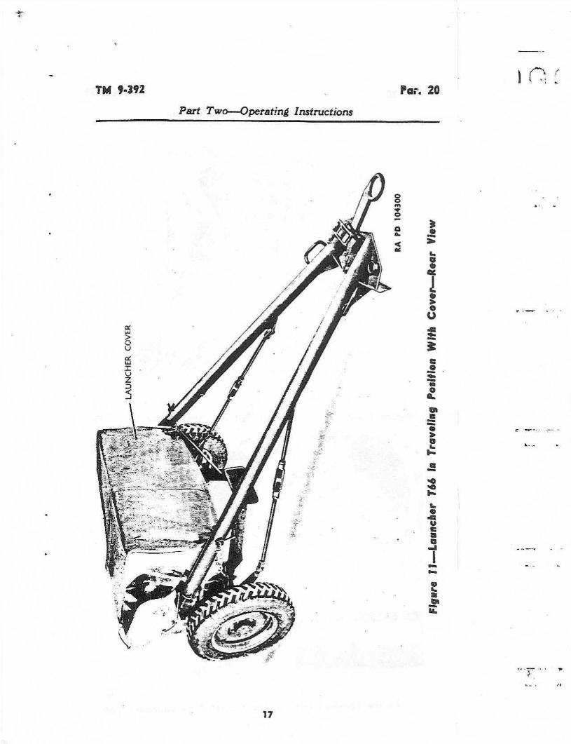
20. TO PLACE LAUNCHER IN FIRING POSITION.a.
Remove launcher cover (fig. 11) and place it out of the way.Select terrain as level as possible on which to emplace the weapon.b.
Unscrew locking bar latches (fig . 12) .
Release firing pedestallocking bars from firing pedestal, and lower pedestal to ground (fig.13).
Place bars in their brackets on the trails .c.
Disengage the trail traveling lock to release the trails (figs. 14and 15).d. Spread the trails and lock them in firing position with thetrail locks (fig. 16) .e.
Tilt the launcher forward (fig . 17) . The firing pedestal willfall into firing position. A click will be heard when the pedestallock engages. Lower trails to ground .16
TM 9-392
Par. 20Part Two-Operating Instructions
mG
a3mwaaa
aati
a
ad
mYCa

Par. 20
Part Two-Operating Instructions
RA P0 104301Figure T2-Releasing Locking Ear Latches an Launcher T66
TM 9 "392
RA FD 104281Figure T3-Releasing Firing Pedestal on Launcher T66

TM 9"392
For. 20
Part Two---Operating Instructions
RA PO 104272
Figure i4-Releasing Trail Traveling Lock on Launcher T66
Tf74 1 ;.. X_ . . .; L ."_" ,= K
LATCH
KIt PB 104302
Figure ?5XReieasing Trail Traveling Lock on Launcher Tf(F2

Par. 20
TM 9-392
Part Two--Operating Instructions
RA PD 104273
Figure 16-Tightening Trail Lock
Figure 17---Tilting Launcher T66
RA PD 104303

TM 9"392
Par. 20
Part Twa-Dperating Instructions
Figure III-Releasing Elevating Lock
Figure t9-.Releasing Traversing Lock996410 0- 52 - 4
21
RA PO 10427'3
TUBECLUSTERTRAVELING
Li1CK
RA ra 704274

Par. 20 "21
Part Two-Operating Instructions
TM 9"392
RA r0 104304
Figure 2a-Cannecting firing Cable to Firing Ilex Socket
f.
Release elevating lock by rotating lock handle counterclock-wise (fig. 18.)
g.
Release traversing lock by rotating lock handle counterclock-wise (fig. 19) .
h. Release tube cluster traveling lock by pulling out the lockhandle and rotating it 90 degrees in either direction (fig. 19) .i.
Install telescope mount and elbow telescope on sight bracket.Adjust cross-leveling screw to center cross-level bubble.j . Connect firing cable to firing box socket . This socket pro-trudes through front panel of the control box (fig . 20) .k.
Fasten antitension clip to eye (fig . 20) .
21.
TO TRAVERSE AND ELEVATE.-a.
Loosen traversing lock and rotate'traversing handwheel clock-wise for left traverse, and counterclockwise far right traverse . Lockin position before firing .
b.
Loosen elevating lock and rotate elevating handwheel. Tightenelevating lock before firing,
22

TM 9-392
Part Twn--aperatind Instructions
Par. 21
Figure 2I-Landing LauncherRA Pa 1042!0
RA Pd 10,305
Figure x2-indexing Indicator an Launcher T6623

Par. 21
Part Two--Qnerating Instructions
Figure 24-Connecting Firing Cable to Blasting Machine(Launcher T6d)
24
TM 9.352
RA PC 10839,6
Figure 23-indexing Indicator on Launcher Tb6E2
RA PD 104307

TEA 9.392
Part Two-Operating Instructions
Figure 25--Connecting Firing Cable to Blasting Machine(Launcher T66E2)
Figure 26-Firing
22. TO LOAD. CAUTION. Before loading, be sure blastingmachine is disconnected from firing cable, Loader should carry handleor preferably entire machine with hint . Set racket fuzes to "DELAY"or "SQ," as desired, and remove safety shorting strip from rockets.Insert rockets into muzzle of each tube, base first. Make sure therocket seats against the stop at the rear of the tube (fig. 2 1) .
25
RA Pa 104309
Par. 22
RA PD 104308

Par. 23
23. TO FIRE.
Part Two---Operating InstructionsInstructions
Figure 27--Releasing Pedestal Lock
a.
Remove telescope mount and place it in control box.
26
0a ra 104310
b.
If desired, index indicator on firing box by pushing button onside of box until the indicator is set on number 1 (figs. 22 and 23) .(When exploder handle is turned, tube No. 1 will fire.)
c.
Make sure all permnnel are approximately 75 feet clear of thelauncher and out of the path of the rocket blast. The person firingshould be off to the side of the launcher, the length of the firing cable.
d. Make sure firing cable is inserted through clip on controlbox so that . it cannot get into path of blast (fig . 20) . An additionalprecaution is made by wrapping the cable several times around thetrail lock handle.
e. Connect firing cable to blasting machine (figs. 24 and 25) .Hold the machine in the left hand, strap across the back of the hand,and insert firing handle.
f. Grasp the firing handle with right hand, knuckles towardsterminals of blasting machine, and twist the handle clockwise asrapidly as possible while twisting the machine in the opposite directionwith the left' hand (fig . 2fi ) .
Since maximum current is generated

TM 9 "392
Pars. 23-25
Part Two---Operating Instructions
only when handle is vigorously twisted all the way to stop, it is neces-sary to "follow through" with each twist. Short weak twists will. notfire rockets, and, generally, will not index switch .
NOTE: One twist of the firing handle will fire one rocket at atime for single fire . For ripple fire, successive twists are necessary.
CAUTION :
If any rocket fails to fire after blasting machine handlehas been twisted, do not approach launcher. Continue to operate blast-ing machine until indicator has again passed rocket . For example,should No. 8 tube fail to fire, operate mechanism until indicator passesthrough No. 24 and then passes No. 8. If rocket still fails to fire, itmust be considered a misfire. Round should then be allowed to remainin launcher at least 2 minutes after last attempt to fire it in order toavoid danger df a hangfrre. After this, the misfired rocket should beremoved from launcher by the loader, other personnel keeping at safedistance. Replace safety shorting strip and remove fuze from rocket .Return the rocket to ordnance personnel for disposition.
24. TO PLACE LAUNCHER IN TRAVELING POSITION.
a.
Remove telescope mount and telescope. With tube cluster indead center of launcher, engage the tube cluster traveling lock.
b. Engage traversing lock.
c. With tube cluster at zero-degree elevation, engage elevatinglock .
d. Tilt launcher forward. Press pedestal lock to release firingpedestal (fig . 27). Push launcher off firing pedestal onto wheels- andlower trails to ground.
e.
Release trail locks, close trails, and engage trail traveling lock.
f. Hook pedestal locking bars to pedestal and tighten up onlocking bar latches.
g. Replace cover.
Section Vill
OPERATION OF AUXILIARY EQUIPMENT
25.
GENERAL.
Operation of on-carriage instruments is describedin section XXVII.
27

Pars. 26-29
TIN 9.392
Part Two--Operatln,6 instructions
26. GENERAL.
Section IX
OPERATION UNDER UNUSUAL CONDITIONS
a. Since rockets may not be fired outside their temperatureranges, operation under extreme temperature conditions is not per-mitted.
b.
Refer to section XII for lubrication under unusual conditions.
27. EXCESSIVELY MOIST OR SALTY ATMOSPHERE.
a.
When the materiel is not in active use, the unpainted metalparts should be covered with a film of rust-preventive compound(light) . The bore -of the metal tubes should be kept oiled and allparts should be inspected daily for traces of the formation of rust.The materiel should be kept covered with tarpaulins as much aspossible.
.
h. In excessively salty atmosphere, the oil or rust-preventivecompound (light) used should be changed often, as the salt has atendency to emulsify the oil and destroy its rust-preventive qualities.
c.
Check carriage frequently for chipped or cracked paint.
28. EXCESSIVELY SANDY OR DUSTY CONDITIONS.
a.
If considerable sand or dust is present when the launchers areoperated, the _lubricant should be removed from the moving partsand these parts should remain dry until the action is over. If thesurfaces are dry, there is less wear than when coated with a lubricantcontaminated with grit
b.
Keep materiel covered with tarpaulins as much as possible.
c. Materiel must be cleaned frequently, as sand .Xr dust andlubricant act as an abrasive .
29. COLD CLIMATES WITHIN TEMPERATURE RANGES.
a.
Preparing a weapon for cold climate consists of inspecting andplacing the launcher in good mechanical condition, cleaning, and lubri-cating with cold-weather lubricants, and frequent exercising .
b.
The materiel should be inspected to see that all moving partsoperate freely and without binding.
c.
In cold climates it is essential that all moving parts be keptabsolutely free of moisture .
28

TM 9-392
Par. 29
Part Two--Operating Instructions
d.
Clean and lubricate all parts, but do not use excess lubricant,because it may solidify to such an extent as to cause sluggish move-ment.
e.
When launchers are in the open, cover with tarpaulins or othersuitable material, if possible.
f.
When tube cluster and carriage are transferred from the out-side into a heated building, wipe dry with clean cloths, and clean andoil metal parts immediately to prevent condensation of moisture .
g. Before applying the cold-weather lubricants, the materielshould be thoroughly cleaned and all old lubricants removed.
h. Tube cleaning.(1)
RIFLE BORE CLEANER. When cleaning the inside of the tubeswith rifle-bore cleaner at temperatures below f) °F, wipe the tubes dryand oil. Do not allow the rifle-bore cleaner to remain in the tubes asfreezing of the cleaner in the tubes may make firing dangerous. Thethird day after firing, use dry-cleaning solvent, if available, to removethe old film . When rifle-bore cleaner can no longer be used due tofreezing, the tubes must either be warmed before continuing to usethe bore cleaner or a soda-ash or soap-solution must be used. Do notadd antifreezes to rifle-bore cleaner.
(2)
SODA-ASH OR SOAP SOLUTION.
When using soda-ash or soapsolution, the cleaning of cold tubes after firing cannot be accomplishedin the normal manner at temperatures below +32 °F. because thewater will freeze in the tubes. If cleaning can be done while the tubesare hot and hot water is available, soda-ash or issue soap solutionwill be used. Otherwise, it will be necessary to add denatured alco-hol, or an emergency substitute (glycerine, or antifreeze compound(ethylene glycol type)) to the solution. To 10 parts by volume ofcleaning solution (water and soda-ash or soap), add the number ofparts of one of the antifreezes indicated below :
(3) In applying light or special preservative lubrication oil tothe tubes after cleaning, work the oil in carefully so that it will reachall surfaces . When the launcher, after being exposed to low tempera-tures, is brought into a heated shop, condensation will occur on allmetal surfaces. After the launcher reaches room temperature, thetubes and all other bright parts must be dried and recoated with oilto prevent rusting.
996410 0 - 52 - 5
29
FOMPcrafurrsIds"s Fl Alcohol or Wycorlwo or AefiTreoze Compound
20 2 2y210 4 5 3 1/30 51/2 51A 5
-15 9 10 7 1/4-30 16 13 10_4(? 27 15 12

Pars. 29 "31
TM 9-392
Part Two--Operating Instructions
(4) After firing, the tubes will be cleaned with bore cleaningsolution on 3 consecutive days thereafter, or longer if sweating con-tinues, then dried. and oiled.
(5) During periods when the materiel is not fired, the oil filmwill be renewed daily by swabbing with burlap saturated with oil.Every 5 days, swab with dry-cleaning solvent, dry, and renew the oilfilm .
30. HOT CLIMATE WITHIN TEMPERATURE RANGES.
a.
In hot climates, inspect and clean the launcher as frequentlyas required, rather than at fixed intervals .
h.
Where humidity is high, clean and oil as soon as possible afterfiring, when the launcher gets wet or dirty, or if there is any reasonto expect corrosion to start.c. In temperatures above 90"F, summer grade greases and oils
should be used as lubricants .
Section X
DEMOLITION TO PREVENT ENEMY USE
31. GENERAL.a. The destruction of the materiel when subject to capture or
abandonment in the combat zone will be undertaken by the usingarm, only on authority delegated by the division or higher commanderas a command function when such action is deemed necessary as afinal resort to keep the materiel from reaching enemy hands.b. Adequate destruction of artillery materiel means damaging
it in such a way that the enemy cannot restore it to usable condition,in the combat zone either by repair or by cannibalization. Adequatedestruction requires that :
(1)
Enough parts essential to the operation of the materiel mustbe damaged.
(2)
Parts must be damaged beyond repair in the combat zone.(3)
The same parts must be destroyed on all materiel, so thatthe enemy cannot make up one operating unit by assembling partsfrom several partly destroyed units.
c.
The tubes are the most vital parts of these weapons. Theseare the first things to damage .
30
TM 9.392
Pars. 32-33
Part Two---Operating Instructions
32. DEMOLITION OF LAUNCHERS T66 AND T66E2.a.
Detach the sight, If evacuation is possible, carry the sight. If.got, smash the sight thoroughly.
b,
Insert one incendiary grenade M14 midway in the center tubeat zero-degree elevation. Ignite this grenade by inserting one othergrenade, equipped with a 15-second safety fuze . Take cover, as thedanger zone is at least 100 yards.
33. DEMOLITION OF AMiUUNITION. Demolition of ammuni-tion is covered in TM 9-1901.

Pars. 34-36
TM 9-392
PART THREE--MAINTENANCE INSTRUCTIONS
36. LUBRICATION ORDER.
Section Xl
GENERAL
34. SCOPE. Part Three contains information for the guidanceof the personnel of the using organizations responsible for the main-tenance (first- and second-echelon) of this equipment. It containsinformation needed for the performance of the scheduled lubricationand preventive maintenance services as well, as a description of themajor systems and units and their functions in relation to other com-ponents of the equipment.
35 .
CLEANING AND PRESERVING MATERIALS.
The follow-ing cleaners and preservatives are issued for use with this materiel(see SNL K-1 and TM 9-850 for detailed information.)BURLAP, juteCLEANER, rifle-boreCLOTH, crocusCLOTH, wiping, cottonGREASE, O.D.OIL, engineOIL, preservative lubricating (special)SODA-ASHSOLVENT, dry-cleaning
Section X11
LUBRICATION
a.
Reproduction of War Department Lubrication Order LO 9-392(fig . 28) prescribes first- and second-echelon lubrication maintenance.h.
The lubricating fittings indicated on the order are illustratedin figures 29 to 33, showing their location on the materiel . Thefittings shown in the figures may be identified on the order by thekey numbers around the border.c. A lubrication order (formerly War Department Lubrication
Guide) is placed on or is issued with each item of materiel and is to
Figure 28-War Department Lubrication Order LO 9-392(to be inserted when airaiiabie)
32

TM 9"392
Fi9X+re 2g,--Lvbgcvf,Qn Foinf No. I
Figure20~'LubricofiorrPoint
: No RA rs 744312X" Z an d33 X
RA ft 1a4377

Part Three-Maintenance Instructions
Figure 31---Lubrication Paints Has. 4 to 10 Inclusive
TIN 9-392
RA PD 10{313
be carried with it at all tunes. In the event the materiel is receivedwithout an order, a replacement should be immediately requisitioned(FM 21-6) .
37. GENERAL LUBRICATION INSTRUCTIONS.
a. Lubricants. Lubricants are prescribed in the "Key" on theLubrication Order in accordance with three temperature ranges"above +32 ° F,� "from x-32° F to 0' F," and "below Q° F." The time
34

TM 9-392
Par. 37
Part Three Maintenance Instructions
RA PD 164314
Figure 32-Lubrication Points Nos. )1 to 15 lnciusive35

Par . 37
Part Three--Maintenance Instructions
36
Figure 33--Lubrication Points Mos. 16 and 17
TM 9"392
" PO 1"315
to change grades of lubricants is determined by maintaining a closecheck on operation of the materiel during the approach to prolongedperiods when temperatures will be consistently in higher or lowerranges . Because of the time element involved in preparing for opera-tion at lower prevailing temperatures, a change to lubricants pre-scribed for a lower range will be undertaken the moment operationbecomes sluggish. Ordinarily, it will be necessary to change lubricantsonly when expected air temperatures will be consistently in the nexthigher or lower range, unless malfunctioning occurs sooner due tolubricants being of improper consistency. NOTE : Seasonal changesof lubricants and recoil oils will be recorded in the Artillery Gun Bookb.
Service intervals.
Service intervals specified are for normaloperating conditions and continuous use of the materiel with frequentfiring. Reduce these intervals under extreme conditions such as ex-cessively high or low temperatures, prolonged periods of traveling orfiring, continued operation in sand or dust, immersion in water, orexposure to moisture. Any one of these conditions may quicklydestroy the protective qualities of the lubricant, and require servicingin order to prevent malfunctioning or damage to the materiel.
c. Lubricating equipment.(1)
Be sure to clean lubricating equipment both before and afteruse. Operate lubricating guns carefully and in such manner as to

TM 9-392
insure proper distribution of the lubricant.
If lubrication fitting valvesstick and prevent the entrance of lubricant, remove the fitting anddetermine cause. Replace broken or damaged lubricators. If lubri-cator cannot be replaced immediately, cover hole with tape as atemporary expedient to prevent the entrance of dirt . If oil lines becomeclogged, disassemble the line and remove the obstruction.
(2)
Lubrication fittings, grease cups, oilers, oil holes, and plugsare circled in red for ready identification .
(3) Wipe lubricators and surrounding surfaces clean before ap-plying lubricant. Where relief valves are provided, apply newlubricant until the old lubricant is forced from the vent . Exceptionsare specified in notes or on the Lubrication Order. Metal surfaceson which a film of lubricant must be maintained by manual applica-tion, will always be wiped clean before the film is renewed.
d. Cleaning .(1) Unless otherwise specified, use rifle-bore cleaner or dry-
cleaning solvent to clean or wash all metal parts, whenever partial ortotal disassembly is undertaken, or when renewing the protectivelubricant film on exposed metal surfaces. Flushing of gear casesand bearing housings will not be undertaken unless inclosed mecha-nism is first disassembled in order to insure complete removal of thecleaner or solvent prior to the application of lubricants. Use of gaso-line for cleaning is prohibited. Dry all parts thoroughly beforelubricating.
(2)
Care must be taken when cleaning oil and grease compart-ments to insure the complete removal of all residue or sedimentDirt or other foreign matter should not be allowed to drop into any ofthe lubricating compartments.
e. Lubrication.
Part Three Maintenance Instructions
(1) Fill elevating and traversing mechanisms with O.D. greaseNo. 0 above +32° F or No. 00 below +32° F, monthly.
(2)
The wheel bearings should be removed at 6-month intervalsfor lubrication with general purpose grease No. 2.
(3) Lubricate other bearings equipped with lubrication fittingswith O.D. grease No. 0 above +32'F or No. 00 below +32' F,monthly.
(4)
Clean all unpainted metal surfaces, latches, and linkages ofthe carriage daily, and oil with engine oil SAE 30 above +32' F orSAE 10 between 32' F and 0"F, or preservative lubricating oil.(special) below 0° F.988410 0 - 52 - 6 37
Par. 37

Pars . 38 "39
TM 9-392
Part Three-Mainteriance Instructions
38. GENERAL.
Section X111
PREVENTIVE MAINTENANCE SERVICE
a.
Scope.
Preventive maintenance services prescribed by ArmyRegulations are a function of using-organization echelons of main-tenance. This section contains preventive maintenance service allo-cated to crew and scheduled preventive maintenance service allocatedto (second echelon) organizational maintenance.
b.
Cleanliness.
Dirt or grit, accumulated in traveling or fromblast of piece in firing, settles on bearing surfaces and forms a cuttingcompound. Powder fouling attracts moisture and settles in operatinggrooves, preventing proper operation of moving parts, and hastensthe formation of rust It is essential that all parts be cleaned at fre-quent intervals, depending upon use and service.
c.
Rust removal.
If rust should accumulate, its removal frombearing surfaces requires special care in order that clearance shallnot be unduly increased .
Crocus cloth should be used for this purpose.The use of coarse abrasives is strictly forbidden.
d.
Care.
When materiel is not in use, suitable tarpaulins shouldbe used as covers . When materiel is not to be used for considerabletime, all bright unpainted metal surfaces should be cleaned with dry-cleaning solvent and coated with rust-preventive compound.
39. PREVENTIVE MAINTENANCE SCHEDULES.
a. Before firing .Point
Prer"fre MQinteaeac=
Tube cluster
Clean and dry.b. After firing.
Tube cluster
Clean and oil.
Par. 37 dFiring cable
Clean.
Par. 42 fa
d. If used in wet weather.Contact fingers
Dry.and exposed wires
Par. 42 d38
detailodInstructions a
Par. 42 a
c. . Daily service.Tube cluster
Clean and oil.
Par. 42 c

TM 9-391
Pair. 48
Part Three Maintenance Instructions
Section XIV
MALFUNCTIONS AND CORRECTIONS
40. FAILURE TO FIRE.
a.
Contacts may become rusted or corroded . Clean them withcrocus cloth.
b. Live contact is insulated from tube by air space. Shouldthese contacts be damaged so that they touch the tubes contact willbe shorted and rocket will not fire . The contacts may be adjusted bybending them slightly up or down. Contact may be replaced com-pletely using the wrench provided .
c.
If couplings on firing cable are damaged or broken, a temporaryrepair may be made until the ordnance maintenance personnel arenotified .
d.
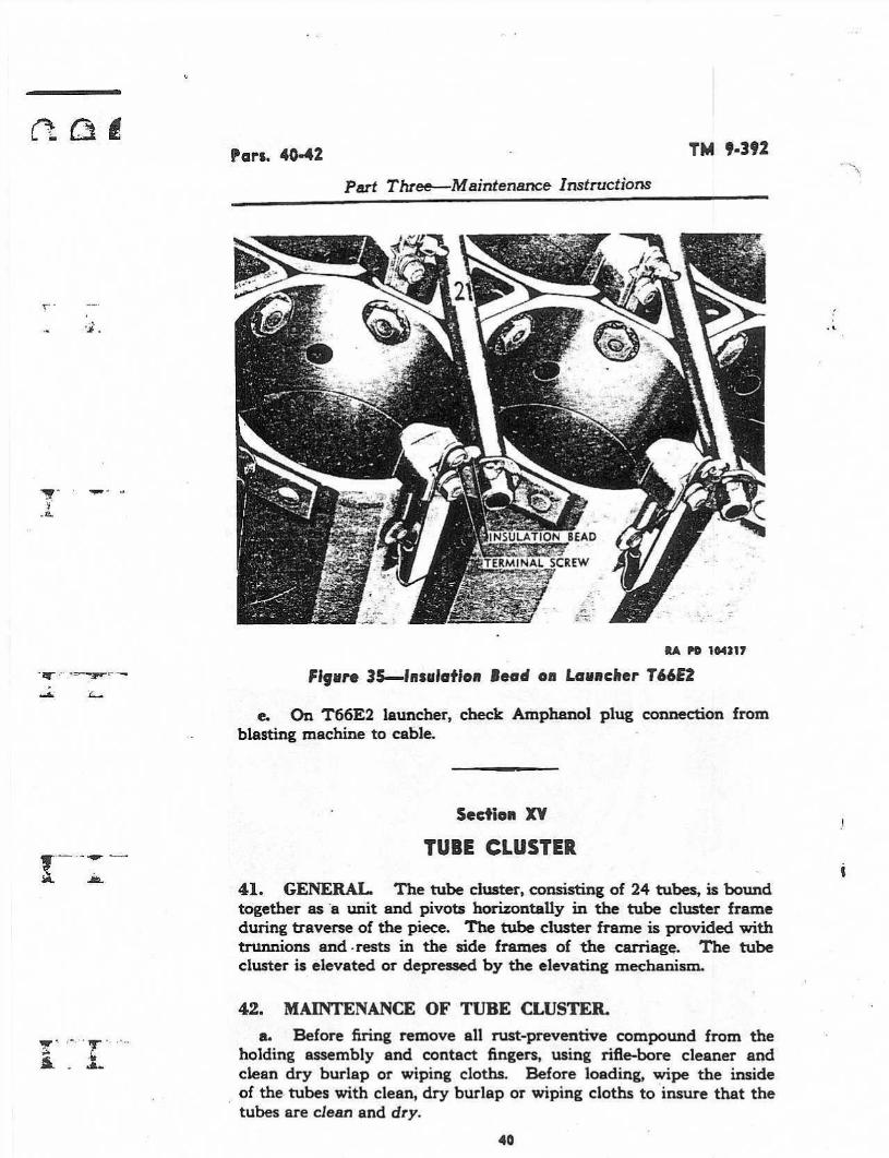
Check the insulation bead on the wires. If damaged, removeterminal screw, remove damaged bead, and insert new one, thenreplace terminal screw (figs. 34 and 35) .
Figure 34-Insulation Bead on Launcher T66
39
KA PD 10431,6
Pars. 40-42
Part Three Maintenance Instructions
TM 9-393
*w PO 144317
Figure 3S-insulation Bead an Launcher Tb6E2
e.
On Tfi6E2 launcher, check Amphanol plug connection fromblasting machine to cable.
Seetian XV
TUBE CLUSTER
41 .
GENERAL.
The tube cluster, consisting of 24 tubes, is boundtogether as -a unit and pivots horizontally in the tube cluster frameduring traverse of the piece. The tube cluster frame is provided withtrunnions and .rests in the side frames o£ the carriage .
The tubecluster is elevated or depressed by the elevating mechanism.
42. MAINTENANCE OF TUBE CLUSTER.
a. Before firing remove all rust-preventive compound from theholding assembly and contact fingers, using rifle-bore cleaner andclean dry burlap or wiping cloths . Before loading, wipe the insideof the tubes with clean, dry burlap or wiping cloths to insure that thetubes are clean and dry.

TM 9"392
Part Three Maintenance Instructions
Par. 42
b.
After firing, clean and oil the inside of the tubes as prescribedin paragraph 37 d.
c.
When not being fired, wipe tubes clean daily and renew the oilfilm. To remove gummy deposits of congealed oil, swab with dry-cleaning solvent, wipe thoroughly dry, and reoil. A cleaning staffis issued with the launcher .
d.
If the launcher has been used in wet weather, dry all electriccontact points and exposed wires with a dry cloth. Clean and oil therest of the launcher as described above.
e.
After firing, wipe the firing cable clean of any dirt, grease, orforeign material, using clean, dry burlap or wiping cloths.
f. Bore cleaning and preservation. The following materialsand cleaning and preserving procedures will be used for the insideof the tubes in order of indicated preference . Oils to be applied aftercleaning will be the same as prescribed by applicable War Depart-ment Lubrication Orders and Technical Manuals for specific tern-perature ranges.
1)
RIFLE-SORE CLEANER(a) After firing, and on two consecutive days thereafter, thor-
oughly clean the inside of the tubes with rifle-bore cleaner making surethat all surfaces are well coated. Do not wipe dry.(b)
On the third day after firing, clean the inside of the tubeswith rifle-bore cleaner. If the piece will probably be fired within thenext 24 hours, do not wipe dry. If the piece will not be fired within thenext 24 hours, wipe dry and coat with the prescribed oil.
(c) After the third day since firing, renew the oil film daily.Every fifth day, clean with rifle-bore cleaner, wipe dry, and reoil.
SODA-ASH.(a)
Prepare a solution of one-half pound soda-ash to each gallonof warm water. In temperatures below +32'F, add the type andamount of antifreeze prescribed in TM 9-850, if the tubes to be cleanedare cold.(b)
Immediately after firing and on three consecutive days there-after, thoroughly clean the tubes with the soda-ash solution. Rinsewith clean warm water and wipe dry. Coat with the prescribed oil.
(c) When the piece is not being tired, renew the oil film daily.Every fifth day, clean the tubes with dry-cleaning solvent or rifle-borecleaner, if available.
Wipe dry and reoil.(3) SOAP.(a)
Use castile soap or issue soap.(b) Prepare a sponging solution by shaving one pound of soap
into four gallons of water. If possible, warm the water to facilitatedissolving the soap.
In temperatures below +32' F, add the type

Pan. 42-43
TM 9-392
Part Three--Maintenance Instructions
and amount of antifreeze prescribed in TM 9-850, if the tube to becleaned is cold .
(c) Follow the same cleaning, drying, and oiling procedure pre-scribed for the soda-ash solution.CAUTION : When issue soap is used, the tubes must be thoroughly
rinsed after cleaning as the soap may contain free caustic which willcause corrosion if it is not completely removed.
(4)
HoT WATER.
(a)
As a tempbrary measure after firing, the tubes may be cleanedwhile still hot by swabbing with quantities of hot water. This methodwill be used only when rifle-bore cleaner, soda-ash, or soap are notavailable. Extreme care must be taken to thoroughly dry the tubesafter cleaning with hot water. A coating of oil will be applied imme-diately thereafter, to prevent rusting.
(b)
Swabbing with hot water may not remove all of the primersalts or powder residue. It is most important, therefore, that the tubesbe cleaned as soon as possible in accordance with paragraph 37 apby or c.
43. GENERAL.
FIRING MECHANISM
a.
The firing mechanism is a ten-cap blasting machine (fig . 9) .It is used as a source of electricity for firing the rocket from thelaunchers T66 and T66E2.b.
This machine is a small portable dynamo or magneto whichweighs about five pounds. Two terminals are located on the uppersurface of the body of the exploder. The exploder is operated bytwisting the handle . The quicker the twist, the more current gener-ated The firing handle of this machine is removable. It should bedetached from the machine until the rockets are ready to be fired.
c.
The exploder can be connected to the firing box by the de-tachable firing cable which leads to the firing box tan the T66E2launcher, the Amphanol plug connection is made) (fig . 20) . Prior
42

TM 9 "392
Part Three-Maintenance Instructions
(Do(:X
s 000(:)C8s
:
9
11
13
15
10
1(
Z 14)
1s
lT i9 Zl Z3 18 ZQ ZZ C24
4-4 . MAINTENANCE OF FIRING MECHANISM.
'ears. 43-45
RA Pa 104276
Figure 36--Firing Order of Tubes--Tube ClusferRear View
to firing, the box may be indexed to starting position (or any otherposition desired) by manually pushing button on side of box (withthe blasting machine disconnected) . The indicator may be usedas a counter and as an indication of the tubes to be fired by setting thedial to No. 1 . Each time the blasting machine is operated to fire arocket, the indicator moves one position on the dial. The firing orderof the tubes in the cluster is indicated in figure 36 .
a .
If the voltage weakens through lack of use, connect the termi-nals with a short piece of wire and twist the firing handle vigorouslyseveral times. Then remove the short piece of wire,
b.
These exploders are issued with the launcher . They are alsoissued by the engineers, and replacements may be obtained fromthem if not otherwise available . Exploders should be returned toengineer personnel for adjustment and repair . Prior to turning inblasting machine from Tfi6E2 launcher for replacement, the cableconnection with Amphanoi plug should be removed.
Section XVl1
CARRIAGE
45.
GENERAL.
The carriage is a welded unit, consisting of twoside frames welded to an axle which supports the wheel spindles . Theside frames support the tube cluster frame.
43

Pars. 46-49
. .
TN! 9.392
Part Three Maintenance Instructions
46. MAINTENANCE OF CARRIAGE. Maintenance of the car-riage consists of lubricating latches and linkages, and lubricating allpoints equipped with lubricating fittings (see section XII) .
Section XV111
TRAILS AND TIE RODS
47. GENERAL. The trails of the T66 launcher are welded as-semblies which consist of the trail body, spades, and lunette. Thetrails of the T66E2 launcher are welded assemblies consisting of thetrail body and spades . A detachable lunette is provided at the spadeend of the trails. The trails of both launchers are hinged to the car-riage side frames. Trail locks are located on the sides of the carriage .A trail traveling lock is provided an the back end of the trails . Tierods, which are provided to support the trails, are fastened to themiddle portion of the trails and to brackets on the axle of the carriage(fig. 3) .
48. MAINTENANCE OF THE TRAILS AND TIE RODS.a.
If the lunette on the T66E2 launcher is damaged, it may bereplaced.
b.
The tie rods are to be kept tight by means of the turnbuckles,should they become loose. Looseness of the tie rods adversely affectsstability of the launchers when fired at maximum traverse.
Section XIX
CONTROL Box49.
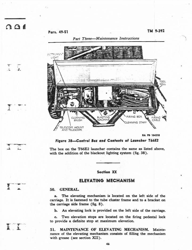
GENERAL. The control box on bath launchers is fastened onthe rear portion of the tube cluster (figs. 1 and 2) . The box on theT66 launcher contains the ten-cap blasting machine, firing handle,firing box, firing cable, telescope mount with elbow telescope, instru-ment .light, cleaning brush and staff, tool kit, and spare parts (fig. 37) .
44

TM 9-392
Par. 49
Part Three----Afacntenance Instructions
ut
T
J
aOLO .
W
PANfOait
a
ap.cD
veD
Pars. 49-51
TAIL 9-392
Part Three-Maintenance Instructions
1j TELESCOPE MOUNT'
AND TELESCOPE
5©. GENERAL.
Figure 38--Controf Box and Contents of Launcher T56EZ
The box on the T66E2 launcher contains the same as listed above,with the addition of the blackout lighting system (fig . 38) .
Section X7[
FII`ING BOX
ELEVATING MECHANISM
CLEANING STAFF
FIRINGCABLE
RA PD 10431B
a. The elevating mechanism is located on the left side of thecarriage. It is fastened to the tube cluster frame and to a bracket onthe carriage side frame (fig. 8) .
b.
An elevating lack is provided on the left side of the carriage.
c. Two elevation stops are located on the firing pedestal lockto provide a definite stop at maximum elevation.
ail. MAINTENANCE OF ELEVATING MECHANISM. Mainte-nance of the elevating mechanism consists of filling the mechanismwith grease (see section XII) .
46

TM 9"392
52. GENERAL.
Part Three Maintenance Instructions
Section XXI
TRAVERSING MECHANISM
a.
The traversing mechanism is located on the left side of thecarriage. It is fastened to the tube cluster frame and tube clusterunit (fig. 8) .
h.
Atraversing lock is provided on top of the tube cluster frame.
53. MAINTENANCE OF THE TRAVERSING MECHANISM.Maintenance of the traversing mechanism consists of filling themechanism with grease (see section XII) .
Section XXII
FIRING PEDESTAL
Pars. 52 "56
54. GENERAL. The firing pedestal is a welded assembly . Thepedestal is dropped to the ground for firing position and is lockedin place (fig . 5). The pedestal is held in traveling position by lockingbars.
Section XXIII
SIGHT BRACKET
55.
GENERAL.
The sight bracket is bolted to the front left cornerof the tube cluster (fig. 8) . A cross-leveling screw is located to theright of the bracket for use in maintaining the telescope mountvertical .
Section XXIV
WHEELS
56.
GENERAL.
The wheels are of commercial type and mount a6.00 x 16 tire. These wheels are directly interchangeable with thoseused on jeeps.
47

Per. 5a
TAB 51-392
Part Thre&-Maintenance instructions
57. MAINTENANCE OF WHEELS .a. There is no provision for adjustment of camber, caster, or
toe-in on the axle.h. Pack the wheel bearings with grease, as prescribed on the
Lubrication Order (fig. 28) .
c.
Special attention should be given to keeping the wheel studnuts tight.

2
TM 9.392
Pars. 50-59
eI
.S
ne
PART FOUR---AUXILIARY Eq)UIPMENT
section XXY
GENERAL
58.
SCOPE.
Part Four contains information for the guidance ofthe personnel responsible for the operation of this equipment. It con-
tains only the information necessary to using personnel to properly
identify, connect, and protect such auxiliary equipment while being
used or transported with the main equipment. Detailed instructionspertaining to auxiliary equipment are contained in pertinent Tech-nical Manuals.
59. DESCRIPTION.
Section XXYI
AMMUNITION
a.
General.
Rocket ammunition for the multiple launcher T66and T66E2 is issued in the form of unfuzed complete rounds (fig . 39),except the smoke rocket which is issued fuzed. The rocket is acylindrical projectile with an agival nose and square base. It is pro-pelled by reaction to a jet of gas produced within the rocket itselfand ejected through a number of nozzles in the base . The nozzlesare directed at an angle so as to impart spin as well as thrust, thusfurnishing the rocket with a means of stabilization similar to that ofan artillery shell.
b. Types. Dependent upon the filler, these rockets are classi-fied as high-explosive, smoke, and practice. . The high-explosive rocketis loaded with a bursting charge of TNT and is equipped with apoint-detonating fuze and booster. The smoke rocket is loaded withphosphorus and equipped with a point-detonating fuze and a burster.The practice rocket is loaded with inert material and equipped witha dummy fuze.
c. Components . The complete round (fig. 40) consists of aloaded shell with fuze and booster or burster and a motor containingthe propelling charge and an electric igniter. The igniter lead wirespass through one of the nozzles; one is grounded to the rocket body,the other is connected to the contact ring on the closing cup.
49

Par. 59
TM 9.392
Part Four-Auxiliary Equipment
mNM6
di
K
Q1
Vaacw
0%MraIM

Part Four--Auxiliary Equipment
Par. 59

60. IDENTIFICATION .
61. AUTHORIZED ROUNDS.
Part Four--Auxiliary Equipment
TM 9.392
a,
General.
In common with other types of ammunition, rockets
are identified by means of the painting and marking on the item and
its packings. Positive identification consists of the standard nomencla-
ture of the item and its ammunition lot number.
b.
Painting.
Ammunition is painted to prevent rust and to pro-
vide, by the color, a means of identification as to type..
(1) RocxET SHELL :High-explosive . . . . . . . Olive drab, rnarkirrg in yellowSmoke . . . . . . . . . . . . .Gray, one band and marking all in "yellowPractice
. . . . . . . . . . . . Blue, marking in white
(2)
RocKET moToRs. Since motors for all types of rockets con-tain full service charge, they are painted olive drab and marked inyellow .
c. Marking. Marking stenciled on the rocket includes type,caliber, model, lot number, loaders initials, date loaded, and safetemperature limits.
d. Standard nomenclature. Standard nomenclature is estab-lished in order that each item may be specifically identified by name.It consists of the name, type, size, and model designation. The modeldesignation is assigned when the item is standardized; it consists ofthe letter M and an arabic numeral- Modifications of the original de-sign are designated by the addition of the letter A and the appropriatenumeral; for example, M6A3 indicates the third modification of anitem originally adopted as M6. When a modification is of a temporarynature or does not supersede the basic *aodel, it is indicated by addinga letter : M6A3D. Standard nomenclature of rockets is published inASF Catalog, ORD 11 SNL S-9.
e.
Ammunition lot number.
Atot of ammunition consists of anumber of items, manufactured under uniform conditions from uni-form materials, which are expected to function uniformly. The lotnumber identifies each individual lot of ammunition and is requiredfor all purposes of record making - reference to particular items ofammunition.
a.
List of rounds.
The rockets authorized for firing from theselaunchers and specific data are listed in Table 1 .
52

TM 4"392
Fars. 61-62
Part Four-Auxiliary Equipment
TABLE I
lFuze, Pb, M81 consists of body of fuze PD M48A2 and booster M24. Fuze, PI), M48A2with booster M21AI, may be substituted.,ISupplementary charge roust be removed from fuse well when *+s fuse is used .
h, General data. All rackets of this type are designed to beballistically interchangeable; data common to the type are givenin table 2.
TABLE 2
Range maximum . . . . . . . . . . . . . . . . . . . . . . . . . . . . . . . . . . . . 5,200 ydDispersion . . .
. . . . . . . . . . . . . . . . . . . . . . . . . . . . . . . . . . . . . 9 milsVelocity mar. . . . . . . . . . . . . . . . . . . . . . . . . . . . . . . . . . . . . . . . 990 ft per secSafe temperature iirnita . . . . . . . . . . . . . . . . . . . . . . . . . . . . . . . -20° to x-130 ° FBurning time, . . . . . . . . . . . . . . . . . . . . . . . . . . . . . . . . . . . . . . 4.36 to 0.10 secBurn out point . . . . . . . . . . . . . . . . . . . . . . . . . . . . . . . . . . . . . . 80 ft froxn launcherWeight fuzed . . . . . . . . . . . . . . . . . . . . . . . . . ., . . . . . . . . . . . . 42.5 fb
c. Differences in models. The various models and modifica-tions differ as follows :
(1)
HE ROCKET M16. This is the parent model described above.It is adapted for standard artillery-type fuzes.
(2)
HERocK= T38E2. This model is similar to the M16 exceptthat it has a deep fuze well for accommodation of special fuzes.
(3) HE 12UCSET T38E8. This model is similar to the T38E2except that the deep fuze well contains a removable supplementarycharge. With this charge in place, standard fuzes may be used; byremoving the supplementary charge, special fuzes may be used.
(4)
SMOKE ROCKET T84.
The shell of this model does not havethe burster tube extending into the motor, as does the HE shell. In-stead, the shell body is slightly longer.
(5)
PRAcd'ICE Rom= M17. This rocket is similar to the HErocket M16 except that the shell filler is inert.
62. PREPARATION FOR FIRING.
a. In order to prepare the rocket for firing, it is necessary toremove the packing, to fuze the round as described below, and toremove the safety shorting strip and tape from the contact rings. Ifthe rocket is not fired, the safety shorting strip should be replaced,the round defuzed, and all components returned to their originalcondition and packings.
53
ROCKET ModelFUZE
AcfiionLENGTHFUZEDiinlia .I
ROCKET, HE, 4.5", M16 mall SQ, 0.05-sec delay 31ROCKET, HE, 4.5", T38E2 T31 VT 31ROCKET, HE, 4.5", T38E8 T32 SQ' 0.Q5- delay 31
ROCKET, smoke, WP, 4.5", T84 T36E1 SQ 33ROCKET, practice, 4.5", M17 T73 Isurnrny 31

Pars . 62-63
Part Four-Auxiliary Equipment
b.
Fuzing with standard fuzes.
TM 9-392
(1)
Remove rocket from packings and inspect to see that basesealing disk is in place. If the disk is loose, it may be replaced andthe rocket used, provided it can be ascertained that no moisture orother foreign material has entered the motor.
(2)
Remove fuze from packings and inspect to insure there is nocorrosion and that there are no damaged threads. Set the fuze (fig. 41)for desired action, superquick or delay, by turning the setting sleeveacross the axis of the fuze, or delay, or parallel to the fuze axis, forsuperquick action .
(3) Loosen set screw in adapter and remove shipping plug.Inspect fuze cavity for presence of foreign material and damagedthreads. When fuzing T38E8, be sure supplementary charge is present.
(4)
Screw fuze into place and tighten with fuze wrench. Tightenset screw in adapter.
.
c.
Fuzing with VT fuzes.
Fuzing the T38E2 or T38ES withspecial fuzes is essentially the same as the procedure for standardfuzes described above except that the supplementary charge, whenpresent, must be removed. When special action is necessary, direc-tions will be packed with the fuzes.
63. PRECAUTIONS IN HANDLING.
a.
Rockets are packed to withstand conditions usually encoun-tered in the field. However, since ammunition is adversely affectedby heat, shock, and moisture, due consideration should be given thefollowing
(1) Packings should not be opened in advance of anticipatedneeds and items prepared for firing but not used should be restoredto their original packings and resealed.
(2)
Ammunition should be handled with care at all times. Pack-ings should not be tumbled or dropped. Damaged packings should berepaired or replaced with due care given to transferring all markings .
(3)
Rockets and fuzes are particularly sensitive to heat and shouldbe protected against all sources of excessive heat, such as the directrays of the sun. If it is necessary to store such items in the open,piles should be placed on dunnage and covered with paulins arrangedso that air can circulate freely through all parts of the stack.
b. Rockets must not be fired at temperatures outside the safetemperatures marked on the rocket. Firing at temperatures belowthose specified will result in erratic ranges ; firing at temperatures abovethe safe range will result in dangerous pressures being built up in therocket motor.
c.
Rockets with dented bodies, damaged fuze threads, or missing54

TM 9 "392
Far. 63
Part Four-Auxiliary Equipment
Figure 41-Fuze M8135
itA IAA &3211

Par. 63
Part Four-Auxiliary Equipment
Figure 42--Packing:56
TM 9-392
RA PC 103581

TM 9-392
Pars. 63-65
Part Four-Auxiliary Equipment
base closing disks should not be used. If the closing disk is loose, itmay be replaced, provided it can be ascertained that no moisture orother foreign material has entered the motor.
d. Fuzes with damaged threads and those showing substantialamounts of corrosion should not be used.
e.
When a rocket is fired, the blast of flame extends to the rearapproximately 75 feet . Personnel and materiel should be kept clearof this area from the time the launcher is loaded until after the rocketis fired. If practicable, inflammable material such as dry vegetationshould be cleared from this area before firing.
f.
Care should be exercised to protect the rocket against strayelectric currents . If a rocket is accidentally ignited it takes off withfull service velocity . The safety shorting strip should be in place acrossthe contact rings at all times except when the rocket is in the launcher.
64. PACKING.
a.
Rockets are packed with a shipping plug in place of the fuzein individual fiber containers which, in turn, are packed in metalcontainers (fig . 42) or wooden boxes.
Fuzes are packed in individualsealed containers which are packed in wooden boxes.
b.
While dimensions and weights may vary, dependent upon thepacking, the following data may be taken as representative for thepurpose of making estimates. Complete packing and shipping dataare published as soon as available in ORD 11 SNL S-9.
1"sm
Packed
ROCKET, HE, 4.5"MI6
1/fbr cntr 1/mti cntr
371/a x 61/a diam
1 .8FUZE, PD, M46A2, S4-
1/can 1S/box
163/4 x 93/4 x 9
0.8
50.05-sec delay w/boaster MZIAI
Section XXYI1
SIGHTING AND FIRE CONTROL EQUIPMENT
65. GENERAL. This section contains information on the ar-rangement of the sighting equipment It includes instructions foroperation and maintenance of each item of on-carriage equipment.Instructions covering off-carriage equipment are not included in thissection, but a list of this equipment is contained in paragraph 6. Theoff-carriage equipment is covered in other Technical Manuals (sec.XXIX) .
57
Dimensions
wt(inches)
Cm R
{ibl

Par. bbPart Four--Auxiliary Equipment
66. ARRANGEMENT AND USE.
58
-CLAV.P SCREW
BLB0G";' TELESCDFE Mr5Z(IN OPERATING POSITION)
TM 9-392
RA Pa 102781
Figure 43-Sightunif T128E1-Mounted on 4.5-inch MultipleRocket Launcher
a.
The sighting equipment is designed for direct or indirect fire .
b.
Any one of the following equipment groups may be furnishedwith the launcher
(1)
SIGHTUNIT T128E 1 (fig . 43) .
The sightunit includes thetelescope mount T148E 1 which supports the telescope adapter M9 andelbow telescope M62 . The telescope mount is used for setting eleva-tion, the telescope adapter is used for setting azimuth, and the elbowtelescope is used far sighting on the target or aiming point. Thisequipment is secured together as a unit and is not to be separated bythe using arm personnel.
(2) SIGHTUNIT T 12 7E 1 . The sightunit T12781 includes the ele-vation quadrant T13E5 which supports the telescope adapter M9 andelbow telescope M62. This equipment is identical with sightunitT128E 1 except for the elevation quadrant T1385, which is a light-weight version of the telescope mount T148E 1 .
(3)
TELESCOPE MOUNT T72E 1 WITH ELBOW TELESCOPE M62(fig . 44) . The telescope mount T72E1 supports the elbow telescopeM62 . The two instruments are not to be separated by the using arm

TM 9.392
/V',ATCHiNG LINES
TELESCOPE MOUNT T-LE i
HAND LIGHTMUZZLE END :OF LAUNCHER1
Part Four-Auxiliary Equipment
Pars. 66-67
ELSOw TELESCOPE M62(IN OPERATING POSrrrON ;
RA Pb 182787Figure 44-Telescope Mount T72EI With Elbow Telescope M62XMounted on Racket Launcherpersonnel. The mount includes scales for setting elevation anddeflection.
67. MAINTENANCE.a. Care in handling sighting and fire control instruments.(1)
Sighting and fire control instruments are, in general, ruggedand suited for the designed purpose. They will not, however, standrough handling or abuse. Inaccuracy or malfunctioning will resultfrom mistreatment.(2) Unnecessary turning of screws, or other parts not incidentto the use of the instrument, is forbidden.(3)
Stops are provided on instruments to limit the travel of themoving parts. Do not attempt to force the rotation of any knob be-yond the stop limit,(4)
When not in use, keep the instruments in the bracket in thecontrol box of the launcher, or covered and protected from dust andmoisture.(5)
Keep the instruments as dry as possible .
If an instrument iswet, dry it carefully before placing it in the control box.59

Par. 67
Part Four-Auxiliary Equipment
TM 9-392
(6)
Any instrument which indicates incorrectly or fails to func-tion properly is to be turned in for repair by ordnance maintenancepersonnel.
(7) No painting of sighting or fire control equipment by theusing arm personnel is permitted.
(8) When disengaging the azimuth mechanism of telescopeadapter M9 (on sightunit T127E1 and sightunit T128E1), push theazimuth knob outward as far as it will go to be sure that the internalworm and worm gear are completely disengaged. Do not allow theworm to drag over the worm gear teeth as this will result in unneces-sary wear of the parts.
(9)
Clamping screws must not be tightened beyond a snug con-tact. Excessive wear of threads and other damage to the instrumentare thereby eliminated.
la.
Optical parts.(1)
To obtain satisfactory vision, it is necessaty that the exposedsurfaces of the lenses and other parts be kept clean and dry. Cor-rosion and etching of the surface of the glass, which interfere withvision, can be prevented or greatly retarded by keeping the glassclean and dry.
(2) Cinder no circumstances should polishing liquids, pastes, orabrasives be used for polishing lenses and windows.
(3)
For wiping optical parts, use only lens tissue paper, speciallyintended for cleaning optical glass. Use of cleaning cloths in thefield is not permitted. To remove dust, brush the glass lightly witha clean artist camel's-hair brush, and rap the brush against a hardbody in order to knock out the small particles of dust that cling to thehairs. Repeat this operation until all dust is removed.
(4)
Exercise particular care to keep optical parts free from oiland grease . Do not wipe the lenses or windows with the fingers. Toremove oil or grease from optical surfaces, apply lens cleaning liquidsoap with a tuft of lens tissue paper, and wipe gently with clean lenstissue paper. If this liquid is not available, breathe heavily on theglass (provided the temperature of the surrounding air is above 32'F)and wipe off with clean lens tissue paper. Repeat this operation sev-eral .times until the tens is clean.
(5)
Below freezing temperatures, optics will be cleaned by rub-bing gently with dry lens tissue paper . To remove oil film the instru-ment will be brought into a warm enclosure and allowed to reach roomtemperature before applying lens cleaning liquid soap.
(6)
Moisture may condense on the optical parts of the instrumentwhen the temperature of the parts is lower than the surrounding air.This moisture, if not excessive, can be removed by placing the instru-ment in a warm place. Heat from strongly concentrated sources shouldnot be applied directly, as it may cause unequal expansion of parts,40

TM 9-392
Pars. 67-68
c. Batteries .
Part Four--Auxiliary Equipment
thereby resulting in damage to optical parts and inaccuracies ofobservation.
(1)
Batteries used in the instrument light should habitually beremoved whenever the lights are not in use. Chemical reaction set upin an exhausted battery will damage the battery tube .
(2)
The batteries for the instrument light M42 (T16) are con-tained in the case of the instrument light. To remove the batteries,unscrew the cap (fig. 47) and slide the two batteries out of the case .When replacing batteries, be sure they go back in the case in the sameposition as when removed. See that the cap is screwed on tightly toassure contact with the battery terminals .d. Lubrication. Keep a film of oil on the exposed bearing
surfaces of the mounting bracket. Use the lubricating oil for aircraftinstruments and machine guns . In areas of high humidity or extrememoisture use preservative lubricating oil (medium) at temperaturesabove +32°F. Extreme care should be taken not to apply lubricantsexcessively . Excessive lubrication of certain parts may be as damagingas the absence of any lubricant.
68. SIGHTUNIT T128E1 .
a. Installation and removal.(1) INSTALLATION.
(a)
Remove the sightunit from the control box. Insert the dove-tailed bracket on the telescope holder in the slot of the sight bracket(fig. 43) . When fully inserted, the latch will snap into place, securingthe instrument in position . Check to see that the sight-unit is firmlyseated, latched, and free from motion .(b)
Loosen the winged clamp nut (fig . 43) . Rotate the eyepieceof the elbow telescope to the left and in a horizontal position. Tightenthe winged clamp nut. This places the instrument in position readyfor operation.
(2) REMOVAL.(a)
Press the latch toward the telescope and raise the completesightunit up and out of the dovetail on the sight bracket. Place thesightunit in position in the control box.
(b)
When the sightunit is removed for storage in control box, itwill be necessary to loosen the winged clamp nut on the telescopeholder and turn the elbow telescope to a vertical position (fig . 45) .Tighten clamp nut before placing unit in control box.
b.
Telescope mount T138E1 (fig . 43) .(1) The elevation scale is graduated in 100-mil steps between
minus 604 and plus 8V)0 mils and numrered evor=-
.rails. The61

Par. 68
Part Four-Auxiliary Equipment
62
TM 9.392
elevation scale is supplemented by the micrometer which is gradu-ated in 1-mil steps from 0 to 100 mils and numbered every 10 mils.
(2)
The longitudinal level is equipped with a rotating cover whichcan be positioned to cover and protect the level vial when not in use.
(3) The required elevation setting is placed in the telescopemount by turning the elevation knob (fig . 45) until the combinedreading of the elevation scale and micrometer (registered at the in-dexes) total the correct amount. The launcher is then layed in eleva-tion by turning the elevation mechanism of the launcher until thelongitudinal-level bubble is centered . During this operation the cross-level nut (fig . 43) must be adjusted to hold the cross-level bubble (onthe adapter) centered.
(4) The sightunit must be removed from the launcher beforefiring any rocket .
c- Telescope adapter M9 (fig. 43) .(1) The azimuth mechanism turns the telescope holder (upper
section of adapter) in azimuth through the use of the azimuth wormknob (fig . 45) .
(2) The azimuth scale is graduated in 100-mil divisions from0 to 3200 in two consecutive semicircles and is numbered every 400mils . The micrometer scale (on the azimuth worm knob) is gradu-ated in 1-mil steps from 0 to 100 and numbered every 10 mils.
(3)
Large changes in azimuth can be made rapidly by pushingthe azimuth worm knob outward to disengage the worm, turning theunit by hand, then reehgaging the worm to complete the setting.The setting is then completed by turning the azimuth worm until thecombined reading of the azimuth scale and micrometer (registeredat the indexes) total the required azimuth setting.
(4)
The cross level is equipped with a cover which can be rotatedto protect the level vial when the unit is not in use. The movementof the cross level is controlled by turning the cross-level nut on thesight bracket. The sightunit is cross-leveled when the bubble iscentered.
d. Elbow telescope Mb2 (fig . 43) .(1)
DESCRIPTION . The elbow telescope Mfi2 is a 3-power elbowtelescope with a field of view of 12 degrees 12 minutes. The telescopeis a fixed focus type, designed for normal eyesight and for rangesordinarily encountered. The reticle pattern consists of a vertical andhorizontal cross line . The cross line is superimposed upon the imagewhen sighting through the telescope . A window below the eyepiecepermits illumination of the reticle by an external light source. The .telescope is used with the eyepiece extended in a horizontal position(fig . 45) .
(2)
ELEVATING MOVEMENT. The telescope can be moved freely

TM 9 "392
ELBOW TELESCOPE M62t(IN POSITION FOR STORAGE)S
Part Four--Auxiliary Equipment
SLIDE FXDR LAti,X- BRACKET
ELEVATION MICROMETER
63
Par. 68
RA PD 102782
Figure 45-Sighfunit TI28E1-Telescope in Position for Storage-Left Rear View

Par. 68
Part Four'-Auxiliary Equipment
E;-'- -SJti .°--SIT ¬CN :,DR S"OkAGF
64
TM 9.392
R.Z ¬ M,L . H Wr?RV, K' .10 C'
RA PD 102793
Figure 4"ighfunit T128EI-Telescope in Position for Storage-Right Front View
in elevation by loosening the elevation clamping screw (fig . 46), onthe telescope holder or it can be locked at any elevation setting bytightening the screw. The matching lines near the open sights showthe normal (zero elevation) position of the telescope in the holder.The telescope clamp screw, when loosened, permits the telescope tobe turned about its objective axis. For operation, the telescope shouldbe in the horizontal position (fig . 43) with the eyepiece turned to theleft.
e. Instrument light M42 (T16) (fig. 47) . The instrumentlight M42 (T16) consists of a battery box containing two flashlightbatteries and two extension cords. One cord carries a light whichcan be fastened to the elbow telescope for illumination of the reticle,and the other cord carries a hand light for illumination of t)-;e scaleson the telescope mount The instrument light is controlled by a knobon the battery box. The battery' box can remain in the control boxat all times. The reticle lamp bracket slides into a dovetail slot onthe elbow telescope (fig. 43) .
Tests and adjustments.(1)
GENERAL.
Proper alinement of the levels, pivots, and elbowtelescope is accomplished at the factory. No facilities are ordinarily

TM 9-392
Par, 68
Part Four-Auxiliary Fquiprrtent
2)
BOM SIGHTING.
65
Figure 47-instrument Light M4Z M6)RA PO 1027!0
available for verification of these items in the field and no adjustmentsby the using arm is permitted.
(a) The purpose of bore sighting operation is to test the aline-ment of the sighting equipment and to provide a basis for adjustmentif the sighting equipment is found to be out of alinement.
(b) Facilities required for bore sighting consist of improvisedbore sights and a distant aiming point. A cardboard disk with a smallhole in the exact center and fitted into one of the launcher tubes willmake a good breech sight. The muzzle sight can consist of two stringsstretched across the muzzle end of the same tube so that they crossin the exact center of the tube. The aiming point should be a distantobject about 1,000 yards away.
(c) Alignment. Point the launcher tube with bore sights in-stalled at the distant aiming point Line up the matching lines onthe telescope holder and tighten the clamping screw (fig. 46) . Lineup the elevation indexes on the telescope mount with the zero onthe scale and zero on the elevation micrometer. Line up the azimuthindex on the telescope adapter with the zero on the scale and zero onthe azimuth micrometer. If the aiming point appears to the right orleft of the vertical cross line of the telescope reticle, adjust the azimuthmicrometer to bring the cross 'line on the aiming point. The mi-crometer will then indicate the amount the unit is out of alinement in

Pars. 68-69
TM 9"392
Part Four--Auxiliary Equipment
azimuth. If the aiming point appears above or below the horizontalcross line, adjust the elevation micrometer to bring the cross line onthe aiming point. The micrometer will then indicate the amount theunit is out of alinement in elevation.
(d)
No bore sighting adjustments are permitted on the launcherby the using arm personnel, but if the adjustment is out of alinementby more than 3 mils, the ordnance maintenance personnel should benotified .
69. TELESCOPE MOUNT T72E1 WITH ELBOW TELESCOPEM62 AND INSTRUMENT LIGHT M42 J16) .
a. General.(1)
The elbow telescope M62 and the instrument light M42 arethe same as those used with sightunit T12 8E 1 (par . fib) .
(2) Tests and adjustments are the same as those applying tosightunit T128E1 (par. 68) .
h. Installation and removal.(1) INSTALLATION .(a)
Remove the sightunit from the control box. Insert the dove-tailed bracket on the telescope holder in the slot of the sight bracket(fag. 44) . When fully inserted, the latch will snap into place, securingthe instrument in position . Check to see that the sightunit is firmlyseated, latched, and free from motion.
(b)
Loosen the winged clamp nut (fig . 49) . Rotate the eyepieceof the elbow telescope to the left and in a horizontal position. Tightenthe winged clamp nut This places the instrument in position ready foroperation.
(2) REMOVAL.
(a)
Press the latch toward the telescope and raise the completesightunit up and out of the dovetail on the sight bracket. Place thesightunit in position in the control box.
(b)
When the sightunit is removed for storage in control box, itwill be necessary to loosen the winged clamp nut on the telescopeholder and turn the elbow telescope to a vertical position (fig . 48) .Tighten clamp nut before placing unit in control box.
c.
Telescope mount T72E1.(1)
The elevation scale is graduated in lMegree steps between0 and 40 degrees and is supplemented by a micrometer graduatedin 1/4-degree (15-minute) steps.
(2) The longitudinal level is equipped with a rotating coverwhich can be positioned to cover and protect the level vial when not
66

TM 9 "392
ELBOw TELESCCPE M621(?N POSMON FOR STORAai =
CLAMPING SCREW
EYE SHIELD
Part Four-Auxiliary Equipment
67
Par. 69
;ELEVATION:_ ; M'--R0METFR" jfNDEX
---ELEVAT[ti KNOB
RA PD 1027 !pigare 48-Telescope Mount T72EI With Elbow Telescope Af42Telescope in Poslfion for Storage-Leff Rear View

Par. 69
Part Four-Auxiliary Equipment
CLAMPING SCREW
CROSS LEVEL
CLAMPING SCREW
LATCH
,ELBOW TELESCOPE M62?!IN POSITION FOR STOkAGF ;
68
TIC 9-392
RA PD 102718
Figure 49--Telescope Mount T72EI With Elbow Telescope M62-Telescope in Position for Storage
Right Front View
in use. When the level bubble is centered, it indicates that thelauncher is elevated to the angle indicated on the elevation scaleand micrometer.
(3) The required elevation setting is placed in the telescopemount by turning the elevation knob (fig. 48) until the combinedreading of the elevation scale and micrometer (as registered at theindexes) total the correct amount.
(4)
The launcher is then layed in elevation by turning the eleva-tion mechanism of the launcher until the longitudinal-level bubblecenters. During the operation, the cross-level nut on the sight bracket(fig . 44) must be adjusted to hold the cross-level bubble centered.
(5) The deflection knob scale is graduated in 5-mil steps andnumbered every 10 mils. Direction of rotation for left and rightdeflection is indicated by the letters "L" and "R" and arrows near theindex. Deflection is limited to plus or minus 154 mils, and zero indi-cation sets the line of sight parallel to the launcher tubes.
(6)
The required deflection is set by turning the deflection knobuntil the correct amount registers at the index. The traversing hand-wheel of the launcher is then turned until the vertical line of theelbow telescope is laid on the aiming point or aiming post.

TM 9-392
APPENDIX
Section XXVIII
SHIPMENT AND STORAGE
Par. 70
74. DOMESTIC SHIPMENT AND LIMITED STORAGE.a. General.(1)
The 4.5-inch multiple rocket launcher T66 and T66E2 willbe shipped and stored in the traveling position.
(2)
Preparation for domestic shipment and limited storage willbe the same. All precautions must be taken to prevent corrosion ofmateriel and deterioration of rubber during storage.
(3)
Materiel in limited storage is that materiel which is out ofservice for less than 30 days or materiel that must be ready for opera-tion on call.
b. Materials required . Materials required for preparation forshipment and storage specified throughout this section are listed insection XI, with the exception of items listed below.COMPOUND, rust preventive, lightCOMPOUND, rust preventive, thin filmTAPE, adhesive, non-hygroscopic, O.D.
c. Cleaning.(1)
The launchers will be thoroughly cleaned and made free ofall foreign matter with dry-cleaning solvent, soap solution or soda-ash, as follows :
(a) Apply dry-cleaning solvent by scrubbing with a brush orwiping with a clean cloth. Dry all parts thoroughly.
(b)
Apply either a warm soda-ash or a soap solution by brushingor scrubbing the surfaces thoroughly until all traces of contaminationhave been removed. The surfaces will then be rinsed with clean warmwater and thoroughly dried. For general cleaning purposes, soda-ashsolution consists of 1/2 pound of soda-ash in 2 gallons of warm water.For cleaning launcher bores, solution will consist of 1/z pound of soda-ash in 1 gallon of warm water. Soap solution consists of 1 pound ofCastile or issue soap in chip form dissolved in 4 gallons of hot water.
(2)
Rifle-bore cleaner is used for cleaning launcher bores. It maybe used in lieu of dry-cleaning solvent to clean other launcher partsand mechanisms . The cleaner is most efficiently used when undiluted,but when necessary to conserve supply, it may be diluted up to 50percent with water. (Refer to section XV.) The standard borebrushes and cleaning accessories supplied with materiel are satisfac-tory for cleaning bores with rifle-bore cleaner. NOTE : Under nocircumstances will a hose, either, normal or high pressure, be used incleaning any sighting equipment or any fire control instruments. Be-fore washing, take off removable sighting equipment from the materiel
69

Par. 70
TM 9-392
Appendix
to be cleaned. In cases where it is not removable, take care to coverthe parts properly .
(3)
Avoid contact of bare hands with cleaned surfaces .
d.
Lubrication.
Launchers will be lubricated before rail ship-ment or storage as prescribed in section XII.
e. Painting . All painted metal surfaces that have becomepitted or rusted will be cleaned with aluminum oxide abrasive clothor crocus cloth and repainted where necessary.
f.
Application of preservatives.
Preservatives will be applied .immediately after cleaning and drying as a rust stain will form ifmateriel is handled between operations. Rust-preventive compound(light) used herein must be heated for proper consistency beforeapplication. For methods of heating and application of rust-preven-tive compounds, refer to TM 9-850, dated 24 August 1944.
(1) LAUNCHER BORES. Swab each launcher bore thoroughly,using a ramrod and clean cloths soaked in heated rust-preventivecompound (light) . Repeat operation until all interior surfaces ofthe bores are thoroughly covered with a protective coating of thepreservative .
(2)
EXTERIOR UNPAINTED SURFACES. Use rust-preventive com-pound (light) on exterior unpainted operating or machined surfacesfrom which preservatives will be completely removed before materielis placed in operation.
g. Sealing.(1)
LAUNCHER TUBES.
(a)
Seal front of launcher tubes by applying one long 6-inch widestrip of nonhygroscopic adhesive tape horizontally across eight tubes,starting left to right.
(b)
Overlap this strip with a 4-inch wide strip completely sealingeight tubes horizontally.
(c)
Repeat operation for remaining 16 tubes.(d) Seal vertically by applying 6-inch and 4-inch wide strips
across horizontal strips completely covering all 24 tubes.(e)
Spray over tape with rust-preventive compound (thin film) .(f)
Repeat operations (steps (a) to (e), above) for sealing rear oflauncher tubes.
(2)
CONTROL BOX.
Remove firing handle, firing cable, telescopemount, telescope, etc., and place in control box. Seal all edgesof control box with nonhygroscopic adhesive tape.
h.
Covers.
Install covers provided with the materiel and fastensecurely .
"0

TM 9 "392
j. Inspection instructions .
Appendix
Pars. 7a-71
i.
Gun book.(1)
During transfer or shipment, the gun book must be kept ina waterproof envelope fastened to the cannon with nonhygroscopicadhesive tape.
(2)
Under one of the wrappings of tape, one end of a small tabwill be inserted, reading "Gun book here."
(1) GENERAL. A systematic inspection will be made beforeshipment or storage. All missing or broken parts will be promptlyrepaired and/or replaced . If repairs cannot be made prior to placingmateriel in storage, a tag will be attached to materiel specifying therepairs needed, and a written report of these items will be made tothe officer in charge of the materiel .
(2)
LIMITED STORAcm
A visual inspection will be made weeklyduring storage to determine general condition. If corrosion is foundon any part, remove the rust spots and treat with the prescribedpreservative .
k. Removal from storage.(1) Remove all seals and tape. Remove preservatives, using
dry-cleaning solvent. Solutions of soda-ash or soap may be used as asubstitute. Dry thoroughly after application of cleaning materialand lubricate in accordance with instructions prescribed in section XII.
(2)
Repair and/or replace all items tagged in accordance withsubparagraph j (1), above.
71 . LOADING RULES AND BLOCKING REQUIREMENTS FORRAIL SHIPMENT.
a.
General.
Materiel to be loaded and blocked on railroad carsfor rail shipment will be prepared in accordance with instructionsgiven in paragraph 71 . All loading and blocking instructions as specified herein are minimum. Additional blocking as required may beadded at the discretion of the officer in charge.b.
Inspection.
Railroad cars must be inspected to see that theyare suitable to carry loads safely to destinations. Floors must besound and all loose nails or other projections, not an integral part ofthe car, will be removed. Nails, bolts, etc., necessary in car construc-tion when loose, . will be made tight rather than removed.
c.
Ramps.
Permanent ramps will be used for loading materiel,but when such ramps are not available, they may be improvised fromrail ties and other available lumber.d. Handling.(1) Cars loaded in accordance with specifications given herein
must not be handled in hurnp switching.
71

Par. 71
TM 9"392
Appendix
(2)
Cars must not be cut off while in motion, and must be coupledcarefully to avoid all unnecessary shocks.
(3)
Cars must be placed in yards or on sidings so that they willbe subjected to as tittle handling as possible. Separate track or tracks,when available, must be designated at terminals, classification orreceiving yards for such cars, and cars must be coupled at all timesduring such holding and hand brakes set,
e.
Clearing limits .
The height and width of load must be withinthe clearance limits of the railroads over which it is to be moved.Army and railroad officials must check all clearances prior to eachmove.
f. Maximum load weights. In determining the maximumweight of load, the following shall govern, except where load weightlimit has been reduced by the car owner.
EXAMPLELa
Capacity of car . . . . . . . . . . . . . . . . . . . . . . . . . 100,000Total weight of ear and load . . . . . . . . . . . . . .
169,000*Light weight of car (to be subtracted) . . . . . .
37,400Permissible weight of load . . . . . . . . . . . . . . . .
132,000
g.
Brake wheel clearance (A, fig, 50) . Load should clear thebrake wheel as much as possible, but must not be less than 4 inchesbelow, nor less than 6 inches above, in back and on both sides of thebrake wheel. Brake wheel clearance will be increased as much as isconsistent with proper location of load.h.
Distribution of load.
Materiel must be so placed on the carthat there will not be more weight on one side of the car than on theother. One truck of the carrying car must not carry more than one-half of the load weight NOTE . When loading railroad cars, materielwill be so loaded as to require a minimum number, of cars . - To accom-plish this, various types of materiel may he loaded on the same carprovided all have the same destination.
i. Tire pressure. For shipment by rail, the tire pressure willbe increased 10 pounds per square inch above normal.
;.
Type of car.
Flat or drop-end gondola cars may be used.k.
Blocking.
Method of blocking the 4.5-inch multiple rocketlaunchers T66 and T66E2 will be the same. All blocking pieces will
*This marking is stenciled on each side of car as "LT. WT."
Markedof Car
Capacity{ib)
Total atCar and
WeightLoad
(lb)Load
(lbWeighs
less it. wt . of ear)40,000 66,000 66,00060,000 103,000 103,00080,000 136,000 136,000100,000 169,000 169,000140,000 210,000 210,OOD200,000 251,000 251,000

TM 9 "392
Per. 71
Appendix
be of sound straight-grained wood . (All itern reference letters givenbelow refer to the details and locations in figure 50.)
(1)
BLOCKS 13, PATTERN 3 (6 in . x 8 in . x 24 in ., four required) .Locate 45-degree portion of block in front and rear of wheels. Nailheel of block to car floor with three fortypenny cernent-coated nailsand toenail outside portion to car floor with two fortypenny cement-coated nails before items C are applied.
(2)
CLEATS C, PATTERN 2 (2 in. x 4 in. x 36 in., four required).Locate two cleats against the outside face of wheels. Nail lower cleatto car floor with four thirtypenny cement-coated nails and top cleatto the lower cleat and car floor with four thirtypenny cement-coatednails.
(3)
SUPPQRTs D, PATTERN 7 (length to be 1!¢ inch longer thanthe distance between the axle and car floor to partially relieve weightfrom the tires, two required.) . Place support D under the axle nearthe inside face of each wheel. Nail each support to the car floor withsix fortypenny cement-coated nails.
(4)
AXLE STRAPPING E (two required) .
Locate two 1-inch No.14 B. W. gage, hot rolled steel bandings over axle and secure to carfloor with anchor plates . Nail anchor plates to car floor with eighttwentypenny cement-coated nails. NOTE : Four strands, No. 8 gage,black annealed wire or wires of equivalent strength, may be substi-tuted for steel banding. Wires will be secured to car floor by placinga cleat (2 in . x 4 in. x 18 in.) ors top of wires and cleat will be nailedto car floor with four thirtypenny cement-coated nails.
(5)
BLOCKS F (6 in . x 6 in. x 24 in ., four required) . Place oneblock F against the front and rear of each spade. Toenail blocks tocar floor with six fortypenny cement-coated nails. Blocks will, be cutto fit contour of spades.
(6)
CLEATS H, PATTERN 1 (2 in . x 4 in . x 12 in ., two required) .Place one cleat H against each side of spade and nail to car floorwith three thirtypenny cement-coated nails.
(7)
STAKES 3, PATTERN 8 (4 in . x 5 in. x 48 in., two required) .Locate in stake pocket of car one-third the distance from the end oftrail to the center of the wheels, stake to extend 4 inches below pocket.Drive one fortypenny cement-coated nail into each stake ] directlybelow stake pocket and clinched over outside of pocket.
(8)
TRAIL STRAPPING S.
Secure each trail of the carriage usingsix strands, two wrappings of No. 8 gage, black annealed wire loopedaround and over the top of rear end of trail, and secure to stakepockets on both sides of the car. Twist-tie wires with rod or bolt.NOTE : When a box car or drop-end gondola . car is used, apply strap-ping in a similar fashion, and attach to the floor by use of blocking oranchor plates.
73

Par. 71
X
4
w Ix L++
U X
znXY
O jsX rvww X.0
W ui0uVa
wQZ
TM 9.392
Aw0r
i
Cd
F
YC4
rYa
C
w

TM 9"392
Appendix
Par. 72
72. METHODS OF SLINGING 4.5-INCH MULTIPLE ROCKETLAUNCHERS T66 AND T66E2.
a. General.(1)
These instructions prescribe procedures, methods, and prac-tices to be followed when the materiel is hoisted, and describe theproper attachment points for slings to permit the materiel to behoisted in its normal position .
(2)
Covers supplied with materiel will be installed and securelyfastened.
(3) If operations embrace deep water fording, materiel will beprepared in accordance with TM 9-2853, "Preparation of OrdnanceMateriel for Deep Water Fording."
(4) For methods in stevedoring, refer to TM 55-310, "Steve-doring."
b. Sling methods.NOTE : Due to varying conditions encountered in the field, siiy of
the following procedures may be used, where applicable.(1) METHOD I (fig. 51). Method I employs the following
materials :(a)
Cable slings (heavy enough to support materiel) .(b)
Shackles (placed between lifting cables and slings) .(c) Lifting cables.(d) Lifting hook.(e) Cargo runners.(f)
Spreaders (4 in. x fi in., length as required) are used betweencables to obtain a better balance and to provide clearance betweenslings and, materiel to prevent damage when materiel is hoisted.Spreaders consist of two pieces of oak or other hardwood with openends as shown in figure 51, and are positioned on the cables leadingfrom the lifting hook at a point which will provide clearance betweenslings and materiel. Slings are placed around materiel at the properpoints of balance and attached to the shackles on the lifting cables .
(2)
METHOD II (fig . 51) .
Special care must be exercised, whenthis method is used, to see that proper clearance for fire controlbrackets, gears, and operating surfaces is maintained when materielis hoisted clear of ground. Method II employs the following materials :
(a)
Cable slings (heavy enough to support materiel) .(b)
Shackles (placed between lifting cables and slings) .(c)
Lifting cables.(d) Lifting hook.(e) Cargo runners.(3)
METHOD III (fig. 51) . Method III employs the followingmaterials
73

Pa: . 92
TM 9-392
Appendix
76

Tld 9.392
Par.
72
Appendix
(a)
Cable slings (heavy enough to support materiel) .(b) Lifting hook.(c) Cargo runners .(d)
Spreaders (4 in . x 6 in ., length as required) are used betweencables to obtain a better balance and to provide clearance between.slings and materiel to prevent damage when materiel is hoisted .Spreaders consist of two pieces of oak or other hardwood with openends as shown in figure 51, and are positioned on the cables leadingfrom the lifting hook at a point which will provide clearance betweenslings and materiel.
(4)
METHOD IV (fig. 51) .
Special care must be exercised, whenthis method is used, to see that proper clearance for fire controlbrackets, gears, and operating surfaces is maintained when materiel ishoisted clear of ground. Method N employs the following materials :
(a)
Cable slings (heavy enough to support materiel) .(b) Lifting hook.(c) Cargo runners .
c. Cautious during hoisting of materiel .(1)
Before attempting to hoist materiel, an examination of hoist-ing cables must be made to determine their condition. If strandsof cable are broken at any point, a new cable must be substituted .Kinked cables which will not straighten out without damage willnot be used.
(2)
Under no circumstances must materiel be hoisted when it isfound that all weight is balanced on one sling (other sling being loose) .Materiel must be lowered to the ground and slings placed in theproper position.
(3) Do not place slings around launcher tubes for hoistingposes.
(4)
All damageable instruments such as fire control equipment,gun sights, etc, must be removed from materiel and securely stowed.It is imperative that all stowage boxes, tires, or other loose equipmentbe securely strapped to materiel prior to movement.
(5)
If the under side of materiel has sharp edges at the pointswhere slings are placed, insert dunnage consisting of wood blocks,sacking, clean cloth, or similar material between the slings and ma-teriel in order to prevent cable strands from cutting or slipping .
(6) Attach guy lines to materiel before lifting . Guide materielduring hoisting to prevent damage caused by striking any nearbyobject or structure .
d.
Method of slinging 4 .5-inch multiple rocket launcher*, Tf6and T66E2 (figs. 51 and 52) .
This type of lift requires the use oftwo slings and one extra cable.
77

Par. 72
NOTE )-SUITABLE jOUNNAGEWJLL
NOTE 2-ATTACH GUY LINES TC
GUIDE MATERJEL DURING
BE NACED BETWEENCABLE AND MATERIEL
MA FEWEL 9EFORE OPTING.
HOISTING 70 PREVENT
ANY NEARBY OBJECT OR
Appendix
CABLE SLING
kA PD 102773
_
Figure 52-Method of Stinging 4.5-inch Multiple RocketLauncher T66
TM 9 " 392
SHACKLE BETWEENLIFTING CABLEAND SLING
(1)
]Detach one end of both cable slings from the shackles - onlifting cables .
(2)
Place the detached end of slings around axle close to wheelsand attach to shackles (fig. 52) .
(3) Place the third cable sling around trails, through liftingbrackets just ahead of the spades, and attach both ends to shackleon lifting cable.
(4)
Locate dunnage as described in paragraph 72 c (5) .(5)
Attach guy lines (par. 72 c (6)), and hoist materiel slowly,observing proper , balance (CAUTION, par . 72 c (2) ) .

TM 9-392
Pars. 73-75
Appendix
Section XXIX
REFERENCES
73. PUBLICATIONS INDEXES . The following publications in-dexes should be consulted frequently for latest changes or revisionsof reference given in this section and for new publications relatingto materiel covered in this manual :
a.
Ordnance Supply Catalog Index. . . . . . . . . . . . . . . . . . ASF Cat ORD 2
b. Ordnance Major Items and Combinations,and Pertinent Publications . . . . . . . . . . . . . . . . . . . . . . SE 9-1
c.
List and Index of War Department Publica-tions (listing new AR's, CCBP's, Cir's,Forms, FM's, FM's, FT's, GO's, LO's,MR's, MTP's, MWO's, PCT-s, SE's, TB's,TC's, RR's, TM's, TR's, WDB's, WDP's,T/O & E's, and similar publications) . . . . . . FM 21-6
d. List of Training Films, Film Strips, andFilm
Bulletins
. . . . . . . . . . . . . . . . . . . . . . . . . . . . . . . . . . . . . . . . , .
FM
21-7
e. Military Training Aids (listing graphictraining aids, models, devices, and displays) . . . . . . . . . . . . . . . . . . . . . . . . . . . . . . . . . . . . . . . . . . . . . . . . . . . . . . . . FM 21-8
'T4. STANDARD NOMENCLATURE LISTS.
a. Cleaning and preserving .Cleaning, preserving and lubricating ma-
terials; recoil fluids, special oils, andmiscellaneous related items,...ASF Cat. ORD 5 SNL K-1
b. Launcher materiel.Launcher, rocket, 24-tube, 4.5-in.,T66
. . . . . . . . . . . . . . . . . . . 1 . . . . . . : . . . . . . . . . . .ASF Cat. ORD
(*)
SNL C-67
'T5. EXPLANATORY PUBLICATIONS.
a. Army regulations.Qualifications in Arms and Ammunition
Training Allowances . . . . . . . . . . . . . . . . . . . . . . . . . . . . . . . . AR 775-1flRange Regulations for Firing Ammunition
for Training and Target Practice . . . . . . . . . . . . AR 754-1d
( *) See ASF catalog, ord 2 Index, for published pamphlets of the ordnance Supply Catalog.
79

Pars. 75-76
TM 9-392
Appendix
b. Decontamination .Decontamination . . . . . .
. . . TM 3-220Defense Against Chemical Attack . . . . . . . . . . . . . . . . Fl%,i 21-40
e. Painting, cleaning, preserving, andlubrication.
Cleaning, Preserving, Lubricating and Re-lated Materials Issued for OrdnanceMateriel . . . . . . . . . . . . . . . . . . . . . . . . . . . . . . . . . . . . . . . . . . . . . . . . . . . . TM 9-850
Maintenance and Care of Hand Tools . . . . . . . . TM 9-867Maintenance and Care of Pneumatic Tiresand Rubber Treads . . . . . . . . . . . . . . . . . . . . . . . . . . . . . . . . . . TM 31-200
Preparation of Ordnance Materiel for DeepWater Fording . . . . . . . . . . . . . . . . . . . . . . . . . . . . : . . . . . . . . . . . . .
TM
9-2853d. Miscellaneous.
Dictionary of United States Army Terms. . . . TM 20-205e.
Standard Nomenclature Lists andTechnicalManuals covering auxiliary equipment.
Ammunition, General . . . . . . . . . . . . . . . . . . . . . . . . . . . . . . . . . . TM 9-1900Auxiliary Fire Control Instruments (Field
Glasses, Eyeglasses, Telescopes andWatches) . . . . . . . . . . . . . . . . . . . . . . . . . . . . . . . . . . . . . . . . . . . .
TM 9-575Rockets . . . . . . . . . . . . . . . . . . . . . . . . . . . . . . . . . . . . . . . . . . . . . . . . . . . . . . . TM 9-195(7Rockets, Ammunition_ ASF Cat. ORD 11 SNL S-9
f.
Storage and shipment instruction%.Ordnance Packaging and Shipping (Pasts,
Camps, and Stations) . . . . . . . . . . . . . . . . . . . . . . . . . . . . . . .
TM 9-2854Firing Tables .RT 4.5 --C -1Graphical firing table T2
76. LIST OF FORMS.Form, Government, War Department,
Artillery Gun Soak . . . . . . . . . . . . . . . . . . . . . . . . . . . . 0.0 . No. 5828 (blank)Ordnance Safety Manual . . . . . . . . . . . . . . . . . . . . . . . . . . . . . . . . 0.0 . Form 7224Unsatisfactory Equipment Report . . . . . . . . . .W.D. AGO. Form 468

INDEX
g1
TM 4"342
A Palo
r"VAccessories . . . . . . . . . . . . . . . . . . . . 11
Firing controls, operation . . . . . . . . 13Ammunition
Firing mechanismdemolition . . . . . . . . . . . . . . . . . . . 31
general discussion . . . . . . . . . . . . 42descriptor . . . . . . . . . . . . . . . . . . . 49
maintenance . . . . . . . . . . . . . . . . . 43identification and authorized
Firing pedestal . . . . . . . . . . . . . . . . . 47rounds . . , . . . . . . . . . . . . . . . 52
Fuses . . . . . . . . . . . . . . . . . . . . . . . . . 54packing . . . . . . . . . . . . . . . . . . . . . 57Preparation for firing . . . . . . . . . . 53
Ammunition tables
. . . . . . . . . . . . . 53
Instrument light M42(T16)
. . . . . .
64Artillery Gun Hook . . . . . . . . . . . . .
1
Instruments, operation . . . . . . . . . . .
16Auxiliary equipment
general dissuasion . . . . . . . . . . . . . 49operation . . . . . . . . . . . . . . . . . . . . 27
Launcher, rocket (See Rocketlaunchers)
Loading rules . . . . . . . . . . . . . . . . . . 71Batteries
. . . . . . . . . . . . . . . . . . . . . .
61
Lubrication, general instructions . . .
34Blocking requirements for rail
Lubrication Order . . . . . . . . . . . . . . 32shipment . . . . . . . . . . . . . . . . 71
Bore cleaning . . . . , . . . . . . . . . . . . . 41Maintenance
C
_
general . . . . . . . . . . . . . . . . . . . . . . 32Carriage
preventive . . . . . . . . . . . . . . . . . . . 38general discussion . . . . . . . . . . . . 43
Malfunctions and corrections . . . . . 39maintenance . . . . . . . . . . . . . . . . . . 44
Maximum load weights . . . . . . . . . . 72Cleaning . . . . . . . . . . . . . . . . . . . . . . 37Control box . . . . . . . ._ . . . . . . . . . . . 44
Operation under unusual conditions 28
Demolition to Wevent enemy use, , 30
Optical Parts . . . . . . . . . , . . . . . . . . . 60
rPedestai controls, operation . . . . . . 16
Equipmentoperation (auxiliary) . . . . . . . . . . 27service upon receipt Rifle bore cleaner . . . . . . . . . . . . . . . 41new . . 12
Rocket launchers. . . . . . . . . . . . . . . .used . . . .
13demolition . . . . . . . . . .
.. . . . . . . . . 31
(sea also Sighting equipment and description . . . . . . . . . ..
. . . . . . . 2Fire control equipment) firing . . . . . .. . . . . . . . . . . . . . . . . . . 26
Elevating controls,
13identification, data, and differ-
Elevating mechanism . . . . . . . . . . . . 46 ences in models . . ..
. . . . . . . 9loading . . . . . . . . . . . . . . . . .
.. . . 25
placing in :filing position . . . . . . . . . . 16Field report of accidents . . . . . . . . . 2 . . . .traveling position . . . . . . . . . . . 27Fire contmi equipment shipment and storage
arrangement and use . . . . . . . . . . 58 cautions during hoisting . . . . . 77general discussion . . . . . . . . . . . . . 57. .
methods of slinging . . . . . . . 75,75,77lubrication . . . . . . . . . . . . . . . . . . . 61 traversing and elevating . . . . . . . 22

TM 9-392
Index
It--Contd. Page
T Page
Rockets
Telescope, elbow, M62 . . . . . . . . . . 62differences in models and prepara-
Telescope adapter M9 . . . . . . . . . . . 62tion for firing . . . . . . . . . . . . 53
Telescope mount T128BI . . . . . . . . 61packing . . . . . . . . . . . . . . . . . . . . . 57
Telescope mount T72E1 W/tele
precautions in handling . . . . . . . , 54
scope M62 and instrumentlight M42 (T16) . . . . . . . . . 66
Tie rods . . . . . . . . . . . . . . . . . . . . . . . 44Tools . . . . . . . . . . . . . . . . . ., . . . . . 10
Service upon receipt of equipment
12
Trails
. . . . . . . . . . . . . . . . . . , . . . . . 44
Shipment and storage . . . . . . . . . . . 69
Traversing controls . . . . . . . . . . . . . 13Traversing mechanism . . . . . . . . . . . 47Sight bracket . . . . . . . . . . . . . . . . . . 4a
Tube, cleaning . . . . . . . ., . . . . . . . . 29Sighting equipment
Tube cluster, maintenance . . . . . . . 40arrangement and use . . . . . . . . . . 58
Tube cluster traveling lock . . . . . . . 13data . . . . . ., . . . . . . . . . . . . . . . ., 10general discussion . . . . . . . . . . . . 57
V .lubrication . . . . . . . . . . . . . . . . . . 61maintenance . . . . . . . . . . . . . . . . . 59
Unsatisfactory equipment record . .
2
Sight unitinstallation and removal . . . . . . . 61
Wheelstests and adjustments . . . . . . . . . . 54
general discussion
. . . . . . . . . . . . 47Spare parts, organizational . . . . . . . 10
maintenance . . . . . . . . . . . . . . . . . 49
ll, 5. GOVERNMENT PRINTING OFFICE : 0-1952