
Dual-energy contrast-enhanced digital breast tomosynthesis - a feasibility study
A.D.A. Maidment, P.R. Bakic, and S. Gavenonis (Eds.): IWDM 2012, LNCS 7361, pp. 24–31, 2012. © Springer-Verlag Berlin Heidelberg 2012
Determination of System Geometrical Parameters and Consistency between Scans for Contrast-Enhanced
Digital Breast Tomosynthesis
David A. Scaduto and Wei Zhao
Stony Brook University, Department of Radiology, Stony Brook, New York 11794 [email protected], [email protected]
Abstract. Digital breast tomosynthesis (DBT) requires precise knowledge of ac-quisition geometry for accurate image reconstruction. Further, image subtraction techniques employed in dual-energy contrast-enhanced tomosynthesis require that scans be performed under nearly identical geometrical conditions. A geometrical calibration algorithm is developed to investigate system geometry and geometrical consistency of image acquisition between consecutive digital breast tomosynthe-sis scans, according to requirements for dual-energy contrast-enhanced tomosyn-thesis. Investigation of geometrical accuracy and consistency on a prototype DBT unit reveals accurate angular measurement, but potentially clinically significant differences in acquisition angles between scans. Further, a slight gantry wobble is observed, suggesting the need for incorporation of gantry wobble into image re-construction, or improvements to system hardware.
Keywords: geometric calibration, tomosynthesis, dual-energy, contrast-enhanced tomosynthesis, flat-panel detector.
1 Introduction
Digital breast tomosynthesis (DBT) is a three-dimensional (3D) x-ray imaging modal-ity that reduces the effect of anatomical clutter inherent to conventional screening mammography. In DBT, a number of x-ray projections are acquired over a limited angular range (e.g. ±25°), and reconstructed using a modified filtered back-projection algorithm into image slices parallel to the detector. In dual-energy contrast-enhanced DBT (CEDBT) an iodinated contrast agent is administered to the patient and consecu-tive tomosynthesis scans are acquired at energies above and below the K-edge of iodine. Using image subtraction techniques, an iodine-only image, virtually free of anatomical noise, can be obtained. [1] Previous studies in dual-energy computed to-mography (CT) have shown that subtraction in the projection domain provides better performance than in the reconstruction domain. [2] In tomosynthesis, subtraction in the projection domain provides an additional advantage because it is not affected by reconstruction artifacts. However, implementing image subtraction in the projection domain requires that DBT datasets be acquired under nearly identical geometrical
Determination of System Geometrical Parameters and Consistency between Scans 25
conditions, with consistent angles of acquisition. Further, precise knowledge of acqui-sition geometry is critical for accurate image reconstruction. [3–5]
A number of calibration techniques have been developed for cone-beam CT and recently adapted for tomosynthesis, which utilize calibration phantoms with specific arrangements of embedded markers. Geometrical system parameters may be derived either through accurately known three-dimensional (3D) marker locations and their corresponding two-dimensional (2D) projections [6–9], or through specialized geome-tric arrangements of markers in the calibration phantom [5, 10].
In this paper we describe the phantom and calibration procedure developed for a prototype Siemens Inspiration DBT system to determine both its geometric parame-ters and reproducibility of the x-ray source trajectory, and discuss the impact of our findings in the implementation of CEDBT.
2 Materials and Methods
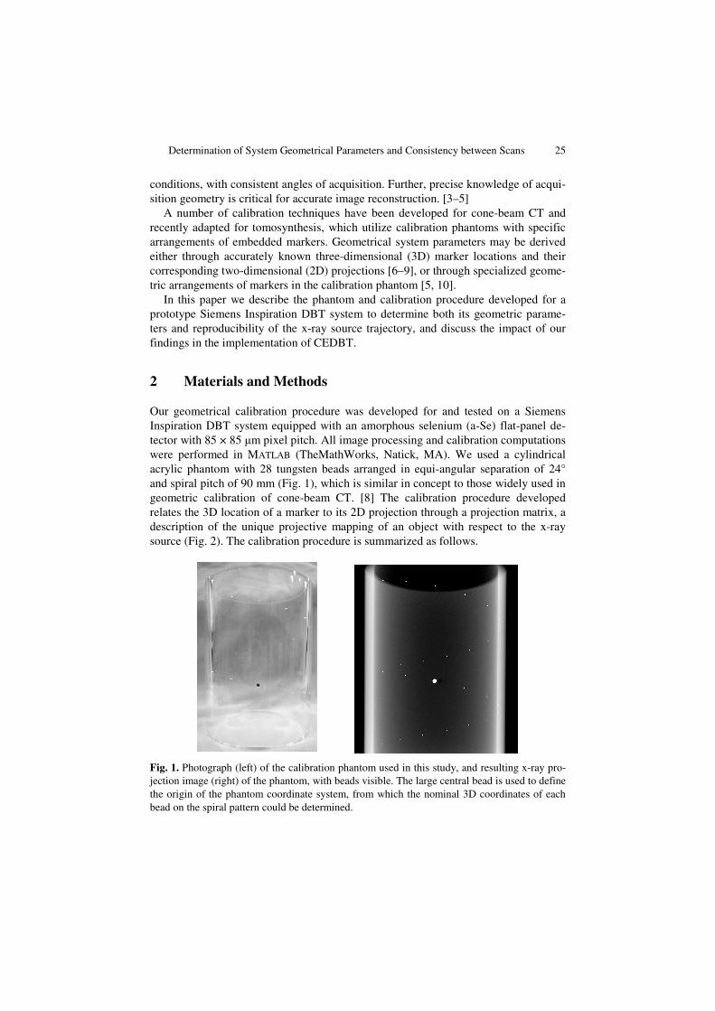
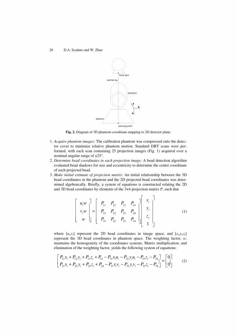
Our geometrical calibration procedure was developed for and tested on a Siemens Inspiration DBT system equipped with an amorphous selenium (a-Se) flat-panel de-tector with 85 × 85 μm pixel pitch. All image processing and calibration computations were performed in MATLAB (TheMathWorks, Natick, MA). We used a cylindrical acrylic phantom with 28 tungsten beads arranged in equi-angular separation of 24° and spiral pitch of 90 mm (Fig. 1), which is similar in concept to those widely used in geometric calibration of cone-beam CT. [8] The calibration procedure developed relates the 3D location of a marker to its 2D projection through a projection matrix, a description of the unique projective mapping of an object with respect to the x-ray source (Fig. 2). The calibration procedure is summarized as follows.
Fig. 1. Photograph (left) of the calibration phantom used in this study, and resulting x-ray pro-jection image (right) of the phantom, with beads visible. The large central bead is used to define the origin of the phantom coordinate system, from which the nominal 3D coordinates of each bead on the spiral pattern could be determined.
26 D.A. Scaduto and W. Zhao
Fig. 2. Diagram of 3D phantom coordinate mapping to 2D detector plane
1. Acquire phantom images: The calibration phantom was compressed onto the detec-tor cover to minimize relative phantom motion. Standard DBT scans were per-formed, with each scan containing 25 projection images (Fig. 1) acquired over a nominal angular range of ±25°.
2. Determine bead coordinates in each projection image: A bead detection algorithm evaluated bead shadows for size and eccentricity to determine the center coordinate of each projected bead.
3. Make initial estimate of projection matrix: An initial relationship between the 3D bead coordinates in the phantom and the 2D projected bead coordinates was deter-mined algebraically. Briefly, a system of equations is constructed relating the 2D and 3D bead coordinates by elements of the 3×4 projection matrix P, such that
uiw
viw
w
=
P11
P12
P13
P14
P21
P22
P23
P24
P31 P32 P33 P34
xi
yi
zi
1
(1)
where [ui,vi] represent the 2D bead coordinates in image space, and [xi,yi,zi] represent the 3D bead coordinates in phantom space. The weighting factor, w, maintains the homogeneity of the coordinates systems. Matrix multiplication, and elimination of the weighting factor, yields the following system of equations:
11 12 13 14 31 32 33 34
21 22 23 24 31 32 33 34
0
0i i i i i i i i
i i i i i i i i
P x P y P z P P x u P y u P z P
P x P y P z P P x v P y v P z P
+ + + − − − − = + + + − − − −
(2)
central ray
focal spot
phantom
detector
piercing point
Determination of System Geometrical Parameters and Consistency between Scans 27
These expressions are used to construct a matrix, which includes the 3D bead coordinates and their corresponding 2D image coordinates. Singular value decom-position is employed to find a solution to the system of equations, representing a linear solution of the projection matrix.
4. Minimize re-projection error: The projection matrix is more accurately estimated by iteratively minimizing the square distance between measured bead coordinates and re-projected bead coordinates using the estimated P. We used the Levenberg-Marquardt nonlinear least-squares fit algorithm to minimize the objec-tive function
( )2[ , ] , [ , , ]T T
i i i i ii
E d u v P x y z= . (3)
Optimization is terminated when a minimum residual re-projection error is achieved.
5. Decompose optimized projection matrix to derive source location: The projection matrix may be factored into three component matrices, such that
[ ]|P K R t= (4)
where the 3×3 rotation matrix R and the 3×1 translation vector t describe the orien-tation and location of the phantom with respect to the x-ray source, and the upper triangular intrinsic matrix K may be decomposed as
0
0
1
x
y
s u
K v
αα
=
(5)
where αx and αy represent pixel-scaling factors, s represents a skew-parameter for non-square pixels, and u0 and v0 are coordinates of the piercing point where the central x-ray enters the x-ray detector.
Thus, these three matrices reveal detector orientation, source to detector distance and x-ray source location. For stationary detectors, the most important of these parameters is the x-ray source location with respect to the stationary detector.
3 Results
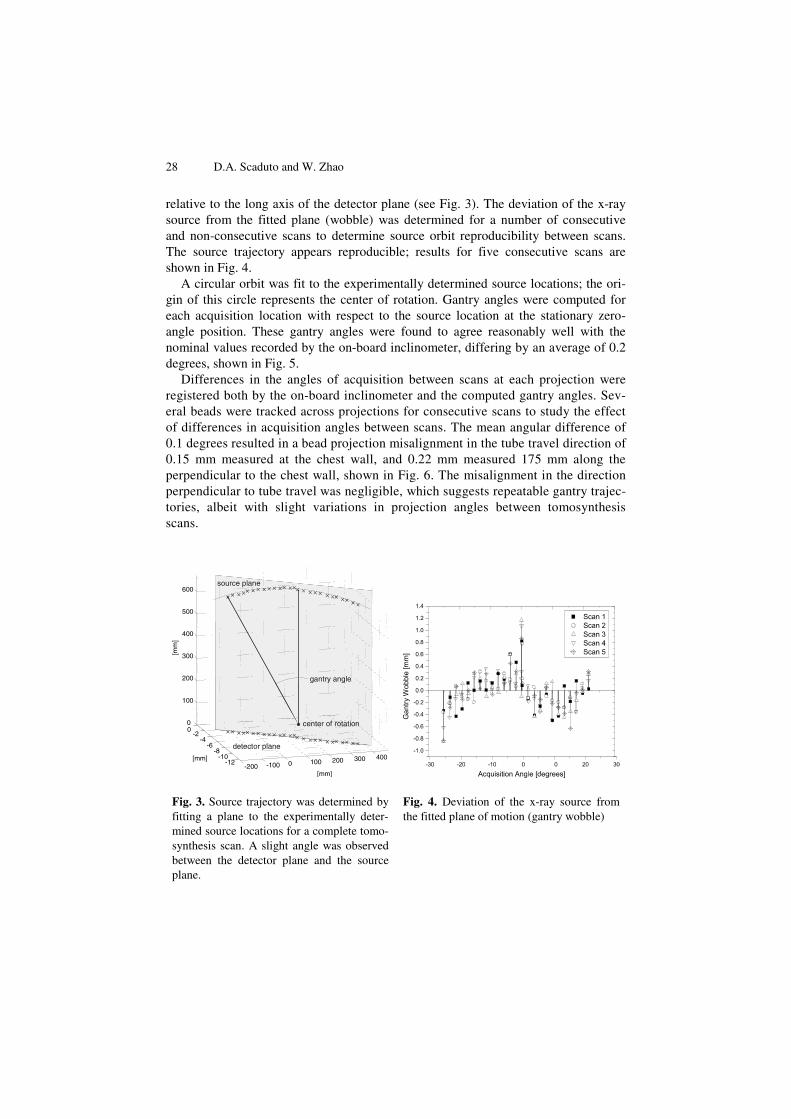
Using the method described above, projection matrices, P, were computed for each angle in a tomosynthesis scan, from which the x-ray source location (with respect to the detector plane) was derived. A plane of motion fitted to the source trajectory of each scan was found to be perpendicular to the detector, with a 0.85 degree rotation
28 D.A. Scaduto and W. Zhao
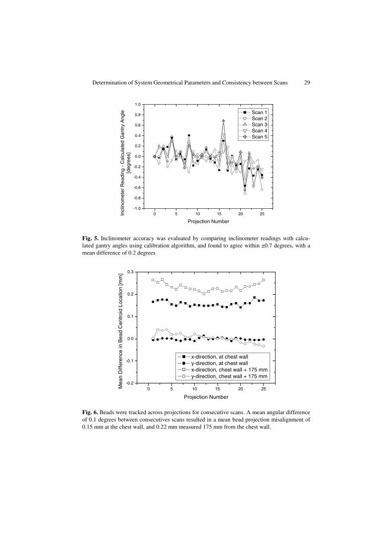
relative to the long axis of the detector plane (see Fig. 3). The deviation of the x-ray source from the fitted plane (wobble) was determined for a number of consecutive and non-consecutive scans to determine source orbit reproducibility between scans. The source trajectory appears reproducible; results for five consecutive scans are shown in Fig. 4.
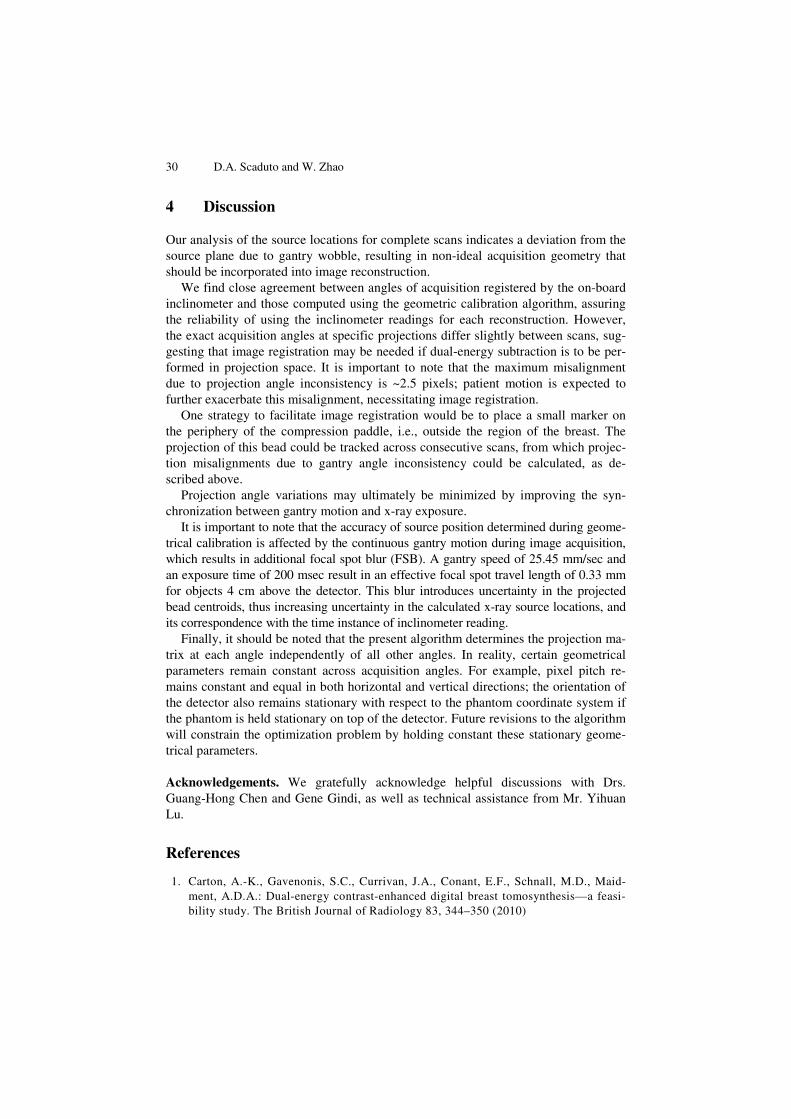
A circular orbit was fit to the experimentally determined source locations; the ori-gin of this circle represents the center of rotation. Gantry angles were computed for each acquisition location with respect to the source location at the stationary zero-angle position. These gantry angles were found to agree reasonably well with the nominal values recorded by the on-board inclinometer, differing by an average of 0.2 degrees, shown in Fig. 5.
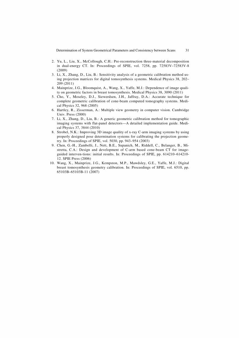
Differences in the angles of acquisition between scans at each projection were registered both by the on-board inclinometer and the computed gantry angles. Sev-eral beads were tracked across projections for consecutive scans to study the effect of differences in acquisition angles between scans. The mean angular difference of 0.1 degrees resulted in a bead projection misalignment in the tube travel direction of 0.15 mm measured at the chest wall, and 0.22 mm measured 175 mm along the perpendicular to the chest wall, shown in Fig. 6. The misalignment in the direction perpendicular to tube travel was negligible, which suggests repeatable gantry trajec-tories, albeit with slight variations in projection angles between tomosynthesis scans.
Fig. 3. Source trajectory was determined by fitting a plane to the experimentally deter-mined source locations for a complete tomo-synthesis scan. A slight angle was observed between the detector plane and the source plane.
Fig. 4. Deviation of the x-ray source from the fitted plane of motion (gantry wobble)
-200 -100 0 100 200 300 400-12
-10-8
-6-4
-200
100
200
300
400
500
600
[mm]
[mm
]
[mm]
detector plane
source plane
center of rotation
gantry angle
Determination of System Geometrical Parameters and Consistency between Scans 29
Fig. 5. Inclinometer accuracy was evaluated by comparing inclinometer readings with calcu-lated gantry angles using calibration algorithm, and found to agree within ±0.7 degrees, with a mean difference of 0.2 degrees
Fig. 6. Beads were tracked across projections for consecutive scans. A mean angular difference of 0.1 degrees between consecutives scans resulted in a mean bead projection misalignment of 0.15 mm at the chest wall, and 0.22 mm measured 175 mm from the chest wall.
0 5 10 15 20 25-1.0
-0.8
-0.6
-0.4
-0.2
0.0
0.2
0.4
0.6
0.8
1.0
Incl
inom
eter
Rea
ding
- C
alcu
late
d G
antr
y A
ngle
[deg
rees
]
Projection Number
Scan 1 Scan 2 Scan 3 Scan 4 Scan 5
0 5 10 15 20 25-0.2
-0.1
0.0
0.1
0.2
0.3
Mea
n D
iffer
ence
in B
ead
Cen
troi
d Lo
catio
n [m
m]
Projection Number
x-direction, at chest wall y-direction, at chest wall x-direction, chest wall + 175 mm y-direction, chest wall + 175 mm
30 D.A. Scaduto and W. Zhao
4 Discussion
Our analysis of the source locations for complete scans indicates a deviation from the source plane due to gantry wobble, resulting in non-ideal acquisition geometry that should be incorporated into image reconstruction.
We find close agreement between angles of acquisition registered by the on-board inclinometer and those computed using the geometric calibration algorithm, assuring the reliability of using the inclinometer readings for each reconstruction. However, the exact acquisition angles at specific projections differ slightly between scans, sug-gesting that image registration may be needed if dual-energy subtraction is to be per-formed in projection space. It is important to note that the maximum misalignment due to projection angle inconsistency is ~2.5 pixels; patient motion is expected to further exacerbate this misalignment, necessitating image registration.
One strategy to facilitate image registration would be to place a small marker on the periphery of the compression paddle, i.e., outside the region of the breast. The projection of this bead could be tracked across consecutive scans, from which projec-tion misalignments due to gantry angle inconsistency could be calculated, as de-scribed above.
Projection angle variations may ultimately be minimized by improving the syn-chronization between gantry motion and x-ray exposure.
It is important to note that the accuracy of source position determined during geome-trical calibration is affected by the continuous gantry motion during image acquisition, which results in additional focal spot blur (FSB). A gantry speed of 25.45 mm/sec and an exposure time of 200 msec result in an effective focal spot travel length of 0.33 mm for objects 4 cm above the detector. This blur introduces uncertainty in the projected bead centroids, thus increasing uncertainty in the calculated x-ray source locations, and its correspondence with the time instance of inclinometer reading.
Finally, it should be noted that the present algorithm determines the projection ma-trix at each angle independently of all other angles. In reality, certain geometrical parameters remain constant across acquisition angles. For example, pixel pitch re-mains constant and equal in both horizontal and vertical directions; the orientation of the detector also remains stationary with respect to the phantom coordinate system if the phantom is held stationary on top of the detector. Future revisions to the algorithm will constrain the optimization problem by holding constant these stationary geome-trical parameters.
Acknowledgements. We gratefully acknowledge helpful discussions with Drs. Guang-Hong Chen and Gene Gindi, as well as technical assistance from Mr. Yihuan Lu.
References
1. Carton, A.-K., Gavenonis, S.C., Currivan, J.A., Conant, E.F., Schnall, M.D., Maid-ment, A.D.A.: Dual-energy contrast-enhanced digital breast tomosynthesis—a feasi-bility study. The British Journal of Radiology 83, 344–350 (2010)
Determination of System Geometrical Parameters and Consistency between Scans 31
2. Yu, L., Liu, X., McCollough, C.H.: Pre-reconstruction three-material decomposition in dual-energy CT. In: Proceedings of SPIE, vol. 7258, pp. 72583V–72583V-8 (2009)
3. Li, X., Zhang, D., Liu, B.: Sensitivity analysis of a geometric calibration method us-ing projection matrices for digital tomosynthesis systems. Medical Physics 38, 202–209 (2011)
4. Mainprize, J.G., Bloomquist, A., Wang, X., Yaffe, M.J.: Dependence of image quali-ty on geometric factors in breast tomosynthesis. Medical Physics 38, 3090 (2011)
5. Cho, Y., Moseley, D.J., Siewerdsen, J.H., Jaffray, D.A.: Accurate technique for complete geometric calibration of cone-beam computed tomography systems. Medi-cal Physics 32, 968 (2005)
6. Hartley, R., Zisserman, A.: Multiple view geometry in computer vision. Cambridge Univ. Press (2000)
7. Li, X., Zhang, D., Liu, B.: A generic geometric calibration method for tomographic imaging systems with flat-panel detectors—A detailed implementation guide. Medi-cal Physics 37, 3844 (2010)
8. Strobel, N.K.: Improving 3D image quality of x-ray C-arm imaging systems by using properly designed pose determination systems for calibrating the projection geome-try. In: Proceedings of SPIE, vol. 5030, pp. 943–954 (2003)
9. Chen, G.-H., Zambelli, J., Nett, B.E., Supanich, M., Riddell, C., Belanger, B., Mi-stretta, C.A.: Design and development of C-arm based cone-beam CT for image-guided interven-tions: initial results. In: Proceedings of SPIE, pp. 614210–614210-12. SPIE Press (2006)
10. Wang, X., Mainprize, J.G., Kempston, M.P., Mawdsley, G.E., Yaffe, M.J.: Digital breast tomosynthesis geometry calibration. In: Proceedings of SPIE, vol. 6510, pp. 65103B–65103B-11 (2007)
Copyright © 2022 FDOKUMEN


![Breast percent density estimation from 3D reconstructed digital breast tomosynthesis images [6913-43]](https://static.fdokumen.com/doc/165x107/6336264964d291d2a302c4a3/breast-percent-density-estimation-from-3d-reconstructed-digital-breast-tomosynthesis.jpg)