
Determination of Residual Strain by Combining EBSD and DIC Techniques
10
328 Int. J. Materials and Product Technology, Vol. 37, Nos. 3/4, 2010 Copyright © 2010 Inderscience Enterprises Ltd. Determination of residual strain by combining EBSD and DIC techniques Jui-Chao Kuo* and Han-Hong Wang Department of Materials Science and Engineering, National Cheng-Kung University, No.1, University Road, Tainan 701, Taiwan, ROC E-mail: [email protected] E-mail: [email protected] *Corresponding author Abstract: Electron Back-Scatter Diffraction (EBSD) can be applied to determine lattice defect and local strain distortion. The strain components were obtained with the help of the shifting of zone axis in Kikuchi patterns generated from EBSD. The displacement of zone axis in Kikuchi pattern was determined by using Digital Image Correlation (DIC) method, which provides a great resolution down to 0.01 pixels, which means the ideal sensitivity to be ~3.6 × 10 –5 . However, the errors of calculating the residual strain can result from the image quality of Kikuchi patterns, such as the formation of dark areas in the Kikuchi patterns and the background noise. Keywords: residual strain; electron diffraction; EBSD; electron back-scatter diffraction; DIC; digital image correlation. Reference to this paper should be made as follows: Kuo, J-C. and Wang, H-H. (2010) ‘Determination of residual strain by combining EBSD and DIC techniques’, Int. J. Materials and Product Technology, Vol. 37, Nos. 3/4, pp.328–337. Biographical notes: J-C. Kuo received his PhD in Materials Science and Engineering from Technical University at Aachen (RWTH Aachen), Germany. He is currently an Assistant Professor at the Department of Materials Science and engineering, National Cheng-Kung University, Tainan, Taiwan, ROC. His current research focuses on microstructure mechanics, texture and residual stress. H-H. Wang is a Graduate student in the Department of Materials Science and Engineering, National Cheng-Kung University, Tainan, Taiwan, ROC. His study focuses on the determination of residual strain by combining Electron Back-Scatter Diffraction (EBSD) and Digital Image Correlation (DIC) techniques. 1 Introduction In the production and subsequent heat treatment of semiconductor structures and devices, residual stress fields interact with intrinsic defects such as dislocations in materials and influence device properties and their reliability. The understanding of the local state
Transcript of Determination of Residual Strain by Combining EBSD and DIC Techniques

328 Int. J. Materials and Product Technology, Vol. 37, Nos. 3/4, 2010
Copyright © 2010 Inderscience Enterprises Ltd.
Determination of residual strain by combining EBSD and DIC techniques
Jui-Chao Kuo* and Han-Hong Wang Department of Materials Science and Engineering, National Cheng-Kung University, No.1, University Road, Tainan 701, Taiwan, ROC E-mail: [email protected] E-mail: [email protected] *Corresponding author
Abstract: Electron Back-Scatter Diffraction (EBSD) can be applied to determine lattice defect and local strain distortion. The strain components were obtained with the help of the shifting of zone axis in Kikuchi patterns generated from EBSD. The displacement of zone axis in Kikuchi pattern was determined by using Digital Image Correlation (DIC) method, which provides a great resolution down to 0.01 pixels, which means the ideal sensitivity to be ~3.6 × 10⁻⁵. However, the errors of calculating the residual strain can result from the image quality of Kikuchi patterns, such as the formation of dark areas in the Kikuchi patterns and the background noise.
Keywords: residual strain; electron diffraction; EBSD; electron back-scatter diffraction; DIC; digital image correlation.
Reference to this paper should be made as follows: Kuo, J-C. and Wang, H-H. (2010) ‘Determination of residual strain by combining EBSD and DIC techniques’, Int. J. Materials and Product Technology, Vol. 37, Nos. 3/4, pp.328–337.
Biographical notes: J-C. Kuo received his PhD in Materials Science and Engineering from Technical University at Aachen (RWTH Aachen), Germany. He is currently an Assistant Professor at the Department of Materials Science and engineering, National Cheng-Kung University, Tainan, Taiwan, ROC. His current research focuses on microstructure mechanics, texture and residual stress.
H-H. Wang is a Graduate student in the Department of Materials Science and Engineering, National Cheng-Kung University, Tainan, Taiwan, ROC. His study focuses on the determination of residual strain by combining Electron Back-Scatter Diffraction (EBSD) and Digital Image Correlation (DIC) techniques.
1 Introduction
In the production and subsequent heat treatment of semiconductor structures and devices, residual stress fields interact with intrinsic defects such as dislocations in materials and influence device properties and their reliability. The understanding of the local state
Determination of residual strain by combining EBSD and DIC techniques 329
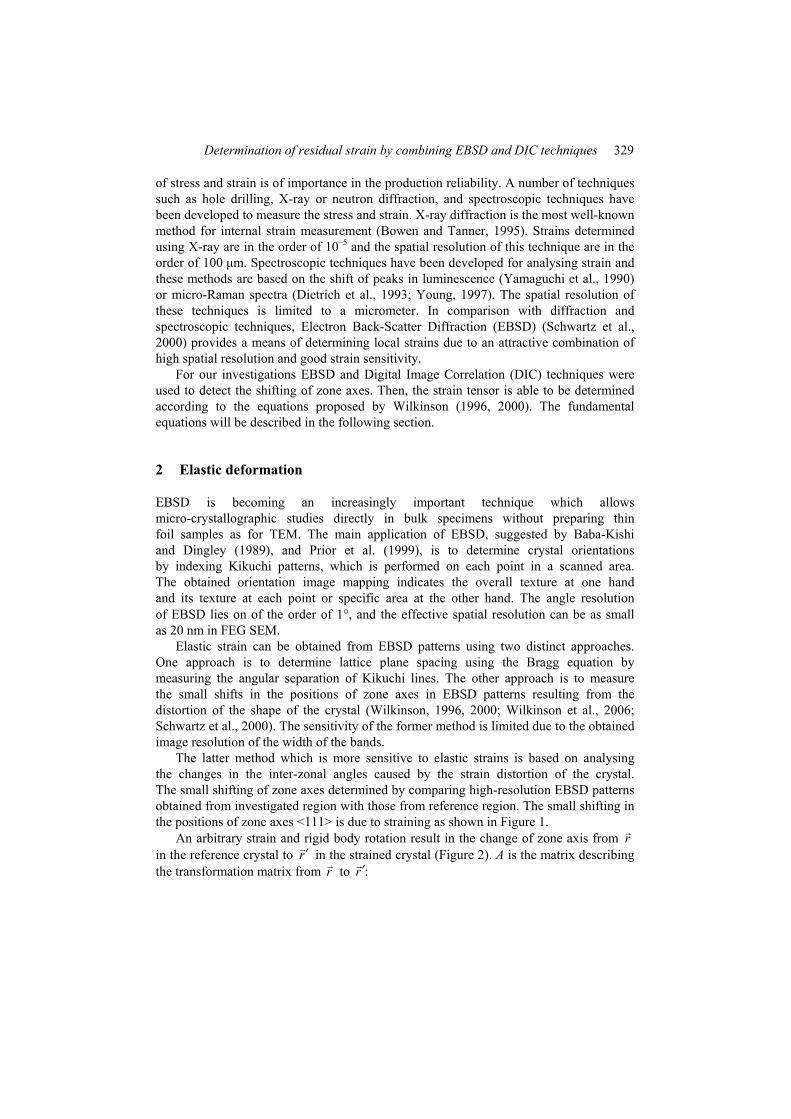
of stress and strain is of importance in the production reliability. A number of techniques such as hole drilling, X-ray or neutron diffraction, and spectroscopic techniques have been developed to measure the stress and strain. X-ray diffraction is the most well-known method for internal strain measurement (Bowen and Tanner, 1995). Strains determined using X-ray are in the order of 10–5 and the spatial resolution of this technique are in the order of 100 µm. Spectroscopic techniques have been developed for analysing strain and these methods are based on the shift of peaks in luminescence (Yamaguchi et al., 1990) or micro-Raman spectra (Dietrich et al., 1993; Young, 1997). The spatial resolution of these techniques is limited to a micrometer. In comparison with diffraction and spectroscopic techniques, Electron Back-Scatter Diffraction (EBSD) (Schwartz et al., 2000) provides a means of determining local strains due to an attractive combination of high spatial resolution and good strain sensitivity.
For our investigations EBSD and Digital Image Correlation (DIC) techniques were used to detect the shifting of zone axes. Then, the strain tensor is able to be determined according to the equations proposed by Wilkinson (1996, 2000). The fundamental equations will be described in the following section.
2 Elastic deformation
EBSD is becoming an increasingly important technique which allows micro-crystallographic studies directly in bulk specimens without preparing thin foil samples as for TEM. The main application of EBSD, suggested by Baba-Kishi and Dingley (1989), and Prior et al. (1999), is to determine crystal orientations by indexing Kikuchi patterns, which is performed on each point in a scanned area. The obtained orientation image mapping indicates the overall texture at one hand and its texture at each point or specific area at the other hand. The angle resolution of EBSD lies on of the order of 1°, and the effective spatial resolution can be as small as 20 nm in FEG SEM.
Elastic strain can be obtained from EBSD patterns using two distinct approaches. One approach is to determine lattice plane spacing using the Bragg equation by measuring the angular separation of Kikuchi lines. The other approach is to measure the small shifts in the positions of zone axes in EBSD patterns resulting from the distortion of the shape of the crystal (Wilkinson, 1996, 2000; Wilkinson et al., 2006; Schwartz et al., 2000). The sensitivity of the former method is limited due to the obtained image resolution of the width of the bands.
The latter method which is more sensitive to elastic strains is based on analysing the changes in the inter-zonal angles caused by the strain distortion of the crystal. The small shifting of zone axes determined by comparing high-resolution EBSD patterns obtained from investigated region with those from reference region. The small shifting in the positions of zone axes <111> is due to straining as shown in Figure 1.
An arbitrary strain and rigid body rotation result in the change of zone axis from r in the reference crystal to r′ in the strained crystal (Figure 2). A is the matrix describing the transformation matrix from r to :r′

330 J-C. Kuo and H-H. Wang
u u ux y zv v vA Ix y zw w wx y z
∂ ∂ ∂ ∂ ∂ ∂ ∂ ∂ ∂− = ∂ ∂ ∂ ∂ ∂ ∂ ∂ ∂ ∂
(1)
and
.r Ar′ = (2)
(u, v, w) and (x, y, z) are the vectors of the displacement and the position along the axis, respectively. The displacement caused by strain and rotation is indicated as ,Q which is related to A by:
( ) .Q r r A I r′= − = − (3)
The projection of Q is shown as ,q which is measured from EBSD and q is given:
{ ( 1) }q Q r A I rλ λ= − = − + (4)
where λ is an unknown scalar. After eliminating the unknown scalar λ, two equations are left with eight variables:
2 21 3 2 3 3 1 2 1 3 1 1 3
2 22 3 1 3 3 1 2 2 3 2 2 3.
u w u u w wr r r r r r r r r q r qx z y z y x
v w v v w wr r r r r r r r r q r qy z x z x y
∂ ∂ ∂ ∂ ∂ ∂ − + + − − = − ∂ ∂ ∂ ∂ ∂ ∂ ∂ ∂ ∂ ∂ ∂ ∂− + + − − = − ∂ ∂ ∂ ∂ ∂ ∂
(5)
Therefore, it needs to measure q at four zone axes to determine the eight values known as the displacement gradient:
, , , , , , , .u v u w w v u w v wy x z x y z x z y z
∂ ∂ ∂ ∂ ∂ ∂ ∂ ∂ ∂ ∂ − − ∂ ∂ ∂ ∂ ∂ ∂ ∂ ∂ ∂ ∂
The terms ∂u/∂x, ∂v/∂y, ∂w/∂z cannot be separated, because a simple change in lattice parameter generates no change in the angles between the zone axes and does not cause any zone axis shift in the EBSD pattern (Wilkinson, 1996). Therefore, in this study we focus on the other six components known as the displacement gradient. When the strain is very small, the shear strain can be derived from the displacement gradient (Wagoner and Chenot, 1996):
, , .xy yz zxu v u w w vy x z x y z
ε ε ε ∂ ∂ ∂ ∂ ∂ ∂ = + = + = + ∂ ∂ ∂ ∂ ∂ ∂ (6)

Determination of residual strain by combining EBSD and DIC techniques 331
Figure 1 The schematic illustration of the shifting of <111> directions in strained cubic unit cell and in unstrained cubic unit cell
Figure 2 Schematic diagram showing how a strain and rotation act to alter a zone axis direction r shifting across the EBSD screen by q
Source: Wilkinson (1996)
3 Digital Image Correlation
Displacements and displacement gradients can be determined from digital images based on DIC (Bruck et al., 1989; Sun et al., 1997). The image before deformation can be divided into discrete sub-images (facets) using the concept of finite-element method. The grey-scale summation of the associate sub-images before and after the deformation is the same. Assume that the sub-image before deformation is image A, and the sub-image after deformation is image B. The use of DIC is the image matching algorithm according to the method of the least-squares-matching, in which two digitised images are compared and the local relation function of these two images is determined. An image correlation function can be used to determine the degree of similarity between these two images. The definition of image correlation function is (Chu et al., 1985; Russell and Sutton, 1989) as follows:
2 2COF ij ij
ij ij
g g
g g=
⋅∑∑ ∑
(7)
where gij and ijg are the grey-scale of image A at coordinate (i, j) and image B at coordinate ( , ),i j respectively. The coordinate ( , )i j is the corresponding coordinate (i, j) of image A in image B. The image correlation function of every sub-image will be optimised to find the highest correlation value.

332 J-C. Kuo and H-H. Wang
The coordinates (x, y) and (x*, y*) are related by the displacement function between the two images, where P and P* are the positions before and after deformation, respectively, as shown in Figure 1. If the motion of the object relative to the camera is parallel to the image plane, then the two coordinates are related by Bruck et al. (1989):
*
*
( , )
( , ) .
u ux x u x y x yx yv vy y v x y x yx y
∂ ∂= + + ∆ + ∆∂ ∂∂ ∂= + + ∆ + ∆∂ ∂
(8)
The use of DIC is able to find the corresponding function between the sub-images. The displacements of each node before and after deformation can be determined. For small strains like Green-Lagrange’s tensor, E is approximated as follows:
1 [ ]2
TE F F I= ⊗ − (9)
where F is the tensor of the displacement gradient, and I is the unit matrix. The tensor E can also be expressed in terms of displacement field (Chu et al., 1985; Allais et al., 1994):
, , , ,1 1( )2 2ij i j j i k i k jE u u u u= + + (10)
where i, j, k ∈ (x, y) and ui,j = δui/δxj. Hence, the strain is given: 221
2yx x
xx
uu ux x x
ε ∂ ∂ ∂ = + + ∂ ∂ ∂
(11)
2212
y yxyy
u uuy y y
ε ∂ ∂ ∂ = + + ∂ ∂ ∂
(12)
1 1 .2 2
y y yx x xxy
u u uu u uy x x y x y
ε∂ ∂ ∂ ∂ ∂ ∂
= + + + ∂ ∂ ∂ ∂ ∂ ∂ (13)
The Von Mises strain is a strain invariant defined by:
2 2 21 2 2 3 3 1( ) ( ) ( )
2VMε ε ε ε ε εε
− + − + −=
(14)
where ε1, ε2 and ε3 are the principle Green strains.
4 Experiment
The specimen used in this work consisted of AlN grown epitaxially on Si (111) substrates and layer thickness was about 1 µm. Epitaxial layer on planar substrate was used for introducing elastic strain on substrate. The specimen was supplied by the Centre

Determination of residual strain by combining EBSD and DIC techniques 333
for Micro/Nano Science and Technology in National Cheng-Kung University. The cross section was polished from 5 µm alumina to 0.04 µm colloidal silica.
The EBSD detection unit is mounted on a FEI Quanta 400 F SEM with a field emission gun. Samples were analysed at 20 kV at spot size five and the work distance was set at 17 mm. This spot size typically corresponds to an incident beam current of approximately 2 nA. Kikuchi patterns were acquired using an EDAX Instruments OIMTM Data Collection 5.0 system comprising of a peltiercooled CCD camera. The tilting angle of the specimen was of 70°, which allows more electrons to be diffracted. In this work, the CCD camera was 26.3 mm from the sample. A series of EBSD patterns was then obtained along a line scan of L4 across the interface of AlN/Si as shown in Figure 3 with a step size of 0.05 µm and stored on computer for subsequent analysis. After obtaining the patterns captured at different positions, the pattern recorded at a distance of 2.75 µm from the interface is assumed without straining as a reference pattern, because this pattern is far away from the interface between AlN/Si having a lattice mismatch. The Kikuchi patterns recorded at different positions were compared with the reference pattern to detect the displacement of zone axes.
Figure 3 Scanning lines of L1 to L5 and scanning directions on epitaxial layer
It needed four zone axes to determine eight unknowns from equation (5) and the zone axes were selected as [0 0 –1], [–1 1 –1], [–1 –1 –4], and [–1 0 –1] (Figure 4). The marked areas of the selected zone axes were approximately determined by the operator and a 340 × 340 pixel area of this selected region was extracted from the raw pattern. The raw images were then passed through a filter, in which the difference in a pixel’s intensity was averaged over the 340 × 340 pixel area. It served to remove any residual background intensity, which can lead to unwanted error during the use of DIC software. With the help of the self-developed DIC software based on DIC (Bruck et al., 1989; Chu et al., 1985), the shift of each zone axis at each Kikuchi pattern can be determined. The use of DIC is the image matching algorithm according to the method of the least-squares-matching, in which two digitised patterns are compared and the local relation function of these two images is determined and the displacements of four zone axes can be determined. The DIC method provides a resolution down to 1 × 10⁻⁶ (Tung et al., 2006). Therefore, the obtained displacements of the four zone axes were served to calculate the shear strain components according to equation (5).

334 J-C. Kuo and H-H. Wang
Figure 4 Four zone axes are selected for the strain calculation
5 Results and discussion
Figure 5 shows the displacement gradients in dependence of the distance from the reference point in L4 for example. Except the abrupt peak at the distance of 1.1 µm, it is observed that there is little variation in the displacement in the order of 0.05 from 0 µm to 2.0 µm, where the interface is at distance of 2.75 µm. When being close to the interface, the variation increases in Figure 5 and this suggests that the closer to the epitaxial layer, the larger strain suffered for silicon substrate due to the mismatch in the lattice parameters of Si and AlN.
Figure 5 Profile of displacement gradient along with distance from the reference point at the silicon substrate
The shear strain obtained from the displacement gradient is shown in Figure 6. Except the abrupt peak at the distance of 1.1 µm, there is little variation in the shear strains of xy and zx at distance smaller than 2.0 µm, while at the same condition the component of yz shows a larger variation than those of xy and zx. Above the distance of 2.0 µm the variation of the shear strain increases.
However, noises resulting from diffraction could lead to calculation errors by using DIC software. This is because the DIC software is based on DIC. These noises caused by electrons randomly bombarding the phosphor screen are shown in Figure 6. Although electrons generated from electron gun are diffracted with crystal planes and contributed to the contrast of Kikuchi bands, some electrons strike phosphor screen irregularly and

Determination of residual strain by combining EBSD and DIC techniques 335
this leads to form the noises on the patterns. These noises randomly distributed all over and different from pattern to pattern have a great influence on calculating the displacement of zone axes by using DIC software. To remove so-called noises, the raw images were then passed through a filter and this process is called ‘smooth’ process as shown in Figure 7. The noises are able to be successfully suppressed by using this smoothing process at one hand but the edge of the Kikuchi bands were also been blurred at the other hand.
In addition to background noises, the overlapped Kikuchi patterns generated from two phases close to the interface can also increase the analysis difficulties by using the DIC software. This effect is observed from the increased variation in the displacement gradient and the shear strain over 2.0 µm in Figures 5 and 6, where the interface lies at 2.75 µm.
Figure 6 Profile of shear strain along with distance from the reference point at the silicon substrate
Figure 7 Kikuchi patterns of Si (111) substrate (a) without smoothing process and (b) with smoothing process
(a) (b)
6 Conclusion and future work
We have proposed an easy but high precision way for elastic strain measurement by combining EBSD and DIC techniques. The strain sensitivity of this method lies in the order of 3.6 × 10⁻⁵. Owing to the nature of DIC technique, however, the sensitivity is

336 J-C. Kuo and H-H. Wang
limited by the quality of recorded Kikuchi patterns. Our future work focuses on developing reliable image processes to overcome the effects of background noises and of overlapped Kikuchi patterns to achieve the theoretical strain sensitivity.
Acknowledgement
We are grateful for the Centre for Micro/Nano Science and Technology in National Cheng-Kung University to support the specimen. This work was supported by the program of the National Science Council (NSC 96-2221-E-006-124).
References Allais, L., Bornert, M., Bretheau, T. and Caldemaison, D. (1994) ‘Experimental characterisation of
the local strain field in a heterogeneous elastoplastic material’, Acta. Metal. Mater., Vol. 42, pp.3865–3880.
Baba-Kishi, K.Z. and Dingley, D.J. (1989) ‘Application of backscatter kikuchi diffraction in the scanning electron microscope to the study of NiS2’, Journal of Applied Crystallography, Vol. 22, pp.189–200.
Bowen, D.K. and Tanner, B.K. (1995) ‘A method for the accurate comparison of lattice parameters’, Journal of Applied Crystallography, Vol. 28, pp.753–760.
Bruck, H.A., McNeill, S.R., Sutton, M.A. and Peters, W.H. (1989) ‘Digital image correlation using newton-raphson method of partial differential correlations’, Experimental Mechanics, Vol. 29, pp.261–267.
Chu, T.C., Ranson, W.F., Sutton, M.A. and Peters, W.H. (1985) ‘Application of digital-image-correlation techniques to experimental mechanics’, Experimental Mechanics, Vol. 25, pp.232–244.
Dietrich, B., Bugiel, E., Osten, H.J. and Zaumseil, P. (1993) ‘Raman investigations of elastic strain relief in si1–xGex layers on patterned silicon substrate’, Applied Physics Letters, Vol. 74, pp.7223–7227.
Prior, D.J., Boyle, A., Brenker, F., Cheadle, M.C. and Day, A. (1999) ‘The application of electron backscatter diffraction and orientation contrast imaging in the SEM to textural problems in rocks’, American Mineralogist, Vol. 84, pp.1741–1759.
Russell, S.S. and Sutton, M.A. (1989) ‘Strain field analysis aquired through correlation of x-ray radiography of a fiber reinforced composite laminate’, Experimental Mechanics, Vol. 29, pp.237–240.
Schwartz, A.J., Kumar, M. and Adams, B.L. (2000) Electron Backscatter Diffraction in Material Science, Springer.
Sun, Z., Lyons, J.S. and McNeil, S.R. (1997) ‘Measuring microscopic deformations with digital image correlation’, Optics and Lasers in Engineering, Vol. 27, No. 4, pp.409–428.
Tung, S.H., Kuo, J.C. and Shih, M.H. (2006) ‘Calibration of the image distortion induced error for a plane strain field measured using digital image correlation techniques’, Proceedings of the Eighth International Conference on Computational Structures Technology, 12–15 September, Las Palmas de Gran Canaria, Spain, Paper No. 139, p.313.
Wagoner, R.H. and Chenot, J.L. (1996) Fundamentals of Metal Forming, John Wiley and Sons, pp.118–149.
Wilkinson, A.J. (1996) ‘Measurement of elastic strains and small lattice rotations using electron back scatter diffraction’, Ultramicroscopy, Vol. 64, pp.237–247.
Wilkinson, A.J. (2000) ‘Advances in SEM-based diffraction studies of defects and strains in semiconductors’, Journal of Electron Microscopy, Vol. 49, pp.299–310.

Determination of residual strain by combining EBSD and DIC techniques 337
Wilkinson, A.J., Meaden, G. and Dingley, D.J. (2006) ‘High-resolution elastic strain measurement from electron backscatter diffraction patterns: new levels of sensitivity’, Ultramicroscopy, Vol. 106, pp.307–313.
Yamaguchi, M., Tachikawa, M., Sugo, M., Kondo, S. and Itoh, Y. (1990) ‘Analysis for dislocation density reduction in selective area grown gaas films on Si substrates’, Applied Physics Letters, Vol. 56, pp.27–29.
Young, R.J. (1997) ‘Analysis of composites using Raman and fluorescence microscopy – a review’, Journal of Microscopy, Vol. 185, pp.199–205.