Detailed energy saving performance analyses on thermal mass walls demonstrated in a zero energy...
8
Detailed energy saving performance analyses on thermal mass walls demonstrated in a zero energy house L. Zhu a, *, R. Hurt b , D. Correia b , R. Boehm b a School of Architecture, Tianjin University, Tianjin 300072, PR China b Center for Energy Research, University of Nevada, Las Vegas, NV 89154, USA 1. Introduction Utilization of thermal mass in buildings can be one of the most effective ways of reducing building heating and cooling loads, and this approach is applicable in locations that have large daily temperature variations. Thermal mass incorporated in the building reduces temperature swings and absorbs energy surpluses both from solar gains and internal heat gains. In addition, massive building envelope components delay and flatten thermal waves caused by exterior temperature swings. Numerous historic and current field studies have demonstrated that in some locations, heating and cooling energy demands in buildings containing massive walls could be lower than those in similar buildings constructed using lightweight wall technologies. The relevant work before 1996 was reviewed by Balaras [1]. Recently, Asan [2] used a one-dimensional transient heat conduc- tion equation and periodic boundary conditions to investigate the time lags and decrement factors for different building materials, and it was found that the thickness of the material is very deterministic from the time lag and decrement factor point of view. Strub et al. [3] used the second thermodynamic law to analyze the periodic heat transfer through a homogeneous mass wall. In addition, colors of exterior surfaces affecting solar radiation absorption have been investigated. It is concluded that the higher the level of solar radiation on one hand, and the lighter the building on the other, the more sensitive is the building’s performance to the envelope color [4,5]. Gregory et al. [6] studied the effect of mass on the thermal performance of various Australian residential construction systems. It was found that the thermal mass had a dramatic impact on the thermal behaviour of the modules studied, particularly in those where the thermal mass was within a protective envelope of insulation. Hacker et al. [7] extended the research to carbon dioxide emissions and environmental issues. Kalogirou et al. [8] presented the effects on heating and cooling loads resulting from the use of building thermal mass in Cyprus by modeling and simulation with the TRNSYS program. The diurnal temperature variations in Cyprus are ideal for the application of thermal mass, and the simulation results show that there is a reduction in the heating load requirement of the zone by about 47%, whereas at the same time a slight increase of the zone-cooling load is exhibited. Coupling thermal mass and night ventilation has been carried out [9–11]. Ogoli [12] monitored four environmental test chambers with different thermal mass levels under different ceiling types in Nairobi, Kenya. The low mass test chambers closely followed Energy and Buildings 41 (2009) 303–310 ARTICLE INFO Article history: Received 12 December 2007 Received in revised form 14 September 2008 Accepted 5 October 2008 Keywords: Thermal mass Dynamic performance Heat transfer Simulation Modeling ABSTRACT An insulated concrete wall system 1 was used on exterior walls of a zero energy house. Its thermal functions were investigated using actual data in comparison to a conventional wood frame system. The internal wall temperature of massive systems changes more slowly than the conventional wall constructions, leading to a more stable indoor temperature. The Energy10 simulated equivalent R-value and DBMS of the mass walls under actual climate conditions are, respectively, 6.98 (m 2 8C)/W and 3.39. However, the simulated heating energy use was much lower for the massive walls while the cooling load was a little higher. Further investigation on the heat flux indicates that the heat actually is transferred inside all day and night, which results in a higher cooling energy consumption. A one-dimensional model further verified these analyses, and the calculated results are in good agreement with the actual data. We conclude that the thermal mass wall does have the ability to store heat during the daytime and release it back at night, but in desert climates with high 24-h ambient temperature and intense sunlight, more heat will be stored than can be transferred back outside at night. As a result, an increased cooling energy will be required. ß 2008 Elsevier B.V. All rights reserved. * Corresponding author. E-mail address: [email protected] (L. Zhu). 1 T-Mass TM by the Dow Chemical Company. Contents lists available at ScienceDirect Energy and Buildings journal homepage: www.elsevier.com/locate/enbuild 0378-7788/$ – see front matter ß 2008 Elsevier B.V. All rights reserved. doi:10.1016/j.enbuild.2008.10.003
-
Upload
independent -
Category
Documents
-
view
4 -
download
0
Transcript of Detailed energy saving performance analyses on thermal mass walls demonstrated in a zero energy...
Detailed energy saving performance analyses on thermal mass wallsdemonstrated in a zero energy house
L. Zhu a,*, R. Hurt b, D. Correia b, R. Boehmb
a School of Architecture, Tianjin University, Tianjin 300072, PR ChinabCenter for Energy Research, University of Nevada, Las Vegas, NV 89154, USA
1. Introduction
Utilization of thermal mass in buildings can be one of the mosteffective ways of reducing building heating and cooling loads, andthis approach is applicable in locations that have large dailytemperature variations. Thermalmass incorporated in the buildingreduces temperature swings and absorbs energy surpluses bothfrom solar gains and internal heat gains. In addition, massivebuilding envelope components delay and flatten thermal wavescaused by exterior temperature swings. Numerous historic andcurrent field studies have demonstrated that in some locations,heating and cooling energy demands in buildings containingmassive walls could be lower than those in similar buildingsconstructed using lightweight wall technologies.
The relevant work before 1996 was reviewed by Balaras [1].Recently, Asan [2] used a one-dimensional transient heat conduc-tion equation and periodic boundary conditions to investigate thetime lags and decrement factors for different building materials,and it was found that the thickness of the material is verydeterministic from the time lag and decrement factor point of
view. Strub et al. [3] used the second thermodynamic law toanalyze the periodic heat transfer through a homogeneous masswall. In addition, colors of exterior surfaces affecting solarradiation absorption have been investigated. It is concluded thatthe higher the level of solar radiation on one hand, and the lighterthe building on the other, the more sensitive is the building’sperformance to the envelope color [4,5]. Gregory et al. [6] studiedthe effect of mass on the thermal performance of variousAustralian residential construction systems. It was found thatthe thermal mass had a dramatic impact on the thermal behaviourof the modules studied, particularly in those where the thermalmass was within a protective envelope of insulation. Hacker et al.[7] extended the research to carbon dioxide emissions andenvironmental issues. Kalogirou et al. [8] presented the effectson heating and cooling loads resulting from the use of buildingthermal mass in Cyprus by modeling and simulation with theTRNSYS program. The diurnal temperature variations in Cyprus areideal for the application of thermal mass, and the simulationresults show that there is a reduction in the heating loadrequirement of the zone by about 47%, whereas at the same timea slight increase of the zone-cooling load is exhibited. Couplingthermal mass and night ventilation has been carried out [9–11].Ogoli [12] monitored four environmental test chambers withdifferent thermal mass levels under different ceiling types inNairobi, Kenya. The low mass test chambers closely followed
Energy and Buildings 41 (2009) 303–310
A R T I C L E I N F O
Article history:Received 12 December 2007Received in revised form 14 September 2008Accepted 5 October 2008
Keywords:Thermal massDynamic performanceHeat transferSimulationModeling
A B S T R A C T
An insulated concrete wall system1 was used on exterior walls of a zero energy house. Its thermalfunctions were investigated using actual data in comparison to a conventional wood frame system. Theinternal wall temperature of massive systems changes more slowly than the conventional wallconstructions, leading to a more stable indoor temperature. The Energy10 simulated equivalent R-valueand DBMS of the mass walls under actual climate conditions are, respectively, 6.98 (m2 8C)/W and 3.39.However, the simulated heating energy use was much lower for the massive walls while the cooling loadwas a little higher. Further investigation on the heat flux indicates that the heat actually is transferredinside all day and night, which results in a higher cooling energy consumption. A one-dimensional modelfurther verified these analyses, and the calculated results are in good agreement with the actual data. Weconclude that the thermal mass wall does have the ability to store heat during the daytime and release itback at night, but in desert climates with high 24-h ambient temperature and intense sunlight, more heatwill be stored than can be transferred back outside at night. As a result, an increased cooling energy willbe required.
! 2008 Elsevier B.V. All rights reserved.
* Corresponding author.E-mail address: [email protected] (L. Zhu).
1 T-MassTM by the Dow Chemical Company.
Contents lists available at ScienceDirect
Energy and Buildings
journal homepage: www.e lsev ier .com/ locate /enbui ld
0378-7788/$ – see front matter ! 2008 Elsevier B.V. All rights reserved.doi:10.1016/j.enbuild.2008.10.003
alwebb
alwebb
alwebb
alwebb
alwebb
alwebb
outdoor conditions and did not offer any significant thermalstorage, while high thermal mass was very effective in loweringindoor maximum temperatures below the high outdoor maxima.An operational procedure that can determine optimal governingstrategies for building thermal processes was developed and wasapplied to a floor heating system in a passive solar room withthermal mass [13].
Instead of steady-state thermal performance, researchers atthe Oak Ridge National Laboratory (ORNL) have recently devel-oped a new measure for the dynamic thermal performance ofmassive walls, which was called Dynamic Benefit for MassiveSystems (DBMS). Kosny and Christian [14] used the Heating 7.2finite difference computer code developed for complex wallconstructions to model metal stud walls and their components.Kossecka and Kosny [15] analyzed the effect of mass andinsulation location on heating and cooling loads for sixcharacteristic wall configurations. In addition to the periodictemperature changes concerns, DOE-2.1E is employed for theenergy analysis for thewhole building in six different US climates.Instead of using a simplified one-dimensional parallel pathprogram, in [16] they suggested coupling three-dimensional heattransfer modeling and dynamic hot-box tests for complex wallsystems with the whole building thermal simulations. Further,they described a method of derivation of the conduction z-transfer function coefficients from response factors, for three-dimensional wall assemblies [17].
In suburban Las Vegas where the climate conditions aresupposedly favorable for massive system utilization, two identicalhomes have been built side by side: one using conventionalmethods and onewith innovative new technologies. The prototypewas designed to be a zero energy house (ZEH) with energy savingfeatures plus solar applications. Compared to the traditional woodframewalls, an insulated concretewall system (see footnote 1)wasused on all exterior walls of the ZEH. Real-time data logging hastaken place for over 2 years and has reflected the excellent energysaving performance of the ZEH. It is indeed a zero energy house asdesigned on the basis of annual electricity usage.
Using these two houses, a detailed investigation of the swingand dissipation functions during different seasons of the two kindsof wall construction is described. This will use the collected datafor wall temperatures and heat fluxes. In order to isolate thecontribution from themass walls, simulations with Energy10wereperformed to determine the energy saving percentage using TMY2data as well as actual local climate data after the model wascalibrated by total house load simulation. The dynamic perfor-mance characterizing factors of equivalent R-value andDBMSwereto be estimated. In addition, a one-dimensional model was applied
to estimate the details of the temperature distribution and thewalls’ time lag characteristics.
2. Wall construction
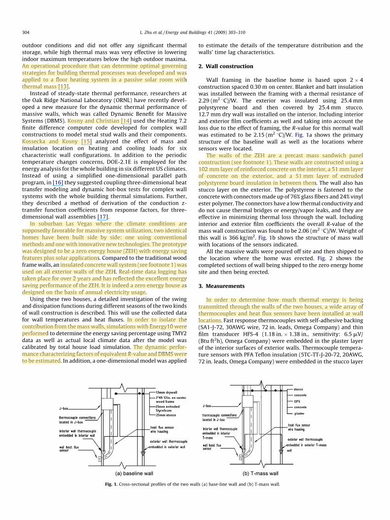
Wall framing in the baseline home is based upon 2 ! 4construction spaced 0.30 m on center. Blanket and batt insulationwas installed between the framing with a thermal resistance of2.29 (m2 8C)/W. The exterior was insulated using 25.4 mmpolystyrene board and then covered by 25.4 mm stucco.12.7 mm dry wall was installed on the interior. Including interiorand exterior film coefficients as well and taking into account theloss due to the effect of framing, the R-value for this normal wallwas estimated to be 2.15 (m2 8C)/W. Fig. 1a shows the primarystructure of the baseline wall as well as the locations wheresensors were located.
The walls of the ZEH are a precast mass sandwich panelconstruction (see footnote 1). These walls are constructed using a102 mm layer of reinforced concrete on the interior, a 51 mm layerof concrete on the exterior, and a 51 mm layer of extrudedpolystyrene board insulation in between them. The wall also hasstucco layer on the exterior. The polystyrene is fastened to theconcretewith connectorsmade up of 76% glass fibers and 24% vinylester polymer. The connectors have a low thermal conductivity anddo not cause thermal bridges or energy/vapor leaks, and they areeffective in minimizing thermal loss through the wall. Includinginterior and exterior film coefficients the overall R-value of themass wall construction was found to be 2.06 (m2 8C)/W. Weight ofthis wall is 366 kg/m2. Fig. 1b shows the structure of mass wallwith locations of the sensors indicated.
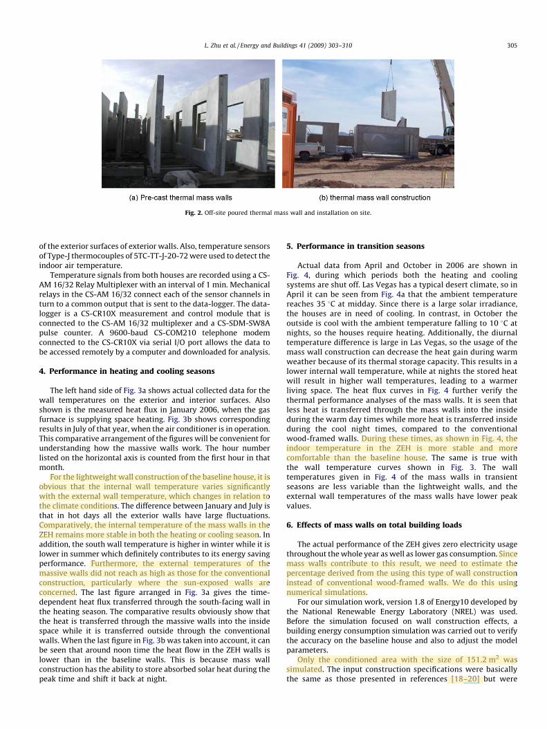
All the massive walls were poured off site and then shipped tothe location where the home was erected. Fig. 2 shows thecompleted sections of wall being shipped to the zero energy homesite and then being erected.
3. Measurements
In order to determine how much thermal energy is beingtransmitted through the walls of the two houses, a wide array ofthermocouples and heat flux sensors have been installed at walllocations. Fast response thermocouples with self-adhesive backing(SA1-J-72, 30AWG wire, 72 in. leads, Omega Company) and thinfilm transducer HFS-4 (1.18 in. ! 1.38 in., sensitivity: 6.5mV/(Btu ft2h), Omega Company) were embedded in the plaster layerof the interior surfaces of exterior walls. Thermocouple tempera-ture sensors with PFA Teflon insulation (5TC-TT-J-20-72, 20AWG,72 in. leads, Omega Company) were embedded in the stucco layer
Fig. 1. Cross-sectional profiles of the two walls (a) base-line wall and (b) T-mass wall.
L. Zhu et al. / Energy and Buildings 41 (2009) 303–310304
alwebb
alwebb
alwebb
alwebb
alwebb
alwebb
alwebb
alwebb
alwebb
alwebb
of the exterior surfaces of exterior walls. Also, temperature sensorsof Type-J thermocouples of 5TC-TT-J-20-72were used to detect theindoor air temperature.
Temperature signals from both houses are recorded using a CS-AM 16/32 Relay Multiplexer with an interval of 1 min. Mechanicalrelays in the CS-AM 16/32 connect each of the sensor channels inturn to a common output that is sent to the data-logger. The data-logger is a CS-CR10X measurement and control module that isconnected to the CS-AM 16/32 multiplexer and a CS-SDM-SW8Apulse counter. A 9600-baud CS-COM210 telephone modemconnected to the CS-CR10X via serial I/O port allows the data tobe accessed remotely by a computer and downloaded for analysis.
4. Performance in heating and cooling seasons
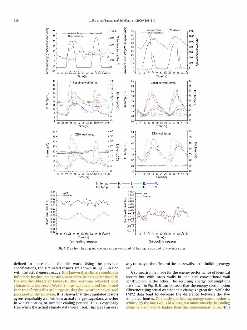
The left hand side of Fig. 3a shows actual collected data for thewall temperatures on the exterior and interior surfaces. Alsoshown is the measured heat flux in January 2006, when the gasfurnace is supplying space heating. Fig. 3b shows correspondingresults in July of that year, when the air conditioner is in operation.This comparative arrangement of the figures will be convenient forunderstanding how the massive walls work. The hour numberlisted on the horizontal axis is counted from the first hour in thatmonth.
For the lightweight wall construction of the baseline house, it isobvious that the internal wall temperature varies significantlywith the external wall temperature, which changes in relation tothe climate conditions. The difference between January and July isthat in hot days all the exterior walls have large fluctuations.Comparatively, the internal temperature of the mass walls in theZEH remains more stable in both the heating or cooling season. Inaddition, the south wall temperature is higher in winter while it islower in summer which definitely contributes to its energy savingperformance. Furthermore, the external temperatures of themassive walls did not reach as high as those for the conventionalconstruction, particularly where the sun-exposed walls areconcerned. The last figure arranged in Fig. 3a gives the time-dependent heat flux transferred through the south-facing wall inthe heating season. The comparative results obviously show thatthe heat is transferred through the massive walls into the insidespace while it is transferred outside through the conventionalwalls. When the last figure in Fig. 3b was taken into account, it canbe seen that around noon time the heat flow in the ZEH walls islower than in the baseline walls. This is because mass wallconstruction has the ability to store absorbed solar heat during thepeak time and shift it back at night.
5. Performance in transition seasons
Actual data from April and October in 2006 are shown inFig. 4, during which periods both the heating and coolingsystems are shut off. Las Vegas has a typical desert climate, so inApril it can be seen from Fig. 4a that the ambient temperaturereaches 35 8C at midday. Since there is a large solar irradiance,the houses are in need of cooling. In contrast, in October theoutside is cool with the ambient temperature falling to 10 8C atnights, so the houses require heating. Additionally, the diurnaltemperature difference is large in Las Vegas, so the usage of themass wall construction can decrease the heat gain during warmweather because of its thermal storage capacity. This results in alower internal wall temperature, while at nights the stored heatwill result in higher wall temperatures, leading to a warmerliving space. The heat flux curves in Fig. 4 further verify thethermal performance analyses of the mass walls. It is seen thatless heat is transferred through the mass walls into the insideduring the warm day times while more heat is transferred insideduring the cool night times, compared to the conventionalwood-framed walls. During these times, as shown in Fig. 4, theindoor temperature in the ZEH is more stable and morecomfortable than the baseline house. The same is true withthe wall temperature curves shown in Fig. 3. The walltemperatures given in Fig. 4 of the mass walls in transientseasons are less variable than the lightweight walls, and theexternal wall temperatures of the mass walls have lower peakvalues.
6. Effects of mass walls on total building loads
The actual performance of the ZEH gives zero electricity usagethroughout thewhole year aswell as lower gas consumption. Sincemass walls contribute to this result, we need to estimate thepercentage derived from the using this type of wall constructioninstead of conventional wood-framed walls. We do this usingnumerical simulations.
For our simulation work, version 1.8 of Energy10 developed bythe National Renewable Energy Laboratory (NREL) was used.Before the simulation focused on wall construction effects, abuilding energy consumption simulation was carried out to verifythe accuracy on the baseline house and also to adjust the modelparameters.
Only the conditioned area with the size of 151.2 m2 wassimulated. The input construction specifications were basicallythe same as those presented in references [18–20] but were
Fig. 2. Off-site poured thermal mass wall and installation on site.
L. Zhu et al. / Energy and Buildings 41 (2009) 303–310 305
alwebb
alwebb
alwebb
alwebb
alwebb
alwebb
alwebb
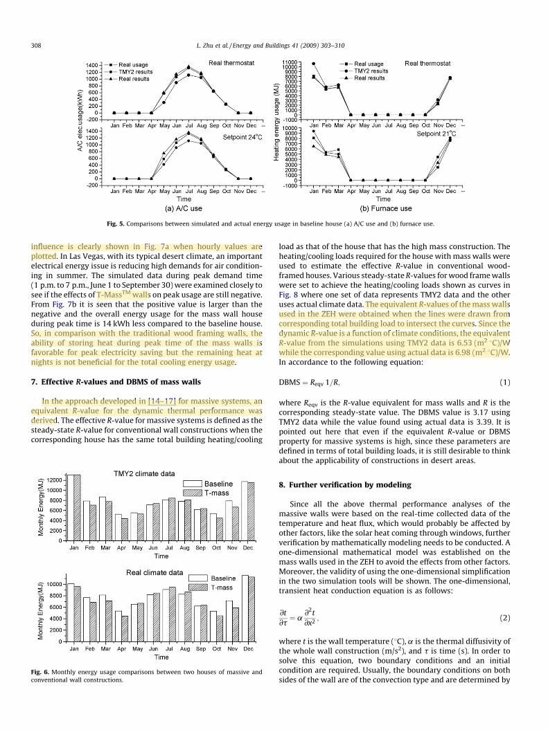
defined in more detail for this work. Using the previousspecifications, the simulated results are shown in Fig. 5 in linewith the actual energy usage. It is known that climate conditionsinfluence the simulated results, so besides the TMY2 data found inthe weather library of Energy10, the real-time collected localclimate datawere used.We did this using the required format andthen transferring this to Energy10 using the ‘‘weathermaker’’ toolpackaged in the software. It is shown that the simulated resultsagree remarkablywellwith the actual energy usage data,whetherin winter heating or summer cooling periods. This is especiallytrue when the actual climate data were used. This gives an easy
way to analyze the effects of themasswalls on the building energyuse.
A comparison is made for the energy performance of identicalhouses but with mass walls in one and conventional wallconstruction in the other. The resulting energy consumptionsare shown in Fig. 6. It can be seen that the energy consumptiondifference using actual weather data changes a great deal while theTMY2 data tend to decrease the difference between the twosimulated houses. Obviously the heating energy consumption isreduced by themass walls in winter, but unfortunately the coolingusage is a somewhat higher than the conventional house. This
Fig. 3. Data from heating and cooling seasons compared (a) heating season and (b) cooling season.
L. Zhu et al. / Energy and Buildings 41 (2009) 303–310306
alwebb
alwebb
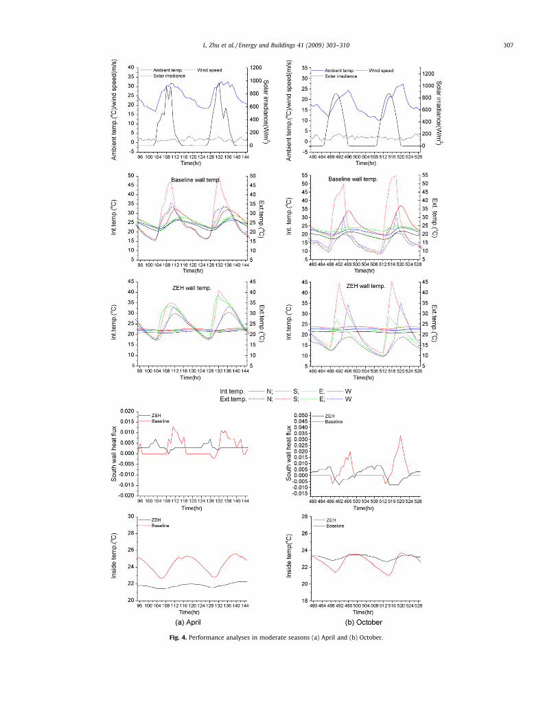
Fig. 4. Performance analyses in moderate seasons (a) April and (b) October.
L. Zhu et al. / Energy and Buildings 41 (2009) 303–310 307
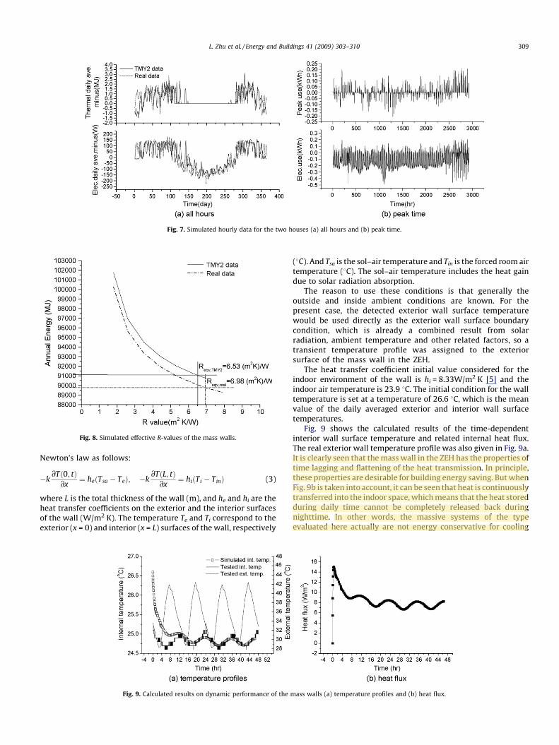
influence is clearly shown in Fig. 7a when hourly values areplotted. In Las Vegas, with its typical desert climate, an importantelectrical energy issue is reducing high demands for air condition-ing in summer. The simulated data during peak demand time(1 p.m. to 7 p.m., June 1 to September 30)were examined closely tosee if the effects of T-MassTM walls on peak usage are still negative.From Fig. 7b it is seen that the positive value is larger than thenegative and the overall energy usage for the mass wall houseduring peak time is 14 kWh less compared to the baseline house.So, in comparison with the traditional wood framing walls, theability of storing heat during peak time of the mass walls isfavorable for peak electricity saving but the remaining heat atnights is not beneficial for the total cooling energy usage.
7. Effective R-values and DBMS of mass walls
In the approach developed in [14–17] for massive systems, anequivalent R-value for the dynamic thermal performance wasderived. The effective R-value for massive systems is defined as thesteady-state R-value for conventional wall constructions when thecorresponding house has the same total building heating/cooling
load as that of the house that has the high mass construction. Theheating/cooling loads required for the house with mass walls wereused to estimate the effective R-value in conventional wood-framed houses. Various steady-state R-values forwood framewallswere set to achieve the heating/cooling loads shown as curves inFig. 8 where one set of data represents TMY2 data and the otheruses actual climate data. The equivalent R-values of themass wallsused in the ZEH were obtained when the lines were drawn fromcorresponding total building load to intersect the curves. Since thedynamic R-value is a function of climate conditions, the equivalentR-value from the simulations using TMY2 data is 6.53 (m2 8C)/Wwhile the corresponding value using actual data is 6.98 (m2 8C)/W.In accordance to the following equation:
DBMS " Reqv 1=R; (1)
where Reqv is the R-value equivalent for mass walls and R is thecorresponding steady-state value. The DBMS value is 3.17 usingTMY2 data while the value found using actual data is 3.39. It ispointed out here that even if the equivalent R-value or DBMSproperty for massive systems is high, since these parameters aredefined in terms of total building loads, it is still desirable to thinkabout the applicability of constructions in desert areas.
8. Further verification by modeling
Since all the above thermal performance analyses of themassive walls were based on the real-time collected data of thetemperature and heat flux, which would probably be affected byother factors, like the solar heat coming through windows, furtherverification by mathematically modeling needs to be conducted. Aone-dimensional mathematical model was established on themass walls used in the ZEH to avoid the effects from other factors.Moreover, the validity of using the one-dimensional simplificationin the two simulation tools will be shown. The one-dimensional,transient heat conduction equation is as follows:
@t@t
" a@2t@x2
; (2)
where t is the wall temperature (8C), a is the thermal diffusivity ofthe whole wall construction (m/s2), and t is time (s). In order tosolve this equation, two boundary conditions and an initialcondition are required. Usually, the boundary conditions on bothsides of the wall are of the convection type and are determined by
Fig. 5. Comparisons between simulated and actual energy usage in baseline house (a) A/C use and (b) furnace use.
Fig. 6. Monthly energy usage comparisons between two houses of massive andconventional wall constructions.
L. Zhu et al. / Energy and Buildings 41 (2009) 303–310308
alwebb
alwebb
alwebb
alwebb
alwebb
alwebb
Newton’s law as follows:
#k@T$0; t%@x
" he$Tsa # Te%; #k@T$L; t%@x
" hi$Ti # Tin% (3)
where L is the total thickness of the wall (m), and he and hi are theheat transfer coefficients on the exterior and the interior surfacesof the wall (W/m2 K). The temperature Te and Ti correspond to theexterior (x = 0) and interior (x = L) surfaces of the wall, respectively
(8C). And Tsa is the sol–air temperature and Tin is the forced roomairtemperature (8C). The sol–air temperature includes the heat gaindue to solar radiation absorption.
The reason to use these conditions is that generally theoutside and inside ambient conditions are known. For thepresent case, the detected exterior wall surface temperaturewould be used directly as the exterior wall surface boundarycondition, which is already a combined result from solarradiation, ambient temperature and other related factors, so atransient temperature profile was assigned to the exteriorsurface of the mass wall in the ZEH.
The heat transfer coefficient initial value considered for theindoor environment of the wall is hi = 8.33W/m2 K [5] and theindoor air temperature is 23.9 8C. The initial condition for the walltemperature is set at a temperature of 26.6 8C, which is the meanvalue of the daily averaged exterior and interior wall surfacetemperatures.
Fig. 9 shows the calculated results of the time-dependentinterior wall surface temperature and related internal heat flux.The real exterior wall temperature profile was also given in Fig. 9a.It is clearly seen that themass wall in the ZEH has the properties oftime lagging and flattening of the heat transmission. In principle,these properties are desirable for building energy saving. But whenFig. 9b is taken into account, it can be seen that heat is continuouslytransferred into the indoor space, whichmeans that the heat storedduring daily time cannot be completely released back duringnighttime. In other words, the massive systems of the typeevaluated here actually are not energy conservative for cooling
Fig. 7. Simulated hourly data for the two houses (a) all hours and (b) peak time.
Fig. 8. Simulated effective R-values of the mass walls.
Fig. 9. Calculated results on dynamic performance of the mass walls (a) temperature profiles and (b) heat flux.
L. Zhu et al. / Energy and Buildings 41 (2009) 303–310 309
alwebb
alwebb
alwebb
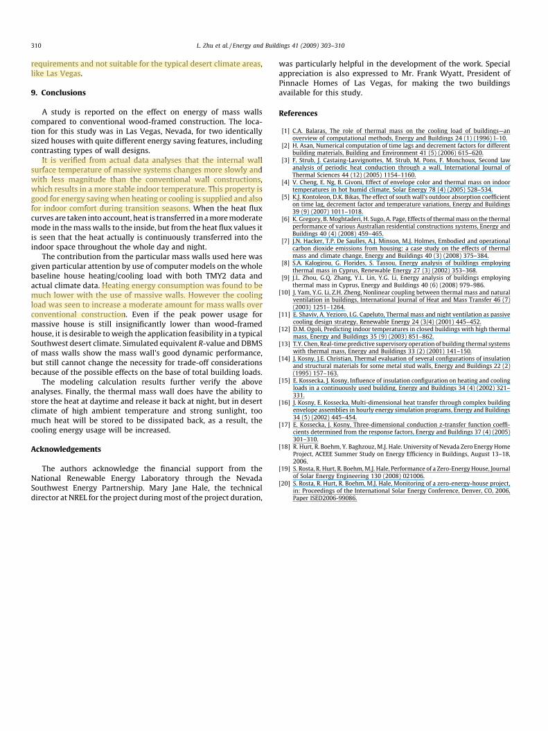
requirements and not suitable for the typical desert climate areas,like Las Vegas.
9. Conclusions
A study is reported on the effect on energy of mass wallscompared to conventional wood-framed construction. The loca-tion for this study was in Las Vegas, Nevada, for two identicallysized houses with quite different energy saving features, includingcontrasting types of wall designs.
It is verified from actual data analyses that the internal wallsurface temperature of massive systems changes more slowly andwith less magnitude than the conventional wall constructions,which results in a more stable indoor temperature. This property isgood for energy saving when heating or cooling is supplied and alsofor indoor comfort during transition seasons. When the heat fluxcurves are taken into account, heat is transferred inamoremoderatemode in themasswalls to the inside, but from the heat flux values itis seen that the heat actually is continuously transferred into theindoor space throughout the whole day and night.
The contribution from the particular mass walls used here wasgiven particular attention by use of computermodels on the wholebaseline house heating/cooling load with both TMY2 data andactual climate data. Heating energy consumption was found to bemuch lower with the use of massive walls. However the coolingload was seen to increase a moderate amount for mass walls overconventional construction. Even if the peak power usage formassive house is still insignificantly lower than wood-framedhouse, it is desirable to weigh the application feasibility in a typicalSouthwest desert climate. Simulated equivalent R-value and DBMSof mass walls show the mass wall’s good dynamic performance,but still cannot change the necessity for trade-off considerationsbecause of the possible effects on the base of total building loads.
The modeling calculation results further verify the aboveanalyses. Finally, the thermal mass wall does have the ability tostore the heat at daytime and release it back at night, but in desertclimate of high ambient temperature and strong sunlight, toomuch heat will be stored to be dissipated back, as a result, thecooling energy usage will be increased.
Acknowledgements
The authors acknowledge the financial support from theNational Renewable Energy Laboratory through the NevadaSouthwest Energy Partnership. Mary Jane Hale, the technicaldirector at NREL for the project duringmost of the project duration,
was particularly helpful in the development of the work. Specialappreciation is also expressed to Mr. Frank Wyatt, President ofPinnacle Homes of Las Vegas, for making the two buildingsavailable for this study.
References
[1] C.A. Balaras, The role of thermal mass on the cooling load of buildings—anoverview of computational methods, Energy and Buildings 24 (1) (1996) l–10.
[2] H. Asan, Numerical computation of time lags and decrement factors for differentbuilding materials, Building and Environment 41 (5) (2006) 615–620.
[3] F. Strub, J. Castaing-Lasvignottes, M. Strub, M. Pons, F. Monchoux, Second lawanalysis of periodic heat conduction through a wall, International Journal ofThermal Sciences 44 (12) (2005) 1154–1160.
[4] V. Cheng, E. Ng, B. Givoni, Effect of envelope color and thermal mass on indoortemperatures in hot humid climate, Solar Energy 78 (4) (2005) 528–534.
[5] K.J. Kontoleon, D.K. Bikas, The effect of south wall’s outdoor absorption coefficienton time lag, decrement factor and temperature variations, Energy and Buildings39 (9) (2007) 1011–1018.
[6] K. Gregory, B. Moghtaderi, H. Sugo, A. Page, Effects of thermalmass on the thermalperformance of various Australian residential constructions systems, Energy andBuildings 40 (4) (2008) 459–465.
[7] J.N. Hacker, T.P. De Saulles, A.J. Minson, M.J. Holmes, Embodied and operationalcarbon dioxide emissions from housing: a case study on the effects of thermalmass and climate change, Energy and Buildings 40 (3) (2008) 375–384.
[8] S.A. Kalogirou, G. Florides, S. Tassou, Energy analysis of buildings employingthermal mass in Cyprus, Renewable Energy 27 (3) (2002) 353–368.
[9] J.L. Zhou, G.Q. Zhang, Y.L. Lin, Y.G. Li, Energy analysis of buildings employingthermal mass in Cyprus, Energy and Buildings 40 (6) (2008) 979–986.
[10] J. Yam, Y.G. Li, Z.H. Zheng, Nonlinear coupling between thermal mass and naturalventilation in buildings, International Journal of Heat and Mass Transfer 46 (7)(2003) 1251–1264.
[11] E. Shaviv, A. Yezioro, I.G. Capeluto, Thermal mass and night ventilation as passivecooling design strategy, Renewable Energy 24 (3/4) (2001) 445–452.
[12] D.M. Ogoli, Predicting indoor temperatures in closed buildings with high thermalmass, Energy and Buildings 35 (9) (2003) 851–862.
[13] T.Y. Chen, Real-time predictive supervisory operation of building thermal systemswith thermal mass, Energy and Buildings 33 (2) (2001) 141–150.
[14] J. Kosny, J.E. Christian, Thermal evaluation of several configurations of insulationand structural materials for some metal stud walls, Energy and Buildings 22 (2)(1995) 157–163.
[15] E. Kossecka, J. Kosny, Influence of insulation configuration on heating and coolingloads in a continuously used building, Energy and Buildings 34 (4) (2002) 321–331.
[16] J. Kosny, E. Kossecka, Multi-dimensional heat transfer through complex buildingenvelope assemblies in hourly energy simulation programs, Energy and Buildings34 (5) (2002) 445–454.
[17] E. Kossecka, J. Kosny, Three-dimensional conduction z-transfer function coeffi-cients determined from the response factors, Energy and Buildings 37 (4) (2005)301–310.
[18] R. Hurt, R. Boehm, Y. Baghzouz, M.J. Hale. University of Nevada Zero Energy HomeProject, ACEEE Summer Study on Energy Efficiency in Buildings, August 13–18,2006.
[19] S. Rosta, R. Hurt, R. Boehm,M.J. Hale, Performance of a Zero-Energy House, Journalof Solar Energy Engineering 130 (2008) 021006.
[20] S. Rosta, R. Hurt, R. Boehm, M.J. Hale, Monitoring of a zero-energy-house project,in: Proceedings of the International Solar Energy Conference, Denver, CO, 2006,Paper ISED2006-99086.
L. Zhu et al. / Energy and Buildings 41 (2009) 303–310310
alwebb
alwebb
alwebb