
Product End User License Agreement - TIBCO Product Documentation
Upload
khangminh22Category
view
1download
0
DeskPack PowerTrapper 16
User Manual
10 - 2016

DeskPack PowerTrapper
ii
Contents1. Copyright Notice........................................................................................................................................4
2. About DeskPack PowerTrapper.............................................................................................................. 6
3. Data Exchange............................................................................................................................................73.1 Introduction to Data Exchange......................................................................................................... 7
3.1.1 Data Exchange Preferences.................................................................................................... 73.2 The PDF Export Plug-In......................................................................................................................7
3.2.1 Introduction.............................................................................................................................. 73.2.2 Saving a File as Normalized PDF............................................................................................ 83.2.3 Linked ArtiosCAD Graphics................................................................................................... 16
3.3 The Ink Manager Plug-in................................................................................................................. 173.3.1 Using the Ink Manager palette.............................................................................................173.3.2 Ink Options............................................................................................................................. 183.3.3 The Ink Manager flyout menu..............................................................................................193.3.4 Printing Method..................................................................................................................... 213.3.5 Job Setup................................................................................................................................ 223.3.6 Ink Manager Preferences...................................................................................................... 233.3.7 Known limitations.................................................................................................................. 24
3.4 The Structural Design Plug-in......................................................................................................... 253.4.1 Introduction............................................................................................................................ 253.4.2 Structural Design Import.......................................................................................................253.4.3 Structural Design Export....................................................................................................... 37
3.5 The Page Box Plug-in.......................................................................................................................523.5.1 Introduction............................................................................................................................ 523.5.2 Trim Box and Media Box.......................................................................................................523.5.3 All Page Boxes........................................................................................................................56
3.6 The Inspection Setup Plug-In.......................................................................................................... 573.6.1 Adding and changing Inspection points.............................................................................. 583.6.2 Adding and changing Inspection boxes...............................................................................593.6.3 Dynamic Art Placeholders.....................................................................................................593.6.4 Import and Export................................................................................................................. 59
3.7 Messages...........................................................................................................................................603.7.1 The Messages Palette............................................................................................................603.7.2 Filtering the Messages...........................................................................................................613.7.3 Saving the Messages............................................................................................................. 623.7.4 Clearing the Messages.......................................................................................................... 63
3.8 Esko Document Setup..................................................................................................................... 633.8.1 Distortion................................................................................................................................ 633.8.2 Screen Registration................................................................................................................63

Contents
iii
3.9 Annotations.......................................................................................................................................643.9.1 Loading XFDF files..................................................................................................................643.9.2 The Annotations palette........................................................................................................653.9.3 Multipage PDF files with Annotations..................................................................................663.9.4 Updating................................................................................................................................. 66
4. PowerTrapper for Adobe Illustrator.................................................................................................... 674.1 Introduction to PowerTrapper Standalone.................................................................................... 67
4.1.1 What is Trapping?.................................................................................................................. 674.1.2 What is PowerTrapper Standalone?..................................................................................... 68
4.2 Trapping with PowerTrapper Standalone...................................................................................... 684.2.1 The Trap Dialog......................................................................................................................704.2.2 The Trap Layer....................................................................................................................... 844.2.3 The Trap Select Tool.............................................................................................................. 844.2.4 The Color Pairs Palette..........................................................................................................85
4.3 Selective Trapping............................................................................................................................ 904.4 Add Rich Black..................................................................................................................................904.5 PowerTrapper Preferences.............................................................................................................. 91
5. White Underprint.................................................................................................................................... 945.1 White Underprint............................................................................................................................. 945.2 Adding and Removing White Underprint.......................................................................................945.3 White Underprint settings...............................................................................................................955.4 White Underprint Ink.......................................................................................................................965.5 Include White Objects......................................................................................................................96

1 DeskPack PowerTrapper
4
1. Copyright Notice© Copyright 2016 Esko Software BVBA, Gent, Belgium
All rights reserved. This material, information and instructions for use contained herein arethe property of Esko Software BVBA. The material, information and instructions are providedon an AS IS basis without warranty of any kind. There are no warranties granted or extendedby this document. Furthermore Esko Software BVBA does not warrant, guarantee or make anyrepresentations regarding the use, or the results of the use of the software or the informationcontained herein. Esko Software BVBA shall not be liable for any direct, indirect, consequentialor incidental damages arising out of the use or inability to use the software or the informationcontained herein.
The information contained herein is subject to change without notice. Revisions may be issuedfrom time to time to advise of such changes and/or additions.
No part of this document may be reproduced, stored in a data base or retrieval system,or published, in any form or in any way, electronically, mechanically, by print, photoprint,microfilm or any other means without prior written permission from Esko Software BVBA.
This document supersedes all previous dated versions.
PANTONE®, PantoneLIVE and other Pantone trademarks are the property of Pantone LLC.
All other trademarks or registered trademarks are the property of their respective owners.Pantone is a wholly owned subsidiary of X-Rite, Incorporated. © Pantone LLC, 2015. All rightsreserved.
This software is based in part on the work of the Independent JPEG Group.
Portions of this software are copyright © 1996-2002 The FreeType Project (www.freetype.org).All rights reserved.
Portions of this software are copyright 2006 Feeling Software, copyright 2005-2006 AutodeskMedia Entertainment.
Portions of this software are copyright ©1998-2003 Daniel Veillard. All rights reserved.
Portions of this software are copyright ©1999-2006 The Botan Project. All rights reserved.
Part of the software embedded in this product is gSOAP software. Portions created by gSOAPare Copyright ©2001-2004 Robert A. van Engelen, Genivia inc. All rights reserved.
Portions of this software are copyright ©1998-2008 The OpenSSL Project and ©1995-1998 EricYoung ([email protected]). All rights reserved.
This product includes software developed by the Apache Software Foundation (http://www.apache.org/).
Adobe, the Adobe logo, Acrobat, the Acrobat logo, Adobe Creative Suite, Illustrator, InDesign,PDF, Photoshop, PostScript, XMP and the Powered by XMP logo are either registeredtrademarks or trademarks of Adobe Systems Incorporated in the United States and/or othercountries.
Microsoft and the Microsoft logo are registered trademarks of Microsoft Corporation in theUnited States and other countries.
SolidWorks is a registered trademark of SolidWorks Corporation.
Portions of this software are owned by Spatial Corp. 1986 2003. All Rights Reserved.

1DeskPack PowerTrapper
5
JDF and the JDF logo are trademarks of the CIP4 Organisation. Copyright 2001 The InternationalCooperation for the Integration of Processes in Prepress, Press and Postpress (CIP4). All rightsreserved.
The Esko software contains the RSA Data Security, Inc. MD5 Message-Digest Algorithm.
Java and all Java-based trademarks and logos are trademarks or registered trademarks of SunMicrosystems in the U.S. and other countries.
Part of this software uses technology by Best Color Technology (EFI). EFI and Bestcolor areregistered trademarks of Electronics For Imaging GmbH in the U.S. Patent and TrademarkOffice.
Contains PowerNest library Copyrighted and Licensed by Alma, 2005 – 2007.
Part of this software uses technology by Global Vision. ArtProof and ScanProof are registeredtrademarks of Global Vision Inc.
All other product names are trademarks or registered trademarks of their respective owners.
Correspondence regarding this publication should be forwarded to:
Esko Software BVBA
Kortrijksesteenweg 1095
B – 9051 Gent

2 DeskPack PowerTrapper
6
2. About DeskPack PowerTrapperThe ‘DeskPack PowerTrapper for Illustrator’ bundle offers dedicated trapping functionality,combined with the ability to add White Underprint.
It combines the following plug-ins:
• Data Exchange on page 7 (Free)
• PowerTrapper for Adobe Illustrator on page 67
• White Underprint on page 94

3DeskPack PowerTrapper
7
3. Data Exchange
3.1 Introduction to Data ExchangeThe Esko Data Exchange plug-in for Adobe
® Illustrator
® combines several plug-ins into one
package for easier installation. The combined plug-ins are:
• The PDF Export Plug-In on page 7
• The Structural Design Plug-in on page 25
• The Ink Manager Plug-in on page 17
• The Page Box Plug-in on page 52
• Messages on page 60
• The WebCenter Connector Plug-In
Along with a combined installation, there are new features in the updated plug-ins:
• Support for OPI (Open Press Interface) server mapping in PDF Export
• A combined Preferences dialog for PDF Export, and TrimBox/MediaBox that also workswith Shuttle and Launch Task in client-server configurations
• The ability to always save (or not save) XMP data in Illustrator documents when you savethem.
• Esko Document Setup
3.1.1 Data Exchange Preferences
Update XMP on Document Save directly on the Preferences > Esko menu controls if thedocument’s XMP data is updated when the document is saved in the .AI format or as AdobePDF with preserved Illustrator editing capabilities, and is turned on by default. Deselecting thisoption results in slightly faster document saves
3.2 The PDF Export Plug-In
3.2.1 Introduction
The PDF Export plug-in allows you to directly export your Illustrator files to the NormalizedPDF format.

3 DeskPack PowerTrapper
8
The Normalized PDF format contains all the Esko metadata necessary to ensure compatibilitywith your Esko workflow:
• list of linked images,
• barcode information,
• placed CAD graphics metadata,
• inks information,
... and other document properties.
3.2.2 Saving a File as Normalized PDF
To save your Illustrator file as Normalized PDF using PDF Export:
1. Go to File > Export...2. In the dialog that opens, choose your file’s name and location, and choose the Normalized
PDF (pdf) format.
3. Click Export.4. In the PDF Export Settings dialog that opens, fill in the export settings (see PDF Export
Settings on page 8).5. Click OK to export the file.
PDF Export SettingsWhen exporting your files to the Normalized PDF format, you need to set the PDF ExportSettings.

3DeskPack PowerTrapper
9
Preset
Using Presets you can store and reuse the settings for the PDF Export dialog.
You can save the current settings as a Preset by selecting Save... and entering a name. Thelocation for the Presets is defined in the PDF Export Preferences. See PDF Export Preferences onpage 16
You can load a Preset by selecting it in the dropdown.
If you set the Preset to Default, the parameters as set in the PDF Export Preferences will beused. See PDF Export Preferences on page 16.
If the current settings are not saved as a setting, the Preset dropdown will show "Custom".
Images and Linked Files
1. In the Images and Linked Files group, choose to either Embed Images in the NormalizedPDF, or Save Links to the images.
• If you choose to embed the images, you don’t have any more preferences to fill in andyou can just click OK.
Note: This doesn’t save the images’ link information (except for linked ArtiosCADgraphics, see Linked ArtiosCAD Graphics on page 16).
• If you choose to use linked images, fill in the other preferences of the dialog.

3 DeskPack PowerTrapper
10
2. Enable Add Preview (max 72 DPI) if you want your Normalized PDF to have a lowresolution preview of the linked images.
This preview allows you to view the linked images when opening your file in Acrobat™ forexample.
3. Choose where to copy the linked images:
• Choose Copy Images Next To Output File to copy them next to the folder in which youwill save the Normalized PDF (so other applications like ArtPro or PackEdge can stillopen them when the links are broken).
• Choose Use Links And Apply Server Mapping to keep the images where they are butupdate the links (for example if the images are in a shared folder located on a differentmachine).
4. When choosing Use Links And Apply Server Mapping, fill in a Server Mapping if the sharenames on the client machine and on the other server do not match.a) When checked, Copy Links If Not On File Servers verifies if linked images are already
on fileservers and if they are not, copies them along with the exported Normalized PDFfile. Choosing this option also enables the File Servers... button where you add themachines that store linked images so that Esko workflow servers can find them.
For more information, see What is a Server Mapping? and Adding a Server Mapping.
OPI and Server MappingWhen you click Settings in the OPI and Server Mapping group of the PDF ExportPreferences dialog of Data Exchange Preferences, the OPI and Server Mapping dialogappears:

3DeskPack PowerTrapper
11
Note:
This dialog is available only when you have chosen to Save Links in exported NormalizedPDF files. When you export a Normalized PDF, OPI Mapping is applied first and then ServerMapping.
ServersThe top pane of the dialog configures Server Mappings. You need to use Server Mappingswhen the Normalized PDF you output:
• has linked images that are located on a different machine (file server),• will be used on another machine (not your local machine or the file server).
Server Mappings allow you to map the image links from one share name to anotherautomatically on output. This ensures that the links are not broken when the Normalized PDFis used on another machine.
For example:
• the linked images are saved on a file server called “Server”, in a shared folder called“Images”,
• your copy of Illustrator with PDF Export is on a Mac, and the shared folder containing theimages is mounted as “Hi-Res_Images”.
• the Normalized PDF you export will be used on a PC, where the shared folder containingthe images is mounted as “Shared_Images”.
The link to an image called “My_Image.psd” is “Server/Hi-Res_Images/My_Image.psd”on the Mac, and should be “\\Server\Shared_Images\My_Image.psd” on the PC.

3 DeskPack PowerTrapper
12
When adding the Server Mapping in the OPI And Server Mapping dialog, you should enterthe Share Details as follows by:
• name of the file server in Server Name,• name of the shared folder containing the images as seen from your local Mac in Local
Share,• name of the shared folder containing the images as seen from the other PC in Server
Share.
Note:
• You can use subfolders in a Server Mapping.
• You can also use Server Mappings to replace images (for example to swap low-resolution
for high-resolution images when the low-resolution and high-resolution images haveidentical separations).
To add the Server Mapping, do the following:
1. In the OPI And Server Mapping dialog, click the plus sign button to the lower left of theServers pane. This opens the Share Details dialog.

3DeskPack PowerTrapper
13
2. Enter or choose the name of the file server containing your linked images in Server Name.3. Enter or choose the name of the file server’s share containing your linked images as it
appears on your local machine in Local Share.4. Enter the name of the file server’s share containing your linked images as it appears on
the other machine that will use your Normalized PDF in Server Share.
5. If you want to add another Server Mapping (to use your Normalized PDF on yet another
machine), repeat steps 1 to 4.
To edit a Server Mapping, double-click it. To remove a Server Mapping, select it and click theminus button to the lower left of the Servers pane.
OPI MappingThe lower half of the OPI And Server Mapping dialog configures OPI Mapping, which definesthe rules for image substitution when exporting a Normalized PDF in a more specific way thanServer Mapping. OPI stands for Open Press Interface.
To add an OPI mapping, do the following:
1. Click the plus sign to the lower left of the list pane. This opens the OPI Rule Editor dialog.

3 DeskPack PowerTrapper
14
2. After the word If, decide how many conditions that must be true for this mapping rule to
take effect: All, Any, or None.3. For the condition In the top pane of the dialog, choose the element of the image file’s path
to examine in the first field. Image paths are in URI (Uniform Resource Identifier) format,such as file://mymac/MacHD/images/lowres/tests/Spacebar_CMYK.eps. As youselect elements, further controls appear on the same line to refine the condition. Forexample, if you choose Full Path Is, you can click ... to browse for a folder, or click x to revertto the previous folder. To add a condition, click +; to remove a condition, click -.
4. Once you have defined the conditions, define the changes to the path in the lower paneof the window. Use the same process to define the changes as you did to define theconditions: choose the change, then set its options on the same line. To add a change, click+; to remove a change, click -.
5. Click OK to finish defining the rule.6. To add another rule, click +; to remove a rule, click -.
Consider again this example URI file name: file://ImageServer/LOWRES/images/lowres/tests/Spacebar_CMYK.eps.
• The condition Extension, Is Equal To, EPS will match.• Folder Name, Starts With, lowres/ will match. You can specify the text ending with / to
state that it must be the entire Folder name and to make sure that directories starting with(for example) lowres plus/ will not match.
• Server Name, Is Equal To, imageserver will also match as the case is not compared.
When you use more than one condition in a rule, the Replace 1st Matching Part Of Path andReplace 2nd Part Of Matching Path changes become effective.
Consider this file: file://Serv/SharedImg/LORESIMAGES/ANIMALS/LOWRES/myimage.eps
• with conditions of Folder Name, Contains, LORESIMAGES, and Folder Name, Contains,LOWRES.

3DeskPack PowerTrapper
15
• and changes of Replace 1st Matching Part Of Path, HIGHRESIMAGES, and Replace 2ndPart Of Matching Path, HIGHRES.
The first change will replace LOWRESIMAGES with HIGHRESIMAGES (since it was first), and thesecond change will replace LOWRES with HIGHRES.
Notes and RestrictionsTo copy the OPI settings between computers so they all are the same, copy AE10-OPISettings.prefs. In Windows, that file can be at C:\Documents and Settings\username\AppData\Roaming\Adobe\Adobe Illustrator CSx Settings, but its exactlocation depends on the type of login (local or domain) and Illustrator version (CSx where x isa number). On the Mac, this file is normally in Users/username/Library/Preferences/Adobe illustrator CSx Settings/. Copy the file to the same location on the targetmachines.
There are a few restrictions when using OPI Mapping:
• The high-resolution images must be accessible from the client workstation.
• Ink Manager will not show extra inks that are present in the high-resolution images.• When exporting the file using Shuttle, only the inks from Ink Manager are shown, not any
extra ones present in the high-resolution images.
• PDF Export, Viewer for Illustrator, and PowerTrapper Client and Standalone will use thehigh-resolution images and will know about any extra inks.
Trim Box and Other Settings
Trim BoxIn the Trim Box (Borders) group of the PDF Export Preferences dialog, the Trim Box(Borders) drop-down list lets you choose how the edge of the exported PDF file is chosen:using the Trim Box from Document, using the Current Artboard, or by using the ArtworkBounding Box.
Fit Media Box to Artwork expands or shrinks the Media Box as appropriate.
OtherOutline All Text converts all text to outlines.
Include Hidden Objects and Layers includes hidden objects when the PDF file is exported.
Include Notes allows to include annotations in the PDF. This option is only available incombination with the PDF Import plug-in.
If Expand Patterns is selected, patterns will be replaced by actual objects. The path containingthe pattern fill, will then be filled with the objects as defined in the pattern.
Contourize Bitmaps will convert 1-bit images (linked or embedded) into vectors.
Convert Blended Objects to Images will convert blended objects to images. You can set theresolution for this images to High (600dpi), Medium (300dpi) or Low (150dpi)
Note: In case of converting blended objects with different oveprint setting (one is overprinting,the other is not), the convertion might change the final result. The following message is shown:"Rasterized Blend combines art in overprint and not in overprint mode. Rasterization may havecaused changed appearance."

3 DeskPack PowerTrapper
16
PDF Export PreferencesYou can open the PDF Export Preferences by choosing Illustrator > Preferences > Esko > PDFExport Preferences
The main part of the Preferences contain the same settings as the PDF Export Settings. Thesesettings will be used if the "Default" preset is selected. See:
• Images and Linked Files on page 9• OPI and Server Mapping on page 10• Trim Box and Other Settings on page 15
The PDF Export Preset Settings Folder defines the location where the Presets are saved:either the Default Preference Folder, or a custom folder you can select by clicking the Browse...button. See also Preset on page 9
3.2.3 Linked ArtiosCAD Graphics
When you export a document with linked ArtiosCAD graphics to Normalized PDF, the graphicsare treated slightly differently:

3DeskPack PowerTrapper
17
When choosing “Embed Images” in the Preferences:
• The ArtiosCAD graphics are embedded in your Normalized PDF.• The original link information is saved in your Normalized PDF.
When choosing “Save Links” in the Preferences:
• The ArtiosCAD graphics are embedded in your Normalized PDF.• They are also copied to the location you define: Next To Output File or on another server
(according to a Server Mapping if defined).• The link to the copied graphics is saved in your Normalized PDF.
3.3 The Ink Manager Plug-in
3.3.1 Using the Ink Manager palette
The Ink Manager palette is a powerful pre-press color editing and proofing tool. Easily identifywhere Pantone colors are used within a document or where custom spot colors can be found,then convert these colors to a custom spot color or to process colors.
The Ink Manager palette also allows you to specify crucial ink parameters such as the ink type,angle and lineature. Once defined, these parameters are saved inside the Illustrator document.
Note:
Screening for Illustrator allows you to make exceptions to these ink parameters. WithScreening for Illustrator objects can have different settings for ruling, angle and dotshape.Please refer to the Screening for Illustrator documentation for more information.
To use the Ink Manager palette, choose Window > Esko > Ink Manager . The Ink Managerpalette appears.
Delete Ink Variant. To delete an Ink Variant made with Screening for Illustrator, selectthe ink variant which needs to be removed and click the 'Delete Ink Variant' button. The objectswill get the ink settings of the parent ink.
Refresh. To update the lists of inks used within your document, click the Refresh button.After modifying a document, click the refresh button to update the list of used inks.
3 DeskPack PowerTrapper
18
Select. To identify objects containing specific inks within a job, select the ink you wish tosearch for and click the 'Select' button. It is possible to select more than one ink at a time.
Convert to Other. To convert a selected ink from your document Ink list to another ink,click 'Convert to other'. More than one ink can be selected at a time.
Note:
Converting an ink will affect only line art. However, if you have the Channel Mapping or ColorEngine plug-in installed and licensed, converting an ink will also result in the correspondingchannel mapping for all images. See the Channel Mapping documentation for moreinformation.
Convert to CMYK. To convert a selected Spot Color from your document Ink list to aProcess Color Mix, CMYK, click 'Convert to CMYK'. More than one ink can be selected at a time.
Note:
Convert to Other and Convert to CMYK are only available if you have a license for boostX,Channel Mapping or Color Engine Plugin.
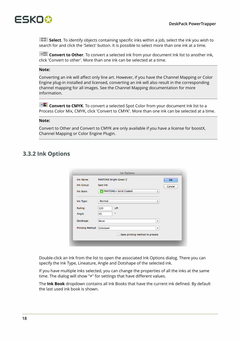
3.3.2 Ink Options
Double-click an Ink from the list to open the associated Ink Options dialog. There you canspecify the Ink Type, Lineature, Angle and Dotshape of the selected ink.
If you have multiple inks selected, you can change the properties of all the inks at the sametime. The dialog will show "≠" for settings that have different values.
The Ink Book dropdown contains all Ink Books that have the current ink defined. By defaultthe last used ink book is shown.

3DeskPack PowerTrapper
19
Available Ink Types are: Normal, Opaque, Varnish and Technical. The ink type for processinks cannot be changed. The ink type is always normal. The following Pantone inks are alwaysopaque inks: Pantone 8003 C, Pantone 8021 C, Pantone 8062 C, Pantone 8100 C, Pantone 8201C, Pantone 8281 C, Pantone 8321 C, Pantone 871 C, Pantone 872 C, Pantone 873 C, Pantone874 C, Pantone 875 C, Pantone 876 C, Pantone 877 C. The ink type of these inks cannot bechanged.
Note: If you change an Ink to Technical or Opaque, the ink will be moved to the bottom ofthe Ink list. If you change the ink order afterwards, this new order will be respected.
Dotshape shows a list of all dotshapes available for the FlexRip. However, it is possible to enterany dot that is available on your rip instead of the proposed dotshapes. Only use a dotshapethat is installed on the rip that will be used to expose the document.
Note: Entering a dotshape is not compatible with Nexus RIP.
These Ink options are stored in the Illustrator document and are used by other DeskPackplug-ins like PowerTrapper Client, PowerLayout Client, etc. For example, PowerTrapper Clientwill ignore varnish and technical inks and will take the opaqueness of inks in account whendetermining trap directions.
You can define the Printing Method. See Printing Method on page 21
Note:
Global swatches cannot be converted.
3.3.3 The Ink Manager flyout menu
• Ink Options... opens the ink options dialog.
• Convert Ink to... has the same functionality as the 'Convert to Other' button

3 DeskPack PowerTrapper
20
• Convert Ink to CMYK has the same functionality as the 'Convert to CMYK' button • Convert all Spot Inks to CMYK converts all the spot inks in the document to their CMYK
equivalent.
Note:
Keep in mind that this function will also convert white objects created by the WhiteUnderprint plugin, using a special spot ink.
• Update Ink list refreshes the ink list.• Process Inks In Images… The plug-in uses Illustrator to determine which inks are used in
external images. Illustrator has some limitations:
• With linked EPS images it is not possible to detect whether CMYK was used in the linkedimage. Ink Manager will assume that CMYK is present in the linked EPS images, unlessthe user has specified otherwise.
• TIFF images with spot channels always have CMYK channels, even if those channels areempty.
So with externally linked images, the plug-in doesn’t really know whether CMYK is used.“Process Inks in Images” offers a manual solution. If you click this option, the “Process Inksin Images” dialog box appears:
By default all toggles are switched on, which means that the plug-in will assume thatexternal images contain cyan, magenta, yellow and black.
If you know that there is no cyan in the externally placed images, you can switch ProcessCyan off. Click 'Apply' and at the bottom of the Ink Manager the indication “Disabled inImages: C” will appear.
The plug-in will assume that only magenta, yellow and black were used in the externallyplaced images. If cyan is used in other objects of the document, it will be listed in inkmanager.
• Using Display Columns you can set what columns of the Ink Manager should be shown:the Ink Type, Ink Book, Screening Details (LPI, Angle and dotshape), Printing Method (seePrinting Method on page 21) and Job Setup (see Job Setup on page 22)
• Reverse Ink Order will turn the order of the inks upside down.• By default, the process colors are in Cyan - Magenta - Yellow - Black order. If you change
this order and apply Save CMYK Ink Order as Default, the changed order will be used

3DeskPack PowerTrapper
21
as default order. By selecting Restore Default CMYK order, the original default order isrestored.
• By using Sort Light To Dark or Sort Dark To Light, you can rearrange the order of inksbased on the luminocity. Note that Opaque and Technical inks are placed at the bottom ofthe list, but also sorted light to dark or dark to light.
• If you have to reuse the same Ink Parameters frequently, you can use Save Ink Preset ...to save all ink parameters, including Ink Name, Type, Ink Book, Ruling, Angle, Dotshape andPrinting Method. You can Load Ink Preset... to overwrite all ink parameters in the currentdocument with the parameters you saved earlier. You can set the location for the saved InkPresets in the Preferences. See Ink Manager Preferences on page 23
• By enabling Use Properties from Job Setup, the inks and ink parameters defined in the JobSetup will be enforced. See Job Setup on page 22
3.3.4 Printing Method
You can set the Printing Method for every ink.
The Printing Method information can be used in SmartNames, or for Automation Engine taskthat handle the printing method.
By default, the Printing Method column is hidden. By selecting Show Printing Method in thefly-out menu you can make it visible.
You can change the Printing Method in the Ink Manager palette.
You can select one of the predefined printing methods, or create a new printing method.
PresetsAs from version 12.1.2, when connected to an Automation Engine Server, the list of PrintingMethods is loaded from the Automation Engine server.
Note: This implies that Printing Methods saved in earlier versions of Deskpack are no longervisible and will need to be redefined.
Printing Methods can be saved in the Automation Engine Configure tool, or in the Ink Optionsby selecting Save to presets

3 DeskPack PowerTrapper
22
If there's no connection to an Automation Engine, the presets are saved locally in the AdobeIllustrator Preferences.
3.3.5 Job Setup
When a document is opened from an Automation Engine Job using File > Job Folder > Openfrom Job Folder ... , you can force Ink Manager to use the ink parameters defined in the JobSetup, overwriting the current Ink Paramters, by enabling Use Properties from Job Setup,
either from the fly-out menu or by clicking the button in the Ink Manager palette
The Job column will appear automatically. You can change its visibility under Display Columnsin the fly-out menu.
The column will give a status icon for every ink:
• : the ink is defined in the Job Setup. The parameters defined in the Job Setup will be
used.
• : the ink is not in the Job Setup but is used in the document
• : the ink is defined in the Job Setup but not used in the document. The line will be
greyed out, and have no number.
If Use Properties from Job Setup is enabled, the Ink Options dialog for inks defined in the JobSetup will show status icons for every paramter:
• : the parameter is taken from the Job Setup, so it can't be modified.

3DeskPack PowerTrapper
23
• : the parameter is not defined in the Job Setup, so it can be set freely.
3.3.6 Ink Manager Preferences
The Ink Manager Preferences can be opened from Illustrator > Preferences > Esko >Ink Manager Preferences... (Mac OS) or Edit > Preferences > Esko > Ink ManagerPreferences... (Windows)
In the Ink Manager Preferences, you can set the Default Values (angle and ruling) for CMYKinks.
You can also set the default angle and ruling to be used for new Spot inks. However, thesedefaults can be overruled when using a Spot ink that was used before, with a different Angleand Ruling value. The Angle and Ruling for all used spot inks are saved in the Preferences file
You can also define if inks that are only used in non-printable layers or hidden layers should beshown in the ink manager by setting the Show inks of non-printable layers and Show inks ofhidden layers option.
Note:
The Remap Ink functionallity also takes the Show inks of non-printable layers and Show inksof hidden layers option into account: When switched off, inks on non-printable or hiddenlayers will not be remapped.

3 DeskPack PowerTrapper
24
Enable Use ClassicColors Ink Book to use the ClassicColors Ink Book. When using aClassicColors Ink Book for your HP device, you can enable the Use ClassicColors Ink Bookoption, to avoid conflicts for inks using generic names, such as "White".
The Preferred Ink Book is the Ink book shown by default when opening the Add Ink from InkBook dialog.
You can set the location to store Ink Manager Preset Settings: either in the defaultpreferences folder, or in a custom folder you choose.
3.3.7 Known limitations
Since DeskPack Suite 10.1 Assembly 6 InkManager has been using different method for the inkconverting.
The new method uses Illustrator's Appearance allowing multiple fills and stroke in a singleobject instead of creating temporary inks (BG Inks). Beside many advantages it brings a coupleof limitations, having connection with the Illustrator limitations or behavior.
Re-mapping process inks to spot inks.As it is impossible to simply change one of the process inks to the spot ink, the only solutionis adding a new fill to the object with the new spot ink and use overprint to mix these fillstogether.
• Adding a brand new fill is not possible on text objects on the character level. Text objectsusing various inks on separate characters aren't mapped and an operator is warned.
• Re-mapping of process to spot inks on paths, using Effects on fill or stroke, will raise awarning, because adding a new fill could change the visual appearance.
Re-mapping inks in gradientsRe-mapping of the process ink to the spot ink generates a new fill due to the same reason asbefore.
• Let's have an example that the gradient already contains the target spot ink on one of itsstops and another stop contains the process color being transformed. The re-mapping oneof the process inks will add a new fill with the same gradient but with the target spot inkson the place of the process ink. In other cases the overprint will blend these two fills andproduce expected visual appearance. In this particular case Illustrator will not blend thesefills because both contain the same spot ink and Illustrator then ignores the overprint. Anoperator is informed about that.
• Similar issue comes when the object already contains two gradient fills. An operator is againwarned.

3DeskPack PowerTrapper
25
3.4 The Structural Design Plug-in
3.4.1 Introduction
Introducing Structural DesignStructural Design enables the Adobe Illustrator users to read in an ArtiosCAD ARD file, an Eskoflexible .bag file and/or a Collada .dae or .zae file. This structural design can then be alignedto the graphics and this alignment will be maintained in the rest of the Esko workflow (e.g.ArtiosCAD, Visualizer, PackEdge, ArtPro, Plato, RIPs). On top of that, you can create a varnishplate from the bleed outline, from the Illustrator artboard or from the bounding box of thestructure automatically excluding the coating free areas.
Structural Design Export allows an Adobe Illustrator user to export contours from Illustrator tonative ArtiosCAD .ard format. It also allows adding and modifying cutout windows to a loadedArtiosCAD file.
3.4.2 Structural Design Import
General PrinciplesThe Structural Design plug-in enables you to open or place structural design files inside AdobeIllustrator. The imported structural design files are linked to the Adobe Illustrator (.ai) files, butthey are not embedded. After opening or placing a structural design file, the file appears in theAdobe Illustrator layer palette. The structural design paths are special paths that cannot bemodified accidentally.By default the structural design layer and its sublayers will be locked. Youcan unlock the structural design layers. This enables you to select individual structural designpaths and use the illustrator alignment tools to align graphics to the structural design paths.
Open or Place an ARD, BAG, DAE, ZAE fileFrom Suite 10.0 onwards when the plug-in is present, a dedicated Place File showing onlyStructural Design files is found in the File menu. Choose File > Structural Design > PlaceFile....
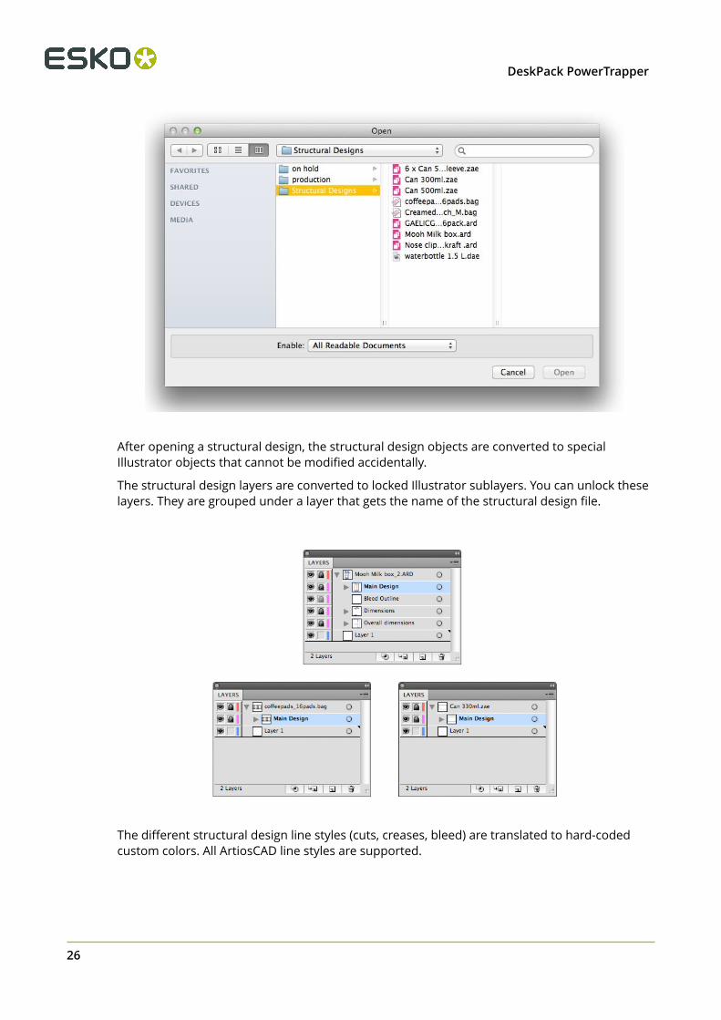
The appropriate file types also appear in the Illustrator Open and Place dialogs:
3 DeskPack PowerTrapper
26
After opening a structural design, the structural design objects are converted to specialIllustrator objects that cannot be modified accidentally.
The structural design layers are converted to locked Illustrator sublayers. You can unlock theselayers. They are grouped under a layer that gets the name of the structural design file.
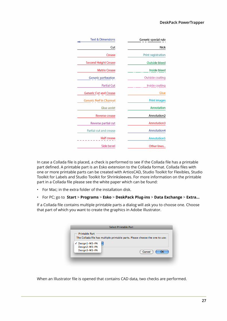
The different structural design line styles (cuts, creases, bleed) are translated to hard-codedcustom colors. All ArtiosCAD line styles are supported.
3DeskPack PowerTrapper
27
In case a Collada file is placed, a check is performed to see if the Collada file has a printablepart defined. A printable part is an Esko extension to the Collada format. Collada files withone or more printable parts can be created with ArtiosCAD, Studio Toolkit for Flexibles, StudioToolkit for Labels and Studio Toolkit for Shrinksleeves. For more information on the printablepart in a Collada file please see the white paper which can be found:
• For Mac; in the extra folder of the installation disk.
• For PC; go to Start > Programs > Esko > DeskPack Plug-ins > Data Exchange > Extra...
If a Collada file contains multiple printable parts a dialog will ask you to choose one. Choosethat part of which you want to create the graphics in Adobe Illustrator.
When an Illustrator file is opened that contains CAD data, two checks are performed.

3 DeskPack PowerTrapper
28
1. First of all, the plug-in checks whether the structural design file still can be found in itsoriginal place. If that is not the case, the plug-in will look for the structural design file in thesame directory where the Illustrator file is. If it finds the structural design file there, it willuse this structural design file instead, otherwise, you will be asked to browse to the newlocation of the file.
2. A second check is performed to see if the structural design file has been modified sinceit was originally embedded in this Illustrator file. If so, the Illustrator document will beupdated.
Placing a structural design file: If a structural design file is already loaded and you place anew structural design file, the new structural design file will replace the old structural designfile. This implies that you can never have more than one structural design file in an Illustratordocument.
The difference between placing and opening a structural design file: When opening astructural design file, the artboard will adopt the size of the bounding box of the structure.When placing a structural design file, the artboard will not be changed.
Open or Place from ShapesYou can open files from Shapes directly or place them into existing Illustrator files by using thecommands in File > Structural Design.

3DeskPack PowerTrapper
29
You can choose a new Shape to download and purchase from the store or you can use analready-downloaded Shape from the library on your computer. In order to access the Shapesstore, you must have already entered the Shapes server settings and your Shapes accountinformation in the Shapes Preferences dialog in Preferences > Esko > Shapes Preferences.
Opening and placing a file from Shapes follows the same general workflow. This example willshow you how to place a Shapes file.
1. In an open Illustrator document, click File > Structural Design > Place from Shapes.... TheShapes window appears in the state you last used it, either at your local computer’s ShapesLibrary or at the online Shapes Store.
2. If you want to use a new Shape, choose it and buy it. It gets downloaded to your local
machine’s Shapes Library.

3 DeskPack PowerTrapper
30
3. If you bought a new Shape, the Shapes window should switch to the Shapes Library
automatically. To use an existing Shape, click Library in the Shapes window. Select thedesired Shape and click Place.
4. The Shape is either placed in the open Illustrator document or opened as a new document.
Only the printable area of the Shape is visible in Illustrator. If you have one of the Studioproducts, use the Studio palette to view the Shape with the printable area.
Shown below is a white wine bottle from Shapes with the label designed in Illustrator and withthe 3D model shown in the Studio palette.

3DeskPack PowerTrapper
31
Update the Structural Design FileIf the structural design file has been modified while still editing the Illustrator file, an update ofthe Structural Design file can be forced. A dedicated Update for Structural Design files is foundin the File menu. Choose File > Structural Design > Update

3 DeskPack PowerTrapper
32
Align Structure and Graphics
Interactive Move Structural Design tool
3DeskPack PowerTrapper
33
The Move Structural Design tool has been added underneath the Illustrator select tool. Selectthis tool to move the structural design interactively without unlocking the structural designlayers. Hold down the mouse button and drag to move the structural design.
Tip:
If you choose View > Smart Guides, the structural design will snap to the graphics.
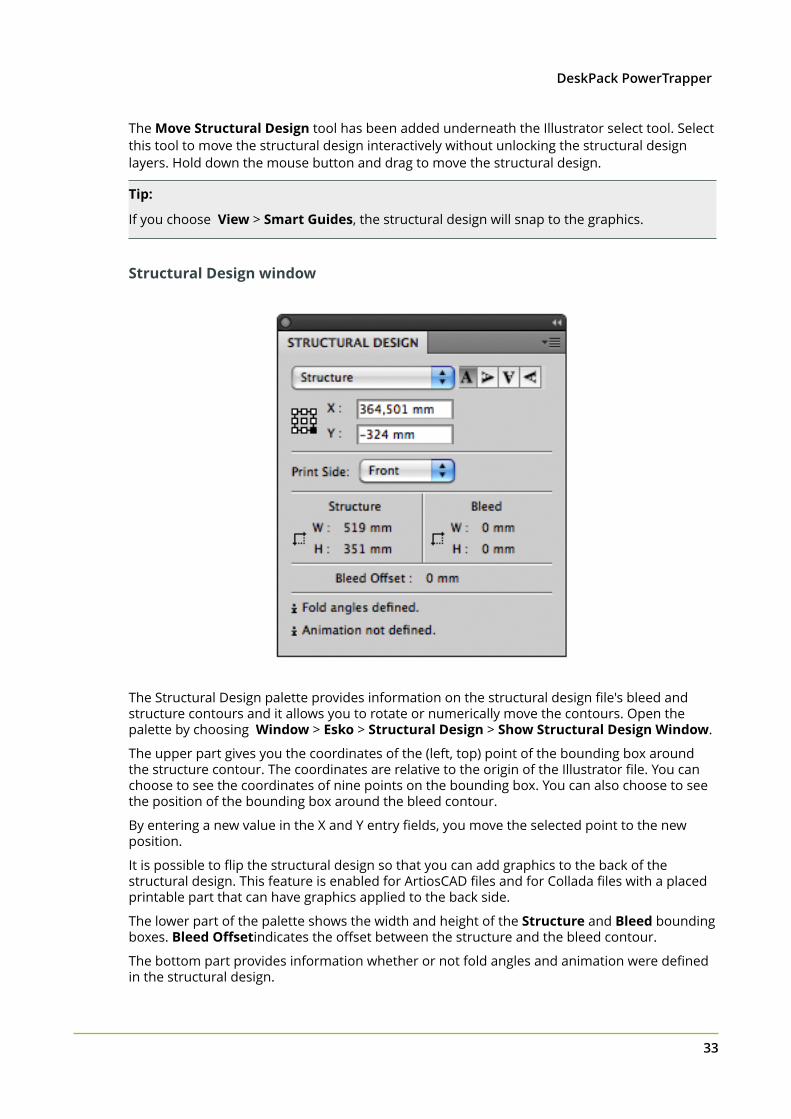
Structural Design window
The Structural Design palette provides information on the structural design file's bleed andstructure contours and it allows you to rotate or numerically move the contours. Open thepalette by choosing Window > Esko > Structural Design > Show Structural Design Window.
The upper part gives you the coordinates of the (left, top) point of the bounding box aroundthe structure contour. The coordinates are relative to the origin of the Illustrator file. You canchoose to see the coordinates of nine points on the bounding box. You can also choose to seethe position of the bounding box around the bleed contour.
By entering a new value in the X and Y entry fields, you move the selected point to the newposition.
It is possible to flip the structural design so that you can add graphics to the back of thestructural design. This feature is enabled for ArtiosCAD files and for Collada files with a placedprintable part that can have graphics applied to the back side.
The lower part of the palette shows the width and height of the Structure and Bleed boundingboxes. Bleed Offsetindicates the offset between the structure and the bleed contour.
The bottom part provides information whether or not fold angles and animation were definedin the structural design.

3 DeskPack PowerTrapper
34
Click one of the Rotation icons to rotate the structural design contours. Rotation alwayshappens around the center of the structure contour.
Create Varnish PlateChoose Window > Esko > Structural Design > Create Varnish Plate....
• If you choose Use Bleed Outline then the contour will be created from the bleedoutline minus the coating free areas (if any).
• If you choose Use Artboard, then the contour will be created from the Artboardminus the coating free areas.
• If you choose Use Bounding Box of Structure, then the contour will be createdfrom the Bounding Box of the structure minus the coating free areas.
When choosing Use Artboard or Use Bounding Box of Structure, you can specify apositive or negative offset. The resulting varnish plate will be enlarged or shrunk withthe specified offset in relation to the artboard or the bounding box.
This tool outputs a contour filled with a light-yellow spot color. This contour will be putin a new layer named ‘Varnish’. This layer will be inserted directly under the structuraldesign layers.
Note:
Create Varnish Plate will automatically exclude the coating free zones in the structuraldesign file, if any.

3DeskPack PowerTrapper
35
Expand Structural Design LayerChoose Window > Esko > Structural Design > Expand Structural Design Layer... .
Select the structural design layer that you want to expand into a new Illustrator layer.All art on the structural design layer will be copied to the new Illustrator layer. The arton the new layer is no longer tagged as structural design objects. The resulting objectsare in the technical structural design inks.
One common use where you would use this tool is when you are interested in creatinga clipping path from the bleed outline of the structural design file.
Structural Design PreferencesIf you open or place structural design files created by older versions of e.g. ArtiosCAD ( < 7.3),the structural design layer names might be visualized incorrectly. In the picture below, the ßand u in bemaßung are not visualized correctly.

3 DeskPack PowerTrapper
36
This happens when the layer name that was saved in the structural design file used a differenttext encoding than the one that is used to visualize the layer name in Illustrator. As structuraldesign files created by older versions of e.g. ArtiosCAD ( < 7.3) do not contain the used textencoding, the plug-in can only guess which text encoding was used. It will by default take thecurrent language settings.
This should yield the correct result, unless you are for example trying to open a Germanstructural design file on a Chinese system. If this is the case, you can overrule the text encodingin Illustrator > Preferences > Esko > Structural Design Preferences…on MAC or File >Preferences > Esko > Structural Design Preferences… on PC.
From ArtiosCAD file: ARD files written from ArtiosCAD 7.3 onwards will contain the textencoding used for layer names. So for those files, the layer browser in Illustrator will alwaysvisualize the structural design layer names correctly, even if you are for example opening aGerman text-encoded ARD file on a Chinese system. For ARD files written by older versions ofArtiosCAD, the plug-in will use your current language settings for text encoding. In most casesit makes sense to click this option.

3DeskPack PowerTrapper
37
Current language settings: If this option is selected, the plug-in will always use the textencoding of your system instead of the encoding that might be specified in the structuraldesign file.
Other: You can specify directly which text encoding should be used. In the example of aGerman ARD file that is opened on a Chinese system, you should switch the text encoding toWestern European (Windows Latin 1). If you click OK, the layer palette will be refreshed usingthe new text encoding. For the example above, the layer palette shows:
3.4.3 Structural Design Export
Structural Design Save asThe Structural Design Save as... saves a copy of the linked Structural Design file which is placedin the Illustrator file to a new location, The Illustrator file will link to the newly saved StructuralDesign file. Choose File > Structural Design > Save as...

3 DeskPack PowerTrapper
38
Export Selected Objects to ArtiosCAD FileArtiosCAD Export adds the item Export Selected Objects to ArtiosCAD File to the StructuralDesign menu. Only ARD files can be included when exporting to a new ArtiosCAD file.

3DeskPack PowerTrapper
39
Select the contours to export to the ARD file and choose File > Structural Design > ExportSelected Objects to ArtiosCAD File.
The Export Selected Objects to ArtiosCAD File dialog opens.

3 DeskPack PowerTrapper
40
Save selected objects inYou can choose to save the selected objects in the Main Design Layer or in Annotation Layers.If you save them in Annotation Layers, an ARD file will be created with annotation layers withthe same name as the illustrator layers.
Next to this, you can choose Layers based on ArtiosCAD Line Type swatches. If the selectedobjects are stroked with a swatch color with an ArtiosCAD line type name (e.g. cut, crease,bleed), then this option will create layers depending on the stroke color name:
• Cut and crease lines will go to a Main Layer
• Outside Bleed lines will go to an Outside Bleed Layer
• Outside Coating lines will go to an Outside Coating Layer
• Dimensions and text will go to a Dimension Layer
• All other linetypes will go to an Annotation Layer
For convenience, a swatch library ArtiosCAD Line Types is included with the plug-in. You candisplay the swatch library by selecting Window > Swatch Libraries > ArtiosCAD Line Types.In this swatch library, all ArtiosCAD design line types have been predefined.
Include a copy of ****.ARDYou can choose to include a copy of the ARD file that was loaded in the Illustrator document.The resulting ARD file will contain the selected objects AND what is in the CAD layers inIllustrator.
Remove linesIt is possible to remove some lines of the original ArtiosCAD file. This is meant to modify cutoutwindows. Do not attempt to remove fold lines with this tool. If you do this, the original foldangles will be lost.

3DeskPack PowerTrapper
41
Place this ArtiosCAD file in the documentIf you switch this option on, the resulting ARD file will be placed in the Illustrator document. Itwill replace the structural design file that was loaded originally.
PreviewIn the preview window, you see a preview of what will be saved. You can highlight the selectedcontours by toggling on Highlight Selection. You then see the distinction between the contoursthat are newly added to the resulting ARD file and those contours that come from the originalARD file.
If you click Save As, the Save As dialog opens.
If you have an ArtiosCAD file loaded in your Illustrator document, the software suggests as filename the name of the loaded ArtiosCAD file followed by _copy.
We recommend you not to overwrite the original ARD file as some functionality of the ARD filewill be lost: graphics layers are not copied and it will not be possible to rebuild the created ARDfile and text will be contourized.
Note:
Placed EPS objects and/or pixel-based objects cannot be copied to an ARD file. The fill color ofthe selected contours is not maintained in ArtiosCAD. Rather, the stroke color of the contourdetermines the line type in ArtiosCAD. If the selected contour is in the Main Design layer, thepointage of the contour will be 2. In all other cases, the pointage will be 0.

3 DeskPack PowerTrapper
42
ArtiosCAD - Copy to Clipboard
Note:
This function is only available on PC.
It can be found on the Edit menu:
ArtiosCAD - Copy to Clipboard copies the selected contours to the Windows Clipboard. Theycan directly be pasted into ArtiosCAD. If you have the same ArtiosCAD workspace open inArtiosCAD and have not modified it since opening it in Illustrator, when you paste the contentsof the clipboard into ArtiosCAD, they use the same placement as was used in Illustrator. Thisfunction is useful for ArtiosCAD users who need shapes from the graphics to be added to thebox design.
Copy to Clipboard also offers you the possibility to add the ARD file that is currently loaded inthe Illustrator document. Keep in mind that graphics layers are not copied. The resulting ARDfile is also not rebuildable and text will be contourized.

3DeskPack PowerTrapper
43
Note:
Placed EPS objects and/or pixel-based objects cannot be copied to an ARD file. The fill colorof the selected contours is not maintained in ArtiosCAD. The stroke color of the contourdetermines the line type in ArtiosCAD. If the selected contour is in the Main Design layer, thepointage of the contour will be 2. In all other cases, the pointage will be 0.
Relationship between stroke color in Illustrator and line type in ArtiosCADIf the contours are stroked with a swatch color with an ArtiosCAD line type name (e.g. cut,crease), then the corresponding items in ArtiosCAD will have the corresponding line type. Forexample, if you give your contour a stroke color with as name 'Annotation', the contour willbe in line type 'Annotation' in ArtiosCAD. If the name is not an ArtiosCAD line type name, thecontour will be a cut line. For convenience, a swatch library ArtiosCAD Line Types is includedwith the plug-in. You can display the swatch library by selecting Window > Swatch Libraries> ArtiosCAD Line Types . In this swatch library, all ArtiosCAD design line types have beenpredefined.
How to add a cutout window to an existing ArtiosCAD file?
1. Open or place an ARD file.
If you also have Studio Designer, you will see a 3D view of your folded box in the Studiowindow.
2. Create and select the cutout shape that you want to add to the ArtiosCAD file.

3 DeskPack PowerTrapper
44
3. Choose File > Structural Design > Export Selected Objects to ArtiosCAD File.
The Export Selected Objects to ArtiosCAD File appears.

3DeskPack PowerTrapper
45
4. Do one or more of the following:
• Save the selected objects in the Main Design Layer.• Include a copy of the original ARD file.• Place this ArtiosCAD file in the document.
For more information on the different options, please refer to Export Selected Objects toArtiosCAD File on page 38.
5. Click Save As....
The selected objects are saved in the Main Design Layer. They get the cut line type (whichis the default if you did not specify a swatch with as name an ArtiosCAD line type). Apartfrom the selected objects, the original ARD file is copied in the resulting ARD file and theresulting ARD file is immediately placed in the Illustrator document. If you have StudioDesigner, you will automatically see the ARD file with the cutout folded in 3D:

3 DeskPack PowerTrapper
46
How to modify a cutout window in an ArtiosCAD file?
1. Open or Place an ARD file that already contains a cut-out window.
If you also have Studio Designer, you will see a 3D view of your folded box in the Studiowindow.

3DeskPack PowerTrapper
47
2. Create and select the new cutout shape that you want to add to the ARD file.
3. Choose File > Structural Design > Export Selected Objects to ArtiosCAD File .
The Export Selected Objects to ArtiosCAD File appears.

3 DeskPack PowerTrapper
48
In the preview window you notice that you do not get the desired result. We need to removethe original cutout window.
4. Click Remove Lines.
The Remove Lines dialog appears.

3DeskPack PowerTrapper
49
5. In this dialog, you can select the lines you would like to remove. It will not be possible to
select the new lines. You can choose to hide the new lines by enabling Hide New Lines.6. Click and drag a rectangle around the original cutout window.
This window will be grayed out. This means that it will be removed in the final ARD file.

3 DeskPack PowerTrapper
50
7. Click OK.
This bring you back to the Export Selected Objects to ArtiosCAD File dialog. In thepreview window you notice that the original cutout has been removed.

3DeskPack PowerTrapper
51
8. Click Save As.9. Specify a file name in the Save As dialog.
The software suggests the name of the loaded ArtiosCAD file followed by _copy.10.Click Save.
If you have Studio Designer, you will automatically see the ARD file with the new cutoutfolded in 3D.

3 DeskPack PowerTrapper
52
3.5 The Page Box Plug-in
3.5.1 Introduction
Page Boxes are used to define the outside borders and margins of your document, and it isused in the Esko Software Suite workflow environment.
Page Box definitions are saved as part of the Illustrator file used by the plug-ins Shuttle andPowerLayout Client.
Page Boxes are not taken into account when printing directly from Adobe Illustrator, nor arethey exported when exporting to a non-native format via standard Adobe plug-ins. They do notappear as objects in the Layers palette.
You can find the Page Box plug-in in Window > Esko > Trim Box and Media Box
The Page Box plugin can work in two modes:
• Trim Box and Media Box (defining only those two page boxes). See Trim Box and Media Boxon page 52
• All Page Boxes. See All Page Boxes on page 56
You can switch mode by selecting Switch to [mode] from the flyout menu.
3.5.2 Trim Box and Media Box
1. Trim Box Size: Select the size from the dropdown list.2. Trim Box Width/Length: Enter the Width/Length if you want a custom size.

3DeskPack PowerTrapper
53
Tip:
The units are defined in the Illustrator preferences.
3. Trim Box Orientation: Select the orientation: portrait/landscape.
Note:
When the Trim Box is being dragged or Width or Height editboxes edited, the radio buttonsPortrait/Landscape flip automatically so that Landscape is active whenever Width > Heightand Portrait whenever Width < Height.
4. Fit Trim Box to
• Fit Trim Box to Artboard
• Fit Trim Box to Artwork
• Fit Trim Box to Selection
• Fit Trim Box to CAD
5. Media Box (Margins) enter the top, bottom, left and right values.
Tip:
The units are defined in the Illustrator preferences.
6. Fit Media Box to
• Fit Media Box to Artboard
• Fit Media Box to Artwork
• Fit Media Box to Selection
• Fit Media Box to Bleed / CAD (when no bleed was defined the cad will be taken as
reference)7. Fit Artboard to
• Fit Artboard to Trim Box• Fit Artboard to Media Box
8. Show Trim Box and Media Box: To display or hide the trim Box and Media Box, use thistoggle.
9. See more page boxes: In case page boxes other than Trim and Media box are defined, thislink will open the All Page Boxes version of the palette. See All Page Boxes on page 56
10.Trim Box and Media Box dropdown menu
• Switch to All Page Boxes. see All Page Boxes on page 56
• Fit Trim Box to Artboard

3 DeskPack PowerTrapper
54
• Fit Trim Box to Artwork• Fit Trim Box to Selection• Fit Trim Box to CAD• Fit Trim Box to Crop Area• Fit Media Box to ArtBoard• Fit Media Box to Artwork• Fit Media Box to Selection• Fit Media Box to Bleed / CAD (when no bleed was defined the CAD will be taken as
reference)• Fit Media Box to AI Bleed Box• Fit Artboard to Trim Box• Fit Artboard to Media Box• Use Transform bounds: if this option is enabled, TrimBox/MediaBox will respect as
they are defined in Adobe Illustrator. If disabled, TrimBox/MediaBox will respect visiblebounds.
• Move Trim Box and Media Box ... open the 'Move Trim Box and Media Box' interface• Delete Trim Box and Media Box
The figure below illustrates the Trim Box (borders) and Media Box (margins) of an outputdocument as interpreted on an Esko system. The full black line represents the borders(corresponding to one of the above options) while the dotted black line indicates the marginsof the document:
Moving and Scaling Trim Box and Media BoxTo move or change the size of the Trim and Media Boxes, you can either
• Select the Trim and Media Box Tool from the AI tool palette.
Use the Trim and Media Box to click and drag the Trim and Media Box.
• Select the Trim and Media Box Tool from the AI tool palette.

3DeskPack PowerTrapper
55
• ALT +drag = scale from the center out
• SHIFT + drag = constrained scaling
• ALT + SHIFT + drag = constrained scaling from the center out
OR
• Select a preset from the drop down menu. OR
• Use the numeric input field. The numeric input field appears when you select Move TrimBox and Media Box in the dropdown menu.
Tip:
Double-clicking Trim and Media Box tool in toolpalette opens the 'Move Trim Box and MediaBox' dialog.
OR
• You could use one of the “fit to” options (to Artboard, artwork, selection, cad or crop area).

3 DeskPack PowerTrapper
56
Tip:
The units are defined in the Illustrator preferences.
3.5.3 All Page Boxes
Using the All Page Boxes mode, you can set all 5 page boxes: Media Box, Crop Box, Bleed Box,Trim Box and Art Box
1. Media box: this is the page format2. Crop box: includes the Bleed box and all marks.3. Bleed box: defines the trimmed page plus the bleed.4. Trim box: this is the net document format.5. Art box: the Art box can be used to specify any section of the page.
You can see the dimensions of all Page Boxes in the Page Box list. You can
1. Select a Page Box in the list. Its details will be shown in the bottom part of the dialog.2. Enable (or disable) the specific page box by enabling the Set [...] Box option.3. Enter the offset, width and heigth. You can click the button to swap width and height. In the
Size dropdown, you can select any of the preset sizes.4. Click one of the Fit to buttons to fit the selected page box respectively to the ArtBoard,
Artwork, Selection or CAD.5. Use the Show All Page Boxes to show or hide all Page Boxes in your job.

3DeskPack PowerTrapper
57
3.6 The Inspection Setup Plug-InThe Inspection Setup Plug-In allows you to define Inspection points or Inspection boxes in yourjob.
For each of these Inspection points, you will see the Lab value and DeltaE. For every Inspectionbox, you can set the Profile. Inspection points and boxes will be exported, e.g. to be used in anInspection System in inline presses. This Inspection System will warn if the values measured ata specific position are more different from the entered Lab values than the allowed deltaE, or ifthe Inspection box or Dynamic Art box doesn't match the defined profile.
The plug-in consists of
•the Inspection Setup tool , under the Eyedropper tool in the toolbar
• the Inspection Setup palette, which can be opened by selecting the Inspection Setup tool,or by adding an Inspection point.

3 DeskPack PowerTrapper
58
3.6.1 Adding and changing Inspection points
The Inspection Setup palette shows all the Inspection points, indicating the coordinates(distance from the top left corner of the trim box), Lab value and default deltaE value.
•Select the Inspection Setup tool from the Illustrator toolbar and click in the job toinsert a new Inspection point.
The Inspection point will be visible in the job, with its number next to it.• Select an Inspection point in the palette to highlight the corresponding Inspection point on
the Illustrator job. You can select multiple Inspection points•
Select one or more Inspection points and click the delete button to delete theInspection points
• You can manually change the Lab and deltaE value for every Inspection Point.•
Click the Refresh button to update the Inspection Point list.

3DeskPack PowerTrapper
59
• You can move an Inspection point in two ways:
• Click within the Inspection point, and drag it to the new location• In the Inspection Point list, change the coordinates for the Inspection point.
3.6.2 Adding and changing Inspection boxes
The Inspection Setup palette shows all the Inspection boxes.
•Select the Inspection Setup tool from the Illustrator toolbar and click and drag inthe job to insert a new Inspection box.
The Inspection box will be visible in the job, with its number next to it. When creating a newInspection box, the Default Profile is used
• Select an Inspection box in the palette to highlight the corresponding Inspection box on theIllustrator job. You can select multiple Inspection boxes.
•Select one or more Inspection boxes and click the delete button to delete theInspection boxes
• You can manually change the Profile.• You can move or change an Inspection box in different ways:
• Click on the center point of the Inspection box, and drag it to move the Inspection box toa new location
• Click one of the 8 handles on the Inspection box, and drag to modify the Inspection box
3.6.3 Dynamic Art Placeholders
The Dynamic Art section of the Inspection Setup palette shows all Dynamic Art placeholdersdefined in the job.
• Enable the checkbox in front of a Dynamic Art placeholder to use it as an Inspection box.
When adding a Dynamic Art placeholder, the Default Profile is used• Select a Dynamic Art placeholder in the list to highlight the corresponding Dynamic Art
placeholder on the Illustrator job. You can select multiple Dynamic Art placeholders• You can manually change the Profile.• Disable the checkbox in front of a Dynamic Art placeholder to stop using it as an Inspection
box.
3.6.4 Import and Export
When exporting normalized PDF, Inspection points and boxes added to a job are saved in thePDF file, and these Inspection points and boxes will be recognized by Packadge and AE.
Also, when opening a normalized PDF from another Esko product (such as PackEdge), theInspection points and boxes information stored in the PDF document will be shown in theInspection Setup palette.

3 DeskPack PowerTrapper
60
Note: Dynamic Art placeholders are not saved as such in normalized PDF. The selectedDynamic Art placeholders will be exported as "Inspection Box". If you import the normalizedPDF in Adobe Illustrator again, or open the normalized PDF file in e.g. Packedge, these DynamicArt placeholders will be shown as Inspection Boxes
3.7 MessagesThe Messages plug-in is included with all Esko DeskPack plug-ins.
It displays the information, warnings and errors from all the other DeskPack plug-ins, and tellsyou which plug-in generated them.
You can filter the messages you see when the Messages palette is open, and clear or save allmessages if you need to.
3.7.1 The Messages Palette
The Messages palette pops up automatically when another DeskPack plug-in generates awarning or an error.
You can also open it from Window > Esko > Messages.
This palette shows you:
•the message’s severity ( information, warning or error),
• the message’s text in the Message column,
• which Plugin generated the message,
• the Time the message was generated at.
Tip: You can click the column headers to sort the messages, and drag the columns horizontallyto adjust their widths.
You can also use the palette to get extra information and / or select the objects that generatedwarnings or errors:
• click a message to display extra information at the bottom of the palette.

3DeskPack PowerTrapper
61
• click the triangle in front of a message to see the list of objects it relates to.
• click one of the objects in the list to select it in the file.• double-click that object to select it and zoom in on it in the file.• double-click the message to select and zoom in on all objects it relates to in the file.
3.7.2 Filtering the Messages
You can show or hide certain types of messages using the palette’s fly-out menu.
• To hide:
• all informational messages, select Hide Info Messages in the fly-out menu,• all warnings, select Hide Warning Messages,• all errors, select Hide Error Messages.
• To show them again, select either:
• Show Info Messages,• Show Warning Messages,• Show Error Messages.

3 DeskPack PowerTrapper
62
• To only show the last message, select Show Last in the fly-out menu.• To show all messages again, select Show All.
When showing all messages, you can see Show: All at the bottom right of the palette.
When filtering messages (for example filtering out the warning messages, or showing only thelast message), you can see Show: Filtered at the bottom right of the palette.
3.7.3 Saving the Messages
To save all messages in a text file:
1. Select Save Messages as... in the fly-out menu.

3DeskPack PowerTrapper
63
2. In the browser window that opens, choose the name and location to use for saving your file.
3.7.4 Clearing the Messages
• To remove all messages from the Messages palette, select Clear in the fly-out menu.
3.8 Esko Document SetupBy choosing File > Esko Document Setup you can open the Esko Document Setup dialog.
The settings made here are saved in the Esko XMP Document Information.
3.8.1 Distortion
The vertical and horizontal distortion value is saved with the document and used by Esko RIPswhen generating the final output. It allows to compensate for distortions in certain printingmethods, e.g. flexography. On mounting a flexo plate on the press, it is stretched out in onedirection. By making the output slightly smaller than needed (e.g. 95%), we compensate for thisdistortion.
Values for vertical and horizontal distortion is limited to 90% - 110%.
3.8.2 Screen Registration
The Screen Registration parameter allows to choose
•
if the RIP should reset the screening origin for every one-up
•
or keep the same screening origin for the complete document
Below a schematic representation of a Repetition with (left) and without (right) resetting thescreen origin for every one-up.
3 DeskPack PowerTrapper
64
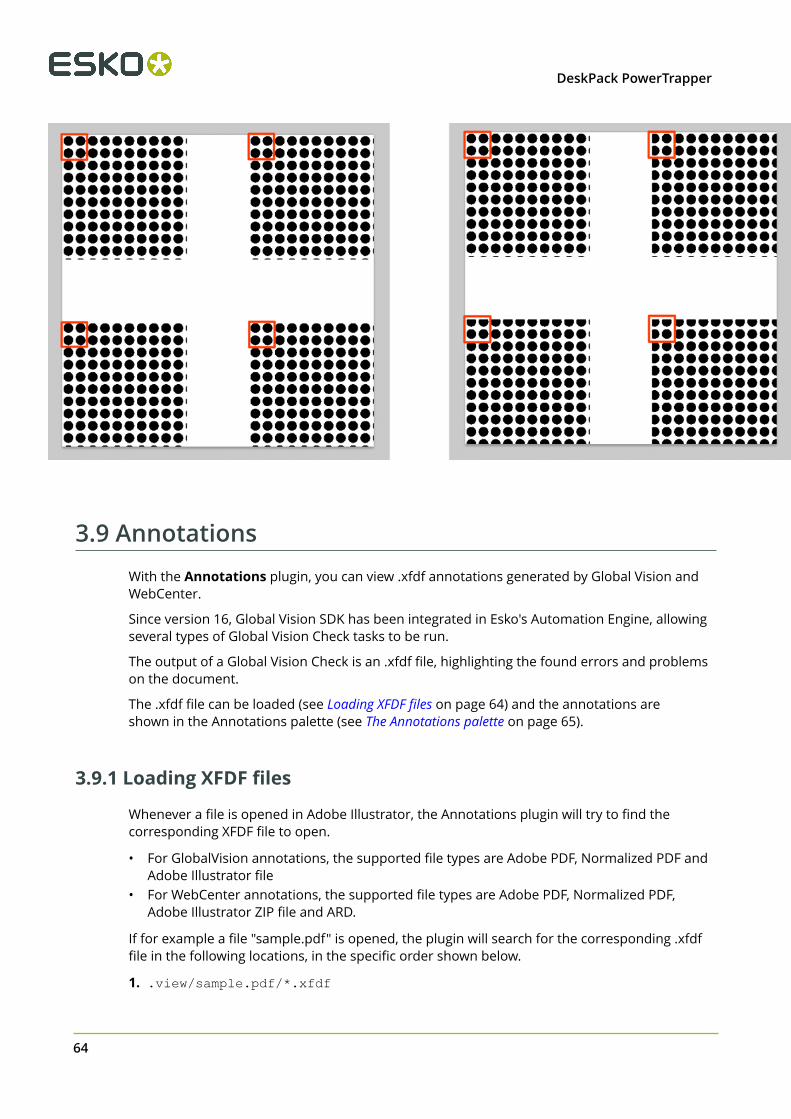
3.9 AnnotationsWith the Annotations plugin, you can view .xfdf annotations generated by Global Vision andWebCenter.
Since version 16, Global Vision SDK has been integrated in Esko's Automation Engine, allowingseveral types of Global Vision Check tasks to be run.
The output of a Global Vision Check is an .xfdf file, highlighting the found errors and problemson the document.
The .xfdf file can be loaded (see Loading XFDF files on page 64) and the annotations areshown in the Annotations palette (see The Annotations palette on page 65).
3.9.1 Loading XFDF files
Whenever a file is opened in Adobe Illustrator, the Annotations plugin will try to find thecorresponding XFDF file to open.
• For GlobalVision annotations, the supported file types are Adobe PDF, Normalized PDF andAdobe Illustrator file
• For WebCenter annotations, the supported file types are Adobe PDF, Normalized PDF,Adobe Illustrator ZIP file and ARD.
If for example a file "sample.pdf" is opened, the plugin will search for the corresponding .xfdffile in the following locations, in the specific order shown below.
1. .view/sample.pdf/*.xfdf

3DeskPack PowerTrapper
65
2. .view/sample*.xfdf
3. sample*.xfdf
4. ./sample_wcr.xfdf for WebCenter annotations
3.9.2 The Annotations palette
The Annotation palette will show all Annotations found in the .xfdf file. You can open thepalette by choosing Window > Esko > Annotations.
There are different types of annotations: Barcode, Braille, Spell Check, Artwork, Text Compareand WebCenter annotations.. You can browse to them by clicking the buttons on top of thepalette.
Note: If the document only contains WebCenter annotations, you will not have any filteringoptions. If your document only contains Global Vision annotations, the "WebCenter" buttonwill be hidden.

3 DeskPack PowerTrapper
66
For every issue found, an entry in the list is shown. Some of these annotations have textcontent, while others can have an image preview, showing the difference between the actualartwork and how it should look.
If Show only selected annotations is enabled, only the annotations you select in the list willbe highlighted in your job using a colored rectangle. Otherwise, all annotations in the job willbe highlighted.
If Zoom is enabled, selecting an annotation in the list will automatically zoom in on the issue.
3.9.3 Multipage PDF files with Annotations
An XFDF file can contain annotations for a multipage PDF. Every annotation will have areference to what page it belongs to.
If you import a multipage Normalized PDF, the plugin knows what page you imported, and onlythe Annotations for that specific page will be shown.
If you import a multipage PDF as Adobe PDF, the plugin can't know what page you imported. Inthat case, the Annotation palette will have a dropdown at the bottom of the palette, to decidefor what page you want to load the annotations.
Note: Multi-page annotations is not supported for WebCenter annotations
3.9.4 Updating
Each annotation contains a time stamp of creation. In case the source file is modified andsaved later than the annotation, a warning icon will be shown on top of the palette, indicatingthe annotations might be out of sync with the document.
If the document is opened from WebCenter, you can choose Update Annotations from theflyout menu in the Annotations palette, to get the latest annotations from WebCenter. Incase the annotations can not be loaded (e.g. you are no longer logged in with WebCenterConnector, there are no annotations available for the document, or the document no longerexists) you will get a warning message indicating why loading didn't work.

4DeskPack PowerTrapper
67
4. PowerTrapper for Adobe Illustrator
4.1 Introduction to PowerTrapper Standalone
4.1.1 What is Trapping?
The trapping process is a safeguard against possible (even likely) fluctuations in the printingprocess.
Minor discrepancies in registration, slight paper shifting or stretching of e.g. PE foil can causeinks to misregister. When two adjoining colored objects do not meet exactly, you can end upwith a printed result like the one below:
The overlap creates a dark area and the gaps cause an undesirable light area. To prevent thesepotential discrepancies, a trap can be added, causing the original colors to slightly overlap eachother:
In general trapping is necessary when:
• The two colors each consist of at least one ink but they have no common inks.
• The two colors have one or more common inks, but the percentages of those common inksare significantly different in the two colors (for example a color made of 50% M and 10% Cwill be trapped with a color made of 50% Y and 80% C).

4 DeskPack PowerTrapper
68
Placing a fine line where the colors join, made of a color that contains components of bothadjoining colors, can trap such areas effectively.
4.1.2 What is PowerTrapper Standalone?
The PowerTrapper Standalone plug-in allows you to define trapping settings to automaticallytrap your documents in Illustrator.
You can:
• define common and advanced trapping settings (see The Trap Dialog on page 70),
• create specific trapping rules for trapping pairs of your choice (see Rules on page 79),
• save all your trapping settings as a preset to be able to reuse them on other documents(see Trap Presets on page 83),
• select your traps for further editing (see The Trap Select Tool on page 84),
• have a visual overview of the trapping settings by color pair, and refine them if necessary(see The Color Pairs Palette on page 85),
• remove your traps at any time as PowerTrapper Standalone trapping is non-destructive(your traps are created in a separate Trap Layer, see The Trap Layer on page 84).
Note:
• We recommend you use Illustrator’s Overprint Preview mode to see your traps moreaccurately.
• PowerTrapper Standalone doesn’t trap hidden objects. If you want to exclude an objectfrom trapping, you can either hide it or use a rule.
4.2 Trapping with PowerTrapper StandaloneTo introduce you to PowerTrapper , here is how to add simple traps to a document.
1. Open the document you want to trap.2. Go to Window > Esko > PowerTrapper > Trap ... or use the Option + Shift + Command + X
shortcut (on Mac).3. In the Trap dialog that opens, enter the Trapping Distance you want to use.

4DeskPack PowerTrapper
69
4. Go to the Color & Shape tab and choose:
• how to Truncate Traps (on center or on edge),• how to shape the End Caps (square, round or object dependent),• how to shape the Trap Corners (round, beveled or mitered).

4 DeskPack PowerTrapper
70
Note:
For more information about the different trapping settings you can choose, see:
• Distance and Direction Settings on page 71,
• Color and Shape Settings on page 75,
• Processing Settings on page 78.
5. Click the Trap button to trap your document. This creates your traps in a new Trap Layer.
Note:
• To cancel the trapping process, use the Escape key.
• To undo your traps once trapping is done, use Command + Z.
4.2.1 The Trap Dialog
The Trap dialog is where you define all your trapping settings.
1. Go to Window > Esko > Trapping > Trap ... , use the Option + Shift + Command + Xshortcut (on Mac) or double-click the Trap Select tool to open the Trap dialog.
2. Choose your trapping settings in the Distance & Direction, Color & Shape, and Processing
tabs.3. If needed, define trapping rules.4. Save your trapping settings as a trap preset to be able to reuse them on another document.

4DeskPack PowerTrapper
71
Note: The Trap Preset List contains 6 default presets.
Distance and Direction SettingsTrapping
You can choose between two trapping modes:
• Normal Trapping: This selects adjoining color pairs, which are likely to cause registrationproblems like ugly light gaps, and unwanted halo effects.
PowerTrapper Standalone automatically chooses the most appropriate trap direction basedon the relative luminance of the adjoining colors. Lighter colors are generally trapped intodarker colors to minimize the visual effect of the trap.
• Reverse Trapping: This prevents overprint of adjoining color areas by trapping these colorpairs with a white knockout (erasing) trap. The white knockout trap is put on top of thelighter of the two colors.
This is useful to prepare a job for Dry Offset printing (e.g. metal beverage cans) whereoverprinting of inks is not allowed as the inks would contaminate each other on the blanket.
Trapping Distance
Enter the width you want to give your traps. The unit used is the General unit defined inIllustrator’s Unit & Display Performance Preferences.
The default trap width is 0.2 mm (or equivalent in your chosen unit).
Minimum Ink Difference
Trapping is applied to two adjoining colors when either:
• The two colors each consist of at least one ink but they have no common inks.• The two colors have common inks but there is a difference of at least the Minimum Ink
Difference percentage for two or more inks making up these colors.
These differences in ink percentages must be in opposite directions.
For example, with the default minimum ink difference percentage of 10%, the following twocolors will be trapped:
1st color: C 5% M 10% Y 50% K 15% (+10% K)
2nd color: C 5% M 10% Y 85% K 5% (+35% Y)
Increase the minimum ink difference to trap colors that are more different, lower it to trapcolors that are more similar.
Image Trapping
• Automatic (default): this determines the most suitable trap direction automatically, bycomparing the average lightness of the CT image with the lightness of the adjoining area,then traps the lighter color into the darker one.
• Always Towards Images: this always traps line art under adjoining CT images.
• Always Towards Line Art: this always traps CT images under adjoining line art.
Pull Back
An ink pull back keeps away all but the darkest ink of a color area composed of multiple inksthat borders to a very light background.

4 DeskPack PowerTrapper
72
It prevents individual inks from the composed color to become visible on the background dueto registration errors during the printing process.
Ink pull back is also known as “Cutbacks” or “Keepaways”.
The example below shows an object with 100% dark blue and 50% magenta on an emptybackground. 50% magenta is pulled back and a fine line of 100% dark blue remains. The colorthat remains (dark blue) is the pull back ink.
• Automatic (default): this creates pull backs on rich black or rich colors, when the color leftin the pull back area is not very different from the composed color.
In the example below, the left color is composed of 100% purple ink and 20% cyan. Thedarkest ink (purple) is not very different from the composed color, so using the Automaticpull back option will create a pull back.
The right color is composed of 100% dark red ink and 20% blue ink. The darkest ink (darkred) is very different from the composed color, so using the Automatic pull back option willnot create a pull back.
• Only Pull Back Rich Black: this only creates pull backs on rich black.
• Do Not Pull Back: this never creates any pull back.

4DeskPack PowerTrapper
73
Advanced SettingsClick the triangle beside Advanced Settings to show the advanced settings.
Trapping Distance
If you want to use a different distance when trapping into black, spot colors or images or whencreating pull backs, enable the corresponding option and enter the trapping distance to use.
The unit used is the General unit defined in Illustrator’s Unit & Display PerformancePreferences.
Image Trapping
If you don’t want images to be trapped with each other, disable Trap images to images.
Pull Back
If you chose to use Automatic pull back (see Pull Back), the Also pull back light inks option isavailable. Enable it if you want to create pull backs even when the pullback ink (ink remainingin the pull back area) is visibly different from the composed color.
Enable Pull back images and gradients if you want to create pull backs on images andgradients.
Trap decision
• By default, PowerTrapper uses the color luminance (Use Lightness) to define the trappingdirection, except for opaque inks, for which the Inks order is used.
• trap direction: from brightest to darkest• If the Treat spot colors as opaque option is chosen, color luminance is used only for CMYK.
For opaque and spot inks, the trap direction is determined by the ink sequence.
• trap direction for spot colors only: towards the separation listed the lowest in theSeparations palette darkest
• trap direction goes from the process to the spot color if the spot color is below theprocess color in the Separations list
• trap direction if the spot color is above the process color: from brightest to darkest• By selecting Use separation order, the trap direction is determined by the ink sequence for
all inks, including CMYK.
• trap direction: towards the separation listed the lowest in the Separations palette darkest• Use reverse separation order does the same, using the reversed ink sequence.
• trap direction: towards the separation listed the highest in the Separations palettedarkest
Note: Using the Separation Order option will give the same result as changing all inks(including CMYK) to Opaque.
Overshoot Mode
You can choose between the following three overshoot modes:
• Automatic (default): The centerline behavior is according the rules determined in the colorpair list.
• Never on Dark Areas: The centerline is forced not to get beyond the center of dark areas.• Never: The centerline is forced not to get beyond the center of any area.
An example:

4 DeskPack PowerTrapper
74
During trapping, this example will generate the following color pairs:
By default (Automatic), this color pair list results in the following traps:
If the parameter is set to Never on Dark Areas, this will result into:
If the parameter is set to Never, this will result into:

4DeskPack PowerTrapper
75
Color and Shape SettingsTrap Color Intensity
By default, PowerTrapper uses the full color of the object to spread in the trap (100% trap colorintensity).
However, you can create a trap of a lighter color by reducing the trap color intensitypercentage.
Image Trap Color
Choose how to trap your images:
1. Use Original Image Data (default): when spreading an image, PowerTrapper uses theunderlying image data (when the image is clipped) to create the trap (see example 1 below).
Note: When there is no underlying image data (the image isn’t clipped), it will create anempty trap.
2. Extend Image Data: PowerTrapper will automatically extrapolate the image along itsclipping path edge to ensure the trap looks as expected even if there is no clipped imagedata outside the visible image (see example 2 below).
3. Use an Approximate Flat Color: Instead of using existing or extrapolated image data inthe trap, PowerTrapper will use a solid color. A suitable color is determined by averaging theimage’s colors along its boundary with the object to trap (see example 3 below).
Note: If the Use Postscript Compatible Image Traps preference is on, the image trap coloroption has no influence on the result. Trapping will not generate any extra image data butimage traps will create traps with lineart representing vectorized pixels. The lineart will alsouse Postscript Overprints instead of the multiply blend mode. These image traps are alwayscreated using the 'Use Original Data' option. Note that to have a correct visualization of yourtraps, you need to switch on the 'Overprint Preview' in the Illustrator View menu.

4 DeskPack PowerTrapper
76
Note: Convert Blended Objects to Images in the PowerTrapper Preferences will convertblended objects to images before trapping.
Truncate Traps
PowerTrapper can truncate the trap so that it doesn’t stick out on another color. There are twotruncation modes:
•On Center (default): when a portion of a trap comes too close to the contour ofanother object, PowerTrapper Standalone limits it to half the distance between the trappedobject and the other object.
•On Edge : when a portion of a trap comes too close to the contour of another object, itis truncated on the other object’s edge.
End Caps
This option specifies how to shape the ends of an open trap.
•Square (default): this option ends the trap at right angle to the adjoining object.
•Round : this rounds the ends of the trap. This option is typically only used incombination with white knockout (reverse trapping).
Attention:
We recommend not to use Round End Caps together with Truncate Traps OnCenter, as this can generate some artefacts (the round caps will be truncated).
•Object Dependent : with this option, the trap is a logical continuation of the contour ofthe spread object.

4DeskPack PowerTrapper
77
Trap Corners
This option allows you to change how the traps’ sharp corners will be handled.
•Round (default): a round cap will be placed at all corners.
•Beveled : this will cut sharp corners off.
•Mitered : this option works with a miter ratio.
The miter ratio serves to limit the length of the sharp corner (the distance from the base ofthe trap to the corner point).
The default miter ratio value is 4. This means that if the length of the sharp corner is morethan 4 times the Trapping Distance, then the corner will be cut off (beveled). If it is lessthan 4 times the Trapping Distance, the corner will be left as it is.

4 DeskPack PowerTrapper
78
Advanced SettingsClick the triangle beside Advanced Settings to show the advanced settings.
Truncate Traps
If you want to truncate traps into black differently, select Into black and choose the truncationmode (On Center or On Edge). For more information about truncation modes, see TruncateTraps.
Processing SettingsColor Pairs
PowerTrapper can trap all hits (occurrences) of a color pair the same way, or recalculate thetrap direction for different hits.
• Each hit can have its own decision (default): this recalculates the trap direction for eachhit of a color pair.
• Same decision for all hits: this traps all hits of the same color pair in the same direction.
• Same decision for objects smaller than: this uses the same trap direction for hits of acolor pair belonging to small objects, and recalculates the trap direction for hits belongingto bigger objects.
Use the field next to the option to determine the maximum size of small objects.
The unit used is the General unit defined in Illustrator’s Unit & Display PerformancePreferences.
The default size is 1 mm (or equivalent in your chosen unit).
Restrictions
In some cases PowerTrapper can safely ignore certain object types to speed up the trapping.
• Respect existing traps: if your document has already been trapped, select this option tokeep the existing trap layer out of the trapping process.
• Ignore bitmaps : this keeps bitmap pixel data from being trapped. Bitmap data iscontourized before trapping, which may slow down trapping depending on the bitmap’scontents. Bitmaps with lots of small isolated islands will typically take a longer time to trap.
Attention: When you indicate an object type to ignore, it will be ignored completelyas if it did not exist in the job. Also, the ignored objects will not truncate trapping areasresulting from other objects below them.
If the Respect existing traps is enabled, traps in the selection will be kept, and no trapping isperformed on these locations. If the option is off, selected traps will be removed, and will bere-trapped. This only works for traps created by PowerTrapper or Instant Trapper.
Small Gaps
Some input jobs contain very small unintentional gaps between neighboring objects,preventing the correct trapping of these objects. Although it is better to clean up such jobsbefore trapping, PowerTrapper can ignore these gaps automatically.
To use this option, select Close when smaller than and enter the maximum size small gapscan have.

4DeskPack PowerTrapper
79
The unit used is the General unit defined in Illustrator’s Unit & Display PerformancePreferences.
The default size is 0.01 mm (or equivalent in your chosen unit).
Attention: If you set a big gap size, trapping may become slower, and small parts ofthe job may be ignored during trapping.
RulesRules allow you to define custom trapping settings for specific trapping pairs.
When to Use Rules?
In most cases the general trapping settings you enter in the Trap dialog will give you excellentresults, but in some cases you will need to refine them using rules.
Rules allow you to specify exceptions to the general trapping settings for certain color pairs.They are an advanced feature and should be used only by experienced users.
For example, you can use them in the cases below:
• To set a different trap distance for a specific spot ink.
Sometimes you need a larger trap distance for spot inks if there is no other ink to help coverleaks on the press.
• To prevent trapping or ink pull back in specific cases.
Depending on the type of the adjoining colors, trapping and / or pull back may beundesirable.
• To force a specific trap direction.
PowerTrapper determines the trap direction based on the relative lightness of the adjoiningcolors. If the colors have a similar lightness level, it selects an arbitrary direction. You canuse a rule to make it always use a particular direction for a color pair.
• To specify a different shape and / or truncation mode for certain color pairs.
For example you can choose to use “On Center” truncation when trapping under a 100%black line and “On Edge” truncation on all other color pairs.
Creating a Rule
1. Click the Add Rule button at the bottom of the Trap dialog.

4 DeskPack PowerTrapper
80
2. In the pop-up that opens, choose the trapping pair to apply the rule to using the From and
To lists.
You can create a rule to trap from/to:
• any color,
• a particular ink (process, spot or opaque),
Note:
In this case, you can choose the ink name, from which Minimum Density the rule willapply, and if the color must be pure (no other separation in the color object) to apply therule.
If Spot Ink is selected, the dropdown underneath will contain all Spot Colors used in thedocument.
• A specific Printing Method
• a particular object (image, gradient or empty background),
• the registration color.3. Choose the contents of the rule.

4DeskPack PowerTrapper
81
Options Description
Trap • Automatic lets PowerTrapper calculatethe trapping direction.
• Always Trap always spreads the “From”color/object on the “To” color/object.
• Do Not Trap never traps the “From” and“To” colors/objects together.
Trapping Distance Use this to define a special trappingdistance for the trapping pair.
Trap Color Intensity Use this to define a special trap colorintensity for the trapping pair.
Pull Back • Automatic lets PowerTrapper decideif there should be a pull back on thetrapping pair.
• Always Pull Back always creates apull back on the trapping pair. Thedarkest ink of the pair is the pullback ink(remaining ink in the pull back area).
• Do Not Pull Back never creates a pullback on the trapping pair.
Pull Back Distance Use this to define a special pull backdistance for the trapping pair.
Pull Back Fill Mode • Normal gives normal pull backs.
• Sharpen allows sharpening on pullbacks. This sharpening is used e.g. forwhite text on images, on CD's or DVD's.Sharpening is done by pulling back theimage, and adding 100% black in thetrapping area.
Reverse • Automatic lets PowerTrapper decide ifthe trapping pair should have a reversedtrap.
• Always Trap Reversed always generatesa reversed trap for the trapping pair.
• Do Not Trap Reversed never generatesa reversed trap for the trapping pair.

4 DeskPack PowerTrapper
82
Options Description
Truncate Traps Choose if traps generated for the trappingpair should be truncated on center or onedge. See Truncate Traps for details.
End Caps Choose how to shape the ends of opentraps for the trapping pair (square, round orobject dependent). See End Caps for details.
Trap Corners Choose how to shape the trapping pair’strap corners (round, beveled or mitered).See Trap Corners for details.
Direction Mode Select into both colors to use bidirectionaltrapping. In case of bidirectional trapping,the trap will go half the trapping distance ineach direction.
Horizontal / Vertical distortion Set the percentage of the trapping distanceto be used in vertical / horizontal direction.In the example underneath, the trap wasgenerated with no vertical distortion (so100%, i.e. using the entered trap distance)and horizontal distortion set to 50% (i.e.half the trap distance).
4.If necessary, use the button to add contents to your rule.

4DeskPack PowerTrapper
83
You can use the button to remove contents.5. When you are done defining your rule, click OK.
You can now see your rule at the bottom of the Trap dialog.
When trapping your document, PowerTrapper will trap the trapping pairs that match rulesaccording to those rules, and the rest of your document according to the main trappingsettings.
If necessary, you can add another rule, or remove a rule previously created. You can also edit arule by double-clicking it in the Trap dialog.
Trap PresetsWith PowerTrapper, you can save all your trapping settings as a preset to be able to reusethem on other documents.
Trap Presets can be shared between different Esko Applications (PackEdge, ArtPro,DeskPack, ...)
The Trap Presets list contains 6 default Presets that can't be changed or removed:
• Default• Bi-directional (including a rule to trap into both colors)• Combipress (including a rule based on Printing Method)• Offset (optimized for offset printing)• Reverse• Sharpening (including a rule optimized for sharpening)
Defining a Trap Preset
1. Define your trapping settings in the Trap dialog. Add rules if you need to.
See Distance and Direction Settings on page 71, Color and Shape Settings on page 75,Processing Settings on page 78 and Rules on page 79.
2. In the Trap Preset list, choose Save...3. Give your preset a name and click OK.

4 DeskPack PowerTrapper
84
You can now see your preset in the Trap Preset list. To reuse it in the future, just select it inthe list.
• To delete a preset, select it in the Trap Preset list then select Remove.• To edit a preset, select it in the Trap Preset list, make your changes in the trapping settings,
then save it again with the same name.• The location where the Trap Presets are saved, is set in Illustrator > Preferences > Esko >
PowerTrapper Preferences ... .
When choosing Use Shared Trap Ticket Folder, Trap Presets are saved in the default"shared users" folder:
• /Users/Shared/EskoArtwork/Trap Tickets on Mac OS X• C:\Documents And Settings\All Users\Documents\EskoArtwork\Trap
Tickets on Windows XP• C:\Users\Public\Documents\EskoArtwork\Trap Tickets on Windows 7
When choosing Use Custom Trap Ticket Folder, Trap Presets are saved in the folder youdefine by clicking the Browse button.
Note: Because PowerTrapper in earlier versions (before 10.1) used a different default location,upgrading to 10.1 or higher will try to set the Preference to Use Custom Trap Ticket Folder,pointing to the previous Default folder, so you can keep using your Trap Tickets
4.2.2 The Trap Layer
PowerTrapper creates traps in your document’s Trap Layer, and leaves the other layers intact.If your document doesn’t contain a trap layer, PowerTrapper will create one.
4.2.3 The Trap Select Tool
You can find the Trap Select tool in the Tools panel. Use it to select trap areas in your job,or double-click it to open the Trapping dialog.
You can:

4DeskPack PowerTrapper
85
• click between two adjoining color areas to highlight the edge and select the trap,
• make a rectangle selection to highlight all edges and select all traps in that rectangle.
Note: Selecting one or more traps in your document using the Trap Select Tool also selectsthe corresponding color pair(s) in the Color Pairs palette. See The Color Pairs Palette on page85.
Tip: Sometimes the highlight color doesn’t contrast enough with your document’s colors to beeasily visible. In this case you should modify the Trap Layer’s highlight color.
4.2.4 The Color Pairs Palette
After trapping your document, the Color Pairs palette shows the trapping settings associatedwith each of your document’s color pairs.
It pops up automatically after trapping, or you can go to Window > Esko > Trapping > ColorPairs to open it.
For each color pair, the palette shows:
• the number of Hits (occurences of that color pair) in the document,•
the type of object in the pair (empty background , flat color , image or gradient
),
Note: When you click on the flat color icon, you will see the ink percentages.
• the type of trap performed on that color pair (normal trap , pullback , reverse trap
),• the trapping Distance used,•
the traps’ Shape (truncation , caps , corners ),• the Intensity of the trap color,• the Pullback Ink (when the trap is a pullback).
Viewing Traps
• To select all the traps of a color pair in your document, click that color pair in the ColorPairs palette.

4 DeskPack PowerTrapper
86
Note: Use Command or Shift to select several color pairs, and highlight all thecorresponding traps in your document.
•To select traps without showing the highlight color around them, click or select Don’tHighlight Selected Edges in the palette’s fly-out menu.
To show the highlight color around selected traps again, click again or selectHighlight Selected Edges in the menu.
•To zoom on selected traps, click or select Zoom to Selected Edges in the menu.
To revert to the previous zoom, click again or select Don’t Zoom to Selected Edgesin the menu.
• If the Trap Select tool is active, use the arrow keys to browse through the color pairs.Activate the Zoom to Selected Edges to browse and visualize your traps one by one in yourjob.
Note: Use Arrow left-right to expand or collapse the trapping pair list.
Viewing Trap SettingsYou can hide trapping settings that you are not using to make the Color Pairs palette smaller.
• To hide all color pairs that are not trapped with each other, select Hide Non-trapping ColorPairs in the palette’s fly-out menu.
To show them again, select Show All Color Pairs in the fly-out menu.•
To hide all color pairs that don’t have traps selected in your document, click orchoose Hide Unselected Edges in the palette’s fly-out menu.
To show them again, click again or select Show All Edges in the menu.• To hide the Distance, Shape, Intensity or Pullback Ink column, select Hide Distance/
Shape/Intensity/Pullback Ink Column in the palette’s fly-out menu.
To show the column again, select Show Distance/Shape/Intensity/Pullback Ink Columnin the fly-out menu.
Refining your TrapsYou can use the Color Pairs palette to select certain traps and change their trapping settings.
1. Select either:
• the color pair(s) to edit in the palette,• the traps to edit in your document (if you want to only edit certain traps of a color pair).
2. Make your desired changes as explained below:

4DeskPack PowerTrapper
87
to change a color pair’s... do...
trapping directionclick Swap Trap Direction . Trapdirection can be from left to right, fromright to left, or bidirectional. In case ofbidirectional trapping, the trap will go halfthe trapping distance in each direction.
Note:
When you change the direction for onlycertain traps of the color pair, the color pairwill be duplicated in the palette (e.g. oneentry for spread and one for choke).
trap type choose Normal Trap , Pullback or
Reverse Trap in the Trap column.
You can also use this to trap a non-trappingcolor pair.
trap distance click the Distance value to edit it.
trap truncationchoose On Center or On Edge inthe Shape column.
end capschoose Square , Round or Object
Dependent in the Shape column.
trap cornerschoose Round , Beveled or Mitered
in the Shape column.
trap color intensity click the Intensity value to edit it.
pullback ink (for pull back traps only) click the pullback ink to change it to anotherink.
3.Click Update Traps to apply your changes to your document’s traps.
Note: To change several color pairs the same way, use Command or Shift to select them,then make the changes in one color pair. Clicking Update Traps will apply your changes toall selected color pairs.

4 DeskPack PowerTrapper
88
Trap SessionsEvery time you select Trap... or Trap Selection... in PowerTrapper, the previous sessions ofColor Pairs are kept, and a new Session is started.
Note: Changing the document will remove previous trap sessions. Only if the document isuntouched in between trapping, the different trap sessions will be available.
You can switch to a previous session by selecting the session from the dropdown in the ColorPairs palette.
If you select a trap using the Select Trap tool, the Color Pairs dialog will switch to thecorresponding session
Note: The Select Trap tool can only highlight traps from a single session. If you select (bydragging) traps from different sessions, only the traps from the current session are highlighted.If no traps from the current session are selected, the latest created trap session becomesactive, and only traps from that session will be highlighted.
Clear Sessions in the Fly-out menu removes the Color Pairs information from all sessions, butdoes not affect the trap layer or the traps, and vice versa: removing the trap layer does not re-move the Sessions. Therefor, if you want to restart trapping completely, it’s advised to removethe Trap Layer AND apply “Clear Sessions”.
You can rename a Session by activating it, and clicking Rename Current Trap Session in theFly-out menu
Trap Sessions are saved when saving the Color Pairs.

4DeskPack PowerTrapper
89
Note: To be able to use the option Respect existing traps, you have to select the trap as well,otherwise PowerTrapper will assume the document was changed, and the trap sessions will beremoved.
Saving and Loading Color PairsAfter trapping a document with PowerTrapper Standalone, you can save its color pairs. Thisensures you won’t need to re-edit the color pairs if you need to change the traps later on.
When to Save Color Pairs?You can save color pairs as soon as you are finished editing them.
If you haven’t saved your color pairs, doing the following will discard them:
• closing your document,
• using PowerTrapper Standalone, Viewer or Instant Trapper on another document open inIllustrator.
Note: This doesn’t affect your document’s traps.
In those cases, PowerTrapper Standalone will ask you if you want to save your color pairs.
Where are Color Pairs Saved?Your color pairs are saved in a file next to your document. This file has the same name as yourdocument and “.tcp” as extension.
Note:
There can be only one color pairs file per document. If you make changes to your color pairsand save them again, your color pairs file will be updated.
If for some reason you need another version of your color pairs file, first save your documentunder a different name then save the color pairs again.
Saving Color Pairs
• To save your color pairs, select Save Color Pairs in the Color Pairs palette’s fly-out menu.

4 DeskPack PowerTrapper
90
Note: This is only available when you have unsaved color pairs.
Loading Color Pairs
• To load color pairs that you saved previously, select Load Color Pairs in the fly-out menu.
Note:
This is only available if you have saved color pairs for the current document.
You cannot load another document’s color pairs.
You cannot load color pairs if you have changed the document after trapping.
4.3 Selective TrappingWhen using the Trap button in the Trap dialog, trapping is always done on the complete file. Toapply traps on a selection only, you can use Selective Trapping
Selective trapping can be done by choosing Window > Esko > PowerTrapper > Trapselection...
All other options are the same as for normal trapping: see The Trap Dialog on page 70
Note: The trapping will be calculated only on the selected objects. If an object is not selected,it will not be taken into account when calculating traps, even if the object is on top or behindthe selected objects.
4.4 Add Rich BlackThe Rich Black tool can be used to obtain a darker black by overprinting all black areas with theink that you specify, for example Cyan.
1. Open the Rich Black dialog by choosing Window > Esko > PowerTrapper > Rich Black

4DeskPack PowerTrapper
91
2. Select objects using the standard Adobe Illustrator selection tools.3. Use the Add dropdown to select the ink (e.g. C) you want to add to create a rich black .
The dropdown will contain all inks present in the job. You can add another ink using NewSeparation ... if needed.
4. Enter the Density you want to apply.5. Set the Offset to define the distance between the edge of the added ink and the edge of
the black object.6. Set the Miter Limit as you would for trapping. Miter limit determines whether sharp
corners in objects appear pointed or beveled. You can also select Bevel and Round options.
Note: The Miter Limit option is only available when the Miter option is selected.
7. Use the To dropdown to select the colors you want to change into rich black. All areas usingthe selected color, and above the Minimal Density percentage, will become rich black byadding the Add color.
8. Enable No Other Inks Present if you only want to create rich black from pure inks, and notin areas that already contain a mix of inks.
9. Click Create to generate a layer of overprinting objects to enrich the source ink. The layerwill be called "Rich Black" by default.
4.5 PowerTrapper PreferencesYou can open the PowerTrapper Preferences by choosing Illustrator > Preferences >Esko > PowerTrapper Preferences (Mac) or Edit > Preferences > Esko > PowerTrapperPreferences (Windows)

4 DeskPack PowerTrapper
92
Convert Blended Objects to Images in the PowerTrapper Preferences will convert blendedobjects to images before trapping. The Resolution for these images can be set to High (600dpi), Medium (300 dpi) or Low (150 dpi).
If the Use Postscript Compatible Image Traps preference is on, the image trap color optionhas no influence on the result. Trapping will not generate any extra image data but image trapswill create traps with lineart representing vectorized pixels. The lineart will also use PostscriptOverprints instead of the multiply blend mode. These image traps are always created using the'Use Original Data' option. Note that to have a correct visualization of your traps, you need toswitch on the 'Overprint Preview' in the Illustrator View menu.
Note: The Use Postscript Compatible Image Traps is only applied when using PowerTrapperin Adobe Illustrator. When using PowerTrapper Client, this option is not applied, since it is notcompatible with the Trap tasks in Automation Engine 14.
If Keep Links in Image Traps is selected (default), a trap for a linked image will consist of thelinked file and a clip mask. This will cause the linked file to be placed (and shown in the Linkspalette) for every trap. In case of a high number of traps, this might cause stability issues forAdobe Illustrator.
If the option is off, the image for the traps is embedded, and turned into a symbol, which isthen used for every trap (with a different clip mask). This will not affect the Links palette, norwil it affect Adobe Illustrator's efficiency. This does not change the original image.
See also Color and Shape Settings on page 75
In the Standalone Trapping Preferences, you can set the location where PowerTrapperStandalone saves the Trap Presets. See Defining a Trap Preset on page 83
• When choosing Use Shared Trap Ticket Folder, Trap Presets are saved in the default"shared users" folder:
• /Users/Shared/EskoArtwork/Trap Tickets on Mac OS X

4DeskPack PowerTrapper
93
• C:\Documents And Settings\All Users\Documents\EskoArtwork\TrapTickets on Windows XP
• C:\Users\Public\Documents\EskoArtwork\Trap Tickets on Windows 7
• When choosing Use Custom Trap Ticket Folder, Trap Presets are saved in the folder youdefine by clicking the Browse button.
Note: Because PowerTrapper in earlier versions (before 10.1) used a different default location,upgrading to 10.1 or higher will try to set the Preference to Use Custom Trap Ticket Folder,pointing to the previous Default folder, so you can keep using your Trap Tickets

5 DeskPack PowerTrapper
94
5. White Underprint
5.1 White UnderprintWhite Underprint allows you to create a white background underneath the selected objects.This white background can be necessary when printing on transparent or metal material. TheWhite Underprint plug-in can generate white underprint objects for all kinds of Illustratorobjects.
To open the White Underprint palette, click Window > Esko > White Underprint . The WhiteUnderprint palette appears.
5.2 Adding and Removing White UnderprintWhite Underprint objects will be created in a top-level "White Underprint" layer, and will be putin overprint.
A new White Underprint layer will be created:
• If a different White Underprint ink is used• If the White Underprint layer doesn't exist yet• If the White Underprint layer was locked, hidden or no longer positioned as top layer.
1. Click Window > Esko > White Underprint to open the White Underprint palette.2. Select one or more objects in the Illustrator document.3. Set the White Underprint settings: see White Underprint settings on page 95

5DeskPack PowerTrapper
95
4. In the White Underprint palette:
• Click Add to add White Underprint for the selected artwork: the plug-in will computethe union of the selected artwork and add the resulting paths at the top of the WhiteUnderprint layer
• Click Subtract to subtract the selected artwork from the White Underprint layer. Theplug-in will compute the union of the selected artwork, and put the resulting paths atthe top of the White Underprint layer, in overprint, and at 0% of the selected WhiteUnderprint ink.
Note: If you want the White Underprint to be slightly bigger than the original objects, youshould use a spread (an outward offset) when adding to the White Underprint layer, anda choke (an inward offset) when subtracting from the White Underprint layer. If the WhiteUnderprint should be slightly smaller, you should do it the other way around.
5.3 White Underprint settingsTo set up White Underprint:
1. Select Window > Esko > White Underprint to open White Underprint dialog box.2. Define the Offset: the distance between the edge of the White Underprint layer and the
edge of the object under which White Underprint is applied. By default the offset is set toSpread (outward offset). You can also choose to Choke (inward offset).
3. Set the Miter Limit as you would for trapping. Miter limit determines whether sharpcorners in objects appear pointed or beveled. You can also select Bevel and Round options.
Note: The Miter Limit option is only available when using mitered corners.
4. Define if White Underprint should be generated only on visible parts of selected objects, bysetting the Only Visible Parts option.
5. In the Gradients section, set how to handle Gradients.
• None: By default objects with a gradient fill will be backed using a 100% solid white• Choke by distance: a gradient will be added to the White Underprint layer. The gradient
will be choked over the entered distance, and run from the minimum % to 100%.• Bump minimum %: a gradient will be added to the White Underprint layer. The gradient
will follow the same density as the original object, but values below the minimum % willbe bumped up to the minimum value.
• Clip to minimum %: a gradient will be added to the White Underprint layer. Thegradient will follow the same density as the original object, but values below theminimum % will be clipped to 0%.

5 DeskPack PowerTrapper
96
5.4 White Underprint InkThe Ink used for White Underprint can be defined by selecting Options from the fly-out menuof the White Underprint palette, and entering the name of the Ink to be used for WhiteUnderprint.
In case the defined ink doesn't exist yet, a new spot color will be added to the swatches, usingthe Ink name and the Color patch.
When the name of an existing swatch is entered, this ink will be used for White Underprint.
Note: White Underprint can only use Spot Colors. If an existing swatch name is entered, andthe swatch is not a spot color, a warning will be generated: "A swatch by this name alreadyexists but is not defined as a Spot Color".
Multiple White Underprint inks can be used in 1 document. After you've applied WhiteUnderprint using a first ink, just change the name and color patch of the White Underprint inkin the Options dialog. As of then, any new White Underprint objects will be generated using thenew White Underprint ink.
Note: In order to prevent changes to existing White Underprint objects, be sure not to haveany active selections while changing the White Underprint ink. If you wish to modify the colorvalues of the existing White Underprint ink, please do so directly in the Swatch library.
5.5 Include White ObjectsThe Include White Objects option can be set by selecting Options from the fly-out menu ofthe White Underprint palette.
If the option is disabled (default), no White Underprint is generated for white objects (coloredwith CMYK 0/0/0/0). By selecting the option, those objects will also get a White Underprint.
Note: Uncolored objects (i.e. if the fill and the stroke color is set to "none") will never get aWhite Underprint, regardless of this option.
Copyright © 2022 FDOKUMEN