Outdoor P10 Product User Manual | Samsung Display Solutions
119
1 Outdoor P10 Product User Manual Model Name: XA010J Model Code: Version Number: A03 Date: 26-Apr-2019 LH100XAJSAC/**
-
Upload
khangminh22 -
Category
Documents
-
view
2 -
download
0
Transcript of Outdoor P10 Product User Manual | Samsung Display Solutions

1
Outdoor P10 Product User Manual
Model Name: XA010J
Model Code:
Version Number: A03
Date: 26-Apr-2019
LH100XAJSAC/**
2
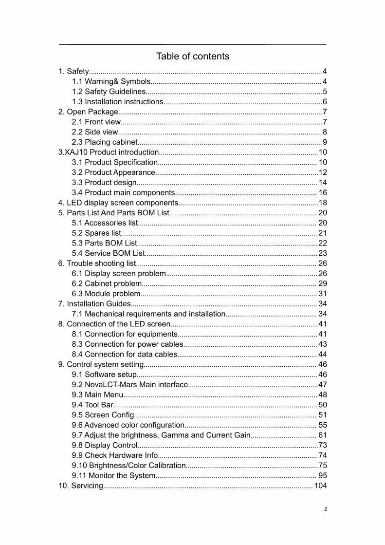
Table of contents1. Safety........................................................................................................................4
1.1 Warning& Symbols........................................................................................ 41.2 Safety Guidelines...........................................................................................51.3 Installation instructions..................................................................................6
2. Open Package.........................................................................................................72.1 Front view........................................................................................................72.2 Side view.........................................................................................................82.3 Placing cabinet...............................................................................................9
3.XAJ10 Product introduction..................................................................................103.1 Product Specification.................................................................................. 103.2 Product Appearance....................................................................................123.3 Product design.............................................................................................143.4 Product main components......................................................................... 16
4. LED display screen components........................................................................185. Parts List And Parts BOM List............................................................................ 20
5.1 Accessories list............................................................................................ 205.2 Spares list..................................................................................................... 215.3 Parts BOM List.............................................................................................225.4 Service BOM List.........................................................................................23
6. Trouble shooting list............................................................................................. 266.1 Display screen problem..............................................................................266.2 Cabinet problem.......................................................................................... 296.3 Module problem...........................................................................................31
7. Installation Guides................................................................................................347.1 Mechanical requirements and installation............................................... 34
8. Connection of the LED screen............................................................................418.1 Connection for equipments........................................................................418.3 Connection for power cables.....................................................................438.4 Connection for data cables........................................................................ 44
9. Control system setting......................................................................................... 469.1 Software setup.............................................................................................469.2 NovaLCT-Mars Main interface...................................................................479.3 Main Menu....................................................................................................489.4 Tool Bar......................................................................................................... 509.5 Screen Config.............................................................................................. 519.6 Advanced color configuration.................................................................... 559.7 Adjust the brightness, Gamma and Current Gain.................................. 619.8 Display Control.............................................................................................739.9 Check Hardware Info.................................................................................. 749.10 Brightness/Color Calibration....................................................................759.11 Monitor the System................................................................................... 95
10. Servicing............................................................................................................104
3
10.1 Cleaning....................................................................................................10410.2 Calibration................................................................................................ 10510.3 Replacement steps.................................................................................106
11. Appendix.............................................................................................................119
4
1. Safety
1.1 Warning& Symbols
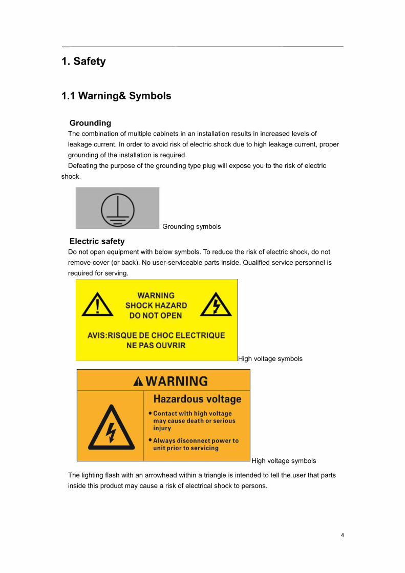
GroundingThe combination of multiple cabinets in an installation results in increased levels ofleakage current. In order to avoid risk of electric shock due to high leakage current, propergrounding of the installation is required.Defeating the purpose of the grounding type plug will expose you to the risk of electric
shock.
Grounding symbols
Electric safetyDo not open equipment with below symbols. To reduce the risk of electric shock, do notremove cover (or back). No user-serviceable parts inside. Qualified service personnel isrequired for serving.
High voltage symbols
High voltage symbols
The lighting flash with an arrowhead within a triangle is intended to tell the user that partsinside this product may cause a risk of electrical shock to persons.

5
1.2 Safety Guidelines
Personal protectionEnsure you understand and follow all the safety guidelines, installation instruction, warningsand symbols.Mind yourself while working with heavy loads and high voltage.Contact with high voltage may cause death or serious injury. Always disconnect power to thedisplay cabinet or cabinets prior to servicing.All personnel at the LED Video Board installation site are required to have personalprotection equipment (PPE) such as hard hats, safety glasses, gloves, harnesses, and otherappropriate safety equipment.
Equipment protectionThis installation must be performed by authorized and qualified technical personnel only.Accredited safety officers must ensure the safety of the site, construction, assembly,connection, use, dismantling, transport etc.Assembly parts are designed for use only with Samsung displays.LEDs use specific materials and manufacturing processing in order to achieve uniqueadvantages.Do not modify and/or replicate any components.Ground the LED display screen before connecting the power source.Contacting displaysthat are not earth-grounded may cause death or serious injury.Do not use the LED display screen ground lugs for installation equipment such as welding
equipment.Structural & mounting components should be kept dry, clean, lubricated (only ifrecommended), coated properly, and maintained in a manner consistent with part design.LED products must be installed and operated in a manner to reply on its design andinspection a routine basis for security, wear, deformation, corrosion and any othercircumstances that may affect the load handling capability of the part.We recommend inspections at regular intervals for all installations and increasing infrequency for more critical installations. A part is damaged which may cause a decrease inload capability. The part must be removed for service or replaced immediately.Always follow LED display screen installation instruction.Contact the support technical person if user has any question regarding the safety of an
application. The manufacturer assumes no liability for incorrect, inadequate, irresponsible or
unsafe assembly of systems.

6
1.3 Installation instructions
InstructionsRead these instructions.Keep these instructions.Heed all warnings.Follow all instructions.Do not block ventilation openings. Please install in accordance with the manufactures
instructions.Avoid installation near heat sources such as radiators, heat registers, stoves, or otherapparatus (including amplifiers) that produce heat. We suggest the user install someequipment to reduce the heat if any.Do not break the safety purpose of polarized or grounding type plugs/sockets. If theprovided sockets/plugs are damaged then replacement of the detective parts must beundertaken immediately.Protect the power/data cords from being taken off or pinched particularly at plugs,convenience receptacles, and the point where they exit from the apparatus. Replacedamaged power/data cords immediately.Only use attachments/accessories specified or provided by the manufacturer.Use with caution during lifting/moving or transporting to avoid damage by possible crash.After receiving the LED display screen, please uncover all the boxes and cases, count andcheck all things compare with the packing list. If there is any problem such as missing ordamaged part, contact the manufacture immediately.Installation guide details are shown in charter 7&8.
7
2. Open Package
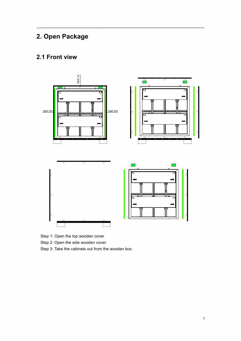
2.1 Front view
Step 1: Open the top wooden coverStep 2: Open the side wooden coverStep 3: Take the cabinets out from the wooden box.
8
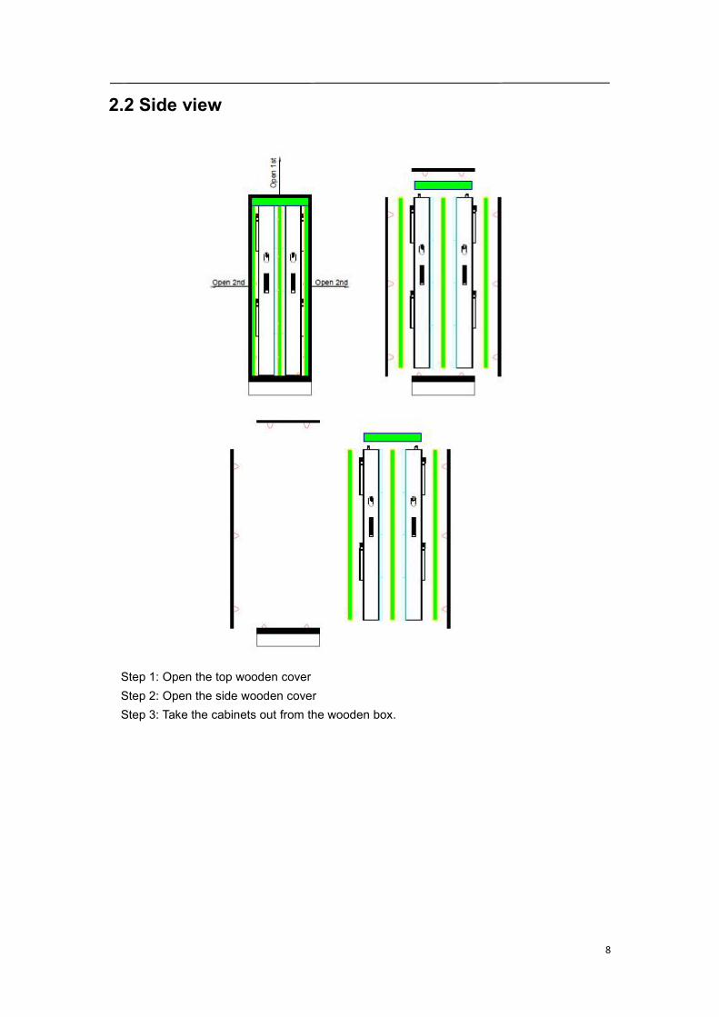
2.2 Side view
Step 1: Open the top wooden coverStep 2: Open the side wooden coverStep 3: Take the cabinets out from the wooden box.
9
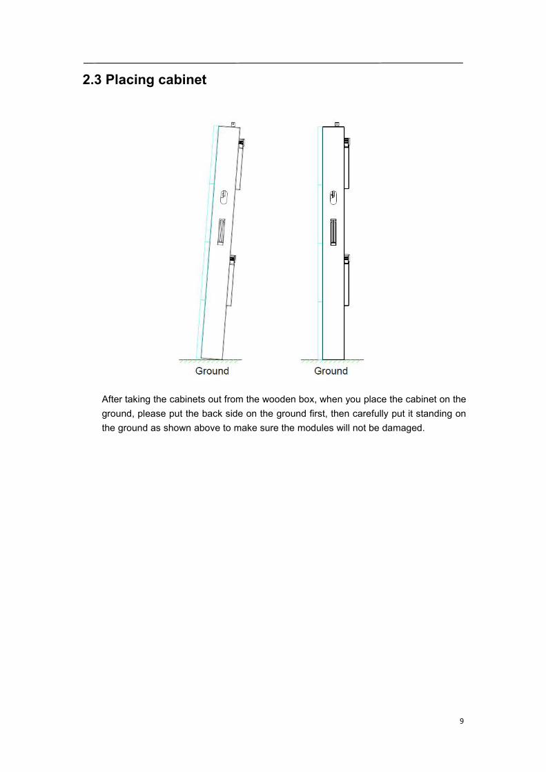
2.3 Placing cabinet
After taking the cabinets out from the wooden box, when you place the cabinet on theground, please put the back side on the ground first, then carefully put it standing onthe ground as shown above to make sure the modules will not be damaged.
10
3.XAJ10 Product introduction
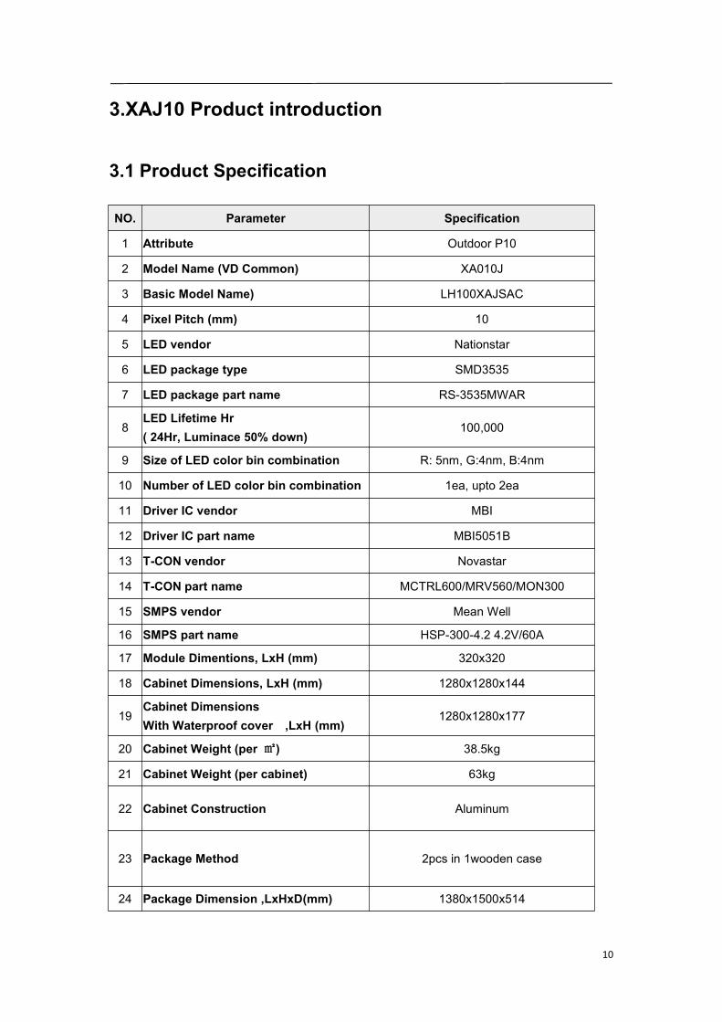
3.1 Product Specification
NO. Parameter Specification
1 Attribute Outdoor P10
2 Model Name (VD Common) XA010J
3 Basic Model Name) LH100XAJSAC
4 Pixel Pitch (mm) 10
5 LED vendor Nationstar
6 LED package type SMD3535
7 LED package part name RS-3535MWAR
8LED Lifetime Hr( 24Hr, Luminace 50% down)
100,000
9 Size of LED color bin combination R: 5nm, G:4nm, B:4nm
10 Number of LED color bin combination 1ea, upto 2ea
11 Driver IC vendor MBI
12 Driver IC part name MBI5051B
13 T-CON vendor Novastar
14 T-CON part name MCTRL600/MRV560/MON300
15 SMPS vendor Mean Well
16 SMPS part name HSP-300-4.2 4.2V/60A
17 Module Dimentions, LxH (mm) 320x320
18 Cabinet Dimensions, LxH (mm) 1280x1280x144
19Cabinet DimensionsWith Waterproof cover ,LxH (mm)
1280x1280x177
20 Cabinet Weight (per ㎡) 38.5kg
21 Cabinet Weight (per cabinet) 63kg
22 Cabinet Construction Aluminum
23 Package Method 2pcs in 1wooden case
24 Package Dimension ,LxHxD(mm) 1380x1500x514
11
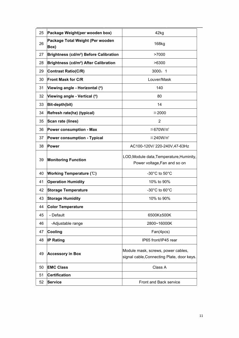
25 Package Weight(per wooden box) 42kg
26Package Total Weight (Per woodenBox)
168kg
27 Brightness (cd/m²) Before Calibration >7000
28 Brightness (cd/m²) After Calibration >6300
29 Contrast Ratio(C/R) 3000:1
30 Front Mask for C/R Louver/Mask
31 Viewing angle - Horizontal (o) 140
32 Viewing angle - Vertical (o) 80
33 Bit-depth(bit) 14
34 Refresh rate(hz) (typical) ≧2000
35 Scan rate (lines) 2
36 Power consumption - Max ≦670W/㎡
37 Power consumption - Typical ≦240W/㎡
38 Power AC100-120V/ 220-240V,47-63Hz
39 Monitoring FunctionLOD,Module data,Temperature,Huminity,
Power voltage,Fan and so on
40 Working Temperature (℃) -30°C to 50°C
41 Operation Humidity 10% to 90%
42 Storage Temperature -30°C to 60°C
43 Storage Humidity 10% to 90%
44 Color Temperature
45 - Default 6500K±500K
46 -Adjustable range 2800~16000K
47 Cooling Fan(4pcs)
48 IP Rating IP65 front/IP45 rear
49 Accessory in BoxModule mask, screws, power cables,signal cable,Connecting Plate, door keys.
50 EMC Class Class A
51 Certification52 Service Front and Back service

12
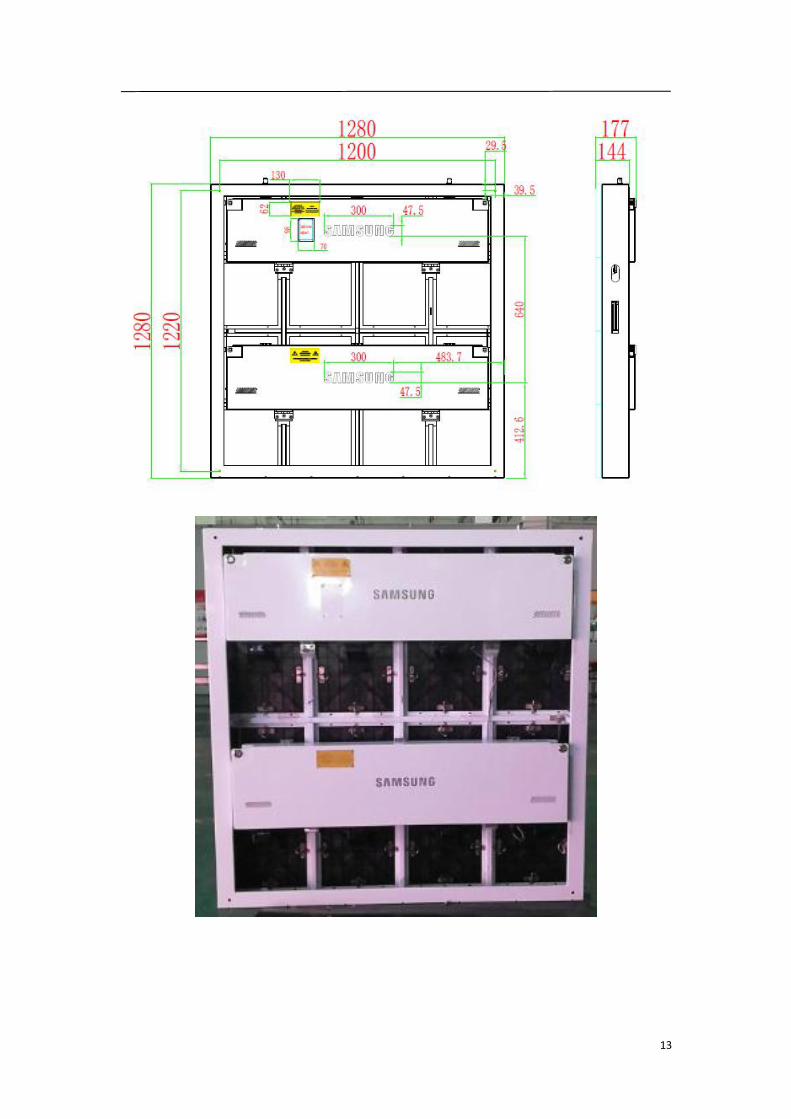
3.2 Product Appearance
13
14
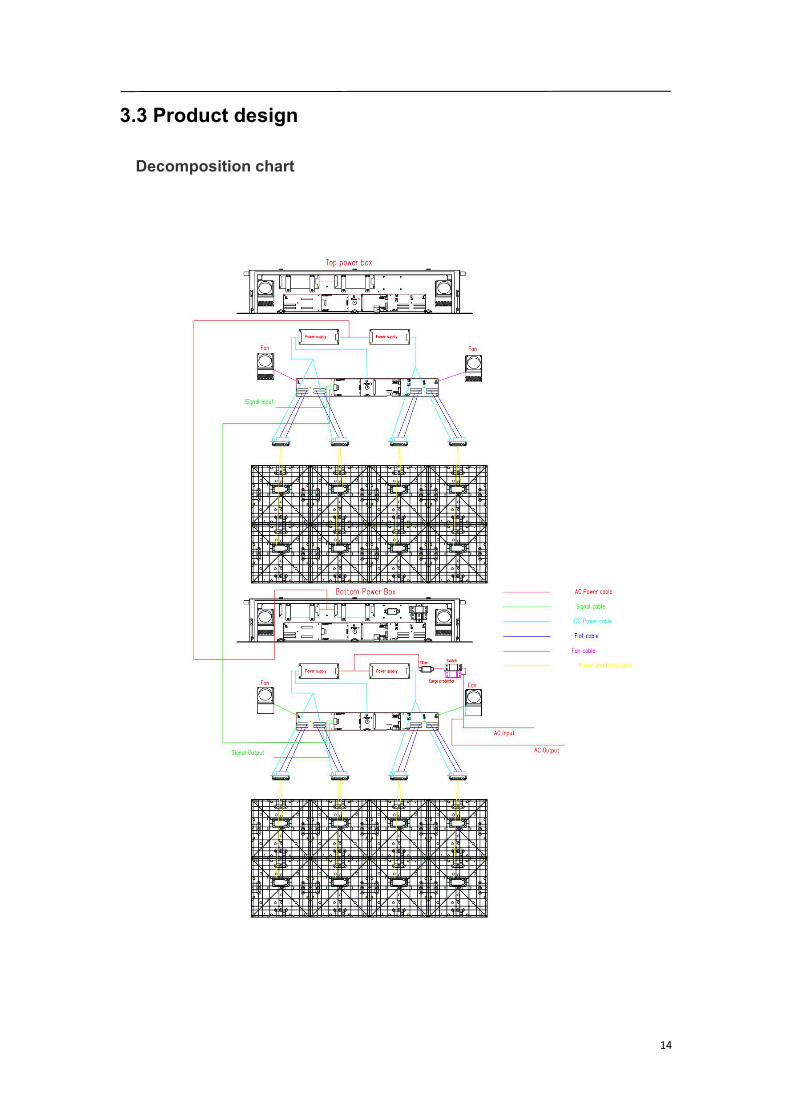
3.3 Product design
Decomposition chart
15
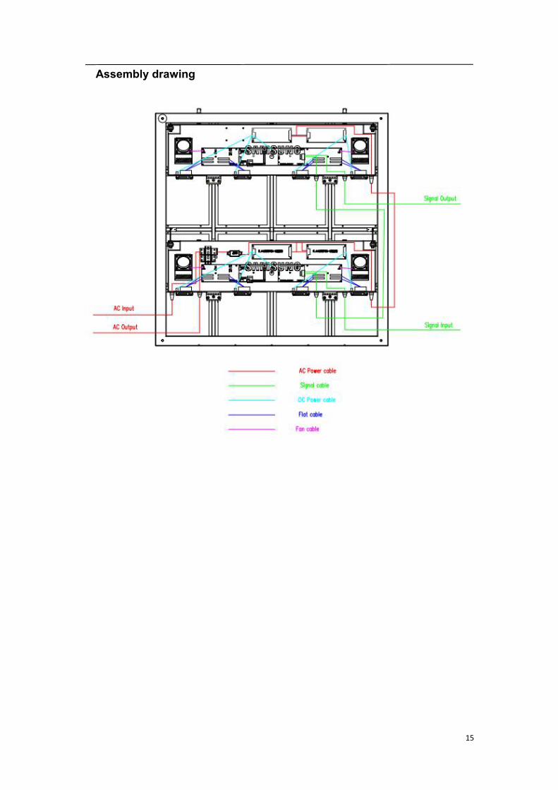
Assembly drawing
16
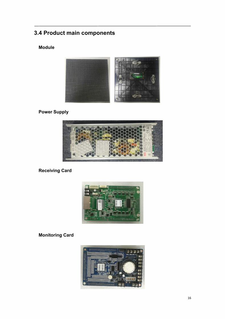
3.4 Product main components
Module
Power Supply
Receiving Card
Monitoring Card

17
Fan
Hub board
Power-data cables(16pcs)
DC power cables (8PCS)and Flat cables (16 pcs)
18
4. LED display screen components
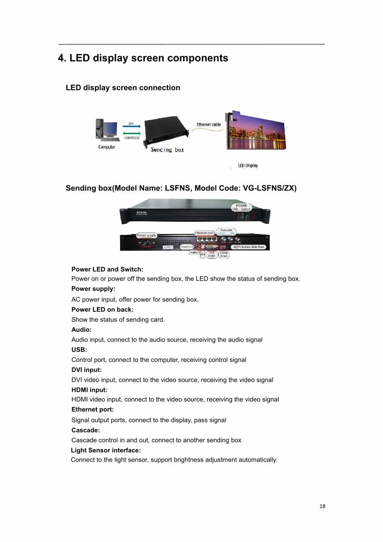
LED display screen connection
Sending box(Model Name: LSFNS, Model Code: VG-LSFNS/ZX)
Power LED and Switch:Power on or power off the sending box, the LED show the status of sending box.Power supply:AC power input, offer power for sending box.Power LED on back:Show the status of sending card.Audio:Audio input, connect to the audio source, receiving the audio signalUSB:Control port, connect to the computer, receiving control signalDVI input:DVI video input, connect to the video source, receiving the video signalHDMI input:HDMI video input, connect to the video source, receiving the video signalEthernet port:Signal output ports, connect to the display, pass signalCascade:Cascade control in and out, connect to another sending boxLight Sensor interface:Connect to the light sensor, support brightness adjustment automatically.
19
Function of sending box:1. HDMI/DVI input;2. HDMI/external audio input;3. 12bit/10bit/8bit HD video source;4. Resolution supported: 2048x1152, 1920x1200, 2560x960;5. Resolution supported: 1440x900;6. 1 light sensor interface;7. Cascading supported;8. 18bit gray scale processing and presentation;9. Video format:RGB, YCrCb4:2:2, YCrCb4:4:4;10. Standard 1U housing; independent power supply;1U chassis, Size: 482.6mm(width)*44.45mm(height)*250mm(depth).dd Weight: 4.15KgNet weight: 2.7Kg
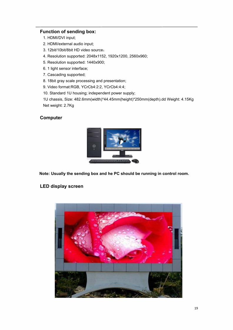
Computer
Note: Usually the sending box and he PC should be running in control room.
LED display screen

20
5. Parts List And Parts BOM List
5.1 Accessories list
Sending box U Disk 3 core plug DVI cable
BN81-15303A BN81-15333A BN81-15312A BN81-15310A
R2S8-22-1721 2S8-22-2038 R2J8-22-0125 R2L3-27-0104
USB cable AC power input cable Signal input cable AC power cascade cable
BN81-15311A Different code by different project
R2L3-27-0105 Different code by different project 3D2-22-8582
Signal cascade cable Connect plate M10 Bowls Key for power boxR3D3-23-1931 R2J8-42-10000 R2W8-22-0466 R2W8-29-3277
Remark: The final quantity is subject to each order.

21
5.2 Spares list
Sending box Receiving card hub board Module
BN81-15303A
R2S8-22-1721 R4B3-10-0305 R3C6-88-10006 R4X3-08-10000
Power supply Fan LED package Driver ICBN81-15302A BN81-15325A
R2D8-22-0159 R2F8-88-0438 R3G1-27-0054 R2K2-22-0219
Mask Screws for Mask AC power input cable Signal cascade cableBN81-15336A Different code by different project
L2A8-24-00000 R2W8-22-1410 Different code by different project
AC-power cascade cable Signal cascade cable Power-data cable Transfer board3D2-22-8582 R3D3-23-1931 R3D2-23-10002 R3C6-88-10005
DC cable 1 DC cable 2 Flat cable Monitoring card3D2-22-10034(...) 3D4-22-0069 R2S8-22-2170
Remark: The final quantity is subject to each order. 3% spare parts will be sent within each
order.
22
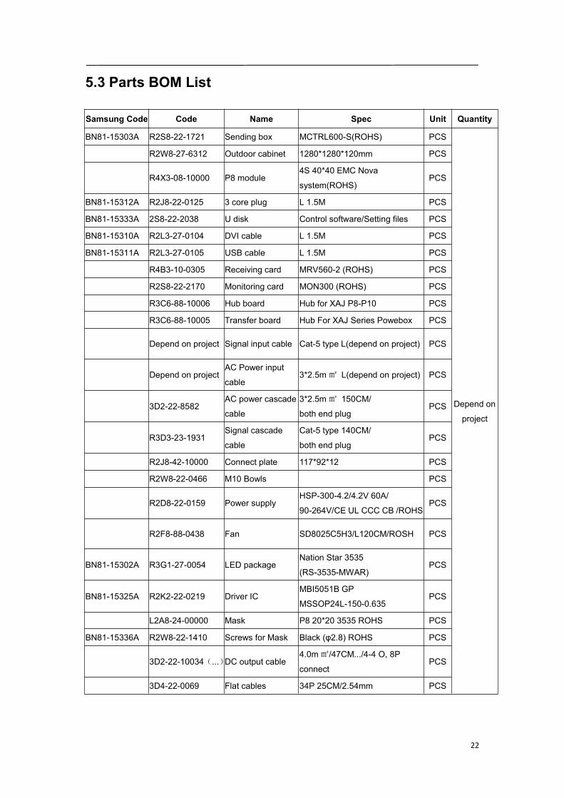
5.3 Parts BOM List
Samsung Code Code Name Spec Unit Quantity
BN81-15303A R2S8-22-1721 Sending box MCTRL600-S(ROHS) PCS
Depend on
project
R2W8-27-6312 Outdoor cabinet 1280*1280*120mm PCS
R4X3-08-10000 P8 module4S 40*40 EMC Nova
system(ROHS)PCS
BN81-15312A R2J8-22-0125 3 core plug L 1.5M PCS
BN81-15333A 2S8-22-2038 U disk Control software/Setting files PCS
BN81-15310A R2L3-27-0104 DVI cable L 1.5M PCS
BN81-15311A R2L3-27-0105 USB cable L 1.5M PCS
R4B3-10-0305 Receiving card MRV560-2 (ROHS) PCS
R2S8-22-2170 Monitoring card MON300 (ROHS) PCS
R3C6-88-10006 Hub board Hub for XAJ P8-P10 PCS
R3C6-88-10005 Transfer board Hub For XAJ Series Powebox PCS
Depend on project Signal input cable Cat-5 type L(depend on project) PCS
Depend on projectAC Power input
cable3*2.5m㎡ L(depend on project) PCS
3D2-22-8582AC power cascade
cable
3*2.5m㎡ 150CM/
both end plugPCS
R3D3-23-1931Signal cascade
cable
Cat-5 type 140CM/
both end plugPCS
R2J8-42-10000 Connect plate 117*92*12 PCS
R2W8-22-0466 M10 Bowls PCS
R2D8-22-0159 Power supplyHSP-300-4.2/4.2V 60A/
90-264V/CE UL CCC CB /ROHSPCS
R2F8-88-0438 Fan SD8025C5H3/L120CM/ROSH PCS
BN81-15302A R3G1-27-0054 LED packageNation Star 3535
(RS-3535-MWAR)PCS
BN81-15325A R2K2-22-0219 Driver ICMBI5051B GP
MSSOP24L-150-0.635PCS
L2A8-24-00000 Mask P8 20*20 3535 ROHS PCS
BN81-15336A R2W8-22-1410 Screws for Mask Black (φ2.8) ROHS PCS
3D2-22-10034(...)DC output cable4.0m㎡/47CM.../4-4 O, 8P
connectPCS
3D4-22-0069 Flat cables 34P 25CM/2.54mm PCS
23
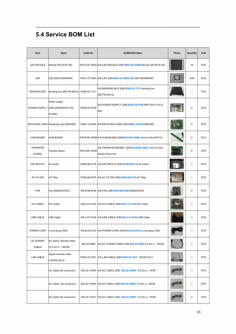
5.4 Service BOM List
Item Spec Code.No SAMSUNG Spec Photo Quantity Unit
LED MOUDLE Module (P8 40*40 4S) R4X3-08-10000 A/S-LED MOUDLE:JDM,R4X3-08-10000,Module (P8 40*40 4S) 16 PCS
LED LED (RS-3535MWAR) R3G1-27-0054 A/S-LED:JDM,R3G1-27-0054,LED (RS-3535MWAR) 1024 PCS
SENDING BOX Sending box (MCTRL600-S) R2S8-22-1721A/S-SENDING BOX:JDM,R2S8-22-1721,Sending box
(MCTRL600-S)1 PCS
POWER SUPPLY
Power supply
(GW-XSP300WV5-V03
5V/60A)
R2D8-22-0159A/S-POWER SUPPLY:JDM,R2D8-22-0159,HSP-300-4.2/4.2V
60A4 PCS
RECEVING CARD Receiving card (MRV560) R4B3-10-0305 A/S-RECEVING CARD:JDM,R4B3-10-0305,MRV560 2 PCS
HUB BOARD HUB BOARD R3C6-88-10006 A/S-HUB BOARD:JDM,R3C6-88-10006 ,Hub for XAJ-P8-P10 2 PCS
TRANSFER
BOARDTransfer Board R3C6-88-10005
A/S-TRANSFER BOARD :JDM,R3C6-88-10005 ,Hub For XAJ
Series Power box8 PCS
AIR SWITCH Air switch R2S9-88-0178 A/S-AIR SWITCH:JDM,R2S9-88-0178,Air switch 1 PCS
AC FILTER AC Filter R2S9-88-0375 A/S-AC FILTER:JDM,R2S9-88-0375,AC Filter 1 PCS
FAN Fan (SD8025C5H3) R2F8-88-0438 A/S-FAN:JDM,R2F8-88-0438,SD8025C5H3 4 PCS
DVI CABLE DVI Cable R2L3-27-0104 A/S-DVI CABLE:JDM,R2L3-27-0104,DVI Cable 1 PCS
USB CABLE USB Cable R2L3-27-0105 A/S-USB CABLE:JDM,R2L3-27-0105,USB Cable 1 PCS
POWER CORD 3 core plug (VDE) R2J8-22-0125 A/S-POWER CORD:JDM,R2J8-22-0125,3 core plug (VDE) 1 PCS
AC POWER
CABLE
AC power cascade cable
(3*2.5m㎡ 150CM)3D2-22-8582 A/S-AC POWER CABLE:JDM,3D2-22-8582,3*2.5m㎡ 150CM 1 PCS
LAN CABLESignal cascade cable
(140CM Cat-5)R3D3-23-1931 A/S-LAN CABLE:JDM,R3D3-23-1931 ,140CM Cat-5 1 PCS
AC Cable (No conenctor) 3D2-22-10045 A/S-AC CABLE:JDM, 3D2-22-10045 ,3*2.5m㎡ 10CM 1 PCS
AC Cable ( No conenctor) 3D2-22-10046 A/S-AC CABLE:JDM,3D2-22-10046 ,3*2.5m ㎡ 40CM 1 PCS
AC Cable (No conenctor) 3D2-22-10047 A/S-AC CABLE:JDM, 3D2-22-10047 ,3*2.5m㎡ 10CM 2 PCS
24
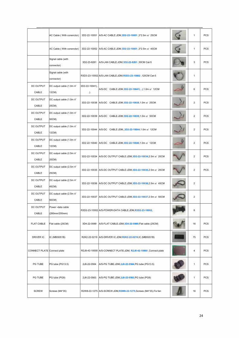
AC Cable ( With conenctor) 3D2-22-10051 A/S-AC CABLE:JDM,3D2-22-10051 ,3*2.5m ㎡ 25CM 1 PCS
AC Cable ( With conenctor) 3D2-22-10052 A/S-AC CABLE:JDM,3D2-22-10051 ,3*2.5m ㎡ 40CM 1 PCS
Signal cable (with
connector)3D2-23-8261 A/S-LAN CABLE:JDM,3D2-22-8261 ,30CM Cat-5 3 PCS
Signal cable (with
connector)R3D3-23-10002 A/S-LAN CABLE:JDM,R3D3-23-10002 ,120CM Cat-5 1
DC OUTPUT
CABLE
DC output cable (1.0m㎡
12CM)
3D2-22-10041(..
.)A/S-DC CABLE:JDM,3D2-22-10041(...),1.0m ㎡ 12CM 6 PCS
DC OUTPUT
CABLE
DC output cable (1.0m㎡
25CM)3D2-22-10038 A/S-DC CABLE:JDM,3D2-22-10038,1.0m ㎡ 25CM 2 PCS
DC OUTPUT
CABLE
DC output cable (1.0m㎡
50CM)3D2-22-10039 A/S-DC CABLE:JDM,3D2-22-10039,1.0m ㎡ 50CM 2 PCS
DC OUTPUT
CABLE
DC output cable (1.0m㎡
12CM)3D2-22-10044 A/S-DC CABLE:JDM,,3D2-22-10044,1.0m ㎡ 12CM 2 PCS
DC OUTPUT
CABLE
DC output cable (1.0m㎡
12CM)3D2-22-10040 A/S-DC CABLE:JDM,3D2-22-10040,1.0m ㎡ 12CM 2 PCS
DC OUTPUT
CABLE
DC output cable (2.5m㎡
20CM)3D2-22-10034 A/S-DC OUTPUT CABLE:JDM,3D2-22-10034,2.5m㎡ 20CM 2 PCS
DC OUTPUT
CABLE
DC output cable (2.5m㎡
25CM)3D2-22-10035 A/S-DC OUTPUT CABLE:JDM,3D2-22-10035,2.5m㎡ 20CM 2 PCS
DC OUTPUT
CABLE
DC output cable (2.5m㎡
45CM)3D2-22-10036 A/S-DC OUTPUT CABLE:JDM,3D2-22-10036,2.5m㎡ 45CM 2
DC OUTPUT
CABLE
DC output cable (2.5m㎡
50CM)3D2-22-10037 A/S-DC OUTPUT CABLE:JDM,3D2-22-10037,2.5m㎡ 50CM 2
DC OUTPUT
CABLE
Power -data cable
(260mm/200mm)R3D2-23-10002 A/S-POWER-DATA CABLE:JDM,R3D2-23-10002, 8
FLAT CABLE Flat cable (25CM) 3D4-22-0069 A/S-FLAT CABLE:JDM,3D4-22-0069,Flat cable (25CM) 16 PCS
DRIVER IC IC (MBI5051B) R2K2-22-0219 A/S-DRIVER IC:JDM,R2K2-22-0219,IC (MBI5051B) 75 PCS
CONNECT PLATE Connect plate R2J8-42-10000 A/S-CONNECT PLATE:JDM, R2J8-42-10000 ,Connect plate 4 PCS
PG TUBE PG tube (PG13.5) 2J8-22-0564 A/S-PG TUBE:JDM,2J8-22-0564,PG tube (PG13.5) 1 PCS
PG TUBE PG tube (PG9) 2J8-22-0563 A/S-PG TUBE:JDM,2J8-22-0563,PG tube (PG9) 1 PCS
SCREW Screws (M4*35) R2W8-22-1275 A/S-SCREW:JDM,R2W8-22-1275,Screws (M4*35),Fix fan 16 PCS
25
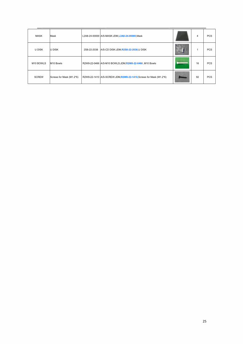
MASK Mask L2A8-24-00000 A/S-MASK:JDM,L2A8-24-00000,Mask 4 PCS
U DISK U DISK 2S8-22-2038 A/S-CD DISK:JDM,R2S8-22-2038,U DISK 1 PCS
M10 BOWLS M10 Bowls R2W8-22-0466 A/S-M10 BOWLS:JDM,R2W8-22-0466 ,M10 Bowls 16 PCS
SCREW Screws for Mask (M1.2*6) R2W8-22-1410 A/S-SCREW:JDM,R2W8-22-1410,Screws for Mask (M1.2*6) 92 PCS

26
6. Trouble shooting list
6.1 Display screen problem
The whole display screen cannot light up
Check if the display screen is power on.Check if the connection is broken between Sending box and the display screen,Check if the sending box is normalCheck if the first cabinet is working normally in the display screenCheck if the brightness setting is 0%Check if the software setting is correct.The whole display screen is blinking
Check if the connection is broken between PC and Sending boxCheck if the connection is broken between Sending box and the display screenCheck if the sending box is normalCheck if the first cabinet is working normally in the display screenCheck if the software setting is correct
27
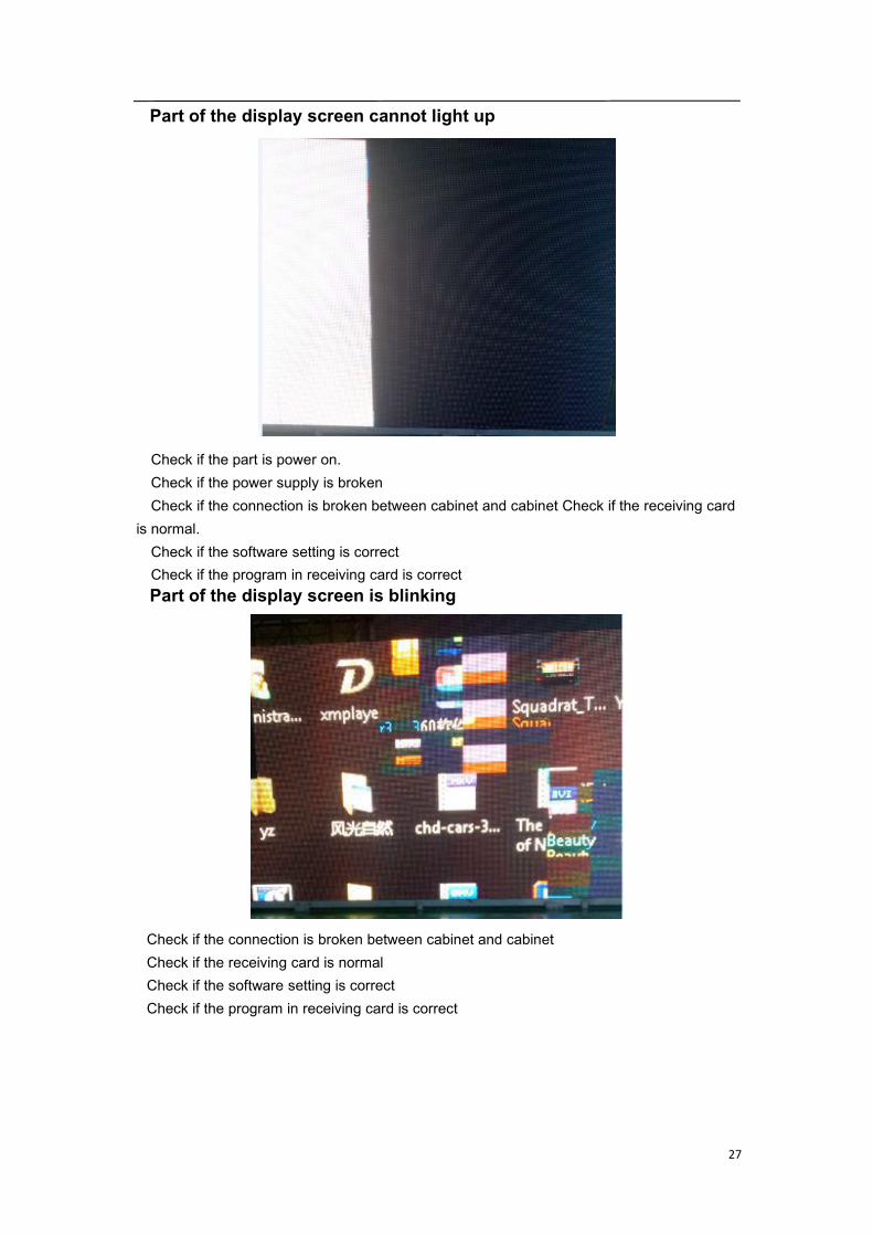
Part of the display screen cannot light up
Check if the part is power on.Check if the power supply is brokenCheck if the connection is broken between cabinet and cabinet Check if the receiving card
is normal.Check if the software setting is correctCheck if the program in receiving card is correctPart of the display screen is blinking
Check if the connection is broken between cabinet and cabinetCheck if the receiving card is normalCheck if the software setting is correctCheck if the program in receiving card is correct

28
The display screen is out of control
Check if the USB cable is connected wellCheck if the USB cable is brokenCheck if the software is running wellThe display screen display wrong image
Check if the connection table setting is correctCheck if the software setting is correctCheck if the program in receiving card is correct

29
6.2 Cabinet problem
The cabinet cannot light up
Check if the cabinet is power onCheck if the connection is broken between cabinet to cabinet Check if the receiving card is
normalCheck if the power supply is broken in cabinetCheck if the program for receiving card is correctThe cabinet is blinking
Check if the receiving card is brokenCheck if the connection is broken between cabinet to cabinetCheck if the program for receiving card is correct
30
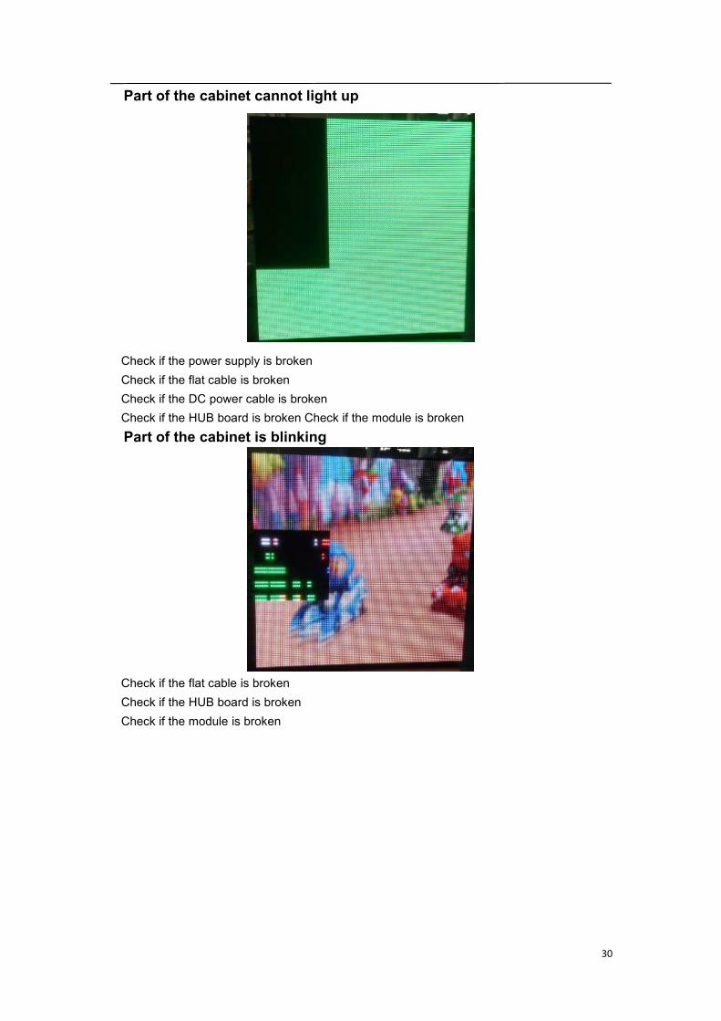
Part of the cabinet cannot light up
Check if the power supply is brokenCheck if the flat cable is brokenCheck if the DC power cable is brokenCheck if the HUB board is broken Check if the module is brokenPart of the cabinet is blinking
Check if the flat cable is brokenCheck if the HUB board is brokenCheck if the module is broken
31
6.3 Module problem
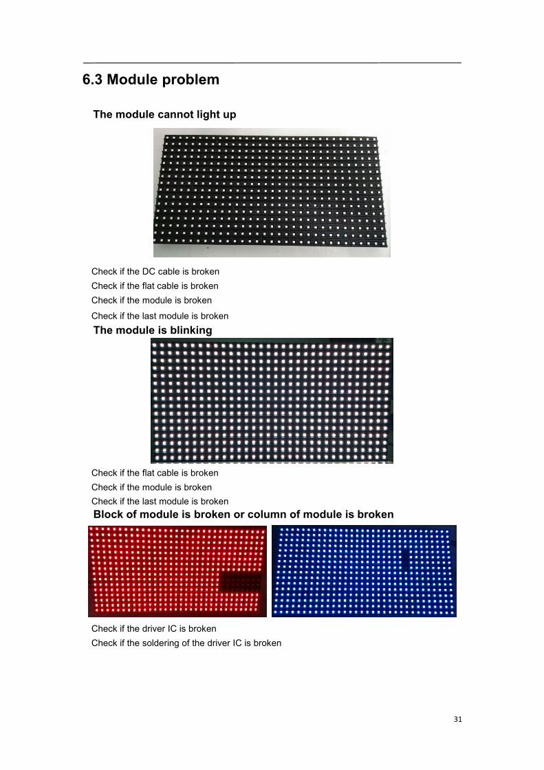
The module cannot light up
Check if the DC cable is brokenCheck if the flat cable is brokenCheck if the module is broken
Check if the last module is brokenThe module is blinking
Check if the flat cable is brokenCheck if the module is brokenCheck if the last module is brokenBlock of module is broken or column of module is broken
Check if the driver IC is brokenCheck if the soldering of the driver IC is broken
32
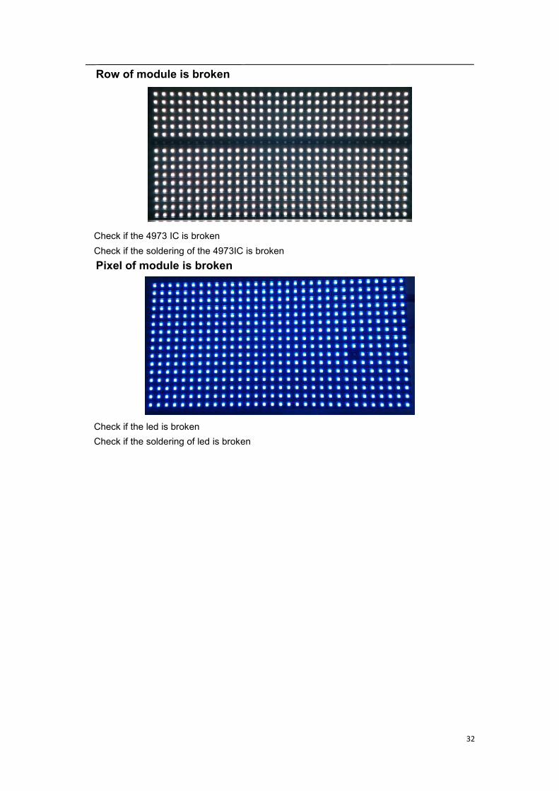
Row of module is broken
Check if the 4973 IC is brokenCheck if the soldering of the 4973IC is brokenPixel of module is broken
Check if the led is brokenCheck if the soldering of led is broken
33
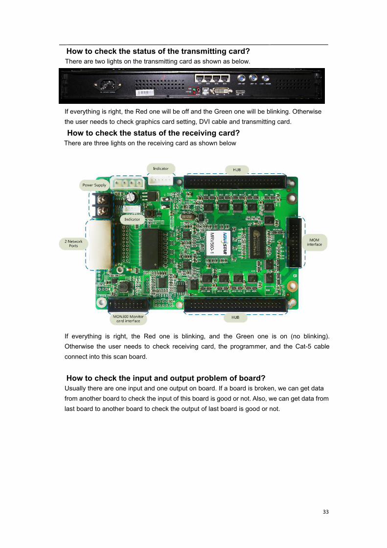
How to check the status of the transmitting card?There are two lights on the transmitting card as shown as below.
If everything is right, the Red one will be off and the Green one will be blinking. Otherwisethe user needs to check graphics card setting, DVI cable and transmitting card.
How to check the status of the receiving card?There are three lights on the receiving card as shown below
If everything is right, the Red one is blinking, and the Green one is on (no blinking).Otherwise the user needs to check receiving card, the programmer, and the Cat-5 cableconnect into this scan board.
How to check the input and output problem of board?Usually there are one input and one output on board. If a board is broken, we can get datafrom another board to check the input of this board is good or not. Also, we can get data fromlast board to another board to check the output of last board is good or not.

34
7. Installation Guides
7.1 Mechanical requirements and installation
Support structureThe support structure has to be provided and installed by the customer because they varyfrom project to project. The following issues must be considered:Weight tolerances: Ensure that the support structure and the floor on which or the wallagainst which the support structure has to be installed, is qualified to handle the completeweight of the LED display screen.(which can be provided by manufacturer. Environmentalconditions: Humidity, wind, temperatures, rain, snow etc.Location: Outdoor/.Indoor, altitude, etc. Usually, for outdoor display screen, the customershould build top cover and side cover for IP protection (Including waterproof and dustproof)Ground stabilityFront clearances: For making sure there is sufficient free area in front of the LED displayscreen and respect the maximum viewing angles and distance.Local regulations regarding such installationTools for installationPlease prepare below tools before installationSlot type screwdriver, Philips type screwdriver, spanner, Hexagonal bar, Hexagonal head
screwdriver, scissors, pincers, wire cutters, hammer, electric drill, electric welding,
Multi-meter, etc.
35
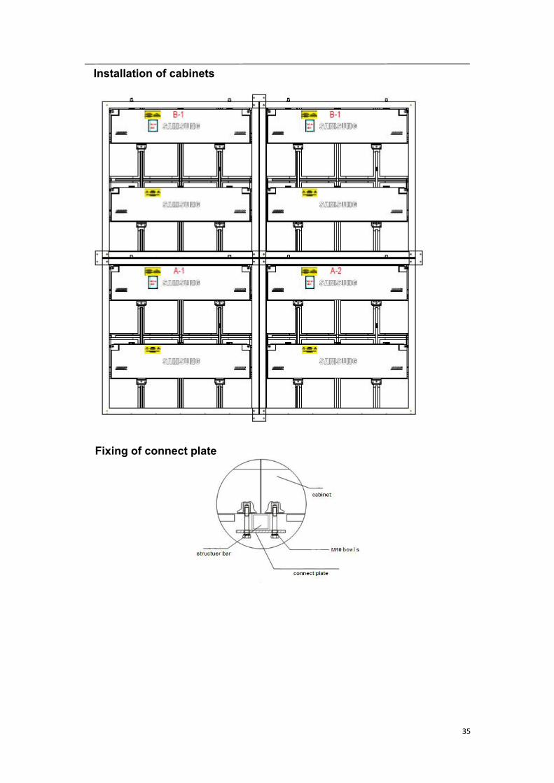
Installation of cabinets
Fixing of connect plate
36
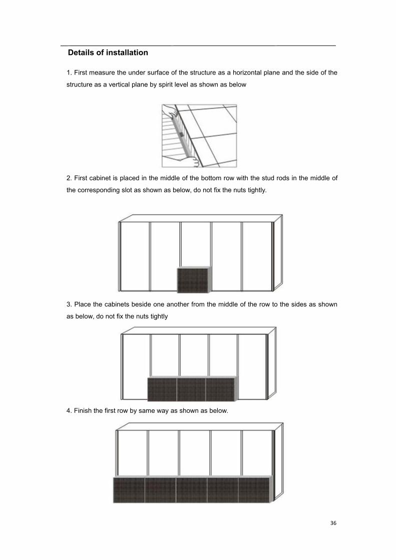
Details of installation
1. First measure the under surface of the structure as a horizontal plane and the side of the
structure as a vertical plane by spirit level as shown as below
2. First cabinet is placed in the middle of the bottom row with the stud rods in the middle of
the corresponding slot as shown as below, do not fix the nuts tightly.
3. Place the cabinets beside one another from the middle of the row to the sides as shown
as below, do not fix the nuts tightly
4. Finish the first row by same way as shown as below.
37
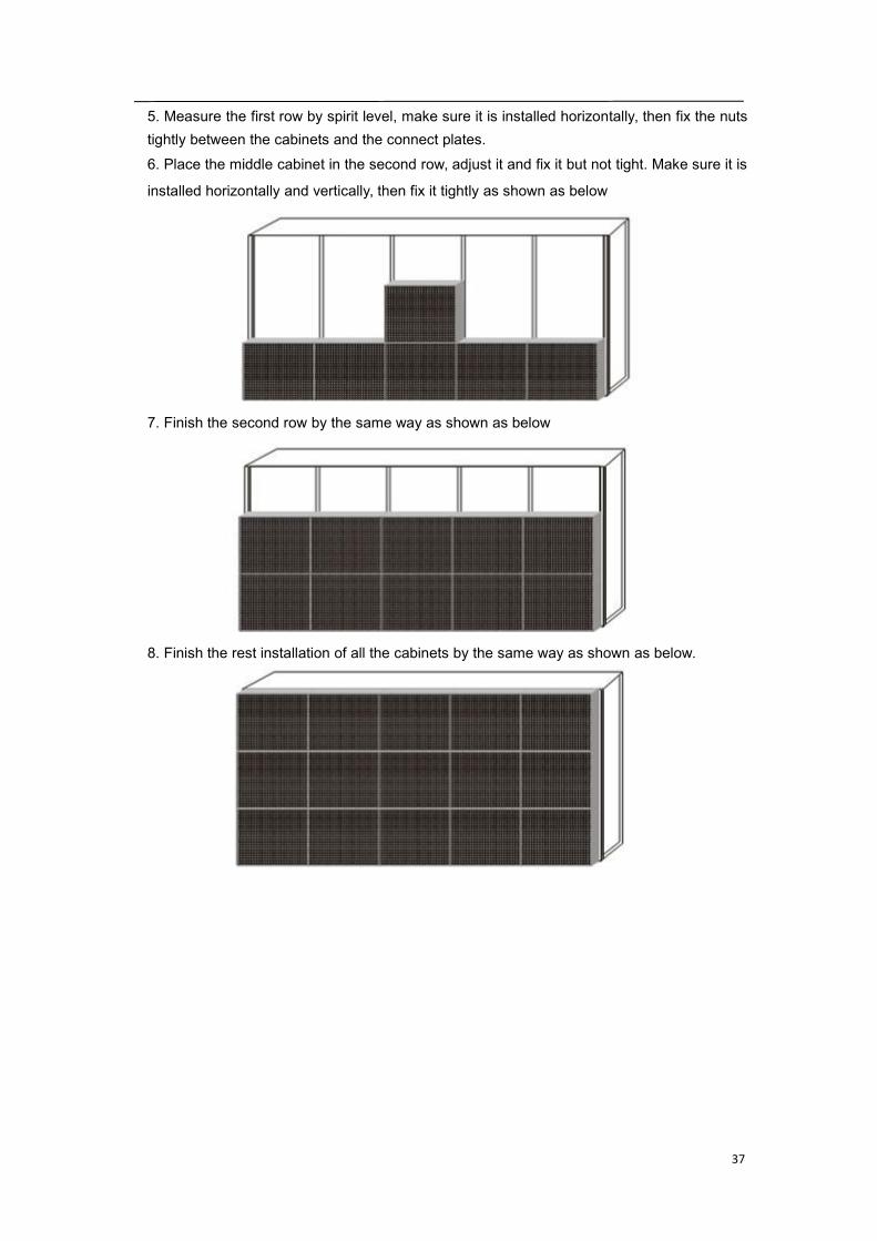
5. Measure the first row by spirit level, make sure it is installed horizontally, then fix the nutstightly between the cabinets and the connect plates.6. Place the middle cabinet in the second row, adjust it and fix it but not tight. Make sure it is
installed horizontally and vertically, then fix it tightly as shown as below
7. Finish the second row by the same way as shown as below
8. Finish the rest installation of all the cabinets by the same way as shown as below.

38
7.2 Electrical requirements
Power systemPower voltage must be in the range of the specification value.It is recommended to use a power distribution system (a power distribution system with aseparate neutral and grounding conductor in order to avoid large ground current loopsdue to voltage differences in the neutral conductor.The total electrical installation should be protected by an appropriately rated disconnectswitch, circuit breakers.The electrical installation must only be performed by a qualified electrician. Electricalconnections must comply with all applicable national and local codes.
Cabling & ConnectionAll internal cabling must be properly connected and seated.All power wiring must be from circuit breaker protected lines. Do not connect to anunprotect circuit.Do not route power and communication wires in the same conduit. Separate conduitsmust be run for communication wires and power wires. However, fiber optic wire may berun in the same conduit with power wires.
GroundingThe LED display screen must be properly grounded according the applicable national andlocal codes.Properly grounding every display cabinet is necessary as it is essential to prevent shock,shock hazards, and fire hazards.
Lighting Strike ProtectionA LED display screen cabinet bonder to an earth ground aims to dissipate the highvoltage and current from a lighting strike. The resistance of the grounding electrode mustbe as low as possible. However, damage can still occur to a LED display screen cabinet`selectronic equipment from lighting voltage transients.Though some surge protection is incorporated into a LED display screen in order to
protect the display from high voltage lighting transients, surge protectors need to be
installed.
39
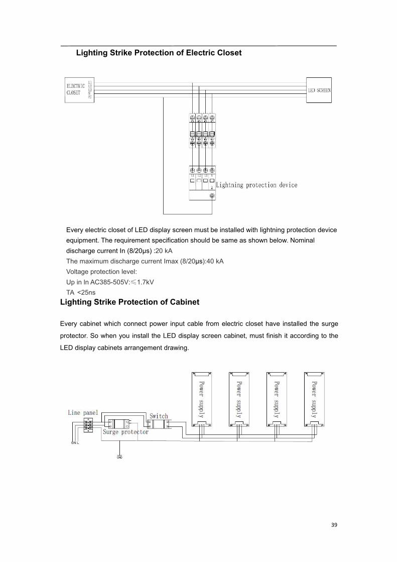
Lighting Strike Protection of Electric Closet
Every electric closet of LED display screen must be installed with lightning protection deviceequipment. The requirement specification should be same as shown below. Nominaldischarge current In (8/20µs) :20 kAThe maximum discharge current Imax (8/20µs):40 kAVoltage protection level:Up in ln AC385-505V:≤1.7kVTA ˂25ns
Lighting Strike Protection of Cabinet
Every cabinet which connect power input cable from electric closet have installed the surge
protector. So when you install the LED display screen cabinet, must finish it according to the
LED display cabinets arrangement drawing.
40
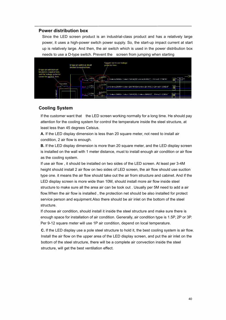
Power distribution boxSince the LED screen product is an industrial-class product and has a relatively largepower, it uses a high-power switch power supply. So, the start-up impact current at startup is relatively large. And then, the air switch which is used in the power distribution boxneeds to use a D-type switch. Prevent the screen from jumping when starting
Cooling SystemIf the customer want that the LED screen working normally for a long time. He should payattention for the cooling system for control the temperature inside the steel structure, atleast less than 45 degrees Celsius.A. If the LED display dimension is less than 20 square meter, not need to install aircondition, 2 air flow is enough.B. If the LED display dimension is more than 20 square meter, and the LED display screenis installed on the wall with 1 meter distance, must to install enough air condition or air flowas the cooling system.If use air flow , it should be installed on two sides of the LED screen. At least per 3-4Mheight should install 2 air flow on two sides of LED screen, the air flow should use suctiontype one. it means the air flow should take out the air from structure and cabinet. And if theLED display screen is more wide than 10M, should install more air flow inside steelstructure to make sure all the area air can be took out . Usually per 5M need to add a airflow.When the air flow is installed , the protection net should be also installed for protectservice person and equipment.Also there should be air inlet on the bottom of the steelstructure.If choose air condition, should install it inside the steel structure and make sure there isenough space for installation of air condition. Generally, air condition type is 1.5P, 2P or 3P.Per 9-12 square meter will use 1P air condition, depend on local temperature.
C. If the LED display use a pole steel structure to hold it, the best cooling system is air flow.Install the air flow on the upper area of the LED display screen, and put the air inlet on thebottom of the steel structure, there will be a complete air convection inside the steelstructure, will get the best ventilation effect.

41
8. Connection of the LED screen
8.1 Connection for equipments
Connection between Sending box and PC
42
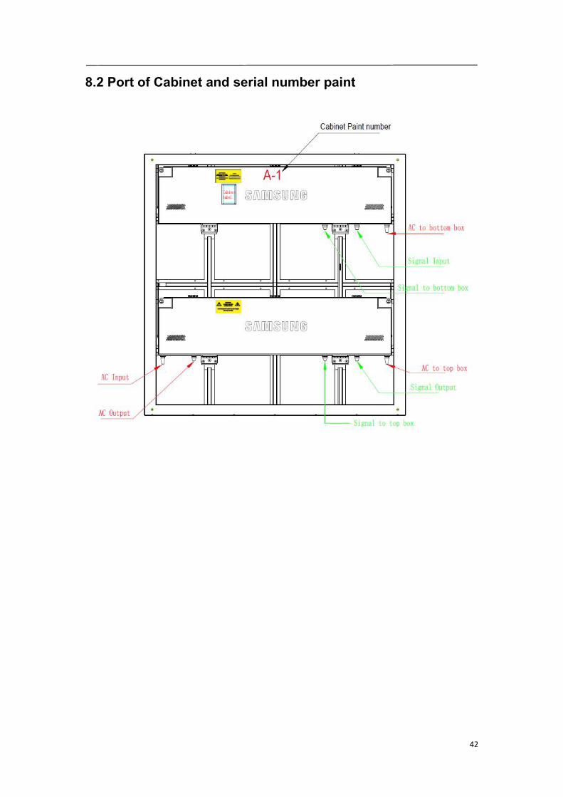
8.2 Port of Cabinet and serial number paint

43
8.3 Connection for power cables
Usually the length of the AC input cable depend on the distance between the powerdistribution and LED display screen, it is not certain.The AC cascade cable:3*2.5m㎡ 150CM/both end plugAttention: For 220-240V AC power voltage countries and areas, each AC input cable can offerpower for 4 cabinets. But each AC input cable only can offer power for 2 cabinets in 100-120VAC power voltage countries and areas.For XAJ product, every cabinet has one surge protect in the bottom power box.
44
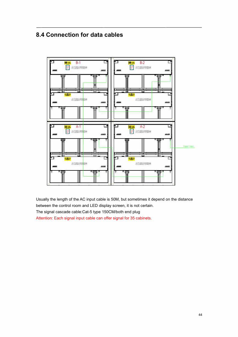
8.4 Connection for data cables
Usually the length of the AC input cable is 50M, but sometimes it depend on the distancebetween the control room and LED display screen, it is not certain.The signal cascade cable:Cat-5 type 150CM/both end plugAttention: Each signal input cable can offer signal for 35 cabinets.
45
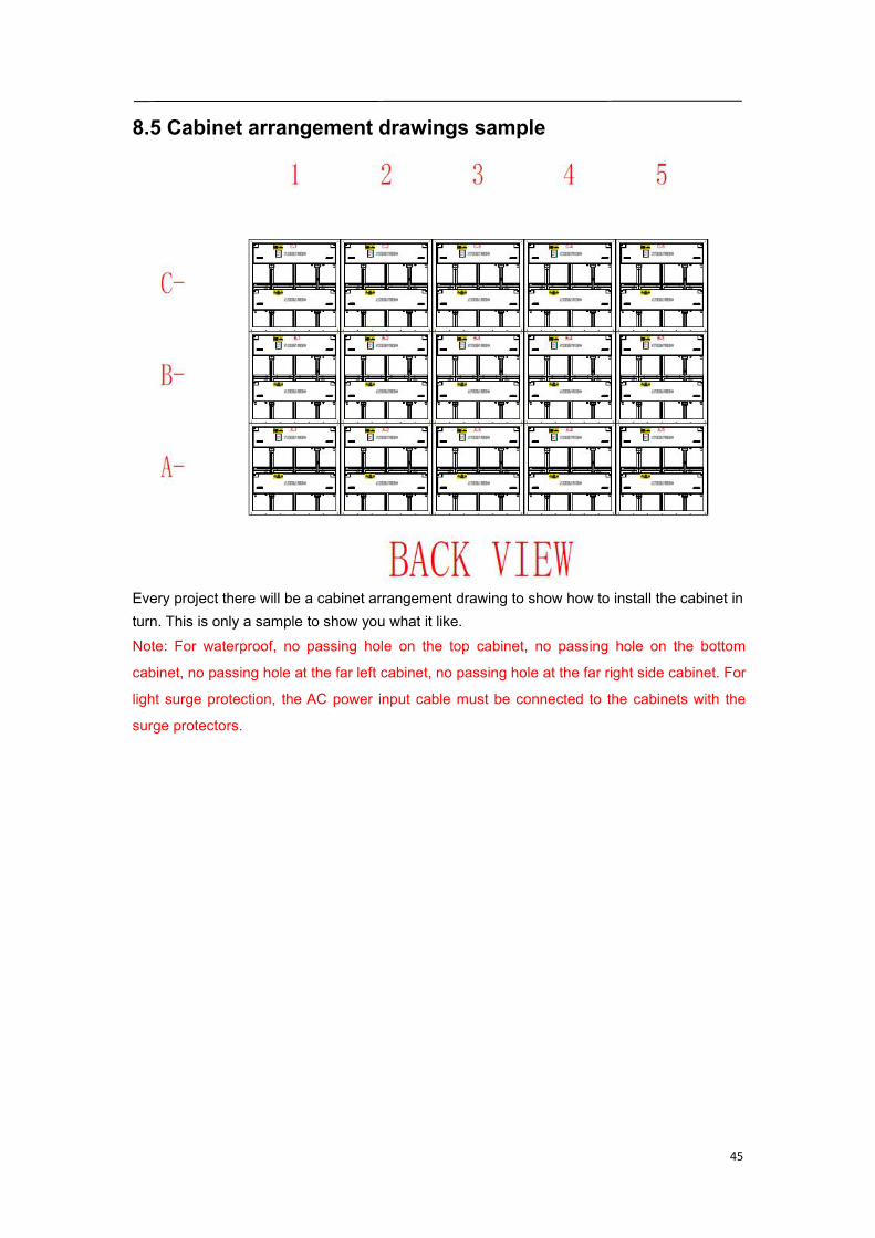
8.5 Cabinet arrangement drawings sample
Every project there will be a cabinet arrangement drawing to show how to install the cabinet inturn. This is only a sample to show you what it like.Note: For waterproof, no passing hole on the top cabinet, no passing hole on the bottom
cabinet, no passing hole at the far left cabinet, no passing hole at the far right side cabinet. For
light surge protection, the AC power input cable must be connected to the cabinets with the
surge protectors.
46
9. Control system setting
9.1 Software setup
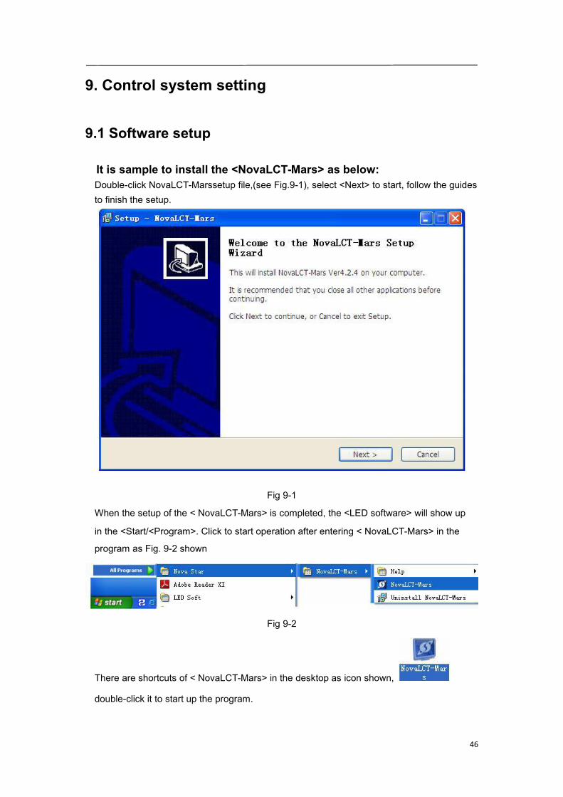
It is sample to install the <NovaLCT-Mars> as below:Double-click NovaLCT-Marssetup file,(see Fig.9-1), select <Next> to start, follow the guidesto finish the setup.
Fig 9-1
When the setup of the < NovaLCT-Mars> is completed, the <LED software> will show up
in the <Start/<Program>. Click to start operation after entering < NovaLCT-Mars> in the
program as Fig. 9-2 shown
Fig 9-2
There are shortcuts of < NovaLCT-Mars> in the desktop as icon shown,
double-click it to start up the program.

47
9.2 NovaLCT-Mars Main interface
This section describes how to use NovaLCT-Mars to set screenparameters as follows:Enter NovaLCT-Mars main interfaceStep 1:Start “NovaLCT-Mars", click ""User" → "Advanced Login", enter `User login`window as shown in Fig.9-3
Fig 9-3
Step 2:Input the password `admin`, enter the NovaLCT-Mars main interface for advancedusers as shown in Fig 9-4
Fig 9-4
48
9.3 Main Menu
SystemReconnect This is used to reconnecting the NovaLCT-Mars to the LED display control
system. SettingScreen ConfigOnly accessible by advanced users. This is used for configuration of the LED display controlsystem. Details about this operation will be given in a later part of this manual. BrightnessThis is used for adjusting the LED display brightness. There are two ways for brightnessadjustment, automatic brightness and manual brightness. Details about brightnessadjustment will be given in a later part of this manual.
Multi-function CardThis is used to open the page for multifunction card configuration. Details will be given in alater part of this manual.Multiple Screen ManagementOnly accessible by advanced users. This is used to open the page for combination displayconfiguration. It makes the management of brightness control and monitoring of multipleLED displays easier when these LED displays are combined together. Details will be givenin a later part of this manual.Hardware InformationThis is used to check the information about the current LED display control system.
Prestore ScreenEnter the restore screen, booting screen and no signal (including the disconnected networkcable and no DVI signal) screen settings can be conducted.Advanced color configurationFactory Setting (current gain, RGB brightness).Configuration color space (original color space ,target color space)Colortemperature table.My NovaiCareRegister the display screen to the user in NovaiCare.Module FlashView correction coefficients of the receiving card and module;Save correction coefficients in the receiving card and module;Test whether Flash is normal .Receiving card relaySet parameters for the receiving card relay;Reset the time of the receiving card.Configure information management(M)---Import/Export config.Set initial position---Set the initial coordinates.

49
ToolsCalibrationOnly accessible by advanced users. Select this item to open the calibration page. Detailsabout calibration will be given in a later part of this manual.Screen ControlBlack out--- Show nothing on the LED display.Lock --- Always show the current image frame of the LED display.Run--- Switch the LED display back to normal from Kill or Lock.Self Test --- show the test images generated by the receiver card for LED displays agingtest or error detecting.MonitorThis is used to open the page for system monitoring. Details will be given in a later part ofthis manual.Led Error DetectionThis is used to open the page for Led Error Detection (LED lights open/short circuit statuschecking).Multi-batch adjustmentAdjust the brightness of the display according to the batches of cabinet.Controller Cabinet Configuration File importAdd/Delete configuration files;Modify file name.Save the configuration file in controller.Quickly Adjust Dark or Bright linesAdjust dark or bright lines caused by box splicing, and recovery for cabinet.Video controlInput setting, output setting and stitching management of video processor.Plug-in ToolTest Tool --- To open the page which all test tools (test content) for LED displays testing are
in.Calculator --- A shortcut to the calculator application of Microsoft Windows. Click on thisitem will open the Microsoft Windows calculator.External Program ---a shortcut to add frequently used programs.UserAdvanced Login---This is for user login. The initial password for advanced users isadmin, after login , user can update the password.Enter Demonstration mode--- The password is “admin”, and user can experience a partof the function of LCT without connection to the hardware.
LanguageThis is used to switch the language of the NovaLCT-Mars application. Languages availablenow have ten languages.
HelpUser Documents---User Manual.Updating log---The description of function upgrading.About ---To check the version information about the NovaLCT-Mars application.

50
9.4 Tool Bar
--- the same as Tools->Screen Config in the main menu.
--- the same as Tools->Brightness in the main menu.
--- the same as Tools->Calibration in the main menu.
--- the same as Tools->Display Control in the main menu.
--- the same as Tools->Monitor in the main menu.
--- the same as Tools->Function Card in the main menu.
--- Register the display screen to the user in NovaiCare.
51
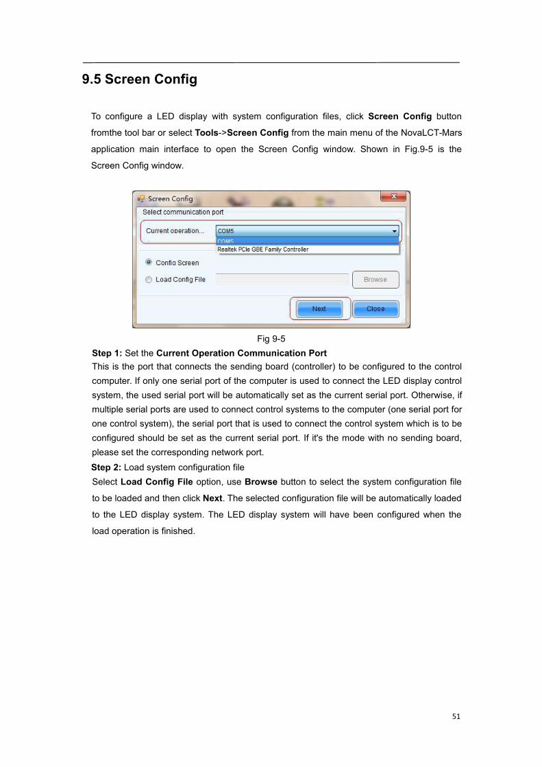
9.5 Screen Config
To configure a LED display with system configuration files, click Screen Config button
fromthe tool bar or select Tools->Screen Config from the main menu of the NovaLCT-Mars
application main interface to open the Screen Config window. Shown in Fig.9-5 is the
Screen Config window.
Fig 9-5Step 1: Set the Current Operation Communication PortThis is the port that connects the sending board (controller) to be configured to the controlcomputer. If only one serial port of the computer is used to connect the LED display controlsystem, the used serial port will be automatically set as the current serial port. Otherwise, ifmultiple serial ports are used to connect control systems to the computer (one serial port forone control system), the serial port that is used to connect the control system which is to beconfigured should be set as the current serial port. If it's the mode with no sending board,please set the corresponding network port.Step 2: Load system configuration fileSelect Load Config File option, use Browse button to select the system configuration file
to be loaded and then click Next. The selected configuration file will be automatically loaded
to the LED display system. The LED display system will have been configured when the
load operation is finished.
52
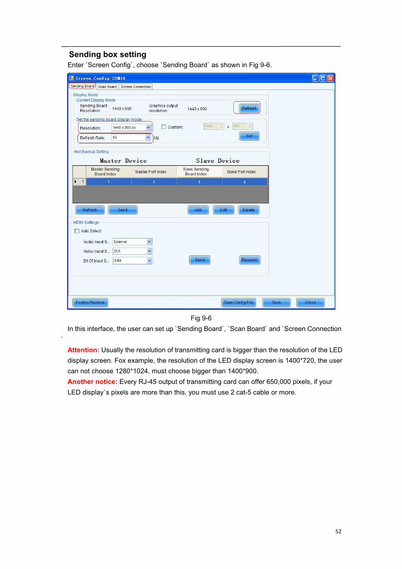
Sending box settingEnter `Screen Config`, choose `Sending Board` as shown in Fig 9-6.
Fig 9-6In this interface, the user can set up `Sending Board`, `Scan Board` and `Screen Connection
`Attention: Usually the resolution of transmitting card is bigger than the resolution of the LEDdisplay screen. Fox example, the resolution of the LED display screen is 1400*720, the usercan not choose 1280*1024, must choose bigger than 1400*900.Another notice: Every RJ-45 output of transmitting card can offer 650,000 pixels, if yourLED display`s pixels are more than this, you must use 2 cat-5 cable or more.
53
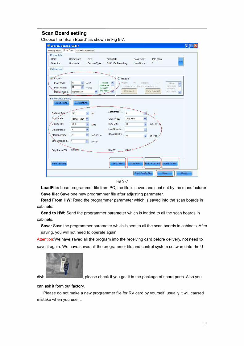
Scan Board settingChoose the `Scan Board` as shown in Fig 9-7.
Fig 9-7LoadFile: Load programmer file from PC, the file is saved and sent out by the manufacturer.Save file: Save one new programmer file after adjusting parameter.Read From HW: Read the programmer parameter which is saved into the scan boards in
cabinets.Send to HW: Send the programmer parameter which is loaded to all the scan boards in
cabinets.Save: Save the programmer parameter which is sent to all the scan boards in cabinets. Aftersaving, you will not need to operate again.
Attention:We have saved all the program into the receiving card before delivery, not need to
save it again. We have saved all the programmer file and control system software into the U
disk , please check if you got it in the package of spare parts. Also you
can ask it form out factory.Please do not make a new programmer file for RV card by yourself, usually it will caused
mistake when you use it.
54
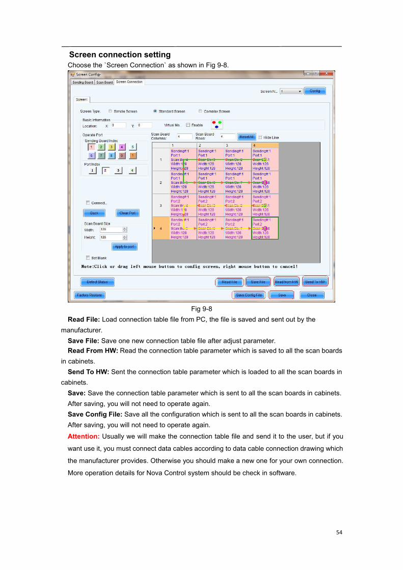
Screen connection settingChoose the `Screen Connection` as shown in Fig 9-8.
Fig 9-8Read File: Load connection table file from PC, the file is saved and sent out by the
manufacturer.Save File: Save one new connection table file after adjust parameter.Read From HW: Read the connection table parameter which is saved to all the scan boards
in cabinets.Send To HW: Sent the connection table parameter which is loaded to all the scan boards in
cabinets.Save: Save the connection table parameter which is sent to all the scan boards in cabinets.After saving, you will not need to operate again.Save Config File: Save all the configuration which is sent to all the scan boards in cabinets.After saving, you will not need to operate again.Attention: Usually we will make the connection table file and send it to the user, but if you
want use it, you must connect data cables according to data cable connection drawing which
the manufacturer provides. Otherwise you should make a new one for your own connection.
More operation details for Nova Control system should be check in software.

55
9.6 Advanced color configuration
Advanced color configuration includes the exit-factory configuration, color space
configuration and color temperature table configuration, the target color space plan and
color temperature table configured here can be called directed when adjusting brightness.

56
Factory SettingCurrent Gain:some chips support current gain control;
:Default Value: click to restore the default values.
RGB Brightness : adjusts brightness of R/G/B colors respectively , or check“synchronization” to adjust the three colors synchronously;
: Save the current gain and brightness to hardware;
: Import local color configuration file;
: Export current color configuration and save on local disk.1) Color space configuration
Original color space : It is suggested to use a light gun to measure current CIEcoordinates and brightness and fill out properly, use original color space as basis foradjusting color temperature.Target color space:The black triangle in the color space on left side of the interface istarget color space, drag your mouse to change four-color target pixel.It’s also allowed to directly change all coefficients of the target color space, when adjusting
the target color space, preview the adjustment results on the LED screen until satisfaction.
57
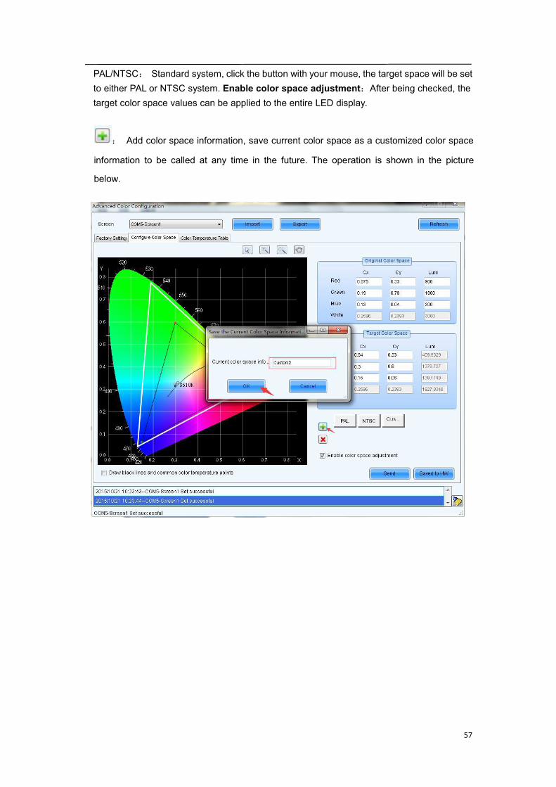
PAL/NTSC: Standard system, click the button with your mouse, the target space will be setto either PAL or NTSC system. Enable color space adjustment:After being checked, thetarget color space values can be applied to the entire LED display.
: Add color space information, save current color space as a customized color space
information to be called at any time in the future. The operation is shown in the picture
below.
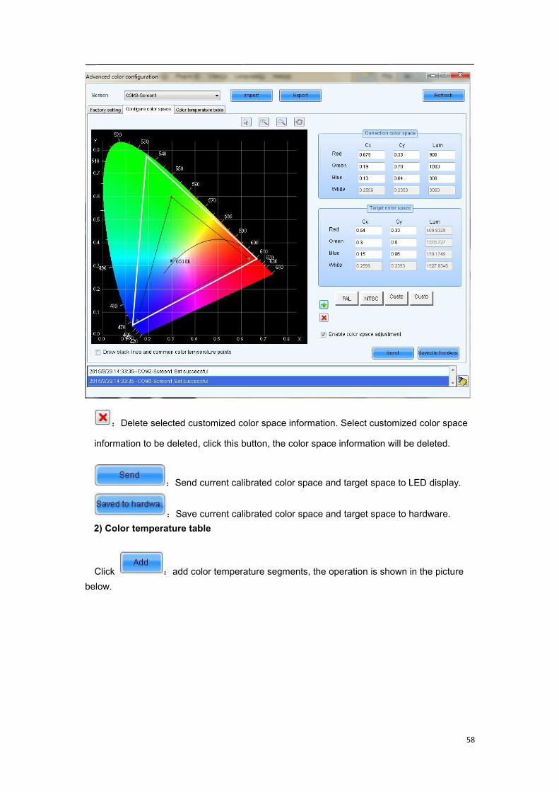
58
:Delete selected customized color space information. Select customized color space
information to be deleted, click this button, the color space information will be deleted.
:Send current calibrated color space and target space to LED display.
:Save current calibrated color space and target space to hardware.2) Color temperature table
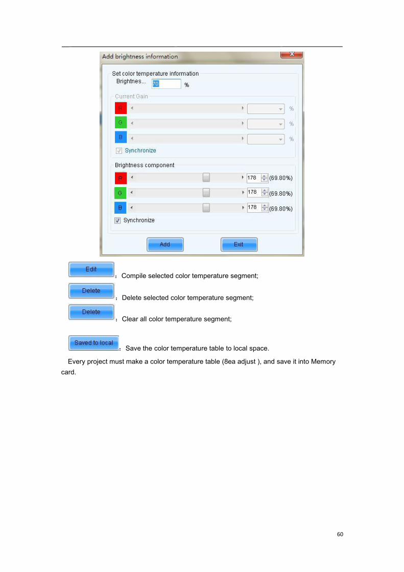
Click :add color temperature segments, the operation is shown in the picturebelow.

59
60
:Compile selected color temperature segment;
:Delete selected color temperature segment;
:Clear all color temperature segment;
:Save the color temperature table to local space.
Every project must make a color temperature table (8ea adjust ), and save it into Memorycard.
61
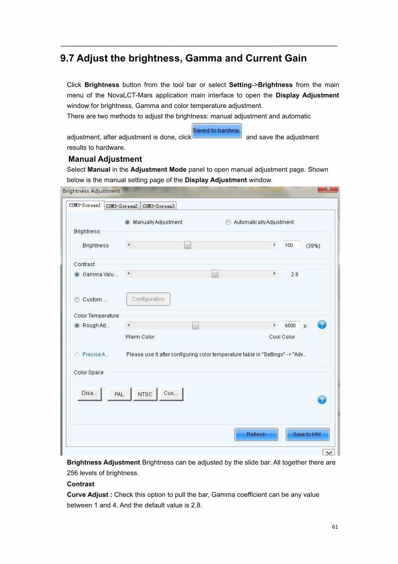
9.7 Adjust the brightness, Gamma and Current Gain
Click Brightness button from the tool bar or select Setting->Brightness from the mainmenu of the NovaLCT-Mars application main interface to open the Display Adjustmentwindow for brightness, Gamma and color temperature adjustment.There are two methods to adjust the brightness: manual adjustment and automatic
adjustment, after adjustment is done, click and save the adjustmentresults to hardware.
Manual AdjustmentSelect Manual in the Adjustment Mode panel to open manual adjustment page. Shownbelow is the manual setting page of the Display Adjustment window.
Brightness Adjustment Brightness can be adjusted by the slide bar. All together there are256 levels of brightness.ContrastCurve Adjust : Check this option to pull the bar, Gamma coefficient can be any valuebetween 1 and 4. And the default value is 2.8.
62
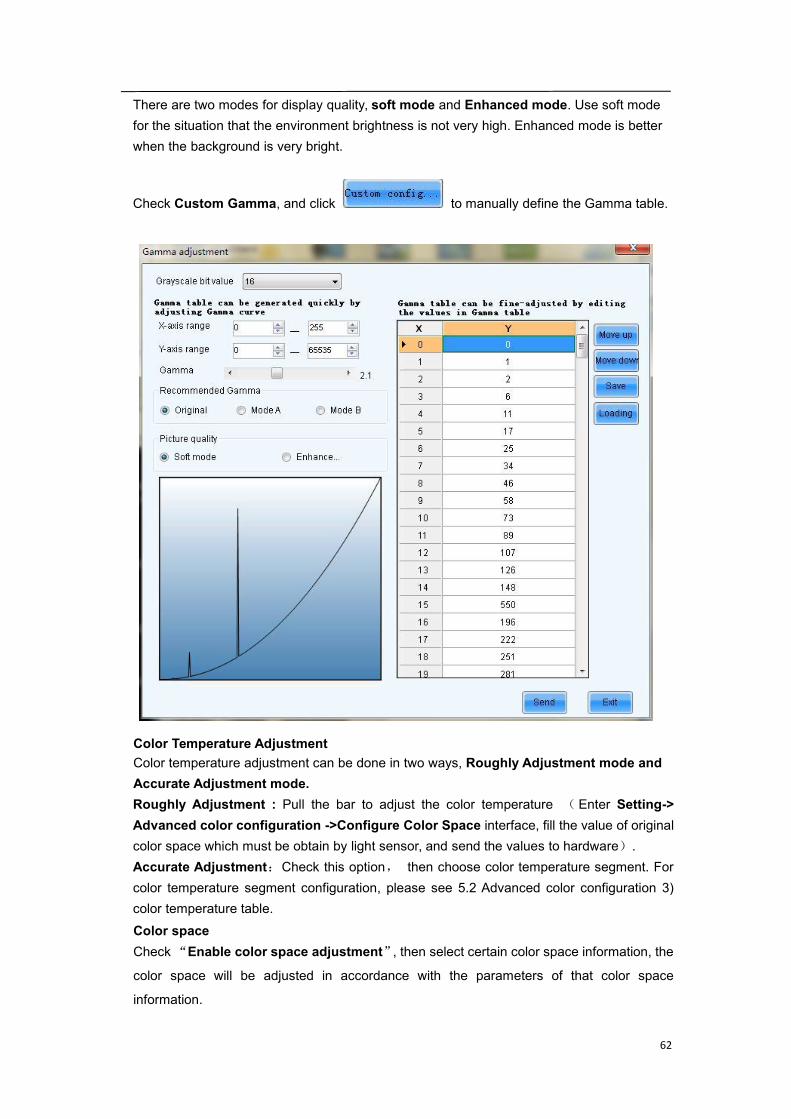
There are two modes for display quality, soft mode and Enhanced mode. Use soft modefor the situation that the environment brightness is not very high. Enhanced mode is betterwhen the background is very bright.
Check Custom Gamma, and click to manually define the Gamma table.
Color Temperature AdjustmentColor temperature adjustment can be done in two ways, Roughly Adjustment mode andAccurate Adjustment mode.Roughly Adjustment : Pull the bar to adjust the color temperature ( Enter Setting->Advanced color configuration ->Configure Color Space interface, fill the value of originalcolor space which must be obtain by light sensor, and send the values to hardware).Accurate Adjustment:Check this option, then choose color temperature segment. Forcolor temperature segment configuration, please see 5.2 Advanced color configuration 3)color temperature table.Color spaceCheck“Enable color space adjustment”, then select certain color space information, the
color space will be adjusted in accordance with the parameters of that color space
information.
63
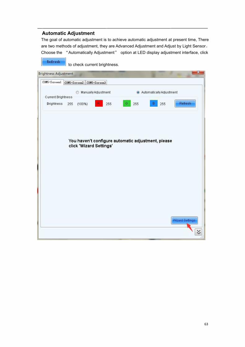
Automatic AdjustmentThe goal of automatic adjustment is to achieve automatic adjustment at present time, Thereare two methods of adjustment, they are Advanced Adjustment and Adjust by Light Sensor。Choose the “Automatically Adjustment” option at LED display adjustment interface, click
to check current brightness.
64
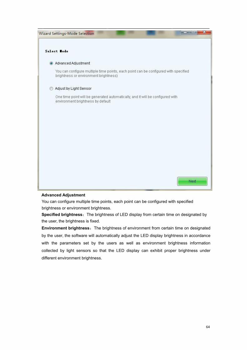
Advanced AdjustmentYou can configure multiple time points, each point can be configured with specifiedbrightness or environment brightness.Specified brightness:The brightness of LED display from certain time on designated bythe user, the brightness is fixed.Environment brightness:The brightness of environment from certain time on designated
by the user, the software will automatically adjust the LED display brightness in accordance
with the parameters set by the users as well as environment brightness information
collected by light sensors so that the LED display can exhibit proper brightness under
different environment brightness.
65
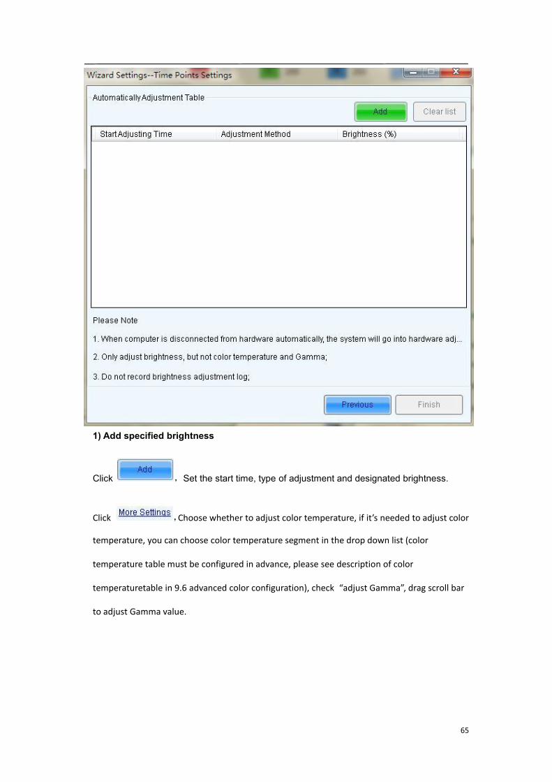
1) Add specified brightness
Click ,Set the start time, type of adjustment and designated brightness.
Click ,Choose whether to adjust color temperature, if it’s needed to adjust color
temperature, you can choose color temperature segment in the drop down list (color
temperature table must be configured in advance, please see description of color
temperaturetable in 9.6 advanced color configuration), check “adjust Gamma”, drag scroll bar
to adjust Gamma value.
66
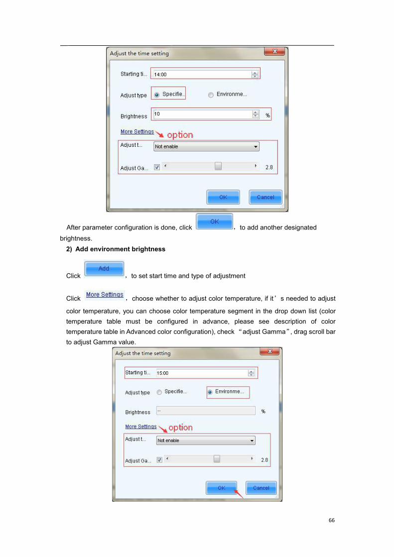
After parameter configuration is done, click ,to add another designatedbrightness.2) Add environment brightness
Click ,to set start time and type of adjustment
Click ,choose whether to adjust color temperature, if it’s needed to adjust
color temperature, you can choose color temperature segment in the drop down list (colortemperature table must be configured in advance, please see description of colortemperature table in Advanced color configuration), check“adjust Gamma”, drag scroll barto adjust Gamma value.
67
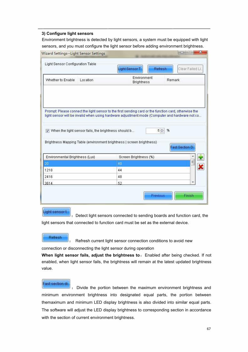
3) Configure light sensorsEnvironment brightness is detected by light sensors, a system must be equipped with lightsensors, and you must configure the light sensor before adding environment brightness.
:Detect light sensors connected to sending boards and function card, the
light sensors that connected to function card must be set as the external device.
: Refresh current light sensor connection conditions to avoid new
connection or disconnecting the light sensor during operationWhen light sensor fails, adjust the brightness to:Enabled after being checked. If notenabled, when light sensor fails, the brightness will remain at the latest updated brightnessvalue.
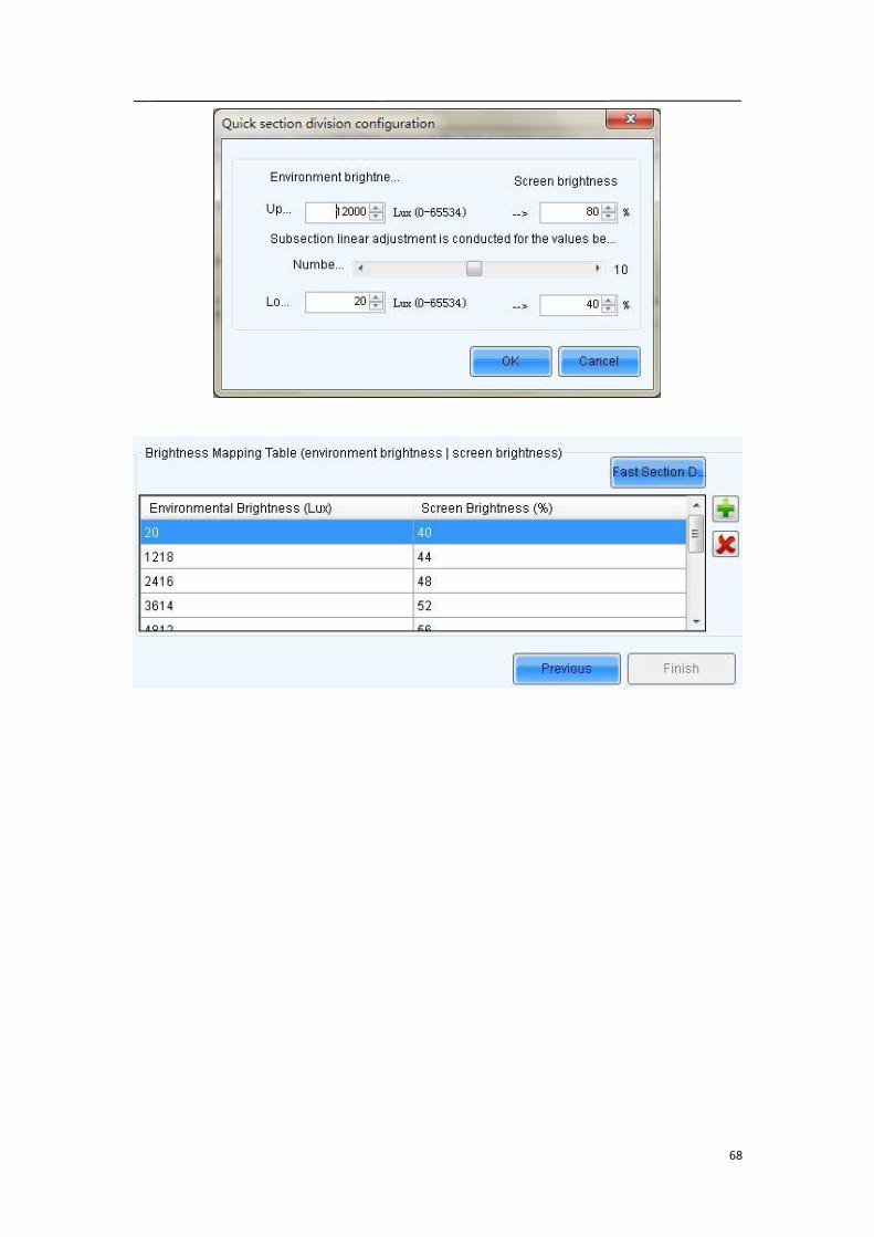
:Divide the portion between the maximum environment brightness and
minimum environment brightness into designated equal parts, the portion between
themaximum and minimum LED display brightness is also divided into similar equal parts.
The software will adjust the LED display brightness to corresponding section in accordance
with the section of current environment brightness.
68
69
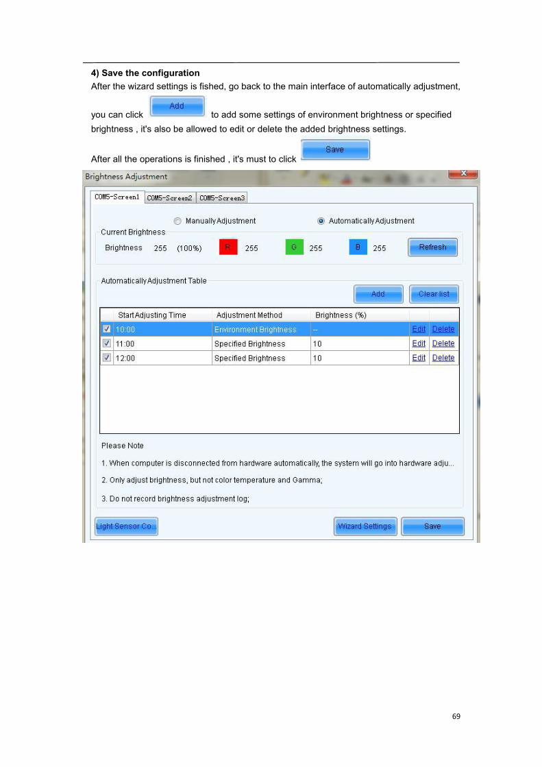
4) Save the configurationAfter the wizard settings is fished, go back to the main interface of automatically adjustment,
you can click to add some settings of environment brightness or specifiedbrightness , it's also be allowed to edit or delete the added brightness settings.
After all the operations is finished , it's must to click

70
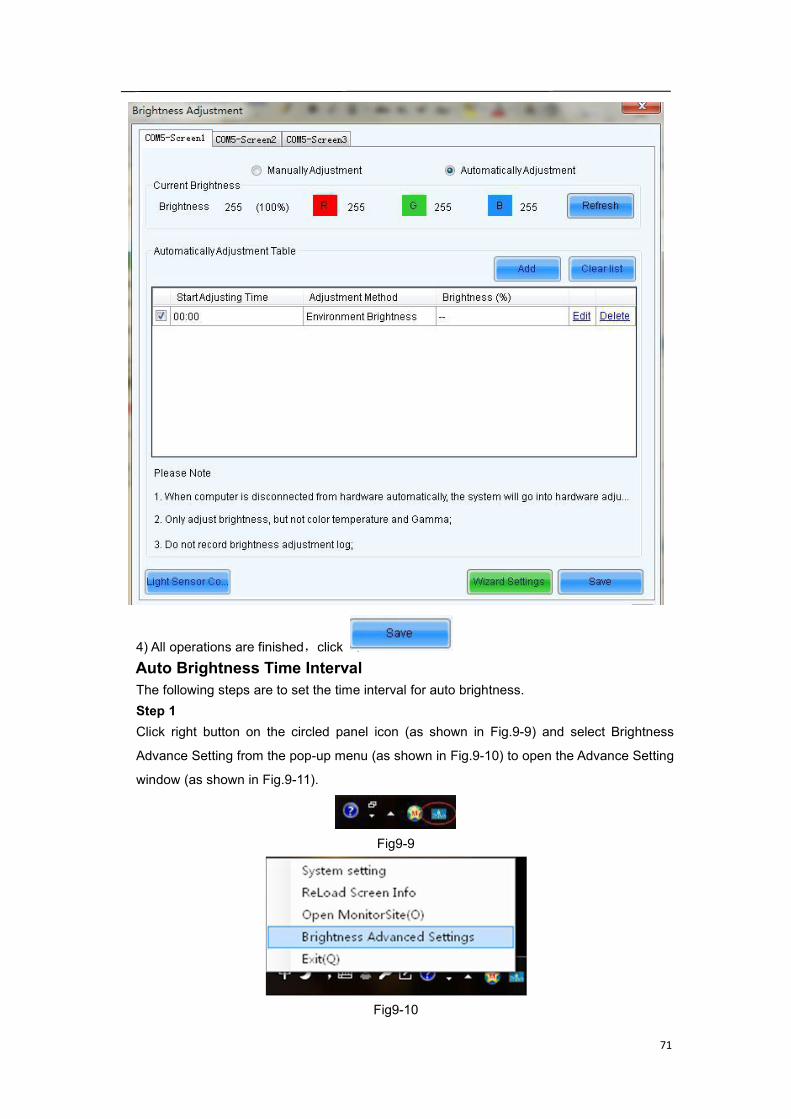
Adjust by Light SensorOne time point will be generated by LCT automatically, and it will be configured withenvironment brightness by default.
1) Click ,check “Adjust by Light Sensor”,then click
.
2) If you have not finished configuration of light sensor, it's need to configure the light sensorthen, the detailed operation, please refer to the step 3) in 5.3.2.1 advanced adjustment.3) The environment brightness by Software added automatically as shown in the figure
below, according to your need to add specified brightness or environment brightness, or to
edit or delete the added Settings.
71
4) All operations are finished,click .Auto Brightness Time IntervalThe following steps are to set the time interval for auto brightness.Step 1Click right button on the circled panel icon (as shown in Fig.9-9) and select Brightness
Advance Setting from the pop-up menu (as shown in Fig.9-10) to open the Advance Setting
window (as shown in Fig.9-11).
Fig9-9
Fig9-10
72
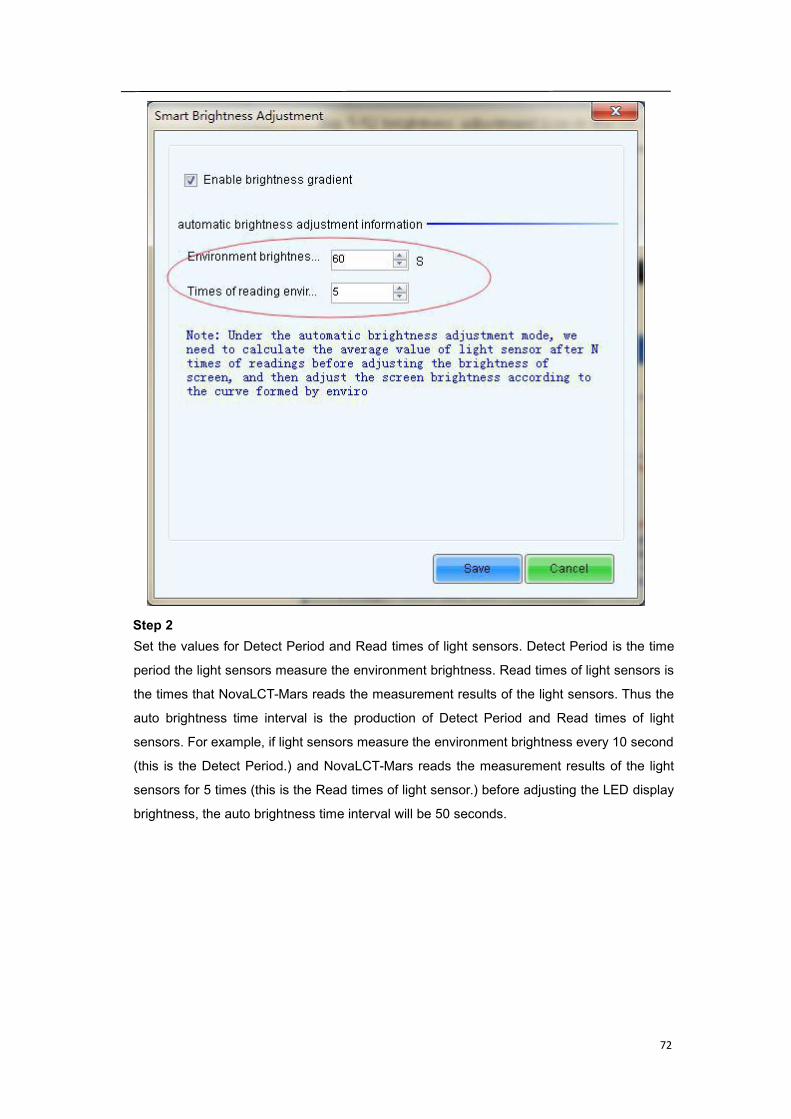
Step 2Set the values for Detect Period and Read times of light sensors. Detect Period is the time
period the light sensors measure the environment brightness. Read times of light sensors is
the times that NovaLCT-Mars reads the measurement results of the light sensors. Thus the
auto brightness time interval is the production of Detect Period and Read times of light
sensors. For example, if light sensors measure the environment brightness every 10 second
(this is the Detect Period.) and NovaLCT-Mars reads the measurement results of the light
sensors for 5 times (this is the Read times of light sensor.) before adjusting the LED display
brightness, the auto brightness time interval will be 50 seconds.
73
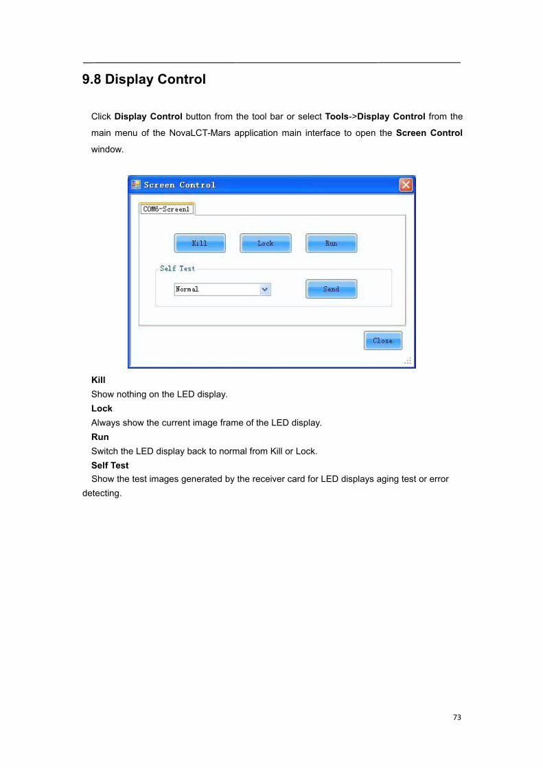
9.8 Display Control
Click Display Control button from the tool bar or select Tools->Display Control from the
main menu of the NovaLCT-Mars application main interface to open the Screen Control
window.
KillShow nothing on the LED display.LockAlways show the current image frame of the LED display.RunSwitch the LED display back to normal from Kill or Lock.Self TestShow the test images generated by the receiver card for LED displays aging test or error
detecting.
74
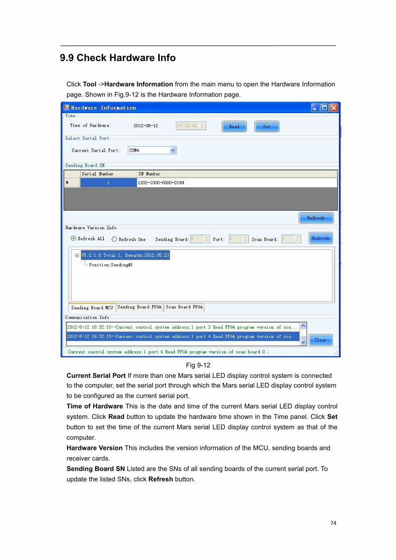
9.9 Check Hardware Info
Click Tool ->Hardware Information from the main menu to open the Hardware Informationpage. Shown in Fig.9-12 is the Hardware Information page.
Fig 9-12Current Serial Port If more than one Mars serial LED display control system is connectedto the computer, set the serial port through which the Mars serial LED display control systemto be configured as the current serial port.Time of Hardware This is the date and time of the current Mars serial LED display controlsystem. Click Read button to update the hardware time shown in the Time panel. Click Setbutton to set the time of the current Mars serial LED display control system as that of thecomputer.Hardware Version This includes the version information of the MCU, sending boards andreceiver cards.Sending Board SN Listed are the SNs of all sending boards of the current serial port. Toupdate the listed SNs, click Refresh button.
75
9.10 Brightness/Color Calibration
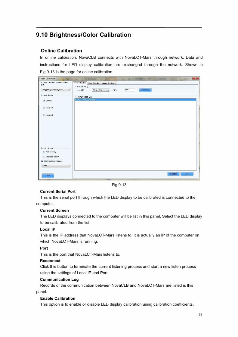
Online CalibrationIn online calibration, NovaCLB connects with NovaLCT-Mars through network. Data and
instructions for LED display calibration are exchanged through the network. Shown in
Fig.9-13 is the page for online calibration.
Fig 9-13Current Serial PortThis is the serial port through which the LED display to be calibrated is connected to the
computer.Current ScreenThe LED displays connected to the computer will be list in this panel. Select the LED displayto be calibrated from the list.Local IPThis is the IP address that NovaLCT-Mars listens to. It is actually an IP of the computer onwhich NovaLCT-Mars is running.PortThis is the port that NovaLCT-Mars listens to.ReconnectClick this button to terminate the current listening process and start a new listen processusing the settings of Local IP and Port.Communication LogRecords of the communication between NovaCLB and NovaLCT-Mars are listed is this
panel.Enable CalibrationThis option is to enable or disable LED display calibration using calibration coefficients.
76
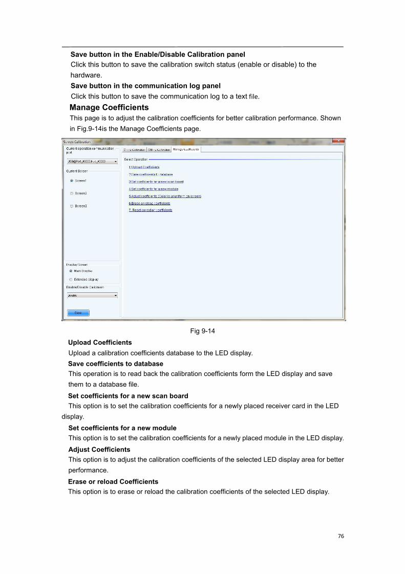
Save button in the Enable/Disable Calibration panelClick this button to save the calibration switch status (enable or disable) to thehardware.Save button in the communication log panelClick this button to save the communication log to a text file.Manage CoefficientsThis page is to adjust the calibration coefficients for better calibration performance. Shownin Fig.9-14is the Manage Coefficients page.
Fig 9-14Upload CoefficientsUpload a calibration coefficients database to the LED display.Save coefficients to databaseThis operation is to read back the calibration coefficients form the LED display and savethem to a database file.Set coefficients for a new scan boardThis option is to set the calibration coefficients for a newly placed receiver card in the LED
display.Set coefficients for a new moduleThis option is to set the calibration coefficients for a newly placed module in the LED display.Adjust CoefficientsThis option is to adjust the calibration coefficients of the selected LED display area for betterperformance.Erase or reload CoefficientsThis option is to erase or reload the calibration coefficients of the selected LED display.
77
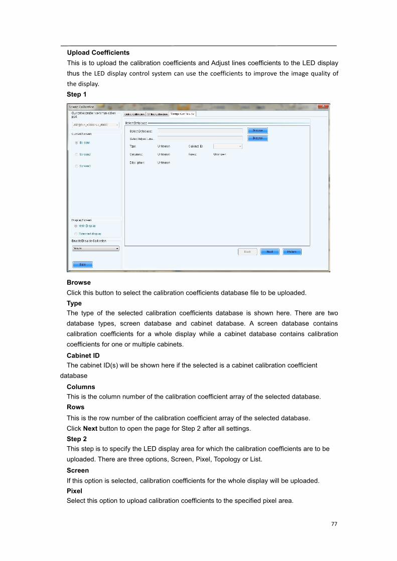
Upload CoefficientsThis is to upload the calibration coefficients and Adjust lines coefficients to the LED displaythus the LED display control system can use the coefficients to improve the image quality ofthe display.Step 1
BrowseClick this button to select the calibration coefficients database file to be uploaded.TypeThe type of the selected calibration coefficients database is shown here. There are twodatabase types, screen database and cabinet database. A screen database containscalibration coefficients for a whole display while a cabinet database contains calibrationcoefficients for one or multiple cabinets.Cabinet IDThe cabinet ID(s) will be shown here if the selected is a cabinet calibration coefficient
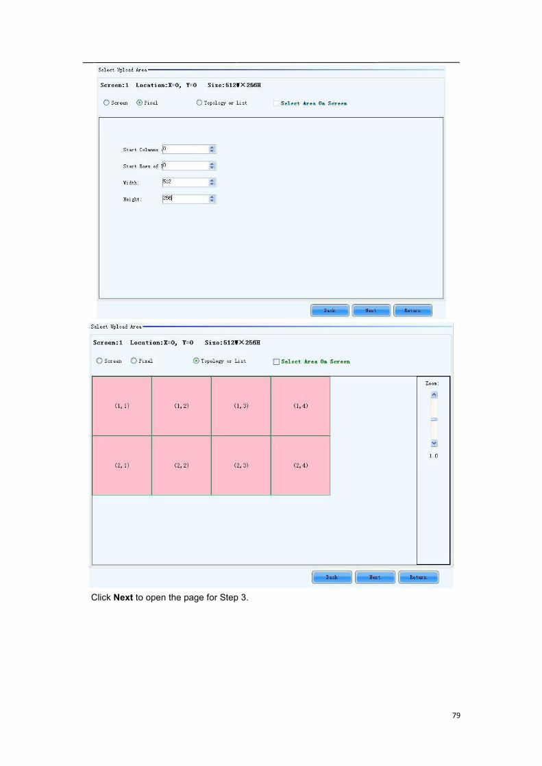
databaseColumnsThis is the column number of the calibration coefficient array of the selected database.RowsThis is the row number of the calibration coefficient array of the selected database.Click Next button to open the page for Step 2 after all settings.Step 2This step is to specify the LED display area for which the calibration coefficients are to beuploaded. There are three options, Screen, Pixel, Topology or List.ScreenIf this option is selected, calibration coefficients for the whole display will be uploaded.PixelSelect this option to upload calibration coefficients to the specified pixel area.
78
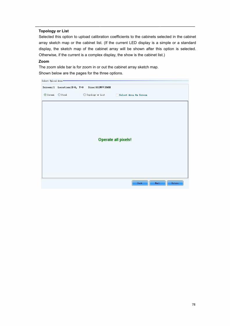
Topology or ListSelected this option to upload calibration coefficients to the cabinets selected in the cabinetarray sketch map or the cabinet list. (If the current LED display is a simple or a standarddisplay, the sketch map of the cabinet array will be shown after this option is selected.Otherwise, if the current is a complex display, the show is the cabinet list.)ZoomThe zoom slide bar is for zoom in or out the cabinet array sketch map.Shown below are the pages for the three options.
79
Click Next to open the page for Step 3.
80
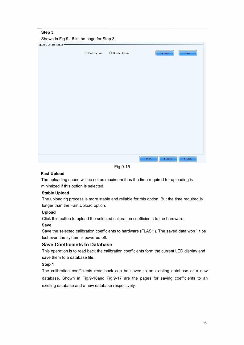
Step 3Shown in Fig.9-15 is the page for Step 3.
Fig 9-15Fast UploadThe uploading speed will be set as maximum thus the time required for uploading isminimized if this option is selected.Stable UploadThe uploading process is more stable and reliable for this option. But the time required islonger than the Fast Upload option.UploadClick this button to upload the selected calibration coefficients to the hardware.SaveSave the selected calibration coefficients to hardware (FLASH). The saved data won’t belost even the system is powered off.
Save Coefficients to DatabaseThis operation is to read back the calibration coefficients form the current LED display andsave them to a database file.Step 1The calibration coefficients read back can be saved to an existing database or a new
database. Shown in Fig.9-16and Fig.9-17 are the pages for saving coefficients to an
existing database and a new database respectively.
81
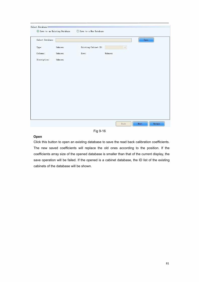
Fig 9-16OpenClick this button to open an existing database to save the read back calibration coefficients.
The new saved coefficients will replace the old ones according to the position. If the
coefficients array size of the opened database is smaller than that of the current display, the
save operation will be failed. If the opened is a cabinet database, the ID list of the existing
cabinets of the database will be shown.
82
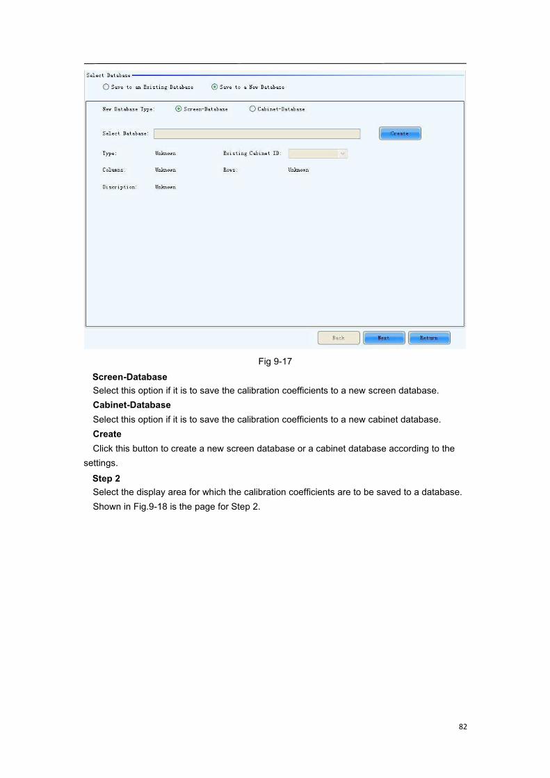
Fig 9-17Screen-DatabaseSelect this option if it is to save the calibration coefficients to a new screen database.Cabinet-DatabaseSelect this option if it is to save the calibration coefficients to a new cabinet database.CreateClick this button to create a new screen database or a cabinet database according to the
settings.Step 2Select the display area for which the calibration coefficients are to be saved to a database.Shown in Fig.9-18 is the page for Step 2.
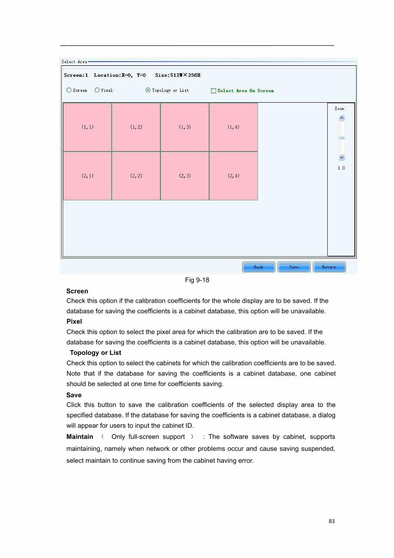
83
Fig 9-18ScreenCheck this option if the calibration coefficients for the whole display are to be saved. If thedatabase for saving the coefficients is a cabinet database, this option will be unavailable.PixelCheck this option to select the pixel area for which the calibration are to be saved. If thedatabase for saving the coefficients is a cabinet database, this option will be unavailable.Topology or ListCheck this option to select the cabinets for which the calibration coefficients are to be saved.Note that if the database for saving the coefficients is a cabinet database, one cabinetshould be selected at one time for coefficients saving.SaveClick this button to save the calibration coefficients of the selected display area to thespecified database. If the database for saving the coefficients is a cabinet database, a dialogwill appear for users to input the cabinet ID.Maintain ( Only full-screen support ) : The software saves by cabinet, supports
maintaining, namely when network or other problems occur and cause saving suspended,
select maintain to continue saving from the cabinet having error.
84
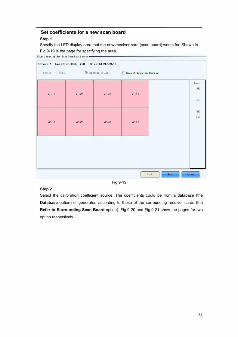
Set coefficients for a new scan boardStep 1Specify the LED display area that the new receiver card (scan board) works for. Shown inFig.9-19 is the page for specifying the area.
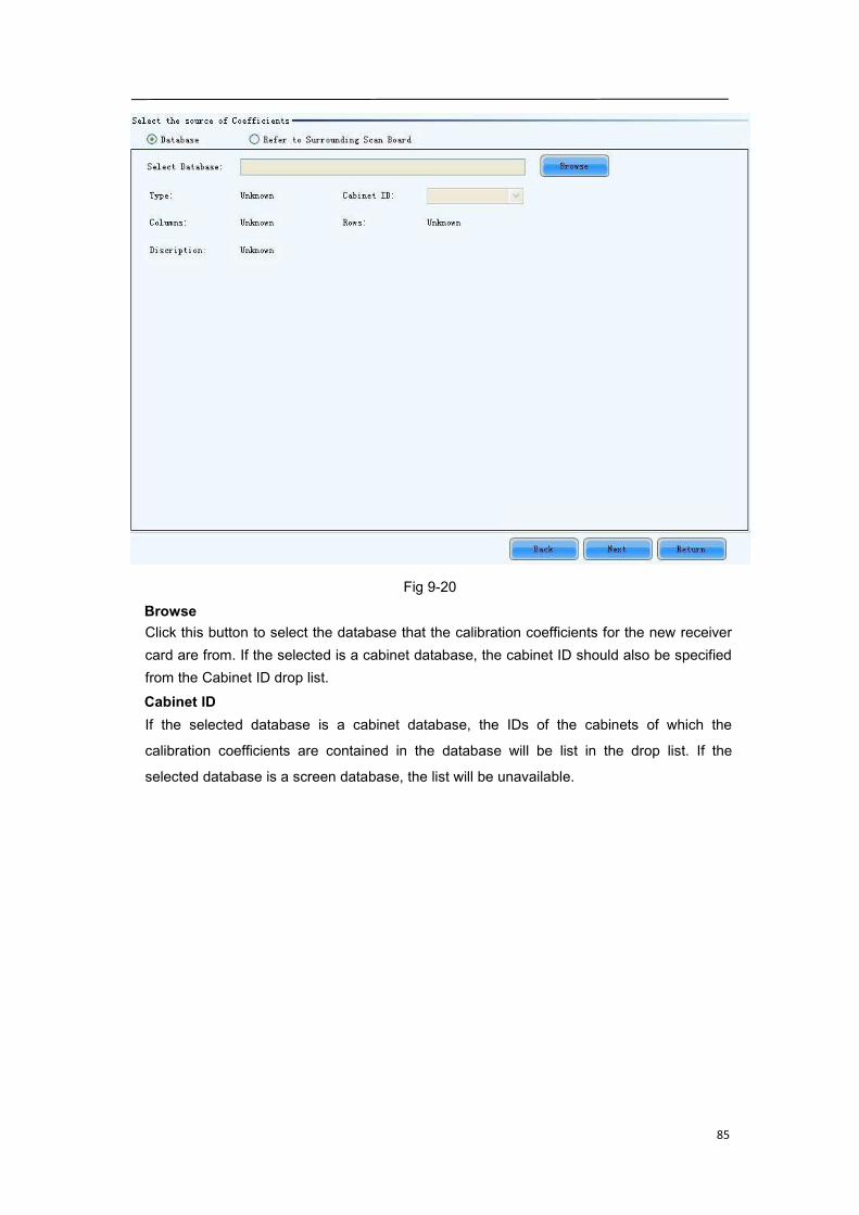
Fig 9-19Step 2Select the calibration coefficient source. The coefficients could be from a database (the
Database option) or generated according to those of the surrounding receiver cards (the
Refer to Surrounding Scan Board option). Fig.9-20 and Fig.9-21 show the pages for two
option respectively.
85
Fig 9-20BrowseClick this button to select the database that the calibration coefficients for the new receivercard are from. If the selected is a cabinet database, the cabinet ID should also be specifiedfrom the Cabinet ID drop list.Cabinet IDIf the selected database is a cabinet database, the IDs of the cabinets of which the
calibration coefficients are contained in the database will be list in the drop list. If the
selected database is a screen database, the list will be unavailable.
86
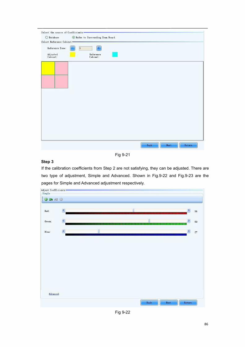
Fig 9-21Step 3If the calibration coefficients from Step 2 are not satisfying, they can be adjusted. There are
two type of adjustment, Simple and Advanced. Shown in Fig.9-22 and Fig.9-23 are the
pages for Simple and Advanced adjustment respectively.
Fig 9-22
87
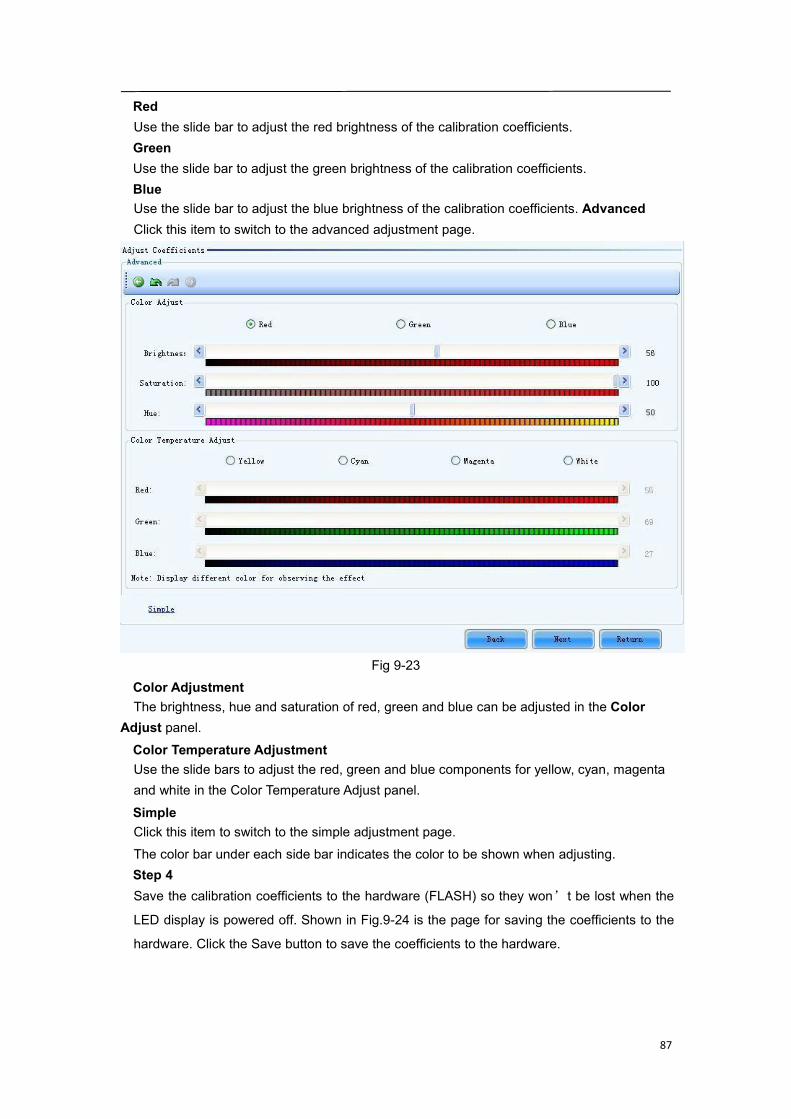
RedUse the slide bar to adjust the red brightness of the calibration coefficients.GreenUse the slide bar to adjust the green brightness of the calibration coefficients.BlueUse the slide bar to adjust the blue brightness of the calibration coefficients. AdvancedClick this item to switch to the advanced adjustment page.
Fig 9-23Color AdjustmentThe brightness, hue and saturation of red, green and blue can be adjusted in the Color
Adjust panel.Color Temperature AdjustmentUse the slide bars to adjust the red, green and blue components for yellow, cyan, magentaand white in the Color Temperature Adjust panel.SimpleClick this item to switch to the simple adjustment page.The color bar under each side bar indicates the color to be shown when adjusting.Step 4Save the calibration coefficients to the hardware (FLASH) so they won’t be lost when the
LED display is powered off. Shown in Fig.9-24 is the page for saving the coefficients to the
hardware. Click the Save button to save the coefficients to the hardware.
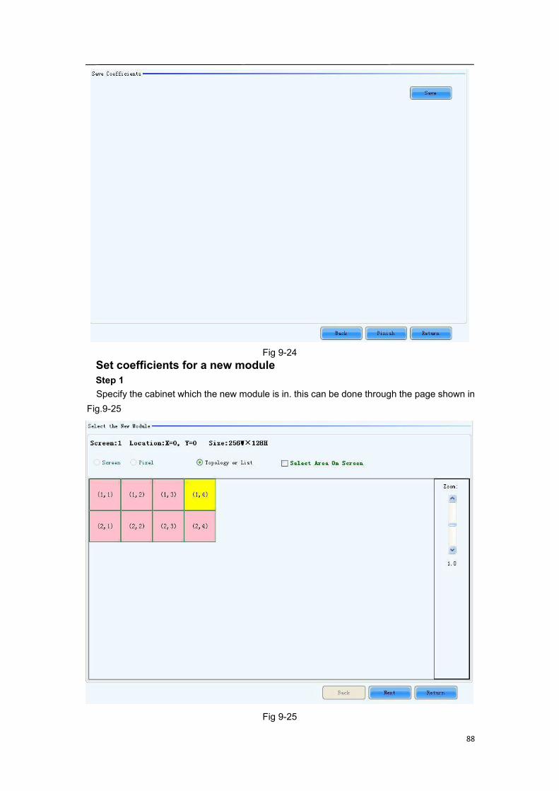
88
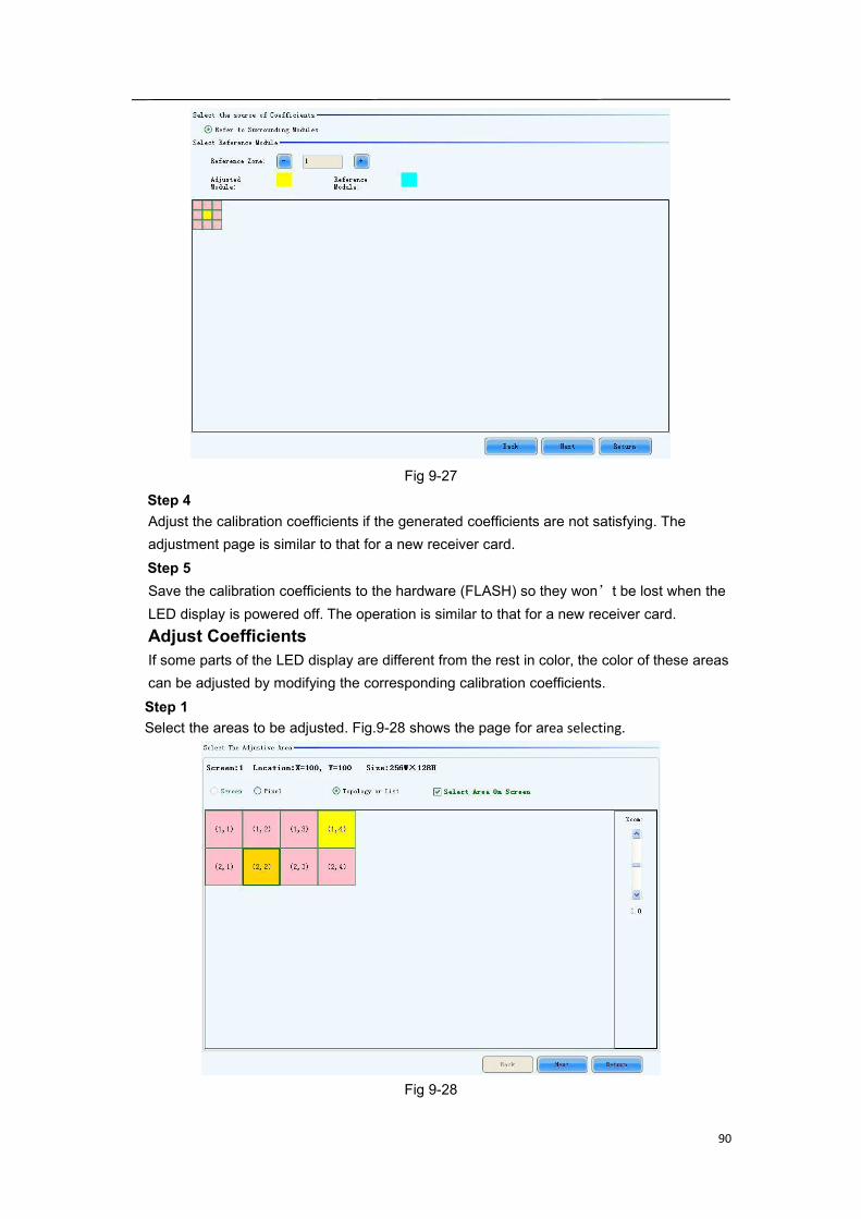
Fig 9-24Set coefficients for a new moduleStep 1Specify the cabinet which the new module is in. this can be done through the page shown in
Fig.9-25
Fig 9-25

89
Step 2Double click the selected cabinet to open the page for specifying the new module. Shown inFig.9-26 is the page for specifying the new module.
Fig 9-26Module SizeSet the pixel array size of a module here. NovaLCT-Mars divides a cabinet into modulesaccording to the module pixel array size and the cabinet pixel array size.Step 3Select the calibration coefficients source. Calibration coefficients generated according to
those of the surrounding modules are used for the new module because the coefficients
saved in the receiver card or the database are not suitable for the new module. Shown in
Fig.9-27 is the page for selecting the coefficients source.
90
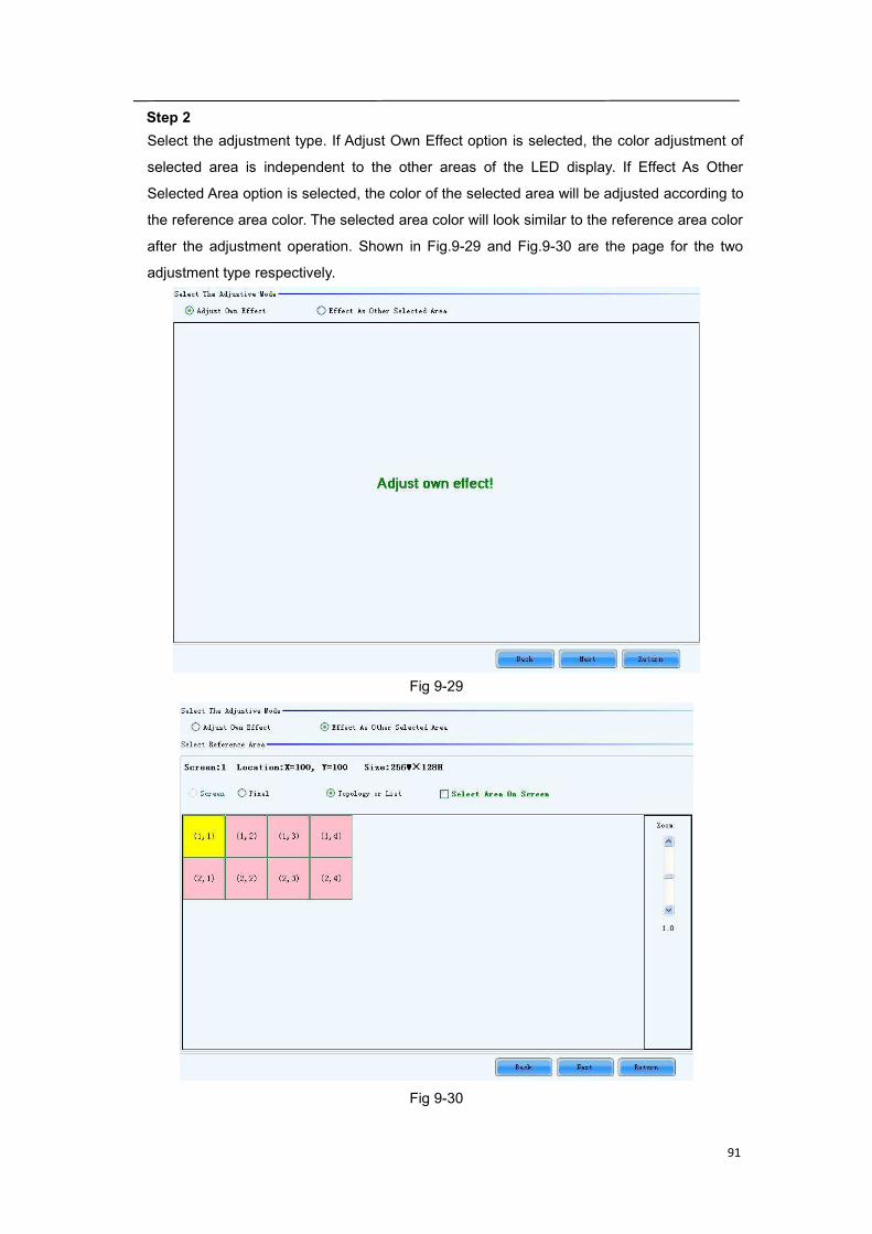
Fig 9-27Step 4Adjust the calibration coefficients if the generated coefficients are not satisfying. Theadjustment page is similar to that for a new receiver card.Step 5Save the calibration coefficients to the hardware (FLASH) so they won’t be lost when theLED display is powered off. The operation is similar to that for a new receiver card.Adjust CoefficientsIf some parts of the LED display are different from the rest in color, the color of these areascan be adjusted by modifying the corresponding calibration coefficients.Step 1Select the areas to be adjusted. Fig.9-28 shows the page for area selecting.
Fig 9-28
91
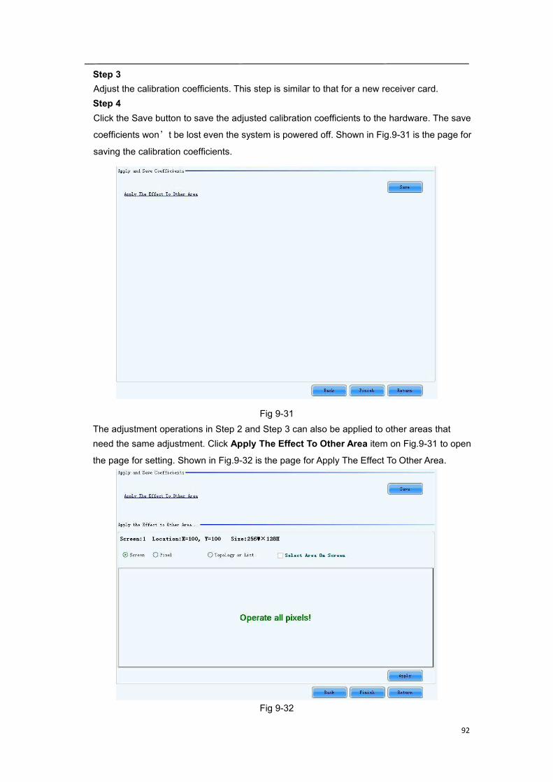
Step 2Select the adjustment type. If Adjust Own Effect option is selected, the color adjustment of
selected area is independent to the other areas of the LED display. If Effect As Other
Selected Area option is selected, the color of the selected area will be adjusted according to
the reference area color. The selected area color will look similar to the reference area color
after the adjustment operation. Shown in Fig.9-29 and Fig.9-30 are the page for the two
adjustment type respectively.
Fig 9-29
Fig 9-30
92
Step 3Adjust the calibration coefficients. This step is similar to that for a new receiver card.Step 4Click the Save button to save the adjusted calibration coefficients to the hardware. The save
coefficients won’t be lost even the system is powered off. Shown in Fig.9-31 is the page for
saving the calibration coefficients.
Fig 9-31The adjustment operations in Step 2 and Step 3 can also be applied to other areas thatneed the same adjustment. Click Apply The Effect To Other Area item on Fig.9-31 to open
the page for setting. Shown in Fig.9-32 is the page for Apply The Effect To Other Area.
Fig 9-32

93
ApplyApply adjustment operations to the selected area.Erase or reload CoefficientsShown in Fig.9-33 is the page for erasing/reload calibration coefficients.Erase coefficients: erasing calibration coefficients of the whole display or any cabinets.Reload coefficients: reload the calibration coefficients lastly saved in hardware.
Fig 9-33ScreenSelect this option to erase all calibration coefficients for the whole display.Topology or ListSelect this option to select the cabinets from the cabinet array sketch or the cabinet list ofwhich the calibration coefficients are to be erased.
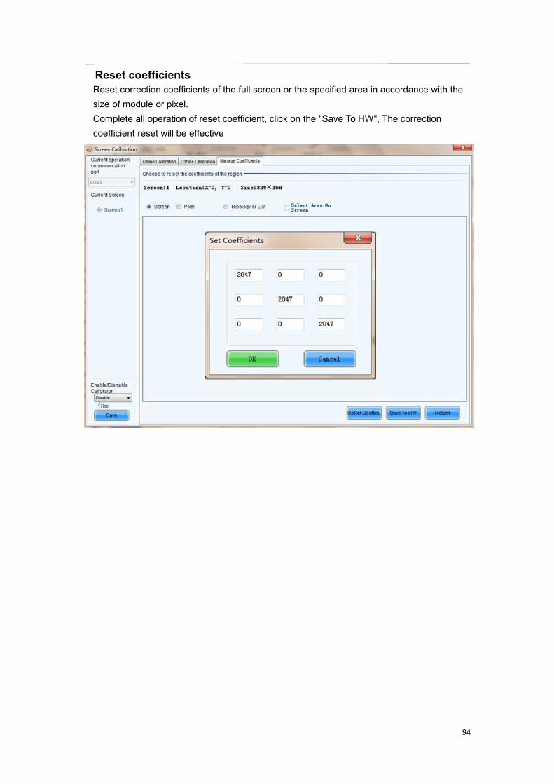
94
Reset coefficientsReset correction coefficients of the full screen or the specified area in accordance with thesize of module or pixel.Complete all operation of reset coefficient, click on the "Save To HW", The correctioncoefficient reset will be effective

95
9.11 Monitor the System
Mars series control system provides monitoring function, covering DVI signal of sending
card, hardware status, temperature, humidity, smoke, fan, power supply, cabinet, and door
status. Supports ordinary screen and screen combination surveillance.
Click to enter the monitoring interface, and click to check
hardware status data of all screens of this system. Then click to performmonitoring configuration.
Monitoring RefreshThis button is used to update the monitored data.SettingsThis button is used to edit the contents to be monitored and set rules for alarm.

96
Refresh periodModify refresh period and reread times when reading the status failed at the refresh periodinterface, wherein the period is the period of refreshing the monitoring data.If all screens are registered to the NovaCare server, check “Auto refresh” to performremote monitoring.
Auto RefreshIf this option is check, NovaLCT-Mars will automatically check the status and parametersbeing monitored and update the monitored data periodically according to the period setting.Retry times after read status failedThis parameter determines how many time NovaLCT-Mars will retry to check the status andparameters being monitored when it fails in doing so.
97
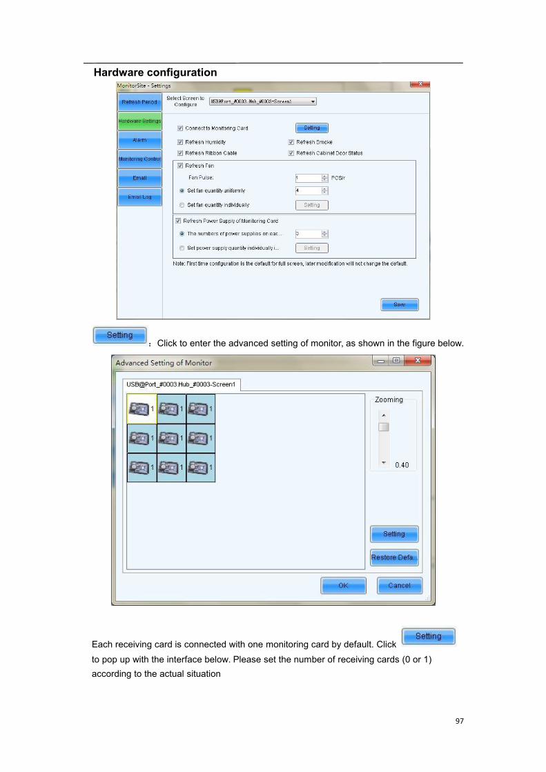
Hardware configuration
:Click to enter the advanced setting of monitor, as shown in the figure below.
Each receiving card is connected with one monitoring card by default. Clickto pop up with the interface below. Please set the number of receiving cards (0 or 1)according to the actual situation
98
.
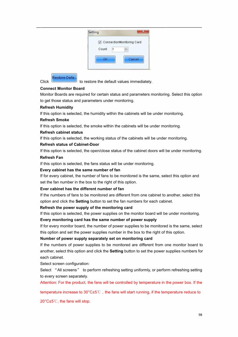
Click to restore the default values immediately.
Connect Monitor BoardMonitor Boards are required for certain status and parameters monitoring. Select this optionto get those status and parameters under monitoring.Refresh HumidityIf this option is selected, the humidity within the cabinets will be under monitoring.Refresh SmokeIf this option is selected, the smoke within the cabinets will be under monitoring.Refresh cabinet statusIf this option is selected, the working status of the cabinets will be under monitoring.Refresh status of Cabinet-DoorIf this option is selected, the open/close status of the cabinet doors will be under monitoring.Refresh FanIf this option is selected, the fans status will be under monitoring.Every cabinet has the same number of fanIf for every cabinet, the number of fans to be monitored is the same, select this option andset the fan number in the box to the right of this option.Ever cabinet has the different number of fanIf the numbers of fans to be monitored are different from one cabinet to another, select thisoption and click the Setting button to set the fan numbers for each cabinet.Refresh the power supply of the monitoring cardIf this option is selected, the power supplies on the monitor board will be under monitoring.Every monitoring card has the same number of power supplyIf for every monitor board, the number of power supplies to be monitored is the same, selectthis option and set the power supplies number in the box to the right of this option.Number of power supply separately set on monitoring cardIf the numbers of power supplies to be monitored are different from one monitor board toanother, select this option and click the Setting button to set the power supplies numbers foreach cabinet.Select screen configuration:Select “All screens” to perform refreshing setting uniformly, or perform refreshing settingto every screen separately.Attention: For the product, the fans will be controlled by temperature in the power box. If the
temperature increase to 30°C±5℃,the fans will start running, if the temperature reduce to
20°C±5℃, the fans will stop.
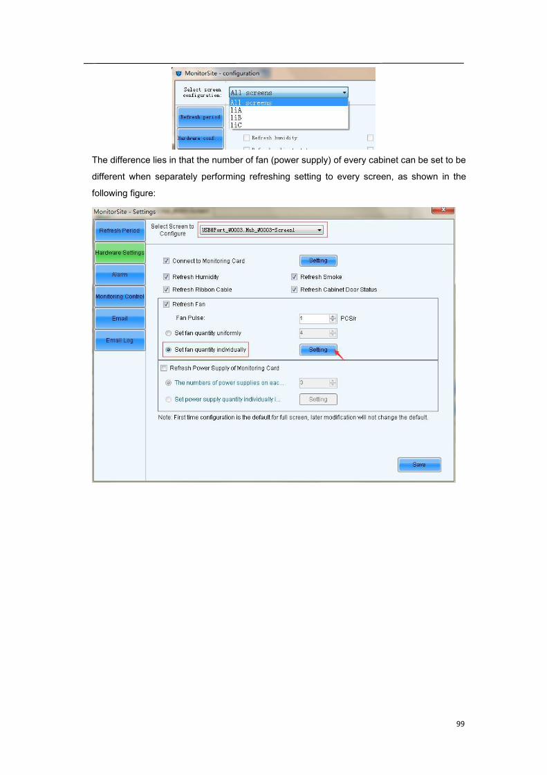
99
The difference lies in that the number of fan (power supply) of every cabinet can be set to be
different when separately performing refreshing setting to every screen, as shown in the
following figure:
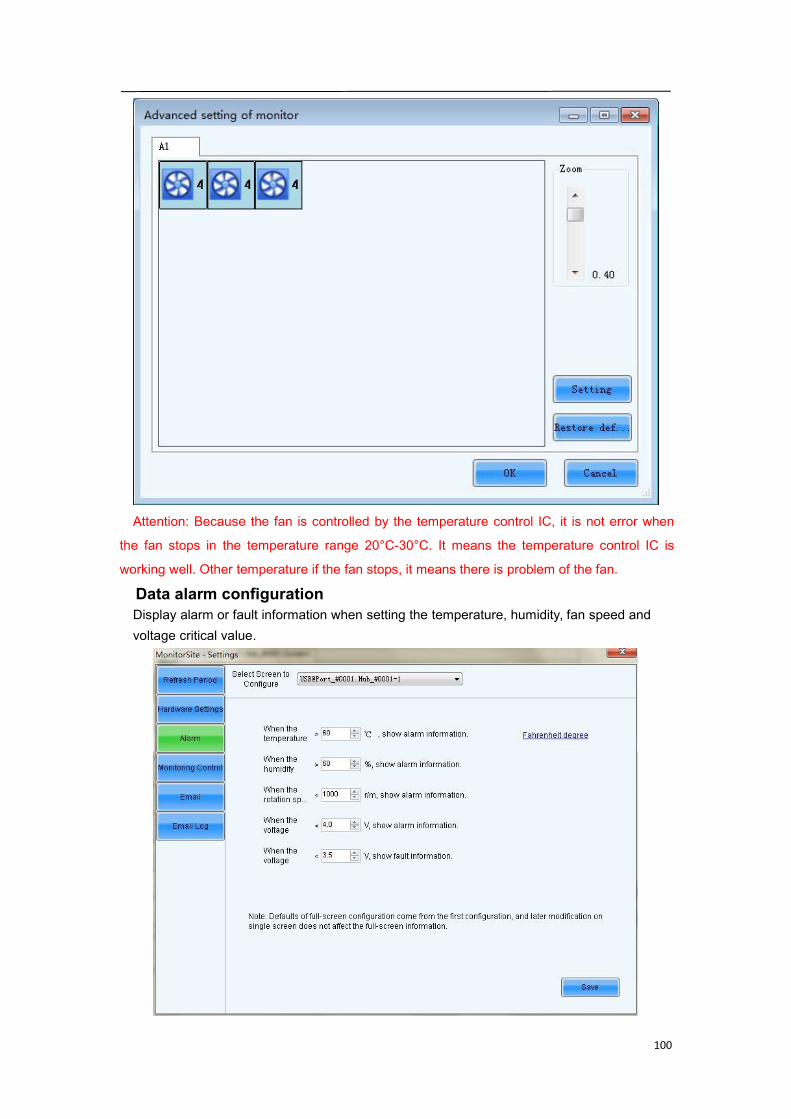
100
Attention: Because the fan is controlled by the temperature control IC, it is not error when
the fan stops in the temperature range 20°C-30°C. It means the temperature control IC is
working well. Other temperature if the fan stops, it means there is problem of the fan.
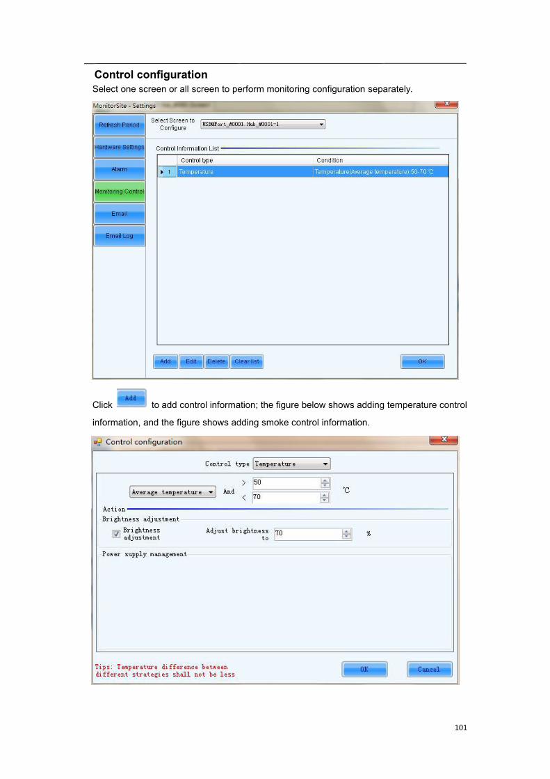
Data alarm configurationDisplay alarm or fault information when setting the temperature, humidity, fan speed andvoltage critical value.
101
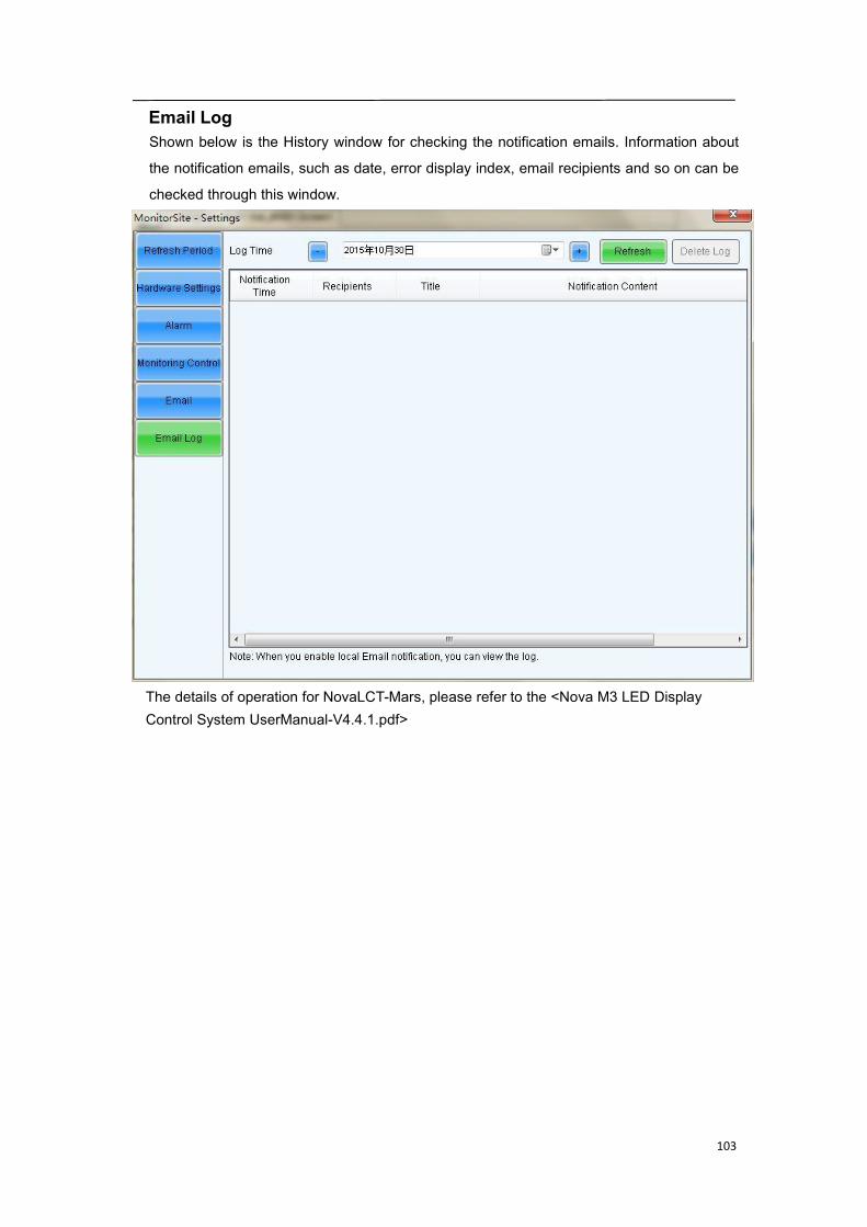
Control configurationSelect one screen or all screen to perform monitoring configuration separately.
Click to add control information; the figure below shows adding temperature control
information, and the figure shows adding smoke control information.

102
Email settingShown below is the page for email notification setting. Set the email notification according tothe instructions given on the page.If the sending system report Email is enabled, the regular sending could be set.
103
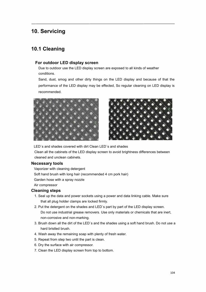
Email LogShown below is the History window for checking the notification emails. Information about
the notification emails, such as date, error display index, email recipients and so on can be
checked through this window.
The details of operation for NovaLCT-Mars, please refer to the <Nova M3 LED DisplayControl System UserManual-V4.4.1.pdf>
104
10. Servicing
10.1 Cleaning
For outdoor LED display screenDue to outdoor use the LED display screen are exposed to all kinds of weatherconditions.Sand, dust, smog and other dirty things on the LED display and because of that the
performance of the LED display may be effected, So regular cleaning on LED display is
recommended.
LED`s and shades covered with dirt Clean LED`s and shadesClean all the cabinets of the LED display screen to avoid brightness differences betweencleaned and unclean cabinets.
Necessary toolsVaporizer with cleaning detergentSoft hand brush with long hair (recommended 4 cm pork hair)Garden hose with a spray nozzleAir compressor
Cleaning steps1. Seal up the data and power sockets using a power and data linking cable. Make sure
that all plug holder clamps are locked firmly.2. Put the detergent on the shades and LED`s part by part of the LED display screen.
Do not use industrial grease removers. Use only materials or chemicals that are inert,non-corrosive and non-marking.
3. Brush down all the dirt of the LED`s and the shades using a soft hand brush. Do not use ahard bristled brush.
4. Wash away the remaining soap with plenty of fresh water.5. Repeat from step two until the part is clean.6. Dry the surface with air compressor.7. Clean the LED display screen from top to bottom.
105
10.2 Calibration
Factory calibrationIn order to achieve color uniformity among all cabinets of the same display the cabinets
can be color calibrated to improve display effect of the LED display screen. The manufacturercan do calibration before goods are delivered out of factory.
Site calibrationWhen the LED display screen is running for a long time, for example for one year, some
part of the display screen may play a different image from other parts. Chromatic aberration
will appear on the LED display screen. Then a site color calibration is needed to achieve color
uniformity among all cabinets of the LED display screen, please contact Sales & Service for
further details.
106
10.3 Replacement steps
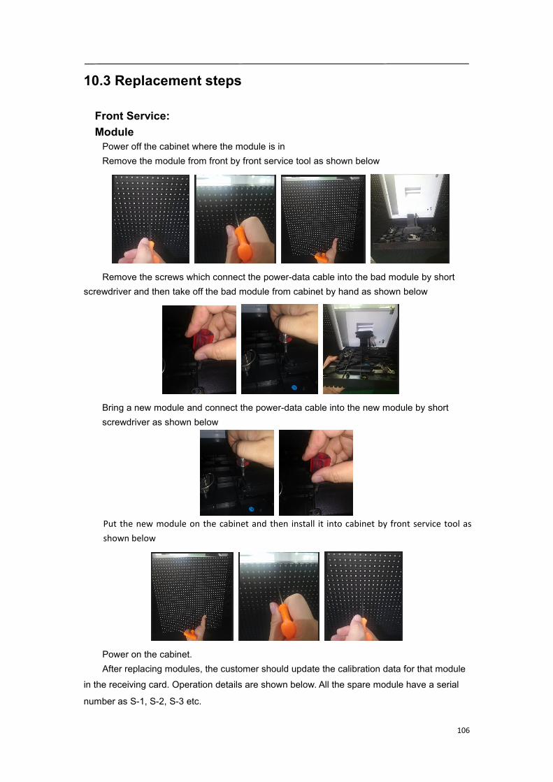
Front Service:ModulePower off the cabinet where the module is inRemove the module from front by front service tool as shown below
Remove the screws which connect the power-data cable into the bad module by shortscrewdriver and then take off the bad module from cabinet by hand as shown below
Bring a new module and connect the power-data cable into the new module by shortscrewdriver as shown below
Put the new module on the cabinet and then install it into cabinet by front service tool asshown below
Power on the cabinet.After replacing modules, the customer should update the calibration data for that module
in the receiving card. Operation details are shown below. All the spare module have a serial
number as S-1, S-2, S-3 etc.
107
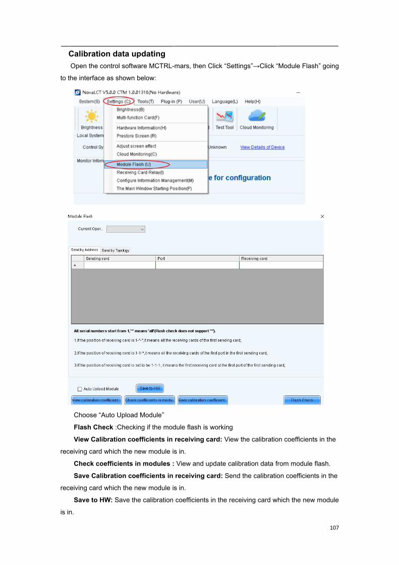
Calibration data updatingOpen the control software MCTRL-mars, then Click “Settings”→Click “Module Flash” going
to the interface as shown below:
Choose “Auto Upload Module”
Flash Check :Checking if the module flash is working
View Calibration coefficients in receiving card: View the calibration coefficients in the
receiving card which the new module is in.
Check coefficients in modules : View and update calibration data from module flash.
Save Calibration coefficients in receiving card: Send the calibration coefficients in the
receiving card which the new module is in.
Save to HW: Save the calibration coefficients in the receiving card which the new module
is in.

108
Open Power boxBefore replace the bad parts in/on power box, you need to remove all the modules whichin on the front of the power box.Put down the power box as shown below
Open the door of the power box as shown below

109
Power-data cablePower off the cabinet where the power-data cable is inRemove the modules which connect the bad power-data cable by front service tools assame as the module replacement steps.Remove the screws which connect the bad power-data cable into the modules by shortscrewdriver and take away modules as shown below
Remove the screws which connect the bad power-data cable into the power box byscrewdriver and take away the bad power-data cable as shown below
Bring a new power data cable and install it into the power box first by screwdriver as shownbelow
Install back the modules which connect to the new power-data cable as shown below, andthen install back all the module as same as the modules replacement steps
Power on the cabinet.
110
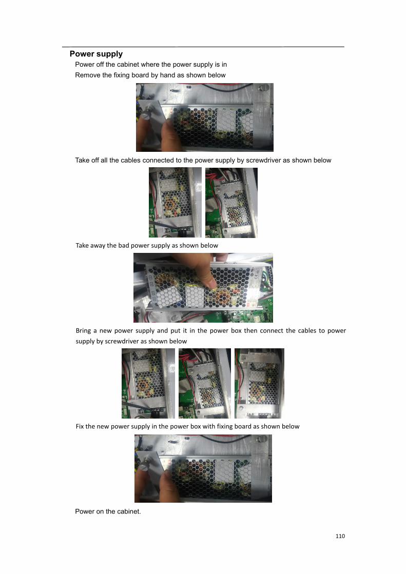
Power supplyPower off the cabinet where the power supply is inRemove the fixing board by hand as shown below
Take off all the cables connected to the power supply by screwdriver as shown below
Take away the bad power supply as shown below
Bring a new power supply and put it in the power box then connect the cables to powersupply by screwdriver as shown below
Fix the new power supply in the power box with fixing board as shown below
Power on the cabinet.
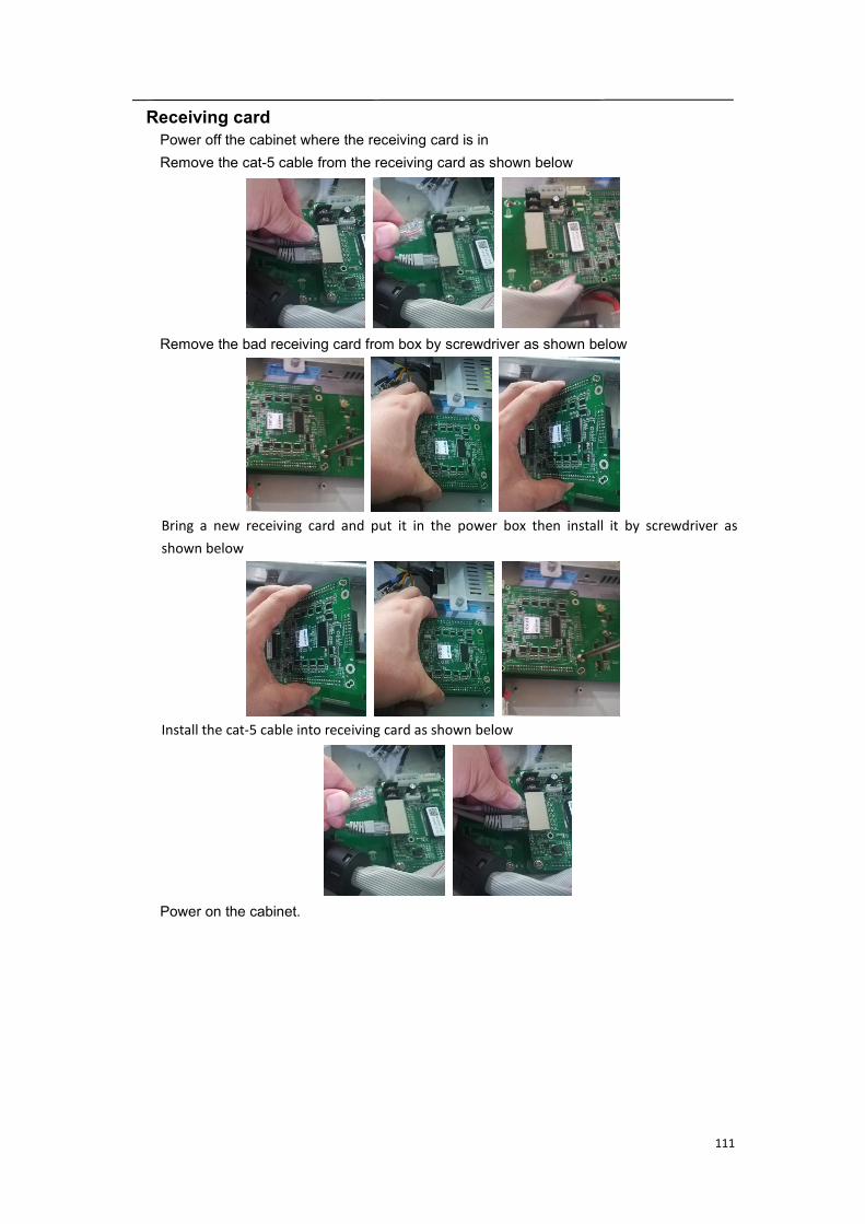
111
Receiving cardPower off the cabinet where the receiving card is inRemove the cat-5 cable from the receiving card as shown below
Remove the bad receiving card from box by screwdriver as shown below
Bring a new receiving card and put it in the power box then install it by screwdriver asshown below
Install the cat-5 cable into receiving card as shown below
Power on the cabinet.
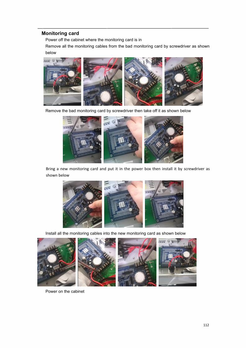
112
Monitoring cardPower off the cabinet where the monitoring card is inRemove all the monitoring cables from the bad monitoring card by screwdriver as shownbelow
Remove the bad monitoring card by screwdriver then take off it as shown below
Bring a new monitoring card and put it in the power box then install it by screwdriver asshown below
Install all the monitoring cables into the new monitoring card as shown below
Power on the cabinet
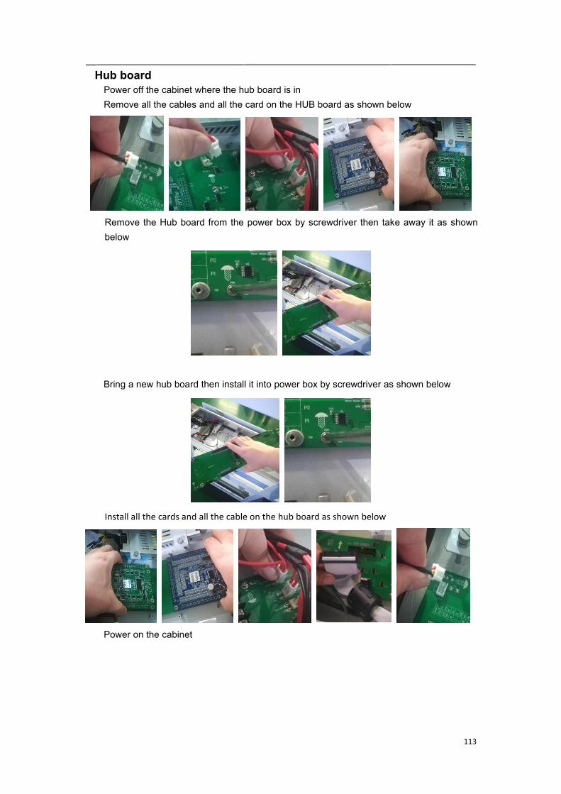
113
Hub boardPower off the cabinet where the hub board is inRemove all the cables and all the card on the HUB board as shown below
Remove the Hub board from the power box by screwdriver then take away it as shownbelow
Bring a new hub board then install it into power box by screwdriver as shown below
Install all the cards and all the cable on the hub board as shown below
Power on the cabinet
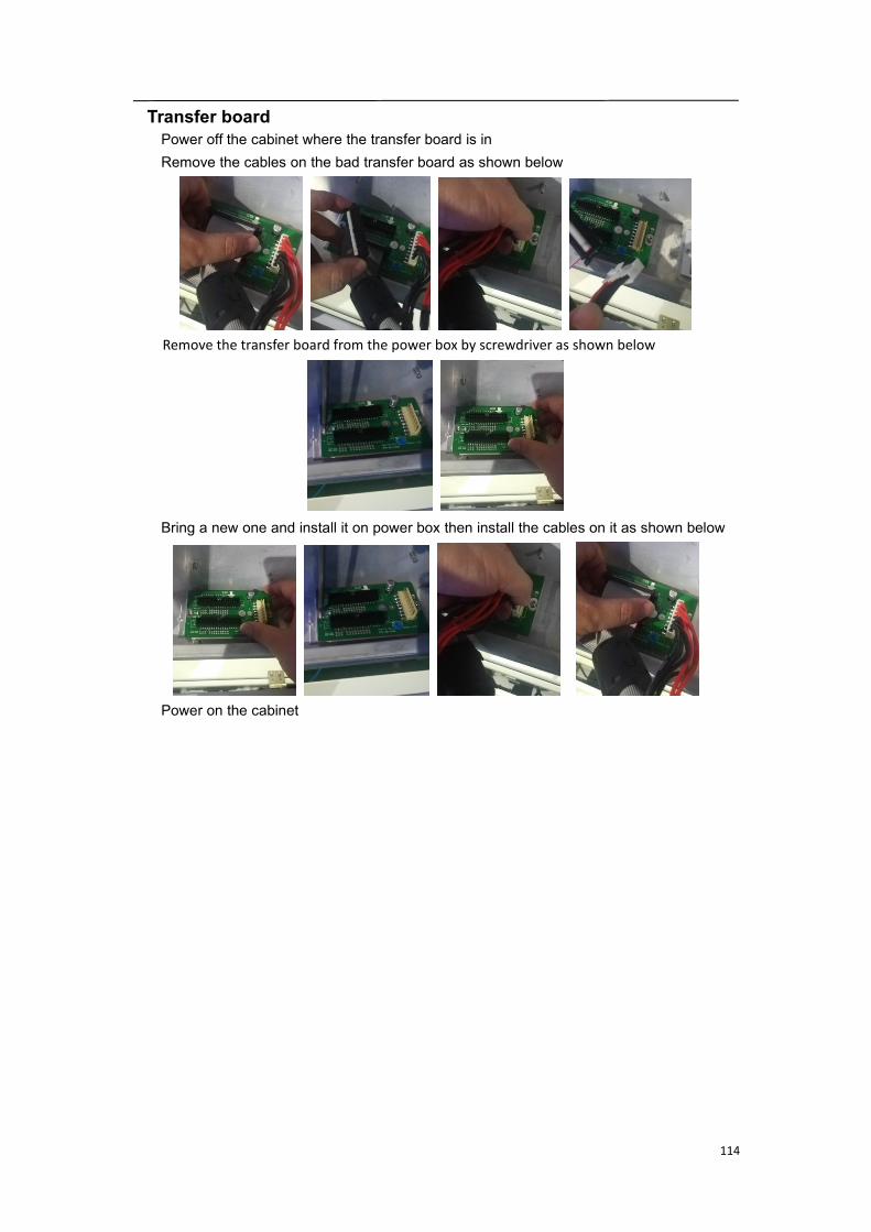
114
Transfer boardPower off the cabinet where the transfer board is inRemove the cables on the bad transfer board as shown below
Remove the transfer board from the power box by screwdriver as shown below
Bring a new one and install it on power box then install the cables on it as shown below
Power on the cabinet
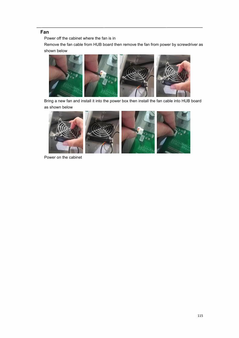
115
FanPower off the cabinet where the fan is inRemove the fan cable from HUB board then remove the fan from power by screwdriver asshown below
Bring a new fan and install it into the power box then install the fan cable into HUB boardas shown below
Power on the cabinet
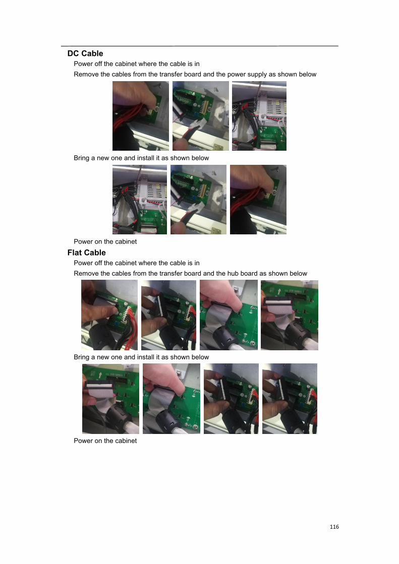
116
DC CablePower off the cabinet where the cable is inRemove the cables from the transfer board and the power supply as shown below
Bring a new one and install it as shown below
Power on the cabinet
Flat CablePower off the cabinet where the cable is inRemove the cables from the transfer board and the hub board as shown below
Bring a new one and install it as shown below
Power on the cabinet
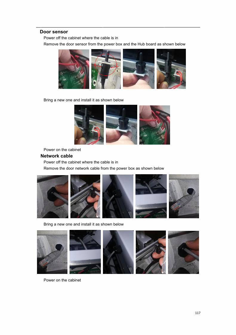
117
Door sensorPower off the cabinet where the cable is inRemove the door sensor from the power box and the Hub board as shown below
Bring a new one and install it as shown below
Power on the cabinetNetwork cablePower off the cabinet where the cable is inRemove the door network cable from the power box as shown below
Bring a new one and install it as shown below
Power on the cabinet
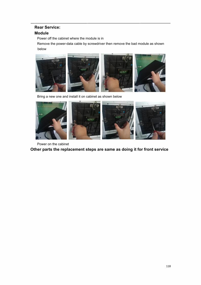
118
Rear Service:ModulePower off the cabinet where the module is inRemove the power-data cable by screwdriver then remove the bad module as shownbelow
Bring a new one and install it on cabinet as shown below
Power on the cabinetOther parts the replacement steps are same as doing it for front service

119
11. Appendix
11.1 Responsibility for the Pay Service(Cost to Customers)
When the service is requested, in spite of in warranty, we may chargeyou for a visit from a service technician in the following cases.
Not a product defectCleaning of the product, Adjustment, Explanation, Re-installation and etc.If a service technician gives instructions on how to use product or simply adjusts option
without disassembling product.If a defect is caused by external environmental factors(Internet, Antenna, wired signal,
etc)If a product is re-installed or devices are connected additionally after installing the
purchased product for the first time.If a product is re-installed to move to a different spot or to move to a different house.If customer requests instructions on how to use because of another company`s product.If customer requests instructions on how to use the network or another company`s
program.If customer requests software installation and setup for the product.If a service technician removes/cleans dusts or foreign materials inside of the product.If customer requests an installation additionally after purchasing a product through home
shopping or online.A product damage cased by customer`s faultProduct damage caused by customer`s mishandling or wrong repair.If a product damage is caused by:External impact or drop.Use of supplier or separately sold product unspecified by Samsung.Repair from a person besides an engineer of outsourcing service company or partner of
Samsung Electronics Co.Ltd.Remodeling or repairing the product by customer.Using it with incorrect voltage or non-authorized electrical connections.Not following the “cautions” in User manual.OthersIf product fails by natural disaster.(lighting, fire, earthquake, flood damage, etc)If consumable components are used up.(Battery, Toner, Fluorescent lights, Head, Vibrator,
Lamp, Filter, Ribbon, etc)-If customer requests a service in case the product has no defect,
service fee may be charged. So please read User Manual first.