Design of Shape-Conforming Nosecone for Optimal Fluid ...
16
e University of Akron IdeaExchange@UAkron Honors Research Projects e Dr. Gary B. and Pamela S. Williams Honors College Spring 2018 Design of Shape-Conforming Nosecone for Optimal Fluid Flow from Transonic to Supersonic Range Anna Tombazzi [email protected] Please take a moment to share how this work helps you through this survey. Your feedback will be important as we plan further development of our repository. Follow this and additional works at: hp://ideaexchange.uakron.edu/honors_research_projects Part of the Aerodynamics and Fluid Mechanics Commons , Aviation and Space Education Commons , Metallurgy Commons , Navigation, Guidance, Control and Dynamics Commons , Other Electrical and Computer Engineering Commons , Other Materials Science and Engineering Commons , Other Mechanical Engineering Commons , Power and Energy Commons , Space Vehicles Commons , and the Structures and Materials Commons is Honors Research Project is brought to you for free and open access by e Dr. Gary B. and Pamela S. Williams Honors College at IdeaExchange@UAkron, the institutional repository of e University of Akron in Akron, Ohio, USA. It has been accepted for inclusion in Honors Research Projects by an authorized administrator of IdeaExchange@UAkron. For more information, please contact [email protected], [email protected]. Recommended Citation Tombazzi, Anna, "Design of Shape-Conforming Nosecone for Optimal Fluid Flow from Transonic to Supersonic Range" (2018). Honors Research Projects. 672. hp://ideaexchange.uakron.edu/honors_research_projects/672
-
Upload
khangminh22 -
Category
Documents
-
view
0 -
download
0
Transcript of Design of Shape-Conforming Nosecone for Optimal Fluid ...

The University of AkronIdeaExchange@UAkron
Honors Research Projects The Dr. Gary B. and Pamela S. Williams HonorsCollege
Spring 2018
Design of Shape-Conforming Nosecone forOptimal Fluid Flow from Transonic to SupersonicRangeAnna [email protected]
Please take a moment to share how this work helps you through this survey. Your feedback will beimportant as we plan further development of our repository.Follow this and additional works at: http://ideaexchange.uakron.edu/honors_research_projects
Part of the Aerodynamics and Fluid Mechanics Commons, Aviation and Space EducationCommons, Metallurgy Commons, Navigation, Guidance, Control and Dynamics Commons, OtherElectrical and Computer Engineering Commons, Other Materials Science and EngineeringCommons, Other Mechanical Engineering Commons, Power and Energy Commons, Space VehiclesCommons, and the Structures and Materials Commons
This Honors Research Project is brought to you for free and open access by The Dr. Gary B. and Pamela S. WilliamsHonors College at IdeaExchange@UAkron, the institutional repository of The University of Akron in Akron, Ohio,USA. It has been accepted for inclusion in Honors Research Projects by an authorized administrator ofIdeaExchange@UAkron. For more information, please contact [email protected], [email protected].
Recommended CitationTombazzi, Anna, "Design of Shape-Conforming Nosecone for Optimal Fluid Flow from Transonic to SupersonicRange" (2018). Honors Research Projects. 672.http://ideaexchange.uakron.edu/honors_research_projects/672

Tombazzi 1
Design of Shape-Conforming Nosecone for Optimal Fluid
Flow from Transonic to Supersonic Range
Senior Honors/Design Project 4200:497
Anna Tombazzi
Faculty Advisor: Dr. Jiahua Zhu
April 27, 2018
Tombazzi 2
Executive Summary
Background
Modern flight vehicles, such as rockets, missiles, and airplanes, experience a force caused by
forebody wave drag during flight. This drag force is induced on the vehicle body when the
frontal point of the vehicle breaks the air pressure wave during flight. Efforts to reduce this wave
drag force in order to improve flight efficiency include modifying the nosecone profiles of flight
vehicles.
Different nosecone profiles are optimal for reducing drag at different velocities and start to make
a notable difference above Mach 1. Unfortunately, a flight vehicle can only sport one nosecone
during its entire flight, even though it experiences a range of velocities. Therefore, no matter
what nosecone is selected for the vehicle, there is always a tradeoff in performance because the
nosecone which has an optimal drag characteristic for one velocity is sub-par at another velocity.
This project revolved around creating a design to make the transformation between two nosecone
shapes possible midflight, in order to avoid efficiency tradeoffs associated with just using one
nosecone geometry.
Results
OMMITTED
Conclusion
A design was created to make the transformation of nosecone shapes from a ¾ Parabolic profile
to a ½ Power Series profile possible, mid-flight. Using a novel nosecone assembly, shape
memory alloys (SMAs) and an electronics system, this transition will be dictated by a vehicle’s
real-time flight velocity. Electronics sense the change in velocities and activate the
transformation through a release of current once the rocket reaches Mach 1.2.
OMMITTED
Technical, Career, and Personal Implications
This technology could benefit society through its use in aerospace applications to improve flight
efficiency. On a more personal level, it could improve the possibility of opening up supersonic
flight to the public once again. For example, Boom Supersonic is currently designing planes which
they hope the public will one day use as a mode of transportation. However, there are many design
challenges as one might imagine- including cutting down the drag resistance experienced by the
plane inflight, which translates to having to carry more fuel.
This project was created in an effort to provide a shape-changing nosecone for use on the
Akronauts Rocket Design Team, at the University of Akron. At one of the competitions the team
competes in, rockets are launched as high as 30,000 ft. When rockets are designed to reach this
altitude, they most likely will break Mach 1 and closely approach Mach 2, calling for a device like
this nosecone which can change shape for each velocity milestone.

Tombazzi 3
This project was inspired not only by the rocket team at the University of Akron, but also by a 2-
minute briefing of shape memory alloys given during a material science lecture. Since the start of
this project, I have learning an incredible amount about the chemistry and material science behind
shape memory alloys. I have also had the opportunity to learn about electrical systems, and learn
softwares like Matlab and Solidworks, which were required in order to bring this design to life.
Recommendations
OMMITTED

Tombazzi 4
Introduction
For a rocket in flight, there are many forces that effect both the flight profile and fuel efficiency.
One of these forces is the drag force experienced, which can be split into two components- wave-
drag, and skin-friction drag. Drag in-flight for a rocket is undesirable mainly because it slows the
rocket down, causing it to require more fuel to reach the same altitude. Rocket fuel is not only
extremely costly but increasing the quantity of rocket fuel onboard also increases the total weight
of the rocket, affects stability, and alters other factors in flight. Therefore, one of the primary
goals when designing the exterior of a rocket is to minimize each parts’ drag coefficient, which
corresponds directly to the magnitude of the drag force that will be imposed on that part.
The wave-drag, which is caused by the pressure forces on the rocket normal to the surface, is
present on the nosecone, fins, and the after-body. Forebody wave-drag is induced by the
nosecone, and as such, nosecones are designed in order to bring down the drag force on the
rocket during flight. The magnitude of nosecone wave-drag is dictated by not only its shape, but
also by the rocket’s velocity, and fineness ratio, which is the ratio of a nosecone’s length to its’
largest diameter (1). Fineness ratio is usually limited by the rocket’s total weight requirements,
as the rocket’s velocity is predetermined from the mission of the rocket’s flight. There are many
characteristic nosecone shapes which a modern rocket nosecone may be modeled after, namely
the Tangent Series, Power Series, Parabolic Series, Haack Series, and the Von Karman (2).
These nosecones are identified by their individual characteristic equation, which describes the
curvature that the nosecone follows.
As rockets travel through the transonic region, which begins at Mach 0.8, and approach the speed
of sound, Mach 1, the wave-drag that the rocket experiences sharply increases. Since wave-drag
is a function of a rocket’s Mach number, each nosecone shape has different drag properties at
different velocities. The preferred nosecone shapes corresponding to the Mach number is
illustrated in Figure 1 (2). As seen, one shape may be preferred over the others at a certain Mach
number, but will not be optimal over the total velocity range of the flight. Because there is a drag
trade-off during flight with any nosecone choice, it is traditional to choose a nosecone shape
which will have an optimal drag characteristic for the velocity that will be experienced the most
frequently during the flight.

Tombazzi 5
Figure 1. The optimal nosecone shapes for drag correspond to Mach Number. 1 is superior, 2 is good, 3 is fair, and 4 is
unsatisfactory (2).
However, rockets soar through a wide variety of velocities during flight, from subsonic, to
transonic, to supersonic, often not staying at the same Mach number for an extended period of
time. Even if a nosecone is selected for optimal drag resistance at supersonic speed, drag
tradeoffs will occur at other velocities. Furthermore, if a rocket is relaunched later for a different
mission, where is now experiences a different flight velocity profile, the previously used
nosecone may not be optimal over any of the velocities that the rocket will now fly at. At this
point, either a new nosecone must be manufactured, or the rocket unnecessarily suffers from
increased forebody wave-drag.
The basis of this project was to design a nosecone which could shape transform in between two
different nosecone shapes, mid-flight, so that the rocket experiences a minimum wave-drag force
throughout its’ entire flight. A sounding rocket designed by the Akronauts Rocket Design Team,
which is expected to reach speeds of 1.9 Mach, was the target body for which this shape-
conforming nosecone was designed for. Two nosecone profiles were chosen for which the
nosecone will transform between. From Figure 1., it is seen that the Von Karman shape
performs well from the transonic region until about 1.2 Mach. After that, from 1.2 Mach through
1.8 Mach, the ½ Power Series design becomes preferable, experiencing less wave-drag from the
fluid flow of air. The governing equations for the curvature of each nosecone shape are as
follows, where L is the total length of the nosecone, R is the final radius, and y is the
instantaneous changing diameter of the nosecone along x, the varying distance from nosecone
tip, as seen in Figure 2 (2).

Tombazzi 6
Figure 2. Illustrates the variables included in the characteristic equations of the nosecone shapes.
Von Karman
Θ = arccos(1 −2𝑥
𝐿) (1)
y = 𝑅
𝑠𝑞𝑟𝑡(𝜋)∗ 𝑠𝑞𝑟𝑡(Θ −
sin(2Θ)
2) (2)
½ Power Series
y = 𝑅 ∗ (𝑥
𝐿)^0.5 (3)
Background
In order to accomplish this change between nosecone shapes mid-flight, the use of a shape
memory alloy was employed. Shape memory alloys(SMAs) are metals which have the ability to
transform between two different shapes. In metals, there exists different solid-state phases.
Austenite is the phase that the metal transitions to at high temperatures, and martensite is the low
temperature phase. The transition temperature range is referred to as the temperature range where
the metal starts transitioning from one phase to another. As denotes the starting temperature
where the alloy starts to change its’ phase from martensite to austenite, whereas Af denotes the
ending temperature where the alloy should be in its austenite phase completely. Likewise, Ms
and Mf refer to the starting and ending temperatures through which the SMA is transforming into
its martensite phase. As seen in Figure 3., there is often a temperature gap between the As and
Ms temperature, which is called its hysteretic loss (3). The temperature transition ranges, such as
As and Af, differ for different shape memory alloys, as the different alloy compositions dictate
the temperatures at which the metal will be in its martensite or austenite phase. Common metals
used for composing shape memory alloys include copper, nitinol, aluminum, iron, gold, and
titanium.

Tombazzi 7
To understand the significance of phase change on of the effect of SMA shape, one must have a
basic understanding of thermodynamics and its effect on the atomic structure of a material.
In order to lower Gibbs Free Energy, there exists an optimal arrangement of atoms within the
SMA at each phase. In the austenite phase, the atoms assume a cubic crystalline structure, but in
the martensite phase, the atoms reorient themselves to form either a tetragonal or monoclinic
crystalline arrangement (4).
When a SMA cools from austenite to martensite without being under stress, twinned martensite
is formed, meaning that the macroscopic shape of the material stays the same because its’ atoms
assume the tetragonal structure by a freely rearranging themselves. However, if the SMA is
cooled under a stress, then detwinned martensite is formed (5). The external stress does not allow
the atoms to freely rearrange, and instead they shift to the tetragonal arrangement with respect to
the load. For example, if the SMA is in tension stress during this phase change, this would cause
a macroscopic extension of the material in the direction of the stress, as illustrated in Figure 4
(3).
Thermomechanical processing, called training, is the process during which a SMA is repeatedly
heated to its austenite phase and cooled to its martensite phase while under stress. After a
number of cycles, it will automatically revert to its detwinned martensite structure after cooling,
even after the stress is removed (7). Similarly, when the SMA is heated through its austenite
transition range, its atoms will reform their cubic structure, no matter what shape the SMA has
been contorted to in its martensite phase. The memory of the alloy where its low temperature
detwinned martensite structure is retained after the its transformation from austenite to
martensite without stress is called a two-way shape memory effect. In the case of detwinned
martensite formed under tension stress, when the SMA forms its corresponding austenite phase,
the material will contract macroscopically, caused by the microscopic contract of atoms back

Tombazzi 8
into their cubic structure (6). A visual of this is seen in Figure 5. In Figure 6., the characteristic
behavior of a SMA change in strain with temperature and applied stress is seen.
Besides differing transition temperature ranges, different SMAs have unique characteristics
corresponding to strain, corrosion, fracture properties, along with the number of cycles from
austenite to martensite a SMA will be able to exhibit its one-way or two-way memory before
breakdown. The benefits of Ni-Ti alloys with respect to its counterparts are seen by a comparison
of its properties with other alloys, as seen in Figure 7 (7).
Figure 7. Properties of several SMAs which are manufactured by Advanced Material Technologies Pte Ltd (7).
The use of SMAs has become increasing popular in a variety of applications of the past few
years, as they have been recognized for their ability to transform shape with just a temperature
change. For example, in aerospace applications, this property been proven useful in the
hydraulics in plane wings, some of which are now being replaced with SMA actuators, running
off of the heat from the engines. Not only are SMAs incredibly energy dense, but they are also
Tombazzi 9
very reliable, as the shape change relies on thermodynamic laws, instead of mechanical
components.
In addition to being used in aerospace applications, the use of SMA are also being explored in
the fields of biomedical engineering, robotics, and automotive engineering.
In this application, the use of SMAs were chosen because of their ability assume a different
shape even if they are against external stress. Mechanical mechanisms of contorting the nosecone
would not only be unreliable, but also extremely space-consuming. At each contortion point,
there would need to be an individual mechanism to move the nosecone, since each point of the
nosecone would have to be adjusted differently. However, a single current can be used to adjust
the SMA wires, where they will all move simultaneously in different ways, to elicit the desired
nosecone shape change.
Design and Materials
Nosecone Shell Design
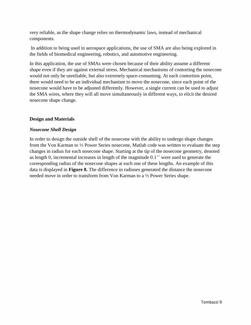
In order to design the outside shell of the nosecone with the ability to undergo shape changes
from the Von Karman to ½ Power Series nosecone, Matlab code was written to evaluate the step
changes in radius for each nosecone shape. Starting at the tip of the nosecone geometry, denoted
as length 0, incremental increases in length of the magnitude 0.1’’ were used to generate the
corresponding radius of the nosecone shapes at each one of these lengths. An example of this
data is displayed in Figure 8. The difference in radiuses generated the distance the nosecone
needed move in order to transform from Von Karman to a ½ Power Series shape.
Tombazzi 10
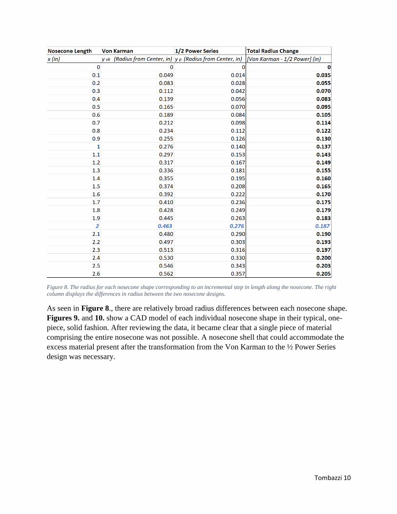
Figure 8. The radius for each nosecone shape corresponding to an incremental step in length along the nosecone. The right
column displays the differences in radius between the two nosecone designs.
As seen in Figure 8., there are relatively broad radius differences between each nosecone shape.
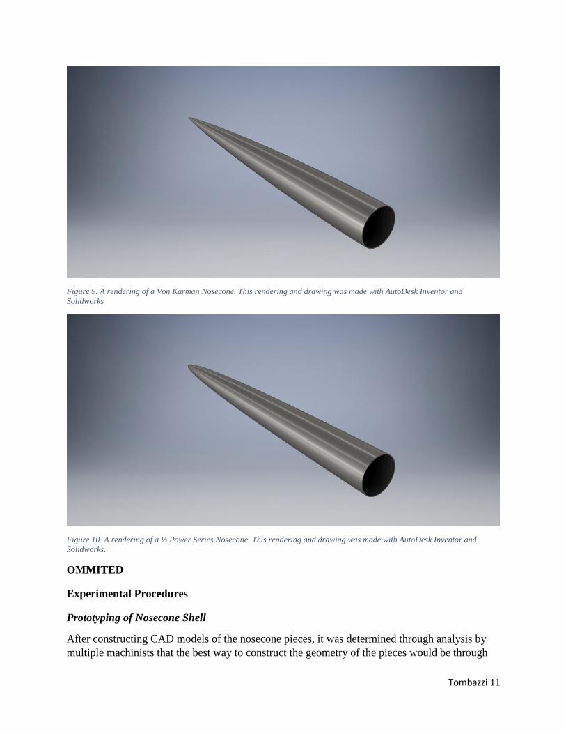
Figures 9. and 10. show a CAD model of each individual nosecone shape in their typical, one-
piece, solid fashion. After reviewing the data, it became clear that a single piece of material
comprising the entire nosecone was not possible. A nosecone shell that could accommodate the
excess material present after the transformation from the Von Karman to the ½ Power Series
design was necessary.
Tombazzi 11
Figure 9. A rendering of a Von Karman Nosecone. This rendering and drawing was made with AutoDesk Inventor and
Solidworks
Figure 10. A rendering of a ½ Power Series Nosecone. This rendering and drawing was made with AutoDesk Inventor and
Solidworks.
OMMITED
Experimental Procedures
Prototyping of Nosecone Shell
After constructing CAD models of the nosecone pieces, it was determined through analysis by
multiple machinists that the best way to construct the geometry of the pieces would be through
Tombazzi 12
3D printing. Before seeking out a metal 3D printing company to make this print, the possibility
of printing out one piece of each geometry for prototyping at the University of Akron was
explored. This was to ensure that the dimensions from the CAD drawings were correct and that
the nosecone pieces would fit together correctly, before investing in an expensive aluminum 3D
print. The mechanical engineering department did not have a plastic 3D printer large enough to
print a nosecone piece 24’’ long, so it was decided that the nosecone pieces would be split up
into different sections.
The nosecone pieces were sectioned into top, middle, and bottom sections. The middle sections
were omitted from the print for the sake of time, but also because the middle sections were
constrained by the top and bottom sections.
Therefore, if the top and bottom sections pieced together correctly, the middle sections must as
well. One top section and one bottom section from each geometry was printed.
Training of SMA wires
In order to train the SMA wires supplied by Fort Wayne Metals, the expertise of NASA material
scientist and SMA expert, Santo Padula, was employed. First, each wire was subjected to 200
MPa of constant stress. The weight in pounds, F, needed to induce 200 MPa of stress on each
piece of wire, as a function of wire gauge g, was determined according to Equation 3. While
under this stress, current supplied by a power source was ran through the wire, heating up the
wire and inducing the solid-state phase change from martensite to austenite. Once the phase
change had finished, characterized by heating the alloy past its Af temperature of the alloy, the
current source was turned off and the wire was allowed to cool back to its martensite state.
During cooling under stress, detwinning was experienced in the metal, as evident by its
relaxation and resulting elongated martensite state. This heat cycling process was repeated until
the strain in the metal changed no more than 1% from its previous strain in each phase.
F (lbf) = (200 𝑀𝑃𝑎) ∗ 106 ∗𝜋∗(𝑔)2
4∗ (
25.4𝑚𝑚
1𝑖𝑛)
2
∗ (1𝑚
1000𝑚𝑚)
2
∗ (1𝑙𝑏𝑓
4.4𝑁) (3)
The weights used to apply constant stress to the wires were steel weights created for the
application of weight room workouts such as benching. These weights were used to induce stress
on the material because the hole in the center of each of these weights created a convenient
attachment point. A weight stand was created to support the weights during SMA training and
was designed so that weights could be easily added or removed from the stand. As seen in
Figure 17., the weight-stand consists of a large eyebolt, plywood, and a circulate 1/16’’ steel
plate backing it. The 1/16’’steel plate and ½’’plywood are connected to the eyebolt with 3/8’’
nuts.

Tombazzi 13
Figure 17. The weight-stand, created to support circular weights used for bench pressing. A steel plate on the bottom reinforces
the plywood, and the eyebolt enables easy connection to the rest of the SMA training set up.
A 1/16’’ piece of aircraft cable attaches to the eyebolt with the help of a wire compression
sleeve. During training, this weight-stand with the weights hang over a horizontal pulley attached
to the edge of a workbench. The aircraft cable continues to a set screw shaft coupler, which
connects the aircraft cable to the SMA wire. The SMA wire, which is parallel to the workbench
surface during training, is attached to another set screw shaft coupler. This coupler is then
wrapped in electrical tape to insulate it and is clamped tightly with a vice that is bolted into the
table. Three power sources with constant current/varying voltage are wired in parallel and
connected to each end of the wire. On the workbench, directly below the wire, a piece of paper
next to a ruler was taped down. With each expansion and contraction cycle, the different lengths
of the wire were recorded, making it possible to know when to stop the thermocycling procedure.
A full set-up of the training procedure is seen in Figure 18.

Tombazzi 14
Figure 18. The set-up of the SMA wire training process. As seen, weights are supported by a weight-stand, hanging over the edge
of the work bench supported by a horizontal pulley. Set crew couplers connect aircraft cable to the wire, and allow the gripping
of the wire by a vice bolted to the table. Three current sources supply the current necessary to heat the wire beyond its transition
temperature.
Results
Nosecone Outer Shell Prototyping
OMITTED
Conclusions and Recommendations
OMMITED
The complete assembly of this system was not possible due to a lack of funding to pay for a
metal 3D printing company to print the outside geometry out of aluminum. Several 3D printing
companies with metal 3D printers were contacted, but they were unable to make a complete
donation of the parts at this time. When the nosecone shell pieces are printed, this design will be
assembled and launched on a rocket that is projected to achieve velocities over 1.2 Mach. Such a
rocket will be launched by the Akronauts Rocket Design Team, at the University of Akron, at the
Spaceport America Cup in New Mexico in the future.
In the future, SMA wires will also be considered for use in other systems within the high
powered sounding rockets, built by the Akronauts. Upcoming projects for which this material
may be useful for include airbrakes and canted fins for spin induced stabilization. In industry,
the use of shape memory alloys is also projected to increase across multiple different fields, as
more individuals become familiar with SMAs and their potential.

Tombazzi 15
Acknowledgements
Special thanks goes to Santo Padula, PhD., a materials specialist who work with SMAs at the
NASA Glenn Research Center. Santo was instrumental in facilitating a deeper understanding of
SMAs, which was necessary for this project. Santo also helped instruct on the procedures
necessary to train the SMA wires. A thank you also goes out to Shane Benner, for his expertise
in electronics. Shane provided critical guidance for the set-up of the power sources use to help
with the SMA training procedures.
Works Cited
1. Department of Defense. “Design of Aerodynamically Stablized Free Rockets.” Military
Handbook. Published 17 July 1990.
2. Crowell, Gary Sr. “The Descriptive Geometry of Nose Cones”. United States Patents. 11 Apr
1996. http://www.if.sc.usp.br/~projetosulfos/artigos/NoseCone_EQN2.PDF. Accessed 21 Apr
2018.
3. Wanhill, R.J., Ashok,B. “Shape Memory Alloys (SMAs) for Aerospace Applications”
Aerospace Materials and Material Technologies. Chapter 21. Published in Singapore, 2017.
4. Callister, William. Rethwisch, David. “Materials Science and Engineering, An Introduction”
John Wiley & Sons Inc. 2014
5. Otsuka, Wayman. “Shape Memory Materials” Cambridge University Press, Cambridge, 1999.
6. Lexcellent, C. “A general macroscopic description of the thermomechanical behavior of shape
memory alloys”. JMPS 44. 1996.
7. Hartl, Darren. Lagoudas, Dimitris. “Aerospace Applications of Shape Memory Alloys”
Aerospace Engineering Department, Texas A&M University. 2017