On channel estimation and optimal training design for amplify and forward relay networks
Upload
lipoadvisorCategory
view
0download
0
IRRIGATION AND DRAINAGE
Irrig. and Drain. 55: 21–32 (2006)
Published online in Wiley InterScience (www.interscience.wiley.com). DOI: 10.1002/ird.214
DESIGN OF OPTIMAL IRRIGATION NETWORKSy
MENELAOS E. THEOCHARIS1*, CHRISTOS D. TZIMOPOULOS2, STAVROS I. YANNOPOULOS2
AND MARIA A. SAKELLARIOU-MAKRANTONAKI3
1Department of Crop Production, Technological Educational Institute of Epirus, 47100 Arta, Greece2Department of Rural and Surveying Engineering, A.U.TH, 54006 Thessaloniki, Greece
3Department of Agriculture, Crop Production and Rural Environment, University of Thessaly, 38334 Volos, Greece
ABSTRACT
The problem of selecting the best pattern of pipe diameters of an irrigation network has long been given
considerable attention by engineers when designing hydraulic works. The classical optimization techniques, which
have been proposed until now, are the following: (1) the linear programming method; (2) the nonlinear
programming method; (3) the dynamic programming method; and (4) Labye’s method. Mathematical research
of the problem, using the previous methods, is very complex, and for this reason the numerical solution calls for a
lot of calculations, especially in the case of a network with many branches. In this study, the formulation of a new
simplified nonlinear programming method is presented, which can replace the existing ones with the best results. A
comparative evaluation between the proposed simplified method and the general nonlinear programming method
in a particular irrigation network is also developed. The results of the proposed simplified method are fully
identical with the results of the nonlinear programming method. Consequently, this method can be equally used for
the classical methods. Copyright # 2006 John Wiley & Sons, Ltd.
key words: irrigation; network; minimum cost; optimal design; linear method; nonlinear method; dynamic method; simplified method
RESUME
Le probleme du choix du systeme de diametres des canalisations d’un reseau d’irrigation a ete depuis longtemps
l’objet d’une attention particuliere de la part des ingenieurs de conception d’ouvrages hydrauliques. Les
techniques classiques d’optimisation proposees jusqu’a present sont les suivantes: (1) la methode de program-
mation lineaire; (2) la methode de programmation non lineaire; (3) la methode de programmation dynamique; et
(4) la methode du Labye. La solution mathematique du probleme, en utilisant les methodes precedentes, est tres
complexe et demande beaucoup de calculs, particulierement dans le cas d’un reseau avec beaucoup de Ious-
divisions. Dans cette etude, la formulation d’une nouvelle methode simplifiee de programmation non lineaire est
presentee, qui peut remplacer les methodes existantes avec de meilleurs resultats. Une evaluation comparative
entre la methode simplifiee proposee et la methode de programmation non lineaire generale dans un reseau
particulier d’irrigation est egalement developpee. Les resultats de la methode simplifiee proposee sont entierement
identiques aux resultats de la methode de programmation non lineaire. En consequence, cette methode peut
egalement etre employee pour les methodes classiques. Copyright # 2006 John Wiley & Sons, Ltd.
mots cles: irrigation; reseau; cout minimum; conception optimale; methode lineaire; methode non lineaire; methode dynamique; methodesimplifiee
Received 26 August 2005
Copyright # 2006 John Wiley & Sons, Ltd. Accepted 19 October 2005
* Correspondence to: Menelaos E. Theocharis, Department of Crop Production Technological Educational Institute of Epirus, 47100 Arta,Greece. E-mail: [email protected] de reseaux optimaux d’irrigation.

INTRODUCTION
The problem of optimal design of hydraulic networks, using the nonlinear programming method, concludes in a
system of nonlinear equations, where the unknown variables are the available frictional head losses in the network
branches. This system has a precise solution only in the case of a network having pipes in sequence (Swamee et al.,
1973; Swamee and Khanna, 1974; Tzimopoulos, 1982; Theocharis, 2004). For each branched network the system,
which consists of nþ k equations (n is the number of the supplying branches and k is the number of the ends of the
network), is nonlinear, so its complete mathematical solution is impossible (Noutsopoulos, 1969; Watanatada,
1973; Tzimopoulos, 1982; Chiplunkar and Khanna, 1983; Vamvakeridou-Lyroudia, 1990; Theocharis, 2004).
Since the numerical solution of the system calls for a lot of laborious operations, especially in the cases of networks
having many branches, the use of computers is indispensable (Chiplunkar and Khanna, 1983). A method which
does not require the use of computers is based on the observation (Theocharis, 2004) that each supplied branch of
the network tends to raise the economic hydraulic gradient at the junction points, above the economic hydraulic
gradient of the network, which does not include this branch. Thus, if the complete route of the network presenting
the minimum average hydraulic gradient is selected, the economic piezometric line corresponding to this
(assuming that all the other supplied branches are neglected) tends to be raised under the influence of the supplied
branches, which at first had been neglected, so that the final hydraulic gradient does not differ remarkably from this
economic hydraulic gradient. But only one equation is needed to calculate the economic hydraulic gradient
corresponding to the complete route of the network presenting the minimum average gradient. Using the
piezometric heads at the junction points, which have been calculated by the above-mentioned procedure from
the complete route presenting the minimum average gradient, as heads of the supplied branches, the frictional head
losses and the diameters of the pipes within the supplied branches can be easily calculated. In the present work
there is a brief presentation of the proposed simplified optimization method, as well as a comparative evaluation
between this and the general nonlinear programming method. Application and comparative evaluation in a
particular irrigation network are also developed. The results of this comparison show that the total cost of the
network, resulting from the simplified method, differs from the cost of the general method only by 0.022%.
THE NONLINEAR PROGRAMMING OPTIMIZATION METHOD
For further study of the problem the import of certain symbols concerning the network is necessary. The network
endings are called ‘‘ends of the network’’. Every outlet—except from those coinciding with the ends—and every
point of the network where a pipe is branched in more than one pipe are called ‘‘nodes of the network’’. The first
ones are termed ‘‘simple nodes’’ and the second ‘‘junction nodes’’. A junction node may coincide with an outlet.
The part of a network within two successive nodes, or a node and an end, is called a ‘‘pipe (or conduit) of the
network’’. The total number of pipes is equal to the total sum of the nodes and the ends of the network. Each pipe is
denoted by the number of the downstream node or end. In branched networks, every outlet is supplied by only one
pipe and every node or end is joined to the previous node by only one pipe as well. The total number of pipes
within two successive junction nodes or a junction node and an end is defined as a branch of the network. The total
number of branches is equal to the total sum of the junction nodes and the ends. Each branch that leads to an end of
the network is called a ‘‘supplied branch’’ and all those remaining are ‘‘supplying branches’’. The total number of
pipes from the intake of the network up to every outlet is termed ‘‘route of the outlet’’. If an outlet coincides with an
end of the network, the corresponding route is called a ‘‘complete route’’. Each junction node is denoted by Ni,
where i ¼ 1; 2 . . . r . . . n and n is the total number of the nodes within the network. Nodes are numbered in
ascending order from upstream to downstream as N1;N2 . . .Nr . . .Nn. Each end is denoted by Nrj where
r ¼ 1; 2; . . . ; n is the junction node by which the branch is supplied and j ¼ 1; 2; . . . ; p is the number of the
supplied branches beginning from the junction node r. They are numbered from upstream to downstream as
N11 . . .N1j . . .Nr1 . . .Nrj . . .Nn1 . . .Nnj. Each supplying branch is denoted by Si where i is the symbol of
the downstream junction node. They are numbered in ascending order from upstream to downstream as
S1; S2 . . . Sr . . . Sn. Each supplied branch is denoted by Lrj, where r and j are as defined above. They are numbered
from upstream to downstream as: L11 . . . L1j . . . Lr1 . . . Lrj . . . Ln1 . . . Lnj. Each pipe within the supplying branch Si is
22 M. E. THEOCHARIS ET AL.
Copyright # 2006 John Wiley & Sons, Ltd. Irrig. and Drain. 55: 21–32 (2006)

denoted by the symbol sit where t ¼ 1; 2; . . . ; v is the total number of pipes within the supplying branch. Each pipe
within the supplied branch Lrj is denoted by the symbol ‘rjq where q ¼ 1; 2; . . . ; t is the total number of pipes
within the supplied branch. In Figures 1 and 2 a network including the symbols that were described above is
presented.
Consider a single pipe within a branched network. The cost of pipe according to Mandry’s cost function
(Mandry, 1967) is expressed by
C ¼ AD�l ð1Þ
where C is the pipe cost (euros), A and � are constants depending on the material of pipe and determined according
to the least square method, D is the internal diameter of pipe (m) and l is the length of pipe (m). Using the Darcy-
Weisbach formula the frictional head loss is calculated as
�h ¼ �lV2
2gDð2Þ
Figure 1. An ideal branched network
Figure 2. A real branched network
DESIGN OF OPTIMAL IRRIGATION NETWORKS 23
Copyright # 2006 John Wiley & Sons, Ltd. Irrig. and Drain. 55: 21–32 (2006)
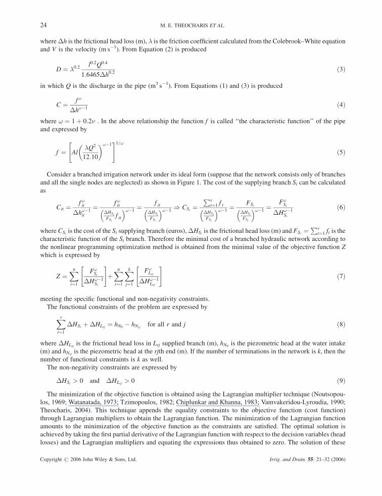
where �h is the frictional head loss (m), � is the friction coefficient calculated from the Colebrook–White equation
and V is the velocity (m s�1). From Equation (2) is produced
D ¼ �0:2 l0:2Q0:4
1:6465�h0:2ð3Þ
in which Q is the discharge in the pipe (m3 s�1). From Equations (1) and (3) is produced
C ¼ f !
�h!�1ð4Þ
where ! ¼ 1 þ 0:2� . In the above relationship the function f is called ‘‘the characteristic function’’ of the pipe
and expressed by
f ¼ Al�Q2
12:10
� �!�1" #1=!
ð5Þ
Consider a branched irrigation network under its ideal form (suppose that the network consists only of branches
and all the single nodes are neglected) as shown in Figure 1. The cost of the supplying branch Si can be calculated
as
Cit ¼f !it
�h!�1it
¼ f !it�HSi
FSi
f it
� �!�1¼ f it
�HSi
FSi
� �!�1) CSi ¼
Pvt¼1 f t
�HSi
FSi
� �!�1¼ FSi
�HSi
FSi
� �!�1¼
F!Si
�H!�1Si
ð6Þ
where CSi is the cost of the Si supplying branch (euros), �HSi is the frictional head loss (m) and FSi ¼Pv
t¼1 ft is the
characteristic function of the Si branch. Therefore the minimal cost of a branched hydraulic network according to
the nonlinear programming optimization method is obtained from the minimal value of the objective function Z
which is expressed by
Z ¼Xni¼1
F!Si
�H!�1Si
" #þXnr¼1
Xkj¼1
F!Lrj
�H!�1Lrj
" #ð7Þ
meeting the specific functional and non-negativity constraints.
The functional constraints of the problem are expressed by
Xri¼1
�HSi þ�HLrj ¼ hN0� hNrj
for all r and j ð8Þ
where �HLrj is the frictional head loss in Lrj supplied branch (m), hN0is the piezometric head at the water intake
(m) and hNrjis the piezometric head at the rjth end (m). If the number of terminations in the network is k, then the
number of functional constraints is k as well.
The non-negativity constraints are expressed by
�HSi > 0 and �HLrj > 0 ð9Þ
The minimization of the objective function is obtained using the Lagrangian multiplier technique (Noutsopou-
los, 1969; Watanatada, 1973; Tzimopoulos, 1982; Chiplunkar and Khanna, 1983; Vamvakeridou-Lyroudia, 1990;
Theocharis, 2004). This technique appends the equality constraints to the objective function (cost function)
through Lagrangian multipliers to obtain the Lagrangian function. The minimization of the Lagrangian function
amounts to the minimization of the objective function as the constraints are satisfied. The optimal solution is
achieved by taking the first partial derivative of the Lagrangian function with respect to the decision variables (head
losses) and the Lagrangian multipliers and equating the expressions thus obtained to zero. The solution of these
24 M. E. THEOCHARIS ET AL.
Copyright # 2006 John Wiley & Sons, Ltd. Irrig. and Drain. 55: 21–32 (2006)

equations results in a minimum cost design if the Lagrangian multipliers are positive. The obtained system of
nonlinear equations is
FSi
�HSi
� �!¼Xnr¼i
Xkj¼1
FLrj
�HLrj
� �!ð10Þ
and
�HLrj ¼ ðhN0� hLrjÞ �
Xri¼1
�HSi ð11Þ
The mathematical solution of the system is very complex and for this reason the numerical solution is achieved
through an iteration procedure, which calls for a lot of calculations, especially in the case of a network with many
branches. The system is usually solved using the secant method (Tzimopoulos, 1982; Theocharis, 2004). Initial values
for �HSið1Þ and�HLrjð1Þ are obtained from the complete route presenting the minimum average gradient and then the
values of�HSið2Þ and�HLrjð2Þ of the first iteration are obtained. The procedure is repeated and the values of the second
iteration are obtained and so on, until the convergence of the values which is successful after at least 12 iterations.
THE PROPOSED SIMPLIFIED NONLINEAR PROGRAMMING OPTIMIZATION METHOD
If an arbitrarily complete route, N0–Nrj, of the network is selected as shown in Figure 1, and the rest of the network
is ignored, the optimal head losses, �H0Si
and �H0Lrj
, in all the branches that belong in this route can be calculated
using the following relations:
FSi
�H0Si
" #!¼
FLrj
�H0Lrj
" #!ð12Þ
and
�H0Lrj
¼ ðhN0� hLrjÞ �
Xri¼1
�H0Si
ð13Þ
The solution of the system (Tzimopoulos, 1982) leads to
�H0Si¼ FSiPr
i¼1 FSi þ FLrj
� hN0� hNrj
� �and �H0
Lrj¼
FLrjPri¼1 FSi þ FLrj
� hN0� hNrj
� �ð14Þ
Next it will be proved that, if the complete route presenting the minimum average gradient is selected, the �H0Si
and �H0Lrj
which have been calculated from Equation (14) do not differ considerably from the �HSi and �HLrj
which have been calculated according to the general nonlinear method (Equations 10 and 11).
Study of the problem parameters
It is proved (Theocharis, 2004) that each supplied branch of a network:
(a) Tends to raise the economic piezometric line at the junction points above the economic piezometric line of the
network which does not include this branch. That means that if only a random complete route N0�Nrj of a
branched network (Figure 1) is selected and �H0Si
that belong to this are calculated, the resulting piezometric
heads at the junction points are in every case smaller than the corresponding piezometric heads which have been
calculated from the complete network according to the general nonlinear optimization method using Lagrange
multipliers. Therefore the following relation is validated:Xmi¼1
�H0Si>Xmi¼1
�HSi for m ¼ 1; 2; . . . ; r ð15Þ
DESIGN OF OPTIMAL IRRIGATION NETWORKS 25
Copyright # 2006 John Wiley & Sons, Ltd. Irrig. and Drain. 55: 21–32 (2006)

(b) Decreases the optimal frictional losses in the upstream supplying branches, while on the contrary it increases
the optimal piezometric losses in both the downstream supplying branches and in all, without exception, the
supplied branches of the network. That is to say that if the random supplied branch Lmj belonging to the
complete route N0�Nrj is selected and the �HSi and �H0Si
corresponding to the real network and the network
remains as if the Lmj is ignored, are calculated, Figure 1, it is proved that:
�H0Si> �HSi for i ¼ 1; 2; . . . ;m ð16Þ
�H0Si< �HSi for i ¼ mþ 1;mþ 2; . . . ; r ð17Þ
and
�HLij > �H0Lrj
for i ¼ 1; 2; . . . ;m; . . . ; r ð18Þ
Calculating the average square error
For the �HSi that have been calculated according to the general method (Equations 10 and 11) and the �H0Si
that
have been calculated according to the simplified proposed method from the random complete route (Equation 14),
the square error is calculated from (Theocharis, 2004)
eSi ¼�HSi ��H
0
Si
�HSi
) e2Si¼ 1 þ
�H0
Si
�HSi
!2
�2�H
0
Si
�HSi
ð19Þ
and the average square error for all the supplying branches of the complete route N0�Lrj (Figure 1), is
em ¼Pr
i¼1 eið Þ2
r¼ 1 þ C2
r
Xri¼1
Xnr¼i
Xpj¼1
Fprj
�Hprj
!!" #2!
� 2C
r
Xri¼1
Xnr¼i
Xpj¼1
Fprj
�Hprj
!!" #1!
ð20Þ
where
C ¼hN0
� hNrjPri¼1 FSi þ FLrj
ð21Þ
Theoretical documentation of the method
All the above lead to the following conclusions (Theocharis, 2004).
The optimal head losses in each route N0� Ni within the complete route N0�Nrj, which are calculated
according to the proposed method, are bigger than the corresponding head losses calculated according to the
general nonlinear programming method.
Each supplied branch (i) tends to raise the piezometric line at the junction points above the piezometric line of
the network, which does not include this branch and (ii) tends to decrease the optimal head losses in all the
upstream supplying branches, while on the contrary it tends to increase the optimal head losses in all the
downstream supplying branches. In the first supplying branch (because only downstream supplied branches exist) a
significant percentage reduction of the optimal head losses is expected during the passage from the simplified to the
general optimization method. In the next supplying branches, this percentage difference is continuously decreased
(because both upstream and downstream supplied branches exist) and in the last supplying branch this can also be
reversed.
26 M. E. THEOCHARIS ET AL.
Copyright # 2006 John Wiley & Sons, Ltd. Irrig. and Drain. 55: 21–32 (2006)

Consequently, the calculation error is important only in the first supplying branch, while in the following it is
progressively decreased, tending to zero or even to its inversion. Consequently the two optimization methods
present progressive convergence in each complete route.
The cost of each supplying branch as calculated from Equation (6), for the usual variation of !, is influenced
mainly by its FSi and secondarily (but by far less) by its �HSi . The error, consequently, that results from the
imprecise estimation of �HSi , is very small and for this reason great precision in its calculation is not necessary.
If the above-mentioned conclusions are applied in the complete route of the network presenting the minimum
average gradient, it is realized that the two piezometric lines, which result from the general method and the
simplified one (Figure 3), are polygonal lines which hang from the complete route edges, the piezometric line of
the simplified method is a convex function and, as has been proved, it surrounds the piezometric line of the general
method. Under the effect of the remaining supplied branches, the piezometric line of the simplified method tends to
be raised at the junction points in order to meet the real economic piezometric line (the piezometric line of the
general method). Because the quantities S�H0Si� S�HSi are not particularly important, finally the real economic
piezometric line does not differ significantly from the piezometric line of the simplified method.
Calculating the head losses of the pipes
(i) Pipes in the supplying branches. The head losses in each supplying branch Si, which belongs to
the complete route presenting the minimum average gradient N0�Nrj (Figures 1 and 2), are calculated from
Equation (14). The head losses of the pipes within these branches are calculated by
�h0sit ¼f sitPvt¼1 f sit
�h0Si ¼f sitPvt¼1 f sit
FSiPri¼1 FSi þ FLrj
hN0� hNrj
� �¼
f sitPri¼1 FSi þ FLrj
hN0� hNrj
� �ð22Þ
For the other supplying branches (Figures 1 and 2) the next procedure is followed: all the complete routes
beginning from the junction point Nr and having as an end the downstream edges of the network are determined
and the one which presents the minimum average gradient results, e.g. Nr � Nuj.
The head losses of each supplying branch, which belongs in this complete route, are calculated by
�H0Si¼ FSiPu
i¼rþ1 FSi þ FLuj
� hNr� hNuj
� �ð23Þ
and the head losses of the pipes within these supplying branches are calculated by
�h0sit ¼f sitPvt¼1 f sit
�h0Si ¼f sitPvt¼1 f sit
FSiPui¼rþ1 FSi þ FLuj
hNr� hNuj
� �¼
f sitPui¼rþ1 FSi þ FLuj
hNr� hNuj
� �ð24Þ
This procedure is repeated until all the supplying branches of the network are calculated.
Figure 3. The piezometric line of the complete route presenting the minimum average gradient according to the general and the proposedmethod
DESIGN OF OPTIMAL IRRIGATION NETWORKS 27
Copyright # 2006 John Wiley & Sons, Ltd. Irrig. and Drain. 55: 21–32 (2006)
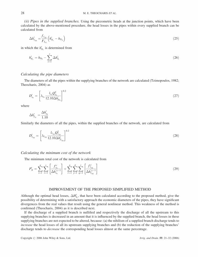
(ii) Pipes in the supplied branches. Using the piezometric heads at the junction points, which have been
calculated by the above-mentioned procedure, the head losses in the pipes within every supplied branch can be
calculated from
�h0‘rjq ¼f ‘rjq
FLrj
h0Nr� hNrj
� �ð25Þ
in which the h0Nris determined from
h0Nr¼ hN0
�Xri¼1
�h0Si ð26Þ
Calculating the pipe diameters
The diameters of all the pipes within the supplying branches of the network are calculated (Tzimopoulos, 1982;
Theocharis, 2004) as
D0sit¼ �sit
lsitQ2sit
12:10�h0fsit
" #0:2
ð27Þ
where
�h0fsit¼
�h0sit1:10
Similarly the diameters of all the pipes, within the supplied branches of the network, are calculated from
D0‘rjq
¼ �‘rjq
l‘rjqQ2‘rjq
12:10�h0f‘rjq
" #0:2
ð28Þ
Calculating the minimum cost of the network
The minimum total cost of the network is calculated from
P0N ¼
Xni¼1
Xvt¼1
f !sit
�h0!�1sit
" #þXnr¼1
Xpj¼1
Xtq¼1
f !‘rjq
�h0!�1‘rjq
" #ð29Þ
IMPROVEMENT OF THE PROPOSED SIMPLIFIED METHOD
Although the optimal head losses, �H0Si
, that have been calculated according to the proposed method, give the
possibility of determining with a satisfactory approach the economic diameters of the pipes, they have significant
divergences from the real values that result using the general nonlinear method. This weakness of the method is
confirmed (Theocharis, 2004) as it is described next.
If the discharge of a supplied branch is nullified and respectively the discharge of all the upstream to this
supplying branches is decreased in an amount that it is influenced by the supplied branch, the head losses in these
supplying branches are not expected to be altered, because: (a) the nihilism of a supplied branch discharge tends to
increase the head losses of all its upstream supplying branches and (b) the reduction of the supplying branches’
discharge tends to decrease the corresponding head losses almost at the same percentage.
28 M. E. THEOCHARIS ET AL.
Copyright # 2006 John Wiley & Sons, Ltd. Irrig. and Drain. 55: 21–32 (2006)

Consequently, if the discharge of all the supplied branches, except the supplied branch of the complete route
presenting the minimum average gradient, is set to zero and the discharge of the supplying branches is replaced at
the same time by the value of the discharge that would result in the case that the supplied branches have been
neglected, the resulting �H0Si
are not expected to differ from the corresponding �HSi . After these, for the
calculation of �H0Si
a network has to be created, which would be similar to the real one. In this network FSi are
substituted by F0Si which are calculated if the discharge of all the supplied branches is nullified except the one that
belongs to the complete route presenting the minimal average gradient.
Thus, the result from the system of nþ k nonlinear equations is
F0Si
�H0Si
" #!¼
FLrj
�H0Lrjq
" #!ð30Þ
and
�H0Lrj
¼ ðhN0� hNrjÞ �
Xri¼1
�H0Si
ð31Þ
from the solution of which (Tzimopoulos, 1982; Theocharis, 2004) �H0Si
are resulted.
�H0Si¼
F0SiPr
i¼1 F0Sii
þ FLrj
ðhN0� hNrj
Þ ð32Þ
Figure 4. The real network under solution
DESIGN OF OPTIMAL IRRIGATION NETWORKS 29
Copyright # 2006 John Wiley & Sons, Ltd. Irrig. and Drain. 55: 21–32 (2006)

From the �H0Si
and �H0Lrj
, the head losses �h0sit and �h0‘rjq of all the pipes which belong to the complete route,
hN0�hNrj are calculated. Using the �h0sit and �h0‘rjq and the real discharges of the pipes, the diameters of the pipes
within the complete route hN0�hNrj
, are calculated. The piezometric heads at the junction points, which have been
calculated by the above-mentioned procedure, are used as heads of the supplied branches of the network; the head
losses and then the diameters of the pipes for all the next supplied branches are calculated.
APPLICATION
Figure 4 shows a network under solution with hN0¼ 89:30 m. The material of the pipes is PVC 10 atm. Figures 4
and 5 represent the real and ideal networks and provide geometric and hydraulic details.
Solving the problem using the general nonlinear programming method
The complete route of the network presenting the minimum average gradient is N0�N51. For N0 ¼ 89:30 m the
minimum average gradient is SmN51¼ 0:5397% and the initial values of first approximation are: �HN1
¼ 0:27 m,
�HN2¼ 1:08 m, �HN3
¼ 0:65 m, �HN4¼ 1:00 m, �HN5
¼ 1:03 m, �HL11¼ 12:63 m, �HL12
¼ 14:93 m,
�HL21¼ 10:05 m, �HL22
¼ 13:35 m, �HL31¼ 8:70 m, �HL32
¼ 11:75 m, �HL41¼ 6:80 m, �HL42
¼ 9:50 m,
�HL51¼ 4:48 m, �HL52
¼ 8:08 m.
Applying the secant method for the ideal network, after the 15th iteration the values of �HSi are reached and
then the values of the piezometric heads HSi are calculated as shown in Table I.
Solving the problem using the simplified method and the improved simplified method
Applying both the simplified and the improved simplified method for the complete route presenting the
minimum average gradient, the values of �H0Si
are calculated and then the values of the piezometric heads, H0i , as
shown in Table I.
12 L12 l =1195 m L11 l =770 m 12
h12=74.10 m h12=76.
=
40 m
22 L22 l =1175 m L21 l = 670 m 21
h22=74.60 m h21=77.90 m
32 L32 l =1000 m L31 l = 970 m 31
h32=75.55 m h31=78.60 m
42 L32 l =810 m L41 l = 915 m 41
h42=76.80 m h41=79.50 m
52 L52 l =810 m L51 l = 830 m 51
h52=76.80 m h51=80.80 m
N
0
S 1
N1
S 2
N2
S3
N
3 S
4
N4
S 5 N N
N
N
N
N
5
l 1=5
0 m
l 2=2
00 m
l 3 =
120
m
l 4 =
185
m l
5=19
0 m
m30.89h0N
N
N
N
N
N
Figure 5. The ideal network under solution
30 M. E. THEOCHARIS ET AL.
Copyright # 2006 John Wiley & Sons, Ltd. Irrig. and Drain. 55: 21–32 (2006)

Selecting the economic diameters of the pipes
Using the piezometric heads at the junction points, as they have been calculated before with the three methods,
as heads of the supplied branches of the network, the frictional head losses as well as the diameters of the pipes
within the other supplied branches are calculated. The results are shown in Table II. From the table and using
Mandry’s cost function, the total cost of the network is calculated by the three methods as following: (a) according
to the general method: PN¼s 295 108; (b) according to the simplified method: PN¼s 300 887; and (c) according
to the improved simplified method: PN¼s 295 173.
Comparing the above costs, it is concluded that (a) the total cost resulting from the simplified method differs
from the cost of the general method by 1.958%; (b) the total cost resulting from the improved simplified method
differs from the cost of the basic method by only 0.022%.
Table I. Values of �Hi and Hi according to the general and to the proposed method
Branch General method Simplified method Improved simplified method
�Hi (m) Hi (m) �H0i (m) H0
i (m) �H0i (m) H0
i (m)
S1 0.31 88.99 0.54 88.76 0.31 88.99S2 1.22 87.77 1.97 86.79 1.25 87.74S3 0.73 87.04 1.04 85.75 0.75 86.99S4 1.13 85.91 1.31 84.44 1.16 85.83S5 1.32 84.59 1.10 83.34 1.19 84.64
Table II. Final values of �hi and Di according to the general and the proposed method
Pipe General Simplified Improved Pipe General Simplified Improvedmethod method simplified method method simplified
method method
�hrjq Drjq �h0rjq D0rjq �h0rjq D0
rjq �hrjq Drjq �h0rjq D0rjq �h0rjq D0
rjq
(m) (mm) (m) (mm) (m) (mm) (m) (mm) (m) (mm) (m) (mm)
s11 0.31 425 0.54 380 0.31 424 l314 1.39 123 1.21 126 1.42 122l111 3.14 141 3.03 142 3.09 141 l321 1.89 183 1.66 188 1.86 184l112 5.06 126 4.95 127 5.04 126 l322 3.23 172 2.84 177 3.18 173l113 4.39 104 4.38 105 4.46 104 l323 2.77 159 2.46 163 2.76 160l121 2.06 193 2.00 194 2.03 194 l324 2.48 143 2.22 146 2.50 143l122 3.67 184 3.58 185 3.63 184 l325 1.11 118 1.02 120 1.14 118l123 3.33 173 3.26 174 3.32 173 s41 1.13 309 1.31 299 1.16 307l124 2.74 160 2.71 160 2.75 160 l411 1.75 186 1.33 197 1.71 187l125 2.02 143 2.02 143 2.05 143 l412 1.95 172 1.49 182 1.92 173l126 1.07 119 1.09 118 1.11 118 l413 1.54 154 1.19 163 1.53 155s21 1.22 395 1.97 359 1.25 393 l421 1.16 128 0.92 134 1.18 128l211 2.63 145 2.34 148 2.59 145 l422 1.93 169 1.59 176 1.89 170l212 4.56 130 4.10 133 4.54 130 l423 2.99 156 2.48 162 2.94 157l213 2.67 107 2.45 109 2.71 107 l424 2.52 140 2.12 145 2.51 140l221 1.85 197 1.68 201 1.81 198 l425 1.67 116 1.44 120 1.70 116l222 3.28 188 3.01 191 3.24 188 s51 1.32 258 1.10 267 1.19 263l223 2.92 177 2.69 180 2.90 177 l511 0.78 203 0.51 220 0.78 203l224 2.45 163 2.28 166 2.46 163 l512 1.29 187 0.85 204 1.30 187l225 1.81 146 1.70 148 1.83 146 l513 1.04 168 0.70 182 1.06 167l226 0.87 121 0.83 122 0.90 120 l514 0.68 139 0.46 150 0.71 138s31 0.73 360 1.05 336 0.75 358 l521 1.42 178 1.15 186 1.40 179l311 2.66 179 2.22 186 2.61 180 l522 2.43 165 2.00 172 2.43 165l312 2.38 166 2.01 171 2.36 166 l523 1.84 148 1.53 153 1.86 147l313 2.00 148 1.71 153 2.01 148 l524 1.70 123 1.45 127 1.76 122
DESIGN OF OPTIMAL IRRIGATION NETWORKS 31
Copyright # 2006 John Wiley & Sons, Ltd. Irrig. and Drain. 55: 21–32 (2006)

CONCLUSIONS
The results of the proposed simplified method and especially those of the improved method are fully identical with
the results of the nonlinear programming method. The calculating procedure required for the determination of the
available piezometric losses is much shorter when using the simplified method than when using the general one—
in the first case k independent linear equations have to be resolved, while in the other there is a system of nþ k
nonlinear equations. Therefore the proposed simplified method is indeed very simple to handle and for practical
uses it requires only a handheld calculator and just a few numerical calculations. Consequently, the simplified
method can be equally used for the classical method.
REFERENCES
Chiplunkar AV, Khanna P. 1983. Optimal design of branched water supply networks. Journal of Environmental Engineering Division, ASCE
109(3): 604–618.
Mandry JE. 1967. Design of pipe distribution for sprinkler and drainage. Journal of the Irrigation and Drainage Division, ASCE 93.
Noutsopoulos G. 1969. The economic piezometric line in gravity pipe distribution systems. Journal of Technika Chronika., Athens 1969(10):
661–676 (in Greek).
Swamee P, Kumar V, Khanna P. 1973. Optimization of dead end water distribution mains. Journal of Environmental Engineering Division,
ASCE 99(2): 123–134.
Swamee P, Khanna P. 1974. Equivalent pipe methods for optimizing water networks—facts and fallacies. Journal of Environmental
Engineering Division, ASCE 100(1): 93–99.
Theocharis M. 2004. Irrigation networks optimization. Economic diameter selection, PhD. thesis, Dept of Rural and Surveying Engineering,
A.U.TH., Salonika (in Greek with extended summary in English).
Tzimopoulos C. 1982. Agricultural Hydraulics. Vol. II, 51-94, A.U.TH., Salonika (in Greek).
Vamvakeridou-Lyroudia LS. 1990. Pressure water supply-irrigation networks. Solution-Optimization. Hydraulics Engineering Computer
Applications, Athens (in Greek).
Watanatada T. 1973. Least cost design of water distribution systems. Journal of the Hydraulics Division, ASCE 99(9): 1497–1513.
32 M. E. THEOCHARIS ET AL.
Copyright # 2006 John Wiley & Sons, Ltd. Irrig. and Drain. 55: 21–32 (2006)
Copyright © 2022 FDOKUMEN