Design of an ultrashort optical transmission cell for vacuum ultraviolet spectroscopy of...
9
Design of an ultrashort optical transmission cell for vacuum ultraviolet spectroscopy of supercritical fluids Ireneusz Janik and Timothy W. Marin Citation: Review of Scientific Instruments 86, 015102 (2015); doi: 10.1063/1.4904874 View online: http://dx.doi.org/10.1063/1.4904874 View Table of Contents: http://scitation.aip.org/content/aip/journal/rsi/86/1?ver=pdfcov Published by the AIP Publishing Articles you may be interested in Multichannel photodiode detector for ultrafast optical spectroscopy Rev. Sci. Instrum. 85, 123111 (2014); 10.1063/1.4903871 Broadband ultraviolet-visible transient absorption spectroscopy in the nanosecond to microsecond time domain with sub-nanosecond time resolution Rev. Sci. Instrum. 84, 073107 (2013); 10.1063/1.4812705 Time resolved metal line profile by near-ultraviolet tunable diode laser absorption spectroscopy J. Appl. Phys. 109, 053307 (2011); 10.1063/1.3553395 High-temperature and high-pressure cell for kinetic measurements of supercritical fluids reactions with the use of ultraviolet-visible spectroscopy Rev. Sci. Instrum. 74, 3073 (2003); 10.1063/1.1573747 A high pressure fiber-optic reactor with charge-coupled device array ultraviolet-visible spectrometer for monitoring chemical processes in supercritical fluids Rev. Sci. Instrum. 70, 4661 (1999); 10.1063/1.1150129 This article is copyrighted as indicated in the article. Reuse of AIP content is subject to the terms at: http://scitationnew.aip.org/termsconditions. Downloaded to IP: 129.74.250.206 On: Wed, 11 Feb 2015 14:51:04
-
Upload
independent -
Category
Documents
-
view
0 -
download
0
Transcript of Design of an ultrashort optical transmission cell for vacuum ultraviolet spectroscopy of...
Design of an ultrashort optical transmission cell for vacuum ultraviolet spectroscopyof supercritical fluidsIreneusz Janik and Timothy W. Marin Citation: Review of Scientific Instruments 86, 015102 (2015); doi: 10.1063/1.4904874 View online: http://dx.doi.org/10.1063/1.4904874 View Table of Contents: http://scitation.aip.org/content/aip/journal/rsi/86/1?ver=pdfcov Published by the AIP Publishing Articles you may be interested in Multichannel photodiode detector for ultrafast optical spectroscopy Rev. Sci. Instrum. 85, 123111 (2014); 10.1063/1.4903871 Broadband ultraviolet-visible transient absorption spectroscopy in the nanosecond to microsecond timedomain with sub-nanosecond time resolution Rev. Sci. Instrum. 84, 073107 (2013); 10.1063/1.4812705 Time resolved metal line profile by near-ultraviolet tunable diode laser absorption spectroscopy J. Appl. Phys. 109, 053307 (2011); 10.1063/1.3553395 High-temperature and high-pressure cell for kinetic measurements of supercritical fluids reactions with theuse of ultraviolet-visible spectroscopy Rev. Sci. Instrum. 74, 3073 (2003); 10.1063/1.1573747 A high pressure fiber-optic reactor with charge-coupled device array ultraviolet-visible spectrometer formonitoring chemical processes in supercritical fluids Rev. Sci. Instrum. 70, 4661 (1999); 10.1063/1.1150129
This article is copyrighted as indicated in the article. Reuse of AIP content is subject to the terms at: http://scitationnew.aip.org/termsconditions. Downloaded to IP:
129.74.250.206 On: Wed, 11 Feb 2015 14:51:04

REVIEW OF SCIENTIFIC INSTRUMENTS 86, 015102 (2015)
Design of an ultrashort optical transmission cell for vacuum ultravioletspectroscopy of supercritical fluids
Ireneusz Janik1,a) and Timothy W. Marin2,b)1Radiation Laboratory, University of Notre Dame, Notre Dame, Indiana 46556, USA2Chemistry Department, Benedictine University, Lisle, Illinois 60532, USA
(Received 24 October 2014; accepted 9 December 2014; published online 5 January 2015)
We present the design and characteristics of an ultrathin flow cell optimized for vacuum ultraviolettransmission spectroscopy experiments on supercritical fluids. The cell operates satisfactorily atpressures up to 300 bar and temperatures up to 390 ◦C. The variable path length concept of thecell allows for optical transmission studies of analytes ranging from dense condensed-phase systemsto gas-phase systems. The path length of the cell can be adjusted from hundreds of nanometers tohundreds of micrometers by an exchange of a variable thickness spacer sandwiched between twosapphire windows. In the path length range from nanometers to single micrometers, metal vapordeposited on one or both of the two sandwiched optical windows constitute the spacer. Spacerswith thicknesses of 2 µm and greater can be constructed from simple commercially available metalfoils. The cell has been used to measure the lowest-lying absorption band of water in both the vaporand condensed phases from room temperature up to and above the critical point. It has also foundapplication in the studies of aqueous ions and nonaqueous liquids including various common organicsolvents and carbon dioxide. C 2015 AIP Publishing LLC. [http://dx.doi.org/10.1063/1.4904874]
I. INTRODUCTION
The measurement of vacuum ultraviolet (VUV) trans-mission spectra in the condensed phase is not a trivial matter,and such measurements have been subjected to a numberof inherent practical experimental limitations.1 The taskbecomes even more challenging when the sample to be studiedmandates elevated pressure and/or temperature (pT) condi-tions. Among various condensed-phase substances whoseVUV optical properties demonstrate significant changes asa function of pT, water seems to be the most challengingfrom an experimental perspective. The critical temperatureand pressure of light water (H2O) are Tc = 370.74 ◦C andpc= 216.59 bar, respectively.2 Compared to other molecularfluids, these values rank among highest documented criticalpoints.2 Considering the intriguing chemical and physicalproperties of water and the known impact of pT variationson its electronic states, we designed a sample cell capableof withstanding broad pressure and temperature tunability toinvestigate the lowest-lying absorption band of H2O fromroom temperature up to its critical point, and over a widerange of densities in the vicinity of the critical point.
This article describes the main characteristics of thisconcept cell. Its ultrashort but changeable path length allowsfor studies of other supercritical fluids as well and becomesespecially useful for the demonstration of pressure variabilityon the nature of excited electronic states. Aside from pressureeffects previously demonstrated for many compounds viathe addition of inert gases like N2, He, or CH4,3 the effectof density on the nature of excited states has not yet been
a)Email address: [email protected])Email address: [email protected]
extensively investigated. To our knowledge, the only opticalmeasurements of high-temperature water were carried upto 70 ◦C and pressures around 5 bar by an attenuated totalreflection method.4 In the design of the cell presented inthis article, attention has been paid to the high working tem-peratures necessary for experiments on supercritical water(SCW), which cause significant differential expansionbetween the metal cell parts and the sapphire window material,and which if unaddressed could dramatically reduce itssealing effectiveness. The high working temperatures and thecorrosive properties of SCW prevent application of typicalvacuum seal materials like fluoroelastomers (e.g., Teflon,Viton, etc.) or soft metals (indium, lead, etc.).
The most important technical constraints for the celldesign are listed in Sec. II. The cell and its operating conditionsare described in detail in Secs. III and IV. Finally, in Sec. V,typical absorption spectra of light water as a function oftemperature and pressure are presented, as obtained in thesubcritical and supercritical domain along its critical isochor.Absorption spectra for selected other systems are presented inSec. VI, demonstrating the broad applicability of this samplecell design.
II. TECHNICAL CONSTRAINS FOR A CELLOPERATING AT HIGH TEMPERATURE ANDELEVATED PRESSURE
Choosing a window material for the cell requirescareful consideration, as the cell design must satisfy sev-eral experimental constraints. High operating temperaturestypically negatively affect the mechanical properties of allwindow materials (increasing their mechanical flexibility anddecreasing their stiffness), leading to enhanced deformation
0034-6748/2015/86(1)/015102/8/$30.00 86, 015102-1 © 2015 AIP Publishing LLC This article is copyrighted as indicated in the article. Reuse of AIP content is subject to the terms at: http://scitationnew.aip.org/termsconditions. Downloaded to IP:
129.74.250.206 On: Wed, 11 Feb 2015 14:51:04
015102-2 I. Janik and T. W. Marin Rev. Sci. Instrum. 86, 015102 (2015)
effects caused by the elevated applied pressure of the sampleinside. The exposed, accessible optical aperture of the cellwindows must be large enough to allow preservation of theoptical source throughput over a sufficiently large wavelengthrange. At the same time, the optical aperture cannot betoo large in order to avoid physical deformation of thewindows due to elevated pressures inside the cell. Sincethe cell described herein was initially intended to studywater and aqueous solutions in the vicinity of the criticalpoint, it is required withstand pressures up to 300 bar andtemperatures up to 390 ◦C, and must be resistant to thehighly corrosive nature of SCW. Due to the relatively highenergy of VUV photons and their capability of inducingphotochemical degradation of the sample, a flow option mustbe accommodated for easy replenishment of the studied fluids.Furthermore, the windows need to be transparent in the VUVregion with transmission extending as low in wavelength rangeas possible. Considering the nature of VUV experiments ingeneral, the cell must be mountable in a vacuum chamber fortypical use with a synchrotron light source and beam line.
Given the relatively small variety of materials with a widetransmission in the VUV range and considerable enoughstrength to sustain excessive loads, only the best qualitysapphire can perform well enough to meet the demandsof SCW experiments. To achieve the largest experimentallyaccessible wavelength range, one must minimize the thicknessof the windows so that the overlap of the sapphire Fermiband edge absorption5 with the measured sample absorptionis suppressed as much as possible. The cell body mustthus be relatively thin and easy to position in front ofthe entrance window of the vacuum chamber containingthe detector. Among various corrosion-resistant materialswhich can withstand high pressures, monocrystalline syntheticsapphire is most appropriate, and this material also hasthe great advantage of being transparent to visible light,making for convenient geometrical alignment with the opticalbeam when exposed to zero-order light from the beam linemonochromator. The sample path length is chosen dependingon the combined transmittance of the windows and sample.As usual in VUV experiments, the high extinction samplemust form a very thin film between the cell windows in orderto transmit a statistically meaningful amount of measurablephotons.
III. CELL CONSTRUCTION AND CHARACTERISTICS
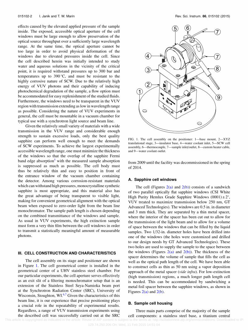
The cell assembly on its stage and positioner are shownin Figure 1. The cell geometrical center is installed in thegeometrical center of a UHV stainless steel chamber. Forour particular experiments, the cell aperture serves effectivelyas an exit slit of a filtering monochromator setup that is anextension of the Stainless Steel Seya-Namioka beam portat the Synchrotron Radiation Center (SRC), University ofWisconsin, Stoughton, WI.6,7 Given the characteristics of thisbeam line, it is our experience that precise positioning playsa crucial role in the repeatability of experimental results.Regardless, a range of VUV transmission experiments usingthe described cell was successfully carried out at the SRC
FIG. 1. The cell assembly on the positioner: 1—base mount, 2—XYZtranslational stage, 3—insulator base, 4—water coolant inlet, 5—SCW cellassembly, 6—thermocouple, 7—sample inlet/outlet, 8—custom heater cable,and 9—water coolant outlet.
from 2009 until the facility was decommissioned in the springof 2014.
A. Sapphire cell windows
The cell (Figures 2(a) and 2(b)) consists of a sandwichof two parallel optically flat sapphire windows (CSI WhiteHigh Purity Hemlux Grade Sapphire Windows (0001)±2◦,VUV treated to maximize transmission below 250 nm, GTAdvanced Technologies). The windows are 0.5 in. in diameterand 3 mm thick. They are separated by a thin metal spacer,where the interior of the spacer has been cut out to allow forthe transmission of the light beam and to allow for a volumeof space between the windows that can be filled by the liquidsamples. Two 1/32-in. diameter holes have been drilled intoone of the windows (the holes were customized and drilledto our design needs by GT Advanced Technologies). Thesetwo holes are used to supply the sample to the space betweenthe windows (Figures 2(a) and 2(b)). The thickness of thespacer determines the volume of sample that fills the cell aswell as the optical path length of the cell. We have been ableto construct cells as thin as 50 nm using a vapor depositionapproach of the metal spacer (vide infra). For low-extinction(high transmission) regions, a much longer path length cellis needed. This can be accommodated by sandwiching ametal foil spacer between the sapphire windows, as shown inFigures 2(a) and 2(b).
B. Sample cell housing
Three main parts comprise of the majority of the samplecell components: a stainless steel base, a titanium central
This article is copyrighted as indicated in the article. Reuse of AIP content is subject to the terms at: http://scitationnew.aip.org/termsconditions. Downloaded to IP:
129.74.250.206 On: Wed, 11 Feb 2015 14:51:04

015102-3 I. Janik and T. W. Marin Rev. Sci. Instrum. 86, 015102 (2015)
FIG. 2. (a) Cross section of the cell assembly in the plane of light path axis and fluid supply lines. (b) View of the VUV transmission cell, disassembled alongthe optical axis: 1—titanium cell body, 2—stainless steel base, 3—locking/supporting posts, 4—inlet/outlet 1/16-in. stainless steel tubing, 5—thermocouple,6—heater cable, 7—gold seal, 8—customized sapphire window with two drilled 1/32-in. through holes, 9—metal spacer (or metal deposition), 10—sapphirewindow, 11—gold spacer, 12—stainless steel concentric spacer, 13—Belleville spring washers, 14—spacer/Belleville washer housing, and 15—stainless steellocking cap.
housing, and a stainless steel end cap. The sapphire windowsare sandwiched inside the central tubular body machined toa custom shape from titanium (Figure 2(b)). The choice ofthis metal, as well as the relatively small body dimensions,was dictated by the need to minimize the longitudinal thermalexpansion of the central part of the cell housing upon heating.The high yield strength of titanium is sufficient to sustain thestress incurred during assembly of the cell prior to samplefilling and operation at the highest desired temperatures. Thecentral part of the housing serves several functions in theoverall cell design. Foremost among these functions is thatit serves as a foundation that holds the front and back cellparts together, allowing for a controlled compression of thesandwiched sapphire windows during assembly. The frontoutside cylindrical surface of the central housing is threadedfor a matching stainless steel cap, which is tightened to thedesired torque using a torque wrench in order to compressthe interior cell parts, to seal the cell windows against themetal spacer between them, and to press and seal the drilledoptical window against the flat stainless steel base of thecell. Two parallel secant holes are drilled through the backoutside cylindrical surface of the main cell housing. Stainlesssteel rods inserted through these holes serve to constrain thestainless steel base coaxial with the titanium body. Clearancethrough holes for Velco 1/16-in. tubing fitting nuts lie betweenthe secant holes, and allow plumbing access to the stainlesssteel base. Note that the back external portion of the cellbase has two parallel flat surfaces that come in handy forsecuring the cell assembly in a vise for convenient assembly.There is a helical groove along the outer part of the centralcell housing which serves to seat a matching wrapped helicalelectrical heating cable. The stainless steel base contains two1/16-in. channels for fluid input/output that are machined toaccommodate 1/16-in. Velco fittings (nut and compressionferrules). The same type of port is machined on the back
of the stainless steel base coaxial to a 1/16-in. throughhole, accommodating a thermocouple which, upon insertion,extends to the front surface of the base. The front surface ofthe stainless steel base is polished to an optical finish, as such afinish was proven necessary in order to accomplish a leak-freeseal between the drilled sapphire window and the stainlesssteel base front surface when operating at high experimentalpressures and temperatures. The compression load of thesandwiched sapphire cell is accomplished by torquing thefront stainless steel cap and transferring the load through theseries of spacing elements (Figures 2(a) and 2(b)). In order toavoid turning of the sapphire cell windows relative to the restof the cell during assembly, a locking spacer (Figure 2(b), 14)is used. The load of the torqued stainless steel cap is appliedthrough the locking spacer to a series of four Belleville springwashers that evenly distribute the load against a cylindricalstainless steel secondary spacer. The outside groove of thesecondary spacer together with the inside groove of thelocking spacer helps to align all the elements along the opticalaxis of the cell. Additionally, a 0.5-mm gold washer is used toease the contact stress between the sapphire window surfaceand the secondary stainless steel compression loading spacer.It is worthwhile to note that the choice of different metalsin the cell housing serves an important practical role. Useof a stainless steel end cap and base prevents gumming ofthe parts (especially the end cap threads) against the titaniumcentral housing when subjected to elevated temperatures undervacuum. Using compression spacers consisting of materialswith higher thermal expansion properties than the outertubular titanium body minimizes the extent of the thermalexpansion gap between the sapphire and metal components.Use of four Belleville spring washers allows compensationfor inevitable mismatches in our thermal element expansionestimates (matched to the best of our abilities based onliterature values but not necessarily reflecting values for
This article is copyrighted as indicated in the article. Reuse of AIP content is subject to the terms at: http://scitationnew.aip.org/termsconditions. Downloaded to IP:
129.74.250.206 On: Wed, 11 Feb 2015 14:51:04

015102-4 I. Janik and T. W. Marin Rev. Sci. Instrum. 86, 015102 (2015)
commercial alloys used in the cell assembly). In addition,the Belleville spring washers assure a steady torque load inspite of the gap created by creep of the gold washer andspacers upon heating under pressure, which are considerableespecially at the highest cell operating temperatures.
C. Cell heating and temperature control
Heat is delivered to the cell by direct contact with acustom-ordered cable heater (50 W, 120 V, sheath diameter0.094 in., ASH Equipment Company) that is wrapped aroundan aluminum heater seat and clamped around the maintitanium cell housing. The length and the diameter of theheater (15 in. and 0.094 in., respectively), were chosen withthe goal in mind to wrap it around the space between the cellend cap and the cell base (Figures 2(a) and 2(b)). The heateris coiled into a helix having a diameter 1/16 in. smaller thanthe heater seat outer diameter so that it serves as an effectivespring, holding itself in place around the heater seat. Theheater seat consists of an aluminum ring into which a helicalprofile matching that of the wrapped heater has been milledon the outer surface. The ring was wire-cut via electricaldischarge machining into two halves which clamp aroundthe cell housing groove (Figures 2(a) and 2(b)) and are heldtogether by the spring force of the coiled heater itself. Duringinitial assembly of the heater components, the cable heater isthreaded into the heater seat groove. Since it has a slightlysmaller diameter than the diameter of the seat, it snugly clampsitself into place. Initially, we incorporated an outer ring aswell with a similar helical groove pattern to keep the heaterfrom loosening over time. However, eventually we found itto be unnecessary in the vacuum chamber since the amountof heating power needed for achieving temperatures up to390 ◦C was very low (less than 20 W), and the clamping forceof the heater maintained desirable thermal contact betweenall of the clamped cell elements over the several year timeperiod during which these experiments were performed. Thecable heater has an exposed 2-in. long nonheating section thatis not coiled over the cell but rather protrudes from the side ofthe cell. This was left in place purposefully to avoid heatingany section of the cable heater that does not have directthermal contact with the cell, which in vacuum may overheatand glow, causing unwanted evaporation of the solderingalloy of the cable heater assembly and additional unwantedbackground light in the sample chamber. The wattage ofthe heater is set by changing the voltage across the heater,as controlled by a programmable DC power supply (XHR100-10 Watt Series, Xantrex). The temperature of the cellis measured using an N-type thermocouple (calibrated vs.RTD Pt) connected to an autotune proportional-integral-derivative (PID) temperature/process controller (CN77000,Omega). During operation, the cell was tightly wrapped withthin kitchen-type aluminum foil to minimize heat loss due toradiation.
D. Sample flow
Figure 3 illustrates the general plumbing layout neededfor filling and flushing the supercritical cell. A syringepump (PHD 2000, Harvard Apparatus) equipped with a
FIG. 3. Schematic representation of the VUV cell plumbing.
high-pressure 2-ml stainless steel syringe is filled witha deaerated (sparged with He gas) sample of interest.The syringe is connected to a custom-made stainless steelcheck valve head which is analogous in operation to headsinstalled on commercially available high-performance liquidchromatography (HPLC) piston pumps, where the sapphirecheck valves have been scavenged from an HPLC pump(Series III, Scientific Systems, Inc.). The check valve systemwas successfully used with a variety of liquids includingaqueous solutions and organic solvents. In experiments withsupercritical CO2, an 8-ml stainless steel syringe was used(Harvard apparatus) instead with two manual valves, andit was connected through a Swagelok 1/8-in. tee. Fluidis delivered from the pump to the cell through 1/16-in.stainless steel tubing. A series of stainless steel manual valves(Figure 3) help to quickly refill or flush the branches ofthe plumbing system. The overall pressure of the samplefluid is set using a back pressure regulator (54-2162T24,Tescom), manually adjusted as necessary for a given flowrate, and monitored by a factory calibrated pressure transducer(PX01D1-5KSV, Omegadyne, Inc.). Since the sample cell andthe plumbing system together comprise a very low volumeflow system, exchange of the sample fluid can easily beperformed when the cell is already at elevated temperature toavoid inconveniently long cooling and heating times betweensample refills or exchanges. Depending on the selected pathlength of the cell, the actual fluid flow through the cellintroduces its own inherent back pressure (due to operationin the microfluidic domain), and hence it also introduces anunwanted pressure gradient inside the cell. In order to avoidthis pressure gradient as well as any unwanted flow turbulence,especially under supercritical conditions, the bypass valve(Figure 3) stays open during spectroscopic measurements.Fluid bypassing the cell flows directly to the back pressureregulator. Any small pressure variations are corrected by anincrease/decrease of the pump rate speed. Typical flow ratesduring experiments are 1-10 µl/min, with higher flow ratesbeing needed for a longer path length sample cell. If needed,software controlling the flow rate of the syringe pump canbe used to continually adjust the back pressure (and hencethe pressure in the sample cell) based on fluctuations of thepressure readout. We found this automatic adjustment to be
This article is copyrighted as indicated in the article. Reuse of AIP content is subject to the terms at: http://scitationnew.aip.org/termsconditions. Downloaded to IP:
129.74.250.206 On: Wed, 11 Feb 2015 14:51:04

015102-5 I. Janik and T. W. Marin Rev. Sci. Instrum. 86, 015102 (2015)
unnecessary, however, because the fluctuations are very smalland slow, and can easily be corrected manually in real time.
E. Positioning of the cell in the vacuum chamber
The sample cell is seated on top of a centrally pivotingtranslation stage (Newport M-DS40-XYZ) located in thegeometrical center of a custom-designed vacuum chamber.A ceramic insulator plate (dense, vacuum tight, machinableRescor™ 914 Glass Ceramic, Cotronics Corp.) is bolted ontop of the translation stage and thermally separates the stagefrom the sample cell. The cell is supported on this plate bythree stainless steel pins. Two of the pins (labeled 3 in Figure2(b)) extending from the cell are inserted into correspondingholes in the insulator plate. A third pin made of 1/8-in.stainless steel rod is permanently mounted in the insulatorbase to provide a third point of support. To assure consistentpositioning of the cell upon adjustment of the translation stageand upon repeated insertion in the insulator plate (which isfrequently necessary after disassembling the cell to change itspath length), a custom spring brace, made of stainless steelwire wrapped over the circumference of the sample cell endcap, presses the cell downwards toward the insulator plate. Aspiral of 1/16-in. stainless tubing is sandwiched between theinsulator plate and the top of the translation stage. Coolingwater is continually circulated through this tubing at a rate of5 ml/min to prevent heat transfer from the sample cell to thetranslation stage and also to serve as a heat sink for the samplecell. This permits PID control of the sample temperature ona reasonable timescale. The cell position is initially manuallyadjusted through the translation stage for optimal transmissionof photon flux at 200 nm in air. After evacuation of the vacuumchamber, the vertical position of the cell can be additionallyoptimized through a rotary manipulator installed on the flangeof the vacuum chamber and attached by flexible couplingsto the translation stage’s vertical and horizontal positioningscrews. The position of the cell on its longitudinal axis wasinitially optimized in air to assure its placement in the waistof the incident zero-order white light beam focus and was notcorrected afterwards since the optical properties or positioningof the beam line were not observed to change over time.
IV. CELL OPERATION
A. Preparation of sapphire-metal seal
The seal between the drilled sapphire window and thestainless steel base of the sample cell is achieved througha 0.5-mm gold foil (Alfa Aesar) gasket. A 0.5-in. diametercircular gasket shape is cut out from a sheet of gold foil using aprecision punch-die set (Precision Brand). A central 1/16-in.hole and two 1/32-in. holes are introduced in the circulargasket using a stainless steel template (Figure 4, which wealso use to prepare our metal foil spacers). The central holeis necessary for light transmission, and the smaller holes arematched to those in the cell base and sapphire window forsample flow into and out of the cell. A precut circular goldgasket is clamped into the 0.5-in. diameter countersink of thetemplate tool, which assures precise transfer of the templateholes to the gold material as well as prevents any unwanted
FIG. 4. Tool for manufacturing gold gasket as well as metal foil windowspacers.
burr formation during the drilling process. After fabrication,the gasket is placed flat against the cell base and initiallycompressed tightly against the cell base with an opposing flatsapphire window, using up to 65 ft pounds of torque on thesample cell end cap. The compressed cell is then installed inthe vacuum chamber and heated up to 400 ◦C under vacuum topermit creep and annealing of the gold seal to give an opticallyflat surface like that of the sapphire window and also to giveadhesion to the cell base. After at least 2 h of annealing,the temperature is lowered to room temperature. The cell isthen removed from the vacuum chamber and recompressedto the same torque load. The cell is then reinserted intothe vacuum chamber. However, this time the flow tubing isconnected in order to check for any leaks around the gasket.Since at this point, the flow holes in the sample cell directonly to a flat window, there should be no flow of fluid ifdelivered either to the inlet or outlet plumbing. Consequently,after achieving high vacuum levels in the vacuum chamber,the tubing is pressurized with water up to 300 bar. Lackof any leaks on either the inlet or outlet side, as indicatedby no change in the vacuum chamber pressure, assures theusability of the prepared gold gasket. The cell can then bedismounted, and the desired set of experimental windowswith desired path length spacers can be inserted. The goldgasket just described can be reused for many experiments. Inour experience, one gasket served for 3 years without needof replacement. In fact, the only reason for the failure of thegasket encountered to date was operator error in accidentallyscratching the optically flat gold gasket surface during cellassembly. As such, care must be taken to avoid any unwantedelements or dust from falling against the gasket during thecell disassembly or reassembly processes. Otherwise, the goldgasket seal adheres strongly to the stainless steel cell base,and during the process of removing the sapphire windows, theseal between the stainless steel base and gold remains intact.
B. Preparation of the window spacers
For cell path lengths smaller than 2 µm, a metal vapordeposition method was used to create the window spacers. Inthis process, the sapphire windows were used as substratesfor direct deposition of a metal film. Prior to deposition, thewindows were baked at 400 ◦C for 3h to remove any organicmaterial. A mask over the cell window surface was applied ina clean room using Kapton tape, to mask an area in the center
This article is copyrighted as indicated in the article. Reuse of AIP content is subject to the terms at: http://scitationnew.aip.org/termsconditions. Downloaded to IP:
129.74.250.206 On: Wed, 11 Feb 2015 14:51:04

015102-6 I. Janik and T. W. Marin Rev. Sci. Instrum. 86, 015102 (2015)
of the window for eventual light transmission. The windowswith masks were then dry etched with oxygen plasma (MS-5,Drytek) for 10 min at an radio frequency power of 1500 W.Metal depositions were thereafter performed in a multisourceelectron-beam evaporator (FC 1800, Temescal). Typically, a10-nm titanium sublayer was deposited first (at a rate of 0.2nm/s) before the actual gold spacer layer was deposited tothe desired thickness (rate, 0.5 nm/s). The thin titanium layerpermits better adherence of the gold to the window material.During metal deposition, the windows were centrally mountedinto a custom-made flat bar, which was placed over the metalsource turret. Usually, 9-12 windows were prepared duringone deposition session. The thickness was monitored with afilm thickness monitor (SQM160, Sigma Instruments). Overthe course of the experiments with SCW, we experiencedsubstantial creep of the gold spacers, resulting in a gradualdecrease of the film thickness over several hours and hencea decrease in the cell path length and an increase of thelight transmission through the cell. This effect was morepronounced in the thinnest cells used. In order to limit thiseffect for the SCW experiments, we increased the thickness ofthe titanium sub-layer to comprise 50% of the total depositionthickness.
It is worthwhile to note that we successfully preparedultrathin path cells in cases when either just one or both of thecell windows had gold deposited upon them. In cases whereonly one window received a deposition and other did not, itwas challenging to obtain leak free cells at higher pressures.This almost certainly had something to do with the polishingquality of the windows. In cases where both windows receiveda metal deposition, the windows welded together after beingexposed to high pressure and temperature, thus creatingessentially one entity that could be stored and reused at latertimes if needed. However, we found it necessary in practiceto reuse the same windows over and over again for the sake ofoptical consistency, so that the window transmission stayedconsistent regardless of the sample cell path. Accordingly, weroutinely dissolved the metal from fused cells using baths ofaqua regia and HCl in order to recover the windows for reusewith thicker spacers.
To obtain spacers of 2 µm and thicker, we used a varietyof thin metal foils. Titanium, chromium, and gold foils withthicknesses up to 500 µm (Alfa Aesar) were successfully used.In experiments with supercritical methanol, we attempted touse aluminum foil (0.8 µm, Alfa Aesar) only to learn that itundergoes dissolution under supercritical conditions. We didnot explore the reasons for this peculiar effect and deemed itbeyond the scope of this work. The procedure for preparingthe thin metal spacers was analogous to the preparation ofthe gold gasket seals described in Sec. IV A. The metal foilwas cut into a 0.5-in. circle using a precision punch-die set.In order to prevent the delicate thin foils from tearing, thematerial was sandwiched and punched between two celluloidfilms. After being punched, the foil was handled between thecomplementary punched celluloid circles. The metal foil circlesandwiched between the two 0.5-in. celluloid circles was theninserted into the 0.5-in. diameter countersink in our customtemplate tool (Figure 4), which allowed precise drilling ofa central 1/16-in. hole necessary for light transmission and
two 1/32-in. holes needed for the inlet and outlet sampleflows. Such a manufactured spacer was then placed into atightly sealed plastic bag (made using a plastic film sealer),with the bag surfaces lying tightly against the metal foil toprevent it from bending during storage or transport. Just priorto experiments, a scalpel blade was used to manually cutthrough the plastic and foil material to remove the materialbetween the 1/32-in. holes and through the 1/16-in. hole,creating a flow path between the inlet/outlet sample flowholes and across the entirety of the perpendicular optical lightpath.
C. Mechanical limitations of the cell windows underhigh pressure
Transmission experiments using submicron sample pathlengths proved to be quite challenging. In our initialstudies, we learned that small bending deflections in the cellwindows under pressure contributed considerably in alteringthe cell path length as a function of pT, hence affectingthe correct estimation of the actual sample absorbance.Upon a pressure increase, the sample absorbance did notincrease proportionally to its known increase in density(concentration) as predicted from the water equation of state.These measurements were performed with a cell consistingof two 1.5-mm thick sapphire windows and with a 3-mmoptical aperture in the cell, i.e., a 3-mm disc of sapphire wasexposed to the vacuum while the remainder of the windowwas pressed against the components of the metal sample cell.Based on the equations for normal deflection of a bar ofmaterial with applied stress on the center point of one side,it is expected that the extent of deflection should be inverselyproportional to the third power of the thickness of the bar(in our case, sapphire), as well as to the third power of thedistance from the points of the bar support (cell aperture).Consequently, we doubled the thickness of the sapphire anddecreased the cell aperture by a factor of two, expecting adecrease of the deflection by a factor of 64. By our estimates,after these changes, the observed deflections should have beennegligible. Yet, we still observed quite a substantial effect fromincreasing the applied pressure, leading to an increase in thecell path length. We concluded that the observed effect musthave been related to the displacement of the surface layers ofsapphire crystal structure under pressure. We illustrated thispurported displacement of the window surface layers at 390 ◦Cas a function of introduced helium gas pressure, as seen inFigure 5. We used the observed Newton interference fringesto estimate the cell path length and its change after an increasein He pressure. The relationship between the thickness l ofthe cell and the number n of interference fringes betweenthe wavelengths λ1 and λ2 is 2l = nλ1λ2/(λ1−λ2). Based onthis relation, we estimated the path length of the cell at 1bar and at 123 bar at 390 ◦C in the range of the highest lighttransmission. In a cell making use of a commercial titanium6-µm foil spacer, we observed 14 fringes which spread over38 nm and 37 nm at 1 bar and 123 bar, which corresponds to5.802 and 5.929 µm, respectively. Therefore, the difference inthe path length was roughly about 127 nm. Hence, each of thewindows displaced about 63.5 nm at 390 ◦C at 123 bar. This
This article is copyrighted as indicated in the article. Reuse of AIP content is subject to the terms at: http://scitationnew.aip.org/termsconditions. Downloaded to IP:
129.74.250.206 On: Wed, 11 Feb 2015 14:51:04

015102-7 I. Janik and T. W. Marin Rev. Sci. Instrum. 86, 015102 (2015)
FIG. 5. Effect of He gas pressure on the deflection of windows at 392.7 ◦C.Vertical lines represent λ1 and λ2, as described in the text.
value doubles at double the pressure. For the path lengths of6 µm and more, this effect would account for less than 2%deviation in the optical path length. But for the shortest pathlengths, this amount of deviation is significant and will causea considerable error in the extinction coefficient estimations(see below). Considering that the Young’s modulus ofsapphire increases substantially with increasing temperature,8
the displacement should become less pronounced at lowertemperatures especially if the sample pressure is lower than100 bar. In fact, in most supercritical fluids, the criticalpoint is below 100 bar 300 ◦C.2 Hence, the described windowdisplacement effect should not be particularly significant formeasurements performed on supercritical fluids other thanwater.
V. VUV TRANSMISSION MEASUREMENTS
After many experiments, it became clear that measure-ments in the ultrashort path cells described above wouldinevitably bear uncertainty concerning their exact pathlengths. Therefore, additional experiments with longer pathlengths starting from as high as 500 µm (where thepercent contribution of the effects described in Sec. IV Care negligible), were performed to serve to anchor the mea-sured extinction coefficients at wavelengths away from theabsorption maxima, where extinction was much lower. Usingthese extinction coefficients as a reference, their data couldbe overlaid with experiments using consecutively shorter pathlengths in adjoining wavelength regions, where extinctioncoefficients are increasing but the absorbance remains similardue to the shorter path length. At the shortest path lengths,where the problems described in Sec. IV C were apparent,the slope of the data (as a function of wavelength) wasmatched with that in adjacent wavelength regions by slightlyscaling the amplitude accordingly to account for the likelypath length uncertainty. This bottom-up approach allowedus not only to build entire absorption spectra over a broadrange of extinction coefficients, but it also helped to eliminateoptical interference fringes in parts of the spectra, where
FIG. 6. VUV spectrum of subcritical light water at 350 ◦C and 190 bar madeby combination of several partial absorption spectra obtained at differentcell path lengths. Extinction coefficients obtained at shorter path lengths arescaled to match the values obtained for the longest path length used.
the transmission was highest and shortest path cells wereused. It was typical that a progression of cell thicknesses wasinvolved in the measurement of VUV absorption spectra insubcritical and supercritical fluids, first using a series of cellsmade with metal foil spacers and then using a series of cellsmade with metal vapor deposited spacers. For example, toassure the correctness of the cell thickness in the measurementof the lowest-lying absorption band of water, the followingcells were progressively used: 500 µm, 50 µm, 6 µm, 2 µm,and a sub-µm deposition, dependent on the density of thefluid (varying from 0.4 to 0.9 µm). The exact thickness ofthe thickest reference spacers applied in transmission mea-surements was carefully measured before and after cellassembly using a precision micrometer screw. In orderto obtain an absorption spectrum (based on Beer–Lambertrelation A=−log(I/I0), where I and I0 are the incident andthe transmitted radiation intensities, respectively), light trans-mission through the empty cell was measured as well using thethickest spacer (∼500µm) installed before filling the cell withsample fluid. Routinely, empty cell spectra were acquiredin the process of sealing the cell, when the long-path cellwas disconnected from the sample flow system but sealedunder vacuum in the vacuum chamber (Sec. IV A). Lightintensities in empty and filled cell transmission measurementswere normalized to the synchrotron beam current, which wasmonitored in real time during data acquisition. Figure 6presents a compilation of typical partial absorption spectrameasured for subcritical water at a pressure of 195 bar.
VI. RESULTS
A series of measurements of VUV absorption spectra insubcritical and supercritical fluids were performed showinga dramatic effect of density on the nature of excited states.Since detailed studies of the obtained data are currently inpreparation, we only briefly present the results here. Figure 7presents the effect of temperature on the charge transfer to
This article is copyrighted as indicated in the article. Reuse of AIP content is subject to the terms at: http://scitationnew.aip.org/termsconditions. Downloaded to IP:
129.74.250.206 On: Wed, 11 Feb 2015 14:51:04
015102-8 I. Janik and T. W. Marin Rev. Sci. Instrum. 86, 015102 (2015)
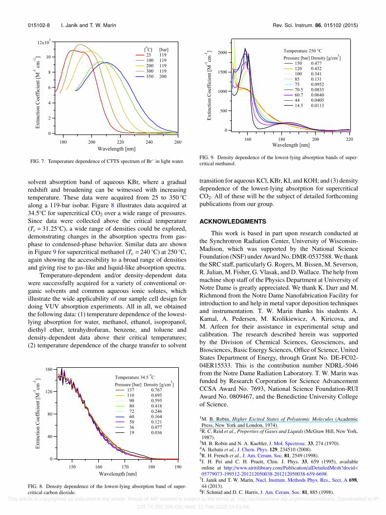
FIG. 7. Temperature dependence of CTTS spectrum of Br− in light water.
solvent absorption band of aqueous KBr, where a gradualredshift and broadening can be witnessed with increasingtemperature. These data were acquired from 25 to 350 ◦Calong a 119-bar isobar. Figure 8 illustrates data acquired at34.5◦C for supercritical CO2 over a wide range of pressures.Since data were collected above the critical temperature(Tc = 31.25◦C), a wide range of densities could be explored,demonstrating changes in the absorption spectra from gas-phase to condensed-phase behavior. Similar data are shownin Figure 9 for supercritical methanol (Tc = 240 ◦C) at 250 ◦C,again showing the accessibility to a broad range of densitiesand giving rise to gas-like and liquid-like absorption spectra.
Temperature-dependent and/or density-dependent datawere successfully acquired for a variety of conventional or-ganic solvents and common aqueous ionic solutes, whichillustrate the wide applicability of our sample cell design fordoing VUV absorption experiments. All in all, we obtainedthe following data: (1) temperature dependence of the lowest-lying absorption for water, methanol, ethanol, isopropanol,diethyl ether, tetrahydrofuran, benzene, and toluene anddensity-dependent data above their critical temperatures;(2) temperature dependence of the charge transfer to solvent
FIG. 8. Density dependence of the lowest-lying absorption band of super-critical carbon dioxide.
FIG. 9. Density dependence of the lowest-lying absorption bands of super-critical methanol.
transition for aqueous KCl, KBr, KI, and KOH; and (3) densitydependence of the lowest-lying absorption for supercriticalCO2. All of these will be the subject of detailed forthcomingpublications from our group.
ACKNOWLEDGMENTS
This work is based in part upon research conducted atthe Synchrotron Radiation Center, University of Wisconsin-Madison, which was supported by the National ScienceFoundation (NSF) under Award No. DMR-0537588. We thankthe SRC staff, particularly G. Rogers, M. Bissen, M. Severson,R. Julian, M. Fisher, G. Vlasak, and D. Wallace. The help frommachine shop staff of the Physics Department at University ofNotre Dame is greatly appreciated. We thank K. Darr and M.Richmond from the Notre Dame Nanofabrication Facility forintroduction to and help in metal vapor deposition techniquesand instrumentation. T. W. Marin thanks his students A.Kamal, A. Pedersen, M. Krolikiewicz, A. Kiricova, andM. Arfeen for their assistance in experimental setup andcalibration. The research described herein was supportedby the Division of Chemical Sciences, Geosciences, andBiosciences, Basic Energy Sciences, Office of Science, UnitedStates Department of Energy, through Grant No. DE-FC02-04ER15533. This is the contribution number NDRL-5046from the Notre Dame Radiation Laboratory. T. W. Marin wasfunded by Research Corporation for Science AdvancementCCSA Award No. 7693, National Science Foundation-RUIAward No. 0809467, and the Benedictine University Collegeof Science.
1M. B. Robin, Higher Excited States of Polyatomic Molecules (AcademicPress, New York and London, 1974).
2R. C. Reid et al., Properties of Gases and Liquids (McGraw Hill, New York,1987).
3M. B. Robin and N. A. Kuebler, J. Mol. Spectrosc. 33, 274 (1970).4A. Ikehata et al., J. Chem. Phys. 129, 234510 (2008).5R. H. French et al., J. Am. Ceram. Soc. 81, 2549 (1998).6J. H. Pei and C. H. Pruett, Chin. J. Phys. 33, 659 (1995), availableonline at http://www.airitilibrary.com/Publication/alDetailedMesh?docid=05779073-199512-201212050038-201212050038-659-669#.
7I. Janik and T. W. Marin, Nucl. Instrum. Methods Phys. Res., Sect. A 698,44 (2013).
8F. Schmid and D. C. Harris, J. Am. Ceram. Soc. 81, 885 (1998). This article is copyrighted as indicated in the article. Reuse of AIP content is subject to the terms at: http://scitationnew.aip.org/termsconditions. Downloaded to IP:
129.74.250.206 On: Wed, 11 Feb 2015 14:51:04