Design of a suspension system for a Formula Student ...
48
Bachelor's Degree Final Project by Mohamed Boutanaach Design of a suspension system for a Formula Student electrical race car European Project Semester (EPS) of 30 ECTS credits submitted to the Faculty for Technology, Innovation & Society at The Hague University of Applied Sciences (Delft, The Netherlands) Bachelor of Science (BSc) in Mechanical engineering 2015-16 Supervisor: Peter Menger, Responsible lecturer Richard Mens, lecturer Coordinators Learning Lab 'Sustainable Mobility', The Hague University of Applied Sciences Examiner: Dr. David Tiemens, Assessor Professor of Mechanical engineering, The Hague University of Applied Sciences Dr. Yuste Pérez Pedro, Mentor Department of Computer Engineering, School of Design Engineering, Polytechnic University of Valencia
-
Upload
khangminh22 -
Category
Documents
-
view
0 -
download
0
Transcript of Design of a suspension system for a Formula Student ...

Bachelor's Degree Final Project
by
Mohamed Boutanaach
Design of a suspension system for a Formula Student
electrical race car
European Project Semester (EPS) of 30 ECTS credits submitted to the Faculty for
Technology, Innovation & Society at The Hague University of Applied Sciences (Delft, The
Netherlands)
Bachelor of Science (BSc) in Mechanical engineering
2015-16
Supervisor:
Peter Menger, Responsible lecturer
Richard Mens, lecturer
Coordinators Learning Lab 'Sustainable Mobility', The Hague University of Applied Sciences
Examiner:
Dr. David Tiemens, Assessor
Professor of Mechanical engineering, The Hague University of Applied Sciences
Dr. Yuste Pérez Pedro, Mentor
Department of Computer Engineering, School of Design Engineering, Polytechnic University of
Valencia
1
Abstract.
The Formula Cruisers is a student project started by The Hague University of Applied Sciences
(Delft, The Netherlands). The purpose of the team is to gain work experience by creating an
electric race car.
Our team consists of students from multiple studies, nationalities and disciplines. The project is
challenging and educational, but enjoyable at the same time.
Currently, the team has students on the team who study Mechanical engineering, Electrical
engineering, Applied physics, Industrial design and Aeronautical engineering.
The aim of our team will be build the HU-2, our first full-electric formula race car. The car will
participate in the Formula Student event in Silverstone (United Kingdom). Formula student,
Europe’s most established educational motor sport competition, was the ultimate goal for The
Formula Cruisers to take part in. Not only the competition between teams is exciting, but the
thrill also comes from designing and building our own electric race car.
The HU-2 has to pass all the technical tests.
Figure 1. HU-2 Race Car. The Hague University of Applied Sciences.
2
Contents 1 CHAPTER 1. Introduction. ..................................................................................................................... 3
Project ........................................................................................................................................................... 4
Learning goals ........................................................................................................................................... 4
Processes in the Learning Labs ..................................................................................................................... 4
Technical Processes .................................................................................................................................. 5
Engineering Process .............................................................................................................................. 5
Support Process ..................................................................................................................................... 5
Management Process ............................................................................................................................ 6
Learning Process ....................................................................................................................................... 6
Main learning process: experienced based learning .............................................................................. 6
Supporting learning processes .............................................................................................................. 7
Additional courses ................................................................................................................................ 8
Students Team. ...................................................................................................................................... 8
Foreign students, international class room, main language .................................................................. 9
Lectures ..................................................................................................................................................... 9
Supporting staff ......................................................................................................................................... 9
Finance and sponsor obligations ................................................................................................................... 9
Deliverables and Assessment ...................................................................................................................... 10
Technical deliverables ............................................................................................................................ 10
Learning outcomes .................................................................................................................................. 11
Assessment .............................................................................................................................................. 11
2 CHAPTER 2. Research. ......................................................................................................................... 13
3 CHAPTER 3. Design process. ............................................................................................................... 20
4 CHAPTER 4. Calculation of the suspension system. ............................................................................ 35
5 CHAPTER 5. Autodesk Inventor 3D MODELS. ..................................................................................... 40
6 CHAPTER 6. Conclusion. ...................................................................................................................... 45
7 CHAPTER 7. References. ...................................................................................................................... 47
3
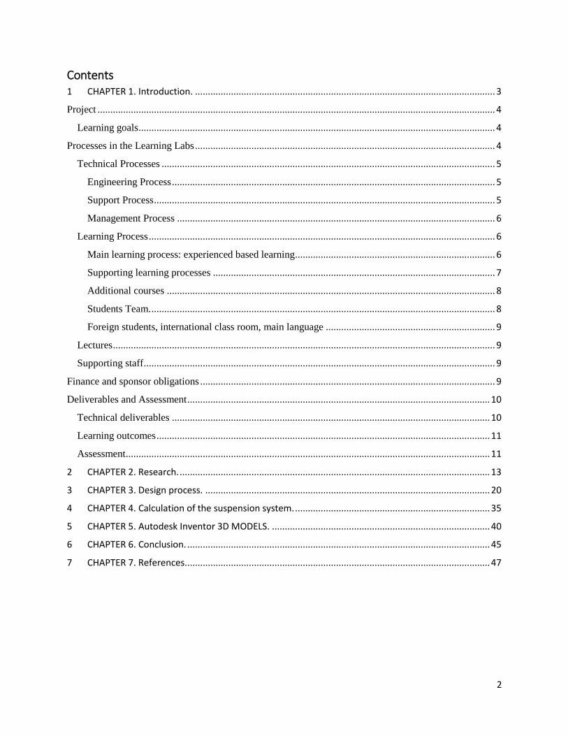
1 CHAPTER 1. INTRODUCTION.
Formula Cruisers Team 2015/16 (Beta factory. THUAS, Delft).
Figure 2. The Formula Cruisers Team. Delft (The Netherlands).
4
Study guide focusses on the projects in the Learning Lab ‘Sustainable Mobility’.
Project
The minor is to be performed in the context of one of the multidisciplinary, multinational,
multilevel engineering projects as carried out in the Learning Labs of the Beta factory of The
Hague University of Applied Sciences in Delft.
Learning goals
After the course the participant is expected to be able to:
1. Technical
1.1. analyse technical problems in a systems view,
1.2. handle technical problems which are incompletely stated and subject to multiple,
contradictory and technical and non-technical constraints,
1.3. develop strategies for systematic choice and use of available engineering methods,
tools and resources,
1.4. make estimations and appreciate their value and limitations,
1.5. communicate engineering – orally, in writing and graphically.
2. Project Management
2.1. Make decisions based on acquired knowledge,
2.2. pursue own ideas and realize them practically,
2.3. assess quality of own work and work by others,
2.4. understand and explain the mechanisms behind progress and difficulties in such a
setting and act accordingly,
2.5. secure knowledge and information.
3. Personal development
3.1. reflect on own performance based on own experiences.
Processes in the Learning Labs
In the Learning Labs projects two main processes are distinguished, i.e. technical processes and
learning processes respectively. All technical processes are directed to specify, design and realise
a technical product. Learning processes concern the individual student.
5
Technical Processes
Engineering Process
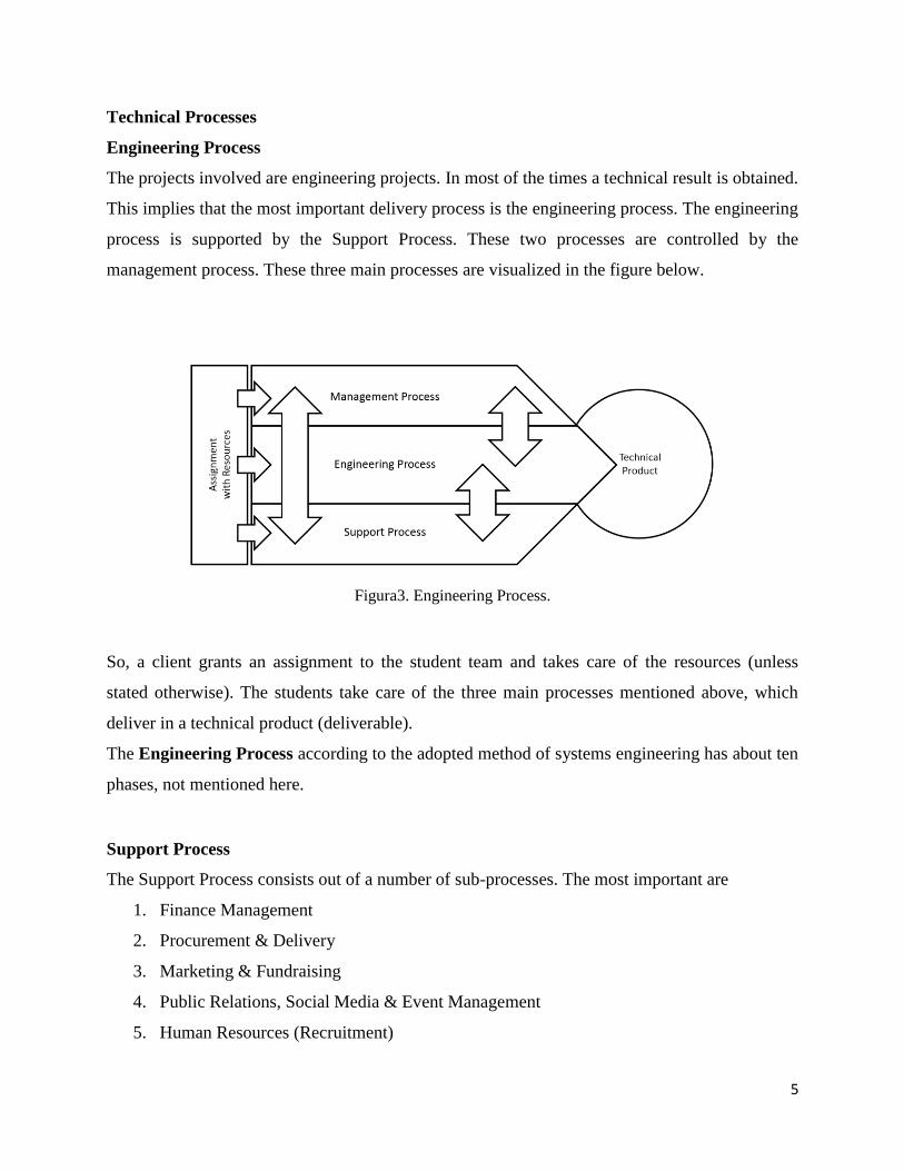
The projects involved are engineering projects. In most of the times a technical result is obtained.
This implies that the most important delivery process is the engineering process. The engineering
process is supported by the Support Process. These two processes are controlled by the
management process. These three main processes are visualized in the figure below.
Figura3. Engineering Process.
So, a client grants an assignment to the student team and takes care of the resources (unless
stated otherwise). The students take care of the three main processes mentioned above, which
deliver in a technical product (deliverable).
The Engineering Process according to the adopted method of systems engineering has about ten
phases, not mentioned here.
Support Process
The Support Process consists out of a number of sub-processes. The most important are
1. Finance Management
2. Procurement & Delivery
3. Marketing & Fundraising
4. Public Relations, Social Media & Event Management
5. Human Resources (Recruitment)

6
Management Process
The Management Process consists of the management of all processes. It can be split up in the
following sub-processes
1. General Management
a. Planning
b. Finance
c. Knowledge, Information
d. Quality
e. Organization
2. Engineering Management
3. Support Management
4. Systems Engineering
Learning Process
The Technical Processes and their environment are the vehicle with which the learning processes
take place.
Main learning process: experienced based learning
Working and learning in the Learning Lab is, just like an internship, a full time job, i.e. eight
hours a day, 40 hours a week. The learning process is embedded in the execution of the project.
It is called ‘experience based learning’. The actions undertaken for the project and their outcome
are input for the lessons on project management, personal development and portfolio building.
The most important micro-process for learning is the feedback process as shown below.
Figure 4. Main learning process.

7
This implies the following. In order for students to learn they should generate output for others,
i.e. fellow team members (peers), lecturers and stakeholders, for them to give feedback on. This
feedback is incorporated in the result obtained so far. Output and feedback are stored in the
portfolio for evidence of the learning process which is used in the assessment.
Figure 5. Feedback.
Supporting learning processes
In addition to the main learning process there are a number of secondary or supporting learning
processes. These are workshops
1) Project Management
2) Personal Development
3) Personal Coaching
Project Management
There are on a weekly basis workshops on project management. In these workshops the
lecturer(s) discuss the issues raised up during project work with the whole team. Students are
responsible for the input of these workshops.

8
Personal Development
In these weekly workshops important themes about project collaboration are dealt with.
Exercises and experiments are carried out on which students reflect on. New insights will arise
from this and results are reported in the process report which again is included in the portfolio.
Personal Coaching
On special request and on a regular basis, e.g. weekly, students make personal appointments with
their guiding expert and/or coach. Personal issues on technical or personal aspects are discussed.
Results are incorporated in the project work, process report and/or portfolio.
Additional courses
Next to the main learning process of experimental learning and its secondary processes there are
a number additional courses on
1) Cultural Differences
2) English Language
3) Project Management (guest lecture(s))
4) Others.
Students Team.
Most students originate from the engineering educations of the faculty of The Hague University
of Applied Sciences in Delft. The following engineering educations contribute mostly to the
engineering process
Mechanical Engineering,
Electronical Engineering,
Mechatronics,
Computer Science,
Technical Physics,
Technical Mathematics,
Students of the education of
Technical Business Management.
can be found in the management.
The supporting processes are taken care by students of the educations of the faculties
9
Communication & Multimedia Design (CMD)
Industrial Design Engineering (IDE)
International Communication Management (ICM)
International Financial Management and Control (IFMC)
If these students are not participating in the project, then the engineering students will have to do
the tasks involved.
Foreign students, international class room, main language
The Hague University of Applied Sciences participates in a number of worldwide coalitions for
student exchange. Students of abroad from equivalent educations mentioned above also
participate in the Learning Lab projects. Therefore the main language in speech and writing is
English.
Therefore the Learning Lab projects have the status of ‘international classroom’. Dutch students
who want to have international experience may participate in the Learning Lab project without
leaving the country.
Lectures
Students are guided and coached by lectures on engineering disciplines, project management,
personal development and coaching.
Supporting staff
The project are executed in the Beta factory. This organization unit possesses of a extensive
workshop, ready available building materials. Supporting staff are instructors and office
assistants (procurement).
Finance and sponsor obligations
Students are considered to be the owner of the projects. This means that they determine to a great
extend what is happening in a project in the technical sense. However, the projects are
financially supported by the university. The university is the main sponsor for materials,
workspace and tools. In return the university expects that the teams contribute to the publicity
activities of the university towards its own students, high school students, companies and

10
stakeholders in the political area. This boils down to representing the university on events like
Open House Days, Company Days and many other occasional events. The students participation
to these activities is mandatory.
Deliverables and Assessment
Technical deliverables
During his/her stay in the project the student produces a large number of materials. These are
ordered according to the learning goals, i.e.
1) Technical
a) Documents
According to strict formats in order of the phases of the engineering process
documents containing
i) Reports,
ii) Calculations,
iii) Sketches and drawings,
iv) Notes, overviews,
v) Special research reports,
vi) Test reports,
vii) Issue reports and
viii) many others.
b) Software
i) Programs,
ii) Posters,
iii) Organised environment (workshop) and
iv) many other things.
c) Hardware
i) Complete technical systems (car)
ii) Subsystems (suspension, steering system or drive train of a car)
2) Project Management
a) Invitations, agenda’s, minutes of meetings,
b) Decision documents including trade-off matrices and

11
c) many others.
3) Personal Development
Typical documents in this category are
a) Personal notes,
b) Diary’s,
c) Test outcomes,
d) Notes about feedback for improvement or compliment (kudo’s) and
e) many others.
Learning outcomes
During the assessment the deliverables and working processes of the student are examined. The
student has to prove that he has achieved the learning goals. The evidence he/she may use
consists of all technical deliverables produced by him/her and, in addition to that, all documents
concerning the learning process, e.g.
1) Learning goals, general and personal
2) Feedback forms for improvement, compliments (kudo’s),
3) Personal notes, photographs, sketches, diary’s, etc.,
4) Minutes of meetings, excursions, symposia, etc.,
The collection of technical and learning documents is called portfolio. It may include relevant
information from the additional classes.
Assessment
The assessment is a professional discussion of about an hour on the technical and management
results achieved by the student and on his reflection skills about his performance. In this
discussion the portfolio, i.e. all relevant documents owned by the student, are available in print.
The assessment is preferably done by two lectures involved in the project.
The student is graded with a mark between 6 and 10 for a ‘pass’ and between 1 and 5 for a ‘fail’.
In case of a ‘fail’ the student will receive feedback for improvement.

12
Background.
In 1981 the Society of Automotive Engineers (SAE) started the Formula SAE competition in the
United States with only four schools taking part in the first competition. In 1982 the competition
was hosted by University of Texas and became an official SAE event with the first official FSAE
rules introduced and was this the only time that there were no requirements for a suspension
system and as a result, many cars that took part were in fact large carts. In 1985 there was a
major rule change where the successor to 1000 point system that we have today was introduced
and also the maximum engine displacement of 610 cm3 and a 23 mm restrictor on the intake of
the engine. 1985 was also the first year that the teams had to deliver a cost report and the total
project cost could not exceed $2000. 1997 was the first year that a European team took part in
the competition when University of Leeds decided to take part and showed that engineering
students everywhere could take part in the competition.
The Formula Student (FS) competition started in the UK in 1998 and the first competition was
held at the Motor Industry Research Association (MIRA) proving ground with three US cars and
four cars from the UK. With the first UK competition being a success The Institution of
Mechanical Engineers in partnership with SAE organized the competition in Europe and the to
this day the competition has been held at the end of each academic year since then.
The background for this thesis is gain a better knowledge of how race car suspension systems
work and with many different types of suspension system what type and setup is best suited to
use on this year’s car. To find what suspension gives the optimal performance simulations will
be done by using MSC Adams Multibody Dynamics Simulation (MDS) software.

13
2 CHAPTER 2. RESEARCH.
Suspension.
Suspension in the term given to the system of springs, dampers and linkages that connect the
body of a vehicle to its wheels. This system serves dual purpose: optimizing the vehicle’s
handling, and keeping the occupants comfortable. In case of a race car, the letter is off course
insignificant. The only goal of a race car is maintaining the maximum achievable acceleration in
the appropriate direction.
The working principle of a suspension system will be explained first. After that, a set of
requirements is formulated.
Figure 6. HU-2 Race Car. Testing it in the circuit of Silverstone (UK).
14
Working principle.
Tires are the most important parts of a race car. They have to transmit all drive, brake and
steering forces to the road through a very small contact path. This makes it very important for a
car to keep the tires in optimal contact with the road at all times. That is the task of the
suspension system. In case of a race car, the suspension system can be designed specifically for
that goal, at the cost of drive comfort.
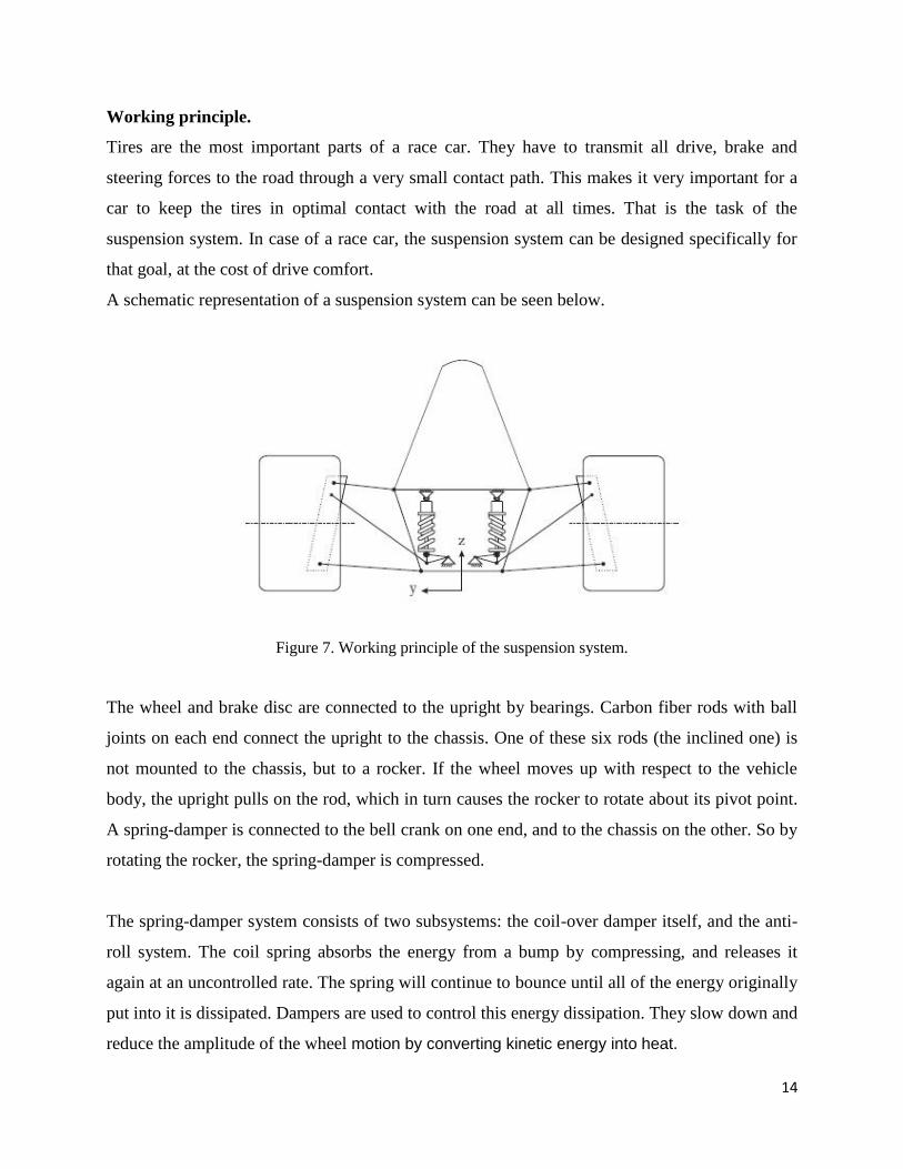
A schematic representation of a suspension system can be seen below.
Figure 7. Working principle of the suspension system.
The wheel and brake disc are connected to the upright by bearings. Carbon fiber rods with ball
joints on each end connect the upright to the chassis. One of these six rods (the inclined one) is
not mounted to the chassis, but to a rocker. If the wheel moves up with respect to the vehicle
body, the upright pulls on the rod, which in turn causes the rocker to rotate about its pivot point.
A spring-damper is connected to the bell crank on one end, and to the chassis on the other. So by
rotating the rocker, the spring-damper is compressed.
The spring-damper system consists of two subsystems: the coil-over damper itself, and the anti-
roll system. The coil spring absorbs the energy from a bump by compressing, and releases it
again at an uncontrolled rate. The spring will continue to bounce until all of the energy originally
put into it is dissipated. Dampers are used to control this energy dissipation. They slow down and
reduce the amplitude of the wheel motion by converting kinetic energy into heat.

15
The anti-roll system consists of a torsion bar with a lever on each end. If the movements on
each end of the bar are not exactly the same, it will be twisted. This results in a reaction force.
The main rocker connects the pull rod to the two subsystems. The geometry of this rocker determines the
movement of the spring-damper and the anti-roll bar as a result of the movement of the pull rod.
Two operating conditions will be explained to show how the subsystems work to control the movements
of the suspension.
Bump situation.
If the car drives over a threshold, the left and right wheels will move up an equal amount. This
results in the same angular rotation of the left and right main rocker.
The spring-dampers are therefore actuated equally. Since left and right levers of the anti-roll bar
are rotated to the same angle in the same direction, it will not create a reaction moment.
Cornering situation.
If the car drives through a corner, it's body will roll to the outside of the bend. As a result, the
outer wheel moves up with respect to the chassis, and the inner wheel will move down. This
means the main rockers are rotated in opposite directions. The load on the outside spring will
become higher, while the inside spring will be (partially) unloaded. The anti-roll bar will be
twisted, which results in an opposing moment that tries to keep the vehicle body level.
Figure 8. Concerning situation: Bump, corner.
16
Types of Suspension.
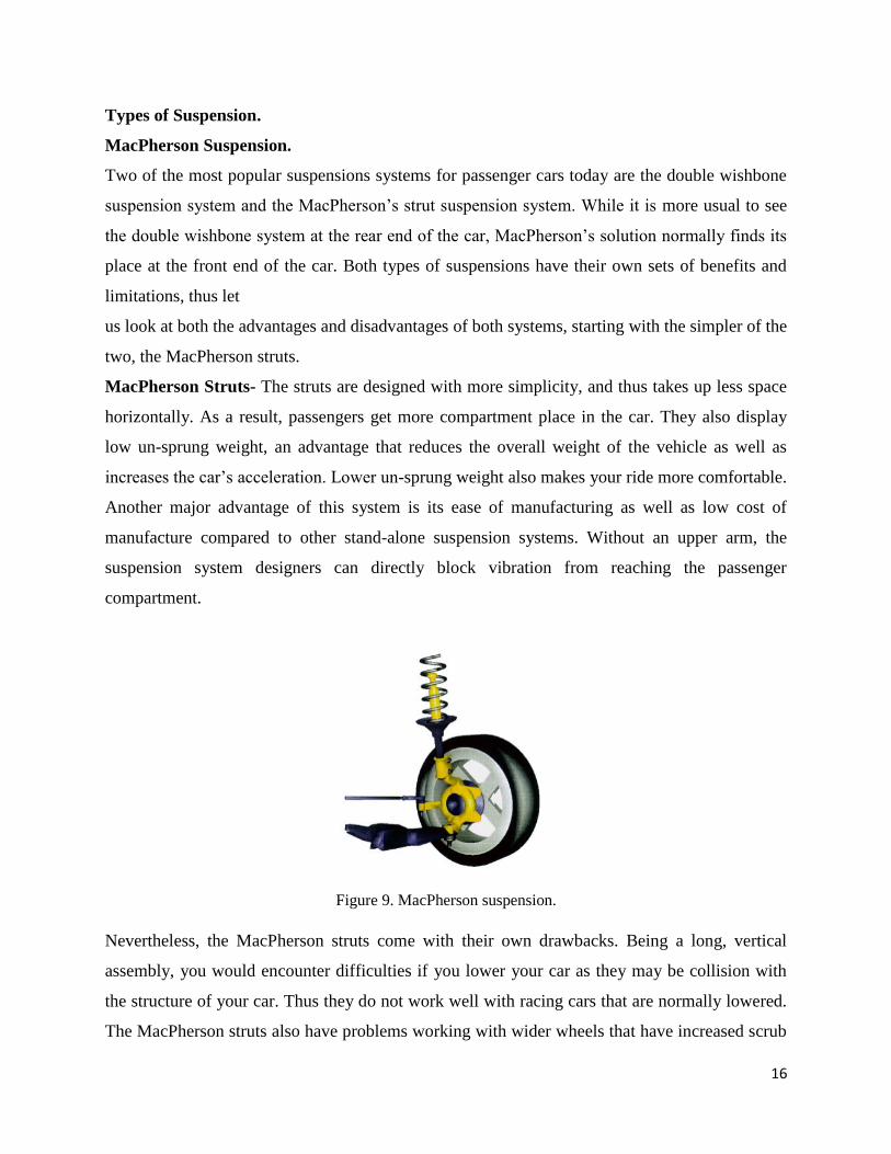
MacPherson Suspension.
Two of the most popular suspensions systems for passenger cars today are the double wishbone
suspension system and the MacPherson’s strut suspension system. While it is more usual to see
the double wishbone system at the rear end of the car, MacPherson’s solution normally finds its
place at the front end of the car. Both types of suspensions have their own sets of benefits and
limitations, thus let
us look at both the advantages and disadvantages of both systems, starting with the simpler of the
two, the MacPherson struts.
MacPherson Struts- The struts are designed with more simplicity, and thus takes up less space
horizontally. As a result, passengers get more compartment place in the car. They also display
low un-sprung weight, an advantage that reduces the overall weight of the vehicle as well as
increases the car’s acceleration. Lower un-sprung weight also makes your ride more comfortable.
Another major advantage of this system is its ease of manufacturing as well as low cost of
manufacture compared to other stand-alone suspension systems. Without an upper arm, the
suspension system designers can directly block vibration from reaching the passenger
compartment.
Figure 9. MacPherson suspension.
Nevertheless, the MacPherson struts come with their own drawbacks. Being a long, vertical
assembly, you would encounter difficulties if you lower your car as they may be collision with
the structure of your car. Thus they do not work well with racing cars that are normally lowered.
The MacPherson struts also have problems working with wider wheels that have increased scrub
17
radius, where you would need extra effort to navigate your car in this situation. There is also the
problem with the small camber change with vertical movement of the suspension, which could
mean the tires have less contact with the road during cornering. This could reduce handling
abilities of your vehicle.
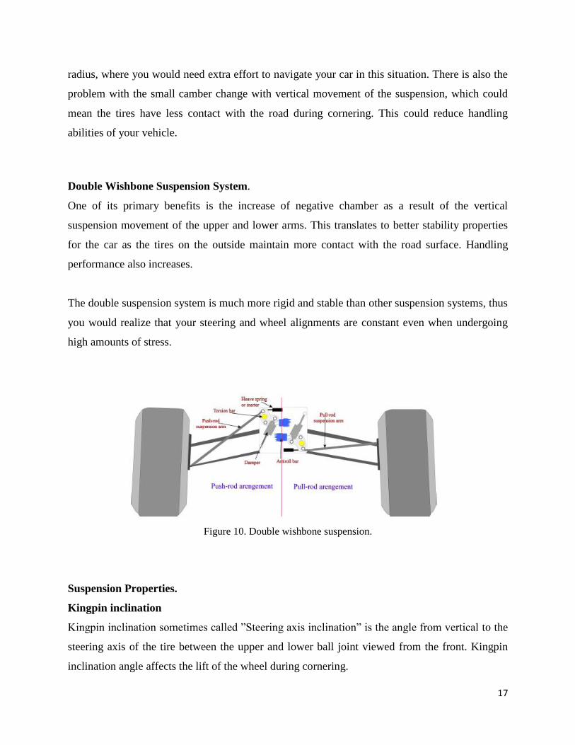
Double Wishbone Suspension System.
One of its primary benefits is the increase of negative chamber as a result of the vertical
suspension movement of the upper and lower arms. This translates to better stability properties
for the car as the tires on the outside maintain more contact with the road surface. Handling
performance also increases.
The double suspension system is much more rigid and stable than other suspension systems, thus
you would realize that your steering and wheel alignments are constant even when undergoing
high amounts of stress.
Figure 10. Double wishbone suspension.
Suspension Properties.
Kingpin inclination
Kingpin inclination sometimes called ”Steering axis inclination” is the angle from vertical to the
steering axis of the tire between the upper and lower ball joint viewed from the front. Kingpin
inclination angle affects the lift of the wheel during cornering.
18
As it lifts the car as it corners and makes the wheels want to steer straight as the weight of the
car returns the steering to centre. The kingpin inclination angle also affects the camber angle of
the wheels as they turn and the wheel will gain positive camber. This can be beneficial to the
handling of the car when making tight turns.
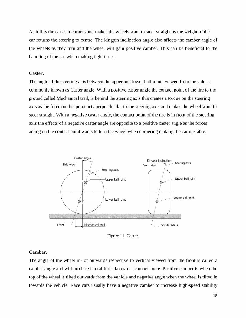
Caster.
The angle of the steering axis between the upper and lower ball joints viewed from the side is
commonly known as Caster angle. With a positive caster angle the contact point of the tire to the
ground called Mechanical trail, is behind the steering axis this creates a torque on the steering
axis as the force on this point acts perpendicular to the steering axis and makes the wheel want to
steer straight. With a negative caster angle, the contact point of the tire is in front of the steering
axis the effects of a negative caster angle are opposite to a positive caster angle as the forces
acting on the contact point wants to turn the wheel when cornering making the car unstable.
Figure 11. Caster.
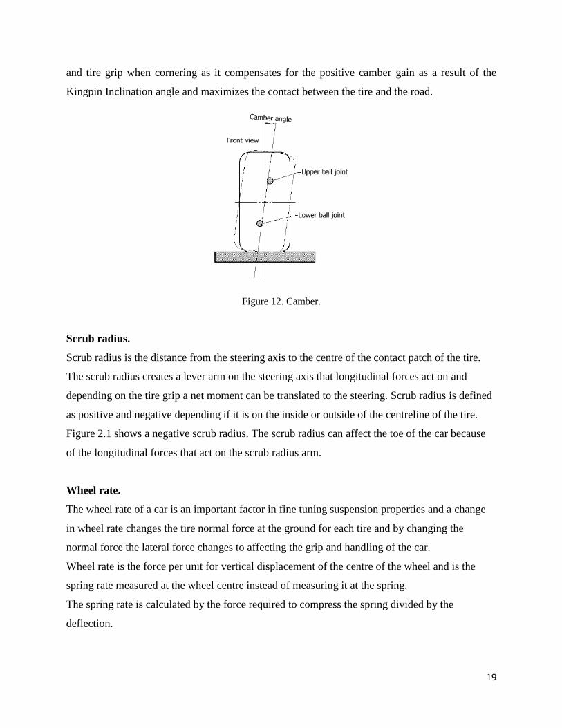
Camber.
The angle of the wheel in- or outwards respective to vertical viewed from the front is called a
camber angle and will produce lateral force known as camber force. Positive camber is when the
top of the wheel is tilted outwards from the vehicle and negative angle when the wheel is tilted in
towards the vehicle. Race cars usually have a negative camber to increase high-speed stability
19
and tire grip when cornering as it compensates for the positive camber gain as a result of the
Kingpin Inclination angle and maximizes the contact between the tire and the road.
Figure 12. Camber.
Scrub radius.
Scrub radius is the distance from the steering axis to the centre of the contact patch of the tire.
The scrub radius creates a lever arm on the steering axis that longitudinal forces act on and
depending on the tire grip a net moment can be translated to the steering. Scrub radius is defined
as positive and negative depending if it is on the inside or outside of the centreline of the tire.
Figure 2.1 shows a negative scrub radius. The scrub radius can affect the toe of the car because
of the longitudinal forces that act on the scrub radius arm.
Wheel rate.
The wheel rate of a car is an important factor in fine tuning suspension properties and a change
in wheel rate changes the tire normal force at the ground for each tire and by changing the
normal force the lateral force changes to affecting the grip and handling of the car.
Wheel rate is the force per unit for vertical displacement of the centre of the wheel and is the
spring rate measured at the wheel centre instead of measuring it at the spring.
The spring rate is calculated by the force required to compress the spring divided by the
deflection.
20
3 CHAPTER 3. Design process.
Requirements.
To design the suspension system for the HU-2, a set of requirements has to be formulated.
These can be split up in general requirements that apply to all parts designed for HU-2, and
demands that apply specifically to the suspension system.
The general requirements are:
1. High reliability.
2. Low weight.
3. Low centre of gravity.
4. Low yaw inertia.
5. Low production costs. This includes both the prototype and series production of
1000 cars/year.
6. Must comply with FSAE rules [1].
The spring-damper system's specific requirements are:
7. The motion ratio (see equation 1) has to suit the chosen dampers.
8. The anti-roll system has to be adjustable. This can be used to control the over- and
understeer behaviour of the car. The system has to be adjustable from 0:5k � 2k.
9. Accessibility has to be such that settings can quickly be adjusted.
10. Friction (hysteresis) has to be kept low.
11. The system should be free of play.
12. Wheel displacement has to be measured with integrated sensors.
13. The required stiffness of the anti-roll bars and bump springs will be determined by
the designers of the new multilink suspension. An advanced vehicle model will be
used for this.
14. Minimum wheel travel is prescribed by rule B6.1.1 [1]:
B6.1.1 The car must be equipped with a fully operational suspension system with shock
absorbers, front and rear, with usable wheel travel of at least 50.8 mm (2 inches), 25.4 mm (1
inch) jounce and 25.4 mm (1 inch) rebound, with driver seated. The judges reserve the right to
disqualify cars which do not represent a serious attempt at an operational suspension system or
which demonstrate handling inappropriate for an autocross circuit.
21
15. Visibility is prescribed by rule B6.1.2 [1]:
B6.1.2 All suspension mounting points must be visible at Technical Inspection, either by direct
view or by removing any covers.
16. Ground clearance is prescribed by rule B6.2 [1]:
B6.2 The ground clearance must be sufficient to prevent any portion of the car (other than tires)
from touching the ground during track events, and with the driver aboard there must be a
minimum of 25.4 mm (1 inch).
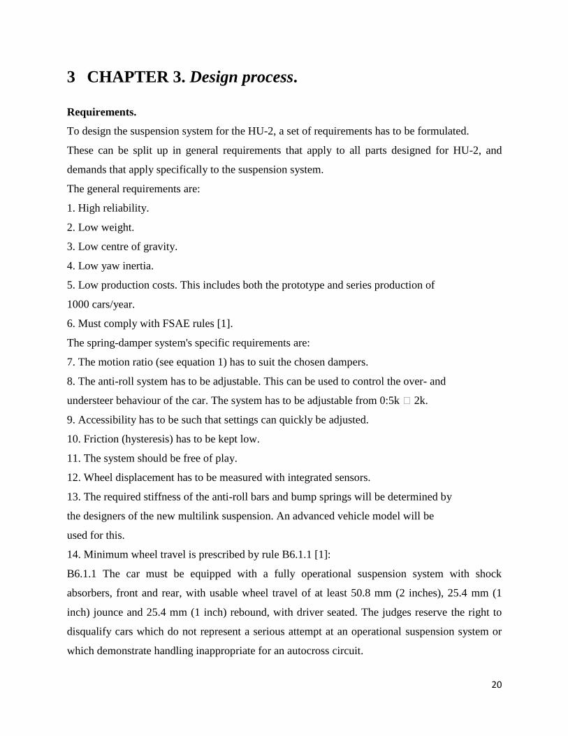
Manufacturing.
The main structure/frame of the HU-2 is built using steel tubes.
Figure 13. Structure and frame of the HU-2 race car.

22
Figure 14. Building and manufacturing race car structure at Beta factory workshop, Delft.
23
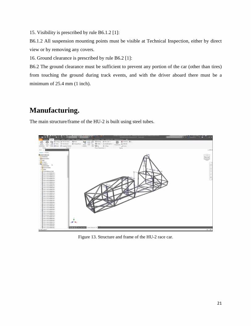
Details of the suspension system.
Figure 15. Upright, suspension.
Tasks.
1- Look if the old wheel hub fits in the new upright (in Inventor).
24
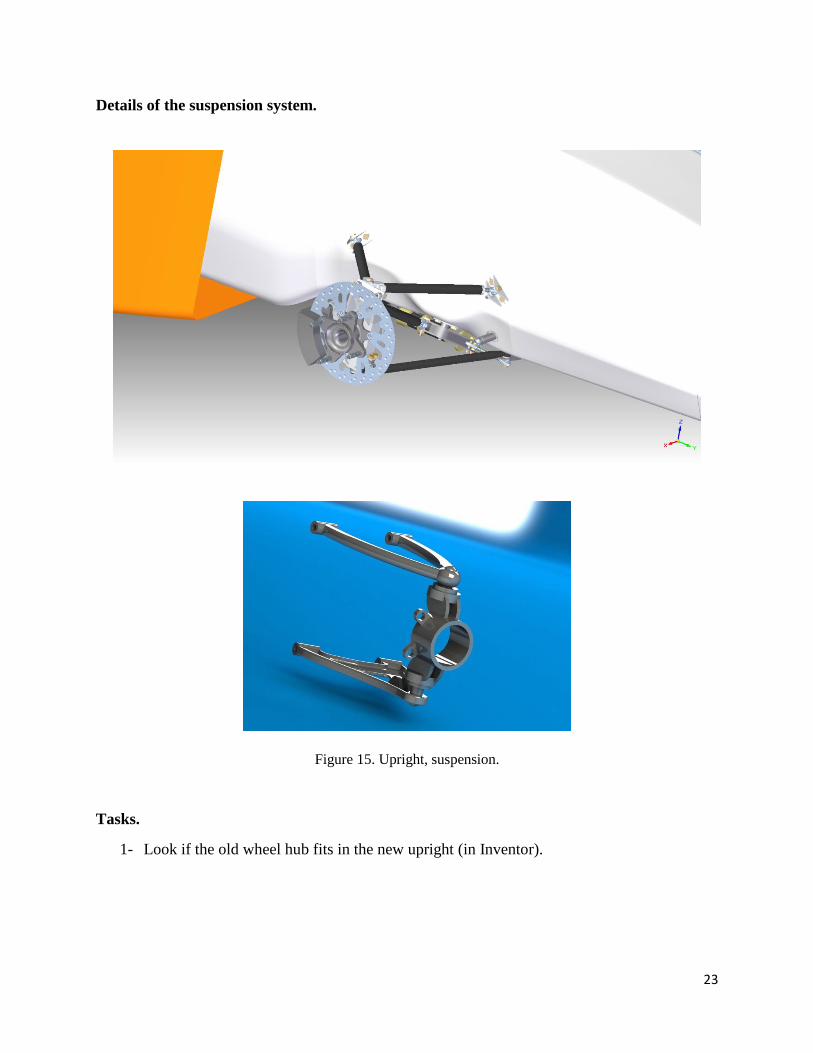
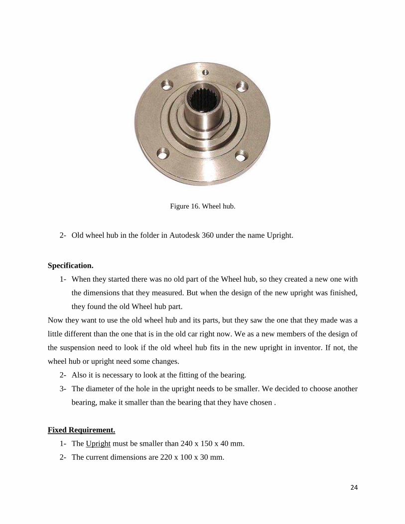
Figure 16. Wheel hub.
2- Old wheel hub in the folder in Autodesk 360 under the name Upright.
Specification.
1- When they started there was no old part of the Wheel hub, so they created a new one with
the dimensions that they measured. But when the design of the new upright was finished,
they found the old Wheel hub part.
Now they want to use the old wheel hub and its parts, but they saw the one that they made was a
little different than the one that is in the old car right now. We as a new members of the design of
the suspension need to look if the old wheel hub fits in the new upright in inventor. If not, the
wheel hub or upright need some changes.
2- Also it is necessary to look at the fitting of the bearing.
3- The diameter of the hole in the upright needs to be smaller. We decided to choose another
bearing, make it smaller than the bearing that they have chosen .
Fixed Requirement.
1- The Upright must be smaller than 240 x 150 x 40 mm.
2- The current dimensions are 220 x 100 x 30 mm.
25
3- The Upright needs to be 20 % lighter than the current. The current Uproght weighs about
1 kg.
4- The Upright needs to be inexpensive. Cost reduction of 10 %.
5- The design must be producible.
6- FSAE requirements that are associated with the Upright.
For all that, we have decided to make some modification.
Current Dimensions of Upright. 232 x 148 x 30 mm
Diameter of the hole 85 mm.
Wheelhub dimensions 120 x 45 mm
Ball Bearing fits Wheelhub. SKF 3208A (External diameter 85 mm; Internal Diameter 45 mm).
Subsystems of the Suspension
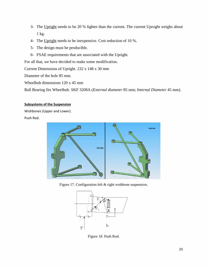
Wishbones (Upper and Lower).
Push Rod.
Figure 17. Configuration left & right wishbone suspension.
Figure 18. Push Rod.
26
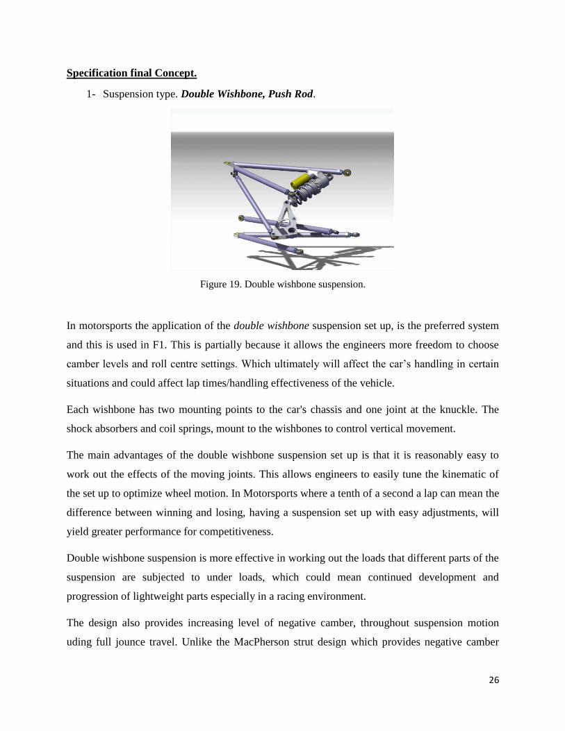
Specification final Concept.
1- Suspension type. Double Wishbone, Push Rod.
Figure 19. Double wishbone suspension.
In motorsports the application of the double wishbone suspension set up, is the preferred system
and this is used in F1. This is partially because it allows the engineers more freedom to choose
camber levels and roll centre settings. Which ultimately will affect the car’s handling in certain
situations and could affect lap times/handling effectiveness of the vehicle.
Each wishbone has two mounting points to the car's chassis and one joint at the knuckle. The
shock absorbers and coil springs, mount to the wishbones to control vertical movement.
The main advantages of the double wishbone suspension set up is that it is reasonably easy to
work out the effects of the moving joints. This allows engineers to easily tune the kinematic of
the set up to optimize wheel motion. In Motorsports where a tenth of a second a lap can mean the
difference between winning and losing, having a suspension set up with easy adjustments, will
yield greater performance for competitiveness.
Double wishbone suspension is more effective in working out the loads that different parts of the
suspension are subjected to under loads, which could mean continued development and
progression of lightweight parts especially in a racing environment.
The design also provides increasing level of negative camber, throughout suspension motion
uding full jounce travel. Unlike the MacPherson strut design which provides negative camber
27
gains, only at the beginning of jounce travel and then reverses into positive camber gains at high
jounce level amounts. The Double Wishbone design has disadvantage, in that it is slightly more
complex than other systems like a MacPherson strut and will be more expensive to manufacture.
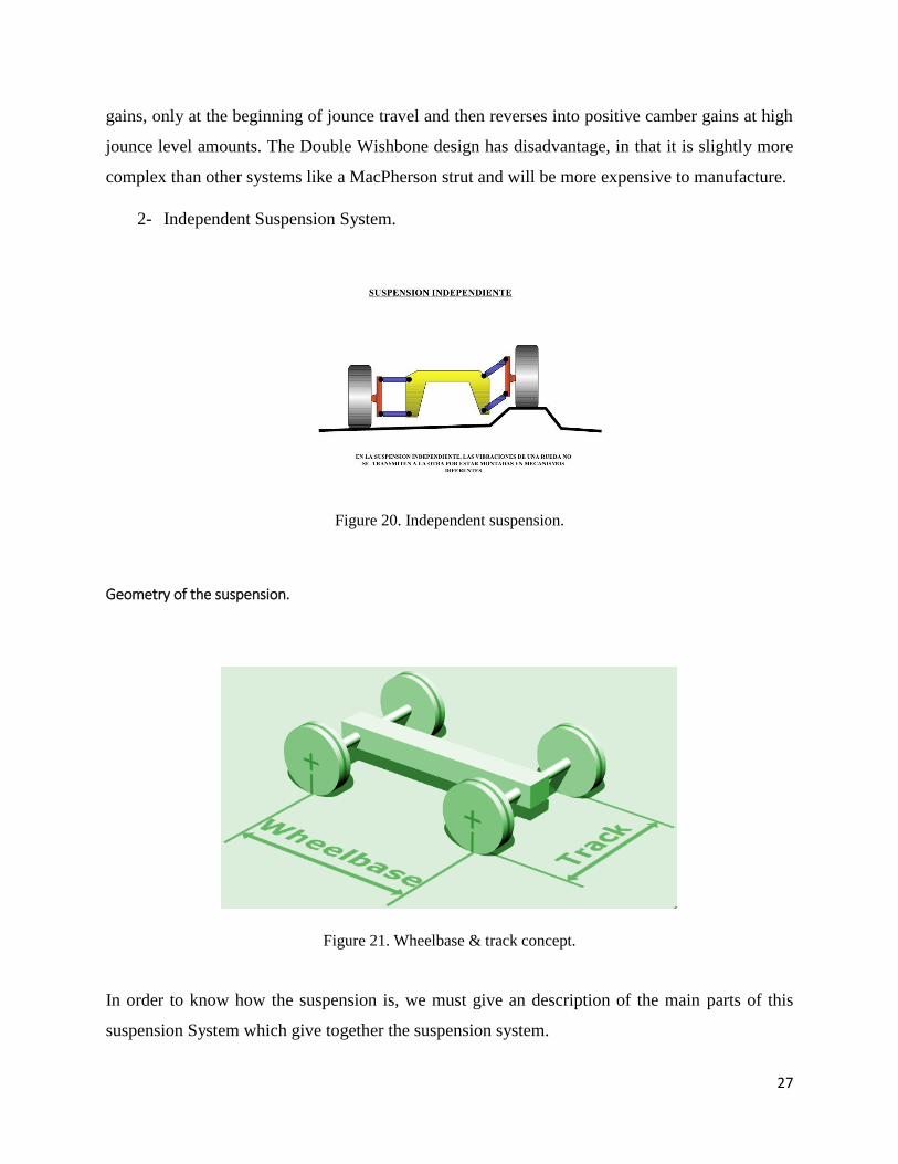
2- Independent Suspension System.
Figure 20. Independent suspension.
Geometry of the suspension.
Figure 21. Wheelbase & track concept.
In order to know how the suspension is, we must give an description of the main parts of this
suspension System which give together the suspension system.
28
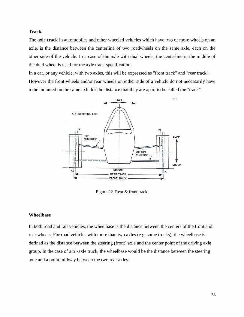
Track.
The axle track in automobiles and other wheeled vehicles which have two or more wheels on an
axle, is the distance between the centerline of two roadwheels on the same axle, each on the
other side of the vehicle. In a case of the axle with dual wheels, the centerline in the middle of
the dual wheel is used for the axle track specification.
In a car, or any vehicle, with two axles, this will be expressed as "front track" and "rear track".
However the front wheels and/or rear wheels on either side of a vehicle do not necessarily have
to be mounted on the same axle for the distance that they are apart to be called the "track".
Figure 22. Rear & front track.
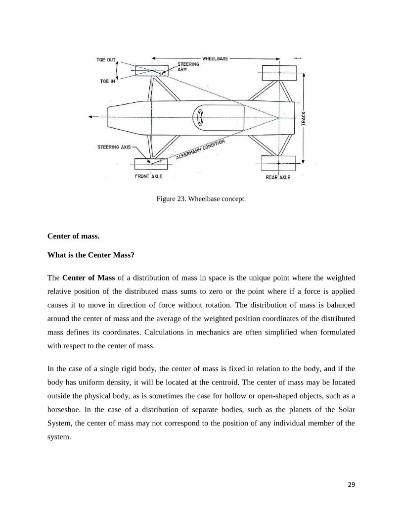
Wheelbase
In both road and rail vehicles, the wheelbase is the distance between the centers of the front and
rear wheels. For road vehicles with more than two axles (e.g. some trucks), the wheelbase is
defined as the distance between the steering (front) axle and the center point of the driving axle
group. In the case of a tri-axle truck, the wheelbase would be the distance between the steering
axle and a point midway between the two rear axles.
29
Figure 23. Wheelbase concept.
Center of mass.
What is the Center Mass?
The Center of Mass of a distribution of mass in space is the unique point where the weighted
relative position of the distributed mass sums to zero or the point where if a force is applied
causes it to move in direction of force without rotation. The distribution of mass is balanced
around the center of mass and the average of the weighted position coordinates of the distributed
mass defines its coordinates. Calculations in mechanics are often simplified when formulated
with respect to the center of mass.
In the case of a single rigid body, the center of mass is fixed in relation to the body, and if the
body has uniform density, it will be located at the centroid. The center of mass may be located
outside the physical body, as is sometimes the case for hollow or open-shaped objects, such as a
horseshoe. In the case of a distribution of separate bodies, such as the planets of the Solar
System, the center of mass may not correspond to the position of any individual member of the
system.
30
The center of mass is a useful reference point for calculations in mechanics that involve masses
distributed in space, such as the linear and angular momentum of planetary bodies and rigid body
dynamics. In orbital mechanics, the equations of motion of planets are formulated as point
masses located at the centers of mass. The center of mass frame is an inertial frame in which the
center of mass of a system is at rest with respect to the origin of the coordinate system.
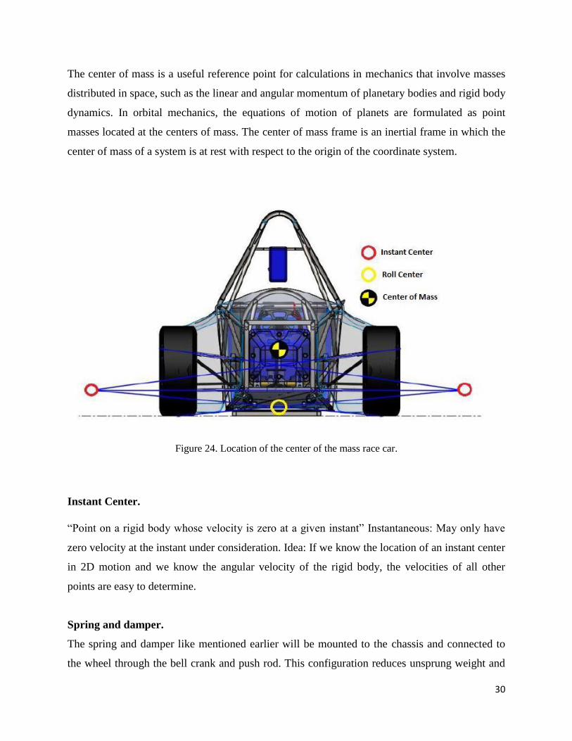
Figure 24. Location of the center of the mass race car.
Instant Center.
“Point on a rigid body whose velocity is zero at a given instant” Instantaneous: May only have
zero velocity at the instant under consideration. Idea: If we know the location of an instant center
in 2D motion and we know the angular velocity of the rigid body, the velocities of all other
points are easy to determine.
Spring and damper.
The spring and damper like mentioned earlier will be mounted to the chassis and connected to
the wheel through the bell crank and push rod. This configuration reduces unsprung weight and

31
improves the response of the suspension system. The suspension system uses coil over springs
where the springs are mounted to the outside of the damper with an adjustable preload on the
spring to adjust the ride height of the car.
The dampers are twin tube with adjustable high and low-speed rebound and compression these
settings are important in fine-tuning the suspension. In twin-tube dampers, there are two
chambers full of oil in the damper and when the damper is moved the piston moves the oil
through the needle valves. The needle valves control the flow of liquid through the orifice in the
valve seat restricting the flow of the oil and thus providing controllable flow. The Öhlins TTX
MkII has a gas chamber that pressurizes the oil inside the damper with a piston that separates the
gas from the oil. By having the oil inside the damper pressurized, improves the performance of
the damper and prevents air bubbles forming in the oil and reduces hysteresis
Anti-roll bar
The anti-roll bars are used to increase the roll stiffness of the car during lateral acceleration and
are an important factor in fine-tuning the roll stiffness of the car. The anti-roll bar works by
taking the linear motion of the suspension and provide torsional stiffness through a rod or tube.
This transfers some of the forces of the vertical forces between the tires during cornering and
increases grip. The anti-roll bars are mounted low in the chassis to lower the CoG and have links
to the bell cranks.
Figure 25. Shock absorber.
32
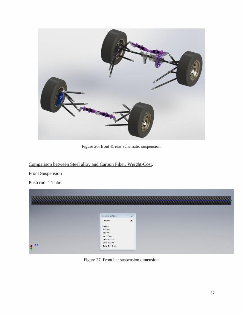
Figure 26. front & rear schematic suspension.
Comparison between Steel alloy and Carbon Fiber. Weight-Cost.
Front Suspension
Push rod. 1 Tube.
Figure 27. Front bar suspension dimension.
33
Material Weight (kg) Length (mm) Cost (€)
Steel alloy 1,014 447 34,38 ↑
Carbon Fiber 0,203 447 7,56 ↓
Table 1. Difference costs between Steel alloy and Carbon Fiber to the Front Push Rod.
Costs:
Carbon Fiber: 100 € per 1300 mm.
Steel Alloy: 22 € per 1300 mm.
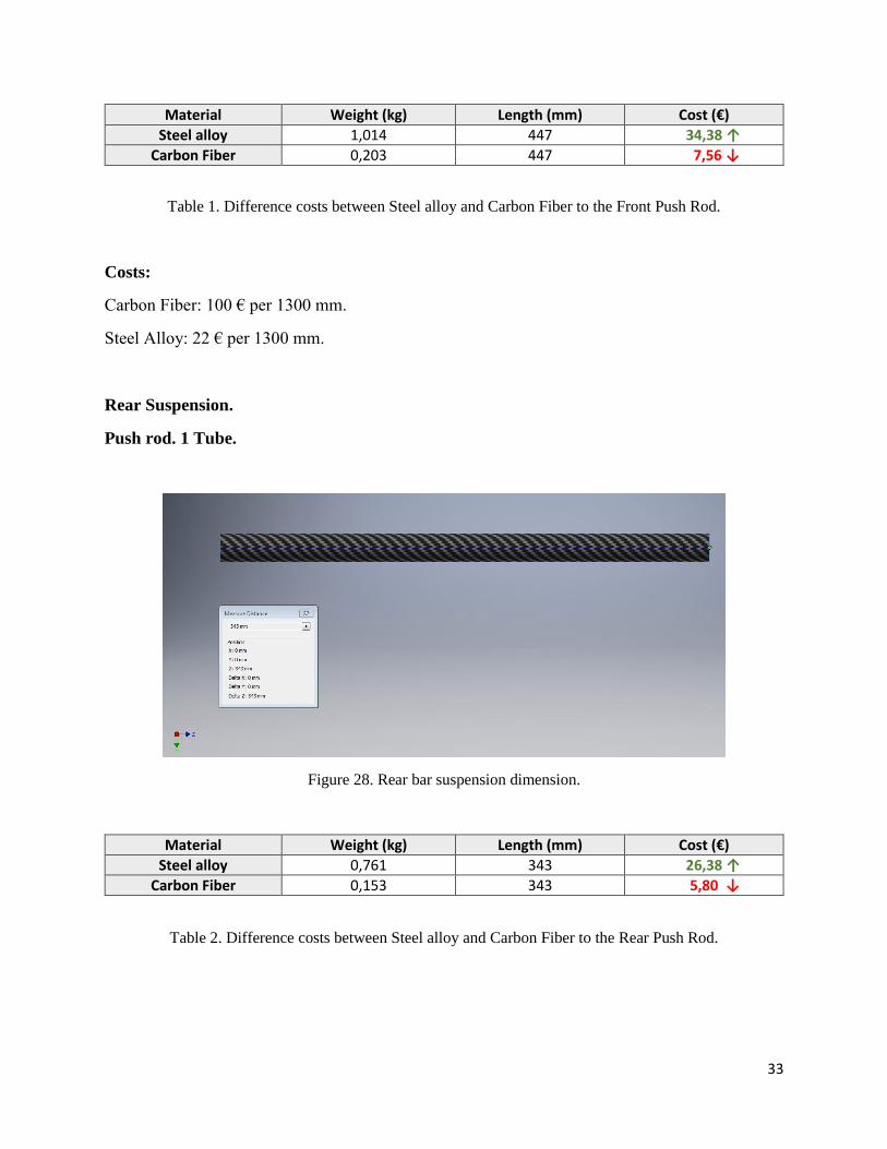
Rear Suspension.
Push rod. 1 Tube.
Figure 28. Rear bar suspension dimension.
Material Weight (kg) Length (mm) Cost (€)
Steel alloy 0,761 343 26,38 ↑
Carbon Fiber 0,153 343 5,80 ↓
Table 2. Difference costs between Steel alloy and Carbon Fiber to the Rear Push Rod.

34
Figure 29. Details of the lateral inserts of the bar suspension.

35
4 CHAPTER 4. Calculation of the suspension system.
Braking force.
Acceleration.
Fa -3616,9 N m 375 kg
m 3678,75 N
L1 0,309 m g 9,81 m/s²
L2 0,942 m v 27,7778 m/s
L3 0,628 m s 80 m
t 2,879998 sec
moment b: Fa(max) 1345,849 N a -9,64508 m/s²
3465,383 N Fg -0,98319 gN
-1117,62 N
1,57 m ∑ Fy = 0
Na 1495,388 N Nb 2183,362 N
N'a 747,694 N N'b 1091,681 N
Fa 2604,1688 N m 375 kg
v 27,7778 m/s
L1 0,309 m t 4 s
L2 0,942 m a 6,94445 m/s²
L3 0,628 m
moment b: Fa(max) 863,0638 N
2310,255 N
804,68814 N
1,57 m ∑ Fy = 0
Na 958,95978 N Nb 2719,79 N
N'a 479,47989 N N'b 1359,895 N

36
Rear.
Total.
L1 0,309 m
L2 1,225 m
Fz 2207,25 N
Fc 1986,525 N
Fn_t 3678,75 N
Moment F1 = 0
L2*Fn2 - L2/2 *Fz -L1*Fc = 0
Fn2 1604,716 N
Fw2 1444,244 N
∑ Fy = 0
Fn1 + Fn2 - Fz = 0
Fn1 602,5342 N
Fw1 542,2808 N
L1 1,57 m a 0,567232 rad 32,5
L2 1,225 m b 0,39043 rad 22,37
Lr(4/10*L1) 0,628 m g 0,178024 rad 10,2
Lf(6/10*L1) 0,942 m Fx11 612,3664 N
g 9,81 m/s² Fx12 558,4938 N
m 375 kg Fx21 662,2 N
m 3678,75 N Fx22 662,2 N
m 0,9
Fc_total 3310,875 N
Moment w3 =0:
L2*Fw4y - Lf*cos( g )Fc - 0,5*L2*sin( g )Fc +L1*Fw2 + L1*Fw1 -( Fx11y*L2 - Fx21*L2)= 0
1,225 m
-3069,55 N
-359,112 N
2267,463 N
851,3808 N
-1622,39 N
Fw4y 1577,315 N
Fw4 4144,435 N
Fn4 4604,928 N
∑ Fy = 0 ∑ Fx = 0
Fc*sin( g ) - Fw4y-Fw3y*sin( a ) = 0 Fw4*cos( b ) + Fw3x*cos( a ) - Fc*cos( g ) + Fw2 + Fw1 = 0
586,3054 N 3832,5471 N
1577,315 N -3258,549 N
0,5373 N 1444,2442 N
Fw3y -991,009 N 542,28078 N
Fw3x 2560,5235 N
Fw3 2745,611 N
Fn3 3050,679 N
37
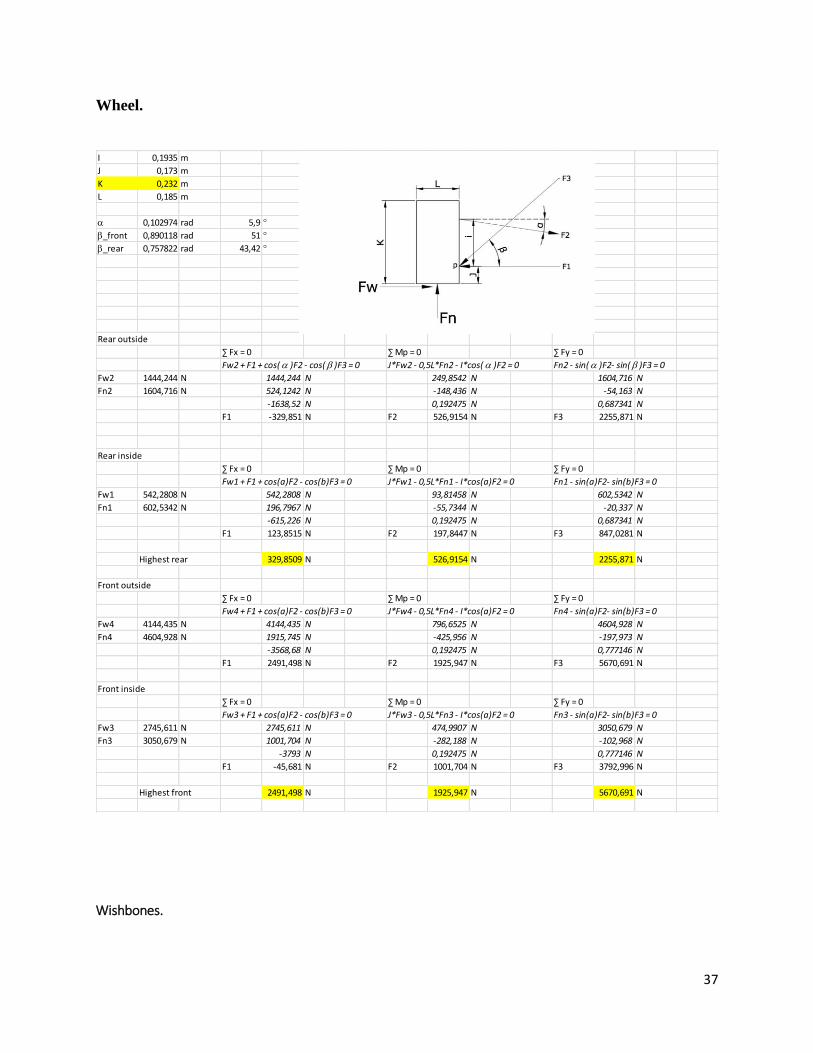
Wheel.
Wishbones.
I 0,1935 m
J 0,173 m
K 0,232 m
L 0,185 m
a 0,102974 rad 5,9
b_front 0,890118 rad 51
b_rear 0,757822 rad 43,42
Rear outside
∑ Fx = 0 ∑ Mp = 0 ∑ Fy = 0
Fw2 + F1 + cos( a )F2 - cos( b )F3 = 0 J*Fw2 - 0,5L*Fn2 - I*cos( a )F2 = 0 Fn2 - sin( a )F2- sin( b )F3 = 0
Fw2 1444,244 N 1444,244 N 249,8542 N 1604,716 N
Fn2 1604,716 N 524,1242 N -148,436 N -54,163 N
-1638,52 N 0,192475 N 0,687341 N
F1 -329,851 N F2 526,9154 N F3 2255,871 N
Rear inside
∑ Fx = 0 ∑ Mp = 0 ∑ Fy = 0
Fw1 + F1 + cos(a)F2 - cos(b)F3 = 0 J*Fw1 - 0,5L*Fn1 - I*cos(a)F2 = 0 Fn1 - sin(a)F2- sin(b)F3 = 0
Fw1 542,2808 N 542,2808 N 93,81458 N 602,5342 N
Fn1 602,5342 N 196,7967 N -55,7344 N -20,337 N
-615,226 N 0,192475 N 0,687341 N
F1 123,8515 N F2 197,8447 N F3 847,0281 N
Highest rear 329,8509 N 526,9154 N 2255,871 N
Front outside
∑ Fx = 0 ∑ Mp = 0 ∑ Fy = 0
Fw4 + F1 + cos(a)F2 - cos(b)F3 = 0 J*Fw4 - 0,5L*Fn4 - I*cos(a)F2 = 0 Fn4 - sin(a)F2- sin(b)F3 = 0
Fw4 4144,435 N 4144,435 N 796,6525 N 4604,928 N
Fn4 4604,928 N 1915,745 N -425,956 N -197,973 N
-3568,68 N 0,192475 N 0,777146 N
F1 2491,498 N F2 1925,947 N F3 5670,691 N
Front inside
∑ Fx = 0 ∑ Mp = 0 ∑ Fy = 0
Fw3 + F1 + cos(a)F2 - cos(b)F3 = 0 J*Fw3 - 0,5L*Fn3 - I*cos(a)F2 = 0 Fn3 - sin(a)F2- sin(b)F3 = 0
Fw3 2745,611 N 2745,611 N 474,9907 N 3050,679 N
Fn3 3050,679 N 1001,704 N -282,188 N -102,968 N
-3793 N 0,192475 N 0,777146 N
F1 -45,681 N F2 1001,704 N F3 3792,996 N
Highest front 2491,498 N 1925,947 N 5670,691 N
38
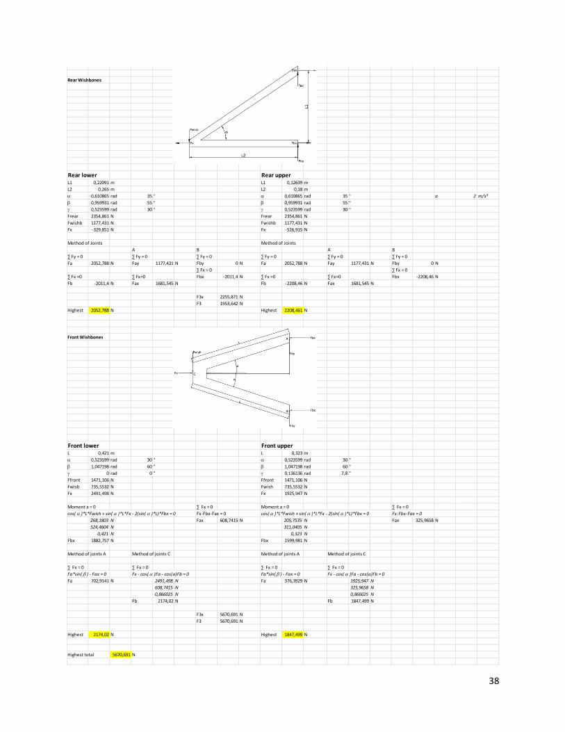
Rear Wishbones
Rear lower Rear upperL1 0,22091 m L1 0,12639 m
L2 0,265 m L2 0,18 m
a 0,610865 rad 35 a 0,610865 rad 35 a 2 m/s²
b 0,959931 rad 55 b 0,959931 rad 55
g 0,523599 rad 30 g 0,523599 rad 30
Frear 2354,861 N Frear 2354,861 N
Fwishb 1177,431 N Fwishb 1177,431 N
Fx -329,851 N Fx -526,915 N
Method of Joints Method of Joints
A B A B
∑ Fy = 0 ∑ Fy = 0 ∑ Fy = 0 ∑ Fy = 0 ∑ Fy = 0 ∑ Fy = 0
Fa 2052,788 N Fay 1177,431 N Fby 0 N Fa 2052,788 N Fay 1177,431 N Fby 0 N
∑ Fx = 0 ∑ Fx = 0
∑ Fx =0 ∑ Fx=0 Fbx -2011,4 N ∑ Fx =0 ∑ Fx=0 Fbx -2208,46 N
Fb -2011,4 N Fax 1681,545 N Fb -2208,46 N Fax 1681,545 N
F3x 2255,871 N
F3 1953,642 N
Highest 2052,788 N Highest 2208,461 N
Front Wishbones
Front lower Front upperL 0,421 m L 0,323 m
a 0,523599 rad 30 ° a 0,523599 rad 30 °
b 1,047198 rad 60 ° b 1,047198 rad 60 °
g 0 rad 0 ° g 0,136136 rad 7,8 °
Ffront 1471,106 N Ffront 1471,106 N
Fwisb 735,5532 N Fwish 735,5532 N
Fx 2491,498 N Fx 1925,947 N
Moment a = 0 ∑ Fx = 0 Moment a = 0 ∑ Fx = 0
cos( a )*L*Fwish + sin( a )*L*Fx - 2(sin( a )*L)*Fbx = 0 Fx-Fbx-Fax = 0 cos( a )*L*Fwish + sin( a )*L*Fx - 2(sin( a )*L)*Fbx = 0 Fx-Fbx-Fax = 0
268,1803 N Fax 608,7415 N 205,7535 N Fax 325,9658 N
524,4604 N 311,0405 N
0,421 N 0,323 N
Fbx 1882,757 N Fbx 1599,981 N
Method of joints A Method of joints C Method of joints A Method of joints C
∑ Fx = 0 ∑ Fx = 0 ∑ Fx = 0 ∑ Fx = 0
Fa*sin( b ) - Fax = 0 Fx - cos( a )Fa - cos(a)Fb = 0 Fa*sin( b ) - Fax = 0 Fx - cos( a )Fa - cos(a)Fb = 0
Fa 702,9141 N 2491,498 N Fa 376,3929 N 1925,947 N
608,7415 N 325,9658 N
0,866025 N 0,866025 N
Fb 2174,02 N Fb 1847,499 N
F3x 5670,691 N
F3 5670,691 N
Highest 2174,02 N Highest 1847,499 N
Highest total 5670,691 N
39
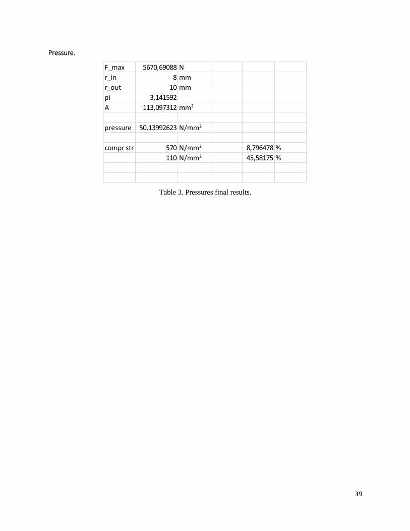
Pressure.
Table 3. Pressures final results.
F_max 5670,69088 N
r_in 8 mm
r_out 10 mm
pi 3,141592
A 113,097312 mm²
pressure 50,13992623 N/mm²
compr str 570 N/mm² 8,796478 %
110 N/mm² 45,58175 %

40
5 CHAPTER 5. Autodesk Inventor 3D MODELS.
Bell Crank bracket.
Figure 30. Bell crank bracket.
Bell Crank Front Plate.
Figure 31. Bell crank front plate.
Bell Crank Rear Plate.
Figure 32. Bell crank rear plate.
41
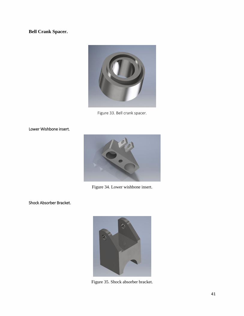
Bell Crank Spacer.
Figure 33. Bell crank spacer.
Lower Wishbone insert.
Figure 34. Lower wishbone insert.
Shock Absorber Bracket.
Figure 35. Shock absorber bracket.
42
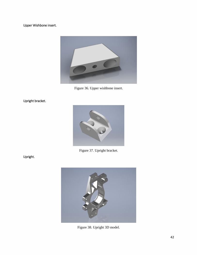
Upper Wishbone insert.
Figure 36. Upper wishbone insert.
Upright bracket.
Figure 37. Upright bracket.
Upright.
Figure 38. Upright 3D model.
43
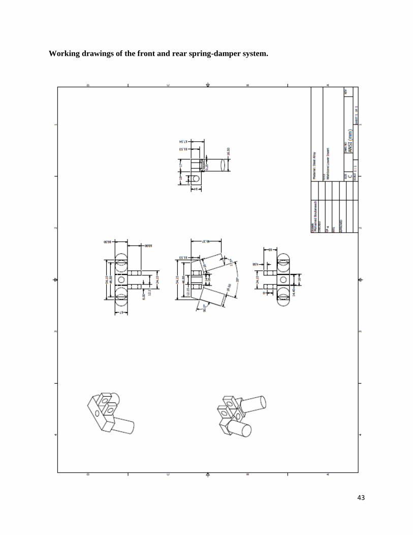
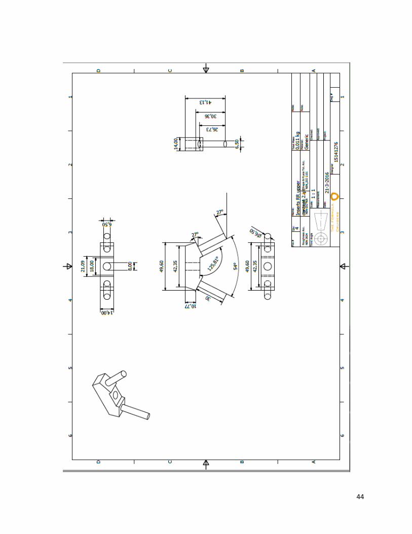
Working drawings of the front and rear spring-damper system.
44

45
6 CHAPTER 6. Conclusion.
As the main objectives of this thesis were to gain a better understanding of how suspension
systems work and combine theory and practical knowledge by designing and manufacturing the
suspension system.
In the thesis suspension properties like camber, caster and kingpin inclination angle was
explained and what effects on the overall handling of the car they have.
The manufacturing process is also explained and how the design could be as simple as possible
without sacrificing performance.
3D model of the final assembly is as follow:
Figure 39. Final configuration adopted for the HU-2 race car. The Hague University of applied sciences.
46
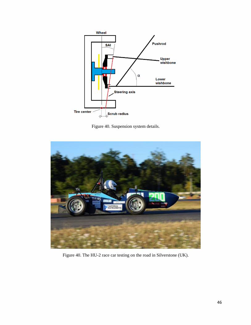
Figure 40. Suspension system details.
Figure 40. The HU-2 race car testing on the road in Silverstone (UK).

47
7 CHAPTER 7. References.
Formula Student. General Technical Requirement, 2016.
Design of machine elements, Volume II. T. Krishna Rao.
Tratado sobre automóviles. Tomo IV. La dinámica del automóvil.
Diseño de maquinaria. Edición V. Robert L. Norton.
Becker, G. Et al. (1931) “Schwingungen in Automobillernkung”. Krayn Berlag. Berlin.
Broulhiet, G. (1925). “The suspension and the automobile steering mechanism”. Societe des
Ingenieurs Civils de France Bulletin, Vol. 78.
CFAM. (2002). “Todo sobre el neumático”. Centro de Formación y Asesoramiento Michelin.
Dell’ Amico, F. (1971). “Steady-State Stability of the Atomobile- An Approach Based on a
Method of Tethred Vehicle Testing Using a Yaw Constraint”. Technical report prepared for
General Motors Engineering Staff” by Cornell Aeronautical Laboratory, Inc., CAL N°. YC-
3004-K-1.
Dols, J., Valero, F. (1996). “An Approach to dynamic simulation modelling using ADAMS for
the transport of wheelchair users.”
Gough, V.H. (1958). “Tire-To-Ground Contact Stresses”. WEAR, Vol. 2, N°. 2, November.
London.
Wright, P.G. (1984). “Speed Graphic”. Road and truck. June.
Segel, L. (1990). “Some reflections an early efforts to investigate the directional stability and
control of the motor car”.
Rouelle, C. (2002). “Optimum G. Knowledge Shared is Knowledged Squared”. Englewood CO
(USA).
Rice, R.S., Alianello, D.A. (1970). “A Driver Characterization function- The g-g Diagram”.
Cornell Aeronautical Lab. Report VJ-2882-K. Buffalo, USA.
McHenry, R. (1971). “Research in Automobile Dynamics- A Computer Simulation of General
Three-Dimensional Motions”.
ISO 8855 (1991). Road Vehicle Dynamics and Road – Holding ability. International
Organization for Standardization.