
Design of a clock synchronisation sub-system for parallel embedded systems
26
Transcript of Design of a clock synchronisation sub-system for parallel embedded systems

The Design of a Clock Synchronization Sub-system for ParallelEmbedded SystemsM. Fleury, A. C. Downton, A. F. Clark and H. P. SavaElectronic Systems Engineering Department, University of Essex, Wivenhoe Park, Colchester, CO4 4SQ, U.Ktel: +44 - 1206 - 872795fax: +44 - 1206 - 872900e-mail [email protected]
1

AbstractSoftware tools are being developed to support a design methodology speci�c to parallelreal-time continuous-data ow embedded systems. This paper describes the design of aglobal clock sub-system which is an essential component of an event trace tool. A newamalgam of algorithms is proposed which attends to the trade-o� between clock accuracyand the need to restrict disturbance of the application whilst recording traces. The detailsof an implementation on a hybrid parallel processor as well as the results of tracingapplications in the given problem domain are included.1 IntroductionReal-time, continuous-data ow embedded systems are an important class of engineering sys-tem for which parallel solutions have much to o�er. Examples of such systems can be foundin vision [1], radar [2], speech processing [3] and signal compression [4]. The algorithmiccomplexity and irregularity of such systems means that parallelizing compilers are unlikely toprovide much support in the near future [5, pp. 149{155]. Instead, a common design method-ology based upon Pipelines of Processor Farms (PPFs) [6] has been proposed which o�ers asingle conceptual design model which is capable of incorporating data parallelism, algorithmicparallelism or temporal parallelism within individual farms. The methodology addresses therequirement to parallelize systems composed of a number of independent algorithms, canhandle time, ordering, data dependency and feedback constraints, and produces increment-ally scalable solutions. Achievable throughput, latency and upper bound speed-up can bedetermined by analysis of the original application code.The PPF design methodology addresses an intermediate level of generality appropriate fora particular domain of applications. It is not limited to a particular machine architecture or aparticular processor topology for each farm. A message-passing paradigm is assumed but it ispossible and can be desirable to emulate message-passing on a shared-memory machine. Themethodology does, however, rely on central farmer processes distributing work and sets ofworker processes which perform that work by some means. A high-level application building2

block, a farm template, has been designed to speed up prototyping [7]. The template incor-porates instrumentation to enable event-tracing. Event traces can be used to give con�dencein the correct working of the application and to facilitate performance analysis.Since the role of the worker process is passive in the PPF methodology it is not appropriatefor the worker to initiate tracing when it has reached steady-state. To provide event traces,a centralized clock synchronization system is therefore required.The synchronization algorithm introduced in this paper is intended speci�cally to support thePPF methodology. The main features of the algorithm are:� an initialization phase in which the drift of the system from real time is assessed cent-rally;� averaging to achieve a system reference time;� subsequent refresh signals at a predetermined interval so as to prevent drift from thesystem time;� local correction of drift between refresh signals.For the clock mechanism, the essential component of a trace, we were able to providea central mechanism capable of tightening the precision of the clocks by reason of globalknowledge. If a communication harness with integrated trace instrumentation is designed forgeneral use (such as PICL [8]), a client-server clocking system may be preferred, which makesthe time-server a passive component. A client-server system is a disadvantage for tracing asit does not allow the pattern of synchronization tra�c to be controlled for the purpose ofreducing perturbation of the application, though it is more exible.2 Design CriteriaIf global time is not kept consistently when timestamping a record of events in a multi-computer application, then the ordering of signi�cant events on di�erent nodes (i.e. usually3
processors) can easily become awry. In particular, if the ordering of communication events islost then the phenomenon of `tachyons' occurs in which a message apparently arrives before itis sent. Solutions exist in which logical clocks [9, 10] are kept, but these involve time-stampingeach message. Such systems are applicable to distributed systems or where debugging is a goal[11]. Fault-tolerant solutions [12, 13, 14] typically involve O(n2) messages for n processes evenif all message journeys are con�ned to a single hop. In [15] an O(n) message solution relieson the presence of an embedded ring topology, which excludes tree-topologies, though theseare a natural topology for the data-farming applications of concern for us. Other work [16],though important theoretically, relies on complete graphs. Finally, statistical post-processingof the trace record [17] represents an alternative approach.A method involving interpolation between start and end timing pulses [18] was initiallyexplored but, though suitable for gauging intra-node process activity, was not found to besu�ciently accurate. A number of convergence algorithms [19, 20] exist but these may notprovide accurate timing at the inception of an algorithm. However, unlike distributed ornetworked methods [21], it is possible to have an initial tra�c-free phase; and one can assumethat faults are rare, allowing a centralized algorithm.A criterion for a portable design is that one should aim to avoid a solution involvinglow-level manipulation of the hardware, as for instance in the synchronized wave solution fortransputers of [22].The requirements of the centralized, portable design can thus be summarized as:� A minimum of user intervention is needed in regard to the clocking mechanism.� The design should not be dependent on any feature of the hardware such as would,for example, necessitate the use of assembly language. Solutions involving hardwareinterrupts [23] are by no means trivial to implement and equally run into the problemof application perturbation.� The number of synchronization messages should be minimized.4

� The mechanism should not rely on a particular architecture.� It should not be assumed that the system is already in steady-state or can convergeslowly to synchronization.� The times should conform to a suitable real time reference.In practice, one requires two algorithms: an algorithm to bring the clocks on all nodeswithin some minimum error range and an algorithm subsequently to maintain time againstclock drift.3 The Processing Model3.1 Processor RequirementsThe method described below is suitable for processor nodes with at least two levels of priorityand supporting internal concurrency, as is common for interrupt-driven applications. Onlylocal physical clocks are assumed to be available (most multicomputers can provide high-priority monotonic clocks with resolution of at least 1�s). An intermediary process whichacts as a monitor able to intercept communication is assumed in the model; the provision ofthe monitoring processs would be an implementation-dependent feature.One use of event traces is to provide input to a visualizer, which acts as a data-reductionagent. Current visualizers when faced with applications of varying time duration or commu-nication intensity may be limited by the display rate of the graphics terminal but this doesnot mean that one should not aim for as high a resolution as possible. Event traces mayalso be post-processed as input to an execution-driven simulation or an analytic model. In[24] there is an appropriately accurate method of supplying a global time reference, whichwas aimed at hypercube multicomputers. However, on its own this method only completelyresolves communication events. Additionally, it is important for a trace mechanism with wideusage (though within the real-time PPF environment) to provide timestamps that are notbiased by possible drift of the master clock. In particular, where interrupts occur real time5

should be maintained. If real time is not required then it will be su�cient to synchronize toan uncorrected master clock. (The whole system will drift at the same linear rate.)3.2 Local Clock RequirementsExperimental evidence [25] shows that crystal clocks drift linearly if the temperature regimeis constant and that anyway drift is small (< 10�5) so that second order terms are neglectedin the following. (For runs longer than a few minutes temperature oscillations may occur fortransputer clocks [26], in which case second order corrective terms o�er one solution.) It istherefore assumed that for correct clocks the accuracy of clocks should be such that(1� f)(t� t0)� � � H(t)�H(t0) � (1 + f)(t� t0) + �; (1)where f is the maximum clock frequency drift, t is a notional reference time (real time) such asUniversal Time Coordinated (UTC) [21], � is the discrete clock precision, H(t) is the readingof a clock at time t and (t� t0) > �.4 The Synchronization Model4.1 Normal BehaviourIf the system is assumed to be in steady-state and the refresh interval has been calculated,normal behaviour proceeds as follows. The central synchronization server on node i = 0 pollsevery other node for its time reading by sending a synchronization `pulse' and immediatelyreceives back the reading from a particular node, as shown in Figure 2. The central node ineach case records the time delay for the round-trip, as given by its local clock. The centralnode corrects its round-trip timing for local clock drift against an estimate of real time.It estimates the di�erence between its time reading and the other node's time reading bysubtracting half the corrected round-trip time from the reading at the other node. By usingthe mid-point of the corrected round-trip time as an estimate of the reading at the othernode, the central node minimizes its error in the long run. In other words, the mid-point is6

an unbiased estimator of the arrival time of the pulse (i.e., its mean approaches the mean ofthe population of round-trip times).1Formally, the o�set estimate for node i (i = 1; 2; : : : n) isoi = (Di + c)=2� r; (2)with Di the total round-trip time recorded on the central node. c is the afore-mentionedcorrection to the central node's round-trip time, which will be further explained in equation 4.r is the interval between sending the pulse as recorded on the central node and receiving thepulse as recorded on the other node's clock when the pulse arrives. The central node completesits polling of the remaining nodes before sending the o�set correction.The advantage of further polling is that because there is no reason to give prominenceto the central node's clock it is necessary to form some view of real time by an averagingprocedure. In part, so as to reject outliers, particularly if the algorithm could also be adaptedfor times close to boot-up time, the median was chosen as an average. Once the median, m,is calculated, it is added to the o�set for each of the nodes so that the �nal o�set isOi = oi +m: (3)On the central node, the o�set is simply m. By recording successive median estimates, thecentral node is able to estimate its drift:d0 = (m(t)�m(t+R))=R (4)wherem(t) is the median estimate at time t and R is the refresh interval. Given this estimate,c = Dido. Node 0 corrects its local clock by d0 and sends the median-adjusted o�sets to thenodes. On receipt of the o�sets, each node additionally corrects for the drift in its time sincethe synchronization pulse was sent. This node drift correction is described in Section 5.1Were a priori knowledge available on a skew in the ratio of outward to return-trip journey times thenanother point other than the mid-point could be taken. However, bear in mind that measurement of a skewimplies a hardware timer, which would obviate the need for software timing.7

Using the median rejects outliers but does not rely on a priori knowledge to reject them. Itmakes no assumptions about the nature of the aggregate message round-trip time distribution.Other methods that have been employed or suggested to increase the accuracy of readingsinclude: using a recursive estimate of the round-trip time with a linear smoothing function[25]; and rejecting long delay times as these are more likely to include asymmetrical journeyingtimes [27, 28]. These solutions rely on eventual convergence, whereas for a trace applicationin the PPF methodology one requires bounded accuracy at a time signalled from the centralfarmer. This contrasts with toolkits that allow a trace to be initiated when a process ascertainsit has reached a steady state. Note that for cooperative algorithms using the median may beunsuitable since no new value is introduced [20] and convergence is therefore not guaranteed.The calculation of the median is not onerous if we can employ [29, pp. 476{479]:nXi=1 xi � xmjxi � xmj = 0 (5)(with n data values xi having median xm) to form an iterative and logarithmically convergentequation. (Other algorithms are at best O(n log(log n)) [30, pp. 216{220].) The situation isbetter than this: since we only estimate the true median we need only make a few iterations.The possibility of ill-conditioning may anyway make it necessary to curtail the iterations. Anadvantage of using a median-adjusted corrective term, particularly if the clocks were not tobe brought together by the initialization phase, is that the correction jumps on each clock arereduced in aggregate. The possibility of global time appearing to jump forward abruptly oreven move negatively is reduced.4.2 Establishing the Refresh IntervalSince there is uncertainty in the estimate of the clock o�set and clock drifts relative toa central reference it is necessary to refresh the clocks by periodic synchronization pulses.Unlike some other systems, the method used here does not seek to keep track of when torefresh each individual node with a separate synchronization pulse (or allow each node torequest a synchronization from the central server). Instead, the worst-case error is found and8

the nodes are refreshed accordingly. As it turns out it is possible to minimize the estimateof the worst-case error. An advantage of the single refresh time is that regular perturbationsoccur rather than perturbations caused by the particular clock skews and boot-up timings.For simplicity consider the refresh time, R, necessary to ensure communication events arecorrectly ordered between just two nodes, which is given byR = T0(1)� 2ed2ef ; (6)where T0(h) is the minimum one-way message time with O(0) data and h is the number ofmessage hops. ed is the actual error (in units of time) in the o�set estimate (caused by thevariance of round-trip timings). An upper bound for ed is given in equation 7. The number efis the actual error in the skew-rate estimate. An upper bound for ef is given in equation 10.R is the minimum time taken for the clocks to drift apart to such an extent that a messagebetween any two processes might result in an ordering error. The factors of two arise becauseif the uncertainty between the central node and a subsidiary node is e then the uncertaintyin timing between any two subsidiary nodes, were they to pass a message, is 2e. T0 can befound by measurement on an empty system. A long-tailed distribution of round-trip times iscommon to LAN networks [31] and multicomputers [24] alike. T0 will be skewed at one endof this distribution. The clock di�erence error is bounded for any one node byed < (Di=2� T0(h))(1 + fi) + �+ fiT0(h): (7)Di=2� T0(h) represents the uncertainty in the reading of the remote clock. For the purposesof tracing one can make do with T0(1) rather than keep a table of minimum journey timesindexed by h. fi is the relative clock drift between node 0 and node i.fi = Oi(t+ S)�Oi(S)S (8)where Oi(t) is the measured clock o�set at time t and S is a suitable sample interval. Inequation 7, fiT0(h) is the uncertainty in node 0's measurement of the minimum journey time.The maximum error, em, that can be made is:em = Di=2(1 + 2fm)� T0(1) + � (9)9

where fm is the maximum frequency drift for one clock, substituted for fi into equation 7 inorder to arrive at equation 9. In fact, this is the same equation for maximum clock readingerror as developed in [31] by a di�erent route and for a di�erent purpose. The maximumpossible error is determined by the maximum round-trip time which naturally arises as thesynchronization method depends on message passing. An upper bound to the error in thefrequency drift can also be arrived at:ef < 2edS : (10)Though one might estimate the S needed for a required ef (by estimating ed for each subsidiarynode through comparing successive values of Di) this would mean that S might cause anarbitrary delay at the beginning of a test in order to bound ef su�ciently. A simple expedientof not allowing ef above a characteristic data-sheet value for fm ensures that accuracy ispreserved at a small cost in e�ciency.Equation 7 relies on a measurement of Di to bound the reading error. If the same refreshpulse is used for all nodes then one seeks the maximum error that can occur, which will arisefrom the maximum journey time. However, if successive sampling rounds are made to �ndthe maximum journey time, then one can select the minimum maximum journey time. Ifthe probability of �nding a low enough value from any one round of samples is p, then theprobability that waiting time will be k rounds before �nding that value is p(1 � p)k�1. Theexpected number of Bernoulli trials (including the successful trial) to achieve a low enoughvalue isx1 = 1p (11)with variance�2 = 1� pp2 : (12)If one estimates that the probability of not getting a low enough value is 0.5, then x is two.We need to include at least � extra trials to account for the error in the estimate, which is10

approximately four trials in all. One can also examine the distribution of round-trip messagesto estimate the number of rounds necessary. Certainly, su�cient samples should be taken tobracket any system interrupts.5 Local Clock AdjustmentThe method outlined in Section 4 does not do anything to ensure that between synchronizationpulses local clocks remain accurate. For generality, a software correction method is described,though on some machines it is possible to correct by hardware means, (for instance, phase-locked loops on Internet machines serviced by the Network Time Protocol [28]). Each localnode can estimate its drift relative to the averaged real-time by �nding the change in clockdi�erences over a number of synchronization rounds. Since drift is assumed to be linear,two observations are su�cient. A linear corrective function ensures smoothness, avoidingdiscontinuities, viz.Li(t) = Hi(t) +Ai(Hi(t))(Hi(t)�Hi(sp)); (13)where Li returns the local time for node i, Hi(t) is the underlying software-adjusted clockand Ai is the corrective function:Ai(Hi(t)) = (Oi(sp)�Oi(sp�1))=(Hi(sp)�Hi(sp�1); Hi(t) � Hi(sp) (14)which is the change in o�sets over the previous o�set reporting times s indexed by p andp � 1. Hi is re-adjusted at time sp by an o�set calculated centrally for time r. Thus, oneshould correct for the drift since then:Hpi (t) = Hp�1i (t) +Oi(sp) +A(Hp�1i (sp))(Hp�1i (sp)� r) (15)where the su�x on Hi indicates what is in e�ect a change of clocks. This method of localclock correction does not require regularly-spaced synchronization intervals nor does it requirethe correction term to be supplied immediately after the initial di�erence timing signals.11

6 A Case Study: Implementation on the Paramid Multicom-puterOur system is in a development stage. This section presents a preliminary case study, butfurther implementations will be necessary to validate our approach. In particular, an imple-mentation for a larger number of processors would be needed.6.1 The System Set-upThe Paramid [32] is a transputer-based machine, each transputer being equipped with a com-putational accelerator, the i860 [33]. We used an eight-module machine. In our system, thetransputers run at a nominal 30 MHz, the superscalar i860 at 50 MHz and the transputer com-munication links were set at 20MHz. Figure 1 shows the physical arrangement of processorsas well as existing system software which includes servicing of run-time I/O. An intermediaryprocess acting as the interface between transputer and i860 by means of shared-memory couldconveniently also be used as a monitor process. On other transputer-based machines a mon-itor is typically provided by reversing the direction of communication channels and triggeringtraces by the alt indeterminate command [22]. The central synchronization server was runat high priority, as were the local time servers, so as to provide a rapid response. The centralsynchronization server also provided local time for its node. High-priority processes on thetransputer interrupt low-priority processes and run until blocked by communication or theydeschedule themselves (by being put on a timer queue). As by implication high-priority pro-cesses do not interrupt themselves, other high-priority processes should be of short duration.(We did not take special measures to reduce the normal latency of high-priority schedulingwhich might be considered for real-time applications [22].) The manufacturer's �gures give ahigh-priority latency between 3.9 and 2.9 �s were the transputers to be run at only 20 MHz.The organization of the Paramid was not ideal in this respect because, as the i860 ran morequickly than the transputer, it was necessary to give high priority to any process servicingthe i860. For the purposes of the trace, this did not a�ect message ordering. Because of the12

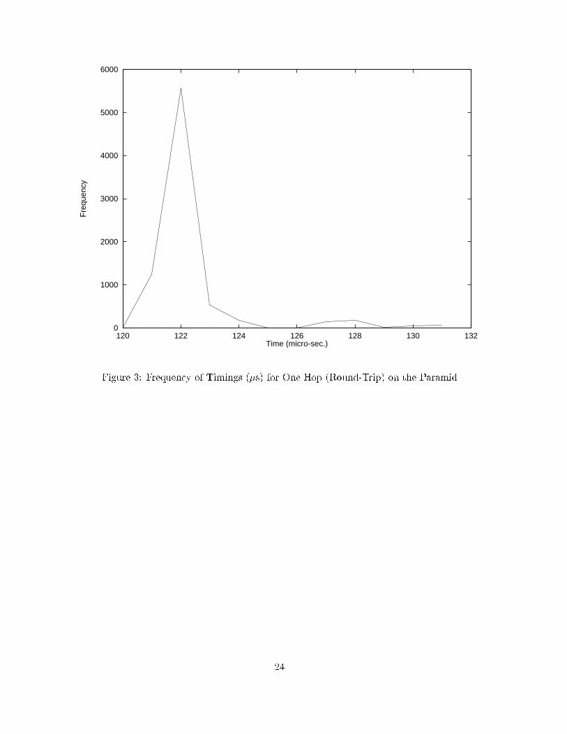
limited numbers of available processors, one of the nodes was placed in one test on the sameprocessor as the synchronization node. This should have distorted the results as the minimumjourney time was less than the recorded one hop time, but in practice the message orderingon the visualizer was not a�ected.The Paramid usually employs a virtual channel system but the underlying hardware isdependent on store-and-forward communication. Figure 3 is the result of measurements onan empty system when it will be seen that the round-trip message time distribution is indeedlong-tailed, though the lower `hump' may be caused by the low-priority process time-sliceinterrupt (every 1024�s) which makes some readings appear longer. The initiation algorithmwas run before the system settled into normal working, avoiding extraneous calculationsin later stages. The clocks were corrected in the initial stage, introducing an element ofconvergence into the estimate of the refresh time.6.2 ResultsA crude measure of overhead was made on the central node by recording (without clock driftadjustment) the time taken for synchronization, recording the trace and supplying a localclock. The overhead on other nodes will naturally be less. The timing breakdowns are givenin Table 1, which is for 1000 round-trip messages of approximately 200 bytes each. Notethat the results in the table are consistent since in some cases, discounting the �rst fourpulses at 0.1 second intervals, the synchronization manager was halted just before makinga last pulse. The overheads recorded refer to a particular total job size regime, as Figure 4shows that the �xed overhead becomes a much greater burden for shorter job sizes. Thecommunication overhead, aside from synchronization, was between 6% and 9%. The numberof synchronization pulses includes those made mostly over shorter intervals at initiation time.The number of messages is restricted so that the trace �le can be held entirely in main memory.Though no work, and a round-robin distribution of work with constant intervals were tried, inthis instance truncated and random quantized Gaussian distributions were employed for theworkloads (with mean per node work time equal to the variance). Experience of testing showed13

that using a Gaussian distribution was more likely to �nd errors in recording message times,though once the appropriate parameters had been set no errors occurred. We made use of anexisting post-mortem visualizer, Paragraph [34, 35], which unfortunately does not include atool to display tree topologies explicitly. Nevertheless, with the space-time diagram and usingour trace collection system we were able to examine di�ering characteristic behaviour of: asingle farm (Figure 5); a handwritten postcode recognition application involving three farms(Figure 6); a hybrid video encoder with three logical farms (Figure 7); and a face identi�cationapplication involving three farms (Figure 8).The sampling interval was set to 0.1 s, the clock drift to 10�5 and the minimum one hopjourney time for 1 byte was found to be 6:0 � 10�5 s. With these parameters the clocksbecame accurate after four synchronization pulses during an enforced quiescence for the eightprocessors used. By accurate is meant that Paragraph did not report any errors for the testruns. Fewer initial synchronization pulses always led to ordering errors. The maximum errorfor varying round-trip times can be calculated from equation 9 using the measured minimumround-trip time, 6:0� 10�5 s, a clock-drift of 10�5 s and a clock resolution of 10�6 s. With ameasured net bandwidth of approximately 16 MHz on the Paramid and with the diameter ofthe network only three, the maximum error for our set-up is well within a 0.5 ms boundary.After four timings, the refresh period was set once and for all. It would probably be toodisruptive to re-sample at a later time and would add to the complexity of the software.One must certainly not use a recursive method of �nding the refresh times (by using the lastrefresh time as a sample interval) as this would lead to errors spiralling upwards.7 ConclusionIf parallelization is to be used more commonly in engineering systems design, standard designmethodologies will be necessary. For continuous- ow embedded systems this methodologycan be based on the Pipeline Processor Farm model. The essential feature of the model isa number of farms each of which will have a central farmer process and subsidiary worker14

processes. Provision of the model will depend on integral support of performance evaluationtools for the particular application. A trace tool is one component of the toolkit and thispaper has described the design of the clock synchronization sub-system for that tool. Thedetailed design is a compromise between achieving accuracy and avoiding perturbation of theparallel application. At least three causes of perturbation can be isolated:� excess number of messages;� disturbance of the pattern of communication;� excess calculations to achieve the synchronization.In this design, by using one centrally-determined refresh time, the disruption to the pattern ofcommunication is limited to one regularly-occurring pulse. The selection of the refresh time isassisted by discarding inaccurate samples by a probabilistic criterion. Speci�cally, averagingby a median is used to �nd an estimate of real time. Local adjustments for the estimatedlocal clock drift between refresh pulses reduce the central computation as does the selectionof an iterative method of median calculation.For the class of algorithms of concern to us, targets for throughput and/or latency throughthe parallel system usually exist. If the targets are met while the clock synchronization is inplace then there may be no need to remove the monitoring apparatus from the productionmodel. The visualization would then represent a true re ection of the system giving con�dencein its correct working. The case study has shown that for jobs of a suitable duration on theParamid the time overhead from synchronization is a small percentage in time. In othercircumstances, one should consider perturbation analysis [36] after the event trace has beencollected. In fact, future work will investigate the post-processing of traces in order to provideinput to an analytic (queueing) model.15

AcknowledgementThis work was carried out under EPSRC research contract GR/K40277 `Portable softwaretools for embedded signal processing applications' as part of the EPSRC PSTPA (PortableSoftware Tools for Parallel Architectures) directed programme.
16

References[1] A. C�uhadar and A. C. Downton. Structured parallel design for embedded vision sys-tems: An application case study. In Proceedings of IPA'95 IEE International Conferenceon Image Processing and Its Applications, pages 712{716, July 1995. IEE ConferencePublication No. 410.[2] M. N. Edward. Radar signal processing on a fault tolerant transputer array. In T.SDurrani, W.A. Sandham, J.J. Soraghan, and S.M. Forbes, editors, Applications ofTransputers 3. IOS, Amsterdam, 1991.[3] S. Glinski and D. Roe. Spoken language recognition on a DSP array processor. IEEETransactions on Parallel and Distributed Systems, 5(7):697{703, 1994.[4] A-M Cheng. High speed video compression testbed. IEEE Transactions on ConsumerElectronics, 40(3):538{548, 1994.[5] M. H. Co�n. Parallel Programming A New Approach. Silicon Press, Summit, NJ, 1992.[6] A. C. Downton, R. W. S. Tregidgo, and A. Cuhadar. Top-down structured parallelisationof embedded image processing applications. IEE Proceedings I (Vision, Image, and SignalProcessing), 141(6):431{437, December 1994.[7] M. Fleury, H. P. Sava, A. C. Downton, and A. F. Clark. Designing and implementing asoftware template for embedded parallel systems. In C. R. Jesshope and A. V. Shafarenko,editors, UK Parallel'96, pages 163{180. Springer, London, 1996.[8] G. A. Geist, M. T. Heath, B. W. Peyton, and P. H. Worley. A user's guide to PICL:a portable instrumented communication library. Technical report, Oak Ridge NationalLaboratory, Oak Ridge, TN, USA, August 1990. Report ORNL/TM-11616.[9] L. Lamport. Time, clocks, and the ordering of events in a distributed system. Commu-nications of the ACM, 21(7):558{565, 1978.17

[10] M. Raynal and M. Singhal. Capturing causality in distributed systems. IEEE Computer,pages 49{56, February 1996.[11] L. J. Levrouw and K. M. R. Audenaert. Minimimizing the log size for execution replay ofshared-memory programs. In B. Buchberger and J. Volkert, editors, CONPAR'94-VAPPVI, pages 76{87. Springer, Berlin, 1994. Lecture Notes in Computer Science Volume 854.[12] L. Lamport and Melliar-Smith P. M. Synchronizing clocks in the presence of faults.Journal of the Association for Computer Machinery, 32(1):52{78, January 1985.[13] K. G. Shin and P. Ramanathan. Clock synchronization of a large multiprocessor system inthe presence of malicious faults. IEEE Transactions on Computers, 36(1):2{12, January1987.[14] T. K. Srikanth and S. Toueg. Optimal clock synchronization. Journal of the ACM,34(3):626{645, July 1987.[15] U. de Carlini and U. Villano. A simple algorithm for clock synchronization in transputernetworks. Software|Practice and Experience, 18(4):331{347, April 1988.[16] J. Lundelius and N. Lynch. An upper and lower bound for clock synchronization. Inform-ation and Control, 62(2-3):190{204, 1984.[17] A. Duda, G. Harrus, Y. Haddad, and G. Bernard. Estimating global time in distributedsystems. In 7th International Conference on Distributed Computer Systems, pages 299{306. IEEE, 1987.[18] W. Obel�oer, H. Willeke, and E. Maehle. Performance measurement and visualizationof multi-transputer systems with DELTA-T. In G. Haring and G. Kotsis, editors, Per-formance Measurement and Visualization of Parallel Systems, pages 119{143. Elsevier,Amsterdam, 1993.[19] K. Marzullo and S. Owicki. Maintaining the time in a distributed system. ACM OperatingSystem Review, 19(3):44{54, July 1983. 18

[20] N. W. Rickert. Non byzantine clock synchronization | a programming experiment.ACM Operating System Review, 22(1):73{78, January 1988.[21] H. Kopetz and W. Ochsenreiter. Clock synchronization in distributed real-time systems.IEEE Transactions on Computers, 36(8):933{940, August 1987.[22] U. Villano. Monitoring parallel programs running in transputer networks. In G. Haringand G. Kotsis, editors, Performance Measurement and Visualization of Parallel Systems,pages 67{96. Elsevier, Amsterdam, 1993.[23] J. Jiang, A. Wagner, and S. Chanson. Tmon: A real-time performance monitor fortransputer-based multicomputers. In D. L. Fielding, editor, Transputer Research andApplications 4, pages 36{45. IOS, Amsterdam, 1990.[24] T. H. Dunigan. Hypercube clock synchronization. Concurrency: Practice and Experience,4(3):257{268, May 1992.[25] R. Cole and C. Foxcroft. An experiment in clock synchronization. The Computer Journal,31(6):496{502, 1988.[26] E. Maillet and C. Tron. On e�ciently implementing global time for performance eval-uation on multiprocessor systems. Journal of Parallel and Distributed Computing,28(1):84{93, 1995.[27] D. L. Mills. On the accuracy and stability of clocks synchronized by the Network TimeProtocol in the Internet system. ACM Computer Communication Review, 20(1):65{75,January 1980.[28] D. L. Mills. Internet time synchronization: the Network Time Protocol. IEEE Transac-tions on Communications, 39(10):1482{1493, October 1991.[29] W. H. Press, B. P. Flannery, S. A. Teukolsky, and W. T. Vetterling. Numerical Recipesin C. C.U.P., Cambridge, UK, 1st edition, 1988.19

[30] D. E. Knuth. The Art of Computer Programming, volume 3/Sorting and Searching.Addison-Wesley, Reading, MA, 1973.[31] F. Cristian. A probabilistic approach to distributed clock synchronization. In Proceedingsof the Ninth IEEE International Conference on Distributed Computer Systems, pages288{296, June 1989.[32] Transtech Parallel Systems Corporation, 20, Thornwood Drive, Ithaca, NY, USA. TheParamid User Guide, 1993.[33] M. Atkins. Performance and the i860 microprocessor. IEEE Micro, pages 24{78, October1991.[34] M. T. Heath and J. A. Etheridge. Visualizing the performance of parallel programs.IEEE Software, 8(5):29{39, 1991.[35] I. Glendinning, V. S. Getov, S. A. Hellberg, and R. W. Hockney. Performance visual-isation in a portable parallel programming environment. In G. Haring and G. Kotsis,editors, Performance Measurement and Visualization of Parallel Systems, pages 251{275.Elsevier, Amsterdam, 1993.[36] A. D. Maholy, D. A. Reed, and H. A. G. Wijsho�. Performance measurement intrusionand perturbation analysis. IEEE Transactions on Parallel and Distributed Systems,3(4):433{450, July 1992.
20

List of Tables1 Timings (s) Recorded on the Central Node Using the Local Clock : : : : : : : 22List of Figures1 System Set-up on the Paramid with a PPF Arrangement : : : : : : : : : : : 222 Synchronization Signal Pattern : : : : : : : : : : : : : : : : : : : : : : : : : : 233 Frequency of Timings (�s) for One Hop (Round-Trip) on the Paramid : : : : 244 Overhead from Tracing on the Paramid : : : : : : : : : : : : : : : : : : : : : 255 Display for a Seven Worker Farm : : : : : : : : : : : : : : : : : : : : : : : : : 256 Display of the Postcode Application : : : : : : : : : : : : : : : : : : : : : : : 267 Display for H.263 : : : : : : : : : : : : : : : : : : : : : : : : : : : : : : : : : : 268 Display for Face Identi�cation Application : : : : : : : : : : : : : : : : : : : : 26
21

Wall-clock Sync. No. of sync. Overhead from Total % MeanTime Interval timings Syncs. Serving time Making trace overhead work time16.641 3.197 9 0.013 0.311 0.505 4.987 0.132.125 3.197 13 0.063 0.316 0.503 2.745 0.247.452 3.197 18 0.145 0.316 0.504 2.034 0.3109.040 3.197 37 0.097 0.294 0.505 0.822 0.7155.096 3.197 52 0.183 0.308 0.502 0.640 1.0309.957 3.197 100 0.321 0.306 0.504 0.365 2.0Table 1: Timings (s) Recorded on the Central Node Using the Local Clock
VCSVCS
VCS
Application
Program
Application
ProgramApplication
Program
RTEInterfaceprogram RTE
Interfaceprogram
RTERTE Interface
program Interfaceprogram
Application
Program
VCS
To the host
i860 i860
i860i860
Transputer
TransputerTransputer
Overlapped memory
RTE = Run-Time Executive
Farmer 2
Farmer 1
Worker 1 Worker 2
VCS = Virtual Channel System
Transputer
Figure 1: System Set-up on the Paramid with a PPF Arrangement22

Node 0
Node i ti
t0
Di measured by node 0
To(h) To(h) (minimum time over h hops)
r (time as measured by node i)
Correction message
giving offset + median offset
Node i measures time to correction
adjusting by estimated clock drift
Node 0’s estimate
Arrival
uncertainty
for time r.
Figure 2: Synchronization Signal Pattern
23
0
1000
2000
3000
4000
5000
6000
120 122 124 126 128 130 132
Fre
quen
cy
Time (micro-sec.)Figure 3: Frequency of Timings (�s) for One Hop (Round-Trip) on the Paramid
24

0
5
10
15
20
25
30
35
40
45
50
0 20 40 60 80 100 120 140 160
% T
race
Ove
rhea
d
Job Size (s)Figure 4: Overhead from Tracing on the Paramid
Figure 5: Display for a Seven Worker Farm25

Figure 6: Display of the Postcode Application
Figure 7: Display for H.263
Figure 8: Display for Face Identi�cation Application26