Design of a 450-passenger blended wing body aircraft for ...
10
Design of a 450-passenger blended wing body aircraft for active control investigations B Mohr 1 *, D Paulus 1 , H Baier 2 , and M Hornung 1 1 Institute of Aircraft Design, Technische Universita ¨t Mu ¨ nchen, Mu ¨ nchen, Germany 2 Institute of Lightweight Structures, Technische Universita ¨t Mu ¨ nchen, Mu ¨ nchen, Germany The manuscript was received on 16 May 2011 and was accepted after revision for publication on 19 September 2011. DOI: 10.1177/0954410011426031 Abstract: ACFA 2020 (active control for flexible aircraft) is a collaborative research project funded by the European Commission under the seventh research framework programme. The project deals with innovative active control concepts for 2020 aircraft configurations like the blended wing body (BWB) aircraft. The main objectives of ACFA are the design of a new ultra efficient 450 passenger BWB type aircraft as well as the provision of robust adaptive multi- channel control architectures for such aircraft. The objective of the newly designed controllers is an ambitious improvement of ride comfort and handling qualities, as well as load reduction on BWB type aircraft. Based on the attained load reduction, the structure of the 450-passenger aircraft can be resized with the goal of an ambitious weight saving for further improvement of fuel efficiency. Active control requirements influence the design process of control surfaces and overall aircraft design, respectively. Hence, the conventional aircraft design process had to be adapted to the new requirements. The aircraft design framework described in this article has proven its efficiency in the development of the ACFA BWB aircraft. Within a time period of 1 year, an airframe has been developed under the constraints of multiple domain requirements. This article presents the process and the results of the design activities of the BWB aircraft, which form the basis for a detailed concept analysis as well as the investigation of multiple-input multiple- output control architectures. Keywords: blended wing body, BWB, active control, aircraft design, ACFA 2020 1 PROJECT CONCEPT AND OBJECTIVES The Advisory Council for Aeronautics Research in Europe (ACARE) proposed the Strategic Research Agenda (SRA) in November 2001 and an updated ver- sion in March 2008. The SRA is the road map for real- izing the ‘ACARE vision 2020’ [1, 2], which aims at: (a) 50 per cent reduced fuel consumption and related carbon dioxide (CO 2 ) emissions per passenger- kilometer; (b) reduced perceived noise to one half of current average levels; (c) improvement of handling qualities and ride comfort. These ambitious goals can only be achieved through major changes in future aircraft configura- tions. Highly promising concepts with regard to improved fuel efficiency are blended wing body (BWB) aircraft configurations (i.e. tailless aircraft configurations with aerodynamic wing/fuselage blending). Low fuel consumption is mainly achieved by drag reduction, reduced structural weight, and through the significantly lower ratio of wetted area/ reference area for BWB aircraft compared to other configurations. Exterior noise signature can be reduced by a simplified high-lift system (morphing trailing edge) and by integrating the engines over the rear fuselage or in the airframe. Major design issues of such BWB-type aircraft have been recently *Corresponding author: Institute of Aircraft Design, Technische Universita ¨t Mu ¨ nchen, Boltzmannstrasse 15, 85748 Garching, Mu ¨ nchen, Germany. email: [email protected] 1513 Proc. IMechE Vol. 226 Part G: J. Aerospace Engineering at Technical University of Munich University Library on November 4, 2016 pig.sagepub.com Downloaded from
-
Upload
khangminh22 -
Category
Documents
-
view
0 -
download
0
Transcript of Design of a 450-passenger blended wing body aircraft for ...
Design of a 450-passenger blended wing bodyaircraft for active control investigationsB Mohr1*, D Paulus1, H Baier2, and M Hornung1
1Institute of Aircraft Design, Technische Universitat Munchen, Munchen, Germany2Institute of Lightweight Structures, Technische Universitat Munchen, Munchen, Germany
The manuscript was received on 16 May 2011 and was accepted after revision for publication on 19 September 2011.
DOI: 10.1177/0954410011426031
Abstract: ACFA 2020 (active control for flexible aircraft) is a collaborative research projectfunded by the European Commission under the seventh research framework programme. Theproject deals with innovative active control concepts for 2020 aircraft configurations like theblended wing body (BWB) aircraft. The main objectives of ACFA are the design of a new ultraefficient 450 passenger BWB type aircraft as well as the provision of robust adaptive multi-channel control architectures for such aircraft. The objective of the newly designed controllersis an ambitious improvement of ride comfort and handling qualities, as well as load reduction onBWB type aircraft. Based on the attained load reduction, the structure of the 450-passengeraircraft can be resized with the goal of an ambitious weight saving for further improvement offuel efficiency. Active control requirements influence the design process of control surfaces andoverall aircraft design, respectively. Hence, the conventional aircraft design process had to beadapted to the new requirements. The aircraft design framework described in this article hasproven its efficiency in the development of the ACFA BWB aircraft. Within a time period of 1 year,an airframe has been developed under the constraints of multiple domain requirements. Thisarticle presents the process and the results of the design activities of the BWB aircraft, which formthe basis for a detailed concept analysis as well as the investigation of multiple-input multiple-output control architectures.
Keywords: blended wing body, BWB, active control, aircraft design, ACFA 2020
1 PROJECT CONCEPT AND OBJECTIVES
The Advisory Council for Aeronautics Research in
Europe (ACARE) proposed the Strategic Research
Agenda (SRA) in November 2001 and an updated ver-
sion in March 2008. The SRA is the road map for real-
izing the ‘ACARE vision 2020’ [1, 2], which aims at:
(a) 50 per cent reduced fuel consumption and related
carbon dioxide (CO2) emissions per passenger-
kilometer;
(b) reduced perceived noise to one half of current
average levels;
(c) improvement of handling qualities and ride
comfort.
These ambitious goals can only be achieved
through major changes in future aircraft configura-
tions. Highly promising concepts with regard to
improved fuel efficiency are blended wing body
(BWB) aircraft configurations (i.e. tailless aircraft
configurations with aerodynamic wing/fuselage
blending). Low fuel consumption is mainly achieved
by drag reduction, reduced structural weight, and
through the significantly lower ratio of wetted area/
reference area for BWB aircraft compared to other
configurations. Exterior noise signature can be
reduced by a simplified high-lift system (morphing
trailing edge) and by integrating the engines over
the rear fuselage or in the airframe. Major design
issues of such BWB-type aircraft have been recently
*Corresponding author: Institute of Aircraft Design, Technische
Universitat Munchen, Boltzmannstrasse 15, 85748 Garching,
Munchen, Germany.
email: [email protected]
1513
Proc. IMechE Vol. 226 Part G: J. Aerospace Engineering
at Technical University of Munich University Library on November 4, 2016pig.sagepub.comDownloaded from

investigated, which represent a solid basis for design
considerations of the active control for flexible air-
craft (ACFA) BWB [3–6]. The challenge created by
the complex active control system for BWB-type air-
craft has been identified, but not yet addressed in
detail. Therefore, the two main challenges investi-
gated within the ACFA 2020 project are described in
the following sections.
1.1 Pre-design of the ACFA 2020 aircraftconfiguration
Since the biggest market share in long haul flights is
taken by mid-size aircraft (400–500 passengers), a
new ultra-efficient 450 passenger tailless composite
aircraft with aerodynamic wing/fuselage blending is
devised within the ACFA 2020 project. For minimum
exterior noise signature, the engines are mounted
over the rear fuselage. The choice for this layout was
supported by results of a detailed analysis of shielding
engine noise with the airframe structure [5, 7]. Based
on the multiple-input multiple-output (MIMO) con-
trol strategy results obtained, the structure of the
ACFA 2020 aircraft configuration will be resized to
demonstrate the potential weight benefit achieved
by active control. The contribution to the ACARE
emission reduction goals is investigated at the end
of the project.
1.2 Providing solutions for the active control
system
Active control systems for the alleviation of structural
vibrations as well as of gust and manoeuvre loads
have been investigated for conventional aircraft con-
figurations [8, 9]. Such active control systems are an
important means for the reduction of critical loads as
well as for the improvement of ride comfort and
handling qualities. Load reduction increases aircraft
efficiency by reducing structural weight. Thus, it is
self-evident to incorporate active structural control
into future aircraft configurations. However, BWB
type aircraft set completely new challenges with
regard to complexity of control algorithms, control
design and optimization, as well as control system
architecture. Instead of various single-channel or
single-input-single-output controllers, a highly cou-
pled multi-channel or MIMO controller is required.
Thus, the main objective of ACFA 2020 is to provide
robust as well as adaptive MIMO architectures for
active control of BWB-type aircraft. The aim of pro-
viding solutions for the required active MIMO control
on BWB-type aircraft is to get closer to the realization
of a highly efficient future aircraft configuration, and
also to make BWB-type aircraft even more efficient by
reducing structural weight through active control. An
additional objective is to make BWB aircraft more
passenger friendly by increasing ride comfort with
the use of active control.
This article possesses the following structure. After
the introduction to the overall project context and
its objectives, the design for active control and the
inherent challenges are discussed in section 2.
Subsequently, the aerodynamic design and especially
the airfoils and control surface calculations are pre-
sented in section 3. Section 4 presents structural
weight estimations and the comparison to similar
designs precedes section 5 on performance, which
describes the results of a takeoff (TO) and landing
analysis as well as mission performance calculations.
Concluding this article, the findings are summarized
and an outlook with regard to the ACARE vision and
ACFA project is discussed in section 6.
2 DESIGN FOR ACTIVE CONTROL
The ACFA aircraft design activities focus on active
control technology (ACT) as a design principle for
future aircraft configurations. ACT stands for the
use of controller technologies that enable improved
flight performance and possible beneficial effects on
the overall aircraft design (e.g. direct lift control or
flutter control). ACT has become a standard for mil-
itary aircraft configurations which are highly unstable
but is still rare in civil aircraft design. The main rea-
sons for this are the rather complex control systems
and the respective certification issues. However,
diminishing fuel resources make economic flying
more important and ACT is one means to improve
aircraft efficiency. The ACT mechanisms for improved
payload and range are shown in Fig. 1.
Possible ACT applications are given as follows:
(a) reduction of static longitudinal stability margin;
(b) manoeuvre and gust load alleviation;
Fig. 1 Contribution of active control to improved pay-load and range (adapted from [10])
1514 B Mohr, D Paulus, H Baier, and M Hornung
Proc. IMechE Vol. 226 Part G: J. Aerospace Engineering
at Technical University of Munich University Library on November 4, 2016pig.sagepub.comDownloaded from

(c) adaptive wing;
(d) flutter damping;
(e) direct lift and lateral force control.
By integrating ACT principles, the traditional air-
craft design process is changed. The design of control
surfaces and the respective controllers is integrated in
the iterative overall aircraft configuration process
(Fig. 2). In conventional aircraft design, the influence
of control surface design on wing and stabilizer
dimensions as well as structural layout has not been
closely coupled. If ACT principles are integrated more
deeply into the overall design process, the possibility
to perform interdisciplinary studies has to be pro-
vided. Best results are achieved if ACT requirements
are included in the design requirements as early as
possible [11]. It is obvious that a greater level of inter-
disciplinary tasks requires a high level of communi-
cation and well-defined interfaces between project
partners across Europe. The results of the newly
defined ACT aircraft design process are presented in
the following sections.
3 AERODYNAMIC ANALYSIS
3.1 Airfoils aerodynamics
BWB configurations require special airfoils that differ
from standard profiles in many ways. The profile for
the centre section has to provide the space for the
cabin and must therefore have ample thickness.
The thickness, however, is limited by aerodynamic
performance considerations, especially wave drag.
The thickness of the profile also influences the
length of the centre body, which has an influence on
friction drag and rotation clearance at TO. Generally,
relatively low lift coefficients are required at the
centre body and higher lift coefficients at the outer
wing. The aerodynamic model for the identification
of the twist distribution of the configuration was
established with the linear-vorticity stream function
panel method implemented in XFLR5 [12]. The
research project multidisciplinary optimization of a
BWB investigated several span loading scenarios
and concluded that an averaged elliptic/triangular
distribution enables the best aerodynamic perfor-
mance for blended wings measured by the L/D ratio
or the total drag at the design cruise condition [13].
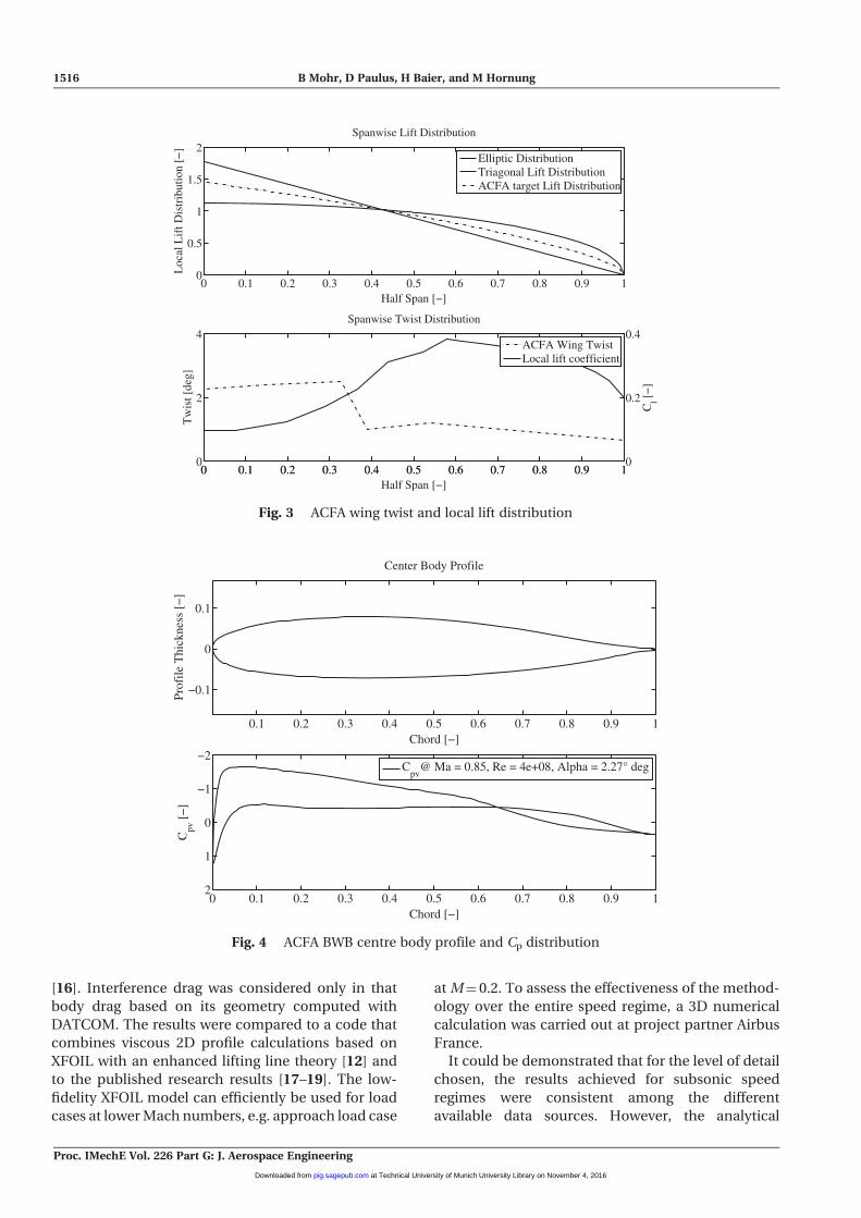
Therefore, the twist distribution ACFA BWB was
adjusted to the proposed spanwise lift distribution
(Fig. 3). For a known chord length, local lift and CL
upon alpha distribution, it is possible to determine
local incidence angles at a discrete number of two-
dimensional (2D) profiles. As the overall geometry is
three-dimensional (3D), the calculated twist distribu-
tion is not necessarily consistent with the target lift
distribution if analysed with the panel code again.
With few iterative steps, local twist has been manually
refined until the spanwise twist and target lift distri-
bution was sufficiently met with airfoils developed,
especially for the ACFA BWB.
Figures 4 and 5 show the final profiles of the centre
body and the outer wing as well as respective pressure
distribution at incidence angles at the design point.
Clearly visible are trailing edge upwards movement
in the centre body for trim reasons and the super-
critical airfoil at the outer wing for shock-delaying
characteristics.
Flight stability was optimized iterating wing sweep
for a given lift and a given surface with an evolution-
ary algorithm. The objective function of the optimi-
zation aimed to equally maximize glide ratio and
minimize the longitudinal positive moment coeffi-
cient Cm. Because the induced drag penalty of a pos-
itive pitching moment coefficient is much lower at
the centre body than at the outer wing, the centre
body profile has a positive moment coefficient. At
the outer wing, the moment coefficient is slightly neg-
ative to enable a stable configuration.
3.2 Aircraft aerodynamics
Lift and drag calculations to study the aerodynamics
of the BWB at different angles of attacks and flight
altitudes were conducted using a combination of sev-
eral empirical methods. For drag analysis of the ACFA
BWB, DATCOM [14] was used to analyse the effects of
form and lift-induced drag. To account for the differ-
ent airfoils used in the centre and outer wing sections,
the wing was divided into five panels with corrections
being made for Reynolds number and lifting surface
geometry at subsonic speeds. Skin friction drag was
added as discussed in Schemensky [15]. Drags due to
twist or crank influences were taken from TorenbeekFig. 2 ACT aircraft design process (adapted from [10])
Design of a 450-passenger blended wing body aircraft for active control investigations 1515
Proc. IMechE Vol. 226 Part G: J. Aerospace Engineering
at Technical University of Munich University Library on November 4, 2016pig.sagepub.comDownloaded from
[16]. Interference drag was considered only in that
body drag based on its geometry computed with
DATCOM. The results were compared to a code that
combines viscous 2D profile calculations based on
XFOIL with an enhanced lifting line theory [12] and
to the published research results [17–19]. The low-
fidelity XFOIL model can efficiently be used for load
cases at lower Mach numbers, e.g. approach load case
at M¼ 0.2. To assess the effectiveness of the method-
ology over the entire speed regime, a 3D numerical
calculation was carried out at project partner Airbus
France.
It could be demonstrated that for the level of detail
chosen, the results achieved for subsonic speed
regimes were consistent among the different
available data sources. However, the analytical
0 0.1 0.2 0.3 0.4 0.5 0.6 0.7 0.8 0.9 10
2
4
Tw
ist [
deg]
Half Span [−]
Spanwise Twist Distribution
0 0.1 0.2 0.3 0.4 0.5 0.6 0.7 0.8 0.9 10
0.2
0.4
Cl [
−]
ACFA Wing TwistLocal lift coefficient
0 0.1 0.2 0.3 0.4 0.5 0.6 0.7 0.8 0.9 10
0.5
1
1.5
2
Half Span [−]
Loc
al L
ift D
istr
ibut
ion
[−]
Spanwise Lift Distribution
Elliptic DistributionTriagonal Lift DistributionACFA target Lift Distribution
Fig. 3 ACFA wing twist and local lift distribution
0.1 0.2 0.3 0.4 0.5 0.6 0.7 0.8 0.9 1
−0.1
0
0.1
Chord [−]
Prof
ile T
hick
ness
[−
]
Center Body Profile
0 0.1 0.2 0.3 0.4 0.5 0.6 0.7 0.8 0.9 1
−2
−1
0
1
2
Chord [−]
Cpv
[−
]
Cpv
@ Ma = 0.85, Re = 4e+08, Alpha = 2.27° deg
Fig. 4 ACFA BWB centre body profile and Cp distribution
1516 B Mohr, D Paulus, H Baier, and M Hornung
Proc. IMechE Vol. 226 Part G: J. Aerospace Engineering
at Technical University of Munich University Library on November 4, 2016pig.sagepub.comDownloaded from

computation of transonic wave drag effects proved to
be inaccurate for several reasons. Expressions of
higher order are usually neglected in analytical for-
mulas, although their influence is significant in the
transonic regime. The complexity of the different
unconventional cross-sections is only inaccurately
reflected with conventional methods which often
ignore wave-drag-due-to-lift effects.
Analytical methods such as the Lock formula
described and adapted by Malone and Mason [20]
for the estimation of wave drag effects could thus
only approximate high accuracy codes. Figure 6
indicates the results achieved with the empirical
approaches above and the final values of compress-
ibility drag counts used for the ACFA BWB design.
Further investigations on transonic aerodynamics
being compatible with BWB applications are neces-
sary if the subsequent design process is not to revert
to 3D computational fluid dynamics (CFD) codes in
the early phases of development.
3.3 Control surface design
Blended wing configurations feature an especially
high coupling between flap deflections and aircraft
movements in all three axes. As a result, multi-
objective control surfaces are required for flight con-
trol and active gust and manoeuvre load alleviation.
The main challenge is to provide sufficient yaw
control and stability in the absence of a vertical tail
if one engine is inoperative (OEI). This case is the
dominant criterion for the pre-sizing of yaw control
devices for the ACFA configuration with two top-rear
high-bypass turbo fan engines and winglets.
For all configuration updates during the design
loop, a flutter analysis has been performed as a
basis for subsequent ACT investigations. Different
flying velocities have been considered for weights
ranging from maximum zero fuel weight to maximum
takeoff weight (MTOW). Lumped masses were used
for modelling payload, equipment, systems, and
fuel. The integrated aerodynamic model has been
developed with NASTRAN and the doublet lattice
method has been used for considering the unsteady
aerodynamics. A reference target envelope has been
defined from the maximum operative speed (VMO)
(VMO¼ 340 knots equivalent airspeed; KEAS). Design
dive speed (VD) is 25 per cent higher than VMO and
calculates to 425 KEAS [21]. Finally, the flutter refer-
ence limit value is 489 KEAS (1.15 VD) [22]. The modal
analysis showed a high number of modes in a quite
low frequency (up to 20 Hz). Classical modes, such as
wing bending and wing torsion, were well identified.
A further structural upgrade of the model became
necessary for a more realistic aircraft design. A para-
metric frequencies analysis has been performed with
a progressive reduction of the winglet length, differ-
ent positioning of the winglet, the addition of masses
on the wing leading edge, and the increase of the
outer wing skin thickness at project partners
ALENIA and ONERA. In consequence, further struc-
tural models have been developed in order to remedy
0.1 0.2 0.3 0.4 0.5 0.6 0.7 0.8 0.9 1
−0.1
0
0.1
Chord [−]
Prof
ile T
hick
ness
[−
]
Outer Wing Profile
0 0.1 0.2 0.3 0.4 0.5 0.6 0.7 0.8 0.9 1
−1
−0.5
0
0.5
1
1.5
Chord [−]
Cpv
[−
]
Cpv
@ Ma = 0.85, Re = 3e+07, Alpha = 0.65 deg
Fig. 5 ACFA BWB wing profile and Cp distribution
Design of a 450-passenger blended wing body aircraft for active control investigations 1517
Proc. IMechE Vol. 226 Part G: J. Aerospace Engineering
at Technical University of Munich University Library on November 4, 2016pig.sagepub.comDownloaded from

the critical aspects previously found. The final version
of the model showed the desired separation between
wing bending and wing torsion frequencies, which
has a great importance for flutter aspects. The final
winglet design led to the addition of �45� ribs in the
outer part of the wing, in order to increase the torsion
stiffness of the wing. Furthermore, a winglet length
reduction and an appropriate variation in the overall
wing thickness have been applied. As the winglet
height had to be reduced, the usage of winglets as
the only source for yaw control became insufficient
for handling the OEI case. To add the necessary
yawing moment, crocodile flaps have been intro-
duced in the very outer part of the wing. The prelim-
inary sizing of the control surfaces presented in this
study is subject to further possible modifications
from subsequent investigations on active control of
the aircraft: The detailed design of an all-composite,
all-electric, and morphing trailing edge device and
respective modelling and testing is described in
Wildschek et al. [23]. The design of a preElter for lon-
gitudinal motion control of a large flexible BWB air-
craft is presented in Westermayer et al. [24]. The final
control surface layout will be published in subse-
quent publications of the ACFA project.
4 WEIGHT ESTIMATION
Due to the fact that no full-scale BWB has yet been
built, uncertainties remain in the design efforts. The
problem of realistic weight estimation for flying wing
configurations has been discussed by Bradley [25]
and Howe [26] in their papers in 2004 and 2001,
respectively. The stress level in BWB fuselages is an
order of magnitude higher than for cylindrical pres-
surized fuselages because internal pressure primarily
results in bending stress instead of skin-membrane
stress [27]. Robust empirical methods have not been
established yet. Hence, to keep the uncertainties as
low as possible, high-fidelity finite element (FE)
models have been designed from the early project
phases onwards. Especially, the unconventional
structural elements like the fuselage and the wing-
to-body fairing were parametrically build up to
allow for design changes. Conventional structural ele-
ments like outer wing, systems, furnishings, and land-
ing gear were calculated according to the federal
aviation regulations (JAR) sections or derived from
empirical databases of existing aircraft [28].
The BWB transports 34.8 tons of operator items and
a payload of 49.5 tons. Fuel weight has been itera-
tively assessed with the Breguet/Leduc range equa-
tion. Table 1 shows the main weight parameters and a
comparison with other recent BWB designs. The
weight fraction operator empty weight (OEW)/
MTOW influences fuel burn. Most BWBs show
higher values than comparable conventional aircraft
mainly as a result from structural reinforcements due
to non-tubular cross-sections. Regarding mission
performance, this penalizing effect is offset by the
higher aerodynamic efficiency of BWB configura-
tions. However, discrepancies between BWB config-
urations regarding the ratio between payload and
structural weight are evident.
1 2 3 4 5 6 7 8 9 10 11
x 10−3
0.15
0.17
0.19
0.21
0.23
0.25
0.27
0.29
0.31
0.33
0.35
CDwave
[−]
CL [
−]
Compressibility Drag @ Mach = 0.85
ACFA consortiumLock
Fig. 6 Comparison of empirical transonic drag estimation methods
1518 B Mohr, D Paulus, H Baier, and M Hornung
Proc. IMechE Vol. 226 Part G: J. Aerospace Engineering
at Technical University of Munich University Library on November 4, 2016pig.sagepub.comDownloaded from

5 PERFORMANCE
5.1 TO and landing
Like conventional aircraft, BWBs have to meet FAR
safety regulations and land on conventional airfields.
Takeoff field length and landing field length as well as
glide path angles influence the design of the high lift
devices. In the absence of a tail to counteract pitching
moments resulting from trailing edge control surface
deflection, these surfaces cannot be used as conven-
tional flaps. The moment required for rotation during
TO is generated by upwardly deflected trailing edge
flaps to counteract pitch (down) generated by engine
thrust. At high angles of attack, flow separation fur-
ther upstream can lead to low intake or heteroge-
neous pressures and thus decrease thrust output.
This issue needs to be further examined in a detailed
analysis of the TO performance. Trailing edge devices
are sized by trim requirements rather than by high lift
requirements [17]. This fact results in lower
maximum lift coefficients and lower wing loading.
The maximum lift coefficient of a BWB aircraft is
achieved at rather high angles of attack. As a result,
the controllability of the BWB aircraft at low speeds is
a crucial issue for the control surface design and the
assessment of TO and landing speeds (Fig. 7). To
determine these speeds, VMC (minimum control cal-
ibrated airspeed) has to be assessed. According to CS
25.149 (minimum control speed), it must be possible
to prevent a heading change of more than 20� at VMC
at TO [31]. To cope with this requirement, several
geometric alternatives of winglet rudder and split
ailerons and their respective derivatives have been
computed according to DATCOM to identify a VMC
of 113 knots with a split ailerons inner limit at 75 per
cent span. The solution was accepted because corre-
sponding bank and sideslip angles are below the
required limits (’¼ 2.3� and �¼ 10.1�) and the BWB
VMC is very similar to the VMC of a conventional
aircraft. Furthermore, the BWB achieves the 2.4 per
cent climb slope in a takeoff go around phase at 1.13
VS1g and the climb gradient achieved is 4.1 per cent
with 45� split ailerons deflection and 123 lbf nominal
engine thrust [32].
5.2 Cruise analysis: Airframe/engine matching
The detailed analysis of the mission performance
enables the refinement and optimization of the over-
all aircraft design. A crucial step towards the latter is
to match aerodynamic performance and engine size
for maximum range cruise (MRC) with maximum fuel
efficiency. Figure 8 depicts the results of the calcula-
tions and thus provides a graphical means to
200 220 240 260 280 300 320 340 360 380 400105
110
115
120
125
130
135
140
145
150
← OEW ← OEW + 75%PL ← MZFW ← MLW
VMCA
1.1 x VMCA
1.23 x VS1g →Minimum approach speed
← 1.13 x VS1gMinimum TO speed @35ft
VLS = 142knts @ MLW
Aircraft Weight [t]
Cal
ibra
ted
Air
Spe
ed [
kts]
Landing and TakeOff speed limits
Fig. 7 BWB takeoff and landing speed determination chart
Table 1 BWB configurations and respective weight
parameters
ConfigurationOEW(t)
Payload(t)
MTOW(t)
OEW/MTOW
ACFA BWB 225 50 401 0.56SAX40 BWB [5] 208 52 333 0.62Boeing BWB-450 [17] 187 89 373 0.50GbD BWB [29] 207 86 430 0.48MOB BWB [4] 137 113 371 0.37VELA 2 BWB [6] 406 103 777 0.52NACRE FW-1 [3] 357 71 700 0.51Boeing 747-400 [30] 179 67 397 0.45
Design of a 450-passenger blended wing body aircraft for active control investigations 1519
Proc. IMechE Vol. 226 Part G: J. Aerospace Engineering
at Technical University of Munich University Library on November 4, 2016pig.sagepub.comDownloaded from

determine how the current engine design fits the air-
frame aerodynamics. If maximum glide ratio and
minimum specific fuel consumption match at a cer-
tain altitude, MRC is achieved. The vertical flight pro-
file can be derived from the underlying data set and
be used as input for the mission analysis and the
design goal: minimization of fuel burn on the
7200 nm mission.
6 CONCLUSIONS AND PERSPECTIVE
6.1 Conclusions
In this article, the key results from the incorporated
ACT aircraft design process are presented. Especially,
the inherent problems of BWB designs like profile
selection, stability margin, and TO performance
have been discussed. Due to the unconventional
aircraft structural layout, high-fidelity FE models
were used from the early phases. The investigation
of compressible aerodynamics, i.e. changing posi-
tions of the aerodynamic centre or TO considerations
revealed the need for robust methods in the available
tool chain. It can be recommended that for future
investigations high-fidelity CFD codes may be used
from early project phases onwards. However, the pro-
posed design process proved its efficiency during a
resizing effort of the winglet. The overall aircraft
design finally met all the stated requirements and it
presents the baseline configuration for ACT investi-
gation within the ACFA consortium.
6.2 Contribution to ACARE vision
The implementation of new aircraft configurations
like blended wings is associated with high technolog-
ical and economical risks. As a result, the benefits of
blended wing configurations have to be significant to
be pursued; 50 per cent fuel reduction and related
CO2 emissions per passenger-kilometre are stated as
goals in the ACARE vision 2020. To find a reference
aircraft for a meaningful comparison with regard to
‘fuel reduction’ is rather intricate. As every aircraft
has its own design point, it is not adequate to com-
pare two different aircraft on one mission (payload/
range combination). The results will vary if the design
point of one aircraft or the other is considered.
However, several comparisons of fuel efficiency
(fuel burn per PAX per nautical mile) between
BWB-type aircraft and comparable conventional con-
figurations can be found in literature [29, 17]. These
comparisons have been calculated at the respective
design point of the BWB aircraft and engine technol-
ogy levels of the respective entry-into-service date are
assumed (Table 2)
The SRA goal of reducing CO2 emissions by 50 per
cent per passenger-kilometre assumes that new air-
frames can contribute 20–25 per cent, new engine
technologies 15–20 per cent, and air traffic manage-
ment 5–10 per cent [2]. The comparison above shows
that the higher aerodynamic efficiency of the BWB
aircraft significantly contributes to reduced CO2
emissions and thus lies within the SRA goals. To sub-
stantiate the beneficial effects of blended wings, the
0.51
0.515
0.52
0.525
0.53
Spec
ific
Fue
l Con
sum
ptio
n SF
C [
kg/h
daN
]
Aircraft Weight [t]
ACFA BWB − Aircraft Engine Matching Graph
Glid
e R
atio
E [
−]
280 300 320 340 360 380 400
22.5
23
23.5
24
24.5
E(33kft)E(35kft)E(37kft)E(39kft)E(41kft)
SFC(33kft)SFC(35kft)SFC(37kft)SFC(39kft)SFC(41kft)
Fig. 8 Airframe/engine matching graph
1520 B Mohr, D Paulus, H Baier, and M Hornung
Proc. IMechE Vol. 226 Part G: J. Aerospace Engineering
at Technical University of Munich University Library on November 4, 2016pig.sagepub.comDownloaded from

BWB should be analysed in detail within the current
air traffic network.
6.3 Contribution to the ACFA 2020 project
Thisarticle describes the sizing process of the prelim-
inary BWB aircraft configuration which represents
the basis of succeeding ACFA investigations. The pos-
sibility of resizing the aircraft structure with active
control mechanisms has not been carried out so far.
The potential weight benefits resulting from active
control on blended wings are to be released in
successive publications. The current configuration,
however, enabled the investigation of ACT principles
and a framework of a new design process was suc-
cessfully established. The efficiency of the proposed
aircraft design framework was proven during a highly
interactive effort to resize the winglet and respective
control surfaces. Although minor design issues
remain unsolved, the current configuration seems
highly attractive for further studies as a very promis-
ing overall aircraft concept (Fig. 9).
ACKNOWLEDGEMENTS
The authors thank all ACFA 2020 partners for their
contributions. Moreover, the authors are grateful to
R. Maier and A. Wildscheck from EADS-IW as well as
J.-J. Mirat and T. Salmon from Airbus France for their
continuous support. The authors also thank all the
participating colleagues from Technische Universitat
Munchen, namely K. Ploetner, C. Roessler, and
B. Brueckner, as well as F. Stroscher and O. Petersson.
FUNDING
This study was supported by European Commission
within the seventh Research Framework Programme
[grant agreement no. ACP7-GA-2008-213321].
� TUM – Prof. Mirko Hornung 2011
REFERENCES
1 Office for Official Publications of the EuropeanCommunities. European aeronautics: a vision for2020, meeting society’s needs and winning global lead-ership, Luxembourg, 2001.
2 ACARE - Advisory Council for Aeronautics Research inEurope. 2008 addendum to the strategic researchagenda, Belgium, ACARE, Brussels, 2008.
3 Gall, P. E. New Aircraft Concepts Research (NACRE).Aeronautics Days, Airbus S.A.S. Vienna, Austria, 19–21June 2006.
4 Morris, A., Arendsen, P., LaRocca, G., Laban, M.,Voss, R., and Honlinger, H. MOB – a European projecton multidisciplinary design optimization. InProceedings of the 24th international congress of theaeronautical sciences, Yokohama, Japan, 29 August–3September 2004.
5 Hileman, J. I., Spakovszky, S. Z., and Drela, M.Airframe design for ‘‘silent aircraft’’. In Proceedingsof the 45th AIAA aerospace sciences meeting and exhi-bit, Reno, Nevada, United States of America, 8–11January 2007, paper no. AIAA 2007-0453 (AmericanInstitute of Aeronautics and Astronautics, Reston,Virginia).
6 Kresse, N. VELA- Very Efficient Large Aircraft, A FP5project to enhance the knowledge on BWB configura-tions. Aeronautics Days, Vienna, Austria, 19–21 June2006.
7 Ricouard, J., Davy, R., Loheac, P., Moore, A., andPiccin, O. ROSAS wind tunnel test campaign dedi-cated to unconventional aircraft concepts study. InProceedings of the 10th AIAA/CEAS AeroacousticsConference, Manchester, UK, 10–12 May 2004, paperno. AIAA-2004-2867 (American Institute ofAeronautics and Astronautics, Reston, Virginia).
8 Konig, J. The European R&T platform AWIATOR:bringing new aircraft technologies into the air.Aeronautics Days, Vienna, Austria, 19–21 June2006.
9 Kordt, M. MODYAS – Multi Objective DynamicAircraft Synthesis, Airbus Operations GmbH,Germany, Hamburg, 2008.
Table 2 Comparison between BWB and conventional aircraft configurations
Configuration comparison Payload (kg) Range (nm) � Block fuel
ACFA BWB/B747-400 49 350 7200 24% Less for BWBGdB BWB/Conventional AC [29] 86 000 6750 23% Less for BWBBWB-450/Airbus A380-700 [17] 45 720 8700 32% Less for BWB
Fig. 9 Rendering of the ACFA BWB configuration
Design of a 450-passenger blended wing body aircraft for active control investigations 1521
Proc. IMechE Vol. 226 Part G: J. Aerospace Engineering
at Technical University of Munich University Library on November 4, 2016pig.sagepub.comDownloaded from

10 Weise, K. Anwendung von Active Control beiVerkehrsflugzeugen, MBB GmbH, Germany,Hamburg, 1980.
11 Moorhouse, D. J. Flight control design best practicesrelative to active control technology. In Proceedingsof the RTO AVT Symposium on Active control tech-nology for enhanced performance operational capa-bilities of military aircraft, land vehicles and seavehicles, Braunschweig, Germany, 8–11 May 2000,pp. 25-1–25-8.
12 XFLR5, Analysis tool for airfoils, wings and planesoperating at low Reynolds numbers, SoftwarePackage, ver. 6.02, Available from http://xflr5.sour-ceforge.net/xflr5.htm (accessed 5 January 2010).
13 Qin, N., Vavalle, A., and Moigne, A. L. Spanwise liftdistribution for blended wing body aircraft. J. Aircr.,2005, 42(2), 356–365.
14 Williams, J. E. and Vukelich, S. R. The USAF stabilityand control digital dATCOM. Volume I. Users manual,AFFDL-TR-79-3032, Air Force Flight DynamicsLaboratory, vol. 1, 1979.
15 Schemensky, R. T. Development of an empiricallybased computer program to predict the aerody-namic characteristics of aircraft, AFFDL-TR-73-144,Air Force Flight Dynamics Laboratory, 1973.
16 Torenbeek, E. Synthesis of subsonic airplane design:an introduction to the preliminary design of subsonicgeneral aviation and transport aircraft, with empha-sis on layout, aerodynamic design, propulsion andperformance, 1982 (Springer, AZ Dordrecht, TheNetherlands).
17 Liebeck, R. H. Design of the blended wing body sub-sonic transport. J. Aircr., 2004, 41(1), 10–25.
18 Diedrich, A., Hileman, J., Tan, D. Willcox, K., andSpakovszky, Z. Multidisciplinary design and optimi-zation of the silent aircraft. In Proceedings of the44th AIAA aerospace sciences meeting and exhibit,Reno, Nevada, United States of America, 9–12January 2006, paper no. AIAA 2006-1323 (AmericanInstitute of Aeronautics and Astronautics, Reston,Virginia).
19 Leifsson, L., Mason, W., Schetz, J., Grossman, B.,and Haftka, R. Multidisciplinary design optimiza-tion of low-airframe-noise transport aircraft. InProceedings of the 44th AIAA aerospace sciences meet-ing and exhibit, Reno, Nevada, USA, 9–12 January2006, paper no. AIAA 2006-230 (American Instituteof Aeronautics and Astronautics, Reston, Virginia).
20 Malone, B. and Mason, W. H. Multidisciplinary opti-mization in aircraft design using analytic technologymodels. J. Aircr., 1995, 32(2), 431–438.
21 European Aviation Safety Agency (EASA). CS-25.335design airspeeds (b), European Aviation SafetyAgency, Belgium, Brussels, 2003.
22 European Aviation Safety Agency (EASA). CS/AMC-25.307 proof of structure, European Aviation SafetyAgency, Belgium, Brussels, 2003.
23 Wildschek, A., Havar, T., and Plotner, K. An all-composite, all-electric, morphing trailing edge
device for flight control on a blended-wing-body air-liner. J. Aerosp. Eng., 2010, 224(1), 1–9.
24 Westermayer, C., Schirrer, A., Hemedi, M., andKozek, M. An H1 full information approach forthe feedforward controller design of a large BWBflexible aircraft. In Proceedings of the 4th EuropeanConference for Aerospace sciences (EUCASS), paperno. 658. Saint Petersburg, Russia, 4–8 July 2011.
25 Bradley, K. A sizing methodology for the conceptualdesign of blended-wing-body transports, NASA/CR-2004-213016, The National Aeronautics and SpaceAdministration, Washington, D.C., 2004.
26 Howe, D. Blended wing body airframe mass predic-tion. Proc. IMechE, Part G: J. Aerospace Engineering,2001, 215(6), 319–331.
27 Mukhopadhyay, V. Blended-Wing-Body (BWB)fuselage structural design for weight reduction. InProceedings of the 46th AIAA/ASME/ASCE/AHS/ASCstructures, structural dynamics and materials confer-ence, Austin, Texas, 18–21 April 2005, paper no. AIAA2005-2349 (American Institute of Aeronautics andAstronautics, Reston, Virginia).
28 Luftfahrttechnisches Handbuch, Massenanalyse(weight calculation), IAB G mbH, Ottobrunn,Germany, 2008.
29 Intergovernmental Panel on Climate Change.Climate change 2007 - mitigation of climatechange, Contribution of working group III to thefourth assessment report of the IntergovernmentalPanel on Climate Change, Cambridge UniversityPress, New York: USA, 2007.
30 Boeing Commercial Airplanes. 747-400 airplanecharacteristics for airport planning, The BoeingCompany, Seattle, Washington, USA, 2002.
31 European Aviation Safety Agency (EASA). CS/AMC-25.149 minimum control speed, European AviationSafety Agency, Brussels, Belgium, 2003.
32 Salmon, T. Comparison dossier of the two 450passenger aircraft configurations for ACFA2020,Internal Deliverable, France, Chatillon, 2009.
APPENDIX
Notation
CL lift coefficient
Cm pitching moment coefficient
Cp pressure coefficient
D drag
E glide ratio; lift/drag ratio
FP7 Framework Programme Seven
L lift
MLW maximum landing weight
OEW operator empty weight
VLS lowest selectable approach speed
VMC minimum control calibrated airspeed
VS stall speed
1522 B Mohr, D Paulus, H Baier, and M Hornung
Proc. IMechE Vol. 226 Part G: J. Aerospace Engineering
at Technical University of Munich University Library on November 4, 2016pig.sagepub.comDownloaded from