Alaska Railroad Corporation - Seward Passenger Terminal
45
Seward Marine Terminal Passenger Dock Condition Assessment March 2014 Final Report Alaska Railroad Corporation Seward Marine Terminal Passenger Dock Condition Assessment FINAL REPORT March 2014 Prepared by: R&M Consultants, Inc. RSA Engineering American Marine 9101 Vanguard Drive 2522 Arctic Blvd. Suite 200 6000 A Street Anchorage, Alaska 99507 Anchorage, Alaska 99503 Anchorage, Alaska 99518
-
Upload
khangminh22 -
Category
Documents
-
view
1 -
download
0
Transcript of Alaska Railroad Corporation - Seward Passenger Terminal
Seward Marine Terminal Passenger Dock Condition Assessment
March 2014 Final Report
Alaska Railroad Corporation
Seward Marine Terminal Passenger Dock
Condition Assessment
FINAL REPORT
March 2014
Prepared by:
R&M Consultants, Inc. RSA Engineering American Marine 9101 Vanguard Drive 2522 Arctic Blvd. Suite 200 6000 A Street Anchorage, Alaska 99507 Anchorage, Alaska 99503 Anchorage, Alaska 99518
Seward Marine Terminal Passenger Dock Condition Assessment
March 2014 Final Report
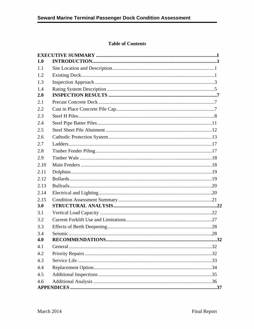
Table of Contents EXECUTIVE SUMMARY .................................................................................................I 1.0 INTRODUCTION....................................................................................................1
1.1 Site Location and Description ..................................................................................1
1.2 Existing Dock...........................................................................................................1
1.3 Inspection Approach ................................................................................................3
1.4 Rating System Description ......................................................................................5 2.0 INSPECTION RESULTS .......................................................................................7
2.1 Precast Concrete Deck .............................................................................................7
2.2 Cast in Place Concrete Pile Cap ...............................................................................7
2.3 Steel H Piles .............................................................................................................8
2.4 Steel Pipe Batter Piles ............................................................................................11
2.5 Steel Sheet Pile Abutment .....................................................................................12
2.6 Cathodic Protection System ...................................................................................13
2.7 Ladders ...................................................................................................................17
2.8 Timber Fender Piling .............................................................................................17
2.9 Timber Wale ..........................................................................................................18
2.10 Main Fenders .........................................................................................................18
2.11 Dolphins .................................................................................................................19
2.12 Bollards ..................................................................................................................19
2.13 Bullrails ..................................................................................................................20
2.14 Electrical and Lighting ...........................................................................................20
2.15 Condition Assessment Summary ...........................................................................21 3.0 STRUCTURAL ANALYSIS ...................................................................................22
3.1 Vertical Load Capacity ..........................................................................................22
3.2 Current Forklift Use and Limitations .....................................................................27
3.3 Effects of Berth Deepening ....................................................................................28
3.4 Seismic ...................................................................................................................28 4.0 RECOMMENDATIONS .........................................................................................32
4.1 General ...................................................................................................................32
4.2 Priority Repairs ......................................................................................................32
4.3 Service Life ............................................................................................................33
4.4 Replacement Option ...............................................................................................34
4.5 Additional Inspections ...........................................................................................35
4.6 Additional Analysis ...............................................................................................36 APPENDICES ......................................................................................................................37
Seward Marine Terminal Passenger Dock Condition Assessment
March 2014 Final Report
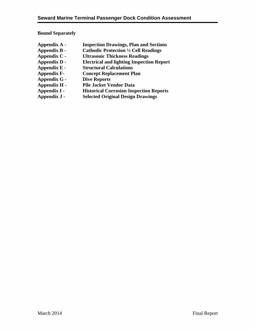
Bound Separately Appendix A - Inspection Drawings, Plan and Sections Appendix B - Cathodic Protection ½ Cell Readings Appendix C - Ultrasonic Thickness Readings Appendix D - Electrical and lighting Inspection Report Appendix E - Structural Calculations Appendix F- Concept Replacement Plan Appendix G - Dive Reports Appendix H - Pile Jacket Vendor Data Appendix I - Historical Corrosion Inspection Reports Appendix J - Selected Original Design Drawings
Seward Marine Terminal Passenger Dock Condition Assessment
Final Report ES-I March 2014
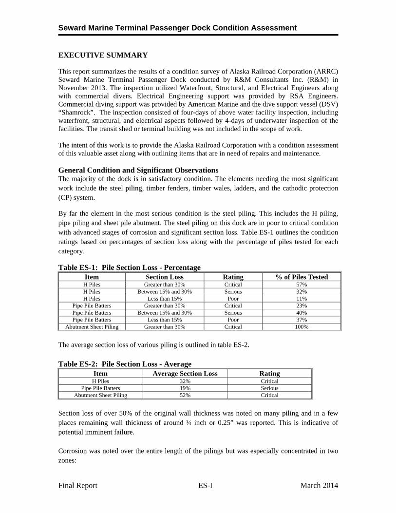
EXECUTIVE SUMMARY
This report summarizes the results of a condition survey of Alaska Railroad Corporation (ARRC) Seward Marine Terminal Passenger Dock conducted by R&M Consultants Inc. (R&M) in November 2013. The inspection utilized Waterfront, Structural, and Electrical Engineers along with commercial divers. Electrical Engineering support was provided by RSA Engineers. Commercial diving support was provided by American Marine and the dive support vessel (DSV) “Shamrock”. The inspection consisted of four-days of above water facility inspection, including waterfront, structural, and electrical aspects followed by 4-days of underwater inspection of the facilities. The transit shed or terminal building was not included in the scope of work. The intent of this work is to provide the Alaska Railroad Corporation with a condition assessment of this valuable asset along with outlining items that are in need of repairs and maintenance. General Condition and Significant Observations The majority of the dock is in satisfactory condition. The elements needing the most significant work include the steel piling, timber fenders, timber wales, ladders, and the cathodic protection (CP) system.
By far the element in the most serious condition is the steel piling. This includes the H piling, pipe piling and sheet pile abutment. The steel piling on this dock are in poor to critical condition with advanced stages of corrosion and significant section loss. Table ES-1 outlines the condition ratings based on percentages of section loss along with the percentage of piles tested for each category.
Table ES-1: Pile Section Loss - Percentage Item Section Loss Rating % of Piles Tested H Piles Greater than 30% Critical 57% H Piles Between 15% and 30% Serious 32% H Piles Less than 15% Poor 11%
Pipe Pile Batters Greater than 30% Critical 23% Pipe Pile Batters Between 15% and 30% Serious 40% Pipe Pile Batters Less than 15% Poor 37%
Abutment Sheet Piling Greater than 30% Critical 100%
The average section loss of various piling is outlined in table ES-2.
Table ES-2: Pile Section Loss - Average Item Average Section Loss Rating H Piles 32% Critical
Pipe Pile Batters 19% Serious Abutment Sheet Piling 52% Critical
Section loss of over 50% of the original wall thickness was noted on many piling and in a few places remaining wall thickness of around ¼ inch or 0.25” was reported. This is indicative of potential imminent failure. Corrosion was noted over the entire length of the pilings but was especially concentrated in two zones:
Seward Marine Terminal Passenger Dock Condition Assessment
Final Report ES-II March 2014
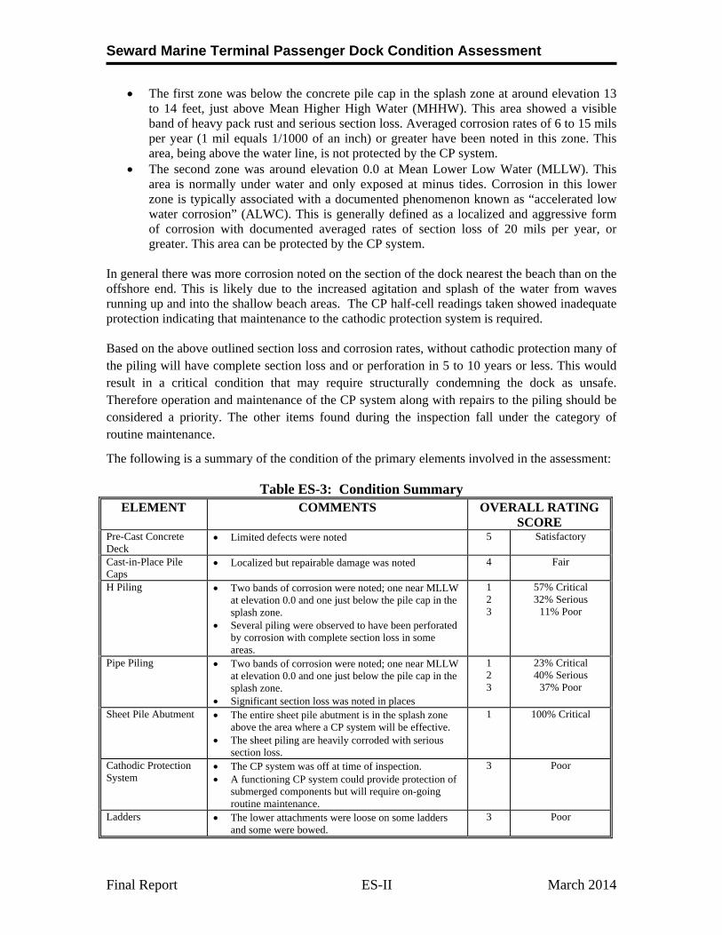
The first zone was below the concrete pile cap in the splash zone at around elevation 13 to 14 feet, just above Mean Higher High Water (MHHW). This area showed a visible band of heavy pack rust and serious section loss. Averaged corrosion rates of 6 to 15 mils per year (1 mil equals 1/1000 of an inch) or greater have been noted in this zone. This area, being above the water line, is not protected by the CP system.
The second zone was around elevation 0.0 at Mean Lower Low Water (MLLW). This area is normally under water and only exposed at minus tides. Corrosion in this lower zone is typically associated with a documented phenomenon known as “accelerated low water corrosion” (ALWC). This is generally defined as a localized and aggressive form of corrosion with documented averaged rates of section loss of 20 mils per year, or greater. This area can be protected by the CP system.
In general there was more corrosion noted on the section of the dock nearest the beach than on the offshore end. This is likely due to the increased agitation and splash of the water from waves running up and into the shallow beach areas. The CP half-cell readings taken showed inadequate protection indicating that maintenance to the cathodic protection system is required. Based on the above outlined section loss and corrosion rates, without cathodic protection many of the piling will have complete section loss and or perforation in 5 to 10 years or less. This would result in a critical condition that may require structurally condemning the dock as unsafe. Therefore operation and maintenance of the CP system along with repairs to the piling should be considered a priority. The other items found during the inspection fall under the category of routine maintenance.
The following is a summary of the condition of the primary elements involved in the assessment:
Table ES-3: Condition Summary ELEMENT COMMENTS OVERALL RATING
SCORE Pre-Cast Concrete Deck
Limited defects were noted 5
Satisfactory
Cast-in-Place Pile Caps
Localized but repairable damage was noted 4 Fair
H Piling Two bands of corrosion were noted; one near MLLW at elevation 0.0 and one just below the pile cap in the splash zone.
Several piling were observed to have been perforated by corrosion with complete section loss in some areas.
1 2 3
57% Critical 32% Serious
11% Poor
Pipe Piling Two bands of corrosion were noted; one near MLLW at elevation 0.0 and one just below the pile cap in the splash zone.
Significant section loss was noted in places
1 2 3
23% Critical 40% Serious
37% Poor
Sheet Pile Abutment The entire sheet pile abutment is in the splash zone above the area where a CP system will be effective.
The sheet piling are heavily corroded with serious section loss.
1 100% Critical
Cathodic Protection System
The CP system was off at time of inspection. A functioning CP system could provide protection of
submerged components but will require on-going routine maintenance.
3 Poor
Ladders The lower attachments were loose on some ladders and some were bowed.
3 Poor
Seward Marine Terminal Passenger Dock Condition Assessment
Final Report ES-III March 2014
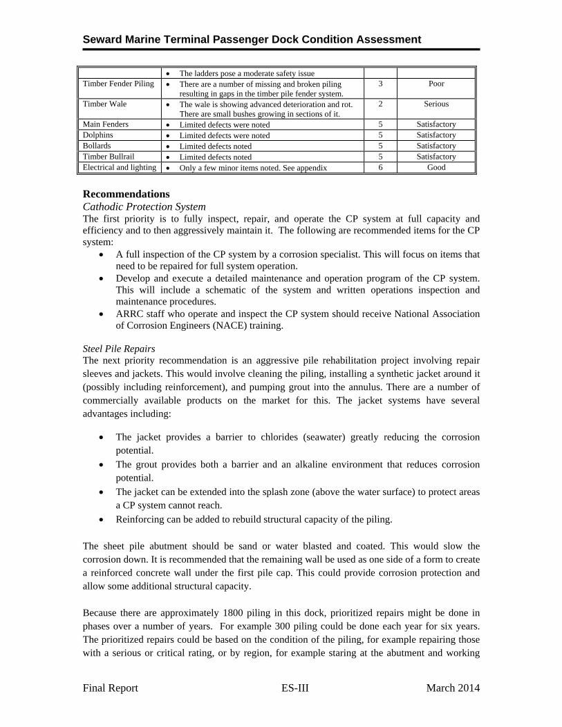
The ladders pose a moderate safety issue Timber Fender Piling There are a number of missing and broken piling
resulting in gaps in the timber pile fender system. 3 Poor
Timber Wale The wale is showing advanced deterioration and rot.
There are small bushes growing in sections of it. 2
Serious
Main Fenders Limited defects were noted 5 Satisfactory Dolphins Limited defects were noted 5 Satisfactory Bollards Limited defects noted 5 Satisfactory Timber Bullrail Limited defects noted 5 Satisfactory Electrical and lighting Only a few minor items noted. See appendix 6 Good
Recommendations Cathodic Protection System The first priority is to fully inspect, repair, and operate the CP system at full capacity and efficiency and to then aggressively maintain it. The following are recommended items for the CP system:
A full inspection of the CP system by a corrosion specialist. This will focus on items that need to be repaired for full system operation.
Develop and execute a detailed maintenance and operation program of the CP system. This will include a schematic of the system and written operations inspection and maintenance procedures.
ARRC staff who operate and inspect the CP system should receive National Association of Corrosion Engineers (NACE) training.
Steel Pile Repairs The next priority recommendation is an aggressive pile rehabilitation project involving repair sleeves and jackets. This would involve cleaning the piling, installing a synthetic jacket around it (possibly including reinforcement), and pumping grout into the annulus. There are a number of commercially available products on the market for this. The jacket systems have several advantages including:
The jacket provides a barrier to chlorides (seawater) greatly reducing the corrosion potential.
The grout provides both a barrier and an alkaline environment that reduces corrosion potential.
The jacket can be extended into the splash zone (above the water surface) to protect areas a CP system cannot reach.
Reinforcing can be added to rebuild structural capacity of the piling. The sheet pile abutment should be sand or water blasted and coated. This would slow the corrosion down. It is recommended that the remaining wall be used as one side of a form to create a reinforced concrete wall under the first pile cap. This could provide corrosion protection and allow some additional structural capacity. Because there are approximately 1800 piling in this dock, prioritized repairs might be done in phases over a number of years. For example 300 piling could be done each year for six years. The prioritized repairs could be based on the condition of the piling, for example repairing those with a serious or critical rating, or by region, for example staring at the abutment and working
Seward Marine Terminal Passenger Dock Condition Assessment
Final Report ES-IV March 2014
outward. Repairing all the piling in the dock would be a costly and involved process. This needs to be weighed against the ARRC’s long term plans and the possibility of future dock replacement.
Timber Fenders Broken and missing fender piling should be replaced. This includes about 35 timber piling.
Wales and Chocks The entire wale and chock system should be replaced. The wale is a continuous horizontal timber along the edge of the dock. The timber fenders are attached to this. Chocks are the short sections of horizontal timbers between the piling. There about 1650 lineal feet of wale to be replaced.
Ladders The ladders should be replaced with fabricated galvanized steel units. At a minimum, this should include 4 ladders on each side and 2 on the end.
Structural Capacity
The current capacity of the dock is adequate for HS 20-44 loading, for the original design forklift loads, and for 600 pounds per square foot (PSF) uniform distributed loads. These loads are in line with the current primary use of the dock which is centered on passenger services for cruise ships and light commercial use. Trains and gantry cranes should not be used without first conducting major repairs to the dock. North Star Stevedores operates two types of large forklifts on the dock: a Taylor model TY-602L with 62,000 lb cargo capacity and a Hyster H970E with 95,000 lb cargo capacity. The calculated capacity of the dock is adequate for the Taylor unit. The Hyster unit must be limited to cargo loads less than or equal to 62,000 lbs. While structural analysis demonstrates that, even with significant section loss due to corrosion, there is still vertical load capacity, any steel piling with 30 percent or greater section lose is at risk of failure due to eccentric loads that could result in combined bending and axial forces. The dock does not meet current design standards for seismic performance. The original design was based on a lateral load of 10% of gravity. Modern design methods are much more complex and include loads of over 100% of gravity, or over 10 times the original design. These modern standards are likely to provide a more accurate representation and analysis of the actual forces and behaviors in an earthquake. The maximum considered earthquake (MCE) also known as the design earthquake is a relatively rare event with an approximate 2500 year return period and a 2% chance of occurrence in 50 years. Although the statistical chances of this occurring are fairly small, it is likely that the dock will fail in the design event. It is also likely that even after comprehensive pile repair the dock will not withstand either MCE or a significant seismic event. The three primary modes of seismic failure include: shearing of the batter piles near the deck connection, the batter piling pulling out of the soils due to large lateral loads, and loss of soil strength due to liquefaction. All three of these are possible and are likely in a large seismic event. Additional Inspections We recommend the following additional inspections:
1. A complete and detailed inspection of the CP system by a NACE trained technician.
Seward Marine Terminal Passenger Dock Condition Assessment
Final Report ES-V March 2014
2. Routine inspections that are completed at regular intervals not to exceed 1 or 2 years. 3. Repair design and construction inspections prior to each phase of rehabilitation work.
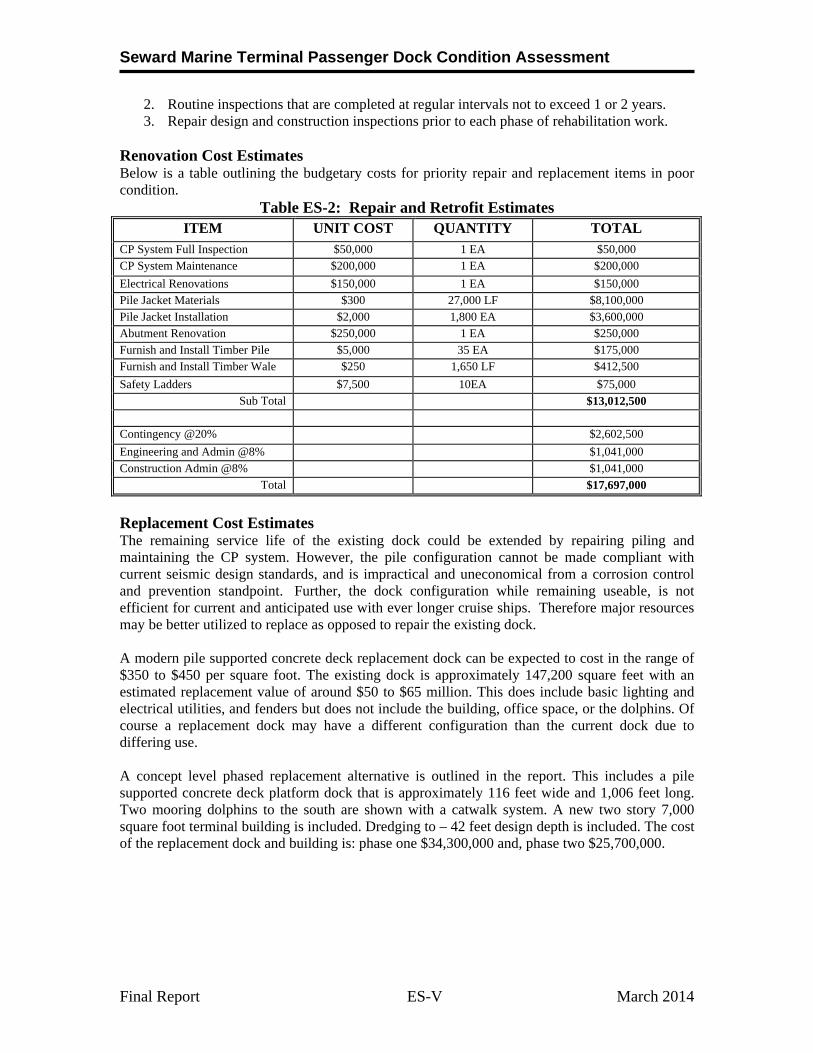
Renovation Cost Estimates Below is a table outlining the budgetary costs for priority repair and replacement items in poor condition.
Table ES-2: Repair and Retrofit Estimates ITEM UNIT COST QUANTITY TOTAL
CP System Full Inspection $50,000 1 EA $50,000 CP System Maintenance $200,000 1 EA $200,000
Electrical Renovations $150,000 1 EA $150,000 Pile Jacket Materials $300 27,000 LF $8,100,000
Pile Jacket Installation $2,000 1,800 EA $3,600,000 Abutment Renovation $250,000 1 EA $250,000
Furnish and Install Timber Pile $5,000 35 EA $175,000 Furnish and Install Timber Wale $250 1,650 LF $412,500
Safety Ladders $7,500 10EA $75,000 Sub Total $13,012,500
Contingency @20% $2,602,500
Engineering and Admin @8% $1,041,000
Construction Admin @8% $1,041,000 Total $17,697,000
Replacement Cost Estimates The remaining service life of the existing dock could be extended by repairing piling and maintaining the CP system. However, the pile configuration cannot be made compliant with current seismic design standards, and is impractical and uneconomical from a corrosion control and prevention standpoint. Further, the dock configuration while remaining useable, is not efficient for current and anticipated use with ever longer cruise ships. Therefore major resources may be better utilized to replace as opposed to repair the existing dock. A modern pile supported concrete deck replacement dock can be expected to cost in the range of $350 to $450 per square foot. The existing dock is approximately 147,200 square feet with an estimated replacement value of around $50 to $65 million. This does include basic lighting and electrical utilities, and fenders but does not include the building, office space, or the dolphins. Of course a replacement dock may have a different configuration than the current dock due to differing use. A concept level phased replacement alternative is outlined in the report. This includes a pile supported concrete deck platform dock that is approximately 116 feet wide and 1,006 feet long. Two mooring dolphins to the south are shown with a catwalk system. A new two story 7,000 square foot terminal building is included. Dredging to – 42 feet design depth is included. The cost of the replacement dock and building is: phase one $34,300,000 and, phase two $25,700,000.
Seward Marine Terminal Passenger Dock Condition Assessment
1.0 INTRODUCTION
The purpose of this report is to summarize the results of the inspection and condition assessment of the Alaska Railroad Corporation (ARRC) Seward Passenger Dock facility. The scope of work included:
An above water inspection of the dock including the top portion of approximately 400 piles, the pile caps, deck, and fenders.
An underwater inspection of approximately 400 piling
An inspection of the electrical service on the dock.
A simplified structural analysis of the piling to include the effects of the reduced pile wall thickness.
A condition assessment. The inspection consisted of four-days of above water inspection of the facilities, including waterfront, structural, and electrical aspects followed by 4-days of underwater inspection of the facilities. The above water inspection included engineers in a skiff under the dock observing the piling at several stages of the tide. Recommendations and budgetary cost estimates are also provided.
1.1 Site Location and Description
The City of Seward is located on Resurrection Bay on the east coast of the Kenai Peninsula about 125 highway miles south of Anchorage. The Passenger Rail Dock is located at about 60º- 7,143’ N, 149º- 25.681’ W.
1.1.1 Climate
According to the Alaska Department of Commerce Community Database online, winter temperatures average about 17 to 30º F and summers range from 49 to 63º F. Average annual precipitation is about 66-inches of rain and 80 inches of snowfall.
1.1.2 Tides
NOAA publishes the following tidal statistics for Seward: Highest observed water 15.69 feet MHHW 10.62 feet MHW 9.71 feet MTL 5.54 feet MSL 5.55 feet MLW 1.38 feet MLLW 0.0 feet Lowest observed water -5.00 feet
1.2 Existing Dock
The Passenger Dock (also known and the Seward Rail Dock and West Dock) is 736 feet long and 200 feet wide and is located at the end of Resurrection Bay near the town of Seward, Alaska There is a 100-foot by 260-foot building located on the north edge of the dock. The facility was designed and constructed by the US Army Corps of Engineers in the mid-1960s following the 1964 Great Alaska Earthquake. Originally it was used for intermodal cargo and had a rail extension on the dock along with a transit or cargo building. Currently, the dock is primarily used for cruise ships and passenger service. Today the rail
Seward Marine Terminal Passenger Dock Condition Assessment
extensions on the dock are not used and the transit building has been converted to provide passenger service and office space. Drawings in the appendix generally illustrate the dock configuration.
The original design depth of the dock was -35 feet MLLW. Recently the berth has been deepened by dredging to -42 feet MLLW. The deeper section begins just outside the fender face and does not extend under the dock to the support piling. The dock is supported by un-coated and un-galvanized vertical steel H-piling. There are over 1800 piles supporting the dock. Depending on location, these are either 14-BP-102 or 14-BP-89 piles. (The original thickness for a 14-BP-102 H pile is 0.704” for both the flange and web. The original thickness for a 14-BP-89 H pile is 0.616” for both the flange and web.) The 14-BP-102 piling are typically located in the outer 8 rows of piling along both the east and west faces of the dock. This section was originally designed to support trains. The 14-BP-89 pilings are typically located in the center section of the dock. Lateral loads are resisted by 16 inch diameter by 3/8 inch or 0.375” wall thickness batter pipe piling. There are two rows of batter piling along the interior of the dock. There are a total of 63 pile bents in the dock. Bents are typically 12 feet on center with the exception of several bents near the expansion joint. This joint is between Bents 32 and 33. The pile bent spacing from Bents 31 to 34 is non-standard. Bent 1 is the abutment and includes a sheetpile retaining wall. This was constructed of Z-27 sheets with an original wall thickness of 3/8 inch or 0.375’. There are vertical H-piling on Bent 1 as well as a row of batter pipe piling.
The deck consists of pre-cast concrete panels supported by cast in-place concrete pile caps. The elevation of the deck is approximately +24 feet. On the outside east and west edges of the dock for the first 8 rows of piling the deck includes railroad ballast (crushed rock) on top of the concrete panels to support railroad tracks. This ballast area is currently overlaid with asphalt. The center section of the deck does not include ballast. This area has an asphalt overlay directly on top of the concrete deck panels. There is a slot in the dock on the west side to accommodate a conveyor system to handle baggage for cruise ships. This is a section where the deck has been removed so that the conveyor can be lowered to reach the cargo door in the side of the vessel. There are seven main fenders located along the east face of the dock and eight on the west face. These were installed sometime after the original construction and consist of “pin pile” units. Each pin pile unit consists of a prefabricated framework supported by two galvanized pipe piling driven into the bottom. The framework includes timber facing and pipe sleeves that slip over the pin piling. The fenders are attached to the deck of the dock with side loading cylindrical rubber energy units. There are also timber fender piling in place along the edge of the dock. These are attached to a timber wale system near deck level. According to previous reports, significant corrosion was noted in a 1978 inspection and an impressed current cathodic protection system was installed in 1979. The ARRC has made considerable efforts to provide and maintain cathodic protection to the dock. Various repairs and upgrades to the system have been completed over the years. Currently there are several generations of impressed current anodes on the dock including at least 3 different types of anodes. These are fed by banks of rectifiers. One bank is located at the south end of the transit shed. Another bank is located near the south edge of the dock near the longitudinal centerline. There are also sacrificial anodes located along the first few bents of piling near the beach. Previous reports outlined significant corrosion on the piling with the maximum deterioration centered around elevation +1 to -1 feet MLLW. Corrosion was also noted up to and including the splash zone above elevation +12 feet MLLW. Remaining pile wall thickness in some of these areas was reported to be less than half the original wall thickness. Significant corrosion was also noted in some of the pile splice
Seward Marine Terminal Passenger Dock Condition Assessment
butt welds. Repairs were made to the piling in some areas. These include bolted pile splice plates. There are at least three distinct types of pile splice plates currently in place. These include types that are bolted into the web and types that are bolted to the flanges.
1.3 Inspection Approach
Members of the condition assessment team, including engineers specializing in the waterfront, structural, and electrical engineering as well as commercial divers traveled to Seward in November 2013 for an on-site inspection of existing facilities.
Modern inspection standards point to a three level inspection approach designed to cover the entire structure with a visual inspection and a statistically representative sampling of certain elements for a closer inspection. R&M generally performed the above and below water inspections using this three level approach. However, due to the large number of piling (over 1800) and to limit project cost, the level 1 visual inspection was limited to approximately 400 piling or about 20 percent of the total number of piles. This provided a representative sampling of the piling. The 3 level inspection protocol is described below:
Level I A complete visual inspection of all exposed components of the element. This typically includes visually inspecting each identified pile from the mudline to the pile cap. Marine growth is not typically removed in the Level 1 inspection. The underwater Level I inspection operation was videotaped and includes a taped dialog between the diver and the topside personnel describing the location, marine growth, and general condition of the structure. The above water Level I inspection included a low tide inspection under the dock in a skiff.
Level II Partial marine growth removal and close up visual and photographic inspection of selected portions of approximately 10 percent of the structure. This was done in a manner designed to produce a statistically representative sample of the underwater components. Close-up photographs were taken of these areas.
Level III Non-destructive testing (NDT) of selected portions of approximately 5 percent of the structures. This was done in a manner designed to produce a statistically representative sample. Ultrasonic thickness readings were taken to determine the remaining wall thickness of the piles. Cathodic protection (CP) half-cell readings, using a silver/silver chloride electrode (half-cell), were also taken to determine the amount of cathodic protection current at the piling.
1.3.1 Cathodic Protection Inspection
The National Association of Corrosion Engineers (NACE) publishes standards and criteria for cathodic protection. One widely used criteria for adequate CP is to maintain the structure at -0.850 volts or more negative with respect to a copper copper sulfate reference cell. Copper copper sulfate reference cells are not intended for use in seawater so it is typical to use a silver silver chloride reference cell. There is a correction factor that can be applied to correlate readings taken with a silver silver chloride cell to standards based on a copper copper sulfate cell. The correction factors vary depending on temperature, salinity, resistivity of the medium, and other factors. For the purposes of this inspection an approximate correction factor of 0.050 volts was applied so that a silver silver chloride CP readings of approximately -0.800 or more negative indicates adequate cathodic protection.
1.3.2 Ultrasonic Thickness Readings
The inspection included NDT ultrasonic thickness readings at various places throughout the facilities to monitor the remaining wall thickness of piling and other structures. A specialized underwater thickness meter was brought to the site and utilized for this purpose. An underwater ultrasonic thickness meter was
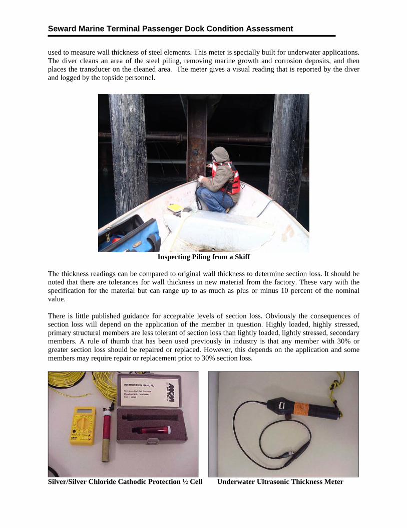
Seward Marine Terminal Passenger Dock Condition Assessment
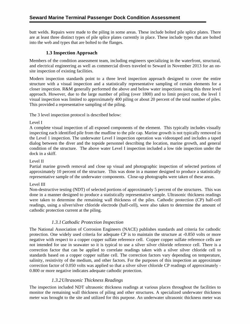
used to measure wall thickness of steel elements. This meter is specially built for underwater applications. The diver cleans an area of the steel piling, removing marine growth and corrosion deposits, and then places the transducer on the cleaned area. The meter gives a visual reading that is reported by the diver and logged by the topside personnel.
Inspecting Piling from a Skiff
The thickness readings can be compared to original wall thickness to determine section loss. It should be noted that there are tolerances for wall thickness in new material from the factory. These vary with the specification for the material but can range up to as much as plus or minus 10 percent of the nominal value. There is little published guidance for acceptable levels of section loss. Obviously the consequences of section loss will depend on the application of the member in question. Highly loaded, highly stressed, primary structural members are less tolerant of section loss than lightly loaded, lightly stressed, secondary members. A rule of thumb that has been used previously in industry is that any member with 30% or greater section loss should be repaired or replaced. However, this depends on the application and some members may require repair or replacement prior to 30% section loss.
Silver/Silver Chloride Cathodic Protection ½ Cell Underwater Ultrasonic Thickness Meter
Seward Marine Terminal Passenger Dock Condition Assessment
1.3.3 Diving Inspection Procedures
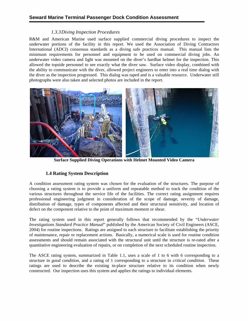
R&M and American Marine used surface supplied commercial diving procedures to inspect the underwater portions of the facility in this report. We used the Association of Diving Contractors International (ADCI) consensus standards as a diving safe practices manual. This manual lists the minimum requirements for personnel and equipment to be used on commercial diving jobs. An underwater video camera and light was mounted on the diver’s hardhat helmet for the inspection. This allowed the topside personnel to see exactly what the diver saw. Surface video display, combined with the ability to communicate with the diver, allowed project engineers to enter into a real time dialog with the diver as the inspection progressed. This dialog was taped and is a valuable resource. Underwater still photographs were also taken and selected photos are included in the report.
Surface Supplied Diving Operations with Helmet Mounted Video Camera
1.4 Rating System Description
A condition assessment rating system was chosen for the evaluation of the structures. The purpose of choosing a rating system is to provide a uniform and repeatable method to track the condition of the various structures throughout the service life of the facilities. The correct rating assignment requires professional engineering judgment in consideration of the scope of damage, severity of damage, distribution of damage, types of components affected and their structural sensitivity, and location of defect on the component relative to the point of maximum moment or shear. The rating system used in this report generally follows that recommended by the “Underwater Investigations Standard Practice Manual” published by the American Society of Civil Engineers (ASCE, 2004) for routine inspections. Ratings are assigned to each structure to facilitate establishing the priority of maintenance, repair or replacement actions. Basically, a numerical scale is used for routine condition assessments and should remain associated with the structural unit until the structure is re-rated after a quantitative engineering evaluation of repairs, or on completion of the next scheduled routine inspection. The ASCE rating system, summarized in Table 1.1, uses a scale of 1 to 6 with 6 corresponding to a structure in good condition, and a rating of 1 corresponding to a structure in critical condition. These ratings are used to describe the existing in-place structure relative to its condition when newly constructed. Our inspection uses this system and applies the ratings to individual elements.
Seward Marine Terminal Passenger Dock Condition Assessment
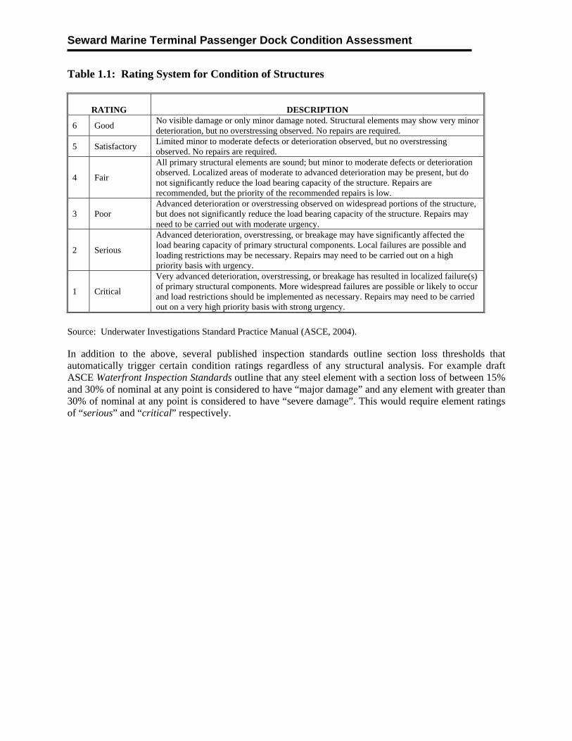
Table 1.1: Rating System for Condition of Structures
RATING DESCRIPTION
6 Good No visible damage or only minor damage noted. Structural elements may show very minor deterioration, but no overstressing observed. No repairs are required.
5 Satisfactory Limited minor to moderate defects or deterioration observed, but no overstressing observed. No repairs are required.
4 Fair
All primary structural elements are sound; but minor to moderate defects or deterioration observed. Localized areas of moderate to advanced deterioration may be present, but do not significantly reduce the load bearing capacity of the structure. Repairs are recommended, but the priority of the recommended repairs is low.
3 Poor Advanced deterioration or overstressing observed on widespread portions of the structure, but does not significantly reduce the load bearing capacity of the structure. Repairs may need to be carried out with moderate urgency.
2 Serious
Advanced deterioration, overstressing, or breakage may have significantly affected the load bearing capacity of primary structural components. Local failures are possible and loading restrictions may be necessary. Repairs may need to be carried out on a high priority basis with urgency.
1 Critical
Very advanced deterioration, overstressing, or breakage has resulted in localized failure(s) of primary structural components. More widespread failures are possible or likely to occur and load restrictions should be implemented as necessary. Repairs may need to be carried out on a very high priority basis with strong urgency.
Source: Underwater Investigations Standard Practice Manual (ASCE, 2004). In addition to the above, several published inspection standards outline section loss thresholds that automatically trigger certain condition ratings regardless of any structural analysis. For example draft ASCE Waterfront Inspection Standards outline that any steel element with a section loss of between 15% and 30% of nominal at any point is considered to have “major damage” and any element with greater than 30% of nominal at any point is considered to have “severe damage”. This would require element ratings of “serious” and “critical” respectively.

Seward Marine Terminal Passenger Dock Condition Assessment
2.0 INSPECTION RESULTS
This section summarizes the inspection results of each primary element of the Passenger Dock facility
2.1 Precast Concrete Deck
The precast concrete deck was found to be in satisfactory condition with little damage.
Deck with Asphalt Overlay Bottom of Precast Deck Panels
Slot in Deck for Baggage Handling Expansion Joint
2.2 Cast in Place Concrete Pile Cap
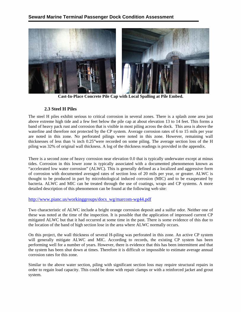
The cast in place pile cap is in fair condition with a few areas of spalling near some of the pile to cap connections. These areas are repairable. Repair would include:
Saw cutting the concrete around the damage to expose clean surfaces of sound concrete, Sand blasting exposed corroded reinforcing steel Installing a form, and Applying polymer modified repair compound.
Seward Marine Terminal Passenger Dock Condition Assessment
Cast-In-Place Concrete Pile Cap with Local Spalling at Pile Embed.
2.3 Steel H Piles
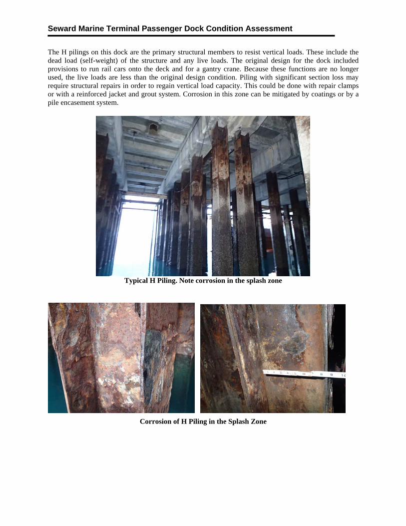
The steel H piles exhibit serious to critical corrosion in several zones. There is a splash zone area just above extreme high tide and a few feet below the pile cap at about elevation 13 to 14 feet. This forms a band of heavy pack rust and corrosion that is visible in most piling across the dock. This area is above the waterline and therefore not protected by the CP system. Average corrosion rates of 6 to 15 mils per year are noted in this zone. No perforated pilings were noted in this zone. However, remaining wall thicknesses of less than ¼ inch 0.25”were recorded on some piling. The average section loss of the H piling was 32% of original wall thickness. A log of the thickness readings is provided in the appendix.
There is a second zone of heavy corrosion near elevation 0.0 that is typically underwater except at minus tides. Corrosion in this lower zone is typically associated with a documented phenomenon known as “accelerated low water corrosion” (ALWC). This is generally defined as a localized and aggressive form of corrosion with documented averaged rates of section loss of 20 mils per year, or greater. ALWC is thought to be produced in part by microbiological induced corrosion (MIC) and to be exasperated by bacteria. ALWC and MIC can be treated through the use of coatings, wraps and CP systems. A more detailed description of this phenomenon can be found at the following web site: http://www.pianc.us/workinggroups/docs_wg/marcom-wg44.pdf Two characteristic of ALWC include a bright orange corrosion deposit and a sulfur odor. Neither one of these was noted at the time of the inspection. It is possible that the application of impressed current CP mitigated ALWC but that it had occurred at some time in the past. There is some evidence of this due to the location of the band of high section lose in the area where ALWC normally occurs. On this project, the wall thickness of several H-piling was perforated in this zone. An active CP system will generally mitigate ALWC and MIC. According to records, the existing CP system has been performing well for a number of years. However, there is evidence that this has been intermittent and that the system has been shut down at times. Therefore it is difficult or impossible to estimate average annual corrosion rates for this zone. Similar to the above water section, piling with significant section loss may require structural repairs in order to regain load capacity. This could be done with repair clamps or with a reinforced jacket and grout system.
Seward Marine Terminal Passenger Dock Condition Assessment
The H pilings on this dock are the primary structural members to resist vertical loads. These include the dead load (self-weight) of the structure and any live loads. The original design for the dock included provisions to run rail cars onto the deck and for a gantry crane. Because these functions are no longer used, the live loads are less than the original design condition. Piling with significant section loss may require structural repairs in order to regain vertical load capacity. This could be done with repair clamps or with a reinforced jacket and grout system. Corrosion in this zone can be mitigated by coatings or by a pile encasement system.
Typical H Piling. Note corrosion in the splash zone
Corrosion of H Piling in the Splash Zone
Seward Marine Terminal Passenger Dock Condition Assessment
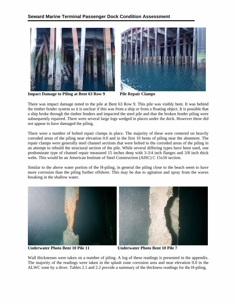
Impact Damage to Piling at Bent 63 Row 9 Pile Repair Clamps There was impact damage noted to the pile at Bent 63 Row 9. This pile was visibly bent. It was behind the timber fender system so it is unclear if this was from a ship or from a floating object. It is possible that a ship broke through the timber fenders and impacted the steel pile and that the broken fender piling were subsequently repaired. There were several large logs wedged in places under the dock. However these did not appear to have damaged the piling. There were a number of bolted repair clamps in place. The majority of these were centered on heavily corroded areas of the piling near elevation 0.0 and in the first 10 bents of piling near the abutment. The repair clamps were generally steel channel sections that were bolted to the corroded areas of the piling in an attempt to rebuild the structural section of the pile. While several differing types have been used, one predominate type of channel repair measured 15 inches deep with 3-3/4 inch flanges and 3/8 inch thick webs. This would be an American Institute of Steel Construction (AISC) C 15x50 section. Similar to the above water portion of the H-piling, in general the piling close to the beach seem to have more corrosion than the piling further offshore. This may be due to agitation and spray from the waves breaking in the shallow water.
Underwater Photo Bent 10 Pile 11 Underwater Photo Bent 10 Pile 7 Wall thicknesses were taken on a number of piling. A log of these readings is presented in the appendix. The majority of the readings were taken in the splash zone corrosion area and near elevation 0.0 in the ALWC zone by a diver. Tables 2.1 and 2.2 provide a summary of the thickness readings for the H-piling.
Seward Marine Terminal Passenger Dock Condition Assessment
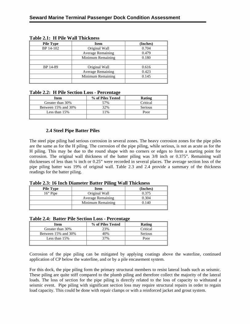
Table 2.1: H Pile Wall Thickness
Pile Type Item (Inches) BP 14-102 Original Wall 0.704
Average Remaining 0.479 Minimum Remaining 0.180
BP 14-89 Original Wall 0.616
Average Remaining 0.423 Minimum Remaining 0.145
Table 2.2: H Pile Section Loss - Percentage
Item % of Piles Tested Rating Greater than 30% 57% Critical
Between 15% and 30% 32% Serious Less than 15% 11% Poor
2.4 Steel Pipe Batter Piles
The steel pipe piling had serious corrosion in several zones. The heavy corrosion zones for the pipe piles are the same as for the H piling. The corrosion of the pipe piling, while serious, is not as acute as for the H piling. This may be due to the round shape with no corners or edges to form a starting point for corrosion. The original wall thickness of the batter piling was 3/8 inch or 0.375”. Remaining wall thicknesses of less than ¼ inch or 0.25” were recorded in several places. The average section loss of the pipe piling batter was 19% of original wall. Table 2.3 and 2.4 provide a summary of the thickness readings for the batter piling. Table 2.3: 16 Inch Diameter Batter Piling Wall Thickness
Pile Type Item (Inches) 16” Pipe Original Wall 0.375
Average Remaining 0.304 Minimum Remaining 0.140
Table 2.4: Batter Pile Section Loss - Percentage
Item % of Piles Tested Rating Greater than 30% 23% Critical
Between 15% and 30% 40% Serious Less than 15% 37% Poor
Corrosion of the pipe piling can be mitigated by applying coatings above the waterline, continued application of CP below the waterline, and or by a pile encasement system. For this dock, the pipe piling form the primary structural members to resist lateral loads such as seismic. These piling are quite stiff compared to the plumb piling and therefore collect the majority of the lateral loads. The loss of section for the pipe piling is directly related to the loss of capacity to withstand a seismic event. Pipe piling with significant section loss may require structural repairs in order to regain load capacity. This could be done with repair clamps or with a reinforced jacket and grout system.
Seward Marine Terminal Passenger Dock Condition Assessment
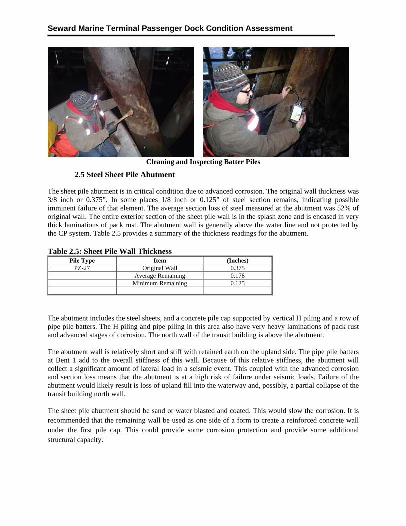
Cleaning and Inspecting Batter Piles
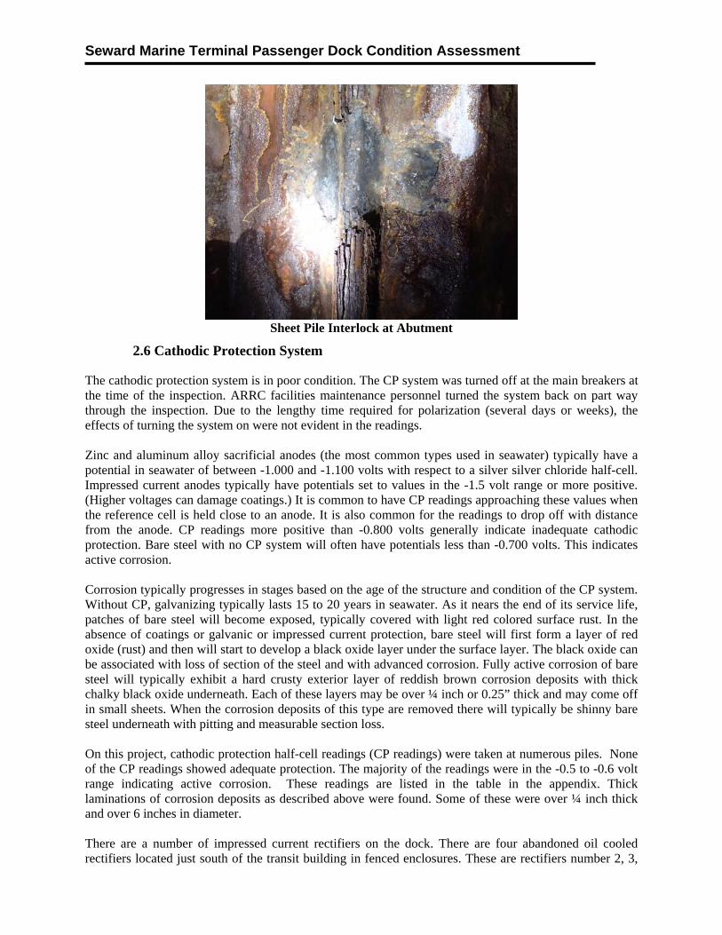
2.5 Steel Sheet Pile Abutment
The sheet pile abutment is in critical condition due to advanced corrosion. The original wall thickness was 3/8 inch or 0.375”. In some places 1/8 inch or 0.125” of steel section remains, indicating possible imminent failure of that element. The average section loss of steel measured at the abutment was 52% of original wall. The entire exterior section of the sheet pile wall is in the splash zone and is encased in very thick laminations of pack rust. The abutment wall is generally above the water line and not protected by the CP system. Table 2.5 provides a summary of the thickness readings for the abutment. Table 2.5: Sheet Pile Wall Thickness
Pile Type Item (Inches) PZ-27 Original Wall 0.375
Average Remaining 0.178 Minimum Remaining 0.125
The abutment includes the steel sheets, and a concrete pile cap supported by vertical H piling and a row of pipe pile batters. The H piling and pipe piling in this area also have very heavy laminations of pack rust and advanced stages of corrosion. The north wall of the transit building is above the abutment. The abutment wall is relatively short and stiff with retained earth on the upland side. The pipe pile batters at Bent 1 add to the overall stiffness of this wall. Because of this relative stiffness, the abutment will collect a significant amount of lateral load in a seismic event. This coupled with the advanced corrosion and section loss means that the abutment is at a high risk of failure under seismic loads. Failure of the abutment would likely result is loss of upland fill into the waterway and, possibly, a partial collapse of the transit building north wall. The sheet pile abutment should be sand or water blasted and coated. This would slow the corrosion. It is recommended that the remaining wall be used as one side of a form to create a reinforced concrete wall under the first pile cap. This could provide some corrosion protection and provide some additional structural capacity.
Seward Marine Terminal Passenger Dock Condition Assessment
Sheet Pile Interlock at Abutment
2.6 Cathodic Protection System
The cathodic protection system is in poor condition. The CP system was turned off at the main breakers at the time of the inspection. ARRC facilities maintenance personnel turned the system back on part way through the inspection. Due to the lengthy time required for polarization (several days or weeks), the effects of turning the system on were not evident in the readings. Zinc and aluminum alloy sacrificial anodes (the most common types used in seawater) typically have a potential in seawater of between -1.000 and -1.100 volts with respect to a silver silver chloride half-cell. Impressed current anodes typically have potentials set to values in the -1.5 volt range or more positive. (Higher voltages can damage coatings.) It is common to have CP readings approaching these values when the reference cell is held close to an anode. It is also common for the readings to drop off with distance from the anode. CP readings more positive than -0.800 volts generally indicate inadequate cathodic protection. Bare steel with no CP system will often have potentials less than -0.700 volts. This indicates active corrosion. Corrosion typically progresses in stages based on the age of the structure and condition of the CP system. Without CP, galvanizing typically lasts 15 to 20 years in seawater. As it nears the end of its service life, patches of bare steel will become exposed, typically covered with light red colored surface rust. In the absence of coatings or galvanic or impressed current protection, bare steel will first form a layer of red oxide (rust) and then will start to develop a black oxide layer under the surface layer. The black oxide can be associated with loss of section of the steel and with advanced corrosion. Fully active corrosion of bare steel will typically exhibit a hard crusty exterior layer of reddish brown corrosion deposits with thick chalky black oxide underneath. Each of these layers may be over ¼ inch or 0.25” thick and may come off in small sheets. When the corrosion deposits of this type are removed there will typically be shinny bare steel underneath with pitting and measurable section loss. On this project, cathodic protection half-cell readings (CP readings) were taken at numerous piles. None of the CP readings showed adequate protection. The majority of the readings were in the -0.5 to -0.6 volt range indicating active corrosion. These readings are listed in the table in the appendix. Thick laminations of corrosion deposits as described above were found. Some of these were over ¼ inch thick and over 6 inches in diameter. There are a number of impressed current rectifiers on the dock. There are four abandoned oil cooled rectifiers located just south of the transit building in fenced enclosures. These are rectifiers number 2, 3,
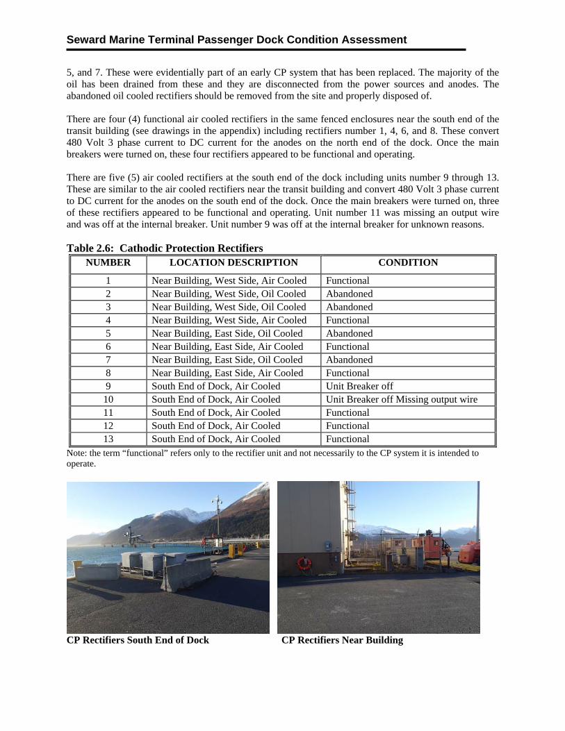
Seward Marine Terminal Passenger Dock Condition Assessment
5, and 7. These were evidentially part of an early CP system that has been replaced. The majority of the oil has been drained from these and they are disconnected from the power sources and anodes. The abandoned oil cooled rectifiers should be removed from the site and properly disposed of. There are four (4) functional air cooled rectifiers in the same fenced enclosures near the south end of the transit building (see drawings in the appendix) including rectifiers number 1, 4, 6, and 8. These convert 480 Volt 3 phase current to DC current for the anodes on the north end of the dock. Once the main breakers were turned on, these four rectifiers appeared to be functional and operating. There are five (5) air cooled rectifiers at the south end of the dock including units number 9 through 13. These are similar to the air cooled rectifiers near the transit building and convert 480 Volt 3 phase current to DC current for the anodes on the south end of the dock. Once the main breakers were turned on, three of these rectifiers appeared to be functional and operating. Unit number 11 was missing an output wire and was off at the internal breaker. Unit number 9 was off at the internal breaker for unknown reasons. Table 2.6: Cathodic Protection Rectifiers
NUMBER LOCATION DESCRIPTION CONDITION
1 Near Building, West Side, Air Cooled Functional 2 Near Building, West Side, Oil Cooled Abandoned 3 Near Building, West Side, Oil Cooled Abandoned 4 Near Building, West Side, Air Cooled Functional 5 Near Building, East Side, Oil Cooled Abandoned 6 Near Building, East Side, Air Cooled Functional 7 Near Building, East Side, Oil Cooled Abandoned 8 Near Building, East Side, Air Cooled Functional 9 South End of Dock, Air Cooled Unit Breaker off 10 South End of Dock, Air Cooled Unit Breaker off Missing output wire 11 South End of Dock, Air Cooled Functional12 South End of Dock, Air Cooled Functional13 South End of Dock, Air Cooled Functional
Note: the term “functional” refers only to the rectifier unit and not necessarily to the CP system it is intended to operate.
CP Rectifiers South End of Dock CP Rectifiers Near Building
Seward Marine Terminal Passenger Dock Condition Assessment
Typical Air Cooled Rectifier Rectifier Name Plate
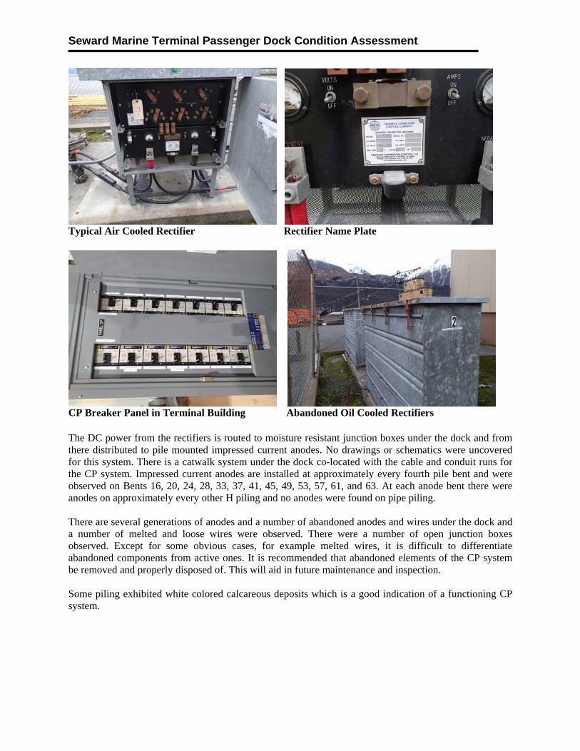
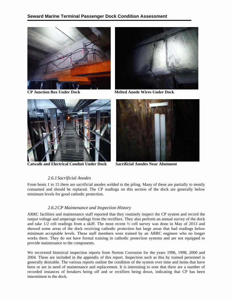
CP Breaker Panel in Terminal Building Abandoned Oil Cooled Rectifiers The DC power from the rectifiers is routed to moisture resistant junction boxes under the dock and from there distributed to pile mounted impressed current anodes. No drawings or schematics were uncovered for this system. There is a catwalk system under the dock co-located with the cable and conduit runs for the CP system. Impressed current anodes are installed at approximately every fourth pile bent and were observed on Bents 16, 20, 24, 28, 33, 37, 41, 45, 49, 53, 57, 61, and 63. At each anode bent there were anodes on approximately every other H piling and no anodes were found on pipe piling. There are several generations of anodes and a number of abandoned anodes and wires under the dock and a number of melted and loose wires were observed. There were a number of open junction boxes observed. Except for some obvious cases, for example melted wires, it is difficult to differentiate abandoned components from active ones. It is recommended that abandoned elements of the CP system be removed and properly disposed of. This will aid in future maintenance and inspection. Some piling exhibited white colored calcareous deposits which is a good indication of a functioning CP system.
Seward Marine Terminal Passenger Dock Condition Assessment
CP Junction Box Under Dock Melted Anode Wires Under Dock
Catwalk and Electrical Conduit Under Dock Sacrificial Anodes Near Abutment
2.6.1 Sacrificial Anodes
From bents 1 to 15 there are sacrificial anodes welded to the piling. Many of these are partially to mostly consumed and should be replaced. The CP readings on this section of the dock are generally below minimum levels for good cathodic protection.
2.6.2 CP Maintenance and Inspection History
ARRC facilities and maintenance staff reported that they routinely inspect the CP system and record the output voltage and amperage readings from the rectifiers. They also perform an annual survey of the dock and take 1/2 cell readings from a skiff. The most recent ½ cell survey was done in May of 2013 and showed some areas of the dock receiving cathodic protection but large areas that had readings below minimum acceptable levels. These staff members were trained by an ARRC engineer who no longer works there. They do not have formal training in cathodic protection systems and are not equipped to provide maintenance to the components. We recovered historical inspection reports from Norton Corrosion for the years 1996, 1998, 2000 and 2004. These are included in the appendix of this report. Inspection such as this by trained personnel is generally desirable. The various reports outline the condition of the system over time and items that have been or are in need of maintenance and replacement. It is interesting to note that there are a number of recorded instances of breakers being off and or rectifiers being down, indicating that CP has been intermittent to the dock.
Seward Marine Terminal Passenger Dock Condition Assessment
Due to the advanced corrosion and section loss observed on the pilings it is recommend that the CP system be completely inspected by trained professionals and that an aggressive maintenance system be implemented. ARRC personnel involved in the maintenance and inspection of the CP system should undergo NACE training.
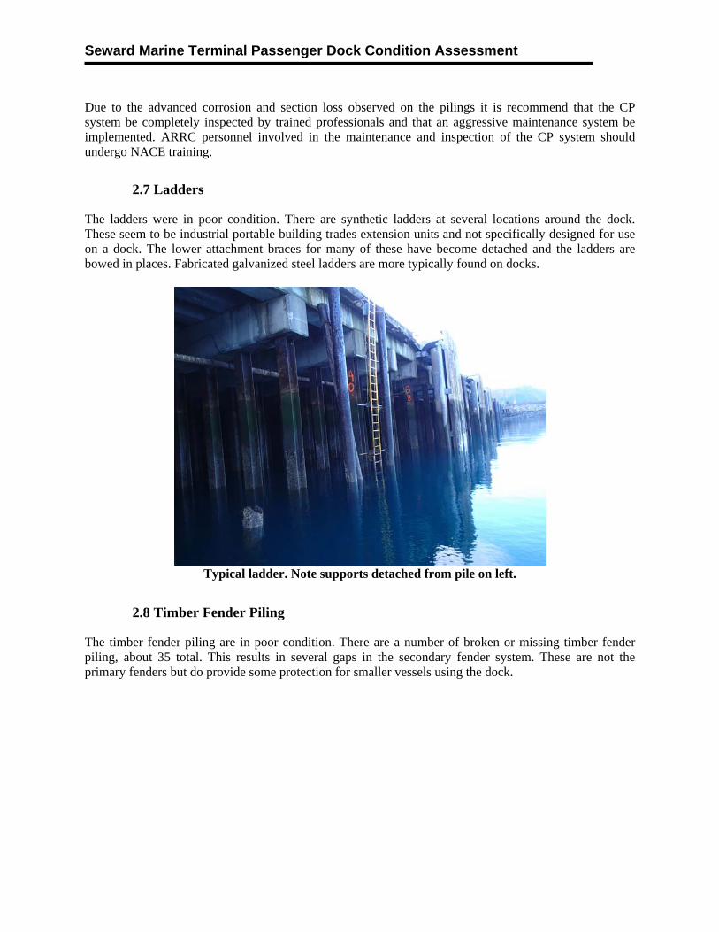
2.7 Ladders
The ladders were in poor condition. There are synthetic ladders at several locations around the dock. These seem to be industrial portable building trades extension units and not specifically designed for use on a dock. The lower attachment braces for many of these have become detached and the ladders are bowed in places. Fabricated galvanized steel ladders are more typically found on docks.
Typical ladder. Note supports detached from pile on left.
2.8 Timber Fender Piling
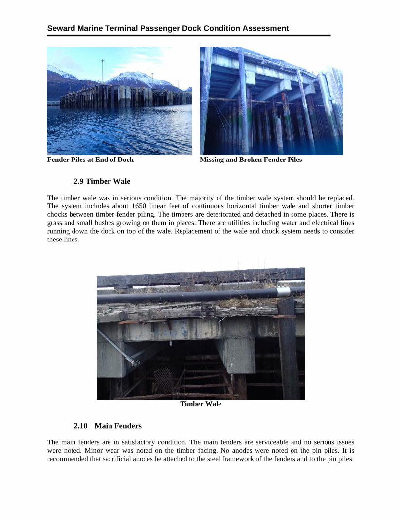
The timber fender piling are in poor condition. There are a number of broken or missing timber fender piling, about 35 total. This results in several gaps in the secondary fender system. These are not the primary fenders but do provide some protection for smaller vessels using the dock.
Seward Marine Terminal Passenger Dock Condition Assessment
Fender Piles at End of Dock Missing and Broken Fender Piles
2.9 Timber Wale
The timber wale was in serious condition. The majority of the timber wale system should be replaced. The system includes about 1650 linear feet of continuous horizontal timber wale and shorter timber chocks between timber fender piling. The timbers are deteriorated and detached in some places. There is grass and small bushes growing on them in places. There are utilities including water and electrical lines running down the dock on top of the wale. Replacement of the wale and chock system needs to consider these lines.
Timber Wale
2.10 Main Fenders
The main fenders are in satisfactory condition. The main fenders are serviceable and no serious issues were noted. Minor wear was noted on the timber facing. No anodes were noted on the pin piles. It is recommended that sacrificial anodes be attached to the steel framework of the fenders and to the pin piles.
Seward Marine Terminal Passenger Dock Condition Assessment
Main Fender at East Side of Dock Main Fender SW Corner of Dock
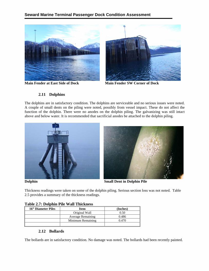
2.11 Dolphins
The dolphins are in satisfactory condition. The dolphins are serviceable and no serious issues were noted. A couple of small dents on the piling were noted, possibly from vessel impact. These do not affect the function of the dolphin. There were no anodes on the dolphin piling. The galvanizing was still intact above and below water. It is recommended that sacrificial anodes be attached to the dolphin piling.
Dolphin Small Dent in Dolphin Pile Thickness readings were taken on some of the dolphin piling. Serious section loss was not noted. Table 2.5 provides a summary of the thickness readings. Table 2.7: Dolphin Pile Wall Thickness
16” Diameter Piles Item (Inches) Original Wall 0.50 Average Remaining 0.486 Minimum Remaining 0.470
2.12 Bollards
The bollards are in satisfactory condition. No damage was noted. The bollards had been recently painted.
Seward Marine Terminal Passenger Dock Condition Assessment
Bollard
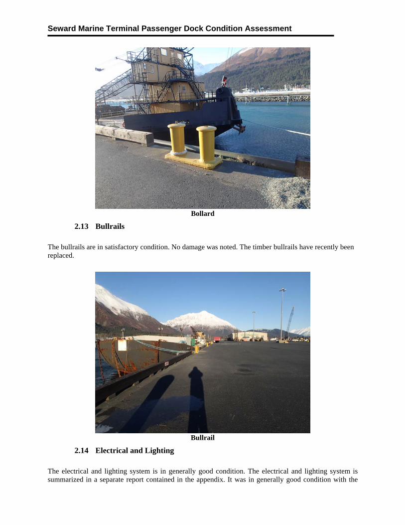
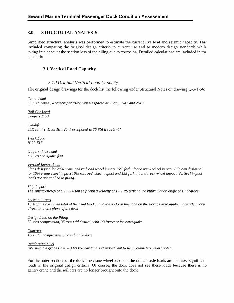
2.13 Bullrails
The bullrails are in satisfactory condition. No damage was noted. The timber bullrails have recently been replaced.
Bullrail
2.14 Electrical and Lighting
The electrical and lighting system is in generally good condition. The electrical and lighting system is summarized in a separate report contained in the appendix. It was in generally good condition with the

Seward Marine Terminal Passenger Dock Condition Assessment
exception of a few items. Several components of the CP system appear to have been abandoned in place and should be removed.
2.15 Condition Assessment Summary
Table 2.8 below provides a summary of the overall condition assessment at each facility, including a rating score for each structure in accordance with the rating system described in Section 1.4. In general, the lowest rating score of 1 = Critical condition and the highest score of 6 = Good condition.
Table 2.8: Condition Summary
ELEMENT COMMENTS OVERALL RATING SCORE
Pre-Cast Concrete Deck Limited defects were noted 5
Satisfactory
Cast-in-Place Pile Caps Localized but repairable damage was noted 4 Fair H Piling Two bands of corrosion were noted; one near MLLW at
elevation 0.0 and one just below the pile cap in the splash zone.
Several piling were observed to have been perforated by corrosion with complete section loss in some areas.
1 2 3
57% Critical 32% Serious
11% Poor
Pipe Piling Two bands of corrosion were noted; one near MLLW at elevation 0.0 and one just below the pile cap in the splash zone.
Significant section loss was noted in places
1 2 3
23% Critical 40% Serious
37% Poor
Sheet Pile Abutment The entire sheet pile abutment is in the splash zone above the area where a CP system will be effective.
The sheet piling are heavily corroded with serious section loss.
1 100% Critical
Cathodic Protection System
The CP system was off at time of inspection. A functioning CP system could provide protection of
submerged components but will require on-going routine maintenance.
3 Poor
Ladders The lower attachments were loose on some ladders and some were bowed.
The ladders pose a moderate safety issue
3 Poor
Timber Fender Piling There are a number of missing and broken piling resulting in gaps in the timber pile fender system.
3 Poor
Timber Wale The wale is showing advanced deterioration and rot. There are small bushes growing in sections of it.
2
Serious
Main Fenders Limited defects were noted 5 Satisfactory Dolphins Limited defects were noted 5 Satisfactory Bollards Limited defects noted 5 Satisfactory Timber Bullrail Limited defects noted 5 Satisfactory Electrical and lighting Only a few minor items noted. See appendix 6 Good
Seward Marine Terminal Passenger Dock Condition Assessment
3.0 STRUCTURAL ANALYSIS
Simplified structural analysis was performed to estimate the current live load and seismic capacity. This included comparing the original design criteria to current use and to modern design standards while taking into account the section loss of the piling due to corrosion. Detailed calculations are included in the appendix.
3.1 Vertical Load Capacity
3.1.1 Original Vertical Load Capacity
The original design drawings for the dock list the following under Structural Notes on drawing Q-5-1-56: Crane Load 50 K ea. wheel, 4 wheels per truck, wheels spaced at 2’-8”, 3’-4” and 2’-8” Rail Car Load Coopers E 50 Forklift 35K ea. tire. Dual 18 x 25 tires inflated to 70 PSI tread 9’-0” Truck Load H-20-S16 Uniform Live Load 600 lbs per square foot Vertical Impact Load Slabs designed for 20% crane and railroad wheel impact 15% fork lift and truck wheel impact. Pile cap designed for 10% crane wheel impact 10% railroad wheel impact and 155 fork lift and truck wheel impact. Vertical impact loads are not applied to piling. Ship Impact The kinetic energy of a 25,000 ton ship with a velocity of 1.0 FPS striking the bullrail at an angle of 10 degrees. Seismic Forces 10% of the combined total of the dead load and ½ the uniform live load on the storage area applied laterally in any direction in the plane of the deck Design Load on the Piling 65 tons compression, 35 tons withdrawal, with 1/3 increase for earthquake. Concrete 4000 PSI compressive Strength at 28 days Reinforcing Steel Intermediate grade Fs = 20,000 PSI bar laps and embedment to be 36 diameters unless noted
For the outer sections of the dock, the crane wheel load and the rail car axle loads are the most significant loads in the original design criteria. Of course, the dock does not see these loads because there is no gantry crane and the rail cars are no longer brought onto the dock.

Seward Marine Terminal Passenger Dock Condition Assessment
The Cooper E Series loading is defined below in Figure 3.1.
Figure 3.1: Cooper E Series Unit Loading
The values shown in Figure 3.1 are in units of 1000 lb axle loads. For E50 loading each unit increment is multiplied by 50. For example the 1.00 axle loads at 5’ on center become 50,000 lb axle loads under Cooper E50 loading. Standard gage is 4’-8.5”, which is the effective width of each axle.
The BP-102 H piling are generally placed under the crane and rail car loading areas and are spaced at 12 feet on center longitudinally down the dock (along with the pile caps and bents) and at 6 feet on center transversely across the dock (in each pile cap or bent).
Moving down a notch in the hierarchy, the next most significant loads from the original design criteria are the fork lift, H20-S16 vehicle, and the 600 PSF distributed live loads. These loads are not confined to the outer sections of the dock and can act at any point including the center section of the dock supported by the slightly smaller BP-89 H piling.
The listed forklift tire loads are for a moderately large sized unit.
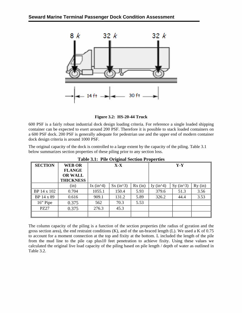
The H20 – S16 designation was replaced by AASHTO in the 1960s with the HS-20 designation. This means a truck with semi-trailer. A modern HS20-44 truck load distribution is shown in Figure 3.2.
Seward Marine Terminal Passenger Dock Condition Assessment
Figure 3.2: HS-20-44 Truck
600 PSF is a fairly robust industrial dock design loading criteria. For reference a single loaded shipping container can be expected to exert around 200 PSF. Therefore it is possible to stack loaded containers on a 600 PSF dock. 200 PSF is generally adequate for pedestrian use and the upper end of modern container dock design criteria is around 1000 PSF.
The original capacity of the dock is controlled to a large extent by the capacity of the piling. Table 3.1 below summarizes section properties of these piling prior to any section loss.
Table 3.1: Pile Original Section Properties SECTION WEB OR
FLANGE OR WALL
THICKNESS
X-X
Y-Y
(in) Ix (in^4) Sx (in^3) Rx (in) Iy (in^4) Sy (in^3) Ry (in) BP 14 x 102 0.704 1055.1 150.4 5.93 379.6 51.3 3.56 BP 14 x 89 0.616 909.1 131.2 5.89 326.2 44.4 3.53
16” Pipe 0.375 562 70.3 5.53 PZ27 0.375 276.3 45.3
The column capacity of the piling is a function of the section properties (the radius of gyration and the gross section area), the end restraint conditions (K), and of the un-braced length (L). We used a K of 0.75 to account for a moment connection at the top and fixity at the bottom. L included the length of the pile from the mud line to the pile cap plus10 feet penetration to achieve fixity. Using these values we calculated the original live load capacity of the piling based on pile length / depth of water as outlined in Table 3.2.
Seward Marine Terminal Passenger Dock Condition Assessment
Table 3.2: H Pile Original Live Load Capacity SECTION WATER DEPTH
(FEET FROM MLLW)LIVE LOAD CAPACITY
(TON)
BP 14 x 102 -35 67.89
BP 14 x 102 -25 104.69
BP 14 x 102 -15 152.83
BP 14 x 102 -5 203.58
BP 14 x 102 +5 250.23
BP 14 x 89 -35 60.89
BP 14 x 89 -25 92.39
BP 14 x 89 -15 134.54
BP 14 x 89 -5 179.04
BP 14 x 89 +5 220.14
Based on the above, the original dock was a robust, highly redundant structure, adequately designed for fairly significant cargo and equipment loads.
3.1.2 Current Vertical Load Capacity
The reduced section of the H piling due to corrosion can effect whether the pile is considered compact, non-compact, or slender. If the pile is compact then the full axial load can be applied without modification. If it is non-compact then localized bulking may occur and a reduced allowable load is used. If the pile is slender it is generally deemed not fit for purpose and a different section or larger pile is suggested. The American Institute of Steel Construction (AISC) publishes design standards that outline means to calculate the capacity of piling for various lengths and conditions including modifiers for non-compact sections. A summary of the compact section analysis is shown in the table below.
Table 3.3: H Pile Compact Section Analysis Section Condition Remaining Wall
Thickness Compact State
BP 102 Original 0.707” Compact BP 102 1/3 section loss 0.470” Compact BP 102 Average section loss 0.479” Compact BP 102 ½ section loss 0.352” Non- Compact BP 102 Max section loss 0.180” Slender
BP 89 Original 0.616” Compact BP 89 1/3 section loss 0.410” Non-Compact BP 89 Average section loss 0.423” Non-Compact BP 89 ½ section loss 0.308” Non Compact BP 89 Max section loss 0.145” Slender
Section loss varied widely in the splash zone. For simplicity we assumed an approximate reduced wall thickness by using 1/3 of the original section loss (2/3 remaining wall thickness) for the H piling. Note that these are the approximate average values found from the inspection results. Using these values we calculated the section properties and remaining live load capacities as outlined in tables 3.4 and 3.5.

Seward Marine Terminal Passenger Dock Condition Assessment
While analysis shows that the pilings still have significant load capacity there are several factors that are of concern. First, section loss estimates are based on a partial inspection. It is possible that more serious corrosion would be uncovered with additional inspections. Second, the remaining live load capacity is based on pure axial loads and is not combined with any bending forces. Actual bending forces are likely due to small eccentricities. These could be caused by non-uniform section loss or eccentric loads. The radius of gyration section property that governs axial capacity is not sensitive to wall thickness. However the moment of inertia and section modulus are quite sensitive to the member wall thickness. These later two section properties govern the bending capacity. This points to a condition where a small eccentricity in the loads or a small lateral load combined with the axial loads could cause a pile with reduced wall thickness to fail.
Table 3.4: H Pile Revised Section Properties for Splash Zone SECTION WEB AND
FLANGE THICKNESS
X-X
Y-Y
(in) Ix (in^4) Sx (in^3) Rx (in) Iy (in^4) Sy (in^3) Ry (in) BP 14 x 102 0.470 727.15 103.64 5.93 253.23 34.257 3.56 BP 14 x 89 0.410 620.54 89.569 5.89 216.96 89.569 3.53
Table 3.5: H Pile 1/3 Section Loss Live Load Capacity SECTION WATER DEPTH
(FEET FROM MLLW)LIVE LOAD CAPACITY
(TON)
BP 14 x 102 -35 38.19
BP 14 x 102 -25 62.84
BP 14 x 102 -15 94.98
BP 14 x 102 -5 128.88
BP 14 x 102 +5 159.98
BP 14 x 89 -35 36.09
BP 14 x 89 -25 57.14
BP 14 x 89 -15 83.09
BP 14 x 89 -5 110.14
BP 14 x 89 +5 134.69
Note that section loss of 30% is generally considered severe damage and triggers a critical condition rating. That said these piling, even in a corroded state, still have significant load capacity. Section loss varied widely in the ALWC zone near elevation 0.0. For simplicity we assumed an approximate reduced wall thickness by using 1/2 of the original section loss for the H piling in this zone. Using these values we calculated the below outlined section properties and remaining live load capacities. Similar to the above for the splash zone, piling with 50% section loss can be considered to have severe damage and a critical condition rating.
Seward Marine Terminal Passenger Dock Condition Assessment
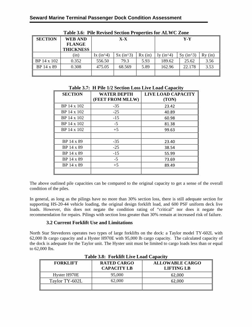
Table 3.6: Pile Revised Section Properties for ALWC Zone SECTION WEB AND
FLANGE THICKNESS
X-X
Y-Y
(in) Ix (in^4) Sx (in^3) Rx (in) Iy (in^4) Sy (in^3) Ry (in) BP 14 x 102 0.352 556.50 79.3 5.93 189.62 25.62 3.56 BP 14 x 89 0.308 475.05 68.569 5.89 162.96 22.178 3.53
Table 3.7: H Pile 1/2 Section Loss Live Load Capacity SECTION WATER DEPTH
(FEET FROM MLLW)LIVE LOAD CAPACITY
(TON)
BP 14 x 102 -35 23.42
BP 14 x 102 -25 40.89
BP 14 x 102 -15 60.98
BP 14 x 102 -5 81.38
BP 14 x 102 +5 99.63
BP 14 x 89 -35 23.40
BP 14 x 89 -25 38.54
BP 14 x 89 -15 55.99
BP 14 x 89 -5 73.69
BP 14 x 89 +5 89.49
The above outlined pile capacities can be compared to the original capacity to get a sense of the overall condition of the piles. In general, as long as the pilings have no more than 30% section loss, there is still adequate section for supporting HS-20-44 vehicle loading, the original design forklift load, and 600 PSF uniform deck live loads. However, this does not negate the condition rating of “critical” nor does it negate the recommendation for repairs. Pilings with section loss greater than 30% remain at increased risk of failure.
3.2 Current Forklift Use and Limitations
North Star Stevedores operates two types of large forklifts on the dock: a Taylor model TY-602L with 62,000 lb cargo capacity and a Hyster H970E with 95,000 lb cargo capacity. The calculated capacity of the dock is adequate for the Taylor unit. The Hyster unit must be limited to cargo loads less than or equal to 62,000 lbs.
Table 3.8: Forklift Live Load Capacity FORKLIFT RATED CARGO
CAPACITY LB ALLOWABLE CARGO
LIFTING LB
Hyster H970E 95,000 62,000
Taylor TY-602L 62,000 62,000
Seward Marine Terminal Passenger Dock Condition Assessment
3.3 Effects of Berth Deepening
As mentioned previously the original design depth of the berth was -35 feet MLLW. Recently the berth has been dredged to -42 feet MLLW. The dredge line is just outside the fender face. While the support pilings are not in the dredge prism, they are adjacent to it and in close proximity. This has the potential to affect the structural capacity of the piling. It is difficult to calculate the exact effect of this without precise data as to the location of the edge of the dredge prism. That said if the piling were placed in -42 feet of water, as opposed to -35 feet of water, there would be an approximate 20% reduction in the pile column capacity with an increase in un-braced length of 7 feet. Also, the piling are only embed about 35 feet. If 7 feet of soil were removed around the piling it would reduce the embed depth by about 20%. This would remove some of the soil support and further reduce the pie capacity. Finally the divers reported a small “cliff” outside the fender face where the dredging produced vertical wall about 7 feet high. It is likely that soils from under the dock will slough into this area and that the slopes will eventually find an equilibrium position with a flatter angle. If a large mass of soil sloughs off at once it could put lateral loads on the piling on the edge of the dock.
3.4 Seismic
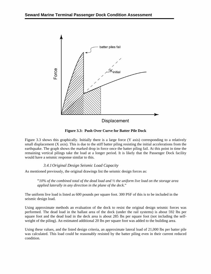
There are two sections of the dock separated by an expansion joint between bents 32 and 33 (see drawings in the appendix). Each of these sections will behave like independent structures in a seismic event. In general the outer or more southerly section of the dock from Bent 33 to 63 is in deeper water and has no building on it. Therefore it has lighter dead loads and longer piling. Because of this the fundamental period of this section of the dock will be longer and it will see less seismic force than the landward section of the dock. The landward section of the dock has shorter piling and is therefore stiffer and has a shorter period. It also contains the abutment and the building. Therefore the landward section of the dock from Bents 1 to 32 will see higher seismic loads. The ARRC Passenger Dock consists of both short and longer period piling. The batter pilings form a triangular braced frame and are by nature stiff with a relatively short fundamental period. The vertical pilings are by nature more flexible with a longer period. Therefore it can be expected that the batter piling will be the primary lateral load resisting element. The California State Lands Commission created a widely cited set of design and evaluation criteria called “Marine Oil Terminal Engineering and Maintenance Standards” or MOTEMS. These have been officially adopted by the State of California and are applicable to marine oil terminals in that state’s waters. While not legally applicable in Alaska, the methods and science behind the standards are helpful in understanding the expected behavior of a wide range of waterfront facilities. MOTEMS describes the seismic performance of a batter pile dock as follows:
“Wharves or piers with ordinary batter piles typically have a very stiff response when subjected to lateral loads in the direction of the batter. The structure often maintains most of its initial stiffness all the way to failure of the first row of batter piles.”
MOTEMS goes on to outline that the batter piles most likely will fail under a significant seismic event and:
“When the row of batter piles fail in tension or shear, stored energy will be released. The structure will therefore experience a lateral displacement demand following the non-ductile pile failures. If the structure can respond to this displacement demand without exceeding other structural limitations, it may be assumed that the structure is stable and will start to respond to further shaking with a much longer period and corresponding lower seismic demands. The wharf structure may therefore be able to sustain larger seismic demands following the loss of the batter piles than before the loss of pile capacity, because of a much softer seismic response.”
Seward Marine Terminal Passenger Dock Condition Assessment
Figure 3.3: Push Over Curve for Batter Pile Dock
Figure 3.3 shows this graphically. Initially there is a large force (Y axis) corresponding to a relatively small displacement (X axis). This is due to the stiff batter piling resisting the initial accelerations from the earthquake. The graph shows the marked drop in force once the batter piling fail. At this point in time the remaining vertical pilings take the load at a longer period. It is likely that the Passenger Dock facility would have a seismic response similar to this.
3.4.1 Original Design Seismic Load Capacity
As mentioned previously, the original drawings list the seismic design forces as: “10% of the combined total of the dead load and ½ the uniform live load on the storage area applied laterally in any direction in the plane of the deck.”
The uniform live load is listed as 600 pounds per square foot. 300 PSF of this is to be included in the seismic design load. Using approximate methods an evaluation of the dock to resist the original design seismic forces was performed. The dead load in the ballast area of the dock (under the rail systems) is about 592 lbs per square foot and the dead load in the deck area is about 285 lbs per square foot (not including the self-weight of the piling). An estimated additional 20 lbs per square foot was added to the building area. Using these values, and the listed design criteria, an approximate lateral load of 21,000 lbs per batter pile was calculated. This load could be reasonably resisted by the batter piling even in their current reduced condition.
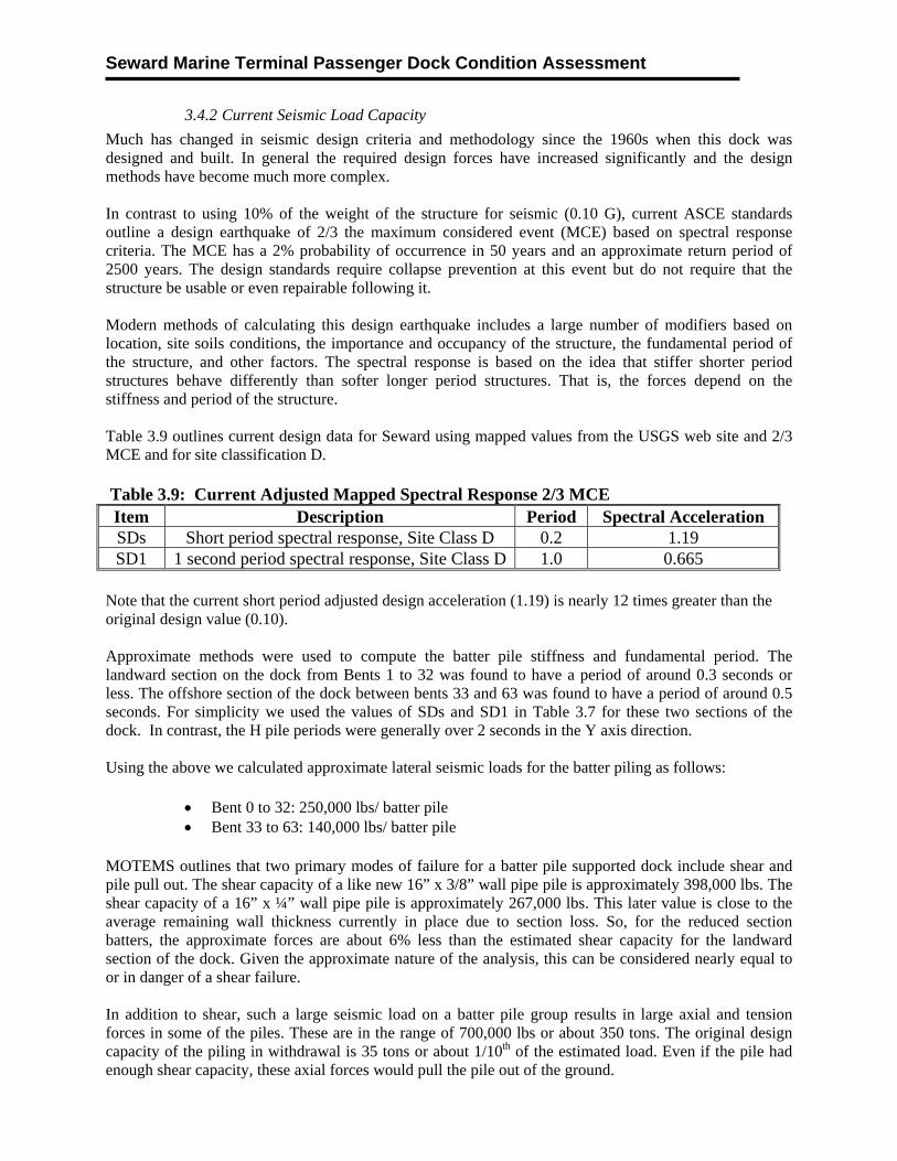
Seward Marine Terminal Passenger Dock Condition Assessment
3.4.2 Current Seismic Load Capacity
Much has changed in seismic design criteria and methodology since the 1960s when this dock was designed and built. In general the required design forces have increased significantly and the design methods have become much more complex. In contrast to using 10% of the weight of the structure for seismic (0.10 G), current ASCE standards outline a design earthquake of 2/3 the maximum considered event (MCE) based on spectral response criteria. The MCE has a 2% probability of occurrence in 50 years and an approximate return period of 2500 years. The design standards require collapse prevention at this event but do not require that the structure be usable or even repairable following it. Modern methods of calculating this design earthquake includes a large number of modifiers based on location, site soils conditions, the importance and occupancy of the structure, the fundamental period of the structure, and other factors. The spectral response is based on the idea that stiffer shorter period structures behave differently than softer longer period structures. That is, the forces depend on the stiffness and period of the structure. Table 3.9 outlines current design data for Seward using mapped values from the USGS web site and 2/3 MCE and for site classification D. Table 3.9: Current Adjusted Mapped Spectral Response 2/3 MCE Item Description Period Spectral Acceleration SDs Short period spectral response, Site Class D 0.2 1.19 SD1 1 second period spectral response, Site Class D 1.0 0.665
Note that the current short period adjusted design acceleration (1.19) is nearly 12 times greater than the original design value (0.10). Approximate methods were used to compute the batter pile stiffness and fundamental period. The landward section on the dock from Bents 1 to 32 was found to have a period of around 0.3 seconds or less. The offshore section of the dock between bents 33 and 63 was found to have a period of around 0.5 seconds. For simplicity we used the values of SDs and SD1 in Table 3.7 for these two sections of the dock. In contrast, the H pile periods were generally over 2 seconds in the Y axis direction. Using the above we calculated approximate lateral seismic loads for the batter piling as follows:
Bent 0 to 32: 250,000 lbs/ batter pile Bent 33 to 63: 140,000 lbs/ batter pile
MOTEMS outlines that two primary modes of failure for a batter pile supported dock include shear and pile pull out. The shear capacity of a like new 16” x 3/8” wall pipe pile is approximately 398,000 lbs. The shear capacity of a 16” x ¼” wall pipe pile is approximately 267,000 lbs. This later value is close to the average remaining wall thickness currently in place due to section loss. So, for the reduced section batters, the approximate forces are about 6% less than the estimated shear capacity for the landward section of the dock. Given the approximate nature of the analysis, this can be considered nearly equal to or in danger of a shear failure. In addition to shear, such a large seismic load on a batter pile group results in large axial and tension forces in some of the piles. These are in the range of 700,000 lbs or about 350 tons. The original design capacity of the piling in withdrawal is 35 tons or about 1/10th of the estimated load. Even if the pile had enough shear capacity, these axial forces would pull the pile out of the ground.
Seward Marine Terminal Passenger Dock Condition Assessment
3.4.3 Liquefaction Potential
The original design criteria are silent on the subject of soil liquefaction. However, there is strong evidence that the site is subject to this condition. The site is an alluvial fan from nearby rivers and has a documented history of liquefaction in seismic from the 1964 event. Saturated sandy material is at high risk for liquefaction. Modern design standards require that this be considered. Preliminary design done recently on concepts for the nearby Freight Dock expansion show piling with embedment’s of over 70 feet, in part due to liquefaction potential. These are far greater than the existing dock’s 35 to 45 feet of embedment. It is likely that the relatively short existing pilings are embedded in the zone of soils that are subject to this condition. Based on this there is a significant risk of damage to this dock due to liquefaction in a seismic event.
Seward Marine Terminal Passenger Dock Condition Assessment
4.0 RECOMMENDATIONS
4.1 General
Structural problems or safety hazards were identified during the condition assessment. Facilities with a rating of 1 or 2 are considered critical or serious and are a high priority for repair or replacement, followed by those with a rating of 3 which should be repaired with moderate urgency. Facilities with a rating of 4 have items that are recommended for repair, but are the lowest priority. Facilities rated 5 or 6 do not have obvious structural or safety repairs required; however, those facilities with a rating of 5 had some deterioration and moderate defects observed and these items should be monitored on a regular basis.
4.2 Priority Repairs
Cathodic Protection System As mentioned above, there is the potential for loss of structural capacity of the piling due to corrosion. Without cathodic protection this could happen in 5 to 10 years or less. Based on this, the first priority is to inspect, repair, and operate the CP system at full capacity and efficiency and to then aggressively maintain it. The following is recommended:
A full inspection of the CP system by a corrosion specialist. This will focus on items that need to be repaired for full system operation.
Develop and execute a detailed maintenance and operation program of the CP system. This will include a schematic of the system and written operations, inspection, and maintenance procedures.
ARRC staff who operate and inspect the CP system should receive National Association of Corrosion Engineers (NACE) training.
Steel Pile Repairs The next priority recommendation is a fairly aggressive pile rehabilitation project involving repair sleeves and jackets. This would involve cleaning the piling, installing a synthetic jacket around it (possibly including reinforcement), and pumping grout into the annulus. There are a number of commercially available products on the market for this. See appendix for some information on this. The jacket systems have several advantages including:
The jacket provides a barrier to chlorides (seawater) greatly reducing the corrosion potential.
The grout provides both a barrier and an alkaline environment that reduces corrosion potential.
The jacket can be extended into the splash zone (above the water surface) to protect areas a CP system cannot reach.
Reinforcing can be added to rebuild structural capacity of the piling.
Because there are approximately 1800 piling in this dock, repairs might be done in phases over a number of years. For example 300 piling could be done each year for six years.
Sheet Pile Repairs As mentioned previously the sheet pile abutment has serious section loss. Portions of this wall are near failure based on very thin remaining wall thickness. The wall is generally in the splash zone and above the area where the CP system could offer protection. The sheet pile abutment should be sand or water blasted and coated. This would slow the corrosion. It is recommended that the remaining wall be used as
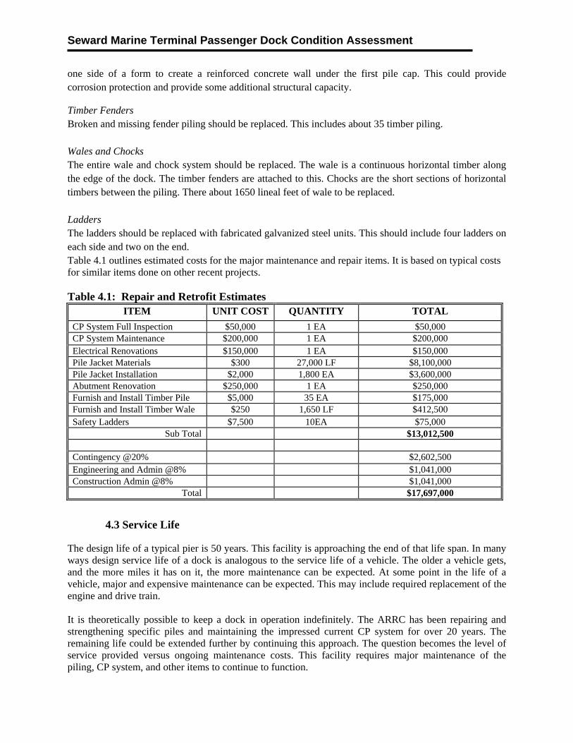
Seward Marine Terminal Passenger Dock Condition Assessment
one side of a form to create a reinforced concrete wall under the first pile cap. This could provide corrosion protection and provide some additional structural capacity.
Timber Fenders Broken and missing fender piling should be replaced. This includes about 35 timber piling. Wales and Chocks The entire wale and chock system should be replaced. The wale is a continuous horizontal timber along the edge of the dock. The timber fenders are attached to this. Chocks are the short sections of horizontal timbers between the piling. There about 1650 lineal feet of wale to be replaced. Ladders The ladders should be replaced with fabricated galvanized steel units. This should include four ladders on each side and two on the end. Table 4.1 outlines estimated costs for the major maintenance and repair items. It is based on typical costs for similar items done on other recent projects. Table 4.1: Repair and Retrofit Estimates
ITEM UNIT COST QUANTITY TOTAL
CP System Full Inspection $50,000 1 EA $50,000 CP System Maintenance $200,000 1 EA $200,000 Electrical Renovations $150,000 1 EA $150,000 Pile Jacket Materials $300 27,000 LF $8,100,000 Pile Jacket Installation $2,000 1,800 EA $3,600,000 Abutment Renovation $250,000 1 EA $250,000 Furnish and Install Timber Pile $5,000 35 EA $175,000 Furnish and Install Timber Wale $250 1,650 LF $412,500 Safety Ladders $7,500 10EA $75,000
Sub Total $13,012,500 Contingency @20% $2,602,500 Engineering and Admin @8% $1,041,000 Construction Admin @8% $1,041,000
Total $17,697,000
4.3 Service Life
The design life of a typical pier is 50 years. This facility is approaching the end of that life span. In many ways design service life of a dock is analogous to the service life of a vehicle. The older a vehicle gets, and the more miles it has on it, the more maintenance can be expected. At some point in the life of a vehicle, major and expensive maintenance can be expected. This may include required replacement of the engine and drive train. It is theoretically possible to keep a dock in operation indefinitely. The ARRC has been repairing and strengthening specific piles and maintaining the impressed current CP system for over 20 years. The remaining life could be extended further by continuing this approach. The question becomes the level of service provided versus ongoing maintenance costs. This facility requires major maintenance of the piling, CP system, and other items to continue to function.
Seward Marine Terminal Passenger Dock Condition Assessment
In terms of level of service, the pile configuration is out dated and cannot be made compliant with current seismic design standards. Further, the functionality of the dock for its current use should be considered. This facility was originally designed and built as an intermodal rail dock. The primary use of the dock is now centered on passenger services and cruise ships. While cargo operations are still possible, the on dock rails and transit building are no longer used for this. Therefore these items may be considered functionally obsolete, at least for their originally intended purpose. Based on the above the ARRC should consider the costs of major maintenance versus replacement costs and desired level of service.
4.4 Replacement Option
The ARRC may plan for major capital expenditures in terms of a replacement dock. A concept level drawing of a new dock, tailored to the passenger cruise ship industry, is shown in the appendix. This includes a pile supported concrete deck platform dock designed to modern standards. Two mooring dolphins to the south are shown with a catwalk system. A new terminal building is included. This dock has the following features:
It is longer and narrower than the existing dock. The new dock is shown to be nominally 1,006’ long and 116’ feet wide. This is long enough to provide berthing for nearly the entire side of a typical cruise ship and wide enough for turning around tour buses.
The berths will be dredged to -42 feet MLLW. Two mooring dolphins are shown, one at 100’ and one at 200’ from the offshore end of the dock.
These are connected via a catwalk. A two story 7000 square foot terminal building is shown on the shoreward end of the dock. This
has preliminary dimensions of 50’ x 115’ in plan view. The building would provide for passenger services on the ground floor and office space on the second floor.
The building is situated to provide a gate / secure access point to the dock similar to the existing terminal building.
A 33’ wide access lane is provided on each side of the building for vehicular traffic. Four each dock slots are provided to aid in all-tide baggage handling. Fenders are provided at 60’ on center down each side of the dock. Utilities include lighting, electrical, and potable water for the vessels. Cathodic protection is provided by sacrificial anodes attached to each pile and fender panel. The dock would be supported on galvanized steel pipe piling and would include a concrete deck. The load capacity of the dock would be sufficient for cruise ship and light cargo operations. Pile
bents are 40 feet on center and the channel section deck panels are utilized. Concept level cost estimates are shown in table 4.2 and 4.3. These should be used to provide the general magnitude of a replacement dock and terminal building. A more detailed study could provide more refinements to the concept and a higher level of confidence in the estimated costs. If heavy cargo capacity is required a multipurpose dock could be built. The load capacity of the concept dock could be increased by decreasing the pile bent spacing from 40 feet on center to 20 feet on center and using higher capacity concrete deck panels.
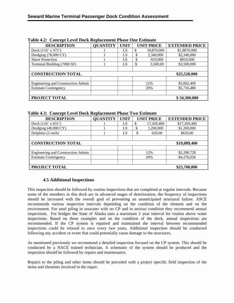
Seward Marine Terminal Passenger Dock Condition Assessment
Table 4.2: Concept Level Dock Replacement Phase One Estimate
DESCRIPTION QUANTITY UNIT UNIT PRICE EXTENDED PRICEDock (116’ x 375’) 1 LS $ 18,870,000 $1,8870,000 Dredging (78,000 CY) 1 LS $ 2,340,000 $2,340,000 Shore Protection 1 LS $ 810,000 $810,000 Terminal Building (7000 SF) 1 LS $ 3,500,00 $3,500,000
CONSTRUCTION TOTAL $25,520,000
Engineering and Construction Admin 12% $3,062,400 Estimate Contingency 20% $5,716,480
PROJECT TOTAL $ 34,300,000
Table 4.3: Concept Level Dock Replacement Phase Two Estimate
DESCRIPTION QUANTITY UNIT UNIT PRICE EXTENDED PRICEDock (116’ x 631’) 1 LS $ 17,269,400 $17,269,400 Dredging (40,000 CY) 1 LS $ 1,200,000 $1,200,000 Dolphins (2 each) 1 LS $ 620,00 $620,00
CONSTRUCTION TOTAL $19,089,400
Engineering and Construction Admin 12% $2,290,728 Estimate Contingency 20% $4,276,026
PROJECT TOTAL $25,700,000
4.5 Additional Inspections
This inspection should be followed by routine inspections that are completed at regular intervals. Because some of the members in this dock are in advanced stages of deterioration, the frequency of inspections should be increased with the overall goal of preventing an unanticipated structural failure. ASCE recommends various inspection intervals depending on the condition of the element and on the environment. For steel piling in seawater with no CP and in serious condition they recommend annual inspections. For bridges the State of Alaska uses a maximum 2 year interval for routine above water inspections. Based on these examples and on the condition of the dock, annual inspections are recommended. If the CP system is repaired and maintained the interval between recommended inspections could be relaxed to once every two years. Additional inspection should be conducted following any accident or event that could potentially cause damage to the structures. As mentioned previously we recommend a detailed inspection focused on the CP system. This should be conducted by a NACE trained technician. A schematic of the system should be produced and the inspection should be followed by repairs and maintenance. Repairs to the piling and other items should be preceded with a project specific field inspection of the items and elements involved in the repair.
Seward Marine Terminal Passenger Dock Condition Assessment
4.6 Additional Analysis
The ARRC may consider additional analysis as follows: Seismic: Approximate methods were used to estimate the seismic performance of the dock. This analysis outlined that the dock is at significant risk for damage or failure in a seismic event. Additional and more detailed analysis may help to better outline the expected performance in a range of events. This would include creating a structural model of the entire dock and subjecting it to various events with differing return periods. In addition the soils at the site could be analyzed for liquefaction potential. These could help the ARRC better understand the seismic risk. Special Load Cases: If the dock is used for heavy loads, for example cargo lifted from a vessel with a crane, additional analysis should be completed for that specific equipment and load case.
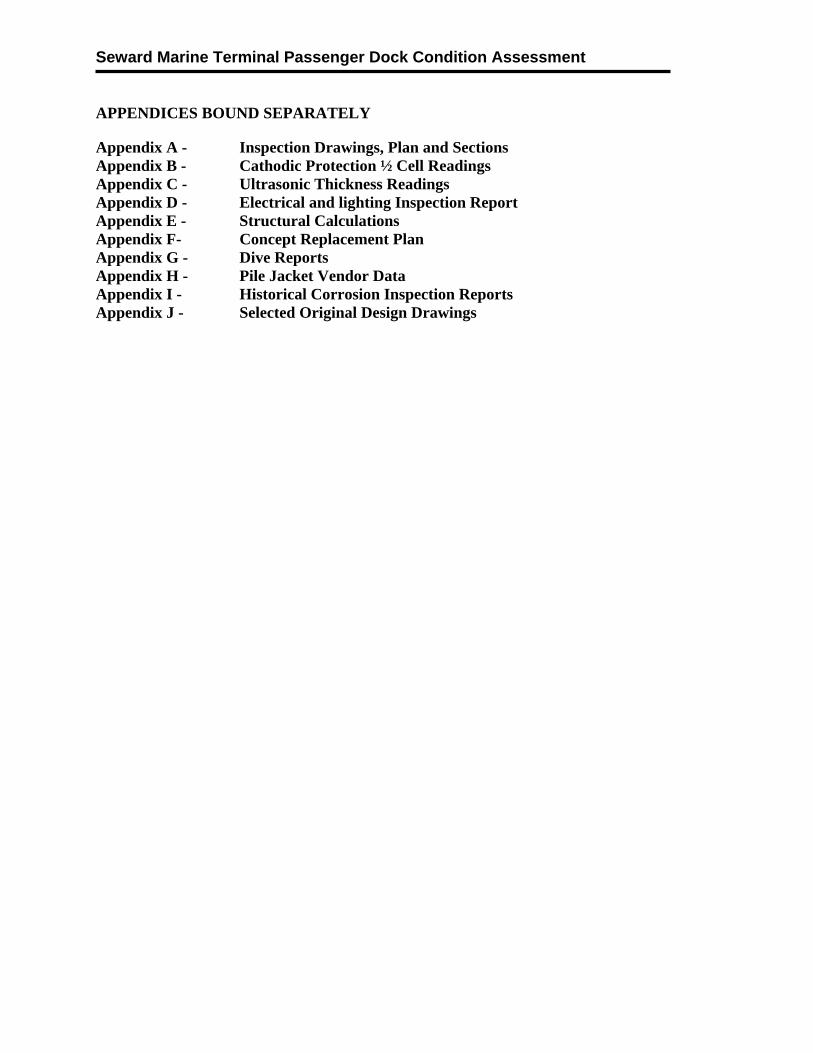
Seward Marine Terminal Passenger Dock Condition Assessment
APPENDICES BOUND SEPARATELY
Appendix A - Inspection Drawings, Plan and Sections Appendix B - Cathodic Protection ½ Cell Readings Appendix C - Ultrasonic Thickness Readings Appendix D - Electrical and lighting Inspection Report Appendix E - Structural Calculations Appendix F- Concept Replacement Plan Appendix G - Dive Reports Appendix H - Pile Jacket Vendor Data Appendix I - Historical Corrosion Inspection Reports Appendix J - Selected Original Design Drawings