Design aspects of launch vehicle sizing including air-breathing propulsion Design aspects of launch...
13
http://pig.sagepub.com/ Engineering Engineers, Part G: Journal of Aerospace Proceedings of the Institution of Mechanical http://pig.sagepub.com/content/220/5/487 The online version of this article can be found at: DOI: 10.1243/09544100JAERO30 2006 220: 487 Proceedings of the Institution of Mechanical Engineers, Part G: Journal of Aerospace Engineering M Sundaresan Design aspects of launch vehicle sizing including air-breathing propulsion Published by: http://www.sagepublications.com On behalf of: Institution of Mechanical Engineers can be found at: Proceedings of the Institution of Mechanical Engineers, Part G: Journal of Aerospace Engineering Additional services and information for http://pig.sagepub.com/cgi/alerts Email Alerts: http://pig.sagepub.com/subscriptions Subscriptions: http://www.sagepub.com/journalsReprints.nav Reprints: http://www.sagepub.com/journalsPermissions.nav Permissions: http://pig.sagepub.com/content/220/5/487.refs.html Citations: What is This? - May 1, 2006 Version of Record >> by guest on January 25, 2013 pig.sagepub.com Downloaded from
-
Upload
independent -
Category
Documents
-
view
1 -
download
0
Transcript of Design aspects of launch vehicle sizing including air-breathing propulsion Design aspects of launch...

http://pig.sagepub.com/Engineering
Engineers, Part G: Journal of Aerospace Proceedings of the Institution of Mechanical
http://pig.sagepub.com/content/220/5/487The online version of this article can be found at:
DOI: 10.1243/09544100JAERO30
2006 220: 487Proceedings of the Institution of Mechanical Engineers, Part G: Journal of Aerospace EngineeringM Sundaresan
Design aspects of launch vehicle sizing including air-breathing propulsion
Published by:
http://www.sagepublications.com
On behalf of:
Institution of Mechanical Engineers
can be found at:Proceedings of the Institution of Mechanical Engineers, Part G: Journal of Aerospace EngineeringAdditional services and information for
http://pig.sagepub.com/cgi/alertsEmail Alerts:
http://pig.sagepub.com/subscriptionsSubscriptions:
http://www.sagepub.com/journalsReprints.navReprints:
http://www.sagepub.com/journalsPermissions.navPermissions:
http://pig.sagepub.com/content/220/5/487.refs.htmlCitations:
What is This?
- May 1, 2006Version of Record >>
by guest on January 25, 2013pig.sagepub.comDownloaded from

Design aspects of launch vehicle sizing includingair-breathing propulsionM Sundaresan
ISRO VSSC, Engineer ‘G’ gsLVM3 PROJECT, Vikram Sarabhai Space Centre, Trivandrum, Kerala, 695022, India.
email: [email protected]
The manuscript was received on 21 July 2005 and was accepted after revision for publication on 8 May 2006.
DOI: 10.1243/09544100JAERO30
Abstract: The overall sizing of launch vehicles is of interest, especially when air-breathing isalso included. The sizing of a launch vehicle is dictated by the State of Art technologies presentand the need to match the challenging demands of high-payload fraction, low cost, and alsoensure reliability. This paper presents some of the important design requirements. An idealvelocity approach, which assumes various velocity losses, is generally followed for initial vehiclesizing. However, as this approach is approximate and sometimes incorrect, a new concept ofaccounting the drag and thrust losses during the atmospheric phase for conventional rocketsand air-breathing launch vehicles using scramjet propulsion is evolved complementing theideal velocity sizing approach. A simplistic two-dimensional trajectory simulation programwith graphics for quick interactive design was developed for this purpose. The air-breathinglaunch vehicle trajectory is split into three flight phases. The sizing of the vehicle considering,especially, the intermediate air-breathing regime is also dealt with. A method to determinethe maximum-load envelope expressed in terms of the product of flight dynamic pressureand angle of attack, namely Q-alpha, for all weather launches useful for initial design purposesis also suggested. The design program meant for initial design sizing purposes gives a quickinsight on the vehicle performance prior to detailed design with minimum basic vehicle datafor conventional rockets and also for air-breathing scramjet vehicles. The various design factors,such as optimum velocity requirement for two stage to orbit vehicles and the sizing requirementof the orbital stage after end of air-breathing phase, are also discussed through representativetypical values highlighting the design sensitivities.
Keywords: launch vehicle design, air-breathing vehicle sizing, trajectory design sizing program,launch vehicle performance
1 INTRODUCTION
The overall sizing of launch vehicles to meet aparticular mission requirement is an importantaspect, especially in the initial vehicle design phase.The choice of the propulsion system and its sizing,apportionment of the stage system structuralmasses and deriving a broad mission sequence isvery important, as it has a very large impact on thelaunch vehicle development programme. As theoverall reliability increases with lower number ofstage systems, it is also necessary to reduce thesystem complexities and maintain operationalconvenience. In actual practice, the selection of a
particular launch vehicle configuration meeting adefined mission is an elaborate painstaking process,which also considers the state of art, developmentfeasibility, cost and schedule aspects.
Towards the previous-mentioned factors, nume-rous studies are reported in the published literatureon the various aspects of launch vehicle designincluding cost and reliability. As the area of launchvehicle design is vast, studies are done in variousphases from the initial configuration design to thedetailed design stage including interactive designdisciplines and overall optimization studies. Hence,it would be very difficult for any single paper tocover the whole gamut of design issues. Still many
487
JAERO30 # IMechE 2006 Proc. IMechE Vol. 220 Part G: J. Aerospace Engineering
by guest on January 25, 2013pig.sagepub.comDownloaded from

papers have addressed the overall configurationdesign aspect to a large extent.
Ryan and Townsend [1] address the salient per-formance parameters of the space shuttle andSaturn vehicle as a benchmark example, startingfrom the idealized rocket performance equation todetermine the key design drivers. Robustness is thekey to uncoupling the design factors so that optimi-zation can occur, but typically robust designs definelow-performance systems and also the future spacelaunch vehicles must develop new technologies toreshape the design parameter sensitivities of robust-ness and performance functions [1]. Detailed studieson the conceptual design of two types of reusabletwo stage to orbit (TSTO) vehicles considering theimpact of mission requirements and constraints aredealt with in reference [2].
Olds [3] dwells comprehensively on the design of areusable single stage to orbit (SSTO) vehicle makinguse of rocket-based combined cycle (RBCC), whichcombines the operating modes of an ejector,ramjet, scramjet, and rocket in a single engine. TheRBCC SSTO design uses various advanced concep-tual disciplinary areas on performance, aerody-namics, aero-heating, propulsion, and weightestimation [3]. Incidentally, the author has derivedinspiration from reference 3 for writing the presentpaper as a SSTO air-breathing rocket (ABR) vehiclehad served as the benchmark for the TSTO versionsusing scramjet propulsion. There are also variousreported literature in each or selective areas ofdesign, to name a few like natural environment defi-nition for aerospace launch vehicle design given inreference [4] and atmospheric wind models [5]related to aerospace launch vehicle design.
The purpose of this paper is to discuss some ofthe important design parameters and sensitivitiesthat need to be addressed during the initial con-figuration design phase itself, so as to arrive atthe most appropriate workable specifications forthe propulsion modules and stages besides satis-fying the vehicle configuration requirements onstaging and overall vehicle drag and loads withrespect to Q-alpha load limits. The paper addressestowards initial sizing of launch vehicles with andwithout air-breathing. A simplistic design approachfor sizing the launch vehicle complementing anideal velocity method is highlighted in the followingsections. The paper has attempted to make use oftypical design values or factors to highlight thedesign sensitivities in order to have a quantitativefeel, especially for air-breathing vehicles usingscramjet propulsion. The aim of the design is toarrive at a skeletal wire frame type of trajectory,which is feasible, leading to system specificationafter that detailing and detailed design studiescan follow.
2 DESIGN CONSIDERATIONS
Some of the important considerations for launchvehicle sizing are mainly the following: (a) fixing thenumber of stages; (b) choice of propulsion systemand sizing; (c) range safety constraints; (d) state-of-art technologies existing and near time goals; (e)reliability and cost; (f) desired payload maximized tothe extent possible; and (g) ground and launchsupport constraints and other relevant factors. In thepresent paper that addresses on the design consider-ations and sensitivities, certain assumptions aremade with respect to the ideal velocity, structural fac-tors, and propulsion Isp for various stages mainly forhighlighting a particular trend or variation andemphasizing a particular design feature. The idealvelocity required to meet a particular mission givenin equation (1) can be used for initial vehicle sizing
ideal velocity(VI ) ¼ VORB:VEL þ VLOSSES+ VE:ROT (1)
The ideal velocity should be suitably chosen by thedesigner on the basis of experience on the various vel-ocity losses due to drag, thrust, gravity losses, type ofpropulsion system, flight sequence, range safetyfactors, and launch azimuth. The ideal velocity forwhich the vehicle is to be sized is given by
vehicle ideal velocity(VI ) ¼ g �
X
n
i¼1
Ispi � logeWi
WFi
(1a)
The optimum sizing of the stageswith respect to thepropulsion system depends on the staging velocity foreach stage. The optimum staging velocity will dependon the stage structural factors and propulsion systemperformance, namely Isp and ideal velocity assumed.On the basis of the ideal velocity sizing approach, theeffect of staging velocity on the payload fraction for aTSTO vehicle is shown in Fig. 1 for an expendable first
Fig. 1 Effect of staging velocity with expendable first
stage
488 M Sundaresan
Proc. IMechE Vol. 220 Part G: J. Aerospace Engineering JAERO30 # IMechE 2006
by guest on January 25, 2013pig.sagepub.comDownloaded from

stage. The ideal velocity assumed is 9600 m/s, and thepayload fraction (as a typical example case) is plottedfor an all-cryogenic TSTO vehicle, considering thestage structural factors for the expendable and reusa-ble stage as 0.12 and 0.25, respectively. The idealvelocity for the TSTO vehicle given in equation (2)has been derived suitably in terms of the first stagetotal mass WT1 and WPAYL so as to arrive at thepayload fraction percentage that corresponds to aparticular staging velocity assumed for plotting thegraph in Fig. 1, for a known ideal velocity
(VI) ¼ g � Isp1 � logeWO
WO !WT1(1! s1)þ g � Isp2
� logeWO !WT1
(WO !WT1!WPAYL)s2 þWPAYL
(2)
The first stage could also be reusable and can be ofdifferent types, with respect to type of landing andits location, namely land or sea recovery at predeter-mined sites. The reusable stage structural factors arebound to vary say, if it is to land back with returnfuel supported by suitable propulsion systemsdepending on whether it is to be recovered as asub-orbital or orbital stage. The designer has tochoose the suitable stage structural factors felt asappropriate for a particular mission.
From Fig. 1, the optimum staging velocity for thefirst stage is �4500 m/s and the payload fraction is5.8 per cent for an expendable TSTO. Similarly, theoptimum staging velocity for a reusable first stagecan be arrived at. When there are range safety con-siderations, there is every possibility that the
optimum staging velocity derived thus may posespent stage impact problems. Hence, under suchcases, a near optimum staging velocity giving themaximum payload fraction can be suitably chosen,which can also consider the range safety consider-ations of the spent booster stage impact.
Generally, the initial sizing of the rocket is based onthe ideal velocity requirement derived by experiencefrom various trajectory and mission studies. Theideal velocity will include the various losses due toatmospheric drag, thrust losses in atmosphere, gravitylosses including maneuvers, and so on. An overallmission profile for a normal trajectory of an expen-dable rocket versus an ABR trajectory is shown inFig. 2.
Figure 2 also shows the reusability of the first stagelanding at a predetermined site, whereas the secondstage could be an expendable stage or reusable,which would depend on the mission requirementsenvisaged. For the air-breathing trajectory usingscramjets, it can be considered to be essentiallyin three phases namely: (a) ascent phase till Machnumbers 2–4 (phase-I); (b) ABR phase that is fromend of phase-I to Mach numbers that can be ashigh as .12 (phase-II); and (c) pull-up to orbitphase in LEO (phase-III).
The ascent phase could be a pure rocket, ejector-ram rocket or turbo-ram rocket, etc. and the take-off mode could be either horizontal or vertical. Theair-breathing phase (phase-II) is essentially therocket flight through atmosphere preferably altitudesbetween 10 and 35 km. The vehicle will be gainingthe required velocity or Mach number, say 12, the
Fig. 2 Typical trajectory of expendable rocket versus ABR
Design aspects of launch vehicle sizing 489
JAERO30 # IMechE 2006 Proc. IMechE Vol. 220 Part G: J. Aerospace Engineering
by guest on January 25, 2013pig.sagepub.comDownloaded from
maximum possible on the basis of ABR technologyand thermal constraints. The flight will be at verylow angle of attacks just enough to sustain a steadyaltitude gain within the desired constant dynamicpressure limit �75 kPa and as low as 30 kPa duringthe end of ABR phase. Phase-II is critical in ABRvehicles. Depending on the terminal Mach numberat the end of the ABR phase-II, the upper secondstage mass and thrust requirements will be largelyinfluenced. Lower the terminal ABR Mach number,greater will be the challenge on the propulsionsystem thrust rating requirements for the upperstage sizing.
An SSTO vehicle using RBCC has an in-built pro-pulsion system capable of delivering advantageouslylarger thrust even during the beginning of phase-III,i.e. the rocket pull-up to orbit phase [3]. In the case ofTSTO rocket configurations, the above advantage,namely higher thrust usually required during begin-ning of phase-III regime, could become a constraintand sometimes difficult to achieve. Therefore, as anSSTO-ABR vehicles require lower stage structuralfactors and demanding propulsion requirements,the SSTO design will provide immense challengeand will be the dream and driving force for futureABR vehicle systems.
3 DESIGN SIZING PROGRAM
Although the initial sizing of the vehicle by the idealvelocity approach is required, it is very approximate,and sometimes the vehicle so configured may beincorrect, especially for ABR vehicles due to theerrors in accounting for the vehicle drag with itseffect on vehicle velocity, and gravity losses, astrong function of the individual stage thrust levels.Hence further to the ideal velocity sizing approach,a two-dimensional trajectory design sizing programwas developed considering the flat earth basicallyfor arriving towards a feasible vehicle configuration.The program needs the initial sizing of the individualstages including the stage structural factors, propul-sion data, vacuum Isp of stages, and total take-offmass as derived from ideal velocity estimates forconventional rockets highlighted in the earlier sec-tion. For ABR vehicles, the baseline input require-ments to carry out the trajectory analyses isdiscussed in the following sections.
3.1 Additional design requirementsfor ABR rockets
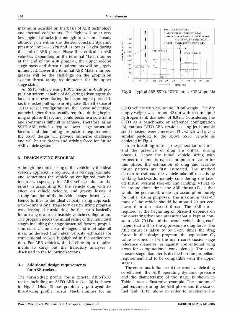
The thrust/drag profile for a general ABR-TSTOrocket including an SSTO-ABR rocket [3] is shownin Fig. 3. Olds [3] has graphically portrayed thethrust/drag profile versus Mach number for an
SSTO vehicle with 230 tonne lift-off weight. The dryempty weight was around 42 ton with a core liquidhydrogen tank diameter of 6.8 m. Considering theSSTO as a benchmark or reference configuration[3], various TSTO-ABR versions using jettisionablesolid boosters were conceived [7], which will give asimilar payload to the above SSTO vehicle asdepicted in Fig. 4.
In air-breathing rockets, the generation of thrustand the presence of drag are critical duringphase-II. Hence the initial vehicle sizing withrespect to diameter, type of propulsion system forthis phase, the estimation of drag and feasiblethrust pattern are first estimated. The methodchosen to estimate the vehicle take-off mass is byworking backwards, namely considering the take-off thrust (vertical take-off and landing, VTOL) tobe around three times the ABR thrust (TABR) thatwould be generated, a design assumption purelyfor initial sizing purposes. The maximum take-offmass of the vehicle should be around 20 per centlower than the take-off thrust. The ABR thrustrequired at the beginning of phase-II depends onthe operating dynamic pressure that is kept at con-stant �60–70 kPa and the overall vehicle drag coef-ficient that will fix the approximate drag force. TheABR thrust is taken to be 2–2.5 times the dragforce. In the design program, the equivalent CD
value assumed is for the main core/booster stagereference diameter (as against conventional wingareas for computational convenience). The core/booster stage diameter is decided on the propellantrequirement and to be compatible with the upperstages.
The enormous influence of the overall vehicle dragco-efficient, the ABR operating dynamic pressureand the diameter/size of the stage, is shown inTable 1 as an illustrative example. The amount offuel required during the ABR phase and the size offuel tank (LH2) alone in order to accelerate the
Fig. 3 Typical ABR-SSTO/TSTO: thrust /DRAG profile
490 M Sundaresan
Proc. IMechE Vol. 220 Part G: J. Aerospace Engineering JAERO30 # IMechE 2006
by guest on January 25, 2013pig.sagepub.comDownloaded from

vehicle from Mach number 3 to 10 as a typical study[7] is shown in Table 1. It is seen from Table 1 that theABR stage fuel length to diameter ratio is lower, whenthe overall drag coefficients are lower and the vehicleoperates at lower dynamic pressures in phase-IIregime. For various vehicle stage/booster diameters,dynamic pressures and drag coefficients the corre-sponding propellant required for the booster phaseand ABR cruise till Mach number 10 with solid pro-pellant for the booster phase is worked out asshown in Table 1.
For TSTO vehicle, the booster will boost the vehicleto Mach number 3 or so, and is assumed to be a jet-tisionable solid-rocket motor. However, it could be ahigh-pressure liquid propellant engine or, inaddition, can also work in the ejector mode-RBCCfor an SSTO vehicle [3]. For Turbo-fan rocket takingoff in the horizontal mode and landing horizontally;the T/W would be much lower and will be nearTABR value, and is not discussed in the Table 1. Thequantity of LH2 fuel required during the ABRphase-II is estimated on the basis of a average
Fig. 4 Air-breathing stage vehicle configuration (schematic)
Table 1 Sizing of typical air-breathing vehicles (for VTOL launch vehicle)
DIA (m)
Dynamicpressure(kPa)
Co-efficientof drag CD"
Drag(kN)
ABR thrust(kN) 2.5 �
DRAG
Boosterthrust � (kN)3 � ABRthrust
MaxT.O.mass (ton)B.T/1.2 � g
Propellantrequiredto Mach � 3(ton) solid
Fuel LH2
for ABRMach 3–10 (ton)
Fueltank L/Dratio
2.8 50 1.2 366 915 2740 228 100.0 22.6 18.550 0.35 107 267 801 67 29.2 6.3 5.2530 1.2 220 550 1650 137 60.0 13.7 11.1
4.0 50 1.2 746 1865 5600 466 204.0 46.3 12.950 0.35 217 544 1640 136 59.5 13.7 3.630 1.2 449 1125 3370 280 122.0 28.0 7.7
5.0 50 0.35 340 850 2550 213 93 21.2 2.830 1.2 700 1754 5260 438 191 44.5 6.1
6.8 30 0.35 360 920 2760 230 �76 23.0 1.1SSTO3 (LH2þ LOX)
Note: "REF DIA taken for booster/upper stage DIA quantitiative estimates are only indicative in nature.
Design aspects of launch vehicle sizing 491
JAERO30 # IMechE 2006 Proc. IMechE Vol. 220 Part G: J. Aerospace Engineering
by guest on January 25, 2013pig.sagepub.comDownloaded from
air-breathing Isp of �1700 s in order to get theadditional velocity from Mach number 3 to 10.Hence we may broadly conclude that the LH2 fueltank size reduces considerably with lower dynamicpressure and lower drag coefficient. Hence if theABR configuration does not have a low aero-dragcoefficients and the dynamic pressures are even inthe high range of 60–80 kPa, then the vehicledesign could become impossible. Ideally, we wouldrequire a high thrust (which is a function of vehicledynamic pressure) and with a very low overall dragco-efficient. This is a very challenging requirement,as it has to consider the intake sizing and positioning,the booster phase, and orbital phase stage sizingrequirement besides the severe aerodynamic heatingenvironment. Hence, the ABR configuration designrequires the thrust levels to be properly matched atvarious flight phases in order to ensure the desiredvehicle performance. The overall ABR vehicle con-figuration design is difficult, especially for multi-stages and on the arrangement of stages whether itis in tandem or parallel.
3.2 Conventional rockets
3.2.1 Aerodynamic velocity losses
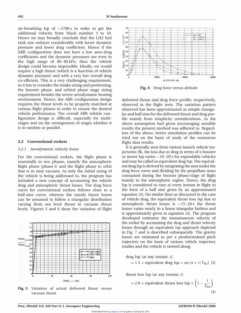
For the conventional rockets, the flight phase isessentially in two phases, namely the atmosphericflight phase (phase-I) and the flight phase to orbitthat is in near vacuum. As only the initial sizing ofthe vehicle is being addressed to, the program hasincluded a new concept of accounting the vehicledrag and atmospheric thrust losses. The drag forcecurve for conventional rockets follows close to ahalf-sine curve, whereas the nozzle thrust lossescan be assumed to follow a triangular distributionvarying from sea level thrust to vacuum thrustlevels. Figures 5 and 6 show the variation of flight
delivered thrust and drag force profile, respectively,observed in the flight tests. The variation patternobserved has been approximated as simple triangu-lar and half sine for the delivered thrust and drag pro-file mainly from simplicity considerations. As theabove assumption had given encouraging sensibleresults the present method was adhered to. Regard-less of the above, better simulation profiles can betried out on the basis of study of the numerousflight data results.
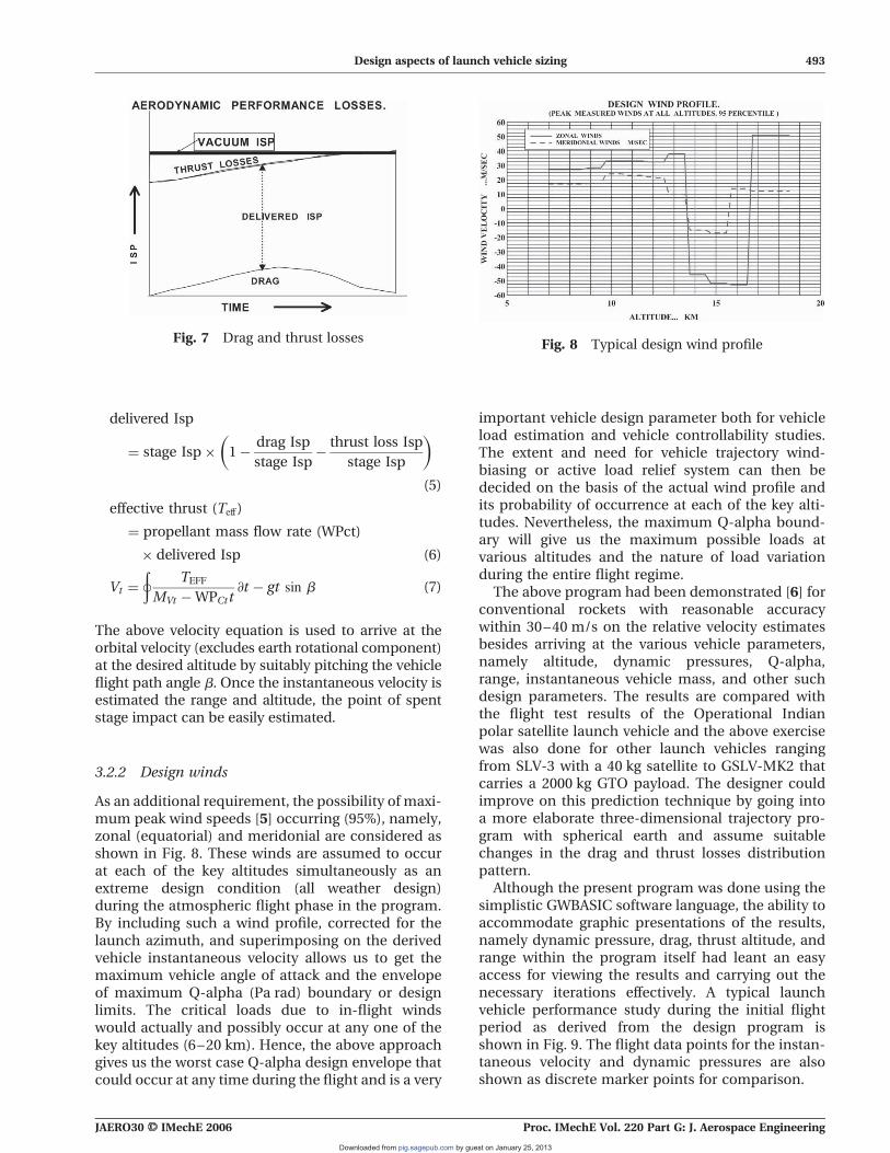
It is generally seen from various launch vehicle tra-jectories [5], the loss due to drag in terms of a boosteror motor Isp varies �10–20 s for expendable vehiclesandmay be called as equivalent drag Isp. The equival-ent drag Isp is derived by integrating the areaunder thedrag force curve and dividing by the propellant massconsumed during the booster phase/stage of flightmainly in the atmospheric region. Hence, the dragIsp is considered to vary at every instant in flight inthe form of a half sine given by an approximatedequation (3). On similar lines as discussed in the caseof vehicle drag, the equivalent thrust loss Isp due toatmospheric thrust losses is �15–20 s the thrustlosses varies nearly in a linear triangular fashion andis approximately given in equation (4). The programdeveloped estimates the instantaneous velocity ofthe rocket by accounting the drag and thrust velocitylosses through an equivalent Isp approach depictedin Fig. 7 and is described subsequently. The gravitylosses are estimated as per a predetermined pitchtrajectory on the basis of various vehicle trajectorystudies and the vehicle is steered along
drag Isp (at any instant, t)
¼ 1:5� equivalent drag Isp� sin (p� t=TBO) (3)
thrust loss Isp (at any instant, t)
¼ 2:0� equivalent thrust loss Isp� 1!t
TBO
! "
(4)Fig. 5 Variation of actual delivered thrust versus
vacuum thrust
Fig. 6 Drag force versus altitude
492 M Sundaresan
Proc. IMechE Vol. 220 Part G: J. Aerospace Engineering JAERO30 # IMechE 2006
by guest on January 25, 2013pig.sagepub.comDownloaded from
delivered Isp
¼ stage Isp� 1!drag Isp
stage Isp!thrust loss Isp
stage Isp
! "
(5)
effective thrust (Teff)
¼ propellant mass flow rate (WPct)
� delivered Isp (6)
Vt ¼
þ
TEFF
MVt !WPCtt@t ! gt sin b (7)
The above velocity equation is used to arrive at theorbital velocity (excludes earth rotational component)at the desired altitude by suitably pitching the vehicleflight path angle b. Once the instantaneous velocity isestimated the range and altitude, the point of spentstage impact can be easily estimated.
3.2.2 Design winds
As an additional requirement, the possibility of maxi-mum peak wind speeds [5] occurring (95%), namely,zonal (equatorial) and meridonial are considered asshown in Fig. 8. These winds are assumed to occurat each of the key altitudes simultaneously as anextreme design condition (all weather design)during the atmospheric flight phase in the program.By including such a wind profile, corrected for thelaunch azimuth, and superimposing on the derivedvehicle instantaneous velocity allows us to get themaximum vehicle angle of attack and the envelopeof maximum Q-alpha (Pa rad) boundary or designlimits. The critical loads due to in-flight windswould actually and possibly occur at any one of thekey altitudes (6–20 km). Hence, the above approachgives us the worst case Q-alpha design envelope thatcould occur at any time during the flight and is a very
important vehicle design parameter both for vehicleload estimation and vehicle controllability studies.The extent and need for vehicle trajectory wind-biasing or active load relief system can then bedecided on the basis of the actual wind profile andits probability of occurrence at each of the key alti-tudes. Nevertheless, the maximum Q-alpha bound-ary will give us the maximum possible loads atvarious altitudes and the nature of load variationduring the entire flight regime.
The above program had been demonstrated [6] forconventional rockets with reasonable accuracywithin 30–40 m/s on the relative velocity estimatesbesides arriving at the various vehicle parameters,namely altitude, dynamic pressures, Q-alpha,range, instantaneous vehicle mass, and other suchdesign parameters. The results are compared withthe flight test results of the Operational Indianpolar satellite launch vehicle and the above exercisewas also done for other launch vehicles rangingfrom SLV-3 with a 40 kg satellite to GSLV-MK2 thatcarries a 2000 kg GTO payload. The designer couldimprove on this prediction technique by going intoa more elaborate three-dimensional trajectory pro-gram with spherical earth and assume suitablechanges in the drag and thrust losses distributionpattern.
Although the present program was done using thesimplistic GWBASIC software language, the ability toaccommodate graphic presentations of the results,namely dynamic pressure, drag, thrust altitude, andrange within the program itself had leant an easyaccess for viewing the results and carrying out thenecessary iterations effectively. A typical launchvehicle performance study during the initial flightperiod as derived from the design program isshown in Fig. 9. The flight data points for the instan-taneous velocity and dynamic pressures are alsoshown as discrete marker points for comparison.
Fig. 7 Drag and thrust losses Fig. 8 Typical design wind profile
Design aspects of launch vehicle sizing 493
JAERO30 # IMechE 2006 Proc. IMechE Vol. 220 Part G: J. Aerospace Engineering
by guest on January 25, 2013pig.sagepub.comDownloaded from

3.3 Air-breathing rockets
In the case of ABR, the propulsion requirements arederived mainly on the basis of the near independentnature of the three ABR phases (i.e. phase I to phaseIII) and the effect of drag on the performance of theABR during the air-breathing cruise phase-II. In thedesign program, the actual vehicle drag and lift coef-ficients are not required as these are estimated onlyafter the initial design sizing is completed andwould require time consuming analyses andsupported by wind tunnel tests. However, when aworkable trajectory is arrived at, the overall dragco-efficient (CD) can be specified meeting the par-ticular vehicle configuration choice, which willensure the required TABR/D ratio as derived fromthe program results.
3.3.1 Drag profile for ABR rockets during theatmospheric phase (phase-I and phase-II)
During the ascent phase of the trajectory (phase-I),the drag Isp would be higher than the normal rocketsas it dwells more in lower altitudes and would varyfrom 30 to 40 s. In the case of rockets with air-breathing propulsion, both the dynamic pressureand drag pattern for the ascent phase would alsofollow partially the half-sine curve till the end ofphase-I when the ABR module/stage will be initiatedat a convenient altitude and desired Mach number.During the beginning of phase-II flight that is
essentially an accelerating cruise phase, the dynamicpressure will be aimed to be of near constant valueand will taper off steeply at the end of the ABRphase-II. A typical drag/dynamic profile of an ABRis depicted in Fig. 10. In Fig. 10 during the ascentphase, the drag force curve will be an incompletenear half-sine curve, as the air-breathing phase-IIwill take over at an altitude of 10–15 km and thedrag pattern will be dictated by the ABR cruisephase characteristics as discussed in the followingparagraph.
Fig. 9 Comparison of typical launch vehicle performance from two-dimensional program results
with flight data
Fig. 10 Variation of dynamic pressure (typical) for an
ABR vehicle during phase-I and phase- II
494 M Sundaresan
Proc. IMechE Vol. 220 Part G: J. Aerospace Engineering JAERO30 # IMechE 2006
by guest on January 25, 2013pig.sagepub.comDownloaded from

During the air-breathing phase (phase-II) in whichthe rocket gains the velocity from say, Mach number2 (or 4) to 12, the drag force (D) is considerable inproportion to the air-breathing propulsion derivedthrust (TABR). This thrust also varies and decreaseswith increasing Mach number mainly due to lowerIsp at higher altitudes arising from lower combustionefficiency at hypersonic regimes beside intakeefficiency.
3.3.2 Instantaneous vehicle velocity estimationduring ABR phase-II
As it is not easily possible to estimate the ABR thrustand its distribution in the beginning stages of vehiclesizing itself, the following method is suggested.Generally, the ratio of the air-breathing thrust gener-ated during phase-II to drag, namely, TABR/D isdesired to be around 2–2.5. This aspect is mainlyconsidered in the design program in which the deliv-ered or effective thrust is derived by reducing thedrag component. The air-breathing thrust at thebeginning of phase-II is estimated as an initial esti-mate from the vehicle drag force during the ABRcruise phase on the basis of the selected vehiclestage/booster diameter and the desired overall dragcoefficient of the vehicle and operating dynamicpressure regime.
Hence, the thrust TABR (propellant mass flowrate � IspABR) generated during the initiation of theABR cruise phase can be estimated as evident fromthe discussions above. The vehicle instantaneousvelocity is derived using this effective thrust (that isreducing the drag component) and the variation ofthrust follows from a typical anticipated ABR-Ispprofile versus Mach number. The ABR-Isp thatcould be taken for design would possibly vary from2300 s at lower Mach numbers to 1100–900 s athypersonic Mach numbers of 12 or so. That is theTABR thrust profile during the ABR regime willfollow the Isp profile
delivered ABR-thrust¼ (TABR ! drag) (8)
where drag¼TABR
2:5for
T
D¼ 2.5 in phase-II flight
Nevertheless the whole ABR design is a highlyiterative exercise. The design suggestions only serveto reduce the iterative exercise in the beginningstages of vehicle sizing and will lead to a firm skeletaldesign over which the finer details can be built orworked out. Similarly, the sizing of the secondstage, namely the final stage to orbit can be indepen-dently sized after assessing the terminal ABR Machnumber that can be achieved considering varioustechnology options, state of art, and feasibility. Thesizing aspects of the second stage are discussed in
the subsequent sections. For phase-I, we can seethat the delivered Isp pattern for the ABR rocketcan also be worked out in a similar way to that ofthe conventional rockets; except that the thrustlosses are near constant (sea level) and the dragforce profile would vary similar to as shown inFig. 10 for phase-I flight. The main governingequations for deriving the vehicle instantaneousvelocity for phase-II is given subsequently
delivered ABR(Teff)¼ propellant fuel mass
flow rate (WPct)�IspABR (9)
@Vt
@t¼TEFF
Mt(ABR phase-II flight, lift
trimmed for near constant ‘Q’) (10)
The vehicle instantaneous velocity estimation forphase-I and phase-III for ABR vehicle is similar toas given in section 3.2.
The altitude, range, vehicle dynamic pressures,and angle of attack due to winds are estimatedusing the above derived velocity directly throughsimple trajectory equations and are not elaboratedin this paper. The flight path angle b is suitablyvaried on a initial predetermined path to meet thedesired velocity requirements at the end conditionsof each phase of flight (i.e. phase-I to phase-III)and would require modifications of propulsioninputs with respect to propellant loading and burntime. During the ABR cruise phase-II, the vehicleflight path (b) is so adjusted to give the near desiredconstant dynamic pressure that will ensure therequired thrust. At the same time, the drag force isalso plotted using the assumed overall CD valueswith instantaneous velocity generated to ensurethat the T/D ratios are nearly maintained. Thewhole exercise is repeated untill the overall require-ments are met. Although this seems to be a non-opti-mum approach, it nevertheless serves the purposefor initial launch vehicle sizing.
3.3.3 Summary of design inputs and programhighlight
The inputs for the program are (a) initial take-offmass of the vehicle based on ideal velocity approachand as highlighted in Table 1 for ABR; (b) the boosterthrust, Isp, flight path angle, maximum measuredpeak wind speeds (95 per cent) probability of occur-rence at each of the key altitudes (8–20 km), struc-tural masses, and atmospheric data; (c) for the ABRphase, the thrust distribution, Isp variation, CD; (d)upper orbital stage propulsion thrust and Isp; (e)flight path angle; (f) ejectable masses as desired.The program actually traces out the predetermined
Design aspects of launch vehicle sizing 495
JAERO30 # IMechE 2006 Proc. IMechE Vol. 220 Part G: J. Aerospace Engineering
by guest on January 25, 2013pig.sagepub.comDownloaded from
two-dimensional trajectory by consuming the boos-ter propellant untill phase-I conditions are achievedand the booster thrust is terminated. The vehiclemass after booster burnout and ejection wouldform the initial condition for phase-II flight. In thismanner, the whole trajectory is traced out meetingthe end conditions and operating conditions for allthe flight phases specified.
The whole trajectory simulation exercise calling foran iterative procedure is programmed using GWBA-SIC language and is made easier by an interactivemode having graphics inbuilt for this purpose. Asthe program was developed basically as an initialengineering tool, it is limited to making systemchoices and predict a mission feasibility. It is advan-tageousmainly because the normal and axial aerody-namic coefficients are not needed for initiallyrunning the program. However, when the actualaerodynamic coefficients are once estimated, thedrag force distribution can be calculated using thederived vehicle instantaneous velocity and altitudeand the revised drag pattern compared with theinitial assumptions. Any design mismatches arisingwill be sorted out and a revised trajectory run canbe made. This can be followed up by detailed trajec-tory studies, which includes lifting bodies, after eachof the system designs including aerodynamic coeffi-cients are finalized.
4 DESIGN CONSTRAINTS FOR SIZING ABRROCKETS FOR PHASE-III
Generally for ABR, the primary fuel choice is LH2/LOX for both during the ABR phase-II and thesecond or final stage, which takes the payload toorbit. However, there are the following factors/con-straints that influence the vehicle sizing to a largeextent namely: (a) low density of LH2 leads to largetankage size; (b) terminal Mach number at the endof ABR phase-II; (c) rocket thrust available at thepull-up stage after end of ABR phase-II; (d) expend-able or re-usable second stage.
The last three factors influence the second stagerocket sizing to a large extent and combining withthe first factor makes the design very challenging.The velocity losses due to gravity for the secondstage to orbit rocket for ABR can be as high as1500 m/s compared with 500 m/s for a direct rocketmode. Sometimes the mission will simply, just notsucceed because of the low thrust /weight ratios ofcryogenic LOX/LH2 rockets combined with higherstage mass structural factors that are associatedwith re-usability. Table 2 shows typically the sensi-tivity of the second stage propellant mass requiredwith the variation of terminal Mach number at theend of that phase. The second stage is sized for the
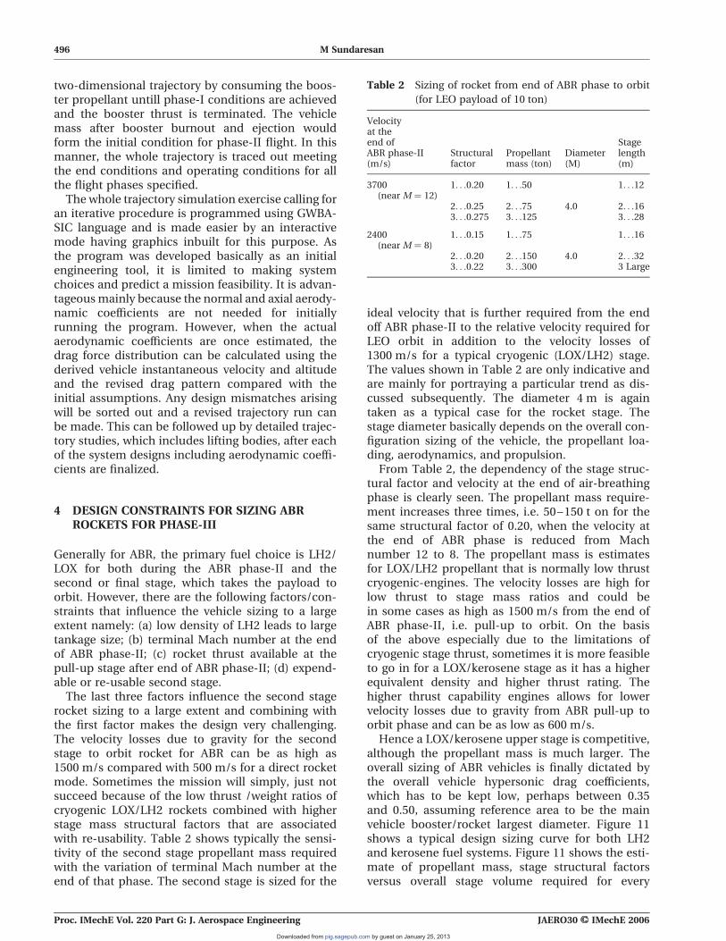
ideal velocity that is further required from the endoff ABR phase-II to the relative velocity required forLEO orbit in addition to the velocity losses of1300 m/s for a typical cryogenic (LOX/LH2) stage.The values shown in Table 2 are only indicative andare mainly for portraying a particular trend as dis-cussed subsequently. The diameter 4 m is againtaken as a typical case for the rocket stage. Thestage diameter basically depends on the overall con-figuration sizing of the vehicle, the propellant loa-ding, aerodynamics, and propulsion.
From Table 2, the dependency of the stage struc-tural factor and velocity at the end of air-breathingphase is clearly seen. The propellant mass require-ment increases three times, i.e. 50–150 t on for thesame structural factor of 0.20, when the velocity atthe end of ABR phase is reduced from Machnumber 12 to 8. The propellant mass is estimatesfor LOX/LH2 propellant that is normally low thrustcryogenic-engines. The velocity losses are high forlow thrust to stage mass ratios and could bein some cases as high as 1500 m/s from the end ofABR phase-II, i.e. pull-up to orbit. On the basisof the above especially due to the limitations ofcryogenic stage thrust, sometimes it is more feasibleto go in for a LOX/kerosene stage as it has a higherequivalent density and higher thrust rating. Thehigher thrust capability engines allows for lowervelocity losses due to gravity from ABR pull-up toorbit phase and can be as low as 600 m/s.
Hence a LOX/kerosene upper stage is competitive,although the propellant mass is much larger. Theoverall sizing of ABR vehicles is finally dictated bythe overall vehicle hypersonic drag coefficients,which has to be kept low, perhaps between 0.35and 0.50, assuming reference area to be the mainvehicle booster/rocket largest diameter. Figure 11shows a typical design sizing curve for both LH2and kerosene fuel systems. Figure 11 shows the esti-mate of propellant mass, stage structural factorsversus overall stage volume required for every
Table 2 Sizing of rocket from end of ABR phase to orbit
(for LEO payload of 10 ton)
Velocityat theend ofABR phase-II(m/s)
Structuralfactor
Propellantmass (ton)
Diameter(M)
Stagelength(m)
3700(near M ¼ 12)
1. . .0.20 1. . .50 1. . .12
2. . .0.25 2. . .75 4.0 2. . .163. . .0.275 3. . .125 3. . .28
2400(near M ¼ 8)
1. . .0.15 1. . .75 1. . .16
2. . .0.20 2. . .150 4.0 2. . .323. . .0.22 3. . .300 3 Large
496 M Sundaresan
Proc. IMechE Vol. 220 Part G: J. Aerospace Engineering JAERO30 # IMechE 2006
by guest on January 25, 2013pig.sagepub.comDownloaded from

tonne of LEO payload from the end of ABR phase-II,i.e. Mach number 12 to LEO orbit. It is seen that as anexample from Fig. 11; for a 30 m3 stage volume, thepropellant mass for a cryogenic propellant wouldbe around 10 ton, whereas it can accommodate30 ton of LOX/kerosene semi-cryogenic propellantsystem. However, the above propellant masses arevalid when the stage structural factors are 0.25 and0.21 for cryogenic and semi-cryogenic systems,respectively. It is also seen that for a lower stagestructural factor of 0.20, both the structural factorcurves have a common point a favourable case forsemi-cryogenic systems. Figure 11 helps to clearlyknow beforehand what thrust rating would berequired to minimize the velocity losses due to lowthrust. Similar such graphs can be drawn for varioussizing velocities including varying velocity losses andspecific impulse of the propellant. As ABR vehiclesare drag sensitive, the stage volume and hence diam-eter size selection are important aspects.
5 CONCLUSIONS
A preliminary design approach is arrived at forsizing launch vehicles with rocket and air-breathingpropulsion. The ABR vehicle trajectory is separatedinto three flight phases, namely, the initial boosteror ascent phase, the air-breathing cruise phasefrom the desired Mach number to a maximum ofMach number 12, and lastly the pull-up to orbitphase for optimum vehicle sizing. An attempt hasbeen made to bring in the various design sensi-tivities and their effects on vehicle sizing. A newconcept of including the drag and thrust lossesconsidering their nature of distribution as equiva-lent Isp losses for estimating the vehicle instan-taneous velocity was suggested for rocket in theatmospheric region and for phase-I flight in thecase of ABR vehicles. The intermediary flight
phase-II for ABR vehicles could be independentlydesigned meeting the end conditions of phase-Iand also to deliver the appropriate velocity at thebeginning of phase-III flight. A simplistic two-dimensional trajectory simulation program withgraphical interaction has been developed, whichconsiders the velocity losses due to drag, gravity,and propulsion. The program helps in sizing thelaunch vehicle and for evaluating the variousstage modules that will give the desired velocitiesat the end of each flight phase satisfying the overallvehicle design requirements.
ACKNOWLEDGEMENTS
The author wishes to thank the chief editor and edi-torial staff of this journal for their painstaking effortsto make a publication possible while meeting thehigh standards of publication. The electronic systemof paper submission is very user friendly and amazing.Finally, the author would also like to thank thereviewers of the paper who also have put in lot ofeffort and taken tremendous responsibility for ensu-ring excellence. It would be the author’s endeavourto encourage the future young generation on the les-sons learnt.
REFERENCES
1 Ryan, R. S. and Townsend, J. S. Fundamentals andissues in launch vehicle design. J. Spacecraft Rocket,1997, 34(2), 192–198.
2 Rahn, M., Schottle, U. M., andMesserschmid, E. Impactof mission requirements and constraints on conceptuallaunch vehicle design. AIAA Paper 98-1554, April 1998.
3 Olds, J. R. Results of a rocket-based combined-cycle SSTOdesign using parametric MDO methods. SAE technicalpaper series, 941165; presented at Aerospace AtlanticConference, OH, 18–22 April, 1994.
4 Batts, G. W. and Pearson, S. D. Natural environmentrequirements definition for aerospace launch vehicledesign. AIAA paper 1996-397, Aerospace SciencesMeeting and Exhibit, 5–18 January 1996, 34th, Reno, NV.
5 Smith, O. E. and Adelfang, S. I. Atmospheric DensityModels for Launch Vehicle Design (DispersedAtmospheric Models 0–25 km altitudes, KSC). AIAAPaper 95-0057, AIAA, Aerospace Sciences Meeting andExhibit, 33rd, Reno, NV, 9–12 January 1995.
6 Sundaresan, M., Ramani, K., and GeethaiKrishnan, C.A comparative study on the existing launch vehicles per-formance with specific reference to vehicle Q-alpha distri-bution. Internal report no. VSSC:LVDG:TM:2:95, January1995.
7 Sundaresan, M. An overview of an air-breathing vehiclewith reference to some of the critical performanceparameters. International Study report, Head, VehicleConfiguration division, ILVP, VSSC, December 1995.
Fig. 11 Upper stage sizing from end of ABR phase to
LEO orbit
Design aspects of launch vehicle sizing 497
JAERO30 # IMechE 2006 Proc. IMechE Vol. 220 Part G: J. Aerospace Engineering
by guest on January 25, 2013pig.sagepub.comDownloaded from

APPENDIX
Notation
CD overall vehicle drag coefficient(reference area: with booster/stagediameter)
D drag force (kN), diameter (m)g gravitational constant (9.807 m/s2)Isp vacuum specific impulse (s)Ispi vacuum specific impulse of the ith
stage (s)/burnout altitude specificimpulse
IspABR Isp of air-breathing rocket during cruisephase (s)
M mach numberMVt mass of vehicle at any flight instant
(ton)n number of stagest time of flight instant (s)TABR thrust generated by ABR in the air-
breathing or cruise regime (kN)TBO time at booster burnout (s)
Teff effective thrust generated at any instant(kN)
VI vehicle ideal velocity (m/s)Vt vehicle velocity at any flight instant (m/s)VORB.VEL orbital velocity as required by missionVLOSSES velocity losses (m/s)VE.ROT earth rotational velocityWFi final mass of the stage at the ith stage/
event burn outWi initial mass of vehicle at ith stage/event
ignitionWpi propellant mass of the ith stageWpCt propellant mass flow rate consumed at
any instant (ton/s)WPAYL payload massWo overall vehicle massWTi total mass of the ith stagea angle of attack in degreesb flight path angle in degreessi stage structural factor of the ith stagescryo cryogenic stage structural factorsSC semi-cryogenic stage structural factori subscript
498 M Sundaresan
Proc. IMechE Vol. 220 Part G: J. Aerospace Engineering JAERO30 # IMechE 2006
by guest on January 25, 2013pig.sagepub.comDownloaded from