Design and Validation of a Compressor for a New Generation ...
11
1 Copyright © 2007 by Siemens DESIGN AND VALIDATION OF A COMPRESSOR FOR A NEW GENERATION OF HEAVY-DUTY GAS TURBINES F. Eulitz, B. Kuesters, F. Mildner, M. Mittelbach, A. Peters, B. van den Toorn, U. Waltke P. Rimmington, D. Wasdell Siemens AG Power Generation Muelheim/Ruhr Germany Siemens Power Generation Inc. Orlando USA ABSTRACT Siemens H-Class. Siemens has developed the world-largest H-class Gas Turbine (SGT TM ) that sets unparalleled standards for high efficiency, low life cycle costs and operating flexibility. With a power output of 340+ MW, the SGT5- 8000H gas turbine will be the primary driver of the new Siemens Combined Cycle Power Plant (SCC TM ) for the 50 Hz market, the SCC5-8000H, with an output of 530+ MW at more than 60% efficiency. After extensive lab and component testing, the prototype has been shipped to the power plant for an 18-month validation phase. In this paper, the compressor technology, which was developed for the Siemens H-class, is presented through its development and validation phases. Reliability and Availability. The compressor has been extensively validated in the Siemens Berlin Test Facility during consecutive engine test programs. All key parameters, such as mass flow, operating range, efficiency and aero mechanical behavior meet or exceed expectations. Six-sigma methodology has been exploited throughout the development to implement the technologies into a robust design. Efficiency. The new compressor technology applies the Siemens advanced aerodynamics design methodology based on the high performance airfoil (HPA) systematic which leads to broader operation range and higher efficiency than a standard controlled diffusion airfoil (CDA) design. Operational Flexibility. The compressor features an IGV and three rows of variable guide vanes for improved turndown capability and improved part load efficiency. Serviceability. The design has been optimized for serviceability and less complexity. Following the Siemens tradition, all compressor rotating blades can be replaced without rotor lift or destacking. Evolutionary Design Innovation. The compressor design incorporates the best features and experience from the operating fleets and technology innovation prepared through detailed research, analysis and lab testing in the past decade. The design tools are based on best practices from former Siemens KWU and Westinghouse with enhancements allowing for routine front-to-back compressor 3D CFD multistage analysis, unsteady blade row interaction, forced response analyses and aero-elastic analysis. Keywords: Siemens H-Class, Compressor Design, Compressor aerodynamics and mechanics, HPA Airfoils, Design Methods, Six-Sigma methodology, Testing, Validation 1 INTRODUCTION In response to the increasing worldwide need for reliable, lowest cost and environmentally compatible generation of energy, Siemens Power Generation has developed a new generation of H-class gas turbines with a power rated at 340+ MW and in combined-cycle 530+ MW with an efficiency of more than 60%. “In combined cycle operation, this turbine […] produces enough power to meet the needs of a city the size of Hamburg with 620,000 three-person households. By increasing the efficiency, 40,000 fewer tons of CO 2 are emitted annually compared to today’s best combined cycle power plants [6]“. The Siemens H-class system SGT5-8000H is the result of an intensive R&D program launched after the merger of Siemens KWU and Westinghouse aiming to combine the best features of both companies’ existing product lines with advanced technologies, see Figure 1. Proceedings of POWER2007 ASME Power 2007 July 17-19, 2007, San Antonio, Texas POWER2007-22100 Downloaded From: https://proceedings.asmedigitalcollection.asme.org on 06/30/2019 Terms of Use: http://www.asme.org/about-asme/terms-of-use
-
Upload
khangminh22 -
Category
Documents
-
view
2 -
download
0
Transcript of Design and Validation of a Compressor for a New Generation ...

Downloa
DESIGN AND VALIDATION OF A COMPRESSOR FOR A NEW GENERATION OF HEAVY-DUTY GAS TURBINES
F. Eulitz, B. Kuesters, F. Mildner, M. Mittelbach, A. Peters, B. van den Toorn, U. Waltke
P. Rimmington, D. Wasdell
Siemens AG Power Generation Muelheim/Ruhr
Germany
Siemens Power Generation Inc. Orlando
USA
Proceedings of POWER2007 ASME Power 2007
July 17-19, 2007, San Antonio, Texas
POWER2007-22100
ABSTRACT
Siemens H-Class. Siemens has developed the world-largest H-class Gas Turbine (SGTTM) that sets unparalleled standards for high efficiency, low life cycle costs and operating flexibility. With a power output of 340+ MW, the SGT5-8000H gas turbine will be the primary driver of the new Siemens Combined Cycle Power Plant (SCCTM) for the 50 Hz market, the SCC5-8000H, with an output of 530+ MW at more than 60% efficiency. After extensive lab and component testing, the prototype has been shipped to the power plant for an 18-month validation phase.
In this paper, the compressor technology, which was developed for the Siemens H-class, is presented through its development and validation phases.
Reliability and Availability. The compressor has been extensively validated in the Siemens Berlin Test Facility during consecutive engine test programs. All key parameters, such as mass flow, operating range, efficiency and aero mechanical behavior meet or exceed expectations. Six-sigma methodology has been exploited throughout the development to implement the technologies into a robust design.
Efficiency. The new compressor technology applies the Siemens advanced aerodynamics design methodology based on the high performance airfoil (HPA) systematic which leads to broader operation range and higher efficiency than a standard controlled diffusion airfoil (CDA) design.
Operational Flexibility. The compressor features an IGV and three rows of variable guide vanes for improved turndown capability and improved part load efficiency.
Serviceability. The design has been optimized for serviceability and less complexity. Following the Siemens tradition, all compressor rotating blades can be replaced without rotor lift or destacking.
ded From: https://proceedings.asmedigitalcollection.asme.org on 06/30/2019 Terms of Use
Evolutionary Design Innovation. The compressor design
incorporates the best features and experience from the operating fleets and technology innovation prepared through detailed research, analysis and lab testing in the past decade. The design tools are based on best practices from former Siemens KWU and Westinghouse with enhancements allowing for routine front-to-back compressor 3D CFD multistage analysis, unsteady blade row interaction, forced response analyses and aero-elastic analysis.
Keywords: Siemens H-Class, Compressor Design, Compressor aerodynamics and mechanics, HPA Airfoils, Design Methods, Six-Sigma methodology, Testing, Validation
1 INTRODUCTION In response to the increasing worldwide need for reliable,
lowest cost and environmentally compatible generation of energy, Siemens Power Generation has developed a new generation of H-class gas turbines with a power rated at 340+ MW and in combined-cycle 530+ MW with an efficiency of more than 60%. “In combined cycle operation, this turbine […] produces enough power to meet the needs of a city the size of Hamburg with 620,000 three-person households. By increasing the efficiency, 40,000 fewer tons of CO2 are emitted annually compared to today’s best combined cycle power plants [6]“.
The Siemens H-class system SGT5-8000H is the result of an intensive R&D program launched after the merger of Siemens KWU and Westinghouse aiming to combine the best features of both companies’ existing product lines with advanced technologies, see Figure 1.
1 Copyright © 2007 by Siemens
: http://www.asme.org/about-asme/terms-of-use

Down
Figure 1: The new Siemens 340+ MW SGT5-8000H gas turbine.
Figure 2: Expected startup times for an exclusively air-cooled gas turbine compared to a steam-cooled H-class system.
Following a comprehensive feasibility analysis during the conceptual design phase a fully-air-cooled concept was chosen out of four thermodynamic cycle designs and 20 variants of engines investigated. Increased operational flexibility, high efficiency, reliability and availability and low-life-cycle costs were the key drivers for shaping the concept of the new H-class Siemens gas turbine and choosing among proven design features and advanced technologies:
• Compressor technology as detailed in chapter 2 • Low emission ULN combustion system • Advanced materials to increase the firing and exhaust
temperature • Advanced sealing system for reduced cooling air
leakage • Single tie-bolt rotor with hydraulic clearance
optimization • Turndown capability (50%) for high efficiency and low
emission part load operation • Direct scaling e.g. for 60 Hz applications possible
The nominal mass flow of the world’s largest gas turbine,
loaded From: https://proceedings.asmedigitalcollection.asme.org on 06/30/2019 Terms of Use:
Figure 3: The SGT5-8000H gas turbine in final assembly.
weighing 440 metric tons and measuring 13m long by 5m high, is rated at 800 kg/s at ISO conditions (see Figure 3).
The SCC-8000H combined cycle power plant will be equipped with proven technologies and components featuring a single-shaft arrangement and including a once-through BENSON® boiler technology, a Siemens SST5-5000 steam turbine and a Siemens SGen5-3000W water-cooled generator. The combined cycle process is optimized for a high pressure (170 bar) and high temperature (600 deg C), based on the high mass flow and exhaust temperature of the new gas turbine. As is shown in Figure 2, with less complexity of the engine and plant leading to greater operational flexibility, the fully air cooled technology achieves a much quicker startup time than a steam-cooled system.
Repeated testing and comprehensive validation efforts have been one of the characteristic cornerstones of the SGT5-8000H development program. With the completion of a series of comprehensive subsystem test programs, most of the gas turbine major components - including the compressor as presented below - have already reached pre-validation status,
2 Copyright © 2007 by Siemens
http://www.asme.org/about-asme/terms-of-use

while further testing is in process. The validation efforts will culminate in an 18-month prototype validation test program in a real power plant in Germany under a hosting agreement with E.ON. The gas turbine has been shipped to the test site in spring 2007 and the power plant is in the final construction phase for a first fire by end of 2007.
Initiating a compressor development for H-class gas turbines at the beginning of the 21st century opens up opportunities for significant enhancements: there is the learning from the extensive experience gained from millions of operating hours of the existing gas turbine fleets as well as exploiting the progress in research in design methodologies, in compressor aerodynamics and structures and the significantly improved predictive capabilities of cutting edge high resolution CAE methods. In this report, the compressor design, its development and pre-validation for the new H-class is presented in detail.
NOMENCLATURE BTF Berlin Test Facility CAE Computer Aided Engineering CDA Controlled Diffusion Airfoil CFD Computational Fluid Dynamics CV Compressor Vane DOE Design of Experiments FEA Finite Element Analysis FMEA Failure Mode and Effects Analysis FOD Foreign Object Damage HPA High Performance Airfoil IGV Inlet Guide Vane PR Pressure Ratio SPGI Siemens Power Generation, Inc. ULN Ultra Low NOx VGV Variable Guide Vanes
2 COMPRESSOR DESIGN FEATURES The SGT5-8000H compressor has been designed with
an evolutionary technology innovation concept which can be characterized by repeated testing and validation, as is illustrated in Figure 4. At the outset of the new development, an initial compressor was designed as a technology demonstrator for the 60 Hz size in order to be able to prove the advancements of the new technologies and design solutions. It was then tested at full scale in the Berlin test facility (BTF). After successful testing under a wide range of operating conditions the design of the SGT5-8000H compressor was initiated using the rear stages of the technology demonstrator and modifying the front stages for the desired increase of mass flow and pressure ratio by utilizing the validated technologies, methods and design features by the established team. A 60 Hz scaled version of this compressor (scaling factor of 1:1.2) has been manufactured and successfully tested in 2006, again in the BTF. Both compressor tests
Downloaded From: https://proceedings.asmedigitalcollection.asme.org on 06/30/2019 Terms of Use
Figure 4: Evolutionary design innovation for the compressor of the Siemens H-class.
Figure 5: Compressor cross section of the Siemens SGT5-8000H gas turbine.
programs were run on the SGT6-5000F test facility engine under all possible operation conditions.
The SGT5-8000H 13-stage compressor, as shown in a cross section in Figure 5, is designed for a mass flow of 800kg/s at a pressure ratio of 19:1. The compressor features vane carriers from stage 6 onwards for the respective stage groups separated by the outer bleeds which is a proven design of the existing fleet. The use of the vane carriers along with the inner bleed has been exploited to enhance the thermal alignment of the rotor with the casings thus minimizing the hot running clearances and enhancing the efficiency of the compressor. The compressor has been equipped with multiple rows of variable guide vanes (VGV) to enhance the part load performance and operational flexibility, see also Figure 6 for a detail. The VGV, which are individually adjustable per row, are supported by inner rings.
3 Copyright © 2007 by Siemens
: http://www.asme.org/about-asme/terms-of-use

Down
Figure 6: In addition to the IGV the compressor is equipped with 3 additional rows of VGV for enhancement of part load performance.
Figure 7: Blade attachments of front stages (left) and rear stages (right).
The design of the VGV was derived from the experience of the existing fleet. For improved serviceability, the rotating blade designs have been realized to allow for their replacement without a rotor lift. The front stage blades feature an axial dovetail root based on the existing fleet design (see Figure 7 left). The rear stage blades (see Figure 7 right) feature T-root design which can be easily twisted into the disk groove with the rotor in place for assembly and disassembly. All rear stage vanes have H-shaped roots which are directly slid into the vane carriers, see Figure 8.
The blade and vane airfoil geometry has been optimized, particularly around the leading and trailing edges, to provide the maximum degree of insensitivity to FOD and erosion whilst retaining good efficiency [2]. The blades and vanes are of Siemens proven materials.
loaded From: https://proceedings.asmedigitalcollection.asme.org on 06/30/2019 Terms of U
Vane Carrier & Slide Around VaneVane Carrier & Slide Around Vane .
Figure 8: Cantilevered stators with H-shape roots.
3 DESIGN METHODOLOGIES The design went through the new Product
Development Process consisting of conceptual, basic, and final design phases as well as manufacturing, testing and field validation phases each with tollgate milestones for intensive design review and gate release processes. A core element of this process is continuous risk abatement including a series of failure mode and effects analyses (FMEA) for each design phase and subsequent risk mitigation steps. During the conceptual design phase, alternative design concepts were evaluated in detail and benchmarked against each other to assess their impact on component reliability, performance, and other design criteria. Six-Sigma methodologies were widely used to assess the impact of design variability and ensure robustness.
The design system is the result of a major R&D effort on best practice integration from the broad knowledge and experience base of the former separate organizations Siemens KWU and Westinghouse; with the integrated design system that was build after the merger in 1998 the foundation was laid for a global concurrent engineering development of the H-class sharing a common cutting edge design tool set. The integrated design system ranges from 1D to 3D design and analysis tools for mechanics and aerodynamics, including 3D CFD multistage full component analysis from front to back. Also, the design system allows for unsteady 3D CFD analysis of stage interaction far off-design as well as coupled fluid-structure interaction analyses. The design tools have been extensively verified and calibrated prior to the design through use of lab tests and measurement data from the existing fleets.
3.1 Aerodynamic Design The aerodynamic design applies results of intensive
research completed at Siemens in the past decade on advanced compressor aero design to optimize on efficiency and a wide operating range [3, 4, and 7]. This has led to a design with higher stage pressure ratios and thus a comparably low stage count which also allows for a compact build of the compressor and the engine.
4 Copyright © 2007 by Siemens
se: http://www.asme.org/about-asme/terms-of-use

Down
Figure 9: Aero design targeted for enhanced operation range.
State of the art numerical optimization algorithms were taken full advantage of in the present design. The coupling of a genetic optimization algorithm with an in-house mean-line code enabled the assessment and reduction of variability of main geometrical design parameters on critical aerodynamic design parameters like compressor efficiency and surge margin at design point and off-design conditions. The design parameters identified as having a strong impact on the objective function were varied using a DOE approach to generate a response surface of the objective function. To accomplish this, a 1D mean-line code was coupled with the proven state of the art Siemens 2D streamline curvature method [7]. The main components of the objective function to be optimized were mass flow and efficiency at design point conditions but also stability criteria at off-design conditions as shown in Figure 9. The acceptable limits of the geometrical parameters like thickness/chord, aspect ratio, pitch/chord or axial gap/pitch ratios were derived from existing fleet geometries and design experience. The optimum of the response surface defined the geometry of the final flow path. The process produced a load distribution over the compressor stages which served the design goals of a high base load performance in combination with a large off-design operating range. In subsequent steps the design was fine tuned accounting for aeromechanical constraints and feedback from multistage CFD calculations. Thus, the impact of hot running clearance changes on stage matching, efficiency, and surge margin was exploited.
Advanced 3D end wall design features, as displayed in Figure 10, have been applied to arrive at highly efficient transonic flow front stages. For the subsonic stages, compressor technology applies the HPA systematic which has been developed and validated over the past decade [3, 4].
Corrected Massflow
Pres
sure
Rat
io
Main Criteria:
Massflow
Efficiency
Main Criteria:
Stability
Operating Line
Operating Line
Surge Line
Surge Line
Reduced grid frequency / Increased ambient temperatures
SpeedLines
SpeedLines
Corrected speed = N * √ (TISO / T)
loaded From: https://proceedings.asmedigitalcollection.asme.org on 06/30/2019 Terms of Us
flow separation
c
Figure 10: Aero design optimization steps of a transoniairfoil by applying 3D end wall design features.
Loss
coef
ficie
nt
Incidence AngleAxial Airfoil Lenght
Isen
trop
icM
ach
Num
ber
Measurement
Loss
coef
ficie
nt
Incidence AngleAxial Airfoil Lenght
Isen
trop
icM
ach
Num
ber
Measurement
Figure 11: Comparison of HPA vs. CDA airfoil designs.
he HPA leads to optimized controlled diffusion airfoils at high
TReynolds number flows with a broader operating range than standard CDA designs as illustrated in Figure 11. The superior behavior of the HPA allows for higher stage pressure ratios when compared to CDA. The detailed aeromechanical design of individual airfoils was accompanied by numerous steady-state multistage analyses both at design and off-design conditions to check the impact of detailed design changes on adjacent blade rows. The quality of the 2D and 3D CFD results were checked by comparison with measurement results from compressors previously tested at the BTF. An example is given in Figure 12 showing the validation of a full compressor front to back CFD multistage analysis for a configuration from the existing fleet.
zone
Mach nocontours
flow separationzone
Mach nocontours
5 Copyright © 2007 by Siemens
e: http://www.asme.org/about-asme/terms-of-use
Downloa
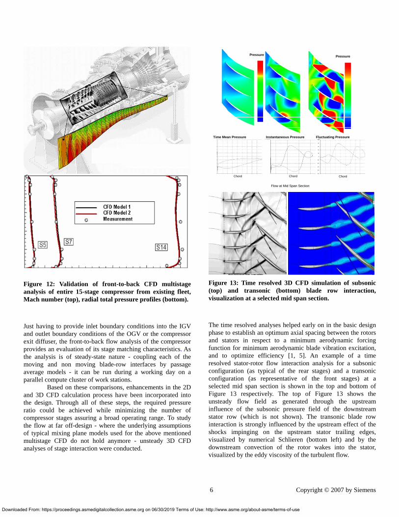
Figure 12: Validation of front-to-back CFD multistage analysis of entire 15-stage compressor from existing fleet, Mach number (top), radial total pressure profiles (bottom).
Just having to provide inlet boundary conditions into the IGV and outlet boundary conditions of the OGV or the compressor exit diffuser, the front-to-back flow analysis of the compressor provides an evaluation of its stage matching characteristics. As the analysis is of steady-state nature - coupling each of the moving and non moving blade-row interfaces by passage average models - it can be run during a working day on a parallel compute cluster of work stations.
Based on these comparisons, enhancements in the 2D and 3D CFD calculation process have been incorporated into the design. Through all of these steps, the required pressure ratio could be achieved while minimizing the number of compressor stages assuring a broad operating range. To study the flow at far off-design - where the underlying assumptions of typical mixing plane models used for the above mentioned multistage CFD do not hold anymore - unsteady 3D CFD analyses of stage interaction were conducted.
ded From: https://proceedings.asmedigitalcollection.asme.org on 06/30/2019 Terms of Use
Chord Chord Chord
Time Mean Pressure Instantaneous Pressure Fluctuating Pressure
Pressure Pressure
Flow at Mid Span Section
Chord Chord Chord
Time Mean Pressure Instantaneous Pressure Fluctuating Pressure
Pressure Pressure
Flow at Mid Span Section
Figure 13: Time resolved 3D CFD simulation of subsonic (top) and transonic (bottom) blade row interaction, visualization at a selected mid span section.
The time resolved analyses helped early on in the basic design phase to establish an optimum axial spacing between the rotors and stators in respect to a minimum aerodynamic forcing function for minimum aerodynamic blade vibration excitation, and to optimize efficiency [1, 5]. An example of a time resolved stator-rotor flow interaction analysis for a subsonic configuration (as typical of the rear stages) and a transonic configuration (as representative of the front stages) at a selected mid span section is shown in the top and bottom of Figure 13 respectively. The top of Figure 13 shows the unsteady flow field as generated through the upstream influence of the subsonic pressure field of the downstream stator row (which is not shown). The transonic blade row interaction is strongly influenced by the upstream effect of the shocks impinging on the upstream stator trailing edges, visualized by numerical Schlieren (bottom left) and by the downstream convection of the rotor wakes into the stator, visualized by the eddy viscosity of the turbulent flow.
6 Copyright © 2007 by Siemens
: http://www.asme.org/about-asme/terms-of-use

Dow
3.2 Mechanical Design Methodology Each aerodynamic design iteration has been
accompanied by an assessment of the mechanical integrity of the blades or vanes. 1D and 3D FEA with different level of detail were performed within the integrated design process. Initial iterations were typically performed on the hot, untwisted geometry. Final iterations of the cold, twisted product definition have been used to verify that the optimum aerodynamic design of the blades and vanes is achieved under engine operating conditions, that is, taking into account the thermal, centrifugal and gas loading.
All airfoils have been tuned to avoid unacceptable resonances in the operating range. A bladed disk sector model with contact and different nodal diameters has been applied to simulate engine conditions and accurately predict higher order modes. High cycle fatigue criteria have been applied to size the blading particularly for resonance crossings during startup. Other criteria helped to design for FOD, self induced vibration (flutter) or wear. The impact of variability was assessed and reduced through wide use of Six-Sigma methodology throughout the development and validation process. Fillet sizes were varied as well as the impact of airfoil tolerances and statistical variations were evaluated.
4 TESTING AND VALIDATION After completion of the design, the compressor component has been extensively validated through subsequent test programs in the Berlin Manufacturing Plant full power Test Facility (BTF) in 2005 and 2006. This test facility has been the backbone for the Siemens gas turbine development for more than 30 years. With its extensive infrastructure the facility offers full engine tests under any possible operation and load conditions using cutting edge, partly in-house developed, measurement and diagnostics technologies. Instead of converting the power into electricity, the test engine is working against a 6-disk water-break, which is the largest in the world of its kind. Load tests can, thus, be operated at different mechanical speeds allowing investigation of extreme under- and over-frequency behavior. The compressor tests have been run with a 60 Hz SGT6-5000F engine as a testing vehicle, as displayed in Figure 14. Special action was taken to ensure that the large H-class compressor could be tested over the operation range typical and beyond that of a SCC5-8000H power plant. Both testing programs have been conducted with a comprehensive instrumentation list including roughly 800 sensors for the detailed characterization
nloaded From: https://proceedings.asmedigitalcollection.asme.org on 06/30/2019 Terms of Us
Figure 14: View of the compressor during full scale engine tests in the Berlin Test Facility.
Figure 15: Front stage blades instrumented with strain gages.
of the compressors. The instrumentation consisted of 210 thermocouples, 330 pressures (static, dynamic or total) and 260 strain gages (rotating and stationary). All the compressor stages were equipped with strain gages on selected airfoils; see Figure 15 for instrumentation examples of the first three blade rows. Tip timing instrumentation, with optical and eddy current probes have been extensively applied to screen vibratory responses of all the blades of a wheel and investigate for any mistuning effects. In addition, hot running blade clearances were measured with capacitive tip clearance probes. Furthermore, instrumentation was added to accurately measure the angle position of the IGV and VGV and their actuation forces. As indicated above, the tests were conducted for a wider range of operation modes than is possible in a power plant connected to a grid with the benefit to gather detailed information about performance and full load points in under-frequency and over-frequency operation, hot restart tests and for VGV schedule optimization.
7 Copyright © 2007 by Siemens
e: http://www.asme.org/about-asme/terms-of-use

Dow
4.1 Aerodynamic Validation The compressor aerodynamics test results were found
to be well matched with design predictions from 2D and 3D CFD as shown in the pressure buildup through the compressor in Figure 16. Radial total temperature and pressure distribution were compared to design predictions at multiple operating conditions using Kiel head instrumentation and radial traverse 5-hole probes at various stages inside the compressor.
Figure 17 provides for a comparison of the predicted and measured radial profile at the leading edge of vane row 13.
The starting of the compressor for operation went smoothly without any issues and the design mass flow and pressure ratio were achieved in the very first attempt. The pressure fluctuations during startup in the front stages of the compressor were measured with fast response pressure transducers (“Kulites”) in order to investigate the onset and development of rotating instabilities during acceleration. The starting behavior of the compressor has been thoroughly explored with multiple variations of VGV setting and numbers of variable stages employed along with variations in handling blow-off flow. It can be concluded that no major issues were identified regarding the strength and pattern of rotating stall during acceleration, the blades and vanes responses were well below established criteria.
Axial Length
Sta
tic P
ress
ure 3D CFD
Test data
Figure 16: Example of validated pressure buildup through the compressor.
nloaded From: https://proceedings.asmedigitalcollection.asme.org on 06/30/2019 Terms of U
As confirmed by blow-off flow reduction the compressor has margin against engine to engine variation of the blow-off flow.
Six-Sigma methods were used to optimize the multiple stages of variable geometry to achieve the highest flow/efficiency combination at the base load condition and the highest efficiency at part load. For this, two DOE were accomplished to determine the optimum VGV setting angles and actuation rule. Clearance predictions were performed using a whole engine model. In order to evaluate the clearance calculations the model was calibrated through the comparison of metal temperatures at multiple instrumented locations to the measured values. Radial tip clearances were measured at multiple axial locations using capacitive clearance probes around the circumference at all relevant transient conditions. The goal of the campaign was the fine tuning of clearance prediction for the prototype build at the Irsching power plant.
Figure 17: Comparison between CFD prediction and test results at compressor vane 13.
8 Copyright © 2007 by Siemens
se: http://www.asme.org/about-asme/terms-of-use

Do
4.2 Structural Validation A comprehensive test program, including a large number
of startup variations as well as over- and under-frequency speed sweeps, has been performed to ensure the mechanical integrity under all operating conditions. Every row has been instrumented with strain gauges as well as tip timing instrumentation to monitor and analyze the vibration behavior online. Graphical visualization of vibration magnitude, envelope, i.e. a peak hold, and limits, spectral plots, i.e. Campbell Diagrams, as well as engine parameters or the vibratory response signature of all blades in a row helped to get a detailed understanding of every possible excitation and the vibratory characteristics, see Figure 18 for an example. The exploration of the starting behavior mentioned earlier in the framework of the conducted DOE’s helped to minimize blade vibration amplitudes particularly during a start.
Final validation of the mechanical design started initially with qualification of the manufacturing process applying ping testing and mode shape visualization via laser vibrometer techniques. As can be seen in Figure 19, the predicted mode shapes agree very well with the measurements even including the higher Eigen modes which are typically more prone to predictive uncertainties. Strain gage measurements of the Eigen frequencies taken during different operating conditions confirm this excellent predictive agreement. With such a good predictive capability - allowing for correct positioning of the strain gages - the vibration characteristics of higher modes could be investigated in detail.
Figure 18: Online monitoring of strain gage results.
wnloaded From: https://proceedings.asmedigitalcollection.asme.org on 06/30/2019 Terms of U
Being able to predict the vibration characteristics up to the high modes precisely on the one hand, and being able to detect the vibration behavior over a broad spectrum of Eigen frequencies on the other hand, has resulted in a validated mechanical design with proven small vibration amplitudes as shown for the stators in Figure 20. To ensure that this conclusion is valid for all blades independent of the selection of the specimen for strain gage instrumentation, blade tip timing was widely applied to investigate the vibration characteristics of entire blade rows, as shown in the example of Figure 21. The established tip-timing measurement methodology – calibrated by the testing programs in the Berlin Test Facility – will also be exploited for the characterization of the long term behavior of the compressor in the Irsching power plant, cf. to chapter 5. All blades and vane responses during both mentioned test programs did show sufficient margin for all operating conditions.
Figure 19: Comparison of predicted vibration mode shapes (top from FEM analysis) and measured mode shapes (bottom from vibrometer) validate design analysis.
9 Copyright © 2007 by Siemens
se: http://www.asme.org/about-asme/terms-of-use

Do
Figure 20: Measured maximum stress levels for all stators at steady-state operation from both testing programs versus a margined allowable.
5 VALIDATION IN PROTOTYPE PLANT Repeated testing and validation has been a key focus
during the development of the SGT5-8000H gas turbine. Similar to the compressor pre-validation, other key components have been submitted to extensive testing. For example, component testing programs were conducted or are in process at the following sites: ENEL (Italy) and DLR (Germany) for high pressure combustion; SPGI STC (Pittsburgh) for catalytic combustion, University of Central Florida, Florida Turbine Technology, Muelheim Factory Labs for aerodynamics and heat transfer; SPGI Casselberry Lab (Orlando) for atmospheric combustion ignition; Berlin Test Facility for compressor and combustion subsystem testing.
The extensive validation efforts will culminate in a detailed characterization phase of the new H-class Siemens gas turbine under real power plant conditions which will be carried out in Irsching, Germany under a hosting agreement with E.ON. For the validation scope, the plant will be built in a simple-cycle configuration. Nearly 3000 sensors have been installed to allow for a detailed characterization of the engine. After startup, part load and base load validation operation of the plant, a comprehensive endurance testing phase will be undertaken to demonstrate the system operation and reliability. With this extended testing phase, the overall validation program will take 18 months. As the gas turbine has been delivered to Irsching site in spring 2007 the plant is entering the final construction phase with a schedule moving on track for a first fire by late 2007. The completion of the validation phase is targeted for mid 2009. After the prototype tests, the simple-cycle test plant will be converted into a combined-cycle plant with optimized water-steam cycle components and ownership will be handed over to E.ON.
For the Irsching prototype, the compressor has been instrumented based on testing experience gained during the BTF test programs. With its successful pre-validation, the
wnloaded From: https://proceedings.asmedigitalcollection.asme.org on 06/30/2019 Terms of U
Figure 21: Example of a response signature during startup as a result of tip-timing measurements. primary scope of monitoring the compressor in the Irsching power plant is to support the system integration and durability testing.
SUMMARY Combining global knowledge, experience and proven
features from a large operating fleet with millions of operating hours and Siemens research results in gas turbine technologies and design tools, the world largest H-class gas turbine has been developed in a framework heavily focused on testing and pre-validation leading to a technology offering maximum efficiency at low life cycle costs and maximum operational flexibility. The paper presents the main features, development and testing activities of the compressor component of the new technology. The compressor consists of proven design features and new technologies to optimize H-class combined-cycle power generation: • Efficiency and operating range optimized through use of
Siemens developed HPA and advanced transonic aerodynamic design.
• Part-load efficiency optimized through use of 3 rows of VGV.
• Serviceability maximized through a design that allows for replacement of rotating blades without rotor lift.
• Robustness of design achieved through systematic feedback of fleet experience, use of proven design features such as FOD resisting design and balanced thermal behavior through vane carriers and the use of state of the art 3D design tools with advanced predictive capabilities and Six-Sigma methodologies.
The compressor has been successfully pre-validated in comprehensive full scale engine testing programs in the Berlin Test facility in 2005 and 2006 using some 800 sensors which have shown that the aerodynamic and mechanical characteristics meet or exceed design expectations. The next
10 Copyright © 2007 by Siemens
se: http://www.asme.org/about-asme/terms-of-use

Dow
and final step before commercialization will be to test the H-class gas turbine in a power plant in Irsching Unit 4 in an extensive testing program starting late 2007 and planned for completion by mid 2009. With the successful pre-validation the focus of the compressor characterization in Irsching will be on system integration and durability. The content of this paper is copyrighted by Siemens Power Generation, Inc. and is licensed to The American Society of Mechanical Engineers (ASME) for publication and distribution only. Any inquiries regarding permission to use the content of this paper, in whole or in part, for any purpose must be addressed to Siemens Power Generation, Inc. directly.
REFERENCES 1. Adamczyk, J.J., Strazisar, A.J., 1994, “Unsteady Flow in
Turbomachines – Where’s the beef?”, Unsteady Flow in Aeropropulsion, ASME Winter Annual Meeting, pp. 7-12.
2. Becker B., “Robust Gas Turbine Design”, ASME, GT-2002-30159.
3. Koeller, U., Moenig, R., Kuesters, B., Schreiber, H.-A., 1999, “Development of Advanced Compressor Airfoils for Heavy Duty Gas Turbines, Part I: Design and Optimization”, ASME, GT-1999-95
4. Kuesters, B., Schreiber, H.-A., Koeller, U., Moenig, R., 1999, “Development of Advanced Compressor Airfoils for Heavy Duty Gas Turbines, Part II: Experimental and Theoretical Analysis”, ASME, GT-1999-96
5. Montgomery M., Tartibi M., Schmitt S., Eulitz F., 2005, “Application of Unsteady Aerodynamics and Aeroelasticity in Heavy-Duty Gasturbines”, ASME, GT2005-68813.
6. Kleinfeld, K., Annual Shareholders' Meeting of Siemens AG on January 25, 2007. Report by President and CEO of Siemens AG Dr. Klaus Kleinfeld
7. Moenig, R., Mildner F., Roeper R., 2001, “Viscous-Flow Two-Dimensional Analysis Including Secondary Flow Effects”, Journal of Turbomachinery, ASME, July 2001
11 Copyright © 2007 by Siemens
nloaded From: https://proceedings.asmedigitalcollection.asme.org on 06/30/2019 Terms of Use: http://www.asme.org/about-asme/terms-of-use