
Design and Performance Analysis of Hybrid Battery ... - MDPI
14
sustainability Article Design and Performance Analysis of Hybrid Battery and Ultracapacitor Energy Storage System for Electrical Vehicle Active Power Management Aditya Kachhwaha 1 , Ghamgeen Izat Rashed 2, *, Akhil Ranjan Garg 1 , Om Prakash Mahela 3 , Baseem Khan 4 , Muhammed Badeaa Shafik 5 and Mohamed G. Hussien 6, * Citation: Kachhwaha, A.; Rashed, G.I.; Garg, A.R.; Mahela, O.P.; Khan, B.; Shafik, M.B.; Hussien, M.G. Design and Performance Analysis of Hybrid Battery and Ultracapacitor Energy Storage System for Electrical Vehicle Active Power Management. Sustainability 2022, 14, 776. https://doi.org/10.3390/su14020776 Academic Editors: Sanchari Deb and Nallapaneni Manoj Kumar Received: 13 September 2021 Accepted: 27 October 2021 Published: 11 January 2022 Publisher’s Note: MDPI stays neutral with regard to jurisdictional claims in published maps and institutional affil- iations. Copyright: © 2022 by the authors. Licensee MDPI, Basel, Switzerland. This article is an open access article distributed under the terms and conditions of the Creative Commons Attribution (CC BY) license (https:// creativecommons.org/licenses/by/ 4.0/). 1 Department of Electrical Engineering, Faculty of Engineering and Architecture, Jai Narain Vyas University, Jodhpur 342011, India; [email protected] (A.K.); [email protected] (A.R.G.) 2 School of Electrical Engineering and Automation, Wuhan University, Wuhan 430072, China 3 Assistant Engineer, Power System Planning Division, Rajasthan Rajya Vidyut Prasaran Nigam Ltd., Jaipur 302005, India; [email protected] 4 Department of Electrical and Computer Engineering, Hawassa University, Hawassa P.O. Box 5, Ethiopia; [email protected] 5 Electric Power System and Machines Department, Faculty of Engineering, Kafrelsheikh University, Kafrelsheikh 33516, Egypt; [email protected] 6 Department of Electrical Power and Machines Engineering, Faculty of Engineering, Tanta University, Tanta 31527, Egypt * Correspondence: [email protected] (G.I.R.); [email protected] (M.G.H.) Abstract: The electrical energy storage system faces numerous obstacles as green energy usage rises. The demand for electric vehicles (EVs) is growing in tandem with the technological advance of EV range on a single charge. To tackle the low-range EV problem, an effective electrical energy storage device is necessary. Traditionally, electric vehicles have been powered by a single source of power, which is insufficient to handle the EV’s dynamic demand. As a result, a unique storage medium is necessary to meet the EV load characteristics of high-energy density and high-power density. This EV storage system is made up of two complementing sources: chemical batteries and ultracapacitors/supercapacitors. The benefits of using ultracapacitors in a hybrid energy storage system (HESS) to meet the low-power electric car dynamic load are explored in this study. In this paper, a HESS technique for regulating the active power of low-powered EV simulations was tested in a MATLAB/Simulink environment with various dynamic loading situations. The feature of this design, as noted from the simulation results, is that it efficiently regulates the DC link voltage of an EV with a hybrid source while putting minimal load stress on the battery, resulting in longer battery life, lower costs, and increased vehicle range. Keywords: electric vehicles; battery; ultracapacitors; energy storage system 1. Introduction Electric cars (EVs) are becoming more popular as a result of environmental concerns and rising gasoline prices. When compared to gasoline-based internal combustion engine (ICE) vehicles, EVs have superior fuel economy and adhere to modern world pollution requirements. Standard EVs are available on the market as a power source. It is worth noting that EVs are subjected to a variety of time-varying power needs, such as abrupt acceleration and deceleration (regeneration period). This acceleration and regeneration period is analogous to pulse load changes, and the battery must absorb a huge transient charging current at this time, negatively impacting the battery’s performance. A supple- mentary energy storage technology (ultracapacitor) is occasionally used to mitigate this negative effect on the battery [1]. By incorporating diverse topologies of ultracapacitor connection, the influence of the battery’s performance on abrupt charging and draining can be mitigated. An ultracapacitor Sustainability 2022, 14, 776. https://doi.org/10.3390/su14020776 https://www.mdpi.com/journal/sustainability
-
Upload
khangminh22 -
Category
Documents
-
view
3 -
download
0
Transcript of Design and Performance Analysis of Hybrid Battery ... - MDPI

sustainability
Article
Design and Performance Analysis of Hybrid Battery andUltracapacitor Energy Storage System for Electrical VehicleActive Power Management
Aditya Kachhwaha 1, Ghamgeen Izat Rashed 2,*, Akhil Ranjan Garg 1 , Om Prakash Mahela 3 , Baseem Khan 4,Muhammed Badeaa Shafik 5 and Mohamed G. Hussien 6,*
�����������������
Citation: Kachhwaha, A.;
Rashed, G.I.; Garg, A.R.; Mahela, O.P.;
Khan, B.; Shafik, M.B.; Hussien, M.G.
Design and Performance Analysis of
Hybrid Battery and Ultracapacitor
Energy Storage System for Electrical
Vehicle Active Power Management.
Sustainability 2022, 14, 776.
https://doi.org/10.3390/su14020776
Academic Editors: Sanchari Deb and
Nallapaneni Manoj Kumar
Received: 13 September 2021
Accepted: 27 October 2021
Published: 11 January 2022
Publisher’s Note: MDPI stays neutral
with regard to jurisdictional claims in
published maps and institutional affil-
iations.
Copyright: © 2022 by the authors.
Licensee MDPI, Basel, Switzerland.
This article is an open access article
distributed under the terms and
conditions of the Creative Commons
Attribution (CC BY) license (https://
creativecommons.org/licenses/by/
4.0/).
1 Department of Electrical Engineering, Faculty of Engineering and Architecture, Jai Narain Vyas University,Jodhpur 342011, India; [email protected] (A.K.); [email protected] (A.R.G.)
2 School of Electrical Engineering and Automation, Wuhan University, Wuhan 430072, China3 Assistant Engineer, Power System Planning Division, Rajasthan Rajya Vidyut Prasaran Nigam Ltd.,
Jaipur 302005, India; [email protected] Department of Electrical and Computer Engineering, Hawassa University, Hawassa P.O. Box 5, Ethiopia;
[email protected] Electric Power System and Machines Department, Faculty of Engineering, Kafrelsheikh University,
Kafrelsheikh 33516, Egypt; [email protected] Department of Electrical Power and Machines Engineering, Faculty of Engineering, Tanta University,
Tanta 31527, Egypt* Correspondence: [email protected] (G.I.R.); [email protected] (M.G.H.)
Abstract: The electrical energy storage system faces numerous obstacles as green energy usage rises.The demand for electric vehicles (EVs) is growing in tandem with the technological advance ofEV range on a single charge. To tackle the low-range EV problem, an effective electrical energystorage device is necessary. Traditionally, electric vehicles have been powered by a single sourceof power, which is insufficient to handle the EV’s dynamic demand. As a result, a unique storagemedium is necessary to meet the EV load characteristics of high-energy density and high-powerdensity. This EV storage system is made up of two complementing sources: chemical batteries andultracapacitors/supercapacitors. The benefits of using ultracapacitors in a hybrid energy storagesystem (HESS) to meet the low-power electric car dynamic load are explored in this study. In thispaper, a HESS technique for regulating the active power of low-powered EV simulations was testedin a MATLAB/Simulink environment with various dynamic loading situations. The feature of thisdesign, as noted from the simulation results, is that it efficiently regulates the DC link voltage of anEV with a hybrid source while putting minimal load stress on the battery, resulting in longer batterylife, lower costs, and increased vehicle range.
Keywords: electric vehicles; battery; ultracapacitors; energy storage system
1. Introduction
Electric cars (EVs) are becoming more popular as a result of environmental concernsand rising gasoline prices. When compared to gasoline-based internal combustion engine(ICE) vehicles, EVs have superior fuel economy and adhere to modern world pollutionrequirements. Standard EVs are available on the market as a power source. It is worthnoting that EVs are subjected to a variety of time-varying power needs, such as abruptacceleration and deceleration (regeneration period). This acceleration and regenerationperiod is analogous to pulse load changes, and the battery must absorb a huge transientcharging current at this time, negatively impacting the battery’s performance. A supple-mentary energy storage technology (ultracapacitor) is occasionally used to mitigate thisnegative effect on the battery [1].
By incorporating diverse topologies of ultracapacitor connection, the influence of thebattery’s performance on abrupt charging and draining can be mitigated. An ultracapacitor
Sustainability 2022, 14, 776. https://doi.org/10.3390/su14020776 https://www.mdpi.com/journal/sustainability

Sustainability 2022, 14, 776 2 of 14
can handle an instantaneous impulse EV load since it is a high-power density device, whichdecreases the stress on the battery and raises the high-rate current demand. The combina-tion of a battery and an ultracapacitor allows us to meet peak power demand for a shortperiod of time with the ultracapacitor and average power demand for a long period oftime with the battery [2,3]. Ultracapacitors have the advantage of being able to deliverand even absorb huge transient pulse power, ensuring that the load’s requirements aremet during the drive’s abrupt acceleration and deceleration/regenerative periods. Becausethe battery and ultracapacitor have different basic characteristics (for example, voltagelevels or charging/discharging), an adequate interface between both sources is essential.Multiple types of energy storage, such as batteries and ultracapacitors, can improve theoverall performance of EVs by providing higher-power density, energy density, and lifecycle. In addition, the improved Hybrid Energy Storage System (HESS) between thesedevices will reduce energy utilization and extend battery life [4]. To meet the dynamicEV demand, our active HESS allows ultracapacitors and batteries to use their maximumcapacity [4,5]. An active HESS arrangement makes the most of the available ultracapaci-tors energy, resulting in enhanced fuel economy and energy security due to the usage ofvarious sources.
Charging, discharging, voltage level, and other basic features of the hybrid source(ultracapacitor and battery) are not equal, and a suitable interface is necessary. Because abidirectional DC-DC converter can meet the requirements for high utilization efficiencies,a real-time EV energy storage management strategy (known as HESS) is required for abetter and more effective allocation of power demand for the vehicular system betweenenergy storage devices [1,6]. Active power management always uses a single controlvariable and a single control state (source state-of-charge, source power level). As a result,adding an ultracapacitor to the system introduces another control variable with a stateof a degree of freedom. The design and optimization of active power management arecomplicated by this additional state [7].
This hybridization of battery and ultracapacitor protects the battery and also optimizesthe size of both energy storage systems using the different HESS management schemes,which further reduces the overall cost [8]. Many HESS management schemes, such as thefuzzy-logic control scheme [9], the rule-based control scheme [10], the model-predictivecontrol scheme [11], and the filtration-based scheme [12] etc., are introduced over time.Hung et al. [13] proposed an optimization scheme that involved the sizing of a hybridsource with an energy storage management strategy to achieve high performance of an EVwith minimum operating costs. Both the constraints of sizing and the power managementof an EV must be controlled simultaneously, as the individual system contains differentcomponents, which can be incorporated using a rule-based HESS technique [7,14].
The combined use of several energy storage systems in an EV allows the system toharness diverse sources at different times to efficiently drive the system [7,15]. On thebasis of diverse load profiles, such as constant frequency, variable frequency pulsing load,and the typical WLTC Class 1 (a small, low-powered EV) drive cycle, this research examinesthe performance of rule-based HESS active power-sharing amongst hybrid sources [16–26].The proposed HESS system is tested using this standard real drive, in conjunction withthe EV dynamic model, to generate a small-scale EV load profile. The system is thensubjected to the obtained load profile, and the simulation results are evaluated in theMATLAB/Simulink environment. Numerous variants of a rule-based active HESS schemewere used in this study, successfully reducing the constraint of a single power source(limited energy density and power density).
2. Proposed Electrical Vehicle Model
The key parameter of analysis is a rule-based active HESS, which subjects the systemto the real drive equivalent of instantaneous power demand. This can be obtained byimplementing the dynamic modeling approach, which is based on the power-torqueequation shown in Figure 1. The EV system dynamic input parameters are shown in Table 1.

Sustainability 2022, 14, 776 3 of 14
Acceleration force, aerodynamic drag force, rolling resistance force and gravitational forceare the main components. Their summation is known as the total traction force (FT),which is applied to the EV drive wheels that vary instantaneously, according to the drivecycle [7,15] (here, WLTC Class 1 is used [16]).
Sustainability 2021, 13, x FOR PEER REVIEW 3 of 14
2. Proposed Electrical Vehicle Model The key parameter of analysis is a rule-based active HESS, which subjects the system
to the real drive equivalent of instantaneous power demand. This can be obtained by im-plementing the dynamic modeling approach, which is based on the power-torque equa-tion shown in Figure 1. The EV system dynamic input parameters are shown in Table 1. Acceleration force, aerodynamic drag force, rolling resistance force and gravitational force are the main components. Their summation is known as the total traction force (FT), which is applied to the EV drive wheels that vary instantaneously, according to the drive cycle [7,15] (here, WLTC Class 1 is used [16]).
Table 1. Low-power small EV system dynamics.
EV Parameters Unit Value Total EV Weight 500–600 Kg Average Speed 25 Km/h
Max Speed 70 Km/h Aerodynamic Drag Coefficient 0.34
Rolling Coefficients 0.01–0.02 Electric Drive Power 48 Volt, 3–4 Kw
Figure 1. EV dynamic model block diagram.
The force corresponding to rolling friction resistance, which is caused by the action between EV wheels and a road surface, is represented by the following Equation (1). The rolling resistance force is directly proportional to the vehicle weight and, from Equation (1), C = rolling coefficient that presents the roughness factor of a surface. 𝑊 = Weight of EV. 𝐹 = 𝑊 × 𝐶 (1)
The grade resistance force is a type of gravitational force that acts in the opposite direction to the EV motion when running on an inclined surface. The grading resistance force of an EV during the drive cycle inclined motion can be obtained by Equation (2). The surface angle Ɵ has a high inclination here [27]. 𝐹 = 𝑊 × sin Ɵ (2)
The force related to the EV drive torque is directly related to the acceleration of the vehicle. The acceleration force forces the vehicle to reach its nominal speed within the time limit specified. The acceleration force is given by Equation (3). Here, a denotes acceleration and m denotes the EV’s mass [7].
Figure 1. EV dynamic model block diagram.
Table 1. Low-power small EV system dynamics.
EV Parameters Unit Value
Total EV Weight 500–600 Kg
Average Speed 25 Km/h
Max Speed 70 Km/h
Aerodynamic Drag Coefficient 0.34
Rolling Coefficients 0.01–0.02
Electric Drive Power 48 Volt, 3–4 Kw
The force corresponding to rolling friction resistance, which is caused by the action be-tween EV wheels and a road surface, is represented by the following Equation (1). The rollingresistance force is directly proportional to the vehicle weight and, from Equation (1),CR = rolling coefficient that presents the roughness factor of a surface. WEV = Weightof EV.
FRolling = WEV × CR (1)
The grade resistance force is a type of gravitational force that acts in the oppositedirection to the EV motion when running on an inclined surface. The grading resistanceforce of an EV during the drive cycle inclined motion can be obtained by Equation (2).The surface angle θ has a high inclination here [27].
FGRF = WEV × sin θ (2)
The force related to the EV drive torque is directly related to the acceleration of thevehicle. The acceleration force forces the vehicle to reach its nominal speed within the timelimit specified. The acceleration force is given by Equation (3). Here, a denotes accelerationand m denotes the EV’s mass [7].
Fa = m × a (3)

Sustainability 2022, 14, 776 4 of 14
The aerodynamic drag phenomenon increases resistance during a higher speed ofan EV, represented as vehicle speed function in Equation (4). Here v = EV speed, p = airdensity, CD = drag coefficient and AreaF = vehicle frontal area.
FADR =12× p × v2 × CD × AreaF (4)
The total EV tractive force can be obtained by Equations (1)–(4), as shown in Equa-tion (5). It is the summation of all kinds of forces acting on the EV during the drive cyclerun [27].
FT = FRolling + FGRF + Fa + FADR (5)
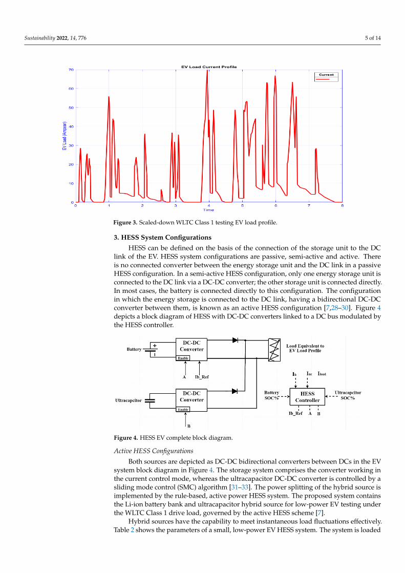
The standard WLTC Class 1 city drive cycle for low-power EVs is shown in Figure 2.This drive cycle with the vehicle dynamic model is used to obtain the total instantaneouspower required for the EV wheels. The all-corresponding vehicle dynamic model wave-forms are shown in Figure 2. The total EV dynamic load is calculated by the EV dynamicmodel, as shown in Figure 3; it is scaled-down to test the load current profile of a WLTCClass 1 with an active power HESS scheme [7,27].
Sustainability 2021, 13, x FOR PEER REVIEW 4 of 14
𝐹 = 𝑚 × 𝑎 (3)
The aerodynamic drag phenomenon increases resistance during a higher speed of an EV, represented as vehicle speed function in Equation (4). Here 𝑣 = EV speed, 𝑝 = air density, 𝐶 = drag coefficient and 𝐴𝑟𝑒𝑎 = vehicle frontal area. 𝐹 = 12 × 𝑝 × 𝑣 × 𝐶 × 𝐴𝑟𝑒𝑎 (4)
The total EV tractive force can be obtained by Equations (1)–(4), as shown in Equation (5). It is the summation of all kinds of forces acting on the EV during the drive cycle run [27]. 𝐹 = 𝐹 𝐹 𝐹 𝐹 (5)
The standard WLTC Class 1 city drive cycle for low-power EVs is shown in Figure 2. This drive cycle with the vehicle dynamic model is used to obtain the total instantaneous power required for the EV wheels. The all-corresponding vehicle dynamic model wave-forms are shown in Figure 2. The total EV dynamic load is calculated by the EV dynamic model, as shown in Figure 3; it is scaled-down to test the load current profile of a WLTC Class 1 with an active power HESS scheme [7,27].
Figure 2. EV dynamic modeling under a WLTC Class 1 drive cycle. Figure 2. EV dynamic modeling under a WLTC Class 1 drive cycle.
Sustainability 2022, 14, 776 5 of 14Sustainability 2021, 13, x FOR PEER REVIEW 5 of 14
Figure 3. Scaled-down WLTC Class 1 testing EV load profile.
3. HESS System Configurations HESS can be defined on the basis of the connection of the storage unit to the DC link
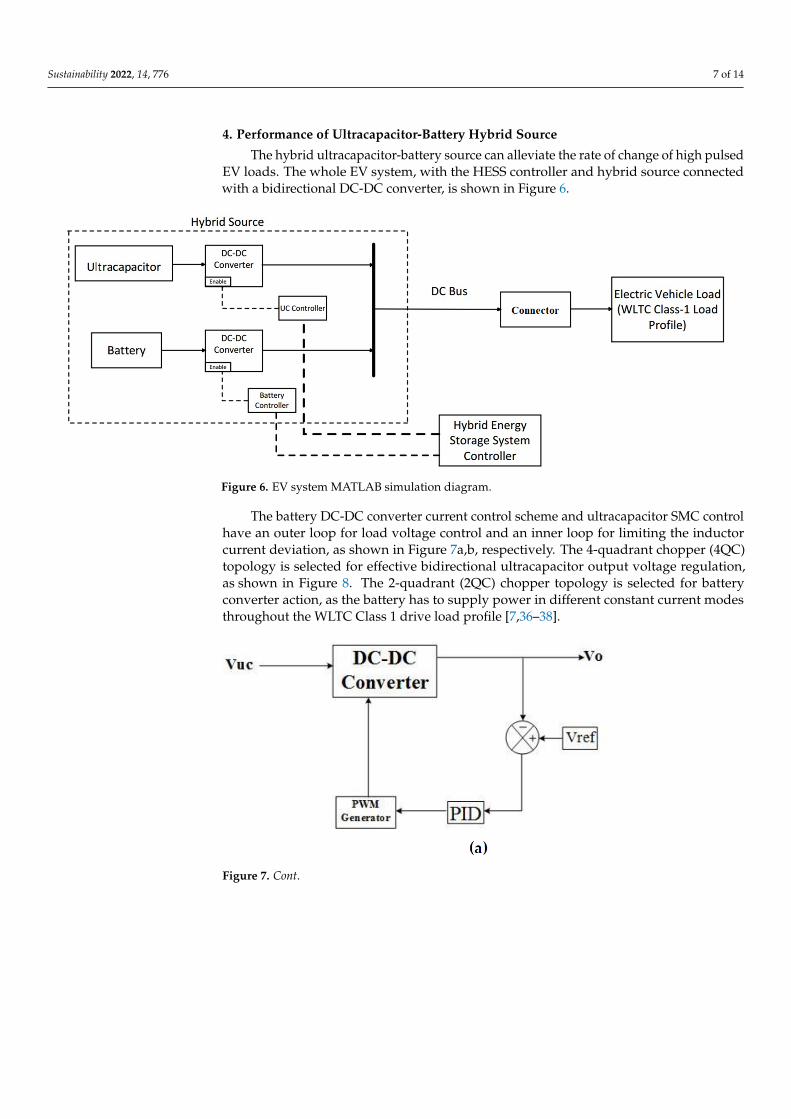
of the EV. HESS system configurations are passive, semi-active and active. There is no connected converter between the energy storage unit and the DC link in a passive HESS configuration. In a semi-active HESS configuration, only one energy storage unit is con-nected to the DC link via a DC-DC converter; the other storage unit is connected directly. In most cases, the battery is connected directly to this configuration. The configuration in which the energy storage is connected to the DC link, having a bidirectional DC-DC con-verter between them, is known as an active HESS configuration [7,28–30]. Figure 4 depicts a block diagram of HESS with DC-DC converters linked to a DC bus modulated by the HESS controller.
Active HESS Configurations Both sources are depicted as DC-DC bidirectional converters between DCs in the EV
system block diagram in Figure 4. The storage system comprises the converter working in the current control mode, whereas the ultracapacitor DC-DC converter is controlled by a sliding mode control (SMC) algorithm [31–33]. The power splitting of the hybrid source is implemented by the rule-based, active power HESS system. The proposed system con-tains the Li-ion battery bank and ultracapacitor hybrid source for low-power EV testing under the WLTC Class 1 drive load, governed by the active HESS scheme [7].
Hybrid sources have the capability to meet instantaneous load fluctuations effec-tively. Table 2 shows the parameters of a small, low-power EV HESS system. The system is loaded with the WLTC Class 1 current load profile, calculated by the vehicle dynamic model. Alongside this, the EV HESS system is subjected to a constant and varying fre-quency pulse load. The active HESS controller scheme is represented in Figure 5.
Figure 3. Scaled-down WLTC Class 1 testing EV load profile.
3. HESS System Configurations
HESS can be defined on the basis of the connection of the storage unit to the DClink of the EV. HESS system configurations are passive, semi-active and active. Thereis no connected converter between the energy storage unit and the DC link in a passiveHESS configuration. In a semi-active HESS configuration, only one energy storage unit isconnected to the DC link via a DC-DC converter; the other storage unit is connected directly.In most cases, the battery is connected directly to this configuration. The configurationin which the energy storage is connected to the DC link, having a bidirectional DC-DCconverter between them, is known as an active HESS configuration [7,28–30]. Figure 4depicts a block diagram of HESS with DC-DC converters linked to a DC bus modulated bythe HESS controller.
Sustainability 2021, 13, x FOR PEER REVIEW 6 of 14
Figure 4. HESS EV complete block diagram.
Figure 5. HESS control scheme algorithm.
Table 2. Active HESS EV model system parameters.
Parameter Unit Values Battery Nominal Voltage 36 Volt
Battery Rating 60 Ah Ultracapacitor Module Voltage 16 Volt
Ultracapacitor Module Faradic rating 500 F EV HESS Model DC Link 48 Volt
The active rule-based HESS algorithm is implemented for the efficient distribution of active power between the battery and ultracapacitor while keeping the base load across the battery. The base load is calculated and fed back to the current-mode control (CMC) converter of the battery as a battery reference current (IB_Ref). This is compared again to the battery CMC control block, where the control action is carried out by the battery source current control, with the help of an optimal-tuning PID controller [31,34,35]. The load across the battery changes according to the load fluctuations from one level to another in this rule-based HESS scheme. If it goes to another level, the reference battery current is
Figure 4. HESS EV complete block diagram.
Active HESS Configurations
Both sources are depicted as DC-DC bidirectional converters between DCs in the EVsystem block diagram in Figure 4. The storage system comprises the converter working inthe current control mode, whereas the ultracapacitor DC-DC converter is controlled by asliding mode control (SMC) algorithm [31–33]. The power splitting of the hybrid source isimplemented by the rule-based, active power HESS system. The proposed system containsthe Li-ion battery bank and ultracapacitor hybrid source for low-power EV testing underthe WLTC Class 1 drive load, governed by the active HESS scheme [7].
Hybrid sources have the capability to meet instantaneous load fluctuations effectively.Table 2 shows the parameters of a small, low-power EV HESS system. The system is loaded

Sustainability 2022, 14, 776 6 of 14
with the WLTC Class 1 current load profile, calculated by the vehicle dynamic model.Alongside this, the EV HESS system is subjected to a constant and varying frequency pulseload. The active HESS controller scheme is represented in Figure 5.
Table 2. Active HESS EV model system parameters.
Parameter Unit Values
Battery Nominal Voltage 36 Volt
Battery Rating 60 Ah
Ultracapacitor Module Voltage 16 Volt
Ultracapacitor Module Faradic rating 500 F
EV HESS Model DC Link 48 Volt
Sustainability 2021, 13, x FOR PEER REVIEW 6 of 14
Figure 4. HESS EV complete block diagram.
Figure 5. HESS control scheme algorithm.
Table 2. Active HESS EV model system parameters.
Parameter Unit Values Battery Nominal Voltage 36 Volt
Battery Rating 60 Ah Ultracapacitor Module Voltage 16 Volt
Ultracapacitor Module Faradic rating 500 F EV HESS Model DC Link 48 Volt
The active rule-based HESS algorithm is implemented for the efficient distribution of active power between the battery and ultracapacitor while keeping the base load across the battery. The base load is calculated and fed back to the current-mode control (CMC) converter of the battery as a battery reference current (IB_Ref). This is compared again to the battery CMC control block, where the control action is carried out by the battery source current control, with the help of an optimal-tuning PID controller [31,34,35]. The load across the battery changes according to the load fluctuations from one level to another in this rule-based HESS scheme. If it goes to another level, the reference battery current is
Figure 5. HESS control scheme algorithm.
The active rule-based HESS algorithm is implemented for the efficient distribution ofactive power between the battery and ultracapacitor while keeping the base load acrossthe battery. The base load is calculated and fed back to the current-mode control (CMC)converter of the battery as a battery reference current (IB_Ref). This is compared again tothe battery CMC control block, where the control action is carried out by the battery sourcecurrent control, with the help of an optimal-tuning PID controller [31,34,35]. The loadacross the battery changes according to the load fluctuations from one level to another inthis rule-based HESS scheme. If it goes to another level, the reference battery current ischanged to some extent, and other rapid fluctuations are handled by the eliminator with itscontrol signal. Active power splitting changes during the drive cycle and depends on thestate of charge (SOC) battery, SOC ultracapacitor, hybrid sources, output currents, and loadcurrent. The scheme works effectively with hybrid sources by reducing and increasingthe battery reference current when the drive cycle load demand goes to a lower level andwhen the drive is running at its maximum speed, respectively. The connection of differentsources in hybrid sources to the DC link is also subject to their SOC level.
Sustainability 2022, 14, 776 7 of 14
4. Performance of Ultracapacitor-Battery Hybrid Source
The hybrid ultracapacitor-battery source can alleviate the rate of change of high pulsedEV loads. The whole EV system, with the HESS controller and hybrid source connectedwith a bidirectional DC-DC converter, is shown in Figure 6.
Sustainability 2021, 13, x FOR PEER REVIEW 7 of 14
changed to some extent, and other rapid fluctuations are handled by the eliminator with its control signal. Active power splitting changes during the drive cycle and depends on the state of charge (SOC) battery, SOC ultracapacitor, hybrid sources, output currents, and load current. The scheme works effectively with hybrid sources by reducing and increas-ing the battery reference current when the drive cycle load demand goes to a lower level and when the drive is running at its maximum speed, respectively. The connection of dif-ferent sources in hybrid sources to the DC link is also subject to their SOC level.
4. Performance of Ultracapacitor-Battery Hybrid Source The hybrid ultracapacitor-battery source can alleviate the rate of change of high
pulsed EV loads. The whole EV system, with the HESS controller and hybrid source con-nected with a bidirectional DC-DC converter, is shown in Figure 6.
Figure 6. EV system MATLAB simulation diagram.
The battery DC-DC converter current control scheme and ultracapacitor SMC control have an outer loop for load voltage control and an inner loop for limiting the inductor current deviation, as shown in Figure 7a,b, respectively. The 4-quadrant chopper (4QC) topology is selected for effective bidirectional ultracapacitor output voltage regulation, as shown in Figure 8. The 2-quadrant (2QC) chopper topology is selected for battery con-verter action, as the battery has to supply power in different constant current modes throughout the WLTC Class 1 drive load profile [7,36–38].
Figure 6. EV system MATLAB simulation diagram.
The battery DC-DC converter current control scheme and ultracapacitor SMC controlhave an outer loop for load voltage control and an inner loop for limiting the inductorcurrent deviation, as shown in Figure 7a,b, respectively. The 4-quadrant chopper (4QC)topology is selected for effective bidirectional ultracapacitor output voltage regulation,as shown in Figure 8. The 2-quadrant (2QC) chopper topology is selected for batteryconverter action, as the battery has to supply power in different constant current modesthroughout the WLTC Class 1 drive load profile [7,36–38].
Sustainability 2021, 13, x FOR PEER REVIEW 7 of 14
changed to some extent, and other rapid fluctuations are handled by the eliminator with its control signal. Active power splitting changes during the drive cycle and depends on the state of charge (SOC) battery, SOC ultracapacitor, hybrid sources, output currents, and load current. The scheme works effectively with hybrid sources by reducing and increas-ing the battery reference current when the drive cycle load demand goes to a lower level and when the drive is running at its maximum speed, respectively. The connection of dif-ferent sources in hybrid sources to the DC link is also subject to their SOC level.
4. Performance of Ultracapacitor-Battery Hybrid Source The hybrid ultracapacitor-battery source can alleviate the rate of change of high
pulsed EV loads. The whole EV system, with the HESS controller and hybrid source con-nected with a bidirectional DC-DC converter, is shown in Figure 6.
Figure 6. EV system MATLAB simulation diagram.
The battery DC-DC converter current control scheme and ultracapacitor SMC control have an outer loop for load voltage control and an inner loop for limiting the inductor current deviation, as shown in Figure 7a,b, respectively. The 4-quadrant chopper (4QC) topology is selected for effective bidirectional ultracapacitor output voltage regulation, as shown in Figure 8. The 2-quadrant (2QC) chopper topology is selected for battery con-verter action, as the battery has to supply power in different constant current modes throughout the WLTC Class 1 drive load profile [7,36–38].
Figure 7. Cont.

Sustainability 2022, 14, 776 8 of 14Sustainability 2021, 13, x FOR PEER REVIEW 8 of 14
Figure 7. (a) Ultracapacitor controller; (b) CMC battery controller.
Figure 8. 4-QC DC-DC converter.
5. Simulation Results and Analysis The operation of an EV during a drive cycle has different modes, such as a constant
speed mode, a decelerating mode, and an accelerating mode. The basic understanding of the hybrid source is that the battery must supply the maximum power during constant speed mode, whereas the ultracapacitor converter action supplies the related pulse load during other acceleration/deceleration periods [7,31,39]. The study was carried out by test-ing the EV system with different loading modes, as discussed below.
5.1. Mode 1 In this mode, the EV HESS system is subjected to a constant frequency pulsating load,
having a lower level of 20 A and a higher level of 45 A, as shown in the load waveform in Figure 9.
Figure 7. (a) Ultracapacitor controller; (b) CMC battery controller.
Sustainability 2021, 13, x FOR PEER REVIEW 8 of 14
Figure 7. (a) Ultracapacitor controller; (b) CMC battery controller.
Figure 8. 4-QC DC-DC converter.
5. Simulation Results and Analysis The operation of an EV during a drive cycle has different modes, such as a constant
speed mode, a decelerating mode, and an accelerating mode. The basic understanding of the hybrid source is that the battery must supply the maximum power during constant speed mode, whereas the ultracapacitor converter action supplies the related pulse load during other acceleration/deceleration periods [7,31,39]. The study was carried out by test-ing the EV system with different loading modes, as discussed below.
5.1. Mode 1 In this mode, the EV HESS system is subjected to a constant frequency pulsating load,
having a lower level of 20 A and a higher level of 45 A, as shown in the load waveform in Figure 9.
Figure 8. 4-QC DC-DC converter.
5. Simulation Results and Analysis
The operation of an EV during a drive cycle has different modes, such as a constantspeed mode, a decelerating mode, and an accelerating mode. The basic understanding ofthe hybrid source is that the battery must supply the maximum power during constantspeed mode, whereas the ultracapacitor converter action supplies the related pulse loadduring other acceleration/deceleration periods [7,31,39]. The study was carried out bytesting the EV system with different loading modes, as discussed below.
5.1. Mode 1
In this mode, the EV HESS system is subjected to a constant frequency pulsating load,having a lower level of 20 A and a higher level of 45 A, as shown in the load waveform inFigure 9.
A major finding from this mode is the active HESS scheme effectiveness with hybridsource performance [7,40]. The battery reference current is set as the lower limit of thepulse load; the fluctuations from this level are handled by the ultracapacitor converteraction, as represented by an ultracapacitor current waveform in Figure 9. In the normaloperation of this drive, the average load is set to be supplied by the battery as it is ahigh-energy density device, shown in Figure 9. Deviations from this set value are fromother high-power density devices, which will eventually enhance the life and reduce thebattery rating, compared to the same energy storage system (ESS) EV rating [31,41].

Sustainability 2022, 14, 776 9 of 14Sustainability 2021, 13, x FOR PEER REVIEW 9 of 14
Figure 9. Constant frequency pulse load condition.
A major finding from this mode is the active HESS scheme effectiveness with hybrid source performance [7,40]. The battery reference current is set as the lower limit of the pulse load; the fluctuations from this level are handled by the ultracapacitor converter action, as represented by an ultracapacitor current waveform in Figure 9. In the normal operation of this drive, the average load is set to be supplied by the battery as it is a high-energy density device, shown in Figure 9. Deviations from this set value are from other high-power density devices, which will eventually enhance the life and reduce the battery rating, compared to the same energy storage system (ESS) EV rating [31,41].
Figure 9. Constant frequency pulse load condition.
5.2. Mode 2
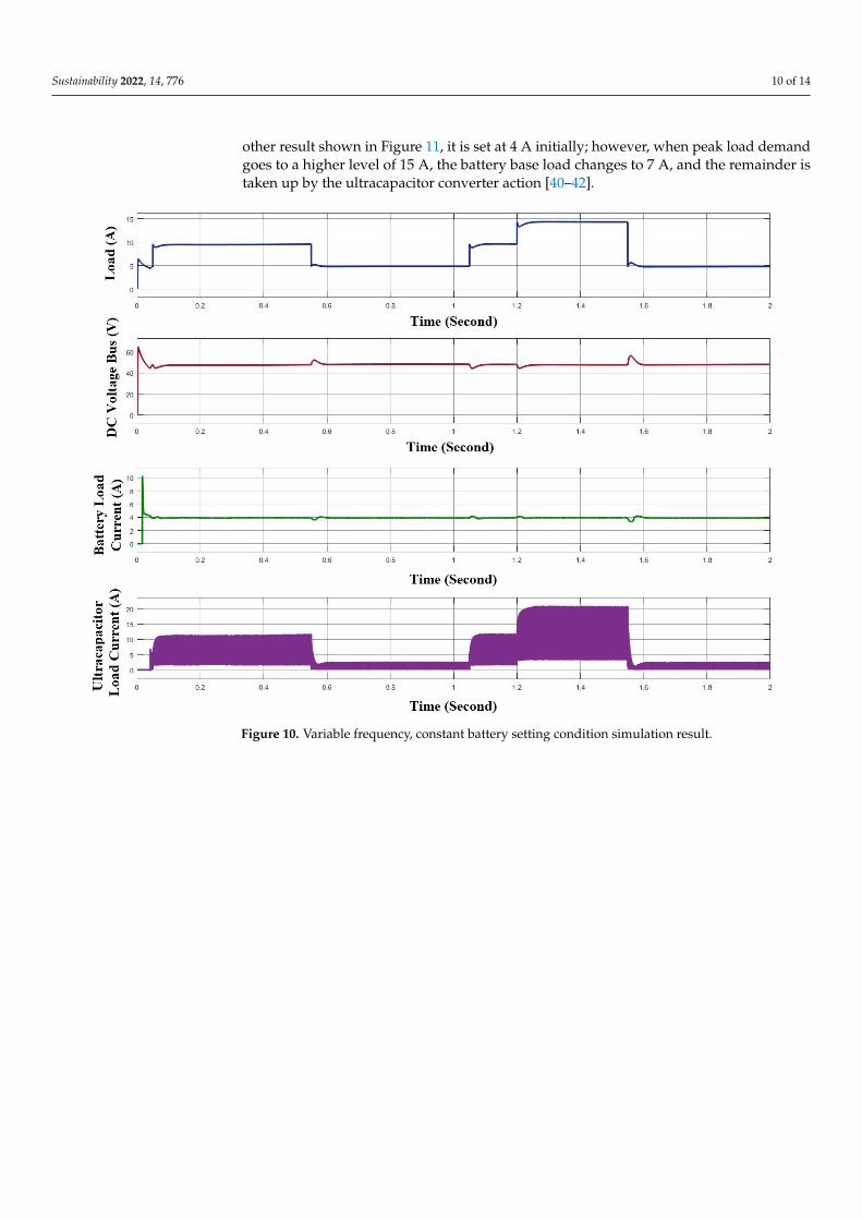
As shown in Figure 10, this mode incorporates the sample drive cycle, which hasthree levels of load changes with variable frequency. Two different results are shown inFigures 10 and 11, one for higher SOC level batteries and another for lower SOC levelbatteries, respectively. When the battery is fully charged or has a sufficient amount ofSOC, the battery converter’s base amount of average load is changed to save ultracapacitorpower and improve overall EV performance, as shown in Figure 11. In the first result,Figure 10, the battery reference base load is set constant at 4 A (low SOC situation). In the
Sustainability 2022, 14, 776 10 of 14
other result shown in Figure 11, it is set at 4 A initially; however, when peak load demandgoes to a higher level of 15 A, the battery base load changes to 7 A, and the remainder istaken up by the ultracapacitor converter action [40–42].
Sustainability 2021, 13, x FOR PEER REVIEW 10 of 14
5.2. Mode 2 As shown in Figure 10, this mode incorporates the sample drive cycle, which has
three levels of load changes with variable frequency. Two different results are shown in Figure 11 and Figure 10, one for higher SOC level batteries and another for lower SOC level batteries, respectively. When the battery is fully charged or has a sufficient amount of SOC, the battery converter’s base amount of average load is changed to save ultraca-pacitor power and improve overall EV performance, as shown in Figure 11. In the first result, Figure10, the battery reference base load is set constant at 4 A (low SOC situation). In the other result shown in Figure 11, it is set at 4 A initially; however, when peak load demand goes to a higher level of 15 A, the battery base load changes to 7 A, and the re-mainder is taken up by the ultracapacitor converter action [40–42].
Figure 10. Variable frequency, constant battery setting condition simulation result. Figure 10. Variable frequency, constant battery setting condition simulation result.

Sustainability 2022, 14, 776 11 of 14Sustainability 2021, 13, x FOR PEER REVIEW 11 of 14
Figure 11. Variable frequency, variable battery setting condition simulation result.
Figure 12 represents the model flowchart approach of this HESS rule-based scheme. The rules are based on certain values of SOC% of a battery and an ultracapacitor. Here, the limit SOC% values are 50% and 70% for ultracapacitor and battery, respectively.
Figure 12. Model flowchart of the rule-based HESS system.
Figure 11. Variable frequency, variable battery setting condition simulation result.
Figure 12 represents the model flowchart approach of this HESS rule-based scheme.The rules are based on certain values of SOC% of a battery and an ultracapacitor. Here,the limit SOC% values are 50% and 70% for ultracapacitor and battery, respectively.
Sustainability 2021, 13, x FOR PEER REVIEW 11 of 14
Figure 11. Variable frequency, variable battery setting condition simulation result.
Figure 12 represents the model flowchart approach of this HESS rule-based scheme. The rules are based on certain values of SOC% of a battery and an ultracapacitor. Here, the limit SOC% values are 50% and 70% for ultracapacitor and battery, respectively.
Figure 12. Model flowchart of the rule-based HESS system. Figure 12. Model flowchart of the rule-based HESS system.

Sustainability 2022, 14, 776 12 of 14
The SOC level of an ultracapacitor is generally taken as 50% due to its efficiency beingdrastically reduced below this level of SOC. In the case of a battery, SOC rules can bechanged according to application and user needs.
5.3. Mode 3
The EV active HESS scheme with multiple levels, as shown in Figure 5, is implementedwith a WLTC Class 1 load profile obtained from the vehicle dynamic model, as shown inFigure 3. Figure 12 depicts the drive load applied to an EV system and load splitting be-tween the hybrid sources. The comparative result in Figure 13 represents the instantaneousbase load change of the battery with the high-power switching action of the ultracapacitorconverter action to meet the standard scaled-down EV WLTC Class 1 load demand [7,16].The battery converter governed by the CCM mode effectively changes its reference loadsetting with a HESS selector logic action. This setting is selected by the different SOCconditions of the hybrid source for effective and efficient utilization of the combined sourcethroughout a test drive cycle.
Sustainability 2021, 13, x FOR PEER REVIEW 12 of 14
The SOC level of an ultracapacitor is generally taken as 50% due to its efficiency be-ing drastically reduced below this level of SOC. In the case of a battery, SOC rules can be changed according to application and user needs.
5.3. Mode 3 The EV active HESS scheme with multiple levels, as shown in Figure 5, is imple-
mented with a WLTC Class 1 load profile obtained from the vehicle dynamic model, as shown in Figure 3. Figure 12 depicts the drive load applied to an EV system and load splitting between the hybrid sources. The comparative result in Figure 13 represents the instantaneous base load change of the battery with the high-power switching action of the ultracapacitor converter action to meet the standard scaled-down EV WLTC Class 1 load demand [7,16]. The battery converter governed by the CCM mode effectively changes its reference load setting with a HESS selector logic action. This setting is selected by the different SOC conditions of the hybrid source for effective and efficient utilization of the combined source throughout a test drive cycle.
Figure 13. WLTC Class 1 load profile HESS load distribution simulation result.
6. Conclusions This paper proposes and investigates a different approach to a rule-based active
power HESS for a low-power Class 1 EV. The hybrid source implementation methodology is applied with proper testing under the standard EV load profile. The standard WLTC Class 1 drive input dynamic model is developed in a MATLAB/Simulink environment to obtain the required effective test instantaneous pulse load profile. Various test conditions are simulated to test EV HESS maintenance of specified voltage regulations and peak power management under the designed EV pulse load profile in the MATLAB/Simulink environment. Furthermore, the DC-DC converter with different controlling schemes for the battery CMC and ultracapacitor controller (SMC) is interfaced with the DC link, which is analyzed at different load conditions. The proposed HESS active power scheme offers efficient and superior control during the drive run of an EV by reducing the stress on the battery. Hence, the controllability of the system is enhanced. Various mode simulation results effectively demonstrate the active power splitting between the battery and ultra-capacitor hybrid source on the basis of energy storage device SOC, peak load requirement, instantaneous fluctuations in an EV load, and load voltage regulations. In future work, an
Figure 13. WLTC Class 1 load profile HESS load distribution simulation result.
6. Conclusions
This paper proposes and investigates a different approach to a rule-based activepower HESS for a low-power Class 1 EV. The hybrid source implementation methodologyis applied with proper testing under the standard EV load profile. The standard WLTCClass 1 drive input dynamic model is developed in a MATLAB/Simulink environment toobtain the required effective test instantaneous pulse load profile. Various test conditionsare simulated to test EV HESS maintenance of specified voltage regulations and peakpower management under the designed EV pulse load profile in the MATLAB/Simulinkenvironment. Furthermore, the DC-DC converter with different controlling schemes forthe battery CMC and ultracapacitor controller (SMC) is interfaced with the DC link, whichis analyzed at different load conditions. The proposed HESS active power scheme offersefficient and superior control during the drive run of an EV by reducing the stress on thebattery. Hence, the controllability of the system is enhanced. Various mode simulationresults effectively demonstrate the active power splitting between the battery and ultraca-pacitor hybrid source on the basis of energy storage device SOC, peak load requirement,instantaneous fluctuations in an EV load, and load voltage regulations. In future work,an EV load profile during the deceleration period can be used to study the regenerationperiod of ultracapacitors in order to extend the EV range of covers.

Sustainability 2022, 14, 776 13 of 14
Author Contributions: Conceptualization, A.K., A.R.G., O.P.M., B.K., M.B.S. and M.G.H.; methodol-ogy, A.K., A.R.G., O.P.M., B.K., M.B.S. and M.G.H.; software, A.K., A.R.G., O.P.M., B.K., M.B.S. andM.G.H.; validation, A.K., A.R.G., O.P.M., B.K., M.B.S. and M.G.H.; formal analysis, A.K., A.R.G.,O.P.M., B.K., M.B.S. and M.G.H.; investigation, A.K., A.R.G., O.P.M., B.K., M.B.S. and M.G.H.; re-sources, A.K., A.R.G., O.P.M., B.K., M.B.S. and M.G.H.; data curation, A.K., A.R.G., O.P.M., B.K.,M.B.S. and M.G.H.; writing—original draft preparation, A.K., A.R.G., O.P.M., B.K., M.B.S. andM.G.H.; writing—review and editing, A.K., A.R.G., O.P.M., B.K., M.B.S. and M.G.H.; visualization,A.K., A.R.G., O.P.M., B.K., M.B.S. and M.G.H.; supervision, O.P.M. and B.K.; project administration,A.K., A.R.G., O.P.M., B.K., M.B.S. and M.G.H.; funding acquisition, M.G.H. and G.I.R. All authorshave read and agreed to the published version of the manuscript.
Funding: This research received no external funding.
Institutional Review Board Statement: Not applicable.
Informed Consent Statement: Not applicable.
Data Availability Statement: No new data were created or analyzed in this study. Data sharing isnot applicable to this article.
Conflicts of Interest: The authors declare no conflict of interest.
References1. Fiori, C.; Ahn, K.; Rakha, H.A. Power-based electric vehicle energy consumption model: Model development and validation.
Appl. Energy 2016, 168, 257–268. [CrossRef]2. Kuperman, A.; Aharon, I. Battery–ultracapacitor hybrids for pulsed current loads: A review. Renew. Sustain. Energy Rev. 2011, 15,
981–992. [CrossRef]3. Nikolaidis, P.; Poullikkas, A. A comparative review of electrical energy storage systems for better sustainability. J. Power Technol.
2017, 97, 220–245.4. Zimmermann, T.; Keil, P.; Hofmann, M.; Horsche, M.F.; Pichlmaier, S.; Jossen, A. Review of system topologies for hybrid electrical
energy storage systems. J. Energy Storage 2016, 8, 78–90. [CrossRef]5. Mishra, R.; Saxena, R. Comprehensive review of control schemes for battery and super-capacitor energy storage system. In
Proceedings of the 7th International Conference on Power Systems (ICPS), Pune, India, 21–23 December 2017; pp. 702–707.6. Deshpande, G.; Kamalasadan, S. An approach for micro grid management with hybrid energy storage system using batteries and
ultra capacitors. In Proceedings of the 2014 IEEE PES General Meeting Conference & Exposition, National, Harbor, MD, USA,27–31 July 2014.
7. Kachhwaha, A.; Shah, V.A.; Shimin, V.V. Integration methodology of ultracapacitor-battery based hybrid energy storage systemfor electrical vehicle power management. In Proceedings of the 2016 IEEE 7th Power India International Conference (PIICON),Bikaner, India, 25–27 November 2016; pp. 1–6. [CrossRef]
8. Li, J.; Gee, A.M.; Zhang, M.; Yuan, W. Analysis of battery lifetime extension in a SMES-battery hybrid energy storage systemusing a novel battery lifetime model. Energy 2015, 86, 175–185. [CrossRef]
9. Allegre, A.L.; Bouscayrol, A.; Trigui, R. Influence of control strategies on battery/supercapacitor hybrid Energy Storage Systemsfor traction applications. In Proceedings of the IEEE Vehicle Power and Propulsion Conference, Dearborn, MI, USA, 7–10September 2009.
10. Carter, R.; Cruden, A.; Hall, P.J. Optimizing for Efficiency or Battery Life in a Battery/Supercapacitor Electric Vehicle. IEEE Trans.Veh. Technol. 2012, 61, 1526–1533. [CrossRef]
11. Song, Z.; Hofmann, H.; Li, J.; Hou, J.; Han, X.; Ouyang, M. Energy management strategies comparison for electric vehicles withhybrid energy storage system. Appl. Energy 2014, 134, 321–331. [CrossRef]
12. Hadartz, M.; Julander, M. Battery-Supercapacitor Energy Storage; University of Chalmers: Goteborg, Sweden, 2008.13. Hung, Y.-H.; Wu, C.-H. An integrated optimization approach for a hybrid energy system in electric vehicles. Appl. Energy 2012,
98, 479–490. [CrossRef]14. Song, Z.; Hofmann, H.; Li, J.; Han, X.; Ouyang, M. Optimization for a hybrid energy storage system in electric vehicles using
dynamic programing approach. Appl. Energy 2015, 139, 151–162. [CrossRef]15. Khalid, M. A Review on the Selected Applications of Battery-Supercapacitor Hybrid Energy Storage Systems for Microgrids.
Energies 2019, 12, 4559. [CrossRef]16. Roche, M.; Sabrià, D.; Mammetti, M. An Accessible Predesign Calculation Tool to Support the Definition of EV Components.
World Electr. Veh. J. 2015, 7, 101–113. [CrossRef]17. Xu, W.; Hussien, M.G.; Liu, Y.; Allam, S.M. Sensorless Control of Ship Shaft Stand-Alone BDFIGs Based on Reactive-Power MRAS
Observer. IEEE J. Emerg. Sel. Top. Power Electron. 2019, 9, 1518–1531. [CrossRef]18. Xu, W.; Hussien, M.G.; Liu, Y.; Islam, R.; Allam, S.M. Sensorless Voltage Control Schemes for Brushless Doubly-Fed Induction
Generators in Stand-Alone and Grid-Connected Applications. IEEE Trans. Energy Convers. 2020, 35, 1781–1795. [CrossRef]

Sustainability 2022, 14, 776 14 of 14
19. Hussien, M.G. A new robust sensorless vector-control strategy for wound-rotor induction motors. Aust. J. Electr. Electron. Eng.2020, 17, 132–137. [CrossRef]
20. Hussien, M.G.; Liu, Y.; Xu, W. Robust position observer for sensorless direct voltage control of stand-alone ship shaft brushlessdoubly-fed induction generators. China Electro. Soc. Trans. Electr. Mach. Syst. 2019, 3, 363–376. [CrossRef]
21. Hussien, M.G.; Xu, W.; Liu, Y.; Allam, S.M. Rotor Speed Observer with Extended Current Estimator for Sensorless Control ofInduction Motor Drive Systems. Energies 2019, 12, 3613. [CrossRef]
22. Hussien, M.G.; Liu, Y.; Xu, W.; Junejo, A.K.; Allam, S. Improved MRAS Rotor Position Observer Based on Control Winding PowerFactor for Stand-Alone Brushless Doubly-Fed Induction Generators. IEEE Trans. Energy Convers. 2021, 1. [CrossRef]
23. Hussien, M.G.; Hassan, A.E.-W. Mathematical Analysis of the Small Signal Model for Voltage-Source Inverter in SPMSM DriveSystems. In Proceedings of the 2019 21st International Middle East Power Systems Conference (MEPCON), Cairo, Egypt, 17–19December 2019; pp. 540–549.
24. Liu, Y.; Hussien, M.G.; Xu, W.; Shao, S.; Rashad, E.M. Recent Advances of Control Technologies for Brushless Doubly-FedGenerators. IEEE Access 2021, 9, 123324–123347. [CrossRef]
25. Karmaker, A.K.; Hossain, M.A.; Manoj Kumar, N.; Jagadeesan, V.; Jayakumar, A.; Ray, B. Analysis of Using Biogas Resources forElectric Vehicle Charging in Bangladesh: A Techno-Economic-Environmental Perspective. Sustainability 2020, 12, 2579. [CrossRef]
26. Podder, A.K.; Chakraborty, O.; Islam, S.; Kumar, N.M.; Alhelou, H.H. Control Strategies of Different Hybrid Energy StorageSystems for Electric Vehicles Applications. IEEE Access 2021, 9, 51865–51895. [CrossRef]
27. Odeim, F.; Roes, J.; Heinzel, A. Power Management Optimization of an Experimental Fuel Cell/Battery/Supercapacitor HybridSystem. Energies 2015, 8, 6302–6327. [CrossRef]
28. Lahyani, A.; Venet, P.; Guermazi, A.; Troudi, A. Battery/Supercapacitors Combination in Uninterruptible Power Supply (UPS).IEEE Trans. Power Electron. 2012, 28, 1509–1522. [CrossRef]
29. Schupbach, R.M.; Balda, J.C. Comparing DC-DC converters for Power Management in Hybrid Electric. In Proceedings of theElectrical Machines and Drives Conference, Madison, WI, USA, 1–4 June 2003; Volume 3, pp. 1369–1374.
30. Utkin, V. Sliding mode control of DC/DC converters. J. Frankl. Inst. 2013, 350, 2146–2165. [CrossRef]31. Shina, D.; Kima, Y.; Wangb, Y.; Changa, N.; Pedramb, M. Constant-current regulator-based battery supercapacitor hybrid
architecture for high-rate pulsed load applications. J. Power Sources 2012, 205, 516–524. [CrossRef]32. Lukic, S.M.; Wirasingha, S.G.; Rodriguez, F.; Cao, J.; Emadi, A. Power management of an ultracapacitor/battery hybrid energy
storage system in an hev. In Proceedings of the IEEE Vehicle Power and Propulsion Conference, Windsor, UK, 6–8 September2006. pp. 1–6.
33. Etxeberria, A.; Vechiu, I.; Camblong, H.; Vinassa, J.-M. Comparison of Sliding Mode and PI Control of a Hybrid Energy StorageSystem in a Microgrid Application. Energy Procedia 2011, 12, 966–974. [CrossRef]
34. Khaligh, A.; Li, Z. Battery, Ultracapacitor, Fuel Cell, and Hybrid Energy Storage Systems for Electric, Hybrid Electric, Fuel Cell,and Plug-In Hybrid Electric Vehicles: State of the Art. IEEE Trans. Veh. Technol. 2010, 59, 2806–2814. [CrossRef]
35. Vadlamudi, S.D.V.R.; Kumtepeli, V.; Ozcira, S.; Tripathi, A. Hybrid energy storage power allocation and motor control for electricforklifts. In Proceedings of the 2016 Asian Conference Energy, Power and Transportation Electrification (ACEPT) 2016, Singapore,25–27 October 2016; pp. 1–5.
36. Meyer, R.T.; Decarlo, R.A.; Pekarek, S. Hybrid model predictive power management of a battery-supercapacitor electric vehicle.Asian J. Control 2016, 18, 150–165. [CrossRef]
37. Sahin, M.E.; Blaabjerg, F. A Hybrid PV-Battery/Supercapacitor System and a Basic Active Power Control Proposal in MAT-LAB/Simulink. Electronics 2020, 9, 129. [CrossRef]
38. Shen, J.; Khaligh, A. A Supervisory Energy Management Control Strategy in a Battery/Ultracapacitor Hybrid Energy StorageSystem. IEEE Trans. Transp. Electrif. 2015, 1, 223–231. [CrossRef]
39. Malkawi, A.M.A.; Lopes, L.A.C. Improved Dynamic Voltage Regulation in a Droop Controlled DC Nanogrid EmployingIndependently Controlled Battery and Supercapacitor Units. Appl. Sci. 2018, 8, 1525. [CrossRef]
40. Wang, X.; Yu, D.; Le Blond, S.; Zhao, Z.; Wilson, P. A novel controller of a battery-supercapacitor hybrid energy storage sys-temfor domestic applications. Energy Build. 2017, 141, 167–174. [CrossRef]
41. Laldin, O.; Moshirvaziri, M.; Trescases, O. Predictive algorithm for optimizing power flow in hybrid ultracapacitor/batterystorage systems for light electric vehicles. IEEE Trans. Power Electron. 2012, 28, 3882–3895. [CrossRef]
42. Trovão, J.P.; Santos, V.; Antunes, C.H.; Pereirinha, P.; Jorge, H. A Real-Time Energy Management Architecture for MultisourceElectric Vehicles. IEEE Trans. Ind. Electron. 2014, 62, 3223–3233. [CrossRef]